Safety relief valves, type SFV 20 - 25 -...
12
Safety relief valves, type SFV 20 - 25 Technical leaflet REFRIGERATION AND AIR CONDITIONING
Transcript of Safety relief valves, type SFV 20 - 25 -...
Safety relief valves,type SFV 20 - 25
Technical leafletREFRIGERATION AND AIR CONDITIONING
2 DKRCI.PD.IB0.A3.02 / 520H0710 Danfoss A/S (AC-AKS / frz), 08 - 2008
Technical leaflet Safety relief valves, type SFV 20 - 25
Contents Page
Introduction. . . . . . . . . . . . . . . . . . . . . . . . . . . . . . . . . . . . . . . . . . . . . . . . . . . . . . . . . . . . . . . . . . . . . . . . . . . . . . . . . . . . . . . .3
Features . . . . . . . . . . . . . . . . . . . . . . . . . . . . . . . . . . . . . . . . . . . . . . . . . . . . . . . . . . . . . . . . . . . . . . . . . . . . . . . . . . . . . . . . . . . .3
Technical data . . . . . . . . . . . . . . . . . . . . . . . . . . . . . . . . . . . . . . . . . . . . . . . . . . . . . . . . . . . . . . . . . . . . . . . . . . . . . . . . . . . . . .4
Design . . . . . . . . . . . . . . . . . . . . . . . . . . . . . . . . . . . . . . . . . . . . . . . . . . . . . . . . . . . . . . . . . . . . . . . . . . . . . . . . . . . . . . . . . . . . .5
Capacity. . . . . . . . . . . . . . . . . . . . . . . . . . . . . . . . . . . . . . . . . . . . . . . . . . . . . . . . . . . . . . . . . . . . . . . . . . . . . . . . . . . . . . . . . . . .6
Material specification . . . . . . . . . . . . . . . . . . . . . . . . . . . . . . . . . . . . . . . . . . . . . . . . . . . . . . . . . . . . . . . . . . . . . . . . . . . . . . .9
Connections. . . . . . . . . . . . . . . . . . . . . . . . . . . . . . . . . . . . . . . . . . . . . . . . . . . . . . . . . . . . . . . . . . . . . . . . . . . . . . . . . . . . . . 10
Dimensions and weights . . . . . . . . . . . . . . . . . . . . . . . . . . . . . . . . . . . . . . . . . . . . . . . . . . . . . . . . . . . . . . . . . . . . . . . . . . 10
Ordering . . . . . . . . . . . . . . . . . . . . . . . . . . . . . . . . . . . . . . . . . . . . . . . . . . . . . . . . . . . . . . . . . . . . . . . . . . . . . . . . . . . . . . . . . 11
Danfoss A/S (AC-AKC / frz), 08 - 2008 DKRCI.PD.IB0.A3.02 / 520H0710 3
Technical leaflet Safety relief valves, type SFV 20 - 25
Introduction
Features
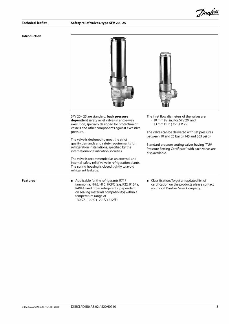
SFV 20 - 25 are standard, back pressure dependent safety relief valves in angle-way execution, specially designed for protection of vessels and other components against excessive pressure.
The valve is designed to meet the strict quality demands and safety requirements for refrigeration installations, specified by the international classification societies.
The valve is recommended as an external and internal safety relief valve in refrigeration plants. The spring housing is closed tightly to avoid refrigerant leakage.
Applicable for the refrigerants R717 (ammonia, NH3), HFC, HCFC (e.g. R22, R134a, R404A) and other refrigerants (dependent on sealing materials compatibility) within a temperature range of –30°C/+100°C (–22°F/+212°F).
The inlet flow diameters of the valves are:18 mm (3/4 in.) for SFV 20, and23 mm (1 in.) for SFV 25.
The valves can be delivered with set pressures between 10 and 25 bar g (145 and 363 psi g).
Standard pressure setting valves having "TÜV Pressure Setting Certificate" with each valve, are also available.
Classification: To get an updated list of certification on the products please contact your local Danfoss Sales Company.
4 DKRCI.PD.IB0.A3.02 / 520H0710 Danfoss A/S (AC-AKS / frz), 08 - 2008
Technical leaflet Safety relief valves, type SFV 20 - 25
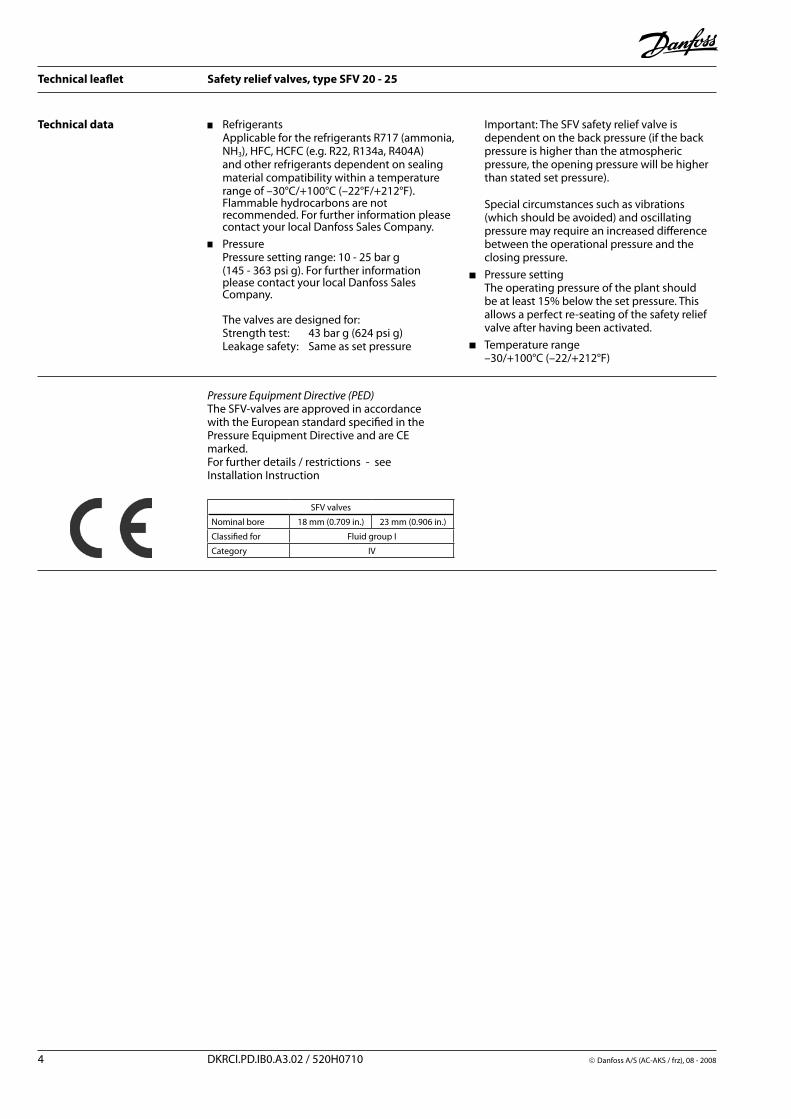
Technical data Refrigerants Applicable for the refrigerants R717 (ammonia, NH3), HFC, HCFC (e.g. R22, R134a, R404A) and other refrigerants dependent on sealing material compatibility within a temperature range of –30°C/+100°C (–22°F/+212°F). Flammable hydrocarbons are not recommended. For further information please contact your local Danfoss Sales Company.
Pressure Pressure setting range: 10 - 25 bar g (145 - 363 psi g). For further information please contact your local Danfoss Sales Company. The valves are designed for: Strength test: 43 bar g (624 psi g) Leakage safety: Same as set pressure
Important: The SFV safety relief valve is dependent on the back pressure (if the back pressure is higher than the atmospheric pressure, the opening pressure will be higher than stated set pressure). Special circumstances such as vibrations (which should be avoided) and oscillating pressure may require an increased difference between the operational pressure and the closing pressure.
Pressure setting The operating pressure of the plant should be at least 15% below the set pressure. This allows a perfect re-seating of the safety relief valve after having been activated.
Temperature range –30/+100°C (–22/+212°F)
Pressure Equipment Directive (PED)The SFV-valves are approved in accordance with the European standard specified in the Pressure Equipment Directive and are CE marked.For further details / restrictions - see Installation Instruction
SFV valves
Nominal bore 18 mm (0.709 in.) 23 mm (0.906 in.)
Classified for Fluid group I
Category IV
Danfoss A/S (AC-AKC / frz), 08 - 2008 DKRCI.PD.IB0.A3.02 / 520H0710 5
Technical leaflet Safety relief valves, type SFV 20 - 25
Design
ConnectionsAvailable with the following connections:
Outside pipe thread T (ISO 228/1)
Welding fittings (DIN 2448)
HousingMade of special steel approved for low temperature operation. Spindle and seat are made of stainless steel, to ensure precise operation even during extraordinary conditions. The gasket of the valve cone is made of a special cloroprene (neoprene) compound.
InstallationTo ensure exact operation of the safety relief valve it should be installed with the spring housing upwards. If the valve is mounted as an internal safety relief valve without any demand for exact opening pressure, the valve may be fitted with the spring housing in other positions. When the valve is mounted, it is important to avoid the influence of static, dynamic and thermal stress.
A very precise technique has been applied for the production of the seal. However, this seal can still be damaged, if dirt is blown from the pipe system into the valve.
It is recommended that safety relief valves exhaust into the open air with a U-pipe filled with oil on the discharge branch, to prevent dirt from penetrating into the valve. It is also recommended that the valves be installed in pairs in conjunction with the double stop valve type DSV. For further information please see the DSV data sheet.
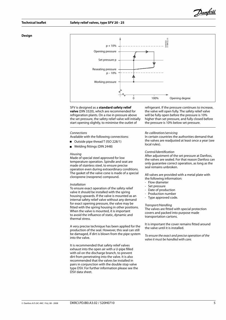
SFV is designed as a standard safety relief valve (DIN 3320), which are recommended for refrigeration plants. On a rise in pressure above the set pressure, the safety relief valve will initially start opening slightly, to minimise the outlet of
Re-calibration/servicingIn certain countries the authorities demand that the valves are readjusted at least once a year (see local rules).
Control/IdentificationAfter adjustment of the set pressure at Danfoss, the valves are sealed. For that reason Danfoss can only guarantee correct operation, as long as the seal remains unbroken.
All valves are provided with a metal plate with the following information: - Flow diameter- Set pressure- Date of production- Production number- Type approved code.
Transport/HandlingThe valves are fitted with special protection covers and packed into purpose made transportation cartons.
It is important the cover remains fitted around the valve until it is installed.
To ensure the exact and precise operation of the valve it must be handled with care.
refrigerant. If the pressure continues to increase, the valve will open fully. The safety relief valve will be fully open before the pressure is 10% higher than set pressure, and fully closed before the pressure is 10% below set pressure.
Working pressure
Reseating pressure
Set pressure p
Opening pressure
p + 10%
p – 10%
0 100% Opening degree
6 DKRCI.PD.IB0.A3.02 / 520H0710 Danfoss A/S (AC-AKS / frz), 08 - 2008
Technical leaflet Safety relief valves, type SFV 20 - 25
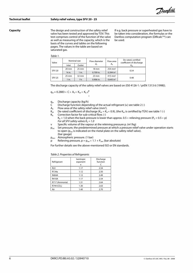
Capacity The design and construction of the safety relief valve has been tested and approved by TÜV. This test comprises control of the function of the valve as well as measuring of the capacity, which is the basis of the curves and tables on the following pages. The values in the table are based on saturated gas.
If e.g. back pressure or superheated gas have to be taken into consideration, the formulas or the Danfoss computation program (DIRcalc) can be used.
qm Discharge capacity (kg/h)C Discharge function depending of the actual refrigerant (κ) see table 2 (-)A0 Flow area of the safety relief valve (mm2).Kdr De-rated coefficient of discharge (Kdr = Kd × 0.9), (the Kdr is certified by TÜV) see table 1 (-)Kb Correction factor for sub-critical flow. (-) Kb = 1.0 when the back pressure is lower than approx. 0.5 × relieving pressure (Pb < 0.5 × p) For all SFV safety valves Kb = 1.0v Specific volume of the vapour at the releiving pressure p. (m3/kg)pset Set pressure, the predetermined pressure at which a pressure relief valve under operation starts to open (pset is indicated on the metal plate on the safety relief valve). (bar gauge)patm Atmospheric pressure. (1 bar)p Relieving pressure, p = pset × 1.1 + Patm (bar absolute)
For further details see the above-mentioned ISO or EN standards.
Table 1.
Table 2. Properties of Refrigerants
RefrigerantIsentropic exponent
κ
Dischargefunction
C
R22 1.17 2.54
R134a 1.12 2.50
R404A 1.12 2.49
R410A 1.17 2.54
R717 (Ammonia) 1.31 2.64
R744 (CO2) 1.30 2.63
Air 1.40 2.70
ValveNominal size Flow diameter
do
Flow areaA0
De-rated, certified coefficient of discharge
KdrInlet Outlet
SFV 2020 mm 25 mm 18 mm 254 mm2
0.54¾ in. 1 in. 0.709 in. 0.394 in2
SFV 2525 mm 32 mm 23 mm 415 mm2
0.481 in. 1¼ 0.906 in. 0.643 in2
The discharge capacity of the safety relief valves are based on (IS0 4126-1 / prEN 1313 6 (1998)).
qm = 0.2883 × C × A0 × Kdr × Kb √p
v

Danfoss A/S (AC-AKC / frz), 08 - 2008 DKRCI.PD.IB0.A3.02 / 520H0710 7
Technical leaflet Safety relief valves, type SFV 20 - 25
SFV 20
Set pressure R22 R134a R404A R717 Air (20°C)
SFV 20
13 bar g189 psi g
kg/hlb/min
3220118
3430126
3500129
141552
179066
18 bar g261 psi g
kg/hlb/min
4440163
4800176
4900180
192571
243589
21 bar g305 psi g
kg/hlb/min
5215192
5680209
5770212
223582
2820104
25 bar g363 psi g
kg/hlb/min
6285231
6980257
7125262
266098
3335122
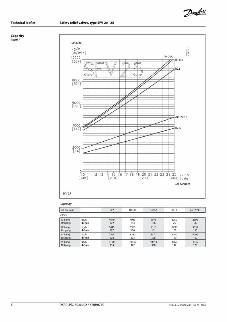
Capacity
Set pressure
Capacity
R717
R404AR134a
Air (20°C)
R22
Capacity(cont.)
8 DKRCI.PD.IB0.A3.02 / 520H0710 Danfoss A/S (AC-AKS / frz), 08 - 2008
Technical leaflet Safety relief valves, type SFV 20 - 25
Set pressure R22 R134a R404A R717 Air (20°C)
SFV 25
13 bar g189 psi g
kg/hlb/min
4670172
4980183
5075186
205075
260096
18 bar g261 psi g
kg/hlb/min
6445237
6965256
7115261
2790103
3530130
21 bar g305 psi g
kg/hlb/min
7565278
8240303
8370308
3240119
4090150
25 bar g363 psi g
kg/hlb/min
9120335
10135372
10340380
3860142
4835178
Capacity
SFV 25
Set pressure
Capacity
R717
R404AR134a
Air (20°C)
R22
Capacity(cont.)

Danfoss A/S (AC-AKC / frz), 08 - 2008 DKRCI.PD.IB0.A3.02 / 520H0710 9
Technical leaflet Safety relief valves, type SFV 20 - 25
Material specification
No. Part Material DIN ISO ASTM
1 Housing Steel TT St 35 N, 17173 TW 6, 2604/3-75 Grade 1, A333, A334* A350 LF2
2 Valve seat Stainless steel X10CrNiS189, 17440 Type 17, 683/13 AISI 303
3 Packing washer Aluminium*Non-asbestos gasket
4 Valve top Steel St. 37.2, 1652 Fe 360 B, 660 Grade C, A 283
6 Valve spindle Stainless steel X10CrNiS189, 17440 Type 17, 683/13 AISI 303
10 Valve cone Steel
11 Valve cone seal Cloroprene (Neoprene)
15 Packing washer Aluminium*Non-asbestos gasket
17 Spring Steel Class C A 679, 17223
23 Packing washer Aluminum*Non-asbestos gasket
24 Plug Steel 9S Mn28, 1651*R St 37.2, 17100
Type 2, R 683Fe 360 B, 630 Grade C, A 283
25 Marking label Aluminium
* Alternative material

10 DKRCI.PD.IB0.A3.02 / 520H0710 Danfoss A/S (AC-AKS / frz), 08 - 2008
Technical leaflet Safety relief valves, type SFV 20 - 25
Connections
T
DIN Size Size Inlet (mm) Inlet (in.) Outlet (mm) Outlet (in.)
mm in. OD T OD T OD T OD T
Welding fittings DIN (2448)2025
3/4
126.933.7
2.32.6
1.0591.327
0.0910.102
33.742.4
2.62.6
1.3371.669
0.1020.102
Dimensions and weightsSFV 20 - 25 T SFV 20 - 25 with
welding fittings (flanges)
Sizemm
Sizein.
Inlet OutletL
mmL
in.
T outside pipe thread, (ISO 228/1)2025
¾1
G 1¼G 1¼
G 1½G 1½
2020
0.790.79
Valve size A B C D0 øD D1 AF Weight
SFV 20 - 25 T, with threaded connections ISO 228/1 pipe threads
SFV 20 (3/4 in.)mmin.
552.17
27010.63
401.57
602.36
602.36 4.2 kg
SFV 25 (1 in.)mmin.
552.17
27010.63
401.57
602.36
602.36 4.2 kg
SFV with welding fittings, DIN 2448
SFV 20 (3/4 in.)mmin.
853.35
30011.81
903.54
602.36
903.54
602.36 6.0 kg
SFV 25 (1 in.)mmin.
853.35
30011.81
903.54
602.36
903.54
602.36 6.0 kg
Specified weights are approximate values only.
Danfoss A/S (AC-AKC / frz), 08 - 2008 DKRCI.PD.IB0.A3.02 / 520H0710 11
Technical leaflet Safety relief valves, type SFV 20 - 25
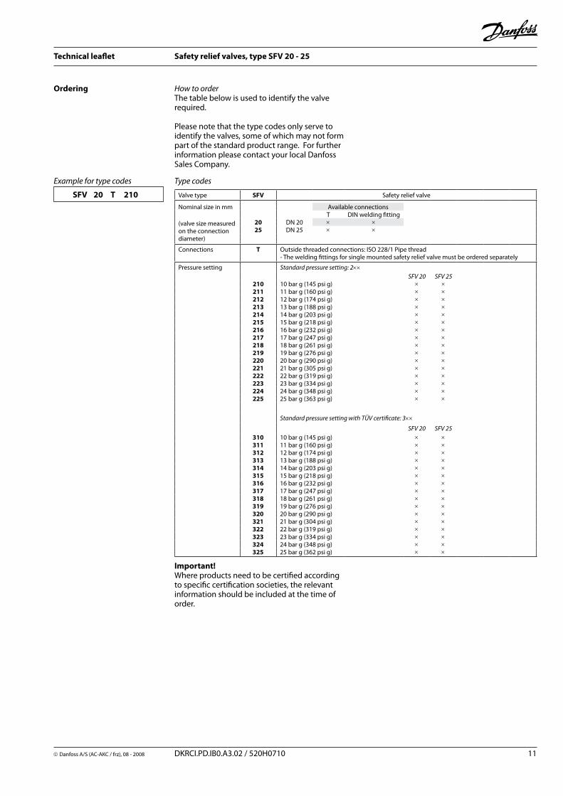
Ordering How to orderThe table below is used to identify the valve required.
Please note that the type codes only serve to identify the valves, some of which may not form part of the standard product range. For further information please contact your local Danfoss Sales Company.
Type codesExample for type codes
SFV 20 T 210
Important!Where products need to be certified according to specific certification societies, the relevant information should be included at the time of order.
Valve type SFV Safety relief valve
Nominal size in mm
(valve size measured on the connection diameter)
Available connectionsT DIN welding fitting
20 DN 20 × ×25 DN 25 × ×
Connections T Outside threaded connections: ISO 228/1 Pipe thread- The welding fittings for single mounted safety relief valve must be ordered separately
Pressure setting Standard pressure setting: 2××SFV 20 SFV 25
210 10 bar g (145 psi g) × ×211 11 bar g (160 psi g) × ×212 12 bar g (174 psi g) × ×213 13 bar g (188 psi g) × ×214 14 bar g (203 psi g) × ×215 15 bar g (218 psi g) × ×216 16 bar g (232 psi g) × ×217 17 bar g (247 psi g) × ×218 18 bar g (261 psi g) × ×219 19 bar g (276 psi g) × ×220 20 bar g (290 psi g) × ×221 21 bar g (305 psi g) × ×222 22 bar g (319 psi g) × ×223 23 bar g (334 psi g) × ×224 24 bar g (348 psi g) × ×225 25 bar g (363 psi g) × ×
Standard pressure setting with TÜV certificate: 3××
SFV 20 SFV 25310 10 bar g (145 psi g) × ×311 11 bar g (160 psi g) × ×312 12 bar g (174 psi g) × ×313 13 bar g (188 psi g) × ×314 14 bar g (203 psi g) × ×315 15 bar g (218 psi g) × ×316 16 bar g (232 psi g) × ×317 17 bar g (247 psi g) × ×318 18 bar g (261 psi g) × ×319 19 bar g (276 psi g) × ×320 20 bar g (290 psi g) × ×321 21 bar g (304 psi g) × ×322 22 bar g (319 psi g) × ×323 23 bar g (334 psi g) × ×324 24 bar g (348 psi g) × ×325 25 bar g (362 psi g) × ×

12 DKRCI.PD.IB0.A3.02 / 520H0710 Danfoss A/S (AC-AKS / frz), 08 - 2008
Technical leaflet Safety relief valves, type SFV 20 - 25
Certified SFV valves with standard set pressure Certified SFV valves with standard set pressure and TÜV pressure setting certificate with each valve
Size Construction and test facilities are approved by TÜV
mm in. Type Bar g (psi g) Part no.
20 3/4 SFV20 T 210 10 (145) 2416+254
20 3/4 SFV20 T 211 11 (160) 2416+255
20 3/4 SFV20 T 212 12 (174) 2416+256
20 3/4 SFV20 T 213 13 (189) 2416+150
20 3/4 SFV20 T 214 14 (203) 2416+257
20 3/4 SFV20 T 215 15 (218) 2416+258
20 3/4 SFV20 T 216 16 (232) 2416+259
20 3/4 SFV20 T 217 17 (247) 2416+260
20 3/4 SFV20 T 218 18 (261) 2416+151
20 3/4 SFV20 T 219 19 (276) 2416+261
20 3/4 SFV20 T 220 20 (290) 2416+262
20 3/4 SFV20 T 221 21 (305) 2416+152
20 3/4 SFV20 T 222 22 (319) 2416+241
20 3/4 SFV20 T 223 23 (334) 2416+263
20 3/4 SFV20 T 224 24 (348) 2416+264
20 3/4 SFV20 T 225 25 (363) 2416+183
Size Each valve is certified by a representative from TÜV
mm in. Type Bar g (psi g) Part no.
20 3/4 SFV20 T 310 10 (145) 2416+285
20 3/4 SFV20 T 311 11 (160) 2416+286
20 3/4 SFV20 T 312 12 (174) 2416+287
20 3/4 SFV20 T 313 13 (189) 2416+160
20 3/4 SFV20 T 314 14 (203) 2416+288
20 3/4 SFV20 T 315 15 (218) 2416+289
20 3/4 SFV20 T 316 16 (232) 2416+290
20 3/4 SFV20 T 317 17 (247) 2416+291
20 3/4 SFV20 T 318 18 (261) 2416+161
20 3/4 SFV20 T 319 19 (276) 2416+292
20 3/4 SFV20 T 320 20 (290) 2416+293
20 3/4 SFV20 T 321 21 (305) 2416+162
20 3/4 SFV20 T 322 22 (319) 2416+294
20 3/4 SFV20 T 323 23 (334) 2416+295
20 3/4 SFV20 T 324 24 (348) 2416+296
20 3/4 SFV20 T 325 25 (363) 2416+186
Ordering(cont.)
Certified SFV valves with standard set pressure Certified SFV valves with standard set pressure and TÜV pressure setting certificate with each valve
Size Construction and test facilities are approved by TÜV
mm in. Type Bar g (psi g) Part no.
25 1 SFV25 T 210 10 (145) 2416+265
25 1 SFV25 T 211 11 (160) 2416+266
25 1 SFV25 T 212 12 (174) 2416+267
25 1 SFV25 T 213 13 (189) 2416+153
25 1 SFV25 T 214 14 (203) 2416+268
25 1 SFV25 T 215 15 (218) 2416+269
25 1 SFV25 T 216 16 (232) 2416+270
25 1 SFV25 T 217 17 (247) 2416+271
25 1 SFV25 T 218 18 (261) 2416+154
25 1 SFV25 T 219 19 (276) 2416+272
25 1 SFV25 T 220 20 (290) 2416+273
25 1 SFV25 T 221 21 (305) 2416+155
25 1 SFV25 T 222 22 (319) 2416+242
25 1 SFV25 T 223 23 (334) 2416+274
25 1 SFV25 T 224 24 (348) 2416+275
25 1 SFV25 T 225 25 (363) 2416+184
Size Each valve is certified by a representative from TÜV
mm in. Type Bar g (psi g) Part no.
25 1 SFV25 T 310 10 (145) 2416+297
25 1 SFV25 T 311 11 (160) 2416+298
25 1 SFV25 T 312 12 (174) 2416+299
25 1 SFV25 T 313 13 (189) 2416+163
25 1 SFV25 T 314 14 (203) 2416+300
25 1 SFV25 T 315 15 (218) 2416+301
25 1 SFV25 T 316 16 (232) 2416+302
25 1 SFV25 T 317 17 (247) 2416+303
25 1 SFV25 T 318 18 (261) 2416+164
25 1 SFV25 T 319 19 (276) 2416+304
25 1 SFV25 T 320 20 (290) 2416+305
25 1 SFV25 T 321 21 (305) 2416+165
25 1 SFV25 T 322 22 (319) 2416+306
25 1 SFV25 T 323 23 (334) 2416+307
25 1 SFV25 T 324 24 (348) 2416+308
25 1 SFV25 T 325 25 (363) 2416+187
Flanges and gaskets Type Code No.
Flanges + gaskets set for SFV 20 148F3020
Flanges + gaskets set for SFV 25 148F3021
Repair kit Type Code No.
Repair kit for SFV 20 (gaskets and cone) 2453+082
Repair kit for SFV 25 (gaskets and cone) 2453+083