SAFETY PRECAUTIONS - inverter-plc.comA1SJ71DN91 DEVICENET... · Loose terminal screws can cause...
95
Transcript of SAFETY PRECAUTIONS - inverter-plc.comA1SJ71DN91 DEVICENET... · Loose terminal screws can cause...


•• SAFETY PRECAUTIONS ••(Read these precautions before using.)
When using Mitsubishi equipment, thoroughly read this manual and the associated manuals introduced inthis manual. Also pay careful attention to safety and handle the module properly.
These precautions apply only to Mitsubishi equipment. Refer to the CPU module user's manual for adescription of the PC system safety precautions.
These SAFETY PRECAUTIONS classify the safety precautions into two categories: "DANGER" and"CAUTION".
DANGER Procedures which may lead to a dangerous condition and cause death or seriousinjury if not carried out properly.
CAUTION Procedures which may lead to a dangerous condition and cause superficial tomedium injury, or physical damage only, if not carried out properly.
Depending on circumstances, procedures indicated by CAUTION may also be linked to serious results.
In any case, it is important to follow the directions for usage.
Store this manual in a safe place so that you can take it out and read it whenever necessary.Always forward it to the end user.
[System Design Precautions]
DANGER
• If a communication error occurs in the network of the DeviceNet, the communication error station entersthe state shown below.(1) The master station (AJ71DN91, A1SJ71DN91) holds the data that was input from a slave station
before the occurrence of a communication error.
(2) Whether the output signal of the slave station goes OFF or is retained depends on the slave stationspecifications or the parameter setting at the master station.
Create the interlock circuit on a sequence program which uses the communication state of the slavestations so that the system operation is secured. At the same time, a safety system must be providedoutside the slave station.
CAUTION
• Do not bundle control lines or communication wires together with main circuit or power lines, or lay themclose to these lines.As a guide, separate these lines by a distance of at least 100 mm, otherwise malfunctions may occurdue to noise.

[Cautions on Mounting]
CAUTION
• Use the PC in an environment that conforms to the general specifications in the manual.Using the PC in environments outside the ranges stated in the general specifications will cause electricshock, fire, malfunction, or damage to/deterioration of the product.
• Make sure that the module fixing projection on the base of the module is properly engaged in themodule fixing hole in the base unit before mounting the module.(A(1S)J71DN91 must be screwed to thebase unit with the specified torque.)Failure to mount the module properly will result in malfunction or failure, or in the module falling.
• Do not touch conductive parts or electronic components of the module with your bare hands.This could cause malfunction or failure of the module.
[Cautions on Wiring]
DANGER
• Switch off all phases of the power supply outside the PC before starting installing or wiring work.If all phases are not switched off, there will be a danger of electric shock or damage to the product.
CAUTION
• Connect the FG terminal to a dedicated PC ground connection with class 3 grounding or higher.Failure to do this may result in malfunction.
• Tighten terminal screws to the prescribed torque.Loose terminal screws can cause shorting and malfunctions.
• Make sure that no foreign matter such as chips or wire offcuts gets inside the module.It will cause fire, failure, or malfunction.
• The communication cables and power cables connected to the unit must be enclosed in a duct or fixedwith clamps.Failure to do this can result in malfunction due to damage to the unit or cables or defective cable contactcaused by looseness or movement of the cables or accidental pulling on the cables.
• When disconnecting a communication cable and power cable from the unit, do not pull on the cableitself.If the cable has a connector, pull on the connector to disconnect it from the unit.If the cable has no connector, loosen the screw where the cable attaches to the unit beforedisconnecting the cable.Pulling on a cable while it is connected to the unit can damage the unit or cable, or cause malfunctionsdue to defective cable contact.Always turn off all external power supply phases before touching any terminals.Failure to do this may result in malfunction.

[Cautions on Startup and Maintenance]
CAUTION
• Always turn off all external power supply phases before touching any terminals.Failure to do this may result in malfunction.
• Always turn off all external power supply phases before cleaning or tightening the terminal screws.Failure to do this may result in malfunction.
• Do not disassemble or modify any module.This will cause failure, malfunction, injuries, or fire.
• Always turn off all external power supply phases before mounting or dismounting the unit.Failure to do this may result in malfunction or damage to the unit.
[Cautions on Disposal]
CAUTION
• Dispose of this product as industrial waste.

REVISIONS*The manual number is given on the bottom left of the back cover.
Print Date *Manual Number Revision
Oct., 1998 SH (NA) -4004-A First edition
This manual confers no industrial property rights or any rights of any other kind, nor does it confer any patentlicenses. Mitsubishi Electric Corporation cannot be held responsible for any problems involving industrialproperty rights which may occur as a result of using the contents noted in this manual.
© 1998 Mitsubishi Electric Corporation

− i −
INTRODUCTION
Thank you for purchasing the Mitsubishi MELSEC-A-series.
Before using the equipment, please read the manual carefully to develop full familiarity with the functions and
performance of MELSEC-A-series you have purchased, so as to ensure correct use.
Please forward a copy of this manual to the end user.
CONTENTS
1. OUTLINE 1 – 1 ~ 1 – 8
1.1 Features ................................................................................................................................ 1 – 1
1.2 Communication Outline......................................................................................................... 1 – 3
1.2.1 Network configuration .............................................................................................. 1 – 3
1.2.2 Outline of parameter settings................................................................................... 1 – 5
1.2.3 Outline of DN91 - slave station communication....................................................... 1 – 5
2. SYSTEM CONFIGURATION 2 – 1 ~ 2 – 6
2.1 Overall Configuration ............................................................................................................ 2 – 1
2.1.1 Sample system configuration connected with a trunk line ....................................... 2 – 1
2.1.2 Sample system configuration connected with a drop line........................................ 2 – 1
2.1.3 System configuration with a DeviceNet master unit ................................................ 2 – 2
2.2 Applicable Systems............................................................................................................... 2 – 3
2.2.1 Mountable CPUs and number of units ..................................................................... 2 – 3
2.2.2 Important points about the system configuration ..................................................... 2 – 4
2.2.3 Operating environment of the configuration software (parameter setting tool)........ 2 – 5
2.3 Products Connectable to a Slave Station ............................................................................. 2 – 6
3. SPECIFICATIONS 3 – 1 ~ 3 – 26
3.1 General Specifications .......................................................................................................... 3 – 1
3.2 Performance Specifications .................................................................................................. 3 – 2
3.2.1 Maximum transfer distance for thick cable/thin cable combination.......................... 3 – 2
3.3 PC CPU I/O Signals .............................................................................................................. 3 – 3
3.3.1 Table of I/O signals................................................................................................... 3 – 3
3.3.2 I/O signal details....................................................................................................... 3 – 5
3.4 Buffer Memory....................................................................................................................... 3 – 8
3.4.1 Buffer memory table................................................................................................. 3 – 8
3.4.2 Details of the buffer memory.................................................................................... 3 – 9

− ii −
4. FUNCTIONS 4 – 1 ~ 4 – 5
4.1 I/O Communication Functions............................................................................................... 4 – 1
4.2 Message Communication Functions..................................................................................... 4 – 3
4.2.1 Get attribute ............................................................................................................. 4 – 3
4.2.2 Set attribute.............................................................................................................. 4 – 4
4.2.3 Read communication error information.................................................................... 4 – 5
5. SETTINGS AND PROCEDURES BEFORE OPERATION 5 – 1 ~ 5 – 10
5.1 Settings and Procedures....................................................................................................... 5 – 1
5.1.1 DN91 start-up procedure when setting parameters with a sequence program ....... 5 – 1
5.1.2 DN91 start-up when setting parameters with the configuration software ................ 5 – 2
5.2 Mounting and Installation ...................................................................................................... 5 – 3
5.2.1 Handling instructions................................................................................................ 5 – 3
5.2.2 Installation environment ........................................................................................... 5 – 3
5.3 Nomenclature........................................................................................................................ 5 – 4
5.4 LED Displays and Indicator Descriptions.............................................................................. 5 – 5
5.5 Connecting Communication Cable to DN91 ......................................................................... 5 – 6
5.6 Instructions for Connecting the Network Power Supply........................................................ 5 – 7
5.6.1 Network power supply unit installation position ....................................................... 5 – 7
5.6.2 Calculating network power supply unit installation position and current capacity ... 5 – 8
6. PARAMETER SETTINGS 6 – 1 ~ 6 – 7
6.1 Setting Parameter ................................................................................................................. 6 – 1
6.2 Important Points about the Parameter Settings .................................................................... 6 – 2
6.3 Setting with a Sequence Program ........................................................................................ 6 – 2
6.4 Setting Parameters with the Configuration Software (Parameter Setting Tool).................... 6 – 3
6.4.1 Setting configuration ................................................................................................ 6 – 3
6.4.2 Setting master parameters....................................................................................... 6 – 4
6.4.3 Setting bus parameters ............................................................................................ 6 – 5
6.4.4 Set the device (slave station) parameters................................................................ 6 – 6
7. PROGRAMMING 7 – 1 ~ 7 – 9
7.1 Important Points about Programming ................................................................................... 7 – 1
7.2 System Configuration............................................................................................................ 7 – 2
7.3 Setting Parameters with a Sequence Program..................................................................... 7 – 4
7.4 I/O Communication with Slave Stations................................................................................ 7 – 6
7.4.1 Reading slave station I/O data................................................................................. 7 – 6
7.4.2 Writing slave station I/O data ................................................................................... 7 – 6
7.5 Message Communication...................................................................................................... 7 – 7
7.5.1 Message communication – reading ......................................................................... 7 – 7
7.5.2 Message communication – writing........................................................................... 7 – 8
7.6 Acquiring Error Information ................................................................................................... 7 – 9

− iii −
8. TROUBLESHOOTING 8 – 1 ~ 8 – 12
8.1 Troubleshooting Tables ......................................................................................................... 8 – 2
8.1.1 Troubleshooting by Symptom Type.......................................................................... 8 – 2
8.1.2 Problems due to incorrect parameter settings ......................................................... 8 – 5
8.2 Troubleshooting Using LED Indications ................................................................................ 8 – 5
8.2.1 Errors caused by the master unit ............................................................................. 8 – 5
8.2.2 Errors caused by incorrect parameter settings or abnormal network ...................... 8 – 6
8.3 Troubleshooting Using Error Codes...................................................................................... 8 – 8
8.3.1 Communication error codes..................................................................................... 8 – 8
8.3.2 Execution error codes for message communication.............................................. 8 – 11
APPENDICES APP – 1 ~ APP – 4
APPENDIX 1 External View ...................................................................................................... APP – 1
1.1 AJ71DN91........................................................................................................................ APP – 1
1.2 A1SJ71DN91.................................................................................................................... APP – 2
APPENDIX 2 Parameter Setting Sheet..................................................................................... APP – 3
APPENDIX 3 List of Communication Parameter with Each Maker’s Slave Station.................. APP – 4

1. OUTLINE
1 − 1
MELSEC-A
1. OUTLINE
This manual gives information including the specifications and descriptions of partsof the AJ71DN91/A1SJ71DN91 DeviceNet Master Unit (hereafter AJ71DN91,A1SJ71DN91, or DN91), which is used in combination with the MELSEC-A/QnASeries PLC CPU.DN91 is the DeviceNet master station which controls the DeviceNet devices.See the DeviceNet Specifications (Release 2.0) Volume 1 and Volume 2 for detailsabout the DeviceNet Specifications.DeviceNet is a registered trademark of the Open DeviceNet Vendor Association, Inc.
POINT
While it is considered connectable with most commercially available Device-Net products, we cannot guarantee the connectivity with products of othermanufacturers.
1.1 Features
This section describes the features of DN91.(1) Conforms to the DeviceNet specifications (Release 2.0).
(2) DN91 operates as the DeviceNet master station to permit I/O and messagecommunications with the DeviceNet slave stations.
(3) Each master unit can communicate with up to 63 slave stations.
(4) The communication method for I/O communication can be selected indepen-dently for each slave station from the following four methods prescribed forDeviceNet: polling, bit strobe, change of state, and cyclic.However, only one communication method can be selected for each slavestation.
(5) I/O communication permits communication of 256 bytes of inputs (2048 points)and 256 bytes of outputs (2048 points) in the edit mode.
(6) Each message communication can communicate 240-byte message data.
(7) Any of the following two methods may be used to set the DN91 parameters:
• Use TO command of the sequence program to set the parameters.• Use the configuration software to set the parameters. (Refer to the Section
2.2.3 for the configuration software.)
DN91
Slave station 1 Slave station 2 Slave station 3 Slave station 4
Polling
Bit strobe
Change of state
Cyclic
DeviceNet network

1. OUTLINE
1 − 2
MELSEC-A
REMARK
When a network analyzer is connected to monitor the DeviceNet network, DN91 is recognizedas a product of the Hilscher company.

1. OUTLINE
1 − 3
MELSEC-A
1.2 Communication Outline
1.2.1 Network configuration
The DN91-based DeviceNet network is configured as shown below.
1) Up to 64 units can be connected including the master station (DN91) and slavestations.
2) The positions of the master station and slave stations are not fixed. They can bearranged at any position on the network.
3) The network comprises trunk lines and drop lines.A termination resistance must be connected to each end of a trunk line.
4) A network power supply must be connected to supply power to the network com-munication circuits in each station.
Terminationresistance
Trunk line
Drop line
Network powersupply unit(24 VDC)
Slave station
Drop line (branch)
Tap Power tap
Terminationresistance
Master station
Slave station Slave station
Slave station Slave station

1. OUTLINE
1 − 4
MELSEC-A
(1) Network SpecificationsThis section describes the network specifications of a DeviceNet using DN91.(a) Communication Speed
The communication speed can be selected as 125, 250, or 500 kbaudusing a sequence program or a configuration software.The maximum cable length depends on the communication speed. See 3.2Performance Specifications for details.
(b) Network Power Supply MethodsThe following methods are available to supply network power to eachstation:1) Connect a dedicated power tap to the trunk line cable and connect a
network power supply unit to it.2) Supply power from the network power supply unit through network
cables to each station.
REMARK
Contact ODVA or the ODVA Japan office for inquiries about the following devices required forthe DeviceNet network configuration:
• Network power supply unit• Power tap• Tap• Termination resistance• Cable
Contact Details for ODVAOpen DeviceNet Vender Association, Inc.
Address8222 Wiles Road, Suite 287, Coral Springs, FL 33067 USATEL.305-340-5412 FAX.305-340-5413
ODVA Japan OfficeAddressThe Japan Chapter of ODVAKyoto Research Park 17, Chudoji Minami-Machi, Shimogyo Kyoto 600-8813 JapanTEL.075-315-9175 FAX.075-315-2898

1. OUTLINE
1 − 5
MELSEC-A
1.2.2 Outline of parameter settings
Parameter setting is required in advance to communicate with slave stations.The parameters include DeviceNet communication speed, station number (MAC ID)of DN91, the number of I/O points of slave stations etc.They are set in any of the following methods and stored in separate areas ofE2PROM inside DN91.• Use the sequence program.• Use the configuration software.
1.2.3 Outline of DN91 - slave station communication
Communication between the DN91 and slave stations is outlined below.(1) Outline of I/O Communication
I/O communication is a function to communicate I/O data with slave stations.An outline of I/O communication is shown below.See 4.1 I/O Communication Functions for details.
The following four I/O communication methods are available:
One of these four communication methods can be chosen to match thespecification of each slave station.
1) Bit strobe2) Polling3) Change of state4) Cyclic
Input
Input data area(Up to 2048
points)
X, Y, M, D, R
Output dataarea
(Up to 2048points)
FROM
TO
Slave stationDN91PLC CPU
Device
Buffer memory
Output

1. OUTLINE
1 − 6
MELSEC-A
(2) Outline of Message CommunicationMessage communication is a function to read and write slave station attributedata.An outline of message communication is shown below. See 4.2 MessageCommunication Functions for details.(a) Reading attributes
Slave stationDN91PLC CPU
D, RTO
Attribute
Attribute
Messagecommunicationcommand area
Messagecommunication
result area
Messagecommunication
data area(Up to 240 byte)
D, R
FROM
Device Class
Instance
Instance
Class
Instance
Attribute
Instance
Attribute
Attribute
Attribute
Attribute
FROM
Device

1. OUTLINE
1 − 7
MELSEC-A
(b) Writing attributes
Slave stationDN91PLC CPU
Device
D, R
Messagecommunication
data area(Up to 240 byte)
D, R
Messagecommunicationcommand area
Messagecommunication
result area
FROM
TO
TO
Class
Instance
Attribute
Attribute
Class
Instance
Attribute
Attribute
Attribute
Instance
Attribute
Attribute
Class
Instance
Instance
Attribute
Device

1. OUTLINE
1 − 8
MELSEC-A
(c) Reading communication error information
*: Stores the status of each slave station during I/O communication.
Slave stationI/Ocommuni-
cation
DN91PLC CPU
Class 1
Attribute
Attribute
Class
Attribute
Attribute
Attribute
Attribute
Messagecommunication
data area(Up to 240 byte)
Messagecommunicationcommand area
Messagecommunication
result area
D, R
TO
FROM
Slave informationstorage area *
D, RInstance
Instance
Instance
Attribute
Attribute
Attribute
Instance
FROM
Device
Device

2. SYSTEM CONFIGURATION
2 − 1
MELSEC-A
2. SYSTEM CONFIGURATION
This section describes the system configuration on DeviceNet.
2.1 Overall Configuration
A master station can communicate with up to 63 slave stations.Each station is connected via a tap on the trunk line or is directly connected to thetrunk line.The system configuration using AJ71DN91/A1SJ71DN91 as the master station isdescribed below.
2.1.1 A typical system configuration that connects with a trunk line
2.1.2 A typical system configuration that connects with a drop line
Trunk line
DeviceNet master unitAJ71DN91/A1SJ71DN91
Slave stations: max. 63stations
Powersupply: 24
VDCTap
Terminationresistance
Slave stationSlave station
Master station
DeviceNet master unitAJ71DN91/A1SJ71DN91
Slave stations: max. 63stations
Trunk line
TapTerminationresistance
Drop line
Powersupply: 24
VDC
Master station
Slave stationSlave station

2. SYSTEM CONFIGURATION
2 − 2
MELSEC-A
2.1.3 System configuration with a DeviceNet master unit
*: PC/AT-compatible computer + configuration software
DeviceNet network
Extension Cable
Extension base
PLC CPU
Main base
PULL
CPUSTOP
RUN
ERROR
L.CLR
RESETRESET
RUN
A
CPU
S1
DeviceNet master unitAJ71DN91/A1SJ71DN91
RS-232C cross-cable
Configuration unit (*)
Trunk line or drop line
RS-232-C
A1SJ71DN91
RUN
L.RUN
MS
NS
DeviceNet

2. SYSTEM CONFIGURATION
2 − 3
MELSEC-A
2.2 Applicable Systems
This section describes important points regarding which CPU units can be used andthe system configuration.
2.2.1 Mountable CPUs and number of units
Table 2.1 shows which PLC CPUs can be mounted and the number of units.
Table 2.1 Mountable CPUs and Number of Units
Number of Mountable UnitsMounting Position
A1SJ71DN91 AJ71DN91
A0J2CPU
A0J2HCPUCannot be used
A1SCPU(S1)
A1SHCPU
A1SJCPU(S3)
A1SJHCPU(S8)
A1SCPUC24-R2
A2SCPU(S1)
A2SHCPU(S1)
A2ASCPU(S1/S30)
Q2ASCPU(S1)
Q2ASHCPU(S1)
No restriction
A1CPU
A2CPU(S1)
A3CPU
A1NCPU
A2NCPU(S1)
A3NCPU
A3MCPU
A3HCPU
A2ACPU(S1)
A3ACPU
A2UCPU(S1)
A3UCPU
A4UCPU
Q2ACPU(S1)
Q3ACPU
Q4ACPU
PLC CPU
Q4ARCPU
Cannot be used
No restriction
MELSECNET remote I/O station
MELSECNET/B remote I/O stationCannot be used
AJ72LP25AJ72BR15Data link and
network MELSECNET/10remote I/O station
A1SJ72QLP25AJ72QLP25A1SJ72QBR15AJ72QBR15
Cannot be used
No restriction

2. SYSTEM CONFIGURATION
2 − 4
MELSEC-A
2.2.2 Important points about the system configuration
This section gives some important points about configuration of a DeviceNetnetwork system.
(1) Maximum Number of UnitsUnits up to the number of CPU I/Os may be installed. The DN91 uses 32 I/Opoints and one slot.
(2) Applicable Base UnitsThe DN91 can be mounted in any main base unit or extension base unit slot,with the following exceptions.
(a) Avoid mounting the DN91 in an extension base unit with no power supply(A5 B, A1S5 B extension base unit) as the power supply capacity maybe insufficient.If the DN91 is mounted in this type of unit, select the power supply unit andextension cable with due consideration to the current capacity of the powersupply unit and the voltage drop in the extension cable.See the user's manual of your PLC CPU for details.
(b) The DN91 cannot be mounted in the final slot of the A3CPU(P21/R21)expansion 7th stage.
(3) Not Mountable in MELSECNET(II), MELSECNET/B Remote I/O StationDN91 cannot be mounted in a MELSECNET(II), MELSECNET/B remote I/Ostation.
(4) Cautions When Connecting WiringTo avoid noise interference, separate DeviceNet communication cables, powercables, and I/O unit signal cables.
(5) No Remote Operation from Another NodeIt is not enabled to read, write, or monitor the sequence program of the PLCCPU, which contains the DN91, and the data of slave stations via nodes on theDeviceNet.

2. SYSTEM CONFIGURATION
2 − 5
MELSEC-A
2.2.3 Operating environment of the configuration software (parameter setting tool)
This section describes the operating environment when setting DN91 parameterswith the configuration software.The configuration software is a peripheral device which installs the followingconfiguration software in a personal computer to allocate communication data foreach slave station to the DeviceNet master station.
(1) Configuration SoftwareSyCon Ver. 2.0.6.2 or later (Include DLL file Ver. 2.5.0.1 or later.)
(2) Operating Environment of the Configuration SoftwareThe operating environment is shown below.
Table 2.2 Operating Environment
Item Environment
Personal computer PC/AT compatible personal computer
CPU Intel 486 processor, or above
OS Windows95, WindowsNT3.51, WindowsNT4.0 *
Free disk space 10 Mbyte min.
RAM 16 Mbyte min.
Display resolution 800 x 600 dot, min.
External storage CD-ROM drive (for installation only)
*: Registered trademark of Microsoft Corporation.
(3) RS-232C Cross-cableThe wiring connections of the RS-232C cross-cable which links the PC/AT-compatible personal computer and DN91 are shown below.
A(1S)D53DN15Dsubfemale connector
(9 pin)
PC/AT-compatiblePC Dsub female
connectors(9 pin)
SignalName
PinNumber
PinNumber
SignalName
1 1 DCD
RD 2 2 RxD
SD 3 3 TxD
DTR 4 4 DTR
SG 5 5 GND
6 6 DSR
RS 7 7 RTS
CS 8 8 CTS
9 9 RI
• Shielded cable is recommended.• Connection of is recommended to eliminate directionality.
not connected

2. SYSTEM CONFIGURATION
2 − 6
MELSEC-A
REMARK
Configurator suppliers are listed below.
• USASynergetic Micro Systems, Inc.2506 Wisconsin Ave.Downers Grove, IL USA 60515
TEL: +1-630-434-1770FAX: +1-630-434-1987
• GermanyHilscher Gesellschaft füE Systemautomation GmbHRheinstrasse 78D-65795 HattersheimGermany
TEL: +49-6190-9907-0FAX: +49-6190-9907-50
• Japanese AgentNPS Ltd.4F Shinjuku No. 7 Hayama Building1-36-2 ShinjukuShinjuku-kuTokyo
TEL: 03-3226-8110FAX: 03-3226-8113
2.3 Products Connectable to a Slave Station
While it is considered connectable with most commercially available DeviceNetproducts, we cannot guarantee the connectivity with products of other manufa-cturers.

3. SPECIFICATIONS
3 − 1
MELSEC-A
3. SPECIFICATIONS
3.1 General Specifications
Table 3.1 shows the general specifications of the DN91.
Table 3.1 General Specifications
Item Specification
Operating ambienttemperature
0 to 55 °C
Operating ambienthumidity
10 to 90 %RH, no condensation
Storage ambienttemperature
- 20 to 75 °C
Storage ambienthumidity
10 to 90 %RH, no condensation
Frequency Acceleration AmplitudeNumber of
Sweeps
10 to 57 Hz 0.075 mmIntermittentvibrations
57 to 150 Hz9.8 m/s2
{1G}
Frequency Acceleration Amplitude
10 to 57 Hz 0.035 mm
Vibrationresistance
Conformingto JISB3501,IEC1131-2*3
Continuousvibrations
57 to 150 Hz4.9 m/s2
{0.5G}
10 in X, Y,and Zdirections(80 minutes)
Shock resistance Conforming to JIS B 3501, IEC 1131-2 (147 m/s2 {15G}, 3 times in 3 directions)
Operatingenvironment
No corrosive gas
Operating altitude 2000 m max.
Installationposition
In control box
Over-voltagecategory *1
II max.
Degree ofcontamination *2
2 max.
*1: Indicates the position of the distribution board to which the device is assumed to be connected between the public power network and the position of the machine in the factory.Category II is applicable to devices supplied by power from fixed plant.For devices rated up to 300 V, surge-voltage resistance is 2500 V.
*2: Indicator showing the degree of generation of conducting material in the device operating environment.A degree of contamination of 2 indicates that only non-conducting contamination occurs. However, temporary conductivity may arise in this environment due to accidental condensation.
*3: JIS (Japanese Industrial Standard)

3. SPECIFICATIONS
3 − 2
MELSEC-A
3.2 Performance Specifications
Table 3.2 shows the general specifications of the DN91.
Table 3.2 Performance Specifications
Item Specification
By node type Group 2 dedicated client
Settable station numbers 0 to 63
Maximum number ofslave stations tocommunicate with
63
Send 2048 points (256 bytes)I/Ocommuni-cation
Re-ceive
2048 points (256 bytes)
Send 240 bytes
Com
mun
icat
ion
data
volu
me
Messagecommuni-cation
Re-ceive
240 bytes
Communication speed Select 125 kbaud, 250 kbaud, or 500 kbaud
Trunk Line Max. Transfer Distance Drop LineCommuni-cationSpeed
ThickCable
ThinCable
Thick Cable/ThinCable Combination
Max. Total
125 kbaud 500 m 156 m
250 kbaud 250 m 78 m
Max. cable length *
500 kbaud 100 m
100 m See 3.2.1 6 m
39 m
Com
mun
icat
ion
spec
ifica
tion
Amperage consumption(mA) required on thenetwork
26.5
Number of occupied I/Os Special 32 points
Internal current consumptionat 5 VDC (A)
0.24
Product weight (kg) A1SJ71DN91: 0.23, AJ71DN91: 0.43
*: See the DeviceNet Specifications (Release 2.0) Volume 1 and Volume 2 for details about the maximum cable lengths.
3.2.1 Maximum transfer distance of a trunk line that contains both thick and thin cables
This section shows the maximum transfer distances for thick cable/thin cable com-binations.
CommunicationSpeed
Trunk Line Max. Transfer Distance with a Thick Cable/Thin CableCombination
125 kbaud (Thick cable length + 5) x thin cable length ≤ 500 m
250 kbaud (Thick cable length + 2.5) x thin cable length ≤ 250 m
500 kbaud Thick cable length x thin cable length ≤ 100 m

3. SPECIFICATIONS
3 − 3
MELSEC-A
3.3 PLC CPU I/O Signals
This section describes the I/O signals for the DN91 PLC CPU.
3.3.1 Table of I/O signals
Table 3.3 shows the table of DN91 I/O signals.The letter "n" in the table represents the leading I/O number of DN91. It is determin-ed by the position installed and the unit installed before DN91.<Example> If the DN91 head I/O number is "X/Y30"
Xn0 to X(n+1)F → X30 to X4FYn0 to Y(n+1)F → Y30 to Y4F
Table 3.3 Table of I/O Signals
DN91 →→→→ PLC CPU PLC CPU →→→→ DN91
Input Number Signal Name Output Number Signal Name
Xn0 Watchdog timer error Yn0
Xn1 Refreshing Yn1
Xn2Message communicationcomplete
Yn2
Xn3 Error set signal Yn3
Xn4 Slave down signal Yn4
Xn5Message communication errorsignal
Yn5
Xn6 Parameter being set Yn6
Xn7 Parameter setting complete Yn7
Xn8 Yn8
Xn9 Yn9
XnA YnA
XnB YnB
XnC YnC
XnD YnD
XnE
Unusable
YnE
XnF Unit ready YnF
Unusable
X(n+1)0 Y(n+1)0 Unusable
X(n+1)1 Y(n+1)1 Refresh request
X(n+1)2 Y(n+1)2Message communicationrequest
X(n+1)3 Y(n+1)3 Error reset request
X(n+1)4 Y(n+1)4
X(n+1)5 Y(n+1)5
X(n+1)6 Y(n+1)6
Unusable
X(n+1)7 Y(n+1)7 Parameter set request
X(n+1)8 Y(n+1)8
X(n+1)9 Y(n+1)9
X(n+1)A Y(n+1)A
X(n+1)B Y(n+1)B
X(n+1)C Y(n+1)C
X(n+1)D Y(n+1)D
X(n+1)E Y(n+1)E
X(n+1)F
Unusable
Y(n+1)F
Unusable

3. SPECIFICATIONS
3 − 4
MELSEC-A
Important
The output signals designated as "unusable" in Table 3.3 are reserved forsystem use and are not available to the user. Normal operation cannot beguaranteed if the user operates one of these output signals (that is, turns thesignal ON or OFF).

3. SPECIFICATIONS
3 − 5
MELSEC-A
3.3.2 I/O signal details
This section explains the I/O signal ON/OFF timing and conditions.
(1) Watchdog timer error: Xn0Turns ON if an error occurs in DN91.OFF: Unit normalON: Unit abnormal
(2) Refreshing: Xn1, Refresh request: Y(n+1)1These signals determine whether the data in the input data area and outputdata area of the buffer memory is used to refresh the network.Refresh is conducted if the status of the master communication status area inbuffer memory is "operation in progress."(a) To start the data refresh, turn ON refresh request (Y(n+1)1) with a sequen-
ce program.
(b) When refresh request (Y(n+1)1) is turned ON, the refresh operation startsand refreshing (Xn1) turns ON automatically.
(c) To stop the data refresh, turn OFF refresh request Y(n+1)1 with a sequen-ce program.
(d) The data refreshing is interrupted with "Refreshing" signal (Xn1) turnedOFF automatically and "OFF" or 0 data transmitted to all slave stations.Refreshing the input data area still continues.
Watchdog timer error (Xn0)
Unit ready (XnF)
Refreshing (Xn1)
Refresh request (Y(n+1)1)

3. SPECIFICATIONS
3 − 6
MELSEC-A
(3) Message communication complete : Xn2Message communication error signal : Xn5Message communication request : Y(n+1)2These signals are used for message communication. Message communicationis conducted if the status of the master communication status area in buffermemory is "operation in progress."(a) Follow the procedure below to conduct message communication.
1) Write the message communication data to the message communicationcommand area in buffer memory.
2) Turn ON message communication request (Y(n+1)2) with a sequenceprogram.
(Set the interval of turning ON the message communication request at100 ms or over.)
(b) The message communication completes with the results written onto the"Message communication results" area, and the message communicationcomplete (Xn2) turns ON.
(c) Check the results of the message communication through the messagecommunication error signal (Xn5).
(d) After reading the communication data with FROM command, the sequenceprogram is used to turn OFF the message communication request(Y(n+1)2).The message communication complete (Xn2) and message communicationerror signal (Xn5) automatically turns OFF.
(4) Error set signal: Xn3, Error reset request: Y(n+1)3These signals are used to notify an error and reset error codes.(a) If an error occurs, error information is stored in the error information area in
buffer memory and the error set signal (Xn3) turns ON.The error set signal automatically turns OFF when the cause of the error isremoved.
(b) Once the cause of error is removed, turning ON the error-resetting request(Y(n+1)3) with the sequence program clears the error code set on the"error information" area.
Error reset request (Y(n+1)3)
Error set signal (Xn3)
Read errorinformation (FROM
instruction)
FROM/TO
Message communicationrequest (Y(n+1)2)
Message communicationcomplete (Xn2)
Write messagecommunicationcommand (TO
instruction)
Write messagecommunication
data (TOinstruction)
Read messagecommunicationresults (FROM
instruction)
Read messagecommunication
data (FROMinstruction)
(For data send only) (For data receive only)
FROM/TO
Error involvedNo error
Message communicationerror signal (Xn5)

3. SPECIFICATIONS
3 − 7
MELSEC-A
(5) Slave down signal: Xn4This signal indicates whether any slave station has stopped communication.(a) This signal turns ON if any slave station for which parameters are set stops
communication.OFF : All stations communicating normallyON : Abnormal communication at a stationWhich station has stopped communication can be confirmed from thestation communication status area at addresses 01BCH to 01BFH of thebuffer memory.
(b) This signal automatically turns OFF when the slave station communicationrestarts.
(6) Parameter-being-set : Xn6Parameter set complete : Xn7Parameter set request : Y(n+1)7These signals are used to set parameters with a sequence program. Set theparameters when the refreshing (Xn1) signal is OFF.(a) Follow the procedure below to write parameters.
1) Write the parameters to the parameter set area in buffer memory.2) Turn on parameter set request (Y(n+1)7) with a sequence program.
(b) Once the write request is received and the parameter analysis completesnormally, parameter-writing action gets executed with the parameter-being-set (Xn6) turned ON.
(c) Parameter set complete (Xn7) automatically turns ON when the parameterwrite operation is complete. Communication with other slave stations isdisabled while parameters are being set.Parameter set complete (Xn7) automatically turns OFF when parameter setrequest (Y(n+1)7) turns OFF.
POINTS
(1) If refreshing (Xn1) is ON when parameter set request (Y(n+1)7) turns ON,parameter set complete (Xn7) does not turn ON. First, turn OFF refreshrequest (Y(n+1)1) and confirm that refreshing (Xn1) is OFF before turningparameter set request (Y(n+1)7) OFF and back ON.
(2) If parameter set request (Y(n+1)7) is ON when refresh request (Y(n+1)1)turns ON, refreshing (Xn1) does not turn ON. First, turn OFF parameterset request (Y(n+1)7), then reset refresh request (Y(n+1)1) and turn itback ON.
Refresh request (Y(n+1)1)
Refreshing (Xn1)
Parameter set request (Y(n+1)7)
Parameter set complete (Xn7)
TO instructionWrite parameter
data
Parameter being set (Xn6)

3. SPECIFICATIONS
3 − 8
MELSEC-A
(7) Unit ready: XnFThis signal indicates whether the unit is able to operate.It turns ON automatically when unit operation is enabled.
3.4 Buffer Memory
Buffer data is used for data communication between DN91 and the PLC CPU.It is used for reading and writing of DN91 buffer memory data and for the PLC CPUFROM/TO instructions.The buffer memory returns to zero (0) when powered OFF or when the PLC CPUreset.If the parameters are set by the sequence program, however, the "Parameter" areais initialized with the parameters that are already set.
3.4.1 Buffer memory table
The buffer memory table is shown in Table 3.4.
Table 3.4 Buffer Memory Table
Address
Hexadecimal DecimalItem Contents
Write Enabled/Disabled by CPU
SeePage
0000H to 007FH 0 to 127 Input data Stores input data from each slave station. Disabled 3.4.2 (1)
0080H to 00FFH 128 to 255 Output data Stores output data for each slave station. Enabled 3.4.2 (2)
0100H to 010FH 256 to 271 Not used
0110H to 011FH 272 to 287Message communicationcommand
Stores request data for messagecommunication.
Enabled 3.4.2 (3)
0120H to 012FH 288 to 303Message communicationresult
Stores result data from messagecommunication.
Disabled 3.4.2 (4)
0130H to 01A7H 304 to 423Message communicationdata
Stores communication data for messagecommunication.
Enabled 3.4.2 (5)
01A8H to 01A9H 424 to 425 Model display Setting is "DN91" in ASCII code Disabled
01AAH to 01AFH 426 to 431 Not used
01B0H 432Master communicationstatus
Stores the DN91 status Disabled 3.4.2 (6)
01B1H 433 Error informationUpper byte: Error codeLower byte: Stores station number where the
error occurred.Disabled 3.4.2 (7)
01B2H 434 Bus error counterStores the number of error detections forcommunication data.
Disabled 3.4.2 (8)
01B3H 435 Bus-off counter Stores the number of communication errors. Disabled 3.4.2 (9)
01B4H to 01B7H 436 to 439Configuration status ofeach station
Indicates whether parameters are set foreach slave station.
Disabled 3.4.2 (10)
01B8H to 01BBH 440 to 443 Not used
01BCH to 01BFH 444 to 447Communication status ofeach station
Indicates whether each station is conductingI/O communication
Disabled 3.4.2 (11)
01C0H to 01C3H 448 to 451 Not used
01C4H to 01C7H 452 to 455Error status of eachstation
Indicates whether an error has occurred foreach station.
Disabled 3.4.2 (12)
01C8H to 01CBH 456 to 459 Not used
01CCH to 01CFH 460 to 463Down-station detectiondisabled setting
Sets whether a down slave station isreflected in the slave down signal (Xn4).
Disabled 3.4.2 (13)
01D0H to 01D3H 464 to 467 Not used
01D4H to 03CFH 468 to 975 ParameterArea to set parameters with a sequenceprogram.
Enabled 3.4.2 (14)

3. SPECIFICATIONS
3 − 9
MELSEC-A
3.4.2 Details of the buffer memory
This section describes details about the items listed in Table 3.4.
(1) Input Data(Addresses : 0000H to 007FH/0 to 127)Data received from each slave station is saved. The order of the data differsaccording to whether the parameters were set by a sequence program or by theconfiguration software.
(a) Parameters set by a sequence programIf the parameters were set by a sequence program, the data is saved as aseries of words of a slave station. In the case of double-word data, thedata is saved as the lower word followed by the upper word. If an oddnumber of byte input modules is available, one byte of free area must beinserted in order to arrange the data as a series of words.A bit input module and a byte input module are handled equally.See the example below.<Example>Station 1 - Byte input modules = 3
Word input modules = 2Double-word input modules = 2
Station 2 - Byte input modules = 1Station 3 - Byte input modules = 1
Buffer memoryaddress
0000HByte module
No. 2Byte module
No. 1
0001H Free Byte moduleNo. 3
0002H Word module No. 1
0003H Word module No. 2
0004HDouble-word module No. 1,
lower word
0005HDouble-word module No. 1,
upper word
0006HDouble-word module No. 2,
lower word
0007HDouble-word module No. 2,
upper word
0008HByte module
No. 1
0009HByte module
No. 1
Word input module : numeric data represented by bits 9 to 16Double-word input module : numeric data represented by bits 17 to- 32Byte input module : numeric data represented by ON/OFF data or
bits 1 to 8
With an odd number ofbyte input modules, insertone byte of free area.
Station 1 input data
Station 2 input data
Station 3 input data

3. SPECIFICATIONS
3 − 10
MELSEC-A
(b) Parameters set by configuration softwareThe buffer memory address at which the input data for each station isstored is shown in the diagram below.The address is displayed for the Customized I/O data, I. Addr item on thescreen.
The memory address is determined by the value of the Customized I/Odata, I. Addr item in the diagram above and the addressing mode set fromthe configuration software Master Setting screen.See the example below.<Example>Consider the case where the Customized I/O data, I. Addr item is set asfollows:
Data Type I. Addr
BYTE 0 …1)
BYTE 2 …2)
WORD 3 …3)
WORD 5 …4)
1) If the addressing mode is byte addressingThe setting screen appears as:
and the relationship between the buffer memory address and I. Addr isshown in the diagram below.
0000H
������������������������������������������������������������������������������������ 1)
0001H
������������������������������������������������������������������������������������ 2)
0002H
������������������������������������������������������������������������������������ 3)
0003H
������������������������������������������������������������������������������������
4)
3
5
0
2
4
6

3. SPECIFICATIONS
3 − 11
MELSEC-A
2) If the addressing mode is word addressingThe setting screen appears as:
and the relationship between the buffer memory address and I. Addr isa 1:1 correspondence, as shown in the diagram below.
0000H
������������������������������������������������������������������������������������ 1)
0001H
0002H
������������������������������������������������������������������������������������ 2)
0003H 3)
0004H
0005H
��������������������������������������������������������������������������������������������������������������������������������������������������������������������
4)
See the Configuration Software Manual for details about the configura-tion software.
(2) Output Data(Addresses : 0080H to 00FFH/128 to 255)Data sent to each slave station is written with the TO instruction. As in the caseof the input data, the data order differs according to whether the parameterswere set by a sequence program or by the configura-tion software.(a) Parameters set by a sequence program
If the parameters were set by a sequence program, the data is saved as aseries of words of a slave station. In the case of double-word data, thedata is saved as the lower word followed by the upper word. If an oddnumber of byte input modules is available, one byte of free area must beinserted in order to arrange the data as a series of words.See the example below.<Example>Station 1 - Byte output modules = 3
Word output modules = 2Double-word output modules = 2
Station 2 - Byte output modules = 1Station 3 - Byte output modules = 1
0
2
3
5
Buffer memoryaddress
0080HByte module
No. 2Byte module
No. 1
0081H FreeByte module
No. 3
0082H Word module No. 1
0083H Word module No. 2
0084HDouble-word module No. 1,
lower word
0085HDouble-word module No. 1,
upper word
0086HDouble-word module No. 2,
lower word
0087HDouble-word module No. 2,
upper word
0088HByte module
No. 1
0089HByte module
No. 1
With an odd number ofbyte input modules, insertone byte of free area.
Station 1 output data
Station 2 output data
Station 3 output data

3. SPECIFICATIONS
3 − 12
MELSEC-A
(b) Parameters set by configuration softwareThe buffer memory address at which the input data for each station isstored is displayed for the Customized I/O data, O. Addr item on theconfiguration software screen.The memory address is determined by the value of the Customized I/Odata, O. Addr item on the configuration software screen and the addressingmode set from the configuration software Master Setting screen.See the example below.<Example>Consider the case where the Customized I/O data, O. Addr item is set asfollows:
Data Type O. Addr
BYTE 0 …1)
BYTE 2 …2)
WORD 3 …3)
WORD 5 …4)
1) If the addressing mode is byte addressingThe setting screen appears as:
and the relationship between the buffer memory address and O. Addr isshown in the diagram below.
0080H
������������������������������������������������������������������������������������ 1)
0081H
������������������������������������������������������������������������������������ 2)
0082H
������������������������������������������������������������������������������������ 3)
0083H
������������������������������������������������������������������������������������ 4)
2) If the addressing mode is word addressingThe setting screen appears as:
and the relationship between the buffer memory address and O. Addr isa 1:1 correspondence, as shown in the diagram below.
0080H
������������������������������������������������������������������������������������ 1)
0081H
0082H
������������������������������������������������������������������������������������ 2)
0083H 3)
0084H
0085H
��������������������������������������������������������������������������������������������������������������������������������������������������������������������
4)
3
5
0
2
4
6
0
2
3
5

3. SPECIFICATIONS
3 − 13
MELSEC-A
(3) Message Communication Commands (Addresses - 0110H to 011FH/272 to 287)TO command is used to write the message communication command.(a) Reading Attribute Data from a Slave Station
1) Set the command data in the message communication command areausing the TO instruction.
2) Turn ON message communication request (Y(n+1)2) with a sequenceprogram.
3) Message communication complete (Xn2) automatically turns ON whenthe message communication completes.
4) Check the message communication error signal (Xn5) to see if themessage communication has been normally completed.
5) The read attribute data is saved in the message communication dataarea.
Table 3.5 shows the data that should be set by a sequence program.
Table 3.5 Set Data for Get Attribute
Buffer MemoryAddress
(Hexadecimal)Item Contents
0110H Command number 0101H = Get Attribute
0111H
Slave station number(slave MAC ID),class ID
Lower byte: Slave station number to read attribute data (MAC ID)
Upper byte: Object class ID to read attribute data
0112H Instance ID Object instance ID to read attribute data
0113H Attribute IDLower byte: Object attribute ID to read attribute
dataUpper byte: Always set to 0
(b) Writing Attribute Data to a Slave Station1) Set the command data in the message communication command area
using the TO instruction.2) Set the attribute data to be written in the message communication data
area using the TO instruction.3) Turn ON message communication request (Y(n+1)2) with a sequence
program.4) Message communication complete (Xn2) automatically turns ON when
the message communication completes.
5) Check the message communication error signal (Xn5) to see if themessage communication has been normally completed.
Table 3.6 shows the data that should be set by a sequence program.
Table 3.6 Set Data for Set Attribute
Buffer MemoryAddress
(Hexadecimal)Item Contents
0110H Command number 0102H = Set Attribute
0111H
Slave station number(slave MAC ID),class ID
Lower byte: Slave station number (MAC ID)Upper byte: Object class ID
0112H Instance ID Object instance ID
0113HAttribute ID,data length
Lower byte: Object attribute IDUpper byte: Byte length of attribute data to be
written 1 to 240 (1H to F0H)

3. SPECIFICATIONS
3 − 14
MELSEC-A
(c) Reading error information from a slave station1) Set the command data in the message communication command area
using the TO instruction.2) Turn ON message communication request (Y(n+1)2) with a sequence
program.3) Once reading action completes, the message communication complete
(Xn2) automatically turns ON.4) The read attribute data is saved in the message communication data
area.
Table 3.7 shows the set data to read communication error information
Table 3.7 Set Data To Read Communication Error Information
Buffer MemoryAddress
(Hexadecimal)Item Contents
0110H Command number 0001H = Read Communication Error Information
0111HSlave station number(slave MAC ID)
Lower byte: Slave station number to read error information (MAC ID)
Upper byte: Always set to 0
(d) When resetting:
Table 3.8 Reset Setting Data
Buffer MemoryAddress
(Hexadecimal)Item Contents
0110H Command number 0120H = Reset
0111H
Slave station number(slave MAC ID),class ID
Lower byte: slave station number (MAC ID)Upper byte: object class ID
0112H Instance ID Object instance ID
(4) Message Communication Results (Addresses - 0120H to 012FH/288 to 303)When the message communication commands are used, the process result isset in the DN91 message communication result area and message communica-tion complete (Xn2) turns ON.The process results can be read with a FROM instruction in a sequence prog-ram.The process results are stored as shown in the table below.See 8.3.2 Message Communication Execution Error Codes for details about thebuffer memory address 00A1H execution error code.
Table 3.9 Get Attribute Result Data
Buffer MemoryAddress
(Hexadecimal)Item Contents
0120H Command number 0101H = Get Attribute
0121H Execution error codeNormal completion: 0000H
Error : Execution error code
0122H
Slave stationnumber (slave MACID), class ID
Lower byte: Slave station number (MAC ID)Upper byte: Object class ID
0123H Instance ID Object instance ID
0124HAttribute ID, datalength
Lower byte: Object attribute IDUpper byte: Number of bytes 1 to 240 (1H to F0H) of
read attribute data

3. SPECIFICATIONS
3 − 15
MELSEC-A
Table 3.10 Set Attribute Result Data
Buffer MemoryAddress
(Hexadecimal)Item Contents
0120H Command number 0102H = Set Attribute
0121H Execution error codeNormal completion: 0000H
Error : Execution error code
0112H
Slave stationnumber (slave MACID), class ID
Lower byte: Slave station number (MAC ID)Upper byte: Object class ID
0123H Instance ID Instance ID
0124H Attribute IDLower byte: Object attribute ID to write attribute dataUpper byte: Number of bytes of attribute data
(1 to 240)
Table 3.11 Result Data for Reading Communication Error Information
Buffer MemoryAddress
(Hexadecimal)Item Contents
0120H Command number 0001H = Read Communication Error Information
0121H Execution error codeNormal completion: 0000H
Error : Execution error code
Table 3.12 Reset Setting Data
Buffer MemoryAddress
(Hexadecimal)Item Contents
0120H Command number 0120H = Reset
0121H Execution error codeNormal completion: 0000H
Error : Execution error code
0122H
Slave station number(slave MAC ID),class ID
Lower byte: slave station number (MAC ID)Upper byte: object class ID
0123H Instance ID Object instance ID
(5) Message Communication Data (Addresses - 0130H to 01A7H/304 to 423)The message communication data area is used for the following applications.(a) Get Attribute Data
The attribute data read through the message communication is stored as abyte string.
0130H Second byte First byte
Fourth byte Third byte
Sixth byte Fifth byte
……
……
……
…..
01A7H
… …
Read attribute data

3. SPECIFICATIONS
3 − 16
MELSEC-A
(b) Set Attribute DataAttribute data to be written via message communication is written as a bytestring .
0130H Second byte First byte
Fourth byte Third byte
Sixth byte Fifth byte
……
……
……
…..
01A7H
… …
(c) Read Communication Error InformationStores read communication error information.The data set at each address is shown in Table 3.13.
Table 3.13 Set Data for Read Communication Error Information
Buffer MemoryAddress
(Hexadecimal)Item Contents
0130H Slave statusIndicates whether the slave station has parame-ters set and whether it responded. (See 1).)
0131H Unusable
0132HCommunication errorcodes
Stores the same error code as the upper byte ofbuffer memory address 01B1H. See 8.3.1Communication Error Codes for details about theerror codes.
0133H General error codes
Stores the DeviceNet general error code that hasbeen sent from a slave station. Valid only whenthe communication error code is 35 (0023H).(Refer to 2).) *1
0134HAdditional errorcodes
Stores the additional error codes sent by theslave stations. *2
0135HNumber of heartbeattimeouts
Stores the number of times the DN91 detected aslave station down.
*1: See the slave station manual for details about the actual problems and remedies.*2: See the slave station manual for a description of each error code.
Write attribute data

3. SPECIFICATIONS
3 − 17
MELSEC-A
1) Slave statusThe problem at a slave station is notified by turning bits ON and OFF,as shown in the diagram below.
Bit 15 to bit 8 Bit 7 Bit 6 Bit 5 Bit 4 Bit 3 Bit 2 Bit 1 Bit 0
No response from slavestation
Slave station refusedwritten attribute data
I/O data size set inparameters differs from theactual size.
Set as reserved station inthe parameters
These problems have occurred ifthe response bit is ON.
0130H
Used by the system

3. SPECIFICATIONS
3 − 18
MELSEC-A
2) Table 3.14 shows the DeviceNet general error codes
Table 3.14 Table of DeviceNet General Error Codes
Error Code
Hexadecimal DecimalError Name Description
0000H to 0001H 0 to 1 Reserved Reserved by DeviceNet.
0002H 2 Resource unavailableThe requested service could not be run as the required resourcewas not free.
0003H to 0007H 3 to 7 Reserved Reserved by DeviceNet.
0008H 8 Service not supportedThe requested service is not supported. Or, the requested serviceis undefined in the designated object class or instance.
0009H 9 Invalid attribute value Abnormal attribute data in the requested service.
000AH 10 Reserved Reserved by DeviceNet.
000BH 11 Already in requested mode/stateThe designated object is already transferred to the requested modeor status.
000CH 12 Object state conflictThe designated object was not in a status to execute the requestedservice.
000DH 13 Reserved Reserved by DeviceNet.
000EH 14 Attribute not settableAn unchangeable attribute was designated for the requestedsetting service.
000FH 15 Privilege violation The service request destination has no access rights.
0010H 16 Device state conflictThe designated device was not in a status to execute the requestedservice.
0011H 17 Reply data too large The response data length exceeded the processable data length.
0012H 18 Reserved Reserved by DeviceNet.
0013H 19 Not enough data The requested service did not supply sufficient data for processing.
0014H 20 Attribute not supported The requested service designated an undefined attribute.
0015H 21 Too much data The requested service included invalid data.
0016H 22 Object does not exist The requested service designated an unmounted object.
0017H 23 Reserved Reserved by DeviceNet.
0018H 24 No stored attribute dataThe object attribute data was not saved before the service wasrequested.
0019H 25 Store operation failureThe object attribute data was not saved due a problem during thesave processing.
001AH to 001EH 26 to 30 Reserved Reserved by DeviceNet.
001FH 31 Vendor specific error
An error specific to a vendor occurred. The "Additional error code"area (0134H) of the error response shows the specific error. Theerror code is used only when any of the error codes shown in thistable or within the object class definition does not correspond to therelevant error.
0020H 32 Invalid parameter
A parameter problem occurred with the requested service. Thiscode is used if the parameter does not meet the requirements inthis specification of DeviceNet or the important conditions definedin the application object specifications.
0021H to 0027H 33 to 39 Future extensions Reserved by DeviceNet.
0028H 40 Invalid Member IDThe member ID of the requested service designated an unmountedclass, instance, or attribute.
0029H 41 Member not settableAn unchangeable member was designated for the requestedsetting service.
002AH to 00CFH 42 to 207 Reserved Reserved by DeviceNet.
00D0H to 00FFH 208 to 255Reserved for Object Class andservice errors
Error codes in this range are used to represent errors unique toobject classes. The codes of the range are used only when any ofthe error codes shown in this table do not correctly explain the errorthat has occurred. "DeviceNet general error code" area (0133H)may be explained in further detail using the "Additional error code"area (0134H).

3. SPECIFICATIONS
3 − 19
MELSEC-A
(6) Master Communication Status (Address 01B0H/432)The master communication status is shown by the upper and lower bytes, asshown below.(a) Upper Byte
This byte shows the DN91 I/O communication status. It contains a valueindicating the communication status, as shown in Table 3.15.
Table 3.15 I/O Communication Statuses
Value Name Operation
0000H OFFLINE Initializing
0040H STOP I/O communication stopped
0080H CLEARResetting output data for all slave stations after 0 datawas sent.
00C0H OPERATE Conducting I/O communication
When powering ON, after normal completion of self-diagnosis andparameter check, the state automatically advances from "OFFLINE" to"OPERATE".When Refreshing (Xn1) is ON, "0" data is sent to reset the output data ofslave stations.While setting parameters, the state advances from "OPERATE", "CLEAR","STOP", and to "OFFLINE".
(b) Lower ByteThis byte shows the device network communication status. The bits turnON/OFF according to the communication status, as shown in the diagrambelow.
Bit 7 Bit 6 Bit 5 Bit 4 Bit 3 Bit 2 Bit 1 Bit 0
Abnormal communicationwith a station
Parameter error
Severe network problems.Communication cannotcontinue.
Always OFF
The bit turns ON when thecorresponding problem occurs.
Since communication witha slave station failed, out-put to all slave stations hasbeen turned OFF.
STOP
CLEAR
OPERATE
OFFLINE

3. SPECIFICATIONS
3 − 20
MELSEC-A
(7) Error Information (Address 01B1H/433)Stores the detected communication error code.(a) The error information is stored in the error information area when an error
occurs. The error set signal (Xn3) turns ON.
(b) The data in the "Error information" area is cleared by turning ON the errorreset request (Y(n+1)3) through the sequence program.
(c) The error information is stored as the error code in the upper byte and thestation number in the lower byte, as described below.1) Upper Byte
This byte stores the error codes.See 8.3.1 Communication Error Codes for details.
2) Lower ByteThis byte stores the station number (MAC ID) of the station where theerror occurred.FEH, FFH (254, 255) : Host station (DN91)0H to 3FH (0 to 63) : Station number (MAC ID) of the slave station
where the error occurred
REMARK
If an error occurs in multiple stations, the error for the station with the lowest station number(MAC ID) is stored.
(8) Bus Error Counter (Address 01B2H/434)Stores the number of times the invalid frame count of CAN chip (DeviceNetcommunication chip) exceeded 96. Any increase in the value indicates theinstability of communication.
(9) Bus-off Counter (Address 01B3H/435)Stores the number of times DN91moved into the state of Bus-off. Any increasein the value indicates the instability of communication.
(10) Station Configuration Status (Address 01B4H to 01B7H/436 to 439)Stores the parameter setting status for each slave station.• If a bit is ON, the parameters are set.• If a bit is OFF, the parameters are not set.The buffer memory addresses and the station number corresponding to each bitare shown in Table 3.16.
Table 3.16 Station Number Corresponding to Each Bit in the Station Configuration Status
Buffer Memory Address Station Number Corresponding to Each Bit
(Hexadecimal) Bit 15 Bit 14 … Bit 1 Bit 0
01B4H Station 15 Station 14 … Station 1 Station 0
01B5H Station 31 Station 30 … Station 17 Station 16
01B6H Station 47 Station 46 … Station 33 Station 32
01B7H Station 63 Station 62 … Station 49 Station 48

3. SPECIFICATIONS
3 − 21
MELSEC-A
(11) Station Communication Status (Address 01BCH to 01BFH/444 to 447)Stores whether or not I/O communication is normal for each slave station.• If a bit is ON, I/O communication• If a bit is OFF, I/O communication interruptedThe buffer memory addresses and the station number corresponding to each bitare shown in Table 3.17.
Table 3.17 Station Number Corresponding to Each Bit in the Station Communication Status
Buffer Memory Address Station Number Corresponding to Each Bit
(Hexadecimal) Bit 15 Bit 14 … Bit 1 Bit 0
01BCH Station 15 Station 14 … Station 1 Station 0
01BDH Station 31 Station 30 … Station 17 Station 16
01BEH Station 47 Station 46 … Station 33 Station 32
01BFH Station 63 Station 62 … Station 49 Station 48
(12) Station Problem Status (Address 01C4H to 01C7H/452 to 455)Stores whether or not a communication error has occurred for each slavestation.• If a bit is ON, problem information exists• If a bit is OFF, no problem information existsFollow the procedure below to turn OFF a bit.(a) Read the communication error information for the station, using the buffer
memory message communication area. (For information on reading com-munication error information, see 3.4.2 (3) Message Communication Com-mands, (4) Message Communication Results, and (5) Message Communi-cation Data.)
(b) When Read Communication Error Information is executed, the correspond-ing bit automatically turns OFF.The buffer memory addresses and the station number corresponding toeach bit are shown in Table 3.18.
Table 3.18 Station Number Corresponding to Each Bit in the Station Problem Status
Buffer Memory Address Station Number Corresponding to Each Bit
(Hexadecimal) Bit 15 Bit 14 … Bit 1 Bit 0
01C4H Station 15 Station 14 … Station 1 Station 0
01C5H Station 31 Station 30 … Station 17 Station 16
01C6H Station 47 Station 46 … Station 33 Station 32
01C7H Station 63 Station 62 … Station 49 Station 48
3. SPECIFICATIONS
3 − 22
MELSEC-A
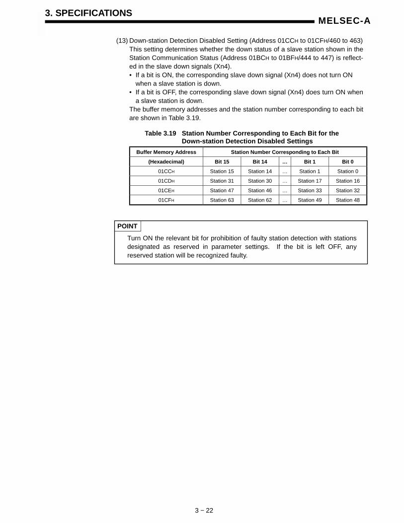
(13) Down-station Detection Disabled Setting (Address 01CCH to 01CFH/460 to 463)This setting determines whether the down status of a slave station shown in theStation Communication Status (Address 01BCH to 01BFH/444 to 447) is reflect-ed in the slave down signals (Xn4).• If a bit is ON, the corresponding slave down signal (Xn4) does not turn ON
when a slave station is down.• If a bit is OFF, the corresponding slave down signal (Xn4) does turn ON when
a slave station is down.The buffer memory addresses and the station number corresponding to each bitare shown in Table 3.19.
Table 3.19 Station Number Corresponding to Each Bit for theDown-station Detection Disabled Settings
Buffer Memory Address Station Number Corresponding to Each Bit
(Hexadecimal) Bit 15 Bit 14 … Bit 1 Bit 0
01CCH Station 15 Station 14 … Station 1 Station 0
01CDH Station 31 Station 30 … Station 17 Station 16
01CEH Station 47 Station 46 … Station 33 Station 32
01CFH Station 63 Station 62 … Station 49 Station 48
POINT
Turn ON the relevant bit for prohibition of faulty station detection with stationsdesignated as reserved in parameter settings. If the bit is left OFF, anyreserved station will be recognized faulty.

3. SPECIFICATIONS
3 − 23
MELSEC-A
(14) Parameters (Address 0154H to 034FH/340 to 847)Used to set parameters via the sequence program.The parameters set by a sequence program are written to E2PROM.Once parameters have been set, they do not require setting again until changesare made to the parameters. After DN91 is turned ON, if the E2PROM containsvalid parameters, the parameters from E2PROM are stored in the parameterareaFollow the procedure below to write new parameters.(a) Set parameters in the parameter area, as shown in Table 3.20.
(b) Turn ON the parameter set request (Y(n+1)7) with a sequence program.
(c) The set parameters are written.
Table 3.20 Parameter Set Data
Buffer MemoryAddress (16 hex)
Item Contents
01D4H Host station (MAC ID)Stores the station number (MAC ID) of DN91 in a range from 0000H to 0003H.Setting parameters with this value set at FFFFH invalidates the parameters thathave been set by the sequence program.
01D5H Baud rateSelect the baud rate:1 = 500 Kbps, 2 = 250 Kbps, 3 = 125 Kbps
01D6H, 01D7H Not used
01D8HStation number for the first slavestation
Lower byte: Station number (MAC ID) of first slave station0 to 63
Upper byte: 01H → Station that supports UCMM and uses the message group 3.02H → Station that supports UCMM and uses the message group 2.03H → Station that supports UCMM and uses the message group 1.04H → Station that does not support UCMM. (Dedicated server of
group 2)80H → Reserved station
01D9HConnection type for the firstslave station
Select the connection type for I/O communication:0001H = polling,0002H = bit strobe,0004H = change of state,0008H = cyclic
01DAHNumber of byte modules for thefirst slave station
Lower byte: Number of input byte modulesUpper byte: Number of output byte modules(8 points of bit modules are calculated as one byte module.)
01DBHNumber of word modules for thefirst slave station
Lower byte: Number of input word modulesUpper byte: Number of output word modules
01DCHNumber of double-word modulesfor the first slave station
Lower byte: Number of input double-word modulesUpper byte: Number of output double-word modules
01DDH
Expected packet rate for the firstslave station (EXPECTEDPACKET RATE)
Sets the expected packet rate at the slave station.Setting = 0000H (default) →→ 200 msSetting ≠ 0000H → The value (setting - 1) is the communication watchdog timer
setting (ms).The setting will vary depending on the connection type. Refer to Table 3.21 forfurther details of the setting.

3. SPECIFICATIONS
3 − 24
MELSEC-A
Buffer MemoryAddress (16 hex)
Item Contents
01DEH
Watchdog timeout action for thefirst slave station (WATCHDOGTIMEOUT ACTION)
Slave station watchdog timeout actionSet value = 0000H (default value)
Equal to TIMEOUT below.Set value = 0001H: TIMEOUT
Connection enters timeout status. Can only be reset by the operator stopping and restarting communication.
Set value = 0002H: AUTO DELETEConnection is automatically deleted. Communication stops and automatically restarts. Outputs are cleared to 0.
Set value = 0003H: AUTO RESETCommunication is continued with the connection maintained. Outputs are not cleared to 0.
01DFHFirst Slave Station ProductionInhibit Time
Sets the production inhibit time.Setting = 0000H (default) → 20 msSetting ≠ 0000H → The value (setting - 1) is the minimum transmission interval
(ms).The setting will vary depending on the connection type. Refer to Table 3.21 forfurther details of the setting.
01E0H to 01E7HSetting for the second slavestation
Same as with the first slave station
01E8H to 01EFH Setting for the third slave station Same as with the first slave station
01F0H to 01F7H Setting for the 4th slave station Same as with the first slave station
01F8H to 01FFH Setting for the 5th slave station Same as with the first slave station
0200H to 0207H Setting for the 6th slave station Same as with the first slave station
0208H to 020FH Setting for the 7th slave station Same as with the first slave station
0210H to 0217H Setting for the 8th slave station Same as with the first slave station
0218H to 021FH Setting for the 9th slave station Same as with the first slave station
0220H to 0227H Setting for the 10th slave station Same as with the first slave station
0228H to 022FH Setting for the 11th slave station Same as with the first slave station
0230H to 0237H Setting for the 12th slave station Same as with the first slave station
0238H to 023FH Setting for the 13th slave station Same as with the first slave station
0240H to 0247H Setting for the 14th slave station Same as with the first slave station
0248H to 024FH Setting for the 15th slave station Same as with the first slave station
0250H to 0257H Setting for the 16th slave station Same as with the first slave station
0258H to 025FH Setting for the 17th slave station Same as with the first slave station
0260H to 0267H Setting for the 18th slave station Same as with the first slave station
0268H to 026FH Setting for the 19th slave station Same as with the first slave station
0270H to 0277H Setting for the 20th slave station Same as with the first slave station
0278H to 027FH Setting for the 21st slave station Same as with the first slave station
0280H to 0287H Setting for the 22nd slave station Same as with the first slave station
0288H to 028FH Setting for the 23rd slave station Same as with the first slave station
0290H to 0297H Setting for the 24th slave station Same as with the first slave station
0298H to 029FH Setting for the 25th slave station Same as with the first slave station
02A0H to 02A7H Setting for the 26th slave station Same as with the first slave station
02A8H to 02AFH Setting for the 27th slave station Same as with the first slave station
02B0H to 02B7H Setting for the 28th slave station Same as with the first slave station
02B8H to 02BFH Setting for the 29th slave station Same as with the first slave station
02C0H to 02C7H Setting for the 30th slave station Same as with the first slave station
02C8H to 02CFH Setting for the 31st slave station Same as with the first slave station
02D0H to 02D7H Setting for the 32nd slave station Same as with the first slave station

3. SPECIFICATIONS
3 − 25
MELSEC-A
Buffer MemoryAddress (16 hex)
Item Contents
02D8H to 02DFH Setting for the 33rd slave station Same as with the first slave station
02E0H to 02E7H Setting for the 34th slave station Same as with the first slave station
02E8H to 02EFH Setting for the 35th slave station Same as with the first slave station
02F0H to 02F7H Setting for the 36th slave station Same as with the first slave station
02F8H to 02FFH Setting for the 37th slave station Same as with the first slave station
0300H to 0307H Setting for the 38th slave station Same as with the first slave station
0308H to 030FH Setting for the 39th slave station Same as with the first slave station
0310H to 0317H Setting for the 40th slave station Same as with the first slave station
0318H to 031FH Setting for the 41st slave station Same as with the first slave station
0320H to 0327H Setting for the 42nd slave station Same as with the first slave station
0328H to 032FH Setting for the 43rd slave station Same as with the first slave station
0330H to 0337H Setting for the 44th slave station Same as with the first slave station
0338H to 033FH Setting for the 45th slave station Same as with the first slave station
0340H to 0347H Setting for the 46th slave station Same as with the first slave station
0348H to 034FH Setting for the 47th slave station Same as with the first slave station
0350H to 0357H Setting for the 48th slave station Same as with the first slave station
0358H to 035FH Setting for the 49th slave station Same as with the first slave station
0360H to 0367H Setting for the 50th slave station Same as with the first slave station
0368H to 036FH Setting for the 51st slave station Same as with the first slave station
0370H to 0377H Setting for the 52nd slave station Same as with the first slave station
0378H to 037FH Setting for the 53rd slave station Same as with the first slave station
0380H to 0387H Setting for the 54th slave station Same as with the first slave station
0388H to 038FH Setting for the 55th slave station Same as with the first slave station
0390H to 0397H Setting for the 56th slave station Same as with the first slave station
0398H to 039FH Setting for the 57th slave station Same as with the first slave station
03A0H to 03A7H Setting for the 58th slave station Same as with the first slave station
03A8H to 03AFH Setting for the 59th slave station Same as with the first slave station
03B0H to 03B7H Setting for the 60th slave station Same as with the first slave station
03B8H to 03BFH Setting for the 61st slave station Same as with the first slave station
03C0H to 03C7H Setting for the 62nd slave station Same as with the first slave station
03C8H to 03CFH Setting for the 63rd slave station Same as with the first slave station

3. SPECIFICATIONS
3 − 26
MELSEC-A
Table 3.21 Details of Expected Packet Rate and Production Inhibit Time
Expected Packet Rate Production Inhibit Time
(1) Set the communication watchdog timer value for a slave station. Any interruption of communication between the master and slave stations for the time setting, the slave station executes the action designated by the Watchdog Timeout Action.
(1) Set the minimum transmission interval, or the minimum time a slave can get the transmission dataready.The master station sends the polling request at this interval.
(2) When the expected packet rate setting ≠ 1,or the expected packet rate ≠ 0 ms,
it must be the Expected packet rate ≥ the Production inhibit time.
Polling
(3) When the setting value = 1, or when the Expected packet rate = 0 ms, the Watchdog timer monitoring is disabled.
(1) Set the communication watchdog timer value for a slave station. Any interruption of communication between the master and slave stations for the time setting, the slave station executes the action designated by the Watchdog Timeout Action.
(1) Set the minimum transmission interval, or the minimum time a slave can get the transmission dataready.The master station sends the polling request at this interval.
(2) When the expected packet rate setting ≠ 1,or the expected packet rate ≠ 0 ms,
it must be the Expected packet rate ≥ the Production inhibit time.
Bit strobe
(3) When the setting value = 1, or when the Expected packet rate = 0 ms, the Watchdog timer monitoring is disabled.
(3) This value must be the same for all bit strobe connections.
Change of state(1) Always set the value = 1 or, in other word, set the
expected packet rate = 0 ms.(1) Always set the value = 1, or set the production
inhibit time = 0 ms.
(1) Designate the data transmission interval from a slave station to the master station.
(1) Designate the data transmission interval from the master station to slave stations.
(2) When the expected packet rate setting ≠ 1,or the expected packet rate ≠ 0 ms,
it must be the Expected packet rate ≥ the Production inhibit time.Cyclic
(3) The setting value = 1 or the Expected packet rate= 0 ms is prohibited.
(3) The setting value = 1 or the Production inhibit time= 0 ms is prohibited.

4. FUNCTIONS
4 − 1
MELSEC-A
4. FUNCTIONS
This section describes the functions.The DN91 offers the following two types of functions. Proper parameter setting isrequired in advance.• I/O communication functions (see Section 4.1)• message communication functions (see Section 4.2)
4.1 I/O Communication Functions
The I/O communication functions conduct I/O data communication with the slavestations.The I/O communication functions allow the communication type to be set to matchthe slave station specification. Four connection types are available: polling, bitstrobe, change of state, and cyclic. The connection type can be set usingparameters.
[Parameter Set]
1) Write parameters onto the "Parameter" area of the buffer memory, and turn ONthe parameter setting request (Y(n+1)1) via the sequence program to set theparameters.When the parameters are successfully written, the Parameter Setting Complete(Xn7) automatically turns ON.Once the parameters are set, no subsequent parameter setting is required aslong as no change in the parameters is necessary.When setting the parameters via the configuration software, do not use thesequence program to set the parameters.
Slave stationDN91PLC CPU
SET Y(n+1)7
007FH
5)
1)
2)
4)
6)
3)0000H
InputIinput dataarea
Refreshing
Refresh request
Parameter set
Xn1Refreshing
Xn1Refreshing
Xn7 Parameter set complete
00FFH
0080H
OutputOutput dataarea
FROM
TO
SET Y(n+1)1Refresh command

4. FUNCTIONS
4 − 2
MELSEC-A
[Refresh]
2) Communication with the slave stations starts when the refresh request signal(Y(n+1)1) turns ON.
[Input Data]
3) The input status of each slave station is automatically stored in the input dataarea of the DN91 buffer memory.
4) The input statuses stored in the input data area of the buffer memory are read tothe PLC CPU using sequence program FROM instruction.
[Output Data]
5) The ON/OFF information output to the slave stations is written to the output dataarea of the buffer memory using the sequence program TO instruction.
6) The ON/OFF information stored in the output data area of the buffer memory isautomatically output to the slave stations.

4. FUNCTIONS
4 − 3
MELSEC-A
4.2 Message Communication Functions
The message communication functions read and write data to the slave stationspecial area.
4.2.1 Get attribute
1) Set "Get Attribute" in the buffer memory message communication commandarea using the sequence program TO instruction.
2) Turn ON message communication request (Y(n+1)2) with a sequence programto send the data set in the buffer memory message communication commandarea to the slave stations and start message communication.
3) DN91 receives data from the slave stations and processes it as follows:• The slave station special data set in the message communication command
area is stored in the message communication data area of the buffer memory.• The result of processing the message communication is stored in the
message communication results area of buffer memory.4) When the process result is stored in the message communication results area of
buffer memory, message communication ends and the message communicationcomplete (Xn2) signal automatically turns ON.
5) When the slave station data ends normally in the buffer memory messagecommunication area, it is read to the PC CPU using the sequence programFROM instruction.
Slave station (MAC ID)DN91PC CPU
Class
Instance
Message communi-cation request
Attribute
Xn2Message communicationcomplete
FROM
SET Y(n+1)2
TO
Message communi-cation complete
Iinstance
Attribute
Class
Instance
Instance
Attribute
Attribute
Attribute
Attribute
Xn2FROM
0110H
011FH
Messagecommunicationcommand area
Messagecommunication
result area
Messagecommunication
data area
0130H
01A7H
0120H
012FH
2)
1) 2)
3)
5)
4)
Attribute

4. FUNCTIONS
4 − 4
MELSEC-A
4.2.2 Set attribute
1) Set "Set Attribute" in the buffer memory message communication commandarea using the sequence program TO instruction.
2) Set the data to be written in the buffer memory message communication dataarea using the sequence program TO instruction.
3) Turn ON message communication request (Y(n+1)2) to write the data stored inthe buffer memory message communication data area to the special area of theslave station set by the message communication command area.
4) When the write operation is complete, the message communication result isstored in the message communication results area of buffer memory.
5) When the process result is stored in the message communication results area ofbuffer memory, message communication ends and the message communicationcomplete (Xn2) signal automatically turns ON.
Slave station (MAC ID)
Class
Iinstance
DN91PC CPU
Message communi-cation request
Attribute
Attribute
Xn2Message communicationcomplete
Followingprocesses
SET Y(n+1)2
TO
Message communi-cation complete
Class
Instance
Instance
Attribute
Attribute
Attribute
TO
Class
Instance
Attribute
Attribute
Instance
Attribute
0110H
011FH
Messagecommunicationcommand area
Messagecommunication
result area
Messagecommunication
data area
0130H
01A7H
0120H
012FH
1)
2)
3)
4)
5)

4. FUNCTIONS
4 − 5
MELSEC-A
4.2.3 Read communication error information
1) Set "Read Communication Error Information" in the buffer memory messagecommunication command area using the sequence program TO instruction.
2) Turn ON message communication request (Y(n+1)2) with a sequence programto read the accumulated error information from the relevant slave stations to theDN91.
3) DN91 receives data from the slave stations and processes it as follows:• The slave station error information set in the message communication
command area is stored in the message communication data area of thebuffer memory.
• The result of processing the message communication is stored in themessage communication results area of buffer memory.
4) When the process result is stored in the message communication results area ofbuffer memory, message communication ends and the message communicationcomplete (Xn2) signal automatically turns ON.
5) The slave station communication error information stored in the buffer memorymessage communication data area is read to the PC CPU using the sequenceprogram FROM instruction.
3)
*: Stores the status of each slave station during I/O communication.
Slave station (MAC ID)
Class 1
Instance
I/OCommuni-
cation
DN91
0110H
011FH
PC CPU
Message communi-cation request
Messagecommunicationcommand area
Slave informationstorage area*
Messagecommunication
result area
Messagecommunication
data area
Attribute
Attribute
Xn2Message communicationcomplete
FROM
SET Y(n+1)2
TO
Message communi-cation complete
Instance
Class
Instance
Instance
Attribute
Attribute
Attribute
Attribute
Attribute
Attribute
Attribute
Xn2FROM
0130H
01A7H
0120H
012FH
1)
2)
4)
5)

5. SETTINGS AND PROCEDURES BEFORE OPERATION
5 − 1
MELSEC-A
5. SETTINGS AND PROCEDURES BEFORE OPERATION
This section describes the procedure before start-up of a system using DN91.
5.1 Settings and Procedures
5.1.1 DN91 start-up procedure when setting parameters with a sequence program
Develop a parameter-setting sequence program.
Connect the DeviceNet cable.
Mount DN91 on the base unit, and power ON the unit.(Set the CPU key switch to STOP, and do not connect theDeviceNet cable.)
Set the CPU key switch to RUN. (Parameter setting completes.)
Set the CPU key switch to STOP, and turn OFF the power.
Parameter settingsuccessfullycompleted?
Write the parameter-setting sequence program.
YES
NO
Refer to Section 6.3 and Section 7.
Start
Modify the para-meter-setting se-quence program.
Power ON the unit. (Set the CPU key switch to STOP.)
Power ON the DeviceNet network and slave stations.
Set the CPU keyswitch to RUN.
Modify the para-meter-setting se-quence program.
Set the CPU keyswitch to STOP.
Yes
No"Communication
error code"area = 0?
(Monitor the buffer memoryto check it.)
Develop a control sequence program
Set the CPU key switch to RUN.
Write the control sequence program onto the PLC CPU.Modify the cont-rol sequence pro-gram.
Operates normally?No
Operation
Yes

5. SETTINGS AND PROCEDURES BEFORE OPERATION
5 − 2
MELSEC-A
5.1.2 DN91 start-up when setting parameters with the configuration software
Mount DN91 on the base unit, and power ON the unit.(Set the CPU key switch to STOP, and do not connect theDeviceNet cable.)
Prepare parameters with the configuration software.
Obtain EDS file for the slave station used from the manufacturerof the station.
Power OFF the unit.
Copy the EDS file onto the EDS storage folder of the configurationsoftware. (If, for example, the software is installed in the folder"Program Files" of drive C, copy the file onto C:/ProgramFiles/Hilscher GmbH/SyCon/Fieldbus/DEVNet/EDS.)
Write the parameters onto DN91.
Start
Power ON the DeviceNet network and slave stations.
Connect the DeviceNet network cable.
Write the parame-ters onto DN91.
Modify the para-meters with theconfiguration soft-ware. Yes
No"Communication
error code"area = 0?
(Monitor the buffer memoryto check it.)
Develop a control sequence program.
Set the CPU key switch to RUN.
Write the control sequence program onto the PLC CPU.Modify the cont-rol sequence pro-gram.
Operates normally?No
Operation
Yes
Refer to Section 6.4.
Power ON the unit. (Set the CPU key switch to STOP.)

5. SETTINGS AND PROCEDURES BEFORE OPERATION
5 − 3
MELSEC-A
5.2 Mounting and Installation
This section describes handling instructions of the DN91 unit between unpackingand installation and the unit installation environment.For details about the DN91 unit mounting and installation, see the users manual forthe PLC CPU unit being used.
5.2.1 Handling instructions
This section describes handling instructions related to the DN91.(1) The unit casing and terminal block are made of plastic. Do not drop the unit or
apply strong shocks to it.
(2) Do not remove the printed circuit board from the unit casing.This can cause faults.
(3) During wiring operations, take care that no wiring offcuts or other foreign mattergets inside the unit.Clean out any foreign matter that does get inside the unit.
(4) Tighten the unit mounting screws and terminal screws in the torque rangesspecified below.
Type of ScrewTightening Torque RangeN ⋅⋅⋅⋅ cm (kg ⋅⋅⋅⋅ cm) [lb ⋅⋅⋅⋅ inch]
A1SJ71DN91 Module mounting screw 78 to 118 (8 to 12) [6.93 to 10.48]
DeviceNet Connector screw 35.3 to 48.0 (3.6 to 4.9) [3.13 to 4.26]
DeviceNet Connector wire screw 60.8 to 82.3 (6.2 to 8.3) [5.40 to 7.31]
5.2.2 Installation environment
Do not mount an A Series PC under in the following environments:(1) Locations where the ambient temperature is outside the range 0 to 55 °C.
(2) Locations where the ambient humidity is outside the range 10 to 90 %.
(3) Locations where condensation occurs due to sudden temperature fluctuations.
(4) Locations where corrosive or flammable gases exist.
(5) Locations with a high level of conductive dust or iron filings, oil mist, salt, ororganic solvent.
(6) Locations exposed to direct sunlight.
(7) Locations subject to strong electric or magnetic fields.
(8) Locations where vibrations or shocks are directly transmitted to the unit.

5. SETTINGS AND PROCEDURES BEFORE OPERATION
5 − 4
MELSEC-A
5.3 Nomenclature
This section describes the AJ71DN91 and A1SJ71DN91 parts.
AJ71DN91
A1SJ71DN91
RS-232-C
A1SJ71DN91
RUN
L.RUN
MS
NS
DeviceNet
AJ71DN91
RUN
L.RUN
NS
MS
RS-232-C
DeviceNet
DeviceNet connector
RS-232C connector
DeviceNet connector
RS-232C connector

5. SETTINGS AND PROCEDURES BEFORE OPERATION
5 − 5
MELSEC-A
AJ71DN91
RUN
L.RUN
NS
MS
A1SJ71DN91
RUN
L.RUN
MS
NS
5.4 LED Displays and Indicator Descriptions
This section describes the names of the LEDs at the top of the AJ71DN91 andA1SJ71DN91 front panel and provides indicator descriptions.
LEDName
Color Description LED Display Status
Lit Normal operation
Unit error detected
No power supply
Not lit
Parameters being loaded
Unit error detected
RUN Red Normal opera-tion display
Flashing
Parameters being loaded
Lit Communicating
Not lit Communication stopped
Flashing (periodic) Preparing for communication
L.RUN Red Communicationstatus display
Flashing (random) Communication parameter error
Lit DeviceNet interface unitoperating normally
Green Module statusdisplay
Flashing Parameter error
MS
Red Module statusdisplay
Not used
Lit Communication enabled with on-line slave stations
Green Network statusdisplay
Flashing Communication not enabled withon-line slave stations
Duplicate MAC ID errorLit
Bus-off error occurred
NS
Red Network statusdisplay
Flashing There is a connection that hastimed out.

5. SETTINGS AND PROCEDURES BEFORE OPERATION
5 − 6
MELSEC-A
5.5 Connecting Communication Cable to DN91
(1) Connecting communication cablesThis section describes how to connect the communication cable to the DN91.
The DN91 DeviceNet connector is shown in the diagram above. The side of theconnector is color-coded with the corresponding cable lead colors.Connect the communication cable, ensuring that each cable lead color matchesthe marking on the connector.
(2) Grounding the networkDeviceNet network is to be grounded at a single point.And select a point for grounding in the vicinity of the center of the network.Connect a cable shield (drain wire) to the ground of the power supply unit forClass-D (Class-3) grounding.If the network contains multiple power supply units, ground a unit that ispositioned near the center of the network and do not ground at any otherpositions. When using multiple power supply units, use power taps.
Power tapPower tap
(near the center of the network) Power tap
V+
CAN_L
V-
CAN_H
Shield (drain wire)
Power supply unit
FG V+ V-
Power supply unit
FG V+ V-
Power supply unit
FG V+ V-
V+ (red)
CAN_H (white)
CAN_L (blue)
V- (black)
Shield (drain wire)

5. SETTINGS AND PROCEDURES BEFORE OPERATION
5 − 7
MELSEC-A
5.6 Instructions for Connecting the Network Power Supply
This sections describes the instructions for connecting the network power supply.
5.6.1 Network power supply unit installation position
Follow the procedure below to determine the position to install the network powersupply unit.1) Calculate the current consumption of the stations required on the network.2) Measure the total length of the network.3) Refer to Tables 5.1 and 5.2 to determine the maximum current capacity
corresponding to the network length and type of cable used.4) If the current value calculated at step 1) is less than the current value calculated
at step 3), any of the network power supply unit installation positions describedin Section 5.6.2 can be used.
5) If the current value calculated at step 1) exceeds the current value calculated atstep 3), refer to Section 5.6.2 to determine whether the network power supplyunit can be installed near the center of the network to supply power to allstations.
6) If the results from step 5) indicate that power cannot be supplied to all stations,increase the number of network power supply units.
Table 5.1 Maximum Current Capacity Corresponding tothe Network Length of Thick Cable
Network length (m) 0 25 50 100 150 200 250 300 350 400 450 500
Maximum current (A) 8.00 8.00 5.42 2.93 2.01 1.53 1.23 1.03 0.89 0.78 0.69 0.63
Table 5.2 Maximum Current Capacity Corresponding tothe Network Length of Thin Cable
Network length (m) 0 10 20 30 40 50 60 70 80 90 100
Maximum current (A) 3.00 3.00 3.00 2.06 1.57 1.26 1.06 0.91 0.80 0.71 0.64
POINT
Use a network power supply unit with a current capacity exceeding therequired total current consumption.

5. SETTINGS AND PROCEDURES BEFORE OPERATION
5 − 8
MELSEC-A
5.6.2 Calculating network power supply unit installation position and current capacity
This section describes the calculating network power supply unit installation positionand current capacity.
(1) Network power supply unit connected to an end of the networkThe current capacity is calculated as shown below when the network powersupply unit is connected to the end of a thick-cable network with a total length of200 m.
Total power supply distance = 200 mTotal current capacity = 0.1 A + 0.15 A + 0.05 A + 0.25 A + 0.1 A = 0.65 AMax. current capacity of 200 m of thick cable (from Table 5.1) = 1.53 A
Therefore, this configuration allows power supply to all stations.
(2) Network power supply unit connected to the center of the networkThe current capacity is calculated as shown below when the network powersupply unit is connected at the center of a thick-cable network.In this case, the network power supply unit can supply twice the currentcompared to when it is connected to the end of the network.
Power supply distance left of the network power supply unit = power supplydistance right of the network power supply unit = 120 mTotal current capacity to the left = 0.1 A + 0.25 A + 0.2 A = 0.55 ATotal current capacity to the right = 0.15 A + 0.25 A + 0.15 A = 0.55 AMax. current capacity of 120 m of thick cable (from Table 5.1) = approx. 2.56 A(Linearly interpolated between 100 m and 150 m.)
Therefore, this configuration allows power supply to all stations.
Terminationresistance
Networkpower supply
unit
0.1A 0.15A 0.05A 0.25A 0.1A
200m
master Slave station Slave station Slave stationSlave station
Terminationresistance
Master
120m
Terminationresistance
Terminationresistance
0.1A 0.25A 0.2A 0.25A 0.15A
120m
Slave station Slave station Slave stationSlave station
0.15A
Slave station
Networkpower supply
unit
Master

5. SETTINGS AND PROCEDURES BEFORE OPERATION
5 − 9
MELSEC-A
(3) Remedy for Insufficient Network Power Supply Current CapacityIf the network power supply unit is connected to a thick-cable network, asshown below.
Power supply distance left of the network power supply unit = power supplydistance right of the network power supply unit = 120 mTotal current capacity to the left = 1.1 A + 1.25 A + 0.5 A = 2.85 ATotal current capacity to the right = 0.25 A + 0.25 A + 0.85 A = 1.35 AMax. current capacity of 120 m of thick cable (from Table 5.1) = approx. 2.56 A(Linearly interpolated between 100 m and 150 m.)
In this configuration, the current capacity to the left of the network power supplyunit is insufficient.If this type of situation occurs, move the network power supply unit in thedirection of insufficient current capacity (to the left in the diagram above).
Total power supply distance left of the network power supply unit = 100 mTotal power supply distance right of the network power supply unit = 140 mTotal current capacity to the left = 1.1 A + 1.25 A = 2.35 ATotal current capacity to the right = 0.5 A + 0.25 A + 0.25 A + 0.85 A = 1.85 AMax. current capacity of 100 m of thick cable (from Table 5.1) = approx. 2.93 AMax. current capacity of 140 m of thick cable (from Table 5.1) = approx. 2.19 A(Linearly interpolated between 100 m and 150 m.)
As a result of shifting the network power supply unit in the direction of insuffi-cient current capacity, it is able to supply power to all stations.
120m120m
Terminationresistance
Terminationresistance
1.1A 1.25A 0.5A 0.25A 0.85A
Master station Slave station Slave station Slave stationSlave station
0.25A
Slave station
Networkpower supply
unit
100m 140m
Terminationresistance
Terminationresistance
1.1A 1.25A 0.5A 0.25A 0.85A
Master Slave station Slave station Slave stationSlave station
0.25A
Slave station
Networkpower supply
unit

5. SETTINGS AND PROCEDURES BEFORE OPERATION
5 − 10
MELSEC-A
(4) Mixed Trunk Line and Drop LineThe current capacity is calculated as shown below when the network powersupply unit is connected to a network with 200 m of thick-cable trunk line and6 m of thin-cable drop line.
Thick-cable power supply distance = 200 mDrop line power supply distance = 6 mTotal current capacity = 0.5 A + 0.15 A + 0.05 A + 0.25 A + 0.1 A = 1.05 AMax. current capacity of 200 m of thick cable (from Table 5.1) = 1.53 AMax. current capacity of 6 m of drop line (from Table 5.3) = 0.75 ATotal current of devices connected to drop line = 0.1 A
Therefore, this configuration allows power supply to all stations.
Table 5.3 Maximum Current Capacity Corresponding tothe Drop Line Length
Drop line length (m) 0.30 0.90 1.50 2.25 3.00 4.50 6.00
Max. current (A) 3.00 3.00 3.00 2.00 1.50 1.00 0.75
Slave station
0.1A
Networkpower supply
unit
Terminationresistance
Terminationresistance
1.0A 0.15A 0.05A 0.25A
Master station スレーブ Slave stationSlave station Slave station
200m

6. PARAMETER SETTINGS
6 − 1
MELSEC-A
6. PARAMETER SETTINGS
This section describes the parameter settings required for DN91 operation.The following two methods are available to set the parameters: Parameters that have been set are stored in separate areas on E2PROM withinDN91. Once the parameters are set, no subsequent parameter setting is required aslong as no change in the parameters is necessary.• Setting with a sequence program (see Section 6.3)• Setting with the configuration software (see Section 6.4)
6.1 Settings Parameter
The parameters may be set by the following two methods:• Use TO command of the sequence program to set the parameters.• Use the configuration software to set the parameters.
The following discusses the parameter-setting methods.
(1) Parameter setting by the sequence programThe sequence program-based parameter setting includes the followingcontents:
1) Host station number (MAC ID of the host station)2) Baud rate3) Station number of the n-th unit4) Connection type of the n-th slave station5) Number of byte modules for the n-th slave station6) Number of word modules for the n-th slave station7) Number of double-word modules for the n-th slave station8) Expected packet rate for the n-th slave station9) Watchdog timeout action for the n-th slave station
10) Production inhibit time for the n-th slave station
The setting of above-shown items 3) to 10) may be done for 63 units.
To construct a network of DeviceNet that contains DN91 as the master, settingstation numbers (MAC IDs) is required for DN91 and slave stations. Station numbers available for them are 0 to 63, and any numbers may be used forDN91 and slave stations as long as they do not mutually overlap. Refer to the operation manual of the slave station for the procedure of setting stationnumbers (MAC IDs) of the slave stations.
For the procedure and details of setting parameters through the sequence program,refer to Section 7.3 “Setting Parameters with a Sequence Program” and 3.4.2 (14)“Buffer Memory”.
(2) Parameter setting by the configuration softwareThe Configuration software-based parameter setting includes the followingcontents:
1) Setting configuration2) Master parameter setting3) Bus parameter setting4) Device (slave) parameter setting
For the procedure and details of setting parameters with the configuration software,refer to Section 6.4 “Setting Parameters with the Configuration Software”.

6. PARAMETER SETTINGS
6 − 2
MELSEC-A
6.2 Important Points about the Parameter Settings
Setting the address mode to the byte address using the configuration software mayresult in the division of a word data into upper and lower bytes and may be stored inseparate addresses of the buffer memory. For that reason, data processing by the sequence program may be required.
REMERK
See the slave station manual for details about the slave station data transfer specifications.
6.3 Setting with a Sequence Program
See the following sections for the methods of setting parameters with a sequenceprogram: 3.3.2 (6) I/O Signal Details, 3.4.2 (14) Parameters, 7.3 SettingParameters with a Sequence Program.
POINT
Avoid any setting that validates both parameter setting procedures of usingthe sequence program and of using configuration software.1) Setting parameters with the sequence program erases the parameter
settings that have been set with the configuration software.2) When using the configuration software to set the parameters, follow the
setting procedure as shown below:• Set the parameters, referring to 6.4 Setting Parameters with the Configuration
Software.• To invalidate the settings that have been set with the sequence program, use
the sequence program to write FFFFH onto the host station number (01D4H)of the buffer memory and turn ON the parameter-setting request (Y(n+1)7).

6. PARAMETER SETTINGS
6 − 3
MELSEC-A
6.4 Setting Parameters with the Configuration Software (Parameter Setting Tool)
This system gives an outline of the setting method using the configuration software.While the following explanations are based on screens of SyCon Ver. 2.0.6.2, thescreen hierarchy and items of the setting are subject to change due to potentialchanges in the specifications of the configuration software. Refer to the operationmanual of the configuration software for the latest information.
The following four steps are required to set the DN91 parameters:1) Set configuration2) Set master parameters3) Set bus parameters4) Set device (slave) parameters
6.4.1 Setting configuration
Set the DeviceNet network configuration on the screen below.

6. PARAMETER SETTINGS
6 − 4
MELSEC-A
6.4.2 Setting master parameters
Set the master parameters on the screen below.
Set the items as follows:
1) Startup behavior after system initializationSelect "Controlled release of the communication by the application program."
2) User program monitoringThis is the time to monitor whether the DN91 is operating normally (units: 1msec).Set a value of 30 msec, or higher.
3) Addressing modeSelect byte addressing or word addressing as the addressing mode.
4) Storage formatDesignate the data format of the word data.Select "Little Endian."
5) Handshake of the process dataSelect buffered or device controlled.
6) Hardware parameterSelect "8 KB dual-port memory."

6. PARAMETER SETTINGS
6 − 5
MELSEC-A
6.4.3 Setting bus parameters
Set the bus parameters on the screen below.
Set the items as follows:
1) BaudrateSelect one of the following baud rate settings:
• 125 Kbit/s (125 kbaud)
• 250 Kbit/s (250 kbaud)
• 500 Kbit/s (500 kbaud)
2) MAC ID MasterSet the DN91 station number as a value from 0 to 63.
3) Heartbeat TimeoutSet the interval for checking any existence of slave stations.
4) Auto clear mode onSet to turn OFF, or not, output to all stations in case an error occurs with any single station.

6. PARAMETER SETTINGS
6 − 6
MELSEC-A
6.4.4 Set the device (slave station) parameters
Set the slave station parameters on the screen below.
Set the items as follows:
1) MAC IDSet the slave station number as a value from 0 to 63.
2) DescriptionEnter a name for the slave station.
3) Activate device in actual configurationSet whether the station is an actively communicating station or a reservedstation.
• Checked : Actively communicating station
• Not checked : Reserved station
4) Actual chosen IO connectionSelect the I/O data communication type: Polling, bit strobe, change of
state, or cyclic.
5) UCMM checkSet if a slave station has the UCMM functionality or not. If it does, also set themessage group that is used for message communication.
6) Fragmented TimeoutSet the time for waiting for the acknowledgement of receipt from a slave stationfor the case of divided message transmission and receipt.
7) Expected packet rateSet the expected packet rate.See 3.4.2(14) Parameters for details about the settings.
8) Production inhibit timeSet the production inhibit time.See 3.4.2(14) Parameters for details about the settings.

6. PARAMETER SETTINGS
6 − 7
MELSEC-A
9) Watchdog timeout actionSet the action on a watchdog timeout.See 3.4.2(14) Parameters for details about the settings.
10) Configured I/O connection data and its offset addressSet the I/O module configuration. Also, set I. Addr and O. Addr to the DN91 buffer memory address allocated to the I/O module I/O data.

7. PROGRAMMING
7 − 1
MELSEC-A
7. PROGRAMMING
This section describes how to create programs.
7.1 Important Points about Programming
Follow the points below when creating a program.
(1) Creating a Slave Station I/O Communication Program
• Place the I/O communication reading program at the beginning of thesequence program.
• Place the I/O communication writing program at the end of the sequenceprogram.
(2) Read received data and write send data when no unit error has occurred andthe unit is in ready status.
(3) Create a program to detect the communication status of each station and applyan interlock. Also, create processing programs to handle faults.
(4) In case parameter setting has been done previously with the sequenceprogram, the settings are stored in the buffer memory when powered ON.To set the parameters from the scratch, clear the "Parameter" area of the buffermemory to zero(0).
X0 X0FCommunication program
Unit error Unit ready
X0 X0F
Unit error Unit ready
M0Station number 0 error processing program
K4M0H1BCH0FROM K4
M1Station number 1 error processing program
M0Station number 0 normal processing program
M1Station number 1 normal processing program
Slave communication status
Refresh processing request, I/O communication read program
I/O communication write program

7. PROGRAMMING
7 − 2
MELSEC-A
7.2 System Configuration
The program described in this section is based on the system described below.1) DN91 is set to station number 5, the first sensor is set to station number 1, and
the second remote I/O is set to station number 0.2) Bit strobe communication is used between DN91 and station number 5.
Polling communication is used between DN91 and the remote I/O.3) Input data is assigned from X100 to X117 and output data is assigned from Y100
to Y10F.Sensor : Inputs X100 to X117Remote I/O : Inputs X100 to X117
: Outputs Y100 to Y10F4) The communication status of each station is stored in M0 and M1.5) If an error occurs, the error information is read to D500, the station number where
the error occurred to D501, and the error code to D502.6) Message communication write attribute data is set in D30 to D39.7) DN91 is mounted in slot 0 of the main base unit.
*: The Flex I/O DeviceNet adapter by Rockwell Automation Japan has 2-byte input data.Both IB16 and OB16 have 2-byte input data and 2-byte output data.
Station number 4Rockwell Automation Japan
Flex I/O DeviceNet adapter + 16-point input(1794ADN + IB16)
PollingBit strobe
X100 to X10F : Input dataY100 to Y10F : Output dataM3, M4 : Communication status of each stationD500 : Error informationD501 : Station number where error occurredD502 : Error codeD30 : Write attribute data
A(1S)J71DN91station number 1
Station number 3Rockwell Automation Japan
Flex I/O DeviceNet adapter + 16-point input(1794ADN + OB16)

7. PROGRAMMING
7 − 3
MELSEC-A
The relationship between the PLC CPU, master station buffer memory, first slavestation (remote I/O), and second slave station (remote I/O) is shown below.
Y10F to Y100
X10F to X100
DN91 master station
FROM
PLC CPU
Input data
Output 15 to output 00
Output data
Remote I/O (station number 3)16-point output
0001H
0003H
0002H
0000H
0080H
0081H
Status
Input 15 to input 00
Remote I/O (station number 4)16-point input
Dummy output
I15 to 00
Status
O15 to O00
Dummy outputTO
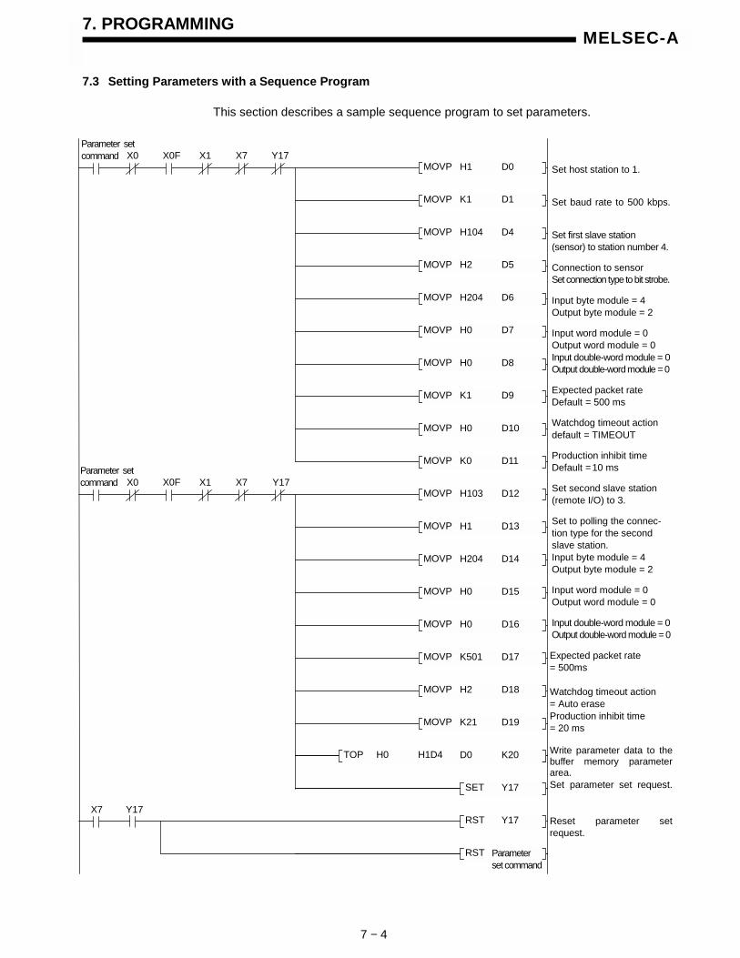
7. PROGRAMMING
7 − 4
MELSEC-A
7.3 Setting Parameters with a Sequence Program
This section describes a sample sequence program to set parameters.
Set host station to 1.
Set baud rate to 500 kbps.
Set first slave station(sensor) to station number 4.
Connection to sensorSet connection type to bit strobe.
Input byte module = 4Output byte module = 2
Input word module = 0Output word module = 0Input double-word module = 0Output double-word module = 0
Expected packet rateDefault = 500 ms
Watchdog timeout actiondefault = TIMEOUT
Production inhibit timeDefault = 10 ms
Set second slave station(remote I/O) to 3.
Set to polling the connec-tion type for the secondslave station.Input byte module = 4Output byte module = 2
Input word module = 0Output word module = 0
Input double-word module = 0Output double-word module = 0
Expected packet rate= 500ms
Watchdog timeout action= Auto eraseProduction inhibit time= 20 ms
Write parameter data to thebuffer memory parameterarea.Set parameter set request.
Reset parameter setrequest.
Y17H1MOVP D0
K1MOVP D1
H104MOVP D4
H2MOVP D5
H204MOVP D6
X0 X0F X1 X7
H0MOVP D7
H0MOVP D8
K1MOVP D9
H0MOVP D10
K0MOVP D11
Y17H103MOVP D12
H1MOVP D13
H204MOVP D14
H0MOVP D15
H0MOVP D16
X0 X0F X1 X7
K501MOVP D17
H2MOVP D18
K200MOVP
D19D0H1D4H0TOP K20
SET Y17
RST Y17
RST Parameterset command
K21MOVP D19
Y17X7
Parameter setcommand
Parameter setcommand

7. PROGRAMMING
7 − 5
MELSEC-A
The relationship between PLC CPU and master station buffer memory and themeaning of buffer memory data is shown below.
← Stores host station number 1
← Stores baud rate = 500 kbaud
← Unused
← Unused
← Stores station number of first slave station = 4
← Stores connection type of first slave station = bit strobe
← Stores input/output byte modules of first slave station
← Stores input/output word modules of first slave station
← Stores input/output double-word modules of first slave station
← Set expected packet rate of first slave station to default value
← Stores watchdog timeout action type of first slave station = TIMEOUT
← Set production inhibited time of first slave station to default value
← Stores station number of second slave station = 3
← Stores connection type of second slave station = polling
← Stores input/output byte modules of second slave station
← Stores input/output word modules of second slave station
← Stores input/output double-word modules of second slave station
← Stores expected packet rate of second slave station = 500 ms
← Stores watchdog timeout action type of second slave station =
← Stores production inhibited time of second slave station = 20 ms
PLC CPU
TOD0
Buffer memory
H101D4H
D1 K101D5H
D2 −01D6H
D3 −01D7H
D4 H10401D8H
D5 H201D9H
D6 H20401DAH
D7 H001DBH
D8 H001DCH
D9 K001DDH
D10 H001DEH
D11 K001DFH
D12 H10301E0H
D13 H101E1H
D14 H20401E2H
D15 H001E3H
D16 H001E4H
D17 K50101E5H
D18 H201E6H
D19 K2101E7H
AUTO DELETE

7. PROGRAMMING
7 − 6
MELSEC-A
7.4 I/O Communication with Slave Stations
This section describes a sample sequence program to conduct I/O communication.
7.4.1 Reading slave station I/O data
Parameter request program
7.4.2 Writing slave station I/O data
X0F
M4
M4
X1
X0F
X101
Parameter settingprogram (see Section 7.3)
Output data initial valuesettingRefresh request
Read communicationstatus
Read input data
Parameter setting program
M3
X0F X1
Parameter settingprogram (see Section 7.3)
Refresh request program(see Section 7.4.1)
Write output data
Parameter setting program
Refresh request program
Y100
K4Y100H81H0TO K1
Station number 3 output data processing program
Y102
Y103
Y105
Y107
M3
X0 X0FRefreshcommand
Station number 4 error processing program
Station number 4 input data processing program
X100
X1
K4Y100H80H0TOP K1
K4M0H1BCH0FROM K4
Y11
K4X100H1H0FROM K1

7. PROGRAMMING
7 − 7
MELSEC-A
7.5 Message Communication
This section describes a sample sequence program to conduct messagecommunication.
7.5.1 Message communication - reading
The following sample program represents a case of reading attributes of expectedpacket rate for the polling connection from the station number 3.
WritingReadattributes X0
Set attribute readcommand
Station number 3 slave stationClass ID =5
Instance ID = 2
Attribute ID = 9
Write request data tobuffer memory
Set messagecommunication request
Read result from buffermemory
Calculate read length ofreceived data
Read received data
Reset messagecommunication request
Error processing program
X0F X2 Y12
X2 Y12Reading
Reading
H101MOVP D0
D0H110H0TOP K4
H0503MOVP D1
K2MOVP D2
K9MOVP D3
D10H120H0FROMP K5
SET Reading
SET Y12
K0<> D11
K0= D11 DECP D14
K2D14/P D14
INCP D14
D14MOVP Z
D20H130H0FROMP K0Z
RST Y12
RST
RST Readattributes

7. PROGRAMMING
7 − 8
MELSEC-A
7.5.2 Message communication - writing
The following sample program represents a case of writing attributes of expectedpacket rate for the polling connection from the station number 3.
Reading X0
Write send data to buffermemory
Set attribute writecommand
Station number 3 slave stationClass ID = 5
Instance ID = 2
Send data byte length=2Attribute ID =9
Write request data tobuffer memory
Set messagecommunication request
Read result from buffermemory
Reset messagecommunication request
Error processing program
X0F X2 Y12
X2 Y12Writing
Writing
H102MOVP D0
D0H110H0TOP K4
H0503MOVP D1
K2MOVP D2
H209MOVP D3
D10H120H0FROMP K6
SET Writing
K0<> D11
RST Y12
RST
RST Writeattributes
D30H130H0TOP K1
ReadingWriteattributes
Writeattributes
K1000MOV D30
SET Y12
Set onto D30 the data tobe written.

7. PROGRAMMING
7 − 9
MELSEC-A
7.6 Acquiring Error Information
This section describes a sample sequence program to acquire error information.
Read error information
Station number generatingerror
Error information
Error code
Set error reset request
Reset error reset request
X3
Error reset
D500MOVP D502
D502SFRP K8
D500H1B1H0FROMP K1
D500H0FFWANDP D501
RST Y13X3
SET Y13
Y13

8. TROUBLESHOOTING
8 − 1
MELSEC-A
8. TROUBLESHOOTING
This section describes errors which may occur when using a DN91 master unit andthe troubleshooting procedures.
This section is divided into the following sub-sections.
Section 8.1 Troubleshooting TablesDetermine the appropriate remedy from the symptom of the problem.
Section 8.2 Troubleshooting using LED IndicationsDetermine the appropriate remedy from the LED indicator status.
Section 8.3 Troubleshooting using Error CodesDetermine the appropriate remedy from the error codes.The timing to check the error codes and the reference buffer memory are shown below.
Timing to Check Error Codes Error Codes to Check Remedy
When the error set signal (Xn3)turns ON
Communication error code(01B1H, upper byte)
Take remedial actions in accordance with Section8.3.1 “Communication error codes”..
When the message communicationcomplete signal (Xn2) turns ON.
Error code (0121H) after conductingmessage communication.
See 8.3.2 Execution Error Codes for MessageCommunication.

8. TROUBLESHOOTING
8 − 2
MELSEC-A
8.1 Troubleshooting Tables
Determine the appropriate remedy from the symptom of the problem.
8.1.1 Troubleshooting by Symptom Type
Refer to the following tables to determine the appropriate remedy for the symptom.
Symptom Check Item Remedy
No Communication With Any Slave StationIs communication cable connected to the DN91 DeviceNetinterface connector?Are cable locking screws fully tightened?Check that the communication cable is correctly connected,referring to 5.5 Connecting Communication Cable to DN91.
Correctly connect the cable.
Is the network power supply connected? Is the powerturned ON?
Turn ON the network power supply.
Replace with a power supply of largercapacity.
Add a power supply.Is the network power supply capacity sufficient?
Reduce the network load.
Is the position where the network power supply is connectedOK?Determine whether the network power supply is connectedto a suitable position, referring to 5.6 Instructions forConnecting the Network Power Supply.
Change the position where the networkpower supply is connected.
Does any slave station have the same station number asthe DN91?
Set the station numbers to avoidduplication.
Is refresh request (Y(n+1)1) ON?Turn ON refresh request (Y(n+1)1) witha sequence program.
Is a termination resistance correctly connected to each endof the network?
Check if termination resistances areconnected and if they are connectedcorrectly.
Is the same baud rate set for each station?Make sure that the same baud rate is setfor each station.
Reduce the cable length.
Reduce the baud rate.Does the cable length exceed the permitted limit?Check the cable length restrictions appropriate for the cablethickness and baud rate, referring to 3.2 PerformanceSpecifications. If thin cable is used in the trunk line,
replace it with thick cable.
Check the parameter settings.See 8.1.2 Problems Due to IncorrectParameter Settings
No Communication WithAny Slave Station
Check the error codes.See 8.3 Troubleshooting using Error Codes.
Remedy for error code

8. TROUBLESHOOTING
8 − 3
MELSEC-A
Symptom Check Item Remedy
Is the power supply connected to that station? Turn ON the slave station power supply.
Replace with a power supply of largercapacity.
Add a power supply.Is the network power supply capacity sufficient?
Reduce the network load.
Is the position where the network power supply is connectedOK?Determine whether the network power supply is connectedto a suitable position, referring to 5.6 Instructions forConnecting the Network Power Supply.
Change the position where the networkpower supply is connected.
Is the communication cable correctly connected to that slaveunit (no discontinuity)?
Correctly connect the cable.
Are the slave stations set in the parameters?
Set the slave stations in the parameters.If a station is set as a reserved station,change the parameter setting to activelycommunicating station.
Is a termination resistance correctly connected to each endof the network?
Check if termination resistances areconnected and if they are connectedcorrectly.
Is the same baud rate set for each station?Make sure that the same baud rate is setfor each station.
Reduce the cable length.
Reduce the baud rate.Does the cable length exceed the permitted limit?Check the cable length restrictions appropriate for the cablethickness and baud rate, referring to 3.2 PerformanceSpecifications.
If thin cable is used in the trunk line,replace it with thick cable.
Check the parameter settings.See 8.1.2 Problems Due to IncorrectParameter Settings
No Communication WithSlave Stations After ACertain Station
Check the error codes.See 8.3 Troubleshooting using Error Codes.
Take the remedy described for the errorcode.
Is the power supply connected to that station? Turn ON the slave station power supply.
Replace with a power supply of largercapacity.
Add a power supply.Is the network power supply capacity sufficient?
Reduce the network load.
Is the position where the network power supply is connectedOK?Determine whether the network power supply is connectedto a suitable position, referring to 5.6 Instructions forConnecting the Network Power Supply.
Change the position where the networkpower supply is connected.
Is the communication cable correctly connected to that slaveunit?
Correctly connect the cable.
Is the slave station set in the parameters? Set the slave station in the parameters.
Is the slave station set as a reserved station in theparameters?
Change the slave station from areserved station to an activelycommunicating station.
Does any slave station have the same station number asanother slaves station?
Set the station numbers to avoidduplication.
Station number in the parameters differs from the stationnumber of the actual slave station.
Set the station number in the parametersto match the station number of the actualslave station.
No Communication With ACertain Station
Do the I/O data length and I/O communication connectiontype in the parameters match those of the actual station?
Set the I/O data length and I/Ocommunication connection type in theparameters to match those of the actualstation.

8. TROUBLESHOOTING
8 − 4
MELSEC-A
Symptom Check Item Remedy
Is the correct I/O data area referred to in buffer memory?Check that the I/O data area is correct, referring to 3.4.2Details of the Buffer Memory.
Set the correct reference area.
Is the correct baud rate set for the slave station?Make the baud rate setting match thebaud rate setting at the slave station.
Is a termination resistance correctly connected to each endof the network?
Check if termination resistances areconnected and if they are connectedcorrectly.
Reduce the cable length.
Reduce the baud rate.Does the cable length exceed the permitted limit?Check the cable length restrictions appropriate for the cablethickness and baud rate, referring to 3.2 PerformanceSpecifications.
If thin cable is used in the trunk line,replace it with thick cable.
Check the parameter settings.See 8.1.2 Problems Due to IncorrectParameter Settings
No Communication With ACertain Station
Check the error codes.See 8.3 Troubleshooting using Error Codes.
Take the remedy described for the errorcode.
Is Get Attribute (0101H) stored in the messagecommunication command area of buffer memory?Also, are the correct station number of the slave station,class ID, instance ID, and attribute ID stored in the messagecommunication command area of buffer memory?
Modify the sequence program to storethe correct values.
Cannot Read MessageCommunication
Is message communication write processing or messagecommunication error read processing conducted at thesame time as the message communication read program isexecuted?
Modify the sequence program so thatthese are executed at different times.
Is Set Attribute (0102H) stored in the messagecommunication command area of buffer memory?Also, are the correct station number of the slave station,class ID, instance ID, and attribute ID stored in the messagecommunication command area of buffer memory?
Modify the sequence program to storethe correct values.
Cannot Write MessageCommunication
Is message communication read processing or messagecommunication error read processing conducted at thesame time as the message communication write program isexecuted?
Modify the sequence program so thatthese are executed at different times.
Is Read Communication Error Information (0001H) stored inthe message communication command area of buffermemory? Also, is the correct station number of the slavestation stored in the message communication commandarea?
Modify the sequence program to storethe correct values.
Cannot Read MessageCommunication Errors
Is message communication read processing or messagecommunication write processing conducted at the sametime as the message communication error read program isexecuted?
Modify the sequence program so thatthese are executed at different times.
A Communication ErrorOccurs when DeviceNet isStarted Up
Are parameters set by the configuration software andparameters set by the sequence program both valid?
Disable one set of parameters, referringto 6.2 Setting with a Sequence Program.

8. TROUBLESHOOTING
8 − 5
MELSEC-A
8.1.2 Problems due to incorrect parameter settings
Refer to the following tables to determine the appropriate remedy for problemsarising due to incorrect parameters or an incorrect sequence program.
Symptom Check Item Remedy
Parameters Cannot be Set bySequence Program(Parameter set complete (Xn7)does not turn ON after parameterset request (Y(n+1)7) turns ON.)
Is refresh request (Y(n+1)1) ON before parameter setrequest (Y(n+1)7) turns ON? Also, is refresh request(Y(n+1)1) ON before parameter set complete (Xn7)turns ON?
Ensure refresh request (Y(n+1)1) doesnot turn ON between parameter setrequest (Y(n+1)7) turning ON andparameter set complete (Xn7) turningON.
Parameter settings made by thesequence program are ignored.
Is FFFFH stored in the host station number storagearea of buffer memory?
Store a station number from 0 to 63 inthe host station number storage area ofbuffer memory.
Have parameter settings made by the sequenceprogram been disabled?
Set FFFFH as the host station number inbuffer memory with the sequenceprogram.Parameter settings made by the
configuration software areignored. Have the parameter settings made by the
configuration software been disabled using theconfiguration software settings?
Change the parameter settings, referringto 6.3 Setting Parameters with theConfiguration Software.
8.2 Troubleshooting Using LED Indications
Determine the cause of the error from the LED indicator status and take theappropriate remedy.
8.2.1 Errors caused by the master unit
RUNLED
L.RUNLED
MSLED
NSLED
Status Check Item Remedy
! !Green!
Green!
Normal operation None None
PC power supply is not turnedON.
Is PC power supply turned ON? Turn ON the power supply.
Correctly mounted in base unit? Correctly mount in base unit.Abnormal DN91 unit
Is DN91 unit defective? Repair or replace the DN91 unit.O O
Error is caused by another unit.Is another unit (including thebase unit) defective?
Repair or replace the unit.
Abnormal DN91 unit Is DN91 unit defective? Repair or replace the DN91 unit.
O " Parameters being loaded Wait and see
DN91 unit is defective if flashingcontinues. Repair or replace theDN91 unit.
! : Lit O : not lit ": Flashing " r: Flashing (random) : Undetermined

8. TROUBLESHOOTING
8 − 6
MELSEC-A
8.2.2 Errors caused by incorrect parameter settings or abnormal network
RUNLED
L.RUNLED
MSLED
NSLED
Status Check item Remedy
! O Communication stopped Are parameters set? Set parameters.
! " Communication ready Wait and seeParameters are defective ifflashing continues. Repair orreplace the parameters.
! " r Parameter error Check the parameters. Correct the parameters.
! Green"
Parameter error Check the parameters. Correct the parameters.
Wrong connection type for aslave station?
Correct the parameters.
Is the slave station powerturned ON?
Turn ON the slave station power.
Is the same baud rate set for allslave stations?
Set the same baud rate for allslave stations.
Is a termination resistanceconnected?
Connect a terminationresistance.
Is the communication cablecorrectly connected?
Correctly connect thecommunication cable.
Reduce the baud rate.Does the total cable lengthexceed the permitted limit? Reduce the total cable length.
Reduce the baud rate.Does the drop line length ortotal drop line length exceed thepermitted limit?
Reduce the drop line length ortotal drop line length.
Is the network power supplycorrectly connected?
Correctly connect the networkpower supply.
Increase the network powersupply capacity.Is the network power supply
capacity sufficient? Change the position of thenetwork power supply.
Is the production inhibit time settoo short in the parameters?
Is the expected packet rate settoo short in the parameters?
! !Green
!Red"
Timeout occurred at aconnection.
Incorrect slave I/O data lengthin the parameters?
Correct the parameters.
! : Lit O : Not lit ": Flashing " r: Flashing (random) : Undetermined

8. TROUBLESHOOTING
8 − 7
MELSEC-A
RUNLED
L.RUNLED
MSLED
NSLED
Status Check item Remedy
Duplicate station number errorIs a station number used formore than one station?
Correct the station numbers.
Is the same baud rate set for allstations?
Set the same baud rate for allstations.
Is a termination resistanceconnected?
Connect a terminationresistance.
Is the communication cablecorrectly connected?
Correctly connect thecommunication cable.
Reduce the baud rate.Does the total cable lengthexceed the permitted limit? Is the network power supply
capacity sufficient?
Increase the network powersupply capacity.
! !Green
!Red!
Bus-off error
Reduce the total cable length.Change the position of thenetwork power supply.
Wrong connection type for aslave station?
Correct the parameters.
Is the slave station powerturned ON?
Turn ON the slave station power.
Is the same baud rate set for allstations?
Set the same baud rate for allstations.
Is a termination resistanceconnected?
Connect a terminationresistance.
Is the communication cablecorrectly connected?
Correctly connect thecommunication cable.
Reduce the baud rate.Does the total cable lengthexceed the permitted limit? Reduce the total cable length.
Reduce the baud rate.Does the drop line length ortotal drop line length exceed thepermitted limit?
Reduce the drop line length ortotal drop line length.
Is the network power supplycorrectly connected?
Correctly connect the networkpower supply.
Increase the network powersupply capacity.Is the network power supply
capacity sufficient? Change the position of thenetwork power supply.
Is the production inhibit time settoo short in the parameters?
Is the expected packet rate settoo short in the parameters?
● ●Green●
Green"
Online communication notestablished
Incorrect slave I/O data lengthin the parameters?
Correct the parameters.
! : Lit O : Not lit ": Flashing " r: Flashing (random) : Undetermined

8. TROUBLESHOOTING
8 − 8
MELSEC-A
8.3 Troubleshooting Using Error Codes
Determine the problem and the appropriate remedy from the error codes.Error codes include communication error codes and execution error codes formessage communication.
(1) Check the details of the communication error codes by turning on the errorreset signal (Xn3) to read the error codes.
(2) Check the details of the message communication execution error codes byturning ON the message communication complete signal (Xn2) to read the errorcodes.
8.3.1 Communication error codes
Error information is stored at address 0131H in buffer memory. It is separated intoan upper byte and a lower byte.
Upper byte: Error codeLower byte: Station number where error was detected
(1) In case the error-detected station number (lower byte of the error data) is FFH:
ErrorCode
ErrorDetected
Details Remedy
35 H DN91 Baud rate setting is out of range. • Properly set the baud rate.
36 H DN91 Host station number (MAC ID) is out of range.. • Set the host station number in a range of 0 to 63.
39 H DN91There are two or more stations in the network thathave the same station number (MAC ID).
• Set station numbers to avoid duplication.
D2 H DN91No configuration software-based parameters areset.
• Set the parameters with the configuration software.(When the parameters are set with the sequenceprogram, the error code has no significance.)
Station number where error was detected
Error code
Buffer memory
01B1H Lower byteUpper byte

8. TROUBLESHOOTING
8 − 9
MELSEC-A
(2)In case the error-detected station number (lower byte of the error data) is FEH:
ErrorCode
ErrorDetected
Details Remedy
01 H DN91Host station number (MAC ID) in the buffermemory is out of range.
• Set the host station number within 0000H to 0003H orFFFFH.
02 H DN91Baud rate in the buffer memory setting is out ofrange.
• Set the value within 1 to 3.
03 H DN91Lower byte of the slave station in the buffermemory setting is out of range.
• Set within 0 to 63.
04 H DN91Upper byte of the slave station in the buffermemory setting is out of range.
• Set at 01H or 80H.
05 H DN91Connection type in the buffer memory setting isout of range.
• Set one of 0001H, 0002H, 0004H, and 0008H.
06 H DN91There is a slave station set in the buffer memoryhaving the same station number as with the hoststation.
• Set the station numbers to avoid any overlap amongall stations.
07 H DN91 No slave station is set. • Set at least one slave station.
08 H DN91Total length of all input data for all slave stations istoo large.
• Keep the total length of 256 bytes or less for all slavestations.
09 H DN91Total length of all output data for all slave stationsis too large.
• Keep the total length of 256 bytes or less for all slavestations.
0A H DN91Watchdog timeout action value in the parametersis illegal.
• Set one of 0000H, 0001H, 0002H, and 0003H.
0B H DN91Expected packet rate in the buffer memory issmaller than the production inhibit time.
• Set the value of Expected packet rate >= Productioninhibit time.
0C H DN91 E2PROM check-sum error.
• Rewrite the parameters.
• Avoid powering OFF or resetting in the midst ofwriting the parameters.

8. TROUBLESHOOTING
8 − 10
MELSEC-A
(3) In case the error-detected station number (lower byte of the error information) isany value other than FFH and FEH:
ErrorCode
ErrorDetected
Details Remedy
01 H DN91A fault has been detected with the network aftercommunication being started.
• Check if cables are properly connected.
1E H DN91 The slave station did not respond.
• Inspect the state of the network and slave stationsclosely: Are MAC IDs and baud rate properly set?Any faulty slave stations? Any missing terminalresistance? etc.
20 HSlavestation
The slave station responded with an error that isnot defined.
• Read the communication error information, and takeremedial actions thereupon.
23 HSlavestation
The slave station responded with an error whenestablishing a connection.
• Read the communication error information, and takeremedial actions thereupon.
24 H DN91Input data size of the parameters differs from thesize of the actual slave station
• Refer to the operation manual of the slave station,and set a proper input data size.
25 H DN91Output data size of the parameters differs from thesize of the actual slave station.
• Refer to the operation manual of the slave station,and set a proper output data size.
26 H DN91Received response data for the function that is notsupported by DN91.
• Refer to the operation manual of the slave station,and avoid sending from the slave station any functionthat is not supported by DN91.
• Inspect the state of the network and slave stationsclosely as for any missing terminal resistance.
27 HSlavestation
The connection is already in the designated mode.• Inspect the state of the network and slave stations
closely as for any missing terminal resistance.
28 H DN91Unexpected illegal data has been received whenestablishing a connection.
• Inspect the state of the network and slave stationsclosely as for any missing terminal resistance.
29 HSlavestation
Connection is already established with the slavestation.
• Wait and observe for a while, and if the connection isnot established, reset the slave station.
2A H DN91Polling response data length differs from thelength of data that has been read from the slavestation when establishing a connection.
• Inspect the state of the network and slave stationsclosely as for any missing terminal resistance.
2B H DN91The first division data has been received twiceduring divided receipt of polling response.
• Inspect the state of the network and slave stationsclosely as for any missing terminal resistance.
2C H DN91Division data number that has been received isnot what is expected during divided receipt ofpolling response.
• Inspect the state of the network and slave stationsclosely as for any missing terminal resistance.
2D H DN91Intermediate or the last data has been receivedbefore receiving the first division data duringdivided receipt of polling response.
• Inspect the state of the network and slave stationsclosely as for any missing terminal resistance.
3B H DN91Two or more station numbers of the same MAC IDhave been detected in the parameters.
• The parameters contain two or more slave stationshaving the same station number. Correct the stationnumbers.
• The parameters contain slave station(s) of the samestation number as the host station number.
45 H DN91 O-address in the parameters exceeds 255. • Set the O-address at 255 or less.
46 H DN91 I-address in the parameters exceeds 255. • Set the I-address at 255 or less.
47 H DN91 Illegal connection type is designated. • Check if the connection type value is correct.
49 H DN91The value of the expected packet rate is less thanthat of the production inhibit time.
• Set the expected packet rate value greater than thatof the production inhibit time.

8. TROUBLESHOOTING
8 − 11
MELSEC-A
8.3.2 Execution error codes for message communication
The execution error codes are stored at address 00A1H in buffer memory.
Normal completion : 0000H
Faulty : Execution error code
(1) Reading communication error information
ErrorCode
ErrorDetected
Details Remedy
161 DN91Designated slave station number is outside therange 0 to 63.
• Designate from 0 to 63.
(2) Reading/writing attributes
ErrorCode
ErrorDetected
Details Remedy
2Slavestation
The required resources could not be used for theobject to execute a requested service.
• Refer to the slave station manual to determine theconditions for the slave station to notify this error,and take the appropriate remedy.
8Slavestation
The requested service was not mounted or wasnot defined for this object class or instance.
• Check if the designated station number, class ID,instance ID, and attribute ID are correct.
• Refer to the slave station manual to determine theconditions for the slave station to notify this error,and take the appropriate remedy.
9Slavestation
Invalid attribute data was detected.
• Check if the designated station number, class ID,instance ID, and attribute ID are correct.
• Refer to the slave station manual to determine theconditions for the slave station to notify this error,and take the appropriate remedy.
11Slavestation
The object is already in the mode or statusrequested by the service.
• Check if the designated station number, class ID,instance ID, and attribute ID are correct.
• Use Get Attribute to confirm the current status.
• Refer to the slave station manual to determine theconditions for the slave station to notify this error,and take the appropriate remedy.
12Slavestation
The object cannot execute the requested servicein the current mode or status.
• Check if the designated station number, class ID,instance ID, and attribute ID are correct.
• Use Get Attribute to confirm the current status.
• Refer to the slave station manual to determine theconditions for the slave station to notify this error,and take the appropriate remedy.
14Slavestation
A request was received to change a protectedattribute.
• Check if the designated station number, class ID,instance ID, and attribute ID are correct.
• Refer to the slave station manual to determine theconditions for the slave station to notify this error,and take the appropriate remedy.
Normal completion : 0000H
Faulty : Execution error code
Buffer memory
0121H

8. TROUBLESHOOTING
8 − 12
MELSEC-A
ErrorCode
ErrorDetected
Details Remedy
15Slavestation
The enabled/privilege check failed
• Check if the designated station number, class ID,instance ID, and attribute ID are correct.
• Refer to the slave station manual to determine theconditions for the slave station to notify this error,and take the appropriate remedy.
16Slavestation
The requested service cannot be executed in thecurrent device status.
• Check if the designated station number, class ID,instance ID, and attribute ID are correct.
• Refer to the slave station manual to determine theconditions for the slave station to notify this error,and take the appropriate remedy.
17 DN91 The slave station did not respond.• Investigate overall status of network and slave
station. Is the slave station down, or the terminationresistance disconnected, for example?
19Slavestation
Insufficient data supplied after the designatedoperations were conducted.
• Check if the designated station number, class ID,instance ID, and attribute ID are correct.
• For Set Attribute, check if the designated data isinsufficient and the data length is correct.
• Refer to the slave station manual to determine theconditions for the slave station to notify this error,and take the appropriate remedy.
20Slavestation
The designated attribute is not supported.
• Check if the designated station number, class ID,instance ID, and attribute ID are correct.
• Refer to the slave station manual to determine theconditions for the slave station to notify this error,and take the appropriate remedy.
21Slavestation
The service supplied more data than expected.• Set the data returned by the slave station to 240
bytes maximum.
22Slavestation
The designated object does not exist in the slavestation.
• Check if the designated station number, class ID,instance ID, and attribute ID are correct.
• Refer to the slave station manual to determine theconditions for the slave station to notify this error,and take the appropriate remedy.
50 DN91 Incorrect response data format.• Investigate overall status of network and slave
station. Is the termination resistance disconnected,for example?
55 DN91Designated slave station number is outside therange 0 to 63.
• Designate from 0 to 63.
57 DN91 Incorrect sequence during packet receipt.• Investigate overall status of network and slave
station. Is the termination resistance disconnected,for example?
200 DN91No parameters set for the designated slavestation.
• Designate a slave station with set parameters.
257 DN91 Data length set in buffer memory exceeds 241. • Set the data length 240 or less.
258 DN91Incorrect value was set in command number ofbuffer memory message communicationcommand area.
• Set one of 0000H, 0001H, 0002H, and 0003H
command number.

APPENDICES
APP − 1
MELSEC-A
APPENDICES
APPENDIX 1 External View
1.1 AJ71DN91
Unit : mm (inch)
AJ71DN91
RUN
L.RUN
NS
MS
RS-232-C
DeviceNet
250
(9.8
4)
106 (4.17)4.2
(0.17) 37.5 (1.48)

APPENDICES
APP − 2
MELSEC-A
1.2 A1SJ71DN91
Unit : mm (inch)
RS-232-C
A1SJ71DN91
RUN
L.RUN
MS
NS
DeviceNet
130
(5.1
2)
93.6 (3.69)6.5
(0.26) 34.5 (1.36)

APPENDICES
APP − 3
MELSEC-A
APPENDIX 2 Parameter Setting Sheet
Item Setting RangeBuffer Memory
AddressComments
SetValue
Host stationnumber(hoststationMAC ID)
0000H to 003FH
(0 to 63)01D4H Station numer of DN91.
Baud rate 1 to 3 01D5H
1: 500kbaud2: 250kbaud3: 125kbaud
Upper byte:0001H or 0080H
0001H: Actively communicating station0080H: Reserved stationStation
number of th station Lower byte: 0000H
to 003FH (0 to 63)
01D8H + ( -1) x 8
Station number of nth slave station
Connectiontype of thslavestation
0001H, 0002H,0004H, 0008H
01D9H + ( -1) x 8
Connection type for I/O communication0001H: Polling0002H: Bit strobe0004H: Change of state0008H: Cyclic
Upper byte:Number of outputbyte modules
Number ofbytemodulepoints in th slavestation
Lower byte:Number of inputbyte modules
01DAH + ( -1)x 8 Units: Bytes (for both)
Upper word:Number of outputword modules
Number ofwordmodulepoints in th slavestation
Lower word:Number of inputword modules
01DBH + ( -1) x 8 Units: Words (for both)
Upper double-word:Number of outputdouble-wordmodules
Number ofdouble-wordmodulepoints in th slavestation
Lower double-word:Number of inputdouble-wordmodules
01DCH + ( -1)x 8 Units: Double-words (for both)
Expectedpacket ratefor thslavestation
Communicationwatchdog timervalue for slavestation (ms)
01DDH + ( -1) x 8
Set the communication watchdog timer value for the slavestation.Sets the slave station communication watchdog timer. If thecommunication between the master station and the first slavestation ceases during this set time, the first slave station takesthe action designated in buffer memory address 01DEH.If set value = 0000H (default value), setting = 200 msIf set value ≠ 0000H, communication watchdog timer setting =(set value - 1) ms
th SlaveStationWatchdogTimeoutActions
0000H, 0001H,0002H, 0003H
01DEH + ( -1) x 8
Slave station watchdog timeout actionSet value = 0000H (default value)Set value = 0001H: TIMEOUTSet value = 0002H: AUTO DELETESet value = 0003H: AUTO RESET
th SlaveStationProductionInhibit Time
Slave stationminimum sendinterval (ms)
01DFH + ( -1) x 8
The slave station minimum send interval sets the minimum timethat the slave station can prepare the data to send. The masterstation sends polling requests and bit strobe requests to theslave station during this interval.If set value = 0000H (default value), setting = 20 msIf set value ≠ 0000H, minimum send interval = (set value - 1) ms
Notes:1) = 1 to 632) Copy this sheet for use when setting the parameters.

APPENDICES
APP − 4
MELSEC-A
APPENDIX 3 List of Communication Parameter with Each Maker’s Slave Station
Examples of parameter setting for communicating with each maker’s slave stationare listed below. Contact each maker for inquires about the details of parametersetting.
Set Value(in brackets set value when parameters are set with a sequenceprogram is indicated)
Remark
Number ofByte
Modules
Number ofWord
Modules
Number ofDoubleWord
Modules
Maker Name
Type NameConnection
Type
Output Input Output Input Output Input
Expected
Packet
Rate
Watchdog
Timeout
Action
Production
Inhibit
Time
UCMMMessage
Group
MitsubishiElectricCorporation
FR-A5ND
A500 seriesinverterDeviceNetoption
Polling(H1)
04H 04H 00H 00H 00H 00H1000 ms(K1001)
Timeout(H1)
10 ms(K11)
Yes 3
Polling(H1)
1000 ms(K1001)
10 ms(K11)
Bit strobe(H2)
1000 ms(K1001)
10 ms(K11)
Changeofstate(H4)
0 ms(H0)
0 ms(H0)
1794ADNFlex I/Ocommunication adapter
Cyclic(H8)
00H 02H 00H 00H 00H 00H
30 ms(K31)
Timeout(H1)
25 ms(K26)
Yes 3
1794-IB16Flex I/O inputmodules
- 02H 02H 00H 00H 00H 00H - - - - -
RockwellAutomationJapan
1794-OB16Flex I/Ooutputmodules
- 02H 02H 00H 00H 00H 00H - - - - -
DRT1-ID08CompuBus/D8 points input
Polling(H1)/Bit strobe(H2)
00H 01H 00H 00H 00H 00H1000 ms(K1001)
Timeout(H1)
10 ms(K11)
No -
DRT1-ID16CompuBus/D16 pointsinput
Polling(H1)/Bit strobe(H2)
00H 02H 00H 00H 00H 00H1000 ms(K1001)
Timeout(H1)
10 ms(K11)
No -
DRT1-OD08CompuBus/D8 pointsoutput
Polling(H1)
01H 00H 00H 00H 00H 00H1000 ms(K1001)
Timeout(H1)
10 ms(K11)
No -
OMRONCorporation
DRT1-OD16CompuBus/D16 pointsoutput
Polling(H1)
02H 00H 00H 00H 00H 00H1000 ms(K1001)
Timeout(H1)
10 ms(K11)
No -