Safety instructions Iwaki Photoresist Dispensing Pump PDS ... · PDS-105 RA/RB Iwaki ... Check the...
24
©2011 IWAKI CO., LTD. Thank you for choosing our product. Please read through this instruction manual before use. This instruction manual describes important precautions and instruc- tions for the product. Always keep it on hand for quick reference. Instruction manual PDS-105 RA/RB Iwaki Photoresist Dispensing Pump Safety instructions Overview Installation Operation Maintenance Specification
Transcript of Safety instructions Iwaki Photoresist Dispensing Pump PDS ... · PDS-105 RA/RB Iwaki ... Check the...

©2011 IWAKI CO., LTD.
Thank you for choosing our product.
Please read through this instruction manual before use.
This instruction manual describes important precautions and instruc-tions for the product. Always keep it on hand for quick reference.
Instruction manual
PDS-105 RA/RB
IwakiPhotoresist Dispensing Pump
Safety instructionsO
verviewInstallation
Operation
Maintenance
( )Country codes
IWAKI CO.,LTD. 6-6 Kanda-Sudacho 2-chome Chiyoda-ku Tokyo 101-8558 JapanTEL:(81)3 3254 2935 FAX:3 3252 8892
T787 '11/09
Australia IWAKI Pumps Australia Pty. Ltd. TEL : (61)2 9899 2411 FAX : 2 9899 2421 Italy IWAKI Italia S.R.L. TEL : (39)0444 371115 FAX : 0444 335350Austria IWAKI EUROPE GmbH TEL : (49)2154 9254 0 FAX : 2154 9254 48 Korea IWAKI Korea Co.,Ltd. TEL : (82)2 2630 4800 FAX : 2 2630 4801Belgium IWAKI Belgium n.v. TEL : (32)1367 0200 FAX : 1367 2030 Malaysia IWAKIm Sdn. Bhd. TEL : (60)3 7803 8807 FAX : 3 7803 4800China IWAKI Pumps (Shanghai) Co., Ltd. TEL : (86)21 6272 7502 FAX : 21 6272 6929 Norway IWAKI Norge AS TEL : (47)23 38 49 00 FAX : 23 38 49 01China IWAKI Pumps (Guandong) Co., Ltd. TEL : (86)750 3866228 FAX : 750 3866278 Singapore IWAKI Singapore Pte. Ltd. TEL : (65)6316 2028 FAX : 6316 3221China GFTZ IWAKI Engineering & Trading (Guangzhou) TEL : (86)20 8435 0603 FAX : 20 8435 9181 Spain IWAKI Iberica Pumps, S.A. TEL : (34)943 630030 FAX : 943 628799China GFTZ IWAKI Engineering & Trading (Beijing) TEL : (86)10 6442 7713 FAX : 10 6442 7712 Sweden IWAKI Sverige AB TEL : (46)8 511 72900 FAX : 8 511 72922Denmark IWAKI Nordic A/S TEL : (45)48 24 2345 FAX : 48 24 2346 Switzerland IWAKI (Schweiz) AG TEL : (41)26 674 9300 FAX : 26 674 9302Finland IWAKI Suomi Oy TEL : (358)9 2745810 FAX : 9 2742715 Taiwan IWAKI Pumps Taiwan Co., Ltd. TEL : (886)2 8227 6900 FAX : 2 8227 6818France IWAKI France S.A. TEL : (33)1 69 63 33 70 FAX : 1 64 49 92 73 Taiwan IWAKI Pumps Taiwan (Hsin-chu) Co., Ltd. TEL : (886)3 573 5797 FAX : (886)3 573 5798Germany IWAKI EUROPE GmbH TEL : (49)2154 9254 0 FAX : 2154 9254 48 Thailand IWAKI (Thailand) Co.,Ltd. TEL : (66)2 322 2471 FAX : 2 322 2477Holland IWAKI EUROPE NL Branch TEL : (31)547 293 160 FAX : 547 292 332 U.K. IWAKI Pumps (UK) LTD. TEL : (44)1743 231363 FAX : 1743 366507Hong Kong IWAKI Pumps Co., Ltd. TEL : (852)2 607 1168 FAX : 2 607 1000 U.S.A. IWAKI AMERICA Inc. TEL : (1)508 429 1440 FAX : 508 429 1386Indonesia IWAKI Singapore (Indonesia Branch) TEL : (62)21 690 6606 FAX : 21 690 6612 Vietnam IWAKI pumps Vietnam Co.,Ltd. TEL : (84)613 933456 FAX : 613 933399
Specification

2
Order confirmationOpen the package and check that the product conforms to your order. If any problem or inconsistency is found, immediately contact your distributor.
a. Check if the delivery is correct.Check the nameplate to see if the information such as model codes and production number are as or-dered.
b. Check if the delivery is damaged or deformed.Check for transit damage and loose bolts.
Order confirmation
1P41
7431
MODEL Model code
Production number

3Contents
ContentsOrder confirmation ..........................................................................................................................................2
Safety instructions .................................................................... 5Warnings ........................................................................................................................................................6
Cautions .........................................................................................................................................................7
Precautions for use ......................................................................................................................................8
Overview .................................................................................... 9Introduction ...................................................................................................................................................9
Pump structure & Operating principle ........................................................................................................9
Discharge process ................................................................................................................................9
Suction process .................................................................................................................................. 10
Identification codes .................................................................................................................................... 11
Installation ...............................................................................12Before installation ....................................................................................................................................... 12
Installation/Piping/Wiring .......................................................................................................................... 13
Installation ................................................................................................................................................ 13
Piping ....................................................................................................................................................... 13
Wiring ....................................................................................................................................................... 14
A connector (signal) ............................................................................................................................ 14
B connector (motor)............................................................................................................................. 14
Operation ..................................................................................15Pump setting ............................................................................................................................................... 15
Pulse input direction & Motor rotation ...................................................................................................... 15
Number of pulses & Discharge capacity (RV).......................................................................................... 15
The lower limit of the motor-driven cylinder ............................................................................................. 15
Motor waiting time .................................................................................................................................... 16
Pump operation ........................................................................................................................................... 16

4 Contents
Maintenance .............................................................................17Troubleshooting .......................................................................................................................................... 17
Inspection .................................................................................................................................................... 18
Daily inspection ........................................................................................................................................ 18
Wear part list ............................................................................................................................................ 18
Specification/Outer dimension .................................................................................................................. 19
Specification ............................................................................................................................................. 19
Pump ................................................................................................................................................... 19
Stepping motor ....................................................................................................................................20
Encoder (RB type) ...............................................................................................................................20
Home sensor .......................................................................................................................................20
Pressure sensor ..................................................................................................................................20
Outer dimension ....................................................................................................................................... 21
PDS-105R A/B .................................................................................................................................... 21
Part names ...............................................................................................................................................22
PDS-105R A/B ....................................................................................................................................22

5
Safety instructions
Safety instructions
Read through this section before use. This section describes important information for you to prevent personal injury or property damage.
■ SymbolsIn this instruction manual, the degree of risk caused by incorrect use is noted with the follow-ing symbols. Please pay attention to the information associated with the symbols.
Indicates mishandling could lead to a fatal or serious accident.WARNING
A symbol accompanies each precaution, suggesting the use of "Caution", "Prohibited actions" or specific "Requirement".
Indicates mishandling could lead to personal injury or prop-erty damage.CAUTION
Caution marks Prohibited marks Requirement marks
Safety instructions
ProhibitedElectricalshock
Caution Do not reworkor alter
Requirement Wearprotection
Export restrictionsInformation contained within this instruction manual may be considered controlled technologyas set by the Japanese Ministry of Economy, Trade and Industry (METI). An export licenseissued by METI may be required when exporting or providing the manual to a 3rd party.
Grounding

6 WARNING
WARNING
Turn off power before workRisk of electrical shock. Be sure to turn off power to stop the pump and
related devices before service is performed. Let other people know about
the situation by displaying a notice such as "POWER OFF (Maintenance)"
near the power switch.
Stop operationIf you notice any abnormal or dangerous conditions, suspend operation
immediately and inspect/solve problems.
Do not use the pump in any condition other than its intended purposeThe use of the pump in any conditions other than those clearly specified
may result in failure or injury. Use this product in specified conditions only.
Do not modify the pumpAlterations to the pump carries a high degree of risk. It is not the manufac-
turer's responsibility for any failure or injury resulting from alterations to the
pump.
Wear protective clothingAlways wear protective clothing such as an eye protection, chemical re-
sistant gloves, a mask and a face shield during disassembly, assembly or
maintenance work. The specific solution will dictate the degree of protec-
tion. Refer to MSDS precautions from the solution supplier.
Spill precautionsEnsure protection and containment of solution in the event of plumbing or
pump damage (secondary containment).
Do not remodel
Wearprotectors
Requirement
Requirement
Requirement
Prohibited

7
Safety instructions
CAUTION
Qualified personnel onlyThe pump should be handled or operated by qualified personnel with a full understanding of the pump. Any person not familiar with the product should not take part in the operation or maintenance of the pump.
Use specified power onlyDo not apply any power other than that specified on the nameplate. Other-wise, failure or fire may result. Ensure the pump is properly grounded.
VentilationFumes or vapours can be hazardous with certain solutions. Ensure proper ventilation at the operation site.
Do not install or store the pump:• In a flammable atmosphere.• In a dusty/humid environment.• In a corrosive atmosphere.
Flushing before operationFlush the inside of the pump and piping with pure water or the liquid to be delivered before the start of operation.
Static electricity When low electric conductivity liquids such as ultra-pure water and fluor inactive liquid (e.g. FluorinertTM) are handled, the static electricity may be generated in the pump and may cause static discharge. Take counter-measures to remove the static electricity.
Wear part replacementFollow instructions in this manual for wear part replacement. Do not dis-mantle the pump beyond the extent of the instructions.
Before returning productBe sure to drain chemicals and clean the inside of the pump before return so that a harmful chemical does not spill out in transit.
Disposal of a used pumpDispose of any used or damaged pump in accordance with relevant regu-lations. Consult a licensed industrial waste products disposing company.
Prohibition
Requirement
Prohibition
CAUTION
Requirement
Requirement
Requirement
Requirement
Requirement
Requirement
8
• Electrical work should be performed by a qualified electrician. Otherwise,
personal injury or property damage could result.
• Do not install the pump:
–In a flammable atmosphere.
–In a dusty/humid place.
– In a corrosive atmosphere.
• Allow sufficient space around the pump for easy access and maintenance.
• Use care handling the pump. Do not drop. An impact may affect pump
performance. Do not use a pump that has been damaged to avoid the risk
of electrical damage or shock.
• The pump is not waterproof. Do not operate the pump while wet with solu-
tion or water. Failure or injury may result. Immediately dry off the pump if it
gets wet.
• Do not close discharge line during operation. Solution may leak or piping
may break.
• Solution in the discharge line may be under pressure. Release the pres-
sure from the discharge line before disconnecting plumbing or disassembly
of the pump to avoid solution spray.
• Wear protective clothing when handling or working with pumps. Consult
solution MSDS for appropriate precautions. Do not come into contact with
residual solution.
Precautions for use
Precautions for use
Caution
Caution
Caution
Caution
Caution
Caution
Requirement

9
Overview
Overview
Introduction
Pump characteristics, features and part names are described in this sec-tion.
Introduction
Pump structure & Operating principleThe rotational motion of the stepping motor is changed to linear motion by the direct drive unit. Liquid is loaded into the pump head and then delivered to a discharge line as the bellows reciprocates.
Principle of operation● The bellows expands and contracts as the ball screw reciprocates.● The reciprocating motion of the bellows compresses or expands the shape of the tubephragm via hydraulic
fluid.● Volumetric change is created in the tubephragm as it is compressed or expanded.● Liquid is taken in as the tubephragm expands and is pushed out as it contracts in sync with the action of the
check valves (pump head valves).
■ Discharge process
Check valve
Bellows
Stepping motor(Motor cylinder)
Hydraulic fluidOUT
Tubephragm
Ball screw

10 Introduction
■ Suction process
IN
11
Overview
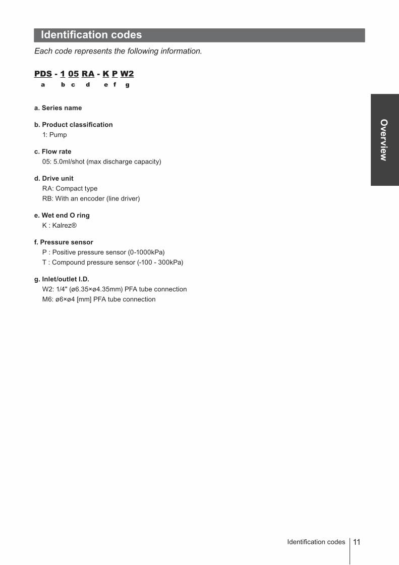
Identification codesEach code represents the following information.
PDS - 1 05 RA - K P W2 a b c d e f g
a. Series name
b. Product classification1: Pump
c. Flow rate05: 5.0ml/shot (max discharge capacity)
d. Drive unitRA: Compact typeRB: With an encoder (line driver)
e. Wet end O ringK : Kalrez®
f. Pressure sensorP : Positive pressure sensor (0-1000kPa)T : Compound pressure sensor (-100 - 300kPa)
g. Inlet/outlet I.D.W2: 1/4" (ø6.35×ø4.35mm) PFA tube connectionM6: ø6×ø4 [mm] PFA tube connection
Identification codes
12
InstallationThis section describes the installation of the pump, piping and wiring. Read through this section before work.
Points to be observedObserve the following points when installing the pump.• Be sure to turn off power to stop the pump and related devices before service is per-
formed.• Be careful for the power not to be turned on during work.• If you notice any abnormal or dangerous conditions, suspend operation immediately and
inspect/solve problems.• Do not install the pump in a flammable atmosphere.
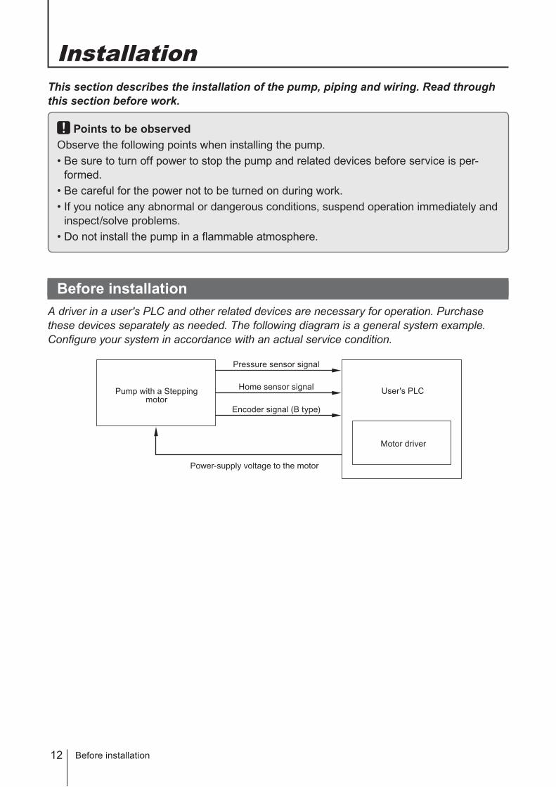
Before installationA driver in a user's PLC and other related devices are necessary for operation. Purchase these devices separately as needed. The following diagram is a general system example. Configure your system in accordance with an actual service condition.
Before installation
Pump with a Stepping motor
User's PLC
Motor driver
Home sensor signal
Power-supply voltage to the motor
Pressure sensor signal
Encoder signal (B type)
13
Installation
Installation/Piping/Wiring
Points to be observedObserve the following points during wiring work.• Electrical work should be performed by a qualified electrician. Always observe applica-
ble codes or regulations.• Do not perform wiring work while the power is on. Otherwise, an electrical shock or
short circuit may result. Be sure to turn off power before wiring work.• Be careful for the power not to be turned on during work.
NOTE Do not hold the pump head to lift the pump unit up, or the pump head may deform and a leak may result.
InstallationObserve the following points during installation.
● Installation locationMount the pump indoors. Allow sufficient space around the pump for easy access and maintenance.
● Mounting positionInstall the pump as close to a supply tank as possible in a flooded suction system.
● Mounting directionAlways direct the outlet upward. Keep the pump head in a vertical position with the check valves upright. Otherwise, performance may be reduced.
● AnchoringFix the pump with four M4 mounting screws (with PW and SW).
PipingObserve the following points during pipework.
● Pipe connectionBoth inlet and outlet of the pump have PFA tube joints. Secure every joint properly to eliminate any possibility of air ingress, or performance may be reduced.
● Fitting and tubeTake account of corrosion and pressure resistance when selecting fittings and tubes.
● Pipe resistanceKeep a piping length shortest with the minimum number of bends.
Installation/Piping/Wiring
14 Installation/Piping/Wiring
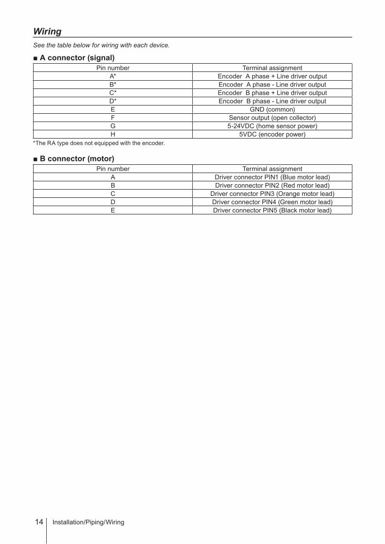
WiringSee the table below for wiring with each device.
■ A connector (signal)Pin number Terminal assignment
A* Encoder A phase + Line driver outputB* Encoder A phase - Line driver outputC* Encoder B phase + Line driver outputD* Encoder B phase - Line driver outputE GND (common)F Sensor output (open collector)G 5-24VDC (home sensor power)H 5VDC (encoder power)
*The RA type does not equipped with the encoder.
■ B connector (motor)Pin number Terminal assignment
A Driver connector PIN1 (Blue motor lead)B Driver connector PIN2 (Red motor lead)C Driver connector PIN3 (Orange motor lead)D Driver connector PIN4 (Green motor lead)E Driver connector PIN5 (Black motor lead)

15
Operation
This section describes pump operation. Observe instructions in this manu-al. See manufacturer's instruction manual for the motor driver.
Pump settingFirst, program operation of the pump.
Pulse input direction & Motor rotationThe pump lets out liquid at the input of the CCW direction command pulse and takes in liquid at the input of the CW direction command pulse.The motor-driven cylinder is at the origin at factory default setting. Before operation, use a tester to check an output of the home sensor is at the “L (GND)” level.
Number of pulses & Discharge capacity (RV)
Calculated flow rate Number of input pulses1ml 24002ml 48003ml 72004ml 96005ml 12000
* The above data is based on the assumption that the driver is set to half step with the motor-driven cylinder at the origin. Actual discharge capacity varies with a piping condition or so.
The lower limit of the motor-driven cylinder
NOTEDo not move the motor-driven cylinder over the lower limit.
Operation
Pump setting
The lower limit of sensor dog
ON position
: Suction process (CW rotation)
Home sensor
Observe the lower limit, which comes to a clock-wise rotation for 600 pulses from the ON position
Sensor dog
: Discharge process (CCW rotation)
16
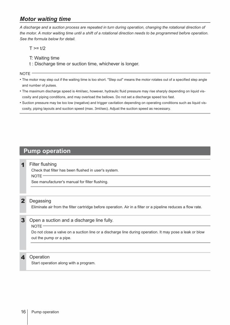
Motor waiting timeA discharge and a suction process are repeated in turn during operation, changing the rotational direction of the motor. A motor waiting time until a shift of a rotational direction needs to be programmed before operation. See the formula below for detail.
T >= t/2
T: Waiting timet : Discharge time or suction time, whichever is longer.
NOTE• The motor may step out if the waiting time is too short. "Step out" means the motor rotates out of a specified step angle
and number of pulses.
• The maximum discharge speed is 4ml/sec, however, hydraulic fluid pressure may rise sharply depending on liquid vis-
cosity and piping conditions, and may overload the bellows. Do not set a discharge speed too fast.
• Suction pressure may be too low (negative) and trigger cavitation depending on operating conditions such as liquid vis-
cosity, piping layouts and suction speed (max. 3ml/sec). Adjust the suction speed as necessary.
Pump operation
Filter flushingCheck that filter has been flushed in user's system.NOTESee manufacturer's manual for filter flushing.
DegassingEliminate air from the filter cartridge before operation. Air in a filter or a pipeline reduces a flow rate.
Open a suction and a discharge line fully.NOTEDo not close a valve on a suction line or a discharge line during operation. It may pose a leak or blow out the pump or a pipe.
OperationStart operation along with a program.
Pump operation
2
1
3
4

17
Maintenance
Troubleshooting
This section describes troubleshooting, inspection, specification and dimensions.
Points to be observedObserve the following points during maintenance work.• Follow instructions in this manual for replacement of wear parts. Do not disassemble the
pump beyond the extent of the instructions.• Always wear protective clothing such as an eye protection, chemical resistant gloves, a
mask and a face shield during disassembly, assembly or maintenance work. The spe-cific solution will dictate the degree of protection. Refer to MSDS precautions from the solution supplier.
• Solution in the discharge line may be under pressure. Release the pressure from the discharge line before disconnecting plumbing or disassembly of the pump to avoid solu-tion spray.
• Risk of electrical shock. Be sure to turn off power to stop the pump and related devices before service is performed.
TroubleshootingFirst check the following points. If the following measures do not help remove problems, con-tact your distributor.
States Possible causes SolutionsThe pump does not run.
Faulty wiring • Correct wiring and resume operation.Power-supply voltage is too low. • Observe the rated voltage of the pump.Motor failure • Check the motor. Replace as necessary.*
Liquid can not be pumped up.
Air ingress through a suction line. • Reroute piping.A failed O ring seal. • Check O rings. Replace as necessary.*Foreign matters are stuck in the flow path in the pump head or piping.
• Dismantle, inspect and clean the pump head or piping. Replace as necessary.*
Malfunction of an air-operated valve. • Check the valve. Replace as necessary.
A check valve (pump head valve) is stuck on a valve seat.
• Dismantle, inspect and clean the valve. Replace as necessary.*
A flow rate fluctuates. Foreign matters are stuck in a pipe line.
• Dismantle, inspect and clean the line. Replace as necessary.
Air stays in the pump head or in a pipe line.
• Expel air.
A check valve (pump head valve) is stuck on a valve seat.
• Dismantle, inspect and clean the valve. Replace as necessary.*
A failed O ring seal. • Check O rings. Replace as necessary.*A hydraulic fluid leak • Check for a leak. Replace as necessary.*Motor failure • Check the motor. Replace as necessary.*
Sensor signal is not outputted.
Faulty wiring • Correct wiring and resume operation.Sensor failure • Check a sensor. Replace as necessary.*
* Solutions marked with * are conducted by us.
Maintenance

18
InspectionPerform daily inspection to keep pump performance and safety.
Daily inspectionCheck for a leak or any other abnormality during operation. Upon sensing abnormality, stop operation immedi-ately and remove problems according to "Troubleshooting".
Wear part listTo run the pump for a long period, wear parts need to be replaced periodically or when pump performance has reduced. Contact your distributor for detail.
Part names Q’ty Estimated life RemarksO ring 2 Kalrez® AS568-129
Valve gasket 10 PTFEValve guide 4 PTFE
Valve 4 RUBYValve seat 4 PCTFEValve case 2 PCTFE
Inspection
19
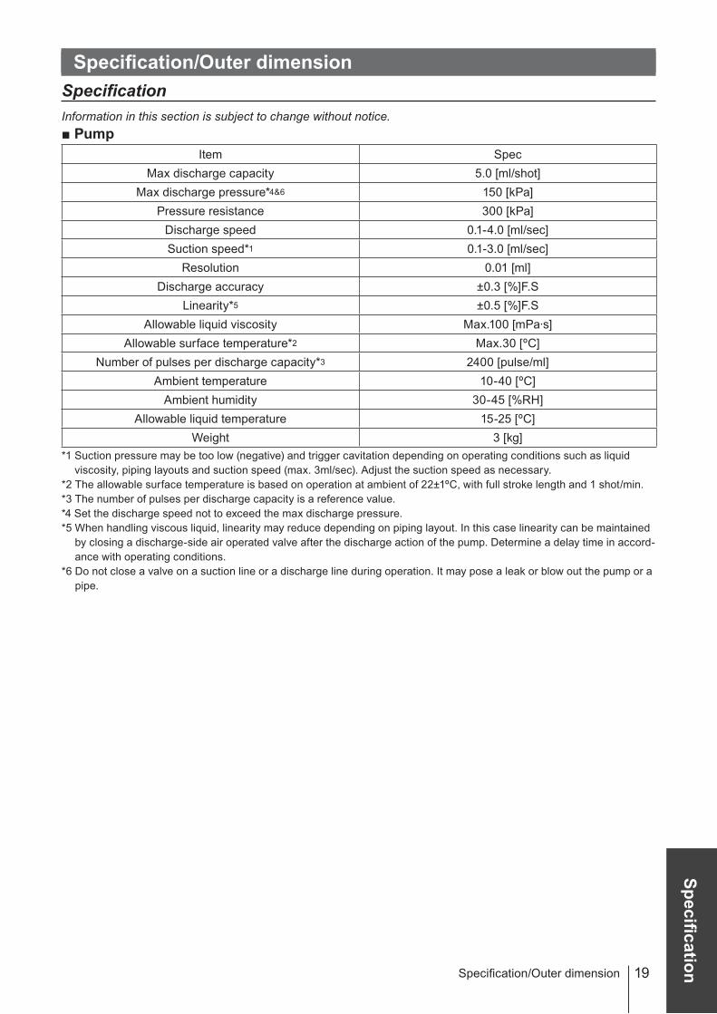
SpecificationSpecification/Outer dimension
Specification/Outer dimensionSpecificationInformation in this section is subject to change without notice.■ Pump
Item SpecMax discharge capacity 5.0 [ml/shot]
Max discharge pressure*4&6 150 [kPa]Pressure resistance 300 [kPa]
Discharge speed 0.1-4.0 [ml/sec]Suction speed*1 0.1-3.0 [ml/sec]
Resolution 0.01 [ml]Discharge accuracy ±0.3 [%]F.S
Linearity*5 ±0.5 [%]F.SAllowable liquid viscosity Max.100 [mPa·s]
Allowable surface temperature*2 Max.30 [ºC]Number of pulses per discharge capacity*3 2400 [pulse/ml]
Ambient temperature 10-40 [ºC]Ambient humidity 30-45 [%RH]
Allowable liquid temperature 15-25 [ºC]Weight 3 [kg]
*1 Suction pressure may be too low (negative) and trigger cavitation depending on operating conditions such as liquid viscosity, piping layouts and suction speed (max. 3ml/sec). Adjust the suction speed as necessary.
*2 The allowable surface temperature is based on operation at ambient of 22±1ºC, with full stroke length and 1 shot/min.*3 The number of pulses per discharge capacity is a reference value.*4 Set the discharge speed not to exceed the max discharge pressure.*5 When handling viscous liquid, linearity may reduce depending on piping layout. In this case linearity can be maintained
by closing a discharge-side air operated valve after the discharge action of the pump. Determine a delay time in accord-ance with operating conditions.
*6 Do not close a valve on a suction line or a discharge line during operation. It may pose a leak or blow out the pump or a pipe.
20 Specification/Outer dimension
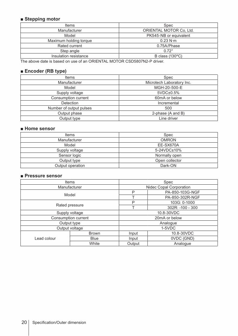
■ Stepping motorItems Spec
Manufacturer ORIENTAL MOTOR Co, Ltd. Model PK545-NB or equivalent
Maximum holding torque 0.23 N·mRated current 0.75A/Phase
Step angle 0.72°Insulation resistance B class (130ºC)
The above date is based on use of an ORIENTAL MOTOR CSD5807N2-P driver.
■ Encoder (RB type)Items Spec
Manufacturer Microtech Laboratory Inc.Model MGH-20-500-E
Supply voltage 5VDC±0.5%Consumption current 60mA or below
Detection IncrementalNumber of output pulses 500
Output phase 2-phase (A and B)Output type Line driver
■ Home sensorItems Spec
Manufacturer OMRONModel EE-SX670A
Supply voltage 5-24VDC±10%Sensor logic Normally openOutput type Open collector
Output operation Dark-ON
■ Pressure sensorItems Spec
Manufacturer Nidec Copal Corporation
Model P PA-850-103G-NGFT PA-850-302R-NGF
Rated pressure P 103G: 0-1000T 302R: -100 - 300
Supply voltage 10.8-30VDCConsumption current 20mA or below
Output type AnalogueOutput voltage 1-5VDC
Lead colourBrown Input 10.8-30VDCBlue Input 0VDC (GND)White Output Analogue

21
Specification
Outer dimension■ PDS-105R A/B
Specification/Outer dimension
IN
1/4" PFA tube
OU
T
1/4" PFA tube60
(100
)(1
82)
13.5
50(100)(189)
213.5
105
(182
)
7 161
175
44
30
44
30
(R)
(2000)
23

22 Specification/Outer dimension
Part names■ PDS-105R A/B
No. Name Q'ty Material Remarks1 Pump head unit 1 PFA2 In port unit 1 PFA3 Out port 1 PFA4 In connecting port 1 PFA5 Out connecting port 1 PFA7 O ring 2 Kalrez® AS568-12910 Valve cap 2 PP11 Valve seat 4 PCTFE12 Valve guide 4 PTFE13 Valve 4 RUBY 3/16"14 Valve gasket 10 PTFE15 Valve case 2 PCTFE16 Port support 2 SUS304
4
16
2
1
14
3
13
15
11
12
10
5
7

23
SpecificationSpecification/Outer dimension

©2011 IWAKI CO., LTD.
Thank you for choosing our product.
Please read through this instruction manual before use.
This instruction manual describes important precautions and instruc-tions for the product. Always keep it on hand for quick reference.
Instruction manual
PDS-105 RA/RB
IwakiPhotoresist Dispensing Pump
Safety instructionsO
verviewInstallation
Operation
Maintenance
( )Country codes
IWAKI CO.,LTD. 6-6 Kanda-Sudacho 2-chome Chiyoda-ku Tokyo 101-8558 JapanTEL:(81)3 3254 2935 FAX:3 3252 8892
T787 '11/09
Australia IWAKI Pumps Australia Pty. Ltd. TEL : (61)2 9899 2411 FAX : 2 9899 2421 Italy IWAKI Italia S.R.L. TEL : (39)0444 371115 FAX : 0444 335350Austria IWAKI EUROPE GmbH TEL : (49)2154 9254 0 FAX : 2154 9254 48 Korea IWAKI Korea Co.,Ltd. TEL : (82)2 2630 4800 FAX : 2 2630 4801Belgium IWAKI Belgium n.v. TEL : (32)1367 0200 FAX : 1367 2030 Malaysia IWAKIm Sdn. Bhd. TEL : (60)3 7803 8807 FAX : 3 7803 4800China IWAKI Pumps (Shanghai) Co., Ltd. TEL : (86)21 6272 7502 FAX : 21 6272 6929 Norway IWAKI Norge AS TEL : (47)23 38 49 00 FAX : 23 38 49 01China IWAKI Pumps (Guandong) Co., Ltd. TEL : (86)750 3866228 FAX : 750 3866278 Singapore IWAKI Singapore Pte. Ltd. TEL : (65)6316 2028 FAX : 6316 3221China GFTZ IWAKI Engineering & Trading (Guangzhou) TEL : (86)20 8435 0603 FAX : 20 8435 9181 Spain IWAKI Iberica Pumps, S.A. TEL : (34)943 630030 FAX : 943 628799China GFTZ IWAKI Engineering & Trading (Beijing) TEL : (86)10 6442 7713 FAX : 10 6442 7712 Sweden IWAKI Sverige AB TEL : (46)8 511 72900 FAX : 8 511 72922Denmark IWAKI Nordic A/S TEL : (45)48 24 2345 FAX : 48 24 2346 Switzerland IWAKI (Schweiz) AG TEL : (41)26 674 9300 FAX : 26 674 9302Finland IWAKI Suomi Oy TEL : (358)9 2745810 FAX : 9 2742715 Taiwan IWAKI Pumps Taiwan Co., Ltd. TEL : (886)2 8227 6900 FAX : 2 8227 6818France IWAKI France S.A. TEL : (33)1 69 63 33 70 FAX : 1 64 49 92 73 Taiwan IWAKI Pumps Taiwan (Hsin-chu) Co., Ltd. TEL : (886)3 573 5797 FAX : (886)3 573 5798Germany IWAKI EUROPE GmbH TEL : (49)2154 9254 0 FAX : 2154 9254 48 Thailand IWAKI (Thailand) Co.,Ltd. TEL : (66)2 322 2471 FAX : 2 322 2477Holland IWAKI EUROPE NL Branch TEL : (31)547 293 160 FAX : 547 292 332 U.K. IWAKI Pumps (UK) LTD. TEL : (44)1743 231363 FAX : 1743 366507Hong Kong IWAKI Pumps Co., Ltd. TEL : (852)2 607 1168 FAX : 2 607 1000 U.S.A. IWAKI AMERICA Inc. TEL : (1)508 429 1440 FAX : 508 429 1386Indonesia IWAKI Singapore (Indonesia Branch) TEL : (62)21 690 6606 FAX : 21 690 6612 Vietnam IWAKI pumps Vietnam Co.,Ltd. TEL : (84)613 933456 FAX : 613 933399
Specification