SAFETY INSTRUCTIONS AND OPERATOR S MANUAL FOR DRILLING ... Info1.pdf · SAFETY INSTRUCTIONS AND...
24
_______________________________________________________________________________________ SAFETY INSTRUCTIONS AND OPERATOR’S MANUAL FOR DRILLING MACHINE AIRBEAST 35 JEI Solutions LTD Unit 30 & 31 New Hall Hey Business Park New Hall Hey Road, Rawtenstall, Rossendale, Lancashire BB4 6HR United Kingdom Tel: 00 44 (0)1706 229490 Fax: 00 44 (0)1706 830496 E-mail: [email protected] Web: www.jeiuk.com
Transcript of SAFETY INSTRUCTIONS AND OPERATOR S MANUAL FOR DRILLING ... Info1.pdf · SAFETY INSTRUCTIONS AND...

_______________________________________________________________________________________
SAFETY INSTRUCTIONS
AND OPERATOR’S MANUAL
FOR
DRILLING MACHINE
AIRBEAST 35
JEI Solutions LTD Unit 30 & 31 New Hall Hey Business Park
New Hall Hey Road, Rawtenstall, Rossendale, Lancashire BB4 6HR United Kingdom
Tel: 00 44 (0)1706 229490 Fax: 00 44 (0)1706 830496 E-mail: [email protected] Web: www.jeiuk.com
2
INDEX
1. INTENDED USE ............................................................................................................................. 3
2. TECHNICAL DATA ......................................................................................................................... 4
3. STANDARD ACCESSORIES ......................................................................................................... 5
4. SAFE WORKING CONDITIONS .................................................................................................... 5
5. BEFORE STARTING WORK .......................................................................................................... 7
6. MAINTENANCE AND SERVICING .............................................................................................. 10
7. PARTS LIST .................................................................................................................................. 12
8. DECLARATION OF CONFORMITY ............................................................................................. 22
9. QUALITY CERTIFICATE .............................................................................................................. 23
10. GUARANTEE CERTIFICATE ....................................................................................................... 24

3
1. INTENDED USE
Thanks to its properties and capabilities concerning the dimensions of drilled
openings, this drill is perfect for use on any construction site and industrial installations
where electric appliances are prohibited for safety reasons, and the dimensions and
character of the elements involved make it impossible for them to be transported to
another location.
Using the drill Airforce 35 AD-A with magnetic base and special milling cutters gives
the ability to make holes with diameters up to 35 mm and a depth of 25 mm with a
precision only previously found in a workshop.
The magnetic base of the drill ensures the attachment of the machine to steel
constructions, with enough force to guarantee the correct functioning of the appliance as
well as the user’s safety. This method of affixing the machine makes it possible to make
holes in many different positions, for example, on vertical pillars or steel ceilings. In these
cases, despite the considerable force of the magnet, all drills must be secured using safety
belts or chains included with the equipment. This action eliminates potential risk in the
case of a pressure drop in the net.
The compressed-air motor used in the Airforce 35 AD-A drill is certified ATEX
II2 G/D C IIC T6;T4 and meets the requirements for use in areas with a risk of
explosion.

4
2. TECHNICAL DATA
Operating pressure 6 bar
Air consumption (1400 l/min) 369.84 gal/min
(218.72 yd/min)
Motor power 800 W
Arbor size 3/4” Weldon /19,05 mm/
Hole capacity with annular cutter 35mm (1.38 in)
Maximum drilling depth 25mm (0.98 in)
Stroke 39mm (1.54 in)
Magnet force [25mm, Ra=1,25] 6,500 N
Free speed 500 rpm
Load speed 240 rpm
Magnetic base 80x80x143 mm
Weight 14kg (30.86 lb)
Noise level up to 70 dB
Working temperature range -20C /+ 40C
183
133
188460
292

5
3. STANDARD ACCESSORIES
The product includes
- metal box qt. 1
- drill qt. 1
- allen key SW4 qt. 1
- allen key SW3 qt. 1
- cooling system qt. 1
- handle assembly qt. 1
- pilot pin qt. 1
- safety chain qt. 1
- instruction manual qt. 1
4. SAFE WORKING CONDITIONS
The drill should never be used when:
1. The operator has not become familiar with the user’s manual and has not been trained
in industrial safety.
2. The machine is to be used for purposes that are not appropriate as stated in the user’s
manual.
3. The drill is not complete or parts used in its repair are not original.
4. The air parameters are not consistent with those given on the rating plate.
5. The operator has not checked the state of the machine before beginning its operation,
especially the state of the air line, positions of levers and cutting tools.
6. The machine is not secured with a chain, especially during operation at a height and in
inverted positions.
7. Outside persons are found in the immediate vicinity of the work area.
6
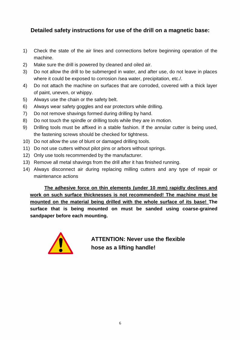
Detailed safety instructions for use of the drill on a magnetic base:
1) Check the state of the air lines and connections before beginning operation of the
machine.
2) Make sure the drill is powered by cleaned and oiled air.
3) Do not allow the drill to be submerged in water, and after use, do not leave in places
where it could be exposed to corrosion /sea water, precipitation, etc./.
4) Do not attach the machine on surfaces that are corroded, covered with a thick layer
of paint, uneven, or whippy.
5) Always use the chain or the safety belt.
6) Always wear safety goggles and ear protectors while drilling.
7) Do not remove shavings formed during drilling by hand.
8) Do not touch the spindle or drilling tools while they are in motion.
9) Drilling tools must be affixed in a stable fashion. If the annular cutter is being used,
the fastening screws should be checked for tightness.
10) Do not allow the use of blunt or damaged drilling tools.
11) Do not use cutters without pilot pins or arbors without springs.
12) Only use tools recommended by the manufacturer.
13) Remove all metal shavings from the drill after it has finished running.
14) Always disconnect air during replacing milling cutters and any type of repair or
maintenance actions
The adhesive force on thin elements (under 10 mm) rapidly declines and
work on such surface thicknesses is not recommended! The machine must be
mounted on the material being drilled with the whole surface of its base! The
surface that is being mounted on must be sanded using coarse-grained
sandpaper before each mounting.
ATTENTION: Never use the flexible
hose as a lifting handle!

7
5. BEFORE STARTING WORK
5.1 Operation of the annular cutter.
The drill’s spindle has a socket with a Weldon 19,05 mm shank.
An annular cutter (1) secured by screws (3) is mounted in the spindle (2). Pay
attention to correctly screwing in the fastening screws while mounting the milling cutter on
the fixture, so that they won’t unscrew themselves during the operation of the machine. It
is important to situate the milling cutter relative to the fixture’s body, so that the fastening
planes on the milling fixture are located opposite to the fastening screws (3). Whatever the
clamping, both fastening screws (3) must be used.
A pilot pin (5) is located inside the milling cutter. This aligning pin facilitates the
correct positioning of the drilling axis. As the milling cutter sinks into the material during the
drilling, the pilot pin draws back to the inside of the fixture, stretching the spring (4). The
spring causes the core formed during the drilling to be pushed out once the milling cutter
cuts through the entire thickness of the material.
Fig. 2
Operation of the annular cutters
Fig. 3
Holes that are possible to make using the annular cutter

8
Basically milling cutters are designed to make through holes. The only exception to
using the pilot pin is when performing blind holes.
5.2 Operate
The drill is provided to the client in a metal box along with the complete standard
equipment. Verify that the parts in the packaging correspond with the specifications found
in this user’s manual – see point 3. Steel elements coated with a layer of lubricant for the
period of storage and transport must be cleaned prior to their usage.
The magnet (MAGNET) switch and the motor connection lever (MOTOR) are part of
the control elements. The location of these elements is shown on fig.4.
In order to start the machine:
- turn the magnet switch to the ON position. Prior to this, make sure that the motor
connection lever is in the OFF position.
- turn the motor connection lever to the ON position.
- turning the motor connection lever to the OFF position will cause the motor to stop
running. The magnetic base will still be on.
- in order to change the drilling location, the magnet switch should be set to the OFF
position after the drive has been stopped.
ATTENTION: REA
Fig. 4
Drill control elements
ON MAGNET OFF
OFF
ON
MOTOR
9
D USAGE INSTRUCTIONS –
READ CAREFULLY BEFORE USING THIS APPLIANCE
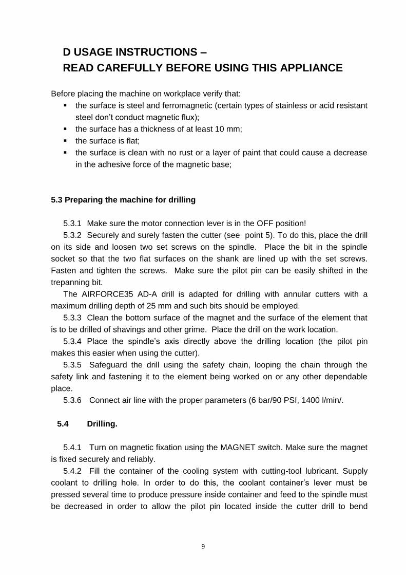
Before placing the machine on workplace verify that:
the surface is steel and ferromagnetic (certain types of stainless or acid resistant
steel don’t conduct magnetic flux);
the surface has a thickness of at least 10 mm;
the surface is flat;
the surface is clean with no rust or a layer of paint that could cause a decrease
in the adhesive force of the magnetic base;
5.3 Preparing the machine for drilling
5.3.1 Make sure the motor connection lever is in the OFF position!
5.3.2 Securely and surely fasten the cutter (see point 5). To do this, place the drill
on its side and loosen two set screws on the spindle. Place the bit in the spindle
socket so that the two flat surfaces on the shank are lined up with the set screws.
Fasten and tighten the screws. Make sure the pilot pin can be easily shifted in the
trepanning bit.
The AIRFORCE35 AD-A drill is adapted for drilling with annular cutters with a
maximum drilling depth of 25 mm and such bits should be employed.
5.3.3 Clean the bottom surface of the magnet and the surface of the element that
is to be drilled of shavings and other grime. Place the drill on the work location.
5.3.4 Place the spindle’s axis directly above the drilling location (the pilot pin
makes this easier when using the cutter).
5.3.5 Safeguard the drill using the safety chain, looping the chain through the
safety link and fastening it to the element being worked on or any other dependable
place.
5.3.6 Connect air line with the proper parameters (6 bar/90 PSI, 1400 l/min/.
5.4 Drilling.
5.4.1 Turn on magnetic fixation using the MAGNET switch. Make sure the magnet
is fixed securely and reliably.
5.4.2 Fill the container of the cooling system with cutting-tool lubricant. Supply
coolant to drilling hole. In order to do this, the coolant container’s lever must be
pressed several time to produce pressure inside container and feed to the spindle must
be decreased in order to allow the pilot pin located inside the cutter drill to bend
10
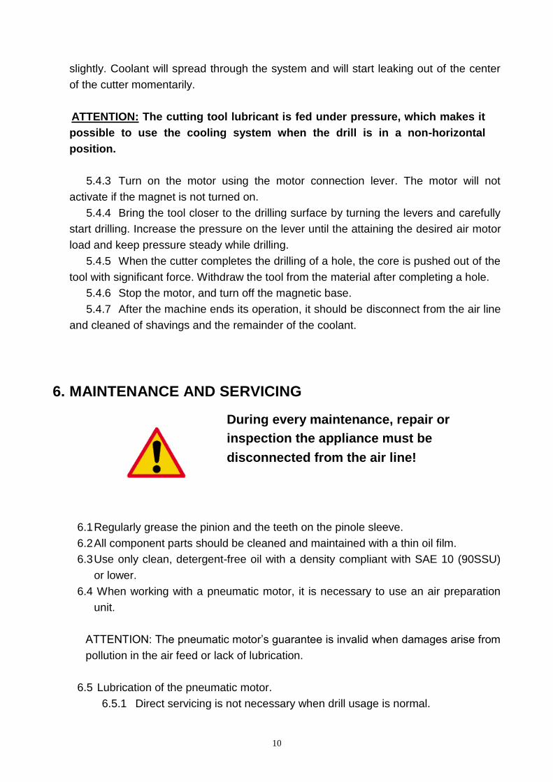
slightly. Coolant will spread through the system and will start leaking out of the center
of the cutter momentarily.
ATTENTION: The cutting tool lubricant is fed under pressure, which makes it
possible to use the cooling system when the drill is in a non-horizontal
position.
5.4.3 Turn on the motor using the motor connection lever. The motor will not
activate if the magnet is not turned on.
5.4.4 Bring the tool closer to the drilling surface by turning the levers and carefully
start drilling. Increase the pressure on the lever until the attaining the desired air motor
load and keep pressure steady while drilling.
5.4.5 When the cutter completes the drilling of a hole, the core is pushed out of the
tool with significant force. Withdraw the tool from the material after completing a hole.
5.4.6 Stop the motor, and turn off the magnetic base.
5.4.7 After the machine ends its operation, it should be disconnect from the air line
and cleaned of shavings and the remainder of the coolant.
6. MAINTENANCE AND SERVICING
6.1 Regularly grease the pinion and the teeth on the pinole sleeve.
6.2 All component parts should be cleaned and maintained with a thin oil film.
6.3 Use only clean, detergent-free oil with a density compliant with SAE 10 (90SSU)
or lower.
6.4 When working with a pneumatic motor, it is necessary to use an air preparation
unit.
ATTENTION: The pneumatic motor’s guarantee is invalid when damages arise from
pollution in the air feed or lack of lubrication.
6.5 Lubrication of the pneumatic motor.
6.5.1 Direct servicing is not necessary when drill usage is normal.
During every maintenance, repair or
inspection the appliance must be
disconnected from the air line!

11
6.5.2 It is necessary to use an air preparation unit in the air feed system.
6.5.3 Inspections and servicing of the air preparation unit should be carried out
as needed depending on the air pollution level. Clean the filter, dry out the
dehydrator, and maintain an oil level with drips every 2-5 seconds.
6.5.4 Oil used in the air preparation unit must have an ignition temperature
higher than 260°C.
6.6 Any type of mechanical repair of the drill should be done at a service
workshop recommended by the vendor. When repairing use only original parts.
ATTENTION: The AIRFORCE35 AD-A drill is adapted for powered by air with
working pressure 4 to 6 bar /60 to 90 PSI/. Maintenance of the machine's technical
parameters and its general state are strictly dependent on the cleanness and
preparation of the air and proper servicing.
12
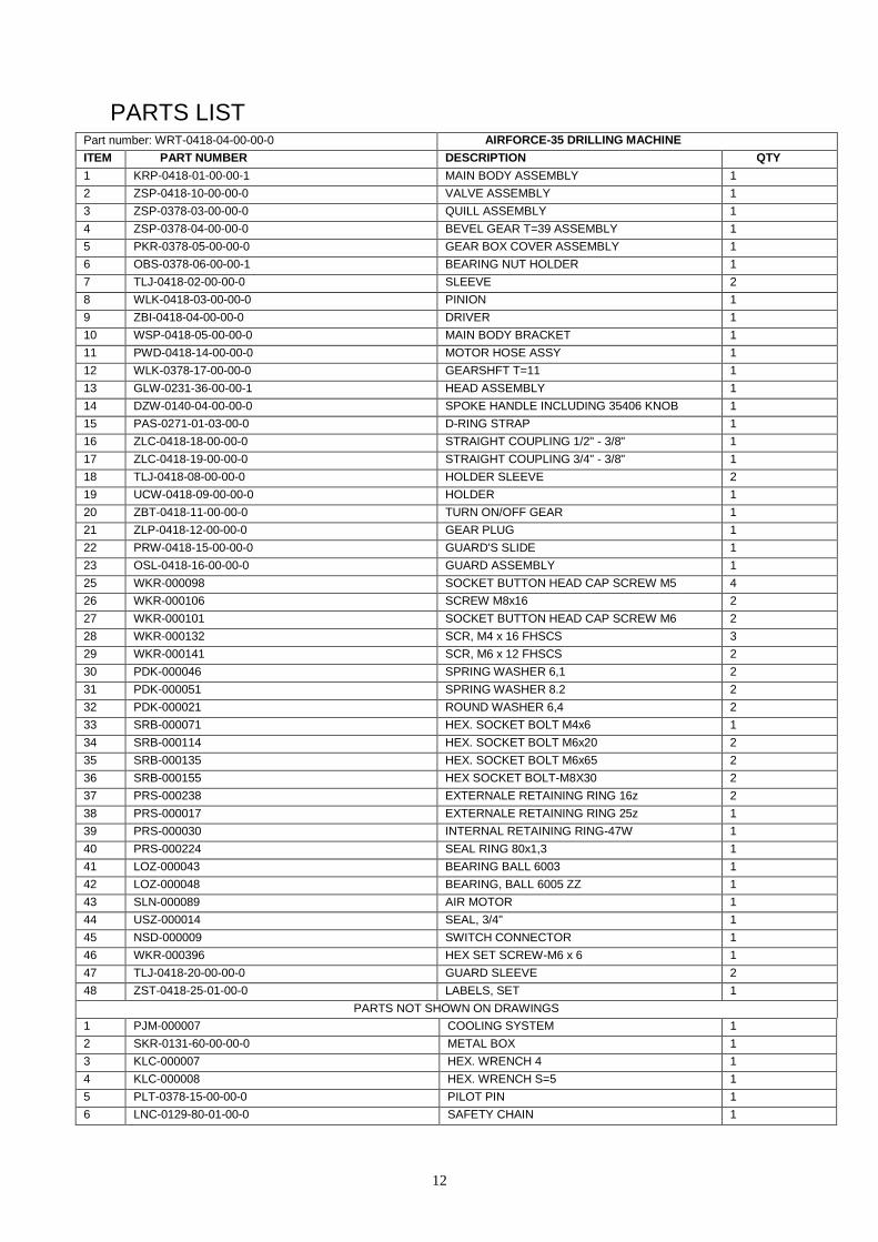
PARTS LIST Part number: WRT-0418-04-00-00-0 AIRFORCE-35 DRILLING MACHINE
ITEM PART NUMBER DESCRIPTION QTY
1 KRP-0418-01-00-00-1 MAIN BODY ASSEMBLY 1
2 ZSP-0418-10-00-00-0 VALVE ASSEMBLY 1
3 ZSP-0378-03-00-00-0 QUILL ASSEMBLY 1
4 ZSP-0378-04-00-00-0 BEVEL GEAR T=39 ASSEMBLY 1
5 PKR-0378-05-00-00-0 GEAR BOX COVER ASSEMBLY 1
6 OBS-0378-06-00-00-1 BEARING NUT HOLDER 1
7 TLJ-0418-02-00-00-0 SLEEVE 2
8 WLK-0418-03-00-00-0 PINION 1
9 ZBI-0418-04-00-00-0 DRIVER 1
10 WSP-0418-05-00-00-0 MAIN BODY BRACKET 1
11 PWD-0418-14-00-00-0 MOTOR HOSE ASSY 1
12 WLK-0378-17-00-00-0 GEARSHFT T=11 1
13 GLW-0231-36-00-00-1 HEAD ASSEMBLY 1
14 DZW-0140-04-00-00-0 SPOKE HANDLE INCLUDING 35406 KNOB 1
15 PAS-0271-01-03-00-0 D-RING STRAP 1
16 ZLC-0418-18-00-00-0 STRAIGHT COUPLING 1/2" - 3/8" 1
17 ZLC-0418-19-00-00-0 STRAIGHT COUPLING 3/4" - 3/8" 1
18 TLJ-0418-08-00-00-0 HOLDER SLEEVE 2
19 UCW-0418-09-00-00-0 HOLDER 1
20 ZBT-0418-11-00-00-0 TURN ON/OFF GEAR 1
21 ZLP-0418-12-00-00-0 GEAR PLUG 1
22 PRW-0418-15-00-00-0 GUARD'S SLIDE 1
23 OSL-0418-16-00-00-0 GUARD ASSEMBLY 1
25 WKR-000098 SOCKET BUTTON HEAD CAP SCREW M5 4
26 WKR-000106 SCREW M8x16 2
27 WKR-000101 SOCKET BUTTON HEAD CAP SCREW M6 2
28 WKR-000132 SCR, M4 x 16 FHSCS 3
29 WKR-000141 SCR, M6 x 12 FHSCS 2
30 PDK-000046 SPRING WASHER 6,1 2
31 PDK-000051 SPRING WASHER 8.2 2
32 PDK-000021 ROUND WASHER 6,4 2
33 SRB-000071 HEX. SOCKET BOLT M4x6 1
34 SRB-000114 HEX. SOCKET BOLT M6x20 2
35 SRB-000135 HEX. SOCKET BOLT M6x65 2
36 SRB-000155 HEX SOCKET BOLT-M8X30 2
37 PRS-000238 EXTERNALE RETAINING RING 16z 2
38 PRS-000017 EXTERNALE RETAINING RING 25z 1
39 PRS-000030 INTERNAL RETAINING RING-47W 1
40 PRS-000224 SEAL RING 80x1,3 1
41 LOZ-000043 BEARING BALL 6003 1
42 LOZ-000048 BEARING, BALL 6005 ZZ 1
43 SLN-000089 AIR MOTOR 1
44 USZ-000014 SEAL, 3/4" 1
45 NSD-000009 SWITCH CONNECTOR 1
46 WKR-000396 HEX SET SCREW-M6 x 6 1
47 TLJ-0418-20-00-00-0 GUARD SLEEVE 2
48 ZST-0418-25-01-00-0 LABELS, SET 1
PARTS NOT SHOWN ON DRAWINGS
1 PJM-000007 COOLING SYSTEM 1
2 SKR-0131-60-00-00-0 METAL BOX 1
3 KLC-000007 HEX. WRENCH 4 1
4 KLC-000008 HEX. WRENCH S=5 1
5 PLT-0378-15-00-00-0 PILOT PIN 1
6 LNC-0129-80-01-00-0 SAFETY CHAIN 1

_______________________________________________________________________________________

14
Part Number:KRP-0378-01-00-00-0 MAIN BODY ASSEMBLY
ITEM PART NUMBER DESCRIPTION QTY
1.1 KRP-0418-01-01-00-2 MAIN BODY 1
1.2 TLJ-0378-01-05-00-0 BUSHING PERMAGLIDE 1
1.3 WKR-000031 HEX. INSERT SCREW M8x6 1
1.4 PLY-0418-01-02-00-0 MAIN BODY PLATE 1
1.5 WKR-000130 SCR, M4 x 10 FHSCS 2
_______________________________________________________________________________________
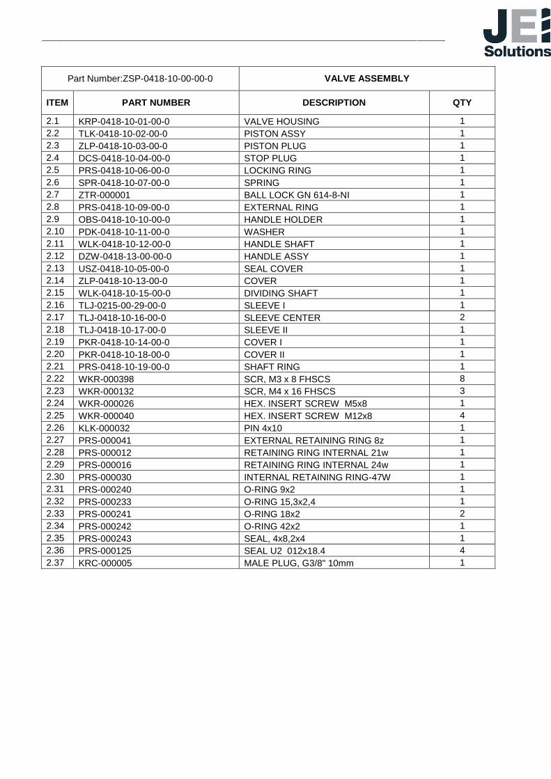
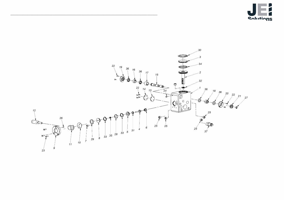
Part Number:ZSP-0418-10-00-00-0 VALVE ASSEMBLY
ITEM PART NUMBER DESCRIPTION QTY
2.1 KRP-0418-10-01-00-0 VALVE HOUSING 1
2.2 TLK-0418-10-02-00-0 PISTON ASSY 1
2.3 ZLP-0418-10-03-00-0 PISTON PLUG 1
2.4 DCS-0418-10-04-00-0 STOP PLUG 1
2.5 PRS-0418-10-06-00-0 LOCKING RING 1
2.6 SPR-0418-10-07-00-0 SPRING 1
2.7 ZTR-000001 BALL LOCK GN 614-8-NI 1
2.8 PRS-0418-10-09-00-0 EXTERNAL RING 1
2.9 OBS-0418-10-10-00-0 HANDLE HOLDER 1
2.10 PDK-0418-10-11-00-0 WASHER 1
2.11 WLK-0418-10-12-00-0 HANDLE SHAFT 1
2.12 DZW-0418-13-00-00-0 HANDLE ASSY 1
2.13 USZ-0418-10-05-00-0 SEAL COVER 1
2.14 ZLP-0418-10-13-00-0 COVER 1
2.15 WLK-0418-10-15-00-0 DIVIDING SHAFT 1
2.16 TLJ-0215-00-29-00-0 SLEEVE I 1
2.17 TLJ-0418-10-16-00-0 SLEEVE CENTER 2
2.18 TLJ-0418-10-17-00-0 SLEEVE II 1
2.19 PKR-0418-10-14-00-0 COVER I 1
2.20 PKR-0418-10-18-00-0 COVER II 1
2.21 PRS-0418-10-19-00-0 SHAFT RING 1
2.22 WKR-000398 SCR, M3 x 8 FHSCS 8
2.23 WKR-000132 SCR, M4 x 16 FHSCS 3
2.24 WKR-000026 HEX. INSERT SCREW M5x8 1
2.25 WKR-000040 HEX. INSERT SCREW M12x8 4
2.26 KLK-000032 PIN 4x10 1
2.27 PRS-000041 EXTERNAL RETAINING RING 8z 1
2.28 PRS-000012 RETAINING RING INTERNAL 21w 1
2.29 PRS-000016 RETAINING RING INTERNAL 24w 1
2.30 PRS-000030 INTERNAL RETAINING RING-47W 1
2.31 PRS-000240 O-RING 9x2 1
2.32 PRS-000233 O-RING 15,3x2,4 1
2.33 PRS-000241 O-RING 18x2 2
2.34 PRS-000242 O-RING 42x2 1
2.35 PRS-000243 SEAL, 4x8,2x4 1
2.36 PRS-000125 SEAL U2 012x18.4 4
2.37 KRC-000005 MALE PLUG, G3/8" 10mm 1
_______________________________________________________________________________________

17
Part Number:TLK-0418-10-02-00-0 PISTON ASSY
ITEM PART NUMBER DESCRIPTION QTY
2.2.1 TLK-0418-10-02-01-0 PISTON 1
2.2.2 LST-0418-10-02-02-0 PISTON GEAR RACK 1
2.2.3 PRS-000194 O-RING 39,2x3 1
18
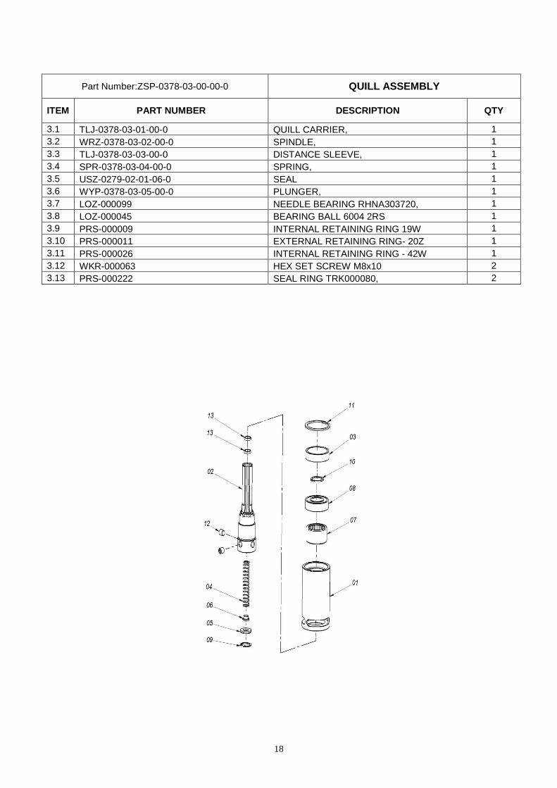
Part Number:ZSP-0378-03-00-00-0 QUILL ASSEMBLY
ITEM PART NUMBER DESCRIPTION QTY
3.1 TLJ-0378-03-01-00-0 QUILL CARRIER, 1
3.2 WRZ-0378-03-02-00-0 SPINDLE, 1
3.3 TLJ-0378-03-03-00-0 DISTANCE SLEEVE, 1
3.4 SPR-0378-03-04-00-0 SPRING, 1
3.5 USZ-0279-02-01-06-0 SEAL 1
3.6 WYP-0378-03-05-00-0 PLUNGER, 1
3.7 LOZ-000099 NEEDLE BEARING RHNA303720, 1
3.8 LOZ-000045 BEARING BALL 6004 2RS 1
3.9 PRS-000009 INTERNAL RETAINING RING 19W 1
3.10 PRS-000011 EXTERNAL RETAINING RING- 20Z 1
3.11 PRS-000026 INTERNAL RETAINING RING - 42W 1
3.12 WKR-000063 HEX SET SCREW M8x10 2
3.13 PRS-000222 SEAL RING TRK000080, 2

19
Part Number:ZSP-0378-04-00-00-0 BEVEL GEAR T=39 ASSEMBLY
ITEM PART NUMBER DESCRIPTION QTY
4.1 KOL-0378-04-01-00-0 BEVEL GEAR T=39 ASSY / INCL. SLEEVE 1
4.2 TLJ-0378-04-02-00-0 BEARING NUT 1
4.3 LOZ-000089 BEARING BALL 61805 2RS 1
4.4 PRS-000223 EXTERNAL RETAINING RING 25Z TYPE A 1
4.5 PRS-000025 INTERNAL RETAINING RING 37W 1
4.6 WKR-000043 HEX SET SCREW M5x10 1

20
Part Number:KOL-0378-04-01-00-0 BEVEL GEAR T=39 ASSY / INCL. SLEEVE
ITEM PART NUMBER DESCRIPTION QTY
4.1.1 TLJ-0378-04-01-01-0 SLEEVE 1
4.1.2 KOL-0378-04-01-02-0 BEVEL GEAR T=39 1
4.1.3 LOZ-000100 BEARING BALL 6806 LLU 1
4.1.4 PRS-000021 EXTERNAL RETAINING RING 30z 1

21
Part Number:PKR-0378-05-00-00-0 GEAR BOX COVER ASSEMBLY
ITEM PART NUMBER DESCRIPTION QTY
5.1 PKR-0378-05-01-00-0 GEAR BOX COVER 1
5.2 RRA-0378-05-02-00-0 JUMPER 1
5.3 KNC-0234-00-10-00-0 COOLING TIP 1

22
7. DECLARATION OF CONFORMITY
PROMOTECH Sp. z o.o.
str. Elewatorska 23/1
15-620 Białystok, Polska
Declaration of Conformity
We declare, with full liability, that the product:
Pneumatically driven drill AIRFORCE35 AD-A with magnetic
base
to which this declaration refers to conforms to the following Directive: 2006/42/WE.
Białystok 08.10.2009
Chairman of the Company Board

23
8. QUALITY CERTIFICATE
MACHINE INSPECTION CARD
Pneumatically driven drill AIRFORCE35 AD-A with magnetic base
Serial number ________________
Spindle lateral whip ________________
Perpendicularity of spindle motion relative to base ________________
Perpendicularity of spindle axis relative to base ________________
Base adhesive strength ________________ (surface with a min. thickness of 22 mm and smoothness less than 1.25)
Machine examined by ____________________
Quality Control:. ____________________

24
9. GUARANTEE CERTIFICATE
1. The manufacturer offers the buyer a 6 month guarantee from the date of purchase, but not longer
than 12 months from the date of production, on the stand and the power feed installed on the stand during its manufacture and being a machine as a whole with the stand.
2. The buyer voids the guarantee or warranty in the event of: - removal of the guarantee seals; - unauthorized repairs or modification; - usage of the machine for purposes not specified in the user’s manual; - usage of inappropriate tools or other materials not specified in the user’s manual; the occurrence of damages caused by reasons other than flaws of the materials or improper installation. 3. The guarantor is obligated to carry out repairs concerning the guarantee within 14 days of
the delivery of the machine to the point of service. This time is increased to 21 days if the machine is sent by mail. In the event of damage to the power feed, time for repair is increased to 30 days.
4. The guarantee or warranty does not include: safety fuses, cutting tools, the machine’s standard equipment, power feed brushes, or damage arising from the normal wear of the machine (for example scratches on the adhesive side of the base).
5. Machines not packed in their original packaging will not be accepted for repairs concerning the guarantee, and after the period, the vendor does not take responsibility for any damage to the machine arising from shipping to and from the service point if the machine is not packed in the original packaging.
Date of Production.. Factory No. : …....................................................
Quality Control:.
Date of sale:..
Vendor Signature and Stamp