Safety Instruction Diagnostic Faceplate - Home - D&D ... posts/Rockwell's... · In Factory Talk...
7
Safety Instruction Diagnostic Faceplate Adding a safety Instruction faceplate to existing safety program with Control Logix and Panel View Studio Download the content from the AB website and place it in a folder named “Resources” Open Control Logix program and panel view application that you want to edit. In Control Logix Import “SafetyInsructtion_FaceplateAnimation_UDT.L5X” from the resources folder.
Transcript of Safety Instruction Diagnostic Faceplate - Home - D&D ... posts/Rockwell's... · In Factory Talk...

Safety Instruction Diagnostic Faceplate
Adding a safety Instruction faceplate to existing safety program with Control Logix
and Panel View Studio
Download the content from the AB website and place it in a folder named
“Resources”
Open Control Logix program and panel view application that you want to edit.
In Control Logix Import “SafetyInsructtion_FaceplateAnimation_UDT.L5X” from the
resources folder.
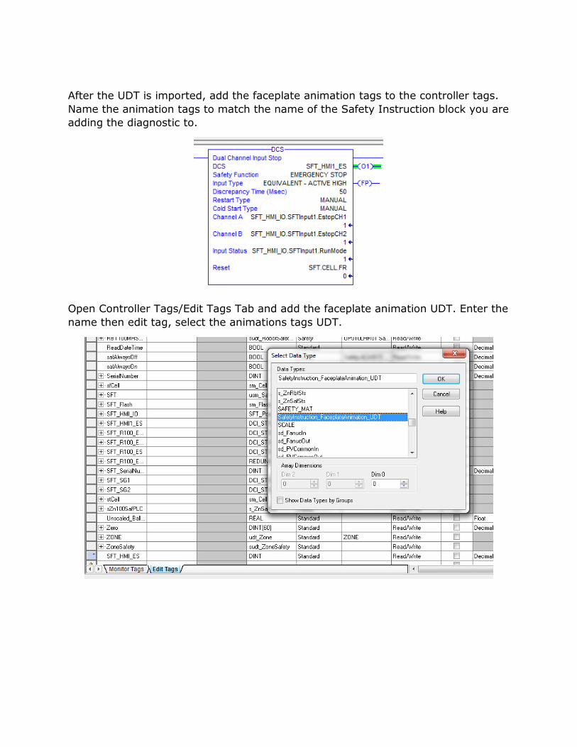
After the UDT is imported, add the faceplate animation tags to the controller tags.
Name the animation tags to match the name of the Safety Instruction block you are
adding the diagnostic to.
Open Controller Tags/Edit Tags Tab and add the faceplate animation UDT. Enter the
name then edit tag, select the animations tags UDT.

In Factory Talk View Studio import the safety instruction faceplate and the GoTo
Safety instruction graphic from the resource folder.
Repeat for the GoTo safety instruction graphic.
Import all of the safety instruction images from the resource folder.

Import the safety instruction parameter file from the resource folder.
Open the safety instruction faceplate from the graphics area. Right click the Safety
Instruction faceplate. Select Tag substitution.
Search and replace the #1 with the tag pointing to the Safety Instruction you are
intending to monitor.**DO NOT FORGET TO REMOVE BRACKETS**

Search and replace the #2 with the tag pointing to the “Faceplate Animation Tag”
of the UDT tag that was created In the Logix program.
**DO NOT FORGET TO REMOVE BRACKETS**
Open the GoTo Safety Instruction Graphic and copy Instruction_1 and paste it to
the desired screen. Instruction_1 has more detailed diagnostic functions than
Instruction_2.
Search and replace the “[GLX-L62S]InstructionName_1” with the tag pointing to
the Safety Instruction you are intending to monitor.

Right click the bottom graphic in the GoTo instruction and select properties. Under
the label tab, change the image to the type of safety device you intend to monitor.
Right click the Top text box in the GoTo instruction and select properties. Under the
States tab, change the states text to the name of safety device you intend to
monitor.

Testing
Create a runtime file to test
Press the E-Stop object to open the diagnostic window
To rename the faceplate, click in the title bar, type the new name by using the
popup Keyboard, and press Enter.
In Control Logix or on the physical safety device you can force the safety instruction to
fault (eg. jumpering the channels together, removing one channel while the other in still
energized…).
The faceplate includes these buttons:
• The Fault button launches the fault Probable Cause and Recommended Actions
views.
• The Diagnostics button launches the diagnostic Probable Cause and
Recommended Actions views.