SAFETY INFORMATION - ContinuousWavecontinuouswave.com/whaler/reference/BRP/ICommand... · The...
40
Transcript of SAFETY INFORMATION - ContinuousWavecontinuouswave.com/whaler/reference/BRP/ICommand... · The...


SAFETY INFORMATIONThis booklet is written for qualified, factory-trainedtechnicians who are already familiar with the useof Evinrude®/Johnson® Special Tools. This bookletis not a substitute for work experience. It is anorganized guide for installation of the I-Commandsystem.
This booklet uses the following signal words iden-tifying important safety messages.
IMPORTANT: Identifies information that will helpprevent damage to machinery and appears nextto information that controls correct assembly andoperation of the product.
These safety alert signal words mean:ATTENTION!BECOME ALERT!YOUR SAFETY IS INVOLVED!
Always follow common shop safety practices. Ifyou have not had training related to common shopsafety practices, you should do so to protect your-self, as well as the people around you.
It is understood that this booklet may be trans-lated into other languages. In the event of any dis-crepancy, the English version shall prevail.
DO NOT perform any installation until you haveread the instructions and checked the picturesrelating to the installation procedures.
Be careful, and never rush or guess a service pro-cedure. Human error is caused by many factors:carelessness, fatigue, overload, preoccupation,unfamiliarity with the product, and drugs and alco-hol use, to name a few. Damage to a boat andoutboard can be fixed in a short period of time, butinjury or death has a lasting effect.
When replacement parts are required, useEvinrude/Johnson Genuine Parts or parts withequivalent characteristics, including type, strengthand material. Using substandard parts could resultin injury or product malfunction.
Torque wrench tightening specifications must bestrictly followed. Replace any locking fastener(locknut or patch screw) if its locking featurebecomes weak. Definite resistance to turningmust be felt when reusing a locking fastener. Ifreplacement is specified or required because thelocking fastener has become weak, use onlyauthorized Evinrude/Johnson Genuine Parts.
If you use procedures or service tools that are notrecommended in this instruction booklet, YOUALONE must decide if your actions might injurepeople or damage the outboard.
DANGERIndicates an imminently hazardous situationwhich, if not avoided, WILL result in deathor serious injury.
WARNINGIndicates a potentially hazardous situationwhich, if not avoided, CAN result in severeinjury or death.
CAUTIONIndicates a potentially hazardous situationwhich, if not avoided, MAY result in minor ormoderate personal injury or property dam-age. It also may be used to alert againstunsafe practices.
The following trademarks are the property of Bombardier Recreational Products Inc. or its affiliates.Evinrude ® I-Command ™
Evinrude ® E-TEC ® Johnson ®
† NMEA 2000 is a registered trademark of the National Marine Electronics Association or its subsidiaries.† DeviceNet is a registered trademark ODVA† Deutsch is a registered trademark of The Deutsch Company© 2009 BRP US Inc. All rights reserved.TM, ® Trademarks and registered trademarks of Bombardier Recreational Products Inc. or its affiliates.

Before working on any part of the outboard, read the following SAFETY information.
DANGERContact with a rotating propeller is likely to result in serious injury or death. Assure theengine and prop area is clear of people and objects before starting engine or operating boat.Do not allow anyone near a propeller, even when the engine is off. Blades can be sharp andthe propeller can continue to turn even after the engine is off. Remove propeller before ser-vicing and when running the outboard on a flushing device.
DO NOT run the engine indoors or without adequate ventilation or permit exhaust fumes toaccumulate in confined areas. Engine exhaust contains carbon monoxide which, if inhaled,can cause serious brain damage or death.
WARNINGWear safety glasses to avoid personal injury, and set compressed air to less than 25 psi (172kPa).The motor cover and flywheel cover are machinery guards. Use caution when conductingtests on running outboards. DO NOT wear jewelry or loose clothing. Keep hair, hands, andclothing away from rotating parts.During service, the outboard may drop unexpectedly. Avoid personal injury; always supportthe outboard’s weight with a suitable hoist or the tilt support bracket during service.To prevent accidental starting while servicing, disconnect the battery cables at the battery.Twist and remove all spark plug leads.The electrical system presents a serious shock hazard. DO NOT handle primary or secondaryignition components while outboard is running or flywheel is turning.Gasoline is extremely flammable and highly explosive under certain conditions. Use cautionwhen working on any part of the fuel system.Protect against hazardous fuel spray. Before starting any fuel system service, carefullyrelieve fuel system pressure.Do not smoke, or allow open flames or sparks, or use electrical devices such as cellularphones in the vicinity of a fuel leak or while fueling.Keep all electrical connections clean, tight, and insulated to prevent shorting or arcing andcausing an explosion.Always work in a well ventilated area.Replace any locking fastener (locknut or patch screw) if its locking feature becomes weak.Definite resistance to tightening must be felt when reusing a locking fastener. If replacementis indicated, use only authorized replacement or equivalent.
2

TABLE OF CONTENTS
TABLE OF CONTENTSI-COMMAND SYSTEM
DESCRIPTION . . . . . . . . . . . . . . . . . . . . . . . . . . . . . . . . . . . . . . . . . . . . . . . . . . . . . . . . . . . . . . . . . . . . . . 5I-COMMAND “DIGITAL” SERIES FEATURES . . . . . . . . . . . . . . . . . . . . . . . . . . . . . . . . . . . . . . . . . . . . . 6I-Command “Digital” Displays . . . . . . . . . . . . . . . . . . . . . . . . . . . . . . . . . . . . . . . . . . . . . . . . . . . . . . . . . 7NETWORK SPECIFICATIONS . . . . . . . . . . . . . . . . . . . . . . . . . . . . . . . . . . . . . . . . . . . . . . . . . . . . . . . . . 8
NMEA 2000 Network Diagram . . . . . . . . . . . . . . . . . . . . . . . . . . . . . . . . . . . . . . . . . . . . . . . . . . . . . 8Cable Requirements . . . . . . . . . . . . . . . . . . . . . . . . . . . . . . . . . . . . . . . . . . . . . . . . . . . . . . . . . . . . . 8Grounding . . . . . . . . . . . . . . . . . . . . . . . . . . . . . . . . . . . . . . . . . . . . . . . . . . . . . . . . . . . . . . . . . . . . . 8Maximum Number of Devices . . . . . . . . . . . . . . . . . . . . . . . . . . . . . . . . . . . . . . . . . . . . . . . . . . . . . 8Load Equivalency . . . . . . . . . . . . . . . . . . . . . . . . . . . . . . . . . . . . . . . . . . . . . . . . . . . . . . . . . . . . . . . 8Linear Architecture . . . . . . . . . . . . . . . . . . . . . . . . . . . . . . . . . . . . . . . . . . . . . . . . . . . . . . . . . . . . . . 8Network Buss Length . . . . . . . . . . . . . . . . . . . . . . . . . . . . . . . . . . . . . . . . . . . . . . . . . . . . . . . . . . . . 9Device Cable Lengths . . . . . . . . . . . . . . . . . . . . . . . . . . . . . . . . . . . . . . . . . . . . . . . . . . . . . . . . . . . . 9Open Network Device Connectors . . . . . . . . . . . . . . . . . . . . . . . . . . . . . . . . . . . . . . . . . . . . . . . . . . 9
QUICK CONNECT STYLE CONNECTORS . . . . . . . . . . . . . . . . . . . . . . . . . . . . . . . . . . . . . . . . . . . . . . . 10Connector Identification . . . . . . . . . . . . . . . . . . . . . . . . . . . . . . . . . . . . . . . . . . . . . . . . . . . . . . . . . 10Terminating Resistors . . . . . . . . . . . . . . . . . . . . . . . . . . . . . . . . . . . . . . . . . . . . . . . . . . . . . . . . . . . 10T-Connectors and Buss Cables . . . . . . . . . . . . . . . . . . . . . . . . . . . . . . . . . . . . . . . . . . . . . . . . . . . 10
QUICK CONNECT COMPONENTS . . . . . . . . . . . . . . . . . . . . . . . . . . . . . . . . . . . . . . . . . . . . . . . . . . . . . 12IGNITION AND TRIM/TILT HARNESSES . . . . . . . . . . . . . . . . . . . . . . . . . . . . . . . . . . . . . . . . . . . . . . . . 13
Ignition and Trim/Tilt Harness . . . . . . . . . . . . . . . . . . . . . . . . . . . . . . . . . . . . . . . . . . . . . . . . . . . . 13Ignition and Trim/Tilt Adaptor Harness – Used for Two and Three Engine Installations . . . . . 13
IGNITION AND TRIM/TILT WIRING DIAGRAMS . . . . . . . . . . . . . . . . . . . . . . . . . . . . . . . . . . . . . . . . . . 15ACCESSORIES . . . . . . . . . . . . . . . . . . . . . . . . . . . . . . . . . . . . . . . . . . . . . . . . . . . . . . . . . . . . . . . . . . . . 16
Instance Numbers . . . . . . . . . . . . . . . . . . . . . . . . . . . . . . . . . . . . . . . . . . . . . . . . . . . . . . . . . . . . . . 17Fuel Tank Level Converter Kits . . . . . . . . . . . . . . . . . . . . . . . . . . . . . . . . . . . . . . . . . . . . . . . . . . . 18Fluid Level Converters . . . . . . . . . . . . . . . . . . . . . . . . . . . . . . . . . . . . . . . . . . . . . . . . . . . . . . . . . . 18Memory Module Kit . . . . . . . . . . . . . . . . . . . . . . . . . . . . . . . . . . . . . . . . . . . . . . . . . . . . . . . . . . . . . 18Oil Tank Level Kits . . . . . . . . . . . . . . . . . . . . . . . . . . . . . . . . . . . . . . . . . . . . . . . . . . . . . . . . . . . . . 19Engine Water Pressure Sensor Kit . . . . . . . . . . . . . . . . . . . . . . . . . . . . . . . . . . . . . . . . . . . . . . . . 20NMEA 2000 Pressure Sensor Kits . . . . . . . . . . . . . . . . . . . . . . . . . . . . . . . . . . . . . . . . . . . . . . . . . 20GPS Receiver/Antenna . . . . . . . . . . . . . . . . . . . . . . . . . . . . . . . . . . . . . . . . . . . . . . . . . . . . . . . . . . 21Transducers and Triducers . . . . . . . . . . . . . . . . . . . . . . . . . . . . . . . . . . . . . . . . . . . . . . . . . . . . . . 21Temperature Sensor Kit . . . . . . . . . . . . . . . . . . . . . . . . . . . . . . . . . . . . . . . . . . . . . . . . . . . . . . . . . 22Fuel Flow Transducer Kit . . . . . . . . . . . . . . . . . . . . . . . . . . . . . . . . . . . . . . . . . . . . . . . . . . . . . . . . 22
I-COMMAND INSTALLATIONINSTRUMENTS . . . . . . . . . . . . . . . . . . . . . . . . . . . . . . . . . . . . . . . . . . . . . . . . . . . . . . . . . . . . . . . . . . . . 23
Spacing of Instruments . . . . . . . . . . . . . . . . . . . . . . . . . . . . . . . . . . . . . . . . . . . . . . . . . . . . . . . . . . 23Panel Thickness . . . . . . . . . . . . . . . . . . . . . . . . . . . . . . . . . . . . . . . . . . . . . . . . . . . . . . . . . . . . . . . 23Hole Sizes . . . . . . . . . . . . . . . . . . . . . . . . . . . . . . . . . . . . . . . . . . . . . . . . . . . . . . . . . . . . . . . . . . . . . 23Fastening to Panel . . . . . . . . . . . . . . . . . . . . . . . . . . . . . . . . . . . . . . . . . . . . . . . . . . . . . . . . . . . . . . 23Warning Horn . . . . . . . . . . . . . . . . . . . . . . . . . . . . . . . . . . . . . . . . . . . . . . . . . . . . . . . . . . . . . . . . . . 23Navigation Lights . . . . . . . . . . . . . . . . . . . . . . . . . . . . . . . . . . . . . . . . . . . . . . . . . . . . . . . . . . . . . . 23Instrument Dimensions . . . . . . . . . . . . . . . . . . . . . . . . . . . . . . . . . . . . . . . . . . . . . . . . . . . . . . . . . . 24
QUICK CONNECT NETWORK COMPONENTS . . . . . . . . . . . . . . . . . . . . . . . . . . . . . . . . . . . . . . . . . . . 25
3

TABLE OF CONTENTSSAFETY INFORMATION
DeviceNet-Style T-Connector Dimensions . . . . . . . . . . . . . . . . . . . . . . . . . . . . . . . . . . . . . . . . . . . 25Mounting DeviceNet-Style T-Connectors . . . . . . . . . . . . . . . . . . . . . . . . . . . . . . . . . . . . . . . . . . . . 25Converter/Memory Module Dimensions . . . . . . . . . . . . . . . . . . . . . . . . . . . . . . . . . . . . . . . . . . . . . 25
QUICK CONNECT NETWORK . . . . . . . . . . . . . . . . . . . . . . . . . . . . . . . . . . . . . . . . . . . . . . . . . . . . . . . . . 26QUICK CONNECT NETWORK DIAGRAMS . . . . . . . . . . . . . . . . . . . . . . . . . . . . . . . . . . . . . . . . . . . . . . 28NETWORK SETUP . . . . . . . . . . . . . . . . . . . . . . . . . . . . . . . . . . . . . . . . . . . . . . . . . . . . . . . . . . . . . . . . . . 32
Engine Options . . . . . . . . . . . . . . . . . . . . . . . . . . . . . . . . . . . . . . . . . . . . . . . . . . . . . . . . . . . . . . . . . 32System Setup . . . . . . . . . . . . . . . . . . . . . . . . . . . . . . . . . . . . . . . . . . . . . . . . . . . . . . . . . . . . . . . . . . 32
NETWORK TROUBLESHOOTING CHART . . . . . . . . . . . . . . . . . . . . . . . . . . . . . . . . . . . . . . . . . . . . . . . 34
4
I-COMMAND SYSTEMDESCRIPTION
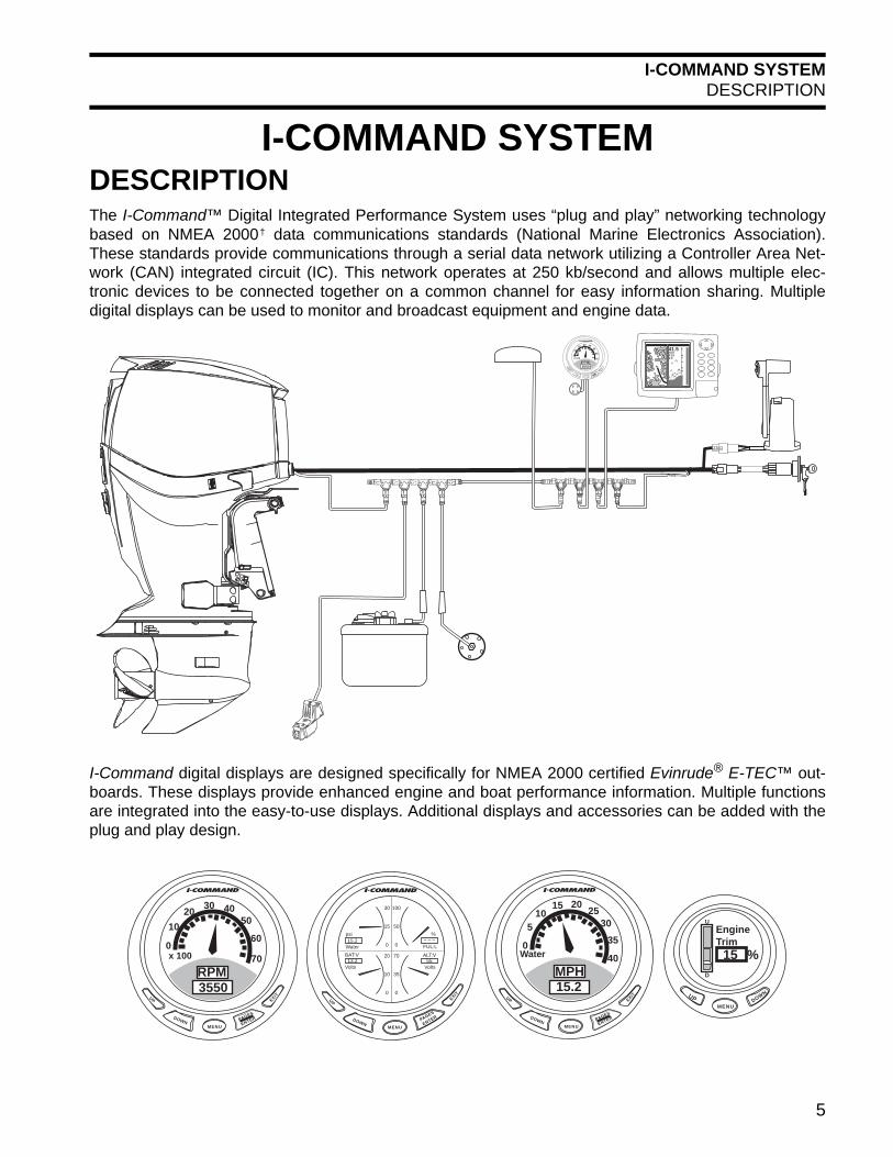
I-COMMAND SYSTEMDESCRIPTIONThe I-Command™ Digital Integrated Performance System uses “plug and play” networking technologybased on NMEA 2000† data communications standards (National Marine Electronics Association).These standards provide communications through a serial data network utilizing a Controller Area Net-work (CAN) integrated circuit (IC). This network operates at 250 kb/second and allows multiple elec-tronic devices to be connected together on a common channel for easy information sharing. Multipledigital displays can be used to monitor and broadcast equipment and engine data.
I-Command digital displays are designed specifically for NMEA 2000 certified Evinrude® E-TEC™ out-boards. These displays provide enhanced engine and boat performance information. Multiple functionsare integrated into the easy-to-use displays. Additional displays and accessories can be added with theplug and play design.
MENU
DOWN
UP EXIT
PAGES
ENTER
302010
0
4050
60
70x 100
RPM3550
41.572.00.192.0
MENU
DOWN
UP EXIT
PAGES
ENTER
Water
psi15.2
BAT:V
Volts13.2
FUL:L
%– – –
Volts
ALT:V55
30
15
0
20
10
0
100
50
0
70
35
0
MENUDOWNUP
EngineTrim15 %
U
D
MENU
DOWN
UP EXIT
PAGES
ENTER
1510
5
0
20 2530
35
40Water
MPH15.2
MENU
DOWN
UP EXIT
PAGES
ENTER
302010
0
4050
60
70x 100
RPM3550
5

I-COMMAND SYSTEMI-COMMAND “DIGITAL” SERIES FEATURES
I-COMMAND “DIGITAL” SERIES FEATURES
I-Command“Digital” SeriesMultifunction
3 ½ in. and 2 in. Displays
3 ½ in. Display 2 in. Display
Functions & Screen DisplaysSystem Setup
Adjustable Display Contrast and AudioEngine Warning Displays
Single, Dual or Quad Page Display Single or Dual Page Display
Displays in English or Metric UnitsMulti Engine RPM on Single Page Display (two or three engines)
TachometerSpeedometer(1)or(2)
GPS Position Longitude and Latitude(1)
GPS Time(1)
Engine Hour MeterEngine Trim Position(3)
Engine TemperatureWater Pressure(4)
Alternator voltage (Evinrude E-TEC - 55 volt system)Battery voltage
Engine Load – percent of throttleTemperature(5) Sensor (water / air / fluid – limit three)
Barometric PressureFuel Tank Level(6)or(9)or(10) (three tank/engine limit)
Oil Tank Level(7) (three tank limit)Depth(8)
Fuel Flow Rate(9) (three engine limit)Fuel Consumption(9)and(10)
Fuel Economy and Range(1)and(10) (three engine limit)
Fuel Remaining and Fuel Used(6)and, or(10)
Low Fuel Warning – programmableTrip Fuel and Seasonal Fuel(10)
(1) Requires NMEA 2000 GPS receiver/antenna connected to network. Provides speed over ground (SOG).(2) Requires water speed input device - provides speed over water (SOW). (3) Available on V4/V6 Evinrude E-TEC outboards. (Not available on 25 HP through 90 HP Evinrude E-TEC.)(4) Requires accessory water pressure transducer kit.(5) Requires NMEA 2000 depth transducer/triducer with temperature output or temperature sensor kit(s).(6) Requires accessory fuel tank level converter for each tank. See “Select Fuel Remaining Source” on page 33.(7) Requires accessory oil tank sending unit kit for each oil tank.(8) Requires NMEA 2000 depth transducer.(9) Requires EMM interface.(10) Requires memory module. See “Select Fuel Remaining Source” on page 33.
MENU
DOWN
UP EXIT
PAGES
ENTER
Water
psi15.2
BAT:V
Volts13.2
FUL:L
%– – –
Volts
ALT:V55
30
15
0
20
10
0
100
50
0
70
35
0
MENUDOWNUP
EngineTrim15 %
U
D
6

I-COMMAND SYSTEMI-COMMAND “DIGITAL” DISPLAYS
I-Command “Digital” Displays
Digital Display (black bezel)
3 ½ in. 2 in.
764175(1) 764177(1)
764176(1)(2) 764178(1)(2)
(1) Includes T-connector, PN 764151(2) Includes adaptor, PN 764187
Accessory Bezels 3 ½ in. 2 in. Gold 764011 764610White 764013 764012
Chrome 764640 764641Black 764595 764594
Trim Rings 3 ½ in. 2 in. Blue 764257 764256Red 764259 764258
Black 764261 764260White 764263 764262Gold 764265 764264
Chrome 764267 764266Platinum 764269 764268
7

I-COMMAND SYSTEMNETWORK SPECIFICATIONS
NETWORK SPECIFICATIONS
Cable RequirementsNMEA 2000 specifies wire requirements as fol-lows:
NMEA 2000 specifies wire colors as follows:
GroundingThe network should be grounded at a SINGLElocation. This is normally done at the power sup-ply connection to the network and should berobustly connected to the boat’s grounding sys-
tem. There must be no other ground connectionson the network to avoid ground loops, which cancause problems with network performance.
Maximum Number of DevicesA maximum of 50 devices can be attached to aNMEA 2000 network.
Load EquivalencyThe Engine Management Module (EMM) onEvinrude E-TEC outboards has a load equiva-lency number of 1. Less than 50 mA of the net-work’s (CAN) power is used by the EMM.
Linear ArchitectureNMEA 2000 networks use a “linear” architecture.Linear describes the network buss as connectedin a line. This design is easy to assemble andexpand. The linear architecture must be main-tained whenever an additional device is added tothe network or the network is modified. This typeof network also requires one terminator at eachend of the network buss. Connect buss cables, terminators, and T-connec-tors to the buss connectors (side connectors) ofthe T-connectors. Connect devices to the deviceconnector (center point) of the T-connector.
6M (19 ft.)maximum
100M (328 ft.) Maximum Network Buss Length
Device cables Device cable
Buss cable(Network Buss)
Power supply& Groundconnection
Terminator TerminatorNMEA2000®
Device
NMEA2000®
Device
NMEA 2000 Network DiagramNMEA2000®
Device
NMEA2000®
Device
NMEA2000®
Device
NMEA2000®
Device
NMEA 2000 Cable (Light / Micro Buss) Maximum Current 4 AMPS
Resistance - Power Wire(s) 5.40 Ω per 100 MPower Wire Size 22 AWGData Wire Size 24 AWG
NMEA 2000 Wire Designation ColorPower supply (+VDC) Red
Ground (–VDC) BlackShield (Drain) Bare
Data HI (Signal) WhiteData LOW (Signal) Blue
8

I-COMMAND SYSTEMNETWORK SPECIFICATIONS
Network Buss LengthThe distance between any two points on the net-work must not exceed 100 meters (328 ft.). Measure the distance from the T-connector to thelast device at each end of the network. Device cable lengths at the ends of the networkmust be included in the total network buss lengthcalculation.
Device Cable LengthsNetwork device cable lengths:• Must not exceed 6 meters (19 ft.) for single
device cable lengths• Must not exceed 78 meters (256 ft.) for total
device cable lengths
Open Network Device ConnectorsRemove T-connectors to eliminate “open” networkdevice connectors. There should be no “open” orunused network device connectors.
G P S R E C E I V E R
MENU
DOWN
UP EXIT
PAGES
ENTER
302010
0
4050
60
70x 100
RPM3550
Network Buss Length Diagram
9

I-COMMAND SYSTEMQUICK CONNECT STYLE CONNECTORS
QUICK CONNECT STYLE CONNECTORSConnector Identification Connectors have two configurations – Male (pins)and Female (sockets).
Terminating ResistorsTerminating resistors are required for accuratenetwork transmissions. Networks must be assem-bled with terminators positioned at both ends ofthe network buss. Each terminator uses a 120 Ω,1/4 watt resistor to terminate data transmissionson the network.One terminator must be installed at each end ofthe I-Command network.
T-Connectors and Buss CablesT-connectors provide device access to the net-work. T-connectors have two buss connectors andone device connector. Network devices must be
connected to the device connector of the T-con-nector.
T-connectors can be installed at the end of a net-work. Connect a network buss cable to one sideand a terminator into the other
Multiple T-connectors can be installed in the mid-dle or the end of a network. Use network busscables to connect T-connectors
IMPORTANT: An engine interface cable isrequired to connect an Evinrude E-TEC outboardto the network.
DeviceNet™ style1. Shield (Drain) - Bare wire2. Power (+VDC) - Red wire3. Ground (–VDC) - Black wire4. Data HI (Signal) - White wire5. Data LOW (Signal) - Blue wire
DeviceNet™ style) terminators
12
3 45
12
3 45
Male (Pins) Female (Sockets)
Male (Pins)Female (Sockets)
DeviceNet™ style1. Male buss connector2. Female buss connector3. Female device connector
1. Buss cable2. Terminator
1. Buss cable2. T-connectors
DEV
ICE
BUSS1
3
2
DEV
ICE
DEV
ICE
BUSS BUSS
12
DEV
ICE
DEV
ICE
BUSS BUSS
DEV
ICE
DEV
ICE
BUSS BUSS
DEV
ICE
DEV
ICE
BUSS BUSS
DEV
ICE
DEV
ICE
BUSS BUSS
DEV
ICE
DEV
ICE
BUSS BUSS
DEV
ICE
DEV
ICE
BUSS BUSS
DEV
ICE
DEV
ICE
BUSS BUSS
DEV
ICE
DEV
ICE
BUSS BUSS
2 1 2 1 2
10

I-COMMAND SYSTEMQUICK CONNECT STYLE CONNECTORS
1. Power harness, single engine2. Terminator (Male)3. Terminator (Female)4. T-Connector
5. Buss cable 6. Engine Interface Cable (network to E-TEC outboard)7. Power harness, multi-engine
DEV
ICE
DEV
ICE
BUSS BUSS
6
32 5
4
1
43A
DEV
ICE
DEV
ICE
BUSS BUSS
DEV
ICE
DEV
ICE
BUSS BUSS
DEV
ICE
DEV
ICE
BUSS BUSS
DEV
ICE
DEV
ICE
BUSS BUSS
DEV
ICE
DEV
ICE
BUSS BUSS
54
SINGLE OUTBOARD
TWIN OUTBOARD
32 5
44
3A
DEV
ICE
DEV
ICE
BUSS BUSS
DEV
ICE
DEV
ICE
BUSS BUSS
DEV
ICE
DEV
ICE
BUSS BUSS
DEV
ICE
DEV
ICE
BUSS BUSS
DEV
ICE
DEV
ICE
BUSS BUSS
DEV
ICE
DEV
ICE
BUSS BUSS
DEV
ICE
DEV
ICE
BUSS BUSS
4
766
5
11
I-COMMAND SYSTEMQUICK CONNECT COMPONENTS
QUICK CONNECT COMPONENTS
DEV
ICE
DEV
ICE
BUSSBUSS
12
3
4
5
6
3A
3A
7
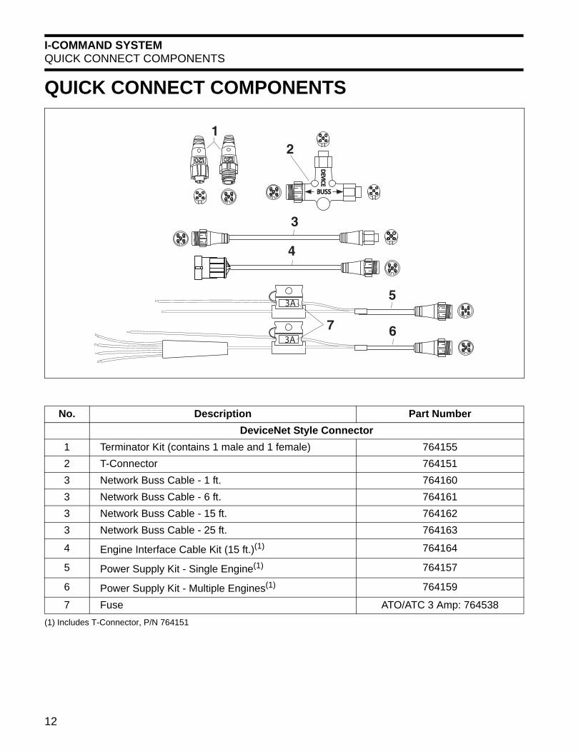
No. Description Part NumberDeviceNet Style Connector
1 Terminator Kit (contains 1 male and 1 female) 7641552 T-Connector 7641513 Network Buss Cable - 1 ft. 7641603 Network Buss Cable - 6 ft. 7641613 Network Buss Cable - 15 ft. 7641623 Network Buss Cable - 25 ft. 764163
4 Engine Interface Cable Kit (15 ft.)(1) 764164
5 Power Supply Kit - Single Engine(1) 764157
6 Power Supply Kit - Multiple Engines(1) 764159
7 Fuse ATO/ATC 3 Amp: 764538(1) Includes T-Connector, P/N 764151
12

I-COMMAND SYSTEMIGNITION AND TRIM/TILT HARNESSES
IGNITION AND TRIM/TILT HARNESSESIMPORTANT: Do not use a MWS harness (orany other harness) in place of an I-Command Igni-tion and Trim/Tilt Harness or an I-Command Igni-tion and Trim/Tilt Adaptor Harness. TheseI-Command harnesses are built with 47 ohmresistors for the trim sender circuit and provide aswitched B+ circuit for EMM operation.
Ignition and Trim/Tilt HarnessOutboards rigged with I-Command use a uniqueIgnition and Trim/Tilt Harness. This harness pro-vides a switched B+ connection for the EMM Har-ness and a 47 ohm resistor for the trim sendercircuit.
The Ignition and Trim/Tilt Harness is offered invarious lengths and engine configurations. Single,twin and triple engine configurations are available.All twin and triple harnesses require the use ofone Ignition and Trim/Tilt Adaptor Harness foreach outboard. See Ignition and Trim/Tilt Adap-tor Harness – Used for Two and Three EngineInstallations on p. 13
Ignition and Trim/Tilt Adaptor Harness – Used for Two and Three Engine Installations The Ignition and Trim/Tilt Adaptor Harness is usedfor twin and triple engine installations and con-nects to the outboard and a twin or triple Ignitionand Trim/Tilt Harness. This required harness
includes the 47 ohm resistor for the trim sendercircuit.
TO OUTBOARD
PURPLE WIRESWITCHED B+
TO OUTBOARD
13

I-COMMAND SYSTEMIGNITION AND TRIM/TILT HARNESSES
1
2
3
No. Description Part Number
Harness Lengths 12 ft. 15 ft. 20 ft. 25 ft. 28 ft.
1 Singe OutboardIgnition and Trim/Tilt Harness 763542 763543 763544 763545 763546
2
Twin OutboardIgnition and Trim/Tilt Harness 763547 763548 763549
Triple OutboardIgnition and Trim/Tilt Harness(1) 763550 763551
3 Ignition and Trim/Tilt Adaptor Harness(2) 6 ft. - 763552 or 10 ft. - 763553
(1) Not shown(2) Must be used with Twin Outboard Ignition and Trim/Tilt Harness and Triple Outboard Ignition and Trim/Tilt Harness to connect
to outboards. Use one Ignition and Trim/Tilt Adaptor Harnesses for each outboard (contains 47 ohm 1/4 watt resistor for trimsender circuit).
14

I-COMMAND SYSTEMIGNITION AND TRIM/TILT WIRING DIAGRAMS
IGNITION AND TRIM/TILT WIRING DIAGRAMS
KEY SWITCH
IGN IGN
TWIN ENGINE
IGNITION /TRIM/TILT ADAPTOR HARNESS (USE ONE FOR EACH OUTBOARD)
PURPLE WIRE (SWITCHED B+)
NOTE: Multiple engine ignition/trim/tilt harnesses are avaialble in various lengths.
BLACK WIRE (GROUND)
SINGLE ENGINE
KEY SWITCH
IGNITION/TRIM/TILT HARNESS
IGNITION/TRIM/TILT HARNESS
OUTBOARD TRIM TILT CONNECTOR
OUTBOARD IGNITION CONNECTOR
BLACK WIRE (GROUND) PURPLE WIRE (SWITCHED B+)
PURPLE WIRE (SWITCHED B+)
Not used on I-Command Digital Systems
Not used on I-Command Digital Systems
15

I-COMMAND SYSTEMACCESSORIES
ACCESSORIESVarious NMEA 2000 accessories are available to interface to the I-Command Digital System. This isachieved by adding an additional tee connector to the network buss.
Description of Kit P/NTriducer, transom mount, Speed/Depth/Temp 764334(1)
Triducer, thru-hull, Plastic, Speed/Depth/Temp 764336(1)
Transducer, transom mount, Depth/Temp (No speed) 764335(1)
GPS Receiver/antenna 764179(1)
SOW Paddle Wheel Kit 764193(1)
Water Speed /Pressure Sensor Kit 764195(1)
Memory Module Kit (Fuel Manager) 764181(1)
Fluid Level Converter (unconfigured) 764166(1)(2)(3)
Fuel Level Converter Kit – one fuel tank (instance 0) 764168(1)(4)
Fuel Level Converter Kit – two fuel tanks (instance 0 and 1) 765047(1)(4)
Fuel Level Converter Kit – three fuel tanks (instance 0, 1 and 2) 765051(1)(4)
Fuel Flow / Level Transducer Kit 764191(1)(2)(4)
Oil Tank Level Kit, 1.8 Gallon – one engine one oil tank (instance 0) 764271(1)(4)
Oil Tank Level Kit, 1.8 Gallon – two engines two oil tanks (instance 0 and 1) 764273(1)(4)
Oil Tank Level Kit, 3.0 Gallon – one engine one oil tank (instance 0) 764272(1)(4)
Oil Tank Level Kit, 3.0 Gallon – two engines two oil tanks (instance 0 and 1) 764274(1)(4)
Oil Tank Level Kit, 3.0 Gallon – three engines three oil tanks (instance 0, 1 and 2) 764275(1)(4)
Oil Tank Level Converter Kit, 10 Gallon – one oil tank (instance 0) 763737
Engine Water Pressure Sensor – (See “Engine Water Pressure Sensor Kit” on page 20) 5008300(3)
NMEA 2000 Pressure Sensor Kit – (See “NMEA 2000 Pressure Sensor Kits” on page 20) 765038(1)(2)(4)
Temperature Sensor (water / air / fluid – unconfigured) 764183(1)(2)
3.5 inch I-Command Gauge Horn and Hardware Kit 764593
2 inch I-Command Gauge Horn and Hardware Kit 764676
(1) Includes T-connector(s), P/N 764151(2) Configure using I-Command Digital display(3) Configure using Evinrude Diagnostics software(4) Connect to specific engine or accessory for correct network data to be displayed (Instance 0, 1, or 2)
16

I-COMMAND SYSTEMACCESSORIES
Instance NumbersI-Command networks (NMEA 2000) allow multipleelectronic devices to be connected together on acommon network and can be configured to sup-port many instances of duplicate or similardevices on the same network.
Device identities and instance numbers are usedto identify devices on a network.
Additional devices (accessories) are addedthrough careful network configuration.
Refer to “NETWORK SETUP” on page 32” orI-Command User’s Guides for engine and boatsetup, fuel tank setup, oil tank setup, pressuresensor setup, and temperature sensor setup.
Engines are identified from PORT to STAR-BOARD on the transom. See instance numbers inchart.
Fuel and oil tanks must be connected to the cor-rect converter to provide accurate I-Commandnetwork information. Label converters and wiringby instance number (engine location or devicelocation).
Identify water pressure sensors and temperaturesensors; and accurately label converters and wir-ing by instance number (engine location or devicelocation).
Number of Outboards
Instance Number
Port
Star
boar
d or
Cen
ter
Star
boar
d
1 02 0 13 0 1 2
Device Description(1) Instance Number Engine Location or Device Location
Is Device Configured on
Network
Engine 1 0 Port YESEngine 2 1 Starboard or Center YESEngine 3 2 Starboard YESFuel Tank 1 0 Main fuel tank or tank 1 YESFuel Tank 2 1 Auxiliary fuel tank or tank 2 –Fuel Tank 3 2 Auxiliary fuel tank 2 or tank 3 –Oil Tank 1 0 Label oil tank 1 YESOil Tank 2 1 Label oil tank 2 –Oil Tank 3 2 Label oil tank 3 –
Engine Water Pressure Sensor Use Evinrude Diagnostics Port, Center, Starboard NO
NMEA 2000 Pressure Sensor 1 0 Port YESNMEA 2000 Pressure Sensor 2 1 Starboard or Center YESNMEA 2000 Pressure Sensor 3 2 Starboard YESTemperature Sensor 1 0 Port or device location YESTemperature Sensor 2 1 Starboard / Center or device location –Temperature Sensor 3 2 Starboard or device location –
(1) This chart provides device descriptions and instance numbers on a typical I-Command network andrepresents a boat assembled with three (3) engines.
17

I-COMMAND SYSTEMACCESSORIES
Fuel Tank Level Converter KitsFuel tank level converter kits contain the fuel tanklevel converter(s) needed for specific I-Commandnetwork installations. Use the chart below toselect the required kit or converter.
Fuel tank level converters (analog to digital con-verters) must be installed to coincide with fuel tankinstance (position). Refer to user information andsetup information to reconfigure the instance num-bers of converters. See “Instance Numbers” onpage 17.
Fluid Level ConvertersFluid level converters (analog to digital convert-ers) must be configured to provide proper input tothe I-Command network. Fluid level convertersmust be configured to support a specific sendingunit. Select fluid level converter(s) for fuel level, oillevel, and water level as needed. Fluid level con-verters must be configured to support I-CommandDigital displays. Refer to user information andsetup information to reconfigure the instance num-bers of converters. See “Instance Numbers” onpage 17.
Memory Module KitA memory module kit provides fuel level and fuelmanagement data for the I-Command network.Use with I-Command Digital displays ONLY.
Number of Fuel Tanks
Fuel Tank Level
Converter Kit P/N
Fuel Tank
Converter Instance
Converter P/N
1 764168(1)(2)
(1) Includes T-connector(s), P/N 764151 (2) Connect the fuel tank level converter configured with the
appropriate instance number to the specific fuel tanksending unit.
0 764168(1)(2)
2 765047(1)(2)0 764168(1)(2)
1 764170(1)(2)
3 765051(1)(2)
0 764168(1)(2)
1 764170(1)(2)
2 765044(1)(2)
EP-15 Fuel Oil 0 1 2 3
DEV
ICE
DEV
ICE
BUSSBUSS Length12 ft. / 3.7 m
Fluid Level Converter P/N
Unconfigured 764166(1)(2)
(1) Includes T-connector, P/N 764151(2) Configure with I-Command Digital display
Memory Module KitP/N
764181(1)
(1) Includes T-connector, P/N 764151
EP-15 Fuel Oil 0 1 2 3
DEV
ICE
DEV
ICE
BUSSBUSS Length12 ft. / 3.7 m
EP- 85 Memory Module
DEV
ICE
DEV
ICE
BUSSBUSS
Length2 ft. / 0.6 m
18

I-COMMAND SYSTEMACCESSORIES
Oil Tank Level KitsI-Command oil tank level kits include oil tanksending unit(s) and oil tank level converter(s).
Oil tank level converters (analog to digital convert-ers) provide oil tank information to the I-Commandnetwork and must be installed to coincide with oiltank instance (position). Refer to user informationand setup information to reconfigure the instancenumbers of converters. See “Instance Numbers”on page 17.
Oil Tank Level ConvertersA 10 gallon oil level converter kit is used in a sin-gle or a multiple engine installation which use onecommon oil tank. The oil level converter suppliedwith this kit is instance “I0”.
Oil tank level converters must be installed to coin-cide with engine and oil tank instance (position).Refer to user information and setup information toreconfigure the instance numbers of converters.See “Instance Numbers” on page 17.
Number of Oil Tanks
Number of Sending
Units and Converters Included in
Kit
Oil Tank Level
Converter Instance
Kit P/N
1.8 Gallon Oil Tank Level Kits1 1 0 764271(1)(2)
(1) Kit includes T-connector(s), P/N 764151(2) Install the oil tank sending unit kit with the pre-configured
oil tank level converter(s) in the appropriate oil tank. See“Oil Tank Level Converters” on page 19
2 20
764273(1)(2)1
3.0 Gallon Oil Tank Level Kits
1 1 0 764272(1)(2)
2 20
764274(1)(2)1
3 3
0
764275(1)(2)1
2
1. Sending Unit2. Converter3. T-connector
DEV
ICE
DEV
ICE
BUSSBUSS 3
12
10 Gallon Oil Tank Level Converter KitNumber of Converters
Included in Kit Instance Converter P/N
1 0 763737
OutboardInstance Engine Position Converter
P/N
0Single engine
764171Port engine on two orthree engine installation
1
Starboard engine ontwo engine installation
764172Center engine on threeengine installation
2Starboard engine onthree engine installation 764173
Unconfigured 764166(1)
(1) Configure using the I-Command Digital display
EP-15 Fuel Oil 0 1 2 3
Length12 ft. / 3.7 m
19
I-COMMAND SYSTEMACCESSORIES
Oil Tank Sending UnitsOil tank sending units below are used to serviceI-Command digital oil tank sending unit kits.
Engine Water Pressure Sensor KitAn engine water pressure sensor kit provideswater pressure input to the outboard’s EMM. Thisinput is processed by the EMM of the outboardthen broadcast to the I-Command network. Usedon 115 HP and larger Evinrude E-TEC outboardsonly. Configure this sensor using Evinrude Diag-nostics software program. See “NETWORKSETUP” on page 32.
NMEA 2000 Pressure Sensor KitsNMEA 2000 pressure sensor kits can be used toprovide data for engine water pressure, fuel pres-sure, engine boost pressure, engine oil pressure,or transmission oil pressure. DO NOT mount thissensor under the engine cover. Refer to userinformation and setup information to reconfigurethe instance numbers of converters. See“Instance Numbers” on page 17.
Sending Unit Height P/N
6.5 in. (1.8 gallon tank) 763407(1)
(1) An oil tank level converter is required to connect to net-work
8.5 in. (3.0 and 10 gallon tank) 763408(1)
Engine Water Pressure Sensor Kit
P/N
5008300(1)
(1) Configure using Evinrude Diagnostics software program
Sensors (Converters) Included in
Kit
Sensor Converter Instance
Kit P/N
1 0 765038(1)(2)(3)
(1) Kit includes T-connector, P/N 764151(2) Install the pressure sensor kit with the pre-configured
pressure sensor converter(s) in the appropriate location (3) Configure using the I-Command Digital display if needed
1 1 765040(1)(2)(3)
1 2 765042(1)(2)(3)
DEV
ICE
DEV
ICE
BUSSBUSS
Length12 ft. / 3.7 m
20

I-COMMAND SYSTEMACCESSORIES
GPS Receiver/AntennaThese NMEA 2000 GPS receivers provide “loca-tion” and “speed over ground” (SOG) input to theI-Command network.
Network buss harnesses can be used to extendand make connections.
Transducers and TriducersTransducers provide depth and temperatureinputs to the I-Command network.
Triducers provide depth, temperature and “speedover water” (SOW) inputs to the I-Command net-work.
IMPORTANT: Installations using I-CommandClassic instruments require a Multifunction I-Com-mand Classic Speedometer.
GPS Receiver/Antenna (NMEA 2000)
P/N
764179
G P S R E C E I V E R3
Length12 in. / 30cm
Transducers (NMEA 2000) P/N
Transom Mount Transducer 764335
Transom Mount Triducer 764334
Thru-Hull Triducer 764336
Transom Mount Transducer
Thru-Hull Triducer (plastic)
Length12 ft. / 3.7 m
Length12 ft. / 3.7 m
21

I-COMMAND SYSTEMACCESSORIES
Speed Transducer - Paddle WheelA transom mount paddle wheel provides speedover water (SOW) input to the I-Command net-work.
Temperature Sensor KitA temperature sensor kit provides air or fluid tem-perature. The sensor range is 4° to 176°F (-20° to80°C).
Fuel Flow Transducer KitFuel flow transducer kits provide fuel flow data tothe network.
IMPORTANT: DO NOT use on 40 - 300 HPEvinrude E-TEC outboards. Speed Transducer
(NMEA 2000)P/N
764193
Temperature Sensor KitP/N
764183(1)
(1) Configure using I-Command Digital display
DEV
ICE
DEV
ICE
BUSSBUSS
Length12 ft. / 3.7 m
EP- 35 TEMP
DEV
ICE
DEV
ICE
BUSSBUSS Length12 ft. / 3.7 m
Fuel Flow Transducer KitP/N
764191(1)
(1) Configure using I-Command Digital display
DEV
ICE
DEV
ICE
BUSSBUSS
Length12 ft. / 3.7 m
22

I-COMMAND INSTALLATIONINSTRUMENTS
I-COMMAND INSTALLATIONINSTRUMENTSSpacing of InstrumentsThe minimum distances between instruments on apanel should be as follows:• 3 13/16 (112 mm) center to center for 3 1/2 in.
instruments• 3 1/4 in. (95.5 mm) center to center for 3 1/2 in.
instruments to 2 in. instruments• 2 5/8 in. (77 mm) center to center for 2 in.
instruments
Panel ThicknessInstruments can be mounted in panels up to 1 in.thick.
Hole SizesIMPORTANT: Check space behind panel to besure adequate clearance for instruments existsbefore drilling panel.
3 1/2 in. Multifunction GaugeCut 3 3/8 in. (99 mm) diameter hole in panel for 31/2 in. instruments. Secure instrument with nutsand bracket.
2 in. GaugeCut 2 1/16 in. (52 mm) diameter hole in panel for 2in. instruments. Secure instrument with spin nut.
Fastening to PanelInsert instrument into panel hole. Thread spin nutonto threaded housing of instrument and tightento back of panel. DO NOT exceed 10 in. lbs. (1.1N·m) If stud and bracket kits are used, tighten nutsfinger tight.
Warning HornConnect the yellow wire from the instrument to theblack wire of the warning horn. Connect the bluewire from the instrument to the red wire of thewarning horn.
Each instrument should be installed with a warn-ing horn. Mount each warning horn in a protectedarea (out of the weather) and so horn is audiblefor operator.
Navigation LightsConnecting the light wiring for the I-Commandinstrument to the boat’s navigation lights will pro-vide instrument lighting if the instrument backlightsetting is set to lowest setting and the boat’s navi-gation lights are turned ON.
Connect the white wire from the instrument to theswitched positive (B+) of the boat’s navigationlights and the black wire from the instrument toground (GND).
1. Warning horn
1
23

I-COMMAND INSTALLATIONINSTRUMENTS
Instrument Dimensions3 1/2 in. Digital Series Multifunction Display
2 in. Digital Series Multifunction Display
3.34 in.(85 mm)
2.20 in.(56 mm)
2.87 in.(72.9 mm)
0.71 in.(18 mm)
3.81 in.(96.9 mm)
1.95 in.(49.5 mm)
2.36 in.(60 mm)
2.0 in.(51 mm)
.54 in.(13.6 mm)
2.08 in.(53 mm)
24

I-COMMAND INSTALLATIONQUICK CONNECT NETWORK COMPONENTS
QUICK CONNECT NETWORK COMPONENTSDeviceNet-Style T-Connector DimensionsSome T-connectors have different dimensions.
Mounting DeviceNet-Style T-ConnectorsMount T-connectors to flat mounting surfaces. Use washers or spacers behind the T-connector asneeded. Check T-connector alignment. Incorrect mounting can damage the T-connectors resulting inbroken wiring connections. T-connectors should be mounted with the “Device” connector facing down toprevent water intrusion. Tighten screws by hand to prevent damage. Groups of T-connectors can bestacked for mounting in larger network installations.
Converter/Memory Module Dimensions
DEV
ICE
DEV
ICE
BUSSBUSS
3/16 in.(4.76 mm)
1.87 in.(47.5 mm) 0.813 in.
(21 mm)
INCORRECT
CORRECT
CORRECT
CONNECTORS ARE DAMAGED
3.44 in.(87 mm)
0.79 in. (20 mm)
25

I-COMMAND INSTALLATIONQUICK CONNECT NETWORK
QUICK CONNECT NETWORKLubricate all connector gaskets with ElectricalGrease (dielectric) before assembly.
Refer to “QUICK CONNECT NETWORK DIA-GRAMS” on page 28.
1) Install ignition and trim/tilt wire har-ness.
Ignition and trim/tilt harnesses are available in var-ious lengths. Refer to “IGNITION AND TRIM/TILTHARNESSES” on page 13.
Ignition and trim/tilt harnesses are available in var-ious lengths for twin or triple engine installations.Use one ignition trim/tilt adaptor harness for eachoutboard connecting to a twin or triple configura-tion ignition and trim/tilt harness.
2) Organize the components required forthe installation.
Position components, identify harness routings,and determine locations for T-connectors. All net-work devices are installed by adding T-connec-tors.
3) Install power supply and T-connector. The I-Command network must be connected to aswitched power source.
Single Engine Power Supply Harness: Connectthe red wire of the power supply harness to thepurple switched B+ accessory wire of the ignitionand trim/tilt wire harness. Connect the black wireof the power harness to the black ground wire ofthe ignition and trim/tilt harness.
Multiple Engine Power Supply Harness: Con-nect the purple wire(s) of the power supply har-ness to the purple switched B+ accessory wires ofthe ignition and trim/tilt wire harness(s). Connecteach black wire of the power harness to a blackground wire of the ignition and trim/tilt harness.(Optional: connect the red wire of the power har-ness to a switched B+ power supply of the boat.)
Connect the network connector of the power sup-ply harness to the device connector of the T-con-nector. Connect data cables, additional
T-Connectors or a terminator to the buss connec-tors of the T-connector.
4) Connect I-Command instrument(s).Add T-connectors to network as needed. Use oneT-connector for each instrument. Connect thequick connect connector(s) from instrument(s) tothe device connector of the T-connector.
5) Install the Engine Interface cable andT-connector.
The outboard connects to the I-Command networkas a device. Connect the 4-pin CANBus connectorof the engine interface cable to the outboard.Route the 15 ft. (4.6 m) cable with the ignition andtrim harness into the boat.
Install the T-connector for the engine interface onthe network. Connect the quick connect connectorfrom engine interface cable to the device connec-tor of the T-connector.
For multiple outboards, install an additional T-con-nector and engine interface cable for each out-board.
Remember to install a terminator to the open endof the T-connector if it is the last buss connectoron the network.
6) Connect buss cable(s).Use buss cables to extend the network’s lengthand to connect T-connectors. Buss cables have amale connector on one end and a female connec-tor on the other.
Use the appropriate length buss cable to connectthe T-connector group at the helm or console with
1. Terminators
1 1
DEV
ICE
DEV
ICE
BUSS BUSS
DEV
ICE
DEV
ICE
BUSS BUSS
DEV
ICE
DEV
ICE
BUSS BUSS
DEV
ICE
DEV
ICE
BUSS BUSS
DEV
ICE
DEV
ICE
BUSS BUSS
DEV
ICE
DEV
ICE
BUSS BUSS
DEV
ICE
DEV
ICE
BUSS BUSS
DEV
ICE
DEV
ICE
BUSS BUSS
26

I-COMMAND INSTALLATIONQUICK CONNECT NETWORK
T-connectors positioned along the length of thehull.
Use buss cables to extend the cable lengthsbetween a device and a T-connector on the net-work. Limit total “drop” length to 19 ft. (6 m). Referto “NETWORK SPECIFICATIONS” on page 8
7) Adding a network device.Other devices, such as another I-Command Digi-tal gauge, an auxiliary fuel tank level sensor, or aGPS sensor can be added anywhere along thenetwork buss.
Add a T-connector at the end of the network(between a T-connector and a terminator),between two T-connectors, or between a T-con-nector and a data cable.
Add a new device by connecting device cableconnector to the device (center) connector ofT-connector.
8) Install fluid level converters.I-Command fluid level converters convert thestandard analog electrical signal of sending unitsto the NMEA 2000 signal.
Remove excess cable length when connectingconverters to sending units.
IMPORTANT: If multiple “unconfigured” fluidlevel converters are installed, refer to “NETWORKSETUP” on page 32. Connect one fluid level con-verter to the network and configure converter.Once first converter is configured, connect secondconverter and configure. Continue connecting andconfiguring converters one at a time.
Fuel Tank Level ConverterConnect the red wire of the converter to the fueltank sending unit’s positive terminal (pink wire).
Connect the black wire (ground) of the converterto the sending unit’s ground (–) terminal.
Connect the fuel level converter connector to thedevice (center) connector of the T-connector.
9) Install terminators.Connect the appropriate terminator to the openbuss connector of the T-connector at both ends ofthe network.
10) Set outboard identityFor the outboard, run the latest version ofEvinrude Diagnostics program and assign the out-board an identity for the network. Refer to“Instance Numbers” on page 17 and use EvinrudeDiagnostics software to complete procedure. Thisprocedure is required for multi-engine installa-tions.
11) Check operation.Complete programming of the I-Command Net-work using an I-Command Multifunction Instru-ment. Refer to “NETWORKTROUBLESHOOTING CHART” on page 34 andthe I-Command User’s Guide for setup proce-dures.
12) Carefully route and secure all har-nesses, converters, adaptors, andT-connectors.
Once network is assembled and functional, posi-tion all harnesses and components carefully toprevent abrasion or contact with moving objects.T-connectors can be fastened with screws. Har-nesses, converters, memory devices, and adap-tors should be fastened using tie straps.
EP-15 Fuel Oil 0 1 2 3
DEV
ICE
DEV
ICE
BUSSBUSS
1. Positive terminal2. Ground terminal
12
27

I-COMMAND INSTALLATIONQUICK CONNECT NETWORK DIAGRAMS
QUICK CONNECT NETWORK DIAGRAMS
SINGLE OUTBOARD
BUSS BUSS
DEV
ICE
DEV
ICE
DEV
ICE
DEV
ICE
DEV
ICE
DEV
ICE
BUSS BUSS
POWER SUPPLYHARNESS
NETWORK BUSS CABLE
ENGINE INTERFACE CABLE
TERMINATOR
TERMINATOR
T-CONNECTORS
DEVICECONNECTIONS
DEVICECONNECTIONS
3A
DEV
ICE
DEV
ICE
BUSS BUSS
DEV
ICE
DEV
ICE
BUSS BUSS
DEV
ICE
DEV
ICE
BUSS BUSS
DEV
ICE
DEV
ICE
BUSS BUSS
DEV
ICE
DEV
ICE
BUSS BUSS
NETWORK BUSS CABLE
MENU
DOWN
UP EXIT
PAGES
ENTER
302010
0
4050
60
70x 100
RPM3550
TWIN OUTBOARDS
DEV
ICE
DEV
ICE
BUSS BUSS
ENGINE INTERFACE CABLES
TERMINATOR TERMINATOR
3A
T-CONNECTORS
POWER SUPPLYHARNESS
DEVICECONNECTIONS
DEVICECONNECTIONS
DEV
ICE
DEV
ICE
BUSS BUSS
DEV
ICE
DEV
ICE
BUSS BUSS
DEV
ICE
DEV
ICE
DEV
ICE
DEV
ICE
BUSS BUSS
DEV
ICE
DEV
ICE
BUSS BUSS
DEV
ICE
DEV
ICE
BUSS BUSS
DEV
ICE
DEV
ICE
BUSS BUSS
DEV
ICE
DEV
ICE
BUSS BUSS
DEV
ICE
DEV
ICE
BUSS BUSS
NETWORK BUSS CABLE NETWORK BUSS CABLE
MENU
DOWN
UP EXIT
PAGES
ENTER
302010
0
4050
60
70x 100
RPM3550
MENU
DOWN
UP EXIT
PAGES
ENTER
302010
0
4050
60
70x 100
RPM3550
TRIPLE OUTBOARDS
DEV
ICE
DEV
ICE
BUSS BUSS
ENGINE INTERFACE CABLES
TERMINATOR TERMINATORT-CONNECTORS
3A
POWER SUPPLYHARNESS
DEVICECONNECTIONS
DEVICECONNECTIONS
DEV
ICE
DEV
ICE
BUSS BUSS
DEV
ICE
DEV
ICE
DEV
ICE
DEV
ICE
BUSS BUSS
DEV
ICE
DEV
ICE
BUSS BUSS
DEV
ICE
DEV
ICE
DEV
ICE
DEV
ICE
BUSS BUSS
DEV
ICE
DEV
ICE
BUSS BUSS
DEV
ICE
DEV
ICE
BUSS BUSS
DEV
ICE
DEV
ICE
BUSS BUSS BUSS BUSS
DEV
ICE
DEV
ICE
BUSS BUSS
DEV
ICE
DEV
ICE
BUSS BUSS
DEV
ICE
DEV
ICE
DEV
ICE
DEV
ICE
BUSS BUSS
DEV
ICE
DEV
ICE
DEV
ICE
DEV
ICE
BUSS BUSS
NETWORK BUSS CABLENETWORK BUSS CABLE
MENU
DOWN
UP EXIT
PAGES
ENTER
302010
0
4050
60
70x 100
RPM3550
MENU
DOWN
UP EXIT
PAGES
ENTER
302010
0
4050
60
70x 100
RPM3550
MENU
DOWN
UP EXIT
PAGES
ENTER
302010
0
4050
60
70x 100
RPM3550
28

I-COMMAND INSTALLATIONQUICK CONNECT NETWORK DIAGRAMS
DEV
ICE
DEV
ICE
BUSSBUSSBUSSBUSS
3A
DEV
ICE
DEV
ICE
BUSSBUSS
G P S R E C E I V E R
DEV
ICE
BUSS
DEV
ICE
BUSS
DEV
ICE
DEV
ICE
BUSS
DEV
ICE
DEV
ICE
3
DEV
ICE
DEV
ICE
BUSSBUSS
DEV
ICE
DEV
ICE
BUSSBUSS
EP- 85 Memory Module
MENU
DOWN
UP EXIT
PAGES
ENTER
302010
0
4050
60
70x 100
RPM3550
MENU
DOWN
UP EXIT
PAGES
ENTER
302010
0
4050
60
70x 100
RPM3550
I-COMMAND NETWORK DIAGRAMSINGLE OUTBOARDS
29

I-COMMAND INSTALLATIONQUICK CONNECT NETWORK DIAGRAMS
DEV
ICE
DEV
ICE
BUSSBUSSBUSSBUSS BUSSBUSS
3A
DEV
ICE
DEV
ICE
DEV
ICE
DEV
ICE
BUSSBUSS
G P S R E C E I V E R
DEV
ICE
BUSS
DEV
ICE
BUSS
DEV
ICE
DEV
ICE
BUSS
DEV
ICE
BUSS
DEV
ICE
DEV
ICE
3
DEV
ICE
DEV
ICE
BUSSBUSS
IGN IGN
DEV
ICE
DEV
ICE
BUSSBUSS
EP- 85 Memory Module
MENU
DOWN
UP EXIT
PAGES
ENTER
302010
0
4050
60
70x 100
RPM3550
MENU
DOWN
UP EXIT
PAGES
ENTER
302010
0
4050
60
70x 100
RPM3550
MENU
DOWN
UP EXIT
PAGES
ENTER
302010
0
4050
60
70x 100
RPM3550
I-COMMAND NETWORK DIAGRAMTWIN OUTBOARDS
30

I-COMMAND INSTALLATIONQUICK CONNECT NETWORK DIAGRAMS
DEV
ICE
DEV
ICE
BUSSBUSSBUSSBUSS BUSSBUSS
3A
DEV
ICE
DEV
ICE
DEV
ICE
DEV
ICE
BUSSBUSS
G P S R E C E I V E R
DEV
ICE
BUSS
DEV
ICE
BUSS
DEV
ICE
DEV
ICE
BUSS
DEV
ICE
BUSS
DEV
ICE
DEV
ICE
3
DEV
ICE
DEV
ICE
BUSSBUSS
IGN IGN IGN
DEV
ICE
BUSS
DEV
ICE
DEV
ICE
BUSSBUSS
DEV
ICE
DEV
ICE
BUSSBUSS
EP- 85 Memory Module
MENU
DOWN
UP EXIT
PAGES
ENTER
302010
0
4050
60
70x 100
RPM3550
MENU
DOWN
UP EXIT
PAGES
ENTER
302010
0
4050
60
70x 100
RPM3550
MENU
DOWN
UP EXIT
PAGES
ENTER
302010
0
4050
60
70x 100
RPM3550
MENU
DOWN
UP EXIT
PAGES
ENTER
302010
0
4050
60
70x 100
RPM3550
I-COMMAND NETWORK DIAGRAMTRIPLE OUTBOARDS
31

I-COMMAND INSTALLATIONNETWORK SETUP
NETWORK SETUPIMPORTANT: Set “ENGINE OPTIONS” onEvinrude E-TEC outboards before power isapplied to the I-Command Network.
Engine OptionsUse Evinrude Diagnostics software to set“ENGINE OPTIONS”. Settings include:• Calibrate trim sensor• Set multi engine identity (engine instance) See
“Instance Numbers” on page 17• Engine water pressure sensor (if equipped)
System SetupRefer to User’s Guide provided with I-CommandDigital gauge.
Turn key switch to ON position. Display(s) shouldturn ON. (The default for new gauges is to displayBOAT SETUP.)
Boat SetupUse BOAT SETUP to select the appropriate num-ber of engines and fuel tanks, and to enter fueltank capacities.
Press ENTER. Use UP / DOWN buttons to selectthe correct engine and tank configuration. PressENTER.
Use UP / DOWN buttons to enter the correct fueltank capacity for each tank. Press EXIT to returnto menu.
BOAT SETUP can be re configured after initialsetup. Enter MENU and select SYSTEM SETUP.Press ENTER. Select ENG/TANK CFG (engineand tank configuration) and press ENTER.
Engine DataUse ENG DATA (engine data) to assign a gaugeto an engine. ENG DATA is only used in multipleengine installations.
Enter MENU. Use UP / DOWN buttons to selectSYSTEM SETUP. Press ENTER.
Use UP / DOWN buttons to select ENG DATA.Press ENTER.
Using UP / DOWN buttons select engine to bemonitored. Press ENTER. Repeat for each I-Com-mand gauge.
Bus DevicesUse BUS DEVICES (network buss devices) toview network devices.
IMPORTANT: Unconfigured devices such astemperature sensors and fluid level convertersmust be connected to network one at a time forproper identification and setup.
Enter MENU. Use UP / DOWN buttons to selectSYSTEM SETUP. Press ENTER.
Use UP / DOWN buttons to select BUS DEVICES.Press ENTER.
Using UP / DOWN buttons to select unconfigureddevice. Press ENTER.
Continue ON-SCREEN PROCESS to configure.
Fuel Tank CalibrationEnter MENU. Use UP / DOWN buttons to selectSYSTEM SETUP. Press ENTER.
Use UP / DOWN buttons to select BUS DEVICES.Press ENTER.
Use UP / DOWN buttons to select the fuel tank tobe calibrated. Press ENTER.
32

I-COMMAND INSTALLATIONNETWORK SETUP
Select CALIBRATE. Press ENTER.
Select TWO, THREE, or FIVE POINT CALIBRA-TION. Press ENTER.
Continue ON-SCREEN PROCESS to calibrate.
Select Fuel Remaining Source
IMPORTANT: Perform the following procedureON EACH GAUGE. Default setting is FLUID LEVSNSR.
Enter MENU. Use UP / DOWN buttons to selectSYSTEM SETUP. Press ENTER.
Use UP / DOWN buttons to select FUEL SETUP.Press ENTER.
Use UP / DOWN buttons to select FUEL REMSRC (Fuel Remaining Source). Press ENTER.
Select ENG/FFLOW or FLUID LEV SNSR
ENG/FFLOW (Engine Fuel Flow) - Requiresinstallation of memory module kit. Uses Out-board’s EMM software to calculate fuel consump-tion. Total fuel use is calculated based on EMMfuel tables and subtracted from fuel tank capacityentered during setup.
IMPORTANT: Fuel flow data from EMM isrequired. User must enter amount of fuel added ateach fill up or perform the “refill tank” procedure in“FUEL MANAGER”. A GPS antenna must beinstalled for Fuel Economy and Fuel Range fea-tures to be functional.
FLUID LEV SNSR (Fluid Level Sensor) - Requiresinstallation of a fuel tank level converter. Use’sfuel tank sending unit to calculate remaining fueland fuel used. Remaining fuel is calculated basedon sending unit accuracy, capacity entered duringsetup, and fuel consumed from tank. Use the“FIVE POINT CALIBRATION” in “TANK CALIBRA-TION” to achieve best performance of this option.
IMPORTANT: A GPS antenna and memorymodule kit must be installed to track seasonal fuel,trip fuel, fuel range, and fuel economy.
Change UnitsEnter MENU. Use UP / DOWN buttons to selectSYSTEM SETUP. Press ENTER.
Use UP / DOWN buttons to select CHANGEUNITS. Press ENTER.
Using UP / DOWN buttons to select option.
Speed Range Required for gauges set to analog display.
Enter MENU. Use UP / DOWN buttons to selectSYSTEM SETUP. Press ENTER.
Use UP / DOWN buttons to select SPEEDRANGE. Press ENTER.
Using UP / DOWN buttons to select option.
Pages - Add
IMPORTANT: Perform the following procedureon each gauge. Add analog or digital displaypages to display additional data from addeddevices such as fluid level sensors, water pres-sure transducers, water pressure sensors andtemperature sensors.
Enter MENU. Use UP / DOWN buttons to selectPAGES. Press ENTER.
Use UP / DOWN buttons to select ADD PAGE.Press ENTER.
DisplayCategory Unit of Measure Options
Speed/Dist Statute - Nautical - SI (metric)Temperature Farenheit - Celsius
Pressure Imperial/US - SI (metric)Depth Feet - Fathoms - MetersGPS
CoordinatesDeg/Min
Deg/Min/SecVolume US Gallons - Liters
Page Display OptionsSingle - Analog or Digital Trim TabsDual - Analog or Digital GPS PositionQuad - Analog or Digital RudderDiagnostics ClockEngine Trim Fuel Manager
33

I-COMMAND INSTALLATIONNETWORK TROUBLESHOOTING CHART
NETWORK TROUBLESHOOTING CHARTSYMPTOM POSSIBLE CAUSE / PROCEDURE(1)
I-Command System does not work
Is red wire of power supply harness connected to switched B+ (purple wire) on dash board side of Igni-tion / trim and tilt harness.Is black wire of power supply harness connected to ground?Is the power supply harness connected to “device connector of the T-connector?Blown 3 A fuse in Power Supply Harness? Check all wiring, connectors, T-connectors, network buss cables, and device connections. Disconnect device connectors from network. Isolate shorted T-connectors, cables, accessories or displays.
I-Command instrument display is erraticAre two terminators installed in the network, one at each end? Check all wiring, connectors, T-connec-tors, network buss cables, and device connections. Check “NMEA Line Voltage” listed in the NMEA Infor-mation Menu.
I-Command instrument turns on but “----” is displayed on LCD
Is the EMM cable connected to the engine’s EMM?Is the EMM cable connected to the device connector (center connector) of the T-connector? Check T-con-nector. Is housing cracked or pins bent?Is EMM programmed for engine position (instance). Set to 0, 1 or 2 using Evinrude Diagnostic software. This is required for multi-engine installations.Is I-Command display configured to match engine position (instance)?
I-Command instrument displays are inconsis-tant. Some pages display data correctly and some pages only display dash marks “----”.
Pages displaying dash marks “----” are not receiving data from the device assigned to the page. Check related connections. Verify the device is listed on the BUS DEVICES list and configured properly.
On a multi-engine installation, I-Command instruments display data for one engine.
Is EMM programmed for engine position (instance). Set to 0, 1 or 2 using Evinrude Diagnostic software. This is required for multi-engine installations.Is I-Command display configured to match engine position (instance)?Check the EMM cables and the EMM cable connec-tions for each engine.
34

I-COMMAND INSTALLATIONNETWORK TROUBLESHOOTING CHART
Fuel level will not display
Requires FLUID LEVEL CONVERTER (FUEL) and I-Command display configured with FUEL REM SRC set to FLUID LEV SNSR or memory module kit and I-Command display configured with FUEL REM SRC set to ENG/FFLOW.Is fuel tank sending unit correct - resistance range from 33 ohms to 240 ohms? Is the float arm of the sending unit moving without obstruction?Is the FLUID LEVEL CONVERTER connected to the fuel tank sending unit? Connect the red wire of FLUID LEVEL CONVERTER to the center terminal (positive terminal) of the fuel tank sending unit and black wire to ground terminal (black).Is the network connector of the FLUID LEVEL CON-VERTER connected to “device” connector of the T-connector?Is the T-connector damaged? Is T-connector housing cracked or electrical pins bent?Is FUEL LEVEL on the BUS DEVICES list of the I-Command display?Is a page for FUEL LEVEL or FUEL MANAGER added and configured?Is FLUID LEVEL calibrated for fuel tank(s)?
Fuel Manager Data will not display
Requires MEMORY MODULE and setup of the I-Command display.Is MEMORY MODULE on the BUS DEVICES list of the I-Command display?Is a page for FUEL MANAGER added and config-ured?Is I-Command display configured with FUEL REM SRC set to ENG/FFLOW? See Setup.Is the T-connector damaged? Is T-connector housing cracked or electrical pins bent?
Oil tank level does not display
Requires FLUID LEVEL CONVERTER (OIL) with the proper “instance” program.Is the network connector of the FLUID LEVEL CON-VERTER connected to “device” connector of the T-connector?Is the T-connector damaged? Is T-connector housing cracked or electrical pins bent?Is OIL TANK on the BUS DEVICES list of the I-Com-mand display?Is a page for OIL LEVEL added and configured?Is I-Command display configured with correct oil tank instance (position)?
SYMPTOM POSSIBLE CAUSE / PROCEDURE(1)
35

I-COMMAND INSTALLATIONNETWORK TROUBLESHOOTING CHART
Speed-Over-Ground (SOG) does not display
Requires input from a NMEA 2000 GPS receiver.Is NMEA 2000 GPS receiver connected to “device” connector of a T-connector of the network?Is the T-connector damaged? Is T-connector housing cracked or electrical pins bent?Is GPS MODULE on the BUS DEVICES list of the I-Command display?Is a page for Speed-Over-Ground (SOG) added?
Speed-Over-Water (SOW) does not display
Requires input from a NMEA 2000 speed transducer.Is NMEA 2000 speed transducer connected to “device” connector of a T-connector of the network?Is the T-connector damaged? Is T-connector housing cracked or electrical pins bent?Is SPEED OVER WATER on the BUS DEVICES list of the I-Command display?Is a page for Speed-Over-Water (SOW) added?
Water depth does not display
Requires input from NMEA 2000 depth transducer.Is NMEA 2000 depth transducer connected to “device” connector of a T-connector of the network?Is the T-connector damaged? Is T-connector housing cracked or electrical pins bent?Is WATER DEPTH TRANSDUCER on the BUS DEVICES list of the I-Command displayIs a page for Water depth added?
Temperature does not display
Requires input from NMEA 2000 temperature trans-ducer.Is I-Command display configured with correct tem-perature sensor information?Is the T-connector damaged? Is T-connector housing cracked or electrical pins bent?Is TEMPERATURE TRANSDUCER on the BUS DEVICES list of the I-Command displayIs a page for Temperature transducer added?
Engine Trim information is not accurate or does not display
Is the proper I-Command Ignition and Trim harness installed?For multiple engine installation, are Ignition and Trim ADAPTOR HARNESSES installed?Use the EVINRUDE DIAGNOSTICS software to set “UP” and “DOWN” trim limits (115 HP and higher)Is a page for Engine Trim added?
Water Pressure does not display(NMEA 2000 pressure sensor)
Is a page for WATER PRESSURE added to the I-Command display and is the display configured for correct WATER PRESSURE information?Is the T-Connector damaged? Is the T-Connector housing cracked or electric pins bent? (NMEA 2000 sensor)Is the WATER PRESSURE sensor on the bus devices list of the I-Command display? (NMEA 2000 sensor).
SYMPTOM POSSIBLE CAUSE / PROCEDURE(1)
36

I-COMMAND INSTALLATIONNETWORK TROUBLESHOOTING CHART
Water Pressure does not display(Evinrude E-TEC water pressure sensor)
Is the WATER PRESSURE sensor setup using the Evinrude Diagnostics software?Is a page for WATER PRESSURE added to the I-Command display? Note: WATER PRESSURE is not listed on the Buss Devices list.
(1) I-Command device must be connected to device connector (center) of T-connector. Check condition of all T-connector(s).Inspect pins and sockets of T-connectors and device connectors carefully. Damaged or shorted connectors can damage5 amp fuse.
SYMPTOM POSSIBLE CAUSE / PROCEDURE(1)
37

I-COMMAND INSTALLATIONNETWORK TROUBLESHOOTING CHART
38


![BRP History | BRP · PDF fileBRP History | BRP USA 9/21/2015 2:59:15 PM] BRP HISTORY 1937 Right on track Joseph](https://static.fdocuments.in/doc/165x107/5abb3ab47f8b9a321b8c9c65/brp-history-brp-history-brp-usa-9212015-25915-pm-brp-history-1937-right.jpg)