Safety Function: Area Scanners –...
24
Application Technique Safety Function: Area Scanners – Multizone Products: Guardmaster Dual-input Safety Relay, SafeZone Laser Scanner Safety Rating: PLd, Cat. 3 to EN ISO 13849-1: 2008
Transcript of Safety Function: Area Scanners –...

Application Technique
Safety Function: Area Scanners – Multizone Products: Guardmaster Dual-input Safety Relay, SafeZone Laser Scanner
Safety Rating: PLd, Cat. 3 to EN ISO 13849-1: 2008
2 Safety Function: Area Scanners – Multizone
Rockwell Automation Publication SAFETY-AT103A-EN-P – August 2013
Important User Information Solid-state equipment has operational characteristics differing from those of electro-mechanical equipment. Safety Guidelines for the Application, Installation, and Maintenance of Solid-state Controls (publication SGI-1.1 available from your local Rockwell Automation sales office or online at http://www.rockwellautomation.com/literature) describes some important differences between solid-state equipment and hard-wired electro-mechanical devices. Because of this difference, and also because of the wide variety of uses for solid-state equipment, all persons responsible for applying this equipment must satisfy themselves that each intended application of this equipment is acceptable.
In no event will Rockwell Automation, Inc. be responsible or liable for indirect or consequential damages resulting from the use or application of this equipment.
The examples and diagrams in this manual are included solely for illustrative purposes. Because of the many variables and requirements associated with any particular installation, Rockwell Automation, Inc. cannot assume responsibility or liability for actual use based on the examples and diagrams.
No patent liability is assumed by Rockwell Automation, Inc. with respect to use of information, circuits, equipment, or software described in this manual.
Reproduction of the contents of this manual, in whole or in part, without written permission of Rockwell Automation, Inc., is prohibited.
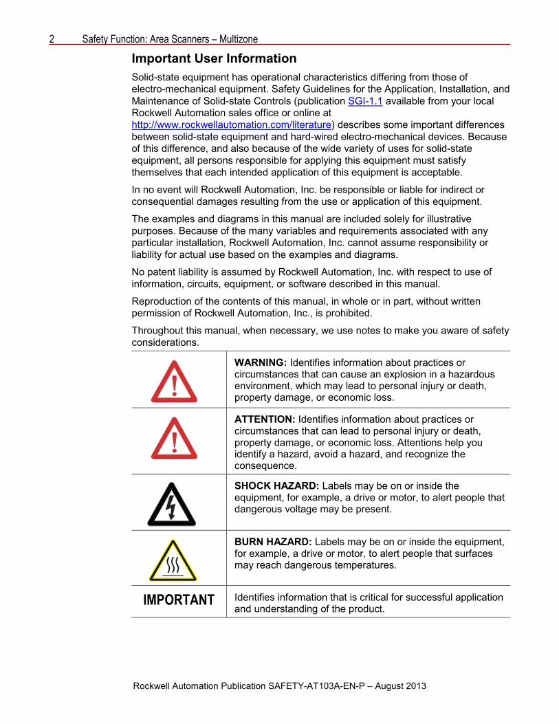
Throughout this manual, when necessary, we use notes to make you aware of safety considerations.
WARNING: Identifies information about practices or circumstances that can cause an explosion in a hazardous environment, which may lead to personal injury or death, property damage, or economic loss.
ATTENTION: Identifies information about practices or circumstances that can lead to personal injury or death, property damage, or economic loss. Attentions help you identify a hazard, avoid a hazard, and recognize the consequence.
SHOCK HAZARD: Labels may be on or inside the equipment, for example, a drive or motor, to alert people that dangerous voltage may be present.
BURN HAZARD: Labels may be on or inside the equipment, for example, a drive or motor, to alert people that surfaces may reach dangerous temperatures.
IMPORTANT Identifies information that is critical for successful application and understanding of the product.

Safety Function: Area Scanners – Multizone 3
Rockwell Automation Publication SAFETY-AT103A-EN-P – August 2013
General Safety Information Contact Rockwell Automation to find out more about our safety risk-assessment services.
IMPORTANT This application example is for advanced users and assumes that you are trained and experienced in safety system requirements.
ATTENTION: Perform a risk assessment to make sure all task and hazard combinations have been identified and addressed. The risk assessment can require additional circuitry to reduce the risk to a tolerable level. Safety circuits must take into consideration safety distance calculations, which are not part of the scope of this document.
Table of Contents Introduction ............................................................................................................... 3
Safety Function Realization: Risk Assessment ......................................................... 4
Multizone Laser Scanner Safety Function ................................................................. 4
Safety Function Requirements .................................................................................. 4
Functional Safety Description ................................................................................... 5
Bill of Material ........................................................................................................... 5
Setup and Wiring ...................................................................................................... 6
Configuration ............................................................................................................ 8
Calculation of the Performance Level ...................................................................... 15
Verification and Validation Plan ............................................................................... 19
Additional Resources .............................................................................................. 24
Introduction This safety function application technique explains how to wire and configure a Guardmaster™ dual-input safety relay (GSR DI) to monitor both an E-stop and multizone safety laser scanner. When an object intrudes into the SafeZone™ laser-scanner sensing field, when the E-stop is actuated or when a fault is detected in the monitoring circuit, the relay de-energizes the final control devices, a pair of 100S safety contactors. The multizone safety scanner can be used in either vertical or horizontal applications to detect the intrusion of personnel or objects into the sensing field. Configuration of the safety scanner’s warning and safety fields is accomplished using the Safety Configuration and Diagnostics (SCD) software supplied with each scanner.

4 Safety Function: Area Scanners – Multizone
Rockwell Automation Publication SAFETY-AT103A-EN-P – August 2013
Safety Function Realization: Risk Assessment The performance level required is the result of a risk assessment and refers to the amount of the risk reduction to be carried out by the safety-related parts of the control system. Part of the risk reduction process is to determine the safety functions of the machine. For the purposes of this document, the assumed required performance level (PLr) for each safety function is Performance Level d, Category 3 (PLd, Cat. 3). A safety system that achieves PLd, Cat. 3, or higher, can be considered control reliable.
Multizone Laser Scanner Safety Function The safety system described in this application has two safety functions:
• Emergency stop initiated by presence in the protective area of the multizone safety scanner.
• Emergency stop initiated by actuation of an emergency push button.
Safety Function Requirements Interrupting the configured sensing zone of the SafeZone multizone laser scanner stops and prevents hazardous motion by removing power to the motor. The motor coasts to a stop (Stop Category 0). When the scanner is reset, hazardous motion and power to the motor do not resume until a secondary action occurs—the Start button depressed. A fault at the laser scanner is detected before the next safety demand. With the laser scanner, you can monitor multiple zones by using suitable inputs. The safe distance from the location of the laser scanner to the hazard must be established, per EN ISO 13855, such that hazardous motion must be stopped before the user can reach the hazard.
Pressing the E-stop button stops hazardous motion by removing power to the motor. Releasing the E-stop does not restart hazardous motion. Pressing the Reset button after the E-stop has been reset and all faults are cleared, results in the restoration of hazardous motion.
From: Risk Assessment (ISO 12100)
1. Identification of safety functions
2. Specification of characteristics of each function
3. Determination of required PL (PLr) for each safety function
To: Realization and PL Evaluation

Safety Function: Area Scanners – Multizone 5
Rockwell Automation Publication SAFETY-AT103A-EN-P – August 2013
The safety function meets the requirements of Performance Level d, Category 3 (PLd, Cat. 3) per EN ISO 13849-1 and control reliable operation per ANSI B11.19.
Functional Safety Description Hazardous motion is stopped or prevented by interrupting the sensing field of the SafeZone laser scanner. The laser scanner can be programmed for up to four zones that can be selected using the two-position key selector switch. The 442L laser scanner and the E-stop are connected to the Guardmaster dual-input safety relay (GSR DI). The relay provides two N.O. safety contacts which control power to the 100S contactor coils. Whenever the relay opens the safety contacts, the hazardous motion is stopped. When all safety input signals are correct, no faults are detected, and the Reset button is pressed and released, the relay energizes its safety contacts providing power to the contactor coils. The E-stop is connected to the relay, which uses pulse-checking to monitor the E-stop for actuation and faults. Whenever the E-stop is actuated, the relay opens its safety contacts and the hazardous motion is stopped. When all safety input signals are correct, no faults are detected, and the Reset button is pressed (for 0.25…3.0 seconds), then released, the relay re-energizes its safety contacts providing power to the contactor coils.
In summary, when the laser scanner is blocked, or the E-stop is actuated, the contactors drop out. When the laser scanner is unblocked, the E-stop is released and the Reset button is pressed and released, the contactors are energized.
Bill of Material This application uses these products.
Cat. No. Description Quantity 442L-SFZNMZ SafeZone multizone scan head and I/O module 1
442L-CSFZNMZ-10 10M pre-wired 13-conductor memory module 1
442L-ACRS232 2M RS-232 configuration cable 1
800F-1YP8 800F 1-hole enclosure E-stop station, plastic, PG, twist-to-release 60mm, non-illuminated, 1 N.O. contact, 2 N.C. contacts
1
440R-D22R2 Guardmaster dual-input safety relay, 2 dual-channel universal inputs, 1 N.C. contact solid-state auxiliary output
1
800FM-KM23MX12
800F 2-position key selector switch - metal, maintained, all key removal, key code 3825 (standard), 1 N.O. contacts, 2 N.C. contact blocks, standard pack (quantity 1)
1
800FM-G611MX10 800F push button - metal, guarded, blue, R, metal latch mount, 1 N.O. contact, 0 N.C. contact, standard 1
100S-C09EJ23BC Modular control system (MCS) 100S-C safety contactor, 9 A, 24V DC (with electrical coil), bifurcated contact 2

6 Safety Function: Area Scanners – Multizone
Rockwell Automation Publication SAFETY-AT103A-EN-P – August 2013
Setup and Wiring For detailed information on installing and wiring, refer to the publications listed in the Additional Resources on the back cover.
System Overview The Guardmaster dual-input safety relay (GSR DI) monitors the input from the SafeZone multizone safety laser scanner control and the E-stop. The laser scanner control provides two PNP outputs that are de-energized when an object interrupts the field of view.
When an intrusion in the SafeZone sensing area is detected, a pair of 100S safety contactors, K1 and K2, are de-energized. The contactors are controlled by the relay. These are wired in a redundant configuration and are tested on startup for faults. These de-energized contactors remove power to the motor and the motor coasts to a stop (Stop Category 0). When the laser scanner control returns to the non-interrupted state, the contactors in the output do not energize until the system is reset by a momentary push button.
The relay also monitors the E-stop circuit for faults. Open circuit faults, shorts to 24V DC, shorts to GND, contact-weld faults, and cross-channel faults are detected. When a fault is detected or when the E-stop is actuated, the safety relay responds by de-energizing the 100S contactor coils, removing power to the motor. The motor coasts to a stop (Stop Category 0).
Two N.C. contacts, one from each of the safety contactors, are connected as part of the reset circuit. The safety relay can be reset only if both safety contactors are in a proper de-energized state.
The system is to be designed such that no single fault results in the safety system failing to perform its safety function. A single fault is detected before the next demand on the safety system. The system cannot be reset until the fault is corrected.
Installation A SafeZone laser scanner provides no physical barrier between a person and the hazardous motion. The protective field of the SafeZone laser scanner must extend a sufficient distance from the hazardous motion to make sure that anyone entering into the configured sensing zone cannot reach the hazard before it has stopped. This distance is referred to as the safety distance.
The safety distance (S) required varies from installation to installation and, therefore, must be calculated for each specific application. This application technique uses the formulas from EN ISO 13855.
Safety Function: Area Scanners – Multizone 7
Rockwell Automation Publication SAFETY-AT103A-EN-P – August 2013
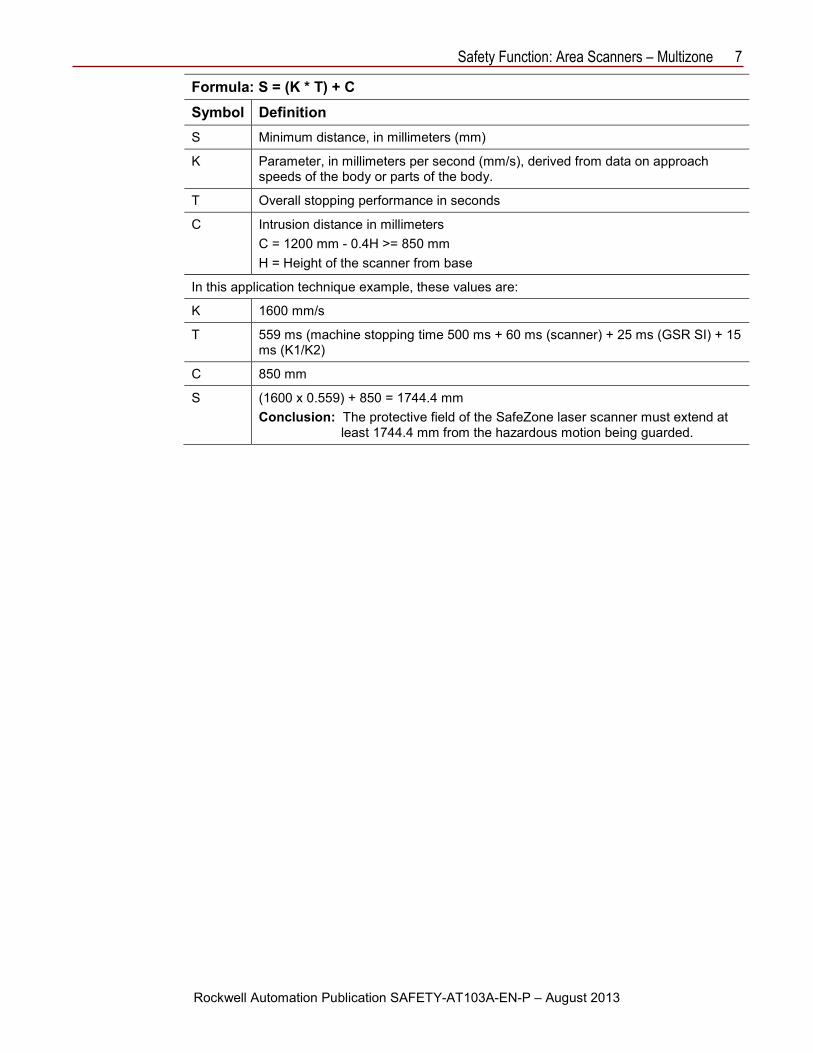
Formula: S = (K * T) + C Symbol Definition S Minimum distance, in millimeters (mm)
K Parameter, in millimeters per second (mm/s), derived from data on approach speeds of the body or parts of the body.
T Overall stopping performance in seconds
C Intrusion distance in millimeters C = 1200 mm - 0.4H >= 850 mm H = Height of the scanner from base
In this application technique example, these values are:
K 1600 mm/s
T 559 ms (machine stopping time 500 ms + 60 ms (scanner) + 25 ms (GSR SI) + 15 ms (K1/K2)
C 850 mm
S (1600 x 0.559) + 850 = 1744.4 mm Conclusion: The protective field of the SafeZone laser scanner must extend at
least 1744.4 mm from the hazardous motion being guarded.
8 Safety Function: Area Scanners – Multizone
Rockwell Automation Publication SAFETY-AT103A-EN-P – August 2013
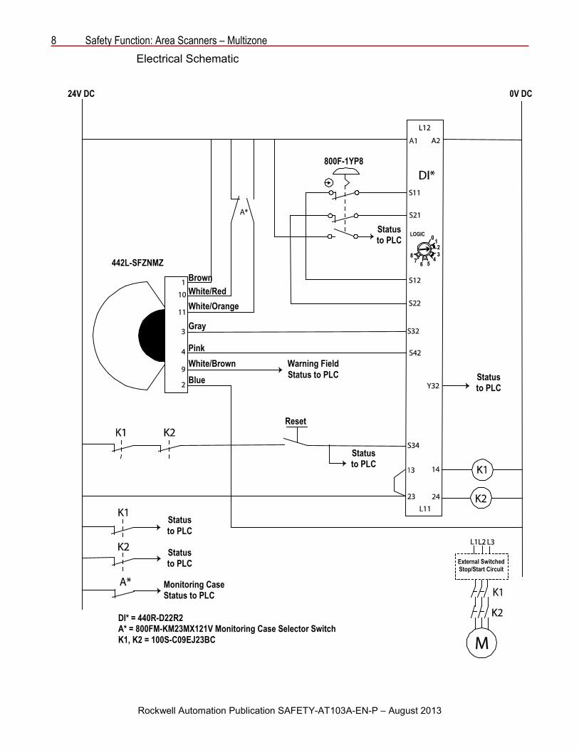
Electrical Schematic
24V DC 0V DC
800F-1YP8
442L-SFZNMZ
Status to PLC
Status to PLC
Status to PLC
Status to PLC
Status to PLC
Warning Field Status to PLC
Monitoring Case Status to PLC
DI* = 440R-D22R2 A* = 800FM-KM23MX121V Monitoring Case Selector Switch K1, K2 = 100S-C09EJ23BC
Reset
External Switched Stop/Start Circuit
Brown White/Red White/Orange
Gray
Pink White/Brown Blue
LOGIC
Safety Function: Area Scanners – Multizone 9
Rockwell Automation Publication SAFETY-AT103A-EN-P – August 2013
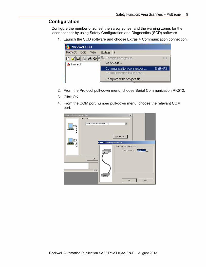
Configuration Configure the number of zones, the safety zones, and the warning zones for the laser scanner by using Safety Configuration and Diagnostics (SCD) software.
1. Launch the SCD software and choose Extras > Communication connection.
2. From the Protocol pull-down menu, choose Serial Communication RK512.
3. Click OK.
4. From the COM port number pull-down menu, choose the relevant COM port.
10 Safety Function: Area Scanners – Multizone
Rockwell Automation Publication SAFETY-AT103A-EN-P – August 2013
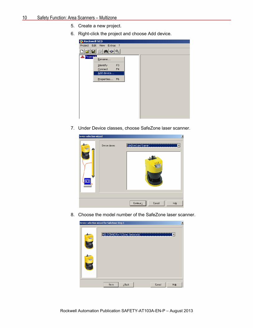
5. Create a new project.
6. Right-click the project and choose Add device.
7. Under Device classes, choose SafeZone laser scanner.
8. Choose the model number of the SafeZone laser scanner.

Safety Function: Area Scanners – Multizone 11
Rockwell Automation Publication SAFETY-AT103A-EN-P – August 2013
9. Right-click SafeZone systems and choose Configuration draft > Edit.
10. Type the Application name and the Scanner name 1 and click Continue.
11. Under Application, click Stationary and then click Continue.

12 Safety Function: Area Scanners – Multizone
Rockwell Automation Publication SAFETY-AT103A-EN-P – August 2013
12. Under Resolution, click 150 mm (body detection) and click Continue.
13. Verify that External device monitoring active is unchecked and click Continue.
14. In the dialog box, do the following:
a. Under Control inputs, check A.
b. Under Sampling for the static control inputs, click 1 of n.
c. Under Input delay [ms], choose 100…300.

Safety Function: Area Scanners – Multizone 13
Rockwell Automation Publication SAFETY-AT103A-EN-P – August 2013
15. Under Restart, click Without restart interlock and click Continue.
16. Create the Field set name.
The following shows the parameters of the two configurations.
14 Safety Function: Area Scanners – Multizone
Rockwell Automation Publication SAFETY-AT103A-EN-P – August 2013
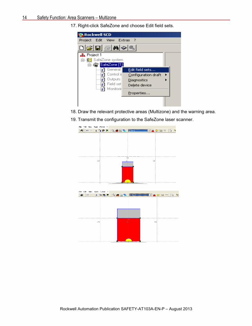
17. Right-click SafeZone and choose Edit field sets.
18. Draw the relevant protective areas (Multizone) and the warning area.
19. Transmit the configuration to the SafeZone laser scanner.

Safety Function: Area Scanners – Multizone 15
Rockwell Automation Publication SAFETY-AT103A-EN-P – August 2013
The relay must be configured LOGIC 2, (L12) or (IN 1 and IN 2). Refer to the installation instructions.
Calculation of the Performance Level This SISTEMA Software Performance Level (PL) Calculation Tool project includes two safety functions:
• Emergency stop of hazardous motion initiated by a SafeZone multizone safety laser scanner
• Emergency stop initiated by the actuation of the E-stop
The achieved Performance Level values for the individual safety functions are shown below.
The Performance Level achieved by each safety function is either equal to or higher than the Performance Level required (PLd per EN ISO 13849-1: 2008) by the risk assessment.
Electro-mechanical devices, like E-stop buttons and safety contactors, have limited operational lives directly related to how often they are operated. In the following calculations, it is presumed that the E-stop button is operated twice daily, for a total of 730 times a year. The contactors, whose operation can be the result of powerup or reset, an E-stop being pressed, or the sensing field of the single-zone scanner being interrupted, are presumed to be operated a total of 8760 times a year.
LOGIC

16 Safety Function: Area Scanners – Multizone
Rockwell Automation Publication SAFETY-AT103A-EN-P – August 2013
Functional safety data for emergency stop of hazardous motion initiated by a single-zone safety scanner
Functional safety data for the safety scanner subsystem
Functional safety data for the Guardmaster dual-input safety relay (GSR DI) subsystem
INPUT LOGIC OUTPUT
Multizone Safety
Scanner
Subsystem 1 Subsystem 3
100S K1 Contactor
100S K2 Contactor
Subsystem 2
GSR DI

Safety Function: Area Scanners – Multizone 17
Rockwell Automation Publication SAFETY-AT103A-EN-P – August 2013
Functional safety data of the output actuator
Functional safety data for emergency stop of hazardous motion initiated by an E-stop with N.C.
Functional safety data for the Guardmaster dual-input safety relay
Subsystem 1
INPUT AND ACTUATION LOGIC
Subsystem 2
E-Stop 1 NC
100S K2
100S K1
E-Stop 1 NC
GSR DI Safety Relay

18 Safety Function: Area Scanners – Multizone
Rockwell Automation Publication SAFETY-AT103A-EN-P – August 2013
Functional safety data for the input and output actuation subsystem
Because these are electro-mechanical devices, the E-stop and safety contactors data includes the following:
• Mean Time to Failure, dangerous (MTTFd)
• Diagnostic Coverage (DCavg)
• Common Cause Failure (CCF)
Electro-mechanical devices functional safety evaluations include the following:
• How frequently they are operated
• Whether they are effectively monitored for faults
• Whether they are properly specified and installed
SISTEMA calculates the MTTFd by using B10d data provided for the contactors along with the estimated frequency of use, entered during the creation of the SISTEMA project.
The DCavg (99%) for the contactors is selected from the Output Device table of EN ISO 13849-1 Annex E, Direct Monitoring.
The DCavg (99%) for the E-stop is selected from the Input Device table of EN ISO 13849-1 Annex E, Cross Monitoring.
The CCF value is generated by using the scoring process outlined in Annex F of EN ISO 13849-1. The complete CCF scoring process must be performed when actually implementing an application. A minimum score of 65 points must be achieved.

Safety Function: Area Scanners – Multizone 19
Rockwell Automation Publication SAFETY-AT103A-EN-P – August 2013
Verification and Validation Plan Verification and validation play important roles in the avoidance of faults throughout the safety system design and development process. EN ISO 13849-2 sets the requirements for verification and validation. The standard calls for a documented plan to confirm all of the safety functional requirements have been met.
Verification is an analysis of the resulting safety control system. The Performance Level (PL) of the safety control system is calculated to confirm that the system meets the required Performance Level (PLr) specified. The SISTEMA software is typically used to perform the calculations and assist with satisfying the requirements of EN ISO 13849-1.
Validation is a functional test of the safety control system to demonstrate that the system meets the specified requirements of the safety function. The safety control system is tested to confirm that all of the safety-related outputs respond appropriately to their corresponding safety-related inputs. The functional test includes normal operating conditions in addition to potential fault inject of failure modes. A checklist is typically used to document the validation of the safety control system.
Prior to validating the Guardmaster safety relay (GSR) system, confirm that the Guardmaster safety relay has been wired and configured in accordance with the installation instructions.

20 Safety Function: Area Scanners – Multizone
Rockwell Automation Publication SAFETY-AT103A-EN-P – August 2013
GSR SafeZone Laser Scanner Safety Function General Machine
Machine Name/Model Number Customer Name Test Date Tester Name(s) Schematic Drawing Number Guardmaster Safety Relay Model
Safety Wiring and Relay Configuration Verification Test Step Verification Pass/Fail Changes/Modifications
Visually inspect the safety relay circuit to verify that it is wired as documented in the schematics.
Visually inspect the SafeZone laser scanner to verify that it is wired as documented.
Visually inspect the safety-relay rotary switch settings to verify that they are correct as documented.
Normal Operation Verification The safety relay system properly responds to all normal Start, Stop, E-stop, and Reset
commands. Test Step Verification Pass/Fail Changes/Modifications
Initiate a Start command. Both contactors energize for a normal machine run condition. Verify proper machine-status indication and safety-relay status indication.
Initiate a Stop command. Both contactors de-energize for a normal machine Stop condition. Verify proper machine-status indication and safety-relay status indication.
While the system is running, interrupt the SafeZone laser scanner. Both contactors de-energize and open for a normal safe condition. Verify proper machine-status indication and safety-relay status indication.
While the system is stopped, interrupt the SafeZone laser scanner and initiate a Start command. Both contactors remain de-energized and open for a normal safe condition. Verify proper machine-status indication and safety-relay status indication.
Initiate a Reset command. Both contactors remain de-energized. Verify proper machine-status indication and safety-relay status indication.

Safety Function: Area Scanners – Multizone 21
Rockwell Automation Publication SAFETY-AT103A-EN-P – August 2013
GSR SafeZone Laser Scanner Safety Function (continued) Abnormal Operation Verification
The safety relay system properly responds to all foreseeable faults with corresponding diagnostics.
SafeZone Laser Scanner Test Step Validation Pass/Fail Changes/Modifications
While the system is running, remove the channel 1 wire from the safety relay. Both contactors de-energize. Verify proper machine-status indication and safety-relay status indication. Repeat for channel 2.
While the system is running, short channel 1 of the safety relay to 24V DC. Both contactors de-energize. Verify proper machine-status indication and safety-relay status indication. Repeat for channel 2.
While the system is running, short channel 1 of the safety relay to 0V DC. Both contactors de-energize. Verify proper machine-status indication and safety-relay status indication. Repeat for channel 2.
While the system is running, short channels 1 and 2 of the safety relay. Both contactors de-energize. Verify proper machine-status indication and safety-relay status indication.
GSR Logic Solver Tests Test Step Validation Pass/Fail Changes/Modifications
While the system is running, remove the single wire safety connection between two adjoining safety relays in the system. All contactors de-energize. Verify proper machine-status indication and safety-relay status indication. Repeat for all safety connects. The test is not applicable for single replay circuits.
While the system is running, turn the logic rotary switch on the safety relay. All contactors remain energized. Verify proper machine-status indication and safety-relay status indication. Repeat for all safety relays in the system.
Safety Contactor Output Tests Test Step Validation Pass/Fail Changes/Modifications
While the system is running, remove the contactor feedback from the safety relay. All contactors remain energized. Initiate a Stop command followed by a Reset command. The relay does not restart or reset. Verify proper machine-status indication and safety-relay status indication.

22 Safety Function: Area Scanners – Multizone
Rockwell Automation Publication SAFETY-AT103A-EN-P – August 2013
GSR SafeZone Laser Scanner Safety Function (continued) General Machine
Machine Name/Model Number Customer Name Test Date Tester Name(s) Schematic Drawing Number Guardmaster Safety Relay Model
Safety Wiring and Relay Configuration Verification Test Step Verification Pass/Fail Changes/Modifications
Visually inspect the safety relay circuit to verify that it is wired as documented in the schematics.
Visually inspect the SafeZone laser scanner to verify that it is wired as documented.
Visually inspect the safety-relay rotary switch settings to verify that they are correct as documented.
Normal Operation Verification The safety relay system properly responds to all normal Start, Stop, E-stop, and Reset
commands. Test Step Verification Pass/Fail Changes/Modifications
Initiate a Start command. Both contactors energize for a normal machine run condition. Verify proper machine-status indication and safety-relay status indication.
Initiate a Stop command. Both contactors de-energize for a normal machine Stop condition. Verify proper machine-status indication and safety-relay status indication.
While the system is running, interrupt the SafeZone laser scanner. Both contactors de-energize and open for a normal safe condition. Verify proper machine-status indication and safety-relay status indication.
While the system is stopped, interrupt the SafeZone laser scanner and initiate a Start command. Both contactors remain de-energized and open for a normal safe condition. Verify proper machine-status indication and safety-relay status indication.
Initiate a Reset command. Both contactors remain de-energized. Verify proper machine-status indication and safety-relay status indication.

Safety Function: Area Scanners – Multizone 23
Rockwell Automation Publication SAFETY-AT103A-EN-P – August 2013
GSR SafeZone Laser Scanner Safety Function (continued) Abnormal Operation Verification
The safety relay system properly responds to all foreseeable faults with corresponding diagnostics.
E-stop Input Tests Test Step Validation Pass/Fail Changes/Modifications
While the system is running, remove the channel 1 wire from the safety relay. Both contactors de-energize. Verify proper machine-status indication and safety-relay status indication. Repeat for channel 2.
While the system is running, short channel 1 of the safety relay to 24V DC. Both contactors de-energize. Verify proper machine-status indication and safety-relay status indication. Repeat for channel 2.
While the system is running, short channel 1 of the safety relay to 0V DC. Both contactors de-energize. Verify proper machine-status indication and safety-relay status indication. Repeat for channel 2.
While the system is running, short channels 1 and 2 of the safety relay. Both contactors de-energize. Verify proper machine-status indication and safety-relay status indication.
GSR Logic Solver Tests Test Step Validation Pass/Fail Changes/Modifications
While the system is running, remove the single-wire safety connection between two adjoining safety relays in the system. All contactors de-energize. Verify proper machine-status indication and safety-relay status indication. Repeat for all safety connects. The test is not applicable for single replay circuits.
While the system is running, turn the logic rotary switch on the safety relay. All contactors remain energized. Verify proper machine-status indication and safety-relay status indication. Repeat for all safety relays in the system.
Safety Contactor Output Tests Test Step Validation Pass/Fail Changes/Modifications
While the system is running, remove the contactor feedback from the safety relay. All contactors remain energized. Initiate a Stop command followed by a Reset command. The relay does not restart or reset. Verify proper machine-status indication and safety-relay status indication.

24 Safety Function: Area Scanners – Multizone
For more information on Safety Function Capabilities, visit: discover.rockwellautomation.com/safety Rockwell Automation, Allen-Bradley, Rockwell Software, Guardmaster, SafeZone, and LISTEN.THINK.SOLVE. are trademarks of Rockwell Automation, Inc. Trademarks not belonging to Rockwell Automation are property of their respective companies. Publication SAFETY-AT103A-EN-P – August 2013 Copyright © 2013 Rockwell Automation, Inc. All rights reserved. Printed in U.SA.
Additional Resources Refer to these publications for more information about related products from Rockwell Automation.
Resource Description GuardMaster Safety Relay DI Installation Instruction, publication 10000175129 ver. 00
Provides information on installing, operating, and maintaining safety relays.
Guardmaster Safety Relays Application and Wiring Diagrams, publication SAFETY-WD001
Provides functional descriptions, guidance, and wiring for typical safety relay.
Safety Product Catalog, publication S117-CA001
Provide data and guidance concerning safety principals, standards component data, and application examples.
You can view or download publications at http://www.rockwellautomation.com/literature. To order paper copies of technical documentation, contact your local Allen-Bradley distributor or Rockwell Automation sales representative.