Safety, Excellence & Quality with Integrity
30
Safety, Excellence & Quality with Integrity PRODUCT CATALOGUE www.gradwelloilfield.com Liner Hanger System | Packer System | Bridge Plugs | Floating Equipment | Centralizers [email protected] Manufacture, Supply & Services of Oilfield Drilling, Cementing & Completion Equipment
Transcript of Safety, Excellence & Quality with Integrity

Safety, Excellence & Quality with Integrity
PRODUCT CATALOGUE
www.gradwelloilfield.com
Liner Hanger System | Packer System | Bridge Plugs | Floating Equipment | Centralizers
Manufacture, Supply & Services of Oilfield Drilling,
Cementing & Completion Equipment

LIN
ER
HA
NG
ER
SY
ST
EM
& R
UN
NIN
G T
OO
LS
➢ HYDRAULIC ROTATING LINER HANGER (GR-RHLH)…………………………………….......................01
➢ HYDRAULIC SET DOUBLE CONE NON-ROTATING LINER HANGER (GR-NRHLH-2).......................03
➢ MECHANICAL SET DOUBLE CONE NON-ROTATING LINER HANGER (GR-MLHD)…....................05
➢ TIE BACK RECEPTACLE (GR-TBR)………………………………………………...…….............................07
➢ SETTING COLLAR (GR-SC-HR)…………….……………………………………….…….............................07
➢ LANDING COLLAR (GR-LCL-BC)……………………………………………………….............................. 07
➢ HYDRAULIC LATCH LANDING COLLAR (GR-LHA)..............................................................................08
➢ CONVENTIONAL SINGLE VALVE FLOAT COLLAR ( GR-CFC-1)........................................................08
➢ DOUBLE VALVE FLOAT SHOE WITH DOWN JET PORTS (GR-DJFS-2)............................................09
➢ HANDLING NIPPLE (GR-HN)....................................................................................................................09
➢ DEBRIS JUNK SCREEN (GR-DSC)..........................................................................................................09
➢ HYDRAULIC RELEASE RUNNING TOOL (GR-HRT)..............................................................................10
➢ SETTING TOOL ROTATING FOR LINER HANGER (GR-STLH)…………………...................................10
➢ MECHANICAL RELEASE RUNNING TOOL (GR-RTRM)........................................................................11
➢ PACKER SETTING TOOL (GR-RPST)..................................................................................................... 11
➢ RETRIEVABLE PACK OFF BUSHING (GR-RPOB).................................................................................12
➢ DRILLABLE PACK OFF BUSHING SUB (GR-DPOB).............................................................................12
➢ SLICK JOINT (GR-SJ)…………………………………………………………………...…..............................13
➢ TIE BACK SEAL NIPPLE (GR-TSN).........................................................................................................13
➢ DRILL WIPER PLUG (DWP).……............................................................................................................ 14
➢ LINER WIPER PLUG (LWP)…………………………………………………………….…..............................14
➢ LINER TOP PACKER (GR-LTP-IS)………………………………………………….…….............................15
➢ TIE BACK SEAL NIPPLE PACKER (GR-TSNP-IS)..…………………………………….............................17
➢ SWAB CUP ASSEMBLY(GR-SWAB)……………………..……………………………….............................18
➢ LINER SWIVEL SUB (GR-LSS)………………………………………………………….................................18
➢ TOP DRESS MILL (GR-TDM)………………………………………………………...……..............................19
➢ CLEAN OUT BLADE MILL (GR-CBM)......................................................................................................19
➢ HYDRAULIC STAGE CEMENTING TOOL(GR-HSC)...............................................................................20
➢ MECHANICAL STAGE CEMENTING TOOL (GR-MSC)..........................................................................21
➢ TWO STAGE THREE PLUG CEMENTING................................................................................................22
➢ TWO STAGE FOUR PLUG CEMENTING..................................................................................................22
➢ BAFFLE COLLAR......................................................................................................................................23
➢ BAFFLE PLATE............................................................................................………………………………..23
➢ CEMENTING HEAD......................................................................................……………………………….24
➢ TOP DRIVE CEMENTING HEAD...............................................................................................................25
➢ HOOK – UP : HYDRAULIC NON-ROTATING WITH LINER HANGER W / LINER TOP….....................26
TABLE OF CONTENT

87
HYDRAULIC ROTATING LINER HANGER
MODEL: GR-RHLH
Hydraulic Liner Hanger is used to hang a
liner in the well. It is set hydraulically by
applied pressure through the run-in string,
and is designed to support medium to heavy
liner loads. The hanger is widely used in
deep and high angle wells, where actuation
of mechanical-set hangers may not be
preferred. A setting ball is dropped and/or
circulated to a ball seat in the landing collar
or running string. Differential pressure acts
on the hydraulic cylinder, moving slips up to
the set position.
This LH has two types Multi cone pocket
slip type or Dovetail type with rotating or
non-Rotating mechanism. Multi cone
design provides excellent fluid bypass for
proper cementing. Hydraulic liner hanger
is couple with running tools, pack off
bushing, hydraulic landing collar, float
collar (if required), and float shoe and
other tools. In this document we include
dimensional details of liner hanger, parts
of liner hanger and operation of liner
hanger.
GR-RHLH
Features:
➢ No tubing manipulation required during
setting.
➢ Large multi slot design provides excellent
bypass area for proper cementing.
➢ Available in Single Cone, Double Cone,
and multi cone Dovetail type.
➢ Available in Non Rotating type design.
➢ High performance Roller bearing enables
rotation during running and Cementing for
proper cementing operation.
➢ Faster Running speed with Dovetail
design.
➢ Dovetail Slip cone Design delivers lower
and more uniform stresses on Casing and
mandrel enhance hanging capacity.
➢ Manufactured from a heavy walled
integral Tube which eliminates the no.
of internal connections and provide
maximum differential pressure rating
and liner hanging capacity.
➢ Case hardened Slips having
50-56 HRc hardness are suitable to
set inside all API casing grade.
➢ Protected type Slips are suitable for
highly deviated well operations.
➢ Available in all metallurgical con
forming to NACE MR 0175 or H2S,
and suitable for standard normal/
H2S, CO2 well services
requirements.
➢ Available in All API & Premium thread
connections and type.
➢ High Burst and collapse pressure
ratings.
Application :
➢ Offshore and Deviated Wells with tight
turns.
➢ High pressure and High temperature
wells.
➢ Well application requiring hanging
heavy liners.
➢ Drill down applications.
➢ Vertical and horizontal wells.
www.gradwelloilfield.com
LINER HANGER SYSTEM
01

88
LINER HANGER EQUIPMENT
Specification guide (GR- NRHLH-PS) :
** Threads shown above are standard for the respective Liner Hanger Mandrel sizes
other threads Can be supply on request when ordering.
Liner x Casing SizeCasing Weight
(lbs/ft)
Liner Hanger Max OD **Liner Thread
connection
4-1/2” x 7”
17-26 6.21”4-1/2”, 9.5-15.10#
casing thread29-38 5.680”
5” x 7”
23-26 6.050”5”, 11.5-24.1#
casing thread29-32 5.780”
35-38 5.680”
5-1/2” x 7”
17-26 4.781”5-1/2”, 14-23#
casing thread29-32 4.641”
5” x 7-5/8” 33.7 - 39 6.250”5”, 11.5-24.1#
casing thread
5-1/2” x 7-5/8”
24.0-29.70 6.620”5-1/2”, 14-23#
casing thread33.70-39 6.370”
7”x 9-5/8””
36-43.5 8.430”
7”, 17-35#
casing thread40-47 8.380”
47-53.5 8.250”
58.40 8.120”
7-5/8” x 9-5/8”
36-43.50 8.5”7-5/8”, 24-47.10#
casing thread47-53.50 8.310”
9-5/8” x 13-3/8” 54.50-68 12.009-5/8”, 32.30-58.40#
casing thread
www.gradwelloilfield.com
LINER HANGER SYSTEM
02

89
HYDRAULIC SET DOUBLE CONE NON-ROTATING LINER HANGER
MODEL: GR-NRHLH-2
Hydraulic Liner Hanger is used to hang a liner
in the well. It is set hydraulically by applied
pressure through the run-in string, and is
designed to support medium to heavy liner
loads. The hanger is widely used in deep and
high angle wells, where actuation of
mechanical-set hangers may not be preferred.
A setting ball is dropped and/or circulated to a
ball seat in the landing collar or running string.
Differential pressure acts on the hydraulic
cylinder, moving slips up to the set position.
This LH has two types single cone / double
cone type with rotating or non-Rotating
mechanism. Hydraulic liner hanger is
couple with running tools, pack off
bushing, hydraulic landing collar, float
collar (if required), and float shoe and
other tools. In this document we include
dimensional details of liner hanger, parts
of liner hanger and operation of liner
hanger.
GR-NRHLH-2
Features:
➢ No tubing manipulation required during
setting.
➢ Large bypass area for proper cementing.
➢ Available in Single Cone, Double Cone.
➢ Available in Rotating Non Rotating type
design.
➢ High performance Roller bearing enables
rotation during running and Cementing for
proper cementing operation.
➢ Manufactured from a heavy walled integral
Tube which eliminates the no. of internal
connections and provide maximum
differential pressure rating and liner
hanging capacity.
➢ Case hardened Slips having 50-56
HRc hardness are suitable to set inside
all API casing grade.
➢ Slips are protected with Split rings
suitable for highly deviated well
operations.
➢ Available in all metallurgical con
forming to NACE MR 0175 or H2S, and
suitable for standard normal/ H2S,
CO2 well services requirements.
➢ Available in All API & Premium thread
connections and type.
➢ High Burst and Collapse pressure
ratings.
Application:
➢ Offshore and Deviated Wells with right
turns.
➢ High pressure and High temperature
wells.
➢ Well application requiring hanging
heavy liners.
➢ Drill down applications.
➢ Vertical and horizontal wells.
www.gradwelloilfield.com
LINER HANGER SYSTEM
03

90
LINER HANGER EQUIPMENT
Specification guide (GR-NRHLH-2) :
** Threads shown above are standard for the respective Liner Hanger Mandrel sizes
other threads can be supply on request when ordering.
Liner x Casing SizeCasing Weight
(lbs/ft) Liner Hanger Max
OD
**Liner Thread
connection
4-1/2” x 7”17-26 6.21” 4-1/2”, 9.5-15.10#
casing thread29-38 5.680”
5” x 7”
23-26 6.050”5”, 11.5-24.1#
casing thread29-32 5.780”
35-38 5.680”
5-1/2” x 7”
17-26 4.781” 5-1/2”, 14-23#
casing thread29-32 4.641”
5” x 7-5/8” 33.7 - 39 6.250”5”, 11.5-24.1#
casing thread
5-1/2” x 7-5/8”
24.0-29.70 6.620”5-1/2”, 14-23#
casing thread33.70-39 6.370”
7”x 9-5/8””
36-43.5 8.430”
7”, 17-35#
casing thread40-47 8.380”
47-53.5 8.250”
58.40 8.120”
7-5/8” x 9-5/8”
36-43.50 8.5”7-5/8”, 24-47.10#
casing thread47-53.50 8.310”
9-5/8” x 13-3/8” 54.50-68 12.009-5/8”, 32.30-58.40#
casing thread
www.gradwelloilfield.com
LINER HANGER SYSTEM
04

91
MECHANICAL SET DOUBLE CONE NON-ROTATING LINER HANGER
MODEL: GR-MLHD
Gradwell Liner Hanger is set
mechanically with either right or left-
hand rotation, depending on the type
of setting tool or design. Staggered
cone design gives maximum bypass
area to ease running in and circulation.
Automatic J- cage allows hanger to re-
turn to the run-in position, should the
hanger set prematurely while running
in the well. The slip cage contains a “J”
slot and high strength drag springs to
manage the movement of the slips into
contact with the cones. Mechanical Set
Liner Hanger are set through
manipulation of the work string (pick-up & 1/4
right hand turn) line up the cones and the
slips, and a further slack off sets the slips
onto the casing wall.
This LH has two types Single cone / Double
cone type with rotating or non-Rotating
mechanism. Hydraulic liner hanger is couple
with running tools, pack off bushing, float
collar (if required), and float shoe and other
tools.
GR-MLHD
Features:
➢ Automatic J- cage, allows hanger to
return to run-in position constraining
hanger preset while running in.
➢ Open-bottom J-cage, available in
right or left-hand set.
➢ Large bypass area in run-in and set
position.
➢ Slips profile provide more biting
area to increase hanging capacity
and reduce the possibility of dam
age while running in.
➢ Single or multiple cone designs
available to match hanging capacity
with liner strength, minimizing
stress in supporting casing.
➢ Complete wells with less weight
landed on wellheads.
➢ Give rise to improved cementing
jobs.
➢ Prevent lost circulation.
➢ Provide good well control while
drilling and completing.
➢ Impart more completion flexibility.
➢ Afford low-cost liner on appraisal
wells.
➢ Liner Hangers are available with all
API and premium thread connections.
➢ Case hardened Slips having 50-
56 HRc hardness are suitable to set
inside all API casing grade.
➢ Slips are protected with Split rings
suitable for highly deviated well
operations.
➢ Available in all metallurgical con forming
to NACE MR 0175 or H2S, and suitable
for standard normal/ H2S, CO2 well
services requirements.
➢ Available in All API & Premium thread
connections and type.
➢ High Burst and Collapse pressure
ratings.
www.gradwelloilfield.com
LINER HANGER SYSTEM
05

92
LINER HANGER EQUIPMENT
Specification guide (GR-MLH-2) :
** Threads shown above are standard for the respective Liner Hanger Mandrel sizes
other threads can be supply on request when ordering.
Liner x Casing SizeCasing Weight
(lbs/ft)
Liner Hanger
Max OD**Liner Thread
connection
4-1/2” x 7”17-26 6.21” 4-1/2”, 9.5-15.10#
casing thread29-38 5.680”
5” x 7”
23-26 6.050”5”, 11.5-24.1#
casing thread29-32 5.780”
35-38 5.680”
5-1/2” x 7”
17-26 4.781” 5-1/2”, 14-23#
casing thread29-32 4.641”
5” x 7-5/8” 33.7 - 39 6.250”5”, 11.5-24.1#
casing thread
5-1/2” x 7-5/8”24.0-29.70 6.620”
5-1/2”, 14-23#
casing thread33.70-39 6.370”
7”x 9-5/8””
36-43.5 8.430”
7”, 17-35#
casing thread40-47 8.380”
47-53.5 8.250”
58.40 8.120”
7-5/8” x 9-5/8”
36-43.50 8.5”7-5/8”, 24-47.10#
casing thread47-53.50 8.310”
9-5/8” x 13-3/8” 54.50-68 12.009-5/8”, 32.30-58.40#
casing thread
www.gradwelloilfield.com
LINER HANGER SYSTEM
06

TIE BACK RECEPTACLE
MODEL: GR-TBR
The Polished Bore Receptacle (PBR) is
run as a part of the liner. This PBR comes
as a means to tie-back to and existing liner
with either a seal assemble or tie-back
packer for remedial work.
This PBR is a means to Tie-Back to the
liner system should it be needed. This
can be accomplished with a seal nipple
or with a Tie-Back packer
GR-TBRSETTING COLLAR
MODEL: GR-SC-HR
Setting Collar can be provided with HR
profile to run the spring with HRT Running
tool, Setting Collar having receptacle
profile for retrieval pack off bushing. The
model “SC” setting collar is used to carry
the liner into the well. It is used when using
a rotating liner hanger. The setting collar
has right hand releasing threads which are
made up with the threads of the setting
tool.
GR-SC-HR
The Setting Collar is made up on top of the
Liner Hanger and generally used when a
liner extension is not planned.
The fluted top guide assures centering of
the liner in the hole and its shape provides
an internal guide for smooth running of the
tools into the liner
LANDING COLLAR
MODEL: GR-LCL-BC
Landing Collar is used when setting liner
hanger prior to cementing. A setting ball
seat in the shear seat allowing pressure to
be applied to the hanger to set the slips.
Increasing the pressure after setting the
hanger shears the ball seat allowing full
circulation for cementing operations. The
shear rating of the ball seat is adjustable
to meet the requirements of the hanger. It
incorporates a latch with Non- rotational
Mechanism to accept, lock and seal the
Liner Wiper Plug upon completion of
cementing. Internal components are
manufacture from
➢ Brass shear pins loaded Ball seat.
➢ Suitable for H2S & CO2 service.
➢ High Burst and collapse pressure. GR-LCL-BC
PDC drillable Material and are
compatible for drill out. We retained ball
seat design prevents the sheared out
cage and ball assembly from interfering
with float equipment run below the
landing collar. Large, milled slots provide
an unrestricted flow area while
cementing. Shears/setting balls are
available in bronze, aluminum or phenolic
materials of varying specific gravity for
use in vertical, high angle or horizontal
wells or for specific cement weights. All
seals are of standard.
Features:
➢ Anti-rotation feature for wiper
plugs.
➢ Available in thread connection per
ordered.
➢ Available in all API material grades.
➢ PDC drillable material use for drill
out items.
www.gradwelloilfield.com
LINER HANGER SYSTEM
07

HYDRAULIC LATCH LANDING COLLAR
MODEL: GR-LHA
Gradwell Landing Collar provide a means to both set hydraulic tools and to catch a liner
wiper plug in a string of pipe.
Application :
When hydraulically actuated tools are
incorporated in the liner, Landing Collar is used
as a ball seat to facilitate the setting of these
tools. It is also used to catch and lock
(rotationally) the liner wiper plug.
A ball dropped from surface seats on
the ball seat in the Landing Collar and
allows the hydraulic tool to actuate
by applied pressure. The ball and
seat are then sheared and fall to a
Ball Catcher Sub.
CONVENTIONAL SINGLE VALVE FLOAT COLLAR
MODEL: GR-CFC-1
Float Collar is a cylindrical steel section with box
and pin threads. Float Collar generally uses one
string above the Float Shoe. It contains a check
valve to permit fluid to pass
downward but not upward through the
casing and provides a flat landing
surface for cementing plugs.
➢ Orifice float collar for Tie-back
application.
➢ Ball Catcher/Ball Deflector is avail
able upon request.
➢ Flat surface provides platform to
bump the bottom plug.
➢ Baffle plate float collar is available
upon request.
➢ Inner String float collar is available
for larger size casing.
GR-CFC-1
GR-LHA
Features:
➢ Fast Drill Out.
➢ Internal Parts are PDC drillable.
➢ Float Collar is available in all API grade
material.
➢ Float Collar can be furnished in API threads
as well as in Premium threads.
➢ Float Collar can be furnished with non
rotating feature.
➢ Valve is tested as per API RP 10F Category
III C.
➢ Maximum Back Pressure rating 5000 psi
@400°F.
➢ Tubing Float Collar for high pressure up to
10000 PSI.
Features:
➢ Ceramic Ball Seat - A ceramic insert has been
incorporated into the ball seat of most
standard sizes in order to eliminate erosion of
the critical sealing area during high rates of
circulation.
➢ Drillable - The inserts in these tools are made
of drillable cast aluminium for easy drill out,
and are compatible with all bit types including
PDC.
➢ Shear Pin Visibility - Shear pins can
be adjust after tool assembled.
➢ Thread Integrity Maintained – for
premium threads manufacturer’s
outside and inside diameters can be
maintained.
➢ Positive Latch - A latch thread in the
insert assures that the wiper plug will
not move after it has bumped.
www.gradwelloilfield.com
LINER HANGER SYSTEM
08

DOUBLE VALVE FLOAT SHOE WITH DOWN JET PORTS
MODEL: GR-DJFS-2
This design ensures positive sealing in vertical,
deviated & horizontal well. They have a back-
pressure valve that prevents fluids from
entering the casing while the pipe is lowered
into hole and prevents cement from flowing
back into the casing after displacement, while
enabling circulation down through casing.
Double Valve helps maximum protection
against back flow of cement.
GR-DJFS-2
There are three down-jet ports located
below float valve in side of the float shoe
shell to help to increase cement bonding
strength due to swirl effect by
cementing.
Sometimes, it provides landing point for
cementing plugs when Collar is not
used.
It is available with Down-jet, Up-jet &
Side-jet ports as well.
HANDLING NIPPLE
MODEL: GR-HN
The Handling Nipple is a heavy weight
Drill Pipe Pup Joint for handling the Liner
Hanger assembly and for using the Slips
and elevator once the assembly below
table. It is located above Packer Setting
Tool usually the Handling Nipple is
equipped with Junk Bonnet
GR-HN
DEBRIS JUNK SCREEN
MODEL: GR-DSC
The Junk Bonnet Sub consists of two metal cups installed around Lifting Sub with
two bolts.
The Liner Hanger junk screen should be run as part of the setting tool assembly to
prevent debris from damaging the polished bore of Tieback Receptacle.
GR-DSC
Features:
➢ Down-jet ports increase bonding strength
of cement.
➢ Provide passage of fluid with added
assurance that flow will not be interrupted
when casing rests at bottom.
Note: It is available in Single & Double Valve
design.
➢ Easy PDC drillable.
➢ Cost effective.
➢ Maximum protection against back
flow of cement.
Features:
➢ Available in all API drill pipe
thread connections.
➢ Available in different lengths from
10 feet to 20 feet
➢ Suitable for H2S & CO2 service
➢ Better Cementing wiping
www.gradwelloilfield.com
LINER HANGER SYSTEM
09

95
LINER HANGER EQUIPMENT
HYDRAULIC RELEASE RUNNING TOOL
MODEL: GR-HRT
Gradwell - HR Running Tool connects with the
HR Liner Setting sleeve and provides a means
to carry a Liner Down hole, set a Liner Hanger
and release from the liner prior to or, if desired
after cementing. The primary releasing
mechanism
is hydraulic with an emergency
mechanical back-up release system.
This tool carries the weight of the liner
on a fully supported collet assembly
with no threads that could back off and
drop the liner while running in the hole.
Application :
➢ Offshore and Deviated Wells with tight
turns.
➢ High pressure and High temperature wells.
➢ Well application requiring
hanging heavy liners.
➢ Vertical and horizontal wells.
Features :
➢ Push Pull and rotate while running the liner
down hole. The design of this tool allows
right hand rotation of the work string and
liner with the tool in tension, compression or
neutral.
➢ Rotation after release when running a
rotating liner hanger. Multiple torque fingers
permit rotation of the liner during cementing
after the hanger is set and the running tool
released from the liner.
➢ Easy stub-up to load the HR setting tool into
the HR liner Setting sleeve. Simply push
straight in and setting tool automatically
latches
➢ into the profile. Maximum 1/3 turn
engages the torque fingers.
➢ No Rotation to release after
actuating the hydraulic cylinder, the
tool is retrieved by straight pick-up.
The collet is retained in the
released position by an internal
body lock ring to prevent re-
engagement into the
setting sleeve profile.
➢ Emergency mechanical release
in the event the primary hydraulic
releasing mechanism fails to
operate, the setting tool may be
released mechanically by 1/4 turn
to left.
GR-HRT
SETTING TOOL ROTATING FOR LINER HANGER
MODEL: GR-STLH
The Model GR-STLH ,Setting Tool is used in
setting Rotating Liner Hanger. The Setting Tool is
provided with spring loaded Rotating Dog Sub
that mates with splines located in the setting
collar. This dog sub transfers torque from drill
string, to the liner, while in tension or
compression for
the purpose of setting Mechanical liner
Hanger, Rotating liner Hanger during
cementing operation, or insuring setting
tool engagement during run-in. the
model GR_STLH also utilizes the
retrievable Pack off bushing and seal
Joint.
GR-STLH
www.gradwelloilfield.com
LINER HANGER SYSTEM
10

MECHANICAL RELEASE RUNNING TOOL
MODEL: GR-RTRM
Mechanical release setting tool is a full
feature, mechanical release running
tool and packer setting assembly. With
no rotational drive capability, this
simply conveys the liner assembly and
then is released with right-hand
rotation after the hanger has been set.
Designed to release in compression,
this tool may be run in vertical, high-
angle or horizontal wells with a high
degree of confidence. The bearing
system facilitates both easy release of
the liner, and also aids in the setting of
weight set, liner top packer assemblies
by allowing the weight to be applied
under a rotational load, more evenly
distributing weight and ensuring that
maximum setting force reaches the
packer assembly.
As a service tool, the mechanical
release setting tool features heavy-duty
design and construction for a long,
usable service life. Standard
configuration is with API drill pipe box
for direct connection to a retrievable
seal joint, drillable seal joint, solid
bushing or inverted cup tool.
GR-RTRM
PACKER SETTING TOOL
MODEL: GR-RPST
The Gradwell - Packer setting tool is used
to set the Liner top Packer after setting
of Liner Hanger. Setting Dog
Section is spring loaded to set on top
of the Packer to allow setting force
to be transmitted to the Packer.
Features :
➢ High strength Spring loaded Dogs
Apply set down weight to set Liner Top
Packer.
➢ Available in all API material grades.
➢ Available in all API Drill
Pipe Threads.
➢ Suitable for H2S & CO2
service
GR-RPST
www.gradwelloilfield.com
LINER HANGER SYSTEM
11

98
LINER HANGER EQUIPMENT
RETRIEVABLE PACK OFF BUSHING
MODEL: GR-RPOB
DRILLABLE PACK OFF BUSHING SUB
MODEL: GR-DPOB
The Gradwell Retrievable Packoff
Bushing provides a positive seal
between the setting tool and the
liner, securely holding all cementing and
plugs bumping pressures. It features
temperature and pressures resistant
seals which are designed to hold
differential pressure from either
direction. It also reduces piston force on
the drill pipe during cementing
operations. After the completion of the
cementing, it is retrieved
Drillable Pack Off Bushing Sub Provide
the seal between stinger and Liner
Hanger body to set the liner Hanger.
with the setting tool, leaving the liner
top unrestricted. The Retrievable
Packoff Bushing with polished nipple is
installed in the setting collar and then
the setting tool can be made up. When
installed, the polished extension nipple
locks the retaining dogs into the RPOB
Profile. When the setting tool is
retrieved, a recessed/undercut section
on the bottom of the
Features:
Features:
➢ Eliminates reverse differential failures.
➢ Redressable in the field.
➢ Reduces the piston effect due to the small cross sectional area of the Polished
Nipple end.
➢ Provides a positive seal for high pressure and/or for high temperature.
➢ Available in thread connection on
order
➢ Available in all API material grades
➢ PDC drillable material use for drill
out items
➢ Suitable for H2S & CO2 service
➢ High Burst and collapse pressure
GR-RPOB
GR-DPOB
www.gradwelloilfield.com
LINER HANGER SYSTEM
12

SLICK JOINT
MODEL: GR-SJ
Seal stinger with grounded ODs is to provide
a sealing surface for the retrievable/drillable
Pack-off Bushing. These are manufactured
from higher group of API 5CT standard
materials as well as furnished with end
connections in compliance to API standard
and CRA materials suited for H2S or CO2
service are available on request.
A groove is provided at the bottom end
to attach the Liner Wiper Plug. Our seal
joint manufactured from high grade alloy
material and surface would be chrome
platted so as to possess resistance for
corrosive environments.
Features:
➢ Available in all API thread connections
➢ Available in different lengths from
10 feet to 20 feet
➢ Polished Bore high finished OD for
better sealing with Pack Of Bushing
Seals
➢ Suitable for H2S & CO2 service Better
Cementing wiping
GR-SJ
TIE BACK SEAL NIPLLE
MODEL: GR-TSN
The Tieback Seal Nipple with Chevron seal is
designed for high pressure liner tieback
completions. This honed bore, Tieback seal
nipple allows for future extension of the liner
casing string to surface for production, testing
or remedial operations during the life of the
well. This provides mono bore access to the
reservoir.
It may be used temporarily or permanently. To
facilitate both ease
of entry and cementing operations. It is
equipped with a standard mule guide
nose with circulations ports. Standard
seal configurations is four units in fabric
reinforced NBR with optional seals in
HNBR. Nipples are designed with ODs
compatible for Liner Tieback Packers and
Tieback Receptacles with varying in
lengths form 6 feet to 40 feet depending
on the applications.
Features :
➢ One-piece mandrel for high burst
and collapse properties.
➢ Glass filled chevron seals rated at
10,000 PSI at 400 F
➢ Available in lengths from 6 ft to 40 ft.
➢ Optional seal packages available for
severe well conditions.
➢ Available in all metallurgical con
forming to NACE MR 0175 or H2S,
and suitable for standard normal/
H2S, CO2 well services
requirements.
➢ Available in All API thread
connections and type.
➢ High Burst and Collapse pressure
ratings.GR-TSN
www.gradwelloilfield.com
LINER HANGER SYSTEM
13

100
LINER HANGER EQUIPMENT
DRILL WIPER PLUG
MODEL: GR-DWP
LINER WIPER PLUG
MODEL: GR-LWP
Gradwell inner-string Pump Down Plug is
pumped behind cement and wipes the
inside of drill pipe or tubing strings,
providing a mechanical barrier between
cement and spacer fluids or between
mud and cement.
It wipes cement from the drill pipe and
lands in Liner Wiper Plug. When this
happen the pressure increases and
shears the LWP. Allowing both plug to
The Liner Wiper Plug, commonly shear
pinned to the Liner setting Tool, has a
hollow internal diameter that allows fluids
and cement to pass through the plug until
the PDP latches into the Upper part of the
LWP.
be displaced as an unit to the Landing
Collar.
The “PDP” is designed for use with
Gradwell inner-string stab-in float
equipment to cement large-diameter
casing strings. The stinger dart is
launched from cementing head,
displacing fluids through the drill pipe
or tubing string while preventing
cement contamination.
The PDP is then mechanically and
hydraulically sealed to the LWP, and
the two plugs are sheared from the
Liner setting Tool. After wiping the
liner, the LWP is latched and sealed
to the landing collar preventing the
back flow of cement.
Features:
Application:
➢ Wiping drill pipe or tubing in
conjunction with Gradwell inner-string
float equipment.
➢ Composed entirely of PDC-
(polycrystalline diamond composite)
drillable materials, the stinger dart
enables trouble-free drill out, conserving
rig time.
➢ Seal ring provides a positive
bidirectional seal when latched into float
quipment with the corresponding
aluminum snap ring, enabling the
device to withstand exceptionally high
backpressures.
➢ PDP acts as a mechanical barrier
between displacement fluids to prevent
cement contamination, resulting in a
clean pipe ID.
➢ Angled, aluminum nose prevents
the dart from hanging up in the
drill pipe or tubing string,
ensuring proper functionality of
the device.
➢ Polyurethane fins offer superior
abrasion resistance and excellent
wiping action, resulting in a clean
casing ID after passage.
➢ Fin design enables versatility, sta
bility, and superior wiping action
for drill pipe and tubing strings,
providing operational flexibility.
➢ Large-diameter casing strings
requiring inner-string cementing
Features
GR-DWP
GR-LWP
www.gradwelloilfield.com
LINER HANGER SYSTEM
14
93
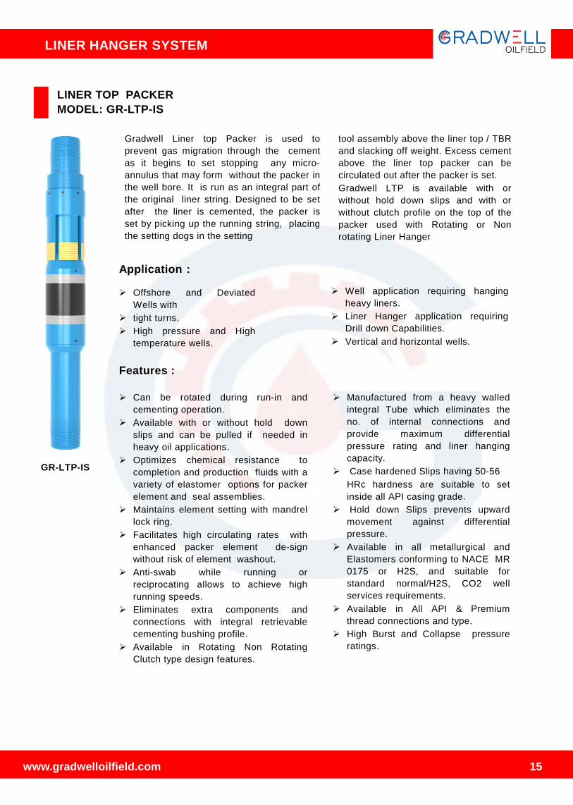
LINER TOP PACKER
MODEL: GR-LTP-IS
Gradwell Liner top Packer is used to
prevent gas migration through the cement
as it begins to set stopping any micro-
annulus that may form without the packer in
the well bore. It is run as an integral part of
the original liner string. Designed to be set
after the liner is cemented, the packer is
set by picking up the running string, placing
the setting dogs in the setting
tool assembly above the liner top / TBR
and slacking off weight. Excess cement
above the liner top packer can be
circulated out after the packer is set.
Gradwell LTP is available with or
without hold down slips and with or
without clutch profile on the top of the
packer used with Rotating or Non
rotating Liner Hanger
Features :
➢ Can be rotated during run-in and
cementing operation.
➢ Available with or without hold down
slips and can be pulled if needed in
heavy oil applications.
➢ Optimizes chemical resistance to
completion and production fluids with a
variety of elastomer options for packer
element and seal assemblies.
➢ Maintains element setting with mandrel
lock ring.
➢ Facilitates high circulating rates with
enhanced packer element de-sign
without risk of element washout.
➢ Anti-swab while running or
reciprocating allows to achieve high
running speeds.
➢ Eliminates extra components and
connections with integral retrievable
cementing bushing profile.
➢ Available in Rotating Non Rotating
Clutch type design features.
➢ Manufactured from a heavy walled
integral Tube which eliminates the
no. of internal connections and
provide maximum differential
pressure rating and liner hanging
capacity.
➢ Case hardened Slips having 50-56
HRc hardness are suitable to set
inside all API casing grade.
➢ Hold down Slips prevents upward
movement against differential
pressure.
➢ Available in all metallurgical and
Elastomers conforming to NACE MR
0175 or H2S, and suitable for
standard normal/H2S, CO2 well
services requirements.
➢ Available in All API & Premium
thread connections and type.
➢ High Burst and Collapse pressure
ratings.
Application :
➢ Offshore and Deviated
Wells with
➢ tight turns.
➢ High pressure and High
temperature wells.
➢ Well application requiring hanging
heavy liners.
➢ Liner Hanger application requiring
Drill down Capabilities.
➢ Vertical and horizontal wells.
GR-LTP-IS
www.gradwelloilfield.com
LINER HANGER SYSTEM
15

94
LINER HANGER EQUIPMENT
Specification guide ( GR-LTP-IS ) :
Liner x Casing
Size
Casing Weight
(lbs/ft)
Liner Hanger
Max OD
Liner Top
Packer Min ID*
**Liner Thread
connection
4-1/2” x 7”17-26 6.21”
3.8264-1/2”, 9.5-15.10#
casing thread29-38 5.680”
5” x 7”
23-26 6.050”
4(24.1ppf) 5”, 11.5-24.1#
casing thread29-32 5.780”
35-38 5.680”
5-1/2” x 7”17-26 4.781”
4.670(23ppf)5-1/2”, 14-23#
casing thread29-32 4.641”
5” x 7-5/8” 33.7 - 39 6.250” 4(24.1ppf)5”, 11.5-24.1#
casing thread
5-1/2” x 7-5/8”
24.0-29.70 6.620”
4.670(23ppf)5-1/2”, 14-23#
casing thread33.70-39 6.370”
7”x 9-5/8””
36-43.5 8.430”
6.276(26ppf)
6.184(29ppf)
7”, 17-35#
casing thread40-47 8.380”
47-53.5 8.250”
58.40 8.120”
7-5/8” x 9-5/8”
36-43.50 8.5” 6.875(29.7ppf)
6.375(47.10ppf)7-5/8”, 24-47.10#
casing thread47-53.50 8.310”
9-5/8” x 13-3/8” 54.50-68 12.00 (8.435ppf9-5/8”, 32.30-58.40#
casing thread
www.gradwelloilfield.com
LINER HANGER SYSTEM
16

LINER HANGER EQUIPMENT
TIE BACK SEAL NIPPLE PACKER
MODEL: GR-TSNP-IS
The Model “TSNP” is used mostly in vertical
well application. It can be used as Liner Top
isolation Packer in case of annulus leakage.
It commonly used when there is a leak in the
exiting packer or casing. It provides
secondary seal to prevent annular gas
migration and protect sensitive zones. It is a
weight set packer and packing elements are
locked in place by the internal ratchet The
mandrel of the tie back packer seals into the
polished bore receptacle of an existing liner
top packer or liner. The seal mandrel provides
a pressure competent sealing by engaging in
the tie back receptacle. There are different
seal material available for different well
conditions.
The Seal O.D is compatible with Tie
back Receptacle. It is provided with a
bottom mule shoe with circulation ports
for circulation and cementing if
required.
Features :
➢ To isolate the liner top after the
hanger is set and cementing
operations are completed
➢ Isolate formation pressure below the
liner top from the casing ID above
➢ Isolate treating pressures below the
liner-top during fracture or acid work
➢ It can be used as a tie-back
completion or production packer.
Packer Size
(Casing X
Packer)
(In.)
Casing Weight
(lbs/ft)
Packer
Max. OD
(In.)
5 3/4 X 4 18 4.940
7 X 4 35 5.819
7 X 4 1/2
23.0 -26.0 6.061
29.0 – 32.0 5.910
35.0 – 38.0 5.705
7 X 5
23.0 – 26..0 6.061
29.0 - 32.0 5.910
7 5/8 X 5 33.7 -39 6.440
9 5/8 X 7
40.0 – 47.0 8.435
47.0 – 53.5 8.312
53.5 - 58.4 8.188
9 5/8 X 7 5/8 53.5 8.334
10 3/4 X 7 55.5 – 60.7 9.445
10 3/4 X 7 5/8
45.1 – 51.0 9.625
55.5 - 60.7 9.438
65.7 – 73.2 9.160
79.2 – 86.36 8.937
11 3/4 X 9 5/8 60.0 – 65.0 10.375
13 3/8 X 9 5/8 61 -72 12.125
13 3/8 X 10 3/4
54 -61 12.300
61 - 72 12.130
16 X 13 3/8
75 – 84 14.700
84 - 109 14.375
Specification guide (GR-TSNP-IS) :
GR-TSNP-IS
www.gradwelloilfield.com
LINER HANGER SYSTEM
17

97
LINER SWIVEL SUB
MODEL: GR-LSS
The liner Swivel Sub is normally used when
running mechanical set liners in highly
deviated wells in which rotating to set the liner
may be a problem. The swivel allows rotation
of the hanger
➢ Available in all metallurgical con forming
to NACE MR 0175 or H2S, and suitable
for standard normal/ H2S, CO2 well
services requirements.
➢ Available in All API & Premium thread
connections and type.
➢ High Burst and Collapse pressure
ratings.GR-LSS
Features :
➢ The Liner Swivel allows rotation of the
anger without having to rotate the total
Liner.
➢ A clutch system in the swivel allows easy
release of the running nut from the liner, if
the liner has to be set on bottom.
SWAB CUP ASSEMBLY
MODEL: GR-SWAB
Gradwell Swab Cup Assembly Run
together with a hanger setting ball seat, the
swab cup pack off. Assembly allows for a
hanger to be set an Released Running Tool
without increasing the risk of formation
damage which occurs when pressuring the
entire liner for setting the hanger and
expending the setting ball. The ball seat in
the running tool string, in concert with the
swab cup packoff assembly, allows for
pressure to be maintained only in the work-
string, therefore decreasing surge on
the formation when the setting ball is
expended. The Ball Seat assembly consist
of Ball seat which is supported by Shear
Pins. The shear value of Seat sub is
always keep higher than the Setting
pressure of Liner hanger and releasing
pressure of Running Tool by changing the
No. of shear pins. After shearing of Ball
seat the Flo rate can be establish for
cementing or wash over operation.
Features:
➢ Available in NBR, HNBR, Viton
elastomers
➢ All Rubber cup designed for maximum
lifting capacity and extra-long life.
➢ Abrasion resistant
➢ High swabbing speeds, Deep wells, rough
tubing.
➢ Ball seat catcher hold the Ball seat and
Ball no need to left in well
➢ Setting Ball is available in Steel and
Brass material.
➢ Available in all metallurgical con
forming to NACE MR 0175 or H2S, and
suitable for standard normal/ H2S,
CO2 well services requirements.
➢ Available in All API thread connections
and type.
➢ High Burst and Collapse pressure
ratings.GR-SWAB
without rotating the total liner. A clutch
system in the swivel (feature may be
detected if required) allows easy re- lease
of running nut from the liner, if the liner has
to be set on bottom.
www.gradwelloilfield.com
LINER HANGER SYSTEM
18

TOP DRESS MILL
MODEL: GR-TDM
The Top Dress Mill has a tungsten carbide NO-go which dresses off
the TBR top very effectively. It has 4-1/2’’ regular Pin x Box
connections.
All parts are made of AISI 4140 ht high tensile material for heavy
duty.
The Polish / Dress Mill assembly is normally spaced out and made
up in the Gradwell Workshop
CLEAN OUT BLADE MILL
MODEL: GR-CBM
The Clean Out Mill assembly is used to clean the excess cement from
the tie back receptacle after the cement job is performed. This is to
prevent seal damage for and allow for good sealing of the seal stem
run in thereafter.
The POLISH Mill is designed with metal blade, which measure 1/16’’
less than the I.D of the TBR sleeve. It has an REG pin up and 2-7/8’’
REG 3-1/2’’ REG or 4-1/2’’ REG down depending on the size.
GR-TDM
GR-CBM
www.gradwelloilfield.com
LINER HANGER SYSTEM
19

89
HYDRAULIC STAGE CEMENTING TOOL
MODEL: GR-HSC
Features:
➢ Hydraulically Operated Stage
Cementing Tool overcomes the
drawback of Mechanically
Operated Stage Cementing Tool
as it can be used in Horizontal
wells too.
➢ Hydraulically Operated Stage
Cementing Plug can be converted
into mechanically operated stage
cementing plug by using a free fall
opening plug.
➢ Adjustable Opening and Closing
Pressure.
➢ It is featured with Anti-rotation
features for reducing drilling time.
➢ No fluid is trapped during any
operation.
Specification guide :
Casing
Size
Max
DiameterWeight
Drill-out
I.D
Overall
Length
Opening Closing Opening
Pressure
W/Free-fall
Device(p.S.I)
Pressur
e
(Psi)
Force
(L.B.S)
Pressure
(Psi)
Force
(Lbs)
5’’ 6.125 15-18 4.400 29’’(approx) 3000 14.000 1500 25,000 1100
7’’ 8.275 26-29 6.20031’’
(approx)2600 28,000 1500 57,000 1000
9 5/8’’ 11.12543.5-
53.58.600
32’’
(approx)2400 50,000 1500 111,000 1000
13 3/8’’ 15.000 61-72 12.37535’’
(approx)2100 83000 1500 19500 900
Operation Sequence :
➢ Installation of Gradwell Baffle Plate (When
thread connection is 8RD or Buttress) or
Gradwell Baffle Collar (When thread
connection is premium) along with
Hydraulically Operated stage cementing tool
in the casing string.
➢ Run the casing string to the bottom Establish
circulation. Mix and pump first stage cement.
➢ Launch First Stage Cementing Plug : it lands
on Baffle plate or Baffle Collar. It displaces
the cement.
➢ First Stage Cementing Plug seals the ID of
Baffle collar.
➢ Increment of pressure upto opening pressure
breaks.
➢ Down screws, thus opening sleeve is
moved downwards.
➢ As opening sleeve is moved downwards,
cementing ports are now in open state.
➢ Establish circulation. Mix and pump
second stage cement.
➢ Launch Closing Plug, it lands upon closing
seat.
➢ It displaces cement.
➢ Apply closing pressure, Closing sleeve moves
down and main sleeve slips down with it to
close cementing ports.
www.gradwelloilfield.com 20
GR-HSC
LINER HANGER SYSTEM

MECHANICAL STAGE CEMENTING TOOL
MODEL: GR-MSC
Features:
➢ Mechanically Operated Stage
Cementing Tool is designed to
be used in vertical wells.
➢ Opening and closing pressure
is adjustable by changing no. of
screws.
➢ Its design is featured such that
no hydraulic locking is there
during opening and closing
phase of the tool.
➢ Both Opening and Closing Seats
consist of anti- rotation features
which makes it easier to drill
during drilling operation.
➢ It is a non-welded tool.
➢ O-ring Seals are provided for
prevention of leakage of fluid.
➢ Snap Ring is provided to lock
closing seat in closing position.
➢ Stage Collar is a proven design
that is manufactured in sizes 4
1⁄2" through 20" .
Specification guide :
Casing
Size
Max
DiameterWeight
Drill-out
I.D
Overall
Length
Opening ClosingOpening
Pressure
W/Free-fall
Device(p.S.I)Pressure
(Psi)
Force
(L.B.S)
Pressure
(Psi)
Force
(Lbs)
5’’ 6.125 15-18 4.400 29’’(approx) 3000 14.000 1500 25,000 1100
7’’ 8.275 26-29 6.20031’’
(approx)2600 28,000 1500 57,000 1000
9 5/8’’ 11.12543.5-
53.58.600
32’’
(approx)2400 50,000 1500 111,000 1000
13 3/8’’ 15.000 61-72 12.37535’’
(approx)2100 83000 1500 19500 900
Operation Sequence :
➢ Installation of Gradwell Baffle Plate (When
thread connection is 8RD or Buttress) or
Gradwell Baffle Collar (When thread
connection is premium) along with
Mechanically Operated stage cementing tool
in the casing string.
➢ Run the casing to the bottom at desired
location.
➢ Location of Cementing Tool depends upon
the depth of the well, location of lost
circulation zones or weak formations etc.
➢ Establish circulation. Mix and pump first
stage cement.
➢ Launch First Stage Cementing Plug to
displace cement. It sits on Gradwell Baffle
Float Collar.
➢ Launch Free Fall Opening Plug. It sits on
Opening Sleeve.
➢ Apply Opening Pressure, Opening Seat
slips down and cementing ports are opened.
➢ Establish circulation, Mix and pump
second stage cement.
➢ Launch Closing Plug, it sits on closing seat
and displaces the cement.
➢ Apply closing pressure; closing seat is
adjusted to close cementing ports.
www.gradwelloilfield.com 21
GR-MSC
LINER HANGER SYSTEM

TWO STAGE THREE PLUG CEMENTING
The standard two stage cementing procedure uses conventional floating
equipment, either standard valve or filling float valves on the bottom of
the casing string. The rubber baffle plate is installed on top of the float
collar. The stage collar is installed in the casing string at the position
where second stage cement is to be pumped into the annulus. If a casing
packer is being used the stage collar will be located above the packer. The
operation of the stage collar is illustrated in sequence.
➢ Running in and First Stage Cementing, Flexible First Stage
Plug will pass through stage collar while displacing first stage
cement, landing on Baffle Plate located in Float Collar.
➢ Second Stage Cement Opening Trip Bomb has landed in and
opened Stage Cementing Collar allowing second stage cement to be
displaced.
➢ Second Stage Cement complete, Second Stage Closing /
Displacement Plug landed in Stage Collar. Application of pressure
will close the Stage Collar Ports. Two Stage Cementing job is
complete.
CLOSING PLUG
TRIP PLUG
SHUT OFF PLUG
Two Stage Wiper plug system is a very effective means of wiping in two
stages with liner hanger & ECP Packer. Top Liner Wiper Plug is a
flexible type rubber plug, which is assembled with the Top Liner
Wiper Plug with the help of shear pins. The plugs have Non-Rotational
features, which allow easy PDC drilling after cementing. The Bottom
Liner Wiper Plug releases from the Top Liner Wiper Plug by bumping of
lower releasing dart and it travels through the Hydraulic Stage.
Cementing Collar without any effect and seats into the BFC Landing
Collar. The pressure rises against Bottom Liner Wiper Plug which
actuate ECP Packer then opens the ports of the stage tool. The upper
dart bump in to Top Liner wiper plug and release the Top Liner
Wiper Plug, seats in the closing seat of the hydraulic stage-
cementing collar. It closes the ports by shearing the shear pin and
shifting the closing sleeve after second stage cementing job.
TWO STAGE FOUR PLUG CEMENTING
CLOSING PLUG
TRIP PLUG
SHUT OFF PLUG
BY PASS PLUG
BAFFLE PLATE
www.gradwelloilfield.com 22
LINER HANGER SYSTEM

BAFFLE COLLAR
Baffle Collar is used for landing cementing plugs at specific points in
the casing string. It is used when no float collar on shoe is being run
and for linear cementing application. It is easily drillable.
BAFFLE PLATE
SEQUENCE OF OPERATION
Step-1 Stage collar in ‘running-in’ and first stage cementing position. First stage shut-off
plug will pass through stage cementing collar while displacing first stage cement, landing on
baffle plate located in float collar.
Step-2 HYDRAULIC opening: Opening sleeve is shifted down by applying hydraulic casing
pressure, allowing second stage cement to be displaced through the ports.
Step-2 MECHANICAL opening: Opening dart is dropped (free-fall), and landed in the opening
seat. casing pressure is applied, the opening sleeve is shifted to the open position allowing
second stage cement to be displaced through the ports.
Step 3 Once the second stage cement job is complete, the closing plug lands in the stage
cementing collar closing seat. Application of casing pressure shears the shear screws and
pushes the closing sleeve to the closed and locked position, sealing off the ports. This
completes the two stage cement job. (Hydraulic operation works the same, but no opening
dart will be present).
www.gradwelloilfield.com 23
Baffle Plate is used for landing cementing plugs and is designed to
be installed in the center of a casing coupling. These are available
in both aluminum and plastic materials, and come in threaded and
flush outside diameter configurations. Baffle Plates are available in
sizes 4 1⁄2" through 13 3⁄8“.
LINER HANGER SYSTEM

www.gradwelloilfield.com 24
CEMENTING HEAD
MODEL: GR- CTHD
This type cementing head is used when the rigs are not equipped
with a top drive. It is commonly used with drilling and service rigs
which are conventional land based, and also with offshore rigs
that using a conventional manifold.
The Cementing Manifold connects the cementing lines to the
running string during liner operations. It consists of an integral
heavy duty swivel which allows easy drill pipe string manipulation
with the cementing lines connected to the manifold.
For unobstructed operation, the swivel mechanism and drill pipe
plug retainer are built in below the elevators
Cementing Manifold is available with single or multi plug drop
capabilities.
Application:
➢ Used for cementing liner and inner string.
➢
➢ It consist of built-in rotary swivel for rotating applications
➢
➢ Designed for high pressure applications up to 10,000 PSI
➢
➢ It's Small bore makes it is suitable for drill pipe cementing and
liner wiper plugs.
➢
➢ It consist of Pick-up sub for handling and installing cement
head and Replaceable bottom sub
Configuration:
➢ Ball dropping Sub.
➢ Plug release Plunger Assembly.
➢ Manifold, Downward union.
➢ Plug valves threaded connection.
➢ The cement heads are available in sizes 2 7/8” through 5 ½”
LINER HANGER SYSTEM

www.gradwelloilfield.com 25
TOP DRIVE CEMENTING HEAD
MODEL: GR-TDHD
A power swivel or a top-drive drilling system as the drill string power
source is required if, Top Drive Cementing head is to be used. It is most
beneficial to use Top drive cementing head with rotational and
reciprocating liner assemblies for best results during cementing
operations. It consist of integral swivel which allows rotation.
Application:
➢ Used for liner and inner string cementing where top drive is available.
➢ It is reliable when high circulation and rotation at high RPMs for
longer periods of time is required.
➢ Designed for high pressure applications up to 10,000 PSI
➢ Indication of successful landing of ball or plug is got at the Flag sub
indicator .
➢ It consist of Ball Dropping Sub from which various sizes of setting
balls can be released
➢ It consist of small bore which makes it suitable for drill pipe
cementing and liner wiper plugs.
Configuration:
➢ Ball dropping Sub.
➢ Plug release Plunger Assembly.
➢ Flag sub indicator.
➢ Plug valves threaded connection.
➢ The cement heads are available in sizes 2 7/8” through 5 ½”
Top Drive Cementing Head commonly have 4-1/2” I.F. Box up and
Pin down connections for 10,000 PSI Cementing Line and Tensile
Strength of400 Ton.
It is also available in 3-1/2" IF B X P connections.
LINER HANGER SYSTEM

HOOK –UP : HYDRAULIC NON-ROTATING WITH LINER HANGER W / LINER TOP
PACKER, STAGE COLLAR,LCHB,ECP NAD MECH RELEASE RUNNING TOOL
www.gradwelloilfield.com
LINER HANGER SYSTEM
26

119
Liner Hanger System | Packer System | Bridge Plugs | Floating Equipment | Centralizers
www.gradwelloilfield.com
LINER HANGER SYSTEM
MANUFACTURED BY :
Address : 57/58 Km Stone NH-48,
Industrial Area Binola, post.
Bhorakalan, Dist. Gurugram,
Haryana India
Pin Code : 122413
Contact Us : www.gradwelloilfield.com
Ph : 0124-2271100