Safety Engineeringrad-online.com/pdfs/Euchner/Safety/SafEngineeri_03-02_e...2 Since its foundation...
134
EUCHNER GmbH + Co. Phone +49/711/75 97-0 P.O. Box 10 01 52 Fax +49/711/75 33 16 D- 70745 Leinfelden-Echterdingen www.euchner.de Germany [email protected] Safety Engineering
-
Upload
phungthien -
Category
Documents
-
view
222 -
download
1
Transcript of Safety Engineeringrad-online.com/pdfs/Euchner/Safety/SafEngineeri_03-02_e...2 Since its foundation...

EUCHNER GmbH + Co. Phone +49/711/75 97-0P.O. Box 10 01 52 Fax +49/711/75 33 16D- 70745 Leinfelden-Echterdingen www.euchner.deGermany [email protected]
Safety Engineering

2
Since its foundation in 1940, EUCHNER hasbeen designing and developing switchgear forcontrolling diverse motion sequences in the fieldof machine construction and terotechnology. Aninnovative development in 1952 was the world’sfirst multiple position switch.The EUCHNER product range includes every-thing from electromechanical and electronicequipment through to systems and services.Reliability, precision and quality are tested con-tinually and maintained at a high level by compu-ter-controlled development, test and inspectionsystems for hardware and software.EUCHNER products are sold by competentpartners all over the world. Close and optimumcontact with our customers is ensured by a largenetwork of sales agencies, EUCHNER salesoffices and our in-house product specialists.We therefore can solve specific problems on-siteat any time. An overview of our Technical SalesOffices in Germany and abroad is given on thelast page.
– Your Partner for Industrial ElectricalEquipment and Electronics
Leinfelden/StuttgartAdministration/Sales/Developement/Production
Quality made by
Bad ÜberkingenProduction of electromechanical precision switches
EUCHNER GmbH + Co.Industrial electrics and electronics
Kohlhammerstraße 16D 70771 Leinfelden-Echterdingen
Telephone: 07 11 / 75 97-0Telefax: 07 11 / 75 33 16
Reg.-No. 4438-01

EUCHNER GmbH + Co. 3
General Pages
General, definition of terms 4 - 7Switching elements 8 - 9Switch categories 10
Safety Switches - Category 1
Design - Function - Details 12-13Type NZ.H.. Housing EN 50041, roller lever 14-21
Switching elements: 2 and 4 contactType NZ1P.. Housing EN 50041, adjustable roller lever 22-23Type NZ.. Housing EN 50041, straight plunger 24-31
Switching elements: 2 and 4 contactType N1A.. Housing DIN 43693, straight plunger 32-35Type NB01... Housing NB01, straight plunger 36-37Special versions Safety switches category 1 38-39
Safety Switches - Category 2
Design - Function - Details 42-45Type NZ.VZ.. Housing EN 50041 46-53
Switching elements: 2 and 4 contactType NZ.VZ.VS.. Housing EN 50041, with solenoid interlock 54-61
Switching elements: 2 and 4 contactType TZ...PG With solenoid interlock and locking monitoring 62-69
Cable entry PG13,5Switching elements: 2 and 4 contact
Type TZ..SR6 With solenoid interlock and locking monitoring 70-73Connector SR6Switching elements: 2 contact
Type TZ..SR11 With solenoid interlock and locking monitoring 74-77Connector SR11Switching elements: 2 contact
Type TZ..RC18VAB With solenoid interlock and locking monitoring 78-81Connector RC18Switching elements: 4 contact
Special versions Safety switches category 2 82-96
Actuators / Bolts / Accessories for Safety Switches 97-108
Enabling Switches
General 110ZSE Built-in version 111ZSA/ZSB/ZSR Portable version 112-121Special versions Enabling switches 122-123
Accessories for Enabling Switches 124-125
Appendix
Risk analysis / Control Categories A I
Approvals A II
Regulations - Standards - Recommendations A III
Colour Code Table A IV
Contents

EUCHNER GmbH + Co.4
EUCHNER products are successful all over the worldbecause they offer safety which is based on marketfeed back and intensive dialog with customers, de-signed to meet individual demands and uncompro-mising quality.Safety switches are produced at the EUCHNER fac-tory in Bad Überkingen. This is also the productioncentre for our precision single limit switches, which areuniversally known for their reliability. An experiencedand motivated team of employees is devoted to turningcustomer requirements into reality. Assembly andinspection workplaces are practically oriented andcombined with careful routine and final inspection of allsafety related parameters guarantee uniformly highproduct and functional reliability – every time.
Safety switch assembly at a rotary table
Switch point setting adjustment station
Safety switch sub assembly
Safety switch contact assembly
Routine and final inspection bench
- Safety Engineering

EUCHNER GmbH + Co. 5
The subject of safety engineering for protection ofman, machine and product is increasing in impor-tance all the time. Consequently, precautions haveto be taken to protect operating personnel workingon industrial machines and installations in order toavoid both injury and damage. Above all, this meansrecognizing areas with dangerous movements orconditions and protecting them.
In addition, safety switches can be used on ma-chines and installations to ensure that they arestopped if predefined mechanical limit values areexceeded.
If a potential source of danger cannot be eliminatedor adequately reduced by design measures, thenecessary degree of protection must be achieved byuse of movable safety guards.
The following functional demands must be satisfied :
� Positive action of the safety guard at the start ofor during the dangerous condition.
� Positive deactivation of the dangerous conditionif the safety guard is removed.
� Locking of the safety guard until the dangerouscondition has ended, e.g. due to machine rundown movements after machine shut down.
� Every safety function must be resistant to ma-nipulation and must not be easily defeated.
The demands which have to be satisfied by an indi-vidual safety guard are determined by means of arisk assessment. This analysis acts as a basis forgraded monitoring and signal processing solutionscorresponding to the degree of danger involved.Possible realization methods extend from simple,mechanical-action safety position switches to self-monitored locking with start-up testing.
With a perfected designed and fully-developed rangeof safety components, EUCHNER can help you tosolve your safety problems.
- Safety at its Best
- Safety Engineering

EUCHNER GmbH + Co.6
Safety switch categories
Safety switches are divided into two different cate-gories.
Switch Category 1
Switches where the switching element and actuatorform a unit.
Switch Category 2
Switches where the switching element and actuatordo not form a design unit, but are functionally com-bined or separated during actuation.(See page 10 for other designs).
Automatic mode
Automatic mode is an operating mode where, incontrast to manual mode, only system start-up isinitiated by human intervention. All further se-quences are executed automatically.
Dangerous conditions
These conditions which may lead to injuries. Safetyswitches eliminate this risk in conjunction with properuse of the safety guard.
Manipulation
Manipulation is the intended deactivation or defeat-ing of safety guards and their components.
Safety switches and guards must be designed sothat the safety functions cannot be changed or by-passed by hand or by using a simple tool. Simpletools include screwdrivers, ballpoint pens, nails,pieces of wire, adhesive tape, etc.
Simple tools do not include items which have to beproduced using tools in more than one operation.
Dismantling of parts, turning the safety switch fromits protective position, use of a second actuator orbridging of contacts do not fall into the category ofbypassing in a simple manner.
Wilfull and intended deactivation of safety guards isalways treated as a grossly negligent act with corre-sponding consequences in the event of accidents.At the design stage, it should be remembered thatsimple and proper operation of machines and instal-lation must remain possible in spite of the safetyguards. If this fact is forgotten, this may lead tosafety measures being bypassed.
Installation
The mounting location and installation method ofsafety switches are decisive criteria in ensuring reli-able monitoring of safety guards and their function-ing with respect to general operating safety.
Safety guards and their components such as safetyswitches must be viewed in direct relation to theirpossible manipulation. Design precautions shouldtherefore be taken to practically eliminate thesepossibilities.Equally important to observance of general rules andregulations, e.g. form-fit assembly of all safety com-ponents in safety guards, a further reduction in riskcan also be achieved by implementation of preven-tive design measures.
� Mounting of safety switches behind the safetyguards or inside the installation.
� Locking out of the actuator entry opening of thesafety switch (category 2) when the safety guardis open (see lockout bar, page 106).
� Assembly location of the switch actuator in a so-called C-rail to prevent the use of a „second“actuator.
Standards
Certain regulations, standards, directives and rec-ommendations must be observed when designingsafety devices and their components.
A list of the most important standards can be foundon Appendix A II.
Definition of Terms
Manipulation protection by means of a C-rail

EUCHNER GmbH + Co. 7
Risk analysis
It is necessary to carry out a risk analysis in order todetermine the safety objectives and the corres-ponding measures required. The required safetysolutions are defined by taking into account the riskparameters and the degree of danger.(See Appendix AI for further information).
Switching elements
The switching elements of safety switches mustpossess positive actuators. The switching elementsfor the safety function must be positively driven or, incase of snap-action switching elements, guaranteereliable opening of the NC contact when the positiveopening point is reached.
A distinction is made between the following switch-ing element types corresponding to their switchingbehaviour :
� Slow-action contact elementContact element which opens or closes dependent on the speed of its actuation.
��Snap-action contact elementContact element which opens or closesindependently of the speed of its actuation.(See page 8 and 9 for further information).
Safety guards
A basic distinction is made between fixed andmovable safety guards. Fixed safety guards areused at dangerous locations where it is notnecessary to intervene or where intervention isnecessary only on rare occasions. These guards arenormally permanent and can be removed only bymeans of tools. Movable safety guards are usedwherever it is necessary to reach into the dangerouslocation for the purpose of machine operation, faultrectification or during set-up mode. These guardsare monitored by means of safety switches.
Safety switches
Safety switches are safety devices which are used tomonitor movable safety guards. They must reliablyinterrupt the circuit when the guard in question isopened and keep the circuit open until the guard isclosed again. Safety switches with solenoid interlockare locking devices which act in conjunction with thecontrol to keep movable safety guards in their safetyposition until dangerous conditions no longer exist.
Cycle operation
This involves manual intervention at dangerouslocations during the working cycle of the machine.Here, the safety measures must guarantee a highsafety level in monitoring of the safety guard and insignal processing. If these conditions are satisfied,the start command can be issued in this mode afterproper return of the safety guard to its protectiveposition.
Enabling switches
These are manually-operated control devices whichare designed for working in the danger areas ofmachines and installations.The protective effect of movable safety guards isdeactivated under certain conditions when workingin „Manual“ mode. Authorized personnel can enterdanger zones with the enabling switch to performprogramming set-up, observation, repair, test orservice work.(For further information, refer to page 110, Chapter„Enabling switches).
Positive opening
Positive opening for safety switches means thatthere must be positive force transmission betweenthe actuator and switching element.The actuation mechanism must be designed so thatthe contact point opens reliably and remains open inactivated condition even in the event of mechanicalfailure, e.g. breakage of a spring or contact welding.Further regulations are defined in the standard IEC947-5-1, EN 60947, VDE 0660, part 200.
EUCHNER Safety Switches marked with this symbolindicate N/C switches with positively driven contacts.This also meets the requirements of IEC 947-5-1.
EUCHNER Safety Switches marked with this symbolmeet the requirements according to GS-ET-15 andGS-ET-19.This switches fullfill higher requirements thanswitches with the -symbol.
Definition of Terms

EUCHNER GmbH + Co.8
Switching element ES 5081)
Slow-action contact element with one positively drivenNC contact.Double-break feature, contact material: silver alloy,gold-flashed screw terminal with spring-loadedclamping washers.Suitable for N1A..
Switching element ES 5112)
Snap-action contact element with one positively drivenNC contact and one NO contact.Double-break feature,electrically separated contactelements, contact material: silver alloy, gold-flashed,screw terminal with spring-loaded clamping washers.Suitable for NZ..
Switching element ES 5142)
Magnetic snap-action contact element with one posi-tively driven NC contact and one NO contact.Double-break feature, electrically separated contactelements, contact material: fine silver, screw termi-nal with spring-loaded clamping washers.Suitable for N1A..
Switching element ES 5281)
Slow-action contact element with one positively drivenNC contact and one NO contact.Double-break feature, electrically separated contactelements, contact material: silver alloy, gold flashed,screw terminal with spring-loaded clamping washers.Suitable for NZ / NZVZ / TZ
Switching element ES 5381)
Slow-action contact element with two positively drivenNC contacts.Double-break feature, electrically separated contactelements, contact material: silver alloy, gold-flashed,screw terminal with spring-loaded clamping washers.Suitable for NZ / NZVZ (TZ)
1)Slow-action switchA slow-action switch possesses a contact element whichopens and closes dependent on the actuation speed.
2)Snap-action switchA snap-action switch possesses a contact element whichopens or closes independently of its actuation speed.
Switching Elements
Note
Switching elements of safety switches must not bereplaced.
Switching element ES 518 Available to order.

EUCHNER GmbH + Co. 9
Switching element ES 588
Slow-action contact element with one positively drivenNC contact.Double-break feature, contact material: silver alloy,screw terminal.Suitable for NB01.
Switching element SK 2131
Slow-action contact element with three positively drivenNC contacts and one NO contact.Double-break feature,electrically separated contactelements, contact material: silver alloy, gold-flashed,screw terminal with spring-loaded clamping washers.Suitable for NZ... / TZ...
Switching element SK 3131 or ÜK 3131
Slow-action contact element with two positively drivenNC contacts and two NO contacts.Double-break feature,electrically separated contactelements, contact material: silver alloy, gold-flashed,screw terminal with spring-loaded clamping washers.Suitable for NZ... / TZ...
Switching element ES 2121
Slow-action contact element with four positively drivenNC contacts.Double-break feature,electrically separated contactelements, contact material: silver alloy, gold-flashed,screw terminal with spring-loaded clamping washers.Suitable for NZ...
Switching Elements
4142
33 34
2122
1112
4142
34
2122
13 14
33
4142
31
2122
1112
32

EUCHNER GmbH + Co.10
Safety switches are divided into two functionally different categories corresponding to the definition of the Ger-man Employers’ Liability Insurance Association.
Switches Category 1
Switches where the switching element and actuatorform one constructional and functional unit.
Functional characteristic:
Safety function when the switch actuator is moved.
Application
� safety limit switches and proximity switches withtrip dogs,
� hinged door monitoring with cam plate actuation,
� sliding covers and protective screens with tripdogs or for monitoring of protective covers whichhave to be opened during operation with twosafety switches and safety relay or correspond-ing relay or contactor control.
Switches Category 2
Switches where the contact element and actuator donot form a constructional unit, but are functionallycombined or separated during actuation.
Functional characteristic:
Safety function when the actuator is removed fromthe switch.
Application
Safety switches without interlock
� in case with only rare or occasional interventionat dangerous locations, e.g. service covers,flaps, lift-out covers etc.
Safety switches with interlock
� protective covers and guards for opening duringoperation in cases with dangerous machine run-down movements or continuing dangerousconditions.
Safety Switch Categories
Category 1:
Activation ofsafety function
Actuator
Hinged door
Opening
Opening
Sliding cover
Category 2:
Activation ofsafety function
Actuator
Hinged door
Opening
Opening
Sliding cover
This distinction results in basic design criteria for safety switches applications
Installation example for switches of the category 1 Installation example for switches of the category 2

EUCHNER GmbH + Co. 11
Safety Switches Category 1
Switches with contact element and actuator as a constructional andfunctional unit.
- Safety Switches

EUCHNER GmbH + Co.12
Application
The safety switches in this series are used forprotection of personnel, machines and productiongoods throughout the whole field of mechanical andplant engineering thanks to their design concept andhigh degree of flexibility.
A fully-developed design, the use of top qualitymaterials and EUCHNER-production know-howguarantee problem-free operation of these devicesunder even the most stringent conditions.
Two different types are available :
Position switches in accordance with EN50041 with safety function
Type series NZ
Precision single limit switches inaccordance with DIN 43693 with safetyfunction
Type series N1A
Design
The safety switches of this series possess ananodized die-cast light alloy housing. They arecharacterized by a high level of operating reliability,high strength and corrosion resistance.
Reliability and function are assured over and beyondthe guaranteed service life by the use of top qualitymaterials for the plungers, drive mechanisms andseals.
Function
This series is characterized by positive interaction ofall actuating elements in the functional sequence ofthe switches. This guarantees that the switchingelement responsible for the safety function positivelydisconnects circuits even in the event of contactwelding, for example.
Convertibility
These safety switches are universal components forthe whole field of mechanical and plant engineeringthanks to the many conversion possibilities :
� approach directions (4 x 90°)� actuator directions (4 x 90°) for roller-lever
mechanism� switching directions left/right/two-way.
Refer to the adjacent page for further information.
LED display
EUCHNER safety switches can be equipped with afunction display (LED) if required. This is availablefor the voltage ranges
12 - 60 V AC/DC110 V ± 15% AC230 V ± 15% AC
A built-in electronic controller guarantees constantlyhigh luminosity independently of the applied voltage.
Design - Function - Details

EUCHNER GmbH + Co. 13
Position switches to EN 50041Type series NZ
Actuator
Roller lever Dome plunger Roller plungerHS = Steel roller WO = Dome plunger RG = Plastic rollerHB = Plastic roller RS, RK, RL = Steel roller
Plunger Rotation - ActuatorHorizontal repositioning 4 x 90°
Roller-lever Straight actuator
Vertical conversion 4 x 90° (form-fitted) or infinitelyadjustable through 360° (no positive fixing)
Convertible - switching direction
left/right right-hand left-hand switching switching switching
(standard setting)
Single limit switches DIN 43693Type series N1A
Actuator
D = Chisel plunger R = Roller plunger W = Dome plunger
Convertible
The approach direction can be adjusted by 90° inthe case of chisel and roller plungers.Adjustment to the required direction can be per-formed easily after unscrewing the locking pin.After adjustment you have to screw in the locking pinagain.
Design - Function - Details

EUCHNER GmbH + Co.14
Type: Basic housing EN 50041Housing: Anodized die-cast light alloyConnection: Cable entry PG 13,5Actuator: Roller lever HB (Plastic)
HS (Steel)Switching elements: 2 contact
Switching elements
ES 528 Slow-action switch1 positively driven NC + 1 NO contactES 538 Slow-action switch2 positively driven NC contactsES 511 Snap-action switch1 positively driven NC + 1 NO contact(See page 8 for further details).
LED function display (red)
The function display is available for thevoltage ranges:12-60 V AC/DC (L 060) 110 V AC ±15 % (L 110) 230 V AC ±15 % (L 220)(See page 107 for replacement LED).
Installation notes
The trip dog distance as shown in the di-mension diagram must be observed in orderto obtain the isolating distance. Actuatingelements such as trip dogs must be installedwith a positive connection in accordance withVDI 2854, e.g. riveted, welded or otherwisesecured to prevent detachment.
Conversion possibilities
Horizontal and vertical 4 x 90°.Switching direction: right hand, left hand orleft/right switching.(See page 13 for further details)
Safety Switches - Type Series NZ1H.. (cable entry)
Subject to technical modifications 05/99
Dimension drawing
Warning
The complete safety switch should be replaced in the event of damage orwear.
Actuator travel diagrams
ES 511 ES 528 ES 538
Contactsopenclosed

EUCHNER GmbH + Co. 15
Technical data
Parameter Value UnitHousing material Anodized die-cast light alloyEnvironmental protection to IEC 529 IP 67Mounting position optionalMechanical service life 30 x 106 Switching cyclesAmbient temperature - 25 to + 80 °CActuator Roller leverRoller material Plastic (HB) Steel (HS)Approach speed max.1) 300 60 m/minApproach speed min. 0.1 m/minPretravel up to switching point see actuator travel diagramTravel to isolating distance 45 °Actuating force 10 NSwitching element ES 511 ES 528 ES 538Contact elements 1 NO + 1 NC 1 NO + 1 NC 2 NC Switching principle Snap-action Slow-actionRated impulse withstand voltage Uimp 2.5 4.0 kVClosing time < 4 msBounce time < 3 msRated insulation voltage Ui 250 V≅Utilization category to IEC 947-5-1 AC-15 Ue 230 V Ie 6 A DC-13 Ue 24 V Ie 6 ASwitching voltage min. 12 VSwitching current min. at 24 V 10 mAContact material Silver alloy, gold flashedConnection type Screw terminalCable-cross-section max. 2 x 1.5 mm2
Short-circuit protection (control circuit fuse) slow 10 / 20 fast AWeight approx. 0.3 kg
1) The approach speed is valid for a trip dog approach angle of 30°; it may be exceeded if the approach angle is reduced.
Safety Switches - Type Series NZ1H.. (cable entry)
Subject to technical modifications 05/99
Ordering table
Type series Roller Switchingelement
Cat. No. Cat. No. Cat. No. Cat. No.
Function displaywithout L 060 L 110 L 220
HB -511 005 156 034 374 to order 022 945Plastic -528 034 407 037 340 to order 045 858
NZ1.. -538 032 500 044 985 to order to orderHS -511 019 811 032 220 019 590 035 437
Steel -528 040 682 043 896 046 784 046 782-538 046 750 047 581 to order to order
Ordering example : NZ1 with steel roller (HS), Switching element 528, Function display 230 VType NZ1HS-528L220 Cat.No.046 782

EUCHNER GmbH + Co.16
Type: Basic housing EN 50041Housing: Anodized die-cast light alloyConnection: Cable entry PG 13,5Actuator: Roller lever HB (Plastic)
HS (Steel)Switching elements: 4 contact
Switching elements
SK 2131 Slow-action switch3 positively driven NC + 1 NO contact(See page 9 for further details)
SK 3131 Slow-action switch2 positively driven NC + 2 NO contact(See page 9 for further details)
Installation notes
The trip dog distance as shown in the di-mension diagram must be observed in orderto obtain the isolating distance. Actuatingelements such as trip dogs must be installedwith a positive connection in accordance withVDI 2854, e.g. riveted, welded or otherwisesecured to prevent detachment.
Conversion possibilities
Horizontal and vertical 4 x 90°.Switching direction: right hand, left hand orleft/right switching.(See page 13 for further details)
Safety Switches - Type Series NZ1H.. (cable entry)
Subject to technical modifications 05/99
Dimension drawing
Warning
The complete safety switch should be replaced in the event of damage orwear.
Actuator travel diagrams
SK 2131 SK 3131
Contactsopenclosed

EUCHNER GmbH + Co. 17
Technical data
Parameter Value UnitHousing material Anodized die-cast light alloyEnvironmental protection to IEC 529 IP 67Mounting position optionalMechanical service life 30 x 106 Switching cyclesAmbient temperature - 25 to + 80 °CActuator Roller leverRoller material Plastic (HB) Steel (HS)Approach speed max.1) 300 60 m/minApproach speed min. 0.1 m/minPretravel up to switching point see actuator travel diagramTravel to isolating distance 45 °Actuating force 10 NSwitching element SK 2131 SK 3131Contact elements 3 NC + 1 NO 2 NC + 2 NOSwitching principle Slow-actionRated impulse withstand voltage Uimp 4.0 kVClosing time < 4 msBounce time < 3 msRated insulation voltage Ui 250 V≅Utilization category to IEC 947-5-1 AC-15 Ue 230 V Ie 6 A DC-13 Ue 24 V Ie 6 ASwitching voltage min. 12 VSwitching current min. at 24 V 10 mAContact material Silver alloy, gold flashedConnection type Screw terminalCable-cross-section max. 2 x 1.5 mm2
Short-circuit protection (control circuit fuse) slow 10 / 20 fast AWeight approx. 0.3 kg
1) The approach speed is valid for a trip dog approach angle of 30°; it may be exceeded if the approach angle is reduced.
Safety Switches - Type Series NZ1H.. (cable entry)
Subject to technical modifications 05/99
Ordering table
Type series Roller Switchingelement
Cat. No.
NZ1.. HB -2131 073 432Plastic -3131 073 435
HS -2131 073 433Steel -3131 073 436
Ordering example: NZ1 with steel roller (HS), Switching element 2131Type NZ1HS-2131 Cat.No. 073 433

EUCHNER GmbH + Co.18
Type: Basic housing EN 50041Housing: Anodized die-cast light alloyConnection: Plug connector SR6 (see page 104)Actuator: Roller lever HB (Plastic)
HS (Steel)Switching elements: 2 contact
Switching elements
ES 528 Slow-action switch1 positively driven NC + 1 NO contactES 538 Slow-action switch2 positively driven NC contactsES 511 Snap-action switch1 positively driven NC + 1 NO contact(See page 8 for further details).
LED function display (red)
The function display is available for thevoltage ranges:12-60 V AC/DC (L 060) 110 V AC ±15 % (L 110) 230 V AC ±15 % (L 220)(See page 107 for replacement LED).
Installation notes
The trip dog distance as shown in the di-mension diagram must be observed in orderto obtain the isolating distance. Actuatingelements such as trip dogs must be installedwith a positive connection in accordance withVDI 2854, e.g. riveted, welded or otherwisesecured to prevent detachment.
Conversion possibilities
Horizontal and vertical 4 x 90°.Switching direction: right hand, left hand orleft/right switching.(See page 13 for further details)
Safety Switches - Type Series NZ2H.. (plug connector)
Subject to technical modifications 05/99
Dimension drawingfit
ted
fitte
d
Positive opening travel
Actuator travel diagrams
ES 528
Warning
The complete safety switch should be replaced in the event of damage orwear.
ES 511 ES 538
Contactsopenclosed

EUCHNER GmbH + Co. 19
Technical data
Parameter Value UnitHousing material Anodized die-cast light alloyEnvironmental protection to IEC 529 IP 65Mounting position optionalMechanical service life 30 x 106 Switching cyclesAmbient temperature - 25 to + 80 °CActuator Roller leverRoller material Plastic (HB) Steel (HS)Approach speed max.1) 300 60 m/minApproach speed min. 0.1 m/minPretravel up to switching point see actuator travel diagramTravel to isolating distance 45 °Actuating force 10 NSwitching element ES 511 ES 528 ES 538Contact elements 1 NO + 1 NC 1 NO + 1 NC 2 NC Switching principle Snap-action Slow-actionRated impulse withstand voltage Uimp 2.5 4.0 kVClosing time < 4 msBounce time < 3 msRated insulation voltage Ui 250 V≅Utilization category to IEC 947-5-1 AC-15 Ue 230 V Ie 6 A DC-13 Ue 24 V Ie 6 ASwitching voltage min. 12 VSwitching current min. at 24 V 10 mAContact material Silver alloy, gold flashedConnection type Plug connector (6 + PE) DIN 43651Short-circuit protection (control circuit fuse) slow 10 / 20 fast AWeight approx. 0.35 kg
1) The approach speed is valid for a trip dog approach angle of 30°; it may be exceeded if the approach angle is reduced.
Connection diagrams
Safety Switches - Type Series NZ2H.. (plug connector)
Subject to technical modifications 05/99
Ordering table
Type series Roller Switchingelement
Cat. No. Cat. No. Cat. No. Cat. No.
Function displaywithout L 060 L 110 L 220
HB -511 030 255 030 000 to order 037 009Plastic -528 043 969 037 348 to order 048 514
NZ2.. -538 047 532 073 594 to order to orderHS -511 029 248 032 353 to order 040 523
Steel -528 055 617 045 763 to order to order-538 055 736 052 003 to order to order
Ordering example: NZ2 with plastic roller (HB), Switching element 511, Function display 060 VType NZ2HB-511L060 Cat.No. 030 000
Switching element ES 511 and ES 528
3
1
4
2
13
21
14
22
5 6
3
1
4
2
13
21
14
22
with LED display
Switching element ES 538
3
1
4
2
11
21
12
22
5 6
3
1
4
2
11
21
12
22
with LED display

EUCHNER GmbH + Co.20
Type: Basic housing EN 50041Housing: Anodized die-cast light alloyConnection: Plug connector SR11 (see page 104)Actuator: Roller lever HB (Plastic)
HS (Steel)Switching elements: 4 contact
Switching elements
SK 2131 Slow-action switch3 positively driven NC + 1 NO contact(See page 9 for further details)
SK 3131 Slow-action switch2 positively driven NC + 2 NO contact(See page 9 for further details)
Installation notes
The trip dog distance as shown in the di-mension diagram must be observed in orderto obtain the isolating distance. Actuatingelements such as trip dogs must be installedwith a positive connection in accordance withVDI 2854, e.g. riveted, welded or otherwisesecured to prevent detachment.
Conversion possibilities
Horizontal and vertical 4 x 90°.Switching direction: right hand, left hand orleft/right switching.(See page 13 for further details)
Safety Switches - Type Series NZ2H.. (plug connector)
Subject to technical modifications 05/99
Dimension drawing
Positive opening travel
fitte
d
fitte
d
Actuator travel diagrams
SK 3131SK 2131
Warning
The complete safety switch should be replaced in the event of damage orwear.
Contactsopenclosed

EUCHNER GmbH + Co. 21
Technical data
Parameter Value UnitHousing material Anodized die-cast light alloyEnvironmental protection to IEC 529 IP 65Mounting position optionalMechanical service life 30 x 106 Switching cyclesAmbient temperature - 25 to + 80 °CActuator Roller leverRoller material Plastic (HB) Steel (HS)Approach speed max.1) 300 60 m/minApproach speed min. 0.1 m/minPretravel up to switching point see actuator travel diagramTravel to isolating distance 45 °Actuating force 10 NSwitching element SK 2131 SK 3131Contact elements 3 NC + 1 NO 2 NC + 2 NOSwitching principle Slow-actionRated impulse withstand voltage Uimp 4.0 kVClosing time < 4 msBounce time < 3 msRated insulation voltage Ui 50 V≅Utilization category to IEC 947-5-1 AC-15 Ue 50 V Ie 6 A DC-13 Ue 24 V Ie 6 ASwitching voltage min. 12 VSwitching current min. at 24 V 10 mAContact material Silver alloy, gold flashedConnection type Plug Connector 11 + PE (DIN 43651)Short-circuit protection (control circuit fuse) slow 10 / 20 fast AWeight approx. 0.35 kg
1) The approach speed is valid for a trip dog approach angle of 30°; it may be exceeded if the approach angle is reduced.
Connection diagrams
Safety Switches - Type Series NZ2H.. (plug connector)
Subject to technical modifications 05/99
Ordering table
Type series Roller Switchingelement
Cat. No.
NZ2.. HB -2131 074 453Plastic -3131 074 454
HS -2131 074 455Steel -3131 074 456
Ordering example: NZ2 with plastic roller (HB), Switching element 2131Type NZ2HB-2131 Cat.No. 074 453
Switching element SK 2131
7
5
3
1
8
6
4
2
41
33
21
11
42
34
22
12
Switching element SK 3131
7
5
3
1
8
6
4
2
41
33
21
13
42
34
22
14

EUCHNER GmbH + Co.22
Type: Basic housing EN 50041Housing: Anodized die-cast light alloyConnection: Cable entry PG 13,5Actuator: Adjustable roller lever
PB (Plastic)PS (Steel)
Switching elements: 2 contact
Switching elements
ES 511 Snap-action switch1 positively driven NC + 1 NO contact(See page 8 for further details).
Installation notes
In order to obtain the isolating distance theroller lever must be displaced about 45° inaccordance with the actuator travel dia-gramm. Actuating elements such as tripdogs must be installed with a positive con-nection in accordance with VDI 2854, e.g.riveted, welded or otherwise secured toprevent detachment.
Conversion possibilities
Horizontal and vertical 4 x 90°.Switching direction: right hand, left hand orleft/right switching.(See page 13 for further details)
Safety Switches - Type Series NZ1P.. (cable entry)
Subject to technical modifications 05/99
Dimension drawing
Warning
The complete safety switch should be replaced in the event of damage orwear.
Actuator travel diagrams
ES 511
Contactsopenclosed

EUCHNER GmbH + Co. 23
Technical data
Parameter Value UnitHousing material Anodized die-cast light alloyEnvironmental protection to IEC 529 IP 67Mounting position optionalMechanical service life 30 x 106 Switching cyclesAmbient temperature - 25 to + 80 °CActuator Adjustable roller leverRoller material Plastic (PB) Steel (PS)Approach speed max.1) 120 30 m/minApproach speed min. 0.5 m/minPretravel up to switching point see actuator travel diagramTravel to isolating distance 45 °Actuating force 10 NSwitching element ES 511Contact elements 1 NO + 1 NC Switching principle Snap-actionRated impulse withstand voltage Uimp 2.5 kVClosing time < 4 msBounce time < 3 msRated insulation voltage Ui 250 V≅Utilization category to IEC 947-5-1 AC-15 Ue 230 V Ie 6 A DC-13 Ue 24 V Ie 6 ASwitching voltage min. 12 VSwitching current min. at 24 V 10 mAContact material Silver alloy, gold flashedConnection type Screw terminalCable-cross-section max. 2 x 1.5 mm2
Short-circuit protection (control circuit fuse) slow 10 / 20 fast AWeight approx. 0.3 kg
1) The approach speed is valid for a trip dog approach angle of 30°; it may be exceeded if the approach angle is reduced.
Safety Switches - Type Series NZ1P.. (cable entry)
Subject to technical modifications 05/99
Ordering table
Type series Roller Switchingelement
Cat. No.
PB -511 073 598NZ1.. Plastic
PS -511 074 540Steel
Ordering example: NZ1 with steel roller(PS), Switching element 511Type NZ1PS-511 Cat.No. 074 540

EUCHNER GmbH + Co.24
Type: Basic housing EN 50041Housing: Anodized die-cast light alloyConnection: Cable entry PG 13,5Actuator: WO (dome plunger)
RK (plunger with small steel roller)RG (plunger with large plastic roller)RS (plunger with large steel roller)RL (long plunger with steel roller)
Switching elements: 2 contact
Switching elements
ES 528 Slow-action switch1 positively driven NC + 1 NO contactES 538 Slow-action switch2 positively driven NC contactsES 511 Snap-action switch1 positively driven NC + 1 NO contact(See page 8 for further details).
LED function display (red)
The function display is available for thevoltage ranges:12-60 V AC/DC (L 060) 110 V AC ±15 % (L 110) 230 V AC ±15 % (L 220)(See page 107 for replacement LED).
Installation notes
The trip dog distance as shown in the di-mension diagram must be observed in orderto obtain the isolating distance. Actuatingelements such as trip dogs must be installedwith a positive connection in accordance withVDI 2854, e.g. riveted, welded or otherwisesecured to prevent detachment.
Conversion possibilities
Horizontal 4 x 90°.(See page 13 for further details)
Safety Switches - Type Series NZ1.. (cable entry)
Subject to technical modifications 05/99
Dimension drawing
Pos
itive
ope
ning
trav
el
Ope
ning
poi
nt
Fre
e po
sitio
n
Plunger types / Actuator travel
Warning
The complete safety switch should be replaced in the event of damage orwear.
R6
5044+1
Free
pos
ition
End
pos
ition
R6
End
pos
ition
Free
pos
ition
0
12
3
4
6
0
12
3
4
6
13-1
421
-22
13-1
421
-22
13-1
421
-22
11-1
221
-22
37
31+1 0
ES528 ES538ES511
mmmm
56
50+1 0
End
pos
ition
Free
pos
ition
WODome plunger
Form B(EN 50041)
RKRoller plunger
smallContacts
openclosed
RSSteel roller
Form C(EN 50041)
RGPlastic roller
RLRoller plunger
long

EUCHNER GmbH + Co. 25
Technical data
Parameter Value UnitHousing material Anodized die-cast light alloyEnvironmental protection to IEC 529 IP 67Mounting position optionalMechanical service life 30 x 106 Switching cyclesAmbient temperature - 25 to + 80 °CPlunger design Maintenance-freePlunger type WO RK RG / RS RLDesign to EN 50041 - type B - C -Approach speed max. 10 80 20 20 m/minApproach speed min. 0.01 m/minPretravel up to switching point see actuator travel diagramForced opening after switching point ≥ 0.8 mmActuating force 15 NSwitching element ES 511 ES 528 ES 538Contact elements 1 NO + 1 NC 1 NO + 1 NC 2 NC Switching principle Snap-action Slow-actionRated impulse withstand voltage Uimp 2.5 4.0 kVClosing time < 4 msBounce time < 3 msRated insulation voltage Ui 250 V≅Utilization category to IEC 947-5-1 AC-15 Ue 230 V Ie 6 A DC-13 Ue 24 V Ie 6 ASwitching voltage min. 12 VSwitching current min. at 24 V 10 mAContact material Silver alloy, gold flashedConnection type Screw terminalCable-cross-section max. 2 x 1.5 mm2
Short-circuit protection (control circuit fuse) slow 10 / 20 fast AWeight approx. 0.3 kg
Safety Switches - Type Series NZ1.. (cable entry)
Subject to technical modifications 05/99
Ordering table
Type series Actuator/ Switching Cat. No. Cat. No. Cat. No. Cat. No.Plunger type element Function display
without L 060 L 110 L 220-511 014 618 032 543 032 377 045 535
WO -528 039 362 038 072 to order to order-538 054 093 to order to order to order-511 014 690 014 158 to order 025 617
RK -528 047 769 052 721 to order to order-538 047 513 to order to order to order-511 014 617 034 536 to order 030 159
NZ1.. RG -528 046 824 038 070 to order 059 235-538 047 528 054 260 to order to order-511 022 899 032 545 to order 042 097
RS -528 040 619 043 935 to order 048 788-538 042 442 057 461 to order to order-511 014 691 042 534 023 390 054 257
RL -528 043 782 043 767 to order 059 099-538 043 939 057 451 to order to order
Ordering example: NZ1 with plunger type WO, Switching element 528, without Function displayType NZ1WO-528 Cat.No. 039 362

EUCHNER GmbH + Co.26
Type: Basic housing EN 50041Housing: Anodized die-cast light alloyConnection: Cable entry PG 13,5Actuator: WO (dome plunger)
RK (plunger with small steel roller)RG (plunger with large plastic roller)RS (plunger with large steel roller)RL (long plunger with steel roller)
Switching elements: 4 contact
Switching elements
SK 2131 Slow-action switch3 positively driven NC + 1 NO contact(See page 9 for further details)
SK 3131 Slow-action switch2 positively driven NC + 2 NO contact(See page 9 for further details)
Installation notes
The trip dog distance as shown in the di-mension diagram must be observed in orderto obtain the isolating distance. Actuatingelements such as trip dogs must be installedwith a positive connection in accordance withVDI 2854, e.g. riveted, welded or otherwisesecured to prevent detachment.
Conversion possibilities
Horizontal 4 x 90°.(See page 13 for further details)
Safety Switches - Type Series NZ1.. (cable entry)
Subject to technical modifications 05/99
Dimension drawing
Pos
itive
ope
ning
trav
el
Ope
ning
poi
nt
Fre
e po
sitio
n
Plunger types / Actuator travel
Warning
The complete safety switch should be replaced in the event of damage orwear.
SK2131
41-4
233
-34
21-2
211
-12
6
43
2
1
0
6
43
2
1
0
41-4
2
33-3
421
-22
13-1
4
SK3131
2,5
mmmm
Free
pos
ition
End
pos
ition
50+1 0
56
Free
pos
ition
End
pos
ition
44+1
50
R6
31+1 037
R6
Free
pos
ition
End
pos
ition
WODome plunger
Form B(EN 50041)
Contacts
openclosed
RKRoller plunger
small
RSSteel roller
Form C(EN 50041)
RGPlastic roller
RLRoller plunger
long

EUCHNER GmbH + Co. 27
Technical data
Parameter Value UnitHousing material Anodized die-cast light alloyEnvironmental protection to IEC 529 IP 67Mounting position optionalMechanical service life 30 x 106 Switching cyclesAmbient temperature - 25 to + 80 °CPlunger design Maintenance-freePlunger type WO RK RG / RS RLDesign to EN 50041 - type B - C -Approach speed max. 10 80 20 20 m/minApproach speed min. 0.01 m/minPretravel up to switching point see actuator travel diagramForced opening after switching point ≥ 0.8 mmActuating force 15 NSwitching element SK 2131 SK 3131Contact elements 3 NC + 1 NO 2 NC + 2 NOSwitching principle Slow-actionRated impulse withstand voltage Uimp 4.0 kVClosing time < 4 msBounce time < 3 msRated insulation voltage Ui 250 V≅Utilization category to IEC 947-5-1 AC-15 Ue 230 V Ie 6 A DC-13 Ue 24 V Ie 6 ASwitching voltage min. 12 VSwitching current min. at 24 V 10 mAContact material Silver alloy, gold flashedConnection type Screw terminalCable-cross-section max. 2 x 1.5 mm2
Short-circuit protection (control circuit fuse) slow 10 / 20 fast AWeight approx. 0.3 kg
Safety Switches - Type Series NZ1.. (cable entry)
Subject to technical modifications 05/99
Ordering table
Type series Actuator/ Switching Cat. No.Plunger type element
WO -2131 073 445-3131 073 446
RK -2131 to order-3131 076 172
NZ1.. RG -2131 073 441-3131 073 443
RS -2131 073 426-3131 073 444
RL -2131 to order-3131 076 162
Ordering example: NZ1 with plunger type RG, Switching element 2131Type NZ1RG-2131 Cat.No. 073 441

EUCHNER GmbH + Co.28
Type: Basic housing EN 50041Housing: Anodized die-cast light alloyConnection: Plug connector SR6 (see page 104)Actuator: WO (dome plunger)
RK (plunger with small steel roller)RG (plunger with large plastic roller)RS (plunger with large steel roller)RL (long plunger with steel roller)
Switching elements: 2 contact
Switching elements
ES 528 Slow-action switch1 positively driven NC + 1 NO contactES 538 Slow-action switch2 positively driven NC contactsES 511 Snap-action switch1 positively driven NC + 1 NO contact(See page 8 for further details).
LED function display (red)
The function display is available for thevoltage ranges:12-60 V AC/DC (L 060) 110 V AC ±15 % (L 110) 230 V AC ±15 % (L 220)(See page 107 for replacement LED).
Installation notes
The trip dog distance as shown in the di-mension diagram must be observed in orderto obtain the isolating distance. Actuatingelements such as trip dogs must be installedwith a positive connection in accordance withVDI 2854, e.g. riveted, welded or otherwisesecured to prevent detachment.
Conversion possibilities
Horizontal 4 x 90°.(See page 13 for further details)
Safety Switches - Type Series NZ2.. (plug connector)
Subject to technical modifications 05/99
Dimension drawing
Pos
itive
ope
ning
trav
el
Ope
ning
poi
nt
Fre
e po
sitio
n
fitte
d
fitte
d
Plunger types / Actuator travel
Warning
The complete safety switch should be replaced in the event of damage orwear.
R6
5044+1
Free
pos
ition
End
pos
ition
R6
End
pos
ition
Free
pos
ition
0
12
3
4
6
0
12
3
4
6
13-1
421
-22
13-1
421
-22
13-1
421
-22
11-1
221
-22
37
31+1 0
ES528 ES538ES511
mmmm
56
50+1 0
End
pos
ition
Free
pos
ition
WODome plunger
Form B(EN 50041)
RKRoller plunger
smallContacts
openclosed
RSSteel roller
Form C(EN 50041)
RGPlastic roller
RLRoller plunger
long

EUCHNER GmbH + Co. 29
Technical Data
Parameter Value UnitHousing material Anodized die-cast light alloyEnvironmental protection to IEC 529 IP 65Mounting position optionalMechanical service life 30 x 106 Switching cyclesAmbient temperature - 25 to + 80 °CPlunger design Maintenance-freePlunger type WO RK RG / RS RLDesign to EN 50041 - type B - C -Approach speed max. 10 80 20 20 m/minApproach speed min. 0.01 m/minPretravel up to switching point see actuator travel diagramForced opening after switching point ≥ 0.8 mmActuating force 15 NSwitching element ES 511 ES 528 ES 538Contact elements 1 NO + 1 NC 1 NO + 1 NC 2 NC Switching principle Snap-action Slow-actionRated impulse withstand voltage Uimp 2.5 4.0 kVClosing time < 4 msBounce time < 3 msRated insulation voltage Ui 250 V≅Utilization category to IEC 947-5-1 AC-15 Ue 230 V Ie 6 A DC-13 Ue 24 V Ie 6 ASwitching voltage min. 12 VSwitching current min. at 24 V 10 mAContact material Silver alloy, gold flashedConnection type Plug connector (6+PE) DIN 43651Short-circuit protection (control circuit fuse) slow 10 / 20 fast AWeight approx. 0.35 kg
Connection diagrams
Safety Switches - Type Series NZ2.. (plug connector)
Subject to technical modifications 05/99
Ordering table
Type series Actuator/ Switching Cat. No. Cat. No. Cat. No. Cat. No.Plunger type element Function display
without L 060 L 110 L 220-511 to order 037 007 to order to order
WO -528 to order 076 590 to order to order-538 to order to order to order to order
RK -511 to order 026 996 to order to order-528 048 807 055 710 to order to order-511 043 026 042 058 to order 032 235
NZ2.. RG -528 to order to order to order to order-538 to order to order to order to order-511 032 305 032 436 to order 032 321
RS -528 to order 044 896 to order 057 726-538 055 668 050 341 to order to order-511 026 868 072 167 to order 043 121
RL -528 to order 070 186 to order to order-538 to order 071 350 to order to order
Ordering example: NZ2 with plunger type RG, Switching element 511, Function display 060 VType NZ2RG-511L060 Cat.No. 042058
Switching element ES 511 and ES 528
3
1
4
2
13
21
14
22
5 6
3
1
4
2
13
21
14
22
with LED display
Switching element ES 538
3
1
4
2
11
21
12
22
5 6
3
1
4
2
11
21
12
22
with LED display

EUCHNER GmbH + Co.30
Type: Basic housing EN 50041Housing: Anodized die-cast light alloyConnection: Plug connector SR11 (see page 104)Actuator: WO (dome plunger)
RK (plunger with small steel roller)RG (plunger with large plastic roller)RS (plunger with large steel roller)RL (long plunger with steel roller)
Switching elements: 2 contact
Switching elements
SK 2131 Slow-action switch3 positively driven NC + 1 NO contact(See page 9 for further details)
SK 3131 Slow-action switch2 positively driven NC + 2 NO contact(See page 9 for further details)
Installation notes
The trip dog distance as shown in the di-mension diagram must be observed in orderto obtain the isolating distance. Actuatingelements such as trip dogs must be installedwith a positive connection in accordance withVDI 2854, e.g. riveted, welded or otherwisesecured to prevent detachment.
Conversion possibilities
Horizontal 4 x 90°.(See page 13 for further details)
Safety Switches - Type Series NZ2.. (plug connector)
Subject to technical modifications 05/99
Dimension drawing
Pos
itive
ope
ning
trav
el
Ope
ning
poi
nt
Fre
e po
sitio
n
fitte
d
fitte
d
Plunger types / Actuator travel
Warning
The complete safety switch should be replaced in the event of damage orwear.
SK2131
41-4
233
-34
21-2
211
-12
6
43
2
1
0
6
43
2
1
0
41-4
2
33-3
421
-22
13-1
4
SK3131
2,5
mmmm
Free
pos
ition
End
pos
ition
50+1 0
56
Free
pos
ition
End
pos
ition
44+1
50
R6
31+1 037
R6
Free
pos
ition
End
pos
ition
WODome plunger
Form B(EN 50041)
RKRoller plunger
smallContacts
openclosed
RSSteel roller
Form C(EN 50041)
RGPlastic roller
RLRoller plunger
long

EUCHNER GmbH + Co. 31
Technical data
Parameter Value UnitHousing material Anodized die-cast light alloyEnvironmental protection to IEC 529 IP 67Mounting position optionalMechanical service life 30 x 106 Switching cyclesAmbient temperature - 25 to + 80 °CPlunger design Maintenance-freePlunger type WO RK RG / RS RLDesign to EN 50041 - type B - C -Approach speed max. 10 80 20 20 m/minApproach speed min. 0.01 m/minPretravel up to switching point see actuator travel diagram mmForced opening after switching point ≥ 0.8 mmActuating force 15 NSwitching element SK 2131 SK 3131Contact elements 3 NC + 1 NO 2 NC + 2 NOSwitching principle Slow-actionRated impulse withstand voltage Uimp 4.0 kVClosing time < 4 msBounce time < 3 msRated insulation voltage Ui 50 V≅Utilization category to IEC 947-5-1 AC-15 Ue 50 V Ie 6 A DC-13 Ue 24 V Ie 6 ASwitching voltage min. 12 VSwitching current min. at 24 V 10 mAContact material Silver alloy, gold flashedConnection type Plug connector 11 + PE (DIN 43651)Short-circuit protection (control circuit fuse) slow 10 / 20 fast AWeight approx. 0.35 kg
Connection diagrams
Safety Switches - Type Series NZ2.. (plug connector)
Subject to technical modifications 05/99
Ordering table
Type series Actuator / Switching Cat. No.Plunger type element
WO -2131 074 463-3131 074 464
RK -2131 to order-3131 to order
NZ2.. RG -2131 074 459-3131 074 460
RS -2131 074 461-3131 074 462
RL -2131 076 023-3131 to order
Ordering example: NZ2 with roller plunger RG, Switching element 2131Type NZ2RG-2131 Cat.No. 074 459
Switching element SK 2131
7
5
3
1
8
6
4
2
41
33
21
11
42
34
22
12
Switching element SK 3131
7
5
3
1
8
6
4
2
41
33
21
13
42
34
22
14

EUCHNER GmbH + Co.32
Type: Basic housing DIN 43693Housing: Anodized die-cast light alloyConnection: Cable entry PG 9Actuator: D (chisel plunger)
R (roller plunger)W (dome plunger)
Switching element: ES 508, 1 NC positive opening (slow action)
Switching element
ES 508 Slow-action switch1 positively driven NC contact(See page 8 for further details)
LED function display (red)
The function display is available for thevoltage ranges:12-60 V AC/DC (L 060) 110 V AC ±15 % (L 110) 230 V AC ±15 % (L 220)(See page 107 for replacement LED).
Installation notes
The trip dog distance as shown in the di-mension diagram must be observed in orderto obtain the isolating distance. Actuatingelements such as trip dogs must be installedwith a positive connection in accordance withVDI 2854, e.g. riveted, welded or otherwisesecured to prevent detachment.
Conversion possibilities
Horizontal 90°.(See page 13 for further details)
Safety Switches - Type Series N1A.. (Switching element ES 508)
Subject to technical modifications 05/99
Plunger types
D = Chisel plunger R = Roller plunger W = Dome plunger
Dimension drawing
Ope
ning
poi
nt
Fre
e po
sitio
n
Warning
The complete safety switch should be replaced in the event of damage orwear.
Dimensionswith function display

EUCHNER GmbH + Co. 33
Technical data
Parameter Value UnitHousing material Anodized die-cast light alloyEnvironmental protection to IEC 529 IP 67Mounting position optionalMechanical service life 30 x 106 Switching cyclesAmbient temperature - 25 to + 80 °CPlunger design Maintenance-freePlunger material Stainless-steelPlunger type D = Chisel R = Roller W = DomeApproach speed max.1) 40 80 10 m/minApproach speed min. 0.01 m/minOverall plunger travel2) 4 mmActuating force 15 NSwitching element ES 508Contact elements 1 NC Switching principle Slow-action switchRated impulse withstand voltage Uimp 4.0 kVRated voltage Ui 250 V≅Utilization category to IEC 947-5-1 AC-15 Ue 230 V Ie 6 A DC-13 Ue 24 V Ie 6 ASwitching voltage min. 12 VSwitching current at 24 V 10 mAContact material Silver alloy, gold-flashedConnection type Screw terminalCable cross-section max. 1.5 mm2
Short-circuit protection (control circuit fuse) slow 10 / fast 20 AWeight approx. 0.2 kg
1) The approach speed is valid for a trip dog approach angle of 30°; it may be exceeded if the approach angle is smaller.2)
All plunger travel values refer to axial actuation. These travels are doubled at the trip rail if our trip dogs are used.
Safety Switches - Type Series N1A.. (Switching element ES 508)
Subject to technical modifications 05/99
Ordering table
Type series Actuator/plunger type
Switchingelement
Cat. No. Cat. No. Cat. No. Cat. No.
Function displaywithout L060 L110 L 220
D 005 771 042 780 052 742 052 746N1A.. R -508 014 112 042 478 052 743 052 747
W 040 719 052 740 052 744 052 758
Ordering example: N1A with plunger type R, Function display 230 VType N1AR-508L220 Cat. No. 052 747

EUCHNER GmbH + Co.34
Type: Basic housing DIN 43693Housing: Anodized die-cast light alloyConnection: Cable entry PG 9Actuator: D (chisel plunger)
R (roller plunger)W (dome plunger)
Switching element: ES 514, 1 NO + 1 NC positive opening(snap action)
Switching element
ES 514 Snap-action switch1 NO + 1 positively driven NC contact(See page 8 for further details)
Installation notes
The trip dog distance as shown in the di-mension diagram must be observed in orderto obtain the isolating distance. Actuatingelements such as trip dogs must be installedwith a positive connection in accordance withVDI 2854, e.g. riveted, welded or otherwisesecured to prevent detachment.
Conversion possibilities
Horizontal 90°.(See page 13 for further details)
Safety Switches - Type Series N1A.. (Switching element ES 514)
Subject to technical modifications 05/99
Plunger types
D = Chisel plunger R = Roller plunger W = Dome plunger
Dimension drawing
Ope
ning
poi
nt
Fre
e po
sitio
n
Warning
The complete safety switch should be replaced in the event of damage orwear.

EUCHNER GmbH + Co. 35
Technical data
Parameter Value UnitHousing material Anodized die-cast light alloyEnvironmental protection to IEC 529 IP 67Mounting position optionalMechanical service life 1 x 10⁶ Switching cyclesAmbient temperature - 25 to + 80 °CPlunger design Maintenance-freePlunger material Stainless-steelPlunger type D = Chisel R = Roller W = DomeApproach speed max.1) 40 80 10 m/minApproach speed min. 0.01 m/minOverall plunger travel2) 5 mmActuating force 30 NSwitching element ES 514Contact elements 1 NO + 1 NC Switching principle Slow-action switchClosing time 1.5 msBounce time < 3 msRated impulse withstand voltage Uimp 4.0 kVRated voltage Ui 250 V≅Utilization category to IEC 947-5-1 AC-15 Ue 230 V Ie 6 A DC-13 Ue 24 V Ie 6 ASwitching voltage min. 12 VSwitching current at 24 V 10 mAContact material Fine silverConnection type Screw terminalCable cross-section max. 1.5 mm2
Short-circuit protection (control circuit fuse) slow 10 / fast 20 AWeight approx. 0.24 kg
1) The approach speed is valid for a trip dog approach angle of 30°; it may be exceeded if the approach angle is smaller.2)
All plunger travel values refer to axial actuation. These travels are doubled at the trip rail if our trip dogs are used.
Safety Switches - Type Series N1A.. (Switching element ES 514)
Subject to technical modifications 05/99
Ordering table
Type series Actuator/plunger type
Switchingelement
Cat. No.
D 005 001N1A.. R -514 014 838
W 040 718
Ordering example: N1A with plunger type WType N1AW-514 Cat. No. 040 718

EUCHNER GmbH + Co.36
Type: Basic housing NB01Housing: Anodized die-cast light alloyConnection: Cable entry PG 7Actuator: D (chisel plunger)
R (roller plunger)Switching element: ES 588, 1 NC positive opening (slow action)
Switching element
ES 588 Slow-action switch1 positively driven NC contact(See page 9 for further details)
Installation notes
The trip dog distance as shown in the di-mension diagram must be observed in orderto obtain the isolating distance. Actuatingelements such as trip dogs must be installedwith a positive connection in accordance withVDI 2854, e.g. riveted, welded or otherwisesecured to prevent detachment.
Conversion possibilities
Horizontal 90°.(See page 13 for further details)
Safety Switches - Type Series NB01.. (Switching element ES 588)
Subject to technical modifications 05/99
Plunger types
2,5
Dimension drawing
dependent on type
Ope
ning
poi
nt
Free
pos
ition
Trip dog
30° max.
PG7
Warning
The complete safety switch should be replaced in the event of damage orwear.
D = Chisel plunger R = Roller plunger

EUCHNER GmbH + Co. 37
Technical data
Parameter Value UnitHousing material Anodized die-cast light alloyEnvironmental protection to IEC 529 IP 67Mounting position optionalMechanical service life 10 x 106 Switching cyclesAmbient temperature - 5 to + 60 °CPlunger design Maintenance-freePlunger material Stainless-steelPlunger type D = Chisel R = RollerApproach speed max.1) 20 50 m/minApproach speed min. 0.01 m/minOverall plunger travel2) 3 mmActuating force 15 NSwitching element ES 588Contact elements 1 NC Switching principle Slow-action switchRated impulse withstand voltage Uimp 4.0 kVRated voltage Ui 250 V≅Utilization category to IEC 947-5-1 AC-15 Ue 230 V Ie 4 A DC-13 Ue 24 V Ie 3 ASwitching voltage min. 12 VSwitching current at 12 V 10 mAContact material Fine silverConnection type Screw terminalCable cross-section max. 1.0 mm2
Short-circuit protection (control circuit fuse) slow 6 / fast 10 AWeight approx. 0.2 kg
11) The approach speed is valid for a trip dog approach angle of 30°; it may be exceeded if the approach angle is smaller.2)
All plunger travel values refer to axial actuation. These travels are doubled at the trip rail if our trip dogs are used.
Safety Switches - Type Series NB01.. (Switching element ES 588)
Subject to technical modifications 05/99
Ordering tableType series Actuator/
plunger typeSwitchingelement
Cat. No.
NB01.. D -588 071 191R 071 192
Ordering example: NB01 with plunger type DType NB01D-588 Cat. No. 071 191

EUCHNER GmbH + Co.38
Type: Basic housing EN 50041Housing: Anodized die-cast light alloyConnection: Plug connector SR6 (see page 104)Actuator: Roller lever HB (Plastic)
HS (Steel)Switching elements: 2 contact
Technical data as for standard versi-on, page 18.
Differences compared with standardversion
�Connection for M12 round connector
Switching elements
ES 528 Slow-action switch1 positively driven NC + 1 NO contact(See page 8 for further details)
Installation notes
The trip dog distance as shown in the di-mension diagram must be observed in orderto obtain the isolating distance. Actuatingelements such as trip dogs must be installedwith a positive connection in accordance withVDI 2854, e.g. riveted, welded or otherwisesecured to prevent detachment.
Conversion possibilities
Horizontal and vertical 4 x 90°.Switching direction: right hand, left hand orleft/right switching.(See page 13 for further details)
Safety Switches - Type Series NZ2H..- Special version
Subject to technical modifications 05/99
Dimension drawing
6
16
45°
42
32
+5°
21 - 2213 - 14
75°
40°
22°0°
30°m
ax.
52+1
64
56
32
ø18
74
100
40 +1
30 ±0,1
5,3
7,3
5,3
22
60±0
,1
45°
22
45°Führungsnase
ausgerichtet
26,5
31
Winkel-SteckverbinderLeitungsabgang einstellbar max.270°Standardeinstellung für Leitungs-abgang nach rechts
Guiding keywayadjustment
Ordering table (further types to order)
Type series Actuator/plunger type
Switchingelement
Type Cat.No.
HBPlastic
HSSteel
Ordering example: NZ2 with plastic roller (HB), switching element 528Type NZ2HB-528SVM5 Cat.No. 074 563
Warning
The complete safety switch should be replaced in the event of damage orwear.
Connection diagram
528 NZ2HB-528SVM5 074 563NZ2..
528 NZ2HS-528SVM5 to order
13
21 22
4
21
3BU
BN WH
BK
GN/YE
14
Angular connectorCable position adjustable max. 270°Standard position for cable output to the right side

EUCHNER GmbH + Co. 39
Type: Basic housing EN 50041Housing: Anodized die-cast light alloyConnection: Cable entry PG 13,5Actuator: RK (plunger with small steel roller)Switching elements: 2 contact
Technical data as for standard versi-on, page 24.
Differences compared with standardversion
�Roller plunger with needle bearing.Therefore a max. approach speed of 120m/min is possible.The approach speed of 120 m/min. is validwhen used in conjunction with EUCHNER-trip dogs with an approach angle of 30°and with a maximum length of 100 mm.
Switching elements
ES 528 Slow-action switch1 positively driven NC + 1 NO contact(See page 8 for further details)
LED function display (red)
The function display is available for thevoltage ranges:12-60 V AC/DC (L 060)(See page 107 for replacement LED).
Installation notes
The trip dog distance as shown in the di-mension diagram must be observed in orderto obtain the isolating distance. Actuatingelements such as trip dogs must be installedwith a positive connection in accordance withVDI 2854, e.g. riveted, welded or otherwisesecured to prevent detachment.
Conversion possibilities
Horizontal 90°.(See page 13 for further details)
Safety Switches - Type Series NZ1RK..- Special version
Subject to technical modifications 05/99
Ordering table (further types to order)
Type Actuator/ Switching Type Cat. No. Type Cat. No.series plunger type element Function display
without L 060NZ1.. RK -528 NZ1RK-528C1350 075 647 NZ1RK-528L060C1350 auf Anfrage
Ordering example: NZ1 with plunger type RK, switching element 528, without function displayType NZ1RK-528C1350 Cat.No. 075 647
Dimension drawing
R4 Free
pos
ition
Ope
ratin
gpo
int N
C
1,5
Ope
ratin
gpo
int N
O
31+1
35±1
37±1
31+1
ø10
16
97
32
42
165,3
30±0,1Pg13,5
40+1
5,3
74
60±0
,1
7,3
30°m
ax.
Warning
The complete safety switch should be replaced in the event of damage orwear.

EUCHNER GmbH + Co.40
For your notes

EUCHNER GmbH + Co. 41
Safety Switches Category 2
Switches where the contact element and actuator do not form a designunit, but are functionally combined or separated upon actuation.
- Safety Switches

EUCHNER GmbH + Co.42
Design
The housings of these safety switches are made ofanodized die-cast light alloy. The high degree ofprotection IP 67 permits these devices to be usedunder extreme conditions and protects them reliablyagainst ingress of dirt and coolant.
EUCHNER offers three different series correspond-ing to the various operating criteria :
� without solenoid interlock
� with solenoid interlock, without lockingmonitoring for process safety(not for personnel safety)
� with solenoid interlock andinterlock monitoring
All safety switches possess an actuator head designwhich has proven itself 100,000 times in practicaluse. The actuator head can be adjusted in four di-rections.
Function
EUCHNER safety switches can be switched only bymeans of an actuator with multiple coding which isspecifically intended for the switch in question. Thisactuator initiates an exactly predefined function se-quence in the switch, thus practially excluding thepossibility of unintentional actuation or manipulation.When the actuator is removed or the safety guardopened, the safety switching element is reliably ope-ned, by positive force transmission, e.g. also in theevent of welded contacts, and is then locked in ope-ned condition. Safety switches of the series TZ pos-sess an additional element which is actuated by thelocking device as well as the element which is direct-ly switched by the actuator. The unambiguous signal„Safety guard closed and locked“ can be sent to thecontrol system by wiring the two switching elementsin series.
Actuator
The actuator possesses multiple coding and compri-ses a laminated spring steel core coated with abra-sion-resistant plastic. This combination guaranteesmaximum operating reliability combined with mini-mum wear of the safety switch.
The following are available for the various possibleapplications :
� 2 straight actuator (e.g. sliding covers)� 4 hinged actuators (e.g. doors, flaps)
(See Chapter „Actuators, bolts“ on page 97)
Function displays/LED displays
� Standards for type serie TZ� Optional for type series NZ
Design - Function - Details
Type NZ.VZ
Safety Switch Head
Safety Contact Block
Actuator
Type NZ.VZ.VS
Safety Switch Head
Safety Contact Block
Locking Solenoid
Actuator
Type TZ...Safety Switch Head
Safety Contact Block
Locking Solenoid
Monitoring Contact Block
Actuator
Straight actuator

EUCHNER GmbH + Co. 43
Mechanical unlocking mechanism
EUCHNER-safety switches of the series TZ.. pos-sess an mechanical unlocking mechanism whichallows the safety guard to be opened in the event ofa power failure, for instance, irrespective of the posi-tion of the locking solenoid. Intentional unlocking ormanipulation is possible only by destroying the leadseal provided.
Lead seal set
Safety switches of the type range TZ with PG-entryare delivered without the seal fitted. A lead seal setis delivered with every switch.
Safety switches of the type range TZ with connec-tor are delivered where the mechanical unlockingmechanism seal is fitted. An additional lead seal setis packed with each switch.
Locking methods
The EUCHNER safety switches of the Category 2are available with two different locking methods.
� Mechanical locking (spring force)
Locking takes place here immediately after in-sertion of the actuator or closing of the safetyguard. Unlocking is possible only by applying theoperating voltage to the solenoid or, in the eventof power failure, by means of the auxiliary un-locking mechanism (see above) (closed circuitprinciple).
� Electrical locking
Locking takes place by applying the operatingvoltage to the locking solenoid, and unlocking byremoving the operating voltage (open circuitprinciple).This type must be used only in special casesafter strict assessment of the accident risk!The protective guard can be opened immedi-ately in the event of interruption of the solenoidpower supply.
Manipulation protection
Optimum manipulation protection can be realized byadditionally mounting a protective bracket on the topside of the actuator head. This prevents interventionin the safety switch from the exit opening of the ac-tuator.This option is simple and quick to install.(See page 107 for Accessories).
Design - Function - Details

EUCHNER GmbH + Co.44
Switching diagramm
for type series NZ.VZ..
� without solenoid interlock
Switching diagramm
for type series NZ.VZ.VS..
� with solenoid interlock withoutlocking monitoring
* Locking of the solenoid is only possible aftermoving the actuator complete into the head (seepage 54/55 Dimension drawing).
Design - Function - Details
Type NZ.VZ
Safety Switch Head
Safety Contact Block
Actuator
Contact open
Contact closed
21 - 22
21 - 2213 - 14
11 - 12
Contact Block
ES 528
ES 538
Contact
NZ.VZ..
NZ.VZ..
Switch Position
Actuatorremoved
Actuatorinserted
Type NZ.VZ.VS
Safety Switch Head
Safety Contact Block
Locking Solenoid
Actuator
Contact open
Contact closed
21 - 22
21 - 2213 - 14
11 - 12
Contact Block
ES 528
ES 538
Contact
NZ.VZ..
NZ.VZ..
Switch Position
Locking*Solenoid
Solenoid

EUCHNER GmbH + Co. 45
Switching diagramm
for type series TZ
� with solenoid interlock andlocking monitoring
LED-display TZ
Type series TZ is equipped with 2 LED’s as stan-dard.
Advantage:Position of the safety switching element and themonitoring element can be visually seen at any time,even from long distances.
Standard wiring TZ...SR6
The green LED shows the state of the safety circuit.The red LED shows the state of the monitoring cir-cuit.
Green LED only: Safety circuit closedRed LED only: Actuator unlocked,
Safety circuit open
The table below shows the exact state of the safetycircuit and the actuator for the safety switchTZ...SR6.
Design - Function - Details
Safety Switch Head
Safety Contact Block
Locking Solenoid
Monitoring Contact Block
Actuator
SK
ÜK
TZ1 Door Actuator Magnet
locked
closedinserted OFF
unlocked
closed
totallyinserted
ON
unlocked
open
totallyremoved
ON(or
OFF)
TZ2 Door Actuator Magnet
locked
closedinserted ON
unlocked
closed
totallyinserted
OFF
unlocked
open
totallyremoved
ON(or
OFF)
LED Actuator Safety circuitRed Green locked unlocked closed open
ON ON X XON OFF X XOFF ON X XOFF OFF not defined or no voltage

EUCHNER GmbH + Co.46
Type: Basic housing EN 50041Housing: Anodized die-cast light alloyConnection: Cable entry PG 13,5Switching elements: 2 contact
Switching elements
ES 528 Slow-action switch1 positively driven NC + 1 NO contactES 538 Slow-action switch2 positively driven NC contacts(See page 8 for further details)
LED function display (red)
The function display is available for thevoltage ranges:12-60 V AC/DC (L 060) 110 V AC ±15 % (L 110) 230 V AC ±15 % (L 220)(See page 107 for replacement LED).
Installation notes
The safety switch and actuator must beassembled for installation purposes. Theactuator must be positively connected withthe mounting surface, e.g. by using safetyscrews (see page 108) or by welding, rivet-ing, pinning. The safety switch must not beused as an end stop.(See page 6 for further information)
Changing the approach direction
The actuator head can be turned to thedesired approach direction after undoing thefixing screws. The working illustration is asshown (Approach direction E).
Safety Switches - Type Series NZ1VZ.. (cable entry)
Subject to technical modifications 05/99
Dimension drawing
Please order actuatorseparately.(See page 98/99)
Warning
The complete safety switch should be replaced in the event of damage orwear.
a Pre-travel:The actuator is in the guide, but does not initiate switching operation.
b Switching operation complete:The actuator must be inserted up to this point to ensure reliable switching.The actuator must be withdrawn at least to point a for switching off.
D
C B
E (A)

EUCHNER GmbH + Co. 47
Technical data
Parameter Value UnitHousing material Anodized die-cast light alloyEnvironmental protection to IEC 529 IP 67Mounting position optionalMechanical service life 2 x 10⁶ Switching cyclesAmbient temperature - 25 to + 80 °CApproach speed max. 20 m/minActuating force 35 NSwitching element ES 528 ES 538Contact elements 1 NO + 1 NC 2 NC Switching principle Slow-actionRated impulse withstand voltage Uimp 4.0 kVRated insulation voltage Ui 250 V≅Utilization category to IEC 947-5-1 AC-15 Ue 230 V Ie 6 A DC-13 Ue 24 V Ie 6 ASwitching voltage min. 12 VSwitching current min. at 24 V 10 mAContact material Silver alloy, gold flashedConnection type Screw terminalCable-cross-section max. 1.5 mm2
Short-circuit protection (control circuit fuse) slow 10 / 20 fast AWeight approx. 0.3 kg
Safety Switches - Type Series NZ1VZ.. (cable entry)
Subject to technical modifications 05/99
Ordering table
Type series Switching Approach Cat. No. Cat. No. Cat. No. Cat. No.element direction Function display
without L 060 L 110 L 220NZ1VZ.. -528 E 032 459 038 231 052 824 038 233
-538 029 179 047 524 048 834 040 625
Ordering example: NZ1VZ with Switching element 528, Function display 060 VType NZ1VZ-528EL060 Cat.No. 038 231

EUCHNER GmbH + Co.48
Type: Basic housing EN 50041Housing: Anodized die-cast light alloyConnection: Cable entry PG 13,5Switching elements: 4 contact
Switching elements
SK 2131 Slow-action switch3 positively driven NC + 1 NO contact(See page 9 for further details)
SK 3131 Slow-action switch2 positively driven NC + 2 NO contacts(See page 9 for further details)
Installation notes
The safety switch and actuator must beassembled for installation purposes. Theactuator must be positively connected withthe mounting surface, e.g. by using safetyscrews (see page 108) or by welding, rivet-ing, pinning. The safety switch must not beused as an end stop.(See page 6 for further information)
Changing the approach direction
The actuator head can be turned to thedesired approach direction after undoing thefixing screws. The working illustration is asshown (Approach direction E).
Safety Switches - Type Series NZ1VZ.. (cable entry)
Subject to technical modifications 05/99
Dimension drawing
b
a
Please order actuatorseparately.(See page 98/99)
D
C B
E (A)
Warning
The complete safety switch should be replaced in the event of damage orwear.
a Pre-travel:The actuator is in the guide, but does not initiate switching operation.
b Switching operation complete:The actuator must be inserted up to this point to ensure reliable switching.The actuator must be withdrawn at least to point a for switching off.

EUCHNER GmbH + Co. 49
Technical data
Parameter Value UnitHousing material Anodized die-cast light alloyEnvironmental protection to IEC 529 IP 67Mounting position optionalMechanical service life 2 x 10⁶ Switching cyclesAmbient temperature - 25 to + 80 °CApproach speed max. 20 m/minActuating force 35 NSwitching element SK 2131 SK 3131Contact elements 3 NC + 1 NO 2 NC + 2 NOSwitching principle Slow-actionRated impulse withstand voltage Uimp 4.0 kVRated insulation voltage Ui 250 V≅Utilization category to IEC 947-5-1 AC-15 Ue 230 V Ie 6 A DC-13 Ue 24 V Ie 6 ASwitching voltage min. 12 VSwitching current min. at 24 V 10 mAContact material Silver alloy, gold flashedConnection type Screw terminalCable-cross-section max. 1.5 mm2
Short-circuit protection (control circuit fuse) slow 10 / 20 fast AWeight approx. 0.3 kg
Safety Switches - Type Series NZ1VZ.. (cable entry)
Subject to technical modifications 05/99
Ordering table
Type series Switching Approach Cat. No.element direction
NZ1VZ.. -2131 E 072 031-3131 072 032
Ordering example: NZ1VZ with Switching element 2131Type NZ1VZ-2131 E Cat.No. 072 031

EUCHNER GmbH + Co.50
Type: Basic housing EN 50041Housing: Anodized die-cast light alloyConnection: Plug connector SR6 (see page 104)Switching elements: 2 contact
Switching elements
ES 528 Slow-action switch1 positively driven NC + 1 NO contactES 538 Slow-action switch2 positively driven NC contacts(See page 8 for further details)
LED function display (red)
The function display is available for thevoltage ranges:12-60 V AC/DC (L 060) 110 V AC ±15 % (L 110) 230 V AC ±15 % (L 220)(See page 107 for replacement LED).
Installation notes
The safety switch and actuator must beassembled for installation purposes. Theactuator must be positively connected withthe mounting surface, e.g. by using safetyscrews (see page 108) or by welding, rivet-ing, pinning. The safety switch must not beused as an end stop.(See page 6 for further information)
Changing the approach direction
The actuator head can be turned to thedesired approach direction after undoing thefixing screws. The working illustration is asshown (Approach direction E).
Safety Switches - Type Series NZ2VZ.. (plug connector)
Subject to technical modifications 05/99
Dimensions plug connector connection SR6
fitte
d
fitte
d
Dimension drawing
Please order actuatorseparately.(See page 98/99)
Warning
The complete safety switch should be replaced in the event of damage orwear.
D
C B
E (A)
a Pre-travel:The actuator is in the guide, but does not initiate switching operation.
b Switching operation complete:The actuator must be inserted up to this point to ensure reliable switching.The actuator must be withdrawn at least to point a for switching off.

EUCHNER GmbH + Co. 51
Technical data
Parameter Value UnitHousing material Anodized die-cast light alloyEnvironmental protection to IEC 529 IP 65Mounting position optionalMechanical service life 2 x 10⁶ Switching cyclesAmbient temperature - 25 to + 80 °CApproach speed max. 20 m/minActuating force 35 NSwitching element ES 528 ES 538Contact elements 1 NO + 1 NC 2 NC Switching principle Slow-actionRated impulse withstand voltage Uimp 4.0 kVRated insulation voltage Ui 250 V≅Utilization category to IEC 947-5-1 AC-15 Ue 230 V Ie 6 A DC-13 Ue 24 V Ie 6 ASwitching voltage min. 12 VSwitching current min. at 24 V 10 mAContact material Silver alloy, gold flashedConnection type Plug connector 6 + PE (DIN 43651)Short-circuit protection (control circuit fuse) slow 10 / 20 fast AWeight approx. 0.35 kg
Connection diagrams
Safety Switches - Type Series NZ2VZ.. (plug connector)
Subject to technical modifications 05/99
Ordering table
Type series Switching Approach Cat. No. Cat. No. Cat. No. Cat. No.element direction Function display
without L 060 L 110 L 220NZ2VZ.. -528 E 034 398 045 801 059 467 038 129
-538 047 791 052 108 072 234 059 004
Ordering example: NZ2VZ with Switching element 538, Function display 230 VType NZ2VZ-538EL220 Cat.No. 038 129
Switching element ES 528
3
1
4
2
13
21
14
22
5 6
3
1
4
2
13
21
14
22
with LED display
Switching element ES 538
3
1
4
2
11
21
12
22
5 6
3
1
4
2
11
21
12
22
with LED display

EUCHNER GmbH + Co.52
Type: Basic housing EN 50041Housing: Anodized die-cast light alloyConnection: Plug connector SR11 (see page 104)Switching elements: 4 contact
Switching elements
SK 2131 Slow-action switch3 positively driven NC + 1 NO contact(See page 9 for further details)
SK 3131 Slow-action switch2 positively driven NC + 2 NO contacts(See page 9 for further details)
Installation notes
The safety switch and actuator must beassembled for installation purposes. Theactuator must be positively connected withthe mounting surface, e.g. by using safetyscrews (see page 108) or by welding, rivet-ing, pinning. The safety switch must not beused as an end stop.(See page 6 for further information)
Changing the approach direction
The actuator head can be turned to thedesired approach direction after undoing thefixing screws. The working illustration is asshown (Approach direction E).
Safety Switches - Type Series NZ2VZ.. (plug connector)
Subject to technical modifications 05/99
Dimensions plug connector connetion SR11
fitte
d
fitte
d
Dimension drawing
b
a
Please order actuatorseparately.(See page 98/99)
Warning
The complete safety switch should be replaced in the event of damage orwear.
D
C B
E (A)
a Pre-travel:The actuator is in the guide, but does not initiate switching operation.
b Switching operation complete:The actuator must be inserted up to this point to ensure reliable switching.The actuator must be withdrawn at least to point a for switching off.

EUCHNER GmbH + Co. 53
Technical data
Parameter Value UnitHousing material Anodized die-cast light alloyEnvironmental protection to IEC 529 IP 65Mounting position optionalMechanical service life 2 x 10⁶ Switching cyclesAmbient temperature - 25 to + 80 °CApproach speed max. 20 m/minActuating force 35 NSwitching element SK 2131 SK 3131Contact elements 3 NC + 1 NO 2 NC + 2 NOSwitching principle Slow-actionRated impulse withstand voltage Uimp 4.0 kVRated insulation voltage Ui 50 V≅Utilization category to IEC 947-5-1 AC-15 Ue 50 V Ie 6 A DC-13 Ue 24 V Ie 6 ASwitching voltage min. 12 VSwitching current min. at 24 V 10 mAContact material Silver alloy, gold flashedConnection type Plug connector 11 + PE (DIN 43651)Short-circuit protection (control circuit fuse) slow 10 / 20 fast AWeight approx. 0.35 kg
Connection diagrams
Safety Switches - Type Series NZ2VZ.. (plug connector)
Subject to technical modifications 05/99
Ordering table
Type series Switching Approach Cat. No.element direction
NZ2VZ.. -2131 E 074 467-3131 074 468
Ordering example: NZ2VZ with Switching element 2131Type NZ2VZ-2131 E Cat.No. 074 467
Switching element SK 2131
7
5
3
1
8
6
4
2
41
33
21
11
42
34
22
12
Switching element SK 3131
7
5
3
1
8
6
4
2
41
33
21
13
42
34
22
14

EUCHNER GmbH + Co.54
with solenoid interlock
Type: Basic housing EN 50041Housing: Anodized die-cast light alloyConnection: Cable entry PG 13,5
(see page 107 for solenoid connector)Switching elements: 2 contact
Switching elements
ES 528 Slow-action switch1 positively driven NC + 1 NO contactES 538 Slow-action switch2 positively driven NC contacts(See page 8 for further details)
Locking methods
VSM: Actuator inserted, mechanicallylocked, unlocking by applying voltage.VSE: Locking by applying voltage.
Solenoid operating voltages
24 V DC -15 +10% Code 04 110 V AC -15 +10% Code 07 230 V AC -15 +10% Code 09Connectors with a built-in rectifier mustbe used for locking solenoids designedfor operation with 110 and 230 V AC.(See Accessories on page 107)
LED-function display (red)
The function display is available for thevoltage ranges:12-60 V AC/DC (L 060) 110 V AC ±15 % (L 110) 230 V AC ±15 % (L 220)(See page 107 for replacement LED)
Installation notes
The safety switch and actuator must beassembled for installation purposes. Theactuator must be positively connected withthe mounting surface, e.g. by using safetyscrews (see page 108 or by welding, riveting,pinning. The safety switch must not be usedas an end stop.(See page 6 for further information)
Changing the approach direction
The actuator head can be turned to thedesired approach direction after undoing thefixing screws. The working illustration is asshown (Approach direction E).
The actuator must be inserted before the ac-tuator head or the locking solenoid is reposi-tioned.
Safety Switches - Type Series NZ1VZ.VS.. (cable entry)
Subject to technical modifications 05/99
Dimension drawing
fitted
b
a
Please order actuatorand mating connectorseparately.(See page 98/99 and 107)
a Pre-travel:The actuator is in the guide, but does not initiate switching operation.
b Switching operation complete:The actuator must be inserted up to this point to ensure reliable switching.The actuator must be withdrawn at least to point a for switching off.
Warning
The complete safety switch should be replaced in the event of damage orwear.
D
C
4
3
E (A)
B
1
2
Actuator head
Solenoid

EUCHNER GmbH + Co. 55
Technical data
Parameter Value UnitHousing material Anodized die-cast light alloyEnvironmental protection to IEC 529 IP 65Mounting position optionalMechanical service life 2 x 10⁶ Switching cyclesAmbient temperature - 25 to + 80 °CApproach speed max. 20 m/minActuating force 35 NRetaining force in locked condition 1000 NSwitching element ES 528 ES 538Contact elements 1 NO + 1 NC 2 NC Switching principle Slow-actionRated impulse withstand voltage Uimp 4.0 kVRated insulation voltage Ui 250 V≅Utilization category to IEC 947-5-1 AC-15 Ue 230 V Ie 6 A DC-13 Ue 24 V Ie 6 ASwitching voltage min. 12 VSwitching current min. at 24 V 10 mAContact material Silver alloy, gold flashedConnection type Screw terminalCable cross section max. 1.5 mm2
Short-circuit protection (control circuit fuse) slow 10 / fast 20 AWeight (incl. solenoid) approx. 0.7 kgSolenoid:Solenoid operating voltage1) 24 / 110 / 230 V≅ON time 100 %Connected load < 10 W
1) Please enquire about other operating voltages
Safety Switches - Type Series NZ1VZ.VS.. (cable entry)
Subject to technical modifications 05/99
Ordering table
Type- Switch. Appr. Locking Code for sole- Cat. No. Cat. No. Cat. No. Cat. No.series element dir. method noid operating Function display
voltage without L 060 L 110 L 22004 024 = 037 235 044 882 to order 046 725
-528 VSM 07 110 ~ 039 364 057 738 to order 047 503Mech. 09 220 ~ 048 558 to order to order 040 510
Locking 04 024 = 039 539 048 714 to order 054 176-538 07 110 ~ 048 736 054 232 059 059 059 428
NZ1VZ.. E3 09 220 ~ 035 580 to order to order to order04 024 = 035 434 038 180 to order to order
-528 VSE 07 110 ~ 046 779 059 491 071 341 047 501Electr. 09 220 ~ 048 802 to order to order 043 254
Locking 04 024 = 045 820 038 139 to order to order-538 07 110 ~ 054 083 076 031 055 634 to order
09 220 ~ 048 784 073 487 to order 044 947
Ordering example: NZ1VZ with switching element 528, Mech. locking (VSM), Solenoid voltage24 V DC (04), Function display 060 VType NZ1VZ-528E3VSM04L060 Cat. No. 044 882
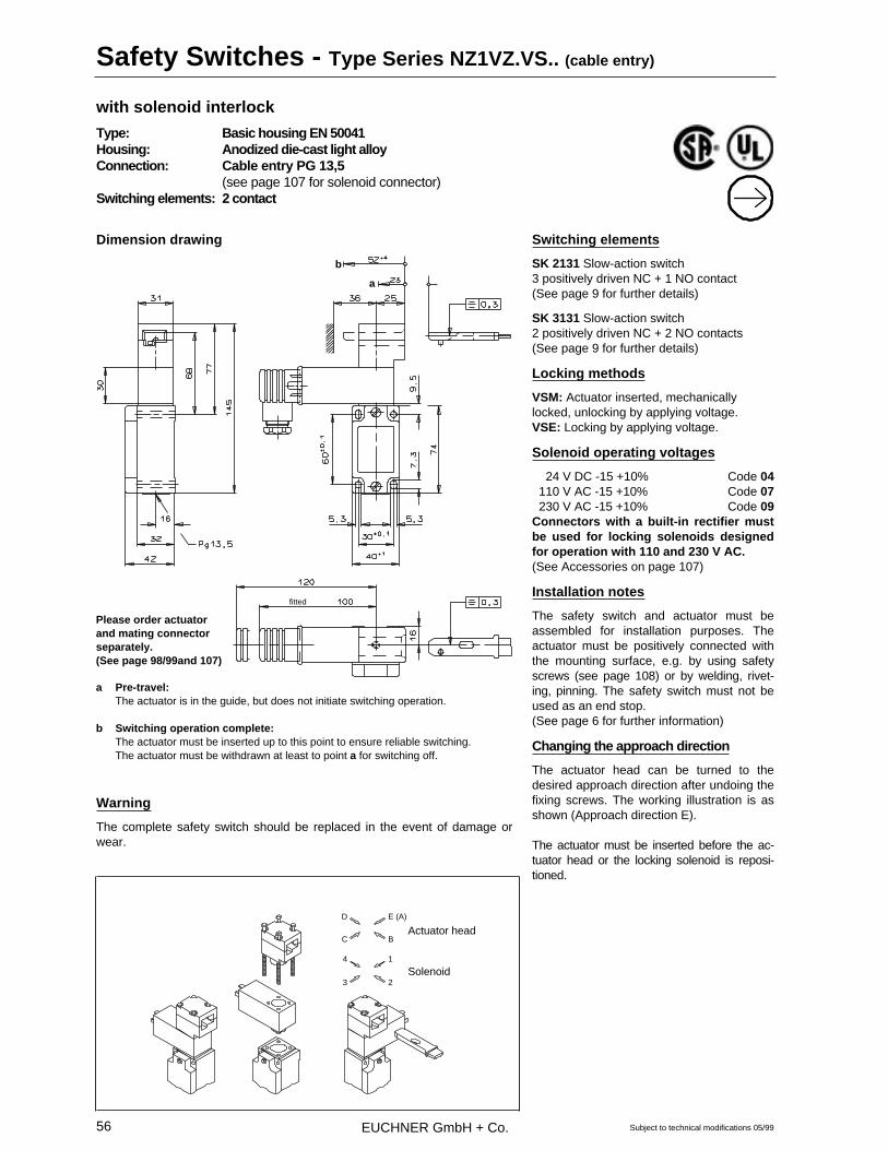
EUCHNER GmbH + Co.56
with solenoid interlock
Type: Basic housing EN 50041Housing: Anodized die-cast light alloyConnection: Cable entry PG 13,5
(see page 107 for solenoid connector)Switching elements: 2 contact
Switching elements
SK 2131 Slow-action switch3 positively driven NC + 1 NO contact(See page 9 for further details)
SK 3131 Slow-action switch2 positively driven NC + 2 NO contacts(See page 9 for further details)
Locking methods
VSM: Actuator inserted, mechanicallylocked, unlocking by applying voltage.VSE: Locking by applying voltage.
Solenoid operating voltages
24 V DC -15 +10% Code 04 110 V AC -15 +10% Code 07 230 V AC -15 +10% Code 09Connectors with a built-in rectifier mustbe used for locking solenoids designedfor operation with 110 and 230 V AC.(See Accessories on page 107)
Installation notes
The safety switch and actuator must beassembled for installation purposes. Theactuator must be positively connected withthe mounting surface, e.g. by using safetyscrews (see page 108) or by welding, rivet-ing, pinning. The safety switch must not beused as an end stop.(See page 6 for further information)
Changing the approach direction
The actuator head can be turned to thedesired approach direction after undoing thefixing screws. The working illustration is asshown (Approach direction E).
The actuator must be inserted before the ac-tuator head or the locking solenoid is reposi-tioned.
Safety Switches - Type Series NZ1VZ.VS.. (cable entry)
Subject to technical modifications 05/99
Dimension drawing
fitted
b
a
Please order actuatorand mating connectorseparately.(See page 98/99and 107)
a Pre-travel:The actuator is in the guide, but does not initiate switching operation.
b Switching operation complete:The actuator must be inserted up to this point to ensure reliable switching.The actuator must be withdrawn at least to point a for switching off.
Warning
The complete safety switch should be replaced in the event of damage orwear.
D
C
4
3
E (A)
B
1
2
Actuator head
Solenoid

EUCHNER GmbH + Co. 57
Technical data
Parameter Value UnitHousing material Anodized die-cast light alloyEnvironmental protection to IEC 529 IP 65Mounting position optionalMechanical service life 2 x 10⁶ Switching cyclesAmbient temperature - 25 to + 80 °CApproach speed max. 20 m/minActuating force 35 NRetaining force in locked condition 1000 NSwitching element SK 2131 SK 3131Contact elements 3 NC + 1 NO 2 NC + 2 NOSwitching principle Slow-actionRated impulse withstand voltage Uimp 4.0 kVRated insulation voltage Ui 250 V≅Utilization category to IEC 947-5-1 AC-15 Ue 230 V Ie 6 A DC-13 Ue 24 V Ie 6 ASwitching voltage min. 12 VSwitching current min. at 24 V 10 mAContact material Silver alloy, gold flashedConnection type Screw terminalCable cross section max. 1.5 mm2
Short-circuit protection (control circuit fuse) slow 10 / fast 20 AWeight (incl. solenoid) approx. 0.7 kgSolenoid:Solenoid operating voltage1) 24 / 110 / 230 V≅ON time 100 %Connected load < 10 W
1) Please enquire about other operating voltages
Safety Switches - Type Series NZ1VZ.VS.. (cable entry)
Subject to technical modifications 05/99
Ordering table
Type- Switch. Appr. Locking Code for sole- Cat. No.series element dir. method noid operating
voltage04 024 = 073 575
-2131 VSM 07 110 ~ 073 576Mech. 09 220 ~ 073 577
Locking 04 024 = 074 495-3131 07 110 ~ 074 496
NZ1VZ E3 09 220 ~ 074 49704 024 = 073 572
-2131 VSE 07 110 ~ 073 573Electr. 09 220 ~ 073 574
Locking 04 024 = 074 498-3131 07 110 ~ 074 499
09 220 ~ 074 500
Ordering example: NZ1VZ with switching element 2131, Mech. locking (VSM), Solenoid voltage24 V DC (04)Type NZ1VZ-2131E3VSM04 Cat. No. 073 575

EUCHNER GmbH + Co.58
with solenoid interlock
Type: Basic housing EN 50041Housing: Anodized die-cast light alloyConnection: Plug connector SR6 (see page 104)
(see page 107 for solenoid connector)Switching elements: 2 contact
Switching elements
ES 528 Slow-action switch1 positively driven NC + 1 NO contactES 538 Slow-action switch2 positively driven NC contacts(See page 8 for further details)
Locking methods
VSM: Actuator inserted, mechanicallylocked, unlocking by applying voltage.VSE: Locking by applying voltage.
Solenoid operating voltages
24 V DC -15 +10% Code 04 110 V AC -15 +10% Code 07 230 V AC -15 +10% Code 09Connectors with a built-in rectifier mustbe used for locking solenoids designedfor operation with 110 and 230 V AC.(See Accessories on page 107)
LED-function display (red)
The function display is available for thevoltage ranges:12-60 V AC/DC (L 060) 110 V AC ±15 % (L 110) 230 V AC ±15 % (L 220)(See page 98 for replacement LED)
Warning
The complete safety switch should be re-placed in the event of damage or wear.
Changing the approach direction
The actuator head can be turned to thedesired approach direction after undoing thefixing screws. The working illustration is asshown (Approach direction E).
The actuator must be inserted before the ac-tuator head or the locking solenoid is reposi-tioned.
Safety Switches - Type Series NZ2VZ.VS.. (plug connector)
Subject to technical modifications 05/99
fitte
d
fitte
d
Dimension drawing
b
a
fitted
Please order actuator andmating connector sepa-rately.(See page 98/99, 104 and 107)
a Pre-travel:The actuator is in the guide, but does not initiate switching operation.
b Switching operation complete:The actuator must be inserted up to this point to ensure reliable switching.The actuator must be withdrawn at least to point a for switching off.
Installation notes
The safety switch and actuator must be assembled for installation purposes.The actuator must be positively connected with the mounting surface, e.g.by using safety screws (see page 108) or by welding, riveting, pinning. Thesafety switch must not be used as an end stop. (See page 6 for further in-formation)
D
C
4
3
E (A)
B
1
2
Actuatorhead
Solenoid
Dimensions plug connector connection SR6

EUCHNER GmbH + Co. 59
Technical data
Parameter Value UnitHousing material Anodized die-cast light alloyEnvironmental protection to IEC 529 IP 65Mounting position optionalMechanical service life 2 x 10⁶ Switching cyclesAmbient temperature - 25 to + 80 °CApproach speed max. 20 m/minActuating force 35 NRetaining force in locked condition 1000 NSwitching element ES 528 ES 538Contact elements 1 NO + 1 NC 2 NC Switching principle Slow-actionRated impulse withstand voltage Uimp 4.0 kVRated insulation voltage Ui 250 V≅Utilization category to IEC 947-5-1 AC-15 Ue 230 V Ie 6 A DC-13 Ue 24 V Ie 6 ASwitching voltage min. 12 VSwitching current min. at 24 V 10 mAContact material Silver alloy, gold flashedConnection type Plug connector 6 + PE (DIN 43651)Short-circuit protection (control circuit fuse) slow 10 / fast 20 AWeight (incl. solenoid) approx. 0.75 kgSolenoid:Solenoid operating voltage1) 24 / 110 / 230 V≅ON time 100 %Connected load < 10 W
1) Please enquire about other operating voltages
Connection diagrams
Safety Switches - Type Series NZ2VZ.VS.. (plug connector)
Subject to technical modifications 05/99
Ordering table
Type- Switch. Appr. Locking Code for sole- Cat. No. Cat. No. Cat. No. Cat. No.series element dir. method noid operating Function display
voltage without L 060 L 110 L 22004 024 037 299 045 856 to order 070 039
-528 VSM 07 110 045 526 to order to order 055 691Mech. 09 220 055 718 072 192 to order 059 098
Locking 04 024 050 428 059 427 to order to order-538 07 110 to order to order 072 202 to order
NZ2VZ.. E3 09 220 to order to order to order 073 49604 024 044 894 046 742 to order 045 954
-528 VSE 07 110 047 758 to order 070 290 055 658Electr. 09 220 045 830 to order to order 043 919
Locking 04 024 047 837 057 921 to order to order-538 07 110 to order to order to order to order
09 220 to order 072 329 to order 070 027
Ordering example: NZ2VZ with switching element 538, electr. locking(VSE), Solenoid voltage24 V DC (04), without Function displayType NZ2VZ-538E3VSE04 Cat. No. 047 837
Switching element ES 528
3
1
4
2
13
21
14
22
5 6
3
1
4
2
13
21
14
22
with LED display
Switching element ES 538
3
1
4
2
11
21
12
22
5 6
3
1
4
2
11
21
12
22
with LED display

EUCHNER GmbH + Co.60
with solenoid interlock
Type: Basic housing EN 50041Housing: Anodized die-cast light alloyConnection: Plug connector SR11 (see page 104)
(see page 107 for solenoid connector)Switching elements: 4 contact
Switching elements
SK 2131 Slow-action switch3 positively driven NC + 1 NO contact(See page 9 for further details)
SK 3131 Slow-action switch2 positively driven NC + 2 NO contacts(See page 9 for further details)
Locking methods
VSM: Actuator inserted, mechanicallylocked, unlocking by applying voltage.VSE: Locking by applying voltage.
Solenoid operating voltages
24 V DC -15 +10% Code 04 110 V AC -15 +10% Code 07 230 V AC -15 +10% Code 09Connectors with a built-in rectifier mustbe used for locking solenoids designedfor operation with 110 and 230 V AC.(See Accessories on page 107)
Installation notes
The safety switch and actuator must beassembled for installation purposes. Theactuator must be positively connected withthe mounting surface, e.g. by using safetyscrews (see page 108) or by welding, rivet-ing, pinning. The safety switch must not beused as an end stop.(See page 6 for further information)
Changing the approach direction
The actuator head can be turned to thedesired approach direction after undoing thefixing screws. The working illustration is asshown (Approach direction E).
The actuator must be inserted before the ac-tuator head or the locking solenoid is reposi-tioned.
Safety Switches - Type Series NZ2VZ.VS.. (plug connector)
Subject to technical modifications 05/99
Dimensions plug connector connection SR11
fitte
d
fitte
d
Dimension drawing
b
a
fitted
Please order actuator andmating connector sepa-rately.(See page 98/99, 104 and 107)
a Pre-travel:The actuator is in the guide, but does not initiate switching operation.
b Switching operation complete:The actuator must be inserted up to this point to ensure reliable switching.The actuator must be withdrawn at least to point a for switching off.
Warning
The complete safety switch should be replaced in the event of damage orwear.
D
C
4
3
E (A)
B
1
2
Actuatorhead
Solenoid

EUCHNER GmbH + Co. 61
Technical data
Parameter Value UnitHousing material Anodized die-cast light alloyEnvironmental protection to IEC 529 IP 65Mounting position optionalMechanical service life 2 x 10⁶ Switching cyclesAmbient temperature - 25 to + 80 °CApproach speed max. 20 m/minActuating force 35 NRetaining force in locked condition 1000 NSwitching element SK 2131 SK 3131Contact elements 3 NC + 1 NO 2 NC + 2 NOSwitching principle Slow-actionRated impulse withstand voltage Uimp 4.0 kVRated insulation voltage Ui 50 V≅Utilization category to IEC 947-5-1 AC-15 Ue 50 V Ie 6 A DC-13 Ue 24 V Ie 6 ASwitching voltage min. 12 VSwitching current min. at 24 V 10 mAContact material Silver alloy, gold flashedConnection type Plug connector 11 + PE (DIN 43651)Short-circuit protection (control circuit fuse) slow 10 / fast 20 AWeight (incl. solenoid) approx. 0.75 kgSolenoid:Solenoid operating voltage1) 24 / 110 / 230 V≅ON time 100 %Connected load < 10 W
1) Please enquire about other operating voltages
Connection diagrams
Safety Switches - Type Series NZ2VZ.VS.. (plug connector)
Subject to technical modifications 05/99
Ordering table
Type- Switch. Appr. Locking Code for sole- Cat. No.series element dir. method noid operating
voltage04 024 074 471
-2131 VSM 07 110 to orderMech. 09 220 to order
Locking 04 024 074 472-3131 07 110 to order
NZ2VZ E3 09 220 to order04 024 074 473
-2131 VSE 07 110 to orderElectr. 09 220 to order
Locking 04 024 074 474-3131 07 110 to order
09 220 to order
Ordering example: NZ2VZ with switching element 2131, Mech. locking (VSM), Solenoid voltage24 V DC (04)Type NZ2VZ-2131E3VSM04 Cat. No. 074 471
Switching element SK 2131
7
5
3
1
8
6
4
2
41
33
21
11
42
34
22
12
Switching element SK 3131
7
5
3
1
8
6
4
2
41
33
21
13
42
34
22
14

EUCHNER GmbH + Co.62
with solenoid interlock and locking monitoring
Housing: Anodized die-cast light alloyActuator head: LeftConnection: Cable entry PG 13,5Switching elements: 2 contact
Switching elements
ES 528 Slow-action switch1 positively driven NC + 1 NO contact(See page 8 for further details)
Locking methods
TZ1: Actuator inserted, mechanicallylocked, unlocking by applying voltage.TZ2: Locking by applying voltage.
Solenoid operating voltages
24 V AC/DC -15 +10% 110 V AC -15 +10% 230 V AC -15 +10%
LED function display
The function display makes it possible tocheck the respective operating state of thesafety switch.
Only Green: Safety circuit closedOnly Red: Key unlocked, safety circuit
open.(See page 45 for further information)
The LED voltage corresponds to the sole-noid operating voltage. Please specify otheroperating voltages in the safety and monitor-ing circuit.
Installation notes
The safety switch and actuator must beassembled for installation purposes. Theactuator must be positively connected withthe mounting surface, e.g. by using safetyscrews (see page 108) or by welding, rivet-ing, pinning. The safety switch must not beused as an end stop.(See page 6 for further information)
Mechanical unlocking mechanism
Safety switches with mechanical locking canbe unlocked by means of the mechanicalunlocking mechanism in the event of powerfailure, for example. The mechanical unlock-ing mechanism can be sealed to preventmanipulation (lead seal set supplied).
Changing the approach direction
The actuator head can be turned to thedesired approach direction after undoing thefixing screws.The working illustration is as shown(Approach direction E).
Safety Switches - Type Series TZ.L.. (head on left - cable entry)
Subject to technical modifications 05/99
E (C)Standard
D
B
Dimension drawing
ba
Mechanicalunlockingmechanism
Please order actuatorseparately.(See page 98/99)
a Pre-travel:The actuator is in the guide, but does not initiate switching operation.
b Switching operation complete:The actuator must be inserted up to this point to ensure reliable switching.The actuator must be withdrawn at least to point a for switching off.
Warning
The complete safety switch must be replaced in the event of damage orwear.
D A
BE (C)
Changing the approach direction

EUCHNER GmbH + Co. 63
Technical data
Parameter Value UnitHousing material Anodized die-cast light alloyColor of housing cover 1) blackEnvironmental protection to IEC 529 IP 67Mounting position optionalMechanical service life 2 x 10⁶ Switching cyclesAmbient temperature - 25 to + 80 °CApproach speed max. 20 m/minActuating force 35 NRetaining force in locked condition 1000 NSwitching element 2 x ES 528Contact elements 1 NO + 1 NC Switching principle Slow-actionRated impulse withstand voltage Uimp 4.0 kVRated insulation voltage Ui 250 V≅Utilization category to IEC 947-5-1 AC-15 Ue 230 V Ie 6 A DC-13 Ue 24 V Ie 6 ASwitching voltage min. 12 VSwitching current min. at 24 V 10 mAContact material Silver alloy, gold flashedConnection type Screw terminalCable cross section max. 1.5 mm2
Short-circuit protection (control circuit fuse) slow 10 / fast 20 AWeight (incl. solenoid) approx. 1,07 kgSolenoid:Solenoid operating voltage 2) 24 / 110 / 230 V≅ON time 100 %Connected load 7 W
1) Red housing cover with inscription „Safety Switch“ available to order 2) Other operating voltages available to order
Safety Switches - Type Series TZ.L.. (head on left - cable entry)
Subject to technical modifications 05/99
Ordering table
Type / locking method Solenoid operatingvoltage
Connection type /cable entry
Cat. No.
TZ1LE.. 024 046 176(mechanical locking) 110 046 177
220 PG 046 178TZ2LE.. 024 045 444(electrical locking) 110 049 831
220 047 916
Ordering example: TZ2LE, Electr. locking, solenoid voltage 230 V ACType TZ2LE220PG Cat. No. 047 916
Switching diagramSafety guard open
Safety guard closed
GN RD
GN RD
Solenoid
Solenoid
Circuit diagram (to be connected by the user)
Depicted:Safety guard closedActuator locked
SK = Safety circuitÜK = Monitoring circuit
Terminal 1 to 6 of PCBterminal strip are shown by �.
Line 2: Safety guard openLine 3: Safety guard closed
and lockedLine 4: Safety guard to unlock (e.g. release
of Zero Speed Indicator)Line 6: Unlocked (released for opening)
GN
RD

EUCHNER GmbH + Co.64
with solenoid interlock and locking monitoring
Housing: Anodized die-cast light alloyActuator head: RightConnection: Cable entry PG 13,5Switching elements: 2 contact
Switching elements
ES 528 Slow-action switch1 positively driven NC + 1 NO contact(See page 8 for further details)
Locking methods
TZ1: Actuator inserted, mechanicallylocked, unlocking by applying voltage.TZ2: Locking by applying voltage.
Solenoid operating voltages
24 V AC/DC -15 +10% 110 V AC -15 +10% 230 V AC -15 +10%
LED function display
The function display makes it possible tocheck the respective operating state of thesafety switch.
Only Green: Safety circuit closedOnly Red: Key unlocked, safety circuit
open.(See page 45 for further information)
The LED voltage corresponds to the sole-noid operating voltage. Please specify otheroperating voltages in the safety and monitor-ing circuit.
Installation notes
The safety switch and actuator must beassembled for installation purposes. Theactuator must be positively connected withthe mounting surface, e.g. by using safetyscrews (see page 108) or by welding, rivet-ing, pinning. The safety switch must not beused as an end stop.(See page 6 for further information)
Mechanical unlocking mechanism
Safety switches with mechanical locking canbe unlocked by means of the mechanicalunlocking mechanism in the event of powerfailure, for example. The mechanical unlock-ing mechanism can be sealed to preventmanipulation (lead seal set supplied).
Changing the approach direction
The actuator head can be turned to thedesired approach direction after undoing thefixing screws.The working illustration is as shown(Approach direction E).
Safety Switches - Type Series TZ.R.. (head on right - cable entry)
Subject to technical modifications 05/99
DE (A)Standard
B
Dimension drawing
Mechanicalunlockingmechanism
ba
Please order actuatorseparately.(See page 98/99)
a Pre-travel:The actuator is in the guide, but does not initiate switching operation.
b Switching operation complete:The actuator must be inserted up to this point to ensure reliable switching.The actuator must be withdrawn at least to point a for switching off.
Warning
The complete safety switch must be replaced in the event of damage orwear.
C
B
D
E (A)
Changing the approach direction

EUCHNER GmbH + Co. 65
Technical data
Parameter Value UnitHousing material Anodized die-cast light alloyColor of housing cover 1) blackEnvironmental protection to IEC 529 IP 67Mounting position optionalMechanical service life 2 x 10⁶ Switching cyclesAmbient temperature - 25 to + 80 °CApproach speed max. 20 m/minActuating force 35 NRetaining force in locked condition 1000 NSwitching element 2 x ES 528Contact elements 1 NO + 1 NC Switching principle Slow-actionRated impulse withstand voltage Uimp 4.0 kVRated insulation voltage Ui 250 V≅Utilization category to IEC 947-5-1 AC-15 Ue 230 V Ie 6 A DC-13 Ue 24 V Ie 6 ASwitching voltage min. 12 VSwitching current min. at 24 V 10 mAContact material Silver alloy, gold flashedConnection type Screw terminalCable cross section max. 1.5 mm2
Short-circuit protection (control circuit fuse) slow 10 / fast 20 AWeight (incl. solenoid) approx. 1,07 kgSolenoid:Solenoid operating voltage 2) 24 / 110 / 230 V≅ON time 100 %Connected load 7 W
1) Red housing cover with inscription „Safety Switch“ available to order 2) Other operating voltages available to order
Safety Switches - Type Series TZ.R.. (head on right - cable entry)
Subject to technical modifications 05/99
Ordering table
Type / locking method Solenoid operatingvoltage
Connection type /cable entry
Cat. No.
TZ1RE.. 024 046 155(mechanical locking) 110 046 156
220 PG 045 448TZ2RE.. 024 046 567(electrical locking) 110 050 002
220 053 241
Ordering example: TZ2RE, Electr. locking, solenoid voltage 110 V ACType TZ2RE110PG Cat. No. 050 002
Switching diagramSafety guard open
Safety guard closed
GN RD
GN RD
Solenoid
Solenoid
Circuit diagram (to be connected by the user)
Depicted:Safety guard closedActuator locked
SK = Safety circuitÜK = Monitoring circuit
Terminal 1 to 6 of PCBterminal strip are shown by �.
Line 2: Safety guard openLine 3: Safety guard closed
and lockedLine 4: Safety guard to unlock (e.g. release
of Zero Speed Indicator)Line 6: Unlocked (released for opening)
GN
RD

EUCHNER GmbH + Co.66
with solenoid interlock and locking monitoring
Housing: Anodized die-cast light alloyActuator head: LeftConnection: Cable entry PG 13,5Switching elements: 4 contact
Dimension drawing
SK 2131 Slow-action switch3 positively driven NC + 1 NO contact(See page 9 for further details)
ÜK 3131 Slow-action switch2 positively driven NC + 2 NO contacts(See page 9 for further details)
Locking methods
TZ1: Actuator inserted, mechanicallylocked, unlocking by applying voltage.TZ2: Locking by applying voltage.
Solenoid operating voltages
24 V AC/DC -15 +10% 110 V AC -15 +10% 230 V AC -15 +10%
LED function display
The function display makes it possible tocheck the respective operating state of thesafety switch. With customer specific wiring.
Only Green: customer specificOnly Red: customer specific(See page 45 for further information)
The LED voltage corresponds to the sole-noid operating voltage.
Installation notes
The safety switch and actuator must beassembled for installation purposes. Theactuator must be positively connected withthe mounting surface, e.g. by using safetyscrews (see page 108) or by welding, rivet-ing, pinning. The safety switch must not beused as an end stop.(See page 6 for further information)
Mechanical unlocking mechanism
Safety switches with mechanical locking canbe unlocked by means of the mechanicalunlocking mechanism in the event of powerfailure, for example. The mechanical unlock-ing mechanism can be sealed to preventmanipulation (lead seal set supplied).
Changing the approach direction
The actuator head can be turned to thedesired approach direction after undoing thefixing screws.The working illustration is as shown(Approach direction E).
Safety Switches - Type Series TZ.L..PG VAB
Subject to technical modifications 05/99
E (C)Standard
D
B
Dimension drawing
ba
Mechanicalunlockingmechanism
Please order actuatorseparately.(See page 98/99)
a Pre-travel:The actuator is in the guide, but does not initiate switching operation.
b Switching operation complete:The actuator must be inserted up to this point to ensure reliable switching.The actuator must be withdrawn at least to point a for switching off.
Warning
The complete safety switch must be replaced in the event of damage orwear.
D A
BE (C)
Changing the approach direction

EUCHNER GmbH + Co. 67
Technical data
Parameter Value UnitHousing material Anodized die-cast light alloyColor of housing cover 1) blackEnvironmental protection to IEC 529 IP 67Mounting position optionalMechanical service life 2 x 10⁶ Switching cyclesAmbient temperature - 25 to + 80 °CApproach speed max. 20 m/minActuating force 35 NRetaining force in locked condition 1000 NSwitching element SK 2131 ÜK 3131Contact elements 3 NC + 1 NO 2 NC + 2 NOSwitching principle Slow-actionRated impulse withstand voltage Uimp 4.0 kVRated insulation voltage Ui 250 V≅Utilization category to IEC 947-5-1 AC-15 Ue 230 V Ie 6 A DC-13 Ue 24 V Ie 6 ASwitching voltage min. 12 VSwitching current min. at 24 V 10 mAContact material Silver alloy, gold flashedConnection type Screw terminalCable cross section max. 1.5 mm2
Short-circuit protection (control circuit fuse) slow 10 / fast 20 AWeight (incl. solenoid) approx. 1,07 kgSolenoid:Solenoid operating voltage 24 AC / DC 110 AC 230 AC VON time 100 %Connected load 7 W
1) Red housing cover with inscription „Safety Switch“ available to order
Safety Switches - Type Series TZ.L..PG VAB
Subject to technical modifications 05/99
Ordering table
Type / locking method Solenoidoperating voltage
Connection type /cable entry
Switching elementswith 4 contacts
Cat. No.
TZ1LE...PG VAB 024 073 197(mechanical locking) 110 073 740
220 PG VAB 073 741TZ2LE...PG VAB 024 074 308(electrical locking) 110 074 310
220 074 312
Ordering example: TZ1LE, mech. locking, solenoid voltage 024 V AC/DC, connection type PGType TZ1LE024PG VAB Cat. No. 073 197
Switching diagramSafety guard open
Safety guard closed
GN RD
GN RD
Solenoid
Solenoid
Circuit diagram (to be connected by the user)
Depicted:Safety guard closedActuator locked
SK = Safety circuitÜK = Monitoring circuit
Terminal 1 to 6 of PCBterminal strip are shown by �.
GN
RD
EUCHNER GmbH + Co.68
with solenoid interlock and locking monitoring
Housing: Anodized die-cast light alloyActuator head: RightConnection: Cable entry PG 13,5Switching elements: 4 contact
Dimension drawing
SK 2131 Slow-action switch3 positively driven NC + 1 NO contact(See page 9 for further details)
ÜK 3131 Slow-action switch2 positively driven NC + 2 NO contacts(See page 9 for further details)
Locking methods
TZ1: Actuator inserted, mechanicallylocked, unlocking by applying voltage.TZ2: Locking by applying voltage.
Solenoid operating voltages
24 V AC/DC -15 +10% 110 V AC -15 +10% 230 V AC -15 +10%
LED function display
The function display makes it possible tocheck the respective operating state of thesafety switch. With customer specific wiring.
Only Green: customer specificOnly Red: customer specific(See page 45 for further information)
The LED voltage corresponds to the sole-noid operating voltage.
Installation notes
The safety switch and actuator must beassembled for installation purposes. Theactuator must be positively connected withthe mounting surface, e.g. by using safetyscrews (see page 108) or by welding, rivet-ing, pinning. The safety switch must not beused as an end stop.(See page 6 for further information)
Mechanical unlocking mechanism
Safety switches with mechanical locking canbe unlocked by means of the mechanicalunlocking mechanism in the event of powerfailure, for example. The mechanical unlock-ing mechanism can be sealed to preventmanipulation (lead seal set supplied).
Changing the approach direction
The actuator head can be turned to thedesired approach direction after undoing thefixing screws.The working illustration is as shown(Approach direction E).
Safety Switches - Type Series TZ.R..PG VAB
Subject to technical modifications 05/99
DE (A)Standard
B
Dimension drawing
Mechanicalunlockingmechanism
ba
Please order actuatorseparately.(See page 98/99)
C
B
D
E (A)
a Pre-travel:The actuator is in the guide, but does not initiate switching operation.
b Switching operation complete:The actuator must be inserted up to this point to ensure reliable switching.The actuator must be withdrawn at least to point a for switching off.
Warning
The complete safety switch must be replaced in the event of damage orwear.
Changing the approach direction

EUCHNER GmbH + Co. 69
Technical data
Parameter Value UnitHousing material Anodized die-cast light alloyColor of housing cover 1) blackEnvironmental protection to IEC 529 IP 67Mounting position optionalMechanical service life 2 x 10⁶ Switching cyclesAmbient temperature - 25 to + 80 °CApproach speed max. 20 m/minActuating force 35 NRetaining force in locked condition 1000 NSwitching element SK 2131 ÜK 3131Contact elements 3 NC + 1 NO 2 NC + 2 NOSwitching principle Slow-actionRated impulse withstand voltage Uimp 4.0 kVRated insulation voltage Ui 250 V≅Utilization category to IEC 947-5-1 AC-15 Ue 230 V Ie 6 A DC-13 Ue 24 V Ie 6 ASwitching voltage min. 12 VSwitching current min. at 24 V 10 mAContact material Silver alloy, gold flashedConnection type Screw terminalCable cross section max. 1.5 mm2
Short-circuit protection (control circuit fuse) slow 10 / fast 20 AWeight (incl. solenoid) approx. 1,07 kgSolenoid:Solenoid operating voltage 24 AC / DC 110 AC 230 AC VON time 100 %Connected load 7 W
1) Red housing cover with inscription „Safety Switch“ available to order
Safety Switches - Type Series TZ.R..PG VAB
Subject to technical modifications 05/99
Ordering table
Type / locking method Solenoidoperating voltage
Connection type /cable entry
Switching elementswith 4 contacts
Cat. No.
TZ1RE...PG VAB 024 073 196(mechanical locking) 110 073 651
220 PG VAB 073 652TZ2RE...PG VAB 024 074 307(electrical locking) 110 074 309
220 074 311
Ordering example: TZ1RE, mech. locking, solenoid voltage 024 V AC/DC, connection type PGType TZ1RE024PG VAB Cat. No. 073 196
Switching diagramSafety guard open
Safety guard closed
GN RD
GN RD
Solenoid
Solenoid
Circuit diagram (to be connected by the user)
Depicted:Safety guard closedActuator locked
SK = Safety circuitÜK = Monitoring circuit
Terminal 1 to 6 of PCBterminal strip are shown by �.
GN
RD

EUCHNER GmbH + Co.70
with solenoid interlock and locking monitoring
Housing: Anodized die-cast light alloyActuator head: LeftConnection: Plug connector SR6 (see page 104)Switching elements: 2 contact
Switching elements
ES 528 Slow-action switch1 positively driven NC + 1 NO contact(See page 8 for further details)
Locking methods
TZ1: Actuator inserted, mechanicallylocked, unlocking by applying voltage.TZ2: Locking by applying voltage.
Solenoid operating voltages
24 V AC/DC -15 +10% 110 V AC -15 +10% 230 V AC -15 +10%
LED function display
The function display makes it possible tocheck the respective operating state of thesafety switch.
Only Green: Safety circuit closedOnly Red: Key unlocked, safety circuit
open.(See page 45 for further information)
The LED voltage corresponds to the sole-noid operating voltage. Please specify otheroperating voltages in the safety and monitor-ing circuit.
Installation notes
The safety switch and actuator must beassembled for installation purposes. Theactuator must be positively connected withthe mounting surface, e.g. by using safetyscrews (see page 108) or by welding, rivet-ing, pinning. The safety switch must not beused as an end stop.(See page 6 for further information)
Mechanical unlocking mechanism
Safety switches with mechanical locking canbe unlocked by means of the mechanicalunlocking mechanism in the event of powerfailure, for example. The mechanical unlock-ing mechanism can be sealed to preventmanipulation (lead seal set supplied).
Changing the approach direction
The actuator head can be turned to thedesired approach direction after undoing thefixing screws.The working illustration is as shown(Approach direction E).
Safety Switches - Type Series TZ.L.. (head on left - plug connector)
Subject to technical modifications 05/99
E (C)Standard
D
B
Dimensions plug connector connection SR6
fitte
d
fitte
d
Dimension drawing
Mechanicalunlockingmechanism
ba
Please order actuatorseparately.(See page 98/99)
a Pre-travel:The actuator is in the guide, but does not initiate switching operation.
b Switching operation complete:The actuator must be inserted up to this point to ensure reliable switching.The actuator must be withdrawn at least to point a for switching off.
Warning
The complete safety switch must be replaced in the event of damage orwear.

EUCHNER GmbH + Co. 71
Technical data
Parameter Value UnitHousing material Anodized die-cast light alloyColor of housing cover 1) blackEnvironmental protection to IEC 529 IP 65Mounting position optionalMechanical service life 2 x 10⁶ Switching cyclesAmbient temperature - 25 to + 80 °CApproach speed max. 20 m/minActuating force 35 NRetaining force in locked condition 1000 NSwitching element 2 x ES 528Contact elements 1 NO + 1 NC Switching principle Slow-actionRated impulse withstand voltage Uimp 4.0 kVRated insulation voltage Ui 250 V≅Utilization category to IEC 947-5-1 AC-15 Ue 230 V Ie 6 A DC-13 Ue 24 V Ie 6 ASwitching voltage min. 12 VSwitching current min. at 24 V 10 mAContact material Silver alloy, gold flashedConnection type Plug connector 6 + PE (DIN 43651)Short-circuit protection (control circuit fuse) slow 10 / fast 20 AWeight (incl. solenoid) approx. 1.14 kgSolenoid:Solenoid operating voltage 2) 24 / 110 / 230 V≅ON time 100 %Connected load 7 W
1) Red housing cover with inscription „Safety Switch“ available to order 2) Other operating voltages available to order
Safety Switches - Type Series TZ.L.. (head on left - plug connector)
Subject to technical modifications 05/99
Ordering table
Type / locking method Solenoid operatingvoltage
Connection type /cable entry
Cat. No.
TZ1LE.. 024 046 502(mechanical locking) 110 046 503
220 SR6 046 504TZ2LE.. 024 049 159(electrical locking) 110 049 831
220 045 450
Ordering example: TZ2LE, Electr. locking, solenoid voltage 230 V ACType TZ2LE220SR6 Cat. No. 045 450
Switching diagramSafety guard open
Safety guard closed
GN RD
GN RD
Solenoid
Solenoid
Circuit diagram (internally wired)
Depicted:Safety guard closedActuator locked
SK = Safety circuitÜK = Monitoring circuit
Terminal 1 to 6 of PCBterminal strip are shown by �.
Line 2: Safety guard openLine 3: Safety guard closed
and lockedLine 4: Safety guard to unlock (e.g. release
of Zero Speed Indicator)Line 6: Unlocked (released for opening)
RD
GN

EUCHNER GmbH + Co.72
with solenoid interlock and locking monitoring
Housing: Anodized die-cast light alloyActuator head: RightConnection: Plug connector SR6 (see page 104)Switching elements: 2 contact
Switching elements
ES 528 Slow-action switch1 positively driven NC + 1 NO contact(See page 8 for further details)
Locking methods
TZ1: Actuator inserted, mechanicallylocked, unlocking by applying voltage.TZ2: Locking by applying voltage.
Solenoid operating voltages
24 V AC/DC -15 +10% 110 V AC -15 +10% 230 V AC -15 +10%
LED function display
The function display makes it possible tocheck the respective operating state of thesafety switch.
Only Green: Safety circuit closedOnly Red: Key unlocked, safety circuit
open.(See page 45 for further information)
The LED voltage corresponds to the sole-noid operating voltage. Please specify otheroperating voltages in the safety and monitor-ing circuit.
Installation notes
The safety switch and actuator must beassembled for installation purposes. Theactuator must be positively connected withthe mounting surface, e.g. by using safetyscrews (see page 108) or by welding, rivet-ing, pinning. The safety switch must not beused as an end stop.(See page 6 for further information)
Mechanical unlocking mechanism
Safety switches with mechanical locking canbe unlocked by means of the mechanicalunlocking mechanism in the event of powerfailure, for example. The mechanical unlock-ing mechanism can be sealed to preventmanipulation (lead seal set supplied).
Changing the approach direction
The actuator head can be turned to thedesired approach direction after undoing thefixing screws.The working illustration is as shown(Approach direction E).
Safety Switches - Type Series TZ.R.. (head on right - plug connector)
Subject to technical modifications 05/99
DE (A)Standard
B
Dimensions plug connector connection SR6
fitte
d
fitte
d
Dimension drawing
Mechanicalunlockingmechanism a
b
Please order actuatorseparately.(See page 98/99)
a Pre-travel:The actuator is in the guide, but does not initiate switching operation.
b Switching operation complete:The actuator must be inserted up to this point to ensure reliable switching.The actuator must be withdrawn at least to point a for switching off.
Warning
The complete safety switch must be replaced in the event of damage orwear.

EUCHNER GmbH + Co. 73
Technical data
Parameter Value UnitHousing material Anodized die-cast light alloyColor of housing cover 1) blackEnvironmental protection to IEC 529 IP 65Mounting position optionalMechanical service life 2 x 10⁶ Switching cyclesAmbient temperature - 25 to + 80 °CApproach speed max. 20 m/minActuating force 35 NRetaining force in locked condition 1000 NSwitching element 2 x ES 528Contact elements 1 NO + 1 NC Switching principle Slow-actionRated impulse withstand voltage Uimp 4.0 kVRated insulation voltage Ui 250 V≅Utilization category to IEC 947-5-1 AC-15 Ue 230 V Ie 6 A DC-13 Ue 24 V Ie 6 ASwitching voltage min. 12 VSwitching current min. at 24 V 10 mAContact material Silver alloy, gold flashedConnection type Plug connector 6 + PE (DIN 43651)Short-circuit protection (control circuit fuse) slow 10 / fast 20 AWeight (incl. solenoid) approx. 1.14 kgSolenoid:Solenoid operating voltage 2) 24 / 110 / 230 V≅ON time 100 %Connected load 7 W
1) Red housing cover with inscription „Safety Switch“ available to order 2) Other operating voltages available to order
Safety Switches - Type Series TZ.R.. (head on right - plug connector)
Subject to technical modifications 05/99
Ordering table
Type / locking method Solenoid operatingvoltage
Connection type /cable entry
Cat. No.
TZ1RE.. 024 046 190(mechanical locking) 110 046 191
220 SR6 051 879TZ2RE.. 024 049 102(electrical locking) 110 049 238
220 047 937
Ordering example: TZ1RE, mech. locking, solenoid voltage 024 V ACType TZ1RE024SR6 Cat. No. 046 190
Switching diagramSafety guard open
Safety guard closed
GN RD
GN RD
Solenoid
Solenoid
Circuit diagram (internally wired)
Depicted:Safety guard closedActuator locked
SK = Safety circuitÜK = Monitoring circuit
Terminal 1 to 6 of PCBterminal strip are shown by �.
Line 2: Safety guard openLine 3: Safety guard closed
and lockedLine 4: Safety guard to unlock (e.g. release
of Zero Speed Indicator)Line 6: Unlocked (released for opening)
RD
GN

EUCHNER GmbH + Co.74
with solenoid interlock and locking monitoring
Housing: Anodized die-cast light alloyActuator head: LeftConnection: Plug connector SR11 (see page 104)Switching elements: 2 contact
Switching elements
ES 528 Slow-action switch1 positively driven NC + 1 NO contact(See page 8 for further details)
Locking methods
TZ1: Actuator inserted, mechanicallylocked, unlocking by applying voltage.TZ2: Locking by applying voltage.
Solenoid operating voltages
24 V AC/DC -15 +10%
LED function display
The function display makes it possible tocheck the respective operating state of thesafety switch.
Green: dependent on wiring:Power on / actuator unlocked
Red: customer specific(See page 45 for further information)
The LED voltage corresponds to the sole-noid operating voltage. Please specify otheroperating voltages in the safety and monitor-ing circuit.
Installation notes
The safety switch and actuator must beassembled for installation purposes. Theactuator must be positively connected withthe mounting surface, e.g. by using safetyscrews (see page 108) or by welding, rivet-ing, pinning. The safety switch must not beused as an end stop.(See page 6 for further information)
Mechanical unlocking mechanism
Safety switches with mechanical locking canbe unlocked by means of the mechanicalunlocking mechanism in the event of powerfailure, for example. The mechanical unlock-ing mechanism can be sealed to preventmanipulation (lead seal set supplied).
Changing the approach direction
The actuator head can be turned to thedesired approach direction after undoing thefixing screws.The working illustration is as shown(Approach direction E).
Safety Switches - Type Series TZ.L.. (head on left - plug connector)
Subject to technical modifications 05/99
E (C)Standard
D
B
Dimensions plug connector connection SR11
fitte
dfitte
d
Dimension drawing
Mechanicalunlockingmechanism
ba
Please order actuatorseparately.(See page 98/99)
a Pre-travel:The actuator is in the guide, but does not initiate switching operation.
b Switching operation complete:The actuator must be inserted up to this point to ensure reliable switching.The actuator must be withdrawn at least to point a for switching off.
Warning
The complete safety switch must be replaced in the event of damage orwear.

EUCHNER GmbH + Co. 75
Technical data
Parameter Value UnitHousing material Anodized die-cast light alloyColor of housing cover blackEnvironmental protection to IEC 529 IP 65Mounting position optionalMechanical service life 2 x 10⁶ Switching cyclesAmbient temperature - 25 to + 80 °CApproach speed max. 20 m/minActuating force 35 NRetaining force in locked condition 1000 NSwitching element 2 x ES 528Contact elements 1 NO + 1 NC Switching principle Slow-actionRated impulse withstand voltage Uimp 4.0 kVRated insulation voltage Ui 50 V≅Utilization category to IEC 947-5-1 AC-15 Ue 50 V Ie 6 A DC-13 Ue 24 V Ie 6 ASwitching voltage min. 12 VSwitching current min. at 24 V 10 mAContact material Silver alloy, gold flashedConnection type Plug connector 11 + PE (DIN 43651)Short-circuit protection (control circuit fuse) slow 10 / fast 20 AWeight (incl. solenoid) approx. 1.14 kgSolenoid:Solenoid operating voltage 24 / 110 / 230 V≅ON time 100 %Connected load 7 W
Safety Switches - Type Series TZ.L.. (head on left - plug connector)
Subject to technical modifications 05/99
Ordering table
Type / locking method Solenoid operatingvoltage
Connection type /cable entry
Cat. No.
TZ1LE..(mechanical locking)TZ2LE..(electrical locking)
Ordering example: TZ2LE, Electr. locking, solenoid voltage 024 V ACType TZ2LE024SR11 Cat. No. 070 958
Switching diagramSafety guard open
Safety guard closed
GN RD
GN RD
Solenoid
Solenoid
Circuit diagram (internally wired)
Depicted:Safety guard closedActuator locked
SK = Safety circuitÜK = Monitoring circuit
Terminal 1 to 6 of PCBterminal strip are shown by �.
070 828
070 958024 SR11
RD
GN

EUCHNER GmbH + Co.76
with solenoid interlock and locking monitoring
Housing: Anodized die-cast light alloyActuator head: RightConnection: Plug connector SR11 (see page 104)Switching elements: 2 contact
Switching elements
ES 528 Slow-action switch1 positively driven NC + 1 NO contact(See page 8 for further details)
Locking methods
TZ1: Actuator inserted, mechanicallylocked, unlocking by applying voltage.TZ2: Locking by applying voltage.
Solenoid operating voltages
24 V AC/DC -15 +10%
LED function display
The function display makes it possible tocheck the respective operating state of thesafety switch.
Green: dependent on wiring:Power on / actuator unlocked
Red: customer specific(See page 45 for further information)
The LED voltage corresponds to the sole-noid operating voltage. Please specify otheroperating voltages in the safety and monitor-ing circuit.
Installation notes
The safety switch and actuator must beassembled for installation purposes. Theactuator must be positively connected withthe mounting surface, e.g. by using safetyscrews (see page 108) or by welding, rivet-ing, pinning. The safety switch must not beused as an end stop.(See page 6 for further information)
Mechanical unlocking mechanism
Safety switches with mechanical locking canbe unlocked by means of the mechanicalunlocking mechanism in the event of powerfailure, for example. The mechanical unlock-ing mechanism can be sealed to preventmanipulation (lead seal set supplied).
Changing the approach direction
The actuator head can be turned to thedesired approach direction after undoing thefixing screws.The working illustration is as shown(Approach direction E).
Safety Switches - Type Series TZ.R.. (head on right - plug connector)
Subject to technical modifications 05/99
DE (A)Standard
B
Dimensions plug connector connection SR11
fitte
d fitte
d
Dimension drawing
Mechanicalunlockingmechanism a
b
Please order actuatorseparately.(See page 98/99)
a Pre-travel:The actuator is in the guide, but does not initiate switching operation.
b Switching operation complete:The actuator must be inserted up to this point to ensure reliable switching.The actuator must be withdrawn at least to point a for switching off.
Warning
The complete safety switch must be replaced in the event of damage orwear.

EUCHNER GmbH + Co. 77
Technical data
Parameter Value UnitHousing material Anodized die-cast light alloyColor of housing cover blackEnvironmental protection to IEC 529 IP 65Mounting position optionalMechanical service life 2 x 10⁶ Switching cyclesAmbient temperature - 25 to + 80 °CApproach speed max. 20 m/minActuating force 35 NRetaining force in locked condition 1000 NSwitching element 2 x ES 528Contact elements 1 NO + 1 NC Switching principle Slow-actionRated impulse withstand voltage Uimp 4.0 kVRated insulation voltage Ui 50 V≅Utilization category to IEC 947-5-1 AC-15 Ue 50 V Ie 6 A DC-13 Ue 24 V Ie 6 ASwitching voltage min. 12 VSwitching current min. at 24 V 10 mAContact material Silver alloy, gold flashedConnection type Plug connector 11 + PE (DIN 43651)Short-circuit protection (control circuit fuse) slow 10 / fast 20 AWeight (incl. solenoid) approx. 1.14 kgSolenoid:Solenoid operating voltage 24 V≅ON time 100 %Connected load 7 W
Safety Switches - Type Series TZ.R.. (head on right - plug connector)
Subject to technical modifications 05/99
Ordering table
Type / locking method Solenoid operatingvoltage
Connection type /cable entry
Cat. No.
TZ1RE..(mechanical locking)TZ2RE..(electrical locking)
Ordering example: TZ1RE, mech. locking, solenoid voltage 024 V ACType TZ1RE024SR11 Cat. No. 070 826
Switching diagramSafety guard open
Safety guard closed
GN RD
GN RD
Solenoid
Solenoid
Circuit diagram (internally wired)
Depicted:Safety guard closedActuator locked
SK = Safety circuitÜK = Monitoring circuit
Terminal 1 to 6 of PCBterminal strip are shown by �.
070 826024 SR11
070 957
RD
GN

EUCHNER GmbH + Co.78
with solenoid interlock and locking monitoring
Housing: Anodized die-cast light alloyActuator head: LeftConnection: Plug connector RC18 (see page 105)Switching elements: 4 contact
Switching elements
SK 2131 Slow-action switch3 positively driven NC + 1 NO contact(See page 9 for further details)
ÜK 3131 Slow-action switch2 positively driven NC + 2 NO contacts(See page 9 for further details)
Locking methods
TZ1: Actuator inserted, mechanicallylocked, unlocking by applying voltage.TZ2: Locking by applying voltage.
Solenoid operating voltages
24 V AC/DC -15 +10%
LED function display
The function display makes it possible tocheck the respective operating state of thesafety switch. With customer specific wiring.
Only Green: customer specificOnly Red: customer specific(See page 45 for further information)
The LED voltage corresponds to the sole-noid operating voltage.
Installation notes
The safety switch and actuator must beassembled for installation purposes. Theactuator must be positively connected withthe mounting surface, e.g. by using safetyscrews (see page 108) or by welding, rivet-ing, pinning. The safety switch must not beused as an end stop.(See page 6 for further information)
Mechanical unlocking mechanism
Safety switches with mechanical locking canbe unlocked by means of the mechanicalunlocking mechanism in the event of powerfailure, for example. The mechanical unlock-ing mechanism can be sealed to preventmanipulation (lead seal set supplied).
Changing the approach direction
The actuator head can be turned to thedesired approach direction after undoing thefixing screws.The working illustration is as shown(Approach direction E).
Safety Switches - Type Series TZ.L..RC18 VAB
Subject to technical modifications 05/99
E (C)Standard
D
B
Dimensions plug connector connection RC18
Dimension drawing
Mechanicalunlockingmechanism
ba
Please order actuatorseparately.(See page 98/99)
a Pre-travel:The actuator is in the guide, but does not initiate switching operation.
b Switching operation complete:The actuator must be inserted up to this point to ensure reliable switching.The actuator must be withdrawn at least to point a for switching off.
Warning
The complete safety switch must be replaced in the event of damage orwear.
fitte
d
fitte
d

EUCHNER GmbH + Co. 79
Technical data
Parameter Value UnitHousing material Anodized die-cast light alloyColor of housing cover blackEnvironmental protection to IEC 529 IP 65Mounting position optionalMechanical service life 2 x 10⁶ Switching cyclesAmbient temperature - 25 to + 80 °CApproach speed max. 20 m/minActuating force 35 NRetaining force in locked condition 1000 NSwitching element SK 2131 ÜK 3131Contact elements 3 NC + 1 NO 2 NC + 2 NOSwitching principle Slow-actionRated impulse withstand voltage Uimp 4.0 kVRated insulation voltage Ui 32 V≅Utilization category to IEC 947-5-1 AC-15 Ue 32 V Ie 6 A DC-13 Ue 24 V Ie 6 ASwitching voltage min. 12 VSwitching current min. at 24 V 10 mAContact material Silver alloy, gold flashedConnection type Plug connector RC18 (18 + PE), 1.0 mm max. conducterShort-circuit protection (control circuit fuse) slow 10 / fast 20 AWeight (incl. solenoid) approx. 1.14 kgSolenoid:Solenoid operating voltage 24 V≅ON time 100 %Connected load 7 W
1) Red housing cover with inscription „Safety Switch“ available to order
Safety Switches - Type Series TZ.L..RC18 VAB
Subject to technical modifications 05/99
Ordering table
Type / locking method Solenoidoperating voltage
Connection type /cable entry
Switching elementswith 4 contacts
Cat. No.
TZ1LE..(mechanical locking)TZ2LE..(electrical locking)
Ordering example: TZ1LE, mech. locking, solenoid voltage 024 V AC/DC, plug connector RC18Type TZ1LE024RC18 VAB Cat. No. 074 654
Switching diagramSafety guard open
Safety guard closed
GN RD
GN RD
Solenoid
Solenoid
Circuit diagram (internally wired)
Depicted:Safety guard closedActuator locked
SK = Safety circuitÜK = Monitoring circuit
Terminal 1 to 6 of PCBterminal strip are shown by �.
GN
RD
024 074 654RC18 VAB
024 074 656

EUCHNER GmbH + Co.80
with solenoid interlock and locking monitoring
Housing: Anodized die-cast light alloyActuator head: RightConnection: Plug connector RC18 (see page 105)Switching elements: 4 contact
Switching elements
SK 2131 Slow-action switch3 positively driven NC + 1 NO contact(See page 9 for further details)
ÜK 3131 Slow-action switch2 positively driven NC + 2 NO contacts(See page 9 for further details)
Locking methods
TZ1: Actuator inserted, mechanicallylocked, unlocking by applying voltage.TZ2: Locking by applying voltage.
Solenoid operating voltages
24 V AC/DC -15 +10%
LED function display
The function display makes it possible tocheck the respective operating state of thesafety switch.With customer specific wiring.
Only Green: customer specificOnly Red: customer specific(See page 45 for further information)
The LED voltage corresponds to the sole-noid operating voltage.
Installation notes
The safety switch and actuator must beassembled for installation purposes. Theactuator must be positively connected withthe mounting surface, e.g. by using safetyscrews (see page 108) or by welding, rivet-ing, pinning. The safety switch must not beused as an end stop.(See page 6 for further information)
Mechanical unlocking mechanism
Safety switches with mechanical locking canbe unlocked by means of the mechanicalunlocking mechanism in the event of powerfailure, for example. The mechanical unlock-ing mechanism can be sealed to preventmanipulation (lead seal set supplied).
Changing the approach direction
The actuator head can be turned to thedesired approach direction after undoing thefixing screws.The working illustration is as shown(Approach direction E).
Safety Switches - Type Series TZ.R..RC18 VAB
Subject to technical modifications 05/99
DE (A)Standard
B
Dimensions plug connector connection RC18
Dimension drawing
Mechanicalunlockingmechanism a
b
Please order actuatorseparately.(See page 98/99)
a Pre-travel:The actuator is in the guide, but does not initiate switching operation.
b Switching operation complete:The actuator must be inserted up to this point to ensure reliable switching.The actuator must be withdrawn at least to point a for switching off.
Warning
The complete safety switch must be replaced in the event of damage orwear.
fitte
d
fitte
d

EUCHNER GmbH + Co. 81
Technical data
Parameter Value UnitHousing material Anodized die-cast light alloyColor of housing cover blackEnvironmental protection to IEC 529 IP 65Mounting position optionalMechanical service life 2 x 10⁶ Switching cyclesAmbient temperature - 25 to + 80 °CApproach speed max. 20 m/minActuating force 35 NRetaining force in locked condition 1000 NSwitching element SK 2131 ÜK 3131Contact elements 3 NC + 1 NO 2 NC + 2 NOSwitching principle Slow-actionRated impulse withstand voltage Uimp 4.0 kVRated insulation voltage Ui 32 V≅Utilization category to IEC 947-5-1 AC-15 Ue 32 V Ie 6 A DC-13 Ue 24 V Ie 6 ASwitching voltage min. 12 VSwitching current min. at 24 V 10 mAContact material Silver alloy, gold flashedConnection type Plug connector RC18 (18 + PE), 1.0 mm max. conducterShort-circuit protection (control circuit fuse) slow 10 / fast 20 AWeight (incl. solenoid) approx. 1.14 kgSolenoid:Solenoid operating voltage 24 V≅ON time 100 %Connected load 7 W
1) Red housing cover with inscription „Safety Switch“ available to order
Safety Switches - Type Series TZ.R..RC18 VAB
Subject to technical modifications 05/99
Ordering table
Type / locking method Solenoidoperating voltage
Connection type /cable entry
Switching elementswith 4 contacts
Cat. No.
TZ1RE..(mechanical locking)TZ2RE..(electrical locking)
Ordering example: TZ1RE, mech. locking, solenoid voltage 024 V AC/DC, plug connector RC18Type TZ1RE024RC18 VAB Cat. No. 074 653
Switching diagramSafety guard open
Safety guard closed
GN RD
GN RD
Solenoid
Solenoid
Circuit diagram (internally wired)
Depicted:Safety guard closedActuator locked
SK = Safety circuitÜK = Monitoring circuit
Terminal 1 to 6 of PCBterminal strip are shown by �.
024 074 653
024 074 655RC18 VAB
GN
RD

EUCHNER GmbH + Co.82
Version: DaimlerChrysler
Type: Basic housing EN 50041Housing: Anodized die-cast light alloyConnection: Plug connector (Type Amphenol-Tuchel,
EUCHNER Cat No. 043 861)Switching element: 2 contact
Technical data as for standard versi-on, page 50.
Differences compared with standardversion
�Protective plate for actuator head�Special wiring, see circuit diagram�Plug connector connection:
(Straight mating connector Cat. No.043 861, Type Amphenol-Tuchel, Type CI6-1)
Switching element
ES 538 Slow-action switch2 NC contacts(See page 8 for further details)
Installation notes
The safety switch and actuator must beassembled for installation purposes. Theactuator must be positively connected withthe mounting surface, e.g. by using safetyscrews (see page 108) or by welding, rivet-ing, pinning. The safety switch must not beused as an end stop.(See page 6 for further information)
Safety Switches - Type Series NZ2VZ..- Special version
Subject to technical modifications 05/99
Dimension drawing
Approach directionright E
Please order actuatorseparately.(See pages 98/99)
Version C1420(for the appropriate enabling switch typeZSA2B2G10B please refer to page 122)
Version C1701(for the appropriate enabling switch typeZSA2B4G10B please refer to page 123)
a Pre-travel:Actuator is in the guide, but does not initiate switching operation.
b Switching operation complete:The actuator must be inserted up to this point to ensure reliable switching.The actuator must be withdrawn at least to point a for switching off.
Changing the approach direction
E
Warning
The complete safety switch should be replaced in the event of damage orwear.
Ordering table
Approach direction Type Cat. No.E NZ2VZ-538EC1420 043 296E NZ2VZ-538EC1701 071 200

EUCHNER GmbH + Co. 83
Version: VW / Audi
Type: Basic housing EN 50041Housing : Anodized die-cast light alloyConnection: Cable entry PG 13,5Switching element: 2 contact
Technical data as for standard versi-on, page 46.
Differences compared with standardversion
�Protective plate for actuator head
Switching element
ES 538 Slow-action switch2 NC contacts(See page 8 for further details)
Installation notes
The safety switch and actuator must beassembled for installation purposes. Theactuator must be positively connected withthe mounting surface, e.g. by using safetyscrews (see page 108) or by welding, rivet-ing, pinning. The safety switch must not beused as an end stop.(See page 6 for further information)
Safety Switches - Type Series NZ1VZ..- Special version
Subject to technical modifications 05/99
Changing the approach direction
Dimension drawing
Approach directionright E
Please order actuatorseparately.(See pages 98/99)
Warning
The complete safety switch should be replaced in the event of damage orwear.
Ordering table
Approach direction Type Cat. No.E NZ1VZ-538EC1233 070 268
a Pre-travel:Actuator is in the guide, but does not initiate switching operation.
b Switching operation complete:The actuator must be inserted up to this point to ensure reliable switching.The actuator must be withdrawn at least to point a for switching off.

EUCHNER GmbH + Co.84
Type: Basic housing EN 50041Housing: Anodized die-cast light alloyConnection: Cable entry PG 13,5Switching element: 4 contact
Technical data as for standard versi-on, page 48.
Differences compared with standardversion
�Switching element with 4 positively driven NC
Switching element
ES 2121 Slow-action switch4 positively driven NC(See page 8 for further details)
Installation notes
The safety switch and actuator must beassembled for installation purposes. Theactuator must be positively connected withthe mounting surface, e.g. by using safetyscrews (see page 108) or by welding, rivet-ing, pinning. The safety switch must not beused as an end stop.(See page 6 for further information)
Safety Switches - Type Series NZ1VZ..- Special version
Subject to technical modifications 05/99
Changing the approach direction
Dimension drawing
b
a
Warning
The complete safety switch should be replaced in the event of damage orwear.
Ordering table (further types to order)
Approach direction Type Cat. No.E NZ1VZ-2121E 075 872
a Pre-travel:Actuator is in the guide, but does not initiate switching operation.
b Switching operation complete:The actuator must be inserted up to this point to ensure reliable switching.The actuator must be withdrawn at least to point a for switching off.
Please order actuatorseparately.(See pages 98/99)

EUCHNER GmbH + Co. 85
Type: Basic housing EN 50041Housing: Anodized die-cast light alloyConnection: QUICKON-quick connectionSwitching element: 2 contact
Technical data as for standard versi-on, page 46.
Differences compared with standardversion
�QUICKON-quick connection(made by Phoenix Contact)
Switching element
ES 538 Slow-action switch2 NC contacts(See page 8 for further details)
Connection diagramm
Installation notes
The safety switch and actuator must beassembled for installation purposes. Theactuator must be positively connected withthe mounting surface, e.g. by using safetyscrews (see page 108) or by welding, rivet-ing, pinning. The safety switch must not beused as an end stop.(See page 6 for further information)
Safety Switches - Type Series NZ4VZ..- Special version
Subject to technical modifications 05/99
Changing the approach direction
Dimension drawing
Approach directionright E
+4
23
52
36 25
38
31
6
47
115
60±0
,1
74+1
30±0,1
40 +1
5,3
5,3
9,5
7,3
16
16
32
42
35
b
a
1211
21 2221
3
Two safety screws forthe actuating head areincluded with eachswitch
Please order actuatorseparately.(See pages 98/99)
Warning
The complete safety switch should be replaced in the event of damage orwear.
Ordering table (further types to order)
Approach direction Type Cat. No.E NZ4VZ-538EC1819 076 245
a Pre-travel:Actuator is in the guide, but does not initiate switching operation.
b Switching operation complete:The actuator must be inserted up to this point to ensure reliable switching.The actuator must be withdrawn at least to point a for switching off.

EUCHNER GmbH + Co.86
Version: VW / Audi
Housing: Anodized die-cast light alloyActuator head: Left or rightConnection: Plug connector SR6 (see page 104)Switching elements: 2 contact
Technical data as for standard versi-on, page 70.
Differences compared with standardversion
�Protective plate for actuator head�Special wiring see circuit diagram�No mechanical unlocking mechanism�LED function display only for solenoid
locking
Installation notes
The safety switch and actuator must beassembled for installation purposes. Theactuator must be positively connected withthe mounting surface, e.g. by using safetyscrews (see page 108) or by welding, rivet-ing, pinning. The safety switch must not beused as an end stop.(See page 6 for further information)
Safety Switches - Type Series TZ..- Special version
Subject to technical modifications 05/99
Circuit diagram (internally wired)
Depicted:Safety guard closedActuator locked
SK = Safety circuitÜK = Monitoring circuit
Terminal 1 to 6 of PCBterminal strip are shown by �.
Dimension drawing
Actuator head on left Actuator head on right
Please order actuatorseparately.(See pages 98/99)
Warning
The complete safety switch must be replaced in the event of damage orwear.
Ordering table
Solenoid operating Actuator head left Actuator head rightvoltage Type Cat. No. Type Cat. No.
230 V AC TZ1LC230-048228 048 228 TZ1RA230-048492 048 492042 V AC TZ1LC042-045178 045 178 TZ1RA042-045181 045 181
024 V AC/DC TZ1LC024-045177 045 177 TZ1RA024-045180 045 180
a Pre-travel:The actuator is in the guide, but does not initiate switching operation.
b Switching operation complete:The actuator must be inserted up to this point to ensure reliable switching.The actuator must be withdrawn at least to point a for switching off
Switching diagramSafety guard open
Safety guard closed
GN
GN
Solenoid
SolenoidGN

EUCHNER GmbH + Co. 87
Version: VW / Audi
Housing: Anodized die-cast light alloyActuator head: Left or rightConnection: Plug connector SR11 (see page 104)Switching elements: 2 contacts
Technical data as for standard versi-on, page 74.
Differences compared with standardversion
�Protective plate for actuator head
Installation notes
The safety switch and actuator must beassembled for installation purposes. Theactuator must be positively connected withthe mounting surface, e.g. by using safetyscrews (see page 108) or by welding, rivet-ing, pinning. The safety switch must not beused as an end stop.(See page 6 for further information)
Safety Switches - Type Series TZ..- Special version
Subject to technical modifications 05/99
Circuit diagram (internally wired)
Depicted:Safety guard closedActuator locked
SK = Safety circuitÜK = Monitoring circuit
Terminal 1 to 6 of PCBterminal strip are shown by �.
Dimension drawing
Actuator head on left Actuator head on right
a a
b bMechanical unlocking
mechanism
Please orderactuator separately.(See pages 98/99)
Warning
The complete safety switch must be replaced in the event of damage orwear.
Ordering table
Solenoid operating Actuator head left Actuator head rightvoltage Type Cat. No. Type Cat. No.
024 V AC/DC TZ1LE024SR11-072567 072 567 TZ1RE024SR11-072569 072 569
a Pre-travel:The actuator is in the guide, but does not initiate switching operation.
b Switching operation complete:The actuator must be inserted up to this point to ensure reliable switching.The actuator must be withdrawn at least to point a for switching off.
RD
GN

EUCHNER GmbH + Co.88
Version: Ford
Housing: Anodized die-cast light alloyActuator head: Left or rightConnection: Cable entry PG 13,5Switching elements: 2 contacts
Technical data as for standard versi-on, page 62.
Differences compared with standardversion
�Protective plate for actuator head�Safety switches are supplied for the ope-
rating voltage 24 V AC/DC (solenoid inter-lock and function display)
�No mechanical unlocking mechanism
Installation notes
The safety switch and actuator must beassembled for installation purposes. Theactuator must be positively connected withthe mounting surface, e.g. by using safetyscrews (see page 108) or by welding, rivet-ing, pinning. The safety switch must not beused as an end stop.(See page 6 for further information)
Safety Switches - Type Series TZ..- Special version
Subject to technical modifications 05/99
Dimension drawing
Actuator head left Actuator head right
ab
a
b
PG 13,5
Please order actuatorseparately.(See pages 98/99)
Warning
The complete safety switch must be replaced in the event of damage orwear.
Ordering table
Solenoid operating Actuator head left Actuator head rightvoltage Type Cat. No. Type Cat. No.
024 V AC/DC TZ1LE024PG-C1623 055 068 TZ1RE024PG-C1623 055 066
a Pre-travel:Actuator is in the guide, but does not initiate switching operation.
b Switching operation complete:The actuator must be inserted up to this point to ensure reliable switching.The actuator must be withdrawn at least to point a for switching off.

EUCHNER GmbH + Co. 89
Housing: Anodized die-cast light alloyActuator head: Left or rightConnection: Plug connector RC18..-C1825
(see page 105)Switching elements: 4 contact
Technical data as for standard versi-on, page 78-81.
Differences compared with standardversion
�Modified wiring
Installation notes
The safety switch and actuator must beassembled for installation purposes. Theactuator must be positively connected withthe mounting surface, e.g. by using safetyscrews (see page 108) or by welding, rivet-ing, pinning. The safety switch must not beused as an end stop.(See page 6 for further information)
Warning
The complete safety switch must be re-placed in the event of damage or wear.
Safety Switches - Type Series TZ..- Special version
Subject to technical modifications 05/99
Dimension drawing
Actuator head left
36
a
c52 +4
23
18
110
35
110
100
3610
0
31
40
25
20
GN RD
Ordering table
Solenoid opera- Actuator head left Actuator head rightting voltage Type Cat. No. Type Cat. No.
024 V AC/DC TZ1LE024RC18VAB-C1826 077 039 TZ1RE024RC18VAB-C1826 077 037
a Pre-travel:The actuator is in the guide, but does not initiate switching operation.
b Switching operation complete:The actuator must be inserted up to this point to ensure reliable switching.The actuator must be withdrawn at least to point a for switching off.
Please order actuatorseparately.(See page 98/99)
Circuit diagram (internally wired)
Depicted:Safety guard closedActuator locked
SK = Safety circuitÜK = Monitoring circuit
Terminal 1 to 6 of PCBterminal strip are shown by �.
GN
RD
Pole pattern diagramRC18..-C1825(seen from the plugged side)
Pin
18
19
15
6
1211
10
9
8
75
4
3
2
1
17
1614
13
13
1416
17
1
2
3
4
57
8
9
10
11
6
15
19
18
12
Socket
extended pinwith directconnection toouter metalshell forscreen/PEconnection
with directconnection toouter shell forscreen/PEconnection

EUCHNER GmbH + Co.90
Housing: Anodized die-cast light alloyActuator head: Left or rightConnection: Plug connector RC18..-C1825 (see page 105)
and Plug connector RC12 for enabling switchSwitching elements: 4 contact
Technical data as for standard versi-on, page 78-81.
Differences compared with standardversion
�Modified wiring�Connector RC12 with 11 pins (made by
CONINVERS) for connection of an enab-ling switch (see page 117)
�No mechanical unlocking mechanism�Dust cap included in delivery
Installation notes
The safety switch and actuator must beassembled for installation purposes. Theactuator must be positively connected withthe mounting surface, e.g. by using safetyscrews (see page 108) or by welding, rivet-ing, pinning. The safety switch must not beused as an end stop.(See page 6 for further information)
Warning
The complete safety switch must be re-placed in the event of damage or wear.
Safety Switches - Type Series TZ..- Special version
Subject to technical modifications 05/99
Dimension drawing
a
c
36
52 +4
23
18GN RD
110
110
100
3610
0
31
40
25
20
15
3529
Actuator head left
Please order actuatorseparately.(See page 98/99)
RC12 RC18
Ordering table
Solenoid opera- Actuator head left Actuator head rightting voltage Type Cat. No. Type Cat. No.
024 V AC/DC TZ2LE024RC18VAB-C1803 075 955 TZ2RE024RC18VAB-C1803 077 149
a Pre-travel:The actuator is in the guide, but does not initiate switching operation.
b Switching operation complete:The actuator must be inserted up to this point to ensure reliable switching.The actuator must be withdrawn at least to point a for switching off.
Circuit diagram (internally wired)
Depicted:Safety guard closedActuator locked
SK = Safety circuitÜK = Monitoring circuit
Terminal 1 to 6 of PCBterminal strip are shown by �.
SK
ÜK
41
33
42
34 5
1
11
PE/12
6 19
LEDGN
LEDRD
2221
11 12
3
1413
21 22 10
13
8
1434
42
33
41
15
16
1 2
5 6
Zustimm-einheit
2
4
9
17
18
1
5
9
10
11
12
3 4
3
27
ZSB1
ZSB2
Pole pattern diagramRC18..-C1825 RC12
(seen from the plugged side)
Pin
18
19
15
6
1211
10
9
8
75
4
3
2
1
17
1614
13
13
1416
17
1
2
3
4
57
8
9
10
11
6
15
19
18
12
1
2
3
4 5
6
7
89
1210
11
11
1012
98
7
6
5 4
3
2
1
Socket
extended pinwith directconnectionto outermetal shellfor screen/PE connec-tion
direct connec-tion to outershell forscreen/PEconnection

EUCHNER GmbH + Co. 91
Version: DaimlerChrysler Mannheim(all other plants standard version)
Housing: Anodized die-cast light alloyActuator head: Left or rightConnection: Plug connector SR6 (see page 104)Switching elements: 2 contact
Technical data as for standard versi-on, page 70.
Differences compared with standardversion
�Plug connector BD4 with dust capfor Enabling Switch directly at the Safetyswitch
�Safety switches are supplied for the ope-rating voltage 24 V AC/DC (solenoid inter-lock and function display
�No mechanical unlocking mechanism
Installation notes
The safety switch and actuator must beassembled for installation purposes. Theactuator must be positively connected withthe mounting surface, e.g. by using safetyscrews (see page 99) or by welding, riveting,pinning. The safety switch must not be usedas an end stop.(See page 6 for further information)
Safety Switches - Type Series TZ..- Special version
Subject to technical modifications 05/99
Dimension drawing Enabling Switch
Plug connector SS4
Enabling SwitchContacts Cable Types Cat. No.
5 mstraight
10 mstraight
2 NO + 1 NC x ZSA2B2G05B C1662 057 097internally wired x ZSA2B2G10B C1662 057 098
Dimension drawing
Actuator head left Actuator head right
Please order actuatorseparately(See pages 90/91)
a Pre-travel:Actuator is in the guide, but does not initiate switching operation.
b Switching operation completed:The actuator must be inserted up to this point to ensure reliable switching.The actuator must be withdrawn at least to point a for switching off.
Warning
The complete safety switch must be replaced in the event of damage orwear.
Ordering table
Safety SwitchSolenoid operating Actuator head left Actuator head rightvoltage 024 V Type Cat. No. Type Cat. No.mechanical locking TZ1LE024SR6-C1662 070 527 TZ1RE024SR6-C1662 054 781electrical locking TZ2LE024SR6-C1662 059 307 TZ2RE024SR6-C1662 059 305
Fixing bracket Cat. No. 059 340
Circuit diagram Safety Switch
EnablingSwitch
open Closed andlocked(SafetyCircuit)
Safety Guard
Solenoid
Circuit diagram Enabling Switch
Solenoid

EUCHNER GmbH + Co.92
Version: With emergency release
Actuator head: Left or rightHousing: Anodized die-cast light alloyConnection: Cable entry PG 13,5 or
Plug connector SR11 (see page 104)Switching elements: 2 contact
Technical data as for standard version,page 62 and 74.
Differences compared with standardversion
�Emergency release
Emergency release
The emergency release enables an imme-diate intended opening of the safety guardwithout the need for any external device andindependent of the operating condition ofthe locking mechanism. It is manually opera-ted and insures by design an execution ofthe unlocking mechanism. In parallel thepositively driven NC-contact of the monito-ring element ÜK is opened. In addition afteractivation of the emergency release the UKcontact and the locking mechanism is blok-ked in this condition until a release procedu-re is carried out.For actuating the emergency release anactuating key has to be pressed until thehousing wall. For re-starting the installationagain, the emergency release has to be putinto initial condition again.
Installation notes
The safety switch and actuator must beassembled for installation purposes. Theactuator must be positively connected withthe mounting surface, e.g. by using safetyscrews (see page 108) or by welding, rivet-ing, pinning. The safety switch must not beused as an end stop.(See page 6 for further information)
Safety Switches - Type Series TZ..- Special version
Subject to technical modifications 05/99
Ordering table
Connection Actuator head left Actuator head rightType Cat. No. Type Cat. No.
PG 13,5 TZ1LE024PG-C1684 070 546 TZ1RE024PG-C1684 070 587PG 13,5 TZ1LE110PG-C1684 076 296 TZ1RE110PG-C1684 072 431
Plug connector (11+PE) TZ1LE024SR11-C1684 070 886 TZ1RE024SR11-C1684 070 884
Dimension drawing
Mechanicalunlockingmechanism
Emergency release
a Pre-travel:Actuator is in the guide, but does not initiate switching operation.
b Switching operation completed:The actuator must be inserted up to this point to ensure reliable switching.The actuator must be withdrawn at least to point a for switching off.
Warning
The complete safety switch must be replaced in the event of damage orwear.
Please order actuatorseparately.(See pages 98/99)

EUCHNER GmbH + Co. 93
Version: With emergency release from the rear sideReset with key
Actuator head: Left or rightHousing: Anodized die-cast light alloyConnection: Cable entry PG 13,5Switching elements: 2 or 4 contacts
Technical data as for standard version,page 62 and 66.
Differences compared with standardversion
�Emergency release from the rear side�Reset with a key
Emergency release
The emergency release enables an imme-diate intended opening of the safety guardwithout the need for any external device andindependent of the operating condition ofthe locking mechanism. It is manually opera-ted and insures by design an execution ofthe unlocking mechanism. In parallel thepositively driven NC-contact of the monito-ring element ÜK is opened. In addition afteractivation of the emergency release the UKcontact and the locking mechanism is blok-ked in this condition until a release procedu-re is carried out.For activating the emergency release thepositioning part of the emergency releasehas to be pressed through. For re-startingthe installation again, the emergency relea-se has to be put in ist initial first conditionagain by means of a key.
Installation notes
The safety switch and actuator must beassembled for installation purposes. Theactuator must be positively connected withthe mounting surface, e.g. by using safetyscrews (see page 108) or by welding, rivet-ing, pinning. The safety switch must not beused as an end stop.(See page 6 for further information)
Comment
Two keys for the emergency release areincluded in delivery.
Safety Switches - Type Series TZ..- Special version
Subject to technical modifications 05/99
Ordering table
Switching Actuator head left Actuator head rightelements Type Cat. No. Type Cat. No.2 contact TZ1LE024PG-C1815 076 870 TZ1RE024PG-C1815 076 8684 contact TZ1LE024PGVAB-C1828 077 456 TZ1RE024PGVAB-C1828 077 454
Dimension drawing52 +4
23
36
18RDGN
20
110
35
110
100
a
c
3610
0
31
40
25
ø48
5
61
ø35
PG13,5PG13,5
45,5
42
a Pre-travel:Actuator is in the guide, but does not initiate switching operation.
b Switching operation completed:The actuator must be inserted up to this point to ensure reliable switching.The actuator must be withdrawn at least to point a for switching off.
Please order actuatorseparately.(See pages 98/99)
Warning
The complete safety switch must be replaced in the event of damage orwear.

EUCHNER GmbH + Co.94
Version: With emergency release from the front side
Actuator head: Left or rightHousing: Anodized die-cast light alloyConnection: Cable entry PG 13,5 or
Plug connector SR11 (see page 104)Switching elements: 2 contact
Technical data as for standard version,page 62 and 74.
Differences compared with standardversion
�Emergency release from the front side
Emergency release
The emergency release enables an immediateintended opening of the safety guard without theneed for any external device and independent ofthe operating condition of the locking mecha-nism. It is manually operated and insures bydesign an execution of the unlocking mecha-nism. In parallel the positively driven NC-contactof the monitoring element ÜK is opened. In addi-tion after activation of the emergency release theUK contact and the locking mechanism is blok-ked in this condition until a release procedure iscarried out. Through tearing at the positioningpart of the emergency release it is going backinto its initial position. With this the safety switchagain can be locked and the installation can berestarted.
Installation notes
The safety switch and actuator must beassembled for installation purposes. Theactuator must be positively connected withthe mounting surface, e.g. by using safetyscrews (see page 108) or by welding, rivet-ing, pinning. The safety switch must not beused as an end stop.(See page 6 for further information)
Safety Switches - Type Series TZ..- Special version
Subject to technical modifications 05/99
Ordering table
Connection Actuator head left Actuator head rightType Cat. No. Type Cat. No.
PG 13,5 TZ1LE024PG-C1816 076 874 TZ1RE024PG-C1816 076 872Plug connector(11+PE) TZ1LE024SR11-C1816 077 044 TZ1RE024SR11-C1816 077 042
GN RD
a
c
23
36
52 +4
110
3610
0
31
40
25
110
100
18
20
3591
NotentriegelungMechanical Release
Dimension drawing
a Pre-travel:Actuator is in the guide, but does not initiate switching operation.
b Switching operation completed:The actuator must be inserted up to this point to ensure reliable switching.The actuator must be withdrawn at least to point a for switching off.
Warning
The complete safety switch must be replaced in the event of damage orwear.
Please order actuatorseparately.(See pages 98/99)
Pole pattern diagram SR11(seen from the plugged side)
Pin
Socket
5
6
7
81
2
3
410
119
911
104
3
2
18
7
6
5
Circuit diagram (internally wired)
Depicted:Safety guard closedActuator locked
SK = Safety circuitÜK = Monitoring circuit
Terminal 1 to 6 of PCBterminal strip are shown by �.
RD
GN

EUCHNER GmbH + Co. 95
Version: With emergency release from the front side
Actuator head: Left or rightHousing: Anodized die-cast light alloyConnection: Plug connector RC18..-C1825 (see page 105)Switching elements: 4 contact
Technical data as for standard version,page 78 and 81.
Differences compared with standardversion
�Emergency release from the front side�Modified wiring
Emergency release
The emergency release enables an immediateintended opening of the safety guard without theneed for any external device and independent ofthe operating condition of the locking mecha-nism. It is manually operated and insures bydesign an execution of the unlocking mecha-nism. In parallel the positively driven NC-contactof the monitoring element ÜK is opened. In addi-tion after activation of the emergency release theÜK contact and the locking mechanism is blok-ked in this condition until a release procedure iscarried out. Through tearing at the positioningpart of the emergency release it is going backinto its initial position. With this the safety switchagain can be locked and the installation can berestarted.
Installation notes
The safety switch and actuator must beassembled for installation purposes. Theactuator must be positively connected withthe mounting surface, e.g. by using safetyscrews (see page 108) or by welding, rivet-ing, pinning. The safety switch must not beused as an end stop.(See page 6 for further information)
Safety Switches - Type Series TZ..- Special version
Subject to technical modifications 05/99
Ordering table
Connection Actuator head left Actuator head rightType Cat. No. Type Cat. No.
Plug connector (18+PE) TZ1LE024RC18VAB-C1823 076 960 TZ1RE024RC18VAB-C1823 076 958
GN RD
a
c
23
36
52 +4
110
3610
0
31
40
25
110
100
18
20
3591
NotentriegelungMechanical Release
Dimension drawing
a Pre-travel:Actuator is in the guide, but does not initiate switching operation.
b Switching operation completed:The actuator must be inserted up to this point to ensure reliable switching.The actuator must be withdrawn at least to point a for switching off.
Warning
The complete safety switch must be replaced in the event of damage orwear.
Please order actuatorseparately.(See pages 98/99)
Pole pattern diagramRC18..-C1825(seen from the pluggeg side)
Pin
Socket
Circuit diagram (internally wired)
Depicted:Safety guard closedActuator locked
SK = Safety circuitÜK = Monitoring circuit
Terminal 1 to 6 of PCBterminal strip are shown by �.
18
19
15
6
1211
10
9
8
75
4
3
2
1
17
1614
13
13
1416
17
1
2
3
4
57
8
9
10
11
6
15
19
18
12 extended pin withdirect connectionto outer metal shellfor screen/PEconnection
direct connectionto outer shell forscreen/PE con-nection
GN
RD

EUCHNER GmbH + Co.96
For your notes

EUCHNER GmbH + Co. 97
Actuators - Bolts - Accessories
for Safety Switches
- Safety Switches

EUCHNER GmbH + Co.98
EUCHNER category 2 safety switches can be opera-ted only with an actuator which is specifically inten-ded for the switch in question. This actuator initiatesan exactly defined functional sequence in the safetyswitch. This guarantees optimum protection againstunintentional actuation and manipulation.
The actuators must be fitted on their mounting sur-face by means of a positive connection in accordan-ce with the applicable regulations (e.g. VDI 2854),i.e. they must be welded, riveted or otherwise secu-red to prevent them from being detached.The actuator and safety switch must be assembledtogether for installation in order to ensure reliableoperation.
The actuator comprises a laminated spring steelcore coated with abrasion-resistant plastic to guaran-tee maximum reliability combined with minimumwear.Two straight actuator and four hinged actuatorsare available to meet the needs of an extremely widevariety of applications.
Actuators must not be used as guides or end stopsin conjunction with safety switches. Safety guardbolts must be used if this task cannot be solved bydesign measures.EUCHNER safety guard bolts are available for allsafety switches of the type series NZ.. and TZ... (seeAccessories on pages 92-95).
Safety screws see Accessories,page 99.
Actuators for Safety Switches - Category 2
Subject to technical modifications 05/99
Standard- actuator(with 4 mm overtravel, door radius min. 1000 mm)
Cat. No. 024 298
Cat. No. 016 849Cat. No. 072 251
Cat. No. 024 299
Cat. No. 048 850
Cat. No. 057 950
Actuator (with 16 mm overtravel, door radius min. 1000 mm)
Cat. No. Unit072 251 1 pcs
With 2 safety screwsfor each actuator
Straight actuator
Installation example: Sliding cover
Cat. No. Unit016 849 1 pcs074 411 25 pcs
With 2 safety screwsfor each actuator

EUCHNER GmbH + Co. 99
Hinged actuators
Actuators for Safety Switches - Category 2
Subject to technical modifications 05/99
Hinged actuatorDoor hung on left
Installation example (top view)
Hinged actuatorDoor hung on right
Installation example (top view)
Cat. No. Unit024 298 1 pcs074 413 25 pcs
With 2 safety screwsfor each actuator
Cat. No. Unit024 299 1 pcs074 412 25 pcs
With 2 safety screwsfor each actuator
Hinged actuatorSafety flap hung at bottom
Installation example
Installation example
Cat. No. Unit048 850 1 pcs074 414 25 pcs
With 2 safety screwsfor each actuator
Cat. No. Unit057 950 1 pcs074 415 25 pcs
With 2 safety screwsfor each actuator
Hinged actuatorSafety flap hung at top

EUCHNER GmbH + Co.100
for safety switches type series:
�� NZ.VZ�� NZ.VZ.VS...(please order safety switch separately)
Bolts for Safety Guards - Type Series Bolt NZ..
Subject to technical modifications 05/99
Bolt NZ-A for right-hung door
Cat. No. 057 734
Dimension drawing
Ordering table
Type series Cat. No.Bolt NZ-Afor right-hung door 057 734Bolt NZ-Cfor left-hung door 057 735
Characteristics
�� Easy screw fitting to both aluminiumextruded profiles and machine guards
�� Easy to use�� Distinctive yellow colour for easy reco-
gnition�� Robust version for heavy doors�� No additional door handle necessary�� Actuator included
Bolt NZ-C for left-hung door
Cat. No. 057 735
for screw M6forscrew M6
for screw M6
for screw M6
Guardframe(40x40) Door hung on right
Safety switch NZ.VZ...Approach direction A
Safety switch NZ.VZ...Approach direction C

EUCHNER GmbH + Co. 101
for safety switches type series:
�� TZ...(please order safety switch separately)
Bolts for Safety Guards - Type Series Bolt TZ..
Subject to technical modifications 05/99
Bolt TZ-A for right-hung door
Cat. No. 057 736
Dimension drawing
Ordering table
Type series Cat. No.Bolt TZ-Afor right-hung door 057 736Bolt TZ-Cfor left-hung door 057 737
Characteristics
�� Easy screw fitting to both aluminiumextruded profiles and machine guards
�� Easy to use�� Distinctive yellow colour for easy reco-
gnition�� Robust version for heavy doors�� No additional door handle necessary�� Actuator included
Bolt TZ-C for left-hung door
Cat. No. 057 737
for screw M6forscrew M6
for screw M6
for screw M6
guardframe(40x40) Door hung on right
Safety switch TZ...Approach direction A
Safety switch TZ...Approach direction C

EUCHNER GmbH + Co.102
for safety switches type series:
�� TZ...-C1684�� TZ...-C1815�� TZ...-C1828(please order safety switch separately)
Special feature
�� Lever for emergency release out of thehazardous area.�� Bolt with snap-in➪ Is snapping-in in opened position and
prevents from unintended closing ofthe bolt.
Characteristics
�� Easy screw fitting to both aluminiumextruded profiles and machine guards
�� Distinctive yellow colour for easy reco-gnition
�� Robust version for heavy doors�� No additional door handle necessary�� Actuator included�� Lever is enabling the unlocking of the
door from the hazardous area
Bolts for Safety Guards - Type Series Bolt TZ..
Subject to technical modifications 05/99
Ordering table
Type series Cat. No.Bolt TZ-AFfor right-hung door 076 200Bolt TZ-CFfor left-hung door 076 199Bolt NZ-AFfor right-hung door to orderBolt NZ-CFfor left-hung door to order
Dimension drawing
Bolt TZ-CF for left-hung door
100
8925
18
100M5(
4x)
60
62
42
110
20
15 40
20
30
255
233
135 58
36
74
18
ca.25
15
1)
120
10
73
8
3311
(20
)
B
D
9085
1) Bolt with snap-in mechanism.Is snapping-in in opened positionand prevents from unintendedclosing of the bolt.Is unlocking through tearingthe snap-in knob to the top
Necessary keyway in thesafety doors
for screw M6
forscrew M6
forscrew M6
Adjustingscrewsafeguarded
Safety switch TZ...Approach direction C
for screw M6
Left-hungdoor

EUCHNER GmbH + Co. 103
for safety switches type series:
�� TZ..�� NZ.VZ�� NZ.VZ.VS..(please order safety switch separately)
Characteristics
�� When the lever is pushed in the directionof the safety switch, the actuator is accu-rately guided into the safety switch head.
�� After the opening of the door, theactuator is withdrawn into the bolt enclo-sure by means of an integrated pull-backspring.➪ This ensures increased operator
safety because the actuator is notjutting out in to the space of the ac-cess door
➪ The actuator is safeguarded becausewhen closing a swing or hinged doorit is guaranteed, that the key is notused as an end stop.
�� Actuator included
Subject to technical modifications 05/99
Ordering table
Type series Cat. No.Bolt NZ/TZ-S1for right-hung andleft-hung doors
028 357
Dimension drawing
Bolt NZ/TZ-S1 for right-hung and left-hung door
6
115
(3x)
8 40
121515
52140
18 32
10
M5 1)
100
(4x)
20
38,5 64
5,5 1)
5 -3
52 +4
20
25
13
266
10
30
42
20
20 100
M5 1) (4x)
8 tief
8 tief
Safety switch NZ.VZApproach direction A
Safety switch NZ.VZApproach direction C
1) Fixing for the bolt

EUCHNER GmbH + Co.104
Connectors
The safety switches are available with plug connectors for certain applications, e.g. where fast replacement isimportant. Alternatively, connectors can be retrofitted by the user.
EUCHNER offers a range of high quality connectors:
Metal-encapsulated (4 and 8 poles)
Ordering tableCable Internal Number Connector Type Cat. No.
diameter thread of poles type6 - 8 PG 9 3 + PE Male socket SD4 002756mm Female plug BS4 002757
10 - 12 PG 13,5 7 + PE Male socket SD8 002765mm Female plug BS8 002766
Plastic encapsulated (DIN 43651, 6 and 11 poles)
Ordering tableCable Internal No. of Connector type Type Cat. No. Crimp
diameter thread poles contacts7 - 9 mm PG 11 6+PE straight female connector SR6EF 013 176
angled female connector SR6WF 024 999PG 13,5 6+PE Male socket (for safety switch
installation)SR6AM1 013 172 max.
8 - 10 mm PG 11 11+PE straight female connector SR11EF 070 859 1,5 mm²angled female connector SR11WF 054 773
PG 13,5 11+PE Male socket (for safety switchinstallation)
SR11AM1 073 561
Accessories - Connectors
Subject to technical modifications 05/99
Technical dataHousing material Brass, brushed chrom.-
platedNumber of poles 4 (3 + PE) / 8 (7 + PE)Nominal voltage 250 V ~ / =Env. protection to IEC 529 IP 67 (fitted)Connection type Solder terminals
Technical dataHousing material PlasticNumber of poles 7 (6 + PE) / 12 (11 + PE)Nominal voltage (11+PE) 50 V ~ / =Nominal voltage (6+PE) 250 V ~ / =Env. protection to IEC 529 IP 65 (fitted)Connection type Crimp contacts 0,5...1,5 mm²

EUCHNER GmbH + Co. 105
Connector (18 poles), standard version, metal-encapsulated
Ordering tableCable No. of Connector type Type Cat. No. Connectiondiameter poles type10 - 14 mm 18+PE straight female connector RC18EF 074 616 Crimp10 - 14 mm 18+PE angled female connector RC18WF 074 617 contact
Technical dataHousing material MetalNumber of poles 19 (18 + PE)Nominal voltage 32 V ≅, degree of contamination 3Env. protection to IEC 529 IP 65 (fitted)Connection cross sectionCrimp contact
19 x 0,75...1,0 mm²
Connector (18 poles), special version, metal-encapsulated
Ordering tableCable No. of Connector type Type Cat. No. Connectiondiameter poles type10 - 14 mm 18+PE straight female connector RC18EF-C1825 077 025 Crimp10 - 14 mm 18+PE angled female connector RC18WF-C1825 077 026 contact
Technical dataHousing material MetalNumber of poles 19 (18 + PE)Nominal voltage 32 V ≅, degree of contamination 3Env. protection to IEC 529 IP 65 (fitted)Connection cross sectionCrimp contact
16 x 0,38 ... 0,5 mm²3 x 0,75 ... 1,0 mm²
Connector (18 poles), special version, metal-encapsulatedwired with PUR connecting lead (free cable end conductors stripped back to 70 mm)
Accessories - Connectors - Connecting Lead
Subject to technical modifications 05/99
Pole pattern diagram (plugged side)
18
19
15
6
1211
10
9
8
75
4
3
2
1
17
1614
13
With direct connectionto outer shell forscreen/PE connection
Pole pattern diagram (plugged side)
18
19
15
6
1211
10
9
8
75
4
3
2
1
17
1614
13
With direct connectionto outer shell forscreen/PE connection
Pin AssignmentConnector
pinCross section
[mm²]Corecolour
Connectorpin
Cross section[mm²]
Corecolour
1 0,5 VT 11 0,5 BK2 0,5 RD 12 1,0 GNYE3 0,5 GY 13 0,5 PK4 0,5 RDBU 14 0,5 BNGY5 0,5 GN 15 0,5 BNYE6 1,0 BU 16 0,5 BNGN7 0,5 GYPK 17 0,5 WH8 0,5 GNWH 18 0,5 YE9 0,5 YEWH 19 1,0 BN10 0,5 GYWH
Ordering tableCat. No.
Connector type Type Cable length6 m 8 m 15 m
Straight female connector RC18EF-C1825/.. 077 014 077 015 077 016Angled female connector RC18WF-C1825/.. 077 018 077 019 077 020
Ordering example: RC18EF-C1825, straight female connector 18 poles, with 6 m cable PURType: RC18EF-C1825/6M Cat. No.: 077 014
Technical dataHousing material MetalNumber of poles 19 (18 + PE)Nominal voltage 32 V ≅, degree of contamination 3Env. protection to IEC 529 IP 65 (fitted)Connection cross sectionCrimp contact
16 x 0,38 ... 0,5 mm²3 x 0,75 ... 1,0 mm²
Pole pattern diagram (plugged side)
18
19
15
6
1211
10
9
8
75
4
3
2
1
17
1614
13
With direct connectionto outer shell forscreen/PE connection

EUCHNER GmbH + Co.106
Cable glands
The following table contains the cable glands suitable for the corresponding internal thread in the EUCHNERsafety switch and for the outer diameter of the cable used.
Lockout bar
The locking insert can be inserted in the safety switch instead of the actuator when the safety guard is in opencondition and can then be secured to prevent removal by standard commercially available padlocks (max. 3 pcs.).This guarantees reliable protection for persons who have to enter potentially hazardous areas.
Accessories - Cable glands - Lockout bar
Subject to technical modifications 05/99
Ordering tablePG Outer cable
diameterA B E SW Type Cat. No.
13,5 6.5 - 9.5 21 6.5 25 22 EKV13/06 0103169.0 - 13.0 21 6.5 25 22 EKV13/09 010317
9 7.0 - 10.5 21 6.0 21 19 EKV09/07 041649
Cat No. 046 730

EUCHNER GmbH + Co. 107
LED-function displays
The LED function displays possess an electroniccontroller which guarantees constant luminous in-tensity independently of the supply voltage.
For type series NZ..
For type series N1A..
Connector for solenoid interlockNZ.. VS.
Protective plate
Cat No. 059 136
Lead seal setonly for type series TZ..
Cat. No. 048 257
Accessories - LED - Connector - Protective plate - Lead seal set
Subject to technical modifications 05/99
Voltage[V]
Load[mA]
Type Cat. No.
12 - 60 AC/DC ≤ 6,5 NGLE 060 rt1) 029 220 110 ±15 % AC ≤ 3,5 NGLE 110 rt 045 822 230 ±15 % AC ≤ 3,5 NGLE 220 rt 045 825
Voltage[V]
Load[mA]
Type Cat. No.
12 - 60 AC/DC ≤ 6,5 LE 060 rt1) 035 495 110 ±15 % AC ≤ 3,5 LE 110 rt 045 579 230 ±15 % AC ≤ 3,5 LE 220 rt 045 582
1) Standard color is red (green and yellow subject to surcharge)
Current type Cat. No..DC 028 345
AC (rectifier included) 028 338
Optimum manipulation protection can be achievedby additionally fitting a protective plate on the top ofthe actuator head (for category 2 switches only).This prevents tampering with the safety switch fromthe exit opening of the actuator.This option can be fitted simply and quickly.
The locking screw of the mechanical release me-chanism is secured by means of the lead seal toprevent manipulation. Destruction is immediatelyvisible.

EUCHNER GmbH + Co.108
Spare heads for safety switches NZ.VZ... / NZ.VZ...VSE / NZ.VZ...VSM(not for safety switches TZ)
Cat. No. 076 250
4 safety screws and 4 spare screws are included in delivery.
Safety screws for actuators
Screw type Application Packaging unit Type Cat. No.
M5 x 10for straight actuators(Cat. No. 016 849,Cat. No. 072 251)
M5x10/V100 073 455
M5 x 16for hinged actuators(Cat. No. 024 299,Cat. No. 024 298)
M5x16/V100 073 456
M5 x 25for hinged actuators(Cat. No. 048 850,Cat. No. 057 950)
100 pcs M5x25/V100 073 457
M3 x 40for actuator head of
safety switchesNZ/TZ
M3x40/V100 075 530
M3 x 70for actuator head of
safety switchesNZ... VSE/VSM
M3x70/V100 075 531
Accessories - Spare Heads - Safety Screws
Subject to technical modifications 05/99

EUCHNER GmbH + Co. 109
Types ZSA, ZSR, ZSE
- Enabling Switches
EUCHNER GmbH + Co.110
General
Enabling switches are manually operated control devi-ces which are intended for use by persons working indanger areas of machines and installations.In „Manual mode“, the protective effect of movablesafety guards may be disabled under certain conditi-ons.Authorized personnel can then enter dangerousareas with the enabling switch, subject to observan-ce of certain preconditions, in order to perform pro-gramming, set-up work, testing or service work, forexample.Enabling switches can perform their task properlyonly if safe handling is possible for long periods, e.g.during observation of production sequences, withoutthe operator becoming tired.Besides an absolute safe function we put specificattention to a perfect and balanced ergonomics ofthe EUCHNER enabling switches, in order to beingable offering a product which can be operatedpleasantly in order to reduce readiness for manipu-lation.
Design
All EUCHNER enabling switches have a robustplastic housing offering a high degree of protection.The fully-developed design is characterized by thefollowing features:
�� perfect ergonomics�� light weight�� easily switched from hand to hand�� light and stable action point�� redundant make circuits�� reliable line monitoring for cross shorts�� tamper resistant
EUCHNER enabling switches are available in
�� different hand versions and�� different built-in versions
each with different switching element configurationsin each case.The hand versions are available with three differentcable types, namely 5 m or 10 m straight cable or 5m coiled cable, and also as a kit.The patented cables of the enabling switches pos-sess individually shielded conductors to permit ef-fective cross-short monitoring. The shields must beconnected with the PE system of the machine orinstallation.If the cables are then crushed, for example, shortcircuits will be detected and the control switched offimmediately by tripping of the short-circuit protectivedevice. This eliminates the need for an additionalevaluation device for line monitoring.
Function
The functional sequence of EUCHNER enabling swit-ches meets the requirements for 2-stage and3-stage enabling switches in accordance with EN 775and VDI 2854.
Functional sequence of 3-stage enabling switches:
Stage 1: OFF function (actuating element not pressed)
Stage 2: Enabling function (actuating elementpressed to center position)
Stage 3: OFF function with positive opening operation (actuating element pressed down fully past the center position)
A patented switch mechanism prevents the enablingfunction from being activated when the switch re-turns from stage 3 to stage 1.The exact functional sequence is shown in the swit-ching diagrams of the respective enabling switches.
Application
Enabling switches are used in automated productioninstallations, for example, which are operated in„Manual mode“ in accordance with the regulationEN775 and VDI 2854. This operating mode must bedefined by means of lockable selector switches asstipulated in EN 60204 T1 (DIN VDE 0113 T1).Safety guards are partially disabled in this mode. Forthis reason, the person working in the dangerousarea with the enabling switch must be able to reco-gnize dangerous conditions in good time and initiatecorresponding counter-measures.
Important:
Commands for dangerous operations must not beinitiated with the enabling switch alone. A „second,conscious“ start instruction is necessary for this pur-pose. Each person to be in the dangerous area hasto have an own Enabling Switch.
Approvals
EUCHNER enabling switches have the followingapprovals:
BIA, GermanySUVA, SwitzerlandSAQ, Swedenas well as approval by the automotive industry(see Appendix A III for further details).
Enabling Switches

EUCHNER GmbH + Co. 111
Dimension drawing
Technical data
Parameter Value UnitHousing material PlasticFastening hole D30 to IEC 947-5-1Environmental protection to IEC 529 IP 65 frontAmbient temperature - 5 to + 60 °CSwitching elements see ordering table Version I to IVSwitching principle Slow-action-SwitchUtilization category to IEC 947-5-1 AC-15 Ue 230 V Ie 4 A DC-13 Ue 24 V Ie 3 AConnection type Spade type connector 2,8 - 0,8 mm to IEC 760Fuse 6 A quick action AWeight approx. 0.1 kg
Wiring diagram/Switching diagram
Enabling Switches - Type ZSE (single channel / dual channel)
Subject to technical modifications 05/99
Version III and IV
Mounting holeKey way not mandatory as theindexing key in the ZSE may beremoved.
Ordering table
Contacts Version Types Cat. No.I 1 NC + 1 NO + 1 NC single channel ZSE2-1 052 448II 2 NO + 1 NC single channel ZSE2-2 052 449III 1 NC + 1 NO + 2 NC double channel ZSE2-3 070 782IV 2 NO + 2 NC double channel ZSE2-4 070 762
Version II: 2 NO1 Pos. driven NC
Positively driven NC
Trigger point
Contactopenclosed
Version I: 1 NC1 NO1 Pos. driven NC
Element
Element
Version IV: 2 NO2 Pos. driven NC
++
++
Version III: 1 NC1 NO2 Pos. driven NC
+
+
r

EUCHNER GmbH + Co.112
Dimension drawing
Technical data
Parameter Value UnitHousing material PlasticEnvironmental protection to IEC 529 IP 67Ambient temperature - 5 to + 60 °CSwitching elements see ordering table Version I to IIISwitching principle Slow-action SwitchUtilization category to IEC 947-5-1 AC-15 Ue 230 V Ie 4 A DC-13 Ue 24 V Ie 3 AConnection Version I and II 6 x 0,34mm2 Version III 3 x 0,75mm2
Fuse 6 A quick action AWeight approx. 1.1 kg
Wiring diagram/Switching diagram
Enabling Switches - Type ZSA (3-stage / single channel)
Subject to technical modifications 05/99
Ordering table
Contacts Cable Types Cat. No.5 m 10 m 5 m
straight straight coiled1 NC + 1 NO + x ZSA2A1G05A 055 402
I 1 NC x ZSA2A1G10A 055 403x ZSA2A1S05A 055 404
x ZSA2A2G05A 055 406II 2 NO + 1 NC x ZSA2A2G10A 055 407
x ZSA2A2S05A 055 408III 2 NO + 1 NC x ZSA2B2G05A 055 410
intern verdrahtet x ZSA2B2G10A 055 411
Fixing bracket for type ZSA
Cat. No. 052 406Material: Aluminium coated
Height 30 mm
Version I: Version III: 2 NO1 Positively driven NCinternally wired
Version II: 2 NO1 Positively driven NC
1 NC1 NO1 Positively driven NC
Positively driven NC
Trigger point
Contactopenclosed
Element
Element
WH BU GY
BN RD BK
WH BU GY
BN RD BK BU BN BK

EUCHNER GmbH + Co. 113
Dimension drawing
Technical data
Parameter Value UnitHousing material PlasticEnvironmental protection to IEC 529 IP 67Ambient temperature - 5 to + 60 °CSwitching elements see ordering table version IV and VSwitching principle Slow-action SwitchUtilization category to IEC 947-5-1 AC-15 Ue 230 V Ie 4 A DC-13 Ue 24 V Ie 3 AConnection Version IV and V: 8 x 0,34mm2
Fuse 6 A quick action AWeight approx. 1.1 kg
Wiring diagram/Switching diagram
Enabling Switches - Type ZSA (3-stage / dual channel)
Subject to technical modifications 05/99
Ordering table
Contacts Cable Types Cat. No.5 m 10 m 5 m
straight straight coiled1 NO + 1 NC + x ZSA2A3G05A 070 784
IV 2 NC x ZSA2A3G10A 070 785x ZSA2A3S05A 070 786
x ZSA2A4G05A 070 764V 2 NO + 2 NC x ZSA2A4G10A 070 765
x ZSA2A4S05A 070 766
Fixing bracket for type ZSA
Cat. No. 052 406Material: Aluminium coated
Height 30 mm
Positively driven NC
Trigger point
Contactopenclosed
Element
Element
Version V: 2 NO2 pos. driven NC
++
++
Version IV: 1 NC1 NO2 pos. driven NC
+
+
BN BU BK GY
BN BU BK GY
BN BU BK GY
BN BU BK GY

EUCHNER GmbH + Co.114
Dimension drawing
Technical data
Parameter Value UnitHousing material PlasticEnvironmental protection to IEC 529 IP 67Ambient temperature - 5 to + 60 °CSwitching elements see ordering table Version I to IIISwitching principle Slow-action SwitchUtilization category to IEC 947-5-1 AC-15 Ue 230 V Ie 4 A DC-13 Ue 24 V Ie 3 AConnection cable 3.5 - 8.0 mm, connection with Skintop BS9Connection type flat connection 2.8 - 0.8 mm according to IEC 760
or soldered connectionFuse 6 A quick action AWeight approx. 0.4 kg
Wiring diagram/Switching diagram
Enabling Switches - Kit Type ZSA (2-stage)
Subject to technical modifications 05/99
assembled
Ordering table
Contacts Skintop connector Types Cat. No.included
I 1 NO without cable ZSA1-1 070 750II 2 NO without cable ZSA1-2 070 800III 2 NO + 1 NC without cable ZSA1-3 070 736
Fixing bracket for type ZSA
Cat. No. 052 406Material: Aluminium coated
Height 30 mm
FF F
Switching element
Filling element
Contactopenclosed
Element
Element
Version II: 2 NOVersion I: 1 NO Version III: 2 NO1 NC
F
FF
F
E

EUCHNER GmbH + Co. 115
Dimension drawing
Technical data
Parameter Value UnitHousing material PlasticEnvironmental protection to IEC 529 IP 67Ambient temperature - 5 to + 60 °CSwitching elements see ordering table Version I to IIISwitching principle Slow-action SwitchUtilization category to IEC 947-5-1 AC-15 Ue 230 V Ie 4 A DC-13 Ue 24 V Ie 3 AConnection cable 3.5 - 8.0 mm, connection with Skintop BS9Connection type flat connection 2.8 - 0.8 mm according to IEC 760
or soldered connectionFuse 6 A quick action AWeight approx. 0.4 kg
Wiring diagram/Switching diagram
Enabling Switches - Kit Type ZSA (3-stage)
Subject to technical modifications 05/99
assembled
The above mentioned approvals only apply if hazardous situations caused by chrushed or cutcables can be monitored by use of:- protective circuits- short circuit evaluation unit- cable with separately shielded wires. Shields must be connected with the machine ground. Short
circuits can be detected and the control unit will shut down immediately.
Ordering table
Contacts Skintop connector Types Cat. No.included
I 1 NC + 1 NO +1 NC
without cable ZSA2-1 070 734
II 2 NO + 1 NC without cable ZSA2-2 070 735III 2 NO + 2 NC without cable ZSA2-4 070 792
Fixing bracket for type ZSA
Cat. No. 052 406Material: Aluminium coated
Height 30 mm
Version I: Version II: 2 NO1 pos. driven NC
1 NC1 NO1 pos. driven NC
Positively driven NC
Trigger point
Contactopenclosed
Element
Element
Version III: 2 NO2 pos. driven NC
++
++

EUCHNER GmbH + Co.116
Dimension drawing
Technical data
Parameter Value UnitHousing material PlasticEnvironmental protection to IEC 529 IP 65Ambient temperature - 5 to + 60 °CSwitching elements 2 NO + 1 NC + 2 NO (push button)Switching principle (E1 - E3) Slow-action SwitchUtilization category to IEC 947-5-1 E1 - E3 AC-15 Ue 230 V Ie 4 A
DC-13 Ue 230 V Ie 0,3 A / Ue 24 V Ie 3 AT1 - T2 32 V AC 400 mA, 50 V DC 100 mAPlug connector Ui = 32 V, degree of soiling 3
Connection type Cable 4 x 0.5 mm² single shielded+ 4 x 0.5 mm² + 8 x 0.14 mm²
Fuse 6 A quick action AWeight approx. 1.1 kg
Wiring diagram/Switching diagram
Enabling Switches - Type ZSB (3-stage / single channel)
Subject to technical modifications 05/99
Ordering table
Contacts free cable end Types Cat. No.5 m 10 m
straight straightI 2 NO + 1 NC x ZSB2A2G05A 073 260
+ 2 NO (push button) x ZSB2A2G10A 073 261
Contacts 12 pin connector Coninvers Types Cat. No.5 m 10 m
straight straightII 2 NO + 1 NC x ZSB2A2G05C 073 264
+ 2 NO (push button) x ZSB2A2G10C 073 265
Fixing bracket for type ZSB
Cat. No. 052 406Material: Aluminium coated
Height 30 mm
Positively driven NC
Trigger point
Contactopenclosed
Element
Element
Version I: 2 NO1 pos. driven NC2 NO (push button)
PK
RD
BN
WH
YE
T1-
BK
GY
PK
T2+
BU
RD
BU
WH
YE
Element
Element
Version II: 2 NO1 pos. driven NC2 NO (push button)
PK
RD
BN
WH
YE
T1-
BK
GY
PK
T2+
BU
RD
BU
WH
YE
5 3 1 2 4 6 9 11 12 10

EUCHNER GmbH + Co. 117
Dimension drawing
Technical data
Parameter Value UnitHousing material PlasticEnvironmental protection to IEC 529 IP 65Ambient temperature - 5 to + 60 °CSwitching elements 2 NO, 2 NC Switching principle Slow-action SwitchUtilization category E1 - E3 toIEC 947-5-1
AC-15 Ue 230 V Ie 4 ADC-13 Ue 230 V Ie 0.3 A / Ue 24 V Ie 3 A
Connector Ue 32 V degree of soiling 3Connection Cable 4 x 0.5 mm2 (single shielded) + 4 x 0.5 mm2 +
8 x 0.14 mm2 with plug connector 12 pole., Type ConinversFuse 6 A quick action AWeight approx. 1.3 kg
Wiring diagram/Switching diagram
Enabling Switches - Type ZSB (3-stage / dual channel)
Subject to technical modifications 05/99
The enabling switch also can be connected directly to the TZ...-C1803switch (see page 90) with a connector with 11 polesThrough the use of the enabling switch the opening contacts of the safetyswitches are overbridged when the actuating element is pressed, and theinstallation can be started in manual operation mode with the safety guardopen.
When enabling switches are used, the regulations EN 775 and VDI 2854have to be kept.
Connector with 11 poles,direct connection to the safetyswitch TZ...-C1803 possible
Ordering table
Contacts Cable Type Cat. No.I 2 NO + 2 NC 5 m straight ZSB077040 077 040
Fixing bracket for type ZSB
Cat. No. 052 406Material: Aluminium coated
Height 30 mm
Version I: 2 pos. driven NC2 NO
pos. driven NC
Trigger point
Contactsopenclosed
11 12 9 1 3 5
BK
GY
PK VT
WH YE
GN
Cab
le s
hiel
don
con
nect
or h
ousi
ng
Push button + Push button – Enabling switch
10
RD
BU
2
BN
E1 + E2E3 + E4
E1 + E2E3 + E4
12
11
10
98
7
65
4
3
2
1
Pole pattern diagramConnector with
11 poles, seen fromthe plugged side

118
Dimension drawing
Technical data
Parameter Value UnitHousing material PlasticEnvironmental protection to IEC 529 IP 67Ambient temperature - 5 to + 60 °CSwitching elements 2 NO, 1 NC Switching principle Slow-action SwitchUtilization category E1 - E3 toIEC 947-5-1
AC-15 Ue 230 V Ie 4 ADC-13 Ue 230 V Ie 0.3 A / Ue 24 V Ie 3 A
Connector Ue 32 V, degree of soiling 3Connection Cable 8 x 0.34mm2 with plug connector 12 pin, type ConinversFuse 6 A quick action AWeight approx. 1.3 kg
Wiring diagram/Switching diagram
Enabling Switches - Type ZSA (3-stage / single channel)
Subject to technical modifications 05/99
Correspondant connectorsee page 124
Ordering table
Contacts Cable Type Cat. No.I 2 NO + 1 NC 5 m straight ZSA2A2G05C-1770 073 289
Fixing bracket for type ZSA
Cat. No. 052 406Material: Aluminium coated
Height 30 mm
Version I: 1 pos. driven NC2 NO
Positively driven NC
Trigger point
Contactopenclosed
6 4 2 8
5 3 1 7
BN
RD
BK
WH
BU
GY

EUCHNER GmbH + Co. 119
Dimension drawing
Technical data
Parameter Value UnitHousing material PlasticEnvironmental protection to IEC 529 IP 65Ambient temperature - 5 to + 60 °CSwitching elements see ordering table version ISwitching principle Slow-action SwitchUtilization category to IEC 947-5-1 AC-15 Ue 230 V Ie 4 A DC-13 Ue 230 V Ie 0.3 A
DC-13 Ue 240 V Ie 3 AConnection Cable 4 x 0.5 mm2 (single shielded) + 4 x 0.5 mm2 +
8 x 0.14 mm2 with plug connector 12 pin. (Type Coninvers)Fuse 6 A quick action AWeight approx. 1.5 kg
Wiring diagram/Switching
Enabling Switches - Type ZSB (3-stage / dual channel)
Subject to technical modifications 05/99
For correspondentflange socket pleaserefer to page 124
Ordering table
Contacts Cable Type Cat. No.3 m straight 5 m straight 12 m straight
I 2 NO + 2 NC x ZSB077029 077 029
Version I: 2 pos. driven NC2 NO
pos. driven NC
Trigger point
Contactsopenclosed
11 12 9 1 3 5
BK
GY
PK VT
WH YE
GN
Cab
le s
hiel
don
con
nect
or h
ousi
ng
Push button + Push button – Enabling switch
10
RD
BU
2
BN
E1 + E2E3 + E4
E1 + E2E3 + E4
Pole pattern diagramConnector with
11 poles, seen fromthe plugged side
12
11
10
98
7
65
4
3
2
1

EUCHNER GmbH + Co.120
Dimension drawing
Technical data
Parameter Value UnitHousing material PlasticEnvironmental protection to IEC 529 IP 65Ambient temperature - 5 to + 60 °CSwitching elements see ordering table version ISwitching principle Slow-action SwitchUtilization category to IEC 947-5-1 AC-15 Ue 32 V Ie 4 A DC-13 Ue 24 V Ie 3 AConnection 4 x 0,5 mm2 (shielded) + 4 x 0,5 mm2 + 8 x 0,14 mm2
Plug connector 16 + PE (type Coninvers)Fuse 6 A quick action AWeight approx. 1.5 kg
Wiring diagram/Switching diagram
Enabling Switches - Type ZSB (3-stage / single channel)
Subject to technical modifications 05/99
For correspondentflange socket pleaserefer to page 124
Ordering table
Contacts Cable Types Cat. No.3 m straight 5 m straight 12 m straight
x ZSB070904 070 904I 2 NO + 1 NC x ZSB072645 072 645
x ZSB072403 072 403
Version I: 1 pos. driven NC2 NO
pos. driven NC
Trigger point
Contactopenclosed
8 3 5 2 1 4 6 10 12 14 15 13 11 17
YE
WH
GY
PK
GN
WH
VT
BK
RD
BU
BN
GN
BU
PK
BN
WH
YE
GN
shie
ld
Key switch Push button + Push button - Enabling switch

EUCHNER GmbH + Co. 121
Dimension drawing
Technical data
Parameter Value UnitHousing material PlasticEnvironmental protection to IEC 529 IP 65Ambient temperature - 5 to + 60 °CSwitiching elements see ordering table version I to IIISwitching principle Slow-action-SwitchUtilization category to IEC 947-5-1 AC-15 Ue 230 V Ie 4 A DC-13 Ue 24 V Ie 3 AConnection Version I and II 6 x 0.34 mm2 Version III 3 x 0.75 mm2
Fuse 6 A quick action AWeight approx. 1.2 kg
Wiring diagram/Switching diagram
Enabling Switches - Type ZSR (3-stage / single channel)
Subject to technical modifications 05/99
Housing depth 70 mm(Wall-mounting bracketincluded)
Ordering table
Contacts Cable Types Cat. No.5 m straight 10 m straight 5 m coiled
1 NC + 1 NO x ZSR2A1G05A 055 423I + 1 NC x ZSR2A1G10A 055 424
x ZSR2A1S05A 055 425x ZSR2A2G05A 055 427
II 2 NO + 1 NC x ZSR2A2G10A 055 428x ZSR2A2S05A 055 429
III 2 NO + 1 NC x ZSR2B2G05A 055 431internally wired x ZSR2B2G10A 055 432
Version I: Version III: 2 NO1 Positively driven NCinternally wired
Version II: 2 NO1 Positively driven NC
1 NC1 NO1 Positively driven NC
Positively driven NC
Trigger point
Contactopenclosed
Element
Element
WH BU GY
BN RD BK
WH BU GY
BN RD BK BU BN BK

EUCHNER GmbH + Co.122
Version: DaimlerChrysler3-stage / single channel
Special feature: Can also be used for safety switchestype NZ2VZ-538EC1420 (see pape 82)
Dimension drawing
Technical data
Parameter Value UnitHousing material PlasticEnvironmental protection to IEC 529 IP 67Ambient temperature - 5 to + 60 °CSwitching elements 2 NO, 1 NC Switching principle Slow-action SwitchUtilization category E1 - E3 toIEC 947-5-1
AC-15 Ue 230 V Ie 4 ADC-13 Ue 230 V Ie 0.3 A / Ue 24 V Ie 3 A
Connector Ue 32 V degree of soiling 3Connection Cable 3 x 0.75 mm2 with plug connectorFuse 6 A quick action AWeight approx. 1.3 kg
Wiring diagram/Switching diagram
Enabling Switches - Type ZSA - Special version
Subject to technical modifications 05/99
Please order appropriateconnector separately.Socket contacts with 7 polesAMPHENOL TUCHEL,type C16-1EUCHNER-part-no. 043861
Ordering table
Contacts Cable Type Cat. No.I 2 NO + 1 NC 10 m straight ZSA2B2G10B 057 100
Fixing bracket for type ZSA
Cat. No. 052 406Material: Aluminium coated
Height 30 mm
Version I: 1 pos. driven NC2 NO
pos. driven NC
Trigger point
Contactsopenclosed
S3 S2 S1
BU
BN
BK

EUCHNER GmbH + Co. 123
Version: DaimlerChrysler3-stage / dual channel
Special feature: Can also be used for safety switchestype NZ2VZ-538EC1701 (see page 82)
Dimension drawing
Technical data
Parameter Value UnitHousing material PlasticEnvironmental protection to IEC 529 IP 67Ambient temperature - 5 to + 60 °CSwitching elements 2 NO, 2 NC Switching principle Slow-action SwitchUtilization category E1 - E3 toIEC 947-5-1
AC-15 Ue 230 V Ie 4 ADC-13 Ue 230 V Ie 0.3 A / Ue 24 V Ie 3 A
Connector Ue 32 V degree of soiling 3Connection Cable 8 x 0.34 mm2 with plug connectorFuse 6 A quick action AWeight approx. 1.3 kg
Wiring diagram/Switching
Enabling Switches - Type ZSA - Special version
Subject to technical modifications 05/99
Please order appropriateconnector separately.Socket contacts with 7 polesAMPHENOL TUCHEL,type C16-1EUCHNER-part-no. 043861
Ordering table
Contacts Cable Type Cat. No.I 2 NO + 2 NC 10 m straight ZSA2B4G10B 070 788
Fixing bracket for type ZSA
Cat. No. 052 406Material: Aluminium coated
Height 30 mm
Version I: 2 pos. driven NC2 NO
pos. driven NC
Trigger point
Contactsopenclosed
1 4 2 3
BN
BU
BK
GY
E1
E2E3+E4
E1
E2E3+E4

EUCHNER GmbH + Co.124
Connectors
Metal-encapsulated (12 poles)
Accessories - Connectors
Subject to technical modifications 05/99
Technical dataHousing material MetalNumber of poles 12 pole,
shield connected to housingNominal voltage 32 V ~ / =
degree of soiling 3Connection plug Crimp contacts,
included in packagingConnection socket Solder terminal,
fixed in socket
Ordering tableThread Connector type Cat. No.M23 x 1 Male plug 073 294M23 x 1 Female socket 073 290M23 x 1 Protective plug 073 293
Flatsealing
Key pattern forassembly toolRC-Z2099(Type Coninvers)
Pinout offemale connector
plug side
Pinout of male connectorplug side
Pinout of male connectorplug side
Key pattern forassembly toolRC-Z2099(Type Coninvers)
Male plug
Female socket
Protective plug
For special applications ourcustomers themselves canput bridges to single contact.

EUCHNER GmbH + Co. 125
Fixing Bracket with Magnet
The magnetic fixing bracket enables it to be easily and quickly fixed in any position.
Cat. No. 059 340
Fixing Bracket Aluminium
The fixing bracket can be permanently fixed to sheet metal with maximum thickness of 15 mm by M5 or M6screws.
Cat. No. 052 406
Accessories - Fixing Brackets for Enabling Switches
Subject to technical modifications 05/99
Material: Aluminium coated
Height 30 mm

EUCHNER GmbH + Co.126
For your notes
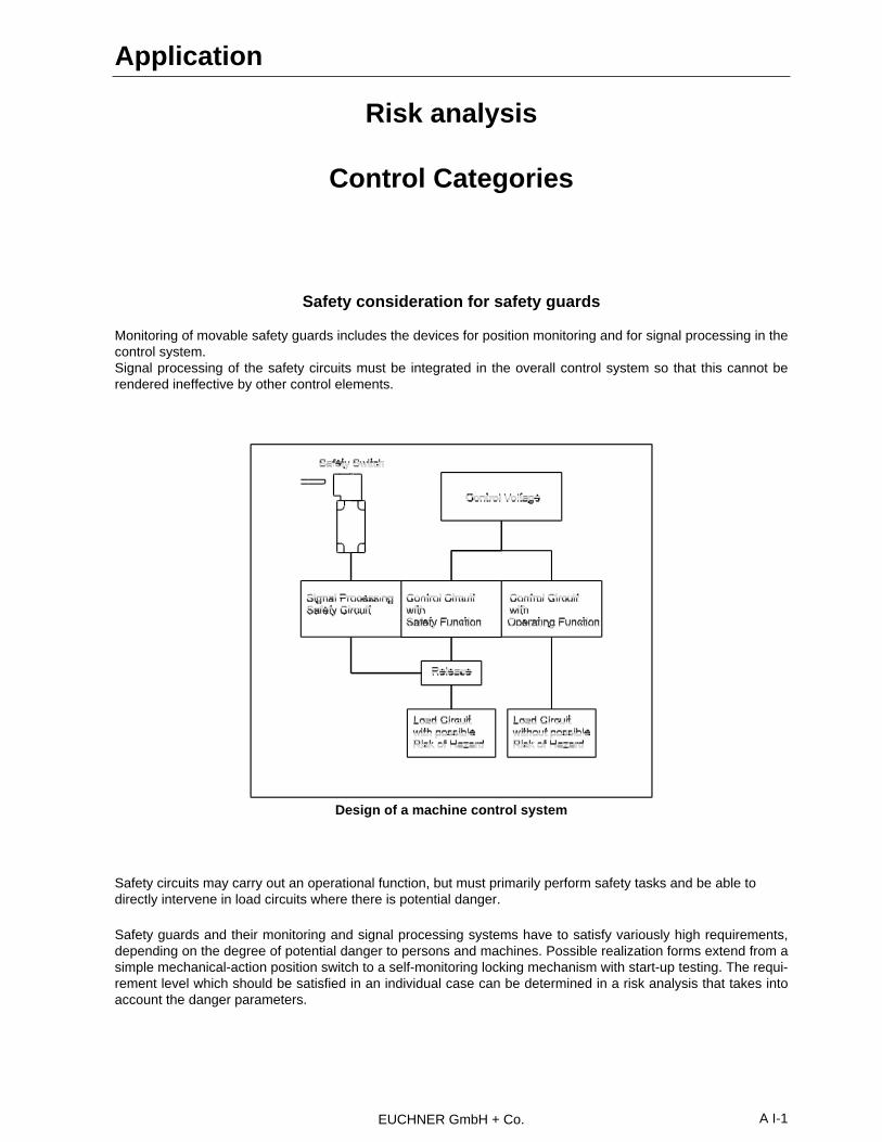
EUCHNER GmbH + Co. A I-1
Risk analysis
Control Categories
Safety consideration for safety guards
Monitoring of movable safety guards includes the devices for position monitoring and for signal processing in thecontrol system.Signal processing of the safety circuits must be integrated in the overall control system so that this cannot berendered ineffective by other control elements.
Safety circuits may carry out an operational function, but must primarily perform safety tasks and be able todirectly intervene in load circuits where there is potential danger.
Safety guards and their monitoring and signal processing systems have to satisfy variously high requirements,depending on the degree of potential danger to persons and machines. Possible realization forms extend from asimple mechanical-action position switch to a self-monitoring locking mechanism with start-up testing. The requi-rement level which should be satisfied in an individual case can be determined in a risk analysis that takes intoaccount the danger parameters.
Application
Design of a machine control system

EUCHNER GmbH + Co.A I-2
Risk estimation according to EN 954-1
The method described in this standard permits therisk involved in a particular application to be estima-ted on the basis of a few parameters which are cha-racteristic for the risk.
This risk analysis allows determination of a so-calledrequirement class from a predefined classificationscheme.
S - Severity of injury
S1 - Slight (normally reversible) injuryS2 - Serious (normally irreversible) injury including death
F - Frequency and/or exposure time to the hazard
F1 - Seldom to quite often and/or the exposure time is shortF2 - Frequent to continuous and/or the exposure time is long
P - Possibility of avoiding the hazard
P1 - Possible under specific conditionsP2 - Scarcely possible
B, 1 - 4 Categories for safety-related parts of control systems
●● Preferred categories for reference points
• Possible categories which can require additional measures
❍❍ Measures which can be over dimensioned for the relevant risk
Risk analysis
Categories
B 1 2 3 4
S1
S2
F1
F2
P1
P2
P1
P2
Starting point for
risk estimation for the
safety-related part
of the control system
Risk estimation Selection of category
Risk estimation in case of faults in the safety related parts of the control system and selection of anappropriate category

EUCHNER GmbH + Co. A I-3
Categories of safety-related Control Systems according to EN 954-1
1) The categories are not intended to be used in any given order or in any given hierarchy in respect of safety requirements.
2) The risk assessment will indicate whether the total or partial loss of the safety function(s) arising from faults is acceptable.
Control Categories
Category1) Summary of requirements System behaviour2) Main principle toachieve safety
B Safety related parts of machine control systemsand/or their protective equipment, as well as theircomponents, shall be designed, constructed,selected, assembled and combined in accordan-ce with the state of the art so they can withstandthe expected influence.
The occurrence of afault can lead to the lossof the safety function.
Mainly characterized
1 Requirements of B shall apply.
Well-tried components and well-tried safety prin-ciples shall be used.
The occurrence of afault can lead to the lossof the safety functionbut the probability ofoccurrence is lowerthan for category B.
by selection of com-ponents.
2 Requirements of B and the use of well-triedsafety principles shall apply.
Safety function shall be checked at suitable inter-vals by the machine control system.
− The occurrence of afault can lead to theloss of the safetyfunction between thechecks.
− The loss of safetyfunction is detectedby the check.
3 Requirements of B and the use of well-triedsafety principles shall apply.Safety-related parts shall be designed, so that:• a single fault in any of these parts does not
lead to the loss of the safety function; and• whenever reasonably practicable the single
fault is detected.
− When single faultoccurs the safetyfunction is alwaysperformed.
− Some but not allfaults will be de-tected.
− Accumulation of un-detected faults canlead to the loss of thesafety function.
Mainly characterized bystructure
4 Requirements of B and the use of well-triedsafety principles shall apply.Safety-related parts shall be designed, so that:• a single fault in any of these parts does not
lead to the loss of the safety function; and• the single fault is detected at or before the next
demand upon the safety function. If this is notpossible, then an accumulation of faults shallnot lead to a loss of the safety function.
− When faults occurthe safety function isalways performed.
− The faults will bedetected in time toprevent the loss ofthe safety function.

EUCHNER GmbH + Co.A II-1
ApprovalsAutomotive industry Test institutes
●● Alfa-Romeo ●● BG Berufsgenossenschaft (Germany)●● Audi ●● CSA Canadian Standards Association●● BMW ●● SAQ Svensk Anläggningsprovning Quality●● FIAT (Sweden)●● Ford ●● SUVA Schweizerische Unfallversicherungsanstalt●● General Motors (Switzerland)●● DaimlerChrysler ●● UL Underwriters Laboratories Inc. (USA)●● Opel●● Renault●● Saab Scania●● Seat●● Volkswagen●● Volvo
Safety SwitchesType Series TZ
Test institute Test certificate No. / Letter
BIA, St. Augustin TZ 1: Test certificate No. 8804882.2.TZ 2: Test certificate No. 9002380
SUVA, Switzerland Certificate No. 4092 ESwiss Power Current Inspectorate Approval No. 90,1 01377,02SAQ, Sweden Approval No. MV106-97CSA, Canada Certificate No. LR 539 42 1)
UL, USA File-No. E155795 1)1) only for cable entry (PG) but not for plug connector
Safety SwitchesType Series NZ.VZ
Test institute Test certificate No. / Letter
BIA, St. Augustin Test certificate No. 8201001.4VDE Test institute Approval No. AZ 2995-4402-4403SUVA, Switzerland Approval No. 1343SAQ, Sweden Approval No. M105-97CSA, Kanada Certificate No. LR 539 42 1)
UL, USA File-No. E155795 1)
Dutch Ministry of Social Affairs Ref. No. DGA/ETD/85/45461) only for cable entry (PG) but not for plug connector
Enabling SwitchesZS
Test institute Test certificate No. / Letter
BIA, St. Augustin ZSA test certificate No. 9100720.2ZSR test certificate No. 9301261ZSE test certificate No. 9209594
SUVA, Switzerland ZSA certificate No. 5245ZSR certificate No. 5246ZSE certificate No. 5244
SAQ, Sweden ZSA/ZSR/ZSE Approval-No. M119-94
Approvals - Safety Switches - Enabling Switches

EUCHNER GmbH + Co. A III-1
IEC 204-1EN 60204 Part 1DIN VDE 0113
Electrical equipment of industrial machinesGeneral requirements
IEC 947-5-1EN 60947DIN VDE 0660 200
Low voltage, switchgear and controlgear/positionswitches with positive opening operation
EN 775 Safety requirements for construction, equipment andoperation of robot systems
VDI 2854 Safety requirements for automated manufacturingsystems
EN 292-1EN 292-2
Safety machines, basic terms, general design prin-ciples and specifications
EN 954 Safety of machinesSafety related parts of control systemsPart 1: General design
EN 1050 Safety of machines, risk assessment
EN 1088 Interlocking devices with and without guard locking
BIA-Report 3/89 Configuration and analysis of electromechanicalsafety circuits for position monitoring of movablesafety guards
ZH1/153
Reference sheet 2/96Employers’ Liability Insurance Association forPrecision Mechanics and Electrical engineering
Selection and installation of electromechanical lock-ing facilities.Reference sheet for selection and attachment ofelectromechanical locking devices for safety functi-ons.
Sources
Laws an ordinances Available in bookshops or fromCarl Heymanns-Verlag KG, Luxemburger Str. 449,50939 Köln 41, Tel.: 0221/46 01 00,Telefax: 0221/46 01 69
Accident prevention regulations (VGB number)as well as directives, safety regulations, prin-ciples, codes of practice (ZH1/number)
Carl Heymanns-Verlag KGAddress see above
DIN-standards and VDMA standard sheets Beuth-Verlag GmbH, Burggrafenstr. 6,10787 BerlinTel.: 030/2601-1, Telefax: 030/2601-231
VDE-regulations VDE-Verlag GmbH, Bismarckstr. 33, 10625 Berlin,Tel.: 030/348001-0
BIA-ReportBerufsgenossenschaftliches Institut für Arbeitssi-cherheit - BIA, Alte Heerstraße 111, Postfach 20 43,53754 St. Augustin 2Tell. : (022 41) 2 31-02
Regulations - Standards - Recommendations

EUCHNER GmbH + Co. A III-2
United States Regulations / Standards
OSHA 1910...
ANSI B11...
ANSI/RIA R15.06-1992
Definition of a Safety System
Control Reliability
Single Component Failure
Sources
ANSI StandardsAmerican National Standards Institute
11 West 42nd St.
New York, NY 10036
Telephone: 212-642-4900
Goverment and industry regulations,
specifications and standards,
ANSI, BS, IEC, ISO, VDE, DIN
Global Engineering Documents
15 Inverness Way East
Englewood, CO 80112-5704
Telephone: 303-792-2181/800-854-7179
Fax: 303-397-7935
Code of Federal Regulations
(CFR)
Occupational Safety & Health Administration
Telephone: 212-264-3825
Regulations - Standards - Recommendations

EUCHNER GmbH + Co. A IV-1
Code for colour marking according IEC 757
Colour Abbreviation old Abbreviation newBlack sw BKBrown br BNRed rt RDOrange or OGYellow ge YEGreen gn GNBlue bl BUViolet vi VTGrey gr GYWhite ws WHPink rs PKGold - GDTurquoise tk TQSilver - SRGreen-Yellow gnge GNYE
Colour Code Table - according IEC 757

EUCHNER GmbH + Co.
For your notes