Safety Design Guidelines on Safety Approach and Design … · 3.4.2. Loss of Safety Systems for...
69
SDC-TF/2016/01 March 04, 2016 Safety Design Guidelines on Safety Approach and Design Conditions for Generation IV Sodium-cooled Fast Reactor Systems Prepared by: The Safety Design Criteria Task Force (SDC-TF) of the Generation IV International Forum
Transcript of Safety Design Guidelines on Safety Approach and Design … · 3.4.2. Loss of Safety Systems for...
SDC-TF/2016/01
March 04, 2016
Safety Design Guidelines
on
Safety Approach and Design Conditions
for
Generation IV Sodium-cooled Fast Reactor
Systems
Prepared by:
The Safety Design Criteria Task Force (SDC-TF)
of the Generation IV International Forum

2
3
DISCLAIMER This report was prepared by the Safety Design Criteria Task Force of the Generation IV International Forum (GIF). Neither GIF nor any of its members, nor any GIF member’s national government agency or employee thereof, makes any warranty, express or implied, or assumes any legal liability or responsibility for the accuracy, completeness or usefulness of any information, apparatus, product, or process disclosed, or represents that its use would not infringe privately owned rights. References herein to any specific commercial product, process or service by trade name, trademark, manufacturer, or otherwise, does not necessarily constitute or imply its endorsement, recommendation, or favouring by GIF or its members, or any agency of a GIF member’s national government. The views and opinions of authors expressed therein do not necessarily state or reflect those of GIF or its members, or any agency of a GIF member’s national government.
4
Table of Contents
1. INTRODUCTION ........................................................................................................................... 7
1.1. Background and Objectives ........................................................................................................ 7
1.2. Scope of the Safety Design Guidelines ..................................................................................... 9
2. MAIN CHARACTERISTICS OF GEN-IV SFR SYSTEMS ........................................................ 11
3. GENERAL APPROACH .............................................................................................................. 13
3.1. Design Basis and Residual Risk ................................................................................................ 13
3.1.1. Plant States for Design Basis ............................................................................................... 13
3.1.2. Practically eliminated situations and Residual Risk ............................................................ 14
3.2. General Approach to Normal Operation, AOOs and DBAs ...................................................... 15
3.3. General Approach to Design Extension Conditions .................................................................. 15
3.3.1. Application to Design .......................................................................................................... 15
3.3.2. Postulated Initiating Events for DEC .................................................................................. 16
3.3.3. Exploiting SFR Characteristics to Enhance Safety .............................................................. 17
3.4. Design Considerations for Design Extension Conditions ......................................................... 18
3.4.1. Anticipated Transient Without Scram (ATWS) ................................................................... 18
3.4.2. Loss of Safety Systems for Decay Heat Removal ............................................................... 20
3.4.3. Reactor Coolant Level Reduction ........................................................................................ 20
3.4.4. Conditions Considered for DEC Design Provisions ............................................................ 21
3.5. Practical Elimination of Accident Situations ............................................................................ 22
3.5.1. Application to Design .......................................................................................................... 22
3.5.2. Identification of Situations to be Practically Eliminated ..................................................... 23
3.5.3. Design Considerations for Situations to be Practically Eliminated ..................................... 23
3.5.4. Principles for Setting up a Demonstration of Practical Elimination .................................... 26
4. GUIDELINES FOR APPLICATION OF SAFETY DESIGN CRITERIA ................................... 28
4.1. Reactivity Issues ........................................................................................................................ 28
4.1.1. Prevention of Core Damage ................................................................................................. 28
4.1.2. Mitigation of Core Damage ................................................................................................. 32
4.2. Decay Heat Removal Issues ...................................................................................................... 37
4.2.1. Prevention of Core Uncovering ........................................................................................... 38
4.2.2. Decay Heat Removal for DBA ............................................................................................ 40
4.2.3. Decay Heat Removal for DECs ........................................................................................... 42

5
4.3. Postulated Initiating Events and Design Limits ........................................................................ 44
4.3.1. AOO and DBA ..................................................................................................................... 44
4.3.2. DEC ..................................................................................................................................... 45
4.4. Testability .................................................................................................................................. 46
4.5. Demonstration ........................................................................................................................... 47
5. CLARIFICATION AND QUANTIFICATION OF TECHNICAL POINTS CONCERNING SAFETY DESIGN CRITERIA ............................................................................................................. 49
5.1. Considerations concerning SFR Reactivity Characteristics ...................................................... 49
REFERENCE .................................................................................................................................... 51
GLOSSARY ...................................................................................................................................... 52
APPENDIX ....................................................................................................................................... 60

6
[This page is intentionally left blank.]
7
1. INTRODUCTION
1.1. Background and Objectives
Safety Design Criteria (SDC) for Generation-IV (Gen-IV) Sodium-cooled Fast Reactor (SFR) systems [1] have been developed by an SDC Task Force (TF), under the auspices of the GIF Policy Group (PG). Following approval by the PG, the SDC Report was distributed to international organisations and national regulatory bodies for review. The following needs were identified by the SDC TF members:
Development of detailed guidelines to support practical applications of SDC. Expansion of selected topics, specifically on
practical elimination (PE) of some accidents, design basis of specific components (e.g. containments).
Clarification of technical issues such as prevention and mitigation measures against sodium fire and sodium-water
reaction accidents, implications of the fact that the reactor core is not in its most reactive
configuration. In response, the PG and the GIF Senior Industrial Advisory Panel recommended the TF to:
develop guidelines for application of the SFR SDC, and pursue quantification of key criteria to demonstrate the safety advantages of Gen-IV
SFRs over current LWR designs. The objective of this report is to provide a set of guidelines to assist SFR developers in addressing the SDC in their design process for ensuring highest safety of their SFR designs. The guidelines are placed below the SDC in the hierarchy of safety standards as depicted in Figure 1 below. Initially, the guidelines will focus on specific safety concerns, such as reactivity characteristics of SFRs and heat removal issues. In the future, the guidelines will be extended by taking into account additional issues, such as fuel handling and storage. The guidelines, except Chapter 4 “Guidelines for application of safety design criteria”, provide recommendations and guidance on how to comply with the SFR SDC, which are generally applicable for Generation-IV SFR systems. Chapter 4 covers specific issues to be considered in the design of structures, systems and components (SSCs) with examples of design provisions. The TF expects that these issues and examples will be appropriately considered when applied to specific features of individual designs. Recommendations in this document are expressed as

8
‘should’ statements. It is recommended to adopt the stated measures or equivalent alternative measures.
Figure 1 Hierarchy of safety standards and position of Safety Design Criteria (SDC) & Safety
Design Guideline (SDG) [Note: ‘Technical codes & Standards’ are not provided by the GIF]

9
1.2. Scope of the Safety Design Guidelines
The primary focus of this report is to provide Safety Design Guidelines (SDG) for Gen-IV SFR systems as a technical supplement to the SDC report. The enhancement of Gen-IV SFR safety is mainly focused on improving each level of Defence-in-Depth, including the 4th level, with particular attention on the robustness of safety demonstrations (practical elimination demonstrations, independence of lines of defence). Like Generation-III Light Water Reactors (LWRs), Gen-IV SFR safety is primarily based on the use of multiple redundant engineered safety features to lower the probability of accidents and to limit the consequences of anticipated operational occurrences and design basis accidents. These safety features include independent and diverse scram systems, multiple coolant pumps and heat transport loops, decay heat removal systems, and multiple barriers against release of radioactive materials. In addition to these features, passive/inherent features for cooling and shutdown / power reduction may also play a significant role in the safety performance of Gen-IV SFRs by improving the diversity of safety systems. For very low probability Design Extension Conditions (DECs), the following two major groups of accidents merit special attention due to challenges in designing an SFR to successfully respond to these accidents without severe consequences:
1) Failure to reduce power or shut down the reactor following an off-normal initiating event, and
2) inability to remove heat from the core. To address the potential consequences of such accidents, this report focuses on providing examples of design approaches for “prevention and mitigation of severe accidents” and for “loss-of-decay heat removal capability as a situation that needs to be practically eliminated”. The SDG also include:
Clarification of key points for the design of structures, systems and components (SSCs) Quantification/qualification of sets of design conditions, and Listings with examples of “general design choices for SSCs” for Gen-IV SFR systems.
The report covers the following sections:
Chapter 1 covers “Background and Objective”, as well as “Scope of the SDG”. Chapter 2, entitled “Main Characteristics of Gen-IV SFR Systems” presents the systems
and fundamental characteristics of four current Gen-IV SFR designs.
Chapter 3, “General Approach”, explains the general definition of “Plant conditions”. This chapter also contains a “General Approach to Design Extension Conditions”,

10
describing design approaches for prevention and mitigation of accidents, postulated events and conditions, as well as application of SFR safety features. Design considerations for design extension conditions related to reactivity and decay heat removal issues are also described, as are the “Practical Elimination (PE) of accident situations”, comprising identification of the situation, design considerations, and principles of demonstration.
Chapter 4, “Guidelines for Application of SDC”, describes specific approaches for prevention and mitigation of severe accidents, related to reactivity and decay heat removal issues, with design options, postulated events and design limits, as well as testability and demonstrations.
Chapter 5 summarises SFR reactor core reactivity characteristics in relation to safety.

11
2. MAIN CHARACTERISTICS OF GEN-IV SFR SYSTEMS
A Sodium-cooled Fast Reactor (SFR) uses liquid sodium as the reactor coolant, allowing high power density with low coolant volume fraction. While the oxygen-free environment prevents corrosion, sodium reacts chemically with air and water and requires a sealed coolant system. The current plant size options range from small modular reactors, 50 to 300 MWe, to larger plants up to 1,500 MWe. The coolant outlet temperature of primary system is 500 - 550°C, which allows the use of materials developed and proven in prior fast reactor programmes. An SFR closed fuel cycle enables generation of fissile fuel and facilitates the management of minor actinides. Important safety features of SFR systems include a large margin to coolant boiling during normal operating conditions, a primary system that operates near atmospheric pressure, and an intermediate coolant loop between the radioactive sodium in the primary circuit and the power conversion system. Water/steam, nitrogen and supercritical carbon-dioxide are considered as working fluids for the power conversion system to achieve high efficiency, safety and reliability. Much of the basic technology of the SFR has been established in former fast reactor programmes, and is confirmed by the Phénix end-of-life tests in France, the restart of Monju in Japan, the lifetime extension of BN-600 and the start-up of BN-800 in Russia, as well as the start-up of the China Experimental Fast Reactor. A high level of safety can be achieved for an SFR using a combination of engineered active, passive and inherent features, which may also accommodate transients and bounding events with significant safety margins. An SFR can be arranged in a pool layout or in a compact loop layout. The following three options are considered in the GIF SFR System Research Plan, with examples provided in Figures 2-1 to 2-4 [2]:
A large size (600 to 1,500 MWe) loop-type reactor with mixed uranium-plutonium oxide fuel and potentially minor actinides, supported by a fuel cycle based on advanced aqueous processing at a central location serving a number of reactors, as shown in Figure 2-1.
An intermediate-to-large size (300 to 1,500 MWe) pool-type reactor with oxide or metal fuel, as shown in Figures 2-2 and 2-3.
A small size (50 to 150 MWe) modular pool-type reactor with metal alloy fuel, supported by a fuel cycle based on pyrometallurgical processing in facilities integrated with the reactor, as shown in Figure 2-4.

12
Figure 2-1 JSFR (Loop-configuration) Figure 2-2 ESFR(Pool-configuration )
Figure 2-3 KALIMER (Pool-configuration) Figure 2-4 SMFR(Small modular-configuration )
13
3. GENERAL APPROACH
3.1. Design Basis and Residual Risk
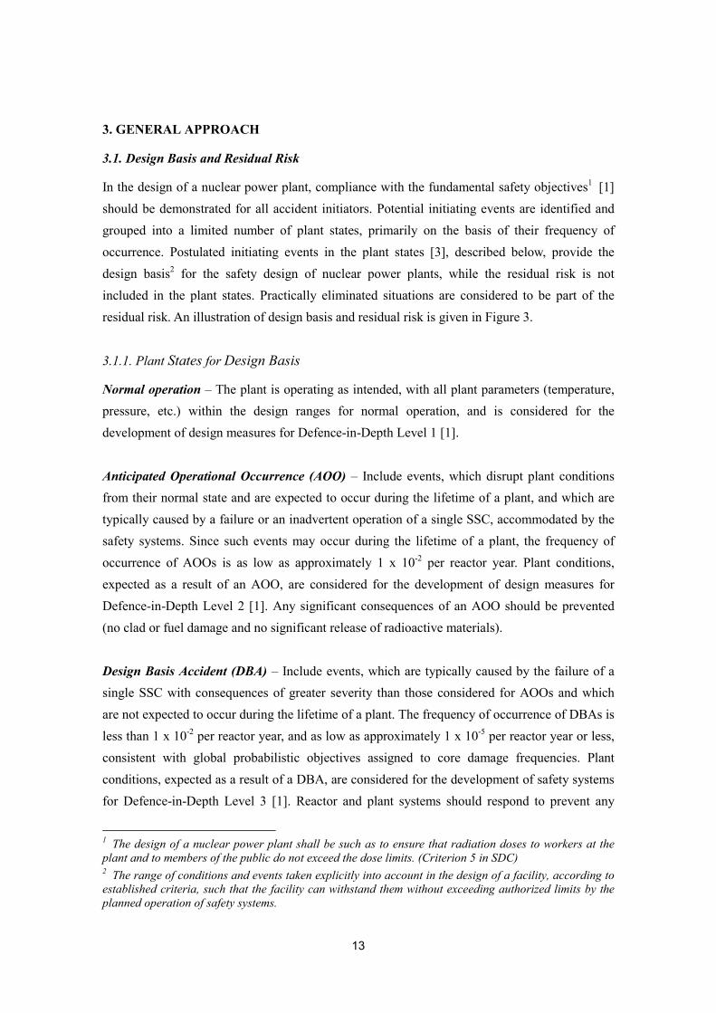
In the design of a nuclear power plant, compliance with the fundamental safety objectives1 [1] should be demonstrated for all accident initiators. Potential initiating events are identified and grouped into a limited number of plant states, primarily on the basis of their frequency of occurrence. Postulated initiating events in the plant states [3], described below, provide the design basis2 for the safety design of nuclear power plants, while the residual risk is not included in the plant states. Practically eliminated situations are considered to be part of the residual risk. An illustration of design basis and residual risk is given in Figure 3.
3.1.1. Plant States for Design Basis
Normal operation – The plant is operating as intended, with all plant parameters (temperature, pressure, etc.) within the design ranges for normal operation, and is considered for the development of design measures for Defence-in-Depth Level 1 [1].
Anticipated Operational Occurrence (AOO) – Include events, which disrupt plant conditions from their normal state and are expected to occur during the lifetime of a plant, and which are typically caused by a failure or an inadvertent operation of a single SSC, accommodated by the safety systems. Since such events may occur during the lifetime of a plant, the frequency of occurrence of AOOs is as low as approximately 1 x 10⁻² per reactor year. Plant conditions, expected as a result of an AOO, are considered for the development of design measures for Defence-in-Depth Level 2 [1]. Any significant consequences of an AOO should be prevented (no clad or fuel damage and no significant release of radioactive materials). Design Basis Accident (DBA) – Include events, which are typically caused by the failure of a single SSC with consequences of greater severity than those considered for AOOs and which are not expected to occur during the lifetime of a plant. The frequency of occurrence of DBAs is less than 1 x 10⁻² per reactor year, and as low as approximately 1 x 10⁻⁵ per reactor year or less, consistent with global probabilistic objectives assigned to core damage frequencies. Plant conditions, expected as a result of a DBA, are considered for the development of safety systems for Defence-in-Depth Level 3 [1]. Reactor and plant systems should respond to prevent any
1 The design of a nuclear power plant shall be such as to ensure that radiation doses to workers at the plant and to members of the public do not exceed the dose limits. (Criterion 5 in SDC) 2 The range of conditions and events taken explicitly into account in the design of a facility, according to established criteria, such that the facility can withstand them without exceeding authorized limits by the planned operation of safety systems.

14
significant core damage or radioactive release exceeding acceptable limits, although a limited number of fuel pin failures may occur. Design Extension Condition (DEC) – Accident conditions that are of lower probability than design basis accidents and involve the failure of more than one SSC important to safety or part of a safety system. Design extension conditions should include initiators that result in severe accident conditions and are considered for design measures to prevent or mitigate core damage. Plant conditions, expected as a result of such events, are considered for the development of design measures for Defence-in-Depth Level 4 [1].
3.1.2. Practically eliminated situations and Residual Risk
Practically eliminated situations – Specific situations, whose consequences can lead to early or large radioactive release and which cannot be managed by the design at acceptable conditions, have to be practically eliminated by implemented design measures. These situations have to be demonstrated either as physically impossible by design, or as extremely unlikely to arise with a high level of confidence. Practically eliminated situations are part of the residual risk. Residual Risk – Accidents with sufficiently low frequency due to the implementation of defencse in depth principle and not considered in the design basis.
Figure 3 Illustration of design basis and residual risk

15
3.2. General Approach to Normal Operation, AOOs and DBAs
In the new SFR designs, strong emphasis should be given to the prevention, detection and control of accident sequences [4]. An SFR must be designed to allow for stable normal operation, which requires being able to control reactor temperatures, within a small range set by the designers, possibly also by varying the reactor coolant flow using the coolant pumps, and by keeping the reactor power in balance with the demand for power from the electric grid. Reactor power is regulated using control rods, which are moved in response to the changing demand for power production, such that the steam flow rate and temperature at the turbine can be maintained. AOOs and DBAs are managed by using safety systems to shut down the reactor and to remove decay heat. These rapidly responding systems can be actuated by using a signal from the plant (i.e. the plant protection system) that detects an off-normal condition of sufficient magnitude (set by the plant designer). The goal, in case of AOOs and DBAs, is to shut down the reactor and sustain decay heat removal to keep the reactor core and system temperatures within applicable design limits.
3.3. General Approach to Design Extension Conditions
This document is focused on events that begin with a reactor under normal power operation, as the initial plant condition, excluding accident conditions associated with fuel handling and storage facilities. The following section describes the general approach for the consideration of DECs in the design and involves identifying postulated events to be included in DECs. 3.3.1. Application to Design
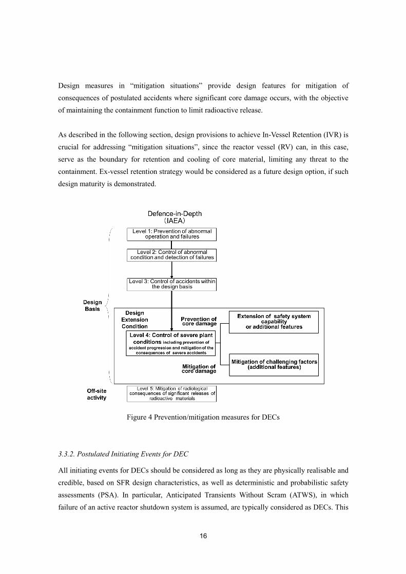
Design provisions for DECs are assigned within the fourth level of the Defence-In-Depth (DiD) as shown in Figure 4. This level includes measures for “prevention of core damage” in “prevention situations” and for “mitigation of core damage” in “mitigation situations”. The goal of design measures in “prevention of core damage” of DiD Level 4 is to provide lines of defence to prevent conditions leading to significant core damage. Design features for “prevention of core damage” in DECs deal with accident sequences that are typically caused by failure of one or more systems related to safety, such as the reactor coolant pumps, followed by failure of other safety systems needed to prevent excessive power and/or temperatures resulting from the off normal conditions of the plant. “Prevention situations” of DECs also include postulated initiating events, more severe than those in DBAs.
16
Design measures in “mitigation situations” provide design features for mitigation of consequences of postulated accidents where significant core damage occurs, with the objective of maintaining the containment function to limit radioactive release. As described in the following section, design provisions to achieve In-Vessel Retention (IVR) is crucial for addressing “mitigation situations”, since the reactor vessel (RV) can, in this case, serve as the boundary for retention and cooling of core material, limiting any threat to the containment. Ex-vessel retention strategy would be considered as a future design option, if such design maturity is demonstrated.
Figure 4 Prevention/mitigation measures for DECs 3.3.2. Postulated Initiating Events for DEC
All initiating events for DECs should be considered as long as they are physically realisable and credible, based on SFR design characteristics, as well as deterministic and probabilistic safety assessments (PSA). In particular, Anticipated Transients Without Scram (ATWS), in which failure of an active reactor shutdown system is assumed, are typically considered as DECs. This
17
includes loss of primary flow without scram, loss of main heat sink without scram, and withdrawal of the control rods resulting in a transient overpower without scram. Degradation or loss of safety systems for decay heat removal (DHR) that are not practically eliminated and reactor coolant level reductions are also considered as DECs. Design considerations related to these events are described in section 3.4. The SFR design determines which of these events are to be defined as DECs, where the frequency of occurrence and severity of the consequences are evaluated to ensure that these events are appropriate DECs. 3.3.3. Exploiting SFR Characteristics to Enhance Safety
Inherent and Passive Safety
Inherent reactivity feedback effects are obtained by using intrinsic SFR features to reduce power as the core temperature rises in accident conditions. The large temperature margin to sodium boiling (e.g. from 500-550°C in normal operation to about 900°C until boiling) of the reactor coolant provides sufficient room to use reactivity feedback due to thermal expansion of core components, as well as neutron leakage effects due to the change in coolant density. Passive shutdown systems, such as the Self-Actuated Shutdown System (SASS) [5] are also applicable. In SASS, a Curie-point magnetic alloy is utilised for automatic de-latching of control rods under high coolant temperature accident conditions, higher than for normal operating operation, but still below the coolant boiling point. A Hydraulically Suspended Rod (HSR) [6] system, where the control rods are automatically dropped into the core when the hydraulic force is reduced under accident flow reduction conditions, could also be used. In fast reactors, due to the sensitivity of the core reactivity to neutron leakage, it is also possible to consider using concepts like the Gas-Expansion Module (GEM) [7], where a decrease in core inlet pressure is exploited to increase neutron leakage under a flow reduction condition.
Decay Heat Removal (DHR)
Since an SFR is operated at nearly atmospheric pressure and at temperatures far below the coolant boiling point, coolant leakage or a pipe break does not lead to the same type of loss-of-coolant accident as postulated in an LWR, which has the potential for depressurisation, coolant boiling and loss of cooling capability. The requirements for core cooling of an SFR comprise keeping the sodium coolant level above the reactor core and the circulation of the liquid coolant to an appropriate heat sink for decay heat removal, using the normal heat transport system, a separate sodium-to-air heat exchanger, or any other system that would allow cooling of the sodium. As long as these two requirements are satisfied, significant core damage
18
can be prevented. Natural circulation of a single phase sodium coolant can be effectively utilised if an adequate difference in height is available between the core and the heat exchanger, due to the fact that sodium has a relatively large density variation with temperature. Such passive Decay Heat Removal Systems (DHRSs) can be placed in different locations, e.g. in the reactor vessel (RV) or in the primary-/secondary-coolant circuits. Alternative emergency cooling can be made available via steam generators and guard vessels (GVs) for enhancing diversity.
In-Vessel Retention (IVR)
For an SFR, in-vessel retention is a safety design strategy aimed at ensuring long-term retention of core materials inside the RV for any accident situation, including those resulting in degradation or loss of core integrity, by providing coolability of the core materials under sub-critical conditions. This is typically accomplished by providing the means to keep the core submerged under the sodium coolant and the decay heat removal paths available. Such an approach can be a key design measure to address “mitigation situations” for DECs. An ex-vessel retention strategy would be considered as a future design option, if such design maturity is demonstrated.
3.4. Design Considerations for Design Extension Conditions
3.4.1. Anticipated Transient Without Scram (ATWS)
Postulated ATWS events cause an imbalance between generated power (heat) in the reactor core and its removal from the system, either by the normal path through the power production part of the plant, or by specific heat removal systems. If adequate heat removal is not provided, substantial core degradation will occur, which may lead to severe consequences, such as large energy releases. Reliable means of maintaining the balance between heat generation and heat removal must be provided to avoid such consequences. This can be accomplished by ensuring alternate means of shutdown, including the use of inherent and/or passive reactor shutdown, as long as sufficient heat removal capability is also provided. Provisions for retention and cooling of degraded core materials are necessary to mitigate the consequences of a core damage. Provisions for ATWS can be summarised as follows.
“Prevention of core damage” Means for maintaining an acceptable balance between reactor power and heat removal capabilities should be provided to avoid core damage, given an assumed failure of the active reactor shutdown function in AOOs. These capabilities should include inherent
19
and/or passive means. In order to terminate the accident, means for reactor shutdown should be provided.
Related Criteria in the SDC Report Criterion 20: Design extension conditions Criterion 46: Reactor shutdown3.
“Mitigation of core damage”
Provisions for prevention of a large energy release that could threaten the integrity of the containment and provisions for long-term cooling of a degraded core to avoid reactor coolant boundary failure, should be made available for achieving IVR against unprotected transients with core damage.
Related Criteria in the SDC Report Criterion 20: Design extension conditions Criterion 44: Structural capability of the reactor core4 Criterion 45: Control of the reactor core5 Criterion 47: Design of reactor coolant systems6 Criterion 51: Decay heat removal system7
3 Criterion 46: Reactor shutdown
6.9. The means for shutting down the reactor shall consist of at least two diverse and independent systems. For design extension conditions, passive or inherent reactor shutdown capabilities shall be provided to prevent severe core degradation and to avoid re-criticality in the long run.
4 SDC Criterion 44: Structural capability of the reactor core For the design extension conditions, provisions shall be included to avoid re-criticality resulting in potentially large mechanical energy release during a core disruptive accident.
5 SDC Criterion 45: Control of the reactor core 6.6bis. To avoid significant mechanical energy release during a core disruptive accident, the reactor core shall be designed to have favorable neutronic, thermal, and physical characteristics, considering all reactivity feedbacks, including sodium void worth, to mitigate the consequences of such design extension conditions.
6 SDC Criterion 47: Design of reactor coolant systems 6.16bis. Components, which constitute the reactor coolant boundary, shall be designed to maintain the boundary function and to maintain a sufficient sodium inventory in the primary coolant system in case of anticipated transients without scram.
7 SDC Criterion 51: Decay heat removal system 6.19bis. Means shall be provided for the capability of core cooling under postulated plant conditions with core degradation.
20
3.4.2. Loss of Safety Systems for Decay Heat Removal
In a situation of a failed DHRS after the reactor has been shut down and the heat generation has dropped to only a few percent of the nominal power shortly, the temperature of the reactor coolant system, including the core, coolant and reactor coolant boundary, increases. The rate at which the temperature increases depends on the overall heat capacity of the system, and it may take a long time before reaching temperatures that would threaten the core or system integrity. It is therefore possible to consider recovery actions for failed DHRSs and/or to implement back up cooling measures, before reaching unacceptable temperatures for SSCs. However, if no heat sink is available the coolant boundary will eventually fail due to creep damage, leading to release of radioactive fission products and sodium vapours into the containment. Such situations should be practically eliminated by design measures for enhanced core cooling capabilities (described in Section 3.5.3). Provisions can be summarized as follows.
“Prevention of core damage” Extension of the DHRS (normally designed for DBAs) capability should be considered, and other alternative cooling provisions should be made available to prevent core damage and reactor coolant boundary failures due to overheating, given the assumed causes of DHRS failures as DECs.
Related Criterion in the SDC Report Criterion 51: Decay heat removal system8
3.4.3. Reactor Coolant Level Reduction
If the core is uncovered, following events causing a reduction of the reactor coolant level, it is impossible to avoid core melt. Depending on the course of the accident and under some
8 SDC Criterion 51: Decay heat removal system
6.19 The decay heat removal system shall be designed as follows: a) To provide diversity to the extent practicable and redundancy for reducing common cause
failures, including external events. b) To prevent freezing of the sodium coolant to avoid blockage of coolant circulation, and c) To provide detection and mitigation measures against postulated decay heat fluid leaks.
6.19bis. In design extension conditions, means for decay heat transfer shall be provided, in addition to a decay heat removal system for anticipated operational occurrence and design-basis accidents, with the conditions listed below.
a) The cooling of the reactor core is possible even under extreme external hazards and their consequences, such as long-term loss of all AC power supplies,
b) Passive mechanisms are used to the extent practicable, and c) Decay heat removal system has diversity to the extent practicable.

21
circumstances, significant radioactive material would be released into the containment atmosphere. Therefore, an uncovered core configuration should be practically eliminated by design measures (described in Section 3.5.3). Provisions can be summarised as follows.
“Prevention of core damage” Reactor Vessels (RVs) and Guard Vessels (GVs) should be designed, manufactured, installed, maintained and inspected to have the highest level of reliability in order to prevent double leakage from RVs and GVs. For a loop-type reactor, measures for ensuring a minimal primary coolant level to prevent core damage should be provided against postulated leakage from the primary loop components and piping. If double leakage from RVs and GVs cannot be practically eliminated, the situation has to be considered for implementing design provisions.
Related Criterion in the SDC Report Criterion 49: Level of reactor coolant9
3.4.4. Conditions Considered for DEC Design Provisions
When considering design provisions for the prevention of core damage and mitigation of the potential consequences of DECs, the following points need to be taken into account:
Identification of expected safety functions. Identification of accident conditions for the expected safety functions. Design to ensure performance under a postulated accident condition and, if necessary,
design to ensure performance of any required supporting system, such as plant protection and control systems, and power supplies. SSCs must maintain their integrity under the given environment.
Provision of emergency operation manuals for accident diagnosis and management actions, if necessary.
Performing safety evaluations with validated analytical codes. The evaluations will be based on best estimates to show that design limits are not exceeded.
Performing reliability analyses to review risk reduction effects against the postulated initiating event; to be complemented by deterministic analysis as needed.
9 SDC Criterion 49: Level of reactor coolant
Guard vessels and guard pipes shall be designed so as to maintain the sodium surface of the primary coolant system at a level necessary for decay heat removal in the case of a sodium leak accident in the primary coolant system. Due considerations shall be taken of a dependent failure and a common cause failure between the reactor vessel and the guard vessel, as well as between main coolant pipes and guard pipes. Provisions shall be made to reduce the amount of sodium that leaks from the primary coolant system in case of a failure of the reactor coolant boundary.
22
Consideration of the independence of the selected design provisions from other safety related SSCs.
Consideration of testability of the above mentioned provisions. Since simulation of severe plant conditions in DECs are generally not possible during normal reactor operations, an analysis based on related data, including those obtained during normal reactor operations and their extrapolation, will be used to evaluate the effectiveness of the safety functions throughout the life-time of the plant.
Probabilistic Safety Assessments (PSAs) should be implemented at the design stage to support the estimated probability of failures for accident initiators, and the adequacy of the design measures for addressing events in DECs. PSA results will also provide the means to evaluate that no particular feature or postulated initiating event makes a disproportionately large or uncertain contribution to the overall risks.
3.5. Practical Elimination of Accident Situations
This section describes the design approach for practical elimination of accident situations, examples of individual situations and considerations for design measures. 3.5.1. Application to Design
Radioactive release is subject to the practical elimination approach. The approach should be applied to any operation state of the plant, including fuel
handling and spent fuel storages. Situations, which may lead to early or large radioactive release and which cannot be
mitigated under acceptable conditions, are identified to be practically eliminated by implementation of design provisions.
The approach is intended to demonstrate that the identified situation is physically impossible by design, or that implemented provisions eliminates the situation to a residual risk with a high degree of confidence.
Practical elimination can be considered as part of a general approach and as an enhancement of the Defence-in-Depth principle. The design should restrain practical elimination to a very limited list of situations.
Related description in the SDC Report Section 2.2.4 Prevention of cliff edge effect; Severe accidents that could lead to a significant and sudden radioactive release, not reasonably manageable by design improvement, shall be practically eliminated by appropriate design provisions.
23
3.5.2. Identification of Situations to be Practically Eliminated
All potential situations which might lead to unacceptable radioactive release should be considered to identify practically eliminated situations. Some examples of practically eliminated situations are as follows:
(1) Severe events with mechanical energy release exceeding the capability of the containment Power excursions for intact core situations (during power operation)
Large gas flow through the core Large-scale core compaction Collapse of the core support structures
Note: As far as reasonably possible, severe accidents have to be managed with mitigation means, before implementing a practical elimination demonstration.
(2) Situations leading to failure of the containment with a risk of fuel damage Complete loss of the decay heat removal functions, leading to core damage and failure
of the reactor coolant boundary Core uncovering due to sodium inventory loss
(3) Fuel degradation in the fuel storage or when the containment is not functional due to maintenance (e.g. opening containment for replacement of large equipment)
Core damage without a functioning containment Spent fuel melting in the storage
Table 1 below shows the reasons for choosing the specific examples for an SFR. An example of an approach to identify situations to be practically eliminated is provided in Appendix (A). 3.5.3. Design Considerations for Situations to be Practically Eliminated
(1) Power excursions for intact core situations i) Large gas flow through the core
The primary coolant system should be designed to prevent gas entrainment from the cover gas and to limit or prevent gas accumulation in structures and components submerged in sodium. Gas release paths are necessary where gas accumulation might occur. An evaluation should be made to show that an accidental gas ingress, entrainment and transport through the core does not cause prompt criticality. Such accidental gas ingress might happen in abnormal conditions, e.g. as a consequence of a primary pump over-speed.
24
Related Criteria in the SDC Report Criterion 42bis: Plant system performance of a sodium-cooled fast reactor Criterion 45: Control of the reactor core
ii) Large-scale core compaction
Reactivity insertion, due to fuel assembly motion and deformation, should be limited to prevent core damage following any possible causes, including earthquakes. Due consideration should be taken to the fuel assembly design to prevent compaction. Adequate stiffness of the core should be ensured for each plant state, through the suitable design for the core subassemblies, core support plates and the core restraint system, if provided. The gap between the core subassemblies should be adequately limited. Control rod insertion should be assured with sufficient margin for a large earthquake. In order to maintain subcritical conditions after control rod insertion, the upward movement of the inserted control rods should be limited.
Related Criteria in the SDC Report Criterion 42bis: Plant system performance of a sodium-cooled fast reactor Criterion 44: Structural capability of the reactor core
iii) Collapse of the core support structure
The core support structure should be designed to ensure a sufficient design margin against mechanical and thermal loads. In addition, it should, during its lifetime, cope with environmental conditions, such as high radiation dose, high temperature and being submerged in sodium. Detection of potential core support deformation or failure should be provided, e.g. inspection capability by using ultrasonic detectors and monitoring plant parameters, such as flow rates and temperatures.
Related Criteria in the SDC Report Criterion 42bis: Plant system performance of a sodium-cooled fast reactor Criterion 44: Structural capability of the reactor core
(2) Complete loss of the decay heat removal function, leading to core damage and failure of the reactor coolant boundary.
For DBA, a decay heat removal system should be provided to deal with postulated initiating events typically caused by single failure of an SSC.

25
For DEC, design measures should be provided against initiating events, which are more severe than DBAs, or which originate from multiple failures of SSCs.
Proven technology, based on the design, construction and operation experience of SFRs, should be applied to the basic design of decay heat removal systems.
Extension of capabilities to deal with DECs, e.g. additional decay heat removal systems, increased capacities of heat removal, and operation with natural as well as forced circulation, should be considered. Application of mobile power sources and manual operations in case of loss of power are examples of extensions of such capabilities.
Ensuring diversity in systems is essential for improving the overall reliability. Duplication of systems does not bring the same reliability benefits. It is required to maintain heat removal functions, even under postulated severe external hazards, such as earthquakes, flooding, tsunami and missiles leading to a common cause failure.
An SFR should proactively utilise its natural circulation capability to an ultimate heat sink (atmosphere), since this can significantly contribute to improving the reliability of the heat removal capability, even under long-term loss of power supplies. Natural circulation can be used as a measure for DBAs, as well as for DECs.
Robust demonstrations of practical elimination should consider independence between safety systems for DBAs and decay heat removal capabilities for DECs. If necessary, additional independent decay heat removal systems should be installed as an ultimate measure.
It is necessary to clarify all credible factors leading to loss of decay heat removal function and to confirm that measures can be implemented to overcome all of them.
Each system, related to decay heat removal, should be able to demonstrate that it can perform its function as expected.
Related Criteria in the SDC Report Criterion 42bis: Plant system performance of a sodium-cooled fast reactor Criterion 51: Decay heat removal system
(3) Core uncovering due to sodium inventory loss
The RVs and GVs should be designed, manufactured, installed, maintained and inspected to have the highest level of reliability.
Due design considerations should be taken to prevent dependent failures and common cause failures between RVs and GVs, even under postulated severe external hazards, such as earthquakes.
In case double failures of RVs and GVs cannot be practically eliminated, provisions should be available to retain the coolant level to keep the reactor core covered.

26
Related Criteria in the SDC Report Criterion 42bis: Plant system performance of a sodium-cooled fast reactor Criterion 49: Level of reactor coolant
3.5.4. Principles for Setting up a Demonstration of Practical Elimination
Demonstrations of situations for practical elimination are made on a case-by-case basis, founded on deterministic methods, and in some cases supplemented with probabilistic studies. A good practical elimination demonstration must be convincing and independent of the methodology. There are two convincing ways for a demonstration:
Demonstrate that the situation is physically impossible by design Implement devices to make the situation extremely unlikely with a high degree of
confidence. For this, uncertainties have to be taken into account in order to reach a sufficient degree of confidence and to reinforce the robustness of the demonstration.
Deterministic demonstrations are organised by the lines of defence based on the following general principles:
Establishing a complete list of initiating events, including stress and human factors. For each event, provisions to either physically exclude the event or to make it very unlikely, should be established.
If it is not possible to physically exclude a situation, favouring provisions that enable early detection and corrective actions to avoid degradation or to make the consequences acceptable. The initiators, which may have common mode failures, reducing the effectiveness of the provisions, should be identified and additional provisions taken to avoid their consequences.
In addition, probabilistic studies are performed to ensure the expected very low frequency of occurrence.

27
Table 1 Examples of Situations to be practically eliminated for an SFR
SFR
Practically eliminated situations Reason for choice
Power excursions for intact core situations
Since the core is not in the most critical configuration, positive reactivity insertion might happen due to extreme initiating events, such as a large gas flow through the core, large-scale core compaction, or collapse of the core support structure.
Complete loss of heat removal function that could lead to core damage and failure of the reactor coolant boundary
If no heat sink is available, a coolant boundary failure will occur, either due to creep damage anywhere in the primary and secondary coolant systems, or from melt-through by degraded core materials.
Core uncovering due to sodium inventory loss
If the core becomes uncovered, it is impossible to avoid a core melt. Depending on the course of the accident and under some circumstances, significant radioactive materials would be released into the containment atmosphere.
Core damage during maintenance, or spent fuel melting in the storage
If a core damage or fuel melting occurs during maintenance (when the containment is not functional), or at the fuel storage outside the containment, significant radioactive release might happen.
28
4. GUIDELINES FOR APPLICATION OF SAFETY DESIGN CRITERIA
This chapter contains design guidelines for the application of specific criteria related to the reactivity characteristics of the reactor core, the reactor shutdown system, the containment function, and the decay heat removal system, including important design parameters, postulated events and design limits, as well as testability and safety design demonstrations. These guidelines are intended to be appropriately considered according to the specific features of individual designs and to provide designers with examples of design provisions.
4.1. Reactivity Issues
4.1.1. Prevention of Core Damage
Safety design criteria for reactor shutdown functions are defined in Criterion 46 in the SDC. The related design guidelines are presented below.
Active Reactor Shutdown
(1) SDC “The means for shutting down the reactor shall consist of at least two diverse and independent systems.”
(2) Design concept
Two diverse and independent active reactor shutdown systems, consisting of control rods, actuation mechanisms, detectors and signal processing systems.
(3) Specific functions / design considerations and design parameters
(3-1) Reactor shutdown capabilities
Specific functions / design considerations
At least one of the two reactor shutdown systems should be able to shut down the reactor and retain it in safe shutdown state10 in an AOO and a DBA without exceeding the design limits.
The reactor shutdown system, consisting of control rods, should be designed to have sufficient reactivity worth for a shutdown, even if the control rod with the maximum reactivity worth is not counted (the so-called “one rod stuck margin.”).
10 Safe shutdown state is defined as the state with the reactivity of the reactor kept to a margin below criticality under a prescribed coolant temperature condition in which interventions such as fuel reloading, periodic inspection and repair works in the reactor can be achievable.
29
Control rod insertion should be assured even in case of deformation of core components due to, for instance, irradiation or design basis earthquakes. The reactor shutdown system, which functions as reactor controller under normal operation, e.g. reactor start-up and power regulation, should also be designed so that any failure of the control function, such as control rod position change by motor drive mechanism, shouldn’t affect the reactor shutdown function.
Related consideration The reactor core should be designed to have favourable inherent safety characteristics, e.g. a negative power coefficient, to self-limit any reactor power increase in case of reactivity insertions.
Design parameters
Duration of signal transmitting and processing to actuate control rod insertion Duration of control rod insertion Reactivity worth of control rods (Reactivity characteristics of reactor core)
(3-2) Diversity and independence
Specific functions / design considerations
Two shutdown systems should be designed to have independence and diversity to the extent practicable to prevent common cause failures. Examples of design measures are:
Different structures/mechanisms for rod insertion, different designs for the control rods and their guide tubes
Physical separation of electric distribution boards and cables; isolated arrangements, divided by walls, etc.
Electrical independence of instrumentation and control systems.
Detection parameters for the reactor shutdown systems should be diverse to the extent practicable.
At least one of the two reactor shutdown systems should be designed according to a single failure criterion that applies to components of actuation mechanisms, detectors and signal processing systems.
Fail safe features, such as control rod insertion by loss of the holding function in case of electric power supply failure, should be considered.
Design parameters
Electrical and physical separation
30
Diversification of design, including detection parameters for reactor shutdown Fail safe measures
(3-3) Consideration for environmental conditions
Specific functions / design considerations
Two shutdown systems should be designed to withstand, throughout the reactor's lifetime, environmental conditions, such as irradiation, temperature, chemical effects, geometrical change, and DBAs.
Design parameters
Temperature, irradiation effects, liquid sodium environmental conditions, cover gas plenum with sodium aerosols.
Reactor Shutdown for DECs
(1) SDC “For design extension conditions, passive or inherent reactor shutdown capabilities shall be provided to prevent severe core degradation and to avoid re-criticality in the long run.”
(2) Design concept
Passive reactor shutdown capabilities; several different mechanisms, including those responding to coolant temperature increase or coolant hydraulic force change.
Inherent reactor power reduction in balance with heat removal capabilities due to negative reactivity feedback from Doppler effect, axial and radial expansion of core and structure, and even sodium expansion effects, if designed accordingly.
(3) Specific functions / design considerations and design parameters (3-1) Capability of passive shutdown or inherent power reduction mechanisms
Specific functions / design considerations
Passive reactor shutdown and/or inherent power reduction capabilities should be provided in case of an AOO with a failure of the active reactor shutdown systems, to avoid exceeding the design limits for DECs. This should be achieved by a passive shutdown mechanism or inherent reactivity feedback, or their combination.
1) Passive shutdown mechanisms should be designed to provide sufficient negative reactivity within an allowable time and to be activated and operated in direct
31
response to natural phenomena (such as increased coolant temperature or reduced coolant pressure) without any active signals, activation mechanisms or power source.
2) Inherent reactivity feedback, based on the total power coefficient, isothermal temperature coefficient and power/flow coefficient, should be negative to reduce the core power at elevated temperatures in balance with available heat rejection capacities during an ATWS. Complementary reactor shutdown measures should be provided in order to make the reactor core subcritical in the long term.
Design parameters
Passive shutdown mechanisms: Parameter related to the reactor condition to which the passive shutdown mechanisms respond, e.g. coolant temperature at the reactor core outlet, reactor coolant flow etc. Activation point of the parameter, response time, amount of reactivity.
Inherent reactivity feedback: Total power coefficient, isothermal temperature and power/flow coefficients, reactivity feedback mechanisms, such as axial and radial core expansions at elevated temperatures, and thermal expansion of the control rod driveline. Amount and timing of the introduction of favourable feedback should be appropriate to cause power reduction and prevent excessive temperature rise in the reactor.
(3-2) Prevention of common cause failures for passive reactor shutdown mechanisms
Specific functions / design considerations
Passive reactor shutdown mechanisms should not be affected by any failures of the active systems. Insertion of control rod type absorbers should be ensured even with static or dynamic core deformation caused by postulated events, such as earthquakes and environmental conditions, including irradiation. Implementation of such devices should not induce additional causes of deviation from normal operation, such as frequent spurious activation.
Design parameters
Acceptable limits of core deformation for ensuring unforced insertion of absorbers
(3-3) Long term reactor shutdown Specific functions / design considerations Measures to achieve and maintain a safe shutdown state and to monitor the plant conditions should be provided in case of failure of the active shutdown systems.
Design parameters Reactivity needed for safe shutdown
32
Parameters for monitoring the reactor condition after an accident
(3-4) Consideration for environmental conditions
Specific functions / design considerations
Passive shutdown mechanisms should be designed to withstand, throughout the lifetime of the reactor, environmental conditions, such as irradiation, temperature, chemical effects and geometrical change, as well as DBAs/DECs.
Reactivity effects of inherent reactor power reduction capabilities should be assured throughout the lifetime of the reactor, considering environmental conditions, such as irradiation, temperature, chemical effects and geometrical changes.
Design parameters
Temperature, irradiation effects, liquid sodium environmental conditions 4.1.2. Mitigation of Core Damage
The mitigation functions of core damage are defined in the Criteria 44, 45, 47 and 51 in the SDC for GIF SFRs. The related design guidelines are presented below.
Design measures against core damage from unprotected transients should be implemented for the following accident phases, according to the progression of a core damage:
Initiating phase; accident phase from intact state up to inter-subassembly material motion onset, i.e. subassembly duct failure
Transition phase; accident phase after initiating phase up to the establishment of stable cooling conditions
Post accident heat removal; stable cooling condition for a long term
Mitigation in Initiating Phase
(1) SDC “To avoid significant mechanical energy release during a core disruptive accident, the reactor core shall be designed to have favourable neutronics, thermal, and physical characteristics, considering all reactivity feedbacks, including sodium void worth, to mitigate the consequences of such design extension conditions.”
33
(2) Design concept Various core designs with different output power, different fuel material properties, i.e. oxide and metal. A common core geometry consists of fuel subassemblies containing the fuel pins in ducts of hexagonal cross-sections, typically referred to as subassembly ducts or hex-cans.
(3) Specific functions / design considerations and design parameters
(3-1) Limiting the total reactivity during unprotected transients
Specific functions / design considerations
Core reactivity characteristics should be designed so as to prevent prompt criticality, i.e.
ρnet < 1$ during the initiating phase of unprotected transients. Positive reactivity effects,
such as sodium boiling, should be limited so that negative reactivity effects e.g. Doppler
effect, fuel expansion and failed fuel dispersion are sufficient to counteract the positive
reactivity effects. Design parameters, such as sodium volume fraction, core height and
other geometric parameters, should be properly chosen based on the effects of sodium void
worth during transients.
Design parameters
Core reactivity characteristics (sodium void reactivity, Doppler effect, fuel axial expansion, core radial expansion, control-rod driveline expansion, etc.)
Sodium volume fraction and core height and geometry (e.g. heterogeneous arrangements, sodium plenum)
(3-2) Facilitating fuel reactivity effects
Specific functions / design considerations
Core design parameters, such as core height, should be properly chosen to obtain effective negative feedback due to failed fuel dispersion. Fuel reactivity feedback is dependent on the choice of fuel type for the reactor. The effects should be appropriately included in transient analysis of an accident.
Design parameters
Choice of fuel type, core height
34
Mitigation in Transition Phase
(1) SDC “For the design extension conditions, provisions shall be included to avoid re-criticality resulting in potentially large mechanical energy release during a core disruptive accident.”
(2) Design concept
Various concepts are possible depending on design and fuel characteristics (3) Specific functions / design considerations and design parameters
(3-1) Limiting the total reactivity during unprotected transients
Specific functions / design considerations
In the course of a core degradation during unprotected transients, measures should be provided to prevent prompt criticality, potentially leading to large mechanical energy release. For this purpose, design measures, such as facilitating molten fuel discharge outside the core, neutron absorber added to the core, and core cooling to prevent failure progression, i.e. early termination, should be taken. These measures should include consideration of using favourable inherent phenomena occurring in the course of a core degradation.
The design of a molten fuel discharge path, if present, should: a) prevent blockage due to freezing of molten relocated cladding and/or fuel, b) be accessible prior to formation of large amounts of molten fuel, and c) have enough capacity for timely discharge of molten fuel.
Design parameters
Choice of fuel type, core geometry, fuel fissile density, fuel mass amount of core, core material properties;
For molten fuel discharge, if present, the required geometry, e.g. diameter, length, and material properties of discharge path.
(3-2) Establishment of a stable cooling condition
Specific functions / design considerations
Measures should be provided to establish a stable cooling condition of a degraded core. Due consideration should be taken to the coolability of the remaining fuel inside the core region and any relocated molten core materials. Prompt criticality, potentially leading to large mechanical energy release, should be prevented during the relocation process.

35
Design parameters
Molten fuel relocation characteristics Molten fuel relocation path Coolant flow and re-entry paths to the core.
Prevention of Reactor Coolant Boundary Failures
(1) SDC “Components, which constitute the reactor coolant boundary, shall be designed to maintain the boundary function and to maintain a sufficient sodium inventory in the primary coolant system in case of anticipated transients without scram.”
(2) Design concept
Prevention of reactor coolant boundary failures against mechanical load. (Countermeasures depend on the reactor structure design)
(3) Specific functions / design considerations and design parameters
(3-1) Prevention of reactor coolant boundary failures following mechanical loads
Specific functions / design considerations
The reactor coolant boundary should maintain its boundary function following pressure loads, including any loads induced by fuel-coolant interaction (FCI).
Design parameters
Inlet and/or outlet design of core assemblies, plena geometry, structural design of reactor coolant boundary components, material strength.
(3-2) Prevention and mitigation of sodium ejection from a reactor cover gas boundary due to mechanical loads
Specific functions / design considerations
Reactor cover gas boundary components should withstand pressure loads to prevent sodium ejection into the containment, including any loads induced by FCI. Design measures, such as strengthened seals of plug structures, including rotating plugs for fuel handling, should be considered.
Mitigation provisions against sodium ejection should also be implemented as needed.
Design parameters
Structural design of reactor cover gas boundary components, material strength
36
(3-3) Prevention of over pressure
Specific functions / design considerations
Measures should be provided to cope with temperature and pressure increases due to heat generation and accumulation of fission gases, released from a degraded core.
Design parameters
Installation of pressure relief devices, such as safety relief valves at the reactor cover gas boundary
Post Accident Heat Removal
(1) SDC “Means shall be provided for the capability of core cooling under postulated plant conditions with core degradation.”
(2) Design concept
Retention and cooling of a degraded core Depending on reactor core characteristics, perform the retention function with an existing component or structure, or a dedicated structure, e.g. core catcher.
(3) Specific functions / design considerations and design parameters
(3-1) Retention of a degraded core
Specific functions / design considerations
Measures should be provided to retain degraded core materials to facilitate post accident heat removal. Re-criticality of a retained degraded core should be prevented during the post-accident heat removal phase. The retention structure should resist the thermal load from a degraded core, as well as mechanical loads, including any loads from FCIs.
Design parameters
Design of any structure intended to retain degraded core materials, including the core inlet plenum, core support structure (form, strength), material strength characteristics;
Coolability and re-criticality of degraded core materials; Fuel retention capacities for such structures; Characteristics and relocation of degraded core materials.

37
(3-2) Ensuring a coolant circulation path and heat sink
Specific functions / design considerations
A coolant flow path and heat sink should be available for cooling of degraded core materials.
Natural circulation capability should be incorporated.
Structures and components that form the flow paths should maintain their functions against adverse effects, such as mechanical loads from FCI and blockage by dispersed fuel debris.
Design parameters
Reactor cooling system design (coolant flow path, heat sink and natural circulation capability)
Material strength to resist FCI loads (3-3) Protection of a degraded core retention structure
Specific functions / design considerations
For IVR, the reactor structure should facilitate molten fuel dispersion and solidification in the presence of adequate heat removal capability to prevent or mitigate erosion of any structure intended to retain the degraded core materials caused by molten fuel.
Depending on the characteristics of the degraded core materials, preventive measures against erosion, such as installing protective layers on core retention structures, should be considered.
Design parameters
For IVR, sodium mass and depth in the lower plenum of the RV above the core catcher or retention place
Material property of protection layers for the core catcher or retention place, if necessary.
4.2. Decay Heat Removal Issues
Decay heat removal functions are defined in Criteria 49 and 51 in the SDC for GIF SFR. The related design guidelines are presented below.

38
4.2.1. Prevention of Core Uncovering
(1) SDC “Guard vessels and guard pipes shall be designed so as to maintain the sodium surface of the primary coolant system at a level necessary for decay heat removal in the case of a sodium leak accident in the primary coolant system. Due considerations shall be taken of a dependent failure and a common cause failure between the reactor vessel and the guard vessel, as well as between main coolant pipes and guard pipes. Provisions shall be made to reduce the amount of sodium that leaks from the primary coolant system in case of a failure of the reactor coolant boundary.”
(2) Design concept
Guard vessel, Guard pipes (option for loop type)
(3) Specific functions / design considerations and design parameters
(3-1) Guard vessel
Specific functions / design considerations
A Guard Vessel (GV) should be installed to enclose the Reactor Vessel (RV) so that the reactor sodium level can be maintained in the RV following a sodium leak. The gap volume between the RV and the GV should be limited, so that the sodium surface level inside the RV should, during a safe shutdown state, always be above the design limit level for sodium circulation (EsL; emergency sodium level).
Design parameters
Gap/volume between the reactor coolant boundary and the GV (guard pipe as loop type option)
EsL in RV
(3-2) Prevention of double failure of the RV and the GV
Specific functions / design considerations
In order to substantiate the practical elimination of core uncovering, the conditions for preventing double failure of the RV and the GV are given as follows.
Ensure the reliability The RVs and GVs should be designed, manufactured, installed, maintained and inspected to have the highest level of reliability.
39
Prevention of GV failure being subordinated to RV failure: The GV should withstand thermal loads due to a sodium leak from the RV. The GV should withstand mechanical loads from all possible causes, such as
earthquakes, while retaining leaked sodium for a long time. The GV should withstand any interference with a failed RV (even considering
thermal expansion, vibration, etc.).
Prevention of common cause failure between RV and GV: The design should separate the support structures of the RV and GV to the
extent practicable, or prevent failures of common parts of the support structures. The design should prevent common cause defects in manufacturing The design should ensure sufficient margins against internal/external hazards,
including earthquakes.
In case a double failure of the RV and GV cannot be practically eliminated, provisions should be made to retain the coolant level, i.e. limitation of the free volume in the reactor pit, to mitigate sodium chemical reaction inside the pit and to provide thermal insulation of the reactor building.
Design parameters
Design margin of the RV and GV Independency of the RV and GV Inspectability of the RV and GV Free volume in the reactor pit (In case a double failure of the RV and GV cannot be
practically eliminated)
(3-3) Measures against sodium leaks from the primary loops (Note: only required for loop-type designs)
Specific functions / design considerations
Measures, such as installing guard pipes and GVs, as well as piping arrangements above the coolant surface level, should be provided for ensuring core cooling and for reducing the effects of sodium leaks from any primary loop pipe or component. Design basis leaks should be determined with due consideration taken to the application of the Leak Before Break (LBB) concept.
For DECs, if guard pipes are installed to maintain the coolant level, they should be designed to withstand loads associated with large breaks of the primary pipes. In order to prevent core damage under severe leak conditions, such as multiple leaks in the primary loops, decay heat removal measures should be provided, e.g. enabling an in-vessel cooler

40
to be operable in case of low sodium levels without coolant circulation in the primary coolant loops.
Design parameters
Arrangement of the primary coolant system (vertical position of primary pipes), sodium quantity
4.2.2. Decay Heat Removal for DBA
(1) SDC “The decay heat removal system shall be designed as follows:
(a) To provide diversity to the extent practicable and redundancy for reducing common cause failures, including external events.
(b) To prevent freezing of the sodium coolant to avoid blockage of coolant circulation, and (c) To provide detection and mitigation measures against postulated decay heat fluid
leaks.” (2) Design concept
Various options for system configuration, number of sub-systems (DRACS, PRACS, IRACS,
RVACS, SGAHRS etc.). A secondary sodium loop connected to an air cooler is a typical
DBA countermeasure.
DRACS; Direct Reactor Auxiliary Cooling System
PRACS; Primary Reactor Auxiliary Cooling System
IRACS; Intermediate Reactor Auxiliary Cooling System
RVACS; Reactor Vessel Auxiliary Cooling System
SGAHRS; Steam Generator Auxiliary Heat Removal System (3) Specific functions / design considerations and design parameters
(3-1) Basic capability of a DHRS
Specific functions / design considerations
In AOOs and DBAs, a Decay Heat Removal System (DHRS) should be able to cool the reactor core immediately after reactor shutdown and for as long as needed time. The system configuration and heat removal capacity of DHRSs, as well as transient characteristics, such as flow coastdown of the primary pumps, should be set not to exceed design limits of AOOs and DBAs, as discussed in Section 4.3, assuming a single failure.

41
Design parameters
Heat removal capacity of DBA measures Decay heat characteristics Pump coastdown Primary coolant system heat capacity
(3-2) Ensuring reliability of a DHRS
Specific functions / design considerations
In order to avoid a common cause failure in case of DBAs, including external events, redundancy and diversity should be adequately provided. DHRSs should be designed to have redundancy for ensuring sufficient core cooling capacity against AOOs and DBAs, considering loss of off-site power and single failure of components. For instance, three systems at 100% of the capacity required for decay heat removal, or four systems at 50% capacity, would be provided, considering one system failure as an initiating event and a single failure in another system, depending on the design.
Diversity in the system configuration and/or operation mode (forced circulation and natural circulation), as well as physical separation, should be introduced.
Design parameters
Redundancy (number of subsystems and their heat removal capacity) Diversity (system level, component level, mechanism level (i.e., forced/natural
circulation)) Emergency power supply system, if required (the capacity and the activation time)
(3-3) Prevention of coolant freezing
Specific functions / design considerations
In order to prevent sodium (or other types of coolant such as NaK) freezing in DHRSs, design measures, such as keeping a minimum flow rate, providing an electric heater, or hot gas blow heating, should be provided. To prevent freezing in the air coolers, design measures should be provided, e.g. keeping forced circulation in the sodium circuits and independent control of subsystems for prevention of common cause failures due to malfunction of the air flow regulators and blowers.
Design parameters
Operating temperature (standby temperature) Heat exchange characteristics of air cooler (control characteristics)

42
(3-4) Measures against sodium leaks
Specific functions / design considerations
Design provisions should be made for the detection of sodium (or other types of coolant such as NaK) leaks, e.g. aerosol and contact type detectors, and for mitigation of the effects of chemical reactions between sodium and air or water, e.g. guard pipes or enclosures, sodium drain systems.
Design parameters
Design measures for detection and mitigation 4.2.3. Decay Heat Removal for DECs
(1) SDC “In design extension conditions, means for decay heat transfer shall be provided, in addition to a decay heat removal system for anticipated operational occurrence and design-basis accidents, with the conditions listed below.
(a) The cooling of the reactor core is possible even under extreme external hazards and their consequences, such as long-term loss of all AC power supplies,
(b) Passive mechanisms are used to the extent practicable, and (c) Decay heat removal system has diversity to the extent practicable.”
(2) Design concept
Functional extension of the design measures dedicated to AOOs and DBAs to cope with DECs. Providing alternative cooling measures, in addition to the measures for DBAs.
(3) Specific functions / design considerations and design parameters
(3-1) Enhancement of decay heat removal capabilities
Specific functions / design considerations
The capability of the design measures, dedicated to AOOs and DBAs, should be extended to cope with more severe postulated initiating events than DBAs, taking potential internal and external hazards, such as missiles, into account.
Accident management provisions should be made so that recovery operations can be performed in case of failure of the DBA provisions (e.g. manual operation of air cooler dampers, utilisation of mobile power sources).

43
Design parameters
Heat removal capacity in DECs Decay heat characteristics Primary coolant system heat capacity
(3-2) Alternative cooling measures
Specific functions / design considerations
The heat removal capacity of alternative decay heat removal measures for DECs should be set so that the reactor systems do not exceed the design limits for DECs, as discussed in Section 4.3. The measures should be independent from those for AOOs and DBAs. Start-up and operation procedures should be established in line with diagnostic processes, even under severe plant conditions, such as after failure of DBA provisions.
Design parameters
Heat removal capacity Decay heat characteristics Primary coolant system heat capacity Diversity and independence to the AOO and DBA measures
(3-3) Natural circulation capability
Specific functions / design considerations
In order to enhance the reliability of the decay heat removal function and to maintain the function under long-term loss of all AC power, natural circulation capability should be properly incorporated into the whole decay heat removal system, which consists of systems dedicated to AOOs and DBAs, and alternative ones for DECs. The reactor cooling system should be designed to have an adequate height difference between core and heat exchangers, and an adequate pressure drop for enhancing natural circulation capabilities of the coolant. Use of active devices, as well as instrumentation and control, should be limited, and should have sufficient grace time in both automatic and manual operation modes.
Design parameters
Height difference between core and heat exchanger to ultimate heat sink Pressure drop Natural circulation start-up characteristics
44
(3-4) Enhancement of the reliability of the decay heat removal function
Specific functions / design considerations
In order to avoid a common cause failure in case of DECs, in addition to AOOs and DBAs or as a consequence of external events, diversity and independence of the decay heat removal measures should be adequately assured for both AOOs/DBAs and DECs. Examples of potential common cause failures are earthquakes, aircraft crashes, flooding, sodium freezing in air coolers, sodium fires on the reactor roof, and loss of all AC power. Diversity in system configurations, components, working fluids (sodium, gas), operational principles (forced circulation and natural circulation), and physical separations, should be adequately introduced.
Design parameters
Diversity and independence of decay heat removal measures
4.3. Postulated Initiating Events and Design Limits
4.3.1. AOO and DBA
(1) Typical postulated initiating events Postulated initiating events under AOOs and DBAs include those that challenge the fundamental safety functions of the reactor, such as reactivity control, core heat removal, and the containment of radioactive materials. Examples of postulated initiating events for AOOs and DBAs for an SFR are provided in Appendix (B).
(2) Design limits Multiple barriers against the release of radioactivity consist of fuel elements, fuel cladding, reactor coolant and cover gas boundaries, guard vessels (and pipes in a loop configuration), and containments. These functions need to be maintained for AOOs. For DBAs, the reactor core geometry is preserved and should be coolable, and the reactor coolant boundary, cover gas boundary, and containment should uphold their barrier functions.
Typical indices for design limits of the reactor core are the maximum temperatures of the fuel, cladding, and coolant. Coolant boiling should be prevented to maintain the cooling of the reactor core, and to limit its contribution to the net reactivity.
Cladding damage during normal operation and AOOs should be limited so that specified acceptable fuel design limits are not exceeded.
45
The integrity of the reactor coolant boundary should be maintained during abnormal temperature increases by limiting the maximum coolant temperature and the time at that temperature.
Typical indices for the containment are the containment temperature and internal pressure.
Concerning release of radioactive materials, the potential public radiation exposure dose should be limited according to the criteria for operational states and accident conditions.
4.3.2. DEC
Core damage prevention under DECs
(1) Typical postulated initiating events
Typical postulated initiating events include ATWS that require other means of controlling or reducing the reactor power, such as passive shutdown or provisions for favourable inherent reactivity feedback. Postulated ATWSs, associated with failures of active reactor shutdown systems, comprise: Loss of Flow (LOF), e.g. loss of power in all the primary pumps, Transient Over Power (TOP), e.g. uncontrolled withdrawal of a control rod, and Loss of Heat Sink (LOHS), e.g. loss of main heat removal system typically via the secondary coolant system or the water-steam system.
Typical events, challenging the “reactor core heat removal” safety function, are: multiple failures in the coolant system or multiple failures of the decay heat removal function, which might result in a reduction of the reactor coolant level or loss of the safety systems for decay heat removal. For these events, core degradation, due to core uncovering or complete loss of decay heat removal capabilities, should be practically eliminated by design measures.
(2) Design limits
As for the reactor core, coolant boiling and significant cladding tube failures should be prevented. Fuel melting should be averted or limited to maintain a coolable geometry.
As for the coolant boundary, creep failure caused by a temperature increase should be prevented. Hence, temperature increases and duration of the events should be adequately limited.
Containment failures should be avoided, i.e. temperature and pressure limits should not be exceeded.
Any release of radioactive materials from the containment should be limited and should not exceed acceptable regulatory dose limits to achieve “elimination of the need for off-site
46
emergency response” for these events [8]. This does not mean that the need for off-site emergency response is eliminated in general.
Mitigation of consequences of core damage under DECs
(1) Typical postulated initiating events
Initiating events resulting in core degradation from unprotected transients, are representative of DECs with core melt. If inherent power reduction capabilities are insufficient, core degradation can occur, and analyses should include considering the uncertainty of individual reactivity feedback effects.
The potential for propagation of damage from local fuel failures should be considered as a core degradation mode and different from that of core damage from unprotected transients.
Provisions for achieving IVR should mitigate challenges to the containment structure from either type of core degradation modes.
(2) Design limits
Severe mechanical energy release, resulting in a reactor coolant boundary failure, should be prevented for unprotected transients that may lead to core degradation. Possible indices are: the limitation of the fuel temperature or the prevention of prompt criticality, i.e. maximum net reactivity should be less than one dollar.
To prevent coolant boundary failures, the strain on the RV should be limited so that the failure won't occur during a dynamic load. In addition, creep damage, due to thermal stress at an elevated temperature, should be prevented.
Containment failures should be avoided, i.e. the temperature and pressure should not exceed specified limits. If hydrogen generation has to be considered, its concentration should be controlled to avoid reaching deflagration and detonation limits.
Release of radioactive materials should not exceed the regulatory limits for the public radiation exposure dose that initiates off-site response.
4.4. Testability
The safety functions of SSCs mentioned in 4.1 and 4.2 should regularly be inspected and tested throughout the plant's lifetime according to their safety classifications. Examples of tests and inspections to be performed during the plant's lifetime are given below.
Particular attention should be paid to the following aspects:
47
integrity of the barriers between radioactive materials and the environment (such as fuel cladding, the reactor coolant boundary and the containment);
availability of safety systems, such as protection systems, safety actuation systems and safety system support features;
availability of items, whose failure could adversely affect safety; accessibility and operability for monitoring and inspection of components under
submerged in sodium coolant.
(1) Reactivity feedback
Measurement of reactivity feedback during start-up to verify both sign and magnitude for normal operation and accidents
(2) Reactor shutdown
Functional tests of control rod positions and insertion times to ensure that the tested system or component is capable of performing its design function
(3) Decay heat removal
Functional tests of active components, such as pumps and blowers Confirmation of natural circulation heat removal capabilities, for instance, by checking
temperature and flow rate changes from a safe shutdown state in case of termination of forced convection. This could be done as a performance test in the commissioning stage or pre-start-up phase in service.
4.5. Demonstration
The effectiveness of the safety functions of SSCs, mentioned in 4.1 and 4.2, should be demonstrated according to their safety classification before starting any power operation of a nuclear power plant. Examples of information required for the safety demonstration are given in this section.
For DBAs and DECs without core damage, experiments, using scale models of the actual SSCs or actual reactor tests during commissioning stage, can be possible and useful for the safety demonstration.
For DECs with core damage, direct performance demonstration on the actual reactor is impossible. Thus, numerical simulations have an important role. Various uncertainty factors should be considered for the demonstration. In addition, experiments should be set up to validate the analytical tools and to understand the basic phenomena having a bearing on the accident analysis.
(1) Passive shutdown mechanism (example for SASS)

48
Material tests: understanding physical properties of sensing alloys (Curie point temperature, thermal aging and irradiation effect), productivity.
Component tests: control rod insertion performance by model tests, transient response tests, thermal hydraulic tests at the reactor outlet by scale models.
Reactor tests: stability of the in-vessel holding force, operability and material tests. Development of analytical methods for design and evaluation. Validation of analytical methods based on above-mentioned experiments. Evaluation of the core damage frequency from reactor shutdown failures using PSA.
(2) Decay heat removal by natural circulation
Validation of analytical models by water and sodium tests and applying the results to the evaluation of the reactor case.
The performance of the actual plant should be confirmed during the performance test phase.
Evaluation of the core damage frequency from loss of heat removal using PSA.
(3) Mitigation of core damage
Development of analytical models, combining fuel pin failures and relocations with reactivity feedback; In-pile experiments for fuel pin failures and relocation behaviours.
49
5. CLARIFICATION AND QUANTIFICATION OF TECHNICAL POINTS CONCERNING SAFETY DESIGN CRITERIA
In the course of the international reviews of the “SDC Phase 1 Report”, a request was made for a technical clarification of the “sodium void reactivity in the fast reactor core reactivity characteristics” to be included in the SDG. In general, the idea and design concept of a so-called “negative sodium void reactivity reactor core” has been proposed and examined from many angles during the some half-century long SFR development history.
This chapter summarises the general reactivity characteristics of an SFR and contains concluding remarks on the sodium void reactivity in relation to SFR safety, emphasising that it is the overall reactivity feedback that is important and not any single part, such as sodium void. In addition, integrated transient analysis is required to determine if the sodium void of the design is acceptable or not since the entire core typically does not void during a postulated transient, but sodium voiding is usually predicted to initially occur locally with a much lower reactivity effect. Positive sodium void is not necessarily a problem, nor is negative sodium void necessarily a solution.
5.1. Considerations concerning SFR Reactivity Characteristics
Normal operation and DBAs Various reactivity coefficients, such as the Doppler coefficient, sodium coolant temperature coefficient and cladding temperature coefficient, exist for the respective core constituents in relation to changes in temperature and geometry. The core characteristics are commonly represented by an integral effect from these reactivity coefficients, e.g. the total power coefficient, the isothermal temperature coefficient and the power/flow coefficient. For normal operations, these integral coefficients are required to have certain characteristics, such as a negative power coefficient, to allow stable operation and reliable control of the reactor. Within the AOO and DBA domains, a reactor shutdown by the reactor protection system determines the outcome; therefore, there are no definite additional requirements on the reactivity feedback, as long as the design limits are not exceeded.
The coolant temperature coefficient is defined as the rate of reactivity change due to the coolant density change with temperature. It is also related to the void coefficient, as the liquid phase turns to vapour phase at elevated temperatures (in excess of around 900C for a sodium coolant). In general, a core with a large coolant temperature coefficient has also a large sodium void coefficient and a large overall sodium void worth. Usually, all reactor cores have regions of positive void worth (the interior) and negative void worth (the periphery). The overall sodium void worth can be positive for large cores, and can be reduced to zero or become negative for
50
small cores, due to the larger neutron leakage. For DBAs, sodium void worth is not particularly relevant, since coolant boiling is not expected to occur. Core damage prevention under DECs As long as boiling of the sodium coolant is prevented, any effect of sodium void worth is not relevant. Although the sodium coolant temperature coefficient might be positive, the importance of various reactivity coefficients comes into play during ATWS events. No additional requirements are specified for the integral reactivity coefficients, on the condition that core damage is prevented by a passive shutdown device/measure during ATWS events. When an inherent reactivity feedback approach is used, instead of a passive shutdown device/measure, the total power coefficient, isothermal temperature coefficient and power/flow coefficient should all be sufficiently negative and respond in a timely manner to quickly achieve sub-criticality during ATWS events.
In a loss-of-flow transient, with failure of the reactor protection system (i.e. without scram), the coolant temperature and/or void reactivity could pose a challenge, depending on their magnitude and timing, since they can be quite positive (can add reactivity to the core when the coolant temperature rises). Therefore, the coolant temperature coefficient should be limited within a range where other reactivity feedback effects (such as control rod expansion and/or core expansion) can compensate. In this context, the positivity of the sodium void worth plays a minor role. The reactor core damage should be prevented by applying a passive shutdown device/measure or by reliance on inherent safety with net negative reactivity feedback at elevated temperatures. Mitigation of consequences of core damage under DECs A coolant phase change and a material relocation of a degraded core can have significant reactivity consequences, both favourable and unfavourable, depending on design choices. When a core damage and material relocation occur, prompt criticality should be avoided in order to prevent large mechanical energy release. In particular, the maximum net reactivity during an initiating phase should be limited below 1 dollar. Positive reactivity effects, such as sodium boiling, should be limited considering e.g. spatial and temporal incoherence of the sodium voiding during the transient so that other negative reactivity components from the Doppler effect, fuel expansion and failed fuel dispersion can overcome them during the entire phase of the transient. Sodium void worth is usually not relevant during transition phases, since the original core geometry does not exist, and the larger reactivity effects of molten fuel and cladding motions dominate the overall reactivity.
51
REFERENCE
[1] GIF, SDC Phase 1 Report: “Safety Design Criteria for Generation IV Sodium-cooled Fast Reactor System”, GIF SDC-TF/2013/01, May 1 (2013)
[2] GIF, GIF Annual Reports 2013 (2014) [3] IAEA, “Safety of Nuclear Power Plants: Design, IAEA Safety Standards Series
No.SSR-2/1”, IAEA, Vienna (2012) [4] GIF Risk & Safety Working Group, “Basis for safety approach for design & assessment of
Generation-IV Nuclear Systems”, GIF/RSWG/2007/002 (2008) [5] M. Ichimiya, T. Mizuno and S. Kotake, “A Next Generation Sodium-Cooled Fast Reactor
Concept and its R&D Program”, Nuclear Engineering and Technology, Vol.39 No.3, pp.171-186 (2007)
[6] IAEA, “Absorber materials, control rods and designs of shutdown systems for advanced liquid metal fast reactors”, IAEA-TECDOC-884, Proceeding of a Technical Committee meeting held in Obninsk, Russian Federation, 3-7 July 1995, IAEA (1996)
[7] Burke, T.M., “Summary of FY 1997 related to JAPC-U.S.DOE contract study on improvement of core safety -- study on GEM (III)”, HNF-2195-VA, Prepared for USDOE by Fluor Daniel Hanford, Inc. (1998)
[8] OECD/NEA and Generation IV International Forum, “Technology Roadmap Update for Generation IV Nuclear Energy Systems”, January (2014)

52
GLOSSARY
#accident conditions
Deviations from normal operation, which are less frequent and more severe than anticipated operational occurrences, and which include design basis accidents and design extension conditions. [from the DEFINITIONS in the IAEA SSR 2/1]
#anticipated operational occurrence
An operational process deviating from normal operation which is expected to occur at least once during the operating lifetime of a facility but which, in view of appropriate design provisions, does not cause any significant damage to items important to safety or lead to accident conditions. [from IAEA Safety Glossary (2007 Edition).]
#beyond design basis accident
This term is superseded by design extension conditions. [from the DEFINITIONS in the IAEA SSR 2/1]
#cliff edge effect
A cliff edge effect, in a nuclear power plant, is an instance of severely abnormal plant behaviour caused by an abrupt transition from one plant status to another following a small deviation in a plant parameter, and thus a sudden large variation in plant conditions in response to a small variation in an input. [from FOOTNOTES in the IAEA SSR 2/1]
#confinement function
Prevention or control of releases of radioactive material to the environment in operation or in accidents. [from the IAEA Safety Glossary]
#design basis accident
Accident causing accident conditions for which a facility is designed in accordance with established design criteria and conservative methodology, and for which releases of radioactive material are kept within acceptable limits. [from the DEFINITIONS in the IAEA SSR 2/1]
53
#design extension conditions
Accident conditions that are not considered for design basis accidents, but that are considered in the design process of the plant in accordance with best estimate methodology, and for which releases of radioactive material are kept within acceptable limits. Design extension conditions could include severe accident conditions. [from the DEFINITIONS in the IAEA SSR 2/1]
#fast reactor
A nuclear reactor in which the fission chain reaction is sustained by fast neutrons.
#gas entrainment
Cover gas entrainment at the free surface of sodium coolant, which is caused by, for example, surface oscillation due to earthquakes or a standing wave (seiche). An SFR shall be designed to limit the amount of gas entrainment in order to prevent void reactivity insertion and decrease in heat removal rate.
#Generation IV Nuclear System
Generation IV nuclear energy systems are future, next-generation technologies that will compete in all markets with the most cost-effective technologies expected to be available for international deployment about the year 2030. Comparative advantages include reduced capital cost, enhanced nuclear safety, minimal generation of nuclear waste, and further reduction of the risk of weapons materials proliferation. The Generation IV Systems selected by the GIF for further study are Gas-Cooled Fast Reactor (GFR), Lead-Cooled Fast Reactor (LFR), Molten Salt Reactor (MSR), Sodium-Cooled Fast Reactor (SFR), Supercritical Water-Cooled Reactor (SWCR) and Very High Temperature Reactor (VHTR). [based on the GIF Roadmap and GIF Homepage]
#guard pipe
Guard pipe is placed outside of the coolant pipe where sodium coolant flows. It is constructed to maintain sodium coolant level for reactor cooling in case of sodium leakage for the loop-type SFR.
54
#guard vessel
Guard vessel is placed outside the reactor vessel containing the sodium coolant. It is constructed to maintain sodium coolant level for reactor cooling in case of sodium leakage.
#inherent characteristics
Fundamental property of a design concept that results from the basic choices in the materials used or in other aspects of the design which assures that a particular potential hazard cannot become a safety concern in any way. [Based on GIF/RSWG/2010/002/Rev.1: “Inherent safety feature”]
#item important to safety
An item that is part of a safety group and/or whose malfunction or failure could lead to radiation exposure of the operating personnel or members of the public. Items important to safety include:
— Those structures, systems and components whose malfunction or failure could lead to undue radiation exposure of operating personnel or members of the public;
— Those structures, systems and components that prevent anticipated operational occurrences from leading to accident conditions;
— Those features that are provided to mitigate the consequences of malfunction or failure of structures, systems and components.
[from IAEA Safety Glossary (2007 Edition).]
#normal operation
Operation within specified operational limits and conditions. [from IAEA Safety Glossary (2007 Edition).]
#operating personnel
Individual workers engaged in the operation of an authorized facility.
[from IAEA Safety Glossary (2007 Edition).]
#operational states
States defined under normal operation and anticipated operational occurrences. [from IAEA Safety Glossary (2007 Edition).]
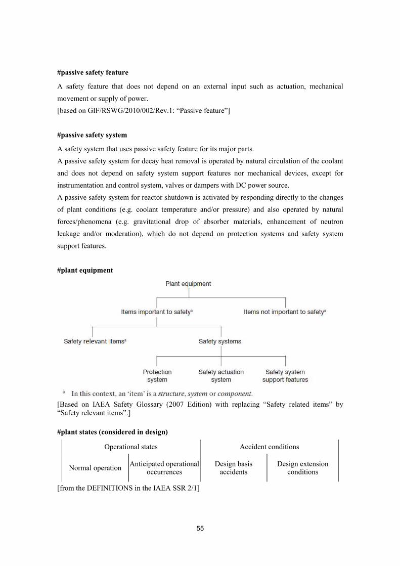
55
#passive safety feature
A safety feature that does not depend on an external input such as actuation, mechanical movement or supply of power. [based on GIF/RSWG/2010/002/Rev.1: “Passive feature”]
#passive safety system
A safety system that uses passive safety feature for its major parts. A passive safety system for decay heat removal is operated by natural circulation of the coolant and does not depend on safety system support features nor mechanical devices, except for instrumentation and control system, valves or dampers with DC power source. A passive safety system for reactor shutdown is activated by responding directly to the changes of plant conditions (e.g. coolant temperature and/or pressure) and also operated by natural forces/phenomena (e.g. gravitational drop of absorber materials, enhancement of neutron leakage and/or moderation), which do not depend on protection systems and safety system support features.
#plant equipment
[Based on IAEA Safety Glossary (2007 Edition) with replacing “Safety related items” by “Safety relevant items”.] #plant states (considered in design)
Operational states Accident conditions
Normal operation Anticipated operational occurrences
Design basis accidents
Design extension conditions
[from the DEFINITIONS in the IAEA SSR 2/1]
56
#practically eliminated
The possibility of certain conditions occurring is considered to have been practically eliminated if it is physically impossible for the conditions to occur or if the conditions can be considered with a high level of confidence to be extremely unlikely to arise. [from FOOTNOTES in the IAEA SSR 2/1]
#primary coolant system
The coolant system used to remove heat from the reactor core and to transfer the heat to the coolant in the secondary coolant system.
#protection system
System that monitors the operation of a reactor and which, on sensing an abnormal condition, automatically initiates actions to prevent an unsafe or potentially unsafe condition. The system in this case encompasses all electrical and mechanical devices and circuitry, from sensors to actuation device input terminals. [from IAEA Safety Glossary (2007 Edition).]
#reactor coolant boundary
The reactor coolant boundary is defined as the barrier of components which contains the primary coolant. The breakage of this boundary induces a primary coolant leak. The reactor coolant boundary forms a barrier against radioactive materials release together with the reactor cover gas boundary.
#reactor coolant systems
All systems used to remove heat from the reactor core and transfer that heat to the ultimate heat sink. The reactor coolant systems includes: the primary coolant system, the secondary coolant system, the decay heat removal system, the cleanup facilities, and the power conversion system with associated coolant system.
#reactor cover gas boundary
The reactor cover gas boundary is defined as the barrier of components which contains the reactor cover gas. The breakage of this boundary induces a reactor cover gas leak. The reactor cover gas boundary forms a barrier against radioactive materials release together with the reactor coolant boundary.
57
#safe state
Plant state, following an anticipated operational occurrence or accident condition, in which the reactor is subcritical and the fundamental safety functions can be ensured and stably maintained for a long time. [from the DEFINITIONS in the IAEA SSR 2/1]
#safety actuation system
The collection of equipment required to accomplish the necessary safety actions when initiated by the protection system. [from IAEA Safety Glossary (2007 Edition).]
#safety feature for design extension conditions
Item designed to perform a safety function or which has a safety function in design extension conditions. [from the DEFINITIONS in the IAEA SSR 2/1]
#safety group
The assembly of equipment designated to perform all actions required for a particular postulated initiating event to ensure that the limits specified in the design basis for anticipated operational occurrences and design basis accidents are not exceeded. [from IAEA Safety Glossary (2007 Edition).]
#safety relevant item
An item important to safety that is not part of a safety system. [from “safety related item” in IAEA Safety Glossary (2007 Edition).]
#safety relevant system
A system important to safety that is not part of a safety system. A safety related instrumentation and control system, for example, is an instrumentation and control system that is important to safety but which is not part of a safety system. [from “safety related system” in IAEA Safety Glossary (2007 Edition).]
58
#safety system
A system important to safety, provided to ensure the safe shutdown of the reactor or the residual heat removal from the core, or to limit the consequences of anticipated operational occurrences and design basis accidents. Safety systems consist of the protection system, the safety actuation systems and the safety system support features. Components of safety systems may be provided solely to perform safety functions, or may perform safety functions in some plant operational states and non-safety functions in other operational states. [from IAEA Safety Glossary (2007 Edition).]
#safety system settings
The levels at which safety systems are automatically actuated in the event of anticipated operational occurrences or design basis accidents, to prevent safety limits from being exceeded. [from the DEFINITIONS in the IAEA SSR 2/1]
#safety system support features
The collection of equipment that provides services such as cooling, lubrication and energy supply required by the protection system and the safety actuation systems. [from IAEA Safety Glossary (2007 Edition).]
#secondary coolant system (or intermediate coolant system)
The coolant system used to transfer heat from the coolant in the primary coolant system to the working fluid in the turbine system such as a water/steam system via a heat exchanger.
#single failure
A single failure is a failure that results in the loss of capability of a system or component to perform its intended safety function(s) and any consequential failure(s) that result from it. The single failure criterion is a criterion (or requirement) applied to a system such that it must be capable of performing its task in the presence of any single failure. [from FOOTNOTES in the IAEA SSR 2/1]
#sodium-concrete reaction
A chemical reaction due to the direct contact between sodium and concrete, which generates hydrogen gas that may cause overpressure in a containment.
59
#sodium fire
Fire caused by sodium combustion. Sodium spontaneously catches fire when exposed to air at the operating temperature of an SFR.
#sodium water reaction
A chemical reaction caused by the direct contact between sodium and water/steam.
#steam generator
A heat exchanger to transfer heat from a sodium system to a water/steam system.

60
APPENDIX
(A) Illustration of an Approach to Identify Practically Eliminated Situations by
using Objective Provision Trees (OPTs)
(B) Examples of Postulated Initiating Events for AOOs and DBAs
61
Appendix (A): Illustration of an Approach to Identify Practically Eliminated Situations by using Objective Provision Trees (OPTs) An approach to identify candidates for situations to be practically eliminated is the use of Objective Provision Trees (OPTs) [A-1]. This involves analysing failure modes of the containment, challenging phenomena and their causes. Examples of OPTs for the JSFR containment, which is a steel-plate reinforced concrete containment vessel (SCCV) containing the primary coolant system, guard vessels and guard pipes [A-2], are shown in Figures A-1 to A-5.
Implementing measures for each individual situation will be required. Situations, which cannot be managed by the design at acceptable conditions, are considered as candidates for practically eliminated situations. Design modification should be considered to cope with them. All initiators that could lead to situations that need to be practically eliminated need to be identified and proper design measures should be provided to prevent such situations to arise. Mitigation of consequences of core damage is included in DEC “mitigation of core damage”, hence the mitigation situations, for which such measures should be reasonably implemented, are not considered for practical elimination.
Challenging Phenomena Generating Mechanical Loads
Challenging phenomena and their causes in the “mechanical loads” domain are shown in Figures A-2 and A-5 for JSFR. These situations might cause containment failures due to direct heating of the containment atmosphere by dispersed molten fuel, large sodium spray fire, deflagration or detonation of hydrogen, and molten fuel-coolant interaction (vapour explosion). Energetic fuel dispersion should be prevented. Thus, design measures to prevent the causes of severe reactivity insertions, e.g., energetic core damage due to unprotected transients, should be provided. Although mitigation measures for the unprotected transients are provided as DEC “mitigation of core damage”, severe reactivity insertion due to extreme initiating events, such as large gas flow through the core, large-scale core compaction and collapse of the core support structures, needs to be practically eliminated. Inerting of the containment atmosphere is a possible design measure to prevent or mitigate pressure loads from a large sodium spray fire or hydrogen explosions. In order to avert hydrogen generation, design measures for prevention of a reactor vessel (RV) melt-through or failure, and prevention of sodium and concrete contact, are required.
62
Challenging Phenomena Generating Thermal Loads
Challenging phenomena and their causes in the “thermal loads” domain are shown in Figures A-3 and A-5 for JSFR. These situations might cause a containment failure due to heating of the containment by a sodium pool fire, sodium vapour and gaseous fission products, due to floor concrete erosion from sodium-concrete reaction, and due to debris-concrete interaction or containment wall heating by a connecting sodium pool. Significant loads, which are caused by a RV melt-through due to complete loss of heat removal and core uncovering, and which cannot be reasonably managed by original design, should be practically eliminated by design modifications. It should be possible to design the containment to withstand other loads, i.e. those generated by a sodium pool fire and gaseous fission products.
Containment Bypass
Challenging phenomena and their causes in the “bypass” domain are shown in Figure A-4 for JSFR. These situations might cause a containment boundary failure due to thermal loads or a primary/secondary boundary failure due to mechanical loads.
Summary
Based on the above, the following candidates for situations to be practically eliminated in JSFR are identified:
A) Abnormal reactivity insertion leading to prompt criticality (large gas flow through the core, large-scale core compaction and collapse of the core support structures).
B) Complete loss of heat removal C) Core uncovering
REFERENCE [A-1] An Integrated Safety Assessment Methodology (ISAM) for Generation IV Nuclear
Systems, June 2011 [A-2] H. Hara, et. al., “Conceptual Design Study of JSFR (4) – Reactor Building Layout –“,
FR09, 08-13P, 2009
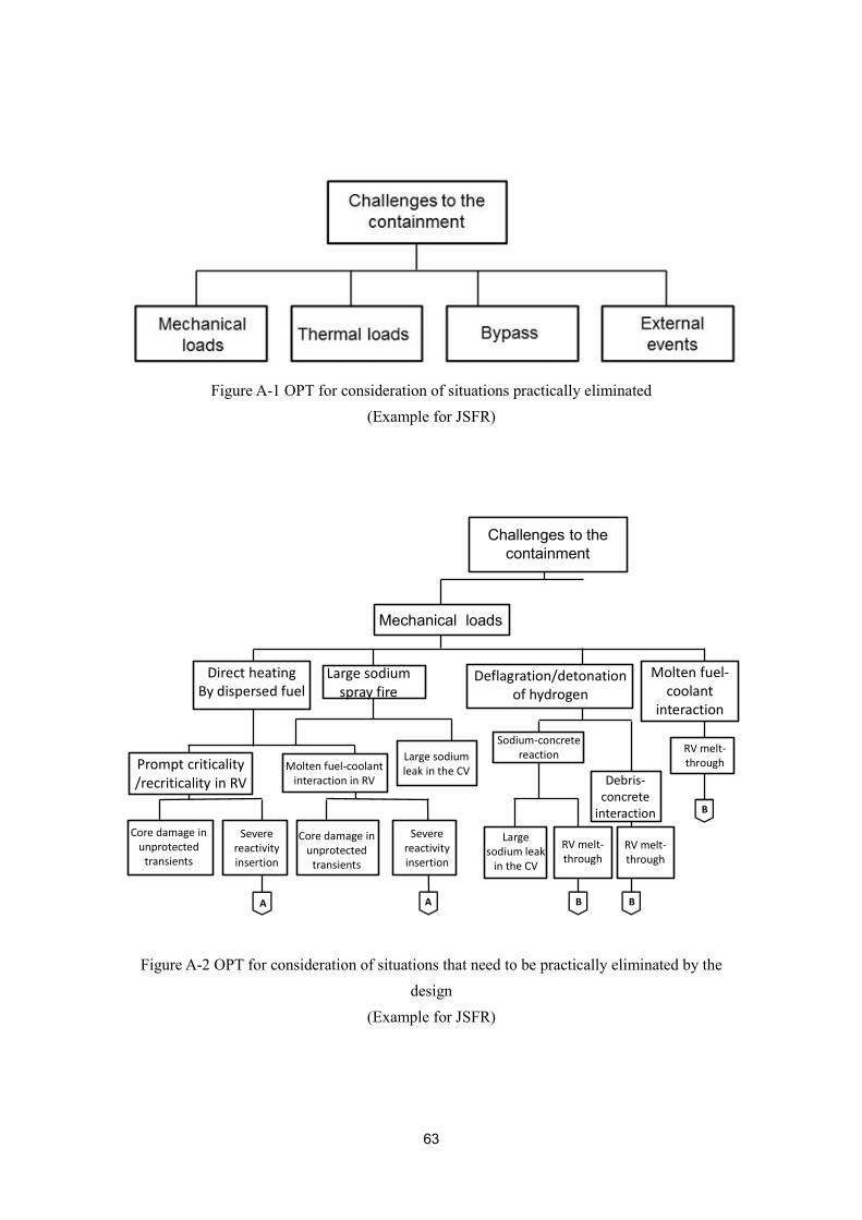
63
Figure A-1 OPT for consideration of situations practically eliminated
(Example for JSFR)
Figure A-2 OPT for consideration of situations that need to be practically eliminated by the
design (Example for JSFR)
A A B B
B
Mechanical loads
Large sodium spray fire
Deflagration/detonation of hydrogen
Molten fuel-coolant
interaction
Molten fuel-coolant interaction in RV
Sodium-concrete reaction
Debris-concrete
interaction
RV melt-throughPrompt criticality
/recriticality in RV
Severe reactivity insertion
Large sodium leak
in the CV
Large sodium leak in the CV
Challenges to the containment
RV melt-through
RV melt-through
Core damage in unprotected
transients
Severe reactivity insertion
Direct heatingBy dispersed fuel
Core damage in unprotected
transients
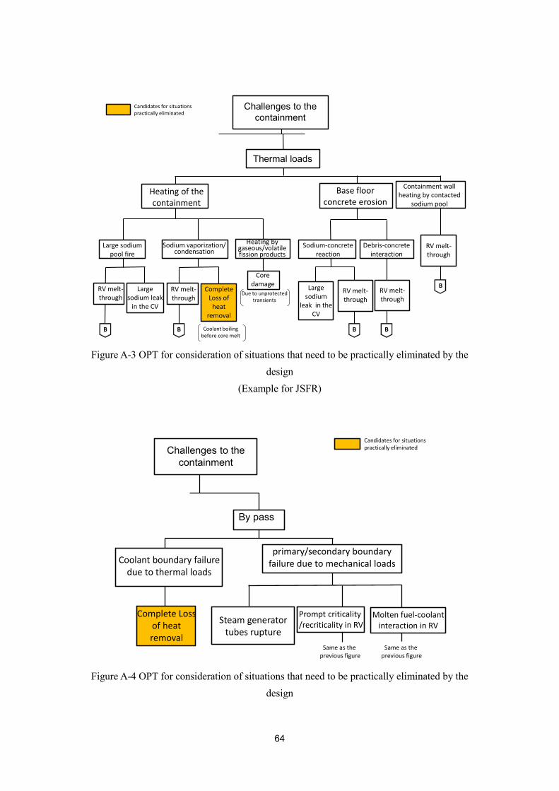
64
Figure A-3 OPT for consideration of situations that need to be practically eliminated by the
design (Example for JSFR)
Figure A-4 OPT for consideration of situations that need to be practically eliminated by the
design
B B BB
B
Coolant boiling before core melt
Due to unprotected transients
Thermal loads
Heating of the containment
Base floor concrete erosion
Containment wall heating by contacted
sodium pool
Large sodium pool fire
Sodium vaporization/condensation
Heating by gaseous/volatile fission products
Sodium-concrete reaction
Debris-concrete interaction
Core damage
Complete Loss of
heat removal
Large sodium leak
in the CV
Large sodium
leak in the CV
Challenges to the containment
RV melt-through
RV melt-through
RV melt-through
RV melt-through
RV melt-through
Candidates for situations practically eliminated
By pass
Coolant boundary failure due to thermal loads
primary/secondary boundary failure due to mechanical loads
Complete Loss of heat removal
Steam generator tubes rupture
Prompt criticality/recriticality in RV
Molten fuel-coolant interaction in RV
Same as the previous figure
Challenges to the containment
Same as the previous figure
Candidates for situations practically eliminated

65
(Example for JSFR)
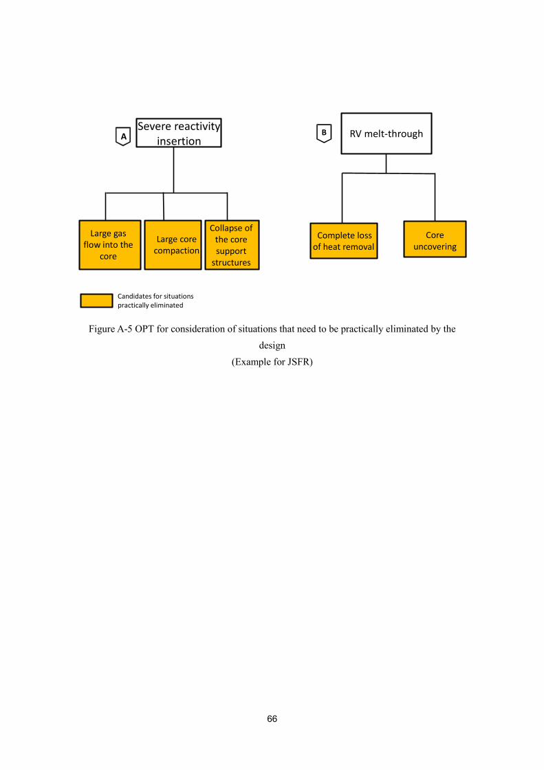
66
Figure A-5 OPT for consideration of situations that need to be practically eliminated by the design
(Example for JSFR)
A BSevere reactivity insertion
Large gas flow into the
core
Collapse of the core support
structures
Large core compaction
Core uncovering
RV melt-through
Candidates for situations practically eliminated
Complete loss of heat removal
67
Appendix (B): Examples of Postulated Initiating Events for AOOs and DBAs
Using the Objective Provision Tree (OPT) method, presented in the Integrated Safety Assessment Methodology (ISAM) [B-1] and proposed by the GIF Risk Safety Working Group (RSWG), the challenges and mechanismsB1 for preventing core degradation and securing the containment function are identified for a typical Sodium-cooled Fast Reactor (SFR) design. Consequently, typical postulated initiating events and design limits for AOOs and DBAs (limited to the reactor; fuel handling and waste treatment facilities are not considered) are identified as shown in Table B-1.
REFERENCE [B-1] An Integrated Safety Assessment Methodology (ISAM) for Generation IV Nuclear Systems, June 2011
B1 Challenges: generalized mechanisms, processes or circumstances (conditions) that may have an impact on the intended performance of safety functions. Challenges are caused by a set of mechanisms having consequences that are similar in nature. Mechanisms: specific reasons, processes or situations whose consequences might create challenges to the performance of safety functions.
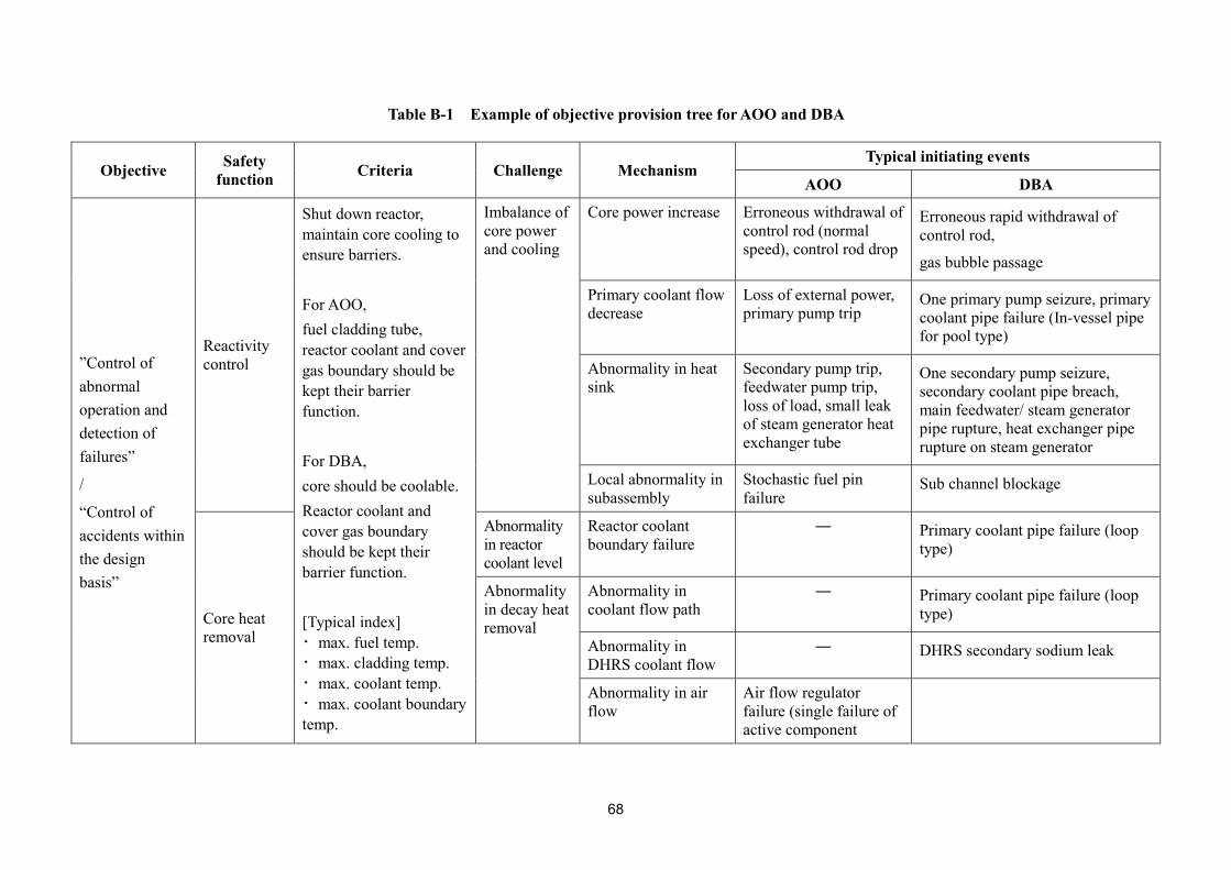
68
Table B-1 Example of objective provision tree for AOO and DBA
Objective Safety function Criteria Challenge Mechanism
Typical initiating events
AOO DBA
”Control of abnormal operation and detection of failures”
/
“Control of accidents within the design basis”
Reactivity control
Shut down reactor, maintain core cooling to ensure barriers. For AOO, fuel cladding tube, reactor coolant and cover gas boundary should be kept their barrier function. For DBA, core should be coolable. Reactor coolant and cover gas boundary should be kept their barrier function. [Typical index] ・max. fuel temp. ・max. cladding temp. ・max. coolant temp. ・max. coolant boundary temp.
Imbalance of core power and cooling
Core power increase Erroneous withdrawal of control rod (normal speed), control rod drop
Erroneous rapid withdrawal of control rod,
gas bubble passage
Primary coolant flow decrease
Loss of external power, primary pump trip
One primary pump seizure, primary coolant pipe failure (In-vessel pipe for pool type)
Abnormality in heat sink
Secondary pump trip, feedwater pump trip, loss of load, small leak of steam generator heat exchanger tube
One secondary pump seizure, secondary coolant pipe breach, main feedwater/ steam generator pipe rupture, heat exchanger pipe rupture on steam generator
Local abnormality in subassembly
Stochastic fuel pin failure
Sub channel blockage
Core heat removal
Abnormality in reactor coolant level
Reactor coolant boundary failure
― Primary coolant pipe failure (loop type)
Abnormality in decay heat removal
Abnormality in coolant flow path
― Primary coolant pipe failure (loop type)
Abnormality in DHRS coolant flow
― DHRS secondary sodium leak
Abnormality in air flow
Air flow regulator failure (single failure of active component
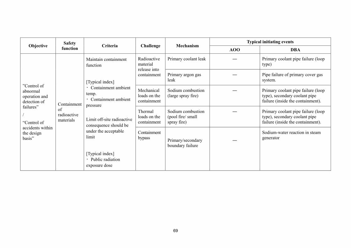
69
Objective Safety function Criteria Challenge Mechanism
Typical initiating events
AOO DBA
”Control of abnormal operation and detection of failures”
/
“Control of accidents within the design basis”
Containment of radioactive materials
Maintain containment function
[Typical index] ・Containment ambient temp. ・Containment ambient pressure
Limit off-site radioactive consequence should be under the acceptable limit
[Typical index] ・Public radiation exposure dose
Radioactive material release into containment
Primary coolant leak ― Primary coolant pipe failure (loop type)
Primary argon gas leak
― Pipe failure of primary cover gas system.
Mechanical loads on the containment
Sodium combustion (large spray fire)
― Primary coolant pipe failure (loop type), secondary coolant pipe failure (inside the containment).
Thermal loads on the containment
Sodium combustion (pool fire/ small spray fire)
― Primary coolant pipe failure (loop type), secondary coolant pipe failure (inside the containment).
Containment bypass
Primary/secondary boundary failure
―
Sodium-water reaction in steam generator