Safety and Certification Approaches for Ethernet-based Aviation
124
DOT/FAA/AR-05/52 Office of Aviation Research and Development Washington, D.C. 20591 Safety and Certification Approaches for Ethernet-Based Aviation Databuses December 2005 Final Report This document is available to the U.S. public through the National Technical Information Service (NTIS), Springfield, Virginia 22161. U.S. Department of Transportation Federal Aviation Administration
Transcript of Safety and Certification Approaches for Ethernet-based Aviation

DOT/FAA/AR-05/52 Office of Aviation Research and Development Washington, D.C. 20591
Safety and Certification Approaches for Ethernet-Based Aviation Databuses December 2005 Final Report This document is available to the U.S. public through the National Technical Information Service (NTIS), Springfield, Virginia 22161.
U.S. Department of Transportation Federal Aviation Administration

NOTICE This document is disseminated under the sponsorship of the U.S. Department of Transportation in the interest of information exchange. The United States Government assumes no liability for the contents or use thereof. The United States Government does not endorse products or manufacturers. Trade or manufacturer’s names appear herein solely because they are considered essential to the objective of this report. This document does not constitute FAA certification policy. Consult your local FAA aircraft certification office as to its use. This report is available at the Federal Aviation Administration William J. Hughes Technical Center’s Full-Text Technical Reports page: actlibrary.tc.faa.gov in Adobe Acrobat portable document format (PDF).

Technical Report Documentation Page 1. Report No. DOT/FAA/AR-05/52
2. Government Accession No. 3. Recipient’s Catalog No.
5. Report Date
December 2005
4. Title and Subtitle
SAFETY AND CERTIFICATION APPROACHES FOR ETHERNET-BASED AVIATION DATABUSES
6. Performing Organization Code
7. Author(s)
Yann-Hang Lee1, Elliott Rachlin2, and Philip A. Scandura, Jr.28. Performing Organization Report No.
10. Work Unit No. (TRAIS)
9. Performing Organization Name and Address 1Arizona State University
Office of Research and Sponsored Projects Box 873503 Tempe, AZ 85287-3503
2Honeywell Laboratories
2111 N. 19th Avenue Phoenix, AZ 85027
11. Contract or Grant No.
13. Type of Report and Period Covered
Final Report 12. Sponsoring Agency Name and Address
U.S. Department of Transportation Federal Aviation Administration Office of Aviation Research and Development Washington, DC 20591
14. Sponsoring Agency Code AIR-120
15. Supplementary Notes
The Federal Aviation Administration Airport and Aircraft Safety R&D Division COTR was Charles Kilgore. 16. Abstract
With the advent of higher-performance computing and communication systems, aircraft will have the capability to process an unprecedented amount of information pertaining to performance, safety, and efficiency. Flight instruments will be integrated to share information and to cooperate with each other. It is inevitable that a high-speed and versatile network infrastructure will be required in the next generation of aircraft. One commercial off-the-shelf technology, Ethernet, is seen as potentially attractive in avionics systems due to its high bandwidth, low wire count, and low cost. Ethernet has been used in the Boeing 777 to transmit non-flight-critical data and in the Boeing 767ER within a flight-critical display system. There are many safety concerns, however, when Ethernet is applied to flight-critical systems. The inherent nature of the Ethernet protocols can easily result in nondeterministic behavior and interference. These are significant technical hurdles that must be overcome before Ethernet will be a viable candidate as an aviation databus technology. In this report, safety and certification issues of Ethernet-based aviation databuses are summarized. Initially, it focuses on the issues of deterministic operations of Ethernet controller, device drivers, and communication stack, and possible solutions to avoid any adverse effects. In the latter part of the report, the discussion is centered on the evaluation criteria for the certifiability of Ethernet-based databuses. A prototype communication subsystem, to support deterministic data delivery in Ethernet, is also illustrated. Using this proposed design as an example, the report explains how the specific avionics requirements can be satisfied. Finally, it describes the implementation of the design on a test bed and analysis of the final results. 17. Key Words
Ethernet, Determinism, Software, Databus, Network, Criteria, Communication, Avionics
18. Distribution Statement
This document is available to the public through the National Technical Information Service (NTIS) Springfield, Virginia 22161.
19. Security Classif. (of this report)
Unclassified
20. Security Classif. (of this page)
Unclassified
21. No. of Pages
124 22. Price
Form DOT F1700.7 (8-72) Reproduction of completed page authorized

TABLE OF CONTENTS
Page EXECUTIVE SUMMARY xiii 1. INTRODUCTION 1-1
1.1 A Brief Overview of Ethernet 1-1 1.2 Why Ethernet is Being Proposed for Use on Aircraft 1-2 1.3 Why This Research is Needed 1-2 1.4 An Overview of This Research Project 1-2 1.5 Report Organization 1-5 1.6 Focus for Readers 1-6
1.6.1 Readers Concerned With Ethernet Databus Qualification 1-6 1.6.2 Readers Concerned With Ethernet Databus Development 1-6
2. ETHERNET-BASED DATABUS SYSTEM MODEL 2-1
3. TRAFFIC ANALYSIS 3-1
3.1 Overview of the Traffic Analysis 3-1 3.2 Computation Environment 3-2 3.3 Summary of Analysis Results 3-2
4. DETERMINISM IN COMMUNICATION SYSTEM 4-1
4.1 Determinism 4-1 4.2 Analysis of Nondeterminism in the Host—Hardware Components 4-1
4.2.1 Interrupt Chaining Latency 4-2
4.2.2 Interrupt Latency From Lock and Demand Legacy DMA Modes 4-3
4.2.3 Interrupt Latency From Context Switching 4-3
4.2.4 Virtual Memory and Noncontiguous Buffers 4-3
4.2.5 Latency From Non-Pre-Emptive DMA Mechanism 4-4
4.2.6 Disparity Between the Half-Duplex PCI Bus and Full-Duplex Ethernet Controller 4-4
4.2.7 The PCI Bus Arbitration Latency 4-4
4.2.8 Latency of PCI Burst Read/Write Process 4-4
iii
4.3 Analysis of Nondeterminism in the Host—Software Components 4-5
4.3.1 The CSMA/CD Protocol 4-5 4.3.2 Internet Protocol/Address Resolution Protocol 4-6 4.3.3 User Datagram Protocol/Transmission Control Protocol 4-6
4.4 Possible Control/Mitigation Techniques 4-7
4.4.1 Ethernet MAC Controller 4-7 4.4.2 Traffic Smoother 4-9 4.4.3 Recommendations on Network Stacks and Ethernet Drivers 4-10
5. ANALYSIS OF DETERMINISTIC DATA COMMUNICATION 5-1
5.1 Deterministic Message Transmission in Ethernet Bus 5-1
5.1.1 Delay Arbitration Protocol 5-1 5.1.2 Real-Time Ethernet 5-1
5.2 Deterministic Message Transmission in Switched Network 5-2
5.2.1 Switch Architectures 5-2
5.2.2 Analysis Tool—Network Calculus 5-2
5.2.3 Performance-Guaranteed Service Disciplines 5-3
5.2.4 Multicast Switches 5-6
5.2.5 Integrating Unicast and Multicast Traffic Scheduling With Parallel Switching Architecture 5-8
6. DATABUS EVALUATION AND QUALIFICATION 6-1
6.1 Background 6-1 6.2 Certification Authorities Position Paper 6-1 6.3 Certification Considerations 6-2 6.4 Use of COTS Products 6-2 6.5 Generic Evaluation Criteria 6-3 6.6 Ethernet Databus-Specific Evaluation Criteria 6-3
6.6.1 Ethernet-Based Aviation Databus 6-3 6.6.2 Evaluation Criteria 6-3
6.7 Satisfying the Avionics Application Requirements 6-7
6.7.1 Avionics Application Requirements 6-7
iv

6.7.2 Real-Time Communication Framework Requirements 6-9 7. A PROTOTYPE COMMUNICATION SUBSYSTEM ARCHITECTURE 7-1
7.1 Approach 7-1 7.2 Components of the Communication Subsystem 7-2
7.2.1 Workload Generator 7-2 7.2.2 Buffer Manager 7-3 7.2.3 Sender Component 7-3 7.2.4 Network Component 7-3 7.2.5 Receiver Component 7-4
7.3 Quality of Service Specifications 7-4 7.4 Traffic Regulator 7-5 7.5 Packet Scheduler 7-7 7.6 Network Component 7-8 7.7 Data Flow in Communication Subsystem 7-9 7.8 End-to-End Message Delay 7-9 7.9 Testing of the Prototype Communication Subsystem 7-13
7.9.1 Testing Environment 7-13 7.9.2 Test Cases 7-15
7.10 Results 7-17
7.10.1 Source Latency Analysis 7-18 7.10.2 Guaranteed Service Validation 7-19 7.10.3 End-to-End Delay Analysis 7-24
8. SUMMARY AND FUTURE WORK 8-1
8.1 Summary 8-1 8.2 Future Work 8-3
9. REFERENCES 9-1
10. RELATED DOCUMENTATION 10-1
11. GLOSSARY 11-1
APPENDICES
A—Results of the Traffic Analysis B—Detailed Design of the Communication Subsystem C—Introduction to Output-Queued and Input-Queued Switch Architectures D—Test Plan
v
LIST OF FIGURES
Figure Page 2-1 Communication Architecture in Ethernet-Based Aviation Databus System 2-1
2-2 End-Host System Architecture 2-2
4-1 Role of the Traffic Smoother in the Communication Architecture 4-10
5-1 Virtual Output-Queued Switching Architecture 5-9
5-2 A Parallel Switch Structure—POQ 5-10
7-1 Interconnection Diagram—Communication Subsystem 7-2
7-2 User-Level Socket Library 7-3
7-3 The Token Bucket Model 7-6
7-4 Connection Descriptor and Token Bucket Shaper Structures 7-6
7-5 Data Flow Diagram—Communication Subsystem 7-10
7-6 End-to-End Delay Model 7-11
7-7 Test Bed for the Subsystem Evaluation 7-13
7-8 Average Source Latency—Various Scale Factors 7-18
7-9 Average Scheduler Delay—Various Scale Factors 7-19
7-10 Guaranteed Service Validation—Normal Flows 7-20
7-11 Guaranteed Service Validation—Variation 1 (10% Scale Factor) 7-20
7-12 Guaranteed Service Validation—Variation 2 (10% Scale Factor) 7-21
7-13 Guaranteed Service Validation—Variation 3 (10% Scale Factor) 7-21
7-14 Guaranteed Service Validation—Variation 1 (50% Scale Factor) 7-22
7-15 Guaranteed Service Validation—Variation 2 (50% Scale Factor) 7-22
7-16 Guaranteed Service Validation—Variation 3 (50% Scale Factor) 7-23
7-17 Guaranteed Service Validation—Variation 1 (Two Flow Violations in Connections 1 and 2) 7-23
vi

7-18 Guaranteed Service Validation—Variation 2 (Two Flow Violations in Connections 2 and 3) 7-24
7-19 Guaranteed Service Validation—Variation 3 (Two Flow Violations in Connections 1 and 3) 7-24
7-20 Average End-to-End Delay—Various Scale Factors 7-25
vii

LIST OF TABLES
Table Page 5-1 Network Node Performance Estimation Theorems 5-3 5-2 Comparison of Several Work-Conserving Disciplines 5-4 5-3 Scheduling Order in a Frame 5-5 6-1 Generic vs Application-Specific Databus Evaluation Criteria 6-3 7-1 Flow Specifications 7-18
viii

LIST OF ACRONYMS AND SYMBOLS
dij Delay experienced by session i passing server j for D-EDD policy
h(α, β) The supremum of all values of δ(s), where δ(s) is defined as δ(s) = inf {τ ≥ 0 α(s) ≤ β(s + τ)}
ADS-B Automatic Dependent Surveillance-Broadcast
API Application Programming Interface
ARP Address Resolution Protocol
CAC Call admission controller
CAST Certification Authorities Software Team
CIOQ Combined Input Output Queuing
CM Configuration management
COTS Commercial off-the-shelf
CPU Central Processing Unit
CSMA/CD Carrier Sense Multiple Access with Collision Detection
D-EDD Delay Earliest Due Data
DEOS Digital engine operating system
DMA Direct memory access
EC Evaluation criteria
EDF-RR Earliest deadline first-round robin
EFIS Electronic flight instrument system
FAA Federal Aviation Administration.
FANS Future Air Navigation System
FCFS First-come, first-served
FIFO First-in, first-out
FMCS Flight Management Computer System
ix

GPS Generalized Processor Sharing
H-EDF-RR Hierarchical - Earliest Deadline First - Round Robin
HOL Head of Line
IEEE Institute of Electrical and Electronic Engineers
I/O Input/output
IP Internet protocol
IPC Interprocess communication
IQ Input queue
ISA Industry standard architecture
ISR Interrupt service routine
LAN Local Area Network
ms Millisecond
MAC Media Access Control
Mbps Mega bits per second
MII Medium Independent Interface
MTU Maximum transmission unit
NIC Network interface card
NP-EDF Non-pre-emptive earliest deadline first
OSI Open system interconnection
OQ Output queue
PCI Peripheral Component Interconnect
PHY Physical Layer
POQ Parellel output queued
QoS Quality of Service
x
RCS Rate-controlled services
RETHER Real-time ETHERnet
RFC Request For Comment
RR Round Robin
RTCA RTCA (formerly Radio Technical Commission for Aeronautics)
RTOS Real-Time Operating System
SCFQ Self-Clocked Fair Queuing
TCP Transmission Control Protocol
UDP User Datagram Protocol
VC Virtual Clock
VOQ Virtual output queued
VLSI Very large-scale integration
WFQ Weighted fair queuing
WF2Q Worst-case fair-weighted fair queuing
WS Wide-Sense
xi/xii

EXECUTIVE SUMMARY
Given that safety-critical real-time systems require deterministic behaviors in their communication operations, specialized communication networks have been used in the areas of avionics, defense, and space applications. This type of communication network is usually expensive, has a nominal bandwidth and complex wiring configurations, and has limited engineering support. On the other hand, with the advent of higher-performance computing and communication systems, aircraft will have the capability to process an unprecedented amount of information pertaining to performance, safety, and efficiency. Flight instruments will be integrated to share information and to cooperate with each other. It is inevitable that a high-speed and versatile network infrastructure will be required in the next generation of aircraft.
One commercial off-the-shelf technology, Ethernet, is seen as potentially attractive in avionics systems due to its high bandwidth, low wire counts, and low cost. It has been used in the Boeing 777 to transmit non-flight-critical data and in the Boeing 767ER within a flight-critical display system. However, there are many safety concerns when Ethernet is applied to flight-critical systems. The inherent nature of the Ethernet protocols can easily result in nondeterministic behavior and interference. These are significant technical hurdles that must be overcome before Ethernet will be a viable candidate as an aviation databus technology.
Ethernet was not designed to carry time-critical data. It is inherently nondeterministic in nature, and this is a factor that undermines its use in a time-critical system such as an avionics network. The nondeterminism in Ethernet is due to its use of the carrier sense multiple access with collision detection protocol for resolving bus contentions. Even in the presence of a collision-free environment for data transfer, one cannot guarantee that a data packet will be delivered on time. This is due to the fact that traffic in a real-time system tends to be bursty at times, and this burstiness can lead to buffer overflows both at the source (the transmit and receive buffers maintained by the Ethernet controller) and at the intermediate nodes, leading to packet loss. Therefore, the standard Ethernet will have to be supplemented with additional solutions to overcome this nondeterminism.
In this report, safety and certification issues of Ethernet-based aviation databuses are summarized. Initially, the report focuses on the issues of deterministic operations of Ethernet controller, device drivers, and communication stack, and possible solutions to avoid any adverse effects. A brief analysis of the traffic generated by a typical avionics system comprised of several avionics modules and applications is presented. This traffic analysis result can be used to estimate the amount of traffic generated by avionics applications and their properties. Then determinism in the communication system is discussed, and focus is placed upon the various hardware and software factors that cause nondeterminism in the end-node, including topics such as the use of Peripheral Components Interconnect-Direct Memory Access Ethernet controllers and the communication protocol stack. The report discusses issues concerned with the evaluation criteria for the qualification of Ethernet-based databuses. Several criteria are studied in detail to consider certifiability of future avionics databuses. With the intent to be more specific for the Ethernet-based aviation databuses, focus is placed upon four criteria: safety, data integrity, performance, and configuration management. Finally, a communication subsystem to support deterministic data delivery in Ethernet is illustrated. Using this prototype design as an example, the specific avionics requirements that can be satisfied are described, and a list of test
xiii

cases is provided. The example implementation is validated through the measurements of delay parameters, such as the source and receiver latency and the end-to-end delay for a mix of conforming and nonconforming traffic flows. The results of the performance evaluation show that real-time, deterministic support can be provided on an Ethernet-based databus without any changes to the underlying protocols or the hardware.
xiv

1. INTRODUCTION.
In the 21st century, advancements in data processing are resulting in higher bandwidth requirements. The speeds required are exceeding 10 megabits per second (Mbps) and the standard that is now being considered is one for 100 Mbps. Aviation is also moving from the use of low-bandwidth data to high-bandwidth data. Next-generation warning systems, for example, may want to combine map and air traffic data, terrain information, weather radar returns, information on man-made obstacles, and imagery on the airport environment, and finally fuse this information into single three-dimensional representation. The need for speedier communication to handle future growth requirements of avionic applications, such as the automatic dependent surveillance-broadcast (ADS-B) and Future Air Navigation System (FANS) warrant a move towards the use of a high-bandwidth databus as the communication medium in aircraft. Ethernet provides such a bandwidth and is being considered by aircraft and avionics manufacturers for current and future technologies. This report will consider its benefits and its safety and certification concerns. Potential solutions to these concerns will be presented and analyzed. As a two-phase research effort, the first phase focused on evaluating several approaches, while in the second phase, these approaches were implemented and results analyzed.
1.1 A BRIEF OVERVIEW OF ETHERNET.
Ethernet was developed at Xerox in 1973 as a part of a research program on personal workstations and distributed systems [1]. Ethernet is a simple or branching bus-like network that uses low-loss coaxial cable linked by repeaters. It has a carrier sense, multiple access with collision detection (CSMA/CD) network classification. The most common way of carrying out the CSMA/CD communications is by broadcasting packets of data on a cable that is accessible to all the stations on the network. All stations are continually listening to the cable for packets that are addressed to them. To avoid packet collision, Ethernet implements three mechanisms: (1) carrier sensing, (2) collision detection, and (3) back off [1]. In carrier sensing, the interface hardware at each station listens for the existence of a signal in the cable. For collision detection, the sending station also listens on its input port to make sure that the message sent and received is the same. Back off occurs when a collision is detected and a jamming signal is sent. Back off is the process of waiting for a period of time before retransmitting the message [1].
The standard for Ethernet is Institute of Electrical and Electronic Engineers (IEEE) 802.3. There have been three major standardization efforts with the IEEE 802.3 standard. The 1990 version operated at a maximum of 10 Mbps and is commonly known as 10BaseT. The 1995 version operated at a maximum of 100 Mbps and is commonly referred to as 100BaseT [2]. In 1998, the Gigabit Ethernet was standardized. It operates at a maximum of 1 gigabit per second. The gigabit Ethernet is compatible with the slower Ethernets [3].
As mentioned earlier, Ethernet uses a broadcast delivery mechanism in which each data packet transmitted on the physical medium is received by all stations. It is also possible, however, to transmit data packets to a single station or to a subset of the stations on the network. When a data packet is sent to a single station on the network, the packet is said to be unicast. When the data packet is sent to a subset (or a group) of the stations on the network, it is said to be multicast. Broadcasting is basically a subset of multicasting.
1-1

1.2 WHY ETHERNET IS BEING PROPOSED FOR USE ON AIRCRAFT.
Ethernet is attractive in the avionics world. It promises to accommodate future systems’ bandwidth demands, increase flexibility in avionics design and procurement, and reduce aircraft wire counts, thus lowering aircraft weight and operating costs. The use of Ethernet technology translates into greater flexibility in avionics architecture design and lower aircraft construction and operational costs. The most significant advantage of Ethernet (especially the 100-Mbps Ethernet) is its ability to allow for aircraft systems’ bandwidth growth. Another attraction of Ethernet is its promise to free avionics data transfer in integrated avionics systems from the logistical limitations of a backplane bus of the special-purpose communications bus, linking computing modules inside of a physical enclosure. So in the future, Ethernet will likely replace the backplane bus for at least some aircraft.
1.3 WHY THIS RESEARCH IS NEEDED.
Avionics Ethernets need to guarantee and control bandwidth allocation to users on the network and ensure that the right data arrives at the right destination at the right time. There will be some extra electrical requirements on the cable, which also need to be considered to support the higher frequencies [4]. There are many safety concerns, however, when Ethernet is applied to flight-critical systems. The inherent nature of the Ethernet protocols can easily result in nondeterministic behavior. This and the electrical requirements together form significant technical hurdles that must be overcome before Ethernet will be a viable candidate as an aviation databus. This report focuses on the safety concerns of Ethernet-based aviation databuses.
1.4 AN OVERVIEW OF THIS RESEARCH PROJECT.
The purpose of this research project was to provide a comprehensive investigation of the safety and certification issues of Ethernet-based aviation databuses. The goal is to address the nondeterminism of Ethernet and identify mechanisms to incorporate determinism into the network. To this end, design and test approaches of assuring reliable, accurate, and real-time communication services using commercial off-the-shelf (COTS) Ethernet hardware and software methods were examined. Through test experiments and model analyses of real-life avionics applications, an improved understanding of the potential safety issues was gained and enlightened guidance relative to network structures and operations is provided. Collaborative relationships with standards working groups, the aerospace industry, and regulatory agencies were established. Through this process, the relevant concerns are being discussed and addressed, and an industrywide effort to define a safe Ethernet-based aviation databus network has been initiated by industry.
The principal results of this research were twofold: (1) a solution to overcome the nondeterminism in Ethernet was found to be the use of a switched Ethernet topology, along with traffic regulation, bandwidth restriction (guarantee and control of bandwidth allocation), and call admission control and (2) Ethernet databus evaluation criteria were found within the categories of safety, data integrity, performance, and continued airworthiness. The report can be used by the certification specialist for Ethernet databus qualification during the certification process. Also, the report can be provided to the designer as a reference for system design and development.
1-2

This project was divided into two phases. Phase one addressed the theoretical background and a review of several technical concerns and approaches carried out. Phase 2 addressed actual implementation and testing of the proposed solution of phase 1. It also addressed the safety, certification, and databus evaluation issues.
It should be noted that the Federal Aviation Administration (FAA) is sponsoring this research effort; however, the results of the research do not constitute FAA policy or guidance. This research is intended to explore the safety and certification concerns and consider potential solutions. However, actual implementation of these potential solutions on real aviation projects should be coordinated with the certification authorities, as with any certification project.
As with any hardware and software components, the safety process of using Ethernet as an aviation databus began with an aircraft-level assessment of functions and hazards (using the SAE/ARP-4761 approach [5]). The guidelines for development, including RTCA/DO-254 for complex hardware and RTCA/DO-178B [6] for software were followed. In addition, several fundamental issues, including scheduling, safety and fault-tolerance, were examined carefully since Ethernet networks are designed for commercial non-safety-critical applications. To study the safety features, the characteristics of Ethernet protocols were investigated in bus and switched configuration, COTS Ethernet Media Access Control (MAC) silicon, network interface cards (NIC), and switches (specially regarding deterministic transmission-reception operations, temporal and spatial protection, and real-time guarantees).
Also, the issues related to the test strategy of Ethernet-based aviation databuses were investigated. A workload generator, which synthesizes traffic load profiles from avionics applications, was developed as part of this test strategy. Instead of using real airborne instruments, the communication specification of several real-life avionics applications, including autopilot, electronic flight instrument system (EFIS), flight management computer system (FMCS), and communication radio, were analyzed to establish a profile of message characteristics. This approach allows scaling the communication requirements and adjusting the traffic loads based on anticipated applications. The synthesized workload can then be supplied to Ethernet-based aviation databuses under various workload parameters. The other tools, which provide fault injection and performance measurement, are also useful for the certification and development phases.
As stated previously, through this project, it is endeavored to provide a solution to overcome nondeterminism in Ethernet. More precisely, efforts have concentrated on the following:
• Analysis of systemwide and nodewise traffic generation to understand the load on the system (as a whole) and the traffic generation patterns on a per node basis.
• Study of the factors contributing to nondeterminism in the nodes as well as in the Ethernet medium used by the nodes for communication.
• Study of schemes (both hardware and software) through which determinism could be incorporated both in individual nodes (end points of the network) and the intermediary elements (switches) of the network.
1-3
When determinism is discussed in this report, it is meant in terms of the bounds that can be achieved for such parameters that affect real-time traffic, such as delay and jitter. To obtain performance bounds, a static approach is considered with which network traffic is smoothed and regulated. Thus, the worst-case behavior and resource requirements can be predicted.
Phase 1 of this research was a concept study phase in which the possibilities of applying various policies (e.g., scheduling of real-time communication packets) in the Ethernet as it exists today were studied. Several approaches (both hardware and software) to introduce determinism in Ethernet were identified and analyzed. Below is a summary of the tasks carried out towards the development of a deterministic Ethernet framework (the rationale for each will be discussed in this report).
• The communication subsystem (a software process) residing on each node in the network was developed. All traffic sent by the concerned avionic application and intended for another similar application passes through this communication subsystem. This subsystem bounds the delay experienced by a data packet at the end-nodes. Thus, it addresses the issue of incorporating determinism at the individual nodes of the network.
• A new packet-scheduling algorithm, Earliest Deadline First-Round Robin (EDF-RR), was developed for distributed real-time applications such as flight-critical applications. According to the analysis of the delay bounds and buffer requirements obtained in the appropriate switch architecture, EDF-RR is suitable for real-time communication.
• A new switching architecture called the Parallel Switching Architecture along with an extension of the EDF-RR algorithm (Hierarchical-EDF-RR) was developed. It is a solution to integrate unicast and multicast traffic scheduling in packet-switching networks with guaranteed performance.
• Investigated the factors affecting nondeterminism in the host (node) (e.g., in the network stack, Ethernet controller design, etc.) to minimize the overheads to real-time communication caused by those factors.
The impetus in phase 2 was on implementing these approaches, testing the design with appropriate data with a view to analyze the results, and defining the evaluation criteria for the qualification of Ethernet-based aviation databuses. The following is a list of tasks carried out in phase 2:
• Generic evaluation criteria were developed to certify future avionics databuses. Eight generic evaluation criteria are described that are independent of the design and implementation of any databus.
• Ethernet databus-specific evaluation criteria were developed to certify future Ethernet-based aviation databuses. These are the subset of the above generic evaluation criteria.
• A detailed timing analysis of the communication subsystem was performed to obtain precisely the execution budgets of the individual threads of the subsystem. Their effect on the timely delivery of data in the network was determined and the approaches for adequate resource reservation throughout the system was devised.
1-4

• A thorough analysis of some of the mechanisms used in the communication subsystem is worked out in much greater detail. An example mechanism includes one to handle incoming connection requests (Call Admission Control) and handling exceptions in the system behavior.
• A test bed was developed and used to disclose the characteristics of Ethernet-based databuses. The suite includes tools for real-time traffic generation and performance measurement. Sample test benchmarks were constructed based on practical applications.
A close collaboration with the FAA research team was extremely helpful in identifying the acceptance criteria and in defining the functions of the test suite.
1.5 REPORT ORGANIZATION.
This report is organized as follows:
• Section 2 gives a brief overview of the system architecture based on Ethernet databus.
• Section 3 provides the brief analysis of the traffic generated by a typical avionics system comprised of several avionics modules and applications. This study was done to estimate the amount of traffic generated by avionics applications and to understand the traffic patterns (such as data rates, packet length distributions, and burstiness). The effect of unicasting and multicasting in such environment was also identified.
• Section 4 describes the determinism in the communication system and focuses on the various hardware and software factors that cause nondeterminism in the end-node, including topics such as the use of Peripheral Components Interconnect-Direct Memory Access (PCI-DMA)-based Ethernet controllers and the communication protocol stack.
• Section 5 discusses the deterministic data communication and quality of service (QoS)-related problems in packet-switching networks. A solution is proposed in terms of switch architecture and service discipline to integrate unicast and multicast traffic scheduling with guaranteed performance.
• Section 6 describes the general acceptance criteria for the qualification of future avionics databuses. It lists eight criteria required to evaluate any generic aviation databus. Among these evaluation criteria, four are defined to be databus-specific. Hence, these criteria are described in detail for Ethernet-based aviation databuses. These evaluation criteria are used to describe how the avionics application requirements can be satisfied.
• Section 7 describes the entire structure and model of an Ethernet-based aviation databus. It explains the proposed communication subsystem model design, data flow within the system, and implementation details of each component of the subsystem. The test environment setup and test plan is also provided. Finally, the results of the implementation are described. These results are evaluated by validating the performance of each component of the communication subsystem.
1-5
• Section 8 concludes the report by summarizing major achievements of the project and lists future research activities.
• Section 9 provides a list of references used throughout the research project.
• Section 10 is a list of related documentation.
• Section 11 is a glossary of key terms used in this report.
• Appendix A provides detailed analysis of the traffic generated during normal operation of the aircraft. Appendix B describes the detailed design of prototype communication subsystem. Appendix C gives an overview of output-queued and input-queued switches. Appendix D tabulates the test plan, described in section 7, in detail.
1.6 FOCUS FOR READERS.
This report provides information for a variety of readers. Two of the targeted reader groups are described below, with a suggested approach for reading this report.
1.6.1 Readers Concerned With Ethernet Databus Qualification.
The readers, concerned about the qualification of an aviation databus, should understand the certification requirements of the aviation databus. The general acceptance criteria, and more specifically, acceptance criteria defined for the Ethernet-based aviation databus (described in section 6) will help such readers to evaluate the databus for avionics requirements. The avionics application requirements and real-time communication framework requirements listed in section 6 will help these readers to validate the databus solution to be qualified. Before that, browsing through sections 1 and 4 will also be helpful for these readers to understand the basic Ethernet-based databus system model and the issues related to deterministic operations in Ethernet databus.
1.6.2 Readers Concerned With Ethernet Databus Development.
The software architects, designers, and researchers, developing a solution for an Ethernet-based real-time communication framework, should read sections 2 and 4 to understand the real-time communication requirements and nondeterministic factors involved in the Ethernet-based communication framework. The analysis of deterministic data communication described in section 5 and the prototype design, implementation and results (defined in section 7) will help to explore the possible solutions. If the Ethernet-based, real-time communication framework to be developed is within the avionics application domain, then traffic analysis of avionics data provided in section 3 and appendix A will be insightful.
1-6

2. ETHERNET-BASED DATABUS SYSTEM MODEL.
This section gives an overview of the architecture of an Ethernet-based aviation databus model. Figure 2-1 shows the entire setup with the individual nodes connected to the Ethernet network and the intermediate switches linking different collision domains (bus).
Avionic Instrument
Access Switch
Aircraft Backbone Switching Network
Backbone Switch
aviation application
aviation application
aviation application
task & comm. scheduling
communication stack modules
communication interface drivers
Ethernet MAC
Access Switch
aviation application
aviation application
aviation application
task & comm. scheduling
communication stack modules
communication interface drivers
Ethernet MAC
Avionic Application
Avionic Application
Avionic Application
Task & Communication Scheduling
Communication Stack
Communication Interface Drivers
Ethernet MAC
Avionic Instrument
FIGURE 2-1. COMMUNICATION ARCHITECTURE IN ETHERNET-BASED AVIATION
DATABUS SYSTEM As mentioned in the previous section, Ethernet can be made more deterministic by making the individual components in such a system deterministic by themselves. The components referred to here are the end-hosts (the avionic instrument is shown in figure 2-1) and the switches. The end-host system architecture and related topics are presented in this section, section 4, and section 7, whereas section 5 is devoted to switch architectures and its related topics. An end-host (node) of the Ethernet-based aviation databus consists of four parts (or layers), as shown in figure 2-2: a physical Ethernet network, an Ethernet MAC silicon or NIC, communication software and real-time operating system (RTOS) scheduling components, and an integration approach to merge communication services with high-level applications. Each layer is briefly described below:
• Application Layer. This is the layer where avionics applications (such as autopilot, EFIS, and FMCS) execute. These applications are communication intensive and use the aviation databus to communicate with each other. The destination application can be located either on the same host or on a remote host also connected to the same network.
• RTOS Layer. This layer provides the resource management facilities, the protocol stack, the necessary network services (e.g., sockets) used by the upper layers for invoking data transmission, and the basic interprocess communication (IPC) mechanisms, such as
2-1

mailboxes and shared memory used by the applications. The applications are scheduled by RTOS to run on the processor. The candidate RTOSs for the purpose of this research include Wind River System’s VxWorks® and Honeywell’s DEOS©.1
• Ethernet MAC Layer. The Ethernet MAC layer is nothing but the low-level device driver of the NIC or the Ethernet Controller. It implements first-in, first-out (FIFO) buffers for storing and forwarding packets to the underlying bus. The MAC layer is independent of the interconnection mechanism used in the network in the sense that its main functionality is to handle data packet arrivals from the upper layers and hand them to the physical network and vice versa irrespective of the whether the underlying network is a switched network or just a bus topology.
• Physical Network Layer. The Physical network can be bus based or switch based. In a bus-based system, a single bus connects all the nodes in the network, and data transmission can be carried out in only one direction at a time by any one node. The data transfer mode is therefore half duplex. Arbitration mechanisms are needed to avoid data collisions resulting from more than one node trying to access the bus at the same instant. Protocols such as the CSMA/CD are used for this purpose. The delay involved in transmitting is high in this case, since it involves waiting for bus access.
FIGURE 2-2. END-HOST SYSTEM ARCHITECTURE
1 Digital Engine Operating System (DEOS) refers to Honeywell’s RTOS for avionics applications.
2-2

In a switch-based system, separate conductors are used for sending and receiving data. In a fully switched network, Ethernet nodes only communicate with the switch and never directly with each other. Thus, they can forego the collision detection process and transmit at will. Hence, data transmission between the switch and the nodes takes place in a collision-free environment. This is called a full-duplex system since data can be transmitted in both directions simultaneously. This introduces more determinism into the system.
2-3/2-4

3. TRAFFIC ANALYSIS.
Given the Ethernet-based databus system model, it is necessary to understand the characteristics of data traffic in typical aviation applications. This section will provide statistical data extracted from the aircraft data specifications provided by Honeywell Laboratories Inc. (Phoenix, AZ). The results of this analysis will be used to determine the overall system load in terms of the amount of traffic generated and also to characterize traffic based on their rates of generation. This analysis can also be used to determine how much data is typically handled by any communication system on a per node basis.
3.1 OVERVIEW OF THE TRAFFIC ANALYSIS.
This section summarizes the traffic analysis carried out for a sample set of data reflecting information flow on the aircraft bus. The objectives of this traffic analysis were as follows:
• To find the raw traffic data generated with the basic information available at present without applying any of the other parameters such as the round-trip time and intrapacket delay, as is usually the case in any traffic analysis report.
• To find the effect of the use of the three main protocols, i.e., MAC, Internet Protocol (IP), and Transport Control Protocol (TCP), for data transmission in terms of the traffic generated by each due to the overheads on the basic Ethernet data frame.
• To find the effect of the use of multicasting in data transmission whenever possible and to compare resultant traffic generated when using a point-to-point versus a multipoint approach.
The information used as input to the traffic analyzer was comprised of several data fields in a spreadsheet format. A listing of those data fields is given below, along with a brief description of what each field stands for wherever necessary:
• Source Bus. The number of the bus used for data communication by the source and destination modules.
• Source Unit-Module. The source of data on the bus.
• Source Application. The specific application within the source unit-module that generated this data.
• Parameter Group. A logical name given to the data to be sent by the source.
• Dword Size. The size of the data to be sent (i.e., the parameter group) in double-word units (32 bit).
• Rate (ms). The frequency with which the source sends out this data on the bus in milliseconds.
• Consuming Unit-Module. The destination of the data on the bus.
3-1
• Consuming Application. The specific application within the destination unit-module that is the recipient of this data.
3.2 COMPUTATION ENVIRONMENT.
The analysis was carried out for four different types of aircraft data designated as Aircraft P, Aircraft H, Physical Aircraft P, and Physical Aircraft H. Here, Physical Aircraft and Aircraft actually represent the same aircraft. However, the Physical Aircraft data shows the movement of data between the physical modules/nodes in the system, whereas the Aircraft data shows the movement of data between the producing and consuming software applications allocated to the modules/nodes. Because the modules/nodes on these aircraft run an operating system with time and space partitioning, a module can run multiple applications, even if they are unrelated and are developed for different levels of assurance. This collocation of applications makes for less traffic at the device-to-device level than would be found in systems where these various applications must run on distinct hardware.
The traffic on each bus (of these dual-bus systems) was computed separately and an average was taken from the two. The bandwidth details of the Ethernet medium used was not taken into consideration since this analysis was done only to get an idea of the total load in the system without regard to the bandwidth available for that traffic. For purposes of computing the packet rate (i.e., the number of packets arriving on the bus in packets/second), the packet size was assumed to be fixed and was assumed to be equal to the minimum Ethernet packet size mainly because of the small data size for a majority of inputs. The traffic in terms of Mbps can be considered to be more accurate compared to that in packets/second for all practical purposes.
3.3 SUMMARY OF ANALYSIS RESULTS.
The results of the analysis are given in appendix A of this report and can be summarized as follows:
• By using multipoint communication (i.e., multicasting), there is a considerable reduction (almost 1/8) in the amount of traffic generated compared to using point-to-point communication. Thus, it would be a worthwhile exercise to explore the possibilities of using multicasting in the aircraft databus setup. If constrained to use a 10-Mbps Ethernet, one can make use of multicasting to satisfy the high demand for bandwidth.
• There is not much overhead in terms of the traffic generated irrespective of the different protocols (i.e., IP, TCP, and MAC) used. However, this analysis does not take into account additional bytes that form part of the IP options when considering the traffic generated for IP and TCP.
• The per node data generated is well within the bandwidth available in 10-Mbps Ethernet, and most of the data sent is usually very small, even though it is sent frequently. This kind of categorization of data can help to provide different services for data, which is of a minimal fixed size, and data that needs fragmentation and is of variable size.
3-2

4. DETERMINISM IN COMMUNICATION SYSTEM.
This section defines determinism in a real-time communication system. It also identifies factors resulting in the nondeterministic behavior of the software and hardware components on the end-host system. The end-host architecture specified in section 2 holds for the purpose of this analysis. Additionally, potential steps to mitigate the nondeterminism are mentioned where such steps are possible.
4.1 DETERMINISM.
Before listing the factors that affect deterministic data transmission and reception, let us define clearly what is meant by determinism. Determinism, at a network level, can be defined as the ability of the network to guarantee delivery of messages (data) to the nodes belonging to that network within a specified period of time. At the individual node level, determinism is used as a measure of the concerned system’s ability to process an input in a time-predictable fashion. For this research project, determinism, as defined by the former, is considered, though determinism at both levels is equally important. Together they lead to a highly dependable system, especially in an environment such as in this project where the nodes represent the various avionics applications with the Ethernet acting as the medium of communication between them. In fact, in this scenario, the two forms of determinism are very strongly intertwined and each drives the other.
The factors that affect the deterministic transmission and reception of data on Ethernet are summarized below:
• The amount of bandwidth available on the network • The number of nodes connected to the network • The average rate of traffic flow through the network and its burstiness • The protocols used for data communication and conflict resolution on the network • The data transmission and reception rates of the individual nodes • The interconnection hardware used The remainder of section 4 addresses the issues related to determinism at the node level.
4.2 ANALYSIS OF NONDETERMINISM IN THE HOST—HARDWARE COMPONENTS.
Assuming a PCI bus-based hardware platform and a NIC, which is under the control of a host processor, the analysis of various delay factors is carried out. These delay factors are due to interrupt latency, the latency of PCI bus access and arbitration, memory read/write operations, and FIFO buffer.
PCI bus, a local bus standard developed by Intel, is widely used in modern computer systems and has become a dominant one. The main advantage that PCI has over other buses (e.g., Industry Standard Architecture (ISA)) is its enormous bus bandwidth. For instance, for a 32-bit PCI bus (PCI can also be implemented as 64 bits) that runs at a clock speed of 33 MHz, a throughput rate of up to 133 Mbps can be achieved. Also, PCI bus supports decoupling central processing unit (CPU) and peripheral buses as much as possible. DMA, a way to reduce the CPU involvement
4-1

in transferring large amounts of data between the main memory and input/output (I/O) devices, is often adopted in PCI bus systems. Therefore, it is not a surprise to see that these days Ethernet controllers have a PCI-DMA interface.
Even though it has a high throughput rate, the PCI bus was not initially developed to accommodate time-critical applications and does not guarantee high data transfer performance at all times. Industrial testing shows PCI bus performance is very complex and, consequently, hard to predict. Thus, in a real-time system where communication tasks are bound by PCI-DMA Ethernet, PCI bus is going to be the bottleneck of Ethernet NIC in terms of throughput and latency. PCI-DMA Ethernet controllers transmit and receive data frames by making use of interrupt mechanism, burst reading, and writing to PCI devices (DMA operations). These result in some nondeterministic features that are not suitable to real-time communications.
To ensure the deterministic communication performance of PCI-DMA Ethernet NIC, factors contributing to its nondeterminism should be carefully analyzed. These factors are explained in the sections below.
4.2.1 Interrupt Chaining Latency.
According to the PCI specification [7], “the system vendor (computer vendor) is free to combine the various interrupt signals from the PCI connector in anyway to connect them to the interrupt controller.” Hence, a device driver may have much freedom to configure the device’s interrupt routing to the host machine. This may inadvertently degrade the entire system performance, in light of delay and predictability, when multiple devices have interrupts associated with the same interrupt service routine (ISR) in the host machine. In other words, an interrupt chain is formed.
To illustrate the performance deterioration resulting from interrupt routing, consider a typical PCI/ISA combination design in which similar interrupt signal pins from various PCI connectors are connected (e.g., all the INTA#2 pins are connected and all INTB# pins are connected) and directed to a programmable interrupt router. The router then routes the interrupt group to an existing ISA interrupt, which leads an interrupt chain. The flaw with interrupt chaining is an increase in interrupt latency, if a specific interrupt service routine does not stay at the head of the chain. The interrupt latency (the time elapsed from the time a device activates an interrupt to the time the corresponding interrupt service routine runs) varies, depending on where the interrupt service routine for the device is located in the chain. In the worst-case, when all the interrupts in the chain are invoked simultaneously, the latency of the last interrupt would be much longer than when it is invoked by itself. It is possible that the interrupt chain can be updated at run time. In other words, some interrupts in the chain may be disabled, some may be added to the chain, and some already in the chain, but disabled, may be enabled again. All of these can happen at system run time.
All the factors mentioned above contribute to the nondeterministic interrupt latency of PCI devices such as PCI-DMA Ethernet NIC. Even if only one interrupt is invoked in an interrupt chain (e.g., the last one in the chain) for reaching its associated interrupt service routine, the CPU would have to traverse the whole interrupt chain on every interrupt, wasting processing cycles.
2 The notation INTA# represents a signal pin named INTA, which is active when low (i.e., negative logic).
4-2

This gives rise to an increase in interrupt latency. Because of long and unpredictable interrupt latencies, the use of PCI-DMA Ethernet NIC may cause nondeterminism in real-time systems.
4.2.2 Interrupt Latency From Lock and Demand Legacy DMA Modes.
Pre-emption is an important feature in real-time systems, which can improve system deterministic performance. When applying PCI-DMA Ethernet NIC in real-time applications, it is normally expected that DMA operations are capable of supporting pre-emption from other higher-priority transactions. However, DMA modes (such as those by PCI-DMA Ethernet controllers) do not permit pre-emption attempts by other bus masters. During DMA operation cycles, the CPU can go on executing some instructions in the pipeline or cache; but when I/O or main memory-addressing operations are encountered, the CPU will halt until the DMA cycle is accomplished. Since almost all interrupt service routines must perform at least one I/O operation to the bus (e.g., at a minimum, an end of interrupt command must be sent to the programmable interrupt controller), it is possible to prevent the ISR from completing any I/O until the legacy DMA transaction is done. As an example, with PCI-DMA Ethernet controller, suppose that the controller has received a frame and an interrupt is generated to inform the host machine of the coming frame, it is possible that the PCI bus is possessed by a DMA cycle of the transmit process, which cannot be pre-empted. Since the host can find out the frame’s arrival only after the interrupt is returned, the receive process is postponed by the DMA cycle.
4.2.3 Interrupt Latency From Context Switching.
In modern operating systems, any interrupt response involves context switching between kernel mode and user mode. Depending on process scheduling and the interrupt management mechanism, there are some nondeterministic factors in context switching in terms of latency. For instance, in the Linux system, the work that the ISR should do is assigned to what is called a bottom half, which is scheduled to run at a later time. The duration from the time an interrupt is triggered to the time when the bottom half is executed could be quite large, since some urgent work might have to be completed before the bottom half is run and is thus nondeterministic.
4.2.4 Virtual Memory and Noncontiguous Buffers.
DMA devices reference only a block of contiguous physical address. However, the operating system and application programs reference virtual memory. For a DMA device to run with the virtual memory manager of an operating system, the driver software for the device must assume the responsibility of supervising the data location and managing the data transfer between physical and virtual memory. Before data can be transferred, the virtual memory manager must be instructed to map the data buffer from virtual memory to physical memory (page in). Sufficient physical memory must be available to contain the entire buffer. In addition, physical memory must be locked so that it is not moved to another memory location (for example, performing a page out to meet the memory needs of another operation), while the DMA is in progress.
A DMA operation command is issued by the application program, which references the buffer in virtual memory. A DMA device (the operation executor) references contiguous physical address. But a contiguous buffer in virtual memory cannot guarantee contiguity in the physical
4-3

memory. It is possible that a contiguous buffer in virtual memory consists of multiple distinct (noncontiguous) physical segments. In that case, it will take more than one DMA transaction to transmit the data in this virtual memory buffer. The time to transmit two virtual buffers of data of the same length may vary greatly. The driver has to know exactly the mapping from virtual memory buffer to the segments of contiguous physical memory. The data in a fixed buffer in virtual memory could be transferred through DMA operations in a large range of time intervals at different times due to paging on demand and physical memory fragmentation in some operating systems.
4.2.5 Latency From Non-Pre-Emptive DMA Mechanism.
When one DMA transaction is executing, another DMA request of an even higher priority than the executing one cannot be granted until the current transaction terminates because the bus arbiter normally does not use the pre-emption mechanism to assign bus-to-master devices. DMA cycles on the PCI bus are proportional to the sizes of the data to be transferred. The larger the block of data to be transferred, the more delay that could be introduced to a latter DMA request when the former one is executing. The scenario, for example, to be considered in Ethernet NIC, is how to coordinate the DMA priorities of transmit and receive. Obviously, transmit and receive DMA operations influence transaction latency to each other since they share PCI address and databuses.
4.2.6 Disparity Between the Half-Duplex PCI Bus and Full-Duplex Ethernet Controller.
Most computer bus standards, including PCI, support only half-duplex mode. All bus operations are serialized such that read and write, for example, cannot be executed in parallel. On the other hand, it is expected that the Ethernet controller will run in full-duplex mode for real-time communications, using separate queues for transmit and receive. In spite of the full-duplex operation of the controller, the PCI bus by which the host transmits and receives frames can only be possessed by one master device at a time. This is the essential reason why the PCI bus is the bottleneck for applying this type of controller in real-time applications.
4.2.7 The PCI Bus Arbitration Latency.
Arbitration latency is defined as the number of bus clock cycles it takes between a master’s request of the bus and when the arbiter grants the bus to that master. This period is a function of the arbitration algorithm, the master’s priority and whether or not any other masters are requesting access to the bus. Thus, the arbitration latency is implementation dependent, and thus nondeterministic.
4.2.8 Latency of PCI Burst Read/Write Process.
For zero wait (PCI has no waiting status once a transaction is issued), PCI devices such as those in most PCI-DMA Ethernet controllers, the latency of burst read/write is unpredictable. A read/write operation is composed of an address phase and multiple data phases.
T = Ta + n*Td
4-4

where
T = time of a burst read/write Ta = time of an address phase n = size of data in one burst operation Td = time of a data phase
This time T can vary, depending on Td and n, thus resulting in nondeterminism.
The latencies and nondeterministic concerns mentioned in this section must be considered when designing the system and when choosing the Ethernet controller for use.
4.3 ANALYSIS OF NONDETERMINISM IN THE HOST—SOFTWARE COMPONENTS.
This section discusses only those protocols (network, Ethernet MAC, and transport layer) that are of concern in this project. Ethernet supports protocol multiplexing that allows an Ethernet to carry multiple distinct network layer protocols such as AppleTalk, Digital Equipment Corporation’s network protocol suite (DECnet), IP, and Internetwork Packet Exchange. Upon receiving an Ethernet frame, a node must decide what protocol should accommodate the payload of the Ethernet frame by checking the frame’s Ether Type field. In the case of IP, its Ether Type is 0x0800. The frame is then processed by upper layer protocols such as User Datagram Protocol/Transmission Control Protocol (UDP/TCP).
4.3.1 The CSMA/CD Protocol.
Ethernet uses a CSMA/CD mechanism to resolve contention in case of simultaneous data transmission. If two nodes transmit messages simultaneously, the messages collide and are destroyed (i.e., data is lost). The two transmitting nodes listen to the network to detect a message collision. If a collision is detected, the transmitting nodes wait a random length of time to retry transmission. The standard binary exponential back off algorithm determines this random length of time. The randomness of this waiting time essentially makes CSMA/CD nondeterministic.
Additionally, if 16 collisions are detected, the node stops transmitting and reports an error. To relate collisions to time delays, the blocking time of Ethernet is considered. The blocking time is defined as the time a message must wait to be sent, once a node is ready to send the message. It includes waiting time (while other nodes are sending messages) and the time needed to resend the message, if a collision occurs. If a message experiences n collisions (where n≤16), its blocking time can be
Tblock = ∑ Tk + Tresid, (for k = 1 to n)
Where Tresid denotes the residual time until the network is idle, and Tk is the random back off duration after the kth collision. It is easy to see that Tblock is not deterministic and may be unbounded due to the discarding of messages [8].
However, CSMA/CD is used only when the network topology is a bus-based configuration. In a full-duplex, fully switched topology, CSMA/CD is turned off; hence, it is a collision-free environment (i.e., There is a dedicated link, one for transmission and another for reception
4-5
between each node. Also, nodes are never directly connected to other nodes in the network, they are always connected through switches).
4.3.2 Internet Protocol/Address Resolution Protocol.
For IP to use Ethernet to communicate with an IP stack on another station, it must have a way to discover the destination MAC address. A table of neighbor IP addresses versus MAC addresses must be maintained for the sake of mapping from IP address to MAC address.
The IP suite has a protocol called Address Resolution Protocol (ARP) running directly over Ethernet without an IP head. ARP is used by IP end-stations to find neighbor MAC addresses with a certain IP address, and then the owner of that address will respond directly to the requester, if it gets the request. An ARP frame is a special Ethernet frame.
ARP works in the following manner. When a station is initialized, it establishes an ARP cache. If the station wants to send an IP packet to another station, it should obtain the destination MAC address. If the MAC address can be found by looking up the source station’s ARP cache, the station will use the MAC address for the communication. Otherwise, an ARP frame is sent to the broadcast address, so that all stations on that Local Area Network (LAN) will hear it. All these stations can update their ARP cache if they do not know the source station’s MAC address. If the destination station is on the LAN, it will reply with an ARP frame to inform the source about its MAC address. Once the source receives an ARP reply, it will store the association between the remote IP address and its MAC address in a table. This address translation table, also referred to as ARP cache, is supported both statically and dynamically in most IP over Ethernet implementations including the Berkeley networking code. Dynamic entries are added and removed automatically over time. Static entries remain in the cache until the computer is restarted. ARP cache needs periodic updating to maintain accurate information on IP-to-MAC bindings, especially when nodes in the network do not have static IP addresses.
It is obvious that ARP introduces a nondeterministic process of IP packet transmission. This is because of the variable time taken to resolve an IP address that has an entry in the ARP cache compared to one that does not. For supporting delay-guaranteed or real-time applications by IP over Ethernet, static ARP cache is more suitable than a dynamic ARP cache. Static ARP takes the advantage of avoiding ARP requests at the cost of losing flexible administration.
4.3.3 User Datagram Protocol/Transmission Control Protocol.
Both UDP and TCP are transport layer protocols that provide ports to distinguish multiple applications running on a single node from one another among other services. TCP provides reliable transmission of data in an IP environment since it is connection-oriented. Among the services that TCP provides, are stream data transfer, reliability, efficient flow control, full-duplex operation, and multiplexing. However, TCP’s use of an acknowledgement and retransmission scheme for ensuring reliability makes it inherently nondeterministic. Besides this, TCP uses such mechanisms as the sliding window mechanism and others like the slow-start and multiplicative decrease mechanisms for congestion control that make it very complex and results in a lot of overhead in the communication.
4-6

UDP is a connectionless transport layer protocol. Unlike TCP, UDP adds no reliability, flow-control, or error-recovery functions to IP. Because of UDP’s simplicity, UDP headers contain fewer bytes and consume less network overhead than TCP. UDP is useful in situations where the reliability mechanisms of TCP are not necessary, such as cases where a higher-layer protocol might provide error and flow control. UDP is also equally nondeterministic. But given that, UDP is much faster in data delivery when compared to TCP and since traffic regulation and resource reservation is to be used as part of the application layer (the communication subsystem), determinism can be achieved by using UDP without the overhead of TCP.
4.4 POSSIBLE CONTROL/MITIGATION TECHNIQUES.
This section explores possible ways to address the issues leading to nondeterminism listed in the previous section in terms of the choices made for some of the hardware and software components of the host system.
4.4.1 Ethernet MAC Controller.
This section describes features desirable in an Ethernet controller for a more deterministic system behavior. The following two COTS Ethernet controllers are examined:
• Intel 82559 Fast Ethernet Multifunction PCI/CardBus Controller • Adaptec, AIC-6915 Ethernet LAN Controller A brief overview of the main features of each of the above named controllers will be given followed by a listing of some factors that may affect the deterministic transmission and reception of data on the target system and how the above controllers perform in this regard.
4.4.1.1 Intel 82559.
The Intel 82559 is a 32-bit PCI/CardBus controller with enhanced scatter-gather bus mastering capabilities that enables the Intel 82559 controller to perform high-speed data transfers over the PCI bus and CardBus. Its bus master capabilities enable the component to process high-level commands and perform multiple operations, which lowers CPU utilization by off-loading communication tasks from the CPU. Two large transmit and receive FIFOs of 3 Kbytes each help prevent data underruns and overruns while waiting for bus accesses. This enables the Intel 82559 to transmit data with minimum interframe spacing.
Some of the other salient features of this controller are:
• Fully integrated 10BaseT/100BaseTX LAN solution. • Capability to operate in either full-duplex or half-duplex mode. • Autonegotiation capability for speed, duplex, and flow control modes. • MAC and physical layer (PHY) interfaces combined in a single component.
4-7

4.4.1.2 Adaptec AIC-6915.
The Adaptec AIC-6915 is a PCI-compliant 10/100 Ethernet LAN controller. It features a 32/64-bit PCI master and supports 32- or 64-bit addressing for host buffers and transfers data up to the maximum burst rate of 133/266 Mbytes/sec with a maximum burst size of up to 2 Kbytes. The AIC-6915 integrates all the functions necessary for an Ethernet PCI adapter to directly connect (via a medium-independent interface (MII)-based PHY and line transformer) to a category 5 unshielded twisted pair or shielded twisted pair.
Some of the other salient features of this controller chip are:
• Enhanced interrupt mechanism to increase performance and reduce CPU utilization.
• Unlimited (limited only by the FIFO size) receive/transmit frame queuing in the FIFO to handle long PCI bus latencies.
• Programmable hardware-controlled transmit FIFO thresholds to prevent underrun of transmit FIFO and enhance overall system performance.
Section 4.2 listed factors affecting determinism in the Ethernet hardware. Since this section is devoted to Ethernet controllers, the specific features of the controllers themselves that will affect the determinism of the end-node are listed below:
• The hardware bus architecture used in the system (PCI/ISA) • The interrupt utilization • The transmit and receive buffer sizes • The design of the DMA controller 4.4.1.3 Selecting the Ethernet Controller for This Project.
Both the Intel 82559 and the Adaptec AIC-6915 are PCI bus-based. As is widely known, PCI buses deliver a very high bandwidth (compared to the ISA bus). They make use of the bus-mastering capability of PCI for high-speed data transfers. PCI bus masters, equipped with DMA, are very efficient since they do not need any microprocessor involvement. The scatter-gather DMA is one of the best methods of implementing bus mastering. It allows the PCI-DMA controller to work in cooperation with the virtual memory manager, and thus introduces more flexibility in the system. DMA reduces latency in serving a PCI device by reducing the data transfer time. It causes much fewer interrupts to the CPU, thus improving the overall system throughput. FIFO buffering is needed to balance the data transfer rates of the microprocessor and the memory and peripheral devices. The larger the buffer, the greater are the chances of data being transmitted reliably (i.e., without packet drops due to buffer overruns). The capability to transfer data in full-duplex mode further increases the bandwidth and results in lower intrapacket delays. These were some of the factors that influenced the selection of the above-mentioned Ethernet controllers for the purpose of this project.
4-8

As far as the delay of the Ethernet controller itself is concerned, the process of packet reception and transmission is relatively predictable. Ethernet controllers support priority-based, multiple-transmit and multiple-receive queues. During a receive operation, the driver should inspect the priority of the coming frame and put it to the appropriate queue. During a transmit operation, the controller would take a frame in the higher-priority queue to send out. This characteristic benefits the real-time applications. But this makes the driver somewhat more complicated than the simple first-come, first-served (FCFS) case. It is also not easy to evaluate QoS parameters (such as jitter) in FCFS since the influence of frame priority should be considered. The controller FIFO (same as FCFS) delay of a frame is determined by the backlog (the number of frames and frame size) in the FIFO when the frame arrives at the FIFO. With an FIFO-queuing mode, it is not difficult to analyze FIFO performance. For the scenario of multiple-priority FIFO queues, however, the analysis would be rather tricky considering priority influence.
After this initial analysis, the Intel 82559 Ethernet controller was selected over the Adaptec controller for this research project.
4.4.2 Traffic Smoother.
In real-time applications, real-time control messages need to be generated and exchanged among the stations that are connected to the network. Most proprietary control networks scan and send I/O continuously even though the data changes infrequently or slowly. An alternative approach is to send the data only when the data has changed. An event-driven approach for real-time control messaging is acceptable, provided that the underlying network can guarantee the timely delivery of the updated data. Although the former approach is used in most proprietary control networks, the latter approach is drawing considerable interest since it reduces the rate of generating the real-time messages. Here, it is assumed that control stations employ this event-driven approach in generating real-time control messages.
It is difficult to build the real-time control network using the standard UDP, TCP/IP, and Ethernet because the Ethernet MAC protocol and the CSMA/CD protocol has unpredictable delay characteristics. When both real-time and non-real-time packets are transported on an ordinary Ethernet LAN, real-time packets from a node may experience a large delay due to (1) contention with non-real-time packets on the originating node and (2) collisions with real-time and non-real-time packets from the other nodes. To resolve this problem, adaptive traffic smoothing can be deployed. Specifically, the traffic smoother is installed between the UDP/IP or TCP/IP layer and the Ethernet MAC layer and works as an interface between them. The architecture of the communication stack with the traffic smoother is illustrated in figure 4-1. First, the traffic smoother gives the real-time packets priority over non-real-time packets to eliminate contention within each local node. Second, it smoothes the non-real-time stream to reduce the collision with real-time packets from other nodes. This packet smoothing can dramatically reduce the packet-collision ratio on the network. The traffic smoother, installed at each node, regulates the node’s outgoing non-real-time stream to maintain a certain traffic generation rate. To provide a reasonable non-real-time throughput, the traffic generation rate is allowed to adapt itself to the underlying network load condition. This traffic smoother requires only a minimal change in the operating system kernel without any modifications to the current standard of the Ethernet MAC protocol or the TCP/IP or the UDP/IP protocol stack.
4-9

Application
UDP/IP
Traffic Smoother
Ethernet
FIGURE 4-1. ROLE OF THE TRAFFIC SMOOTHER IN THE
COMMUNICATION ARCHITECTURE 4.4.3 Recommendations on Network Stacks and Ethernet Drivers.
The following are some recommendations for IP stack and Ethernet driver implementations that are desirable in the context of this project.
• The communication stack should minimize the copying of data when passing a packet up or down through the layers of the stack. This feature is called zero copy. This feature essentially reduces the overall time taken for processing the packet. The incoming frame is just copied once to a generic buffer, which can be accessed by all the layers of the network stack.
• The driver for the Ethernet controller chip should support multiple-message queues for both transmission and receptions. Multiple-message queues prevent the bottleneck in the system.
• The communication stack should support priority, while processing received messages up through the layers of the stack to the application and vice versa. This helps to implement a priority-driven messaging system.
• The communication stack should provide options that allow it to operate in a mode that is optimized for Ethernet/IP. When operating in this mode, the stack will minimize CPU cycles required to determine if a message is Ethernet/IP. For example, the stack may filter by protocol ID or UDP/TCP port number before performing checksums.
• The IP stack must run as a scheduled task, rather than being implemented as a fast path (a thread that can be executed in as little time as possible) in the interrupt handler. This has significant implications for the queuing layer before the protocol stack.
• Direct DMA mode of transfer between device and memory should be used, if available.
4-10

• Efficient system memory resource handling is necessary to prevent frame dropping by the receive unit of the Ethernet controller. Each and every Ethernet controller will have a fixed amount of FIFO space for storing up the incoming and outgoing frames. These FIFO spaces should be efficiently utilized by managing the shared memory data structures used to hold incoming frames in the memory.
• The ARP should make use of the static caches instead of dynamic ones to support delay guarantees and real-time communication.
• UDP should be used when the timing aspects are more important than the reliability aspects of communication. This will cut down on complexity and time cost of processing the packets and improves the system performance.
• If UDP is used as a transport layer protocol, a user-level layer above it should implement reliability aspects and should deal with data corruption issues.
4-11/4-12

5. ANALYSIS OF DETERMINISTIC DATA COMMUNICATION.
Ethernet and IEEE 802.3 standards are CSMA/CD bus networks. A node in this network can transmit messages if the network is idle. The node has to wait if the network is busy. If two nodes try to communicate simultaneously, a collision will occur. The two nodes then try again after a random time interval. One reason for collision in a network is when two nodes conclude that the network is idle and decide to transmit messages simultaneously. This, however, has a low probability of occurring. In another case, a node finds the network busy and waits for the idle condition. In this way, many nodes wait for the network to become idle. When the network becomes idle, all the nodes get triggered and start sending data simultaneously causing the collisions in the system.
To avoid the collision problem and to attain deterministic message communication, two approaches are analyzed and discussed in this section: (1) the Ethernet bus-based approach and (2) the Ethernet switch-based approach. The assumptions, mechanisms, and limitations of these approaches are also discussed.
5.1 DETERMINISTIC MESSAGE TRANSMISSION IN ETHERNET BUS.
Deterministic message transmission and collision prevention can be achieved though an Ethernet bus-based configuration. Here, most of the approaches follow the time-based protocol mechanisms. Some of these are discussed below.
5.1.1 Delay Arbitration Protocol.
For time-based deterministic data transmission, a delay arbitration protocol can be used [9]. This method assigns a priority for each node. In a network after a busy/idle transition, a node waits for a time interval that is proportional to its priority [9]. A node is allowed to communicate if the network is inactive for the nodes allotted time, which the node has to wait for the next busy/idle transition.
Nodes may have the same priority, and the messages they transmit may collide with other nodes of equal priority. Hence, for the protocol’s correct operation, all nodes must check the idle time. If the idle time exceeds a preset time (which is longer than any delay time), a node will generate a dummy frame to keep the network alive. There are no concerns about collision problems with a dummy frame, and hence, all nodes can use the same delay time.
The time-based message communication protocol described here is reliable, prioritized, and deterministic with predictable operation. This protocol’s performance depends on the number of nodes in the network, the size of network, and the frame length. This method is primarily applicable when a large number of small packets are used.
5.1.2 Real-Time Ethernet.
Another reliable time-based communication protocol is real-time Ethernet (RETHER) [10]. This software-based, timed-token passing protocol provides real-time performance guarantees without requiring any modifications to existing Ethernet hardware. RETHER features dual-mode operation (CSMA mode and RETHER mode) to reduce performance impact on non-real-time
5-1

traffic. Performance measurements indicate that up to 60% bandwidth (on a 10-Mbps Ethernet) can be reserved for real-time traffic without deteriorating the performance of non-real-time traffic. RETHER can be built into the network device driver inside the operating system, thereby operating seamlessly with any off-the-shelf Ethernet hardware. To provide real-time performance guarantees between any pair of nodes in a multisegment Ethernet, RETHER has been extended to operate across switches [11].
5.2 DETERMINISTIC MESSAGE TRANSMISSION IN SWITCHED NETWORK.
Packet-based switches are a more effective approach of deterministic data transmission. Therefore, topics of real-time communications with packet-switching networks are addressed in this section.
5.2.1 Switch Architectures.
The wide use of optical fiber, packet switching, and high-frequency Very Large-Scale Integration (VLSI) architecture makes it possible to design new network applications that are characterized by QoS in terms of bandwidth, delay, jitter, and so on. In industrial network systems (avionics, for instance) where real-time traffic is needed, different network architectures and schedulers are required to transfer data packets. Packet-based switches are designed to provide QoS-guaranteed transmission services. In switching networks, there are two types of traffics, unicast and multicast. Unicast, also known as point-to-point, is common in most QoS-guaranteed applications. However, many applications produce multicast traffic, requiring that the same piece of data from a sender is transmitted to multiple receivers. For transferring multicast traffic in switching networks, there are a great number of considerations in terms of architectures and schedulers in switch design. In switching networks, having support for connection-oriented transmission services, the real-time performances of traffic flows, either unicasting or multicasting, are mainly decided by switch architecture and service discipline of switch fabrics.
Among different switch fabrics, crossbar network is attractive since it is based on mesh network, and thus has no internal blocking inherently. Output queued (OQ) and input queued (IQ) are the two fundamental structures of crossbar switch. An introduction of switch design is presented in appendix C along with a more detailed explanation of the I/O-queued switch architectures.
5.2.2 Analysis Tool—Network Calculus.
The main theorems of network calculus that are used to estimate performance of network nodes are shown in table 5-1 using the following definitions [12 and 13]:
• Arrival Curve Definition. Given a wide-sense (WS) increasing function, α defined for t ≥ 0, it can be said that, a flow R is constrained by α if, and only if, for all s ≤ t:
R(t) – R(s) ≤ α(t – s)
It is said that R has an arrival curve, or R is α-smooth.
5-2

• Service Curve Definition. Consider a system S and a flow through S with input and output function R and R*. It is said that S offers to the flow a service curve β, if, and only if, β is WS increasing and R*(t) ≥ R(t) ⊗ β(t) = inf{R(s) + β(t-s)}, where 0 ≤ s ≤ t. (the operator ⊗ is called min-plus convolution).
TABLE 5-1. NETWORK NODE PERFORMANCE ESTIMATION THEOREMS
Theorem Name Theorem Backlog Bound Theorem Assume a flow, constrained by arrival curve α, traverses a system
that offers a service curve β. The backlog R(t) – R*(t) for all t satisfies: R(t) – R*(t) ≤ sup{α(s) - β(s)}, where s ≥0.
Delay Bound Theorem Assume a flow, constrained by arrival curve α, traverses a system that offers a service curve of β. The virtual delay d(t) for all t, satisfies: d(t) ≤ h(α, β). h(α, β) is the supremum of all values of δ(s), where δ(s) is defined as: δ(s) = inf {τ ≥ 0 : α(s) ≤ β(s + τ)}.
Output Flow Theorem Assume a flow constrained by arrival curve α, traverses a system that offers a service curve of β. The output flow is constrained by the arrival α* = α β, where the operator is called min-plus deconvolution and α β is defined as: α(t) β(t) = sup {α(t+u) - β(u)}, for u ≥ 0.
Arrival curves are used to constrain the traffic patterns. Generally, in research literature, they are assumptions or determined by traffic shapers. Service curves are characteristics of services that a network node or a subnetwork can provide. They are normally determined by node-scheduling algorithms. For example, when a scheduler for a packet switch is designed, the service curve that the scheduler provides should be figured out. Later, calculus theorems can be applied to estimate delay and backlog bounds.
5.2.3 Performance-Guaranteed Service Disciplines.
Service discipline is the most significant factor in guaranteeing deterministic performances of packet-based switches. Generalized processor sharing (GPS) is the idle rate model with absolute fairness. However, GPS cannot be implemented since it is based on a pure flow model with the assumption of infinite divisibility of traffic, i.e., the transmission of a message can be pre-empted in any fine granularity. GPS is often used as a benchmark to evaluate the characteristics of a practical scheduling discipline. A number of service disciplines [14] aiming at guaranteeing deterministic communication performances have been proposed using OQ switches. All of these realizable disciplines can be regarded as packet-based GPS [15] in a wide sense. Almost all of these service disciplines face a compromise between computational complexity and bound tightness. Low computational complexity is important since a switch scheduler works in real-time at high speed. At the same time, real-time traffic may have relatively stringent performance requirements desiring that switching networks offer tight QoS bounds. Generally, there are two kinds of service disciplines, round-robin (RR) based and deadline based. RR-based disciplines
5-3

such as weighted RR [16], deficit RR [17], and elastic RR [18] have the low computational complexity as O(1), although they cannot provide satisfying worst-case performance bounds. Deadline-based service disciplines, such as virtual clock [19], Weighted Fair Queuing (WFQ) [20], Worst-Case Fair Weighted Fair Queuing (WF2Q) [21], and delay earliest due date (D-EDD) [22] can provide relatively tighter QoS bounds desired for real-time traffic, but unfortunately, they require computational complexity as high as O(N). (See O-Notation in section 11.)
For analyzing delay bound and buffer requirement, traffic models must be established to specify session traffic characteristics, such as average rate and burstiness, e.g., the Sigma, Rho (σ, ρ) model [14]. A session traffic flow is said to satisfy the (σ, ρ) model if there are at most σ+ρt units of traffic during any interval t. σ and ρ denote the burstiness and average rate of the traffic respectively. For example, traffic flow coming from the traffic regulator of a leaky bucket satisfies the (σ, ρ) model. According to the definition of arrival curve, the statement that “a traffic flow satisfies (σ, ρ) model” has the same meaning as the traffic flow is constrained by service curve σ+ρt.
Several work-conserving service disciplines are compared [14] in terms of properties such as multiple-node delay, buffer space requirement, and delay jitter. The following service disciplines are evaluated and compared in table 5-2:
• D-EDD—Delay earliest due data • VC—Virtual clock • WFQ&WF2Q—Weighted fair queuing and worst-case, fair-weighted queuing • SCFQ—Self-clocked fair queuing • EDF-RR—Earliest deadline first round robin
TABLE 5-2. COMPARISON OF SEVERAL WORK-CONSERVING DISCIPLINES
Service Discipline
Traffic Model
Multiple-Node Delay Multiple-Node Jitter
Buffer Requirement
Computational Complexity
D-EDD )(⋅ib ∑=
k
jijd
1
∑=
k
jijd
1
)(1
∑=
k
jiji db O(N)
VC ),( ii ρσ ∑=
++ k
j j
m
i
mi
CL
rkL
1
σ i
mi
rkL+σ mi kL+σ O(N)
WFQ& WF2Q
),( ii ρσ ∑=
++ k
j j
m
i
mi
CL
rkL
1
σ i
mi
rkL+σ mi kL+σ O(N)
SCFQ ),( ii ρσ ∑=
++ k
j j
mj
i
mi
CL
Kr
kL1
σ∑
=
−++ k
j j
mj
i
mi
CLK
rkL
1
)1(σ mi kL+σ O(1)
EDF-RR ),( ii ρσ ∑=
++ k
j j
c
i
ci
CL
rkL
1
2σ i
ci
rkL2+σ ci kL2+σ O(1)
In the above table, it is assumed that the delay for a packet is the time interval from the head of the packet entering into the source node to its tail leaving the destination node. Cj is the link speed of the jth server of k servers that session i travels along. Kj is the total number of active sessions for the jth server. ri is the reserved rate for session i such that ρi ≤ ri. Lm is the
5-4

maximum packet length and Lc the cell length. dij is the delay experienced by session i passing server j for D-EDD policy.
Although most schedulers support scheduling variable-length packets, fixed-length packet networks excel in scheduling performance-guaranteed traffic. In this project, a trade-off is made between RR and EDF (to use the advantages of both) for OQ switches supporting only fixed-length cells. The proposed service discipline called EDF-RR [23] is based on fixed-length cells. It is an O (1) complexity algorithm since it is a frame-based RR, where a frame is composed of a number of cells. A session reserves a portion of bandwidth by reserving some cell slots in a frame. Instead of transferring cells in a frame that are reserved by all active sessions in an arbitrary order, EDF-RR tries to transfer them in an order such that the cells associated with an active session are distributed in a frame as uniformly as possible.
The EDF-RR discipline is described as follows:
1. An n-cell frame is portioned among K active sessions such that session i transfers mi cells in the frame. Session i (1 ≤ i ≤ K) has requests at time (suppose a frame starts from
time 0) with corresponding deadlines at
jpi
)1( +jpi , where i
i mnp = and j = 0, 1, 2,… mi-1.
A session request is satisfied if exactly one cell is transferred for this request.
2. If all K sessions are backlogged, the frame described in 1 is transferred repeatedly such that in every frame the cells are transmitted in a non-pre-emptive, nonidling EDF order. Determining transmit order is needed only when there are sessions established, cancelled, or updated. The overhead of scheduling cells in a frame is not large, since the events of establishing, canceling, or updating sessions are not frequent.
3. If there is no backlog for some sessions during a frame transferring, their cell slots in a frame are skipped. The remaining backlogged sessions are transferred in the same order as in 2. In this case, the size of a frame is reduced.
Table 5-3 shows the scheduling order of an example frame with the size of 10 cell slots in which sessions 1, 2, and 3 share 5, 3, and 2 cell slots respectively.
TABLE 5-3. SCHEDULING ORDER IN A FRAME
1 2 1 3 1 2 1 2 1 3
(The numbers denote the relevant sessions.) In the last row of table 5-2, the properties of EDF-RR are listed where Lc is the cell length. It is compared with other disciplines to see the advantages of EDF-RR in scheduling real-time traffic. For EDF-RR, it is assumed that the transfer operation of a cell is complete in a very short time at the beginning of a cell slot, and thus, the real transmitting time of a cell is ignored.
Another class of service disciplines is rate-controlled service (RCS) disciplines, which are primarily non-work-conserving service disciplines. They are composed of a rate controller and a
5-5

scheduler. The rate controller allocates bandwidth and controls traffic distortion, whereas the scheduler allocates service priorities to packets and controls the delay bounds of connections [24]. Traffic from each connection is reshaped at every node to ensure that the traffic offered to the scheduler-arbitrating local packet transmissions conforms to specific characteristics [25]. Traffic reshaping at each node results in a more predictable traffic pattern at each scheduler, which in turn facilitates the specification of delay bounds at each scheduling point. In such a setup, the end-to-end delay can be computed as the sum of worst-case delay bounds at each intermediate node. Earliest deadline first, FCFS policies, among others, belong to this class of service disciplines.
Further, RCS decouples the allocation of bandwidth and the delay bounds associated with a flow. For the real-time traffic that is being considered (i.e., traffic that is primarily comprised of low delay and low bandwidth flows), this decoupling is crucial. The rate controller allocates the bandwidth and controls traffic distortion while the scheduler controls the delay. Regulators also eliminate any jitter between arrivals at each intermediary node. It uniformly distributes the allocation of buffer space inside the network (among all nodes between the source and the destination). This means that on an average, each switch requires less buffer space for the connection.
Another advantage is that the regulator and scheduler mechanisms can be mixed and matched, implying that two combinations can be deployed: one for the end-systems where the traffic to be handled is less and another one in the switches where the traffic is much larger in volume. All that is needed to be guaranteed is that the traffic pattern presented to the scheduler at each node is the same as that arriving at the first switch and that the scheduler at each switch guarantees the local delay bounds.
RCS service disciplines are more flexible and typically have a simpler implementation compared to GPS-based service disciplines. In addition, it has been shown [25] that the RCS discipline that uses the non-pre-emptive version of the EDF (NP-EDF) scheduling policy can out perform GPS-based disciplines in a networked (multinode) environment, with proper choices for the shaper envelope at each node. Here, an RCS scheme with NP-EDF scheduling policy and a leaky bucket, model-based rate controller is implemented to provide per connection QoS requirements, such as the scheme outlined in reference 26.
5.2.4 Multicast Switches.
In general, multicasting means that a single source can send packets to multiple receivers, essentially, a subset of those that receive a broadcast packet. In a switch, this implies that an incoming packet is forwarded to more than one output port. Even though the end result of multicasting can be implemented by transferring the same packet from the sender to multiple receivers through multiple transmissions as unicast does, special switches supporting multicast traffic are preferred because implementing multicasting using the unicast approach may result in too much traffic in the system. Multicast switches that are suitable for conveying multicast traffic include a packet-replicating function. A switch with the capability of packet replication is called a cascaded multicast switch and is composed of two stages: copy network and unicast network [27]. The copy network replicates the packets destined for multiple output ports. The
5-6

replicated packets then enter the unicast network where all packets are forwarded to output ports in a unicast format.
As far as scheduling disciplines of multicast switches are concerned, there are two basic strategies: non-fan-out splitting and fan-out splitting [28]. Fan-out is defined as the number of different destinations of a multicast packet (i.e., the cardinality of the fan-out set). The fact that a multicast packet has multiple destinations implies that some scheduling disciplines may elect to transfer the multicast packet to all destinations in a single transfer operation, while others may elect to transfer the packet in several transfer operations, reaching non-overlapping and exhaustive subsets of destinations. In the case of partial service, the residue is defined as the set of fan-out destinations that have not yet been reached after a multicast packet is transferred towards output ports. These two options are defined below.
• Non-Fan-Out Splitting. Any multicast packet is transferred through the switching fabric once, only when all fan-out destinations can be reached in the same time slot. If any of the fanout destinations cannot be reached because the multicast packet loses contention for an output port, the packet cannot be transferred, and it will contend again in a future time slot. As a consequence, this discipline favors packets with small fan-out.
• Fan-Out Splitting. Multicast packets may be delivered to output ports over a number of time slots. Only those fan-out destinations that could not be reached in previous time slots are considered in the next time slot. Although fan-out splitting is better than non-fan-out splitting in terms of throughput, non-fan-out splitting may be better than fan-out splitting in terms of jitter control.
Relative to scheduling disciplines, there are three important policy considerations: work-conserving policy, clearing policy, and fairness policy [29]. The work-conserving policy is significant in the sense that it transmits as many packets as possible in each time slot. Obviously, when scheduling multicast traffic, non-fan-out splitting is not a work-conserving policy, whereas fan-out splitting may be work-conserving. On the other hand, a clearing policy completely clears the head of line (HOL) packet of the input, i.e., it transmits all of that packet’s copies in a time slot. Note that it is always possible to clear at least one input, because a given packet will have, at most, one copy destined for each output. Fairness policy insures that if there are n input queues, each queue is guaranteed to have its HOL packet cleared within n time slots from the time it moved to the HOL position. Partial service is adopted when a packet reaches a subset of its remaining destinations with its current transfer, whereas a total service is adopted when a packet reaches all its remaining destinations with its current transfer.
Under an assumption that the scheduler has no knowledge of the multicast copies of non-HOL packets, it has been proven that a work-conserving policy provides more throughput than a non-work-conserving policy [29]. Also, it holds that any clearing policy is optimal and there exists an optimal clearing policy within the class of fair policy, if the switch has two or three input lines. However, no result is provided about optimization of clearing policies with input lines over three. If in fact the scheduler does know all the multicast copies of all packets in the system, the problem can be transformed to a makespan problem of a precedence graph with unit-execution tasks that are preassigned to the processors. This problem is already proven to be NP-hard (see section 11 for explanation of NP-hard).
5-7

In a combined input and output queuing (CIOQ) switch architecture, the speedup of a switch is increased to reduce the HOL blocking. A switch with a speedup of S can remove up to S packets from each input and deliver up to S packets to each output within a time slot, where a time slot is the time between packet arrivals at input ports. Reference 1 proves that CIOQ can completely mimic an OQ switch with speedup of two in the unicast case. It also expands unicast traffic to multicast traffic such that CIOQ can completely emulate an OQ switch for multicast traffic with speedup F + 1 (where F is maximum fan-out). It should be noted that there is an assumption that copies of a multicast packet cannot be transferred to output ports simultaneously, or strict-sense fan-out splitting. An intrinsic multicast switch that can support WS fan-out splitting has the capability of simultaneously transferring copies of a multicast packet [31]. For an intrinsic multicast CIOQ switch, a better result can be achieved than that mentioned above. Reference 28 shows intrinsic performance losses of IQ with respect to OQ switch architectures. The speedup requirement of an IQ switch that offers 100% throughput depends on the cardinality of I/O lines. There is no conclusion about the exact relationship of the two parameters.
Some researchers investigated the QoS of scheduling multicast traffic. Reference 32 shows that HOL FCFS discipline has performance superior to that for the non-FCFS disciplines and that offering priority according to age in queue is a worthwhile feature for multicast packet switches. The core of a multicast traffic scheduler is the contention resolution algorithm. Reference 31 gives a priority-based scheme called cyclic priority scheme to schedule multicast traffic from the viewpoint of implementation, where revision scheduling (a sequential combination of a one-shot scheduling and the WS fan-out splitting discipline) is used. The revision scheduling performs well as far as the delay-throughput performance is concerned. Most multicast disciplines discussed above suppose a stochastic model or allow packet dropping, which is typically not permitted in real-time communication applications.
It is a challenging task to schedule real-time multicast traffic in crossbar switches, particularly IQ switches, where deterministic performance of the scheduler is required. A balanced consideration among bandwidth, delay, jitter, fairness, and implementation limits (e.g., speedup factor and queue size) must be made. Also, for schedulability of multicast traffic, the input traffic pattern must be bounded, because no scheduler can ensure schedulability for just any multicast traffic.
5.2.5 Integrating Unicast and Multicast Traffic Scheduling With Parallel Switching Architecture.
The major complication of multicast scheduling may come from the traffic imbalance between input and output sides. Since a multicast packet coming from an input port is destined to multiple output ports, the amount of traffic to be transferred on the output side could be much larger than that received on the input side (in contrast to unicast traffic where this does not happen). Recognizing that a multicast packet can be considered as multiple-unicast packets in parallel, switches can be employed with parallel structures to achieve the advantages of both OQ and IQ switches (i.e., no-blocking and low speedup). In the rest of this section, a parallel switching architecture is described. This architecture is armed with a hierarchical service discipline that can transfer both unicast and multicast traffic with guaranteed performance.
5-8

To avoid HOL blocking of input queuing, virtual output-queued (VOQ) switching architecture was constructed, as shown in figure 5-1. In the architecture, there are separate queues for output ports at each input, so that a packet destined to some output port cannot get blocked by other packets that are destined to other output ports. Essentially, VOQ switches belong to IQ switches. If the fabric speedup of VOQ switches is greater than 1, buffers are required on the output side. Although the VOQ architecture removes HOL blocking, it still suffers from the problem of input and output matching, because VOQ switches only permit the head packet of one of all queues in an input port to leave for its destination at a scheduling phase. To increase output throughput, some optimal matching, (e.g., maximum, maximal, or stable matching) is required. Almost any optimal matching can involve high computational complexity that is not acceptable in implementing high-speed switching networks. Especially for multicast traffic, reference 28 gives a result by simulation and analytical modeling that, contrary to the case of unicast traffic (for which IQ switches were proved to yield the same throughput as OQ switches), there exist limitations in IQ switches loaded with multicast traffic. In other words, 100% throughput can only be attained for any multicast traffic pattern in IQ switches when a switch fabric is operated in a much higher speed than the packet transmission line. Thus, computational complexity of matching and the high-speedup requirement restrains VOQ switches from applications in scheduling hard real-time multicast traffic.
… …
… …
……
.
.
.
.
.
.
.
.
.
In 1
In 2
In N
Out 1
Out 2
Out N
Input Buffers
Demultip l e xer
N × N Crossbar
Output Buffers
FIGURE 5-1. VIRTUAL OUTPUT-QUEUED SWITCHING ARCHITECTURE Due to the difficulties of VOQ switches in supporting real-time traffic, especially QoS-required multicast traffic, a parallel output-queued (POQ) switching architecture is proposed here and shown in figure 5-2. It can be regarded as a derivative of VOQ [33]. The most obvious difference between VOQ and POQ is that multiple head packets in the queues of an input port in POQ can be transmitted to their destinations in the same packet slot, whereas only one can be done in VOQ. This structural modification results in completely different performance characteristics of VOQ and POQ. Another benefit is that output buffers are not necessary in
5-9

POQ architecture. POQ architecture is discussed in reference 34, where the authors enumerate more drawbacks than advantages. However, merits of POQ switches, in routing real-time multicast traffic, should be explored.
B u ffe rs
.
.
.
.
.
.
.
.
.
In 1
In 2
In N
O u t 1
O u t 2
O u t N
D em u ltip lexer
FIGURE 5-2. A PARALLEL SWITCH STRUCTURE—POQ From the structural diagram of POQ switches, the characteristics of POQ switches can be easily obtained and listed as follows: • Buffer speed is only required to be the same as line speed in both reading and writing
operations. In other words, a speedup of 1 is enough for POQ switches for any traffic patterns. When a unicast packet arrives, it is routed to a buffer according to its destination. Similarly, when a multicast packet arrives, all its copies are demultiplexed to the corresponding buffers in a parallel way. In a scheduling phase, any output port can take one packet as long as there are some packets that are destined to it and already backlogged in some queues.
• The throughput of a POQ switch can be as high as OQ switches. An N×N POQ switch can be thought as N N×1 OQ switches that work in parallel, one for each output port. In contrast to VOQ switches, matching algorithms are not required here. A POQ’s performance is the same as an OQ switch, thus no blocking occurs.
• Since POQ switches are essentially OQ switches, all service disciplines developed so far for OQ switches can be applied into POQ switches. There are a number of service disciplines for OQ switches that support performance-guaranteed services [35]. Instead of using centralized schedulers, distributed ones (such as one in which a scheduler is located at each output port) can be used. A scheduler in any output port has no influence
5-10

on the performance of the sessions that do not pass through this output port. Different output ports can use different schedulers, as appropriate. After applying bandwidth reservation for all active sessions, performances of different sessions can be decoupled for both unicasting and multicasting.
• It is possible to integrate scheduling of unicast and multicast traffic with guaranteed performance, which stems from the fact that POQ switches belonging to OQ switches in essence have the ability of transmitting multicast traffic inherently. Unicast traffic can just be thought of as a special case of multicast traffic in which the fan-out of any packet is one.
For effectively describing multicasting service discipline, several terms are clarified here. A session is a connection in a packet that switches the network from one source node to one destination node. For unicast traffic, a unicast session can be established with a QoS parameter and will be used to transmit packets between applications at the source and destination nodes. On the contrary, a multicast session, consisting of multiple overlapping sessions with a unique source and multiple destinations, is used for multicast traffic. The path of a session is defined as the consecutive switch connections along the session and each switch connection is a pair of input and output ports of a switch. Under the POQ architecture, a switch connection is uniquely identified by a packet buffer connecting the same pair of input and output ports. When a packet of a unicast session arrives at an input port, it will be queued in the buffer on its session path. On the other hand, for an arriving packet of a multicast session, multiple copies will be inserted to the corresponding multiple buffers. As each buffer is shared by multiple sessions, the issues of fairness and bandwidth reservation for each switch connection should be considered. To guarantee performance for any session, a hierarchical service discipline is applied to POQ architecture such that the performances of both unicast and multicast sessions are guaranteed.
A two-level service discipline, hierarchical-earliest deadline first-round robin (H-EDF-RR), deriving from EDF-RR, is expected to work under POQ switches aiming at supporting real-time multicast traffic.
The H-EDF-RR discipline is described below.
• Output Scheduling. An n-cell high-level frame for an output port is partitioned among K active switch connections destined to the output port such that mi cell slots in a frame can be used to transmit the cells from switch connection i (1 ≤ i ≤ K). EDF-RR is applied to schedule these K switch connections.
• Input Scheduling. An ni-cell low-level frame for switch connection i is partitioned among Ki active sessions associated with switch connection i such that mih cell slots in the frame can be used to transmit the cells from session h (1 ≤ h ≤ Ki). EDF-RR is applied to schedule these Ki sessions.
5-11/5-12

6. DATABUS EVALUATION AND QUALIFICATION.
6.1 BACKGROUND.
With respect to the use of Ethernet-based avionics networks, it is desirable to create a framework for collaboration between the FAA and the applicant/developer to be used in support of the certification process of an aircraft and its systems. Such a framework must address methods by which the goals of safety, performance, and reliability of an Ethernet-based avionics subsystem can be addressed. Because this will vary from system to system, this framework necessarily describes a generic approach. Ultimately, however, the applicant/developer must create a product-specific version that specifically calls out the techniques to be employed in addressing the relevant issues to their system implementation.
6.2 CERTIFICATION AUTHORITIES POSITION PAPER.
In early 2003, the international Certification Authorities Software Team (CAST) published Position Paper (CAST-16) “Databus Evaluation Criteria,” applicable to any databus technology proposed for aircraft use3. As stated in the abstract:
“A number of new and existing databuses are being proposed for use by aircraft manufacturers. This paper documents criteria that should be considered by databus manufacturers, aircraft applicants, and certification authorities when developing, selecting, integrating, or approving a databus technology in the context of an aircraft project”. [36]
The paper addresses eight major categories that should be considered when evaluating a specific databus technology. Within each category, specific criteria are enumerated4. It should be noted that the categories and criteria provide a minimum listing and each specific databus architecture should be evaluated to address any additional categories or criteria that may be applicable. The eight categories and number of criteria in each are:
• Safety—9 criteria (section 3.1 of reference 36) • Data Integrity—12 criteria (section 3.2 of reference 36) • Performance—10 criteria (section 3.3 of reference 36) • Design/Development Assurance—2 criteria (section 3.4 of reference 36) • Electromagnetic Compatibility—4 criteria (section 3.5 of reference 36) • Verification and Validation—9 criteria (section 3.6 of reference 36) • System Configuration Management—5 criteria (section 3.7 of reference 36) • Continued Airworthiness—1 criteria (section 3.8 of reference 36)
3 It is important to note that all CAST papers include the following disclaimer: “This document is provided for
educational and informational purposes only and should be discussed with the appropriate certification authority when considering for actual projects. It does not constitute official policy or guidance from any of the authorities.”
4 The reader should note that some categories overlap, consequently evaluation criteria may appear more than once within the CAST paper.
6-1
6.3 CERTIFICATION CONSIDERATIONS.
An avionics databus cannot be certified alone, rather it must be qualified as part of an aircraft system or function, that is, under the FAA Type Certificate process [37]. The use of the term certifiable has a special and limited meaning within this framework. Specifically, the assertion that an avionics (or other) product is certifiable actually means that the individual product should meet the same level of safety criteria applicable to the system in which it is installed based on the severity of the failure conditions to which it can contribute. In other words, the certifiable product should not introduce any risk to the aircraft.
This framework takes the position that certifiablility is accomplished only when safety, performance, and reliability can be demonstrated. In general, this may occur through any number of methods, including, but not limited to, inductive proof, extensive testing, code reviews, and coding metrics (code coverage, branch analysis, etc). The use of the framework here asks the applicant/developer to specify at the outset exactly how they will ultimately demonstrate the achievement of safety, performance, and reliability. The answers to those questions are written down in the form of a product-specific certification plan or other equivalent certification document [38]. The applicant submits this to the FAA for consideration, and after one or more rounds of feedback and enhancement, the document becomes part of the product certification document set. It remains with the product throughout the entire development and certification process, guiding the developers in their work and keeping the FAA informed of any shortcomings or issues that may arise. If the document has remained viable during product development, there should be no certification-related requirements surprises at the end of the development activity.
6.4 USE OF COTS PRODUCTS.
Much of today’s modern databus technology is based upon COTS products. While not explicitly mentioned in the CAST paper, several issues associated with the use of COTS must be addressed by the applicant.
• Product licensing, royalties, and data rights (primarily a business issue)
• Availability of databus artifacts in support of hardware and software design assurance (e.g., requirements documents, verification results, review records, etc.)
• Suitability of databus hardware and software for avionics environment (e.g., high vibration, radiated emissions, lighting tolerance, etc.)
• Obsolescence support and continued airworthiness (COTS product families are continually improved and retired)
• Databus security (especially in wireless networks and those that connect to passenger entertainment)
Addressing these issues requires coordination and cooperation between the databus supplier, system integrator, applicant, and certification authority (e.g., FAA).
6-2

6.5 GENERIC EVALUATION CRITERIA.
Of the eight major categories and specific criteria discussed above (from the CAST paper), many are generic in nature and must be evaluated regardless of the specific databus technology selected. The remaining criteria are application- and implementation-specific and can only be evaluated in the context of a specific databus technology and network topology. Table 6-1 differentiates between these generic and application-specific criteria.
TABLE 6-1. GENERIC VS APPLICATION-SPECIFIC DATABUS EVALUATION CRITERIA
Category Criteria Generic or Application-Specific 1, 2 Generic Safety 3…9 Application-specific
Data integrity All (12) Application-specific Performance All (10) Application-specific Design/development assurance All (2) Generic Electromagnetic compatibility All (4) Generic Verification and validation All (9) Generic System configuration management All (5) Application-specific Continued airworthiness All (1) Generic
6.6 ETHERNET DATABUS-SPECIFIC EVALUATION CRITERIA.
The general evaluation criteria, described in sections 6.2 and 6.5, have to be used for the qualification of any aviation databus. This section describes evaluation criteria more specific to an Ethernet-based aviation databus.
6.6.1 Ethernet-Based Aviation Databus.
An aviation databus is defined as a databus between two or more avionics instruments comprising an aircraft network. The term aircraft network is used here to indicate that it is a network of avionics instruments carrying time-critical aircraft data and to emphasize the fact that its requirements are considerably different compared to that of a general-purpose communication network. These requirements are the reason for the specification of acceptance criteria for Ethernet, the most widely used LAN technology, as an aviation databus technology. Thus, an Ethernet-based aviation databus system is a system in which Ethernet is used as the interconnection medium in the aircraft network.
6.6.2 Evaluation Criteria.
Ethernet-specific evaluation criteria focus on application-specific categories of the general evaluation criteria described above. As such, only the following categories are explained:
• Safety • Data integrity
6-3

• Performance • System configuration management (CM) As mentioned earlier, this project follows the static system configuration and expects the redundancy management support from the underlying PHYs. Hence, among the four categories mentioned above, the criteria related to redundancy management, system reconfiguration, and hardware failure management are not addressed here.
6.6.2.1 Safety.
The safety evaluation criteria for a databus are addressed as the potential incompatibility between various hardware and software components of the databus architecture resulting from the use of COTS versions of those components. As the COTS components are not designed following the safety and certification considerations, they induce most of these incompatibility issues. Since Ethernet was essentially designed for a general-purpose communication network, such as the internal network of an organization, it has certain drawbacks when it is used for time-critical communication that is mainly due to its inherent nondeterminism. To ensure safety in an Ethernet-based databus system, one has to ensure that data delivered through such a system is deterministic. This implies that the end-to-end delay and other delay parameters (such as delay jitter and the latency of the data packet along each node in the network) are bounded and consistent.
The safety evaluation criteria (EC) addressed in this research and discussed in section 3.1 of reference 36 are summarized below:
• EC 3—Bus availability and reliability must meet the safety requirements, determined by the safety assessment.
• EC 4—Partitioning/protection of the bus architecture, implementation, and failure detection and management features should be demonstrated.
• EC 6—Common cause (including common mode) failures should be addressed.
• EC 7—Reconfiguration of node/network should be addressed (i.e., address safety aspects of possible configurations and states), as appropriate.
• EC 8—A strategy for future bus expansion and associated effects on system integrity/safety should be developed.
6.6.2.2 Data Integrity.
Data integrity refers to the degree of correctness of the data transferred between entities residing on the network. Data integrity, sometimes identified with reliability, can be considered at two levels: one at the system level and the other at the message level. At the system level, reliability refers to the ability of the system/network to withstand node and link failures. In this sense, one can think of it as the degree of fault tolerance of the network. Message-level reliability
6-4
guarantees that messages are delivered without any error, or any introduced error is detected with high reliability when received.
In this project, only the EC related to the message-level reliability are addressed. The data integrity EC addressed in this research and discussed in section 3.2 of reference 36 are summarized below:
• EC 1—The maximum error rate per byte expected for data transmission should be defined.
• EC 2—A means to detect and recover from the errors should be implemented to meet the required safety assessment criteria (e.g., cyclic redundancy codes, built-in detection, hardware mechanisms, architecture provisions).
• EC 3—A data load analysis should be performed to specify limitations of the databus.
• EC 4—Bus capacity should be defined.
• EC 5—Buffer overflow and underflow should be addressed.
• EC 6—Bus integrity issues, such as babbling/jabbering devices, packet collisions, broadcast storms, and incomplete packages, should be considered.
• EC 7—Reconfiguration of node/network should be addressed and shown to support data integrity requirements, if reconfiguration is enabled.
• EC 8—Bidirectional implementation should be carefully evaluated to address all data integrity issues.
• EC 9—Switch saturation should be addressed, if switches are used.
• EC 11—The level of allowable degraded functionality must be considered.
• EC 12—Any security issues that may affect data integrity should be addressed.
6.6.2.3 Performance.
The performance of a system is one of the most important and necessary aspects of any acceptance criteria. The performance of a databus is measured in terms such as bus bandwidth capabilities, per transmission overhead, and data latency. The performance measures used for an Ethernet-based aviation databus are no different than for a generic databus.
The performance EC addressed in this research and discussed in section 3.3 of reference 36 are summarized below:
• EC 1—The bus operating speed and scheduling of messages (timing and prioritization) should be evaluated and shown to support the safety and integrity requirements.
6-5

• EC 3—The system interoperability (including bus topology, communication protocol, and any other aspects) should be evaluated by the applicant.
• EC 4—Bus length, stub length, and number of participant limitations should be established and followed.
• EC 5—Degraded operation/performance should be defined and validated.
• EC 6—Retry algorithms should be evaluated.
• EC 7—Bus bandwidth capabilities and limitations should be documented and adhered to.
• EC 8—Data latency and efficiency should be documented.
• EC 9—Per transmission overhead and other overhead effects should be established.
• EC 10—Failure management should be evaluated for adequacy and effects of failures within.
6.6.2.4 System CM.
The way a system is configured can make a lot of difference to its performance and efficiency and, consequently, it is very important for a system to provide a mechanism whereby it can be configured. Configuration parameters for a databus system may include facilities to specify the type of applications that can communicate through the databus, the number of such applications that can communicate simultaneously, the amount of bandwidth reserved for control data, and so on.
The configuration management EC addressed in this research and discussed in section 3.7 of reference 36 are summarized below:
• EC 1—The integration of the databus into the aircraft design must be viewed from a total systems perspective. Therefore, mechanisms of configuration control, both from the fleet and the individual aircraft basis, must be assured. Controllability of the modifications or additions of nodes and applications on the bus is an absolute necessity to assure continued operational safety, both in certification and field maintenance activities.
• EC 2—Configuration control is required in all phases, from design through production and maintenance, and is accomplished via use of standards and documentation procedures. Configuration control should address the overall databus and any options. Any changes of configuration would require an additional certification effort.
• EC 3—Specification standards should be documented. The following is a minimal list of appropriate specification standards needed: physical rules (e.g., transmission media, connectors, terminations, maximum number nodes/run lengths, etc.) and logical rules (e.g., message packet definitions).
6-6

• EC 4—The following documents should be provided and adhered to, as a minimum: interface control documents, designer’s guide, and installer’s guide.
• EC 5—If the databus uses a multilayered architecture (e.g., the Open Systems Interconnection (OSI) standard: Physical (OSI Layer 1), Datalink (OSI Layer 2), Network (OSI Layer 3), Transport (OSI Layer 4), Session (OSI Layer 5), Presentation (OSI Layer 6), and Application (OSI Layer 7)), documentation to support all layers should be provided.
6.7 SATISFYING THE AVIONICS APPLICATION REQUIREMENTS.
To satisfy the Ethernet-based aviation databus-specific evaluation criteria, avionics application requirements must be addressed by any solution. This section lists these avionics application requirements and the issues related to the implementation of generalized real-time communication framework.
6.7.1 Avionics Application Requirements.
To support the avionics applications, the databus and applications should satisfy the following requirements.
6.7.1.1 Resource Availability.
• Resources such as transmit and receive buffers must be available at all times when a session started by the application is still active.
• The number of available system objects (such as sockets and ports) must be able to meet the application-specific requirements.
6.7.1.2 Error Notification.
• The application must be notified of any error occurring within the end-system related to a packet transmission/reception of any session started by the application.
• Errors occurring in the network (e.g., packet drops) or in the receiver end-system (e.g., buffer overflow) should or should not be notified to the sender application, is the open question. These notifications might be necessary, depending upon the type of traffic or criticality of the error. But notifications lead to unnecessary per transmission overhead, network congestion, and worst-case execution time effects. Hence, normally, error notifications to the sender application are avoided.
6.7.1.3 Bounded Service Times.
• Application programming interface (API) calls are made by the application for establishing/tearing down a session. Sending and receiving data for an active session must have a bounded service time after which the call must return to the application with either a success or failure.
6-7

• Calls made by the application for configuration purposes (e.g., route entry in the ARP table) must have bounded service times (this is a service that is available only to special-purpose applications such as network administration functions).
6.7.1.4 Guaranteed QoS Parameters.
The QoS parameters are defined as part of request for comment (RFC)-1363 [39] and RFC-2215 [40]. The following are the QoS parameters that the application should be able to specify as part of its session properties. The underlying communication subsystem should guarantee that these QoS parameters are met, over the period during which the session is active.
• Maximum delay variation (jitter)
• Loss sensitivity (hard/soft)
• Loss interval (ratio)
• Minimum path latency (end-to-end delay). This is a lower bound on the end-to-end delay. The communication setup must always try to meet this value though it would not be detrimental to have a latency value greater than this, depending upon the other QoS parameters. The problem with specifying a maximum value for this parameter is that the application might not be the best judge of this.
• Maximum transmission unit (MTU). The application can expect all packets whose sizes are within the MTU limits to be delivered within the specified data latency.
• Maximum burst size. The maximum number of MTU-sized packets that can be sent by the packet in a single burst without leading to any violation of its flow specifications.
6.7.1.5 Protection.
• The application can expect its data to be protected from corruption due to other applications in the end-system (partitioning/fault isolation through channels).
• The application can expect its data to be read only by its intended recipient (addressing/ routing).
6.7.1.6 Flexibility.
• The application should have the facility to specify the QoS parameters.
• Addressing must be at an abstract level (multicast address/IP address, or better still, machine name-based addressing).
• The application may have the facility to reconfigure its session parameters. This dynamic reconfiguration of the session may induce nondeterminism in the end-system. Hence, it is required that the underlying communication subsystem must provide the guarantee of deterministic behavior of the system, if it is supporting session reconfiguration.
6-8
• Miscellaneous service parameters:
− Queuing/sampling service (ARINC 653 specification [41])
− Transmit/receive buffer size specification
− Full-duplex/half-duplex specification
− Type of service (guaranteed/best effort: this can actually be specified as part of the QoS specifications)
− Protocol to use (e.g., TCP/UDP)
− Static priorities for its sessions
6.7.1.7 Standard Interface.
• There must be a standard, well-defined interface between the applications and the communication subsystem (device semantics, socket semantics)
• Standard addressing formats (e.g., IP addressing) must exist
6.7.2 Real-Time Communication Framework Requirements.
Given below is a set of issues that must be addressed in a distributed communication network to incorporate guarantee of service flows, in effect making it suitable for real-time communication.
6.7.2.1 Network Topology.
The choice of the network topology affects many aspects, such as the link-level protocols used, reliability, and bandwidth among others. In turn, it can affect the determinism of the system to a large extent. In the bus-based configuration, the inherent nature of the Ethernet protocols can easily result in nondeterministic behavior and interference into the system. However, a fully switched Ethernet configuration makes the system deterministic. In a fully switched system, all nodes transmit to and receive directly from the switch. Separate conductors are used for sending and receiving data. End-systems only communicate with the switch and never directly with each other. They can, thus, forego the collision detection process and transmit at will. Thus, data transmission between the switch and the end-system takes place in a collision-free environment. This virtually eliminates nondeterminism due to CSMA/CD. However, irregular traffic patterns can still lead to system overload, network congestion, and buffer overflows at the host and intermediary switches leading to unbounded packet delays, large delay jitter, and packet losses. Therefore, these issues must be addressed.
6.7.2.2 Traffic Regulation.
Traffic regulation is essential to prevent the unbounded delays and packet losses resulting from burstiness in the traffic. Bursty traffic is smoothed out, causing packets from a connection to be sent out at a predetermined rate. For a given buffer size and a scheduling algorithm that ensures
6-9
a bounded worst-case delay for packets belonging to a flow, traffic regulation can be used to prevent buffer overflows for that flow.
6.7.2.3 Resource Allocation.
Resource allocation ensures that each flow is guaranteed a fraction of the total bandwidth available for as long as the session is active, irrespective of the system load. This prevents starvation of low bandwidth applications and guarantees a QoS level for the application apart from providing fault isolation properties to individual flows.
6.7.2.4 Traffic Scheduling.
Traffic scheduling policies are used for multiplexing several application flows. Priority-based scheduling policies can be used to provide differentiated services for real-time and non-real-time flows. In a system supporting differentiated services, the bandwidth allocation is varied for different flows. This bandwidth allocation depends on the factors such as the rate of generation of traffic, the QoS level associated with the flow, static priorities associated with the application to which the flow belongs, and the characteristics of the traffic flowing through it.
6.7.2.5 Call Admission Control.
A call admission controller (CAC) is a central authority through which all requests for connection establishment go. It enforces QoS guarantees by allocating network and operating system resources appropriately. Its significance is in ensuring that the network resources (such as bandwidth) are never overallocated, thus preventing system overload.
With a CAC scheme in place, a connection is admitted only if all nodes along the path from the source to the destination can guarantee to deliver the requested quality of service to the new connection without causing any deterioration of the QoS of existing connections.
6.7.2.6 Network Stack Processing.
The network protocol stack normally exists in any node-handling data transmission/reception. However, the protocols used can have a great impact on the determinism of data delivery. For example, using a connection-oriented end-to-end protocol such as TCP can lead to highly nondeterministic end-to-end delay values besides leading to excessive per transmission overhead. This is due to TCP’s complex retransmission and congestion control mechanisms. A connectionless service such as UDP is an ideal candidate for real-time communication purposes due to its low per transmission overhead. However, additional functionality would have to be implemented over UDP to ensure in-order delivery of packets, deterministic delay values, and connection establishment.
Protocols used for address resolution such as ARP are also equally nondeterministic. This is due to the variable time delay resulting from the address resolution process. This can be overcome by statically configuring the ARP table. Apart from this, an efficient design of the protocol stack can significantly reduce the overall packet-processing latency of the stack leading to higher throughputs.
6-10

6.7.2.7 Redundancy.
Redundancy at the hardware and software levels can be used to increase the degree of fault tolerance of the system. The presence of a redundant network ensures that communication between end-systems is protected against the failure of any network component such as a link or a switch. Similarly, at the software level, redundancy can be used in various ways such as forward error correction. Forward error correction is used to anticipate errors and provide information redundancy, allowing the receivers to reconstruct the information without asking the sender to retransmit. It improves data reliability by introducing a known structure into a data sequence prior to transmission or storage. This structure enables a receiving system to detect and possibly correct errors caused by the corruption.
6.7.2.8 Network Component Design.
This refers to the design of end-system and switch communication architecture. As mentioned in section 5.2.3, the choice of service discipline (scheduling policy) and its implementation complexity greatly affect the throughput of a system. Designing the communication architectures of end-systems and switches to ensure bounded latencies and cost-efficient processing is therefore of primary importance. For example, the use of an IQ switch architecture leads to HOL blocking with the result being a drop in throughput. Multicasting is difficult to implement in such architectures and so is the implementation of switchwide per flow QoS guarantees. These problems can be overcome by using an OQ switch architecture, the only disadvantage being its high-memory complexity. A proper choice can be made only after analyzing the traffic patterns in the network, the worst-case system load, and other parameters.
6.7.2.9 Bandwidth Conservation.
There are several mechanisms that can be used to conserve bandwidth in a network and consequently enhance the throughput and utilization of the system. Multicasting is one mechanism whereby a single sender can transmit a message to multiple receivers without having to flood the network with multiple copies of the message, and thus conserving bandwidth. Bandwidth utilization can be greatly enhanced by the service discipline used for multiplexing data packets. Here, the lower the time complexity of serving packets, according a particular policy, the better the utilization. However, conserving bandwidth is not the primary concern of most time-critical communication networks.
6-11/6-12

7. A PROTOTYPE COMMUNICATION SUBSYSTEM ARCHITECTURE.
7.1 APPROACH.
As mentioned in sections 5.1 and 5.2, there are software techniques to implement determinism in the Ethernet-based communication system. These techniques mainly concentrate on the following three subjects: (1) traffic smoothing/regulation, (2) traffic characterization and scheduling, and (3) resource reservation. Each is described below.
• Traffic smoothing/regulation refers to the mechanism that prevents the unbounded delays and packet losses resulting from burstiness in the traffic. Traffic is smoothed out and packets from a connection are sent out at a predetermined rate. For a given buffer size and a scheduling algorithm, which ensures a bounded worst-case delay for packets belonging to a flow, traffic regulation can be used to prevent buffer overflows for that flow.
• Traffic characterization refers to the classification of incoming data packets into different categories based on their resource requirements and their priority. For instance, packets in an integrated network are classified as real time and non-real time, based on the service required by them (i.e., guaranteed or best-effort). Scheduling refers to the policy used to select data packets for processing (e.g., in a FCFS policy, packets are chosen according to the order in which they arrive).
• Resource reservation refers to a mechanism whereby a connection is guaranteed a certain QoS by reserving a certain amount of a resource (such as the bandwidth) for exclusive use by that resource. The bandwidth is reserved for all the connections at all times, regardless of the load on the system at any point in time. One of the simplest methods of resource reservation is based on the rate of data generation.
The intent of this prototype is to
• make use of all of the above-mentioned techniques.
• design and implement a communication subsystem that guarantees deterministic data delivery in Ethernet-based aviation databus (using the above techniques).
• evaluate the prototype’s performance in terms of the tightness of the bounds obtained for delay parameters on a per node basis.
• implement a traffic generator to generate traffic patterns similar to those exhibited by real-time avionics applications (this will act as the input to the communication subsystem).
It needs to be stated here that this approach does not emphasize the end-to-end delay of the whole system, since any scheme to achieve end-to-end delay bounding would have to implement a set of policies aimed not only at the source and destination nodes but also all the intermediate nodes/switches across the network. The communication subsystem serves the sole purpose of providing a steady pattern of data arrival at the physical medium. It does not guarantee that the
7-1
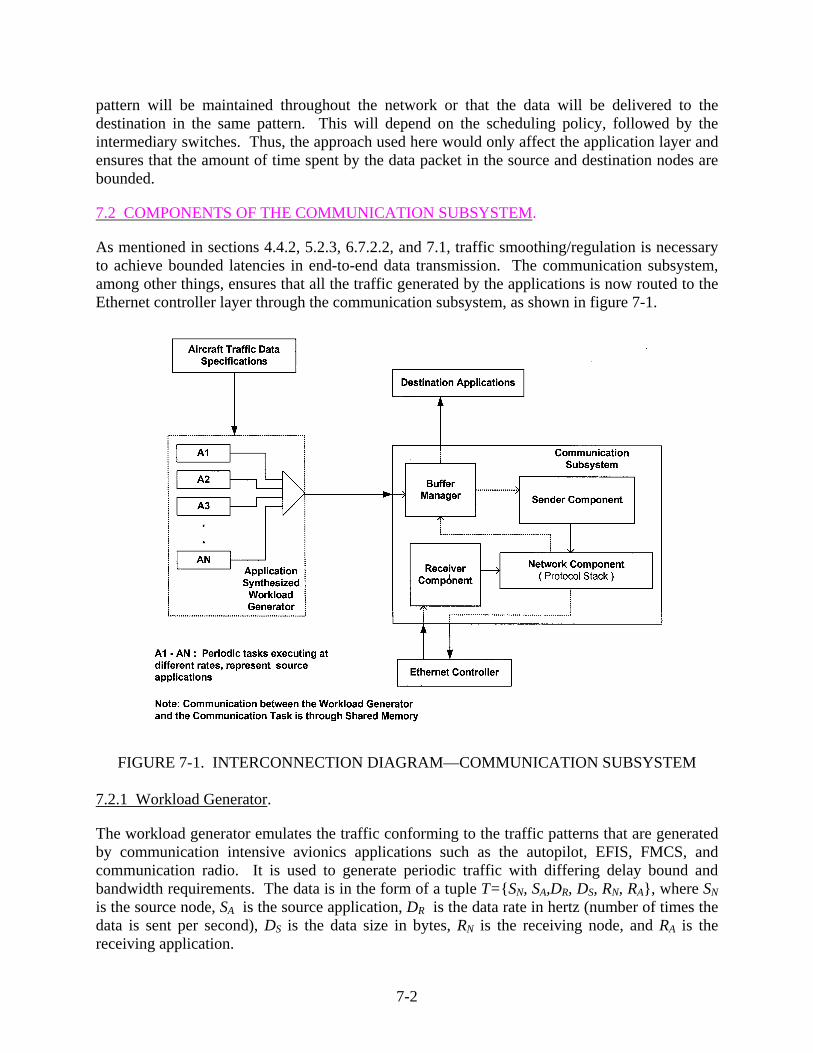
pattern will be maintained throughout the network or that the data will be delivered to the destination in the same pattern. This will depend on the scheduling policy, followed by the intermediary switches. Thus, the approach used here would only affect the application layer and ensures that the amount of time spent by the data packet in the source and destination nodes are bounded.
7.2 COMPONENTS OF THE COMMUNICATION SUBSYSTEM.
As mentioned in sections 4.4.2, 5.2.3, 6.7.2.2, and 7.1, traffic smoothing/regulation is necessary to achieve bounded latencies in end-to-end data transmission. The communication subsystem, among other things, ensures that all the traffic generated by the applications is now routed to the Ethernet controller layer through the communication subsystem, as shown in figure 7-1.
FIGURE 7-1. INTERCONNECTION DIAGRAM—COMMUNICATION SUBSYSTEM
7.2.1 Workload Generator.
The workload generator emulates the traffic conforming to the traffic patterns that are generated by communication intensive avionics applications such as the autopilot, EFIS, FMCS, and communication radio. It is used to generate periodic traffic with differing delay bound and bandwidth requirements. The data is in the form of a tuple T={SN, SA,DR, DS, RN, RA}, where SN is the source node, SA is the source application, DR is the data rate in hertz (number of times the data is sent per second), DS is the data size in bytes, RN is the receiving node, and RA is the receiving application.
7-2

7.2.2 Buffer Manager.
The buffer manager provides a collection of a set of APIs used to setup and teardown a guaranteed service connection and to perform read/write operations on them. The APIs have the same semantics as the standard UNIX socket library. Figure 7-2 depicts the APIs’ routines and their main functionality diagrammatically. Apart from the APIs, the buffer manager is responsible for maintaining the connection status and QoS-related parameters for all established flows in the system. This buffer manager is also referred to as connection manager in this report.
FIGURE 7-2. USER-LEVEL SOCKET LIBRARY
7.2.3 Sender Component.
The sender component is a periodic thread that constructs a list of packets eligible for transmission in a QoS-sensitive order during each of its executions and hands them over to the network component for protocol processing. The sender component is essentially the packet scheduler.
7.2.4 Network Component.
This is the standard communication protocol stack with routines for checksum computation, header processing, route discovery, and the like. The protocol stack used in the current implementation was optimized for traffic that does not need many of the standard services, such as IP options processing and IP forwarding. This has the overall effect of decreasing the stack processing latency and consequently improving the system throughput.
7-3

7.2.5 Receiver Component.
This module handles all the incoming packet’s postprotocol processing. It enqueues packets to the appropriate application buffer, which is then consumed by the application by invoking the API’s receive routine.
7.3 QUALITY OF SERVICE SPECIFICATIONS.
Applications specify their QoS requirements through the connect API routine. The format of the flow specifications is as specified in RFC 1363 [39] with modifications. The fields in the flow specification are described below:
• Version. This field is a 16-bit integer in Internet byte order. It is the version number of the flow specification.
• Maximum transmission unit. A 16-bit integer in Internet byte order, which is the maximum number of bytes in the largest possible packet to be transmitted over this flow.
• Token bucket rate. The token rate is the rate at which tokens (credits) are placed into an imaginary token bucket.
• Token bucket size. The token bucket size controls the maximum amount of data that the flow can send at the peak rate. More formally, if the token bucket size is B, and the token bucket rate is R, over any arbitrarily chosen interval T in the life of the flow, the amount of data that the flow sends cannot have exceeded B + (R * T) bytes. Note that the bucket size must be greater than or equal to the MTU size.
• Maximum transmission rate. The maximum transmission rate is the rate at which the bucket is emptied.
• End-to-end delay. It is the maximum time delay allowed between the transmission of a packet on the source and the reception of that packet on the destination for this flow.
• Maximum delay variation. It is the difference, in microseconds, between the maximum and minimum possible delay that a packet will experience.
• Loss sensitivity. This field indicates how sensitive the flow’s traffic is to losses. Loss sensitivity can be expressed in one of two ways: either as a number of losses of MTU-sized packets in an interval or simply as a value indicating a level of sensitivity.
• Quality of guarantee. This field is used to indicate different traffic classes. There are six legal values:
− 0x0: No guarantee is required (the host is simply expressing desired performance for the flow).
− 0x100: An imperfect guarantee is requested.
7-4
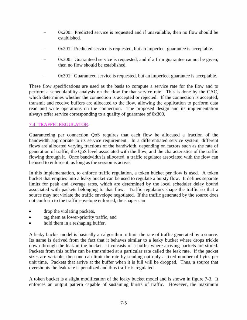
− 0x200: Predicted service is requested and if unavailable, then no flow should be established.
− 0x201: Predicted service is requested, but an imperfect guarantee is acceptable.
− 0x300: Guaranteed service is requested, and if a firm guarantee cannot be given, then no flow should be established.
− 0x301: Guaranteed service is requested, but an imperfect guarantee is acceptable.
These flow specifications are used as the basis to compute a service rate for the flow and to perform a schedulability analysis on the flow for that service rate. This is done by the CAC, which determines whether the connection is accepted or rejected. If the connection is accepted, transmit and receive buffers are allocated to the flow, allowing the application to perform data read and write operations on the connection. The proposed design and its implementation always offer service corresponding to a quality of guarantee of 0x300.
7.4 TRAFFIC REGULATOR.
Guaranteeing per connection QoS requires that each flow be allocated a fraction of the bandwidth appropriate to its service requirement. In a differentiated service system, different flows are allocated varying fractions of the bandwidth, depending on factors such as the rate of generation of traffic, the QoS level associated with the flow, and the characteristics of the traffic flowing through it. Once bandwidth is allocated, a traffic regulator associated with the flow can be used to enforce it, as long as the session is active.
In this implementation, to enforce traffic regulation, a token bucket per flow is used. A token bucket that empties into a leaky bucket can be used to regulate a bursty flow. It defines separate limits for peak and average rates, which are determined by the local scheduler delay bound associated with packets belonging to that flow. Traffic regulators shape the traffic so that a source may not violate the traffic envelope negotiated. If the traffic generated by the source does not conform to the traffic envelope enforced, the shaper can
• drop the violating packets, • tag them as lower-priority traffic, and • hold them in a reshaping buffer. A leaky bucket model is basically an algorithm to limit the rate of traffic generated by a source. Its name is derived from the fact that it behaves similar to a leaky bucket where drops trickle down through the leak in the bucket. It consists of a buffer where arriving packets are stored. Packets from this buffer can be transmitted at a particular rate called the leak rate. If the packet sizes are variable, then one can limit the rate by sending out only a fixed number of bytes per unit time. Packets that arrive at the buffer when it is full will be dropped. Thus, a source that overshoots the leak rate is penalized and thus traffic is regulated.
A token bucket is a slight modification of the leaky bucket model and is shown in figure 7-3. It enforces an output pattern capable of sustaining bursts of traffic. However, the maximum
7-5

sustainable burst size is limited and is equivalent to the depth of the token buffer. Here, the bucket holds tokens that are generated at the rate of one token every time units. Each token is equivalent to a certain number of bytes of data. At any given point of time, the amount of data that can be sent is equal to the sum of the weights (in bytes) of all the tokens in the token bucket.
FIGURE 7-3. THE TOKEN BUCKET MODEL For example, suppose it is desired to cause a particular flow to exhibit a peak rate of 4 Mbps and a maximum average rate of 2 Mbps. To implement this, the token bucket is configured to have a fill rate of 2 Mbps and the leaky bucket to have a leak rate of 4 Mbps. The fill rate guarantees that the average is no more than 2 Mbps and the leak rate guarantees that the peak is no more than 4 Mbps.
Figure 7-4 shows the fields in the connection descriptor that are concerned with the token bucket shaper.
FIGURE 7-4. CONNECTION DESCRIPTOR AND TOKEN BUCKET SHAPER STRUCTURES
When the application invokes the send routine, the message is first packetized. The b_contents field, which stands for token bucket contents, is updated each time a packet is to be sent. The
7-6

update is facilitated by the last_time field in struct shaper, which stores the last time of update of the bucket. The bucket is updated as follows
b_contents = (current_time – last_time) * serv_rt; The b_threshold field represents the token bucket depth. The token bucket must be able to hold at least one complete flow MTU. The token bucket is implemented using a watchdog timer facility available in VxWorks, the real-time operating system used for the development. Packetized data is compared to the token bucket contents in bytes to determine if it is eligible for transmission at that instant, or else it is enqueued in the application transmit buffer and a watchdog timer is started with a delay equal to the amount of time needed for a sufficient number of bytes to be accumulated in the token bucket. When the watchdog timer expires, the packet is dequeued from the application buffer and inserted at the appropriate position in the EDF-ordered list of eligible packets. At any given instant, the worst-case number of watchdog timers is equal to the number of backlogged connections. Watchdog timers are set only once for the packet at the head of a backlogged connection. Upon expiration, the associated buffer is inspected for the next packet, and if needed, the watchdog timer is set again.
In this implementation of the traffic shaper, nonconformant packets are buffered rather than policed. Prolonged violation of the flow specifications will, however, lead to buffer overflows.
7.5 PACKET SCHEDULER.
The EDF policy is the scheduling policy of choice for this prototype since it is known to be the optimal scheduling policy in terms of the schedulable region for a set of connections with given delay requirements [42]. The absolute deadlines of the data are embedded in the packets themselves, and these packets are ordered in a buffer with EDF fashion, i.e., with increasing orders of their deadlines. The scheme used here is more precisely called the NP-EDF since once a packet is chosen for processing, it is not interrupted in spite of another data packet of an earlier deadline entering the EDF buffer.
EDF is the optimal scheduling policy in terms of its schedulable region for the single-node case. The schedulable region of a policy is defined in terms of the delay bounds supported by it. This requires knowledge of the arrival curves of the connection at the input of the node. In the single-node case, this is equivalent to the arrival curve of the connection at the source node. However, for the multinode case, this no longer holds true. Interactions with cross traffic inside the network lead to distortions in the original traffic pattern. Such a scenario calls for traffic characterization inside the network, which is difficult at best. The rate-controlled EDF scheme proposed in references 24, 25, and 26, and used here, serves to extend the EDF implementation in the multinode case.
In EDF, packets are transmitted in increasing orders of their deadlines. This requires the insertion of a packet in a sorted queue. Any implementation of a sorting mechanism has a complexity O (log N) for insertion, where N is the number of packets in the queue. At very high transmission rates, this can lead to a lot of overhead. In this implementation, a batched EDF scheme is used where packets from several flows are aggregated in a single batch, which is transmitted periodically. Batching primarily serves to reduce the overhead involved in resorting
7-7

the queue upon every arrival of a packet. However, batching increases the latency experienced by a packet. The granularity of the batch determines this latency. Hence, the lowest delay supported by the system may be larger than approaches that do not make use of batching. This can lead to several connections being rejected by the CAC—leading to low throughput. There are many approximations of EDF (e.g., HOL with priority jumps and rotated priority queue) that can be used to obtain good throughput. The aim of this design approach is to provide deterministic service to real-time traffic without any significant degradation in the system throughput.
The EDF buffer is implemented as a binary search tree ordered on the basis of the local deadline of the packet. Computation of the local deadline is done as follows: bounddelaylocaltimeyeligibilitdeadlinelocal ____ += The eligibility time for a packet is its estimated arrival time, which depends on the arrival time of the previous packet and the service rate allocated to the packet’s flow. When application packets arrive, checks are made to see if there are enough tokens in the token bucket shaper, and if so, the local deadline of the packet is computed and inserted at the appropriate position in the binary search tree. Inserting a node into the binary search tree invokes the scheduler, if the number of nodes in the tree is equal to the batch size configured at system start up. In the extreme, the scheduler is invoked upon insertion of every packet. This leads to a work-conserving scheduler. The scheduler is also invoked periodically every Psched units of time. Upon invocation, the scheduler builds a list of deadline-ordered packets. All packets in the list are transmitted before the next invocation of the scheduler. The batch granularity and the scheduler period were computed with the intention of keeping the worst-case latency of the system below the lowest delay supported by the system. The scheduler period in this implementation is chosen as 1 ms. A hardware timer with an interrupt rate of 1 kHz is used for this purpose. The worst-case execution time of this thread is bounded since the worst-case batch size is also bounded.
7.6 NETWORK COMPONENT.
The network component is comprised of a lightweight communication protocol stack. The standard TCP/IP protocol suite with modifications has been used for purposes of interoperability. A XINU5 implementation of the network stack was ported to VxWorks® for the purpose of this prototype implementation. The following components of the XINU network stack are used.
• Transport layer protocols. In the protocol stack, UDP has been used at the transport layer instead of the TCP. UDP is connectionless; it adds no reliability, flow-control, or error-recovery functions to IP. Because of its simplicity, UDP headers contain fewer bytes and consume less network overhead than TCP. UDP is useful in situations where the reliability mechanisms of TCP are not necessary, such as cases where a higher-layer protocol might provide error and flow control. In a fully switched network (such as the one used for this architecture), all packets belonging to a flow can be configured to take
5 XINU is an operating system developed by the Department of Computer Science at Purdue University. It is freely
available at ftp://ftp.cs.purdue.edu/pub/Xinu/
7-8

the same path (switches) by statically configuring the switch ports. This is particularly important for the QoS-sensitive delay computations made by the CAC algorithm.
• Network layer protocols. The standard IP is used for addressing nodes in the system. Routing algorithms are among the main components of network layer processing. In this implementation, the routing table is statically configured at system boot up and consists primarily of route entries for all subnets with which the system interfaces. No other routes and routing updates are necessary since the network is fully switched. There are several advantages to this:
− Switching leads to lower latencies since it is implemented in hardware compared to routing that is implemented in software.
− A switched network increases security since packets going through switched connections are not seen by every node on the network. Only the sender and receiver nodes will handle these packets.
− Switching also leads to flexible configurations and is better suited to delay-sensitive traffic than router-based networks, besides being less expensive and easy to administer.
• Link layer protocols. As mentioned previously, ARP introduces nondeterminism in the IP packet transmission process. This is due to the variable time taken to resolve an IP address that has an entry in the ARP cache compared to one that does not. For supporting delay-guaranteed or real-time applications through IP over Ethernet, a static ARP cache is more suitable than a dynamic ARP cache. Static ARP takes advantage of avoiding ARP requests at the cost of losing flexible administration. In this implementation, ARP cache is statically configured. Every end-system maintains the IP to MAC address bindings for all other end-systems connected to it statically; this information is configured when the network is setup for the first time.
7.7 DATA FLOW IN COMMUNICATION SUBSYSTEM.
Figure 7-5 depicts the detailed design and data flow of the prototyped communication subsystem. A more detailed explanation of the design of each communication subsystem component is given in appendix A. It lists the individual thread properties, their functionality, and the interface mechanism with other threads in the subsystem.
7.8 END-TO-END MESSAGE DELAY.
Given a QoS requirement of a connection, messages of the connection must have a bounded end-to-end delay. As shown in figure 7-6, the end-to-end delay can be decomposed into source latency, receiver latency, and switch delay at each switch node. For instance, the local delay bound is computed by simply partitioning the end-to-end delay bound by (nhops + 1), where nhops is the number of intermediate nodes for this connection. The addition of one to nhops is to account for the source node. This assumes that the delay is evenly spread across the network, which is only possible if all switches are equally loaded. Different ratios can also be computed to simulate different loads on the switches, though it is not implemented here. The number of
7-9

hops information is available to the source node at the time of connection establishment, since the entire network is statically configured. A connection is accepted only if the system can guarantee to provide the connection with a minimal service that can enable packets belonging to that connection to meet their delay bounds at each transmission stage.
FIGURE 7-5. DATA FLOW DIAGRAM—COMMUNICATION SUBSYSTEM
7-10

FIGURE 7-6. END-TO-END DELAY MODEL
In this prototype, the communication subsystem at end-node is investigated, where the source latency includes the delays in the traffic shaper, protocol processing, frame transmission, and message scheduler. The first three delays can be measured based on the traffic characteristics of the connection and packet size, whereas the scheduling delay depends upon all existing connections at the source node.
To know whether a scheduling delay is acceptable or not at a source node, it is necessary to look into the properties of leaky bucket-constrained traffic sources. If the traffic entering the leaky bucket is said to have an arrival curve A(t), then the traffic output by the leaky bucket regulator is said to have an arrival curve A(t)= σ+ρ∗t, where σ is the maximum burst allowed at any given time and ρ is the rate at which packets from the leaky bucket are serviced. A(t) represents the total amount of traffic serviced by the leaky bucket at a time interval t. Now consider a delay d associated with each packet that passes through the regulator. The arrival curve of such a system can be given as A(t-d) (i.e., the amount of traffic serviced by the regulator by a time interval (t-d)) and A(t-d)=0 for t<d.
An important factor while determining the admission criteria is the schedulable region of the service discipline. The schedulable region of a service discipline is defined as the set of all delay bounds that can be guaranteed by that service discipline. The schedulable region of the NP-EDF policy consists of those delay bounds that satisfy the following constraints
7-11

(7-1) (7-2) (7-3) where
L = maximum packet length allowed by the system
R = link rate
d1 to dN = Set of delay bounds supported by the service discipline such that Nddd ≤≤ ......21 and di is the local scheduler delay for packets belonging to
connection i
Equation 7-1 checks if the lowest delay bound guaranteed by the system has a delay less than the transmit time of the maximum length packet in the system. Since this is a non-pre-emptive service discipline, this constraint must be checked. If this is not true, then it implies that the transmission of maximum length packets from any of the connections will cause a packet of some connection to miss the deadline.
Equation 7-2 checks if the amount of traffic to be transmitted by the system in the interval t is less than the maximum amount of traffic that can be transmitted by the system in that interval. This is for the case when the interval is less than the largest delay bound supported by the system.
Equation 7-3 is for the case when the interval is greater than the largest delay bound supported by the system.
To reduce the time complexity of the EDF implementation, the prototype architecture currently implements a batched EDF mode, where several packets in EDF order are grouped together and processed as a whole. Any new arrivals will have to wait until a batch is completely processed, even if the deadline of a new arrival is less than that of a packet already in the batch. This introduces an additional delay equal to the processing time of all packets in the largest sized batch that can be accommodated by the system. The worst-case batch size is dependent on the scheduler periodicity and on delays introduced by the task scheduling and IPC services of the operating system of the end-system node. The delays mentioned previously cause a significant reduction in the available bandwidth of the system. For the batched EDF policy, an additional constraint is given by
packetpacket TtB *)(
7-12

where BBpacket(t) is the worst-case backlog in the system in number of packets for the interval t, Tpacket is the worst-case protocol processing time per packet, and t is equal to the scheduler period . The above equation denotes the worst-case delay experience by a packet belonging to connection i due to the batching. For example, the worst-case delay due to batching with a link capacity of 10 Mbps and a worst-case per packet protocol processing time of 150 μs with a scheduler period of 1 ms would be about 3 ms, this is considering a packet size equal to the minimum Ethernet frame size.
schedP
7.9 TESTING OF THE PROTOTYPE COMMUNICATION SUBSYSTEM.
7.9.1 Testing Environment.
The test bed for evaluating the prototype implementation is depicted in figure 7-7. This test bed is simulating the actual avionics environment in the sense that the designed prototype has to handle the simulated avionics traffic patterns. Also, in the actual avionics environment, the hardware architecture of end-system node might differ, but it was felt that this test environment was sufficient enough to prove the behavior introduced by the communication subsystem to be deterministic within Ethernet databus framework.
FIGURE 7-7. TEST BED FOR THE SUBSYSTEM EVALUATION
As shown in the figure 7-7, Target 1 and Target 2 are Intel Xscale®-based targets running the VxWorks RTOS. Each of the target boards has two onboard Ethernet controllers and one PCI card-based network adapter. A single, OSI Layer-2 switch is connected between the targets. A copy of the communication subsystem is executed on each target. The ARP table on each of the targets is statically configured and contains an entry for each of the other targets in the test bed.
The switch configuration has only a single conductor from the targets to the switch; this setup can be used since all connections in the current architecture are unidirectional in nature. Flows
7-13

were only setup in one direction, from Target 1 to Target 2 for this evaluation. Hence, the traffic generator is executed only on Target 1. The bidirectional flows can be supported through a fully duplex, fully switched configuration.
A workload generator emulates the traffic generated by various communication-intensive avionics applications. It generates data based on the given rate. It can be configured to generate the traffic conforming or violating the flow specifications, depending on the following parameters:
• Local port for the source application. Port range (1025-65536).
• Priority of the traffic generator. Priority range (1-255).
Note: For testing purposes, communication subsystem threads have priority 51, 52, and 53. Hence, the traffic generator’s priority is varied to be either 100 or 49.
• Data generation rate. Specified in number of packets sent per second.
• Data size. Specified in number of bytes. It is the size of the payload without the packet header.
• Data send rate. This is the actual rate at which packets are sent. If the flow conforms to its flow specification, then the data send rate should be the same as the data generation rate; otherwise, for flow violation, the data send rate should be greater than the data generation rate, depending on the scale factor.
• Token bucket size. Maximum 10,000.
Note: For testing purposes, the token bucket size is varied to 1,500, 3,000, 6,000, and 10,000.
A hardware timer with a microsecond resolution is used to record the time stamps for the packet at its arrival and departure from the system in both the source and destination.
The delay parameters for the connection are measured as given below.
timestarttimeend
timestarttimeend
RRlatency_receiverSSlatency_source
latency_receiverlatency_sourcedelay_end_to_end
−−
−−
−=−=
+=
where
Sstart-time = Time at which the packet becomes eligible for transmission at the source node.
Send-time = Time at which the packet is transmitted by the source Ethernet controller.
7-14

Rstart-time = Time at which the packet was received by the low-level Ethernet driver at the receiver node.
Rend-time = Time at which the packet became available for consumption by the application at the receiver node.
The measured/computed values are stored in memory buffers on the target boards. After closing the connections, the statistics gathered in the data structures of the communication subsystem has to be sent from the target to the host machine. This can be done by a simple client-server (socket) interaction between the target and the host.
The statistics are analyzed to verify the feasibility of the communication architecture. This includes source latency analysis, guaranteed service validation, and end-to-end delay analysis. The results are discussed in detail in section 7.10.
7.9.2 Test Cases.
Functional testing is carried out on each component of the communication subsystem. The following is a brief list of test cases that checks system functionality in an error-prone environment. A more detailed explanation of each test category is given in appendix D.
7.9.2.1 Configuration Testing.
1. Check IP address configuration of the network interface. 2. Check ARP address mapping and addition and deletion of the entries. 3. Check routing table configuration. 4. Check configuration of number of hops information for each target in the network. 5. Check configuration of network parameters:
− Network buffer memory
− Maximum number of connections allowed
− Network interface initialization parameters (hardware address/broadcast address/ broadcast style)
6. Configuration of flow specifications 7.9.2.2 System Behavior Testing.
The purpose of this test category is to verify the functionality and behavior of each subsystem component in an erroneous environment. In this test category, the following components are verified:
• Socket Library
1. Socket calls must return error if system is not initialized.
7-15

2. Generate error for invalid socket specifications:
− Invalid IP address − Invalid port number
3. Generate error if maximum connections have been exceeded.
4. Generate error if socket is not opened.
5. Generate error for duplicate connect request.
6. Generate error if socket is not connected.
7. Generate error for invalid connect parameters:
− Invalid socket descriptor − Invalid flow specification
8. Generate error for invalid send or receive parameters:
− Null message − Invalid message size − Buffer space in receive is less than length of message
9. Generate errors if any system errors occur.
10. Generate timeout errors.
11. Generate errors for connection nonestablishment.
12. At receiving end, drop the packet if packet source does not match the session-sender’s IP address and port.
• Traffic Regulator
1. Check if packets of noncompliant traffic sources are being shaped.
2. Check effect of a single noncompliant flow on transmission of packets from other flows.
• Call Admission Controller
1. Generate error if aggregate service demand exceeds link capacity.
2. Generate error if local delay bound is less than the transmit delay for the packet.
3. Generate error if local delay is greater than the worst-case latency experienced by a packet due to the batched EDF policy.
7-16

4. Reject connection if the above conditions 1, 2, or 3 is true.
• Packet Scheduler
1. Generate error if protocol layers return error for the packet. 2. Check if packets are sent in deadline order. 3. Generate error if packet has missed its deadline.
• Protocol Stack
1. Check for data content correctness at receiving end. 2. Check if the packets are received by the intended recipient.
In case of corrupted packets or unintended recipients, packets are dropped by corresponding layer in the network stack.
• Error Generation and Flow Check
1. Generate errors for application input and output buffer overflows. 2. Check that the flow is terminated if condition 1 occurs.
7.9.2.3 Performance Evaluation.
1. Check that source latency is less than local delay.
2. Check that end-to-end latency requirements are satisfied.
3. Check that the communication subsystem is providing the guaranteed service, as per requested.
4. Check maximum number of number of connections allowed by the system (optional).
5. Measure the maximum throughput of the system (optional).
7.10 RESULTS.
The results of the guaranteed service implementation are evaluated by validating the performance of the various components that make up the communication subsystem, such as the token bucket shaper and the packet scheduler, against a mix of conformant and nonconformant traffic flows. The traffic generator opens a single flow with packets being generated at a given data rate. The generation rate is varied to violate the data rate specified by the application during connection request by 1, 10, 20, and 30 percent respectively. A zero percent scale factor implies that the flow is not violated. For each generation rate, the token bucket size is varied from the minimum allowable value of 1,500 bytes up to a maximum of 10,000 bytes. During each run, the delay experienced by the packet in the shaper and the scheduler, along with the latency in the source and the destination nodes, are recorded. All the single-flow data collected is done so without any cross traffic. The transit time from the source to the switch and from the switch to the destination is not considered in the end-to-end delay computation, and the time delays due to
7-17

the operating system on the end-system are also not accounted for.6 The single-flow test runs are conducted for specifications given in table 7-1. This flow specification is derived from actual traffic data collected from avionics application.
TABLE 7-1. FLOW SPECIFICATIONS
Parameter Value Data Rate 20 hertz End-to-End Delay 50 milliseconds Flow MTU 64 bytes Cross Traffic No Token Bucket Size 1,500-10,000 bytes Number of Hops 1 Number of Test Packets 2000 Scale Factors 0%, 1%, 10%, 20%, 30%
7.10.1 Source Latency Analysis.
Figure 7-8 is a plot of the average source latency for the different scale factors. The source latency is the time elapsed from the point at which the packet is injected into the flow to the point at which it is transmitted from the system. It can be observed that as the scale factor increases, the source latency also increases. This is due to the fact that the packets arriving earlier are delayed in the shaper. For lower-scale factors, the shaper delay is lower, and thus, the source latency is also lower. Also, the average source latency increases over time since the amount of backlog in the flow gradually builds up.
FIGURE 7-8. AVERAGE SOURCE LATENCY—VARIOUS SCALE FACTORS
6 In actual avionics systems, the transit time between the source to switch, switch to destination, and the time delays
due to the operating system on an end-system must be considered.
7-18

Figure 7-9 shows the average scheduler delay for various scale factors. As shown, the scheduler delay is almost constant for all scale factors.7 This shows that the delay experienced by packets is mainly due to the shaper. Also, the scheduler delay is much less than the local delay bound (i.e., 24.8 ms for 20-Hz data). The scheduler is work-conserving in nature, and thus, delay experienced by packets once they are out of the shaper is mainly system-induced.
FIGURE 7-9. AVERAGE SCHEDULER DELAY—VARIOUS SCALE FACTORS Note: The local delay bound of the system is computed as local delay = end-to-end delay ÷ (number of hops +1) – batch latency. Here, the number of hops = 1 (i.e., source node). Considering the batch latency to be 200 microseconds, for a 20-Hz data rate, local delay bound computes to 24.8 ms. Please refer to section 7.8 for details of the local delay computation.
7.10.2 Guaranteed Service Validation.
Tests are conducted to determine the guaranteed service properties of the system flows. Three connections, one each for 20-, 80-, and 40-Hz data, were established. Flow specifications for one of the flows are violated first and then for two. The effect of these flow violations on the remaining traffic is recorded by plotting a graph of their source latencies with and without the violations. Figure 7-10 shows the source latencies for all three flows without any flow violations.
In figures 7-11, 7-12, and 7-13, source latencies are analyzed where one of the flows is scaled by a factor of 10% (i.e., a traffic load greater than the specification). The plots show that the conforming connections have the preserved bandwidth and their source latency is not affected by the extra traffic of the violating connection.
7 The variation for the flow of 1% scale factor might have been induced due to low level system activities, which
might be dependent on the number of interrupts handled or the number of extraneous packets handled during this period. But this variation is too small, i.e., one-tenth of a millisecond, which can be considered insignificant enough, compared to the end-to-end delay of the system.
7-19

FIGURE 7-10. GUARANTEED SERVICE VALIDATION—NORMAL FLOWS
FIGURE 7-11. GUARANTEED SERVICE VALIDATION—VARIATION 1
(10% SCALE FACTOR)
7-20
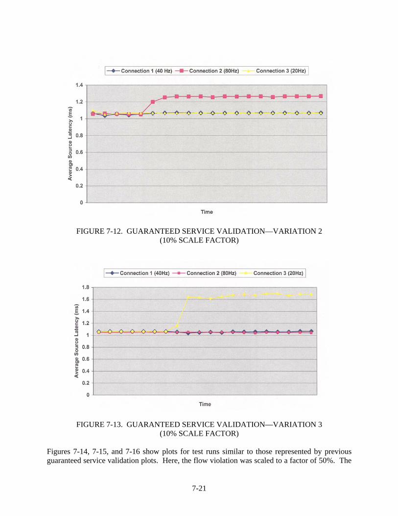
FIGURE 7-12. GUARANTEED SERVICE VALIDATION—VARIATION 2
(10% SCALE FACTOR)
FIGURE 7-13. GUARANTEED SERVICE VALIDATION—VARIATION 3
(10% SCALE FACTOR) Figures 7-14, 7-15, and 7-16 show plots for test runs similar to those represented by previous guaranteed service validation plots. Here, the flow violation was scaled to a factor of 50%. The
7-21

results observed were the same as the results obtained with a scale factor of 10%, in the sense that the conforming connections have the preserved bandwidth and their source latency is not affected by the extra traffic of the violating connection.
FIGURE 7-14. GUARANTEED SERVICE VALIDATION—VARIATION 1
(50% SCALE FACTOR)
FIGURE 7-15. GUARANTEED SERVICE VALIDATION—VARIATION 2
(50% SCALE FACTOR)
7-22

FIGURE 7-16. GUARANTEED SERVICE VALIDATION—VARIATION 3
(50% SCALE FACTOR) Figures 7-17, 7-18, and 7-19 show the average source latency plotted when two of the flows violate their flow specification. It can be seen that the violating flows experience a much larger latency, and the latency of the conforming one is not affected. This behavior shows that the flows are guaranteed service qualities independent of other flows as is required by the guaranteed service class of traffic.
FIGURE 7-17. GUARANTEED SERVICE VALIDATION—VARIATION 1
(TWO FLOW VIOLATIONS IN CONNECTIONS 1 AND 2)
7-23

FIGURE 7-18. GUARANTEED SERVICE VALIDATION—VARIATION 2
(TWO FLOW VIOLATIONS IN CONNECTIONS 2 AND 3)
FIGURE 7-19. GUARANTEED SERVICE VALIDATION—VARIATION 3
(TWO FLOW VIOLATIONS IN CONNECTIONS 1 AND 3) 7.10.3 End-to-End Delay Analysis.
Figure 7-20 shows the average values for end-to-end delay computed as a sum of the source and receiver latencies for a single flow. The flow specifications are violated by factors of 30, 20, 10, and 1 in percentages. As shown above, the end-to-end delay of packets is well below the
7-24

required end-to-end delay, which is equal to 50 ms. Also noted is the end-to-end delay does not vary with the flow rate.8 The source latency taken into consideration for the end-to-end delay computation is taken as the time elapsed from the point at which the packet became eligible for transmission to the point at which it is sent to the low-level driver for transmission on the medium. This graph shows that once packets become eligible, packets belonging to conforming/nonconforming flows are all scheduled at the same priority.
0
0.2
0.4
0.6
0.8
1
1.2
1.4
1.6
Tim
e (m
s)
Average End To End Delay Statistics
30% 20% 10% 1% 0%
FIGURE 7-20. AVERAGE END-TO-END DELAY—VARIOUS SCALE FACTORS
8 It can be seen in the graph that there is some variation in the end-to-end delay with the flow rate, but this variation
can be considered insignificant. This is because the above graph is constructed from several test runs, with each test run comprising of several thousand packets. The spikes indicate that the average delay was slightly different for a few test runs, which amounts to a very small percentage of packets when the aggregated number of packets sent is taken into account. Also, the resolution on the vertical axis is in milliseconds. This variation is of the order of a few tenths of a millisecond, which is insignificant compared to the end-to-end delay of the system.
7-25/7-26
8. SUMMARY AND FUTURE WORK.
In this report, the safety and certification issues of Ethernet-based aviation databuses were explored. The inherent nature of the Ethernet protocols can easily result in nondeterministic behavior and interference. To deploy Ethernet in flight-critical systems, all the safety concerns should be addressed.
In this research project, various nondeterministic factors in hardware and software components, which historically have prevented the use of Ethernet in avionics communication systems, were analyzed. The possible approaches to introduce determinism into such a system were investigated. A brief analysis of the traffic generated by a typical avionics system, comprising several avionics modules and applications, was presented. To support deterministic data delivery in Ethernet, a communication subsystem architecture was proposed. It included end-system design, switch architecture, and service discipline to integrate unicast and multicast traffic scheduling with guaranteed performance. For the qualification of Ethernet-based databuses, several evaluation criteria of the general aviation databuses were studied. The study focused on four criteria specific to Ethernet-based aviation databuses: safety, data integrity, performance, and configuration management. With the prototype design and by following these evaluation criteria, it was shown that the specific avionics requirements can be satisfied. Finally, with the example implementation and given test environment, the feasibility of using Ethernet-based databuses in avionics systems was demonstrated. The performance evaluation results show that by using the prototype communication subsystem, preliminary real-time deterministic support can be provided at communication end-systems of Ethernet-based databuses.
8.1 SUMMARY.
A summary of what was done in this study follows:
• The traffic, typically generated during the normal operation of an aircraft, was analyzed to understand its pattern. The effect of unicasting and multicasting in such an environment was identified.
• A number of factors influence determinism in a host system. A bottom-up analysis of these factors was carried out. Various nondeterministic aspects of the peripheral component interconnect-direct memory access architecture, used in Ethernet NIC, were identified and enumerated. Possible nondeterministic aspects of the software components, such as IP stack, were identified in the same way.
• Considering that the most effective approach for guaranteeing the performance of a traffic session is the use of a packet-based switch, the analysis focused on the QoS performance attributes of packet-switching networks. As part of this analysis, various switching architectures and scheduling disciplines were studied.
• A packet-scheduling algorithm, called EDR-RR, was proposed to satisfy the safety requirements of flight-critical applications. The algorithm is a RR-based discipline for OQ switches in packet-switching networks with fixed-length cells being the basic transmission and scheduling unit. Bandwidth reservation for a session at a switch is
8-1

carried out through the assignment of a number of cell slots in each frame for the session. The transferring order of cells in a frame is determined using a non-pre-emptive, nonidling EDF algorithm so that cells of a backlogged session in a frame are distributed as uniformly as possible. By analyzing the delay bound and buffer requirements of EDF-RR for both single-node and multiple-node cases, it has been shown that EDF-RR reveals high-performance characteristics in terms of safety requirements, e.g., determinism of real-time communications.
• A solution was proposed to integrate unicast and multicast traffic scheduling in packet-switching networks with guaranteed performance. A parallel-switching architecture, POQ, was introduced. POQ takes the advantage of both OQ and IQ switching architectures (i.e., nonblocking and speedup of switch fabric up to 1). This POQ architecture has the desired capability to support multicast traffic. To efficiently schedule multicast traffic within the POQ architecture, a hierarchical service discipline working on fixed-length cells (H-EDF-RR) is used. This is an extension of the EDF-RR discipline. Guaranteed performance for a POQ switch using the H-EDF-RR discipline was analyzed in terms of delay bound and buffer requirements while switching multicast traffic. Analytical results show that performance guarantees of multicast traffic are possible in this architecture.
• The generic communication architecture was developed to regulate, characterize, and perform resource reservation for the traffic generated by avionics applications. This was the result of an effort to bound per node delay of the traffic and to alleviate any buffer overruns at the intermediate switches by controlling the burstiness at the source node. The communication subsystem architecture for an end-node consisting of traffic regulator, call admission control mechanism, and dynamic priority packet scheduler was implemented.
• The general acceptance criteria for the aviation databus that were defined may be useful to evaluate future aviation databuses. Specifically, for the Ethernet-based aviation databuses, the four criteria are safety, data integrity, performance, and configuration management. Also, the proposed design of Ethernet-based aviation databus satisfies the acceptance criteria, considering the avionics application requirements.
• The design of the prototype communication subsystem was successfully validated through measurements of delay parameters, such as the source-receiver latencies and the end-to-end delay for a mix of conforming and nonconforming traffic flows.
• The performance evaluation results show that the preliminary real-time deterministic support can be provided on an Ethernet-based databus without any changes to the underlying protocols or the hardware (at least for the time aspects). The key to realizing this objective for this prototype is the use of a switched Ethernet topology along with traffic regulation, bandwidth reservation, and call admission control.
8-2

8.2 FUTURE WORK.
The prototype communication subsystem was designed to prove the feasibility of achieving real-time deterministic behavior while using the Ethernet-based aviation databus. Depending on the approaches studied in this report, various future research activities can be conducted.
The prototype design can be extended further with the consideration of scalability and fault tolerance capabilities. Also, the current test environment is based on the specific avionics application traffic. This test environment needs to be extended to handle the various traffic loads based on the specifications from several other avionics applications.
This research work focused on the Ethernet-based databus. Extension of the research activities can be carried out to evaluate other databuses, such as Controller Area Network, Gigabit Ethernet, and Asynchronous Transfer Mode, as avionics databuses. This will help in designing more efficient and cost-effective future avionics databuses.
8-3/8-4

9. REFERENCES.
1. Coulouris, G., Dollimore, J., and Kindberg, T., Distributed Systems: Concepts and Design, Second Edition, Addison-Wesley, London, 1994.
2. Chae, L., “Fast Ethernet: 100BaseT,” Network Magazine, December 1995.
3. Stallings, W., “Gigabit Ethernet,” Dr. Dobbs Journal, Vol. 25, issue 5, May 2000, pp. 34-37.
4. “Ethernet Physical and Data Link Layer Specification,” ARINC Specification 664 – Part 2, Aeronautical Radio Inc., Annapolis, MD, January 2003.
5. SAE/ARP-4761, “Guidelines and Methods for Conducting the Safety Assessment Process on Civil Airborne Systems and Equipment,” December 1996.
6. RTCA/DO-178B, “Software Considerations in Airborne Systems and Equipment Certification,” December 1992.
7. Intel, PCI specification V2.1.
8. Otanez Paul G., et al., “The Implications of Ethernet as a Control Network,” University of Michigan, Ann Arbor.
9. Court, R., “Real-Time Ethernet,” Computer Communications, 15(3), April 1992, pp. 198-201.
10. Venkatramani, C. and Chiueh, T., “Supporting Real-Time Traffic on Ethernet,” Proc. of Real-Time Systems Symposium, December 1994, pp. 282-286.
11. Venkatramani, C. and Chiueh, T., “Design and Implementation of a Real-Time Switch for Segmented Ethernet,” 1997.
12. Le Boudec, Jean-Yves, “Application of Network Calculus to Guaranteed Service Networks,” IEEE Transactions on Information Theory, Vol. 44, No. 3, May 1998.
13. Le Boudec, Jean-Yves and Thiran, Patrick, “Network Calculus: A Theory of Deterministic Queuing Systems for the Internet,” Springer, 2001.
14. Zhang, Hui, “Service Disciplines for Guaranteed Performance Service in Packet-Switching Networks,” Proceeding of the IEEE, Vol. 83, No. 10, October 1995.
15. Demeres, S. Keshav and Shenker, S., “Analysis and Simulation of a Fair Queueing Algorithm,” J. Internetworking Res. and Experience, October 1990, pp. 3-26.
16. Katavenis, M., et al., “Weighted Round-Robin Cell Multiplexing in a General-Purpose ATM Switch Chip,” IEEE Journal on Selected Areas in Communication, Vol. 9, No. 8, 1991.
9-1

17. Shreedhar, M. and Varghese, George, “Efficient Fair Queuing Using Deficit Round-Robin,” IEEE/ACM Transactions on Networking, Vol. 4, No. 3, June 1996.
18. Kanhere, Salil S., Sethu, Harish, and Parekh, Alpa B., “Fair and Efficient Packet Scheduling Using Elastic Round Robin,” IEEE Transactions on Parallel and Distributed Systems, Vol. 13, No. 3, March 2002.
19. Zhang, Lixia, “VirtualClock: A New Traffic Control Algorithm for Packet Switching Networks,” Proc. ACM SIGCOMM’90, Philadelphia, PA, September 1990, pp. 19-29.
20. Liu, C.L. and Layland, James W., “Scheduling Algorithms for Multiprogramming in a Hard-Real-Time Environment,” Journal of the Association for Computing Machinery, Vol. 20, No. 1, January 1973, pp. 46-61.
21. Bennet, J.C.R. and Zhang, H., “WF2Q: Worst-Case Fair Weighted Fair Queuing,” Proceeding of IEEE INFOCOM’96, CA, March 1996, pp. 120-128.
22. Ferrari, D. and Verma, D., “A Scheme for Real-Time Channel-Establishment in Wide Area Networks,” IEEE Journal on Selected Areas in Communication, April 1990.
23. Liu, Deming and Lee, Yann-Hang, “An Efficient Scheduling Discipline for Packet Switching Networks Using Earliest Deadline First Round Robin,” submitted to ICDCS 2003.
24. Zhang, H. and Ferrari, D., “Rate-Controlled Service Disciplines,” Jour. High Speed Networks, 1994, pp. 482-501.
25. Geogradis, L., Guerin, R., Peris, V., and Sivarajan, K., “Efficient Network QoS Provisioning Based on per Node Traffic Shaping,” IEEE/ACM Trans. Networking, August 1996, pp. 482-501.
26. Chiussi, Fabio M. and Sivaraman, Vijay, “Achieving High Utilization in Guaranteed Service Networks Using Earliest-Deadline-First Scheduling,” Proc. of IEEE/IFIP IWQoS’98: Sixth International Workshop on Quality of Service, Napa, California, USA, May 1998, pp. 209-217.
27. Guo, Ming-Huang and Chang, Ruay-Shiung, “Multicast ATM Switches: Survey and Performance Evaluation,” SIGCOMM Computer Communication Review, Vol. 28, No. 2, April 1998.
28. Marsan, M. Ajmone, Bianco, A., et al., “On the Throughput of Input-Queued Cell-Based Switches With Multicast Traffic,” INFOCOM 2001, IEEE Proceedings, Vol. 3, 2001, pp. 1664-1672.
29. Karlin, Scott and Peterson, Larry, “Maximum Packet Rates for Full-Duplex Ethernet,” Department of Computer Science, Princeton University Technical Report TR–645–02, February 14, 2002.
9-2

30. Chuang, Shang-Tse, Goel, Ashish, et al., “Matching Output Queueing With a Combined Input/Output-Queued Switch,” IEEE Journal on Selected Areas in Communications, Vol. 17, No. 6, June 1999, pp. 1030-1039.
31. Chen, Xing and Hayes, Jeremiah F., “Access Control in Multicast Packet Switching,” IEEE/ACM Trans. Networking, Vol. 1, December 1993, pp. 638-649.
32. Hui, Joseph Y. and Renner, Thomas, “Queueing Strategies for Multicast Packet Switching,” in Proc. IEEE Globecom, San Diego, CA, 1990, pp. 1431-1437.
33. Liu, Deming and Lee, Yann-Hang, “An Efficient Design for Scheduling Real-Time Multicast Traffic,” submitted to RTCSA 2003.
34. Intel Corporation, 82559 Fast Ethernet Multifunction PCI/Cardbus Controller Datasheet.
35. Liu, Zhen and Righter, Rhonda, “Scheduling Multicast Input-Queued Switches,” Journal of Scheduling, Vol. 2, 1999, pp. 99-114.
36. FAA CAST-16 Position Paper, “Databus Evaluation Criteria,” February 2003 http://www.faa.gov/aircraft/air_cert/design_approvals/air_software/ (Refer to CAST page).
37. FAA Order 8110.4B “Type Certification,” 24 April 2000. http://www.airweb.faa.gov/Regulatory_and_Guidance_Library/rgOrders.nsf/EA40C6FBF194E490D86256F8E0076ACB2?Open Document.
38. FAA Aircraft Certification Design Approvals: Original Design Approval Process “The FAA and Industry Guide to Product Certification,” Second Edition, September 2004. http://www.faa.gov/aircraft/air_cert/design_approvals/media/CPI_guide_IT.pdf.
39. RFC-1363 “A Proposed Flow Specification,” Internet Engineering Task Force, September 1992.
40. RFC-2215 “General Characterization Parameters for Integrated Service Network Elements,” Internet Engineering Task Force, September 1997.
41. “Avionics Application Software Standard Interface” ARINC Specification 653, Aeronautical Radio Inc., Annapolis, MD, January 1997.
42. Chiussi, Fabio M. and Sivaram, Vijay, “Achieving High Utilization in Guaranteed Services Networks Using Early-Deadline-First Scheduling,” High Speed Networks Research Department, Bell Labs, Lucent Technologies.
9-3/9-4
10. RELATED DOCUMENTATION.
Adaptec, AIC-6915 Ethernet LAN Controller Programmer’s Manual.
Albrecht, A.R. and Thaler, P.A., “Introduction to 100VG-AnyLAN and the IEEE 802.12 Local Area Network Standard,” Hewlett-Packard Journal, 46(4), August 1995.
“Backplane Databus,” ARINC Specification 659, Aeronautical Radio Inc., Annapolis, MD, December 1993.
Chou, C.C. and Shin, K.G., “Statistical Real-Time Channels on Multi-Access Networks,” IEEE Trans. on Parallel and Distributed Systems, 8(8), August 1997, pp. 769-780.
Golestani, S. Jamaloddin, “A Self-Clocked Fair Queueing Scheme for Broadband Applications,” Proc. IEEE INFOCOM’94, Toronto, CA, June 1994, pp. 636-646.
Hayes, Jeremiah F., Breault, Richard, et al., “Performance Analysis of a Multicast Switch,” IEEE Transactions on Communications, Vol. 39, No. 4, April 1991, pp. 581-587.
Kim, Daeyoung, Doh, Yoonmee, and Lee, Yann-Hang, “Table Driven Proportional Access Based Real-Time Ethernet for Safety-Critical Real-Time Systems,” accepted for publication in IEEE 2001 Pacific Rim International Symposium on Dependable Computing, December 2001.
Kweon, Seok-Kyu and Shin, Kang G., “Achieving Real-Time Communication Over Ethernet With Adaptive Traffic Smoothing,” Real-Time Computing Laboratory, Department of Electrical Engineering and Computer Science, The University of Michigan, Ann Arbor, MI 48109-2122. Gary Workman General Motors Tech Center, Warren, MI 48090-9040.
Lee, Y.H., Kim, D., Younis, M., Zhou, J., and McElroy, J., “Resource Scheduling in Dependable Integrated Modular Avionics,” Proc. of IEEE/IFIP International Conference on Dependable Systems and Networks, 2000, pp. 14-23.
National Instruments, “Doing PCI Right (The Advantages of MITE-Based Data Acquisition),” August 1997.
Open DeviceNet Vendor Association, “ControlNet International, Industrial Ethernet Association,” EtherNet/IP Developer Recommendations White Paper, May 2001.
Parekh, Abhay K. and Gallager, Robbert G., “A Generalized Processor Sharing Approach to Flow Control in Integrated Services Networks: the Single-Node Case,” IEEE/ACM Transactions on Networking, Vol. 1, No. 3, June 1993.
RadiSys Corporation, “Determinism and the PC Architecture (Applying PC Hardware to Real-Time Applications),” July 1998.
Scottis, Marios G., Krunz, Marwan, and Liu, Max M.-K, “Enhancing the PCI Bus to Support Real-Time Streams,” Integrate Technology Express, INC., Santa Clara, CA 95051.
10-1

Sivaram, Rajeev, Stunkel, Craig B., et al., “HIPIQS: a High-Performance Switch Architecture Using Input Queuing,” IEEE Transactions on Parallel and Distributed Systems, Vol. 13, No. 3, March 2002, pp. 275-289.
Stankovic, John A., Spuri, Marco, et al., Deadline Scheduling for Real-Time Systems: EDF and Related Algorithms, Kluwer Academic Publishers, 1998.
Tamir, Yuval and Frazier, Gregory L., “Dynamically-Allocated Multi-Queue Buffers for VLSI Communication Switches,” IEEE Transactions on Computers, Vol. 41, No. 6, June 1992, pp. 725-737.
Venkatramani, C. and Chiueh, T., “Design, Implementation and Evaluation of a Software-Based Real-Time Ethernet Protocol,” ACM SIGCOMM 95, 1995.
Zhang, Hui, “Service Disciplines for Guaranteed Performance Service in Packet-Switching Networks,” Proceeding of the IEEE, Vol. 83, No. 10, October 1995, pp. 1374-1396.
10-2

11. GLOSSARY.
This section provides key definitions and acronyms used throughout the report. ADS-B—Automatic Dependent Surveillance Broadcast equipped aircraft and vehicles automatically broadcast important information via data links, such as latitude and longitude, velocity, altitude, heading and identification, as determined by the avionics onboard and the Global Navigation Satellite System.
API—Application Program Interface. It is the interface provided by the system through which application can communicate.
AppleTalk—It is a proprietary network protocol suite developed by Apple Computer that can be used by both Apple and non-Apple computers for communication and sharing or resources such as printers and file servers. AppleTalk can be run over Apple’s twisted-pair wiring (LocalTalk) or over faster Ethernet (EtherTalk) wiring.
ARP—Address Resolution Protocol. The term address resolution refers to the process of finding an address of a computer in a network. The address is resolved using a protocol in which a piece of information is sent by a client process executing on the local computer to a server process executing on a remote computer. The information received by the server allows the server to uniquely identify the network system for which the address was required and, therefore, to provide the required address. The address resolution procedure is completed when the client receives a response from the server containing the required address.
ATM—Asynchronous Transfer Mode. A cell-based data transfer technique in which channel demand determines packet allocation. ATM offers fast packet technology, real-time, demand-led switching for efficient use of network resources. It is a flexible multiplexing and switching technique, which provides variable bandwidth for local area and wide area networks. Unlike ordinary synchronous configurations, ATM permits flexible allocation of available bandwidth for data, voice, images, and video. ATM uses a scalable architecture, making it easily upgradable; it allows a virtually unlimited number of users to have dedicated, high-speed connections with high-performance network servers.
CA—Central Arbiter. Initiators (devices) arbitrate for ownership of the bus by asserting a REQ# signal to a central arbiter. The arbiter grants ownership of the bus by asserting the GNT# signal. REQ# and GNT# are unique on a per slot basis allowing the arbiter to implement a bus fairness algorithm. Arbitration in PCI is hidden in the sense that it does not consume clock cycles. The current initiator’s bus transfers are overlapped with the arbitration process that determines the next owner of the bus.
CAN—Controller Area Network. CAN is a serial communications protocol developed by Bosch for the automotive industry. It is suited for networking devices such as controllers, sensors, and actuators within a system. The serial bus itself is a symmetric or asymmetric two-wire circuit, which may be screened or unscreened. The purpose of using CAN is to enable any station to communicate with any other station without putting too great a load on the controller computer.
CBR—Constant Bit Rate. Refers to the rate of bits received or transferred as being constant.
11-1
COTS—Commercial-Off-The-Shelf. Refers to a set of products that are commercially available for integration into larger systems as its elements.
CPU—Central Processing Unit. The central processing unit, or CPU, is a dated term synonymous with processor, microprocessor, or chip. To anthropomorphize computers for a moment, the processor is the machine’s brain. It takes in instructions, processes them, and pumps out responses.
CSMA/CD—Carrier Sense Multiple Access/Collision Detection. CSMA/CD is the protocol for carrier transmission access in Ethernet networks. On Ethernet, any device can try to send a frame at any time. Each device senses whether the line is idle and, therefore, available to be used. If it is idle, the device begins to transmit its first frame. If another device has tried to send at the same time, a collision is said to occur and the frames are discarded. Each device then waits a random amount of time and retries until it is successful in getting its transmission sent.
DEOS—Digital Engine Operating System. Refers to Honeywell’s RTOS for avionics applications.
DECnet—A set of networking protocols developed by Digital Equipment Corporation and used in its VAX family of computers to exchange messages and other data.
DMA—Direct Memory Access. Refers to the term used for a device/controller that transfers data to and from memory without complete intervention of the central processing unit.
EFIS—Electronic Flight Instrument System. Refers to one functional area system in the FMSS. A full EFIS combines traffic and resolution advisory information from different sources within the aircraft and provides the pilot with a unified display. This greatly simplifies the instrument scan and improves positional awareness.
EOI—End of Interrupt. Refers to an indicator that is used to indicate the end of interrupt.
FANS—Future Air Navigation System. FANS will provide the aviation industry with solutions to enhance safety and alleviate congestion, eliminating economic losses generated through delays. FANS is a concept that will meet the need of the civil aviation community over the next century, and it is also a systems concept to achieve this need, which is called the Communications, Navigation, Surveillance/Air Traffic Management (CNS/ATM) systems concept. The FANS CNS/ATM system concept involves a complex and interrelated set of technologies that is dependent mainly on satellites and was endorsed by the International Civil Aviation Organization in 1991. From the communications perspective, FANS will include communication protocols based on open systems interconnection (OSI) procedures and allowing the interconnection of airborne, ground, and air/ground networks, including local area networks (LANs), wide area networks (WANs), and radio links allowing a seamless, transparent, worldwide aeronautical digital data communications network. One of the possibilities for constituting these LANs and WANs will be Ethernet. FMCS—Flight Management System. Refers to a system that controls/monitors most of the flight-related parameters.
IEEE—Institute of Electrical and Electronic Engineers. An international standards development organization.
11-2

IFS—Interframe Spacing. Refers to the time duration used between frames of data.
IP—Internet Protocol. Refers to the protocol used in the network layer.
IPX—Internetwork Packet Exchange. IPX is a datagram protocol used for connectionless communications. It allows the exchange of message packets on an internetwork and is used by the Novell NetWare operating systems.
ISA—Industry Standard Architecture. The bus used in standard IBM-compatible PCs to provide power to add-in boards and communication between the add-in boards and to the motherboard (into which the boards plug).
ISR—Interrupt Service Routine. Routine that handles the interrupt.
LAN—Local Area Network. A LAN is a system that connects computers and other devices within the same physical proximity to form a network, usually with a wiring-based cabling scheme. LANs connect PCs and electronic office equipment, enabling users to communicate, share resources such as data storage and printers, and access remote hosts or other networks.
MAC—Media Access Control. Refers to the layer between the data-link and network layer in the standard OSI architecture.
MCA—Micro Channel Architecture. The 32-bit bus used in most IBM PS/2 PCs and the RS/6000 workstations.
MII—Medium Independent Interface. The MII is an optional set of electronics that provides a way to link the Ethernet medium access control functions in the network device with the physical layer (PHY) device that sends signals onto the network medium. An MII may optionally support both 10- and 100-Mbps operation, allowing suitably equipped network devices to connect to both 10BaseT and 100BaseT media segments.
NIC—Network Interface Card. A name for the LAN adapter (printed circuit board), installed in a PC that enables it to communicate over a LAN. The term is used more often by IBM customers and Token Ring people.
NP-Hard—The complexity class of decision problems that are intrinsically harder than those that can be solved by a nondeterministic Turing machine in polynomial time.
O-Notation—A theoretical measure of the execution of an algorithm, usually the time or memory needed, given the problem size n, which is usually the number of items. Informally, saying some equation f(n) = O(g(n)) means it is less than some constant multiple of g(n). The notation is read, “f of n is big oh of g of n.” A complexity measure equivalent to O(1), therefore, means that the execution of the algorithm takes constant time, whereas a complexity measure of O(n) means that execution time of the algorithm increases linearly with n.
OSI—Open System Interconnection. Suite of protocols and standards sponsored by the International Standard Organization (ISO) for data communications between otherwise incompatible computer systems.
11-3

PCI—Peripheral Component Interconnect. Intel’s local bus standard, introduced in 1992 (the first version) and 1993 (Release 2.0). PCI supports up to 16 physical slots—an addressing limitation, which normally will not be reached because of the electrical limitation of 10 loads (which will typically amount to three or four plug-in PCI cards) residing on each PCI bus. PCs can have two or more PCI buses, so there can be six or more PCI cards per PC.
PHY—Physical Layer. Refers to a layer in OSI.
QoS—Quality of Service. The network requirements (latency, maximum packet loss, etc.) to support a specific application.
RFC—Request for Comment. The RFC document series is a set of technical and organizational notes about the Internet (originally the ARPANET), which began in 1969. Memos in the RFC series discuss many aspects of computer networking, including protocols, procedures, programs, and concepts. The official specification documents of the IP suite that are defined by the Internet Engineering Task Force (IETF) and the Internet Engineering Steering Group (IESG) are recorded and published as standards’ track RFCs. An RFC can have several classes, including informational, experimental, proposed standard, and standard. Once published, RFCs are never modified or changed, only superceded.
STP—Shielded Twisted Pair. 150-ohm characteristic impedance, two pair, each pair individually foil shielded with another overall braid shield and used as a data communications cable. Specified by the IBM cabling system. Often used for Token Ring.
TCP—Transmission Control Protocol. Refers to the transport layer protocol in OSI.
UDP—User Datagram Protocol. Refers to the transport layer protocol in OSI.
UTP—Unshielded Twisted Pair. A popular type of cable for LANs and other in-building voice and data communications applications.
VLSI—Very Large-Scale Integration. Integrated circuits with 100,000 to 1 million transistors per chip.
11-4

APPENDIX A—RESULTS OF THE TRAFFIC ANALYSIS
This appendix presents the analysis of traffic data generated during normal operation of the aircraft. A.1 SYSTEMWIDE ANALYSIS.
This section is comprised of data tables extracted for a single collision domain (i.e., a bus) by aggregating the data for each node on that collision domain. A.1.1 BIT RATES.
Table A-1 shows the traffic generated in Mbps (bit rate) for the various protocols for point-to-point (unicast) and multipoint (multicast) communication modes obtained at the end of the analysis.
TABLE A-1. TRAFFIC GENERATED IN EXAMPLE AIRCRAFT APPLICATIONS
Data Transmission Protocol Media Access
Control Internet Protocol
Transmission Control Protocol
Aircraft Type Bus 1 Bus 2 Bus 1 Bus 2 Bus 1 Bus 2 Aircraft H 39 37 41 39 42 40 Aircraft P 55 51 59 54 60 56 Physical Aircraft H 32 30 33 32 34 33 Unicast
Physical Aircraft P 41 40 43 42 44 44 Aircraft H 5 5 5 5 5 5 Aircraft P 7 6 7 7 7 7 Physical Aircraft H 5 5 5 5 5 5 Multicast
Physical Aircraft P 7 6 7 7 7 7 A.1.2 PACKET LENGTH DISTRIBUTION.
Packet lengths were divided into the following ranges for the purpose of evaluating the above:
= 64 bytes (Minimum Ethernet Data Size) 64 bytes and < = 128 bytes 128 bytes and <= 512 bytes 512 bytes and <= 1024 bytes 1024 bytes and <= 1518 bytes (Maximum Ethernet Data Size)
The values in tables A-2 through A-5 are reported in packets per second (pps). Figures A-1 and A-2, A-3 and A-4, and A-5 and A-6 show average packet length distribution in unicast or multicast communication for MAC, IP, and TCP, respectively.
A-1

TABLE A-2. PACKET LENGTH DISTRIBUTION IN MAC POINT-TO-POINT COMMUNICATION (BUS 1)
Packet Length Groupings
Protocol Aircraft Type 64
(pps) 128
(pps) 512
(pps) 1024 (pps)
1518 (pps)
Aircraft H 49,768 4,206 5,030 230 100 Aircraft P 54,761 4,983 10,364 690 420 Physical Aircraft H 41,109 2,825 3,942 230 100
MAC
Physical Aircraft P 41,986 2,740 6,524 670 420 Aircraft H 45,153 8,062 5,769 250 100 Aircraft P 45,121 11,840 13,117 720 420 Physical Aircraft H 36,964 6,211 4,681 250 100
IP
Physical Aircraft P 34,152 9,441 7,627 700 420 Aircraft H 38,451 13,740 6,793 250 100 Aircraft P 38,725 17,627 13,686 760 420 Physical Aircraft H 31,022 11,573 5,261 250 100
TCP
Physical Aircraft P 29,205 14,089 7,886 740 420
TABLE A-3. PACKET LENGTH DISTRIBUTION IN POINT-TO-POINT COMMUNICATION (BUS 2)
Packet Length Groupings
Protocol Aircraft Type 64
(pps) 128
(pps) 512
(pps) 1024 (pps)
1518 (pps)
Aircraft H 46,782 3,965 4,870 230 100 Aircraft P 48,694 3,684 8,810 550 780 Physical Aircraft H 38,433 2,626 3,782 230 100
MAC
Physical Aircraft P 36,133 2,223 6,268 530 780 Aircraft H 43,012 6,980 5,605 250 100 Aircraft P 41,049 9,791 10,288 610 780 Physical Aircraft H 35,123 5,181 4,517 250 100
IP
Physical Aircraft P 30,179 7,507 6,878 590 780 Aircraft H 36,670 12,294 6,633 250 100 Aircraft P 35,203 15,028 10,897 610 780 Physical Aircraft H 29,501 10,219 5,101 250 100
TCP
Physical Aircraft P 25,802 11,585 7,177 590 780
A-2

TABLE A-4. PACKET LENGTH DISTRIBUTION IN MULTIPOINT COMMUNICATION (BUS 1)
Packet Length Groupings
Protocol Aircraft Type 64
(pps) 128
(pps) 512
(pps) 1024 (pps)
1518 (pps)
Aircraft H 7595 255 393 100 20 Aircraft P 8203 241 464 110 110 Physical Aircraft H 7595 255 393 100 20
MAC
Physical Aircraft P 8203 241 464 110 110 Aircraft H 7048 717 468 110 20 Aircraft P 7436 944 518 120 110 Physical Aircraft H 7048 717 468 110 20
IP
Physical Aircraft P 7436 944 518 120 110 Aircraft H 6251 1478 504 110 20 Aircraft P 6676 1682 530 130 110 Physical Aircraft H 6251 1478 504 110 20
TCP
Physical Aircraft P 6676 1682 530 130 110
TABLE A-5. PACKET LENGTH DISTRIBUTION IN MULTIPOINT COMMUNICATION (BUS 2)
Packet Length Groupings
Protocol Aircraft Type 64
(pps) 128
(pps) 512
(pps) 1024 (pps)
1518 (pps)
Aircraft H 7059 234 393 100 20 Aircraft P 6734 228 423 90 200 Physical Aircraft H 7059 234 393 100 20
MAC
Physical Aircraft P 6734 228 423 90 200 Aircraft H 6557 652 467 110 20 Aircraft P 6107 813 445 110 200 Physical Aircraft H 6557 652 467 110 20
IP
Physical Aircraft P 6107 813 445 110 200 Aircraft H 5780 1394 502 110 20 Aircraft P 5572 1326 467 110 200 Physical Aircraft H 5780 1394 502 110 20
TCP
Physical Aircraft P 5572 1326 467 110 200
A-3

0
10000
20000
30000
40000
50000
60000
64 128 512 1024 1518
Packet Length Groups
Num
ber o
f Pac
kets
(Pkt
s/s)
Aircraft H Aircraft P Physical Aircraft HPhysical Aircraft P
FIGURE A-1. AVERAGE PACKET LENGTH DISTRIBUTION IN MAC POINT-TO-POINT COMMUNICATION
0 1000 2000 3000 4000 5000 6000 7000 8000
64 128 512 1024 1518
Packet Length Groups
Num
ber o
f Pac
kets
(Pkt
s/s)
Aircraft H Aircraft P Physical Aircraft HPhysical Aircraft P
FIGURE A-2. AVERAGE PACKET LENGTH DISTRIBUTION IN MAC MULTIPOINT COMMUNICATION
A-4

0 5000
10000 15000 20000 25000 30000 35000 40000 45000 50000
64 128 512 1024 1518
Packet Length Groups
Num
ber o
f Pac
kets
(Pkt
s/s)
Aircraft H Aircraft P Physical Aircraft HPhysical Aircraft P
FIGURE A-3. AVERAGE PACKET LENGTH DISTRIBUTION IN IP POINT-TO-POINT COMMUNICATION
0 1000 2000 3000 4000 5000 6000 7000 8000
64 128 512 1024 1518
Packet Length Groups
Num
ber o
f Pac
kets
(Pkt
s/s)
Aircraft H Aircraft P Physical Aircraft HPhysical Aircraft P
FIGURE A-4. AVERAGE PACKET LENGTH DISTRIBUTION IN IP MULTIPOINT COMMUNICATION
A-5

0 5000
10000 15000 20000 25000 30000 35000 40000
64 128 512 1024 1518
Packet Length Groups
Num
ber o
f Pac
kets
(Pkt
s/s)
Aircraft H Aircraft P Physical Aircraft HPhysical Aircraft P
FIGURE A-5. AVERAGE PACKET LENGTH DISTRIBUTION IN TCP POINT-TO-POINT COMMUNICATION
0
1000
2000
3000
4000
5000
6000
7000
64 128 512 1024 1518
Packet Length Groups
Num
ber o
f Pac
kets
(Pkt
s/s)
Aircraft H Aircraft P Physical Aircraft HPhysical Aircraft P
FIGURE A-6. AVERAGE PACKET LENGTH DISTRIBUTION IN TCP MULTIPOINT COMMUNICATION
A.1.3 TRAFFIC GENERATION RATES.
Figures A-7 and A-8 and A-9 and A-10 show traffic generation rates and distribution in point-to-point and multipoint communication buses for aircraft H and P, respectively.
A-6

Rate (ms)
Traffic (Mbps)
12.5 14.62 25 8.57 50 6.80
100 7.93 200 1.57
1000 0.28
Systemwide Distribution of Traffic
36%
22%
17%
20%
4% 1% 12.5
25
50
100
200
1000
FIGURE A-7. TRAFFIC DISTRIBUTION IN MAC POINT-TO-POINT
COMMUNICATION (AIRCRAFT H)
Rate (ms)
Traffic (Mbps)
12.5 2.10 25 1.68 50 0.86
100 0.77 200 0.18
1000 0.03
Systemwide Distribution of Traffic
37%
30%
15%
14% 3% 1% 12.525501002001000
FIGURE A-8. TRAFFIC DISTRIBUTION IN MAC MULTIPOINT
COMMUNICATION (AIRCRAFT H)
Rate (ms)
Traffic (Mbps)
12.5 19.03 25 13.15 50 9.47
100 10.91 200 3.05 12.5 19.03
Systemwide Distribution of Traffic
33%
24%17%
20%
5% 1%12.525501002001000
FIGURE A-9. TRAFFIC DISTRIBUTION IN MAC POINT-TO-POINT
COMMUNICATION (AIRCRAFT P)
A-7
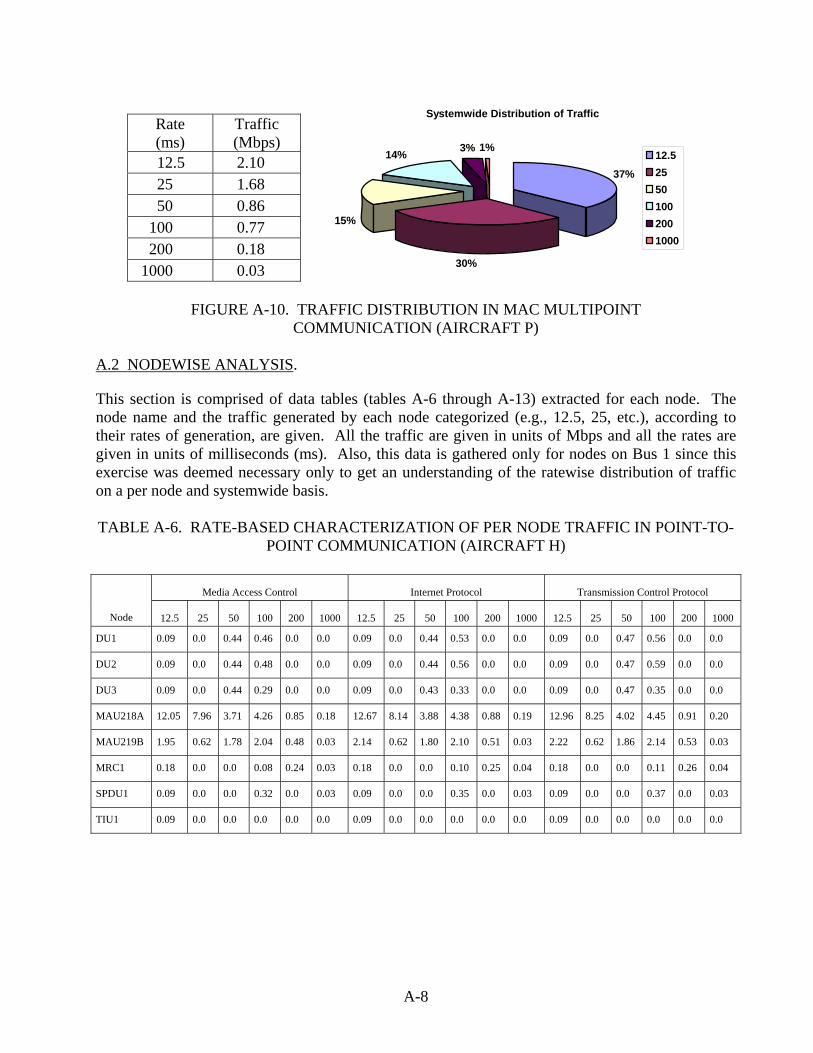
Rate (ms)
Traffic (Mbps)
12.5 2.10 25 1.68 50 0.86
100 0.77 200 0.18
1000 0.03
Systemwide Distribution of Traffic
37%
30%
15%
14% 3% 1%12.525501002001000
FIGURE A-10. TRAFFIC DISTRIBUTION IN MAC MULTIPOINT
COMMUNICATION (AIRCRAFT P) A.2 NODEWISE ANALYSIS.
This section is comprised of data tables (tables A-6 through A-13) extracted for each node. The node name and the traffic generated by each node categorized (e.g., 12.5, 25, etc.), according to their rates of generation, are given. All the traffic are given in units of Mbps and all the rates are given in units of milliseconds (ms). Also, this data is gathered only for nodes on Bus 1 since this exercise was deemed necessary only to get an understanding of the ratewise distribution of traffic on a per node and systemwide basis. TABLE A-6. RATE-BASED CHARACTERIZATION OF PER NODE TRAFFIC IN POINT-TO-
POINT COMMUNICATION (AIRCRAFT H)
Media Access Control Internet Protocol Transmission Control Protocol
Node 12.5 25 50 100 200 1000 12.5 25 50 100 200 1000 12.5 25 50 100 200 1000
DU1 0.09 0.0 0.44 0.46 0.0 0.0 0.09 0.0 0.44 0.53 0.0 0.0 0.09 0.0 0.47 0.56 0.0 0.0
DU2 0.09 0.0 0.44 0.48 0.0 0.0 0.09 0.0 0.44 0.56 0.0 0.0 0.09 0.0 0.47 0.59 0.0 0.0
DU3 0.09 0.0 0.44 0.29 0.0 0.0 0.09 0.0 0.43 0.33 0.0 0.0 0.09 0.0 0.47 0.35 0.0 0.0
MAU218A 12.05 7.96 3.71 4.26 0.85 0.18 12.67 8.14 3.88 4.38 0.88 0.19 12.96 8.25 4.02 4.45 0.91 0.20
MAU219B 1.95 0.62 1.78 2.04 0.48 0.03 2.14 0.62 1.80 2.10 0.51 0.03 2.22 0.62 1.86 2.14 0.53 0.03
MRC1 0.18 0.0 0.0 0.08 0.24 0.03 0.18 0.0 0.0 0.10 0.25 0.04 0.18 0.0 0.0 0.11 0.26 0.04
SPDU1 0.09 0.0 0.0 0.32 0.0 0.03 0.09 0.0 0.0 0.35 0.0 0.03 0.09 0.0 0.0 0.37 0.0 0.03
TIU1 0.09 0.0 0.0 0.0 0.0 0.0 0.09 0.0 0.0 0.0 0.0 0.0 0.09 0.0 0.0 0.0 0.0 0.0
A-8
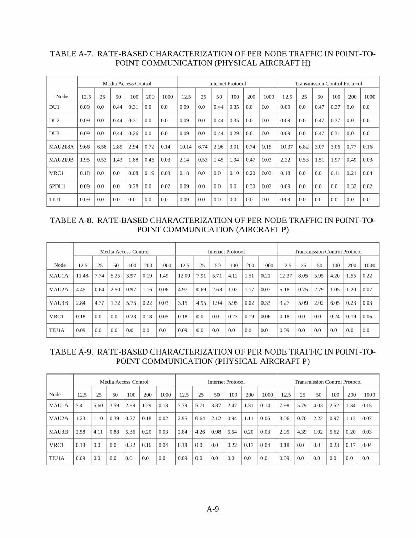
TABLE A-7. RATE-BASED CHARACTERIZATION OF PER NODE TRAFFIC IN POINT-TO-POINT COMMUNICATION (PHYSICAL AIRCRAFT H)
Media Access Control Internet Protocol Transmission Control Protocol
Node 12.5 25 50 100 200 1000 12.5 25 50 100 200 1000 12.5 25 50 100 200 1000
DU1 0.09 0.0 0.44 0.31 0.0 0.0 0.09 0.0 0.44 0.35 0.0 0.0 0.09 0.0 0.47 0.37 0.0 0.0
DU2 0.09 0.0 0.44 0.31 0.0 0.0 0.09 0.0 0.44 0.35 0.0 0.0 0.09 0.0 0.47 0.37 0.0 0.0
DU3 0.09 0.0 0.44 0.26 0.0 0.0 0.09 0.0 0.44 0.29 0.0 0.0 0.09 0.0 0.47 0.31 0.0 0.0
MAU218A 9.66 6.58 2.85 2.94 0.72 0.14 10.14 6.74 2.96 3.01 0.74 0.15 10.37 6.82 3.07 3.06 0.77 0.16
MAU219B 1.95 0.53 1.43 1.88 0.45 0.03 2.14 0.53 1.45 1.94 0.47 0.03 2.22 0.53 1.51 1.97 0.49 0.03
MRC1 0.18 0.0 0.0 0.08 0.19 0.03 0.18 0.0 0.0 0.10 0.20 0.03 0.18 0.0 0.0 0.11 0.21 0.04
SPDU1 0.09 0.0 0.0 0.28 0.0 0.02 0.09 0.0 0.0 0.0 0.30 0.02 0.09 0.0 0.0 0.0 0.32 0.02
TIU1 0.09 0.0 0.0 0.0 0.0 0.0 0.09 0.0 0.0 0.0 0.0 0.0 0.09 0.0 0.0 0.0 0.0 0.0
TABLE A-8. RATE-BASED CHARACTERIZATION OF PER NODE TRAFFIC IN POINT-TO-
POINT COMMUNICATION (AIRCRAFT P)
Media Access Control Internet Protocol Transmission Control Protocol
Node 12.5 25 50 100 200 1000 12.5 25 50 100 200 1000 12.5 25 50 100 200 1000
MAU1A 11.48 7.74 5.25 3.97 0.19 1.49 12.09 7.91 5.71 4.12 1.51 0.21 12.37 8.05 5.95 4.20 1.55 0.22
MAU2A 4.45 0.64 2.50 0.97 1.16 0.06 4.97 0.69 2.68 1.02 1.17 0.07 5.18 0.75 2.79 1.05 1.20 0.07
MAU3B 2.84 4.77 1.72 5.75 0.22 0.03 3.15 4.95 1.94 5.95 0.02 0.33 3.27 5.09 2.02 6.05 0.23 0.03
MRC1 0.18 0.0 0.0 0.23 0.18 0.05 0.18 0.0 0.0 0.23 0.19 0.06 0.18 0.0 0.0 0.24 0.19 0.06
TIU1A 0.09 0.0 0.0 0.0 0.0 0.0 0.09 0.0 0.0 0.0 0.0 0.0 0.09 0.0 0.0 0.0 0.0 0.0
TABLE A-9. RATE-BASED CHARACTERIZATION OF PER NODE TRAFFIC IN POINT-TO-
POINT COMMUNICATION (PHYSICAL AIRCRAFT P)
Media Access Control Internet Protocol Transmission Control Protocol
Node 12.5 25 50 100 200 1000 12.5 25 50 100 200 1000 12.5 25 50 100 200 1000
MAU1A 7.41 5.60 3.59 2.39 1.29 0.13 7.79 5.71 3.87 2.47 1.31 0.14 7.98 5.79 4.03 2.52 1.34 0.15
MAU2A 1.23 1.10 0.39 0.27 0.18 0.02 2.95 0.64 2.12 0.94 1.11 0.06 3.06 0.70 2.22 0.97 1.13 0.07
MAU3B 2.58 4.11 0.88 5.36 0.20 0.03 2.84 4.26 0.98 5.54 0.20 0.03 2.95 4.39 1.02 5.62 0.20 0.03
MRC1 0.18 0.0 0.0 0.22 0.16 0.04 0.18 0.0 0.0 0.22 0.17 0.04 0.18 0.0 0.0 0.23 0.17 0.04
TIU1A 0.09 0.0 0.0 0.0 0.0 0.0 0.09 0.0 0.0 0.0 0.0 0.0 0.09 0.0 0.0 0.0 0.0 0.0
A-9

TABLE A-10. RATE-BASED CHARACTERIZATION OF PER NODE TRAFFIC IN MULTIPOINT COMMUNICATION (AIRCRAFT H)
Media Access Control Internet Protocol Transmission Control Protocol
Node 12.5 25 50 100 200 1000 12.5 25 50 100 200 1000 12.5 25 50 100 200 1000
DU1 0.04 0.0 0.13 0.02 0.0 0.0 0.04 0.0 0.13 0.03 0.0 0.0 0.04 0.0 0.13 0.03 0.0 0.0
DU2 0.04 0.0 0.13 0.02 0.0 0.0 0.04 0.0 0.13 0.03 0.0 0.0 0.04 0.0 0.13 0.03 0.0 0.0
DU3 0.04 0.0 0.13 0.02 0.0 0.0 0.04 0.0 0.13 0.03 0.0 0.0 0.04 0.0 0.13 0.03 0.0 0.0
MAU218A 1.44 1.60 0.32 0.33 0.08 0.02 1.49 1.64 0.33 0.33 0.08 0.02 1.51 1.66 0.34 0.34 0.08 0.02
MAU219B 0.25 0.09 0.14 0.34 0.08 0.01 0.36 0.09 0.14 0.35 0.08 0.01 0.37 0.09 0.15 0.35 0.08 0.01
MRC1 0.09 0.0 0.0 0.01 0.03 0.01 0.09 0.0 0.0 0.01 0.03 0.01 0.09 0.0 0.0 0.01 0.03 0.01
SPDU1 0.04 0.0 0.0 0.03 0.0 0.0 0.04 0.0 0.0 0.03 0.0 0.0 0.04 0.0 0.0 0.03 0.0 0.0
TIU1 0.04 0.0 0.0 0.0. 0.0 0.0 0.04 0.0 0.0 0.0 0.0 0.0 0.04 0.0 0.0 0.0 0.0 0.0
TABLE A-11. RATE-BASED CHARACTERIZATION OF PER NODE TRAFFIC IN MULTIPOINT COMMUNICATION (PHYSICAL AIRCRAFT H)
Media Access Control Internet Protocol Transmission Control Protocol
Node 12.5 25 50 100 200 1000 12.5 25 50 100 200 1000 12.5 25 50 100 200 1000
DU1 0.04 0.0 0.13 0.02 0.0 0.0 0.04 0.0 0.13 0.03 0.0 0.0 0.04 0.0 0.13 0.03 0.0 0.0
DU2 0.04 0.0 0.13 0.02 0.0 0.0 0.04 0.0 0.13 0.03 0.0 0.0 0.04 0.0 0.13 0.03 0.0 0.0
DU3 0.04 0.0 0.13 0.02 0.0 0.0 0.04 0.0 0.13 0.03 0.0 0.0 0.04 0.0 0.13 0.03 0.0 0.0
MAU218A 1.44 1.60 0.32 0.33 0.08 0.02 1.49 1.64 0.33 0.33 0.08 0.02 1.51 1.66 0.34 0.34 0.08 0.02
MAU219B 0.35 0.09 0.14 0.34 0.08 0.01 0.36 0.09 0.14 0.35 0.08 0.01 0.37 0.09 0.15 0.35 0.08 0.01
MRC1 0.09 0.0 0.0 0.01 0.03 0.01 0.09 0.0 0.0 0.01 0.03 0.01 0.09 0.0 0.0 0.01 0.03 0.01
SPDU1 0.09 0.0 0.0 0.28 0.0 0.02 0.04 0.0 0.0 0.03 0.0 0.0 0.04 0.0 0.0 0.03 0.0 0.0
TIU1 0.04 0.0 0.0 0.0 0.0 0.0 0.04 0.0 0.0 0.0 0.0 0.0 0.04 0.0 0.0 0.0 0.0 0.0
A-10

TABLE A-12. RATE-BASED CHARACTERIZATION OF PER NODE TRAFFIC IN MULTIPOINT COMMUNICATION (AIRCRAFT P)
Media Access Control Internet Protocol Transmission Control Protocol
Node 12.5 25 50 100 200 1000 12.5 25 50 100 200 1000 12.5 25 50 100 200 1000
MAU1A 1.23 1.10 0.39 0.27 0.18 0.02 1.27 1.12 0.42 0.28 0.19 0.02 1.28 1.13 0.43 0.29 0.19 0.02
MAU2A 0.40 0.13 0.19 0.18 0.18 0.01 0.41 0.14 0.20 0.19 0.18 0.01 0.42 0.15 0.21 0.19 0.18 0.01
MAU3B 0.40 0.89 0.10 1.22 0.05 0.01 0.41 0.91 0.10 1.25 0.05 0.01 0.42 0.93 0.11 1.27 0.05 0.01
MRC1 0.09 0.0 0.0 0.02 0.02 0.0 0.09 0.0 0.0 0.02 0.02 0.0 0.09 0.0 0.0 0.02 0.02 0.0
TIU1A 0.04 0.0 0.0 0.0 0.0 0.0 0.04 0.0 0.0 0.0 0.0 0.0 0.04 0.0 0.0 0.0 0.0 0.0
TABLE A-13. RATE-BASED CHARACTERIZATION OF PER NODE TRAFFIC IN
MULTIPOINT COMMUNICATION (PHYSICAL AIRCRAFT P)
Media Access Control Internet Protocol Transmission Control Protocol
Node 12.5 25 50 100 200 1000 12.5 25 50 100 200 1000 12.5 25 50 100 200 1000
MAU1A 1.23 1.10 0.39 0.27 0.18 0.02 1.27 1.12 0.42 0.28 0.19 0.02 1.28 1.13 0.43 0.29 0.19 0.02
MAU2A 0.40 0.13 0.19 0.18 0.18 0.01 0.41 0.14 0.20 0.19 0.18 0.01 0.42 0.15 0.21 0.19 0.18 0.01
MAU3B 0.40 0.89 0.10 1.22 0.05 0.01 0.41 0.91 0.10 1.25 0.05 0.01 0.42 0.93 0.11 1.27 0.05 0.01
MRC1 0.18 0.0 0.0 0.22 0.16 0.04 0.09 0.0 0.0 0.02 0.02 0.0 0.09 0.0 0.0 0.02 0.02 0.0
TIU1A 0.04 0.0 0.0 0.0 0.0 0.0 0.04 0.0 0.0 0.0 0.0 0.0 0.04 0.0 0.0 0.0 0.0 0.0
A.2.1 GRAPHICAL REPRESENTATION OF THE NODEWISE STATISTICS.
Graphical representations of the data collected during the nodewise analysis, which are tabulated in tables A-6 through A-13, are shown in figures A-11 through A-14. The graphs are only drawn for two types of aircraft, namely, aircraft P and H, and it is done only for the multipoint and point-to-point use of the MAC protocol. This is so because the traffic generated by the above aircraft types is representative of the traffic generated by their counterparts among the physical aircraft types. Also, since there is little difference in the amount of traffic generated by the three different protocols (as illustrated by the tabulated data in the tables), it is sufficient to show the graphical representation for the below combinations to get an idea of the nodewise traffic flow in the aircrafts. The node names are represented on the horizontal axis and the amount of traffic is on the vertical axis. The vertical bars each represent a particular rate of generation of data by that node. The rates are expressed in units of milliseconds. A rate of 12.5 ms, for example, implies that data is sent out once every 12.5 ms. The traffic represented here is the sum total of all the traffic sent out by the different applications running on that node at that rate. Note: The node names DU1, DU2, DU3, MAU218A, MAU219B, MRC1, SPDU1, and TIU1 are taken as is from the aircraft traffic specifications provided by Honeywell Laboratories Inc.
A-11

0
1
2
3
4
5
6
7
8
9
10
Traf
fic (M
bps)
Nodes
12.5 0.09 0.09 0.09 9.66 1.95 0.18 0.09 0.09
25 0 0 0 6.58 0.53 0 0 0
50 0.44 0.44 0.44 2.85 1.43 0 0 0
100 0.31 0.31 0.26 2.94 1.88 0.08 0.28 0
200 0 0 0 0.72 0.45 0.19 0 0
1000 0 0 0 0.14 0.03 0.03 0.02 0
DU 1 DU 2 DU 3 MAU218A MAU219B MRC 1 SPDU 1 TIU 1
FIGURE A-11. RATE-BASED CHARACTERIZATION OF PER NODE TRAFFIC IN MAC
POINT-TO-POINT COMMUNICATION (AIRCRAFT H)
0
0.2
0.4
0.6
0.8
1
1.2
1.4
1.6
Traf
fic (M
bps)
Nodes
12.5 0.04 0.04 0.04 1.44 0.25 0.09 0.04 0.04
25 0 0 0 1.6 0.09 0 0 0
50 0.13 0.13 0.13 0.32 0.14 0 0 0
100 0.02 0.02 0.02 0.33 0.34 0.01 0.03 0
200 0 0 0 0.08 0.08 0.03 0 0
1000 0 0 0 0.02 0.01 0.01 0 0
DU 1 DU 2 DU 3 MAU218A MAU219B MRC 1 SPDU 1 TIU 1
FIGURE A-12. RATE-BASED CHARACTERIZATION OF PER NODE TRAFFIC IN MAC
MULTIPOINT COMMUNICATION (AIRCRAFT H)
A-12
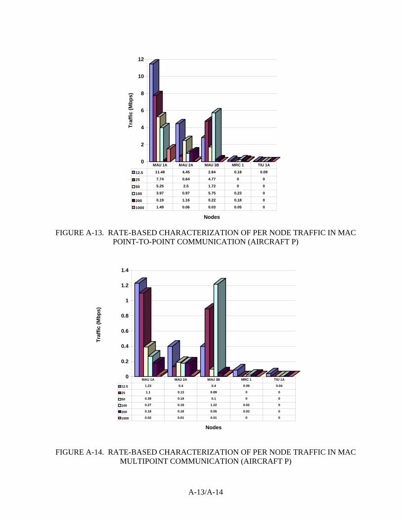
0
2
4
6
8
10
12
Traf
fic (M
bps)
Nodes
12.5 11.48 4.45 2.84 0.18 0.09
25 7.74 0.64 4.77 0 0
50 5.25 2.5 1.72 0 0
100 3.97 0.97 5.75 0.23 0
200 0.19 1.16 0.22 0.18 0
1000 1.49 0.06 0.03 0.05 0
MAU 1A MAU 2A MAU 3B MRC 1 TIU 1A
FIGURE A-13. RATE-BASED CHARACTERIZATION OF PER NODE TRAFFIC IN MAC
POINT-TO-POINT COMMUNICATION (AIRCRAFT P)
0
0.2
0.4
0.6
0.8
1
1.2
1.4
Traf
fic (M
bps)
Nodes
12.5 1.23 0.4 0.4 0.09 0.04
25 1.1 0.13 0.89 0 0
50 0.39 0.19 0.1 0 0
100 0.27 0.18 1.22 0.02 0
200 0.18 0.18 0.05 0.02 0
1000 0.02 0.01 0.01 0 0
MAU 1A MAU 2A MAU 3B MRC 1 TIU 1A
FIGURE A-14. RATE-BASED CHARACTERIZATION OF PER NODE TRAFFIC IN MAC MULTIPOINT COMMUNICATION (AIRCRAFT P)
A-13/A-14

APPENDIX B—DETAILED DESIGN OF THE COMMUNICATION SUBSYSTEM
This appendix provides a more detailed description of the functionality of each component of the communication subsystem introduced in section 7.2. Also, please refer to the data flow diagram shown in figure 7-5. B.1 BUFFER MANAGER.
The buffer manager has three components: connection manager, transmit buffer scanner, and receive buffer scanner. B.1.1 CONNECTION MANAGER.
This thread is used to establish the connection for the first time between a source and destination pair. It is invoked when the source application raises a signal to indicate that it wants to establish a connection. Alternately, since user diagram protocol (UDP) is planned to be used for connection establishment, a call to the UDP socket system call could also invoke this thread. The application wishing to setup the connection will provide its flow specification as part of its handshaking procedure. These flow specifications will be stored at a specific offset of the application-specific buffer. The application-specific buffer is implemented in shared memory with the buffer manager having read/write privileges over it. The flow specification provided by the application will be validated against the resources available, and depending on whether or not the requested quality of service (QoS) parameters can be met by the system at the existing conditions, the connection will either be setup or rejected. In either case, the concerned application will be informed of the consequences. In essence, the connection manager is intended to function as a call admission control. This thread will also be invoked at any such time that the application wishes to change its flow specifications. The application will provide the connection ID and the new set of specifications during such a call. For each flow specification accepted for the application, the connection manager allocates a transmit buffer and a receiver buffer. Note that these buffers are rate-based buffers and are not intended for any single-source destination pair. All connections (source destination pairs) pertaining to an application and with the same flow specifications are accommodated using a single buffer for that flow specification. Currently, the only determining factor in the flow specification is the rate of data generation. Classifications can also be made on other parameters such as the delay levels required or the priority of data. Also, the data generated with the shortest period will have the highest priority among all periodically generated data. Applications may also generate data with a specified static priority. This feature is used for sporadic data that is generated due to exceptions in the system behavior. A separate buffer based on the static priority will be created for all such data.
B-1

• Thread properties:
Type: Nonperiodic Period: None Execution Time: As long as it takes Invocation Mechanism: Signal/System call
• Interfaces:
Module/Thread Interprocess
Communications Mechanism Traffic Generator Shared Memory Buffer Scanner Shared Data Structure
B.1.2 TRANSMIT BUFFER SCANNER.
This thread is used to scan all the application-specific buffers in shared memory for any incoming data and copy them to the transmit buffers of the corresponding applications for further processing. Each data item in the shared memory is associated with its connection identifier, and the buffer scanner uses this connection identifier to identify the transmit buffer into which it needs to be copied. It allocates a structure, such as the ‘sk_buff’ packet structure in Linux, to hold the data. A 32-bit field containing the absolute time (system time) is filled in at this point. This field is later used to perform earliest deadline first (EDF) ordering of the data. This thread continually polls for incoming data every clock tick. To determine if new data is present in a buffer, the thread has to just read a single bit for each application buffer in the system. This bit is set by the application at the time of writing data. This will decease the overhead of the polling mechanism. The execution time of this thread is fixed. This ensures that system performance remains the same even when data is being generated in large amounts. If the buffer scanner fails in scanning all the buffers within the specified time period, it will resume at the next time period. This means to say that the buffer scanner follows a round-robin approach among those buffers that have new data. During each scan, exactly one data item from the application-specific buffer is copied into the corresponding transmit buffer before it moves on to the next buffer. This is in order to prevent higher-rate buffers from starving the lower-rate buffers, though it is possible that buffers are never dominated by a single rate. Buffers that could not be scanned (but contained new data) during the previous period are given higher priority for scanning during each period. Several data structures have to be maintained by the buffer scanner to this end. If there is no data to be copied, the buffer scanner returns immediately. If data were copied to the transmit buffers, it signals the sender component for further processing and returns. Each message copied successfully to the transmit buffer is marked as processed by the buffer manager (it has write privileges). This facilitates the application to reuse that buffer space. If a data item cannot be copied to the corresponding transmit buffer due to a buffer overrun, the concerned application is informed and it is up to the application to handle this situation. A
B-2
situation such as this will occur if the application forfeits its flow specification and generates data at a much faster rate than originally specified. In such a case, it is appropriate that the application be responsible for handling any exceptions arising out of it. The size of the transmit buffer will be dictated by the leaky bucket model implemented to regulate incoming traffic for each flow specification provided by the application. • Thread properties:
Type: Periodic Period: Single clock tick Execution Time: Fixed Invocation Mechanism: Auto
• Interfaces:
Module/Thread Interprocess
Communications Mechanism Source Application Shared Memory Sender Component Global Data Structure
B.1.3 RECEIVER BUFFER SCANNER.
This thread is the receive part of the above thread and essentially performs the same functions except on the receive buffers of the application. It periodically scans the receive buffers of all the applications using a similar approach as that of the transmit buffer scanner and copies the selected data into the application-specific shared memory area and deletes the corresponding packet in the scanned buffer. • Thread properties:
Type: Periodic Period: Single clock tick Execution Time: Fixed Invocation Mechanism: Auto
• Interfaces:
Module/Thread Interprocess
Communications Mechanism Destination Application Shared Memory
Receiver Component Global Data Structure
B-3

B.2 SENDER COMPONENT.
B.2.1 TRAFFIC REGULATOR/SORTER.
This thread is invoked by the buffer scanner component of the buffer manager at the end of its period if any new data were written into the transmit buffers. Alternately, this could also be a periodic thread if data is generated every time period. In such a situation, the overhead of signaling will prove costlier. The buffer scanner maintains a list of identifiers of buffers that were written into during that period, and this is used by the traffic regulator/sorter to scan the respective buffers and sort them. Validating the amount of data in each such buffer with that allowed by the leaky bucket for that connection does the rate limiting. This dictates whether the data packet in a given buffer will be chosen for EDF ordering during the given period. For this purpose, a data structure comprised of the leaky bucket parameters needs to be maintained for each such buffer. Thus, the rate of arrival of data into the EDF buffer is the aggregated peak rates of the per connection leaky buckets. Once the data is successfully validated against the leaky bucket parameters, its absolute time value is verified and the relative deadline is added to it to obtain the absolute deadline and it is inserted in the appropriate position in the EDF buffer. It is important to note here that the EDF buffer is not a physically separate memory area. It is a data structure with pointers to the memory locations of the various transmit buffers such that the data packets resident at those locations are in increasing orders of their deadlines. • Thread properties:
Type: Nonperiodic Period: None Execution Time: As long as it takes Invocation Mechanism: Signal
• Interfaces:
Module/Thread Interprocess
Communications Mechanism Buffer Scanner Global Data Structure Transmit Scheduler Shared Data Structure
B.2.2 TRANSMIT SCHEDULER.
This thread dequeues packets from the EDF buffer and hands them over to the network component for processing through the protocol stack. The buffer contains data packets ordered according to their absolute deadlines. The thread returns only after all the packets chosen by it during that time period are processed by the last layer of the protocol stack and are copied to the send queue of the Ethernet controller.
B-4

The amount of data chosen for network processing during each period depends on the transmission rate of the Ethernet controller. The send queue represents this rate and is capable of holding no more data during each period. After the data items are copied successfully to the send queue, the transmit scheduler suspends itself until the next time period. Thus, the execution time needed by the transmit scheduler is bounded by the transmission rate of the Ethernet controller. Note that this transmission rate is not a reflection on the capability of the Ethernet controller or the physical medium, rather this is the rate at which traffic from the corresponding node will be sent to achieve the desired end-to-end delay bounds. This rate is determined after analysis on the aggregated traffic on the system. • Thread properties:
Type: Periodic Period: Function of the transmission rate of the node. Execution Time: Fixed Invocation Mechanism: Auto
• Interfaces:
Module/Thread Interprocess
Communications Mechanism Traffic Regulator/Sorter Shared Data Structure Network Component Global Data Structure
B.3 NETWORK COMPONENT.
B.3.1 PROTOCOL STACK.
The stack is comprised of a set of functions implementing the standards specified by the transmission control protocol/internet protocol (TCP/IP) suite of protocols. Only the UDP, IP, data link, and memory access card protocols from the above suite are implemented. Also, only features necessary and sufficient for the current project are implemented in the selected protocols. These functions will run as part of the caller’s thread. Both the sender and the receiver components of the communication subsystem will make use of the stack. • Thread properties: Not applicable (N/A) • Interfaces:
Module/Thread Interprocess
Communications Mechanism Connection Manager Function Call Traffic Regulator/Sorter Global Data Structure Data Processor Global Data Structure
B-5

B.4 RECEIVER COMPONENT.
B.4.1 RECEIVER THREAD.
This is a function that runs as part of an interrupt context. The receiver thread is called by the interrupt service routine (ISR), which forms part of the Ethernet device driver, in response to the interrupt generated by the device on receiving a data packet. Since the receiver thread runs in the interrupt context with interrupts disabled, it needs to be fast and simple. All that the thead does is enqueue the data packet (copied by the ISR into a generic receive buffer in the system) in the queue for all incoming data packets in the system and check to see if the queue levels are within normal limits. Packets in the queue are in the order of their arrival at the network interface. If the queue is congested, it needs to trigger a throttling mechanism. The throttling mechanism is a way of flow control between the sender and the receiver nodes. It is used to avoid the swamping of the receiver node with multiple sender nodes. Here, the receiver should have buffers for each flow, i.e., each connection opened at the receiver end by the multiple sender nodes. The receiver should periodically send out flow control messages to indicate the amount of buffer space available at that point of time. The sender nodes should drain data based on these flow control messages, i.e., they should only drain an amount of data equal to the window advertised by the receiver and wait for another flow control message before sending out anymore data. The details of the throttling mechanisms have not been worked out since this is a prototype implementation that does not simulate a receiver being swamped with multiple senders. • Thread properties: N/A • Interfaces:
Module/Thread Interprocess
Communications Mechanism Ethernet Device Driver Function Call Data Processor Global Data Structure
B.4.2 DATA PROCESSOR.
This thread is responsible for all the processing done on the packet from the time it is received by the receiver thread up to the time it is ready to be delivered to its respective application. It periodically scans the incoming packets buffer built by the receiver thread and dequeues any unprocessed packets from it and passes it through the protocol stack and finally copies it to the receive buffer of the specified connection (this is not to be confused with the buffer in shared memory). Note, this buffer is rate-based and not for any specific source destination pair, and all data flowing through the same connection (meaning they all have the same flow specification) will have a single such buffer. All the processing happens in a single thread of control flow and the memory allocated to the data packet in the generic queue is then freed. This thread could be designed such that it is invoked by a signal (from receiver thread) only when there is data in the generic receive queue, but this is mostly in cases wherein the data received is not periodic in
B-6

nature. This thread has a fixed execution time for each period, and it processes as many data packets as possible within this time. • Thread properties:
Type: Periodic Period: Function of the average arrival rate of packets in
the node. Execution Time: Fixed Invocation Mechanism: Auto
• Interfaces:
Module/Thread Interprocess
Communications Mechanism Receiver Thread Shared Data Structure Network Component Global Data Structure
B-7/B-8

APPENDIX C—INTRODUCTION TO OUTPUT-QUEUED AND INPUT-QUEUED SWITCH ARCHITECTURES
This appendix provides an introduction to output-queued and input-queued switch architectures. C.1 OUTPUT-QUEUED SWITCHES.
In output-queued (OQ) switches, incoming packets are multiplexed over a fast bus or any other broadcast medium. Corresponding to each output link, there is an address filter that reads the bus, selects the packets destined for that output link, and copies those packets into the corresponding output buffer. Figure C-1 gives the structural diagram of an OQ switch. This design gives a better buffer utilization than the distributed buffer design, but a lower buffer utilization than the shared buffer design. The output buffer design is best suited for multicast traffic. Indeed, packets with multiple destination ports can be handled with virtually no additional complexity. The disadvantage is that it needs a high speedup factor. In other words, the switch fabric speed must be as large as the sum of the input link speeds.
.
.
.
Input Ports Crossbar Switching Fabric Output Buffers Output Ports
FIGURE C-1. OUTPUT QUEUE SWITCH STRUCTURE A design difficulty arises with output buffer switches. The number of packets that want to enter a given output buffer in one cell time can be as large as the number of input lines, say N. Accordingly, the number of input lines will be limited by the speed of the electronics used for the output buffers. To avoid this limitation, designers proposed to limit the number of packets that can be transferred into an output buffer to some value K < N. If there are more than K packets destined to the same output buffer in one packet time, then K of them are selected for transfer and the others are dropped. However, packet dropping may not be allowed in applications of hard real-time communications. To support multicasting, in addition to the N bus interfaces, the input buses are attached to, at most, M multicast modules specially designed to handle multicast packets [C-1]. Each multicast module has N inputs and one output. The inputs are the signals from the input interface modules. The output drives one of M bus wires as part of the arrangement for broadcasting to all the N bus interfaces. There are two methods to implement the multicast module: (1) using fast packet filter and (2) adding a copy network for packet duplication. When using a fast packet filter, once
C-1
a multicast packet is a winner from the knockout concentrator [C-1] that determines which multicast packet will obtain the opportunity of being buffered, it is buffered and then broadcast directly to all the bus interfaces without any modification. It is the packet filter’s responsibility to determine whether each arriving packet is destined for its output, and this has to be done in a few bit intervals so that no excessive delays are introduced. When using the approach of packet duplication, the incoming packets are selected through a particular filtering module such that only multicast packets are retrieved and forwarded to the packet duplicator. The duplicated packets are sent along the broadcast bus to the required bus interfaces. Both the fast packet filter and the packet duplicator approaches conform well to the original knockout switch architecture. Each guarantees the first-in, first-out packet sequence for the multicasting packets. As far as delay is concerned, the fast packet filter technique is clearly better, particularly so in cases where a multicast packet has a great number of destinations. Therefore, the fast packet filter is definitely favored in applications where the multicast traffic is heavy and involves a large number of simultaneous destinations for each packet. However, the packet duplicator method does not require distributed circuit tables and is somewhat easier to manage in terms of circuit updates. It thus seems to be more appropriate in situations where heavy multicast traffic is not demanded. Summary of OQ architecture: Advantages: • Absence of input contention points make it inherently nonblocking • Sophisticated quality of service (QoS) can be implemented by output schedulers • Easy to implement multicast Disadvantages: • Memory bandwidth required = N times line speed • Current memory technology limits the size of memory elements C.2 INPUT-QUEUED SWITCHES.
In input-queued (IQ) switches, as shown in figure C-2, packets arriving on each input line are placed into smoothing buffers, prior to placement on the correct output lines. In any given time slot, leading packets in all the buffers are sent to their output lines. If several buffer-leading packets contend for the same output, only one of them is selected according to contention scheme, while the rest remain in the buffers and contend again in the very next time slot. An IQ N-by-N switch requires N2 packet routing elements and N2 contention elements, which usually can all be synthesized on a single very large-scale integration chip. Each of the buffers, on the other hand, normally requires a separate chip, since RAM technology normally allows the contents of only one memory location to be read or written at a time. Therefore, the switch complexity, measured as the number of chips required for implementation, grows with N. An
C-2

advantage of an IQ switch is that a speedup of 1 suffices. In contrast with an OQ switch that requires high fabric speed, the speed of an IQ switch is the same as that of input or output lines. Input Ports Input Buffers Crossbar Switching Fabric Output Ports
.
.
.
FIGURE C-2. INPUT QUEUE SWITCH STRUCTURE The IQ switch suffers from an unfortunate phenomenon known as head of line blocking. The effect occurs when a packet in any given buffer is denied access to its output line, even though there are no other packets requiring the same output line, simply because the packet in the head of that buffer was blocked in contention for a totally different output. If the leading packet output line is under heavy contention, other packets in that buffer might have to wait for a relatively long period. In fact, the delay for a given packet may grow unbounded even for an offered load less than 100%. The IQ switch has some trouble in supporting packets intended for more than one output, i.e., multicasting. If a head packet is of this kind, it has to contend simultaneously for all the outputs it is intended for. Head of line blocking can be aggravated many times if the contention schemes are independent. Alternatively, the round-robin contention policy can be implemented in such a way that the rotating pointer is the same for all outputs at any given time; such an implementation guarantees that a packet does not stay in the queue for a longer time just because it is a multicast packet, but it leads to an even larger delay for the normal unicast packets. The IQ switch requires a lower speedup factor but also results in low throughput, whereas the OQ switch provides higher throughput but requires a higher speedup factor. To take advantage of both the approaches, a new crossbar switch structure, combined input output queuing (CIOQ), switch is proposed such that a compromise is made between these two. In this structure, buffers exist in both the input and output sides. Researchers have proved that the CIOQ switch can achieve 100% throughput for unicast traffic with a speedup factor of 2 [C-2]. Contrary to the case of unicast traffic, for which IQ switches can yield the same throughput as OQ switches, it is shown by experiments and analytical modeling that throughput limitations exist in IQ switches (including CIOQ switches) loaded with multicast traffic [C-3].
C-3

Summary of IQ (including virtual OQ and CIOQ) architecture:
Advantages:
• Memory bandwidth required is same as line speed.
Disadvantages:
• Crossbar blocking and optimal matching computation required
• Frequency and complexity of centralized arbitration does not scale with size and interface rates
• Arbitration determines observed bandwidth and difficult to guarantee switchwide QoS to individual flows
• Difficult to implement multicast
Since IQ switches are not inherently suitable for guaranteeing switchwide QoS for individual sessions, most scheduling algorithms in IQ switches is best-effort instead of hard real time [C-4 to C-6]. Occasionally, it is thought that iSLIP (an iterative round-robin scheduling algorithm for IQ switches) [C-6] is one of the innovative algorithms for IQ switches. Unfortunately, it only provides best-effort schedule rather than guaranteed performance. C.3 REFERENCES.
C-1. Guo, Ming-Huang and Chang, Ruay-Shiung, “Multicast ATM Switches: Survey and Performance Evaluation,” SIGCOMM Computer Communication Review, Vol. 28, No. 2, April 1998.
C-2. Chuang, Shang-Tse, Goel, Ashish, et al., “Matching Output Queueing With a Combined Input/Output-Queued Switch,” IEEE Journal on Selected Areas in Communications, Vol. 17, No. 6, June 1999, pp. 1030-1039.
C-3. Marsan, M. Ajmone, Bianco, A., et al., “On the Throughput of Input-Queued Cell-Based Switches With Multicast Traffic,” INFOCOM 2001, IEEE Proceedings, Vol. 3, 2001, pp. 1664-1672.
C-4. McKeown, Nick, “The iSLIP Scheduling Algorithm for Input-Queued Switches,” IEEE/ACM Transactions on Networking, Vol. 7, No. 2, April 1999, pp. 188-201.
C-5. Minkenberg, C., “Integrating Uincast and Multicast Traffic Scheduling in a Combined Input- and Output Queued Packet-Switching System,” Computer Communications and Networks 2000, Proceedings, Ninth International Conference, 2000, pp. 127-134.
C-6. Prabhakar, Balaji, McKeown, Nick, et al., “Multicast Scheduling for Input-Queued Switches,” IEEE Journal on Selected Areas in Communications, Vol. 15, No. 5, June 1997, pp. 855-866.
C-4

APPENDIX D—TEST PLAN
This appendix details the test categories mentioned in section 7.9.2. It explains each test category and its purpose. It also mentions how the system can be tested and verified for that specific category. Note that these testing and verification activities are independent of any target environment.
Test Category Section Test Category Test Purpose Test/Verification Activities
Following system configuration parameters should be verified: • IP address configuration of network
interfaces.
• ARP address mapping addition/ deletion.
• Routing table configuration (addition of default routes based on interface configuration): This is needed for selection of the correct interface for sending the packet based on its destination address.
• Configuration of number of hops information for each target in the network.
• Configuration of network parameters:
- Network buffer memory.
- Maximum number of connections allowed: This is a limit on the number of socket descriptors that can be stored.
• Network interface initialization parameters (hardware address/ broadcast address/broadcast style).
7.9.2.1 Configuration Testing
The purpose of this test category is to verify various system configuration parameters.
• Configuration of flow specifications.
D-1

Test
Category Section Test Category Test Purpose Test/Verification Activities
• Socket calls must return error if system is not initialized.
• Error should be generated for invalid socket specifications:
- Invalid IP address.
- Invalid port number, e.g., port is already in use or not within range.
• Error should be generated if maximum connections have been exceeded.
• Error should be generated if socket cannot be opened: This error can be generated by making socket library “Connect” call before “Socket” call.
• Error should be generated if duplicate “Connect” request appears.
• Error should be generated if socket is not connected: This error can be generated by making socket library “Send” or ”Receive” call before “Connect” call.
7.9.2.2 Socket Library
The purpose of this test category is to check the socket library behavior in an erroneous environment.
• Error should be generated if invalid parameters are passed to “Connect” call.
- Invalid socket descriptor.
- Invalid flow specification, e.g., flow MTU size is greater than the datagram size.
D-2

Test
Category Section Test Category Test Purpose Test/Verification Activities
• Error should be generated for invalid “Send” or “Receive” parameters
- Null message.
- Invalid message size, e.g., message size exceeds flow MTU.
• Buffer space in “Receive” call is less than length of message: (The system copies incomplete message, but it also returns error)
• System errors should be handled. System errors can be generated through memory crunch or any operating system-specific returned errors.
• Time-out errors should be handled, e.g., semaphores not acquired for socket calls within time-out period.
• Errors should be generated for connection nonestablishment e.g., connection refused by Call Admission Controller.
• Packet must get dropped at receiving end if packet source does not match session sender’s IP and port.
7.9.2.2 Traffic Regulator
The purpose of this test category is to check the Traffic Regulator behavior in an erroneous environment.
• Check if packets of noncompliant traffic sources are being shaped. To verify this, establish a connection with X as the packet generation rate, this can be specified by the peak rate field in the flow specs, then generate packets at rates greater than this and observe latencies experienced by packet belonging to the flow.
D-3

Test
Category Section Test Category Test Purpose Test/Verification Activities
• Check effect of a single noncompliant flow on transmission of packets from other flows. To verify this, compute source latencies for all flows before and after the designated flow starts violating its flow specs and compare them.
• Error should be generated if aggregate service demand exceeds link capacity: To verify this, create a system overload.
• Error should be generated if local delay bound is less than the transmit delay for the packet.
• Error should be generated if local delay is greater than the worst-case latency experienced by a packet due to the batched EDF policy.
7.9.2.2 Call Admission Controller
The purpose of this test category is to check the Call Admission Controller behavior in an erroneous environment.
• Connection must be rejected if any of above error conditions is true.
• Error should be generated if protocol layers return an error for the packet.
• Check if packets are sent in deadline order. To verify this, open a single connection and see that packets are sent in the order that they are sent, since packets sent later in the same flow have a later deadline, it is enough to verify that they are sent in FIFO order.
7.9.2.2 Packet Scheduler
The purpose of this test category is to check the Packet Scheduler behavior in an erroneous environment.
• Error should be generated if packet has missed its deadline.
D-4

Test Category Section Test Category Test Purpose Test/Verification Activities
• Check for data content correctness at receiving end. This can be verified using checksum computation.
7.9.2.2 Protocol Stack
The purpose of this test category is to check the Protocol Stack behavior in an erroneous environment.
• Check if the packets are received by the intended recipient only. This can be verified using recipient’s IP address and port.
• Errors should be generated for application input and output buffer overflows.
7.9.2.2 Error Generation and Flow Check
Other system behavior test cases.
• Check that flow is terminated if above error condition occurs.
• Check that source latency is less than local delay.
• Check that end-to-end latency is met.
• Check number of connections allowed (optional).
7.9.2.3 Performance Evaluation Testing
The purpose of this test category is to evaluate the average performance of the system in terms of latency and throughput.
• Throughput measurement (optional).
D-5/D-6