Safety & Instruction Manual M&P 15 Centerfire Rifles
56
Copyright © 2019 Smith & Wesson Inc. All rights reserved. 2100 Roosevelt Avenue • Springfield, MA 01104 1-800-331-0852 • Fax: 1-413-747-3317 www.smith-wesson.com Read the instructions and warnings in this manual CAREFULLY BEFORE using this firearm. Safety & Instruction Manual M&P ® 15 Centerfire Rifles
Transcript of Safety & Instruction Manual M&P 15 Centerfire Rifles

Copyright © 2019 Smith & Wesson Inc.All rights reserved.
2100 Roosevelt Avenue • Springfield, MA 011041-800-331-0852 • Fax: 1-413-747-3317
www.smith-wesson.com
Read the instructions andwarnings in this manual
CAREFULLY BEFOREusing this firearm.
Safety & Instruction Manual M&P®15 Centerfire Rifles

2
WARNING:READ THESE
INSTRUCTIONS AND WARNINGS CAREFULLY. BE SURE YOU UNDER-STAND THESE INSTRUCTIONS AND
WARNINGS BEFORE USING THIS FIREARM. FAILURE TO READ THESE
INSTRUCTIONS AND TO FOLLOW THESE WARNINGS MAY RESULT IN
SERIOUS INJURY OR DEATH TO YOU AND OTHERS AND DAMAGE TO PROPERTY.
THIS SAFETY & INSTRUCTIONMANUAL SHOULD ALWAYS
ACCOMPANY THIS FIREARM AND BE TRANSFERRED WITH IT UPON
CHANGE OF OWNERSHIP OR WHEN PRESENTED TO ANOTHER PERSON. A COPY OF THE SAFETY & INSTRUC-
TION MANUAL IS AvAILABLE FREE vIA DOWNLOAD AT
WWW.SMITH-WESSON.COM OR UPON REqUEST FROM:
SMITH & WESSON®
CUSTOMER SUPPORT CENTER2100 ROOSEvELT AvENUESPRINGFIELD, MA 01104
TEL.: 1-800-331-0852, ext. 4125E-mail: [email protected]
NOTE: The M&P®15 rifle, as sold by Smith & Wesson®, is a rifle. Changes to the configuration of the M&P®15 rifle by the end-user, including but not limited to, the addition of a barrel
less than 16˝ in length may subject the firearm to classification under the National Firearms Act, which imposes registration,
taxes, and other requirements on the owners of such firearms. It is your responsibility to comply with all Federal, State and Local Laws and regulations regarding the ownership or pos-
session of this firearm and any conversions or additions of any after-market accessories that you undertake.

3
YOUR SAFETY RESPONSIBILITIESSAFETY IS YOUR NUMBER ONE RESPONSIBILITY!
• At home, in the field, at the range, or anywhere, the first concern of every firearm owner should be safety. Apply the following safety rules in every situation, with any kind of fire-arm. If you feel uncertain about any operational aspects of your firearm, please contact Smith & Wesson at 1-800-331-0852, ext. 4125 before proceeding with its operation.
• If you are unfamiliar with firearms you should seek formal training before using your rifle.
WARNING: YOU MUST FOLLOW ALL OF THESE SAFETY RULES TO ENSURE THE SAFE USE OF YOUR FIREARM. THE FAILURE TO FOLLOW THE INSTRUCTIONS AND
WARNINGS IN THIS MANUAL COULD CAUSE SERIOUS PER-SONAL INJURY OR DEATH TO YOU OR OTHERS AND DAMAGE TO PROPERTY.
• As a firearm owner, you accept a demanding responsibility. How seriously you take this responsibility can be the difference between life and death. There is no excuse for careless or abu-sive handling of your firearm. At all times handle your firearm with intense respect for its power and potential danger.
TABLE OF CONTENTSYOUR SAFETY RESPONSIBILITIES ..................................... 3-6SAFE STORAGE AND TRANSPORTATION ........................... 7-8AMMUNITION ..................................................................... 9-11MODEL AND FEATURES IDENTIFICATION ............................ 12INSPECTING YOUR RIFLE .................................................... 13PREPARATION FOR FIRING .................................................. 14LOADING .......................................................................... 15-17FIRING ................................................................................ 17-18CLEARING MISFIRES / MISFEEDS ................................... 18-20UNLOADING .......................................................................... 20DISASSEMBLY / FIELD STRIPPING ................................. 21-22SPECIAL COMPONENT DISASSEMBLY .......................... 23-30ASSEMBLY ............................................................................. 31CARRY HANDLE .................................................................... 31COLLAPSIBLE STOCK .......................................................... 32SIGHT ADJUSTMENT ....................................................... 32-34INSTALLATION OF OPTICS ................................................... 35MAGAZINE ............................................................................. 36PISTON OPERATED VARIATION - IF SO-EQUIPPED ....... 37-40BULLET BUTTON® VARIATION - IF SO-EQUIPPED .............. 41CLEANING AND MAINTENANCE ..................................... 42-44LIMITED WARRANTY ........................................................ 45-46CONTACT AND SHIPPING INFORMATION ...................... 47-48CUSTOM SERVICE AND PATENT INFORMATION ................ 49ADDENDUM: M-LOK® ACCESSORY RAILS ..................... 50-55BATTERY WARNINGS ............................................................ 56

4
YOUR SAFETY RESPONSIBILITIES CONTINUED• ALWAYS KEEP YOUR FIREARM POINTED IN A SAFE
DIRECTION. Never point a firearm at anyone or anything you do not intend to shoot whether or not it is loaded. This is par-ticularly important when loading, unloading, or field stripping the firearm. ALWAYS control the direction of the firearm.
• ALWAYS TREAT EvERY FIREARM AS IF IT IS LOADED AND WILL FIRE. Do not take anyone’s word that the firearm is unloaded – always check for yourself. Never pass your firearm to another person until the cylinder or action is open and you visually check that it is unloaded. Keep your firearm unloaded and safely stored when not in use.
• NEvER PLACE YOUR FINGER INSIDE THE TRIGGER GUARD OR ON THE TRIGGER UNLESS YOU INTEND TO FIRE. Ensure that other objects do not touch the trigger.
• ALWAYS BE SURE OF YOUR TARGET AND WHAT IS BEYOND IT. Always be sure of where the bullet will strike and shoot only where there is a safe back stop free of obstructions, water or other surfaces which can cause a ricochet. Be sure your bullet will stop behind your target. Bullets can glance off many surfaces like rocks or the surface of water and travel in unpredictable directions with considerable velocity. Do not fire randomly into the sky.
• NEvER CROSS OBSTACLES SUCH AS FENCES OR STREAMS WITH A LOADED FIREARM. Always make certain your firearm is unloaded before crossing a fence, climbing a tree, jumping a ditch or negotiating other obstacles.
• SAFE FIREARM HANDLING IS YOUR PERSONAL RE-SPONSIBILITY AT ALL TIMES. Firearms are dangerous and can cause serious injury or death if they are misused or used inappropriately. Safety must be the prime consideration of any one who owns or handles firearms. Accidents are the result of violating the rules of safe firearm handling and common sense. Firearm safety training is available. Contact your firearms dealer, law enforcement agency, local sportsman’s club, etc. for availability.
• YOU ARE RESPONSIBLE FOR THE FIREARM AT ALL TIMES. In owning a firearm, you must undertake full-time responsibility for your firearm’s safety and security. You must protect yourself and all others against injury or death from misuse of the firearm 24 hours a day.
• FIREARM SECURITY IS YOUR RESPONSIBILITY. You must secure firearms safely from children and/or unauthorized users. Your firearm should always be kept unloaded and locked when not in use. A lock has been provided for this purpose. Never assume that the use of this lock is sufficient to safely secure your firearm. You must always evaluate your personal situation and employ the security systems that meet your needs and prevent children and unauthorized users from gaining access to your firearm.

5
YOUR SAFETY RESPONSIBILITIES CONTINUED• APPROPRIATE USE FOR YOUR FIREARM MEANS USING
YOUR FIREARM FOR LEGAL PURPOSES. For example - target shooting, hunting and lawful resistance of deadly criminal force. It is your responsibility to ensure that you are in compliance with all applicable laws and ordinances regarding the use of your firearm.
• NEvER RELY ON MECHANICAL FEATURES ALONE. Only your safe firearm-handling habits will ensure the safe use of your firearm. This is your responsibility.
• ALWAYS SAFELY STORE AND SECURE YOUR FIREARM. Safe and secure storage of your firearm is one of your most im-portant responsibilities. It is a full-time responsibility. You must always secure your firearm and ammunition separately so that they are not accessible to children and/or other unauthorized persons.
• NEvER KEEP AMMUNITION IN THE SAME LOCATION AS THE FIREARM. Store each in a separate and secure place.
• ALWAYS WEAR EYE PROTECTION THAT IS SPECIFIED FOR USE WITH FIREARMS every time you handle your fire-arm for cleaning and maintenance.
• ALWAYS WEAR EYE AND HEARING PROTECTION THAT ARE SPECIFIED FOR USE WITH FIREARMS every time you discharge your firearm. Make sure others in the vicinity of where you will be shooting do so as well.
• NEvER USE ALCOHOL OR DRUGS BEFORE OR WHILE SHOOTING. Do not use your firearm if you are on any medica-tion which impairs, even slightly, your mental or physical ability.
• ALWAYS HAvE ADEqUATE vENTILATION. Discharging fire-arms in poorly ventilated areas, cleaning firearms, or handling ammunition may result in exposure to lead and other substanc-es known to cause birth defects, reproductive harm, and other serious physical injury. Review the warnings and labels for all ammunition and cleaning products carefully. Wash hands thoroughly after exposure.
• BEFORE HANDLING ANY FIREARM, UNDERSTAND ITS OPERATION. Not all firearms are the same. Familiarize your-self with the mechanical features of any firearm you intend to use. If you feel uncertain about any operational aspects of your firearm, please contact Smith & Wesson at 1-800-331-0852, ext. 4125 before proceeding with its operation.
• NEvER ALLOW A FIREARM TO BE USED BY INDIvIDUALS WHO DO NOT UNDERSTAND ITS SAFE OPERATION OR HAvE NOT READ THESE FIREARM SAFETY RULES.
6

6
YOUR SAFETY RESPONSIBILITIES CONTINUED• ALWAYS USE THE CORRECT AMMUNITION FOR YOUR
PARTICULAR FIREARM as indicated by the marking on the firearm. Never use non-standard, reloaded, or “handloaded” ammunition which has not been subjected to internal ballistic pressure testing.
• BEWARE OF BARREL OBSTRUCTIONS Be sure the barrel is clear of obstructions before shooting. Mud, water, snow or other objects may inadvertently lodge in the barrel bore. A small obstruction can cause a dangerous increase in pressure and may damage your firearm and cause injury to yourself and others.
• BE SURE ALL ACCESSORIES, SUCH AS HOLSTERS. GRIPS, SLINGS, SCOPES AND OTHER ACCESSORIES ARE COMPATIBLE with the firearm and that the accessories do not interfere with safe operation. It is your responsibility to understand and follow all of the instructions in this manual,as well as those which may be supplied with your ammunition and any accessory.
• NEvER DISASSEMBLE YOUR FIREARM beyond the field stripping procedure outlined in this manual. Improper disas-sembly or reassembly of your firearm may be dangerous and can lead to serious injury or death.
• NEvER MANIPULATE, ADJUST OR CHANGE ANY OF THE INTERNAL COMPONENTS OF YOUR FIREARM UNLESS SPECIFICALLY INSTRUCTED TO DO SO IN THIS MANUAL. Improper manipulation of any other internal component may affect the safety and reliability of your firearm and may cause serious injury or death.
• NEvER ALLOW ANY ALTERATION OR REPLACEMENT OF PARTS IN YOUR SMITH & WESSON FIREARM UNLESS PERFORMED BY A qUALIFIED GUNSMITH using genuine Smith & Wesson parts. If you do otherwise, improper function-ing of your firearm may occur and serious injury or death and damage to property may result.
WARNING: SAFE USE OF A FIREARM IS YOUR PERSON-AL RESPONSIBILITY AND THE FAILURE TO FOLLOW ALL OF THESE BASIC SAFETY RULES MAY RESULT IN
SEvERE PERSONAL INJURY OR DEATH TO YOU OR OTHERS AND DAMAGE TO PROPERTY. YOU ARE THE MOST IMPORT-ANT SAFETY DEvICE WHEN IT COMES TO THE USE OF YOUR FIREARM AND SMITH & WESSON WILL NOT BE RESPONSIBLE FOR ANY PERSONAL INJURY, DEATH OR PROPERTY DAMAGE THAT RESULTS FROM: (1) THE CRIMINAL OR NEGLIGENT USE OF THIS FIREARM; (2) A DISREGARD OF THESE SAFETY IN-STRUCTIONS AND WARNINGS; (3) IMPROPER OR CARELESS HANDLING OF THIS FIREARM; (4) THE USE OF NON-STAN-DARD, DEFECTIvE, OR IMPROPER AMMUNITION; (5) OR, IMPROPER OR NEGLIGENT MODIFICATIONS OR REPAIRS TO THE FIREARM.

7
SAFE STORAGE AND TRANSPORTATION
WARNING: ALWAYS POINT THE MUZZLE IN A SAFEDIRECTION.
WARNING: FIREARMS ARE DANGEROUS WHEN USED AND STORED IMPROPERLY. THEY POSE A RISK OF SE-RIOUS OR FATAL INJURIES. FIREARMS CAN BE ESPE-
CIALLY DANGEROUS TO CHILDREN WHEN THEY ARE STORED IN AN IRRESPONSIBLE AND UNSAFE MANNER. FOR YOUR SAFETY AND THE SAFETY OF OTHERS, IT IS IMPERATIvE THAT YOU KEEP YOUR FIREARM LOCKED AND UNLOADED IN A SECURE PLACE. THE AMMUNITION SHOULD BE STORED IN A SEPARATE, SECURE LOCATION WHEN IT IS NOT IN USE. SAFE AND SECURE STORAGE OF YOUR FIREARM IS ONE OF THE MOST IMPORTANT RULES OF FIREARM SAFETY. YOUR FAILURE TO FOLLOW THESE RULES MAY RESULT IN SERIOUS INJURY OR DEATH TO YOU OR OTHERS.
• ALWAYS SECURE YOUR FIREARM IN A MANNER THAT WILL PREvENT UNAUTHORIZED ACCESS. Whenever your firearm is not in use, keep it unloaded and locked. Your safety and the safety of others requires that you always secure and store your firearm in a manner that will prevent unauthorized access. Never leave a firearm unattended unless it is locked, unloaded and secured.
• ALWAYS USE THE LOCK PROvIDED BY SMITH & WESSON TO SECURE YOUR FIREARM. Please read and follow the instructions packaged separately for the use of this lock. A lock, when properly used, can be an effective tool in preventing unauthorized access to your firearm. There are other alternative locks and safe storage containers available in the marketplace which may also be appropriate for your particular needs. Consult your local firearm shop, hardware store, or local police department for guidance on the variety of other safe storage devices or practices which may be appropriate for your partic-ular needs. By purchasing this firearm you have accepted the responsibility of safely securing the firearm at all times and pre-venting its unauthorized use. Never assume that the use of this lock alone is sufficient to safely secure your firearm. It is your personal responsibility to select and use whatever measures or practices that will enable you to be absolutely certain that your firearm is secure at all times.
WARNING: NEvER LOCK A LOADED FIREARM.

8
SAFE STORAGE AND TRANSPORTATION CONT’D• ALWAYS STORE YOUR FIREARM AND AMMUNITION
SEPARATELY so that they are not accessible to children or other unauthorized persons. Safe and secure storage of your firearm and ammunition are your responsibility. It is a full-time responsibility.
• NEvER ASSUME THAT A “HIDING” PLACE IS A SECURE STORAGE METHOD. Others may be aware of your storage location or come upon it by chance. It is your personal respon-sibility to use common sense when storing your firearm and ammunition and to always make sure they are not accessible to children or other unauthorized persons.
• NEvER TRANSPORT A LOADED FIREARM. When transport-ing your firearm, be sure it is unloaded and locked. Safe and secure transportation of your firearm is your responsibility.
• ALWAYS FOLLOW THE LAW! Many jurisdictions have laws that make it a crime to keep a firearm unlocked and in an area accessible to children or others. Keeping a firearm locked and unloaded when not in use is not only common sense safety practice... IT IS THE LAW. You must be familiar with all local, state, and federal laws regarding the safe storage and transportation of your firearm. Failure to know and follow the law may result in unauthorized access or use of your firearm by another. Obey all laws relating to the storage and transpor-tation of firearms. Your local police department or firearm shop can furnish you with available information on storing and/or transporting a firearm safely and legally.
• YOUR FIREARM IS YOUR RESPONSIBILITY. You must pre-vent your firearm from being stolen or from being used by untrained or unqualified individuals. Keep it locked, unloaded and secured when not in use.
• Never leave the key with the stored firearm.

9
AMMUNITIONWARNING: NEvER USE AMMUNITION NOT SPECIF-ICALLY DESIGNATED FOR USE IN YOUR FIREARM. FAILURE TO USE THE CORRECT TYPE OR CALIBER
OF AMMUNITION MAY CAUSE THE FIREARM TO JAM, FAIL TO FIRE, OR MAY GENERATE EXCESSIvE PRESSURE WHICH CAN DAMAGE OR EvEN RUPTURE YOUR FIREARM, CAUS-ING PERSONAL INJURY OR DEATH TO THE SHOOTER OR BYSTANDERS.
* This firearm model is offered in several caliber options. Locate the cartridge designation marked on the firearm’s barrel. This information indicates the correct ammunition that must be used in your firearm (FIGURE 1).
• You are responsible for selecting ammunition that meets industry stan-dards and is appropriate in type and caliber for this firearm.
• Never mix ammunition.
WARNING: NEvER USE AMMUNITION MARKED 5.56 NATO IN A FIREARM MARKED 223 REM. FAILURE TO ADHERE TO THIS WARNING MAY CAUSE EXCESSIvE
PRESSURE WHICH CAN DAMAGE OR EvEN RUPTURE YOUR FIREARM, CAUSING PERSONAL INJURY, DEATH OR PROPER-TY DAMAGE.
ALTERNATE AMMUNITION: Select cartridges can be used infirearms so marked from the following list:
Caliber Marked Can Also on Barrel Fire 5.56 NATO --------------- 223 REM 300 Whisper --------------- 300 AAC Blackout
WARNING: IN SOME CASES, A ROUND OF AMMUNI-TION NOT SPECIFIED ON YOUR FIREARM AND NOT LISTED AS ALTERNATE AMMUNITION IN THIS MANUAL,
MAY FIT INTO THE CHAMBER. FIRING THIS AMMUNITION MAY CAUSE A RUPTURE RESULTING IN DAMAGE TO THE FIRE-ARM AND PERSONAL INJURY OR DEATH TO THE SHOOTER OR BYSTANDERS. FOR MORE INFORMATION REGARDING UNSAFE CALIBER COMBINATIONS, REFER TO THE FOLLOW-ING URL: HTTPS://SAAMI.ORG/TECHNICAL-INFORMATION/UNSAFE-FIREARM-AMMUNITION-COMBINATIONS/
Typical cartridge designations as marked on the barrels
FIGURE 1

10
AMMUNITION CONTINUEDWARNING: ALWAYS INSPECT YOUR AMMUNITION BEFORE USING IT. NEvER USE DIRTY, CORRODED OR DAMAGED AMMUNITION. A BURST CARTRIDGE MAY
RESULT CAUSING DAMAGE TO THE FIREARM AND PERSONAL INJURY OR DEATH TO THE SHOOTER OR BYSTANDERS.
WARNING: NEvER USE NON-STANDARD, RELOADED OR “HANDLOADED” AMMUNITION WHICH HAS NOT BEEN SUBJECTED TO INTERNAL BALLISTIC PRES-
SURE TESTING. RELOADED OR HANDLOADED AMMUNITION, MAY HAvE MANY MANUFACTURING AND qUALITY vARI-ABLES (SUCH AS THE TYPE AND AMOUNT OF GUN POWDER). CARTRIDGE CASES THAT HAvE BEEN RELOADED AND FIRED MULTIPLE TIMES MAY SUFFER PHYSICAL DAMAGE WHICH COULD SIGNIFICANTLY IMPACT OR REDUCE THE INTEGRITY OF THE CARTRIDGE, POSSIBLY RESULTING IN BULLET SET-BACK OR UNSEATING. CASE FAILURE AND INJURY TO THE SHOOTER OR BYSTANDERS AND DAMAGE TO THE FIREARM MAY RESULT WHEN SUCH A ROUND IS FIRED. ANY AMMUNI-TION THAT IS IMPROPERLY MANUFACTURED OR RELOADED, EvEN IN THE SLIGHTEST DEGREE, MAY FAIL TO FIRE OR MAY GENERATE EXCESSIvE INTERNAL PRESSURES WHICH CAN DAMAGE OR EvEN RUPTURE THE FIREARM, CAUSING PERSONAL INJURY OR DEATH TO THE SHOOTER OR THOSE IN THE IMMEDIATE vICINITY.
WARNING: DISCHARGING FIREARMS IN POORLY vENTILATED AREAS, CLEANING FIREARMS, OR HAN-DLING AMMUNITION MAY RESULT IN EXPOSURE TO
LEAD AND OTHER SUBSTANCES KNOWN TO CAUSE BIRTH DEFECTS, REPRODUCTIvE HARM, AND OTHER SERIOUS PHYSICAL INJURY. HAvE ADEqUATE vENTILATION AT ALL TIMES. WASH HANDS THOROUGHLY AFTER EXPOSURE.
WARNING: NEvER USE AMMUNITION OF THE INCOR-RECT GAUGE OR CALIBER. USING AMMUNITION OF THE INCORRECT GAUGE OR CALIBER MAY CAUSE
DAMAGE TO YOUR FIREARM AND POSSIBLE SERIOUS INJU-RY TO YOU AND TO OTHERS.
WARNING: NEvER USE CARTRIDGES OTHER THAN THOSE DESIGNATED BY THE MARKING ON THE FIRE-ARM. DOING SO CAN RESULT IN DANGEROUSLY HIGH
PRESSURES THAT MAY DAMAGE THE FIREARM AND POSSI-BLY CAUSE SERIOUS INJURY TO YOURSELF AND OTHERS.
WARNING: DEATH, SERIOUS INJURY AND PROPERTY DAMAGE CAN RESULT FROM THE USE OF INCORRECT AMMUNITION OR BORE OBSTRUCTIONS. NEvER USE
RELOADED AMMUNITION THAT HAS NOT BEEN SUBJECTED TO INTERNAL BALLISTIC PRESSURE TESTING. SEE PAGE 10 FOR DETAILS.

11
AMMUNITION CONTINUED• A firearm and ammunition are a system and must work togeth-
er. There are different types of ammunition for different types of firearms. Your firearm has been designed for ammunition of a specific type and a specific gauge or caliber. It is important to select the proper ammunition for your firearm.
• Different combinations of bullet velocity, bullet weight and fire-arm weight can have major impact on felt recoil; high felt recoil can be uncomfortable to some shooters.
CAUTION: Use of ammunition manufactured with corrosive prim-ers in this firearm will cause oxidation to develop on any exposed metal parts of the firearm. To prevent such oxidation, the residue from corrosive primers must be completely removed from all exposed metal parts after each time ammunition with corrosive primers is used in this firearm. Conventional oil or solvent-based firearm cleaners WILL NOT dissolve the residue from corrosive primers. Residue from corrosive primers MUST be completely dissolved with a water-based cleaner. After the corrosive residue has been completely dissolved from all exposed metal parts, remove any excess water-based cleaner from the firearm. Finally, lubricate the firearm as instructed in the Safety and Instruction Manual. Failure to follow these instructions will cause damage to the firearm and may affect the ability of the firearm to function properly.
• Check with the ammunition manufacturer or a qualified gunsmith if you are unsure whether the particular ammunition you plan to use in this firearm has been manufactured with corrosive primers. If in doubt, follow all the instructions above to prevent oxidation caused by ammunition manufactured with corrosive primers.
• Ammunition manufactured by SAAMI member companies do not use corrosive primers.

12
IDENTIFYING PISTON DRIvEN vARIATION
MODEL AND FEATURES IDENTIFICATION
Bolt catch
Upper receiver Takedown
pin
Stock adjustment
lever(if so-equipped)Safety
selector lever
Equipment rail (if so-equipped)
Folding Front Sight
Handguard
Stock
ChargingHandle
Upper receiver
Rear sight(if so-equipped)
Dust cover
Carry handle(if so-equipped)
Front sight(if-equipped)
Barrel Flashsuppressor(if so-equipped)
Handguard
*See Page 41 for instruc-tions on this variant
Bullet Button® Model*Magazine
Lower receiver
MagazineRelease
Trigger GuardTrigger
GripBoltassist
Model number
Serial number
Knurled Selector KnobAt Front of Handguard
See Page 37 for detailson disassembly /
assembly of this model
FIGURE 5
FIGURE 6
FIGURE 2
FIGURE 3 FIGURE 4

13
INSPECTING YOUR RIFLEWARNING: ALWAYS ENSURE THAT THE FIREARM IS UN-LOADED BEFORE INSPECT-
ING, DISASSEMBLING, ASSEMBLING OR CLEANING AND ALWAYS KEEP THE MUZZLE POINTED IN A SAFE DIRECTION.
• When you inspect your rifle, you should first check for yourself to ensure that it is unloaded. To do this, grasp the rifle with your finger off the trigger and outside the trigger guard, point the muzzle in a safe direction, depress the magazine release and remove the magazine (FIGURE 7).
NOTE: See page 41 for instructions on how to detach the magazine from the Bullet Button® variant of the S&W® M&P®15 centerfire rifle.
• Place safety selector lever on “SAFE” (FIGURE 8). If the safety lever won’t rotate to the “SAFE” position - pull the charging handle (uniformly by both sides) all the way back (FIGURE 9), press and hold the lower portion of the bolt catch down (FIGURE 10) while you release pressure on the charging handle. This will lock the bolt in the open position. Return charging handle fully forward until it locks and remove finger from bolt catch.
• Look into the receiver and check chamber to be sure no cartridges are visible (FIGURE 11).
• You must follow this procedure every time a firearm leaves your hand, is cleaned, handed to you or another person, transported or stored.
• Unload the magazine by holding it with the bullet end of the cartridge pointing away from you and others and pressing each cartridge forward and out of the magazine (FIG. 12).
WARNING: NEvER RELY ON MECHANICAL FEATURES ALONE. ONLY YOUR SAFE
FIREARM HANDLING WILL ENSURE THE SAFE USE OF YOUR FIREARM. THIS IS YOUR RESPONSIBILITY.
FIGURE 7
FIGURE 8
FIGURE 9
FIGURE 10
FIGURE 11
FIGURE 12
• Before using your firearm for the first time, it should be cleaned.

14
PREPARATION FOR FIRINGWARNING: THE FAILURE TO FOLLOW THESE FIREARM SAFETY REqUIREMENTS WILL CAUSE SERIOUS PER-SONAL INJURY OR DEATH TO YOU OR OTHERS.
• ALWAYS TREAT ALL FIREARMS AS IF THEY ARE LOADED.
• ALWAYS BE SURE THAT ALL ACTIONS OF FIREARMS ARE OPEN, THAT CHAMBERS ARE CLEAR OF CARTRIDGES AND MAGAZINES ARE REMOvED OR UNLOADED, AND THAT FIREARM IS POINTING IN A SAFE DIRECTION.
• ALWAYS KEEP FINGERS AND OTHER BODY PARTS AWAY FROM THE MUZZLE AND AWAY FROM THE EJECTION PORT.
• ALWAYS WEAR ADEqUATE AND PROPER HEARING PROTECTION SPECIFIED FOR FIREARM USE to prevent permanent damage to your hearing. Make sure others who are nearby are wearing hearing protection as well.
• ALWAYS WEAR SAFETY GLASSES SPECIFIED FOR FIRE-ARM USE, whether indoors or out. Safety glasses should protect your eyes from the firing flash and particles associated with the discharge of ammunition. Failure to do so creates a risk of personal injury from particle or debris spitting or from a ricochet.
• ALWAYS BE ALERT AND ALWAYS FOLLOW THE SAFETY INSTRUCTIONS OF THE RANGE OFFICER. Never shoot if you are tired, cold or impaired in any way.
• ALWAYS BE AWARE OF OTHER PEOPLE so that persons do not accidentally walk into the line of fire.
• THE SHOOTER (AND ALL OTHERS IN THE SHOOTING AREA) MUST ALWAYS BE IN A POSITION THAT IS OUT OF THE LINE OF FIRE and are not within an area where they may be struck by a ricochet or particles spitting from a firearm, or by ejected cases from some types of firearms.
• NEvER SHOOT AT SURFACES THAT MAY CAUSE A RICOCHET. Always select a place to shoot that has a safe backstop, is free from obstructions and has no surfaces that may cause a ricochet.
• NEvER FIRE RANDOMLY INTO THE SKY. Always select a place to shoot that has a safe backstop.
• NEvER USE ALCOHOL OR DRUGS BEFORE OR WHILE SHOOTING OR HANDLING ANY FIREARM.
• NEvER ATTEMPT TO FIRE THE PISTON DRIvEN RIFLE vARIATION WITH THE GAS PORT SELECTOR IN THE TAKE DOWN POSITION OR WITH THE OPERATING ROD (PISTON) REMOvED. SERIOUS INJURY AND DAMAGE TO PROPERTY MAY RESULT.

15
LOADINGWARNING: ALWAYS POINT THE MUZZLE IN A SAFE DIRECTION.
• Do not load the rifle until you have read and fully understand this manual.
• Do not load the rifle until you are ready to use it. Keep your finger off the trigger and outside the trigger guard until you are ready to fire.
• Never load your rifle until you are sure of your target, what is beyond it and are fully prepared to fire.
• Press the magazine release and remove the magazine from the firearm (FIGURE 13).
NOTE: See page 41 for instructions on how to detach the magazine from the Bullet Button® variant of the M&P®15 centerfire rifle.
• Pull the charging handle all the way back and press the bottom of the bolt catch down and release pressure on the charging handle. This will lock the bolt in the open position (FIGURES 14 & 15).
• Set safety selector lever to “SAFE” (FIGURE 16).
• Orient the magazine as shown (FIG-URE 17). Place a round between the lips of the magazine with the bullet forward. Press the round down and back until it is held by the magazine lips. Slide the next round in on top of the previous round and repeat until the desired number is loaded (FIG 18).
WARNING: DO NOT CARRY THIS RIFLE WITH THE BOLT OPEN AND A LOADED MAG-
AZINE IN THE RIFLE. AN ACCIDEN-TAL DISCHARGE MAY RESULT IF THE BOLT CLOSES AND THE SAFE-TY LEvER IS NOT IN THE “SAFE” POSITION, LEADING TO DEATH OR INJURY TO THE SHOOTER OR BYSTANDERS AND DAMAGE TO PROPERTY.
• Return charging handle fully forward until it locks and remove finger from bolt catch.
FIGURE 13
FIGURE 16
FIGURE 14
FIGURE 15
FIGURE 17
FIGURE 18

16
LOADING CONTINUED• Smith & Wesson® has provided you with a magazine designed
to operate in your specific model of firearm. While your mag-azine may be able to be inserted into another model firearm, it will only function properly in the specific model for which it was designed. Do not interchange magazines from one model firearm to another model firearm.
• Follow instructions in this manual and any other specific instructions which may be marked onto, or accompany, a magazine. Failure to use the particular type of Smith & Wesson magazine specified for your model and caliber of firearm may result in a malfunction.
• With the bullet end of the cartridge pointing forward, insert the loaded magazine into magazine well until it is securely locked in (FIGURE 19). Check placement by putting downward pressure on magazine.
WARNINGS: THIS FIREARM MAY DISCHARGE ACCI-DENTALLY WHEN A ROUND IS FED INTO THE CHAM-BER, IF IT IS DROPPED OR RECEIvES A BLOW TO THE
MUZZLE OR FRONT OF THE FIREARM. THIS CAN OCCUR REGARDLESS OF THE POSITION OF THE HAMMER OR ANY OF THE vARIOUS SAFETY DEvICES. THEREFORE, EXTRA CARE AND STRICT ADHERENCE TO THESE INSTRUCTIONS BY THE FIREARM USER IS MANDATORY FOR MINIMIZING THE RISK OF ACCIDENTS.
WARNING: ALWAYS POINT THE MUZZLE IN A SAFE DIRECTION WHEN YOU RELEASE THE BOLT.
• Keep fingers away from ejection port and keep the muzzle pointing in a safe direction. Press in on the top of the thumb piece of the bolt catch to release the bolt and carrier, which will move forward and feed a round from the magazine into the chamber. The firearm is now loaded and will fire if the safety selector lever is set on “FIRE” and the trigger is pulled.
• If the bolt does not com-pletely close, press the bolt assist (FIGURE 20). This should move the bolt com-pletely forward. If your rifle is not equipped with a bolt assist or the bolt assist does not chamber a round, see the Clearing Misfires section of this manual.
FIGURE 19
FIGURE 20

17
LOADING CONTINUED• You may now manually
close the ejection port dust cover (if your rifle is so-equipped) by raising it and “clicking” it into the closed position - covering the bolt (FIGURE 21).
WARNING: IF THE CARTRIDGE FAILS TO STRIP FROM THE MAGAZINE OR FULLY SEAT INTO THE
CHAMBER, IMMEDIATELY STOP THE LOADING PROCESS. RE-MOvE THE MAGAZINE, LOCK THE ACTION OPEN AND vERIFY THAT THE CHAMBER IS EMPTY. REFER TO THE “INSPECTING YOUR FIREARM” SECTION OF THIS MANUAL.
WARNING: ALWAYS LOAD A ROUND INTO THE CHAM-BER BY FEEDING IT FROM THE MAGAZINE. NEvER ATTEMPT TO LOAD THE FIREARM BY INSERTING
A ROUND INTO THE OPEN EJECTION PORT. FAILURE TO FOLLOW THIS WARNING CAN RESULT IN SEvERE INJURY OR DEATH TO YOUR OR OTHERS.
WARNING: NEvER STRIKE OR DROP THE FIREARM. DOING SO MAY CAUSE A ROUND TO CHAMBER. AN ACCIDENTAL DISCHARGE MAY RESULT IF THE BOLT
CLOSES AND THE SAFETY LEvER IS NOT IN THE “SAFE” POSI-TION, LEADING TO DEATH OR INJURY TO THE SHOOTER OR BYSTANDERS AND DAMAGE TO PROPERTY.
WARNING: M&P®15 RIFLES WILL FIRE WITH THE MAGAZINE REMOvED. KEEP YOUR FINGER OFF THE TRIGGER AND OUTSIDE THE TRIGGER GUARD UNTIL
YOU HAvE MADE THE COMMITMENT TO FIRE.
FIRINGWARNING: ALWAYS KEEP THE MUZZLE POINTED IN A SAFE DIRECTION.
WARNING: WEAR EYE AND HEARING PROTECTION SPECIFIED FOR FIREARM USE EvERY TIME YOU DISCHARGE YOUR FIREARM. MAKE SURE OTHERS IN
THE vICINITY OF WHERE YOU WILL BE SHOOTING DO SO AS WELL.
• Grasp firearm with one hand on handguard and other hand on firearm grip with index finger rest-ing along outside of trigger guard. Raise firearm and pull buttstock firmly into shoulder (FIGURE 22).
FIGURE 21
FIGURE 22

18
FIRING CONTINUED• Move safety selector to the “FIRE”
position (FIGURE 23).
• Keeping steady aim, place index fin-ger on trigger and pull gently until the rifle fires. Your firearm chambers the next round immediately after firing.
• You may continue to fire by pulling and fully releasing the trigger until the magazine is empty.
• If you wish to stop firing, release trig-ger, remove finger from trigger guard, and set safety selector to “SAFE” (FIGURE 24). If you have fired the last round from the magazine, the bolt will be held to the rear so that the firearm can quickly be reloaded by replacing the magazine, or the chamber can be inspected to ensure that it is empty.
CLEARING MISFIRES/MISFEEDSWARNING: ALWAYS POINT THE MUZZLE IN A SAFE DIRECTION.
WARNING: WEAR EYE AND HEARING PROTECTION SPECIFIED FOR USE WITH FIREARMS WHEN FIRING AND CLEARING MISFIRES OR MISFEEDS.
WARNING: IF YOUR FIREARM GIvES ANY INDICATION THAT IT IS NOT PERFORMING PROPERLY OR THE OPERATION OF YOUR FIREARM HAS CHANGED “THE
WAY IT FEELS OR SOUNDS”, STOP FIRING. MAKE SURE THE FIREARM IS POINTED IN A SAFE DIRECTION, UNLOAD THE FIREARM AND HAvE IT INSPECTED AND TEST FIRED BY A GUNSMITH qUALIFIED TO PERFORM SERvICE ON SMITH & WESSON FIREARMS.
TO CLEAR A MISFIRE
• If a cartridge fails to fire, wait ten seconds while keeping the muz-zle pointed in a safe direction.
• Keep your finger off the trigger and out of the trigger guard
(FIGURE 25).
• Press the magazine release button and remove the magazine (FIGURE 26).
NOTE: See page 41 for instructions on how to detach the magazine from the Bullet Button® variant of the M&P®15 centerfire rifle.
FIGURE 23
FIGURE 24
FIGURE 26
FIGURE 25

19
CLEARING MISFIRES CONTINUED• Pull the charging handle all the
way back and press the lower portion of the bolt catch down (FIGURES 27 & 28). This will lock the bolt in the open position. Re-turn charging handle fully forward until it locks and remove finger from bolt catch.
• Check chamber to be sure no cartridges are visible (FIGURE 29). TO CLEAR A MISFEED (“JAM”)
NOTE: Any autoloading firearm may, on occasion, fail to feed a car-tridge properly from the magazine. If this should occur:
• Be certain the muzzle is pointed in a safe direction.
• Press the magazine release and remove the magazine (FIG 30).
NOTE: See page 41 for instructions on how to detach the magazine from the Bullet Button® variant of the M&P15 centerfire rifle.
• Pull the charging handle back and lock the bolt open with the bolt stop (FIGURES 27 and 28).
NOTE: Drawing the bolt fully to the rear should allow clearance for the jammed cartridge to fall free and clear of the firearm.
• Put the safety in “SAFE” (FIG 31).
WARNING: KEEP YOUR FACE A SAFE DISTANCE FROM THE EJECTION
PORT WHEN CLEARING A MISFED CARTRIDGE. A CARTRIDGE MAY IGNITE IF THE PRIMER OF THE CARTRIDGE IS STRUCK WITH SUFFICIENT FORCE. IF A CARTRIDGE IGNITES WHILE BEING CLEARED FROM THE FIREARM, DEATH OR SERIOUS INJURY MAY RESULT.
• It may be necessary to manually remove a jammed cartridge. When attempting to clear a jam manually, use only wood ‘tools’, such as a pointed dowel or a pencil, and use extreme care to avoid striking the primer of the cartridge.
• Visually check to make sure all cartridges have been removed from the rifle. Safely dispose of any cartridges involved in a mis-feed incident. Do not use damaged ammunition in any firearm.
FIGURE 30
FIGURE 31
FIGURE 27
FIGURE 28
FIGURE 29

20
CLEARING MISFIRES CONTINUED• Once the misfed cartridge is cleared, proceed to load the
firearm as instructed in the Loading Section.
• Dispose of defective cartridge(s) in a method specifically ap-proved for live round disposal.
UNLOADINGWARNING: ALWAYS KEEP THE MUZZLE POINTED IN A SAFE DIRECTION.
• Press magazine release and remove magazine (FIGURE 32).
NOTE: See page 41 for instructions on how to detach the magazine from the Bullet Button® variant of the M&P15 centerfire rifle.
• Pull charging handle to rear and push in lower portion of bolt catch to hold bolt open (FIGURES 33 and 34).
• Set safety selector lever to “SAFE” (FIGURE 35).
• Look into the chamber through ejection port to ensure that the chamber is empty (FIGURE 36).
• Remove remaining live rounds from the magazine by sliding them forward and out of the mag-azine (FIGURE 37).
• Collect live ammunition for safe storage and spent cartridge cases for disposal.
FIGURE 32
FIGURE 35
FIGURE 33
FIGURE 34
FIGURE 36
FIGURE 37

21
DISASSEMBLY/FIELD STRIPPINGWARNING: ALWAYS KEEP THE MUZZLE POINTED IN A SAFE DIRECTION.
WARNING: NEvER DO ANYTHING BEYOND WHAT YOU ARE SPECIFICALLY INSTRUCTED TO DO IN THIS MANUAL. NEvER ALTER OR MODIFY THE PARTS IN
YOUR FIREARM.
WARNING: WEAR SAFETY GLASSES THAT ARE SPECI-FIED FOR FIREARMS USE EvERY TIME YOU ASSEMBLE OR DISASSEMBLE YOUR FIREARM.
WARNING: ANY MAINTENANCE, ADJUSTMENT OR SERvICE NOT SPECIFIED IN THIS MANUAL MAY AFFECT THE SAFETY AND RELIABILITY OF YOUR FIRE-
ARM AND MUST BE PERFORMED BY A qUALIFIED GUNSMITH USING GENUINE SMITH & WESSON PARTS. IF YOU DO OTH-ERWISE, IMPROPER FUNCTIONING OF YOUR FIREARM MAY OCCUR AND SERIOUS INJURY OR DEATH MAY RESULT.
• Remove the magazine from the firearm and ensure that the rifle is not loaded (FIGURE 38).
NOTE: See page 41 for instructions on how to detach the magazine from the Bullet Button® variant of the M&P15 centerfire rifle.
• Place the safety in the “SAFE” position (FIGURE 39).
NOTE: When handling the M&P Rifle; If the safety selector does not easily rotate to the “SAFE” position, DO NOT attempt to force it into “SAFE”. While keeping the muzzle pointed in a safe direction, remove the magazine and lock your bolt open and then rotate the safety se-lector to “SAFE” before proceeding.
• Push the top of the bolt release to ensure that the bolt is in the forward position (FIGURE 40).
• Push in take down pin (above and behind the trigger (FIGURE 41) from left side and pull the pin out on the right side of the receiver until it comes to a positive stop (FIGURE 42).
FIGURE 38
FIGURE 41
FIGURE 39
FIGURE 40

22
DISASSEMBLY - FIELD STRIPPING CONTINUED• Pivot lower receiver down and
away from upper receiver. (FIGURE 43)
NOTE: Never dry-fire with the rifle disassembled.
• If required, remove pivot pin from the front of receiver (in a similar manner to the rear pin) and sep-arate the upper receiver from the lower receiver completely.
• Pull the charging handle to rear and remove bolt carrier assembly (FIGURE 44).
• Remove charging handle by pull-ing it backwards to the takedown notch and down out of the upper receiver (FIGURE 45) - this image shows the charging handle takedown notch (as seen from the bottom of the upper receiver).
• FIGURE 46 shows the bolt as-sembly (Bolt carrier and the Bolt itself) and the charging handle removed from the upper receiver.
FIGURE 44
FIGURE 42
FIGURE 43
FIGURE 45
FIGURE 46
WIDE SPOTTHAT ALLOWSCHARGINGHANDLETO BEREMOvED
Wide section that lines up with cutout in upper receiver to remove
and install
BOLT ASSEMBLY
CHARGING HANDLE
23
SPECIAL COMPONENT DISASSEMBLY
WARNING: ALWAYS EN-SURE THAT THE RIFLE IS UNLOADED BEFORE ANY
PROCEDURE IS ATTEMPTED.
WARNING: WEAR SAFETY GLASSES EvERY TIME YOUASSEMBLE OR DISASSEM-
BLE YOUR FIREARM.
NOTE: When handling the M&P Rifle; If the safety selector does not easily rotate to the “SAFE” position, DO NOT attempt to force it into “SAFE”. While keeping the muzzle pointed in a safe direction, remove the magazine and lock your bolt open and then rotate the safety se-lector to “SAFE” before proceeding.
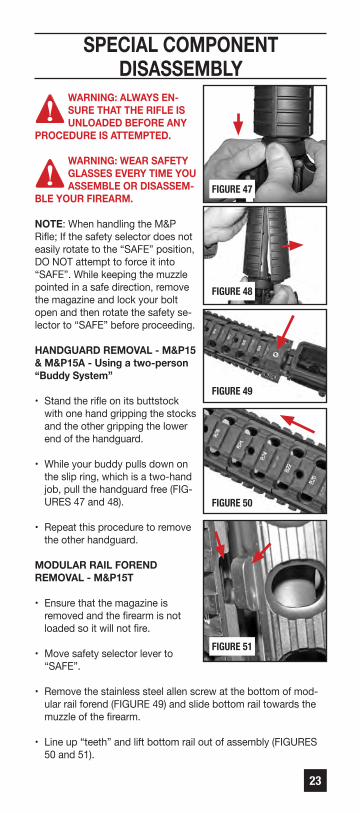
HANDGUARD REMOvAL - M&P15 & M&P15A - Using a two-person “Buddy System”
• Stand the rifle on its buttstock with one hand gripping the stocks and the other gripping the lower end of the handguard.
• While your buddy pulls down on the slip ring, which is a two-hand job, pull the handguard free (FIG-URES 47 and 48).
• Repeat this procedure to remove the other handguard.
MODULAR RAIL FOREND REMOvAL - M&P15T
• Ensure that the magazine is removed and the firearm is not loaded so it will not fire.
• Move safety selector lever to “SAFE”.
• Remove the stainless steel allen screw at the bottom of mod-ular rail forend (FIGURE 49) and slide bottom rail towards the muzzle of the firearm.
• Line up “teeth” and lift bottom rail out of assembly (FIGURES 50 and 51).
FIGURE 49
FIGURE 47
FIGURE 48
FIGURE 50
FIGURE 51

24
SPECIAL COMPONENT DISASSEMBLY CONT’DvIKING TACTICS & TROY HAND-GUARD REMOvAL - M&P15 vTAC® II & M&P15 TS Models -
• Loosen the 3 hex head screws using a No.10 (5/32˝) Allen wrench (FIGURES 52 thru 54). It is not necessary to completely remove the screws.
• Rotate the handguard to the left so the alignment tab on the forend is about 1/4˝ away from the receiver (FIGURE 55).
• Slide the forend forward (towards the muzzle) and off the barrel (FIGURE 56).
• Be careful not to damage the gas tube (FIGURE 58). No further dis-assembly is needed for cleaning.
• Re-assemble the handguard onto the rifle in the reverse order of the steps above. Keeping in mind that as you slide the forend against the receiver, the alignment tab on the forend should start about 1/4˝ to the left of the receiver and then be turned to the right so the tab is touching the receiver (FIG. 55).
• If the forend keepers get de-tached, install them as shown (FIGURES 57 and 59).
FIGURE 54
FIGURE 57FIGURE 56
FIGURE 59
Smoothsurfacestowardbarrel
nut
Gas tube
BArrel nut
Raised LugEngagesGroove in
Handguard
Gas tube
Barrel
BarrelNutFIGURE 58
FIGURE 52
FIGURE 53
FIGURE 55
25
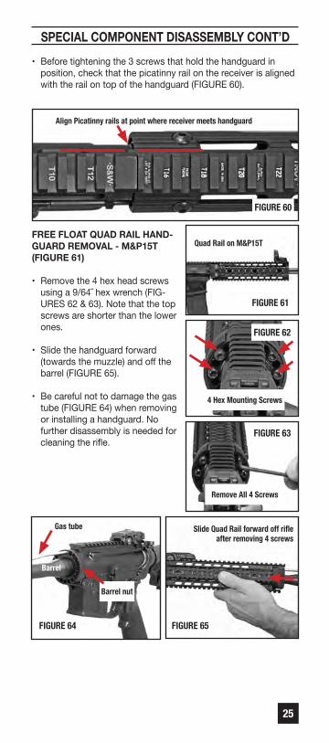
SPECIAL COMPONENT DISASSEMBLY CONT’D• Before tightening the 3 screws that hold the handguard in
position, check that the picatinny rail on the receiver is aligned with the rail on top of the handguard (FIGURE 60).
FREE FLOAT qUAD RAIL HAND-GUARD REMOvAL - M&P15T (FIGURE 61)
• Remove the 4 hex head screws using a 9/64˝ hex wrench (FIG-URES 62 & 63). Note that the top screws are shorter than the lower ones.
• Slide the handguard forward (towards the muzzle) and off the barrel (FIGURE 65).
• Be careful not to damage the gas tube (FIGURE 64) when removing or installing a handguard. No further disassembly is needed for cleaning the rifle.
FIGURE 62
FIGURE 65FIGURE 64
Quad Rail on M&P15T
4 Hex Mounting Screws
Remove All 4 Screws
Gas tube
Barrel nut
Barrel
Slide Quad Rail forward off rifleafter removing 4 screws
Align Picatinny rails at point where receiver meets handguard
FIGURE 60
FIGURE 61
FIGURE 63

26
SPECIAL COMPONENT DISASSEMBLY CONT’D• Re-assemble the handguard
onto the rifle in the reverse order of the steps above.
• The screws will only engage the handguard holes in the spots where there are threaded holes (FIGURE 66).
• Slide the handguard snug against the barrel nut and install the 4 screws (FIGURE 67). The short screws go in the top holes and the long screws go in the lower holes.
NOTE: The Quad Rail handguard has numbers preceded by a “T” on the top rail (FIGURE 68).
• Snug the 4 screws (FIGURE 69) that hold the handguard in position, check that the forend is aligned correctly with the receiver and barrel, then proceed to tight-en the screws uniformly
(FIGURE 70).
M-LOK® HANDGUARD RE-MOvAL from M&P15 Models so-equipped.
• Remove the M-LOK® hand-guard (FIGURE 71) by holding the slip ring down firmly and tipping the top and bottom halves of the handguard off the rifle. This works best with two people - one to hold the rifle and slip ring - one to pull the handguards off.
FIGURE 68
FIGURE 70FIGURE 69
FIGURE 71
FIGURE 66
FIGURE 67
View fromrear of
Quad Railshowing
screwholes
(circledhere in red)
and thenon-removable alignment pins
Quad Rail Aligned
Top has “T” Numbers
Tighten 2 Screws on each sideLong screws go inlower holes
Short screws go inupper holes

27
SPECIAL COMPONENT DISASSEMBLY CONT’DMAGPUL® MOE® MID-LENGTH HANDGUARD REMOvAL from M&P15 Models so-equipped.
• Stand the rifle on its buttstock in a location where two people have access to the unloaded rifle. FIGURE 72 shows the hand-guard in its correctly installed orientation.
• While the first person pulls down on the slip ring with two hands, the second person can pull the bottom half of the handguard free - out at the bottom and down out of the handguard cap. After the bottom half is removed - the first person pulls down on the slip ring and the top half is then removed (FIGURES 73 and 74).
• Re-install the top half of the handguard first and the bottom half second - as one person pulls down on the slip ring (FIGURES 75 and 76).
FIGURE 76FIGURE 75
FIGURE 74
FIGURE 72
FIGURE 73
AssembledMAGPUL®
MOE®mid-lengthhandguardshowingcorrect
orientation onM&P®15 rifle
Tire de lamitad superiordel guardam
anos pararetirarla
One personholds slipring down
One person holds slip ring down
Clip end ofhandguard
underretainer cap
Tip bottomhalf of
handguardinto place
One personholds slipring down
Clip end ofhandguard
underretainer cap
Tip top halfof handguard
intoplace
One personholds slipring
down
Pull bottomhalf off
handguardoff

28
SPECIAL COMPONENT DISASSEMBLY CONT’DHANDGUARD REMOvAL from M&P®15 “X” Models so-equipped.
• Remove the four (4) screws that secure the handguard halves together (FIGURE 77) with a 5/64˝ allen wrench.
• Stand the rifle on its butt-stock in a location where two people have access to the unloaded rifle.
FIGURE 78 shows the handguard in its correctly installed orientation.
• Using the “buddy system” - while the first person pulls down on the slip ring with two hands, the second person can pull the halves of the handguard free - tipping them out at the bottom first and then down out of the handguard cap at top (FIG-URE 80).
• Re-install the two halves of the handguard by first clip-ping them in the bracket at top and then bringing them together at the bottom - as one person pulls down on the slip ring with two hands.
• Re-install the (4) screws that secure the handguard halves together.
FIGURE 78
FIGURE 77
FIGURE 80FIGURE 79
Numbers visibleon top wheninstalled
This endtowardmuzzle
Pull bothhalves of
handguardoff at the
same timeas shown
Assembledhandguardshowingcorrectorientation onM&P15 “X” rifle
This endtowardreceiver
One personholds slipring down
Remove 4screws toseparate
handguardhalves
Re-install the 4 screwsafter installing
handguard on rifle

29
SPECIAL COMPONENT DISASSEMBLY CONT’DNOTE: A tool is available from Wheeler Engineering that makes it easy for one person to compress the slip ring for those hand-guards that are held in place by a slip ring. AR-15 DELTA RING TOOL - part #209943 at www.BTIbrands.com.
BOLT FIELD STRIPPING
• Tip upper receiver open as instructed previously (FIG.81).
• Pull back on the charging handle and bolt assembly (FIG. 82).
• Remove the bolt carrier assembly from the upper receiver.
• Pull the charging handle back and down to remove it from the upper receiver.
• Once the bolt carrier is clear of the firearm, move the bolt forward in the carrier to the unlocked position (FIGURE 83) and remove the firing pin retaining pin. Do not alter the split end of the firing pin retaining pin (FIGURE 84).
• Push the bolt into the bolt carrier to put it in the locked position (FIGURE 85).
• Remove the firing pin out of the rear of the bolt carrier (FIGURE 86).
NOTE: See section in this manual for details regarding the pistondriven variation and its unique instructions.
FIGURE 85
FIGURE 83
FIGURE 81
FIGURE 86
FIGURE 84
FIGURE 82

30
SPECIAL COMPONENT DISASSEMBLY CONT’D• Give the bolt cam pin a 1/4
turn and lift it out (FIGURE 87).
• Remove the bolt from the bolt carrier (FIGURE 88).
WARNING: DO NOT DISASSEMBLE THE EXTRACTOR OR THE
SPRING ASSEMBLY.
• Press the rear of the extractor to check that the spring works. (FIGURE 89) If there is no tension, you must take the extractor apart and clean the parts.
• Use a drift/pen tip to remove the extractor pin.
• Remove the extractor from the bolt. Do not remove the rubber grommet from the spring. (FIGURE 90)
BUFFER AND SPRING FIELD STRIPPING
• Push in buffer (at the rear of the receiver / front of the stock) slightly and depress buffer retainer to release the buffer (FIGURE 91).
• Remove buffer and spring from the buffer tube (FIG-URE 92).
WARNING: DO NOT ALTER, MODIFY OR REPLACE ANY OF THE PARTS OF YOUR FIREARM UNLESS THIS WORK IS PERFORMED BY A qUALIFIED GUN-
SMITH USING GENUINE SMITH & WESSON PARTS. IF YOU DO OTHERWISE, IMPROPER FUNCTIONING MAY OCCUR AND SERIOUS INJURY MAY RESULT.
WARNING: NEvER DISASSEMBLE YOUR FIREARM BEYOND THE FIELD STRIPPING PROCESS OUTLINED IN THIS MANUAL. NEvER MANIPULATE ANY INTERNAL
COMPONENTS BEYOND WHAT YOU ARE SPECIFICALLY IN-STRUCTED TO DO IN THIS MANUAL SINCE THIS MAY AFFECT THE RELIABILITY, FUNCTIONING AND SAFETY OF YOUR FIREARM.
FIGURE 89
FIGURE 92
FIGURE 88
FIGURE 91
FIGURE 87
FIGURE 90 EXTRACTOR PIN
SPRING

31
ASSEMBLYWARNING: ALWAYS FOLLOW THE FIELD STRIPPING IN-STRUCTIONS EXACTLY. NEvER DO ANYTHING BEYOND WHAT YOU ARE SPECIFICALLY INSTRUCTED TO DO
IN THIS MANUAL. NEvER ALTER OR MODIFY THE PARTS IN YOUR FIREARM.
WARNING: WEAR SAFETY GLASSES EvERY TIME YOU ASSEMBLE OR DISASSEMBLE YOUR FIREARM.
• Assemble your rifle in the reverse order that you took it apart.
• Make sure that the gas-rings on the bolt are not aligned when reassem-bling. (FIGURES 93 and 94)
• Lubricate all metal parts by wiping them with a cloth dampened with a high quality firearm oil. Remove excess oil. Leave a light film of oil on all metal parts of your rifle - inside and out.
NOTE: See the section in this manual for details regarding thepiston driven variation and its unique instructions.
CARRY HANDLE - WHEN SO-EqUIPPED
WARNING: ALWAYS ENSURE THAT THE RIFLE IS UN-LOADED BEFORE ANY PROCEDURE IS ATTEMPTED.
FOR OPTICS INSTALLATION
• Loosen both screws on the side of the carry handle (FIG. 95).
• Lift carry handle up and off receiver.
FIGURE 95
FIGURE 94
FIGURE 93
Incorrect Alignment
Correct Alignment

32
COLLAPSIBLE STOCK WHEN SO-EqUIPPED
• To extend the collaps-ible stock, depress lever (FIGURE 96) and pull the stock out until it locks into position.
• To collapse the buttstock, depress the lever again and push forward until it locks into position.
SIGHT ADJUSTMENT WHEN SO-EqUIPPED
WARNING: ALWAYS ENSURE THAT THE RIFLE IS UN-LOADED BEFORE ANY PROCEDURE IS ATTEMPTED.
DUAL APERTURE REAR SIGHT
• This sight has a dual aperture (FIGURES 97 and 98). Use the larger aperture for normal range firing. Use the small aperture for longer range firing.
NOTE: Raise the rear sight up to raise the bullet’s point of im pact on target and move it down to low er the bullet’s point of impact on target. Follow the UP and DN arrows to adjust your bullet’s striking point on target.
• Turning the windage ad-justment clockwise moves your group to the right ( “R” Right arrow is stamped into the sight knob). Turn-ing the wind age screw counter-clockwise moves the point of impact to the left (FIGURE 99).
FIGURE 96
FIGURE 99
FIGURE 98
FIGURE 97

33
SIGHT ADJUSTMENT CONTINUEDREAR BATTLE SIGHT - (If so-equipped) (FIGURE 100)
• This sight has a dual aperture. Use the larger aperture for normal range firing. Use the small aper-ture for longer range firing. Windage adjustments can be made with the rear sight. Adjustments can be made by turning the windage adjustment wheel with a small punch or pen tip.
NOTE: Be sure that the large rear sight aperture is deployed before folding the rear battle sight.
FRONT BATTLE SIGHT (If so-equipped) (FIGURE 101)
• If elevation adjustment beyond what the rear sight alone provides is needed, the front sight post can be moved up or down. (FIG-URE 101) Depress the front sight detent and rotate the post counterclockwise to raise the post and lower the shot’s impact - and clockwise to lower the post and raise the shot’s point of impact
NOTE: Raise the front sight post up to lower the shot’s point ofimpact and down to raise the shot’s point of impact.
TO RAISE YOUR BATTLE SIGHT (If so-equipped)• Lift up on the sights until they lock into position.
TO LOWER YOUR BATTLE SIGHT (If so-equipped)• Depress the stud on the left side of the sight base while folding
the sights rearward.
ADJUSTABLE FRONT SIGHT POST (If so-equipped)
• If elevation adjustment beyond what the rear sight alone pro-vides is needed, the front sight post can be moved up or down. (FIGURE 102) Depress the front sight detent and rotate the post counterclockwise to raise the post and lower the shot’s impact - and clockwise to lower the post and raise the shot’s point of impact.
FIGURE 100
FIGURE 102
FIGURE 101DepressDetentto AllowPost toturn

34
SIGHT ADJUSTMENT CONTINUEDMAGPUL® MBUS® FOLDING REAR SIGHT - (If so-equipped)
• The Magpul® MBUS® spring-loaded, folding rear sight (FIGURE 103) is a dual aperture rear sight that is adjustable for wind-age (FIGURE 104). Turn the knob right to change the bullet impact to the right. The sight flips up by press-ing the tab from either side or by pressing the central area on top (FIGURE 103). The sight can be folded with either large or small aperture in position.
DUAL APERTURE REAR SIGHT
• The Magpul® MBUS® rear sight has a dual aper-ture that is deployed by flipping the smaller opening aperture up into position (FIGURE 105) - or forward (down) to use the large opening. Use the larger aperture for normal range firing. Use the small aperture for longer range precision firing (FIGURES 106 and 107).
MAGPUL® MBUS® FOLDING FRONT SIGHT - (If so-equipped)
• The Magpul® MBUS® spring-loaded, folding front sight (FIGURE 108) is adjustable for elevation. It flips up by pressing the tab from either side or by pressing the central area on top. An elevation adjustment tool is included. Use the tool to turn the sight post (clockwise as viewed from top) down to raise the impact of the bullets’ on target and counter-clockwise (up) to lower the bullets’ impact on target (FIGURE 108).
FIGURE 108
FIGURE 107
FIGURE 106
FIGURE 105
FIGURE 104
FIGURE 103
WINDAGEADJUSTMENT
Smallaperturetippeddown
Smallaperturetippedup intoposition
Elevation adjustment

35
INSTALLATION OF OPTICSWARNING: ALWAYS ENSURE THAT THE FIREARM IS UNLOADED BEFORE INSTALLING A SCOPE, OPTICAL SIGHT OR ANY OTHER ACCESSORIES. FAILURE TO DO
THIS CAN RESULT IN INJURY OR DEATH TO YOU OR OTHERS AND DAMAGE TO PROPERTY.
• We recommend that you have a competent gunsmith install your scope and mount.
• Scopes and optical sights have varying lengths of recommend-ed eye relief. You need to choose a combination that allows for adequate clearance between the scope and your eye brow. Follow the instructions supplied with the scope and rings for proper installation.
WARNING: FIRING A FIREARM WITH YOUR EYE TOO CLOSE TO THE EYE PIECE OF A SCOPE OR OPTICAL SIGHT, OR FAILING TO HOLD THE FIREARM SECURELY
AGAINST RECOIL, MAY RESULT IN SERIOUS PERSONAL INJU-RY INCLUDING, BUT NOT LIMITED TO, BLINDNESS.
WARNING: A SCOPE OR OPTICAL SIGHT WHICH IS NOT SECURELY MOUNTED MAY BECOME DETACHED UPON RECOIL OF THE FIREARM. IF IT BECOMES DETACHED
IT MAY FLY BACK AND STRIKE THE SHOOTER OR A BYSTAND-ER AND CAUSE INJURY. OBSERvE THE CONDITION OF ALL THE SCOPE MOUNT SCREWS AFTER FIRING. IF THE MOUNT-ING SCREWS SHOW SIGNS OF LOOSENING DO NOT FIRE THE GUN AGAIN; CALL THE CUSTOMER SERvICE DEPT. FOR ASSISTANCE AT 1-800-331-0852 EXT 4125.

36
MAGAZINEWARNING: WEAR SAFETY GLASSES EvERY TIME YOU ASSEMBLE OR DISASSEMBLE YOUR MAGAZINE.
• FIGURE 109 shows the parts that make up the magazine.
MAGAZINE DISASSEMBLY
• Using a small. blunt object (such as an allen wrench), push the floorplate retainer down by passing the tool through the hole in the floorplate (FIGURE 110).
• While holding the retainer down - slide floorplate forward off of the tube while keeping your finger over the tube to prevent the spring from flying out (FIGURES 110 and 111).
WARNING: MAG-AZINE SPRING IS UNDER PRESSURE.
CONTROL THE SPRING AND THE FLOOR PLATE RETAINER SO THAT THEY DO NOT FLY OUT AND CAUSE INJURY.
• Remove floorplate, the spring and the follower out through bottom of the magazine tube.
MAGAZINE REASSEMBLY
• Install the follower and spring into the magazine tube.
• While holding the spring down (under tension) in the tube, slide the floorplate onto the magazine tube (over the tabs) until the floorplate locks it into place.
FIGURE 112
FIGURE 111
FIGURE 110
FIGURE 109Floor plate
Tube
Follower Spring Floor plateretainer
Image showing dust coverin place on magazine

37
PISTON OPERATED vARIATION WHEN SO-EqUIPPED
WARNING: ENSURE THAT YOUR FIREARM IS UNLOAD-ED BEFORE BEGINNING TO CLEAN IT. (SEE “INSPECT-ING YOUR FIREARM” SECTION). ALWAYS FOLLOW THE
RULES OF SAFE FIREARM HANDLING.
WARNING: WEAR SAFETY GLASSES THAT ARE SPECI-FIED FOR FIREARMS USE EvERY TIME YOU ASSEMBLE OR DISASSEMBLE YOUR FIREARM.
• This section details important information regarding the disas-sembly, assembly and operation of the piston driven variation of the M&P®15 centerfire rifle. Read and understand all previ-ous sections of this manual regarding safety and operation of the M&P®15 rifle.
• You can identify this variation of the M&P®15 by the presence of a knurled selector knob on the gas transfer block at the end of the forend (FIGURE A1).
• The gas transfer block on the barrel incorporates an adjustable gas interface (FIGURE A2). The locking detent is spring loaded to allow several positions to be selected.
• As viewed from the muzzle end; when the spring load-ed plunger is in the detent straight up (12 o’clock) it is in Normal Mode (FIGURE A3). The Normal Mode position allows for optimal gas passage into the gas plug/operating rod and is appropriate for regular semi-automatic fire.
• When the spring loaded plunger is in the one o’clock position it is in Reduced Gas Port Mode (FIGURE A4). The Reduced Gas Port Mode position reduces the amount of gas passing into the operating system by approximately 60%.
FIGURE A1
FIGURE A2
FIGURE A3
FIGURE A4

38
PISTON OPERATED MODEL CONTINUED• When the spring loaded
plunger is in the three o’clock position it is in Single Shot Mode (FIGURE A5). The Single Shot Mode position eliminates the passage of gas through the gas plug. Accordingly, when firing in this mode, the operating rod will not get pushed back and the bolt will not cycle after a cartridge is fired. The operator will have to manu-ally cycle the bolt to extract the cartridge casing and chamber another round.
• When the spring loaded plunger is in nine o’clock position it is in the Takedown (removal) position (FIGURE A6).
WARNING: NEvER ATTEMPT TO FIRE THE RIFLE WITH THE GAS PORT SELECTOR IN THE TAKEDOWN POSITION OR WITH THE OPERATING ROD (PISTON)
REMOvED. SERIOUS INJURY AND DAMAGE TO PROPERTY MAY RESULT.
• With the spring loaded plunger in the nine o’clock position, the gas piston and operation rod can be removed from the rifle for cleaning or maintenance (FIGURES A7 & A8).
FIGURE A8
FIGURE A7
FIGURE A6
FIGURE A5
The parts are not fastened together - becertain that you withdraw all parts shown in FIGURE A9 when you remove the piston assembly.

39
PISTON OPERATED MODEL CONTINUED• The gas piston/operating rod assembly is made up of 4 parts
(FIGURE A9). After cleaning these parts, lubricate them lightly to prevent rust and corrosion, reassemble the parts as shown (FIGURE A10) and re-install in rifle.
BOLT FIELD STRIPPING
• Tip upper receiver open as instructed previously (FIGURE A11).
• Pull back on the charging handle and bolt assembly (FIGURE A12).
• Remove the bolt carrier assembly from the upper receiver (FIGURE A13).
• Pull the charging handle rearward and then down
to remove it.
• Once the bolt carrier is clear of the firearm, remove the firing pin retaining pin. Do not alter the split end of the firing pin retaining pin (FIGURE A14).
FIGURE A9
FIGURE A10
FIGURE A11
FIGURE A12
FIGURE A13
FIGURE A14
The “cupped” side of thespring guide goes against thespring when reassembling
This photo shows the parts inproper position for reas-sembly.

40
PISTON OPERATED MODEL CONTINUED• Push the bolt into the
bolt carrier to put it in the locked position (FIGURE A15).
• Remove the firing pin out of the rear of the bolt carri-er (FIGURE A16).
• Give the bolt cam pin a 1/4 turn and lift it out (FIG. A17).
• Remove the bolt from the bolt carrier (FIGURE A18).
• FIGURE A19 shows the extent to which the bolt and bolt carrier should be disassembled for cleaning.
• For reassembly, be sure to properly place the spring on the bolt (FIGURE A20) before sliding the bolt back into the bolt carrier.
FIGURE A20
FIGURE A19
FIGURE A18
FIGURE A16
FIGURE A15
FIGURE A17
This photo shows the bolt and bolt spring in the proper position for reassembly.
41
BULLET BUTTON® vARIATION WHEN SO-EqUIPPED
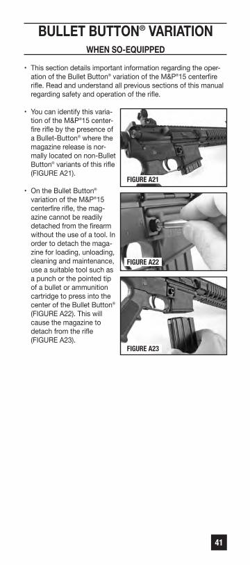
• This section details important information regarding the oper-ation of the Bullet Button® variation of the M&P®15 centerfire rifle. Read and understand all previous sections of this manual regarding safety and operation of the rifle.
• You can identify this varia-tion of the M&P®15 center-fire rifle by the presence of a Bullet-Button® where the magazine release is nor-mally located on non-Bullet Button® variants of this rifle (FIGURE A21).
• On the Bullet Button® variation of the M&P®15 centerfire rifle, the mag-azine cannot be readily detached from the firearm without the use of a tool. In order to detach the maga-zine for loading, unloading, cleaning and maintenance, use a suitable tool such as a punch or the pointed tip of a bullet or ammunition cartridge to press into the center of the Bullet Button® (FIGURE A22). This will cause the magazine to
detach from the rifle (FIGURE A23).
FIGURE A23
FIGURE A22
FIGURE A21

42
CLEANING AND MAINTENANCEWARNING: ENSURE THAT YOUR FIREARM IS UNLOAD-ED BEFORE BEGINNING TO CLEAN IT. (SEE “INSPECT-ING YOUR FIREARM” SECTION). ALWAYS FOLLOW THE
RULES OF SAFE FIREARM HANDLING.
WARNING: WEAR SAFETY GLASSES EvERY TIME YOU ASSEMBLE OR DISASSEMBLE YOUR FIREARM AND ATTEMPT CLEANING OR MAINTENANCE.
• Before using your firearm for the first time, it should be cleaned.
• Your firearm was treated at the factory with either a preserva-tive or oil to protect it against corrosion during shipping and storage.
• Preservative and oil should be wiped from the bore, chamber and exposed areas using a clean swab or patch before using the firearm.
CAUTION: Never disassemble your firearm beyond the in-structions in the Field Stripping and Inspection sections of this manual.
• Purchase cleaning supplies from your firearms dealer that are specifically designated for your type and caliber of firearm. Many suppliers offer these in kit form for your convenience.
• Follow the instructions provided with your cleaning supplies.
NOTE: A basic firearm cleaning kit should include: a brass borebrush and a cleaning jag of appropriate size for the bore beingcleaned, high-quality gun cleaning solvent and gun oil/lubricant,cotton cleaning patches and a cleaning rod that is long enoughto push the brush and jag completely through the barrel.
• Remove excessive firing residue from the bore and chamber using a properly fitted brass brush dipped in gun cleaning sol-vent. Finish the bore cleaning process by running a dry cotton cloth patch through the bore and chamber to remove residue and solvent.
• Clean the exterior of the firearm using a non-abrasive cleaning cloth.
• After cleaning, lightly coat the metal parts, internal and external with a high quality firearm oil.
• Whenever your firearm has been exposed to sand, dust, extreme humidity, water or other adverse conditions, it must be cleaned and lubricated.

43
CLEANING AND MAINTENANCE CONTINUEDWARNING: ALWAYS HAvE ADEqUATE vENTILATION. CLEANING FIREARMS IN POORLY vENTILATED AREAS, DISCHARGING FIREARMS, OR HANDLING AMMUNI-
TION MAY RESULT IN EXPOSURE TO LEAD AND OTHER SUB-STANCES KNOWN TO CAUSE BIRTH DEFECTS, REPRODUC-TIvE HARM AND OTHER SERIOUS PHYSICAL INJURY. WASH HANDS THOROUGHLY AFTER EXPOSURE.
CAUTION: Always follow the instructions provided with your firearm cleaner and firearm lubricant.
CAUTION: The gas tube will discolor from heat. Do not attempt to remove the discoloration.
CAUTION: Some cleaners can cause damage to your firearm. You should avoid prolonged solvent immersion and prolonged ultrasonic cleaning of your firearm. Choice of solvent should be restricted to those products specifically developed for firearms maintenance. Damage to a firearm’s finish may occur if these cautions are ignored. Ammoniated solvents or other strong alkaline solvents, should not be used on any Smith & Wesson firearm. Cleaning is essential to ensure the proper functioning of your firearm.
• Your firearm is a precision instrument. To ensure reliable func-tion it is necessary to follow a routine maintenance procedure. After firing your firearm, be sure to unload it following the procedure outlined in the section entitled “Inspecting Your Firearm” before performing any cleaning or maintenance pro-cedure.
• Remove any firearm cleaning solution, oil and fingerprints from the outside surfaces of the firearm. (Finger moisture, if left, could start a corrosion process).
WARNING: NEvER MANIPULATE, ADJUST OR CHANGEANY OF THE INTERNAL COMPONENTS OF YOURFIREARM UNLESS SPECIFICALLY DIRECTED TO DO
SO IN THIS MANUAL. IMPROPER MANIPULATION OF ANY INTERNAL COMPONENT MAY AFFECT THE SAFETY AND RELIABILITY OF YOUR FIREARM AND MAY CAUSE SERIOUS INJURY OR DEATH.
WARNING: ANY MAINTENANCE, ADJUSTMENT OR SERvICE NOT SPECIFIED IN THIS MANUAL MAY AFFECT THE SAFETY AND RELIABILITY OF YOUR FIRE-
ARM AND MUST BE PERFORMED BY A qUALIFIED GUNSMITH USING GENUINE SMITH & WESSON PARTS. IF YOU DO OTH-ERWISE, IMPROPER FUNCTIONING OF YOUR FIREARM MAY OCCUR AND SERIOUS INJURY OR DEATH MAY RESULT.
• If your firearm will be used in a cold climate, be sure to use an oil of an appropriate weight so that it will not congeal in cold temperatures, causing the interaction of important parts to be slowed or halted.

44
CLEANING AND MAINTENANCE CONTINUEDMAINTENANCE BEFORE STORAGE
• When storing, do not encase your firearm in anything that will attract or hold moisture, for example, leather or heavy cloth. Also, do not store firearms with a plug inserted in the barrel for this can be a contributing factor to moisture accumulation. If your firearm is to be stored for an extended period, the bore, chamber and internal surfaces should be oiled with a high quality lubricating oil or preservative intended for firearms.
• The external parts; receiver, bolt and barrel should be coated with an anti-rust oil. Before using your firearm again, be sure to clean it. Every time you clean your firearm, check it for signs of wear. If wear is noted, do not use the firearm. Return it to Smith & Wesson for service or have it checked by a qualified gunsmith.
CAUTION: Use of ammunition manufactured with corrosive prim-ers in this firearm will cause oxidation to develop on any exposed metal parts of the firearm. To prevent such oxidation, the residue from corrosive primers must be completely removed from all exposed metal parts after each time ammunition with corrosive primers is used in this firearm. Conventional oil or solvent-based firearm cleaners WILL NOT dissolve the residue from corrosive primers. Residue from corrosive primers MUST be completely dissolved with a water-based cleaner. After the corrosive residue has been completely dissolved from all exposed metal parts, remove any excess water-based cleaner from the firearm. Finally, lubricate the firearm as instructed in the Safety and Instruction Manual. Failure to follow these instructions will cause damage to the firearm and may affect the ability of the firearm to function properly.
Check with the ammunition manufacturer or a qualified gunsmithif you are unsure whether the particular ammunition you plan touse in this firearm has been manufactured with corrosiveprimers. If in doubt, follow all the instructions above to preventoxidation caused by ammunition manufactured with corrosiveprimers.
Ammunition manufactured by SAAMI member companies do notuse corrosive primers.

45
LIMITED WARRANTY For Owners Within The United States.
This warranty is granted by Smith & Wesson Inc. This warrantyis effective from the date of purchase and applies to the originalowner of any firearm. With respect to such firearms, this warrantysupersedes any and all other warranties.
Smith & Wesson® firearms are warranted to be free from defectsin material and workmanship. Any such defects of which Smith& Wesson receives written notice within one year from the dateof purchase by the original owner, will be remedied by Smith &Wesson without charge within a reasonable time after such notifi-cation and delivery of the firearm as provided below.
In the event of an emergency (repairs needed by law enforce-ment, an upcoming match or hunting trip), call 1-800-331-0852,ext. 4125 and ask for 911 Priority Repair Service. This allowsyou to speak with a Smith & Wesson representative. Immediatelyupon receipt, your firearm will be assigned to a gunsmith. Afterthe work is completed, we will return your Smith & Wessonfirearm via overnight delivery.
Warranty claims (in writing) and the firearm concerned should bedelivered to Smith & Wesson’s Customer Service Department,2100 Roosevelt Avenue, Springfield, Massachusetts 01104. Inaddition, a copy of the bill of sale in the owner’s name, or acopy of ATF Form 4473 indicating date of purchase must beincluded. It is important that the owner comply with all applicablefederal, state and local laws and regulations in the shipmentof firearms to Smith & Wesson.
NOTE: See the Contact & Shipping section of this manual forfurther details regarding returns.
Warranty claims should state the model and serial number of thefirearm concerned and the description of the difficulty experi-enced. It is recommended that shipments be insured by theowner, since Smith & Wesson will accept no responsibility forloss or damage in transit. Transportation and insurance chargesfor return to owner will be paid by Smith & Wesson if the claim iscovered by the warranty.
UNDER NO CIRCUMSTANCES SHALL SMITH & WESSON BERESPONSIBLE FOR INCIDENTAL OR CONSEqUENTIAL DAMAGES WITH RESPECT TO ECONOMIC LOSS, INJURY, DEATH OR PROPERTY DAMAGE, WHETHER AS A RESULT OF BREACH OF THIS WARRANTY, NEGLIGENCE OR OTH-ERWISE.
Some states do not allow the exclusion or limitation of incidentalor consequential damages, so the above limitation or exclusionmay not apply to you.

46
LIMITED WARRANTY CONTINUEDSmith & Wesson will not be responsible for:
• Defects or malfunctions resulting from careless handling, unauthorized adjustments or modifications made or attempted by anyone other than a qualified gunsmith following Smith & Wesson® authorized procedures, or failure to follow the disas-sembly instructions in the Smith & Wesson manual.
• Use of defective or improper ammunition, corrosion, neglect, abuse, ordinary wear and tear, or unreasonable use.
• Criminal misuse, negligence or use under the influence of drugs or alcohol.
Smith & Wesson’s Lifetime Service Policy begins after the war-ranty period has expired. Smith & Wesson will repair, withoutcharge, for the lifetime of the original owner, any Smith &Wesson® handgun purchased on or after February 1, 1989, andany M&P® series rifles, that is found to have a defect in materialor workmanship. Eligibility for this Lifetime Service Policyrequires returning the Product Registration Card within 30 daysof purchase. The Lifetime Service Policy covers functionaldefects; it does not include the firearm’s finish, grips, magazinesor sights. The Lifetime Service Policy is in addition to and not anextension of the Smith & Wesson Warranty.
This warranty gives you specific legal rights. You may also haveother rights that vary from state to state.
NOTE: All liability is excluded in the event that the instructionsin the Smith & Wesson manual are not observed.

47
CONTACT AND SHIPPING INFORMATION
For Owners Within The United StatesNOTE: A Return Merchandise Authorization (RMA) is the firststep in the process of returning a product in order to receive arepair, replacement or refund. Please contact Smith & Wesson’sCustomer Service Dept. (via e-mail: [email protected] orby phone at 1-800-331-0852 ext. 4125) to obtain authorization toreturn your firearm so we can process it quickly and efficiently.The RMA number that is supplied by Smith & Wesson must bedisplayed on the outside of the returned product’s packaging;returns without an RMA number will be routed differently whichwill result in delayed processing.
The issuance of an Return Merchandise Authorization (RMA)allows Smith & Wesson an opportunity to try to diagnose andcorrect a customer’s concerns with the product (such as ammu-nition problems) before it is returned. Accordingly, please contactus before returning your Smith & Wesson firearm.
CONTACT CUSTOMER SERvICETel: 1-800-331-0852 • 1-413-781-8300 ext. 4125
E-mail: [email protected] - FOR SERVICE
ALL SMITH & WESSON FIREARMSSmith & Wesson
2100 Roosevelt AvenueSpringfield, MA 01104
Should your Smith & Wesson firearm require service, it should be returned to the Smith & Wesson factory.
• Call or e-mail the Customer Service Dept. for authorization and shipping instructions.
• Ensure that the firearm is unloaded.
• Do not attempt to ship a firearm via US Postal Service; only federally licensed dealers may ship a firearm by US Postal Service.
• DO NOT SHIP ANY AMMUNITION.

48
CONTACT AND SHIPPING CONTINUED• Enclose a letter which includes your full name and address
(no P.O. Boxes, please), daytime telephone number, e-mail address, the serial number of the firearm, and details of the problem experienced (stating the brand and type of ammuni-tion used when the problem occurred) or work desired.
• Record the serial number before shipping, in case you wish to check on the repair status of your firearm.
• Please remove all custom parts and accessories, such as stocks, special sights and scopes, or slings from your firearm before returning.
• Place the firearm in its original case or in a similarly secure container and pack it securely.
• The package must NOT bear any markings which indicate the identity of the contents.
• It is most important that you comply with federal, state, and local laws and regulations. The following guidelines are meant to help, but you must seek assistance from the appropriate authorities if necessary.
• If your firearm must be replaced, it may be necessary to ship the replacement to a dealer rather than directly to you. You will be requested to furnish a signed FFL (Federal Firearms License) from your dealer in such an instance.
• Warranty repair work will begin upon receipt and examination of the firearm. In the case of repairs or work not covered by the warranty, a quotation covering the cost of the work plus round trip transportation charges will be sent to you. Repairs or modi-fication will be scheduled upon receipt of payment.
• A parts list can be obtained by contacting Smith & Wesson
WARNING: YOU MAY PURCHASE ACCESSORIES FOR YOUR SMITH & WESSON FIREARM. YOU MUST HAvE SOME OF THESE PARTS INSTALLED BY A GUNSMITH
qUALIFIED TO PERFORM SERvICE ON SMITH & WESSON FIREARMS. YOU MUST NEvER ATTEMPT TO MODIFY YOUR FIREARM OR INSTALL REPLACEMENT PARTS IN YOUR FIRE-ARM. ALWAYS USE A qUALIFIED SMITH & WESSON GUN-SMITH EvEN IF THE REPAIR SEEMS TO BE SIMPLE.

49
CUSTOM SERvICEWe understand that Smith & Wesson gun owners may want toenhance their guns with custom gunsmithing, refinishing oraccessories. Our gunsmiths offer specialized services andexclusive products to enhance your shooting experience.
Accessories for your Smith & Wesson firearm are available fromyour local Smith & Wesson Stocking Dealer, or directly fromSmith & Wesson.
Contact the Customer Service Department at 1-800-331-0852,ext. 4125 for information about these services.
When ordering directly from the factory, please provide thefollowing information:
• Model Number• Dash Number• Serial Number• Approximate date of purchase• Complete Return Address• VISA/Discover/MasterCard Number & Expiration Date• For Foreign Orders Only, Fax Number or E-mail Address
PATENT INFORMATION• This product may be covered by one or more patents. Visit www.smith-wesson.com for virtual patent information.

50
ADDENDUM: M-LOK® ACCESSORY RAILS
WARNING: ALWAYS ENSURE THAT THE FIREARM ISUNLOADED BEFORE INSPECTING, DISASSEMBLING OR ASSEMBLING (INCLUDING ACCESSORIES) AND
ALWAYS KEEP THE MUZZLE POINTED IN A SAFE DIRECTION.
The MAGPUL® M-LOK® Accessory Rail System
• The versatility of the M-LOK® system lies in accommodating various thicknesses of mounting surfaces and the adjustments that allow this functionality, the tips below will help the user to have the best possible results in the fastest possible time.
• Your M-LOK® accessory may arrive with nuts and ny-lon-patched (thread lock material) screws installed or with the nuts and screws loose with the accessory you have purchased. If the screws are loose, simply thread the nuts onto the screws through the accessory rail as shown (FIGURE B3).
• The nylon patch may seem “stiff˝ for the first installation of the new screws into the T-Nuts. Use a 7mm wrench to hold the T-Nut and to thread it onto the screw, then backing it off to the appropriate clearance adjustment will “break in˝ the nylon patch, and subsequent use will be easy.
T-NUTS
SCREWS
RAIL
FIGURE B1
FIGURE B2
FIGURE B3
Look for the M-LOK® logo that designates
genuineM-LOK® system
components
M&P15 shownwith M-LOK®rails in place

51
M-LOK® ACCESSORY RAILS CONTINUED• The nylon patch on the screws actually aids function by provid-
ing friction to turn the nuts. If you remove and replace the accessory numerous times, the nylon patch may eventually wear. You also may receive an after-market accessory without the patch on the screws. If the nut is not turning appropriately, the patch effect may be restored with either Rocksett™ or Loctite™ blue thread-locker stick. If the screws come without the patch, one of the above products is recommended for best function and durability.
ADJUSTING THE NUT TO THE CORRECT HEIGHT
• For best function, the T-Nut “gap˝ must be slightly greater than the thickness of the mounting surface (see FIGURE B4). This can be done by measuring the mounting surface thickness directly or using the edge of the mounting surface as a gauge. For most aluminum mounting surfaces setting the nuts as depicted below, with the highest edge of the T-Nut even with the bottom edge of the recoil lug, will provide correct function. Some thicker rails or polymer rails may require the nuts to be looser with a one or two thread(s) gap between the nuts and recoil lugs.
• Some accessories may arrive preset to the condition shown in the illustration for easy installation on aluminum handguards. Remember to loosen the nuts a bit for installation on polymer handguards.
TOO MUCH GAP
TOO LITTLE GAP
PROPER GAP
CROSS-SECTION OF HAND-GUARD
T-NUTS ARE TOO LOOSE
T-NUTS ARE TOO TIGHT
T-NUTS ARE ADJUSTED TO PROPER GAP
CROSS-SECTION OF HAND-GUARD
CROSS-SECTION OF HAND-GUARD
PRIOR TO INSTALLATION
FIGURE B4

52
M-LOK® ACCESSORY RAILS CONTINUED• Apply some downward force on the hex wrench to make sure
that the screw is seated, and then tighten (FIGURE B5).
ENSURE THAT THE ACCESSORY IS FULLY SEATED INTO ASLOT AND TIGHTENED INTO POSITION WHEN MOUNTING
• The bottom of the accessory should sit flush with the mounting alignment surface. If it doesn’t then slide the accessory fore-aft until it drops fully into the slot with the lugs engaged (FIGURE B6).
• For maximum repeatability, “bias˝ the accessory before fully tightening. By bias we mean settle the accessory toward the front where recoil won’t give the accessory a “running start˝ to move when firing.
• To bias the accessory, apply just enough lateral pressure (down and forward) to the accessory to make solid contact with one side and the front (towards muzzle) of the slot, similar to when installing a Picatinny rail accessory. Then tighten all fasteners to the recommended torque spec. This step is not necessary, but aids repeatability.
WARNING: AN ACCESSORY WHICH IS NOT SECURELY MOUNTED MAY BECOME DETACHED UPON RECOIL OF THE FIREARM. IF IT BECOMES DETACHED IT MAY
FLY BACK AND STRIKE THE SHOOTER OR A BYSTANDER AND CAUSE INJURY. OBSERvE THE CONDITION OF ALL THE MOUNTING SCREWS AFTER FIRING. IF THE MOUNTING SCREWS SHOW SIGNS OF LOOSENING DO NOT FIRE THE FIREARM AGAIN; TAKE IT TO A qUALIFIED GUNSMITH FOR ASSISTANCE.
MAKE CERTAIN THAT YOURACCESSORY IS FULLY SEATED IN THE SLOTS AND TIGHTENED SECURELY.
FRONT OF FIREARMAND FORWARD
PUSHDOWN
T-NUT POSITION TOINSTALL/UNINSTALL
SLOT IN HAND GUARD
T-NUT ROTATES WHENYOU TIGHTEN IT
T-NUT IN LOCKEDPOSITION
SCREW IS TIGHT
MAKE CERTAIN THAT YOURACCESSORY IS FULLY SEATED IN THE SLOTS AND TIGHTENED SECURELY.
FRONT OF FIREARMAND FORWARD
PUSHDOWN
T-NUT POSITION TOINSTALL/UNINSTALL
SLOT IN HAND GUARD
T-NUT ROTATES WHENYOU TIGHTEN IT
T-NUT IN LOCKEDPOSITION
SCREW IS TIGHT
FIGURE B5
FIGURE B6

53
M-LOK® ACCESSORY RAILS CONTINUEDENSURE THAT THE NUT ROTATES THE FULL 90 DEGREES INTO THE LOCKED POSITION
• If you have adjusted the nuts appropriately, they should rotate into perfect 90 degree alignment with a 1/4 turn of the screw, once it is aligned, the screw draws the nut against the interior of the handguard (FIGURE B7).
IF THE T-NUTS ARE NOT ROTATING PROPERLY:
• When nuts are spaced too loosely (where they do not contact the interior handguard surface - then the nut will rotate freely without stopping and tightening. In this case the nut will have to be screwed in closer to the bottom of the accessory. Simply remove the accessory from the slot and screw the nut on one full turn. Repeat as necessary so that the cam engages the slot when the screw is tightened.
• If the nut is spaced too close to the accessory, then the “wings˝ of the nut will contact the sides of the slot and the nut will not rotate into place. This will cause the nut to tighten against the accessory lugs without engaging the handguard.
• In this case the nut should be unscrewed until it is spaced far enough away from the lugs to allow it to rotate properly into position. Unscrew the nut one turn at a time and retest func-tion.
NOTE: It is best to observe the T-Nut rotating into locked posi-tion, if possible, to be certain that it turns 90 degrees into place and stays there during tightening.
• Most handguards or other mounting surfaces have holes or vents that can be seen through to confirm that the M-LOK® T-Nuts are properly engaged with the slot, and are perpendicu-lar to the slot orientation.
1/8˝ Hex Wrench
Handguard Cutawayto show T-Nuts Engaged
FIGURE B7

54
M-LOK® ACCESSORY RAILS CONTINUED• If the nut won’t rotate, or it
rotates too freely to engage the handguard, you may need to hold or turn the nut with a 7mm open-end wrench (FIGURE B8).
• If it is not possible to watch the nut rotate, then careful attention needs to be paid to the screw as it is tightened. The screw should turn easily for the first quarter turn, then when the nut stops rotating it will become slightly more difficult to turn. Continue tightening until secure. Pull on both ends of the accessory to ensure it is engaged correctly.
THE M-LOK® SYSTEM TORqUE SPECS• For attaching polymer accessories to metal handguards: 15 in/lbs.
• For attaching polymer or metal accessories to polymer hand-guards: 15 in/lbs.
• For attaching metal accessories to metal handguards: 35 in/lbs.
• The installation torque values are not minimums, they are recommended limits. The nylon patch compound (thread lock) may slightly affect the torque reading if using an in/lb torque wrench.
• Using a small hex wrench should prevent over-tightening. Remember that the recoil lugs are doing most of the work, and excessive torque on the nuts is not required.
WARNING: APPLYING EXCESSIvE TORqUE TO THE ACCESSORY RAILS AND HANDGUARDS MAY CAUSE DAMAGE TO THEM RESULTING IN AN INSECURE
MOUNT. A RAIL OR ACCESSORY WHICH IS NOT SECURELY MOUNTED MAY BECOME DETACHED UPON RECOIL OF THE FIREARM. IF IT BECOMES DETACHED IT MAY FLY BACK AND STRIKE THE SHOOTER OR A BYSTANDER AND CAUSE INJURY. OBSERvE THE CONDITION OF ALL THE RAIL COMPONENTS BEFORE FIRING. IF ANY PART OF THE MOUNT SHOWS SIGNS OF BEING LOOSE, DO NOT FIRE THE FIREARM AGAIN; TAKE IT TO A qUALIFIED GUNSMITH FOR ASSISTANCE.
REMOvAL OF ACCESSORY RAILS• To remove, simply loosen the accessory mounting screws one
full turn and the T-Nuts should loosen and align with the slot to be easily removed.
1/8˝ Hex Wrench
7mm Wrench
FIGURE B8

55
M-LOK® ACCESSORY RAILS CONTINUED• If the T-Nuts snag when passing through the slot, simply pull up
gently on the accessory and continue to loosen the screw anoth-er 1/4 to 1/2 turn, which should align the T-Nuts with the slot.
• On some polymer mounting surfaces, the T-Nuts may embed slightly into the polymer surface when tightened.
• When removing from polymer surfaces, easiest function is obtained by loosening 1/2 turn or so and then pressing down on the head of the screw with the hex wrench. This will free the T-Nut if it has been over tightened, and you may remove normally after this step.
• If you go too far in loosening before removing the accessory, the T-Nuts may have loosened past the slot to the point that they will not engage and are spinning freely. Turn screw to align, then remove accessory.
IF YOU DON’T HAvE A TORqUE WRENCH THAT MEASURESIN/LB, HERE ARE SOME TORqUE GUIDELINES: 35 in-lb using the long arm of an L-shaped hex wrench (FIGURE B9) with short end of hex wrench in the screw head.
• Standard 2 5⁄16˝ hex wrench - Apply 15 lb to the end of the wrench - Approximately 1⁄4˝ deflection at the end
of the wrench.
• Long 3 13⁄32˝ hex wrench - Apply 9 lb. to the end of the wrench - Approximately 1⁄2˝ deflection and the
end of the wrench. 15 in-lb using the long arm of an L-shaped hex wrench (with short end of hex wrench in the screw head).
• Standard 2 5⁄16˝ hex wrench - Apply 6 1⁄2 lb to the end of the wrench - Approximately 3⁄16˝ deflection at the
end of the wrench.
• Long 3 13⁄32˝ hex wrench - Apply 4 lb to the end of the wrench - Approximately 1⁄4˝ deflection and the end of the wrench. 15
in-lb using the short arm of an L-shaped hex wrench (with the long end of the hex wrench in the screw head).
• Apply maximum force achievable by hand.
All Rights Reserved. Magpul holds a Trademark on all of its product names and logos. The following products are trademarks of Magpul Industries Corporation, registered in the U.S. and other countries: Magpul, M-LOK.
Short Arm
Hex Wrench
LongArm
FIGURE B9

56
BATTERY WARNINGSWARNING: IF A BATTERY OPERATED ACCESSORY ORATTACHMENT (I.E. LASER, OPTICAL SIGHT OR FLASH-LIGHT, ETC.) IS SUPPLIED OR USED WITH THIS FIRE-
ARM, THE FOLLOWING WARNINGS AND INSTRUCTIONSMUST BE ADHERED TO.
WARNING: KEEP BATTERIES AWAY FROM CHILDREN.THERE IS A CHEMICAL BURN HAZARD ASSOCIATEDWITH BATTERIES.
WARNING: IF A NEW OR USED LITHIUM BUTTON/COINCELL BATTERY IS SWALLOWED OR ENTERS THE BODY,IT CAN CAUSE SEvERE INTERNAL BURNS AND CAN
LEAD TO DEATH IN AS LITTLE AS 2 HOURS. ALWAYS COM-PLETELY SECURE THE BATTERY COMPARTMENT. IF THE BAT-TERY COMPARTMENT DOES NOT CLOSE SECURELY, STOP USING THE PRODUCT, REMOvE THE BATTERIES, AND KEEP IT AWAY FROM CHILDREN. IF YOU THINK BATTERIES MIGHT HAvE BEEN SWALLOWED OR PLACED INSIDE ANY PART OF THE BODY, SEEK IMMEDIATE MEDICAL ATTENTION.
• When used correctly, batteries provide a safe and dependable source of portable power. However, misuse or abuse may result in leakage, fire, or explosion.
• Batteries can explode or leak and cause burns if installed backwards, disassembled, charged, or exposed to water, fire or high temperature.
• Always take care to install your batteries correctly observing the “+” and “-” marks on the battery and the device.
• Always replace the whole set of batteries at one time, taking care not to mix old and new batteries, or batteries of different types.
• Store unused batteries in their original packaging and away from metal objects that may short-circuit them.
• Remove discharged batteries from equipment promptly to avoid possible damage from leakage.
• Never dispose of batteries in fire. (Failure to observe this pre-caution may result in an explosion.)
• The batteries are supplied in a charged state and are not de-signed for recharging. Recharging may cause leakage, fire, or explosion.
• The batteries should be disposed of properly, including keep-ing them away from children.
• Dispose of used batteries immediately. Even used batteries may cause injury.
Smith & Wesson®
2100 Roosevelt Avenue • Springfield, MA 01104www.smith-wesson.com
p/n 3005747 REv:MP15CF-111019


![Sniper Rifles - pmulcahy.compmulcahy.com/PDFs/small_arms/sniper_rifles.pdf · Sniper Rifles sniper_rifles_2.html[12/13/2017 10:15:29 AM] SNIPER RIFLES Armenian Sniper Rifles Australian](https://static.fdocuments.in/doc/165x107/5b38733d7f8b9a4a728d1f41/sniper-rifles-sniper-rifles-sniperrifles2html12132017-101529-am-sniper.jpg)