Safeseal Technology - Norma Group Eng new.pdf... · NORMA Group Look out for your nearest supplier...
36
Safeseal Technology ABA-a NORMA Group brand Clamping & Connecting Products
Transcript of Safeseal Technology - Norma Group Eng new.pdf... · NORMA Group Look out for your nearest supplier...
Safeseal Technology
ABA-a NORMA Group brand
Clamping & Connecting Products
2
NORMA Group
Look out for your nearest supplier of ABA clamps from the NORMA Group – or contact us if you want to join our team in your local market!
NORMA Group is a strategic development partner and global solution provider of Engineered Joining Technologies. Our Distribution Services combine the world's leading brands in standard hose and pipe fastenings with unrivalled applica-tions expertise in areas such as Emission Control, Cooling System, Air Intake & Induction, Ancillary System and Infra-structure.
ABA manufacturing plants are accredited with leading quality and environmental standards, including ISO 9000:2000, ISO 14001 and ISO TS 16949. Furthermore, we manufacture all products and components using equipment that is continuously checked to ensure high process reliability.
Hose and pipe clamps produced under the ABA trademark are available in many types and standards, ensuring that our customers enjoy the benefit of the highest achievable results for clamping force, tightening and breaking torque. For projects requiring design verification, we assure product performance using endurance tests. We are one of the very few clamp manufacturers with extensive in-house system testing facilities.
ABA trademarked products are distributed via a network of carefully selected companies specialising in volume distribution in their national market segments.
The following pages gives you detailed information on our product range and highlight how you can benefit from a number of highly-interesting products. You are, of course, also most welcome to visit us at our website www.normagroup.com or contact us at [email protected].
3
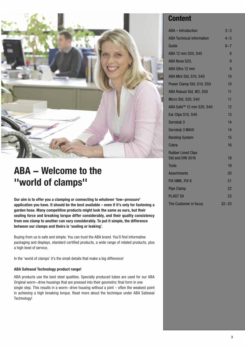
ABA - Welcome to the ''world of clamps'' Our aim is to offer you a clamping or connecting to whatever ‘low-pressure’ application you have. It should be the best available – even if it’s only for fastening a garden hose. Many competitive products might look the same as ours, but their sealing force and breaking torque differ considerably, and their quality consistency from one clamp to another can vary considerably. To put it simple, the difference between our clamps and theirs is ‘sealing or leaking’.
Buying from us is safe and simple. You can trust the ABA brand. You’ll find informative packaging and displays, standard certified products, a wide range of related products, plus a high level of service.
In the ‘world of clamps’ it’s the small details that make a big difference!
ABA Safeseal Technology product range!
ABA products use the best steel qualities. Specially produced tubes are used for our ABA Original worm-drive housings that are pressed into their geometric final form in one single step. This results in a worm-drive housing without a joint – often the weakest point in achieving a high breaking torque. Read more about the technique under ABA Safeseal Technology!
Content
ABA – Introduction 2-3
ABA Technical information 4-5
Guide 6-7
ABA 12 mm S20, S40 8
ABA Nova S20, 9
ABA Ultra 12 mm 9
ABA Mini Std, S10, S40 10
Power Clamp Std, S10, S50 10
ABA Robust Std, W2, S50 11
Micro Std, S20, S40 11
ABA SafeTM 12 mm S20, S40 12
Ear Clips S10, S40 13
Serratub 3 14
Serratub 3 MAXI 14
Banding System 15
Cobra 16
Rubber Lined ClipsStd and DIN 3016 18
Tools 19
Assortments 20
FIX HMK, FIX K 21
Pipe Clamp 22
PLAST SV 23
The Customer in focus 32-33
4
02004006008001000120014001600180020002200240026002800300032003400
2 2,5 3 3,5 4 4,5 5 5,5 6 6,5 7 7,5 8 8,5 9 9,510 10,511 11,Tightening torque (Nm)
Brand X
ABA Average
Din rec, 5Nm
SMS 2298 min
Level C
Level B
Level A
Force
(N)
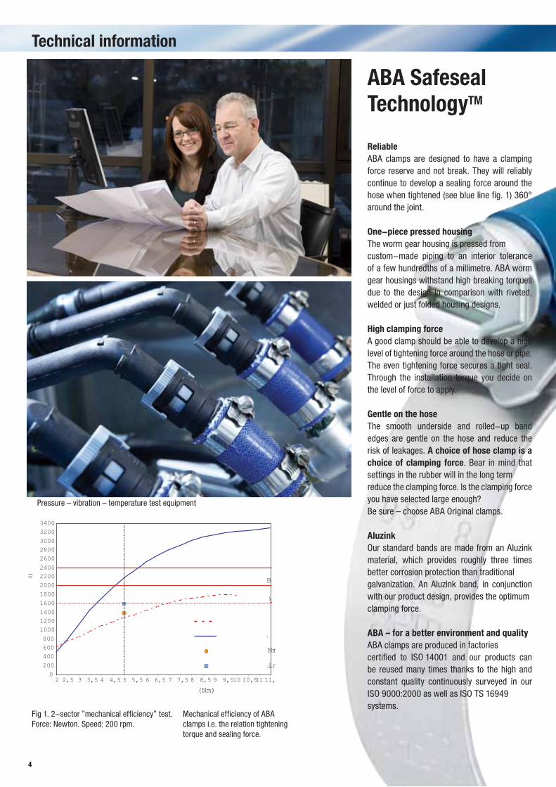
ABA Safeseal TechnologyTM
ReliableABA clamps are designed to have a clamping force reserve and not break. They will reliably continue to develop a sealing force around the hose when tightened (see blue line fig. 1) 360° around the joint.
One-piece pressed housingThe worm gear housing is pressed from custom-made piping to an interior tolerance of a few hundredths of a millimetre. ABA worm gear housings withstand high breaking torques due to the design in comparison with riveted, welded or just folded housing designs.
High clamping forceA good clamp should be able to develop a high level of tightening force around the hose or pipe. The even tightening force secures a tight seal. Through the installation torque you decide on the level of force to apply.
Gentle on the hoseThe smooth underside and rolled-up band edges are gentle on the hose and reduce the risk of leakages. A choice of hose clamp is a choice of clamping force. Bear in mind that settings in the rubber will in the long term reduce the clamping force. Is the clamping force you have selected large enough?Be sure – choose ABA Original clamps.
AluzinkOur standard bands are made from an Aluzink material, which provides roughly three times better corrosion protection than traditional galvanization. An Aluzink band, in conjunction with our product design, provides the optimumclamping force.
ABA – for a better environment and qualityABA clamps are produced in factories certified to ISO 14001 and our products can be reused many times thanks to the high and constant quality continuously surveyed in our ISO 9000:2000 as well as ISO TS 16949 systems.
Technical information
Fig 1. 2-sector ”mechanical efficiency” test.Force: Newton. Speed: 200 rpm.
Mechanical efficiency of ABAclamps i.e. the relation tighteningtorque and sealing force.
Pressure – vibration – temperature test equipment
5
Technical information
Our tests – a guarantee against leakageA hose connection has three components:• Pipe ends – a large number are available
for different purposes.• Hoses – an equally large number are
available.• Naturally, hose clamps with different
characteristics intended for different jobs are also required. ABA Original can be used, with the correct tightening torque, for a large number of applications. ABA Original with aluzink or stainless bands provide a very large clamping force and a leakproof connection. However in some applications you might need a screw-less clamp and then we recommend the Cobra - fast and easy to install.
Clamping force meterIf you wish to compare the clamping force of different products, we can help you on site with our portable measuring equipment. Once the clamping force has been determined, a suitable level of corrosion protection can be selected from the table on next page.
Product development in MaintalWe continuously test systems of hoses, pipe ends, clamps and couplings at our Technical Centre, in order to develop new products and to improve our existing products.
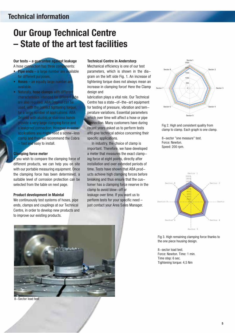
Technical Centre in AnderstorpMechanical efficiency is one of our test parameters, which is shown in the dia-gram on the left side Fig. 1. An increase of tightening torque does not always mean an increase in clamping force! Here the Clamp design andlubrication plays a vital role. Our Technical Centre has a state-of-the-art equipmentfor testing of pressure, vibration and tem-perature variations. Essential parameters which over time will affect a hose or pipe connection. Many customers have during recent years asked us to perform tests and give technical advice concerning their specific applications.
In industry, the choice of clamp is important. Therefore, we have developed a meter that measures the exact clamp-ing force at eight points, directly after installation and over extended periods of time. Tests have shown that ABA prod-ucts achieve high clamping forces before breaking and thus ensure that the cus-tomer has a clamping force reserve in the clamp to avoid blow-off orleakage over time. If you want us to perform tests for your specific need –just contact your Area Sales Manager.
Our Group Technical Centre – State of the art test facilities
8-sector "one-measure" test. Test objects: 10 pcs of ABA Ultra 12mm W1 58-75 clamps.Speed: 650 rpm. Force: Newton. Hose: EPDM. Tightening torque: 5,5 Nm
Note: Cr6 + oil on screw, from ABA stock.
0
500
1000
1500
2000
2500Sector1
Sector 2
Sector 3
Sector 4
Sector 5
Sector 6
Sector 7
Sector 8
Clamp no 1
Clamp no 2
Clamp no 3
Clamp no 4
Clamp no 5
Clamp no 6
Clamp no 7
Clamp no 8
Clamp no 8
Clamp no 9
Clamp no 10
Average 10 clamps
0200400600800100012001400160018002000Sector 1
Sector 2
Sector
Sector 4
Sector 5
Sector 6
Sector 7
Sector 8
Fig 2. High and consistent quality from clamp to clamp. Each graph is one clamp.
8-sector ”one measure” test. Force: Newton. Speed: 200 rpm.
Fig 3. High remaining clamping force thanks to the one piece housing design.
8-sector load test.Force: Newton. Time: 1 min.Time step: 6 sec.Tightening torque: 4,5 Nm
8-Sector load test
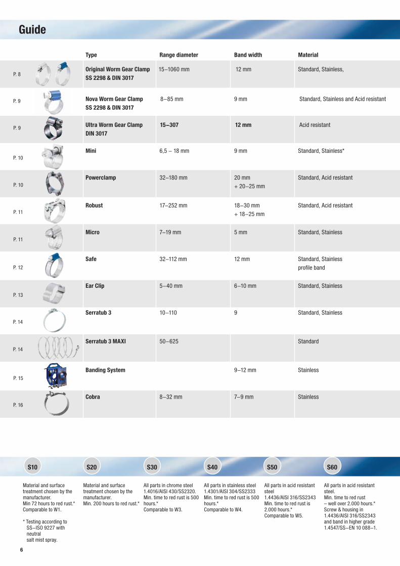
S10 S20 S30 S40 S50 S60
6
Material and surface treatment chosen by the manufacturer. Min 72 hours to red rust.* Comparable to W1.
* Testing according to SS-ISO 9227 with neutral salt mist spray.
Material and surface treatment chosen by the manufacturer. Min. 200 hours to red rust.*
All parts in chrome steel1.4016/AISI 430/SS2320.Min. time to red rust is 500hours.* Comparable to W3.
All parts in stainless steel1.4301/AISI 304/SS2333Min. time to red rust is 500hours.* Comparable to W4.
All parts in acid resistant steel1.4436/AISI 316/SS2343Min. time to red rust is 2.000 hours.* Comparable to W5.
All parts in acid resistant steel.Min. time to red rust – well over 2.000 hours.*Screw & housing in1.4436/AISI 316/SS2343and band in higher grade1.4547/SS-EN 10 088-1.
Guide
Type Range diameter Band width Material
Original Worm Gear Clamp 15-1060 mm 12 mm Standard, Stainless, SS 2298 & DIN 3017
Nova Worm Gear Clamp 8-85 mm 9 mm Standard, Stainless and Acid resistantSS 2298 & DIN 3017
Ultra Worm Gear Clamp 15-307 12 mm Acid resistantDIN 3017
Mini 6,5 - 18 mm 9 mm Standard, Stainless*
Powerclamp 32-180 mm 20 mm Standard, Acid resistant + 20-25 mm
Robust 17-252 mm 18-30 mm Standard, Acid resistant + 18-25 mm
Micro 7-19 mm 5 mm Standard, Stainless
Safe 32-112 mm 12 mm Standard, Stainless profile band
Ear Clip 5-40 mm 6-10 mm Standard, Stainless
Serratub 3 10-110 9 Standard, Stainless
Serratub 3 MAXI 50-625 Standard
Banding System 9-12 mm Stainless
Cobra 8-32 mm 7-9 mm Stainless
P. 8
P. 9
P. 9
P. 10
P. 10
P. 11
P. 11
P. 12
P. 13
P. 14
P. 14
P. 15
P. 16
7
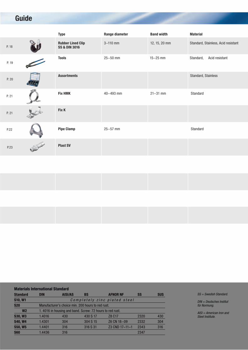
Guide
Materials International StandardStandard DIN AISI/AS BS AFNOR NF SS SUSS10, W1 C o m p l e t e l y z i n c p l a t e d s t e e l
S20 Manufacturer’s choice min. 200 hours to red rust.
W2 1. 4016 in housing and band. Screw: 72 hours to red rust.
S30, W3 1.4016 430 430 S 17 Z8 C17 2320 430
S40, W4 1.4301 304 304 S 15 Z6 CN 18-09 2332 304
S50, W5 1.4401 316 316 S 31 Z3 CND 17-11-1 2343 316
S60 1.4436 316 2347
Type Range diameter Band width Material
Rubber Lined Clip 3-110 mm 12, 15, 20 mm Standard, Stainless, Acid resistantSS & DIN 3016 Tools 25-50 mm 15-25 mm Standard, Acid resistant
Assortments Standard, Stainless
Fix HMK 40-493 mm 21-31 mm Standard
Fix K
Pipe Clamp 25-57 mm Standard
Plast SV
SS = Swedish Standard.
DIN = Deutsches Institut für Normung.
AISI = American Iron and Steel Institute.
P. 18
P. 20
P. 19
P. 21
P. 21
P.22
P.23
8
S20
S40
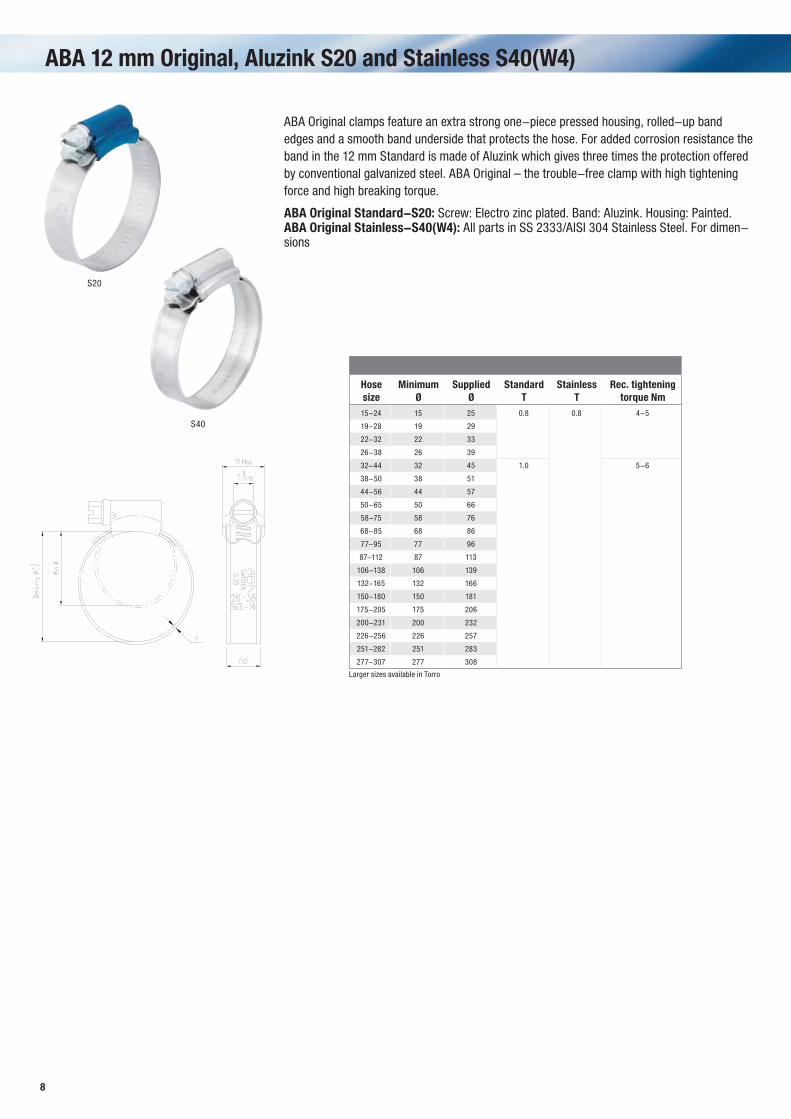
ABA 12 mm Original, Aluzink S20 and Stainless S40(W4)
ABA Original clamps feature an extra strong one-piece pressed housing, rolled-up band edges and a smooth band underside that protects the hose. For added corrosion resistance the band in the 12 mm Standard is made of Aluzink which gives three times the protection offered by conventional galvanized steel. ABA Original – the trouble-free clamp with high tightening force and high breaking torque.
ABA Original Standard-S20: Screw: Electro zinc plated. Band: Aluzink. Housing: Painted.ABA Original Stainless-S40(W4): All parts in SS 2333/AISI 304 Stainless Steel. For dimen-sions
Hose size
Minimum Ø
Supplied Ø
Standard T
Stainless T
Rec. tightening torque Nm
15-24 15 25 0.8 0.8 4-5
19-28 19 29
22-32 22 33
26-38 26 39
32-44 32 45 1.0 5-6
38-50 38 51
44-56 44 57
50-65 50 66
58-75 58 76
68-85 68 86
77-95 77 96
87-112 87 113
106-138 106 139
132-165 132 166
150-180 150 181
175-205 175 206
200-231 200 232
226-256 226 257
251-282 251 283
277-307 277 308
Larger sizes available in Torro

9
ABA Ultra 12 mm Acid Resistant - A High Torque Clamp S50 (W5)
S50
The acid resistant clamp is produced from SS 2343/AISI 316 high tensile strength steel. It has one of the best clamping force ratings in the world thanks to its special thread design and manufacturing methods. Whenever required, this clamp has a very high clamping force and premium corrosion resistance. Every clamp is date stamped for traceability. This clamp has received high praise from US Powerboats and is used worldwide by quality marine equipment manufacturers, amongst others.
ABA Ultra Acid Resistant-S50(W5): All parts are made of SS 2343/AISI 316 stainless steel, in accordance with SS 2298.
Hose size
Minimum Ø
Supplied Ø
Rec. tightening torque Nm
15-24 15 25 2.5-3.5
19-28 19 29
22-32 22 33
26-38 26 39 3.5-4.5
32-44 32 45
38-50 38 51
44-56 44 57 5-6
50-65 50 66
58-75 58 76
68-85 68 86
77-95 77 96
87-112 87 113
104-138 104 139
130-165 130 166
150-180 150 181
175-205 175 206
200-231 200 232
226-256 226 257
251-282 251 283
277-307 277 308
ABA Nova S20, Stainless S40(W4) and Acid Resistant S50(W5)
The highly versatile ABA Nova clamp is an ideal choice for smaller dimensions of hoses. The baseof the housing is cut back and the internal tolerances are very close: a few hundredths of a millimetre. Available for a wide range of hose dimensions, it retains its roundness and sealing qualities even on the smallest of hoses.
ABA Nova Standard-S20(W1): Screw: Electro zinc plated. Band: Galfan. Housing: Painted.ABA Nova Stainless-S40(W4): All parts are made of SS 2333/AISI 304 stainless steel.ABA Nova Acid Resistant-S50(W5): All parts are made of SS 2343/AISI 316 stainless steel.
Standard
Hose size
Minimum Ø
Supplied Ø
Rec. tightening torque Nm
8-14 8 15 2.5-3.5
11-17 10 17
13-20 12 22 3-4
15-24 15 25
19-28 16 28
22-32 20 32
26-38 25 40 4-4,5
32-44 30 45
38-50 32 51
44-56 44 56
50-65 50 65
58-75 58 75
68-85 68 85
Stainless S40(W4)
Hose size
Minimum Ø
Supplied Ø
Rec. tightening torque Nm
8-14 8 15 2.5-3.5
11-17 10 17
13-20 12 22 3-4
15-24 15 25
19-28 16 28
22-32 20 32
26-38 25 40 4-4,5
Acid resistant S50(W5)
Hose size
Minimum Ø
Supplied Ø
Rec. tightening torque Nm
8-14 8 15 2.5-3.5
11-17 10 17
13-20 12 22

10
9 mm
7 mm
9 mm 9 mm7 mm 7 mm
S10
S40
S10
S50
9 mm
7 mm
9 mm 9 mm7 mm 7 mm
20
22
20
22
ABA Mini Standard S10(W1) and Stainless S40(W4)
ABA Mini features rolled-up band edges that are gentle on hoses. The band tongue that fits under the hose is profiled for added strength. The nut is retained even if the screw is removed. Furthermore the screw has a hexagonal head and can be tightened with an flexible socket wrench. The ABA Mini is particularly suitable for use on small, thin-walled hoses. This little clamp provides an excellent clamping force well over screwless clamps.
ABA Mini Standard-S10(W1): Electro zinc plated.ABA Mini Stainless-S40(W4): All parts are made of SS 2333/AISI 304 stainless steel.
Standard - S10
Hose size
Minimum Ø
Supplied Ø
Rec. tightening torque Nm
Mini 7 6,5 7,5 1,5
Mini 8 7 8,5
Mini 9 8 9,5
Mini 10 9 10,5
Mini 11 9,5 11,5
Mini 12 10,5 12,5
Mini 13 11,5 13,5
Mini 14 12,5 14,5
Mini 15 13,5 15,5
Mini 16 14 16,5
Mini 17 15 17,5
Stainless - S40
Hose size
Minimum Ø
Supplied Ø
Rec. tightening torque Nm
Mini 8 7,5 8,5 1,5
Mini 9 8,5 9,5
Mini 10 9,5 11
Mini 11 10,5 12
Mini 12 11,5 13
Mini 13 12,5 14
Mini 14 13,5 15
Mini 15 14,5 16
Mini 16 15 17
Mini 17 16 18
Power Clamp Standard S10(W1) and Acid Resistant S50(W5)
A very strong heavy-duty double band clamp. Also available in a double screw version for extra clamping force. Both “single” and “double” are available in standard version and in stainless steel 316/S50.
Power Clamp - S10(W1): Electro zink platedPower Clamp - S50(W5) : All parts are made of SS2343/AISI 316 stainless steel.
Power Clamp single
MinimumØ
Supplied Ø
Minimum Ø
SuppliedØ
34 40 89 95
39 45 94 100
44 50 99 105
49 55 104 110
54 60 109 115
59 65 114 120
64 70 119 125
69 75 124 130
74 80 129 135
79 85 134 140
84 90 149 155*
Acid resistant not in stock.* Not standard
Power Clamp double
MinimumØ
Supplied Ø
Minimum Ø
SuppliedØ
32 40 105 115
40 50 110 120
45 55 115 125
50 60 120 130
55 65 125 135
60 70 130 140
65 75 135 145
70 80 140 150
75 85 145 155
80 90 150 160
85 95 155 165
90 100 160 170
95 105 165 175
100 110 170 180
11
A
T
ø
≈ 9
5,5
ød
≈ 7,
5
A
T
ø
S20
A
S40
T A
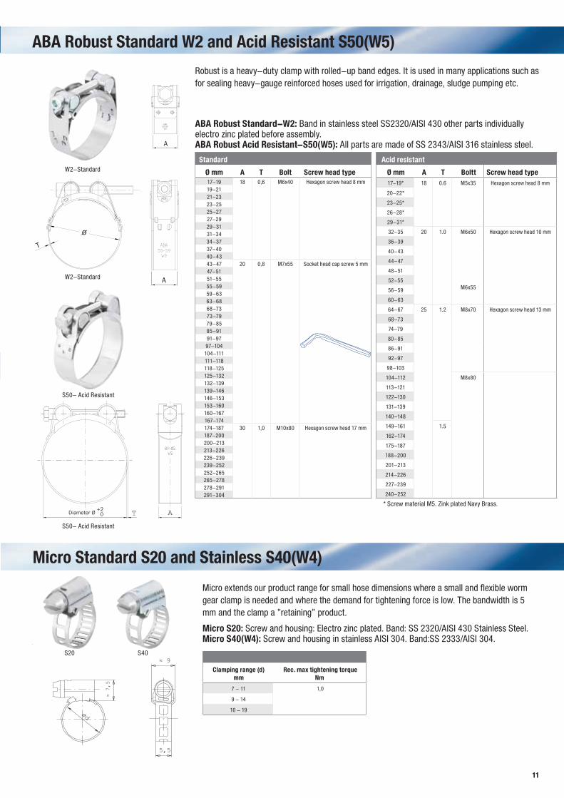
ABA Robust Standard W2 and Acid Resistant S50(W5)
Robust is a heavy-duty clamp with rolled-up band edges. It is used in many applications such as for sealing heavy-gauge reinforced hoses used for irrigation, drainage, sludge pumping etc.
ABA Robust Standard-W2: Band in stainless steel SS2320/AISI 430 other parts individually electro zinc plated before assembly.ABA Robust Acid Resistant-S50(W5): All parts are made of SS 2343/AISI 316 stainless steel.
Acid resistant
Ø mm A T Boltt Screw head type 17-19* 18 0.6 M5x35 Hexagon screw head 8 mm
20-22*
23-25*
26-28*
29-31*
32-35 20 1.0 M6x50 Hexagon screw head 10 mm
36-39
40-43
44-47
48-51
52-55 M6x55
56-59
60-63
64-67 25 1.2 M8x70 Hexagon screw head 13 mm
68-73
74-79
80-85
86-91
92-97
98-103
104-112 M8x80
113-121
122-130
131-139
140-148
149-161 1.5
162-174
175-187
188-200
201-213
214-226
227-239
240-252
Micro Standard S20 and Stainless S40(W4)
Micro extends our product range for small hose dimensions where a small and flexible worm gear clamp is needed and where the demand for tightening force is low. The bandwidth is 5 mm and the clamp a ”retaining” product.
Micro S20: Screw and housing: Electro zinc plated. Band: SS 2320/AISI 430 Stainless Steel.Micro S40(W4): Screw and housing in stainless AISI 304. Band:SS 2333/AISI 304.
Clamping range (d) mm
Rec. max tightening torque Nm
7 - 11 1,0
9 - 14
10 - 19
* Screw material M5. Zink plated Navy Brass.
Standard
Ø mm A T Bolt Screw head type17-19 18 0,6 M6x40 Hexagon screw head 8 mm19-2121-2323-2525-2727-2929-3131-3434-3737-4040-4343-47 20 0,8 M7x55 Socket head cap screw 5 mm47-5151-5555-5959-6363-6868-7373-7979-8585-9191-9797-104104-111111-118118-125125-132132-139139-146146-153153-160160-167167-174174-187 30 1,0 M10x80 Hexagon screw head 17 mm187-200200-213213-226226-239239-252252-265265-278278-291291-304
S50- Acid Resistant
W2-Standard
S50- Acid Resistant
W2-Standard
12
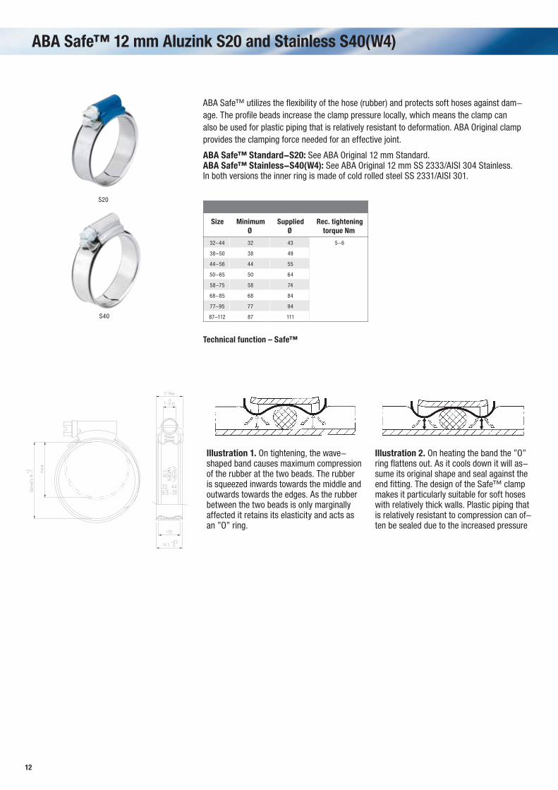
ABA Safe™ 12 mm Aluzink S20 and Stainless S40(W4)
S20
S40
ABA Safe™ utilizes the flexibility of the hose (rubber) and protects soft hoses against dam-age. The profile beads increase the clamp pressure locally, which means the clamp can also be used for plastic piping that is relatively resistant to deformation. ABA Original clamp provides the clamping force needed for an effective joint.
ABA Safe™ Standard-S20: See ABA Original 12 mm Standard.ABA Safe™ Stainless-S40(W4): See ABA Original 12 mm SS 2333/AISI 304 Stainless.In both versions the inner ring is made of cold rolled steel SS 2331/AISI 301.
Size Minimum Ø
Supplied Ø
Rec. tightening torque Nm
32-44 32 43 5-6
38-50 38 49
44-56 44 55
50-65 50 64
58-75 58 74
68-85 68 84
77-95 77 94
87-112 87 111
Illustration 1. On tightening, the wave-shaped band causes maximum compression of the rubber at the two beads. The rubber is squeezed inwards towards the middle and outwards towards the edges. As the rubber between the two beads is only marginally affected it retains its elasticity and acts as an ”O” ring.
Illustration 2. On heating the band the ”O” ring flattens out. As it cools down it will as-sume its original shape and seal against the end fitting. The design of the Safe™ clamp makes it particularly suitable for soft hoses with relatively thick walls. Plastic piping that is relatively resistant to compression can of-ten be sealed due to the increased pressure
Technical function – Safe™
13
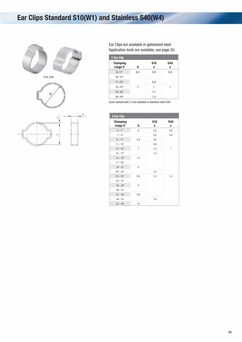
Ear Clips Standard S10(W1) and Stainless S40(W4)
Ds
b
S10, S40
Ear Clips are available in galvanized steel. Application tools are available, see page 20.
1 Ear Clip
Clamping range D b
S10s
S40s
9-11* 6,5 0,8 0,8
10-12*
11-13* 0,9
12-14* 7 1 1
14-16* 1,1
16-18* 1,2
2 Ear Clip
Clamping range D b
S10s
S40s
5 - 7* 6 0,8 0,6
7 - 9 0,6 0,8
9 - 11* 6,5 0,8
11 - 13* 0,9
13 - 15* 7 1,0 1
14 - 17* 1,2
15 - 18* 7,5
17 - 20*
18 - 21 8
20 - 23* 1,3
22 - 25* 8,5 1,4 1,2
23 - 27
25 - 28 9
28 - 31
31 - 34 9,5
34 - 37 1,6
37 - 40 10
Sizes marked with (*) are available in stainless steel S40.
14
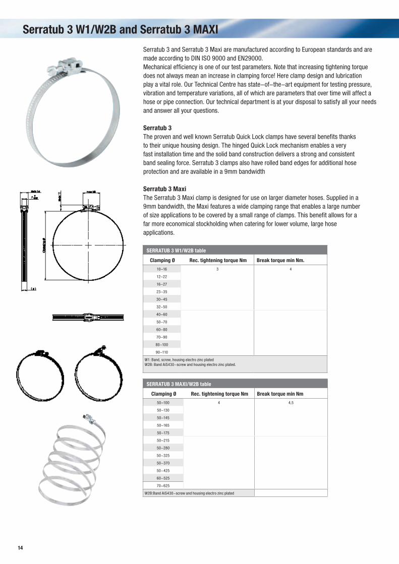
Serratub 3 W1/W2B and Serratub 3 MAXI
Serratub 3 and Serratub 3 Maxi are manufactured according to European standards and are made according to DIN ISO 9000 and EN29000.Mechanical efficiency is one of our test parameters. Note that increasing tightening torque does not always mean an increase in clamping force! Here clamp design and lubrication play a vital role. Our Technical Centre has state-of-the-art equipment for testing pressure, vibration and temperature variations, all of which are parameters that over time will affect a hose or pipe connection. Our technical department is at your disposal to satisfy all your needs and answer all your questions.
Serratub 3The proven and well known Serratub Quick Lock clamps have several benefits thanksto their unique housing design. The hinged Quick Lock mechanism enables a veryfast installation time and the solid band construction delivers a strong and consistentband sealing force. Serratub 3 clamps also have rolled band edges for additional hoseprotection and are available in a 9mm bandwidth
Serratub 3 Maxi The Serratub 3 Maxi clamp is designed for use on larger diameter hoses. Supplied in a9mm bandwidth, the Maxi features a wide clamping range that enables a large numberof size applications to be covered by a small range of clamps. This benefit allows for afar more economical stockholding when catering for lower volume, large hoseapplications.
SERRATUB 3 W1/W2B table
Clamping Ø Rec. tightening torque Nm Break torque min Nm.
10-16 3 4
12-22
16-27
23-35
30-45
32-50
40-60
50-70
60-80
70-90
80-100
90-110
W1: Band, screw, housing electro zinc platedW2B: Band AiS430-screw and housing electro zinc plated.
SERRATUB 3 MAXI/W2B table
Clamping Ø Rec. tightening torque Nm Break torque min Nm
50-100 4 4,5
50-130
50-145
50-165
50-175
50-215
50-280
50-325
50-370
50-425
60-525
70-625
W2B:Band AiS430-screw and housing electro zinc plated

15
Banding System
An instant solution for clamping. The Banding System offers you the immediate possibility to make your own clamp from the components. Ideal for service and maintenance. Each system is supplied in a dispenser box containing a full length of band and a number of the unique quick-lock housings with screw. The band is perforated, flexible and in stainless steel. Avail-able in 9 or 12 mm bandwidths.
Banding System/W2B: Screw and housing: Electro zink plated and chromated.Band: AISI 430.
W2B
Bandwidth Description
9 mm KIT 3 meters with 8 quick-lock housings
12 mm KIT 3 meters with 6 quick-lock housings
9 mm KIT 5 meters with 8 quick-lock housings
12 mm KIT 5 meters with 6 quick-lock housings
9 mm Bandbox containing 25 meters
12 mm Bandbox containing 25 meters
9 mm Quick-lock housing box 100 pcs
12 mm Quick-lock housing box 100 pcs
The smart quick-lock housing is outstanding for this type of banding system.
16
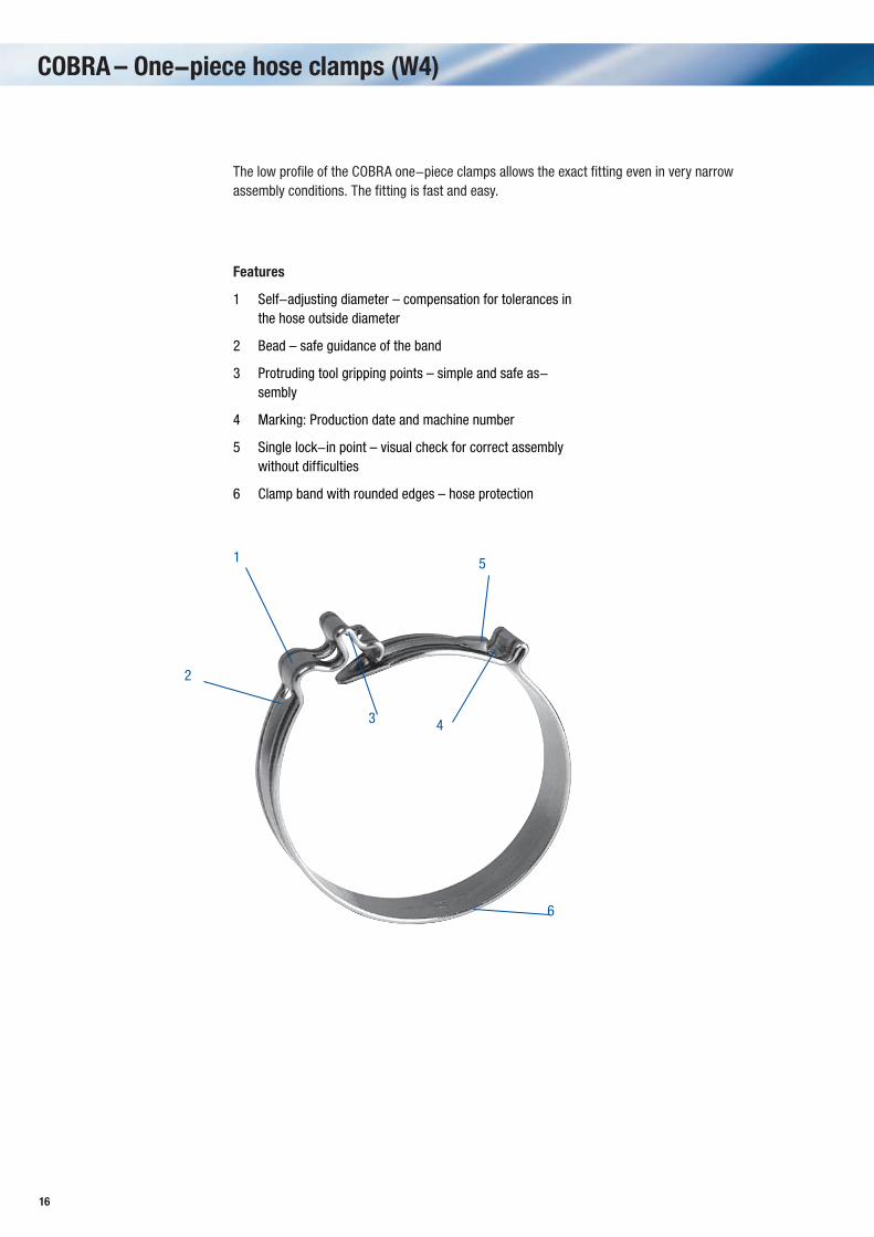
COBRA – One-piece hose clamps (W4)
1
➋2
➋6
➋4
➋5
➋3
The low profile of the COBRA one-piece clamps allows the exact fitting even in very narrow assembly conditions. The fitting is fast and easy.
Features
➋1 Self-adjusting diameter – compensation for tolerances in the hose outside diameter
2 Bead – safe guidance of the band
3 Protruding tool gripping points – simple and safe as-sembly
4 Marking: Production date and machine number
5 Single lock-in point – visual check for correct assembly without difficulties
6 Clamp band with rounded edges – hose protection
17
Band- width
Description, ordercode Nominal diameter d1
Clamping Range Da(hose outside-ø)
(mm) in mm in Inches7 COBRA 7.5/7 W4 8.0–9.0 5/16–3/8
7 COBRA 8.5/7 W4 8.5–9.5 5/16–3/8
7 COBRA 8.5/7 W4 9.0–10.0 3/8–3/8
7 COBRA 9/7 W4 9.5–10.5 3/8–3/8
7 COBRA 9.5/7 W4 10.0–11.0 3/8–7/16
7 COBRA 10/7 W4 10.5–11.5 3/8–7/16
7 COBRA 10.5/7 W4 11.0–12.0 7/16–1/2
7 COBRA 11/7 W4 11.5–12.5 7/16–1/2
7 COBRA 11.5/7 W4 12.0–13.0 1/2–1/2
8 COBRA 11.5/8 W4 12.0–13.5 1/2–1/2
8 COBRA 12/8 W4 12.5–14.0 1/2–9/16
8 COBRA 13/8 W4 13.5–15.0 1/2–5/8
8 COBRA 14/8 W4 14.5–16.0 9/16–5/8
8 COBRA 15/8 W4 15.5–17.0 5/8–11/16
8 COBRA 16/8 W4 16.5–18.0 5/8–3/4
8 COBRA 17/8 W4 17.5–19.0 11/16–3/4
8 COBRA 18/8 W4 18.5–20.0 3/4–13/16
8 COBRA 19/8 W4 19.5–21.0 3/4–13/16
8 COBRA 20/8 W4 20.5–22.0 13/16–7/8
8 COBRA 21/8 W4 21.5–23.0 13/16–7/8
8 COBRA 22/8 W4 22.5–24.0 7/8–15/16
8 COBRA 23/8 W4 23.5–25.0 7/8–1
8 COBRA 24/8 W4 24.5–26.0 15/16–11/16
8 COBRA 25/8 W4 25.5–27.0 1–11/16
8 COBRA 26/8 W4 26.5–28.0 11/16–11/8
8 COBRA 27/8 W4 27.5–29.0 11/16–11/8
8 COBRA 28/8 W4 28.5–30.0 11/8–13/16
8 COBRA 29/8 W4 29.5–31.0 11/8–11/4
8 COBRA 30/8 W4 30.5–32.0 13/16–11/4
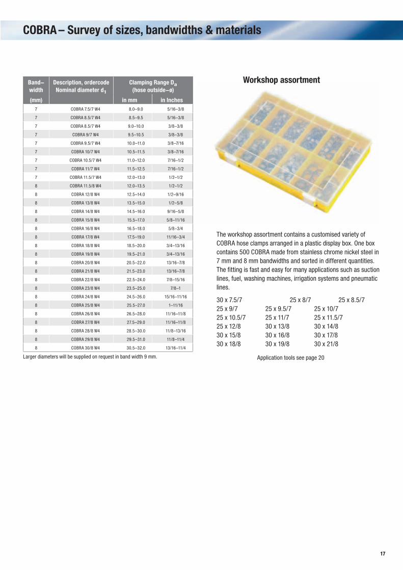
Workshop assortment
The workshop assortment contains a customised variety of COBRA hose clamps arranged in a plastic display box. One box contains 500 COBRA made from stainless chrome nickel steel in 7 mm and 8 mm bandwidths and sorted in different quantities. The fitting is fast and easy for many applications such as suction lines, fuel, washing machines, irrigation systems and pneumatic lines.
30 x 7.5/7 25 x 8/7 25 x 8.5/725 x 9/7 25 x 9.5/7 25 x 10/725 x 10.5/7 25 x 11/7 25 x 11.5/725 x 12/8 30 x 13/8 30 x 14/830 x 15/8 30 x 16/8 30 x 17/830 x 18/8 30 x 19/8 30 x 21/8
Application tools see page 20Larger diameters will be supplied on request in band width 9 mm.
COBRA – Survey of sizes, bandwidths & materials
18
D1 E1 F1
D2 E2 F2
A1 B1 C1
A2 B2 C2
M
d
➋
dn b1
d
D1
E1 F1
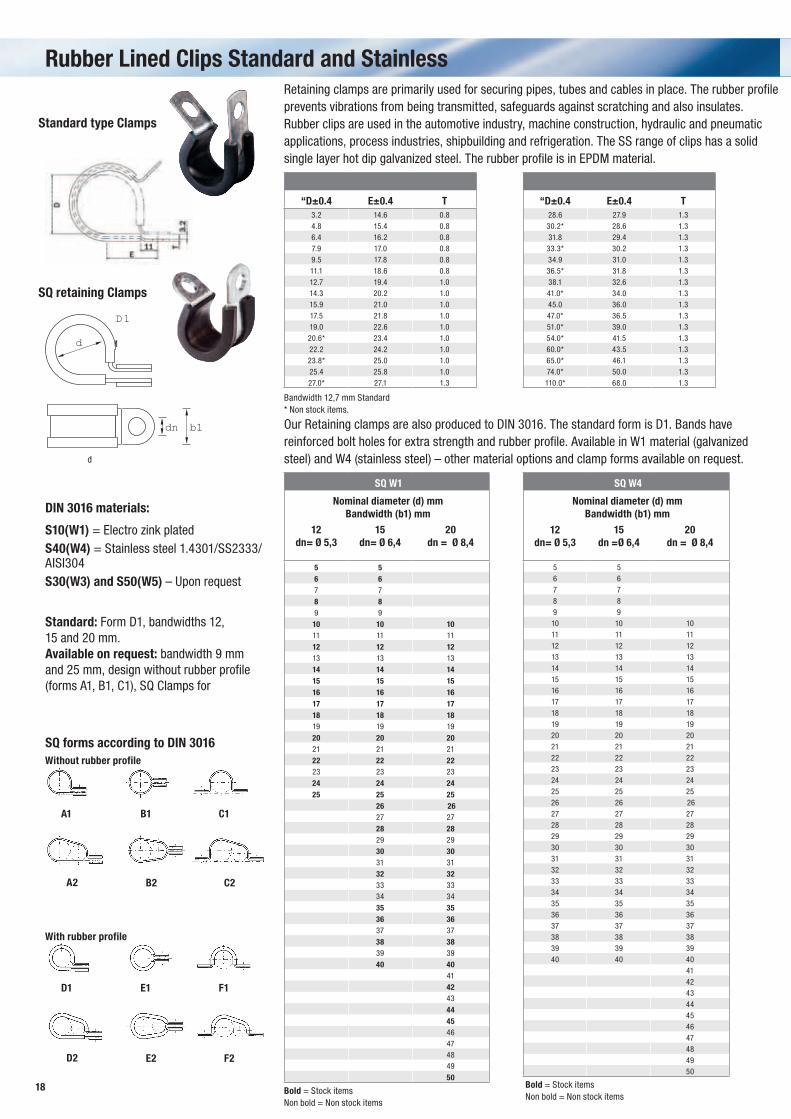
Rubber Lined Clips Standard and StainlessRetaining clamps are primarily used for securing pipes, tubes and cables in place. The rubber profile prevents vibrations from being transmitted, safeguards against scratching and also insulates. Rubber clips are used in the automotive industry, machine construction, hydraulic and pneumatic applications, process industries, shipbuilding and refrigeration. The SS range of clips has a solid single layer hot dip galvanized steel. The rubber profile is in EPDM material.
Bandwidth 12,7 mm Standard* Non stock items.
Standard type Clamps
SQ retaining Clamps
Our Retaining clamps are also produced to DIN 3016. The standard form is D1. Bands have reinforced bolt holes for extra strength and rubber profile. Available in W1 material (galvanized steel) and W4 (stainless steel) – other material options and clamp forms available on request.
DIN 3016 materials:
S10(W1) = Electro zink platedS40(W4) = Stainless steel 1.4301/SS2333/AISI304S30(W3) and S50(W5) – Upon request
Standard: Form D1, bandwidths 12,15 and 20 mm.Available on request: bandwidth 9 mmand 25 mm, design without rubber profile(forms A1, B1, C1), SQ Clamps for
Without rubber profile
With rubber profile
SQ forms according to DIN 3016
SQ W1
Nominal diameter (d) mm Bandwidth (b1) mm
12dn= Ø 5,3
15dn= Ø 6,4
20dn = Ø 8,4
5 56 67 7
8 89 9
10 10 1011 11 11
12 12 1213 13 13
14 14 1415 15 1516 16 1617 17 1718 18 1819 19 19
20 20 2021 21 21
22 22 2223 23 23
24 24 2425 25 25
26 2627 27
28 2829 29
30 3031 31
32 3233 3334 34
35 3536 3637 37
38 3839 39
40 4041
4243
444546474849
50
Bold = Stock itemsNon bold = Non stock items
Bold = Stock itemsNon bold = Non stock items
“D±0.4 E±0.4 T3.2 14.6 0.84.8 15.4 0.86.4 16.2 0.87.9 17.0 0.89.5 17.8 0.811.1 18.6 0.812.7 19.4 1.014.3 20.2 1.015.9 21.0 1.017.5 21.8 1.019.0 22.6 1.020.6* 23.4 1.022.2 24.2 1.023.8* 25.0 1.025.4 25.8 1.027.0* 27.1 1.3
“D±0.4 E±0.4 T28.6 27.9 1.330.2* 28.6 1.331.8 29.4 1.333.3* 30.2 1.334.9 31.0 1.336.5* 31.8 1.338.1 32.6 1.341.0* 34.0 1.345.0 36.0 1.347.0* 36.5 1.351.0* 39.0 1.354.0* 41.5 1.360.0* 43.5 1.365.0* 46.1 1.374.0* 50.0 1.3110.0* 68.0 1.3
SQ W4
Nominal diameter (d) mm Bandwidth (b1) mm
12dn= Ø 5,3
15dn =Ø 6,4
20dn = Ø 8,4
5 56 67 78 89 910 10 1011 11 1112 12 1213 13 1314 14 1415 15 1516 16 1617 17 1718 18 1819 19 1920 20 2021 21 2122 22 2223 23 2324 24 2425 25 2526 26 2627 27 2728 28 2829 29 2930 30 3031 31 3132 32 3233 33 3334 34 3435 35 3536 36 3637 37 3738 38 3839 39 3940 40 40
41424344454647484950

19
Tools
Ear Clip pliers
Flexidriver 25 cm
Flexidriver 60 cm
COBRA – pneumatic pliersThe pneumatic pliers, available in a 0° version (Fig. 1), an extended 0° version (Fig. 2) and a 90° version (not shown), are the ideal tools for industrial use.
Fig. 1
Fig. 2
COBRA – hand tool
Robust key
20
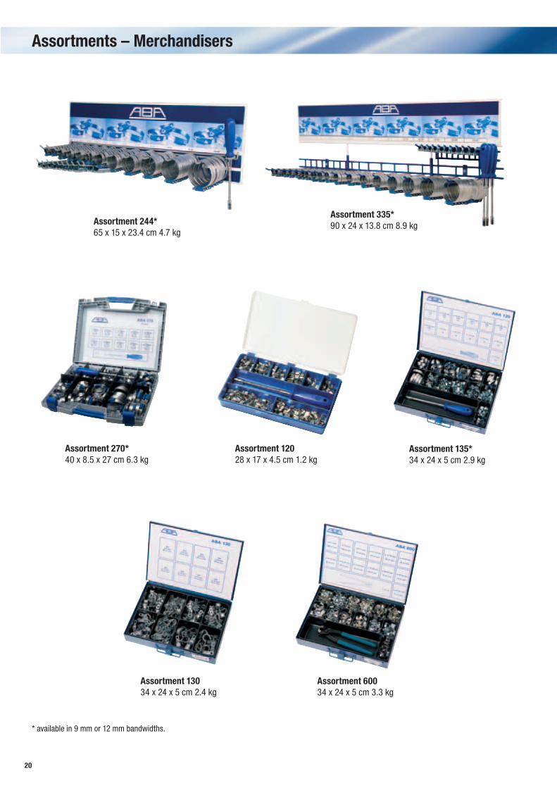
Assortments – Merchandisers
Assortment 244*65 x 15 x 23.4 cm 4.7 kg
Assortment 335*90 x 24 x 13.8 cm 8.9 kg
Assortment 270*40 x 8.5 x 27 cm 6.3 kg
Assortment 12028 x 17 x 4.5 cm 1.2 kg
Assortment 135*34 x 24 x 5 cm 2.9 kg
Assortment 13034 x 24 x 5 cm 2.4 kg
Assortment 60034 x 24 x 5 cm 3.3 kg
* available in 9 mm or 12 mm bandwidths.
21
t
dE
B
s
SA
h
L
BA
a
M
D
ø
Assortment 135*34 x 24 x 5 cm 2.9 kg
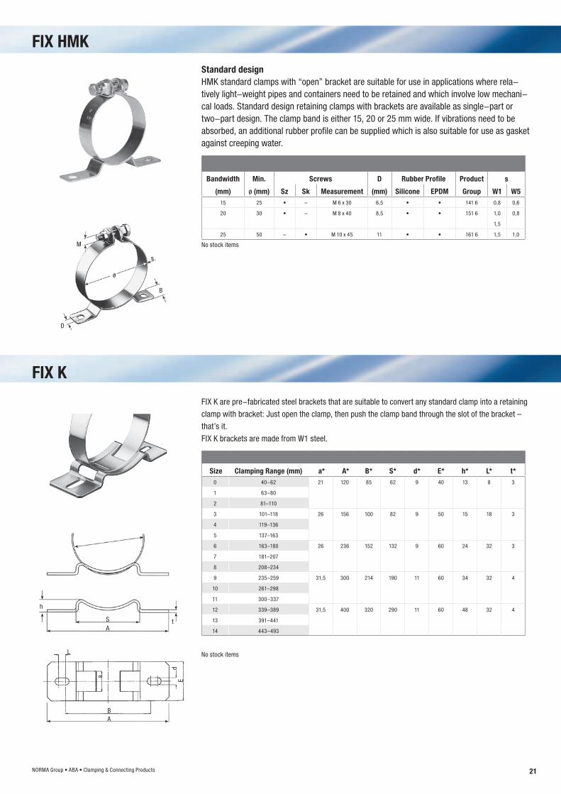
Bandwidth Min. Screws D Rubber Profile Product s
(mm) ø (mm) Sz Sk Measurement (mm) Silicone EPDM Group W1 W5 15 25 • – M 6 x 30 6,5 • • 141 6 0,8 0,6
20 30 • – M 8 x 40 8,5 • • 151 6 1,0 0,8
1,5
25 50 – • M 10 x 45 11 • • 161 6 1,5 1,0
Standard designHMK standard clamps with “open” bracket are suitable for use in applications where rela-tively light-weight pipes and containers need to be retained and which involve low mechani-cal loads. Standard design retaining clamps with brackets are available as single-part or two-part design. The clamp band is either 15, 20 or 25 mm wide. If vibrations need to be absorbed, an additional rubber profile can be supplied which is also suitable for use as gasket against creeping water.
FIX K are pre-fabricated steel brackets that are suitable to convert any standard clamp into a retaining
clamp with bracket: Just open the clamp, then push the clamp band through the slot of the bracket –
that’s it.
FIX K brackets are made from W1 steel.
Size Clamping Range (mm) a* A* B* S* d* E* h* L* t*0 40–62 21 120 85 62 9 40 13 8 3
1 63–80
2 81–110
3 101–118 26 156 100 82 9 50 15 18 3
4 119–136
5 137–163
6 163–180 26 236 152 132 9 60 24 32 3
7 181–207
8 208–234
9 235–259 31,5 300 214 190 11 60 34 32 4
10 261–298
11 300–337
12 339–389 31,5 400 320 290 11 60 48 32 4
13 391–441
14 443–493
FIX HMK
FIX K
No stock items
No stock items
NORMA Group • ABA • Clamping & Connecting Products
22
Pipe Clamp, M8
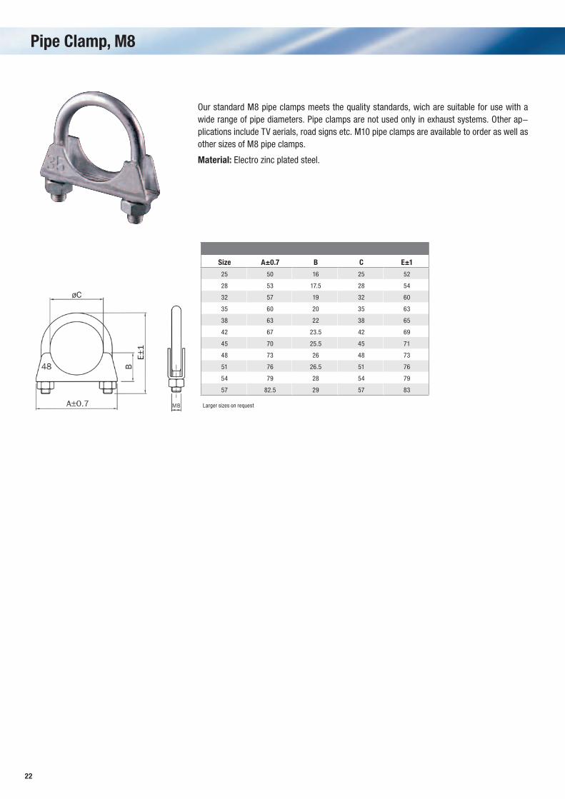
Our standard M8 pipe clamps meets the quality standards, wich are suitable for use with a wide range of pipe diameters. Pipe clamps are not used only in exhaust systems. Other ap-plications include TV aerials, road signs etc. M10 pipe clamps are available to order as well as other sizes of M8 pipe clamps.
Material: Electro zinc plated steel.
Size A±0.7 B C E±1
25 50 16 25 52
28 53 17.5 28 54
32 57 19 32 60
35 60 20 35 63
38 63 22 38 65
42 67 23.5 42 69
45 70 25.5 45 71
48 73 26 48 73
51 76 26.5 51 76
54 79 28 54 79
57 82.5 29 57 83
Larger sizes on request
23
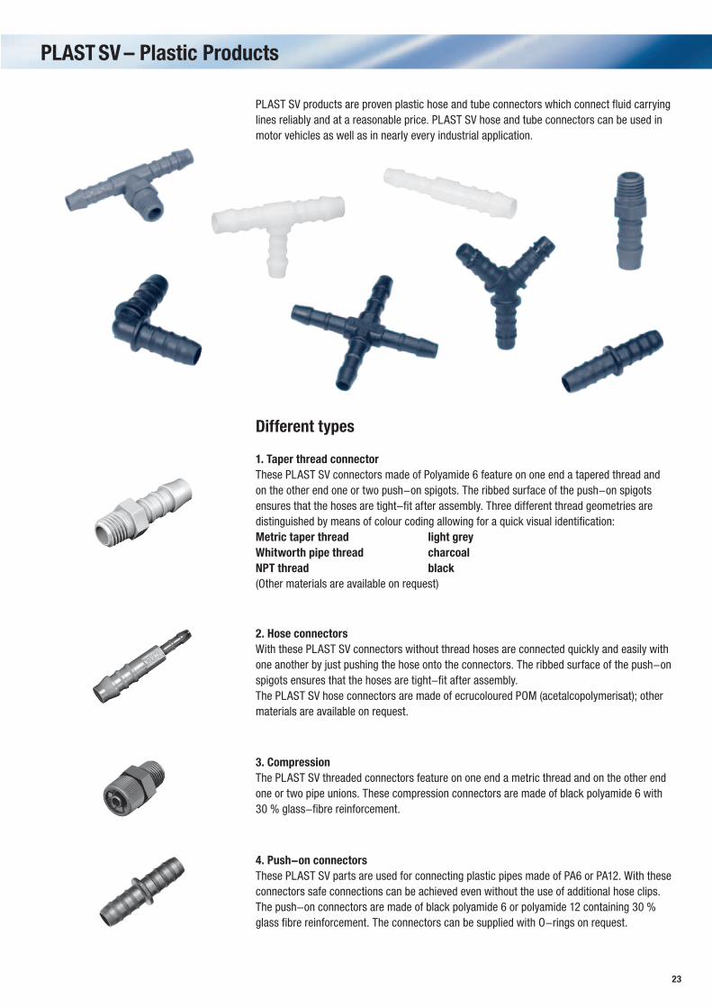
PLAST SV products are proven plastic hose and tube connectors which connect fluid carrying lines reliably and at a reasonable price. PLAST SV hose and tube connectors can be used in motor vehicles as well as in nearly every industrial application.
Different types
1. Taper thread connectorThese PLAST SV connectors made of Polyamide 6 feature on one end a tapered thread and on the other end one or two push-on spigots. The ribbed surface of the push-on spigots ensures that the hoses are tight-fit after assembly. Three different thread geometries are distinguished by means of colour coding allowing for a quick visual identification: Metric taper thread light greyWhitworth pipe thread charcoalNPT thread black(Other materials are available on request)
2. Hose connectorsWith these PLAST SV connectors without thread hoses are connected quickly and easily with one another by just pushing the hose onto the connectors. The ribbed surface of the push-on spigots ensures that the hoses are tight-fit after assembly.The PLAST SV hose connectors are made of ecrucoloured POM (acetalcopolymerisat); other materials are available on request.
3. CompressionThe PLAST SV threaded connectors feature on one end a metric thread and on the other end one or two pipe unions. These compression connectors are made of black polyamide 6 with 30 % glass-fibre reinforcement.
4. Push-on connectorsThese PLAST SV parts are used for connecting plastic pipes made of PA6 or PA12. With these connectors safe connections can be achieved even without the use of additional hose clips. The push-on connectors are made of black polyamide 6 or polyamide 12 containing 30 % glass fibre reinforcement. The connectors can be supplied with O-rings on request.
PLAST SV – Plastic Products
24
PLAST – Product & Material Properties
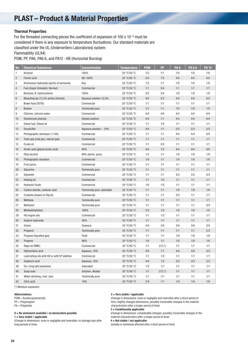
Thermal PropertiesFor the threaded connecting pieces the coefficient of expansion of 100 x 10-6 must be considered if there is any exposure to temperature fluctuations. Our standard materials are classified under the UL (Underwriters Laboratories) system: Flammability (UL94) POM, PP, PA6, PA6.6, and PA12 : HB (Horizontal Burning)
No. Chemical Substance Concentration Temperature POM PP PA 6 PA 6.6 PA 12
1 Acetone 100% 20 °C/50 °C 1/3 1/1 1/0 1/0 1/0
2 Formic acid 98–100% 20 °C/50 °C 4/4 1/3 4/4 4/4 4/4
3 Ammonium hydroxide (spirits of ammonia) Any 20 °C/50 °C 1/2 1/1 1/0 1/0 1/0
4 Fuel (Super Unleaded, Normal) Commercial 20 °C/50 °C 1/1 3/4 1/1 1/1 1/1
5 Benzene, B. hydrocarbons 100% 20 °C/50 °C 3/3 3/4 1/0 1/0 1/0
6 Bleaching lye (12.5% active chlorine) Aqueous solution 12,5% 20 °C/50 °C 4/4 3/3 4/4 4/4 3/3
7 Brake fluid (DOT4) Commercial 20 °C/50 °C 1/1 1/1 1/1 1/1 1/1
8 Butane Technically pure 20 °C/50 °C 1/2 1/1 1/0 1/0 1/0
9 Chlorine, chlorine water Commercial 20 °C/50 °C 4/4 4/4 4/4 4/4 4/4
10 Disinfectant phenols Diluted solution 20 °C/50 °C 4/4 1/1 4/4 4/4 4/4
11 Diesel fuel, Diesel oil Commercial 20 °C/50 °C 1/1 1/3 1/1 1/1 1/1
12 Decalcifier Aqueous solution ~ 10% 20 °C/50 °C 4/4 1/1 2/3 2/3 2/3
13 Photographic developer (1:100) Commercial 20 °C/50 °C 1/1 1/1 4/4 4/4 4/4
14 Town gas (coal gas, natural gas) Commercial 20 °C/50 °C 1/1 1/1 1/1 1/1 1/1
15 Crude oil Commercial 20 °C/50 °C 1/1 3/3 1/1 1/1 1/1
16 Acetic acid (glacial acetic acid) 90% 20 °C/50 °C 4/4 1/2 4/4 4/4 4/4
17 Ethyl alcohol 96% (techn. pure) 20 °C/50 °C 1/2 1/1 1/0 1/0 1/0
18 Photographic emulsion Commercial 20 °C/50 °C 1/0 1/1 1/0 1/0 1/0
19 Fruit juices Commercial 20 °C/50 °C 1/1 1/1 1/1 1/1 1/1
20 Glycerine Technically pure 20 °C/50 °C 1/1 1/1 1/1 1/1 1/1
21 Glysantin Commercial 20 °C/50 °C 1/1 1/1 3/3 3/3 3/3
22 Heating oil Commercial 20 °C/50 °C 1/1 1/3 1/1 1/1 1/1
23 Hydraulic fluids Commercial 20 °C/50 °C 1/0 1/3 1/1 1/1 1/1
24 Carbon dioxide, carbonic acid Technically pure, saturated 20 °C/50 °C 1/1 1/1 1/0 1/0 1/0
25 Coolants (based on Glycol) Commercial 20 °C/50 °C 1/1 1/1 3/3 1/1 1/1
26 Methane Technically pure 20 °C/50 °C 1/1 1/1 1/1 1/1 1/1
27 Methanol Technically pure 20 °C/50 °C 1/1 1/1 1/1 1/1 3/3
28 Methylethylketon 100% 20 °C/50 °C 3/3 1/3 1/0 1/0 1/0
29 HD engine oils Commercial 20 °C/50 °C 1/1 1/3 1/1 1/1 1/1
30 Sodium hydroxide 40% 20 °C/50 °C 1/1 1/1 1/1 1/1 1/1
31 Ozone Gaseous 20 °C/50 °C 4/4 3/4 3/4 3/4 3/4
32 Propanol Technically pure 20 °C/50 °C 1/1 1/1 1/1 1/1 2/2
33 Propane (liquefied gas) Fluid 20 °C/50 °C 1/1 1/1 1/0 1/0 1/0
34 Propene 96% 20 °C/50 °C 1/0 1/1 1/0 1/0 1/0
35 Rape oil (RME) Commercial 20 °C/50 °C 1/1 2/2 (*) 1/1 1/1 1/1
36 Hydrochloric acid Aqueous, 10% 20 °C/50 °C 4/4 1/1 4/4 4/4 3/3
37 Lubricating oils with HD or with EP additive Commercial 20 °C/50 °C 1/1 1/2 1/1 1/1 1/1
38 Sulphuric acid Aqueous, 10% 20 °C/50 °C 4/4 1/2 3/3 3/3 2/2
39 De-icing salt (solutions) Saturated 20 °C/50 °C 1/2 1/1 1/1 1/1 1/1
40 Soap suds Solution, diluted 20 °C/50 °C 1/1 2/2 (*) 1/1 1/1 1/1
41 Water (drinking, river, sea) Technically pure 20 °C/50 °C 1/1 1/1 1/1 1/1 1/1
42 Citric acid 10% 20 °C/50 °C 2/4 1/1 1/0 1/0 1/0
(*) Moisture expansion
Abbreviations:POM = AcetalcopolymerisatPP = PolypropylenPA = Polyamide
0 = No statement available / no declaration possible1 = Very stable / applicable(Change in dimensions: none or negligible and reversible; no damage also after long periods of time)
2 = Very stable / applicable(Change in dimensions: none or negligible and reversible after a short period of time; slightly changed dimensions, possibly irreversible changes in the material characteristics after a longer period of time)3 = Conditionally applicable(Change in dimensions: considerable changes; possibly irreversible changes in the material characteristics after a longer period of time)4 = Not stable / not applicable(soluble or extremely affected after a short period of time)
25
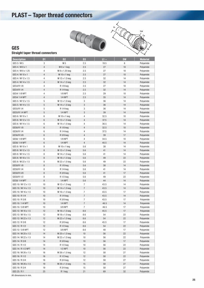
PLAST – Taper thread connectors
GESStraight taper thread connectors
Description D1 D2 D3 L1 ~ SW Material GES 3 / M 5 3 M 5 2.5 19.5 6 Polyamide
GES 4 / M 8 x 1 4 M 8 x 1 keg 2.5 27 10 Polyamide
GES 4 / M 8 x 1.25 4 M 8 x 1.25 keg 2.5 27 10 Polyamide
GES 4 / M 10 x 1 4 M 10 x 1 keg 2.5 27 10 Polyamide
GES 4 / M 12 x 1.5 4 M 12 x 1.5 keg 2.5 32 14 Polyamide
GES 4 / M 14 x 1.5 4 M 14 x 1.5 keg 2.5 32 14 Polyamide
GES4/R 1/8 4 R 1/8 keg 2.5 27 10 Polyamide
GES4/R 1/4 4 R 1/4 keg 2.5 32 14 Polyamide
GES4/ 1/8 NPT 4 1/8 NPT 2.5 29 10 Polyamide
GES4/ 1/4 NPT 4 1/4 NPT 2.5 35 14 Polyamide
GES 5 / M 12 x 1.5 5 M 12 x 1.5 keg 3 36 14 Polyamide
GES 5 / M 14 x 1.5 5 M 14 x 1.5 keg 3 36 14 Polyamide
GES5/R 1/4 5 R 1/4 keg 3 36 14 Polyamide
GES5/R 1/4 NPT 5 1/4 NPT 3 39 14 Polyamide
GES 6 / M 10 x 1 6 M 10 x 1 keg 4 32.5 10 Polyamide
GES 6 / M 12 x 1.5 6 M 12 x 1.5 keg 4 37.5 14 Polyamide
GES 6 / M 14 x 1.5 6 M 14 x 1.5 keg 4 36.5 14 Polyamide
GES6/R 1/8 6 R 1/8 keg 4 32.5 10 Polyamide
GES6/R 1/4 6 R 1/4 keg 4 37.5 14 Polyamide
GES6/R 3/8 6 R 3/8 keg 4 39 17 Polyamide
GES6/ 1/8 NPT 6 1/8 NPT 4 34.5 10 Polyamide
GES6/ 1/4 NPT 6 1/4 NPT 4 40.5 14 Polyamide
GES 8 / M 10 x 1 8 M 10 x 1 keg 5.6 38 14 Polyamide
GES 8 / M 12 x 1.5 8 M 12 x 1.5 keg 5.6 41 14 Polyamide
GES 8 / M 14 x 1.5 8 M 14 x 1.5 keg 5.6 41 14 Polyamide
GES 8 / M 18 x 1.5 8 M 18 x 1.5 keg 5.6 49 22 Polyamide
GES 8 / M 22 x 1.5 8 M 22 x 1.5 keg 5.6 49 22 Polyamide
GES8/R 1/8 8 R 1/8 keg 5.6 38 14 Polyamide
GES8/R 1/4 8 R 1/4 keg 5.6 41 14 Polyamide
GES8/R 3/8 8 R 3/8 keg 5.6 41 17 Polyamide
GES8/R 1/2 8 R 1/2 keg 5.6 49 22 Polyamide
GES8/ 1/4 NPT 8 1/4 NPT 5.6 44 14 Polyamide
GES 10 / M 12 x 1.5 10 M 12 x 1.5 keg 7 43.5 14 Polyamide
GES 10 / M 14 x 1.5 10 M 14 x 1.5 keg 7 43.5 14 Polyamide
GES 10 / M 16 x 1.5 10 M 16 x 1.5 keg 7 43.5 17 Polyamide
GES 10 / R 1/4 10 R 1/4 keg 7 43.5 14 Polyamide
GES 10 / R 3/8 10 R 3/8 keg 7 43.5 17 Polyamide
GES 10 / 1/4 NPT 10 1/4 NPT 7 46.5 14 Polyamide
GES 10 / 3/8 NPT 10 3/8 NPT 7 46.5 17 Polyamide
GES 12 / M 16 x 1.5 12 M 16 x 1.5 keg 8.6 45.5 17 Polyamide
GES 12 / M 18 x 1.5 12 M 18 x 1.5 keg 8.6 54 22 Polyamide
GES 12 / M 22 x 1.5 12 M 22 x 1.5 keg 8.6 54 22 Polyamide
GES 12 / R 3/8 12 R 3/8 keg 8.6 45.5 17 Polyamide
GES 12 / R 1/2 12 R 1/2 keg 8.6 54 22 Polyamide
GES 12 / 3/8 NPT 12 3/8 NPT 8.6 48 17 Polyamide
GES 14 / M 20 x 1.5 14 M 20 x 1.5 keg 10 56 22 Polyamide
GES 14 / M 22 x 1.5 14 M 22 x 1.5 keg 10 56 22 Polyamide
GES 14 / R 3/8 14 R 3/8 keg 10 56 17 Polyamide
GES 14 / R 1/2 14 R 1/2 keg 10 56 22 Polyamide
GES 14 / R 1/2 NPT 14 1/2 NPT 10 56 22 Polyamide
GES 16 / M 26 x 1.5 16 M 26 x 1.5 keg 12 58 27 Polyamide
GES 16 / R 1/2 16 R 1/2 keg 12 58 22 Polyamide
GES 16 / R 3/4 16 R 3/4 keg 12 58 27 Polyamide
GES 19 / M 26 x 1.5 19 M 26 x 1.5 keg 15 58 27 Polyamide
GES 19 / R 3/4 19 R 3/4 keg 15 58 27 Polyamide
GES 25 / R 1 25 R 1 keg 21 69 32 Polyamide
All dimensions in mm.
26
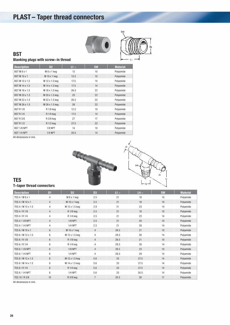
PLAST – Taper thread connectors
BSTBlanking plugs with screw-in thread
Description D2 L1 ~ SW Material BST M 8 x 1 M 8 x 1 keg 13 10 Polyamide
BST M 10 x 1 M 10 x 1 keg 13.5 10 Polyamide
BST M 12 x 1.5 M 12 x 1.5 keg 17.5 14 Polyamide
BST M 14 x 1.5 M 14 x 1.5 keg 17.5 14 Polyamide
BST M 18 x 1.5 M 18 x 1.5 keg 26.5 22 Polyamide
BST M 20 x 1.5 M 20 x 1.5 keg 25 22 Polyamide
BST M 22 x 1.5 M 22 x 1.5 keg 26.5 22 Polyamide
BST M 26 x 1.5 M 26 x 1.5 keg 26 22 Polyamide
BST R 1/8 R 1/8 keg 12.5 10 Polyamide
BST R 1/4 R 1/4 keg 17.5 14 Polyamide
BST R 3/8 R 3/8 keg 27 17 Polyamide
BST R 1/2 R 1/2 keg 27.5 22 Polyamide
BST 1/8 NPT 1/8 NPT 14 10 Polyamide
BST 1/4 NPT 1/4 NPT 20.5 14 Polyamide
Description D1 D2 D3 L1 ~ L4 ~ SW Material TES 4 / M 8 x 1 4 M 8 x 1 keg 2.5 21 18 10 Polyamide
TES 4 / M 10 x 1 4 M 10 x 1 keg 2.5 21 18 10 Polyamide
TES 4 / M 12 x 1.5 4 M 12 x 1.5 keg 2.9 21 23 14 Polyamide
TES 4 / R 1/8 4 R 1/8 keg 2.5 21 18 10 Polyamide
TES 4 / R 1/4 4 R 1/4 keg 2.5 21 23 14 Polyamide
TES 4 / 1/8 NPT 4 1/8 NPT 2.5 21 20 10 Polyamide
TES 4 / 1/4 NPT 4 1/4 NPT 2.5 21 26 14 Polyamide
TES 6 / M 10 x 1 6 M 10 x 1 keg 4 28.5 21 10 Polyamide
TES 6 / M 12 x 1.5 6 M 12 x 1.5 keg 4 28.5 26 14 Polyamide
TES 6 / R 1/8 6 R 1/8 keg 4 28.5 21 10 Polyamide
TES 6 / R 1/4 6 R 1/4 keg 4 28.5 26 14 Polyamide
TES 6 / 1/8 NPT 6 1/8 NPT 4 28.5 23 10 Polyamide
TES 6 / 1/4 NPT 6 1/4 NPT 4 28.5 29 14 Polyamide
TES 8 / M 12 x 1.5 8 M 12 x 1.5 keg 5.6 33 27.5 14 Polyamide
TES 8 / M 14 x 1.5 8 M 14 x 1.5 keg 5.6 33 27.5 14 Polyamide
TES 8 / R 1/4 8 R 1/4 keg 5.6 33 27.5 14 Polyamide
TES 8 / 1/4 NPT 8 1/4 NPT 5.6 33 30.5 14 Polyamide
TES 10 / R 3/8 10 R 3/8 keg 7 35.5 30 17 Polyamide
TEST-taper thread connectors
All dimensions in mm.
All dimensions in mm.
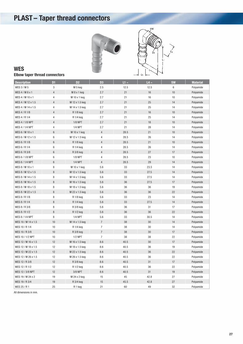
27
Description D1 D2 D3 L1 ~ L4 ~ SW Material WES 3 / M 5 3 M 5 keg 2.5 12.5 12.5 6 Polyamide
WES 4 / M 8 x 1 4 M 8 x 1 keg 2.7 21 16 10 Polyamide
WES 4 / M 10 x 1 4 M 10 x 1 keg 2.7 21 16 10 Polyamide
WES 4 / M 12 x 1.5 4 M 12 x 1.5 keg 2.7 21 25 14 Polyamide
WES 4 / M 14 x 1.5 4 M 14 x 1.5 keg 2.7 21 25 14 Polyamide
WES 4 / R 1/8 4 R 1/8 keg 2.7 21 16 10 Polyamide
WES 4 / R 1/4 4 R 1/4 keg 2.7 21 25 14 Polyamide
WES 4 / 1/8 NPT 4 1/8 NPT 2.7 21 18 10 Polyamide
WES 4 / 1/4 NPT 4 1/4 NPT 2.7 21 28 14 Polyamide
WES 6 / M 10 x 1 6 M 10 x 1 keg 4 28.5 21 10 Polyamide
WES 6 / M 12 x 1.5 6 M 12 x 1.5 keg 4 28.5 26 14 Polyamide
WES 6 / R 1/8 6 R 1/8 keg 4 28.5 21 10 Polyamide
WES 6 / R 1/4 6 R 1/4 keg 4 28.5 26 14 Polyamide
WES 6 / R 3/8 6 R 3/8 keg 4 28.5 27 17 Polyamide
WES 6 / 1/8 NPT 6 1/8 NPT 4 28.5 23 10 Polyamide
WES 6 / 1/4 NPT 6 1/4 NPT 4 28.5 29 14 Polyamide
WES 8 / M 10 x 1 8 M 10 x 1 keg 5.6 33 23.5 14 Polyamide
WES 8 / M 12 x 1.5 8 M 12 x 1.5 keg 5.6 33 27.5 14 Polyamide
WES 8 / M 14 x 1.5 8 M 14 x 1.5 keg 5.6 33 27.5 14 Polyamide
WES 8 / M 16 x 1.5 8 M 16 x 1.5 keg 5.6 36 27.5 17 Polyamide
WES 8 / M 18 x 1.5 8 M 18 x 1.5 keg 5.6 36 36 19 Polyamide
WES 8 / M 22 x 1.5 8 M 22 x 1.5 keg 5.6 36 36 22 Polyamide
WES 8 / R 1/8 8 R 1/8 keg 5.6 33 23 14 Polyamide
WES 8 / R 1/4 8 R 1/4 keg 5.6 33 27.5 14 Polyamide
WES 8 / R 3/8 8 R 3/8 keg 5.6 36 31 17 Polyamide
WES 8 / R 1/2 8 R 1/2 keg 5.6 36 36 22 Polyamide
WES 8 / 1/4 NPT 8 1/4 NPT 5.6 33 30.5 14 Polyamide
WES 10 / M 14 x 1.5 10 M 14 x 1.5 keg 7 38 30 14 Polyamide
WES 10 / R 1/4 10 R 1/4 keg 7 38 30 14 Polyamide
WES 10 / R 3/8 10 R 3/8 keg 7 38 30 17 Polyamide
WES 10 / 1/2 NPT 10 1/2 NPT 7 38 38 22 Polyamide
WES 12 / M 16 x 1.5 12 M 16 x 1.5 keg 8.6 40.5 30 17 Polyamide
WES 12 / M 18 x 1.5 12 M 18 x 1.5 keg 8.6 40.5 36 19 Polyamide
WES 12 / M 22 x 1.5 12 M 22 x 1.5 keg 8.6 40.5 36 22 Polyamide
WES 12 / M 26 x 1.5 12 M 26 x 1.5 keg 8.6 40.5 36 22 Polyamide
WES 12 / R 3/8 12 R 3/8 keg 8.6 40.5 31 17 Polyamide
WES 12 / R 1/2 12 R 1/2 keg 8.6 40.5 36 22 Polyamide
WES 12 / 3/8 NPT 12 3/8 NPT 8.6 40.5 31 19 Polyamide
WES 19 / M 24 x 2 19 M 24 x 2 keg 15 45 42.8 27 Polyamide
WES 19 / R 3/4 19 R 3/4 keg 15 45.5 42.8 27 Polyamide
WES 25 / R 1 25 R 1 keg 21 60 49 32 Polyamide
WESElbow taper thread connectors
PLAST – Taper thread connectors
All dimensions in mm.
28
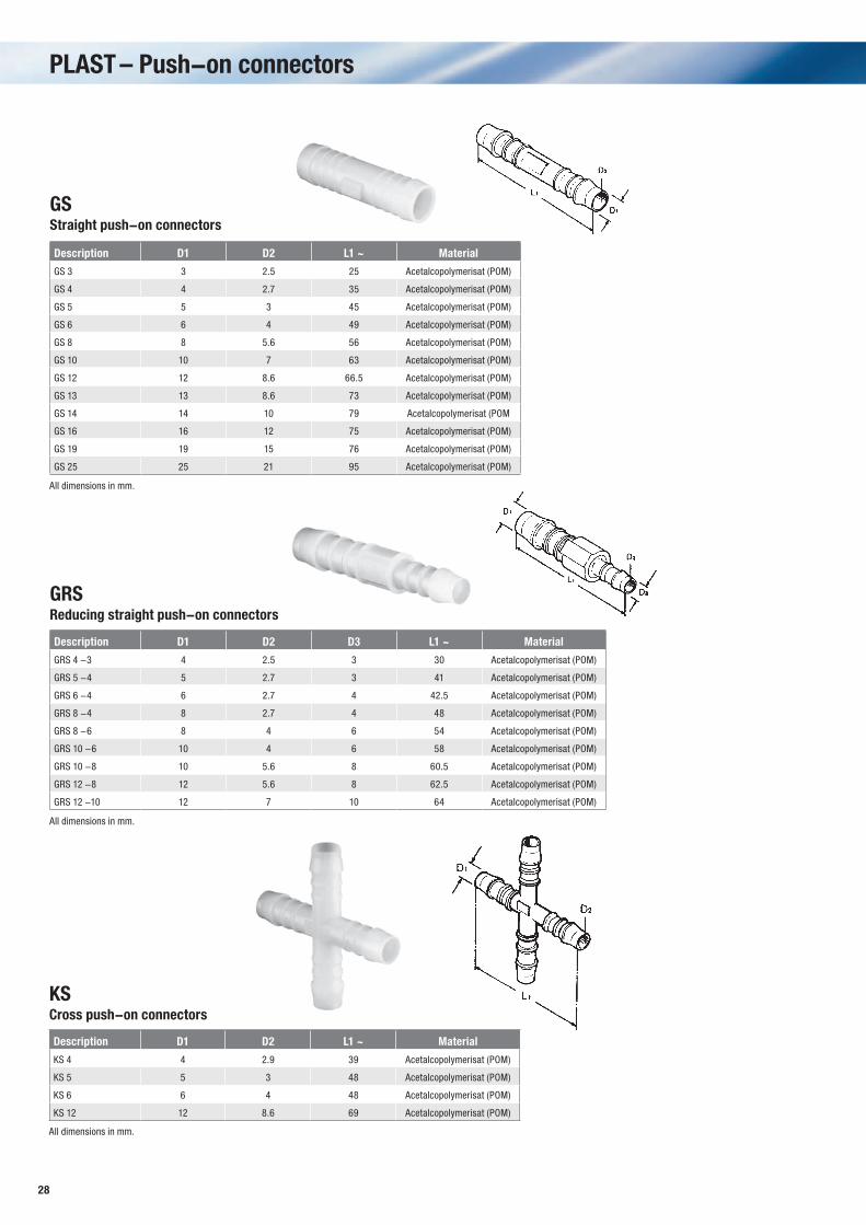
PLAST – Push-on connectors
GSStraight push-on connectors
Description D1 D2 L1 ~ Material
GS 3 3 2.5 25 Acetalcopolymerisat (POM)
GS 4 4 2.7 35 Acetalcopolymerisat (POM)
GS 5 5 3 45 Acetalcopolymerisat (POM)
GS 6 6 4 49 Acetalcopolymerisat (POM)
GS 8 8 5.6 56 Acetalcopolymerisat (POM)
GS 10 10 7 63 Acetalcopolymerisat (POM)
GS 12 12 8.6 66.5 Acetalcopolymerisat (POM)
GS 13 13 8.6 73 Acetalcopolymerisat (POM)
GS 14 14 10 79 Acetalcopolymerisat (POM
GS 16 16 12 75 Acetalcopolymerisat (POM)
GS 19 19 15 76 Acetalcopolymerisat (POM)
GS 25 25 21 95 Acetalcopolymerisat (POM)
GRSReducing straight push-on connectors
Description D1 D2 D3 L1 ~ Material
GRS 4 -3 4 2.5 3 30 Acetalcopolymerisat (POM)
GRS 5 -4 5 2.7 3 41 Acetalcopolymerisat (POM)
GRS 6 -4 6 2.7 4 42.5 Acetalcopolymerisat (POM)
GRS 8 -4 8 2.7 4 48 Acetalcopolymerisat (POM)
GRS 8 -6 8 4 6 54 Acetalcopolymerisat (POM)
GRS 10 -6 10 4 6 58 Acetalcopolymerisat (POM)
GRS 10 -8 10 5.6 8 60.5 Acetalcopolymerisat (POM)
GRS 12 -8 12 5.6 8 62.5 Acetalcopolymerisat (POM)
GRS 12 -10 12 7 10 64 Acetalcopolymerisat (POM)
All dimensions in mm.
All dimensions in mm.
KSCross push-on connectors
Description D1 D2 L1 ~ Material
KS 4 4 2.9 39 Acetalcopolymerisat (POM)
KS 5 5 3 48 Acetalcopolymerisat (POM)
KS 6 6 4 48 Acetalcopolymerisat (POM)
KS 12 12 8.6 69 Acetalcopolymerisat (POM)
All dimensions in mm.
29
PLAST – Push-on connectors
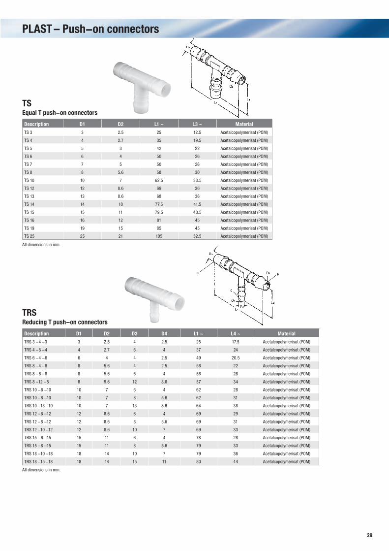
TRSReducing T push-on connectors
Description D1 D2 D3 D4 L1 ~ L4 ~ Material
TRS 3 -4 -3 3 2.5 4 2.5 25 17.5 Acetalcopolymerisat (POM)
TRS 4 -6 -4 4 2.7 6 4 37 24 Acetalcopolymerisat (POM)
TRS 6 -4 -6 6 4 4 2.5 49 20.5 Acetalcopolymerisat (POM)
TRS 8 -4 -8 8 5.6 4 2.5 56 22 Acetalcopolymerisat (POM)
TRS 8 -6 -8 8 5.6 6 4 56 28 Acetalcopolymerisat (POM)
TRS 8 -12 -8 8 5.6 12 8.6 57 34 Acetalcopolymerisat (POM)
TRS 10 -6 -10 10 7 6 4 62 28 Acetalcopolymerisat (POM)
TRS 10 -8 -10 10 7 8 5.6 62 31 Acetalcopolymerisat (POM)
TRS 10 -13 -10 10 7 13 8.6 64 38 Acetalcopolymerisat (POM)
TRS 12 -6 -12 12 8.6 6 4 69 29 Acetalcopolymerisat (POM)
TRS 12 -8 -12 12 8.6 8 5.6 69 31 Acetalcopolymerisat (POM)
TRS 12 -10 -12 12 8.6 10 7 69 33 Acetalcopolymerisat (POM)
TRS 15 -6 -15 15 11 6 4 78 28 Acetalcopolymerisat (POM)
TRS 15 -8 -15 15 11 8 5.6 79 33 Acetalcopolymerisat (POM)
TRS 18 -10 -18 18 14 10 7 79 36 Acetalcopolymerisat (POM)
TRS 18 -15 -18 18 14 15 11 80 44 Acetalcopolymerisat (POM)
All dimensions in mm.
TSEqual T push-on connectors
Description D1 D2 L1 ~ L3 ~ Material
TS 3 3 2.5 25 12.5 Acetalcopolymerisat (POM)
TS 4 4 2.7 35 19.5 Acetalcopolymerisat (POM)
TS 5 5 3 42 22 Acetalcopolymerisat (POM)
TS 6 6 4 50 26 Acetalcopolymerisat (POM)
TS 7 7 5 50 26 Acetalcopolymerisat (POM)
TS 8 8 5.6 58 30 Acetalcopolymerisat (POM)
TS 10 10 7 62.5 33.5 Acetalcopolymerisat (POM)
TS 12 12 8.6 69 36 Acetalcopolymerisat (POM)
TS 13 13 8.6 68 36 Acetalcopolymerisat (POM)
TS 14 14 10 77.5 41.5 Acetalcopolymerisat (POM)
TS 15 15 11 79.5 43.5 Acetalcopolymerisat (POM)
TS 16 16 12 81 45 Acetalcopolymerisat (POM)
TS 19 19 15 85 45 Acetalcopolymerisat (POM)
TS 25 25 21 105 52.5 Acetalcopolymerisat (POM)
All dimensions in mm.
30
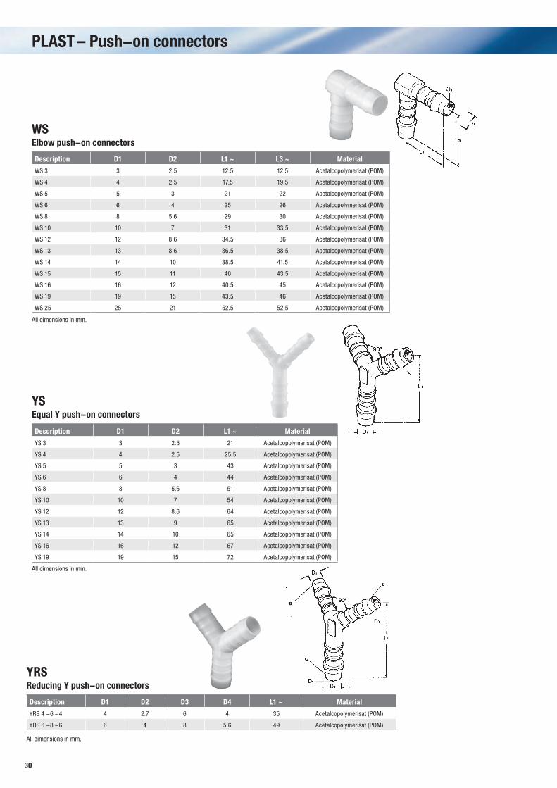
YRSReducing Y push-on connectors
Description D1 D2 D3 D4 L1 ~ Material
YRS 4 -6 -4 4 2.7 6 4 35 Acetalcopolymerisat (POM)
YRS 6 -8 -6 6 4 8 5.6 49 Acetalcopolymerisat (POM)
All dimensions in mm.
PLAST – Push-on connectors
WSElbow push-on connectors
Description D1 D2 L1 ~ L3 ~ Material
WS 3 3 2.5 12.5 12.5 Acetalcopolymerisat (POM)
WS 4 4 2.5 17.5 19.5 Acetalcopolymerisat (POM)
WS 5 5 3 21 22 Acetalcopolymerisat (POM)
WS 6 6 4 25 26 Acetalcopolymerisat (POM)
WS 8 8 5.6 29 30 Acetalcopolymerisat (POM)
WS 10 10 7 31 33.5 Acetalcopolymerisat (POM)
WS 12 12 8.6 34.5 36 Acetalcopolymerisat (POM)
WS 13 13 8.6 36.5 38.5 Acetalcopolymerisat (POM)
WS 14 14 10 38.5 41.5 Acetalcopolymerisat (POM)
WS 15 15 11 40 43.5 Acetalcopolymerisat (POM)
WS 16 16 12 40.5 45 Acetalcopolymerisat (POM)
WS 19 19 15 43.5 46 Acetalcopolymerisat (POM)
WS 25 25 21 52.5 52.5 Acetalcopolymerisat (POM)
All dimensions in mm.
YSEqual Y push-on connectors
Description D1 D2 L1 ~ Material
YS 3 3 2.5 21 Acetalcopolymerisat (POM)
YS 4 4 2.5 25.5 Acetalcopolymerisat (POM)
YS 5 5 3 43 Acetalcopolymerisat (POM)
YS 6 6 4 44 Acetalcopolymerisat (POM)
YS 8 8 5.6 51 Acetalcopolymerisat (POM)
YS 10 10 7 54 Acetalcopolymerisat (POM)
YS 12 12 8.6 64 Acetalcopolymerisat (POM)
YS 13 13 9 65 Acetalcopolymerisat (POM)
YS 14 14 10 65 Acetalcopolymerisat (POM)
YS 16 16 12 67 Acetalcopolymerisat (POM)
YS 19 19 15 72 Acetalcopolymerisat (POM)
All dimensions in mm.
31
L1
D2 D1
L1
D2
D1
L3
L1
D2L3
D1
L1
D2
D1
L1
PLAST – Push-on connectors
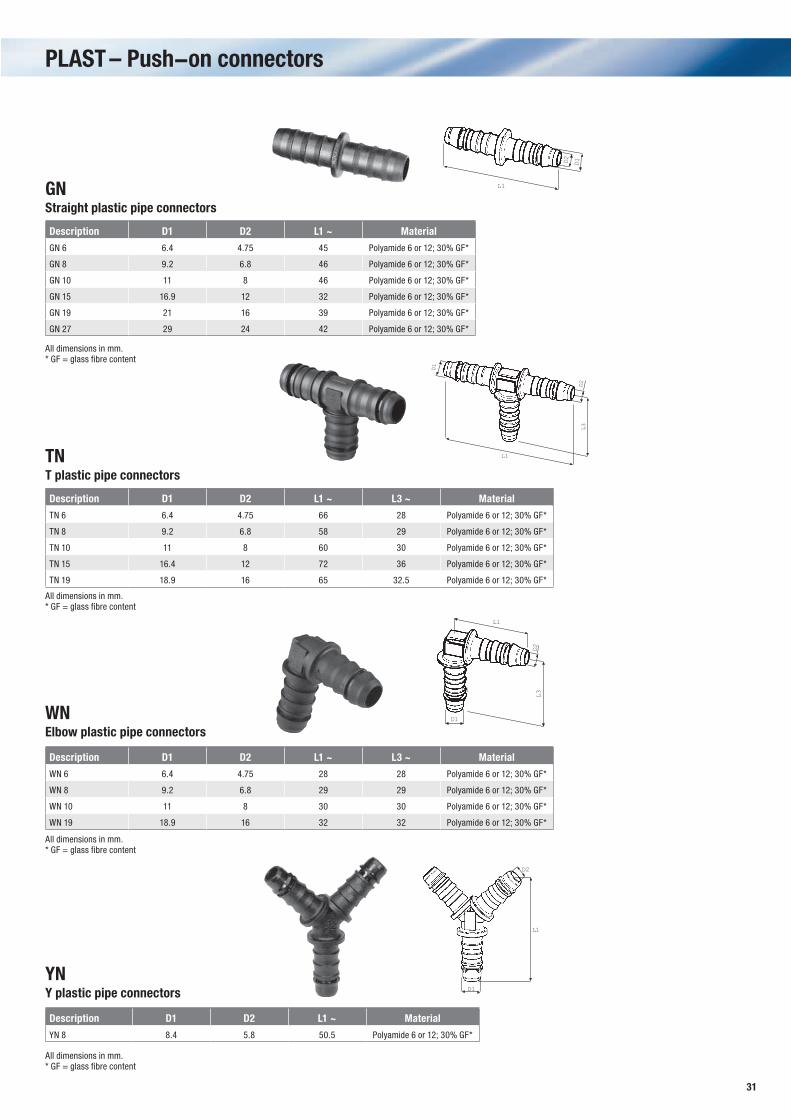
GNStraight plastic pipe connectors
Description D1 D2 L1 ~ Material
GN 6 6.4 4.75 45 Polyamide 6 or 12; 30% GF*
GN 8 9.2 6.8 46 Polyamide 6 or 12; 30% GF*
GN 10 11 8 46 Polyamide 6 or 12; 30% GF*
GN 15 16.9 12 32 Polyamide 6 or 12; 30% GF*
GN 19 21 16 39 Polyamide 6 or 12; 30% GF*
GN 27 29 24 42 Polyamide 6 or 12; 30% GF*
All dimensions in mm.* GF = glass fibre content
TNT plastic pipe connectors
Description D1 D2 L1 ~ L3 ~ Material
TN 6 6.4 4.75 66 28 Polyamide 6 or 12; 30% GF*
TN 8 9.2 6.8 58 29 Polyamide 6 or 12; 30% GF*
TN 10 11 8 60 30 Polyamide 6 or 12; 30% GF*
TN 15 16.4 12 72 36 Polyamide 6 or 12; 30% GF*
TN 19 18.9 16 65 32.5 Polyamide 6 or 12; 30% GF*
All dimensions in mm.* GF = glass fibre content
WNElbow plastic pipe connectors
Description D1 D2 L1 ~ L3 ~ Material
WN 6 6.4 4.75 28 28 Polyamide 6 or 12; 30% GF*
WN 8 9.2 6.8 29 29 Polyamide 6 or 12; 30% GF*
WN 10 11 8 30 30 Polyamide 6 or 12; 30% GF*
WN 19 18.9 16 32 32 Polyamide 6 or 12; 30% GF*
YNY plastic pipe connectors
Description D1 D2 L1 ~ Material
YN 8 8.4 5.8 50.5 Polyamide 6 or 12; 30% GF*
All dimensions in mm.* GF = glass fibre content
All dimensions in mm.* GF = glass fibre content

32
Quality in products and servicesAs a customer of ABA premium hose and pipe clamping and connecting products, you will always enjoy:
– First-class products produced in plants certified to TS 16949:2000. The best steel qualities enable stable processes and provide a high and even product quality.
– Continuous improvement to always exceed the demands of our SS2298 standard. This assures you of products with a high break torque combined with a high clamp-ing force around the hose. ABA Safeseal Technology – our guarantee to you.
– The ABA Original product line. Clamps without welded or riveted housings. In-stead, just one purpose-made tube pressed to its final shape in a precision process. All bands have embossed threads
The Customer in focus
that allow a flat band underside to tightly fit against the hose wall.
– Prompt and secure delivery of all our products in this catalogue. Essential in to-day’s industrial sector.
– Technical advice for a variety of applica-tions such as drainage waste water pipes, freshwater pipes, fuel lines, water and air hoses, etc. We also provide you with test data using your own tubes or hoses – free of charge!
– Our products are produced in plants certi-fied to ISO14001 and made entirely with recyclable materials.
– Packaging with a solid design made to satisfy different customer needs.
– Highly-appreciated merchandisers used all over the world as efficient sales tools.
– A wide variety of sales promotion materi-als and product training for our Distribu-tors.
NORMA Sweden AB’s factory in Anderstorp
33
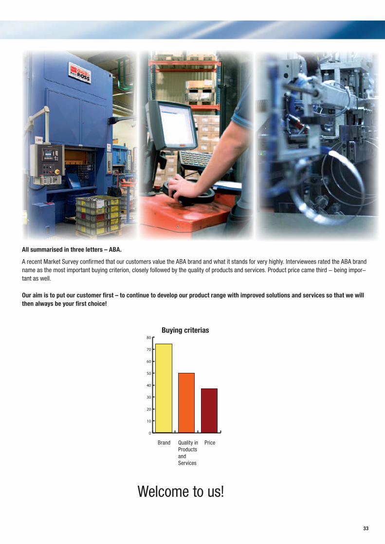
All summarised in three letters – ABA.
A recent Market Survey confirmed that our customers value the ABA brand and what it stands for very highly. Interviewees rated the ABA brand name as the most important buying criterion, closely followed by the quality of products and services. Product price came third - being impor-tant as well.
Our aim is to put our customer first – to continue to develop our product range with improved solutions and services so that we will then always be your first choice!
Welcome to us!
0
10
20
30
40
50
60
70
80
Buying criterias
Brand Quality in Products and Services
Price
34
Notes
35
Notes

ABA - a NORMA Group brand
1-2A
-6-
2010
0623
-SE
NORMA Sweden AB
Box 100 Visirgatan 1334 22 Anderstorp
Tel.: +46 371 58 88 00 Fax.: +46 371 58 88 01
www.normagroup.com