SAFECAP SC4€¦ · clearly distinguishable plug connections with connector cables in black (A) and...
16
SAFECAP SC4 SAFECAP SC4 22 The SC4 is an intelligent system consisting of SCA4 + SCB4 as well as the MasterCAP MCR-225 relay. The high level of safety is also enforced by two SENSORswitches, which need to be connected to each other with a functional safety line, which, in turn, ensures the use of two different safeCAP A + B sensors within one two-hand control. The concept is supported by two clearly distinguishable plug connections with connector cables in black (A) and yellow jacket colours (B) for the connection with the two-hand safety relay MasterCAP MCR-225. This only has a housing width of 22.5 mm and is to be attached to a standard rail. The safeCAP corresponds to DIN EN 574 as a two-hand control type III C. The safety-related features are designed with category 4 and PL e according to DIN EN ISO 13849-1. Der SC4 ist ein intelligentes System bestehend aus SCA4 + SCB4 sowie dem MasterCAP MCR-225 Relais. Den hohen Sicherheitsgrad gewährleistet auch die Besonderheit, dass die beiden SENSORtaster untereinander mit einer Funktions-Sicherheitsleitung verbunden werden müssen, die den Einsatz der zwei unterschiedlichen Sensoren safeCAP A+B innerhalb einer Zweihandsteuerung sicherstellt. Unterstützt wird das Konzept durch zwei verwechslungssichere Steckverbindungen mit Anschlusskabel in schwarzer (A) und gel- ber Mantelfarbe (B), für die Verbindung mit dem Zweihand-Sicher- heitsrelais MasterCAP MCR-225. Dies hat nur eine Gehäusebreite von 22,5 mm und ist auf einer Normschiene zu befestigen. Der safeCAP entspricht als Zweihandschaltung Typ III C nach DIN EN 574. Die sicherheitsrelevanten Funktionen werden mit Kategorie 4 und PL e nach DIN EN ISO 13849-1 ausgeführt.
Transcript of SAFECAP SC4€¦ · clearly distinguishable plug connections with connector cables in black (A) and...

SAFECAP SC4
SAFECAP SC4
22
The SC4 is an intelligent system consisting of SCA4 + SCB4 as well as the MasterCAP MCR-225 relay. The high level of safety is also enforced by two SENSORswitches, which need to be connected to each other with a functional safety line, which, in turn, ensures the use of two different safeCAP A + B sensors within one two-hand control. The concept is supported by two clearly distinguishable plug connections with connector cables in black (A) and yellow jacket colours (B) for the connection with the two-hand safety relay MasterCAP MCR-225. This only has a housing width of 22.5 mm and is to be attached to a standard rail. The safeCAP corresponds to DIN EN 574 as a two-hand control type III C. The safety-related features are designed with category 4 and PL e according to DIN EN ISO 13849-1.
Der SC4 ist ein intelligentes System bestehend ausSCA4 + SCB4 sowie dem MasterCAP MCR-225 Relais.Den hohen Sicherheitsgrad gewährleistet auch die Besonderheit,dass die beiden SENSORtaster untereinander mit einerFunktions-Sicherheitsleitung verbunden werden müssen, die denEinsatz der zwei unterschiedlichen Sensoren safeCAP A+Binnerhalb einer Zweihandsteuerung sicherstellt. Unterstützt wird das Konzept durch zwei verwechslungssichere Steckverbindungen mit Anschlusskabel in schwarzer (A) und gel-ber Mantelfarbe (B), für die Verbindung mit dem Zweihand-Sicher-heitsrelais MasterCAP MCR-225. Dies hat nur eine Gehäusebreite von 22,5 mm und ist auf einer Normschiene zu befestigen.Der safeCAP entspricht als Zweihandschaltung Typ III C nachDIN EN 574. Die sicherheitsrelevanten Funktionen werden mitKategorie 4 und PL e nach DIN EN ISO 13849-1 ausgeführt.

100% wasser- und öldichtSchutzart IP69K, komplett mit Gießharz vergossen100% water and oilproofProtection class IP69K, fully sealed in casting resin
Extrem lange LebensdauerÜber 100 Millionen SchaltspieleExtremely long service life Over 100 million switching cycles
Schlagfest - robustSchutzgrad IK08, kann durch Feuerzeugfl ammen und Schläge auf die Tastfl äche nicht zerstört werdenImpact-resistant - robustProtection rating IK08, cannot be destroyed by lighter fl ames and blows to the switch surface
1700g
FremdkörperkontrolleErkennt störende GegenständeForeign object checkRecognises obstructions
VerschmutzungskontrolleErkennt SchmutzContamination controlRecognises contamination
Touch sensorHoher Bedienkomfort, kein Kraftaufwand notwendig, keine Überbeanspruchung der HandgelenkeTouch sensorMaximum ease of use, effortless, no strain on wrists
23

SAFECAP SC4 TECHNISCHE DATEN
SAFECAP SC4 TECHNICAL DATA
AN / ON
AUS / OFF
AN / ONBLINKEND / FLASHING
AN / ON
AUS / OFF
ÜberwachungsanzeigeControl display
8 grüne LEDs leuchten, wenn Spannung anliegt und keine Berührung stattfi ndet
8 rote LEDs leuchten, 8 grüne LED gehen aus, wenn Tastfl äche berührt wird
8 grüne LEDs leuchten, 8 rote LED blinken. safeCAP lässt sich nicht bedienen, wenn:- die Tastgeschwindigkeit zu gering ist
(Fehlbedienung)- dieTastfl äche verschmutzt bzw. feucht ist- störende Gegenstände auf der Tastfl äche liegen
8 green LEDs light up when voltage is present and there is no contact
8 red LEDs light up, 8 green LEDs extinguish when the switch surface is touched
8 green LEDs light up, 8 red LEDs fl ash. safeCAP cannot be operated if:- the keying speed is too low (operating error)- the surface of the switch is contaminated or damp- obstructions are present on the surface of the switch
Betrieb
Betätigung
Störung
Operation
Triggering
Error
Bohrbild SCA4 + SCB4Hole pattern SCA4 + SCB4
Alle Maße in mm All dimensions in mm
24
Anschlussbelegung Connection diagram
Funktions-Sicherheitsleitung 1m
+
S11 S22S11 S12S12 S21A1 A2S22 S21
-
LKW-SCA-2 (2m)LKW-SCA-5 (5m)
LKW-SCB-2LKW-SCB-5 (
AA BB
Bei den Ausgangsrelais vonsafecap A+B handelt essich um elektronische
PhotoMOS-Relais
Hinweis:
SCA4 SCB4
Zweihand-Sicherheitsrelais mastercap MCR-225Two hand safety control mastercap MCR-225
Functional line Safety cable 1m
Note: The safeCAP output relays A+B
are electronic PhotoMOS relays
Bla
ck
NO 24 V 0 VNONC
(2 m) (2 m)(5 m)
Kategorie 4 Typ III CCategory 4 Type III C
(5 m)
NC
Gre
y
Bro
wn
Blu
e
Whi
te
Yello
w

25
MaßzeichnungDrawing
SCA4SCA4
SCB4 SCB4
Alle Maße in mm All dimensions in mm
Technische Daten Technical data
Bemessungsbetriebsspannung Rated operating voltage 24 V DC
Leistungsaufnahme Power consumption ca. 1,5 W
Schaltfrequenz Switching frequency 1 Hz
Temperaturbereich Temperature range 0…+55 °C
Schutzart Protection class IP69K, Stecker IP67 IP69K, Connector IP67

SICHERHEITSRELAIS MCR-225
SAFETY RELAIS MCR-225
HinweisSind die beiden SC4 beim Einschalten der Betriebsspannung bereits betätigt (nach einem Spannungsausfall), sprechen die Ausgangskontakte nicht an. Die Anschlussklemme S22 (-) dient auch als Bezugspunkt zur Prüfung der Steuerspannung.
Geräteanzeigen LEDsLED ON leuchtet bei anliegender BetriebsspannungLED K1 leuchtet bei bestromtem Relais K1LED K2 leuchtet bei bestromtem Relais K2
NoteIf both SC4 are touched while switching on the operating voltage (e.g. after voltage failure) the output contacts do not energize.The terminal S22 also serves as reference point for checking the control voltage.
IndicationLED ON on, when operating voltage appliedLED K1 on, when relay K1 activeLED K2 on, when relay K2 active
• Eingänge für SCA4 + SCB4
• Ausgang: 2 Schließer und 1 Öffner
• Über Rückführkreis Y1 - Y2 Überwachung externer Schützezur Kontaktvervielfältigung und -verstärkung
• Überspannungs- und kurzschlussfest
• Inputs SCA4 + SCB4
• Output: 2 makers and 1 breaker
• Monitoring of external contactors for contact multiplication and reinforcement via feedback loop Y1 - Y2
• Over-current and short-circuit proof
26

FunktionsdiagrammFunctional diagram
Anschlußübersicht Connection diagram
MCR-225
+24V
0V
Rückführ-kreis
A
B
Safecap
Safecap
RückführkreisFeedback circuit
27
SCA4
SCB4
Blockschaltbild Block diagram
MaßzeichnungDrawing
ON
Überspannungs- und KurzschlussschutzOvervoltage andShort circuit fuse
ÜberwachungslogikMonitoring logic
Alle Maße in mm All dimensions in mm
K3
K4
K3Leistungs-kreis
MCR-225
+24V
0V
K3
K3
K4
K4
3123
2414 32
Feedbackcircuit
Rückführkreis
RückführkreisFeedback circuit
LeistungskreisPower circuit
K3
K4
Zweihandsteuerung mit Kontaktvervielfältigung überexterne zwangsgeführte Schütze. Beim Schalteninduktiver Lasten sind Funkenlöschglieder vorzusehen.
Two-hand control with contact reinforcement viaexternal positively driven contactors. When switchinginductive loads spark absorbers are recommended.
Anschlußübersicht mit KontaktvervielfältigungConnection diagram with contact multiplication

TECHNISCHE DATEN
TECHNICAL DATA
EMV Prüfungen EMC tests
Leitungsgeführte Störgrößen Conducted disturbance levels EN 55011 0,15…30 MHz
Gestrahlte Störgrößen (elektrisches Feld) Radiated disturbance levels (electrical fi eld) EN 55011 30…1000 MHz
Entladung statischer Elektrizität (ESD) Electrostatic discharge (ESD)
EN 61000-4-2EN 61000-4-2
Kontakt 6 kV Contact 6 kVLuft 8 kV Air 8 kV
Hochfrequente elektromagnetische Felder High-frequency electromagnetic fi elds EN 61000-4-3 80…2700 MHz bis zu 20 V/m
80…2700 MHz up to 20 V/m
Schnelle transiente elektrische Störgrößen (Burst)Rapid transient electrical disturbance levels (burst)
EN 61000-4-4EN 61000-4-4
Netzwerk 3 kV Network 3 kVKoppelzange 2 kV Coupling clamp 2 kV
Stoßspannungen (Surge) Voltage impulses (surges)
EN 61000-4-5EN 61000-4-5
Symmetrisch 1 kV Symmetrical 1 kVUnsymmetrisch 2 kV Unsymmetrcal 2 kV
Leitungsgeführte Störgrößen Conducted disturbance levels EN 61000-4-6 0,15…80 MHz / 10 V
Magnetfelder mit energietechnischen Frequenzen Magnetic fi elds with energy frequencies EN 61000-4-8 50 Hz / 60 Hz / 30 A/m
Leitungsgeführte, asymmetrische StörgrößenConducted, asymmetric disturbance levels EN 61000-4-16 1,5…150 kHz bis zu 10 V 1,5…150 kHz up to 10 V
Spannungseinbrüche Voltage drops
EN 61000-4-11 EN 61000-4-29 60% / 10 ms
Kurzzeitunterbrechungen Short interruptions
EN 61000-4-11 EN 61000-4-29 20 ms
Technische Daten Technical data
Bemessungsbetriebsspannung Rated operating voltage 24 V DC
Leistungsaufnahme Power consumption ca. 2,3 W Approx. 2,3 W
Anzahl der Sicherheitsstrompfade Number of safety current paths 2 Schließer, 1 Öffner 2 NO, 1 NC
Kontaktabsicherung Contact fuse 6 AgL, C8 A (Sicherheitsautomat) 6 AgL, C8 A (automatic circuit breaker)
Schaltvermögen nach AC 15 Switching capacity as per AC 153 A / 230 V für den Schließer 3 A / 230 V for NO 2 A / 230 V für den Öffner 2 A / 230 V for NC
Temperaturbereich Temperature range 0…+55 °C
Schutzart Protection class Gehäuse IP40, Klemmbereich IP20 Housing IP 40, clamping area IP 20
Gewicht Weight 200 g
Typ Type III C
28

Mechanische Prüfungen Mechanical tests
Schwingprüfung Vibration test 10…55 Hz
Schockprüfung Shock test 30 g
Schlagprüfung Impact test GS-ET-20
Glühdrahtprüfung DIN EN 60695-2-11Glow wire test DIN EN 60695-2-11 850 °C
Luft- und Kriechstrecken DIN EN 60947-5-1Air and creepage paths DIN EN 60947-5-1
Überspannungskategorie III / Verschmutzungsgrad 2Overvoltage category III / degree of contamination 2
Nachweis der Stoßspannungsfestigkeit Verifi cation of impulse withstand voltage
Alle miteinander verbundenen Anschlüsse des Betriebsspannungskreises gegen das leitfähig umhüllte Gehäuse All operating voltage circuit connections that are connected to each other against the conductive, encased housing 0,9 kV
Alle miteinander verbundenen Anschlüsse der sicherheitsrelevanten Kontaktstrompfade gegen das leitfähig umhüllte GehäuseAll safety-related contact current path connections that are connected to each against the conductive, encased housing 4,8 kV
Alle miteinander verbundenen Anschlüsse des Steuerstromkreises gegen das leitfähig umhüllte GehäuseAll control current circuit connections that are connected to each other against the conductive, encased housing 0,9 kV
Betriebsspannungskreis gegen die sicherheitsrelevanten KontaktstrompfadeOperating voltage circuit against the safety-related contact current paths 4,8 kV
Steuerstromkreis gegen die sicherheitsrelevanten KontaktstrompfadeControl current circuit against the safety-related contact current paths 4,8 kV
Zwischen den sicherheitsrelevanten KontaktstrompfadenBetween the safety-related contact current paths 4,8 kV
Nachweis der betriebsfrequenten Spannungsfestigkeit Verifi cation of the power frequency withstand voltage
Alle miteinander verbundenen Anschlüsse des Betriebsspannungskreises gegen das leitfähig umhüllte Gehäuse All operating voltage circuit connections that are connected to each other against the conductive, encased housing 1,5 kV
Alle miteinander verbundenen Anschlüsse der sicherheitsrelevanten Kontaktstrompfade gegen das leitfähig umhüllte GehäuseAll safety-related contact current path connections that are connected to each against the conductive, encased housing 2,25 kV
Alle miteinander verbundenen Anschlüsse des Steuerstromkreises gegen das leitfähig umhüllte GehäuseAll control current circuit connections that are connected to each other against the conductive, encased housing 1,5 kV
Betriebsspannungskreis gegen die sicherheitsrelevanten KontaktstrompfadeOperating voltage circuit against the safety-related contact current paths 1,5 kV
Steuerstromkreis gegen die sicherheitsrelevanten KontaktstrompfadeControl current circuit against the safety-related contact current paths 1,5 kV
Zwischen den sicherheitsrelevanten KontaktstrompfadenBetween the safety-related contact current paths 1,5 kV
29

30

16/17
SC4 SETS
SC4 SETS
31
SC4 BASIC
SC4 BASIC
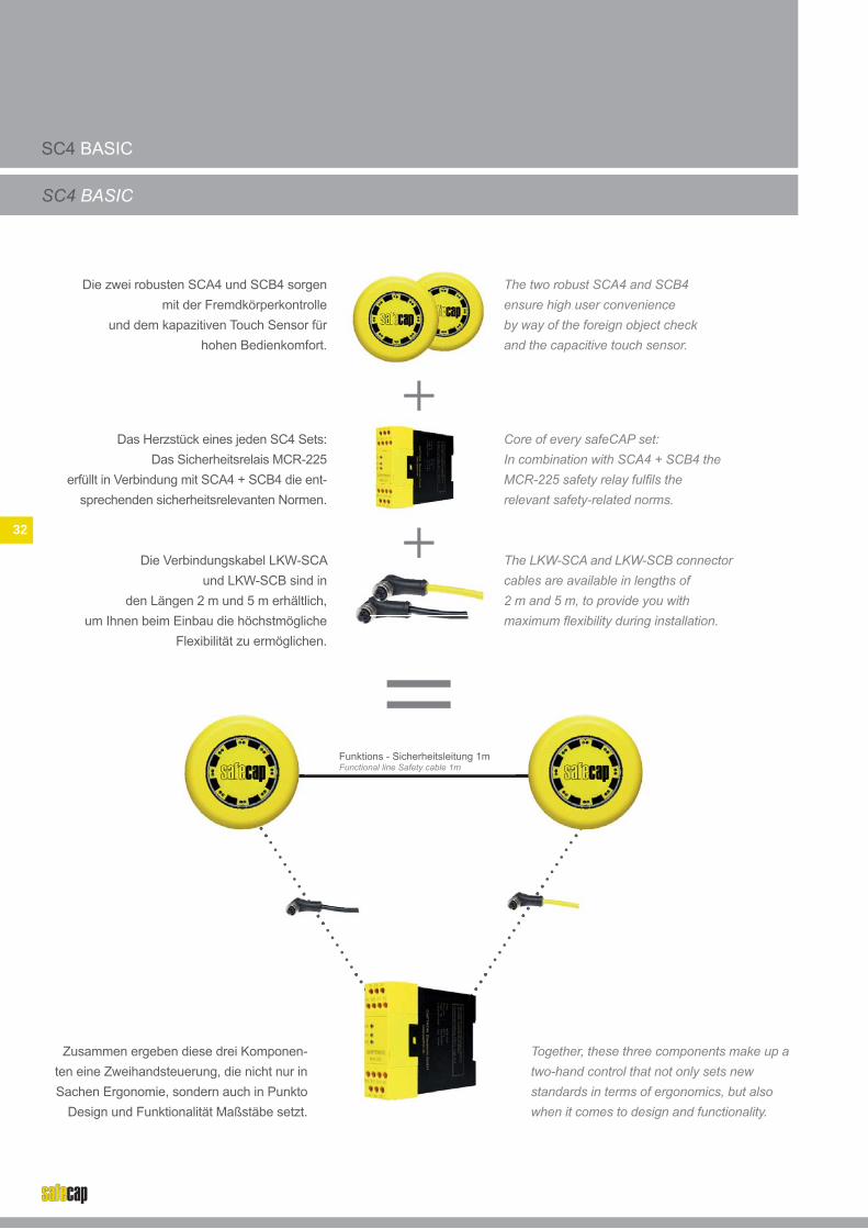
Die zwei robusten SCA4 und SCB4 sorgen mit der Fremdkörperkontrolle
und dem kapazitiven Touch Sensor für hohen Bedienkomfort.
Zusammen ergeben diese drei Komponen-ten eine Zweihandsteuerung, die nicht nur in Sachen Ergonomie, sondern auch in Punkto
Design und Funktionalität Maßstäbe setzt.
Das Herzstück eines jeden SC4 Sets:Das Sicherheitsrelais MCR-225
erfüllt in Verbindung mit SCA4 + SCB4 die ent-sprechenden sicherheitsrelevanten Normen.
Die Verbindungskabel LKW-SCA und LKW-SCB sind in
den Längen 2 m und 5 m erhältlich, um Ihnen beim Einbau die höchstmögliche
Flexibilität zu ermöglichen.
The two robust SCA4 and SCB4ensure high user convenience by way of the foreign object check and the capacitive touch sensor.
Together, these three components make up a two-hand control that not only sets new standards in terms of ergonomics, but also when it comes to design and functionality.
Core of every safeCAP set:In combination with SCA4 + SCB4 the MCR-225 safety relay fulfi ls the relevant safety-related norms.
The LKW-SCA and LKW-SCB connector cables are available in lengths of 2 m and 5 m, to provide you withmaximum fl exibility during installation.
Thecab2 m
32
Funktions - Sicherheitsleitung 1mFunctional line Safety cable 1m

SC4 PROTECT
SC4 PROTECT
Verbindungskabel LKW-SCA und LKW-SCB.
Die Besonderheit des SC4 Protect Set liegt in den beiden Protectoren SCP-4, die zwischen Taster und Arbeitsoberfl äche montiert werden und zu-
sätzlichen Schutz vor Fremdeinwirkungen bieten.
Connector cables LKW-SCA and LKW-SCB.
The SC4 Protect set is characterised by the two protectors SCP-4 that are mounted between the switch and the work desk, providing additional protection against outside infl uences.
Das SC4 Protect Set beinhaltet standardmäßig Protectoren für die Tischmontage.
Eine detaillierte Übersicht des erhältlichen Zubehörs fi nden Sie auf Seite 37-39.
The SC4 Protect Set contains protectors for table mounting. You can fi nd a detailed overview of available accessories on page 37-39.
Die Basis des SC4 Protect Set besteht, wie jedes andere SC4 Set auch, aus
SCA4 + SCB4 und dem Sicherheitsrelais.
The SC4 Protect set, like any other safeCAP set, is based on SCA4 + SCB4 and the safety relay.
33
Funktions - Sicherheitsleitung 1mFunctional line Safety cable 1m

SC4 COMPLETE
SC4 COMPLETE
Verbindungskabel LKW-SCA und LKW-SCB
SCA4 + SCB4 und MCR-225
Connector cables LKW-SCA and LKW-SCB
SCA4 + SCB4 and MCR-225
C
Unser Rundum-Sorglos-Paket: Das SC4 Complete erfüllt durch seine
normgerechte Konstruktion alle Anforderungen zur Sicherheit von Zweihandsteuerungen
nach DIN EN 574
Our all-round carefree package: The SC4 Complete fulfi ls all safety requirements for two-hand controls, thanks to its norm-compliant construction, according to DIN EN 574
Das SC4 Bedienpult ist in der Materialausführung Kunststoff (Option: Aluminium)
erhältlich. Die Standardversion aus Kunststoff sowie die Option als Aluminium erfüllen die
Sicherheitsanforderung für Zweihandsteuerungen.
The SC4 operator control is available in material plastic (option: aluminum). The standard version made of plastic as well as the option made of aluminum comply with the safety requirements for two-hand controls.
34

Bei Konstruktion, Montage und Inbetriebnahme von safeCAP sind die Forderungen der EN 574 unbedingt einzuhalten!
It is absolutely essential that the regulations stated in EN 574 are complied with for assemblies involving the installation and commissioning of safeCAP!
Übersicht aller VariantenOverview of all variants
KriterienCriteria
VarianteVariant
SC4 Basic SC4 Protect SC4 Complete
Vermeiden von Umgehen mit einer HandAbstand ≥ 260 mm *1
Avoid use of one hand at a distance of ≥ 260 mm *1
Vermeiden von Umgehen mit Hand und Ellbogen desselben Arms ≥ 550 mm *2
Avoid use of the hand and elbow of the same arm at ≥ 550 mm *2
Vermeiden von Umgehen mit Unterarm(en) oder dem (den) Ellbogen *3
Avoid use of the forearm(s) or the elbow(s) *3
Vermeiden von Umgehen mit einer Hand und jedem anderen Teil des Körpers (z.B. Knie, Hüfte) ≥ 1100 mm *4
Avoid use of one hand and any other part of the body (e.g. knee, hip) at ≥ 1100 mm *4
Vermeiden von Umgehen durch Blockiereneines Stellteils *5
Avoid use by blocking one of the control devices *5
Erfüllt das Kriterium bereits werksseitigFulfi ls the criterion ex-factory
Erfüllt das Kriterium nur durch zusätzliche anwenderseitige normgerechte MaßnahmenOnly fulfi ls the criterion through additional norm-compliant measures on the user side
*1 Es müssen Maßnahmen zur Vermeidung des Umgehens mit einer Hand getroffen werden. Z.B. räumliche Trennung der Stellteile (lichtes Maß) von wenigstens 260 mm.
*2 Es müssen Maßnahmen zur Vermeidung des Umgehens durch eine Hand und den Ellbogen desselben Arms getroffen werden. Z.B. Trennung der Stellteile von wenigstens 550 mm (lichtes Maß). Aus ergonomischen Gründen sollte dieser Abstand nicht größer als 600 mm sein; oder Überdeckungen, die so gestaltet sind, dass die Stellteile nicht mit dem Ellbogen betätigt werden können.
*3 Es müssen Maßnahmen zur Vermeidung des Umgehens mit Unterarm(en) und/oder Ellbogen getroffen werden, wenn der Abstand der Hände zur Gefahrstelle durch das Benutzen der (des) Unterarme(s) und/oder der (des) Ellbogen(s) kleiner ist als der erforderliche Sicherheitsabstand. Eine geeignete Maßnahme ist die Verwendung von Abdeckungen und/oder Kragen, die so gestaltet sind, dass die Stellteile mit dem (den) Unterarm(en) und/oder Ellbogen betätigt werden können.
*4 Es müssen Maßnahmen zur Vermeidung des Umgehens durch das Benutzen anderer Teile des Körpers in Verbindung mit einer Hand getroffen werden. Z.B. Anordnung der Stellteile auf einer horizontalen oder nahezu horizontalen Fläche mit wenigstens einem Abstand von 1100 mm über dem Boden oder der Zugangsebene. Das soll die Betätigung mit der Hüfte verhindern;oder Abdeckungen und/oder Trennwände, die so gestaltet sind, dass die Stellteile weder mit einer einzigen Hand noch durch jedes andere Körperteil betätigt werden können.
*5 Es müssen Maßnahmen zur Vermeidung des Umgehens durch Blockieren eines Stellteils getroffen werden. Z.B. um den ersten Anlauf mittels einer einzigen Hand zu verhindern, ist es erforderlich, der Zweihandschaltung die Eigenschaften für synchrone Betätigung zu verleihen.
*1 Measures for avoiding use of one hand must be implemented, e.g. spatial separation of the control devices (clear measurement) of at least 260 mm.
*2 Measures for avoiding use of one hand and the elbow of the same arm must be implemented e.g. separation of the control devices of at least 550 mm(clear measurement). For ergonomic reasons, this distance should not be greater than 600 mm; or covers that are designed in such a manner that the control devices cannot be activated by the elbow.
*3 Measures for avoiding use of the forearm(s) and/or elbows must be implemented if the distance of the hands from the danger point is smaller than the required safety distance when using the forearm(s) or the elbow(s). A suitable measure is the use of covers and/or collars that are designed in such a manner that the control devices cannot be activated by the forearm(s) and/or elbow(s).
*4 Measures for avoiding the use of other body parts in conjunction with one hand must be implemented e.g. arranging the control devices on a horizontal or almost horizontal surface with a minimum distance of 1100 mm above the ground or access level. This should avoid activation by means of the hip; or covers and/or separating walls that are designed in such a manner that the control devices can neither be activated using only one hand nor using any other body part.
*5 Measures for avoiding bypassing by means of blocking a control device must be implemented, e.g. to avoid fi rst start-up using only one hand, the two-hand control must be fi tted with properties for synchronous activation.
35

ÜBERSICHT SAFECAP SC4 PRODUKTE
OVERVIEW SAFECAP SC4 PRODUCTS
36
AbbildungImage
BestellbezeichnungOrder Code
BeschreibungDescription
SCA4-185Z-S SCA4
SCB4-185Z-S SCB4
MCR-225 Sicherheitsrelais MasterCAPSafety Relais MasterCAP
SC4-Basic-2
Set: • SCA4-185Z-S • SCB4-185Z-S • MCR-225 • LKW-SCA-2 • LKW-SCB-2
SC4-Basic-5
Set: • SCA4-185Z-S • SCB4-185Z-S • MCR-225 • LKW-SCA-5 • LKW-SCB-5
SC4-Protect-2
Set: • SCA4-185Z-S • SCB4-185Z-S• MCR-225• LKW-SCA-2• LKW-SCB-2• 2x SCP-4
SC4-Protect-5
Set: • SCA4-185Z-S• SCB4-185Z-S• MCR-225• LKW-SCA-5• LKW-SCB-5• 2x SCP-4
SC4-Complete-2
Set: • SCA4-185Z-S• SCB4-185Z-S• MCR-225• LKW-SCA-2• LKW-SCB-2• SC4-Pult-1
SC4-Complete-5
Set: • SCA4-185Z-S• SCB4-185Z-S• MCR-225• LKW-SCA-5• LKW-SCB-5• SC4-Pult-1
(2 m Kabel 2 m cable)
(2 m Kabel 2 m cable)
(2 m Kabel 2 m cable)
(5 m Kabel 5 m cable)
(5 m Kabel 5 m cable)
(5 m Kabel 5 m cable)

ÜBERSICHT SAFECAP SC4 ZUBEHÖR
OVERVIEW SAFECAP SC4 ACCESSORY
37
AbbildungImage
Bestellbe-zeichnungOrder code
BeschreibungDescription
MaßzeichnungDrawing
SC4-Pult-1 Glasfaserverstärkter KunststoffGlass fi bre reinforced plastic
SC4-Pult-2 Aluminium-DruckgussgehäuseDie-cast aluminium housing