Safe communication between remote locations with modular system HImatrix F
21
Safe communication between remote locations with modular system HIMatrix F Traffic
-
Upload
minka-grdesic -
Category
Technology
-
view
73 -
download
0
Transcript of Safe communication between remote locations with modular system HImatrix F
Safe communication between remote locations with modular system HIMatrix F
Tra
ffic

EDITORIAL TEAM
NOTE
AUTHOR - Rok ModicREVISION- Stanislav ErzarAPPROVAL - Stanislav Erzar
All information contained in or disclosed by this document is confidential. By accepting this material the recipient agrees that this material and the information contained therein will be held in confidence and will not be reproduced, disclosed, or used in whole or in part except for purposes of this document.
This document has 20 pages including cover page and table of contents.
Copyrights Iskra Sistemi, Stegne 21, SI-1000 Ljubljana, SLOVENIA. All rights reserved. No part of this publication may be reproduced in any form or by any means without the written permission of Iskra Sistemi.
SHORT DESCRIPTIONModular system HIMatrix F enables safe transfer of digital signals via safeethernet protocol.
Safe communication between remote locations with modular system HIMatrix F I 02
Safe communication between remote locations with modular system HIMatrix F I 03
CONTENT
SHORT
DESCRIPTION.............................................................................................................................
1 System desctiption ...................................................................................................................
2 List of HIMatrix F units .............................................................................................................
2.1 HIMatrix F30 03 ....................................................................................................................
2.2 HIMatrix F1 DI 16 01 .............................................................................................................
2.3 HIMatrix F2 DO 16 02 ...........................................................................................................
2.4 HIMatrix F3 DIO 8/8 ..............................................................................................................
2.5 F3 DIO 20/8 02 .....................................................................................................................
3 Use of different transsmision media ........................................................................................
3.1 Copper (twisted pair, two pairs) ............................................................................................
3.2 Optic fibre .............................................................................................................................
3.3 WLAN ...................................................................................................................................
4 Software ..................................................................................................................................
5 Example ..................................................................................................................................
FIGURES
Figure 1: HIMatrix F30 03 ............................................................................................................
Figure 2: HIMatrix F1 DI 16 01 ....................................................................................................
Figure 3: HIMatrix F2 DO 16 02 ..................................................................................................
Figure 4: Sistem HIMatrix F3 DIO 8/8 01 ....................................................................................
Figure 5: HIMatrix F3 DIO 20/8 02 ..............................................................................................
Figure 6: Example of hardware configuration in program ...........................................................
Figure 7: Example of use of function blocks ''1input-1output'' and ''1input - 2outputs''................
Figure 8: Example .......................................................................................................................
Figure 9: Example 1 ....................................................................................................................
Figure 10: Example 2 ..................................................................................................................
Figure 11: Example 3 ..................................................................................................................
2
4
5
7
7
7
11
13
15
15
15
15
16
18
5
7
9
11
13
16
17
17
18
19
20

Safe communication between remote locations with modular system HIMatrix F I 04
Modular system HIMatrix F enables us safe transfer of digital signals via safeethernet protocol. Safeethernet protocol is approved for use up to SIL4 accordance with CENELEC. It allows us fast data transmission (100 Mbit/s) with no limitations on physical separation. It supports up to 128 simultaneous connections, where each connection can process data volume up to 1100 bytes. Protocol supports diverse transmission media: copper (xDSL), fiber optic, WLAN. System supports RJ-45 and fieldbus connectors. In order to use different transmission media signal converters should be used.
For communication between remote locations one main processor unit HIMatrix F30 is needed, to which remote input/output units are connected. Input/output units can be located at the same location as main unit, or at remote location. Remote units are chosen according to project needs.
Following units can be used:
Detailed description of units follows.
Signals are sampled on digital inputs and issued on digital outputs. Each sampled signal can be send to any number of remote locations. Each sampled signal or more of them can be filtered and/or logically processed (AND, OR, XOR, NOT,.,.)
We can establish 128 safeethernet connections simultaneously. This means we can connect 128 remote units to one processor unit. Remote units can be freely distributed to remote locations, which means we can cover 128 remote locations if one remote unit can cover all needs of inputs and outputs at remote location.
System has defined specifications of input and output signals. Digital inputs have high level (where we detect value TRUE) from 15 to 30 VDC. Digital outputs have output voltage from 22 to 24 VDC. If project requires different signal values, adjustment relays can be used.
Unit Digital inputs Digital outputs HIMatrix F30 03 (processor unit) 20 8 HIMatrix F1 DI 16 01 16 / HIMatrix F2 DO 16 02 / 16 HIMatrix F3 DIO 8/8 01 8 8 HIMatrix F3 DIO 20/8 02 20 8
1 System desctiption

Safe communication between remote locations with modular system HIMatrix F I 05
2 List of HIMatrix F units
2.1HIMatrix F30 03Main unit with processor, 20 digital inputs and 8 digital outputs.
Figure 1: HIMatrix F30 03
General
Response time ≥ 10 ms Ethernet interfaces 2 x RJ-45 , 10BASE-T/100BASE-Tx
with integrated switch Operating voltage 24 VDC, -15...+20 %, rPP ≤ 15 %,
from a power supply unit with safe insulation in accordance with IEC 61131-2
Current input max. 8 A (with maximum load) Idle: approx.0.4 A at 24 V
Fuse (external) 10 A time-lag (T) Back-up battery None Operating temperature 0...+60 °C Storage temperature -40...+85 °C Type of protection IP20 Max. dimensions (without plug)
Width: 152 mm (with housing screws) Height: 114 mm (with fixing bolt) Depth: 66 mm (with earthing screw)
Weight approx. 1 kg
Table 1: System properties F30 03
Safe communication between remote locations with modular system HIMatrix F I 06
2 List of HIMatrix F units
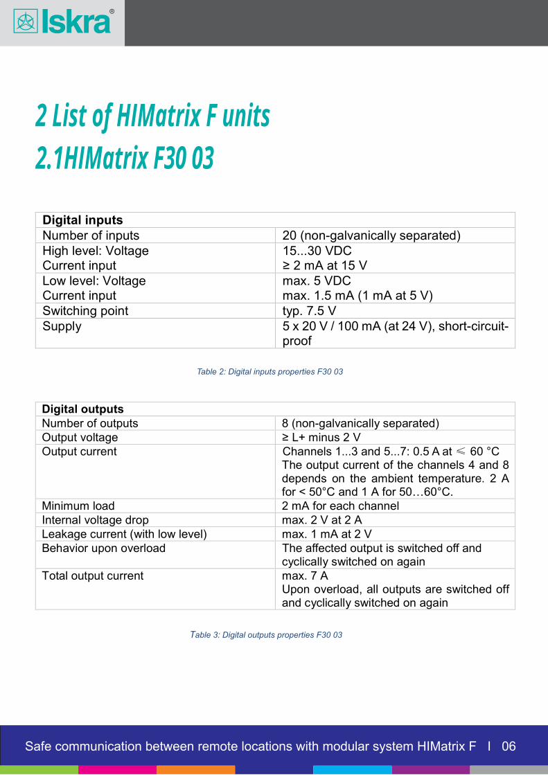
2.1HIMatrix F30 03
Digital inputs Number of inputs 20 (non-galvanically separated) High level: Voltage Current input
15...30 VDC ≥ 2 mA at 15 V
Low level: Voltage Current input
max. 5 VDC max. 1.5 mA (1 mA at 5 V)
Switching point typ. 7.5 V Supply 5 x 20 V / 100 mA (at 24 V), short-circuit-
proof
Table 2: Digital inputs properties F30 03
Digital outputs
Number of outputs 8 (non-galvanically separated) Output voltage ≥ L+ minus 2 V Output current Channels 1...3 and 5...7: 0.5 A at ≤ 60 °C
The output current of the channels 4 and 8 depends on the ambient temperature. 2 A for < 50°C and 1 A for 50…60°C.
Minimum load 2 mA for each channel Internal voltage drop max. 2 V at 2 A Leakage current (with low level) max. 1 mA at 2 V Behavior upon overload The affected output i s switched off and
cyclically switched on again Total output current max. 7 A
Upon overload, all outputs are switched off and cyclically switched on again
Table 3: Digital outputs properties F30 03
Safe communication between remote locations with modular system HIMatrix F I 07
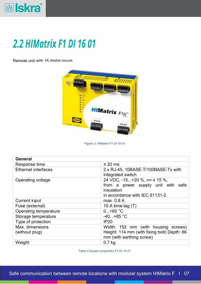
2.2 HIMatrix F1 DI 16 01
Remote unit with 16 digital inputs
Figure 2: HIMatrix F1 DI 16 01
General Response time ≥ 20 ms Ethernet interfaces 2 x RJ-45, 10BASE-T/100BASE-Tx with
integrated switch Operating voltage 24 VDC, -15...+20 %, rPP ≤ 15 %,
from a power supply unit with safe insulation in accordance with IEC 61131-2
Current input max. 0.8 A Fuse (external) 10 A time-lag (T) Operating temperature 0...+60 °C Storage temperature -40...+85 °C Type of protection IP20 Max. dimensions (without plug)
Width: 152 mm (with housing screws) Height: 114 mm (with fixing bolt) Depth: 66 mm (with earthing screw)
Weight 0.7 kg
Table 4:System properties F1 DI 16 01

Safe communication between remote locations with modular system HIMatrix F I 08
Digital inputs Number of inputs 16 (non-galvanically separated) High level: voltage current input
15...30 VDC ≥ 2 mA at 15 V
Low level: voltage current input
max. 5 VDC max. 1.5 mA (1 mA at 5 V)
Switching point typ. 7.5 V Switching time 250 s Supply 4 x 19.2 V / 40 mA (at 24 V), short-
circuit-proof
2.2 HIMatrix F1 DI 16 01
Table 5: Digital inputs properties F1 DI 16 01
Safe communication between remote locations with modular system HIMatrix F I 09
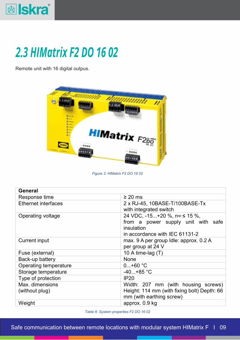
2.3 HIMatrix F2 DO 16 02Remote unit with 16 digital outpus.
Figure 3: HIMatrix F2 DO 16 02
General
Response time ≥ 20 ms Ethernet interfaces 2 x RJ-45, 1 0BASE-T/100BASE-Tx
with integrated switch Operating voltage 24 VDC, -15...+20 %, rPP ≤ 15 %,
from a power supply unit with safe insulation in accordance with IEC 61131-2
Current input max. 9 A per group Idle: approx. 0.2 A per group at 24 V
Fuse (external) 10 A time-lag (T) Back-up battery None Operating temperature 0...+60 °C Storage temperature -40...+85 °C Type of protection IP20 Max. dimensions (without plug)
Width: 207 mm (with housing screws) Height: 114 mm (with fixing bolt) Depth: 66 mm (with earthing screw)
Weight approx. 0.9 kg
Table 6: System properties F2 DO 16 02
Safe communication between remote locations with modular system HIMatrix F I 10
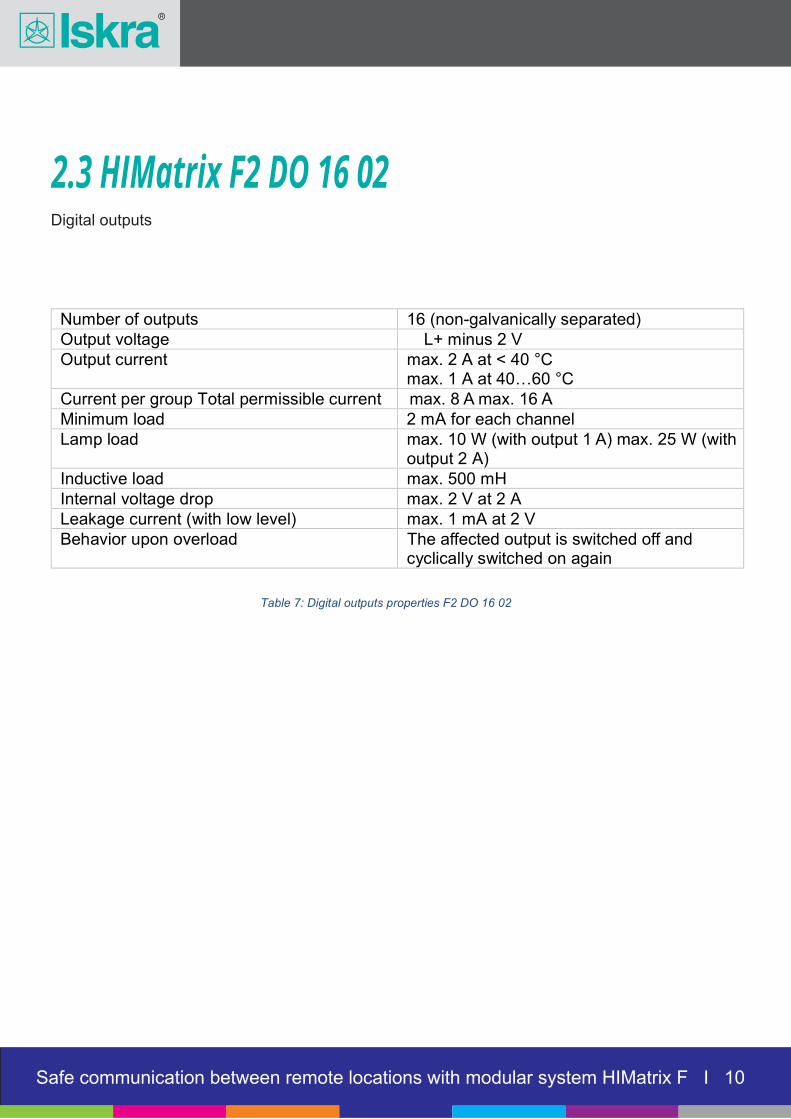
2.3 HIMatrix F2 DO 16 02
Table 7: Digital outputs properties F2 DO 16 02
Number of outputs 16 (no n-galvanically separated) Output voltage L+ minus 2 V Output current max. 2 A at < 40 °C
max. 1 A at 40…60 °C Current per group Total permissible current max. 8 A max. 16 A Minimum load 2 mA for each channel Lamp load max. 10 W (with output 1 A) max. 25 W (with
output 2 A) Inductive load max. 500 mH Internal voltage drop max. 2 V at 2 A Leakage current (with low level) max . 1 mA at 2 V Behavior upon overload The affected output i s switched off and
cyclically switched on again
Digital outputs

Safe communication between remote locations with modular system HIMatrix F I 11
2.4 HIMatrix F3 DIO 8/8 01Remote unit with 8 digital units and 8 digital outputs.
Figure 4: Sistem HIMatrix F3 DIO 8/8 01
General Response time ≥ 20 ms Ethernet interfaces 2 x RJ-45, 10BA S E-T/100BASE-Tx with
integrated switch Operating voltage 24 VDC, -15...+20 %, rPP ≤ 15 %,
from a power supply unit with safe insulation in accordance with IEC 61131-2
Current input max. 8 A (wit h maximum load) Idle: approx.group at 24 V
Fuse (external) 10 A time-lag (T) Back-up battery None Operating temperature 0...+60 °C Storage temperature -40...+85 °C Type of protection IP20 Max. dimensions (without plug)
Width: 207 mm (with housing screws) Height: 114 mm (with fixing bolt) Depth: 66 mm (with earthing screw)
Weight approx. 0.9 kg
Table 6: System properties F2 DO 16 02

Safe communication between remote locations with modular system HIMatrix F I 12
2.4 HIMatrix F3 DIO 8/8 01
Table 9: Digital inputs properties F3 DIO 8/8 01
Digital inputs Number of inputs 8 (non-galvanically separated) High level: Voltage Current input
15...30 VDC ≥ 2 mA at 15 V
Low level: Voltage Current input
max. 5 VDC max. 1.5 mA (1 mA at 5 V)
Switching point typ. 7.5 V Supply 2 x 20 V / 100 mA (at 24 V), short-
circuit-proof
Digital outputs (DO+ and DO-) Number of outputs DO+ L+ switching
8 (non-galvanically separated) Common ground L-
Number of outputs DO- L- switching
2 (non-galvanically separated) Common ground S+
Output voltage ≥ L+ minus 2 V Output current DO+ Channels 1...3 an d 5...7: 0.5 A up to 60 °C
The output current of the channels 4 and 8 depends on the ambient temperature.
Output current DO- The output current of the channels 4 and 8 depends on the ambient temperature.
Lamp load, max.: DO+ channel 1...3 and 5...7 DO+ channel 4 and 8 DO- channel 4 and 8
10 W 25 W 25 W
Inductive load, max.: DO+ channel 1...3 and 5...7 DO+ channel 4 and 8 DO- channel 4 and 8
500 mH 500 mH 500 mH
Minimum load 2 mA for each channel
Internal voltage drop max. 2 V at 2 A
Behavior upon overload The affected output is switched off and cyclically switched on again
Total output current max. 7 A, upon overload, all outputs are switched off and cyclically switched on again
Table 10: Digital outputs properties F3 DIO 8/8 01
Safe communication between remote locations with modular system HIMatrix F I 13
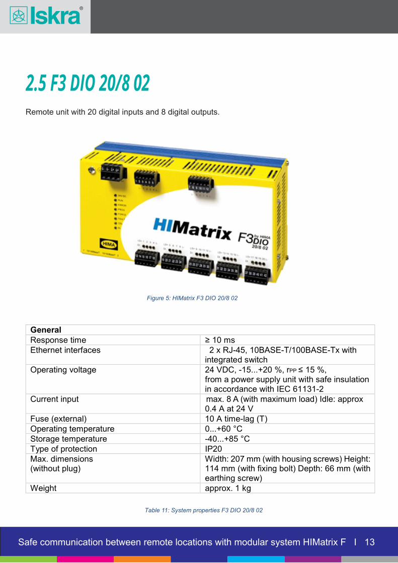
2.5 F3 DIO 20/8 02Remote unit with 20 digital inputs and 8 digital outputs.
Figure 5: HIMatrix F3 DIO 20/8 02
General
Response time ≥ 10 ms Ethernet interfaces 2 x RJ-45, 10 BASE-T/100BASE-Tx with
integrated switch Operating voltage 24 VDC, -15...+20 %, rPP ≤ 15 %,
from a power supply unit with safe insulation
in accordance with IEC 61131-2 Current input max. 8 A (with maximum load) Idle: approx
0.4 A at 24 V Fuse (external) 10 A time-lag (T) Operating temperature 0...+60 °C Storage temperature -40...+85 °C Type of protection IP20 Max. dimensions (without plug)
Width: 207 mm (with housing screws) Height: 114 mm (with fixing bolt) Depth: 66 mm (with earthing screw)
Weight approx. 1 kg
Table 11: System properties F3 DIO 20/8 02
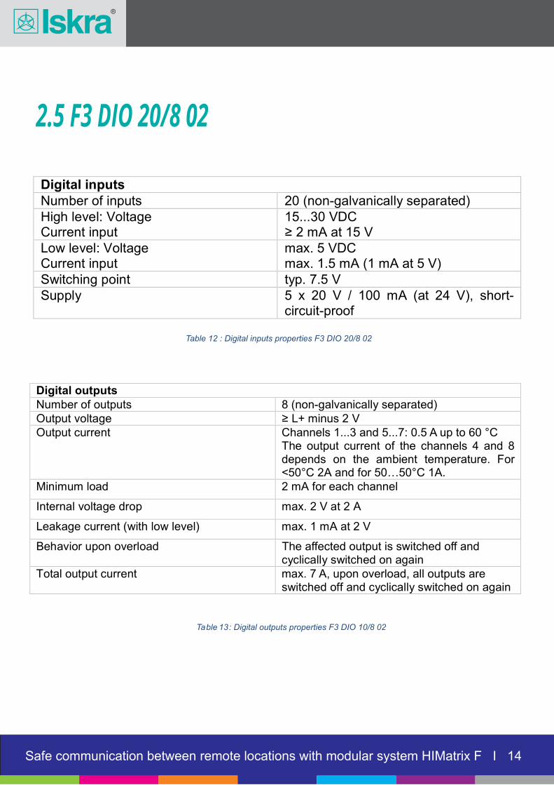
Digital inputs
Number of inputs 20 (non-galvanically separated) High level: Voltage Current input
15...30 VDC ≥ 2 mA at 15 V
Low level: Voltage Current input
max. 5 VDC max. 1.5 mA (1 mA at 5 V)
Switching point typ. 7.5 V Supply 5 x 20 V / 100 mA (at 24 V), short-
circuit-proof
2.5 F3 DIO 20/8 02
Table 12 : Digital inputs properties F3 DIO 20/8 02
Table 13 : Digital outputs properties F3 DIO 10/8 02
Digital outputs Number of outputs 8 (non-galvanically separated) Output voltage ≥ L+ minus 2 V Output current Channels 1 ...3 and 5...7: 0.5 A up to 60 °C
The output current of the channels 4 and 8 depends on the ambient temperature. For <50°C 2A and for 50…50°C 1A.
Minimum load 2 mA for each channel
Internal voltage drop max. 2 V at 2 A
Leakage current (with low level) ma x. 1 mA at 2 V
Behavior upon overload The affected outpu t is switched off and cyclically switched on again
Total output current max. 7 A, upon overload, all outputs are switched off and cyclically switched on again
Safe communication between remote locations with modular system HIMatrix F I 14

3 Use of different transsmision media
3.1 Copper (twisted pair, two pairs)
Safe communication between remote locations with modular system HIMatrix F I 05
In case of copper connection xDSL modems are used to provide needed ethernet connection.
3.2 Optic fibreIf we have acess to optic fibre we need FO/UTP converters.In case client has set transfer system, we need ethernet connection between locations (VLAN).
3.3 WLANWhen wireless network is used, we need acess point, which provides us UTP connection to device.
Safe communication between remote locations with modular system HIMatrix F I 15

4 Software
Figure 6: Example of hardware configuration in program
IIn program we first select main unit and remote units that are needed. Safeethernet communication between them is established automatically.
On figure 6 we have example of establishing connection between three remote units. First location (Hekimhan) have main unit F30 03 and one remote output unit F2 DO 16 01. Second location (BP78) has two remote input units F1 DI 16 01 nad one remote output unit F1 DO 16 01. Third location (Hassansalebi) has only one remote output unit F2 DO 16 01.
When hardware is set, we create and assign variable for each input and output.
Connections between inputs and outputs needs to be created. Function block “1input-1output” are used for transfering signal from one source to one remote location and function block “1input-2outputs” for transfering signal from one source to two remote locations.
Safe communication between remote locations with modular system HIMatrix F I 05Safe communication between remote locations with modular system HIMatrix F I 16

4 Software
Safe communication between remote locations with modular system HIMatrix F I 05
Figure 7: Example of use of function blocks ''1input-1output'' and ''1input-2outputs''
Currently only this two function blocks are user, but system enables transfer of sigal from one source to any number of remote locations, at the same time we could build in filtering and processing samped signals.
Safe communication between remote locations with modular system HIMatrix F I 05Safe communication between remote locations with modular system HIMatrix F I 17
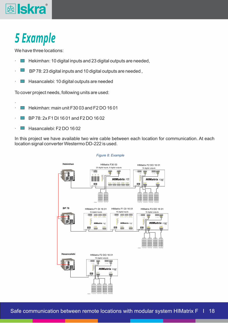
5 Example
Safe communication between remote locations with modular system HIMatrix F I 05
We have three locations:
· Hekimhan: 10 digital inputs and 23 digital outputs are needed,
· BP 78: 23 digital inputs and 10 digital outputs are needed ,
· Hasancalebi: 10 digital outputs are needed
To cover project needs, following units are used:
·· Hekimhan: main unit F30 03 and F2 DO 16 01
· BP 78: 2x F1 DI 16 01 and F2 DO 16 02
· Hasancalebi: F2 DO 16 02
In this project we have available two wire cable between each location for communication. At each location signal converter Westermo DD-222 is used.
Figure 8: Example
Safe communication between remote locations with modular system HIMatrix F I 05Safe communication between remote locations with modular system HIMatrix F I 05Safe communication between remote locations with modular system HIMatrix F I 18
Hekimhan
BP 78
Hasancelebi
HIMatrix F30 0320 digital inputs, 8 digital outputs
HIMatrix F2 DO 16 0116 digital outputs
HIMatrix F1 DI 16 0116 digital inputs
HIMatrix F1 DI 16 0116 digital inputs
HIMatrix F2 DO 16 0116 digital outputs
TR
S 2
4V
DC
1C
O
TR
S 2
4V
DC
1C
O
TR
S 2
4V
DC
1C
O
TR
S 2
4V
DC
1C
O
TR
S 2
4V
DC
1C
O
TR
S 2
4V
DC
1C
O
TR
S 2
4V
DC
1C
O
TR
S 2
4V
DC
1C
O
TR
S 2
4V
DC
1C
O
TR
S 2
4V
DC
1C
O
TR
S 2
4V
DC
1C
O
TR
S 2
4V
DC
1C
O
TR
S 2
4V
DC
1C
O
TR
S 2
4V
DC
1C
O
TR
S 2
4V
DC
1C
O
TR
S 2
4V
DC
1C
O
TR
S 2
4V
DC
1C
O
TR
S 2
4V
DC
1C
O
TR
S 2
4V
DC
1C
O
TR
S 2
4V
DC
1C
O
TR
S 2
4V
DC
1C
O
TR
S 2
4V
DC
1C
O
TR
S 2
4V
DC
1C
O
TR
S 2
4V
DC
1C
O
TR
S 2
4V
DC
1C
O
TR
S 2
4V
DC
1C
O
TR
S 2
4V
DC
1C
O
TR
S 2
4V
DC
1C
O
TR
S 2
4V
DC
1C
O
TR
S 2
4V
DC
1C
O
TR
S 2
4V
DC
1C
O
TR
S 2
4V
DC
1C
O
TR
S 2
4V
DC
1C
O
TR
S 2
4V
DC
1C
O
TR
S 2
4V
DC
1C
O
TR
S 2
4V
DC
1C
O
TR
S 2
4V
DC
1C
O
TR
S 2
4V
DC
1C
O
TR
S 2
4V
DC
1C
O
TR
S 2
4V
DC
1C
O
HIMatrix F2 DO 16 0116 digital outputs
TR
S 2
4V
DC
1C
O
TR
S 2
4V
DC
1C
O
TR
S 2
4V
DC
1C
O
TR
S 2
4V
DC
1C
O
TR
S 2
4V
DC
1C
O
TR
S 2
4V
DC
1C
O
TR
S 2
4V
DC
1C
O
TR
S 2
4V
DC
1C
O
TR
S 2
4V
DC
1C
O
TR
S 2
4V
DC
1C
O
TR
S 2
4V
DC
1C
O
TR
S 2
4V
DC
1C
O
TR
S 2
4V
DC
1C
O
TR
S 2
4V
DC
1C
O
TR
S 2
4V
DC
1C
O
TR
S 2
4V
DC
1C
O
Outputs: 1 2 3 4 5 6 7 8 9 10 11 12 13 14 15 16 17 18 19 20 21 22 23 24
Outputs: 1 2 3 4 5 6 7 8 9 10 11 12 13 14 15 16
Outputs: 1 2 3 4 5 6 7 8 9 10 11 12 13 14 15 16
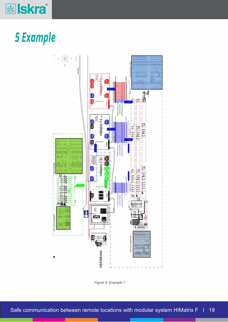
5 Example
Figure 9: Example 1
Safe communication between remote locations with modular system HIMatrix F I 05Safe communication between remote locations with modular system HIMatrix F I 05Safe communication between remote locations with modular system HIMatrix F I 05Safe communication between remote locations with modular system HIMatrix F I 19
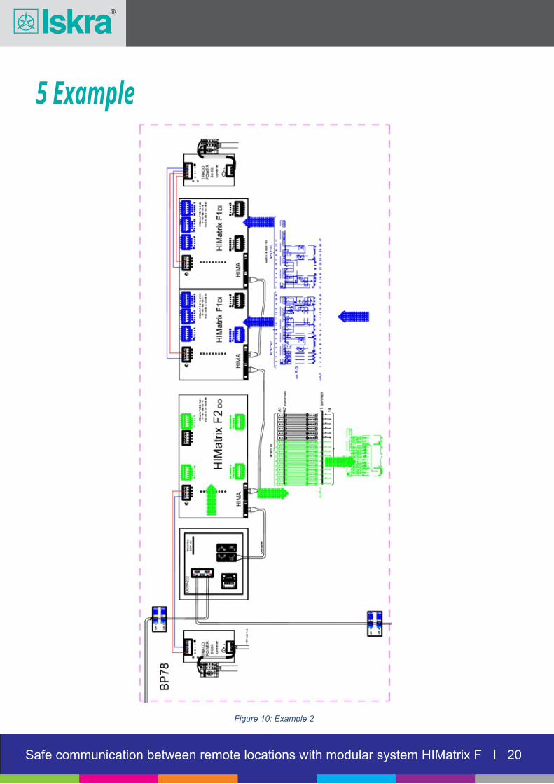
5 Example
Figure 10: Example 2
Safe communication between remote locations with modular system HIMatrix F I 05Safe communication between remote locations with modular system HIMatrix F I 05Safe communication between remote locations with modular system HIMatrix F I 05Safe communication between remote locations with modular system HIMatrix F I 20

5 Example
Figure 11: Example 3
Safe communication between remote locations with modular system HIMatrix F I 05Safe communication between remote locations with modular system HIMatrix F I 05Safe communication between remote locations with modular system HIMatrix F I 05Safe communication between remote locations with modular system HIMatrix F I 21