Safe Automotive soFtware architEcture (SAFE)safe-project.eu/SAFE-Publications/SAFE_D3.1.2.c.pdf ·...
41
SAFE – an ITEA2 project D3.1.2.c 2013 The SAFE Consortium 1 (41) Contract number: ITEA2 – 10039 Safe Automotive soFtware architEcture (SAFE) ITEA Roadmap application domains: Major: Services, Systems & Software Creation Minor: Society ITEA Roadmap technology categories: Major: Systems Engineering & Software Engineering Minor 1: Engineering Process Support WP 3 Deliverable D3.1.2c: Update of final proposal for extension of SAFE meta model for safety requirement expression modeling Due date of deliverable: 28/02/2013 Actual submission date: 31/12/2013 Start date of the project: 01/07/2011 Duration: 42 months WT coordinator name: Eduard Metzker Organization name of lead contractor for this deliverable: Vector Informatik Editor: WT3.1.2 members (Mohamed Abbaz, Elvira Biendl, Alain Griffault, Eduard Metzker, Thomas Peikenkamp, Hans Leo Ross) Contributors: WT3.1.2 members (Mohamed Abbaz, Elvira Biendl, Alain Griffault, Eduard Metzker, Thomas Peikenkamp, Hans Leo Ross)
Transcript of Safe Automotive soFtware architEcture (SAFE)safe-project.eu/SAFE-Publications/SAFE_D3.1.2.c.pdf ·...

SAFE – an ITEA2 project D3.1.2.c
2013 The SAFE Consortium 1 (41)
Contract number: ITEA2 – 10039
Safe Automotive soFtware architEcture (SAFE)
ITEA Roadmap application domains:
Major: Services, Systems & Software Creation
Minor: Society
ITEA Roadmap technology categories:
Major: Systems Engineering & Software Engineering
Minor 1: Engineering Process Support
WP 3
Deliverable D3.1.2c: Update of final proposal for
extension of SAFE meta model for safety requirement
expression modeling Due date of deliverable: 28/02/2013
Actual submission date: 31/12/2013
Start date of the project: 01/07/2011 Duration: 42 months
WT coordinator name: Eduard Metzker
Organization name of lead contractor for this deliverable: Vector Informatik
Editor: WT3.1.2 members (Mohamed Abbaz, Elvira Biendl, Alain Griffault, Eduard Metzker, Thomas Peikenkamp, Hans Leo Ross)
Contributors: WT3.1.2 members (Mohamed Abbaz, Elvira Biendl, Alain Griffault, Eduard Metzker, Thomas Peikenkamp, Hans Leo Ross)

SAFE – an ITEA2 project D3.1.2.c
2013 The SAFE Consortium 2 (41)
Revision chart and history log
Version Date Reason
0.1 20.02.2012 Vector: Initial setup for sharing input from project partners
0.2
0.3
24.02.2012
05.03.2012
Vector: Contribution of PREEvision EEA
All: Joint review of contributions
0.4 14.03.2012 Vector: AUTOSAR 4.0 analysis
0.5 28.03.2012 Valeo: contribution update: section 5.4, 2.5, 2.9
0.6 11.04.2012 Valeo: section 5.4, 2.5, 2.9 internal review
0.7 16.04.2012 ?: section 5.4, 2.5, 2.9 from other document (draft) transfer into deliverable document to 5.4, 7.5, 7.9.
0.8 30.04.2012 Vector: Improved meta-model concepts for requirements refinement and allocation, removed working annotations
0.9 20.06.2012 Vector: Moved requirement mapping to WP2 to report document
1.0 20.06.2012 Vector: Updated pictures and descriptions to latest meta model version
1.1 27.06.2012 Vector: integrated review comments
1.2 11.02.2013 Vector: updated the description of the SAFE concepts for safety requirements expression
1.3 18.02.2013 Vector: Integrated review comments from Telco
1.4 08.03.2013 Vector: Final editing
1.5. 02.12.2013 Integrated feedback from OEM advisory board

SAFE – an ITEA2 project D3.1.2.c
2013 The SAFE Consortium 3 (41)
1 Table of contents
1 Table of contents ........................................................................................................................................ 3
2 List of figures .............................................................................................................................................. 5
3 Executive Summary .................................................................................................................................... 6
4 Introduction ................................................................................................................................................. 7
5 Related Approaches ................................................................................................................................... 8
5.1 Safety Requirement Modeling in the meta model of PREEvision ....................................................... 8
5.1.1 Safety Requirements as subtypes of requirements .................................................................... 9
5.1.2 ASIL and ASIL decomposition of safety requirements ............................................................... 9
5.1.3 Relation of Safety Goals to Hazards ......................................................................................... 10
5.2 Safety requirements modeling concepts in AUTOSAR 4.0 .............................................................. 10
5.3 Safety requirements modeling according to CESAR ........................................................................ 10
5.3.1 Methodology ............................................................................................................................. 11
5.3.1.1 Introduction to the CESAR methodology ............................................................................................ 11
5.3.1.2 Requirements Elicitation and Specification ......................................................................................... 11
5.3.1.3 Requirements Analysis ....................................................................................................................... 12
5.3.1.4 Requirements Change Management .................................................................................................. 12
5.3.1.5 Conclusion .......................................................................................................................................... 13
5.3.2 Requirement Specification Language ....................................................................................... 13
5.3.3 Safety Pattern ........................................................................................................................... 15
5.3.4 Example Scenario ..................................................................................................................... 17
5.3.4.1 Creating a new Pattern Contract file ................................................................................................... 17
5.3.4.2 Performing a Safety Pattern Analysis ................................................................................................. 22
5.4 Refinement of Safety Requirements according to ISO 26262 .......................................................... 24
5.4.1 Safety Requirements according to ISO 26262 concept phase ................................................. 25
5.4.2 Safety Requirements according to ISO 26262 product development at the system level ........ 25
5.4.3 Safety Requirements according to ISO 26262 product development at the hardware level .... 26
5.4.4 Safety Requirements according to ISO 26262 product development at the Software level ..... 27
5.4.5 Traceability of Safety Requirements overview (Synthesis) ...................................................... 28
5.4.6 Interfaces between Safety Requirements, Safety Concept and Safety Analysis ..................... 29
6 SAFE modeling concepts ......................................................................................................................... 33
6.1 Expression of formal safety requirements ........................................................................................ 33
6.1.1 TraceableSpecification ............................................................................................................. 33
6.1.2 Abstract Safety Requirement .................................................................................................... 33
6.1.3 Safety Goal ............................................................................................................................... 34
6.1.4 Functional Safety Requirement ................................................................................................ 34

SAFE – an ITEA2 project D3.1.2.c
2013 The SAFE Consortium 4 (41)
6.1.5 Technical Safety Requirement .................................................................................................. 34
6.1.6 Safe State ................................................................................................................................. 35
6.2 Refinement of safety requirements ................................................................................................... 35
6.2.1 Requirement Link ...................................................................................................................... 36
6.2.2 Requirement Link Type ............................................................................................................. 36
6.3 Allocation of safety requirements ...................................................................................................... 37
6.3.1 Allocations................................................................................................................................. 37
6.3.2 Allocatable Element .................................................................................................................. 38
6.3.3 AllocationTarget ........................................................................................................................ 38
7 Discussion and Future Improvements ...................................................................................................... 39
8 Acknowledgements................................................................................................................................... 40
9 References ............................................................................................................................................... 41

SAFE – an ITEA2 project D3.1.2.c
2013 The SAFE Consortium 5 (41)
2 List of figures
Figure 1: Management of safety requirements in PREEvision ......................................................... 8
Figure 2: Safety requirements as subtypes of requirements............................................................ 9
Figure 3: ASIL and ASIL decomposition ........................................................................................ 10
Figure 4: Relation to Hazards ........................................................................................................ 10
Figure 5: Create PatternContracts file ........................................................................................... 17
Figure 6: Create new object .......................................................................................................... 18
Figure 7: Run Pattern Editor .......................................................................................................... 18
Figure 8: Create additional contract .............................................................................................. 18
Figure 9: Edit contract name ......................................................................................................... 19
Figure 10: Create Assumption/Promise ......................................................................................... 19
Figure 11: Edit assumption properties ........................................................................................... 20
Figure 12: Save changes .............................................................................................................. 21
Figure 13: Pattern Contracts ......................................................................................................... 22
Figure 14: Run Safety Pattern Analysis ......................................................................................... 22
Figure 15: Select analysis type and choose root folder ................................................................. 23
Figure 16: Available contracts (left), Selected top-level and dominating contracts (right) .............. 23
Figure 17: Run analysis ................................................................................................................. 24
Figure 18: Results shown in Status Log ........................................................................................ 24
Figure 19: Traceability of safety requirements overview ................................................................ 28
Figure 20: Idea of Safety Requirement Traceability (Functional View) .......................................... 29
Figure 21: overview interfaces between safety requirement allocation from safety concept to lower level and results of safety analysis ................................................................................................ 30
Figure 22: overview of safety requirement allocation from safety concept to lower level and results of safety analysis ........................................................................................................................... 30
Figure 23: Concept: Safety Requirements ..................................................................................... 33
Figure 24: Overview of concept for refinement of safety requirements .......................................... 36
Figure 25: Overview of concept for safety requirements allocation ................................................ 37
SAFE – an ITEA2 project D3.1.2.c
2013 The SAFE Consortium 6 (41)
3 Executive Summary
This document describes how the modeling of safety requirements is supported in the SAFE meta model. The elements of the SAFE meta model for safety requirements are described and their relationships to each other. Furthermore the concepts which support requirements refinement, allocation and traceability are described.

SAFE – an ITEA2 project D3.1.2.c
2013 The SAFE Consortium 7 (41)
4 Introduction
This document describes how safety requirements are expressed in the SAFE meta model. Chapter 5 describes related approaches which have been taken into account for the SAFE meta model. Chapter 6 describes the details of the SAFE safety requirements model. The characteristics of safety requirements are explained together with the relation of safety requirements to environments and hazards. Furthermore the traceability of safety requirements is supported by using the concepts of requirement links and requirement allocations. Requirements links and allocations are also described as means for refining safety requirements and associating safety requirements with artifacts of the architecture.
SAFE – an ITEA2 project D3.1.2.c
2013 The SAFE Consortium 8 (41)
5 Related Approaches
This chapter describes contributions from relevant related approaches to the modeling of safety requirements.
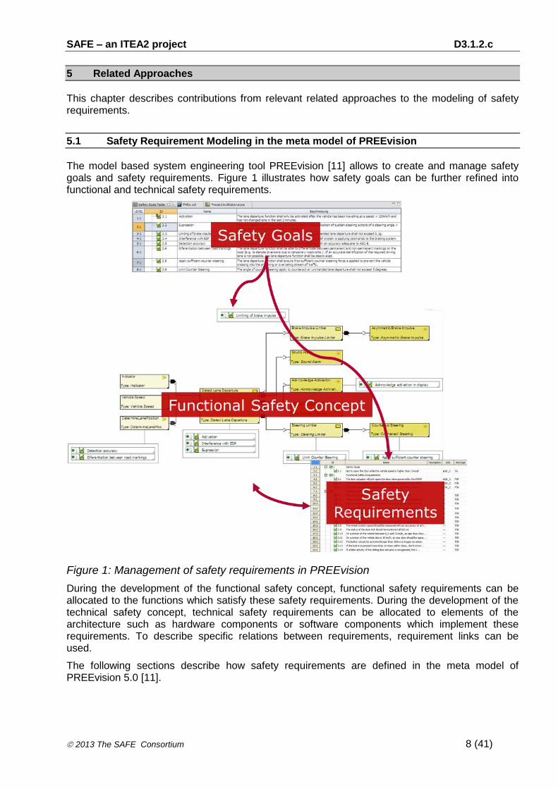
5.1 Safety Requirement Modeling in the meta model of PREEvision
The model based system engineering tool PREEvision [11] allows to create and manage safety goals and safety requirements. Figure 1 illustrates how safety goals can be further refined into functional and technical safety requirements.
Figure 1: Management of safety requirements in PREEvision
During the development of the functional safety concept, functional safety requirements can be allocated to the functions which satisfy these safety requirements. During the development of the technical safety concept, technical safety requirements can be allocated to elements of the architecture such as hardware components or software components which implement these requirements. To describe specific relations between requirements, requirement links can be used.
The following sections describe how safety requirements are defined in the meta model of PREEvision 5.0 [11].

SAFE – an ITEA2 project D3.1.2.c
2013 The SAFE Consortium 9 (41)
5.1.1 Safety Requirements as subtypes of requirements
Figure 2: Safety requirements as subtypes of requirements
In PREEvisions meta model safety requirements are defined as subtypes of requirements. The meta model artifacts reflect the following definitions in the ISO Standard [4],[5].
OperationalSituation: ISO 26262-3: 7.4.4.1
OperatingMode: ISO 26262-3: 7.4.4.1
SafetyGoal: ISO 26262-3: 7.4.8
SafeState: ISO 26262-3: 7.4.8
FunctionalSafetyRequirement: ISO 26262-3: 8.4.2.3
TechnicalSafetyRequirement: ISO 26262-4: 6.4.9
SafetyGoals are typically associated with SafeStates and SafeStates are typically associated to SafetyGoals.
FunctionalSafetyRequirements are typically associated to SafetyGoals, SafeStates and OperatingModes. They also describe any functional redundancies.
TechnicalSafetyRequirements are typically associated with FunctionalSafetyRequirements and SafeStates. They typically describe transitions to SafeStates and measures to maintain the safe state.
5.1.2 ASIL and ASIL decomposition of safety requirements

SAFE – an ITEA2 project D3.1.2.c
2013 The SAFE Consortium 10 (41)
Figure 3: ASIL and ASIL decomposition
Safety requirements are subtypes of the abstract meta model artefact HasASILDecomposed. ASIL decomposition of safety requirements is supported as defined in ISO 26262-9: 8.4.3 [10].
5.1.3 Relation of Safety Goals to Hazards
Figure 4: Relation to Hazards
Safety goals have relations to the hazards based on which the safety goals have been derived.
5.2 Safety requirements modeling concepts in AUTOSAR 4.0
AUTOSAR 4.0 does not provide any dedicated artifacts for modeling safety requirements such as safety goals, functional safety requirements or technical safety requirements.
5.3 Safety requirements modeling according to CESAR

SAFE – an ITEA2 project D3.1.2.c
2013 The SAFE Consortium 11 (41)
5.3.1 Methodology
Requirements engineering is a fundamental part in the development of safety related embedded systems. It comprises many different disciplines like elicitation, development, analysis, validation, communication and management of requirements. Each of these disciplines has its own technologies and relation to system artifacts. Therefore it is not surprising, that a variety of tools – industrial as well as academic -- are used to cover a complete and consistent requirements engineering process as already required by modern safety standards.
In the CESAR (Cost-efficient methods and processes for safety relevant embedded systems) project [12] an approach for integrating these tools, their data formats, and the requirements engineering process has been developed. Technologies like the CMM (Meta-Model developed in CESAR), the interoperability platform CMM-API (CESAR meta model application programming interface) and many adapted validation and verification techniques enabled the creation of a requirements engineering framework integrating commonly used tools and methods.
5.3.1.1 Introduction to the CESAR methodology
New standards for the development of safety critical embedded systems require a sophisticated requirements engineering process. Consistency of requirements needs to be ensured, validation and verification methods need to be applied to the requirements and the architecture, and a full traceability between all system artifacts has to be maintained. Due to the complexity of these tasks a huge amount of tools is available to support the user in single activities. Ensuring a consistent process is complicated by the different data formats, storage locations and used methodologies.
In the CESAR project these boundaries shall be overcome by developing an interoperable, consistent and adaptable requirements engineering process. The heart of the approach is the CMM-API, an interoperability approach based on the meta-model developed in the project (CMM). This API allows to access arbitrary system artifacts from different repositories like the IBM DOORS database, a Requisite Pro repository or the ModelBus in multiple formats like AUTOSAR, EAST-ADL. The approach itself is not limited to requirements engineering, but has been developed with this use case in mind. This way the traceability between system elements distributed across different storage location and data formats is possible with an easy to use interface. Furthermore the contract based approach is fully integrated, enabling all connected tools to specify requirements in assumptions and promises.
The integration of system artifacts, requirements and verification and validation activities (V\&V cases) in one homogeneous CMM representation enables the creation of a consistent and interoperable requirements process compliant to the needs of modern safety standards like the ISO 26262.
5.3.1.2 Requirements Elicitation and Specification
As the development of systems is based on the identified and developed requirements it is important that requirements accurately capture the stakeholder needs, are well-understood and verifiable. Due to that, requirements engineering guidelines and safety standards request several constraints on requirement statements like well-formedness, unambiguity and formalization. Moreover, requirements should be consistent and they should be satisfied by the proposed implementation. Formal notations – already recommended by some safety standards – provide a clear semantics of requirements and allow formal analysis methods applied to requirements alleviating V\&V. But writing requirements in a formal notation is not an easy task.
Within the CESAR project formalizing and management of requirements is addressed with a special focus on the interoperability of the developed methods and tools. A process starting from

SAFE – an ITEA2 project D3.1.2.c
2013 The SAFE Consortium 12 (41)
requirements given in natural language to a formal description is introduced consisting of several steps. Based on an ontology describing the domain (domain specific language), requirement statements are analyzed to identify actors, actions, and other items as well as the structure of the sentence to identify the characteristics of the statement. This is mapped to a sequence of predefined structural templates, so called boilerplates. A set of analysis methods supports the process. In a second step the boilerplates are transformed into the formal pattern language. RSL patterns are templates too, but in contrast to boilerplates they are based on a complete formal language enabling complex semantic analysis regarding safety, functionality, real-time and other aspects.
According to the principles of interoperability the degree of formalization and the used language is independent from the tools and repositories used. All three languages can be used with the CMM-API connected tools like IBM DOORS and IBM Requisite Pro as well as locally or remotely stored files. Also specialized artifacts of the languages are accessible in all storage formats, e.g. classifications of requirement parts through the ontology.
In addition to the requirements management itself also the traceability to the architecture is ensured in a modularized way. Design model adapters exist to allow a seamless integration of various formats like EAST-ADL, AUTOSAR or SIMULINK.
Using this approach the CESAR project proved that a methodology can be integrated in a development process regardless of the used tools by means of a suitable interoperability approach.
5.3.1.3 Requirements Analysis
Different storage locations, multiple requirements formats and varying degrees of formalization complicate the analyzability of requirements. Furthermore analyzes have to be performed at many stages of the development process ranging from early consistency and completeness analysis of requirements to satisfaction checks performed by formal methods or testing.
In the CESAR project we have obtained a sophisticated interlocking between the different aspects of requirement analysis. For both textual requirement specification languages consistency and completeness checks have been defined and implemented. The V\&V activities and their results are stored in CMM and thus independently analyzable. The Permeter tool allows evaluating the quality of the development process based on the V\&V part of the CMM. Thus a reliable reporting can be ensured.
Additional benefits are attended by the CMM-API interoperability approach. Outputs from of ontology based analyses can be reused for formal analyses to prove the upcoming doubts in the specification. Formal analyzes like Entailment can prove the correct derivation of requirements in sub-requirements or the existence of contradicting requirements identifying a high amount of problems before the actual building of the device has begun. Even in these later phases of the development process the integrated requirements engineering approach can ease the effort for testing the implementation. Out of the requirements specification in pattern based RSL observers can be generated in C-Code notation to evaluate the compliance to the requirements automatically during runtime of the test. An implementation for the BTC Embedded tester allows using these observers also for test vector generation to maintain a high level of coverage on the requirements.
It has been shown that requirements specification and their validation techniques can be fused is a consistent development process across the borders of data formats and storage locations. The semantic grounding of all artifacts allows an intensive reuse of the specification for validation activities, test vector generation and process monitoring.
5.3.1.4 Requirements Change Management

SAFE – an ITEA2 project D3.1.2.c
2013 The SAFE Consortium 13 (41)
The integration of many modeling and requirements tools in the design process of embedded systems typically complicate the reaction on changes in requirements since the data might be spread across different data formats and repositories. Using the CMM-API within the requirements engineering process the change management can be automated to a very high degree and safe a lot a revalidation effort.
Changes in the requirements of a product typically do not affect only the changed part itself but also a wide range of other parts of the system. In the worst case a changed requirement could result in the need of performing all verification and validation activities of the system again. A goal of the CESAR project was the development of an impact analysis capable of automatically detect the parts of the system which are not affected by a change and the parts that need to be adapted in order to implement the initial changed requirement.
Using the interoperability approach of the CMM-API is it possible to analyze impact on a homogeneous data view allowing tracking of changes between all connected tools and formats like IBM DOORS, Requisite Pro, AUTOSAR, EAST-ADL or Simulink. Although the analysis is applicable to any kind of requirements the highest degree of automation can be reached by using formalized requirements. As a formal language the pattern based RSL is used. The RSL is fully integrateable in the Contract Based Approach dividing a system requirement in an Assumption on the environment and a promise on the work a component shall fulfill. Based on the RSL embedded in contracts an entailment analysis has been developed in the SPEEDS and CESAR project that verifies the correct splitting of one requirement in multiple sub-requirements. These technologies allow us to determine the requirements which are not affected by the initial change and therefore do not need to be revalidated. Furthermore compensation strategies have been developed to determine if a rephrasing of multiple requirements could be sufficient to adapt to a change without any revalidation in a system.
Using the formal impact analysis process it is possible to drastically reduce the revalidation effort caused by changes in requirements across data format and repository boundaries.
5.3.1.5 Conclusion
Interoperability is an essential aspect of requirements engineering to cope with the various demands of modern safety standards. We have presented an approach how to combine the specification, the analysis and the management aspects of requirements in an interoperable framework based on the CMM. This exchange ability of information is not only limited to the pure exchange of system artifacts and the creation of links between them, but also provides the possibility to semantically interpret data. This common understanding of data enables many stunning use cases like the automatic generation of test cases out of the specification, the management of changes across tool boundaries and the automatic validation of requirements.
5.3.2 Requirement Specification Language
Stating requirements is one of the essential tasks in developing products. These requirements build an interface between different groups of people, i.e. customers, engineers, project managers and many more.
Typically requirements are stored as natural language text which has the disadvantage that ambiguities of the sentences can cause a huge amount of requirement changes in early as well in later development phases. To reduce the costs coming from these ambiguities formal languages are used to have a fixed semantic meaning for a requirement. But it does not only require some training to write requirements in these formal languages, it can also be hard to read them.
The pattern based RSL fills this gap by providing an easy to learn formal language with a fixed semantic that is still readable like natural language.

SAFE – an ITEA2 project D3.1.2.c
2013 The SAFE Consortium 14 (41)
Patterns consist of static text elements and attributes being filled in by the requirements engineer. Each pattern has a well defined semantic in order to ensure a consistent interpretation of the written system specification across all project participants. On the one hand this limits the possibilities of writing a requirement on the other hand it prevents misunderstandings regarding the interpretation of the sentences. To gain a set of unambiguous requirements this limitation is necessary. However writing requirements shall still be possible in an intuitive way. Patterns allow the writing of natural sounding requirements with defined semantics while being expressive enough to formalize complex requirements.
To gain a high degree of intuitivism the language shall consist of only a few constructs that can be easily remembered to give the requirement engineer the possibility to fully understand the RSL and choose the right pattern that fits the properties he wants to demand on the system.
There exist patterns for each of the following categories:
Functional Patterns These Patterns express functional requirements of the system. This includes the relationship between events, handling of conditions and invariants and the possibility to define intervals in which the requirements or parts of them are valid.
Probability Patterns In nearly all safety critical system it is necessary to express failure or hazard probabilities. Since there are various partly redundant forms of expressing probabilities that were used quite ambiguous in common speech, these patterns guide the requirements engineer to express his needs.
Safety related Patterns Only a small part of safety related requirements can be covered with probability patterns. The major part of the requirements outlines relationships between system components. These patterns enable the specification of single point of failures or other failure and hazard dependencies between different components.
Timing Patterns These patterns can be used to describe real-time behavior of systems. This includes periodic and aperiodic activations, jitter or delay.
Architecture Patterns These patterns specify the existence of architecture elements like components, events or connections between components.
Mapping Patterns
These patterns can be used to express requirements on the mapping from the functional design perspective to the physical design perspective.
Patterns are noted in a form with optional parts that are not necessarily instantiated. A functional pattern describing the causality between two events does look like this:
whenever request occurs response occurs during [0ms,10ms].
Phrases in square brackets are considered optional, bold elements are static keywords of the pattern and italic printed elements represent attributes that have to be filled out by the requirements engineer. When filling the attributes there are no general restrictions on the names but they should be descriptive. Concrete implementations of specification and analysis tools may introduce additional restrictions. The names of the attributes can be used later to be mapped to a given architecture or they can be used to generate the architecture. When specifying requirements

SAFE – an ITEA2 project D3.1.2.c
2013 The SAFE Consortium 15 (41)
there is no strict typing like int or real but there are categories that specify what is described by the different attributes.
To not complicate the language too much and to be also expressive enough the set of supported attributes has to be carefully chosen:
Event Events represent the activity in the system. An event can be for example a received signal, a user input by a pressed button, a computational result or the change of a value. Events occur at one point of time and have no duration in time.
Condition A condition is a logic and/or arithmetic expression based on variables and the status of events. Conditions can be used in two different ways in patterns. On the one hand they can be used as pseudo events to trigger an action if the condition becomes true. On the other hand the condition can be the system state that has to hold for a specified time. The values the condition is based on may change with time only.
Interval Intervals describe a continuous fragment of time which can have relative and quantitative time measures as delimiters or events. Intervals can be open “]x,y[“ or closed “[x,y]” or a combination of them.
Jitter Jitter of an event is the variation in the point of time of occurrence in a real time context. In this document jitter is considered as always positive, i.e. the event is delayed.
Component Components refer to entities that are able to handle events or condition variables. Typically these components refer to an actual architecture, but in early design stages, where the system has not been designed completely there are also “possible” component names allowed. These identifiers can either be used to generate the missing architecture or be mapped to the design in later development stages.
More details about the language and its semantics can be found in the CESAR deliverable [CESAR_D_SP2_R2.3_M3_v1.000_PU.pdf]. The next section focuses on a subset of patterns dedicated for the specification of safety requirements.
5.3.3 Safety Pattern
Safety requirements are a means to define the properties of a system's safety concept. The two main elements used within this section are failure-conditions and degradation-modes. With the pattern presented in this section it is possible to specify of the containment or propagation of faults.
The following attributes of are used in the patterns:
(1) Failure-Condition
(2) Degradation modes
1. A mode expression consists of a mode variable, a mode name and a relational operator(“==“, “!=“)
2. Example: DM==normal, DM != detected
(3) Expression, Expression Sets
1. An expression is either a failure-condition or a mode expression

SAFE – an ITEA2 project D3.1.2.c
2013 The SAFE Consortium 16 (41)
2. An expression set is a set of expressions
3. Example: {fail1, fail2, fail3 during dm=normal}
(4) perm()
1. If this operator is applied to an expression, the expression holds for all future states of the path
Pattern S1:
none of {<expr-set1>, …, <expr-setn>} occur
This pattern is used to describe the traces that are accepted / not accepted. Any trace that contains all elements of one expr-set is not accepted by the pattern.
Example Pattern:
none of {{f1,f2}, {f3,f4}} occur
Pattern S2:
expr1 only followed by expr2
Only traces will be accepted if any occurrence of expr1 will either be followed directly by expr2 or hold forever.
Example Pattern:
fail only followed by (DM==not-detected)
Pattern S3:
expr1 only after expr2
Only traces will be accepted if any occurrence of expr1 always occurs as a direct follower of expr2
Example Pattern:
(DM==detected) only after (DM==not-detected)
Pattern S4:
ModeVar is defined as (Mode1 , Mode2 , … , Moden)
This pattern is used to define existing modes for a mode variable.
Example Pattern:
DM is defined as (normal, notDetected, detected)
To specify that the modes can only occur in a specific order “<” can be used instead of “,”.

SAFE – an ITEA2 project D3.1.2.c
2013 The SAFE Consortium 17 (41)
Example Pattern:
DM is defined as (normal < notDetected < detected)
Pattern S5:
expr-set does not occur
This pattern is a derived pattern from S1. All expr-sets are stated in seprate patterns.
Example Pattern:
{f1,f2} does not occur
{f3,f4} does not occur
5.3.4 Example Scenario
5.3.4.1 Creating a new Pattern Contract file
Start DOORS and create a new folder. Run the setup script via the context menu as shown in Figure 5.
Figure 5: Create PatternContracts file
Open the formal module “PatternContracts” and create a new object (Figure 6).

SAFE – an ITEA2 project D3.1.2.c
2013 The SAFE Consortium 18 (41)
Figure 6: Create new object
Run the Pattern Editor as shown in Figure 6 to edit the created object. You are able to select between opening just the selected object or opening all objects in the Pattern Editor.
Figure 7: Run Pattern Editor
The Pattern Editor starts. Unfold the highest entry until you see the contract (yellow cube). If the highest entry is selected additional contracts can be created by using the “Create Contract” button (Figure 7). The small down arrow shows what kind of contracts can be created.
Figure 8: Create additional contract
By selecting the contract its name can be edited in the “Properties” view below (Figure 8).

SAFE – an ITEA2 project D3.1.2.c
2013 The SAFE Consortium 19 (41)
Figure 9: Edit contract name
If the contract is selected an assumption (left symbol, paper with blue line) and/or a promise (right symbol, paper with red line) can be created (Figure 9).
Figure 10: Create Assumption/Promise
If the “Assumption” is selected its pattern can be edited in the “Properties” view below (Figure 10). By clicking the small down arrow next to the “Pattern” text box a list of predefined patterns opens up. After selecting one of the patterns a small description is given in the “Description” window and the placeholder of the selected pattern can be filled by the text box in the “Pattern Properties” subsection below.
Editing the pattern of the “Promise” works in the same manner.

SAFE – an ITEA2 project D3.1.2.c
2013 The SAFE Consortium 20 (41)
Figure 11: Edit assumption properties
If all necessary contracts are created the changes have to be saved (Figure 11).

SAFE – an ITEA2 project D3.1.2.c
2013 The SAFE Consortium 21 (41)
Figure 12: Save changes
The created contracts will automatically be transferred into the “PatternContracts” file in DOORS (Figure 13).

SAFE – an ITEA2 project D3.1.2.c
2013 The SAFE Consortium 22 (41)
Figure 13: Pattern Contracts
5.3.4.2 Performing a Safety Pattern Analysis
To perform a safety pattern analysis select the equivalent entry in the “OFFIS Tools” menu (Figure 3-10).
Figure 14: Run Safety Pattern Analysis
In the drop down menu “Analysis Type” you can select between “Dominance Analysis” and “Consistency Check”. Under “DOORS Root Folder” the directory of the “PatternContracts” file is chosen. Click “Next” to continue the analysis (Figure 14).

SAFE – an ITEA2 project D3.1.2.c
2013 The SAFE Consortium 23 (41)
Figure 15: Select analysis type and choose root folder
On the left side you see the available contracts. Now you have to select the top-level event and have to push it with the arrow button into the “Top-Level Contract” pool on the right side of the window. Additionally you have to select the dominating contracts and have to push them into the “Dominating Contracts” pool. Continue by clicking “Next” (Figure 16).
Figure 16: Available contracts (left), Selected top-level and dominating contracts (right)
To start the safety pattern analysis press the marked button (Figure 17).

SAFE – an ITEA2 project D3.1.2.c
2013 The SAFE Consortium 24 (41)
Figure 17: Run analysis
The result of the analysis is shown in the “Status Log” section (Figure 3-14). In the case of errors the log file is shown by pressing the “Help” button. The analysis can be aborted via “Cancel” and if completed it can be closed with the “Finish” button.
Figure 18: Results shown in Status Log
5.4 Refinement of Safety Requirements according to ISO 26262

SAFE – an ITEA2 project D3.1.2.c
2013 The SAFE Consortium 25 (41)
This section describes refinement of safety requirement from Safety Goals to Functional and Technical Safety Requirements lower level requirements.
The explanation will be based on the ISO 26262 all parts refer to safety requirements specification.
For each part 3, 4, 5, 6 an identification of what contain need to be allocated for the safety requirement specification.
5.4.1 Safety Requirements according to ISO 26262 concept phase
Hazard analysis and risk assessment:
Safety goal expression:
A safety goal shall be determined for each hazardous event with an ASIL attribute evaluated in the
hazard analysis.
The ASIL level attribute shall defined for all safety requirements (include ASIL decomposition notation) to all safety requirements level.
Safety goal requirement (SG_Reqxx ASIL attribute) expression:
The safety goal shall contain:
- Safe state requirement (Saf_Reqxx) when applicable (If a safety goal can be achieved by transitioning to, or by maintaining, one or more safe states, then the corresponding safe state(s) shall be specified).
Functional safety concept:
Functional safety requirement:
Derive the functional safety requirements, from the safety goals, and to allocate them to the preliminary architectural.
Functional safety requirement (FS_Reqxx) shall be specified by considering (if applicable):
- operating modes,
- Fault tolerant time interval,
- Safe states,
- Emergency operation interval,
- Functional redundancies (e.g. fault tolerance).
Functional safety requirement with other technology and external measure:
- The functional safety requirements (FSOT_Reqxx) implemented by other technologies,
- The functional safety requirements (FSEM_Reqxx) implemented by external measures.
5.4.2 Safety Requirements according to ISO 26262 product development at the system
level

SAFE – an ITEA2 project D3.1.2.c
2013 The SAFE Consortium 26 (41)
Technical safety requirement: The technical safety requirements specification refines the functional safety concept.
1) The technical safety requirements shall specify safety-related dependencies between systems
(TSD_Reqxx)
2) The technical safety requirements shall specify the response of the system to stimuli that affect
the achievement of safety goals (TSR_Reqxx),
3) The technical safety requirements shall specify the necessary safety mechanisms
(TSSM_Reqxx) including:
- The measures relating to the detection, indication and control of faults in the system itself,
- The measures relating to the detection, indication and control of faults in external devices that interact with the system,
- The measures that enable the system to achieve or maintain a safe state
- The measures to detail and implement the warning and degradation concept,
- The measures which prevent faults from being latent.
3.1) Each safety mechanism that enables an item to achieve or maintain a safe state the following shall be specified:
- The transition to the safe state,
- The fault tolerant time interval,
- The emergency operation interval, if the safe state cannot be reached immediately,
- The measures to maintain the safe state.
4) Hardware-software interface specification (HSI) (TSHSI_Reqxx): The relevant diagnostic capabilities of the hardware and their use by the software shall be specified.
5.4.3 Safety Requirements according to ISO 26262 product development at the
hardware level
Hardware safety requirement: Hardware safety requirements specification for the hardware elements of the item shall be derived from the technical safety requirements allocated to hardware.
The hardware safety requirements specification (HWS_Reqxx) shall include each hardware requirement that relates to safety, including:
The hardware safety requirements and relevant attributes of safety mechanisms:
- To control internal failures of the hardware of the element, this includes internal safety mechanisms to cover transient faults when shown to be relevant due, for instance, to the technology used- fault tolerant time interval,
- To ensure the element is tolerant to failures external to the element,
- To comply with the safety requirements of other elements,
- To detect and signal internal or external failures,
- The hardware safety requirements not specifying safety mechanisms (i.e the target values for random hardware failures, single point,etc)

SAFE – an ITEA2 project D3.1.2.c
2013 The SAFE Consortium 27 (41)
- The HSI specification initiated in technical safety requirement, shall be refined sufficiently to allow for the correct control and usage of the hardware by the software, and shall describe each safety-related dependency between hardware and software.
5.4.4 Safety Requirements according to ISO 26262 product development at the
Software level
Software safety requirement: The software safety requirements shall address each software-based function whose failure could lead to a violation of a technical safety requirement allocated to software.
The specification of the software safety requirements shall be derived from the technical safety concept
The software safety requirements specification (SWS_Reqxx) shall consider:
- The specification and management of safety requirements,
- The specified system and hardware configurations,
- The hardware-software interface specification,
- The relevant requirements of the hardware design specification,
- The timing constraints,
- The external interfaces,
- Each operating mode of the vehicle, the system, or the hardware, having an impact on the software.

SAFE – an ITEA2 project D3.1.2.c
2013 The SAFE Consortium 28 (41)
5.4.5 Traceability of Safety Requirements overview (Synthesis)
Hazardous events 1
Safety goal 1 ASIL top level
Functional safety requirement 2 (ASIL)
Functional safety requirement 3
(external measure)
Technical safety requirement 2 (HW
allocation)
Technical safety requirement 4 (SW
allocation)
Technical safety requirement 3 (HSI
requirement)
Functional safety requirement 1 (other
technology)
Safety validation
Safety validation
Hardware, software and HSI safety requirements implementation: Hardware architectural design, Software architectural design
Concept Phase
System level
Hardware & Software
level
Other technology
implementation
External measure
implementation
Product
How
Out of scope of item
Hardware safety
requirements (or refined)
Software safety
requirements (or refined)
How
The HSI specification initiated in technical safety requirement
refined
Design constraint + Standard
Design constraint + Standard
Figure 19: Traceability of safety requirements overview
Traceability of requirements is supported by two concepts in the SAFE meta model. First there are refinement traces between the different types of safety requirements. The SAFE meta model part to support this is described in section 6.2
Second there are allocation traces between safety requirements and there allocation targets in the architecture. The SAFE meta model part to support this is described in section 6.3.

SAFE – an ITEA2 project D3.1.2.c
2013 The SAFE Consortium 29 (41)
Figure 20 shows the Idea of Safety Requirement Traceability from the functional view.
Hazardous events 1
Safety goal 1 ASIL top level
Functional safety requirement 1 (ASIL)
Technical safety requirement 2 (HW
allocation)
Technical safety requirement 4 (SW
allocation)
Technical safety requirement 3 (HSI
requirement)
Concept Phase
System level
Hardware & Software
level
How
Hardware safety
requirements (or refined)
Software safety
requirements (or refined)
How
The HSI specification initiated in technical safety requirement
refined
Design constraint +
Standard
Design constraint +
Standard
Safety requirements traceability
Upstream
Downstream for hazardous events Safety validation
Downstream for safety goal
Upstream for technical safety requirement
Downstream for functional safety requirement
Upstream
Downstream
Figure 20: Idea of Safety Requirement Traceability (Functional View)
5.4.6 Interfaces between Safety Requirements, Safety Concept and Safety Analysis
The objective is to describe the interfaces between safety requirements allocation from safety concept to lower level and results of safety analysis (new safety requirements are generated).
Below an overview between safety requirement from safety concept and safety analyses results:

SAFE – an ITEA2 project D3.1.2.c
2013 The SAFE Consortium 30 (41)
Hazardous events 1
Safety goal 1 ASIL top level
Functional safety requirement 1 (ASIL)
Qualitative System FMEA, FTA analysis => New functional
safety requirements
Technical safety requirement 2 (HW
allocation)
Technical safety requirement 4 (SW
allocation)
Technical safety requirement 3 (HSI
requirement)
Hardware, software and HSI safety requirements implementation: Hardware architectural design, Software architectural design
Concept Phase
System level
Component level
Product
How
Hardware safety
requirements (or refined)
Software safety
requirements (or refined)
How
The HSI specification initiated in technical safety requirement
refined
Design constraint +
Standard
Design constraint +
Standard
Details quantitative FMEA, FTA analysis: FMEDA
New Functional safety requirement (ASIL) from
preliminary FMEA
Safety requirements from Safety analyses
Interfaces between
requirements management
and analysis
Software safety analysis
Details qualitative system FMEA, FTA analysis => New
technical safety requirements
New Technical safety requirements
New hardware, software and system safety requirements
can be generated
New hardware, software and system safety requirements
can be generated
Figure 21: overview interfaces between safety requirement allocation from safety concept to lower level and results of safety analysis
Safety concept and system safety analyses interfaces:
During safety concept, a system FMEA (based on the preliminary architecture) can be initiated to support the safety concept definition.
Figure 22: overview of safety requirement allocation from safety concept to lower level and results of safety analysis

SAFE – an ITEA2 project D3.1.2.c
2013 The SAFE Consortium 31 (41)
The first objective of the system FMEA is to ensure that safety concept defined is sufficient accurate enough to take into account failure modes leading to violation of safety goal via safety mechanisms specification (refer to paragraph 5.4.1 for more explanations).
The second objective of the system FMEA is to generate new safety requirements not defined and detected during safety concept according to failure modes analyses and propagations through the system.
The safety requirements are called functional safety requirements and then derived as follow:
Functional safety requirements => technical safety requirements (hardware or software allocation) => Hardware safety requirements or Software safety requirements.
Technical safety concept and system safety analysis interfaces:
During Technical safety concept, a system FMEA (based on detailed architecture and detail system specification) can be initiated to support the technical safety concept definition.
The first objective of the system FMEA is to ensure that technical safety concept defined (technical specification) is sufficient accurate enough to take into account failure modes leading to violation of safety goal via safety mechanisms specification (refer to paragraph 5.4.2 for more explanation).
The second objective of the system FMEA is to generate new safety requirements not defined and detected during safety concept according to failure modes analyses and propagations through the system.
The safety requirements are called technical safety requirements and then derived as follow:
Technical safety requirements (hardware or software allocation) => Hardware safety requirements or Software safety requirements.
Hardware safety requirements and hardware safety analysis interfaces:
During hardware safety analysis via FMEDA (Failure Mode Effect and Diagnostic Analysis):
The objective is to verify via quantitative estimation (single point fault, latent fault metrics and probability of failure) that the violation of safety goal is compliant according to ISO 26262 quantitative targets. And that the safety concept is also compliant regarding to quantitative estimation.
If the architecture metrics or probabilities of failure are not met according to quantitative ISO 26262 targets:
New hardware safety requirements (for example add a new diagnostic), software safety requirements (interface with the diagnostic and how shall be managed) and technical safety requirement (ensure hardware and software safety requirements consistency and applicative reaction due to system strategy to maintain a safe state) are specified to define a new hardware architecture.
The objective of new safety requirements is to be compliant according to quantitative targets via new hardware architecture update.
Software safety requirements and software safety analysis interfaces:
During the software safety analysis at software architectural level:
The objective:
- identify or confirm the safety related parts of the software

SAFE – an ITEA2 project D3.1.2.c
2013 The SAFE Consortium 32 (41)
- support the specification and verify the efficiency of the safety mechanisms (random hardware failures and software faults)
1) To specify the necessary software safety mechanisms at the software architectural level, based on the results of the safety analysis for the mechanism for error detections:
Mechanisms for error detections refer to part 6 table 4: mechanisms for error detection at the software architectural level.
2) To specify the necessary software safety mechanisms at the software architectural level, based on the results of the safety analysis for the mechanisms for error handling.
Mechanisms for error handling at the software architectural level refer to part 6 table 5: mechanisms for error handling at the software architectural level.
When not directly required by the technical safety requirements allocated to software, the use of software safety mechanisms is reviewed at the system level to analyze the potential impact on the system behavior.

SAFE – an ITEA2 project D3.1.2.c
2013 The SAFE Consortium 33 (41)
6 SAFE modeling concepts
The SAFE meta model concepts for modeling of safety requirements to support the described methods are described in the following sections.
6.1 Expression of formal safety requirements
Figure 23: Concept: Safety Requirements
6.1.1 TraceableSpecification
Description
Abstract superclass for elements which can be traced (e.g. requirements)
Attributes
Formal : String
Formal description of the element
Informal : String
Informal description of the element
Name : String
Name of the element
stakeholder : String[0..n]
Stakeholders for the element
6.1.2 Abstract Safety Requirement
Description

SAFE – an ITEA2 project D3.1.2.c
2013 The SAFE Consortium 34 (41)
In the SAFE meta model AbstratcSafetyRequirement is used as the as the abstract superclass for SafetyGoals, FunctionalSafetyRequirements and TechnicalSafetyRequirements.
Attributes
asilDecomposed: ASILDecomposedEnum
ASIL which has been assigned via decomposition
6.1.3 Safety Goal
Description
The safety goal is the top-level safety requirement for the item. It needs to be derived from the hazardous event and inherits the ASIL classification (ISO 26262-3: 7.4.8)
Attributes
asil: ASILEnum
The automotive safety integrity level of the safety goal
6.1.4 Functional Safety Requirement
Description
Functional safety requirements are derived from the safety goals. Functional safety requirements are allocated to the preliminary architectural elements of the item, or to external measures (ISO 26262-3: 8.4.2.3)
Attributes
emergenyOperationInterval : float
Emergency operation interval for the functional safety requirement (ISO 26262-3, 8.4.2.3 d)
faultTolerantTimeInterval: float
Fault tolerant time interval for the functional safety requirement (ISO 26262-3, 8.4.2.3 b)
6.1.5 Technical Safety Requirement
Description
The technical safety requirements specification refines the functional safety concept, considering both the functional concept and the preliminary architectural assumptions
The technical safety requirements are allocated to hardware and software, and, if applicable, on other technologies (ISO 26262-4, 6.4.9)
Attributes
constraints : String
e.g. environmental conditions or functional constraints (ISO 26262-4, 6.4.1.1 b)
externalInterfaces : String
The external interfaces, such as communication and user interfaces, if applicable (ISO 26262-4, 6.4.1.1 a)

SAFE – an ITEA2 project D3.1.2.c
2013 The SAFE Consortium 35 (41)
6.1.6 Safe State
Description
The safe state is, according to ISO 26262, an “operating mode of an item without an unreasonable level of risk”.
Attributes
ASIL: ASILenum
inherits the ASIL form the correlated Safety Goal
faultTolerantTimeInterval: float
time-span in which a fault or faults can be present in a system before a hazardous event occurs
6.2 Refinement of safety requirements

SAFE – an ITEA2 project D3.1.2.c
2013 The SAFE Consortium 36 (41)
Figure 24: Overview of concept for refinement of safety requirements
In the proposed SAFE meta model the refinement of requirements is supported via requirement links and direct associations between safety goals, functional safety requirements, technical safety requirements, hardware safety requirements and software safety requirements.
6.2.1 Requirement Link
Description
RequirementsLink is owned by requirement. It is used to establish links between requirements.
Attributes
requirementLinkType
The type of the link between requirements is determined by the RequirementsLinkType.
6.2.2 Requirement Link Type

SAFE – an ITEA2 project D3.1.2.c
2013 The SAFE Consortium 37 (41)
Description
RequirementsLinkType defines the type of the link between requirements.
Covers: The requirement which owns a link of this type covers the linked requirements
Refines: The requirement which owns a link of this type refines the linked requirements
Conflicts: The requirement which owns a link of this type conflicts with the linked requirements
Decomposes: The requirement which owns a link of this type decomposes the linked requirements
6.3 Allocation of safety requirements
Figure 25: Overview of concept for safety requirements allocation
6.3.1 Allocations
SAFE – an ITEA2 project D3.1.2.c
2013 The SAFE Consortium 38 (41)
Description
Allocations allow allocating requirements to elements of the preliminary architecture as well as HW-Elements and SW-Elements. This concept also supports the allocation of quantitative targets or budgets as defined in ISO 26262-4, 7.4.4.4 [5] which have been captured in safety requirements.
6.3.2 Allocatable Element
Description
Elements which can be allocated to AllocationTargets
6.3.3 AllocationTarget
Description
Elements to which AllocatableElements can be allocated.

SAFE – an ITEA2 project D3.1.2.c
2013 The SAFE Consortium 39 (41)
7 Discussion and Future Improvements
This document examines how safety requirements as described in ISO 26262 can be expressed in a model based approach. Related approaches such as the modeling of safety requirements in the project CESAR [12] or in the EE-Architecture model in the model based design tool PREEvision [11] are analyzed. The properties of safety requirements in different phases of the development process and their interfaces have been examined. Furthermore concepts for expressing refinement and traceability of safety requirements have been researched.
The findings have been condensed in the SAFE meta model for safety requirements modeling. The characteristics of safety requirements are explained together with the relation of safety requirements to environments and hazards. The concept of requirements allocation is used to associate safety requirements with elements of the (preliminary) architecture. The allocation is not expressed via a simple role but via an explicit meta model artifact. Furthermore the traceability of safety requirements is supported by using the concepts of requirement links as an explicit meta model artifact.
In further meta model integration steps during the SAFE project it is planned to remove HardwareSafetyRequirement and SoftwareSafetyRequirement from the SAFE meta model. The concept of a HardwareSafetyRequirement can be expressed by allocating a TechnicaSafetyRequirement to a hardware related architecture artifact. In a similar way SoftwareSafetyRequirement can be expressed by allocating a TechnicalSafetyRequirement to a software related architecture artifact.

SAFE – an ITEA2 project D3.1.2.c
2013 The SAFE Consortium 40 (41)
8 Acknowledgements
This document is based on the SAFE project in the framework of the ITEA2, EUREKA cluster programme Σ! 3674. The work has been funded by the German Ministry for Education and Research (BMBF) under the funding ID 01IS11019, and by the French Ministry of the Economy and Finance (DGCIS). The responsibility for the content rests with the authors.

SAFE – an ITEA2 project D3.1.2.c
2013 The SAFE Consortium 41 (41)
9 References
[1] SAFE Requirements
https://safe.offis.de/svn/svndav/40_Deliverables/SAFE_D2.1.a/SAFE_D2.1.a.pdf
[2] SAFE Risk List
https://safe.offis.de/svn/svndav/10_Project_Management/SAFE_Plus-Minus-Risks.xlsx
[3] SAFE_D2.1.a-ISO-Part_2.pdf (Management of functional safety)
[4] SAFE_D2.1.a-ISO-Part_3.pdf (Concept Phase)
[5] SAFE_D2.1.a-ISO-Part_4.pdf (Product development at the system level)
[6] SAFE_D2.1.a-ISO-Part_5.pdf (Product development at the hardware level)
[7] SAFE_D2.1.a-ISO-Part_6.pdf (Product development at the software level)
[8] SAFE_D2.1.a-ISO-Part_7.pdf (Production and operation)
[9] SAFE_D2.1.a-ISO-Part_8.pdf (Supporting Processes)
[10] SAFE_D2.1.a-ISO-Part_9.pdf (Automotive Safety Integrity Level (ASIL)-oriented safety-oriented analysis
[11] PREEvision: model-based EE development from design of the architecture to production readiness, http://www.vector.com/vi_preevision_en.html, 2012
[12] CESAR Project, http://www.cesarproject.eu/