SAE Formula Car - Bradley University: Electrical and...
17
SAE Formula Car Data Acquisition & Display System Ahmed Albitar John Gertie Justin Ibarra Sean Lenz Advisor: Professor Steven Gutschlag Bradley University Department of Electrical Engineering October 28, 2014
-
Upload
truongphuc -
Category
Documents
-
view
215 -
download
0
Transcript of SAE Formula Car - Bradley University: Electrical and...

SAE Formula Car Data Acquisition & Display
System
Ahmed Albitar John Gertie Justin Ibarra Sean Lenz
Advisor: Professor Steven Gutschlag
Bradley University Department of Electrical Engineering
October 28, 2014

i
Executive Summary
Every year the Bradley University mechanical engineering department builds a formula racecar
for the annual Formula SAE competition. Past vehicular failures have been attributed to the inadequate
monitoring system currently utilized on the vehicles. An advanced failure notification system that
enhances current system features and provides more robust vehicle monitoring will be vital to future
competition and the prevention of catastrophic failures. Not only will the new system improve aesthetics,
but it will provide useful capabilities to any race team. The primary focus for this project is to provide the
mechanical engineering department at Bradley University with a competitive advantage in future
competitions.
Although the current client for this project is the Bradley University mechanical engineering
Formula SAE team, they are not the only potential consumer for this product. The target audience for the
advanced data acquisition and display system could be anyone with a high performance vehicle. The
proposed system will meet the needs of nonprofessional weekend competitors or professional racing
teams. As a standalone system, the system can be installed on any high performance vehicle with only
minor modifications.
The system utilizes a few standard vehicle sensors which mount on or near the vehicle’s engine.
The sensors provide data to a microcontroller which processes the data and displays it on a touch screen
display for the driver to view. This display will provide multiple modes of operation to meet the driver’s
needs in various situations.
The “Demo” mode will be strictly for aesthetic purposes. It will show a sample display using
pseudo data, and is intended for the design portion of the SAE competition. The system will also include
a “Practice” mode designed to display the largest quantity of critical vehicle operating data practical. For
practice conditions, large displays and aesthetics are not the highest priority. For this reason, “practice”
mode will provide a display that provides all values necessary to safely and successfully test the vehicle.
Finally, the “Race” mode will be designed to display only critical information because racing conditions
usually provide minimal time to view the display. This will enable to the driver to quickly and accurately
monitor vehicle data, and will ensure the driver is aware if anything operating parameter that exceeds its
threshold value. Although the vehicle display will use aggressive notification techniques (e.g.
intermittently flashing the entire display), the notification methods will not interfere with the driver’s
ability to race safely.
Radio Frequency (RF) transmission will be used to transmit the data to a remote display for
monitoring by the driver’s crew. The remote display also contains a data logging feature to store vehicle
data for review after testing or a race. This feature will be particularly useful for making critical
adjustments to the vehicle to improve performance. The data logging feature will also be very valuable
for diagnosing vehicle problems, frequently before the driver can even sense problems exist.

ii
Abstract
Catastrophic vehicle failures have abruptly ended Bradley University’s ability to compete in the
annual SAE formula car competition on several occasions. The failures can be attributed to the lack of an
effective warning system utilized by the current vehicle display system. The new data acquisition system
would expand and improve on the current system, providing the mechanical engineering department’s
Formula SAE team with an advantage over their competition. Implementation of a new, more advanced
system could greatly reduce the team’s risk of catastrophic vehicle failures. With proper notification,
problems can be recognized and addressed before serious failures result. Addition of this system will
help keep the driver safe by reducing the likelihood of engine or vehicular damage. A weak vehicle
chassis or unstable engine could put the driver in a very dangerous situation. At high speeds during
practice sessions or a race, vehicle failures could put support personnel in jeopardy as well. By providing
advance warning of possible areas of concern, the driver will be kept well informed and can take proper
measures to avoid injury and vehicle damage. Reducing vehicle failures will also reduce automotive fluid
spills on the racetrack, thereby maintaining a safe race environment and preventing contamination of the
environment.

Contents
Executive Summary ....................................................................................................................................... i
Abstract ......................................................................................................................................................... ii
Introduction ................................................................................................................................................... 1
SAE Competition ...................................................................................................................................... 1
Bradley SAE Formula Car ........................................................................................................................ 1
Current System Flaws ............................................................................................................................... 1
New Data Acquisition & Display System ................................................................................................. 2
Requirements, Constraints, and Specifications ......................................................................................... 3
Cost ........................................................................................................................................................... 4
Design Approach and Method of Solution ................................................................................................... 4
Design Approach ...................................................................................................................................... 4
Method of Solution ................................................................................................................................... 6
Economic Analysis ....................................................................................................................................... 7
Project Timeline ............................................................................................................................................ 8
Division of Labor .......................................................................................................................................... 9
Societal and Environmental Impacts ........................................................................................................... 10
Summary & Conclusion .............................................................................................................................. 10
References ................................................................................................................................................... 11
Appendix ..................................................................................................................................................... 12
Gantt Chart .............................................................................................................................................. 12
Expanded Expense Breakdown ............................................................................................................... 13
Table I Data Acquisition and Display System Requirements ....................................................................... 3 Table II System Constraints .......................................................................................................................... 3 Table III System Specifications .................................................................................................................... 3 Table IV Equipment Expense Breakdown .................................................................................................... 8
Figure 1 Morph Chart ................................................................................................................................... 5 Figure 2 Two Designs ................................................................................................................................... 5 Figure 3 Numerical Evaluation Method ........................................................................................................ 6 Figure 4 High Level Gantt Chart .................................................................................................................. 9

1
Introduction
SAE Competition Every year the Bradley University mechanical engineering department competes in the Society of
Automotive Engineers (SAE) formula car competition. The competition requires each team to develop a
prototype vehicle which is to be evaluated for production. Each vehicle is to be designed for the non-
professional weekend competitor. The vehicle should be designed to be low in cost, reliable, and easy to
maintain. Aesthetics are also included to enhance the car’s marketability. Many awards are presented
during the competition, with the criteria for the awards ranging from vehicle design to its performance.
Bradley SAE Formula Car The annual Bradley SAE formula car build has a budget of approximately $10,000. Each Bradley
car utilizes an engine from a 2007-2010 Honda CBR600RR motorcycle. The last several versions of the
formula car has used a Mychron 3 display system. The Mychron 3 system has now been discontinued,
but retailed for around $825 while available. The Mychron 3 display features a 3.3 inch x 2.0 inch
display, and includes a tachometer, a single temperature sensor, and lap timer. The system supports a
single temperature sensor that can be used to monitor exhaust gas temperature, cylinder head temperature,
or water temperature. Another feature of the existing system is an internal data logger. However, due to
the limited onboard memory, the data logger can only record around 30 minutes of data.
Current System Flaws The current display system has many flaws and limitations. There are many sensor readings that
are crucial to adequately monitor a vehicle during operation. Although the current data acquisition
system does support one temperature sensor, other readings are ignored. For example, if oil pressure
drops too low, catastrophic failure could result. Additionally, the current system relies on four small
light-emitting diode (LED) indicators to notify the driver of problems. The layout of the display positions
these lights outside of the driver’s line of sight. Therefore, during a race it would be difficult for a driver
to quickly glance at the tachometer and also look for other active warning indicators. The display must be
designed to permit the driver to view all critical vehicle data with a single glance.
The display also lacks customizability. Without any customization, the driver can’t arrange the
data to his/her liking. This forces the driver to simply make do with what is there even though it may
hinder their performance on the track. Also, while one display may be suitable for one environment, it
may not be ideal for another. For example, in a racing environment, there is a tradeoff between the
quantity of data displayed and the size to which it is displayed. The driver may not need to see all the
data from the system, and may opt to display certain values at a larger size making them easier to see
while racing. On the other hand, if the driver is simply testing and tuning the vehicle the team may opt to
have more data values shown, and may not be as concerned about value size. Visibility may also become
an issue with the current notification system’s indicator lights. In the case of direct sunlight, the driver
may not be able to distinguish a lit bulb from an unlit bulb. These flaws prevent the current data
acquisition system from effectively notifying the crew and driver of crucial engine and vehicle
parameters.

2
With a past plagued by vehicle failures, it is evident that the Bradley SAE formula car is in need
of a more sophisticated data acquisition system. A more advanced system will process data from the
vehicle and recognize potential problems before the problems become severe. When values begin to
exceed a programmed tolerance, the system will relay the alert to the driver through the touch screen
display. Alerts will also be sent to the crew using radio frequency (RF) transmission to a remote display.
By notifying the driver and crew early, the system can reduce the likelihood of catastrophic failure.
One past vehicle failure involved a driver who was not aware that the vehicle’s engine was
overheating. The driver continued to push the engine while practicing and within minutes the engine was
destroyed. This failure was the direct result of the notification system failing to get the drivers attention
to alert him of excessive coolant temperatures.
New Data Acquisition & Display System A new system is a necessity for the mechanical engineering group. The new system would keep
the driver and crew aware of the vehicles real-time status. With readings including oil pressure, water
temperature, battery voltage, and the internal engine speed, the crew and driver will have peace of mind
knowing that the vehicle is functioning properly. If a failure occurs, the driver and crew will be notified
through an aggressive notification technique. The data logging feature, in conjunction with the gauge
readings, will be useful in diagnosing the cause of the problem.
Implementation of the new system would be extremely beneficial for the mechanical engineering
group. By preventing catastrophic failures, it could save the mechanical engineers substantial amounts of
money in potential repair costs alone. The system will also provide the mechanical engineering team with
a competitive edge. The “Demo” mode of the system is intended for use in the design portion of the
competition. No other team has a system with such capabilities. The advanced data acquisition and
display system also provides tools like the data logger that will aid in testing and tuning the vehicle.
3
Requirements, Constraints, and Specifications Table I shows the requirements for data acquisition, wireless transmission, data display, system
safety and the system’s construction. Requirements
Data
Acquisition
Acquire data with max 5% error
Send data for display
Store data for review
Wireless Accurate transmission
Minimum range of 0.5 to 1 mile
Display Accessible to driver and pit crew
Safe
Safety No loose parts
No exposed wiring
Does not interfere with driver performance
Not a fire hazard
Does not pose threat in case of accident
Construction Inside cockpit Withstand temperatures of 40 to 120 ˚F
Withstand vibrations/forces of lateral magnitude 0 to 2G and forward of
5G
Inside Engine
Bay
Withstand temperatures of 40 to 250 ˚F
Withstand vibrations/forces of magnitude up to 8G
Undercarriage Withstand temperatures of 40 to 250 ˚F
Withstand vibrations/forces of magnitude up to 8G Table I Data Acquisition and Display System Requirements
Table II shows the constraints for the data acquisition and display system.
Constraints
Wireless Minimum range of 0.5 mile
Size Fits on vehicle dash
Safety Does not pose additional safety concerns
Cost Within senior project budget Table II System Constraints
Table III shows the system’s display and wireless transmission specifications.
Specifications
Display Flashing display when value exceeds threshold
Three modes: Race, Practice, Demo
Touch screen display
UART communication
5V power supply
Wireless 900MHz
5V power supply
4 mile range Table III System Specifications

4
Cost The minimum estimated cost to finish the project is estimated to be $2,825. This price includes
$2,000 in software expenses. The maximum cost to finish the project is estimated to be $3,600, which
includes $2,600 in software expenses.
Design Approach and Method of Solution
Design Approach This data acquisition system is being designed to solve the problem of the current notification
system going unnoticed by the driver of the formula car. There are various products available for this
problem, but many are too expensive for small budgets and are often only applicable for a certain model.
This data acquisition system will be universal. When beginning the design approach various requirements
were first investigated. The data acquisition system had specific system, construction, and safety
requirements set forth by the client. After these requirements were taken into consideration, different
design alternatives were generated using various techniques. A final design was chosen after collaboration
with the Mechanical Engineering Department.
For the system requirements, the data acquisition system needs to obtain data from specific
sensors and send it to a microcontroller. The data sent to the microcontroller include: oil pressure, water
temperature, battery voltage, a speedometer, and a tachometer. These values will have a maximum of 5%
percent error, which is the maximum error for the sensors to be used. After the data is collected by the
microcontroller they will be transmitted wirelessly to a pit crew’s computer. The wireless transmission
needs to range from half a mile to a mile, and send the data accurately. To send the data accurately all the
data received needs to be real time. Also, the system needs to have a display for both the driver and a pit
crew. The display for the driver needs to include three different modes: race, practice, and demo. In race
mode, only the values essential to the driver will be displayed. These values will appear big and bold so
they are easily viewed by the driver. This mode will also have an aggressive notification system. The
value that is out of range will grow and blink different colors so the driver can easily see there is a
problem. In practice mode, every value that is obtained from the sensors will be displayed if practical.
Lastly, demo mode will look much like the race mode except it will be displaying pseudo values, which
will be shown to the judges of the competition. For the pit crew’s display, every value will be shown and
saved so the team can review the driver’s performance and comment on any area that needs improvement.
For the construction requirements the data acquisition system needs to be durable on the formula
car. The car was subdivided into three main areas: the cockpit, engine bay, and undercarriage. The
temperatures and forces that will be tolerated were determined to be the key contributors in classifying the
durability of the data acquisition system. The temperature and force values established were determined
after consultation with the client and researching what the average temperatures and forces each area
usually experiences. Inside the cockpit a temperature range from 40-120℉, a lateral force up to 2g, and a
forward force up to 5g needs to be withstood. The engine bay and undercarriage had the same values for
both temperature and force. There needed to be a temperature range from 40-250℉ and a force of up to
8g.

5
While evaluating different designs there were many safety requirements that need to be met. This
system should not pose any interference to the driver’s ability to drive or get in the way of his mobility.
Also, there should be no additional threat in the event there of a crash; this means no glass shards or fire
hazard. Finally, there will be no exposed wiring or loose parts within the system. These safety
requirements are essential and must be met before any other requirement.
After all requirements had been addressed, the next step was to use different evaluation
techniques to generate multiple ideas. The first method used to develop ideas was a general group
discussion. In this discussion many different possible ideas were brought up and then written down. After
all these ideas were written down a morph chart was developed to categorize these ideas. Categorizing
these ideas helped compare and contrast two different designs for each component as shown in the morph
chart in Figure 1. After the morph chart was developed two designs were created that use different
approaches the data acquisition system can be implemented. These two separate designs can be seen in
Figure 2. After two designs were created a numerical evaluation chart was developed to assign values of
how well each design completes our requirements which can be seen in Figure 3.
Display Data LCTD (LCD w/
touch panel) computer gauges digital gauge
Data
Acquisition sending units computer
smart
phone
Wireless
Transmission RF
wireless
transmitter/receiver Bluetooth UART
Refresh rate 100ms all at once FIFO Individual
Timing
Order of
sending
change in velocity
readings tachometer
specified
queue all at once
Indicators icons flashing whole screen text
colored
background &
noise Figure 1 Morph Chart
Design 1 Design 2
Display Data LCD w/digital gauges LCD w/analog gauges
Data Acquisition electrical sending unit computer
Wireless Transmission RF RF
Refresh rate individual timing all at once
Order of sending all at once specified queue
Indicators flashing digital values colored background w/noise
Figure 2 Two Designs

6
Design Alternatives: Design 1 Design 2
C: LCD mounted on dash
C: Not pose threat in accident
C: transmission range of 1/2 mi
O: Safety 100 50
O: data should be accessible 100 100
O: data should be accurate 95 85
Figure 3 Numerical Evaluation Method
To complete the selected design there will require close collaboration with the mechanical
engineering department to obtain their specifications. All hardware testing and development will be done
in Bradley University’s mechanical engineering labs while the software testing and development will be
done in the electrical engineering labs. In addition, there will be additional research needed when
programming the touch screen display. A coding language that has not been used by any members of the
team, Gemscript, will need to be used. This is the coding language that was discovered to be used by most
touch screen displays and was developed by Amulet Technologies. If any problems occur while learning
Gemscript there is a support staff within Amulet Technologies that can be very helpful. Also, a
contingency plan has been developed in the event certain parts are unavailable. If any sensors cannot be
obtained other brand sensors can be used since many sensors operate and function the same way. For this
project to be acceptable as completed the system needs to be operational on the formula car. If the
mechanical engineering department is unable to provide the car this system should work with pseudo
values sent to it.
Method of Solution After meetings and discussion between team members and with the help of the project advisor,
Professor Gutschlag, the team decided to move forward with the following method of solution.
The data acquisition and display system will be a standalone system that will be implemented on
one of the old formula cars that the mechanical engineering students built. This means that the system will
be universally applicable to be implemented on any given car. This is very important for the SAE formula
car team because the mechanical engineering department has two old formula cars and they are building a
new one this year. In the case that the mechanical engineering department decides to recycle one of the
old cars, the standalone system could be implemented on another past formula car or the new formula car
when it is done. Previously, the system was never implemented on a car. Again, assuming adequate
Mechanical Engineering department cooperation, the standalone system with multiple cars available for
system integration should permit complete implementation of the system.
The team will use electric electromechanical sensors that will provide electric signals to be
interpreted by the microcontroller board. The electromechanical sensors meets the main requirement of
the system, driver's safety. The team decided to use an electromechanical sensors is because, unlike the
mechanical sending unit, the electromechanical sensors does not channel hot fluids into the cockpit, very
close to the driver’s body. This could certainly cause harm to the driver in the event of an accident. The
electromechanical sensors is also very reliable and easy to maintain because it only requires a few wires

7
to be installed from the sensors to the board. In the event of sensor failure, replacement would require
minimal time and effort.
The team decided to use radio frequency (RF) transceivers to wirelessly transmit the data from
the microcontroller to the on-track pit crew's remote display. One of the main requirements for this
project is that the wireless transmission would be able to send data for at least half a mile and the selected
RF transceivers meet that distance requirement. The wireless transceivers will send data from the vehicle
microcontroller to the on-track pit crew laptop display for real-time monitoring.
A touch screen display will be mounted in the formula car's dash; right in front of the driver. This
would be very convenient to the driver because nothing will interfere or distract the driver's vision.
Although the gauges can be designed in both digital and analog form. Future meetings with the
mechanical engineering department will determine the final format. The display system will have three
main operating modes available for selection depending on the driver's needs. The demo mode will be
used to send pseudo data to test the system. Demo mode will be used during the design portion of the
competition. Practice mode will be used during practice and will provide all necessary data for successful
vehicle development. Race mode will be used during races by the driver and will accurately keep track of
all pertinent data. However, the competition does not allow to use wireless transmission during races.
Data from the sensors will be refreshed independently on the driver's display. The system will utilize a
very aggressive notification system to alert the driver in case there is vehicle malfunction occur. While
not overly aggressive, the notification system will be aggressive enough to get the driver’s attention while
driving.
Finally, the on-track pit crew will use a remote display that will show all critical data in real-time
mode. The remote display will have a notification system to alert the pit crew in case of any problems
with the car, and will also have data logging capabilities to analyze vehicle performance. Data logging
capabilities will be a key factor because the pit crew and the driver can analyze the recorded data to better
evaluate the performance of the car after each test session or practice.
Economic Analysis In this section, project expenses breakdown and economic analysis will be discussed. Table 1
shows the four most expensive system components the team will need to complete the project. The
Software Programs are by far the most expensive component to be used for the project and cost between
$2000 and $2600 [3][5]. There are four sensors that will be used for the project; coolant temperature
sensor, oil pressure sensor, engine RPM sensor and vehicle speed sensor. Each sensor will cost between
$120 and $150 [6]. The Display will cost between $175 and $220 [4]. Two RF transceivers that are going
to cost between $65 and $90 each [1]. Other component not shown in table 1 is the microcontroller which
will cost between $40 and $60 [2]. The team spent significant time researching the range of prices for all
of the components to be used in the project and a more detailed breakdown is presented in the appendix.

8
Equipment Minimum Maximum
Software Programs $2000 $2600
Sensors $480 $600
Screen $175 $220
RF transceivers $130 $180
Table IV Equipment Expense Breakdown
After summing up all components costs, the team determined that the project is feasible with the
senior project budget that was set by the Electrical Engineering department. The minimum estimated cost
to finish the project would be $2,825, including software programs estimated to cost $2,000. The
maximum estimated cost to finish the project would be $3,660, includes software programs estimated to
cost $2,600. The software programs are obviously the most expensive components required to implement
the project. However, the software programs are for free to students and some Electrical Engineering
Department desktop computers already have some of the required software programs installed, so the
final project cost will be significantly reduced.
Therefore, the team decided to subtract the software cost from the estimated cost to finish the
project. The software is a onetime purchase, so the team thought that costs for manufacturing the project
in quantity should not include a onetime purchase added to the unit cost. The lowest estimated cost to
manufacture the system would then be $825 and the maximum estimated cost to manufacture the system
would be $1,060. Notice that the difference between the final maximum and minimum costs to
manufacture the project is not significant because the software programs costs have been eliminated.
One of the main goals of the project is to provide a standalone system to the customer. Hence, the
team will make sure the implementation process includes all the required parts and equipment to provide
the customer with a standalone system that could be implemented easily on most cars. The team estimated
that the implementation process will be around $200. This includes all required parts such as, wiring,
packaging and protection.
The estimated cost to sell the final product is approximately $1,360. The team added the
estimated manufacturing cost and the estimated implementation cost to compute the retail price. The team
is considering all engineering labor to be $0, including the labor for programming the boards. As
previously indicated, the team also excluded the software costs because those costs are distributed over
the entire production quantity.
Project Timeline In order to finish the project in the allotted time, rigorous scheduling needed to be planned out.
There were a couple methods used to help with the scheduling process. A PERT chart was used to
develop a critical path and help divide tasks between the group members. From the PERT chart, a Gantt

9
chart was created using Microsoft Visio. Figure 4 outlines the major tasks needed to complete the project
in a high level Gantt chart. Refer to Appendix A for the full version.
ID Task Name Start Finish DurationQ4 14 Q1 15
Sep Oct Nov Dec Jan Feb
1
2
3
4
5
6
7
8w10/22/20148/28/2014RF Communication
7.5w10/20/20148/28/2014Amulet LCD GUI
4w11/14/201410/20/2014LabVIEW off track GUI
8w12/16/201410/22/2014HW/SW interface
5w1/21/201512/18/2014Winter Break
2w2/4/20151/22/2015Simulate system
4w3/3/20152/4/2015Install system to car
Mar
9 .8w3/31/20153/26/2015Project Demonstration
8 3w3/24/20153/4/2015Final testing
Figure 4 High Level Gantt Chart
The three longest tasks consist of programming the Amulet LCD, programming the RF communication,
and interfacing the hardware with software. Programming the Amulet LCD and RF communication
present the most difficulties because this group has no prior experience with either of these tasks. Another
key advantage of having the Gantt chart is being able to plan for important milestones. There are progress
presentations that are required by November 25, 2014 and February 24, 2015. Scheduling time in the
Gantt chart allows for plans to be made to demonstrate progress of the project. Another important
milestone is the final project demonstration. This is to be done by March 31, 2015. In order to have the
project completed by the demonstration date, and as seen in the Gantt chart, the projected finish of the
project will be at least three weeks before the demonstration to run final testing on the completed project.
If this schedule is to be completed as planned, a critical path is established that must be followed for
successful completion. This entails finishing the RF communication on time, and also finishing the
HW/SW interface before winter break. Once these are complete the system must be installed by the dates
shown in the Gantt chart in figure 4. If the critical path is not followed, the project will risk being
incomplete by the final demonstration.
Division of Labor The project must divided up adequately to make sure each group member has something to work
on. The first two tasks are programming the Amulet LCD and the RF communication. These two tasks
take up a majority of the time for the beginning of the project. RF communication is going to be worked
on by John and Ahmed. The Amulet LCD will be worked on by Sean and Justin. Upon completion of the
Amulet LCD, Sean and Justin will begin programming the LabVIEW GUI. The LabVIEW GUI consists
of the advanced display and notification system for the off track laptop. Once finished with the RF
communication, John and Ahmed will start work on interfacing the hardware and software that has been
completed. This consists of connecting the sensors, RF communication and the Amulet LCD to the
microcontroller. Also Sean and Justin will join interfacing the hardware and software once the LabVIEW
GUI is completed.
10
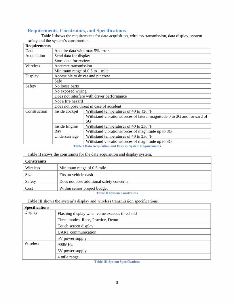
Societal and Environmental Impacts The current product on the formula car has an inadequate system for displaying and notifying the
driver of any problems. In the past this has led to catastrophic failures of the car. This puts the driver and
everyone around the car at risk. One year the motor was destroyed because it overheated and the driver
did not notice the temperature light was on. The new data display and acquisition system will eliminate
this problem because of the better designed notification and display features. The new system will make
the driver safer as well as anyone around the car safer too. The new system will consist of a more
aggressive notification system that will alert the driver if any of the monitored values exceed a certain
threshold, preventing any catastrophic failures from occurring. If a threshold is exceeded, then the driver
will be alerted and can then take appropriate actions to correct the problem. In the case when the engine
overheated and was destroyed, the new system could have prevented this and saved in repair cost from
this catastrophic failure. Not only will the driver be alerted of any problems, but the pit crew that is off
track will also receive notifications if a problem occurs. The pit crew will also see the same data as the
driver. The crew can then know to flag the driver down if there is a problem that the driver doesn’t notice.
Another positive attribute that the system will bring is that it will help contain spills of fluids (e.g. oil
spills). The system monitors the oil pressure, so if there is oil leaking the driver will notice from the
Amulet LCD in the car and can leave the track as soon as possible. Oil on the track is not good for the
environment and also can cause danger for other drivers, so it is important to try and eliminate this from
happening.
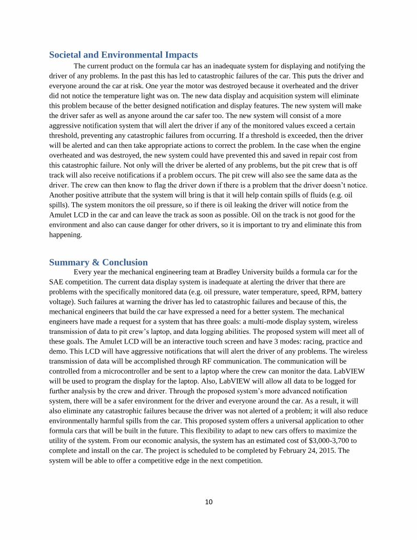
Summary & Conclusion Every year the mechanical engineering team at Bradley University builds a formula car for the
SAE competition. The current data display system is inadequate at alerting the driver that there are
problems with the specifically monitored data (e.g. oil pressure, water temperature, speed, RPM, battery
voltage). Such failures at warning the driver has led to catastrophic failures and because of this, the
mechanical engineers that build the car have expressed a need for a better system. The mechanical
engineers have made a request for a system that has three goals: a multi-mode display system, wireless
transmission of data to pit crew’s laptop, and data logging abilities. The proposed system will meet all of
these goals. The Amulet LCD will be an interactive touch screen and have 3 modes: racing, practice and
demo. This LCD will have aggressive notifications that will alert the driver of any problems. The wireless
transmission of data will be accomplished through RF communication. The communication will be
controlled from a microcontroller and be sent to a laptop where the crew can monitor the data. LabVIEW
will be used to program the display for the laptop. Also, LabVIEW will allow all data to be logged for
further analysis by the crew and driver. Through the proposed system’s more advanced notification
system, there will be a safer environment for the driver and everyone around the car. As a result, it will
also eliminate any catastrophic failures because the driver was not alerted of a problem; it will also reduce
environmentally harmful spills from the car. This proposed system offers a universal application to other
formula cars that will be built in the future. This flexibility to adapt to new cars offers to maximize the
utility of the system. From our economic analysis, the system has an estimated cost of $3,000-3,700 to
complete and install on the car. The project is scheduled to be completed by February 24, 2015. The
system will be able to offer a competitive edge in the next competition.

11
References [1] AC4790-200A [online]. Available FTP:
http://www.digikey.com/product-detail/en/AC4790-200A/AC4790-200A-ND/1844885
[2] STK 128 + Premium [online]. Available FTP: http://www.wvshare.com/product/STK128-Premium.htm
[3] NI LabVIEW Base Development System for Windows [online]. Available FTP:
http://sine.ni.com/nips/cds/view/p/lang/en/nid/1385
[4] STK-480272C [online]. Available FTP:
http://www.digikey.com/product-detail/en/STK-480272C/681-1016-ND/2001099?enterprise=44
[5] 11% off GEMstudio Pro Discount Promotion discount[online]. Available FTP:
http://freesafesoft.com/discount/GEMstudio_Pro-32323639392d35-coupon-code.php
[6] TTD25N-20-0300F-H [online]. Available FTP: http://www.automationdirect.com/adc/Shopping/Catalog/Process_Control_-a-
_Measurement/Temperature_Sensors_-a-_Transmitters/Temperature_Transmitters_(Integral_Sensor)/TTD25N-20-0300F-H
[7] (2013). 2014 student handbook [online]. Available FTP:
http://students.sae.org/cds/formulaseries/fsae/2014mis_handbook
[8] (2013). 2014 formula SAE michigan [online]. Available FTP:
http://students.sae.org/cds/formulaseries/fsae/fsaeprogram.pdf
[9] (2013). 2014 formula SAE michigan [online]. Available FTP:
http://students.sae.org/cds/formulaseries/fsae/fsaeprogram.pdf
[10] Mark Mikoff (2013). Formula SAE [online]. Available FTP:
http://cegt401.bradley.edu/projects/2013-2014/FSAE/BRADLEYMOTORSPORTS_files/Page299.htm
[9] Steve Brodkin (2011). Formula SAE [online]. Available FTP:
http://cegt401.bradley.edu/projects/2010-2011/FSAE/powertrain.html

12
Appendix
Gantt Chart
Appendix A Gantt Chart Full Version
Appendix A shows the full version of our project Gantt chart, previously mentioned in the proposal.

13
Expanded Expense Breakdown
Equipment Minimum Maximum
Screen $175 $220
Wireless transmission $130 $180
Microcontroller $40 $60
Temperature sensor $120 $150
Pressure sensor $120 $150
RPM sensor $120 $150
Vehicle speed sensor $120 $150
Software ( touch screen ) $500 $700
Software ( microcontroller ) $500 $700
Software ( remote display ) $1000 $1200
Total $2825 $3660 Appendix B Expanded Expense Breakdown