SAE AEROSPACE TECHNICAL REPORT STYLE...
48
SAE AEROSPACE TECHNICAL REPORT STYLE MANUAL AUGUST 2007 Downloaded from http://www.everyspec.com
Transcript of SAE AEROSPACE TECHNICAL REPORT STYLE...

SAE AEROSPACE TECHNICAL REPORT STYLE MANUAL
AUGUST 2007
Downloaded from http://www.everyspec.com

Downloaded from http://www.everyspec.com

SAE AEROSPACE TECHNICAL REPORT STYLE MANUAL This SAE Aerospace Technical Report Style Manual was prepared specifically for sponsors of SAE Aerospace Technical Reports (excluding Aerospace Material Specifications (AMS)). It contains all pertinent editorial and technical requirements for the preparation of SAE Aerospace Technical Reports, Aerospace Standards, Aerospace Recommended Practices, Aerospace Information Reports, and Aerospace Resource Documents (in inch-pound units/SI units versions). Editorial and technical requirements for the preparation of SAE AMS specifications can be found in the Manual for the Preparation of Aerospace Material Specifications. This Style Manual documents SAE's editorial policies and procedures. Rapidly changing technology has greatly increased the need for consistency and standardization in standards production. The purpose of the Style Manual is to improve consistency in SAE Aerospace Technical Reports and, thereby, enhance utilization of new technology. It is designed to formalize existing procedures and practices and from these, create a thorough SAE Aerospace Technical Report production policy that will enable SAE to meet the needs of present and future technology.
Revised August 2007
Downloaded from http://www.everyspec.com

SAE AEROSPACE TECHNICAL REPORT STYLE MANUAL
2
TABLE OF CONTENTS
1. SCOPE ...................................................................................................................................................................4 1.1 Purpose...................................................................................................................................................................4 2. REFERENCES.......................................................................................................................................................4 2.1 Applicable Documents............................................................................................................................................4 2.1.1 SAE Publications ....................................................................................................................................................4 2.1.2 ANSI Publications...................................................................................................................................................4 2.1.3 ASME Publications.................................................................................................................................................4 2.1.4 IEEE Publications ...................................................................................................................................................4 2.1.5 U.S. Government Publications...............................................................................................................................5 2.2 Applicable References ...........................................................................................................................................5 2.3 Definitions ...............................................................................................................................................................5 3. EDITORIAL REQUIREMENTS..............................................................................................................................6 3.1 Abbreviations and Symbols....................................................................................................................................7 3.2 Appendices .............................................................................................................................................................7 3.3 CAUTION Within Text ............................................................................................................................................8 3.4 Cross-References ..................................................................................................................................................8 3.5 Date (Issued/Revised)............................................................................................................................................9 3.6 Decimal Values.......................................................................................................................................................9 3.7 Equations................................................................................................................................................................9 3.8 Equivalency Statement...........................................................................................................................................9 3.9 Figures ....................................................................................................................................................................9 3.9.1 Numbering Figures.................................................................................................................................................9 3.10 Footnotes..............................................................................................................................................................10 3.11 Foreword...............................................................................................................................................................10 3.12 Headings...............................................................................................................................................................10 3.12.1 Front or Back Matter.............................................................................................................................................10 3.12.2 Section Headings .................................................................................................................................................11 3.12.3 Primary Paragraph Headings...............................................................................................................................11 3.12.4 Secondary and All Subsequent Headings...........................................................................................................11 3.13 Key Words ............................................................................................................................................................11 3.14 Listings..................................................................................................................................................................11 3.15 NOTE Within Text.................................................................................................................................................12 3.16 Notes Section .......................................................................................................................................................12 3.17 Numbers ...............................................................................................................................................................12 3.18 Prepared By Statement........................................................................................................................................13 3.19 Proprietary Names................................................................................................................................................13 3.20 Punctuation...........................................................................................................................................................13 3.20.1 Apostrophe ...........................................................................................................................................................13 3.20.2 Comma .................................................................................................................................................................13 3.20.3 Hyphen .................................................................................................................................................................14 3.20.4 Parentheses..........................................................................................................................................................14 3.20.5 Quotation Marks ...................................................................................................................................................14 3.21 Ranges..................................................................................................................................................................14 3.22 Rationale...............................................................................................................................................................15 3.23 References or Applicable Documents Section....................................................................................................15 3.24 Registered Trademarks........................................................................................................................................20 3.25 Revision Indicators ...............................................................................................................................................21 3.26 Sectional Arrangement.........................................................................................................................................21 3.27 Table of Contents .................................................................................................................................................22
Downloaded from http://www.everyspec.com

SAE AEROSPACE TECHNICAL REPORT STYLE MANUAL
3
3.28 Tables ...................................................................................................................................................................22 3.29 Tolerances ............................................................................................................................................................23 4. TECHNICAL REQUIREMENTS ..........................................................................................................................23 4.1 Abbreviations and Symbols..................................................................................................................................23 4.2 Artwork..................................................................................................................................................................23 4.3 Copyrighted Material ............................................................................................................................................23 4.4 Decimal Dimensioning..........................................................................................................................................23 4.5 Decimal Values.....................................................................................................................................................24 4.6 Dimensioning and Tolerancing Drawings............................................................................................................24 4.7 Figures ..................................................................................................................................................................24 4.8 General Considerations for SAE Aerospace Technical Reports ........................................................................24 4.8.1 Minimum Requirements .......................................................................................................................................24 4.8.2 Notice on All SAE Aerospace Technical Reports................................................................................................24 4.8.3 Patents and Copyrights ........................................................................................................................................25 4.8.4 Source of Supply ..................................................................................................................................................25 4.8.5 Test Materials .......................................................................................................................................................25 4.9 Mathematical Expressions ...................................................................................................................................25 4.10 Metrication ............................................................................................................................................................25 4.11 Numbering of SAE Aerospace Technical Reports ..............................................................................................25 4.11.1 Integrity of SAE Aerospace Technical Report Numbers.....................................................................................25 4.11.2 Prefixes .................................................................................................................................................................25 4.11.3 Revision Letters....................................................................................................................................................25 4.12 References to Other Documents .........................................................................................................................26 4.13 Registered Trademarks........................................................................................................................................26 4.14 Revisions to Existing SAE Aerospace Technical Reports ..................................................................................26 4.15 Shall or Should, Use of.........................................................................................................................................26 4.16 Titles of SAE Aerospace Technical Reports .......................................................................................................26 4.17 Procurement Specification QML/QPL Requirement ...........................................................................................27 5. TYPING REQUIREMENTS..................................................................................................................................27 5.1 General Requirements .........................................................................................................................................27 6. SAE AEROSPACE PARTS OR DESIGN STANDARD FORMATS...................................................................28 6.1 Parts Drawing Paper - First Page ........................................................................................................................28 6.2 Parts Drawing Paper - Second and Subsequent Pages.....................................................................................28 6.3 Editorial Requirements .........................................................................................................................................28 6.4 Typing Requirements ...........................................................................................................................................31 6.5 Technical Requirements ......................................................................................................................................31 6.5.1 Presentation..........................................................................................................................................................31 6.5.2 Graphical Representation ....................................................................................................................................33 6.5.3 Tabular Data .........................................................................................................................................................34 6.5.4 Part Number .........................................................................................................................................................37 6.5.5 Notes.....................................................................................................................................................................38 6.5.6 Additional Requirements for G-3 Aerospace Parts or Design Standards Only..................................................42 7. SAE AEROSPACE SUPPLEMENT.....................................................................................................................42 7.1 Supplement Balloting ...........................................................................................................................................42 7.2 Supplement Designations ....................................................................................................................................43 7.3 Instructions and Entry Format..............................................................................................................................43
Downloaded from http://www.everyspec.com
SAE AEROSPACE TECHNICAL REPORT STYLE MANUAL
4
1. SCOPE Section 1 will be designated as the SCOPE, which should briefly describe only the applicability of the document. The SCOPE should not be a summary of the contents of the document and should not be confused with the FOREWORD, RATIONALE, etc. All documents MUST have a SCOPE. 1.1 Purpose This paragraph is always numbered 1.1. It describes the purpose of your document. 2. REFERENCES Section 2 shall be designated REFERENCES. All pertinent and/or reference documents shall be listed here. These documents shall be grouped by publisher and information shall be provided on where to obtain the documents. SAE documents always go first, then the rest go in alphabetical order. 2.1 Applicable Documents The following publications form a part of this document to the extent specified herein. The latest issue of SAE publications shall apply. The applicable issue of other publications shall be the issue in effect on the date of the purchase order. In the event of conflict between the text of this document and references cited herein, the text of this document takes precedence. Nothing in this document, however, supersedes applicable laws and regulations unless a specific exemption has been obtained. 2.1.1 SAE Publications Available from SAE International, 400 Commonwealth Drive, Warrendale, PA 15096-0001, Tel: 877-606-7323 (inside USA and Canada) or 724-776-4970 (outside USA), www.sae.org AS1290 Graphic Symbols for Aircraft Hydraulic and Pneumatic Systems ARP1987 Titles SAE G-3 Committee Document Selection of TSB 003 Rules for SAE Use of SI (Metric) Units SAE Technical Standards Board Governance Policy 2.1.2 ANSI Publications Available from American National Standards Institute, 25 West 43rd Street, New York, NY 10036-8002, Tel: 212-642-4900, www.ansi.org ANSI/IEEE Std 260.1 American National Standard Letter Symbols for Units of Measurement ANSI/IEEE Std 260.3 American National Standard Mathematical Signs and Symbols for Use in Physical
Sciences and Technology ISO and Federal Specifications 2.1.3 ASME Publications Available from American Society of Mechanical Engineers, 22 Law Drive, P.O. Box 2900, Fairfield, NJ 07007-2900, Tel: 973-882-1170, www.asme.org
ASME Y14.38 Abbreviations and Acronyms 2.1.4 IEEE Publications Available from Institute of Electrical and Electronics Engineers, 445 Hoes Lane, Piscataway, NJ 08854-1331, Tel: 732-981-0060, www.ieee.org
Downloaded from http://www.everyspec.com
SAE AEROSPACE TECHNICAL REPORT STYLE MANUAL
5
IEEE/ASTM SI 10 Standard for Use of the International System of Units (SI): The Modern Metric System 2.1.5 U.S. Government Publications Available from the Document Automation and Production Service (DAPS), Building 4/D, 700 Robbins Avenue, Philadelphia, PA 19111-5094, Tel: 215-697-6257, http://assist.daps.dla.mil/quicksearch/ MIL-STD-961C Military Specifications and Associated Documents, Preparation of MIL-STD-100 Engineering Drawing Practices 2.2 Applicable References
The Chicago Manual of Style, 14th Edition, University of Chicago Press, Chicago, IL, 1993
United States Government Printing Office Style Manual 1984, (GPO), Superintendent of Documents, U.S. Government Printing Office, Washington, DC, 1984
Merriam Webster's Collegiate Dictionary, Tenth Edition 2.3 Definitions
AEROSPACE MATERIAL SPECIFICATIONS: Specifications that identify material and process specifications conforming to sound, established engineering and metallurgical practices in aerospace sciences and practices. These SAE Aerospace Technical Reports are published by the Technical Standards Division, SAE Headquarters with either the AMS (Aerospace Material Specification) or an MAM (Metric Aerospace Material Specification) prefix. AEROSPACE RESOURCE DOCUMENT: These Aerospace Technical Reports provide the reader with technical and non-technical information which may support a technical report. Examples include rationale reports, results of round robin or field testing, field data or empirical data, and compilations of industry research results, but may also report on state-of-the-art technology or be a technology needs-assessment. These documents shall have a maximum life of two years from adoption and cannot be revised or reaffirmed. The sponsoring Technical Committee can cancel this report by ballot at any time. Unlike the other Aerospace Technical Reports, ARDs are considered non-consensus documents and require only one level (Committee) approval. DESIGN SPECIFICATION: A specification that establishes the technical requirements for the design of: a. Part or assembly features b. Interface of parts or assemblies c. Mechanical, electrical, hydraulic, or pneumatic systems d. End item equipment DESIGN STANDARD DRAWING: An engineering drawing of an aerospace part feature or of an assembly of parts specifying the design requirements for interface dimensions, performance limits, etc. GRAPHIC SYMBOLS STANDARD: A standard containing a list of pictorial drawings that symbolize a device or part used in a given category of design engineering for developing schematic diagrams. INSPECTION STANDARD: A standard that establishes the acceptable limits for quality control of defects in materials, parts, or assemblies. Also, a standard that establishes the acceptance criteria for design features on parts or assemblies. INSTALLATION STANDARD: A standard that establishes the procedure for assembling parts or assemblies, including the preparation procedure, torque limits, precautions to be taken, inspection measures, etc. PARTS PROCUREMENT SPECIFICATION: A specification prepared to support an engineering drawing for parts or assemblies, describing technical requirements, tests, qualification requirements, quality control requirements, and packaging for purchased material.
Downloaded from http://www.everyspec.com
SAE AEROSPACE TECHNICAL REPORT STYLE MANUAL
6
PERFORMANCE STANDARD: A standard that establishes the minimum design parameters for the performance characteristics of: (1) design features, (2) parts or assemblies, (3) mechanical, electrical, hydraulic, or pneumatic systems, (4) accessory equipment, and (5) end item equipment. SAE INFORMATION REPORTS: SAE Aerospace Technical Reports that are compilations of engineering reference data or educational material useful to the technical community. SAE Aerospace Information Reports are published by the Technical Standards Division, SAE Headquarters with an AIR prefix. SAE RECOMMENDED PRACTICES: SAE Aerospace Technical Reports that are a documentation of practice, procedures, and technology that are intended as guides to standard engineering practice. Their content may be of a more general nature, or they may propound data that have not yet gained broad acceptance. This SAE Aerospace Technical Report type should emphasize the capabilities and limitations of the information contained therein. A technical committee preparing such a report may add an introductory note stating, "This SAE Recommended Practice is intended as a guide toward standard practice and is subject to change to keep pace with experience and technical advances." SAE Aerospace Recommended Practices are published by the Technical Standards Division, SAE Headquarters with an ARP (Aerospace Recommended Practice) or MAP (Metric Aerospace Recommended Practice) prefix. SAE STANDARDS: SAE Aerospace Technical Reports that are a documentation of broadly accepted engineering practices or specifications for a material, product, process, procedure, or test method. These SAE Aerospace Technical Reports are published by the Technical Standards Division, SAE Headquarters with an AS (Aerospace Standard) or MA (Metric Aerospace Standard) prefix. SPECIFICATION: A standard document prepared specifically to describe essential technical requirements for materials, processes, designs, performance, parts, installation, etc. to support engineering drawings and related publications. STANDARD PARTS DRAWING: An engineering procurement drawing of aerospace utility parts, specifying all design and manufacturing requirements for part configuration and dimensions, material, finish, part number, and identification marking, test, inspection, packaging, etc. SUPPLEMENT: A listing of associated detail standards citing the like numbered Parts Procurement Specification. No technical data shall be included in a supplement. Supplements are noted by a suffix. This suffix, without spacing, shall follow the Parts Procurement Specification number and shall be designated numerically; e.g. AS1424SUP1. TECHNICAL REPORT: An SAE Aerospace Technical Report approved and issued by the SAE Technical Standards Board. These SAE Aerospace Technical Reports include standards, specifications, recommended practices, information reports, and resource documents. TERMINOLOGY STANDARD: A standard containing a list of terms, related symbols, and definitions for a given category of design engineering. TEST STANDARD: A standard that establishes the method of performing a test, including apparatus required, test specimen preparation, sampling method, calibration, procedure, interpretation of results, and reporting results of test. 3. EDITORIAL REQUIREMENTS The requirements contained in this Section are of a strictly editorial nature. If, when submitted to SAE, an SAE Aerospace Technical Report does not comply, the Aerospace Standards Production Editor will edit the SAE Aerospace Technical Report to meet these requirements. Editorial requirements of a more technical nature are the responsibility of the preparing committee and are provided in Section 4.
Downloaded from http://www.everyspec.com

SAE AEROSPACE TECHNICAL REPORT STYLE MANUAL
7
Adherence to the requirements in this section is mandatory for all SAE Aerospace Technical Reports. Any exceptions to these requirements should be approved in advance by the technical committee chairperson and the responsible staff engineer. Editorial requirements in this section are presented alphabetically by subject heading. 3.1 Abbreviations and Symbols Abbreviations should be used sparingly, especially those SAE Aerospace Technical Reports used for procurement of parts. The chief purpose of SAE standard parts drawings and specifications is to express and convey engineering requirements in unmistakable terms to those who use them. In many cases these drawings and specifications are sent to suppliers and customers who must interpret them without having access to these abbreviations. The following rules shall apply: a. Common abbreviations and symbols are used without definition, e.g., 100 °C. b. The first time that an abbreviation or symbol of uncommon usage is used in the text, the full term shall be given
with the abbreviation or symbol following in parentheses. c. Where a sentence begins with an abbreviation consisting of several letters, and the sentence cannot be
rewritten, all the letters of the abbreviation shall be uppercase letters. d. For expressing the units in which quantities are measured, metric (SI) units have been prescribed by the SAE
Board of Directors and the SAE Technical Standards Board. Metric (SI) will be the only system used for expressing weights and measures without the approval of the individual councils/divisions.
The Aerospace Council of SAE recognizes several factors impacting the aerospace industry which are leading
to a change over to the SI metric system of measurements. The Aerospace Council further recognizes that the transition to the metric system will occur several years and that inch system aerospace items will be in manufacture and field service well into the 21st Century. Accordingly, the SAE Aerospace Council will continue the development of documents required for support of the inch system items in design, development, manufacture and/or field service.
e. SI and U.S. customary units in accordance with TSB 003 shall be used whenever the unit of measure follows a
number (i.e., "6 ft" but "measured in feet"). f. In accordance with TSB 003, periods are omitted after abbreviations for units of measure. g. Most Latin abbreviations (i.e., e.g., etc.) retain the periods, however, if in doubt, check Webster's Dictionary. h. Do not use an "s" to form a plural of an abbreviation (i.e., 5 in not 5 ins). i. The ° is not used when referring to angles. Spell out degree or degrees. 3.2 Appendices 3.2.1 Appendices shall be identified by a letter (i.e., Appendix A) and title and centered on the page. See
example:
APPENDIX A - TITLE 3.2.2 Letters shall be assigned sequentially from their first mention in the text. All appendices shall be mentioned
in text. 3.2.3 All appendices shall be located at the end of the SAE Aerospace Technical Report.
Downloaded from http://www.everyspec.com

SAE AEROSPACE TECHNICAL REPORT STYLE MANUAL
8
3.2.4 The first section of the appendix shall be numbered A.1 with subsequent paragraphs numbered as A.1.1, A.1.1.1, A.1.2, etc. The second section shall be A.2; the third, A.3, etc.
3.2.5 Figures, tables, and equations within an appendix shall be numbered FIGURE A#, TABLE A#, and Eq. A#
(i.e., FIGURE A1). Footnotes within appendices shall carry-over the sequential numbering from the text. 3.3 CAUTION Within Text Cautions shall be formatted as follows: CAUTION: The word Caution shall be all caps and followed by a colon. The text of the caution shall be indented to
align with the first word of the caution text. 3.4 Cross-References 3.4.1 References to parts within the SAE Aerospace Technical Report shall only be used to clarify a specified
requirement, and to avoid inconsistencies or unnecessary repetition. Cross-references shall be used rather than repetition since repetition involves the risk of error and increases the length of the SAE Aerospace Technical Report.
3.4.2 All references to text, tables, figures, and SAE Aerospace Technical Reports shall be verified as to their
accuracy and that they are in fact included as referenced. 3.4.3 References to Parts of the Text Where the reference is to a specific section, appendix, or a specific paragraph number use the following form without titles: a. (see Section 3) b. (see Appendix A) c. (see 3.4) 3.4.4 References to Tables and Figures Every table and figure shall be referred to in the text with a suitable explanation given as to its use. Reference shall not be made to the page on which a table or figure appears. Use a form similar to one of the following: a. specified in Table 2 b. (see Table 2) c. as illustrated in Figure 3 d. (see Figure 3) 3.4.5 References to Other Technical Reports Reference to another document shall be made only to the document number, omitting its title. The complete reference, with document number, title, and ordering facility, is given in Section 2. References to particular paragraphs of other documents shall be avoided because of the risk of such references becoming invalid as a result of revision. The particular portion of the document to be referenced shall be referred to by title, method number, identified requirement, or other definitive designation.
Downloaded from http://www.everyspec.com

SAE AEROSPACE TECHNICAL REPORT STYLE MANUAL
9
3.5 Date (Issued/Revised) The date(s) shall be specified numerically with the year and the month. Example: 1994-04 3.6 Decimal Values See Section 3.17. 3.7 Equations 3.7.1 Each equation or group of equations shall be identified by number. Any equation or group of equations,
separated with intervening text from the preceding equation, must have a new identifying number. 3.7.2 The equation number shall be preceded by "Eq." and enclosed in parentheses. Each equation shall be
centered within the margins. See example: x= (a x b) + (c-d) (Eq. 1) 3.7.3 The format for defining terms within an equation is as follows: where: x = The value to be determined a = 3 b = 1 a x y = n d = 7.5 To create an equation: Insert, Object, Microsoft Equation 3.0. Do not use MathType to create equations because it
is not compatible with all systems. 3.8 Equivalency Statement 3.8.1 Equivalency statements shall be one line and included in the title block but separate and distinct from the
title. If further reference is required, the title block comment shall refer to the appropriate section in the document where a full reference description can be given.
3.9 Figures 3.9.1 Numbering Figures Every figure shall be consecutively numbered with Arabic numerals in order of their reference in the text. Every Appendix figure shall be consecutively numbered in order of their reference in the Appendix. 3.9.2 All figures shall be mentioned in the text. With few exceptions, the figures will appear as soon after the first
mention as the layout will permit. 3.9.3 Figures in tables shall carry over the sequential numbering of figures from the text. 3.9.4 The figure caption, including a short, descriptive title shall be placed below the figure. The word FIGURE in
uppercase letters shall precede the Arabic numeral which is followed by a space and then a hyphen. The words in the title shall be uppercase letters. Figure captions shall appear outside of artwork border. See example:
FIGURE 12 - TITLE
Downloaded from http://www.everyspec.com

SAE AEROSPACE TECHNICAL REPORT STYLE MANUAL
10
3.9.5 If it is necessary to present a figure in parts, figures should be broken down as follows:
FIGURE 1A - TITLE FIGURE 1B - TITLE FIGURE 1 - TITLE
3.10 Footnotes 3.10.1 Footnotes shall be designated by a superscripted Arabic number and shall be numbered consecutively
throughout the text. 3.10.2 Footnotes shall appear at the bottom of the page on which the footnote is designated. To insert a footnote: Insert, Reference, Footnote, Insert. ______________________________ 1 Footnotes are presented in this format. 3.10.3 Footnotes in tables are described in 3.28.5. 3.11 Foreword At the discretion of the preparing committee, SAE Aerospace Technical Reports may contain a FOREWORD. Pertinent information that is not part of the technical text shall be included here. The type of text that shall be in the FOREWORD includes: a. Relationship of the SAE Aerospace Technical Report to other documents (i.e., ISO, ANSI, etc.) b. History, background, and any other introductory material 3.12 Headings Heading styles and formats are illustrated in Figure 1 and described in the following paragraphs.
FRONT OR BACK MATTER xxxxxxxxxxxxxxxxxxxxxxxxxxxxxxxxxxxxxxxxxxxxxxxxxxxxxxxxxxxxxxxxxxxxxxxxxxxxxxxxxxxxxxxxxxxxxxxxxxxxxx 1. SECTION HEADING xxxxxxxxxxxxxxxxxxxxxxxxxxxxxxxxxxxxxxxxxxxxxxxxxxxxxxxxxxxxxxxxxxxxxxxxxxxxxxxxxxxxxxxxxxxxxxxxxxxxxx x.x Primary Paragraph xxxxxxxxxxxxxxxxxxxxxxxxxxxxxxxxxxxxxxxxxxxxxxxxxxxxxxxxxxxxxxxxxxxxxxxxxxxxxxxxxxxxxxxxxxxxxxxxxxxxxx x.x.x Secondary or Subsequent Heads xxxxxxxxxxxxxxxxxxxxxxxxxxxxxxxxxxxxxxxxxxxxxxxxxxxxxxxxxxxxxxxxxxxxxxxxxxxxxxxxxxxxxxxxxxxxxxxxxxxxxx
FIGURE 1 - HEADING STYLES 3.12.1 Front or Back Matter This material includes the Rationale, Foreword, Table of Contents, Appendices, Indices, etc. The heading is all caps and centered as shown in Figure 1.
Downloaded from http://www.everyspec.com

SAE AEROSPACE TECHNICAL REPORT STYLE MANUAL
11
3.12.2 Section Headings All section headings (i.e., 1. SCOPE, 2. REFERENCES) shall be flush left and all caps. 3.12.3 Primary Paragraph Headings All primary paragraph headings (x.x paragraph numbers) shall be flush left with an initial cap for each major word in the title. 3.12.4 Secondary and All Subsequent Headings Headings for secondary (x.x.x paragraph numbers) and all subsequent (x.x.x.+ paragraph numbers) shall be flush left with an initial cap for each major word in the title. If there is not a title, text will begin on same line as paragraph number. 3.13 Key Words 3.13.1 The capability of SAE Aerospace Technical Reports to be searched electronically and be accessible via a
database, it is important that significant terms (those in-text and not included in-text) be listed in the NOTES Section under the heading of "Key Words."
The significant terms shall be listed in a string, separated by commas, and typed in lowercase letters. See
example: Aerospace, engines, icing, jet engines, propulsion 3.14 Listings 3.14.1 The preferred method for presenting a list is with each item in the list identified by a lowercase letter. This
type of listing is set flush left. The first letter of each entry is capitalized. All carry-over lines align with the first letter of that entry. See example:
a. The first item in the list 1. First subdivision; any carryover portion of the text will be aligned as is indicated here (a) Second subdivision b. The second item in the list c. Etc. 3.14.2 All entries within a list should parallel each other grammatically: if one entry is a complete sentence, all
entries should be; if the verb tense is active in one entry, it should be active in all entries. 3.14.3 In-text listings that are not set off from the text with double spaces shall be presented in the following
manner: Typical data included (1) rpm, (2) mpg, and (3) mph.
Downloaded from http://www.everyspec.com

SAE AEROSPACE TECHNICAL REPORT STYLE MANUAL
12
3.15 "NOTE" Within Text Notes shall be formatted as follows: NOTE: The word Note shall be all caps and followed by a colon. The text of the Note shall be indented to align
with the first word of the Note text. 3.16 Notes Section The last numbered section shall be NOTES. This section shall contain the (R) statement for revisions and the Key Words paragraph and as applicable, statement of patentability and other relevant information. 3.17 Numbers 3.17.1 All numbers between one and ten, inclusive, should be written out unless followed by a unit of measure
(i.e., cm, in, etc.). All numbers greater than ten should be expressed in numerical form, regardless of what they precede. All numbers followed by a unit of measure shall be expressed in numerical form unless it begins a sentence.
However, the following exceptions shall apply: a. Never begin a sentence with a numeral. Preferably, the sentence should be restructured to avoid
writing out a number larger than ten. If absolutely essential to begin a sentence with a number, it should be spelled out.
b. When there is more than one number within a sentence, they should both appear in the same form. 3.17.2 The decimal sign shall be the decimal point (dot or .) for both inch-pound and SI units. 3.17.3 Numbers less than one expressed as decimals must always be preceded by a zero before the decimal point
(i.e., 0.25) in text and nonparts drawing tables. 3.17.4 A cross (x), not a center dot (.), shall be used to indicate multiplication of numerical values. See example: 1.8 x 10⁻³ and not 1.8 . 10-3 3.17.5 For groups of terms in a formula, parentheses, brackets, or braces are used to indicate multiplication. 3.17.6 When referring to numerical values of physical quantities, the Arabic numerals are followed by the symbol
for the unit. A space should be left between the numerical value and the unit symbol. Exception: No space is left between the numerical value and the symbols for degree, minute, and second of plane angles.
3.17.7 Tolerances shall be indicated in the following manner in the text: a. 20 °C ± 5 °C b. 250 °F ± 10 °F c. 1.25 in ± 0.01 in d. 80 mm ± 2 mm e. 100 m ± 5 m
Downloaded from http://www.everyspec.com

SAE AEROSPACE TECHNICAL REPORT STYLE MANUAL
13
Where unequal tolerances are involved, express min and max values in lieu of tolerancing in the text, as follows:
a. 5 to 12 in b. 19 to 22 °C c. 63 to 68% Refer to ASME Y14.5M for rules on dimensioning and tolerancing drawings. 3.18 Prepared By Statement 3.18.1 All SAE Aerospace Technical Reports shall contain a "JURISDICTION" statement. This statement shall not
have a paragraph number and shall be in all caps and centered across the bottom of the last page before any appendices. See example:
PREPARED BY SAE SUBCOMMITTEE AE-8C2, TERMINATING DEVICES OF
COMMITTEE AE-8, AEROSPACE ELECTRICAL/ELECTRONIC DISTRIBUTION SYSTEMS 3.19 Proprietary Names The use of proprietary rules shall conform to TSB Governance Policy which states: ..."No proprietary names or trademarks shall be used in SAE Aerospace Technical Reports without written permission of the owner together with a generic description of the product sufficient to enable a user to conform to the SAE Aerospace Technical Report without resort to such proprietary product." It is the sponsor's responsibility to recognize proprietary information. 3.20 Punctuation 3.20.1 Apostrophe Apostrophes in acronyms or dates shall not be used to indicate plurals (i.e., DNAs and 1990s not DNA's or 1920's). In general, inanimate objects cannot "own" anything (i.e., the world population not the world's population). 3.20.2 Comma Grammatical rules as itemized in the Chicago Manual of Style shall apply. The placement of a comma, however, is occasionally arbitrary -- a matter of personal preference and an enigmatic quality called "readability." The placement of commas is mainly a matter of good judgment and ease of reading shall be of foremost importance. In addition to the grammatical rules contained in the Chicago Manual of Style, the following rules shall apply to commas: a. In a series of three or more, use a comma after each element (apples, oranges, and pears). b. Do not place a comma after etc. when it is used as an element of a series. Simply place one before it (apples,
oranges, etc.) c. Use a comma before and after "i.e." and "e.g." Parentheses may be substituted for the comma that precedes the
word (i.e.). d. Use a comma before "respectively" if it falls at the end of a sentence. Use commas before and after if it falls in
the middle of a sentence. e. Use a comma in numerals containing five or more digits (e.g., 20,000; 200,000; etc.).
Downloaded from http://www.everyspec.com
SAE AEROSPACE TECHNICAL REPORT STYLE MANUAL
14
3.20.3 Hyphen Sound editorial judgment and readability shall be the guideposts in the use of hyphens. As always, Webster's Dictionary shall be the final authority on the use of hyphens. Some specific rules of hyphenation are included here: a. Hyphens should be used only when absolutely necessary for clarity. b. In all instances, Webster's Dictionary is our accepted authority. Unless there is a compelling reason to deviate,
follow the form indicated there, even if the specific example is not included therein (particularly in the case of double letters, i.e., anti-influenza and reestablish).
c. Words preceded by pre, post, re, non, semi, anti, etc. are generally one word, with no hyphen between the prefix
and the following word. d. Words preceded by self, cross, or well are generally hyphenated if they modify a noun. If they are not modifying
a noun, they are generally left as two words. e. Adverbs ending in "ly" are not hyphenated (i.e., naturally occurring). f. Compound numbers and fractions are hyphenated (i.e., twenty-three and one-fourth). 3.20.4 Parentheses In addition to the rules in Chicago Manual of Style, the following rules are specific to SAE or are provided for ease of reference: a. No punctuation mark should directly precede parentheses unless the parenthetical material is a complete
sentence and treated as such. b. If necessary to place parentheses inside of parentheses, the outermost pair becomes brackets. c. Parentheses should be used to set off numbers in a series presented in text [i.e., (1) apples, (2) oranges, and (3)
pears]. 3.20.5 Quotation Marks The rules governing quotation marks given in the Chicago Manual of Style shall apply. Rules frequently violated or specific to SAE are as follows: a. Closing quotation marks when citing an actual quotation always follow periods and commas. Colons,
semicolons, exclamation points, and question marks are placed outside of the closing quotation marks unless they are part of the quoted matter.
b. The use of quotation marks for emphasis or to indicate a term, slang, etc. is imprecise and should be
discouraged. However, if quotation marks are used for emphasis, all punctuation should appear after the closing quotation mark.
3.21 Ranges 3.21.1 In text, use "to" to indicate a range. Example: Pour 2 to 4 L of fluid 3.21.2 In tables and figures, a closed hyphen shall be used to indicate a range (2-4 L). If either number is preceded
by a minus, use "to" and be consistent within that table.
Downloaded from http://www.everyspec.com

SAE AEROSPACE TECHNICAL REPORT STYLE MANUAL
15
3.21.3 In a range, the unit follows only the last number if the units are the same (i.e., 3 to 4 cm). 3.22 Rationale Aerospace documents must contain a RATIONALE. The RATIONALE will appear as an unnumbered paragraph before 1. SCOPE. The RATIONALE defines the need for developing a standard or the factor(s) which prompt a revision. 3.23 References or Applicable Documents Section 3.23.1 Section 2 shall always be either REFERENCES or APPLICABLE DOCUMENTS. Section 2 shall include, as
required, paragraphs for Applicable Documents, Related Publications, Definitions, Terminology, and Symbols.
3.23.2 If the only references contained within this section are documents, this section shall be titled APPLICABLE
DOCUMENTS and subsequent paragraphs shall be numbered accordingly. If there are nondocument references or definitions, etc. provided in this section, the section shall be titled REFERENCES with Applicable Documents becoming the first primary paragraph in the section.
If there are no references, the following statement shall be included: 2. REFERENCES There are no referenced publications specified herein. 3.23.3 Applicable Documents Primary paragraph 2.1 shall be Applicable Documents. All pertinent and/or reference publications shall be listed here. These publications shall be grouped by publisher and information shall be provided on obtaining the publications. The format for presenting this paragraph is as follows: 2.1 Applicable Documents The following publications form a part of this document to the extent specified herein. The latest issue of SAE publications shall apply. The applicable issue of other publications shall be the issue in effect on the date of the purchase order. In the event of conflict between the text of this document and references cited herein, the text of this document takes precedence. Nothing in this document, however, supersedes applicable laws and regulations unless a specific exemption has been obtained. 2.1.1 SAE Publications
Available from SAE International, 400 Commonwealth Drive, Warrendale, PA 15096-0001, Tel: 877-606-7323 (inside USA and Canada) or 724-776-4970 (outside USA), www.sae.org. ARP1234 Title AIR2345 Title 2.1.2 ASTM Publications
Available from ASTM International, 100 Barr Harbor Drive, P.O. Box C700, West Conshohocken, PA 19428-2959, Tel: 610-832-9585, www.astm.org. ASTM A 1234 Title
Downloaded from http://www.everyspec.com

SAE AEROSPACE TECHNICAL REPORT STYLE MANUAL
16
2.1.3 U.S. Government Publications
Available from the Document Automation and Production Service (DAPS), Building 4/D, 700 Robbins Avenue, Philadelphia, PA 19111-5094, Tel: 215-697-6257, http://assist.daps.dla.mil/quicksearch/. 3.23.4 Commonly referenced organizations and their addresses include the following: AECMA PUBLICATIONS Available from National Standards Association, 1200 Quince Orchard Boulevard, Gaithersburg, MD 20878, www.aecma.org. AIA PUBLICATIONS Available from Aerospace Industries Association, 1000 Wilson Boulevard, Suite 1700, Arlington, VA 22209-3928, Tel: 703-358-1000, www.aia-aerospace.org. AISI PUBLICATIONS Available from American Iron and Steel Institute, 1140 Connecticut Avenue, NW, Suite 705, Washington, DC 20036, Tel: 202-452-7100, www.steel.org. ANSI PUBLICATIONS Available from American National Standards Institute, 25 West 43rd Street, New York, NY 10036-8002, Tel: 212-642-4900, www.ansi.org. API AND IP PUBLICATIONS Available from American Petroleum Institute, 1220 L Street, NW, Washington, DC 20005-4070, Tel: 202-682-8000, http://api-ec.api.org. ARINC PUBLICATIONS Available from ARINC, 2551 Riva Road, Annapolis, MD 21401. www.arinc.com. ASME PUBLICATIONS Available from American Society of Mechanical Engineers, 22 Law Drive, P.O. Box 2900, Fairfield, NJ 07007-2900, Tel: 973-882-1170, www.asme.org. ASQ PUBLICATIONS Available from American Society for Quality, 600 North Plankinton Avenue, Milwaukee, WI 53203, Tel: 800-248-1946 (United States or Canada)) or +1-414-272-8575 (International), www.asq.org. ASTM PUBLICATIONS Available from ASTM International, 100 Barr Harbor Drive, P.O. Box C700, West Conshohocken, PA 19428-2959, Tel: 610-832-9585, www.astm.org.
ATA PUBLICATIONS
Available from Air Transport Association of America, Inc., 1301 Pennsylvania Avenue, NW, Suite 1100, Washington, DC 20004-1707, Tel: 202-626-4000, www.airlines.org.
Downloaded from http://www.everyspec.com
SAE AEROSPACE TECHNICAL REPORT STYLE MANUAL
17
AWS PUBLICATIONS Available from American Welding Society, 550 NW LeJeune Road, Miami, FL 33126, Tel: 1-800-443-9353, www.aws.org.
CODE OF FEDERAL REGULATIONS (CFR)
Available from the United States Government Printing Office, 732 North Capitol Street, NW, Washington, DC 20401, Tel: 202-512-0000, www.gpoaccess.gov.
CIE PUBLICATIONS Available from Commission Internationale de l'Eclairage, CIE Central Bureau, Kegelgasse 27, A-1030 Wien, Austria, Tel: +43-1-714-31-87-0, www.cie.co.at. CSA PUBLICATIONS Available from CSA International, 178 Rexdale Boulevard, Toronto, Ontario, Canada M9W 1R3, Tel: 416-747-4000, www.csa-international.org.
EASA PUBLICATIONS Available from European Aviation Safety Agency, Postfach 10 12 53, D-50452 Koeln, Germany, Tel: +49-221-8999-000, www.easa.eu.int.
ECA PUBLICATIONS Available from ECA, 2500 Wilson Boulevard, Arlington, VA 22201, Tel: 703-907-8024, www.ec-central.org.
EIA PUBLICATIONS Available from Electronic Industries Alliance, 2500 Wilson Boulevard, Arlington, VA 22201-3834, Tel: 703-907-7500, www.eia.org. EUROPEAN AVIATION REGULATIONS Available from European Aviation Safety Agency, Otto Platz 1, Postfach 101253, D-50452, Cologne, Germany, www.easa.eu.int.
EUROPEAN UNION PUBLICATIONS
Available from European Aviation Safety Agency, Postfach 10 12 53, D-50452 Koeln, Germany, Tel: +49-0-221-8999-0000, www.easa.eu.int. FAA PUBLICATIONS Available from Federal Aviation Administration, 800 Independence Avenue, SW, Washington, DC 20591, Tel: 866-835-5322, www.faa.gov.
FAR PUBLICATIONS Available from Federal Aviation Administration, 800 Independence Avenue, SW, Washington, DC 20591, Tel: 866-835-5322, www.faa.gov.
Downloaded from http://www.everyspec.com

SAE AEROSPACE TECHNICAL REPORT STYLE MANUAL
18
IATA PUBLICATIONS Available from International Air Transport Association, Publications Assistant, 800 Place Victoria, P.O. Box 113, Montreal, Quebec H4Z 1M1, Canada, Tel: 1-514-874-0202, www.iata.org.
ICAO PUBLICATIONS Available from ICAO, Document Sales Unit, 999 University Street, Montreal, Quebec H3C 5H7 Canada, Tel: +1-514-954-8022, http://icaodsu.openface.ca/mainpage.ch2. IEC PUBLICATIONS Available from International Electrotechnical Commission, 3, rue de Varembe, P.O. Box 131, 1211 Geneva 20, Switzerland, Tel: +44-22-919-02-11, www.iec.ch. IEEE PUBLICATIONS Available from Institute of Electrical and Electronics Engineers, 445 Hoes Lane, Piscataway, NJ 08854-1331, Tel: 732-981-0060, www.ieee.org. IPC-ASSOCIATION CONNECTING ELECTRONICS INDUSTRIES Available from IPC, 3000 Lakeside Drive, Bannockburn, IL 60015, Tel: 847-597-2862, www.ipc.org. ISO PUBLICATIONS Available from American National Standards Institute, 25 West 43rd Street, New York, NY 10036-8002, Tel: 212-642-4900, www.ansi.org. or if using the Switzerland address: Available from International Organization for Standardization, 1, rue de Varembe, Case postale 56, CH-1211 Geneva 20, Switzerland, Tel: +41-22-749-01-11, www.iso.org. NACA REPORTS Available from National Technical Information Service, 5285 Port Royal Road, Springfield, VA 22161. www.ntis.gov. NACE PUBLICATIONS Available from NACE International, 1440 South Creek Drive, Houston, TX 77084-4906, Tel: 1-800-797-6223, www.nace.org. NAS PUBLICATIONS Available from Aerospace Industries Association, 1000 Wilson Boulevard, Suite 1700, Arlington, VA 22209-3928, Tel: 703-358-1000, www.aia-aerospace.org. NASA PUBLICATIONS Available from NASA, Documentation, Marshall Space Flight Center, AL 35812, www.nas.nasa.gov. NASA KSC PUBLICATIONS Available from NASA, John F. Kennedy Space Center, Mail Code: Library-D, Kennedy Space Center, FL 32899, www.ksc.nasa.gov.
Downloaded from http://www.everyspec.com

SAE AEROSPACE TECHNICAL REPORT STYLE MANUAL
19
NATIONAL CONFERENCE OF STANDARDS LABORATORIES (NCSL) National Conference of Standards Laboratories, 2995 Wilderness Place, Suite 107, Boulder, CO 80301-5404, Tel: 303-440-3339, www.ncsli.org. NEMA PUBLICATIONS Available from National Electrical Manufacturers Association, 1300 North 17th Street, Suite 1752, Roslyn, VA 22209, Tel: 703-841-3200, www.nema.org. NFPA PUBLICATIONS Available from National Fire Protection Agency, 1 Batterymarch Park, Quincy, MA 02169-7471, Tel: 617-770-3000, www.nfpa.org.
NIST PUBLICATIONS
Available from National Institute of Standards and Technology, 100 Bureau Drive, Stop 1070, Gaithersburg, MD 20899-1070, Tel: 301-975-6478, www.nist.gov.
OSHA PUBLICATIONS Available from U.S. Department of Labor/OSHA, OSHA Publications, P.O. Box 37535, Washington, DC 20013-7535, Tel: 202-693-1888, www.osha.gov/pls/publications/pubindex.list. PRI PUBLICATIONS Available from Performance Review Institute, 161 Thorn Hill Road, Warrendale, PA 15086-7527, Tel: 724-772-1616, www.pri-network.org. PUBLIC HEALTH SERVICE PUBLICATIONS Available from U.S. Department of Health and Human Services, 200 Independence Avenue, Washington, DC 20201, Tel: 877-696-6775, www.os.dhhs.gov. RTCA PUBLICATIONS Available from Radio Technical Commission for Aeronautics Inc., 1828 L Street, NW, Suite 805, Washington, DC 20036, Tel: 202-833-9339, www.rtca.org. SAE PUBLICATIONS Available from SAE International, 400 Commonwealth Drive, Warrendale, PA 15096-0001, Tel: 877-606-7323 (inside USA and Canada) or 724-776-4970 (outside USA), www.sae.org. STEEL TANK INSTITUTE PUBLICATIONS Available from Steel Tank Institute, 570 Oakwood Road, Lake Zurich, IL 60047, Tel: 847-438-8265, www.steeltank.com.
TIA PUBLICATIONS
Available from Telecommunications Industry Association, 2500 Wilson Boulevard, Suite 300, Arlington, VA 22201, Tel: 703-907-7700, www.tiaonline.org/standards/.
Downloaded from http://www.everyspec.com

SAE AEROSPACE TECHNICAL REPORT STYLE MANUAL
20
UL PUBLICATIONS Available from Underwriters Laboratories Inc., 333 Pfingsten Road, Northbrook, IL 60062-2096, Tel: 847-272-8800, www.ul.com. U.S. GOVERNMENT Available from the Document Automation and Production Service (DAPS), Building 4/D, 700 Robbins Avenue, Philadelphia, PA 19111-5094, Tel: 215-697-6257, http://assist.daps.dla.mil/quicksearch/. 3.23.5 Related Publications At the discretion of the preparing committee, informational references may be included as a primary paragraph in Section 2 and labeled as Related Publications with the following wording: The following publications are provided for information purposes only and are not a required part of this SAE Aerospace Technical Report. 3.23.6 Definitions All definitions shall be provided in a primary paragraph of Section 2 in the following format: x.x Definitions TERM: The word that is to be defined xxxxxxxxxxxxxxxxxxxxxxxxxxxxxxxxxxxxxxxxxxxxxxxxxxxxxxxxxxxxxxxxxxxx xxxxxxxxxxxxxxxxxxxxxxxxxxxxxxxxxxxxxxxxxxxxxxxxxxxxxxxxxxxxxxxxxxxxxxxxxxxxxxxxxxxxxxxxxxxxxxxxxxxxxx The term to be defined is all caps and the definition is dictionary-style (i.e., the term is not repeated and the definition is written in phrases). 3.23.7 Symbols All symbols shall be provided in a primary paragraph of Section 2. 3.23.8 Terminology Terminology shall be provided in a primary paragraph of Section 2. 3.24 Registered Trademarks 3.24.1 Please refer to TSB Governance Policy for guidance. 3.24.2 The word preceding the ® shall begin with a capital letter. The presence of a capital letter may be an
indication that the word is a registered trademark.
Downloaded from http://www.everyspec.com
SAE AEROSPACE TECHNICAL REPORT STYLE MANUAL
21
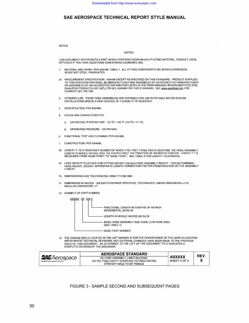
3.25 Revision Indicators To indicate changes from the previous revision, use the change bar ( I ). If the entire SAE Aerospace Technical Report has been rewritten, the (R) symbol shall be placed directly to the left of the title. When utilizing the ( I ) or (R) symbol, the following statement will be included in the Notes section:
The change bar ( I ) located in the left margin is for the convenience of the user in locating areas where technical revisions, not editorial changes, have been made to the previous issue of this document. An (R) symbol to the left of the document title indicates a complete revision of the document.
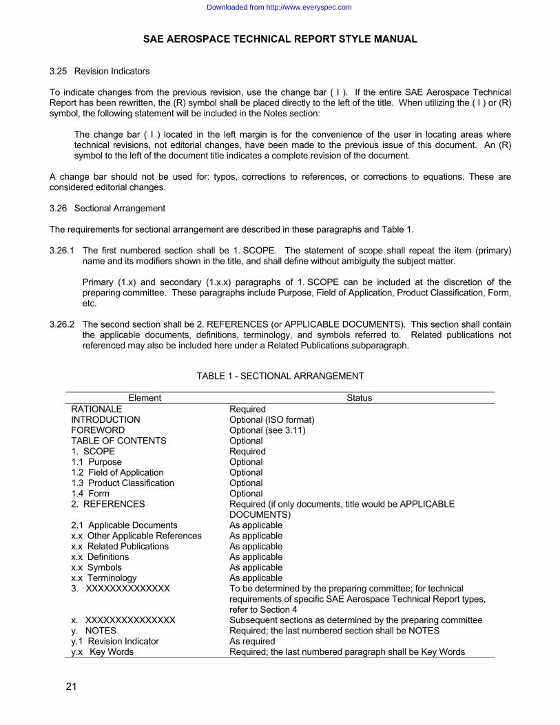
A change bar should not be used for: typos, corrections to references, or corrections to equations. These are considered editorial changes. 3.26 Sectional Arrangement The requirements for sectional arrangement are described in these paragraphs and Table 1. 3.26.1 The first numbered section shall be 1. SCOPE. The statement of scope shall repeat the item (primary)
name and its modifiers shown in the title, and shall define without ambiguity the subject matter. Primary (1.x) and secondary (1.x.x) paragraphs of 1. SCOPE can be included at the discretion of the
preparing committee. These paragraphs include Purpose, Field of Application, Product Classification, Form, etc.
3.26.2 The second section shall be 2. REFERENCES (or APPLICABLE DOCUMENTS). This section shall contain
the applicable documents, definitions, terminology, and symbols referred to. Related publications not referenced may also be included here under a Related Publications subparagraph.
TABLE 1 - SECTIONAL ARRANGEMENT
Element Status RATIONALE Required INTRODUCTION Optional (ISO format) FOREWORD Optional (see 3.11) TABLE OF CONTENTS Optional 1. SCOPE Required 1.1 Purpose Optional 1.2 Field of Application Optional 1.3 Product Classification Optional 1.4 Form Optional 2. REFERENCES Required (if only documents, title would be APPLICABLE
DOCUMENTS) 2.1 Applicable Documents As applicable x.x Other Applicable References As applicable x.x Related Publications As applicable x.x Definitions As applicable x.x Symbols As applicable x.x Terminology As applicable 3. XXXXXXXXXXXXXX To be determined by the preparing committee; for technical
requirements of specific SAE Aerospace Technical Report types, refer to Section 4
x. XXXXXXXXXXXXXXX Subsequent sections as determined by the preparing committee y. NOTES Required; the last numbered section shall be NOTES y.1 Revision Indicator As required y.x Key Words Required; the last numbered paragraph shall be Key Words
Downloaded from http://www.everyspec.com

SAE AEROSPACE TECHNICAL REPORT STYLE MANUAL
22
3.27 Table of Contents 3.27.1 At the discretion of the preparing committee, an automated Table of Contents may be included. See
example:
TABLE OF CONTENTS 1. SCOPE ..................................................................................................... 2. REFERENCES......................................................................................... 3. TECHNICAL REQUIREMENTS.............................................................. 3.1 Icing Definitions ........................................................................................ 3.1.1 Icing Intensity............................................................................................ APPENDIX A TITLE........................................................................................................ FIGURE 1 TITLE........................................................................................................ TABLE 1 TITLE........................................................................................................ 3.28 Tables 3.28.1 Numbering Tables Every table shall be consecutively numbered with Arabic numerals in order of their reference in the text. Every Appendix table shall be consecutively numbered in order of their reference in the Appendix. 3.28.2 All tables shall be mentioned in the text. With few exceptions, the tables will appear as soon after the first
mention as the layout will permit. 3.28.3 The table caption including a short, descriptive title shall be placed above the table. The word TABLE in
uppercase letters shall precede the Arabic numeral which is followed by a space hyphen space. Each word of the title shall be in uppercase letters. See example:
TABLE 1 - TITLE 3.28.4 Microsoft Office's table feature should be used for creating all tables (in both Part Standards documents and
Nonparts Standards documents. 3.28.5 For clarity, double spacing between every three rows of entries is desirable. 3.28.6 Footnotes in Tables a. Footnotes to tables should be positioned single spaced within the table. b. Numbering of footnotes is consecutive within each table in order of appearance reading the table from
left-to-right. c. The line above footnotes is not utilized. d. In tables where a superscripted number identifying a footnote might be mistaken for an exponent, the footnote
shall be followed by a closing parenthesis. e. Tables may have notes that are unnumbered and presented under the heading of Notes.
Downloaded from http://www.everyspec.com

SAE AEROSPACE TECHNICAL REPORT STYLE MANUAL
23
3.28.7 If it is necessary to present a table in parts or if you have inch-pound unit/SI unit versions, tables should be broken down as follows:
TABLE 2 - TITLE
TABLE 2A - TITLE, INCH-POUND UNITS TABLE 2B - TITLE, SI UNITS
3.29 Tolerances See Section 3.17. 4. TECHNICAL REQUIREMENTS 4.1 Abbreviations and Symbols 4.1.1 Abbreviations shall be in accordance with ASME Y14.38, where applicable. 4.1.2 Abbreviations in titles shall be in accordance with Cataloging Handbook H6. 4.1.3 Abbreviations and symbols for dimensions and notes shall be in accordance with ASME Y14.5M. Style
(lower or uppercase letters) for abbreviations shall be per the guidelines specified in TSB 003. a. Symbols for use on standard drawings for dimensioning and tolerancing shall be in accordance with
ASME Y14.5M. b. Where US customary (inch/pound) units are used, unit symbols for expressing the units in which
quantities are measured shall be in accordance with ANSI/IEEE Std 260.1. c. Unit symbols for expressing SI (metric) units in which quantities are measured shall be in accordance
with SAE TSB 003, IEEE/ASTM SI 10, and ANSI/IEEE Std 260.1. d. Graphic symbols used in figures or schematic diagrams shall be in accordance with MIL-STD-100; for
hydraulic and pneumatic system diagrams, use SAE AS1290. 4.2 Artwork See Section 4.7. 4.3 Copyrighted Material If it is proposed to incorporate verbatim material from a copyrighted publication, the committee shall obtain written permission from the publisher for SAE to reprint the material in the published SAE Aerospace Technical Report. The letter granting permission should be forwarded to the appropriate SAE Staff Representative. 4.4 Decimal Dimensioning Dimensions shall be expressed in decimal units. Nominal sizes shall be expressed as decimals or fractions, as determined by their design basis or historic use. Where these considerations are not decisive, decimal nominal sizes will be used. 4.4.1 The number of significant digits used in a dimension should relate to the precision of the quantity stated.
This is particularly important in converting dimensions previously expressed as fractions to decimals. A dimension of 1 3/16 with an intended precision of about 0.01 shall be converted as 1.19, not 1.1875. A discussion of the precision of a value, and the number of decimals proper to retain, is given in TSB 003.
Downloaded from http://www.everyspec.com

SAE AEROSPACE TECHNICAL REPORT STYLE MANUAL
24
4.4.2 When it is necessary to reduce the number of decimals by rounding off, the method shown in TSB 003 shall be used.
4.5 Decimal Values The use of decimal values is preferred over the use of fractions. 4.6 Dimensioning and Tolerancing Drawings Refer to ASME Y14.5M and 6.3.10 for rules on dimensioning and tolerancing drawings. 4.7 Figures Every figure, halftone (photograph), line drawing, graph, or piece of artwork should be referenced in text and numbered. Figures must be numbered and have a short, descriptive title. Figures must be submitted camera ready. If submitting the figure electronically, submit it using a .tif extension. All figures must be numbered consecutively throughout the document with Arabic numerals in order of their reference in the text. All figures shall be referenced in the text. With few exceptions, the figures will appear as soon after the first mention as the layout will permit. The figure number will be placed below the figure. If only one figure appears in the document, it will also be numbered. The word "FIGURE" in uppercase letters shall precede the Arabic numeral shown as follows:
FIGURE 1 - MEASUREMENT SITE DIAGRAM 4.8 General Considerations for SAE Aerospace Technical Reports SAE Aerospace Technical Reports are to be limited to technical, engineering, and historical considerations. They are not to include provisions that are of a commercial nature such as prices, warranties, allocation of risk or loss nor are such considerations to be a basis for SAE Aerospace Technical Reports. 4.8.1 Minimum Requirements SAE Aerospace Technical Reports should be written in terms of performance rather than design so as not to exclude any technically adequate equipment, product, design, material, or process. Where technical requirements are established to achieve a stated purpose, such requirements should be the minimum required to achieve such purpose. In terms of standardization or interchangeability of products, only that portion of the product necessary to accomplish such standard or interchangeability should be specified. When a specific product, design, material, or the like is known not to conform to the requirements or conditions of an SAE Aerospace Technical Report applicable to the same class of products, designs, materials, or the like, the reasons (in terms of performance characteristics) for such failure are to be set forth in the minutes or files of the appropriate SAE committee together with all data supporting the conclusions of the committee. 4.8.2 Notice on all SAE Aerospace Technical Reports Every SAE Aerospace Technical Report shall carry the following statement: This report is published by SAE to advance the state of technical and engineering sciences. The use of this report is entirely voluntary, and its applicability and suitability for any particular use, including any patent infringement arising therefrom, is the sole responsibility of the user.
Downloaded from http://www.everyspec.com

SAE AEROSPACE TECHNICAL REPORT STYLE MANUAL
25
4.8.3 Patents and Copyrights The committees, in developing a SAE Aerospace Technical Report, are not to consider whether the subject matter set forth is patented or copyrighted. However, if the committee is aware of any copyrights applicable to published material, then such material shall not be used. In the event that it is known by the committee that following the teachings of an SAE Aerospace Technical Report will probably result in the infringement of a patent, the committee is to set forth criteria that will permit the user to conform to the SAE Aerospace Technical Report without infringing such patent. 4.8.4 Source of Supply It is desirable that SAE Aerospace Technical Reports not contain reference to sources of supply of parts or products, or identity of manufacturers. Where a committee finds it necessary to specify a particular brand of product, such specification shall be in accordance with TSB Governance Policy. 4.8.5 Test Materials A particular product or material may be identified by name when it is essential to uniformity in testing. In such cases, the TSB Governance Policy. 4.9 Mathematical Expressions Express equations in a mathematically correct form, using letter symbols and signs from ANSI/IEEE Std 260.3. 4.10 Metrication See Section 3.1 (d). 4.11 Numbering of SAE Aerospace Technical Reports Numbers for SAE Aerospace Technical Reports are assigned by SAE. 4.11.1 Integrity of SAE Aerospace Technical Report Numbers Changes to an SAE Aerospace Technical Report that alter it sufficiently to affect the interchangeability or the interchangeable application shall require assignment of a new number. The superseded number shall continue to exist unless cancelled. 4.11.2 Prefixes SAE Aerospace Technical Report prefixes are as follows: AMS - Aerospace Materials Specification MAM - Metric Aerospace Materials Specification AS - Aerospace Standard MA - Metric Aerospace Standard ARP - Aerospace Recommended Practice MAP - Metric Aerospace Recommended Practice AIR - Aerospace Information Report ARD - Aerospace Resource Document (Technical Data Report) 4.11.3 Revision Letters All revised SAE Aerospace Technical Reports carry a revision letter as a suffix. The revision letter in the issue block on the title page shall be separated from the SAE Aerospace Technical Report number by a line.
Downloaded from http://www.everyspec.com

SAE AEROSPACE TECHNICAL REPORT STYLE MANUAL
26
4.12 References to Other Documents In the text reference to other documents shall be made only to the document number, omitting its title. The complete reference, with document number, title, and ordering facility, shall be given in Section 2. References to particular paragraphs of other documents shall be avoided because of the risk of such references becoming invalid as a result of revision. The particular portion of the document to be referenced shall be referred to by title, method number, identified requirement, or other definitive designation. 4.13 Registered Trademarks See Section 3.24. 4.14 Revisions to Existing SAE Aerospace Technical Reports A complete or major rewrite is best handled by retyping the SAE Aerospace Technical Report. The preferred method for noting minor revisions is to turn on track changes. Any new information will appear in color and underlined and any deletions will be appear in color strikethrough. 4.15 Shall or Should, Use of The use of shall or should is determined by the preparing committee. The use of "shall" or "should" has no bearing on the voluntary nature of SAE Aerospace Technical Reports. Inclusion of an SAE Aerospace Technical Report in a document, standard, or contract by a company or agency is a voluntary act. When an SAE Aerospace Technical Report is so cited, the SAE Aerospace Technical Report becomes a requirement within the limitations set forth by the document, standard, or contract. The following shall apply to the use of these words: Shall - "Shall" is to be used wherever the criterion for conformance with the specific recommendation requires that there be no deviation. Its use shall not be avoided on the grounds that compliance with the SAE Aerospace Technical Report is considered voluntary. Should - "Should" is to be used wherever noncompliance with the specific recommendation is permissible. "Should" shall not be substituted for "shall" on the grounds that compliance with the SAE Aerospace Technical Report is considered voluntary. 4.16 Titles of SAE Aerospace Technical Reports 4.16.1 The wording of the title should be as concise as possible and shall indicate the subject matter so as to
distinguish it from other SAE Aerospace Technical Report titles, without using unnecessary detailed modifiers. Any additional information that may be necessary should be given in the SCOPE. Two SAE Aerospace Technical Reports must never have the same title.
4.16.2 SAE Aerospace Technical Report Titles 4.16.2.1 Item Name for SAE Aerospace Procurement Documents: Please see Cataloging Handbook H6,
ARP1590, and ARP1987 when preparing titles for SAE Aerospace Standard Parts Drawings and Parts Procurement Specifications.
4.16.2.2 Primary Name for Nonprocurement SAE Aerospace Technical Reports: Please see Handbook H6 if
appropriate; or provide a primary name in a few words identifying the SAE Aerospace Technical Report.
Downloaded from http://www.everyspec.com
SAE AEROSPACE TECHNICAL REPORT STYLE MANUAL
27
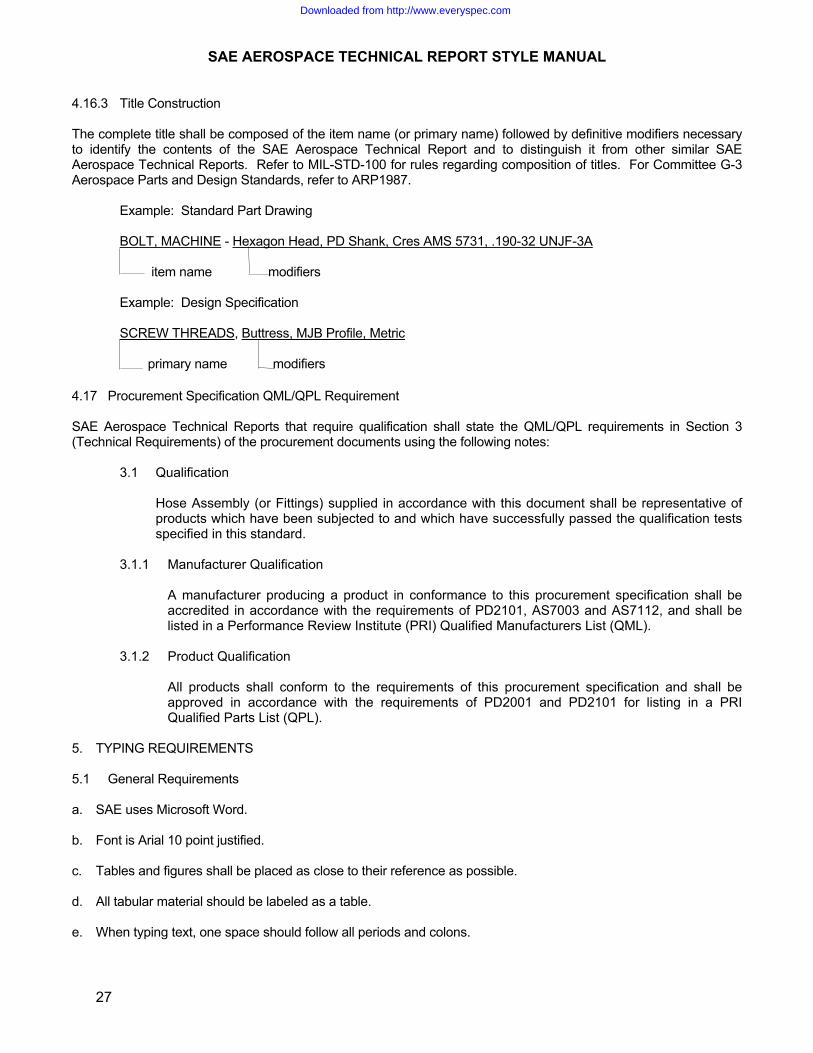
4.16.3 Title Construction The complete title shall be composed of the item name (or primary name) followed by definitive modifiers necessary to identify the contents of the SAE Aerospace Technical Report and to distinguish it from other similar SAE Aerospace Technical Reports. Refer to MIL-STD-100 for rules regarding composition of titles. For Committee G-3 Aerospace Parts and Design Standards, refer to ARP1987. Example: Standard Part Drawing BOLT, MACHINE - Hexagon Head, PD Shank, Cres AMS 5731, .190-32 UNJF-3A item name modifiers Example: Design Specification SCREW THREADS, Buttress, MJB Profile, Metric primary name modifiers
4.17 Procurement Specification QML/QPL Requirement SAE Aerospace Technical Reports that require qualification shall state the QML/QPL requirements in Section 3 (Technical Requirements) of the procurement documents using the following notes:
3.1 Qualification
Hose Assembly (or Fittings) supplied in accordance with this document shall be representative of
products which have been subjected to and which have successfully passed the qualification tests specified in this standard.
3.1.1 Manufacturer Qualification
A manufacturer producing a product in conformance to this procurement specification shall be accredited in accordance with the requirements of PD2101, AS7003 and AS7112, and shall be listed in a Performance Review Institute (PRI) Qualified Manufacturers List (QML).
3.1.2 Product Qualification All products shall conform to the requirements of this procurement specification and shall be
approved in accordance with the requirements of PD2001 and PD2101 for listing in a PRI Qualified Parts List (QPL).
5. TYPING REQUIREMENTS 5.1 General Requirements a. SAE uses Microsoft Word. b. Font is Arial 10 point justified. c. Tables and figures shall be placed as close to their reference as possible. d. All tabular material should be labeled as a table. e. When typing text, one space should follow all periods and colons.
Downloaded from http://www.everyspec.com

SAE AEROSPACE TECHNICAL REPORT STYLE MANUAL
28
6. SAE AEROSPACE PARTS OR DESIGN STANDARD FORMATS 6.1 Parts Drawing Paper - First Page 6.1.1 Parts drawing paper shall be as illustrated in Figure 2. The issue block, third angle projection, and Federal
Supply Class block shall be contained within these border lines. 6.1.2 The SAE Aerospace Parts or Design Standard number and revision letter if applicable shall be displayed in
both the lower right-hand corner and extending from the upper left corner as shown in details A and B of Figure 2. The "slash sheet" format as described in MIL-STD-961 shall not be used. For SAE Metric Aerospace "MA" Technical Reports equivalent to ISO, the number in the upper left corner shall read MAXXXX followed by ISO in parentheses [i.e., MA2002 (ISO 6772)].
6.1.3 Each sheet shall be numbered with the applicable sheet number followed by the total number of sheets as
illustrated in detail C of Figure 2. 6.1.4 The Federal Supply Class Box shall be as illustrated in detail D of Figure 2. 6.1.5 The title block shall be as illustrated in detail E of Figure 2. 6.1.6 The custodian and procurement specification information shall be placed in the block illustrated in detail F of
Figure 2. 6.1.7 Only one procurement specification shall be noted in the block. The procurement shall not be repeated in
the notes unless a virgule note has been included in front of the specification number indicating that exceptions or explanatory comments are found in the notes.
6.1.8 When a third angle projection is necessary, it shall be as illustrated in detail G of Figure 2. 6.1.9 The issue block shall be as illustrated in detail H of Figure 2. Dates shall be indicated in the following format:
1994-04 where 1994 indicates the year, 04 indicates the month as April. 6.2 Parts Drawing Paper - Second and Subsequent Pages Second and subsequent pages shall be as illustrated in Figure 3. 6.3 Editorial Requirements 6.3.1 Figures shall be numbered with an Arabic number and shall have a title as illustrated in Figure 2.
6.3.2 The use of the Ø symbol in figures and tables preceding diameters shall be used when necessary to insure
communication that a specified dimension/feature is a diameter if it is not otherwise clear from the graphic or text.
6.3.3 For typical dimensions, the phrase "2X " or "TYP" may also be used.
Downloaded from http://www.everyspec.com

SAE AEROSPACE TECHNICAL REPORT STYLE MANUAL
29
FIGURE 2 - SAMPLE FIRST PAGE
Downloaded from http://www.everyspec.com
SAE AEROSPACE TECHNICAL REPORT STYLE MANUAL
30
FIGURE 3 - SAMPLE SECOND AND SUBSEQUENT PAGES
Downloaded from http://www.everyspec.com

SAE AEROSPACE TECHNICAL REPORT STYLE MANUAL
31
6.3.4 Flag notes in figures (/#/) shall be as illustrated in Figure 2. 6.3.5 Tables shall be numbered with an Arabic number and shall have a title as illustrated in Figure 2. 6.3.6 To avoid the landscape presentation, tables may be broken up into smaller tables as illustrated in
Figure 4. 6.3.7 All text shall be presented within the Notes as illustrated in Figure 3. 6.3.8 The notes shall be presented in all caps, with the exception of lowercase abbreviations per TSB003. 6.3.9 Flag notes (/#/) within the NOTES section shall be presented as illustrated in Figure 3. 6.3.10 Zeros shall be included before the decimal when using metric values and will not be included before the
decimal in the inch-pound system. 6.3.11 To indicate changes from the previous revision, use the change bar ( I ). If the entire SAE Aerospace Parts
or Design Standard has been rewritten, the (R) symbol shall be directly to the left of the document title. When utilizing the ( I ) or (R) symbol, the following statement will be included as the last Note in the Notes Section:
The change bar ( l ) located in the left margin is for the convenience of the user in locating areas where
technical revisions, not editorial changes, have been made to the previous issue of this document. An (R) symbol to the left of the document title indicates a complete revision of the document.
6.3.12 Statement that is to be added when cadmium plating is specified/referenced:
NOTICE This document references a part which contains cadmium as a plating material. Consult local officials if you have questions concerning cadmium's use. 6.3.13 All Aerospace Parts or Design Standards must contain a Rationale. The Rationale will appear as an unnumbered paragraph at the beginning of the document before all figures or text. 6.4 Typing Requirements 6.4.1 SAE uses Microsoft Word, Aerial 8 point, all uppercase letters. 6.4.2 CAD System Preparation: Any figures/tables created using CAD must be submitted to SAE with the .dwg
extension. SAE will then convert to a usable format. 6.5 Technical Requirements 6.5.1 Presentation The primary presentation requirements consist of the following: a. Graphical representation of part(s) b. Tabular data c. Part number for each item d. Notes
Downloaded from http://www.everyspec.com

SAE AEROSPACE TECHNICAL REPORT STYLE MANUAL
32
TABLE 1 - DIMENSIONS
FIGURE 4 - EXAMPLE OF BREAKING UP LARGE TABLES
Downloaded from http://www.everyspec.com

SAE AEROSPACE TECHNICAL REPORT STYLE MANUAL
33
6.5.2 Graphical Representation Graphical representation of the part(s) shall be the first requirement presented at top of sheet 1, or the entire sheet 1, if required. The graphics shall be positioned so that the small dimension of the paper is in the vertical (portrait) position. The graphics shall define the complete configuration of the part to be manufactured, following the rules specified in MIL-STD-100 with regard to the following: a. Projection, Orientation, and Callout: Third angle projection of views per ASME Y14.3M For Committee G-3 Aerospace Parts or Design Standards, the bulkhead end of a fitting and bulkhead drawing,
shall be the left-hand end on the run except for a tee with bulkhead on side in which case, the bulkhead shall be the bottom side. Nuts, sleeves, and cap assemblies shall be shown as if the mating fitting on which they are tightened would be to the right. For Aerospace Parts or Design Standards with ports, the fitting ends on reducer fittings may be numbered such as port 1, port 2, etc. The rule of sequence is left to right and top to bottom. For fitting end callout, use the note, "FITTING END PER ________."
b. Line Conventions: Ink line conventions per ASME Y14.2M c. Typing or Lettering: Typing of notes and dimensional values is preferred; mechanical ink lettering may be used
per ASME Y14.2M for style and size d. Dimensioning and Tolerancing: Specify US Customary (inch/pound) units for dimensional values. The SI metric
soft conversions of the specified inch/pound units need not be included for information. The dimensioning and tolerancing practice (including geometric tolerance symbols) for new drawings shall be per ASME Y14.5M-1994. Existing drawings being revised shall be per the dimensioning and tolerancing practice to which they were originally prepared.
For Committee G-3, tabulated drawings will have letter codes for dimensions starting with the letter "A". The
letter "T" is generally reserved for threads. The letters shall be shown in alphabetical sequence except for threads which shall appear immediately after, NOMINAL TUBE SIZE. The first letters of the alphabet shall be used for major overall dimensions. For MA drawings, it is desirable to use the same letter codes as the ISO drawing if one exists.
e. Surface Texture Symbols: Shall be per ASME Y14.36M using microinch values for surface roughness
requirements. f. Screw Threads: Screw thread representation shall be per ANSI Y14.6. Unified screw threads and their
designation shall be in accordance with AS8879 for all aerospace applications, except electrical items and some coupling standards may specify unified threads per MIL-S-7742. The thread specification shall be listed at the top of the column heading. For metric threads, a note number referring to thread gaging per MA1566 shall be included. If all the threaded ends are called out on the drawing per fitting end standards, the T Thread may be enclosed in parenthesis on the field of the drawing and the thread specification along with the gaging note omitted. The T Thread shall include the thread tolerance.
Downloaded from http://www.everyspec.com
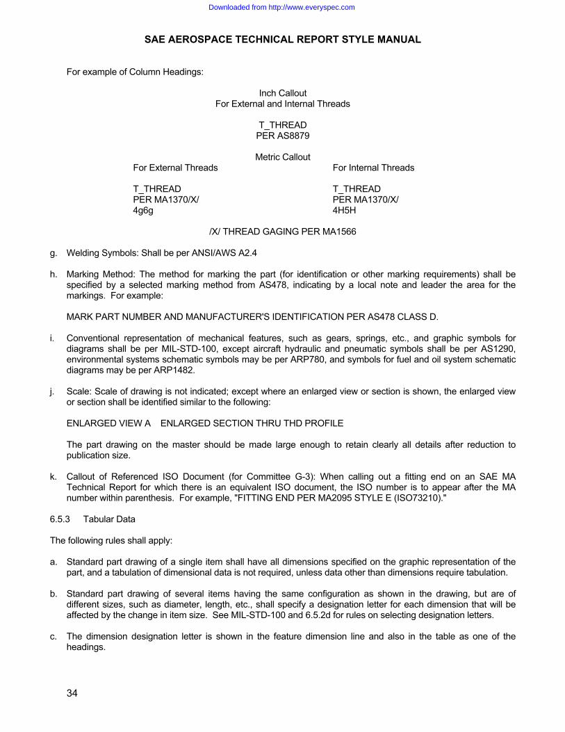
SAE AEROSPACE TECHNICAL REPORT STYLE MANUAL
34
For example of Column Headings:
Inch Callout For External and Internal Threads
T_THREAD
PER AS8879
Metric Callout For External Threads For Internal Threads T_THREAD T_THREAD PER MA1370/X/ PER MA1370/X/ 4g6g 4H5H
/X/ THREAD GAGING PER MA1566 g. Welding Symbols: Shall be per ANSI/AWS A2.4 h. Marking Method: The method for marking the part (for identification or other marking requirements) shall be
specified by a selected marking method from AS478, indicating by a local note and leader the area for the markings. For example:
MARK PART NUMBER AND MANUFACTURER'S IDENTIFICATION PER AS478 CLASS D. i. Conventional representation of mechanical features, such as gears, springs, etc., and graphic symbols for
diagrams shall be per MIL-STD-100, except aircraft hydraulic and pneumatic symbols shall be per AS1290, environmental systems schematic symbols may be per ARP780, and symbols for fuel and oil system schematic diagrams may be per ARP1482.
j. Scale: Scale of drawing is not indicated; except where an enlarged view or section is shown, the enlarged view
or section shall be identified similar to the following: ENLARGED VIEW A ENLARGED SECTION THRU THD PROFILE The part drawing on the master should be made large enough to retain clearly all details after reduction to
publication size. k. Callout of Referenced ISO Document (for Committee G-3): When calling out a fitting end on an SAE MA
Technical Report for which there is an equivalent ISO document, the ISO number is to appear after the MA number within parenthesis. For example, "FITTING END PER MA2095 STYLE E (ISO73210)."
6.5.3 Tabular Data The following rules shall apply: a. Standard part drawing of a single item shall have all dimensions specified on the graphic representation of the
part, and a tabulation of dimensional data is not required, unless data other than dimensions require tabulation. b. Standard part drawing of several items having the same configuration as shown in the drawing, but are of
different sizes, such as diameter, length, etc., shall specify a designation letter for each dimension that will be affected by the change in item size. See MIL-STD-100 and 6.5.2d for rules on selecting designation letters.
c. The dimension designation letter is shown in the feature dimension line and also in the table as one of the
headings.
Downloaded from http://www.everyspec.com

SAE AEROSPACE TECHNICAL REPORT STYLE MANUAL
35
d. Location: The table shall be placed immediately beneath the part drawing, where feasible; otherwise place on the following sheet.
e. Column Headings: Where each item size contains no other variable, such as length, the table headings shall be
similar to the following example in the order shown in Figure 5. Columns shall have a single heading. The table shall be prepared without vertical lines and without internal horizontal lines.
APPROX PART NOMINAL C MASS NUMBER SIZE A B ±.005 lb/100
NOTE: For Committee G-3 Aerospace Parts or Design Standards, refer to 6.5.3 (4) for specifying weights
FIGURE 5 - SAMPLE COLUMN HEADINGS
(1) Part Number: The complete part number shall be as shown at the top and the dash number listed below in the column. The dash numbers in the column shall all have the same number of digits equal to the largest dash size callout but shall consist of at least two digits. Add one or more zeros to smaller size dash numbers to maintain consistent number of digits as necessary. For example: the tube size shall have the letter prefix DN or the letters DN may be placed at the top of the column. The dash size shall be equal to the millimeter tube size. For example: DN12.
FOR INCH POUND DASH NUMBER
TWO DIGIT DASH SIZE CALLOUT THREE DIGIT DASH SIZE CALLOUT
ASXXXX ASXXXX 03 008 08 064 16 096 24 120
FOR METRIC DASH NUMBER
TWO DIGIT DASH SIZE CALLOUT THREE DIGIT DASH SIZE CALLOUT MAXXXX MAXXXX 05 008 14 050 40 190
(2) Nominal Size: Where applicable, the nominal size of each item is listed for identification, and is for reference only (without tolerance). Other nominal features related to the item may be used for reference, such as nominal tube size, nominal shaft size, etc.
(3) Dimensional Letter Symbol: The designation letter assigned to each feature dimension line specified on
the part drawing is also shown in the table as a column heading. If the letter symbol is a diameter dimension, then it is prefixed by the diameter symbol Ø. A tolerance shall be specified under the symbol in the column heading unless covered by the general tolerance which requires no tolerance in the heading. Where the tolerance is not the same for all values in a column, the values shall be specified as min and max on the same line, specifying the min value first and followed by a hyphen, i.e., 1.052 - 1.064.
Downloaded from http://www.everyspec.com
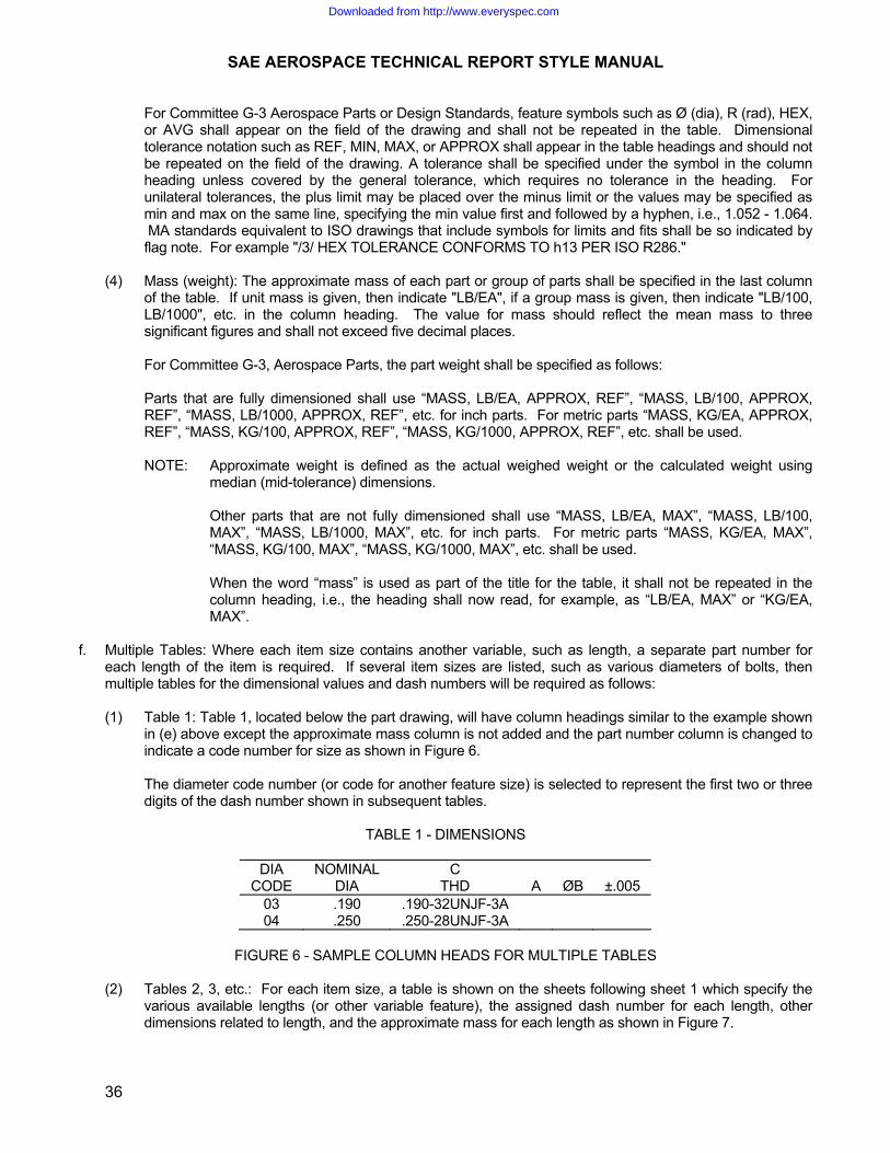
SAE AEROSPACE TECHNICAL REPORT STYLE MANUAL
36
For Committee G-3 Aerospace Parts or Design Standards, feature symbols such as Ø (dia), R (rad), HEX, or AVG shall appear on the field of the drawing and shall not be repeated in the table. Dimensional tolerance notation such as REF, MIN, MAX, or APPROX shall appear in the table headings and should not be repeated on the field of the drawing. A tolerance shall be specified under the symbol in the column heading unless covered by the general tolerance, which requires no tolerance in the heading. For unilateral tolerances, the plus limit may be placed over the minus limit or the values may be specified as min and max on the same line, specifying the min value first and followed by a hyphen, i.e., 1.052 - 1.064. MA standards equivalent to ISO drawings that include symbols for limits and fits shall be so indicated by flag note. For example "/3/ HEX TOLERANCE CONFORMS TO h13 PER ISO R286."
(4) Mass (weight): The approximate mass of each part or group of parts shall be specified in the last column
of the table. If unit mass is given, then indicate "LB/EA", if a group mass is given, then indicate "LB/100, LB/1000", etc. in the column heading. The value for mass should reflect the mean mass to three significant figures and shall not exceed five decimal places.
For Committee G-3, Aerospace Parts, the part weight shall be specified as follows: Parts that are fully dimensioned shall use “MASS, LB/EA, APPROX, REF”, “MASS, LB/100, APPROX,
REF”, “MASS, LB/1000, APPROX, REF”, etc. for inch parts. For metric parts “MASS, KG/EA, APPROX, REF”, “MASS, KG/100, APPROX, REF”, “MASS, KG/1000, APPROX, REF”, etc. shall be used.
NOTE: Approximate weight is defined as the actual weighed weight or the calculated weight using
median (mid-tolerance) dimensions. Other parts that are not fully dimensioned shall use “MASS, LB/EA, MAX”, “MASS, LB/100,
MAX”, “MASS, LB/1000, MAX”, etc. for inch parts. For metric parts “MASS, KG/EA, MAX”, “MASS, KG/100, MAX”, “MASS, KG/1000, MAX”, etc. shall be used.
When the word “mass” is used as part of the title for the table, it shall not be repeated in the
column heading, i.e., the heading shall now read, for example, as “LB/EA, MAX” or “KG/EA, MAX”.
f. Multiple Tables: Where each item size contains another variable, such as length, a separate part number for
each length of the item is required. If several item sizes are listed, such as various diameters of bolts, then multiple tables for the dimensional values and dash numbers will be required as follows:
(1) Table 1: Table 1, located below the part drawing, will have column headings similar to the example shown
in (e) above except the approximate mass column is not added and the part number column is changed to indicate a code number for size as shown in Figure 6.
The diameter code number (or code for another feature size) is selected to represent the first two or three
digits of the dash number shown in subsequent tables.
TABLE 1 - DIMENSIONS
DIA NOMINAL C CODE DIA THD A ØB ±.005
03 .190 .190-32UNJF-3A 04 .250 .250-28UNJF-3A
FIGURE 6 - SAMPLE COLUMN HEADS FOR MULTIPLE TABLES
(2) Tables 2, 3, etc.: For each item size, a table is shown on the sheets following sheet 1 which specify the
various available lengths (or other variable feature), the assigned dash number for each length, other dimensions related to length, and the approximate mass for each length as shown in Figure 7.
Downloaded from http://www.everyspec.com
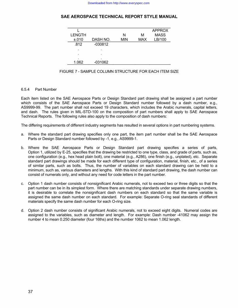
SAE AEROSPACE TECHNICAL REPORT STYLE MANUAL
37
L APPROX LENGTH N M MASS
±.010 DASH NO. MIN MAX LB/100 .812 -030812
. .
. .
. . 1.062 -031062
FIGURE 7 - SAMPLE COLUMN STRUCTURE FOR EACH ITEM SIZE
6.5.4 Part Number Each item listed on the SAE Aerospace Parts or Design Standard part drawing shall be assigned a part number which consists of the SAE Aerospace Parts or Design Standard number followed by a dash number, e.g., AS9999-99. The part number shall not exceed 19 characters, which includes the Arabic numerals, capital letters, and dash. The rules given in MIL-STD-100 on the composition of part numbers shall apply to SAE Aerospace Technical Reports. The following rules also apply to the composition of dash numbers: The differing requirements of different industry segments has resulted in several options in part numbering systems. a. Where the standard part drawing specifies only one part, the item part number shall be the SAE Aerospace
Parts or Design Standard number followed by -1, e.g., AS9999-1. b. Where the SAE Aerospace Parts or Design Standard part drawing specifies a series of parts,
Option 1, utilized by E-25, specifies that the drawing be restricted to one type, class, and grade of parts, such as, one configuration (e.g., hex head plain bolt), one material (e.g., A286), one finish (e.g., unplated), etc. Separate standard part drawings should be made for each different type of configuration, material, finish, etc., of a series of similar parts, such as bolts. Thus, the number of variables on each standard drawing can be held to a minimum, such as, various diameters and lengths. With this kind of standard part drawing, the dash number can consist of numerals only, and without any need for code letters in the part number.
c. Option 1 dash number consists of nonsignificant Arabic numerals, not to exceed two or three digits so that the
part number can be in its simplest form. Where there are matching standards under separate drawing numbers, it is desirable to correlate the nonsignificant dash numbers on each standard so that the same variable is assigned the same dash number on each standard. For example: Separate O-ring seal standards of different materials specify the same dash number for each O-ring size.
d. Option 2 dash number consists of significant Arabic numerals, not to exceed eight digits. Numeral codes are
assigned to the variables, such as diameter and length. For example: Dash number -41062 may assign the number 4 to mean 0.250 diameter (four 16ths) and the number 1062 to mean 1.062 length.
Downloaded from http://www.everyspec.com

SAE AEROSPACE TECHNICAL REPORT STYLE MANUAL
38
e. Option 3, utilized by Committee G-3, the dash number consists of one or two dash numbers of significant Arabic numerals and coded capital letters that replace the dashes or are suffixed after the second dash number. This system provides a complex part number as shown in Figure 8.
AS9999V10H1062C where, AS9999 V 10 H 1062 C FINISH CODE LETTER SECOND DASH NUMBER (LENGTH) TYPE CODE LETTER (DRILLED HEAD) FIRST DASH NUMBER (DIAMETER) MATERIAL CODE LETTER (TITANIUM 6Al-4V) DOCUMENT NUMBER
FIGURE 8 - A COMPLEX PART NUMBER Standard drawings using the Option 3 dash number are different from the preferred drawing given in (b) above
because multiple configurations, materials, finishes, etc., are specified in one drawing in lieu of separate standard drawings. This practice requires the reader of the standard drawing to compose (or decode) the complete part number, using the dash numbers and code letters that pertain to the specific part selected. For further guidelines on this dash numbering system, see ARP1590, guidelines for fluid system part numbering.
6.5.5 Notes Notes are numbered and placed under tables. See Figure 2 for examples of notes in the order that they should be specified, where applicable. For Committee G-3 Aerospace Parts or Design Standards, when the Aerospace Parts or Design Standard consists of several different components and there is no subcomponent drawing, then the material, heat treat and/or finish etc., may appear on a common table. For Metric Aerospace Parts or Design Standards having a DN column, the first note shall be, "DN = NOMINAL TUBE OUTSIDE DIAMETER". In this instance, the material note shall be note 2 and subsequent notes numbered accordingly. Other notes pertaining to the Aerospace Parts or Design Standard part drawing may follow note 6 and then notes 7 through 13 shall be renumbered accordingly in the same order as shown. The following rules shall apply to the notes: Note 1, Material: One material per standard part drawing is preferred practice. Alternative forms of the same material are permitted, e.g., AMS 5731 bar and AMS 5525 sheet. AMS specifications for materials shall be specified wherever applicable even though the AMS specification is not listed in the DODISS; suitable industry or Government specifications may be specified if no AMS specification is available for the application. Separate standard part drawings should be prepared for similar parts (such as bolts) of different kinds of materials, e.g., A286, INCO 718, Waspaloy, titanium, etc. Optional: standard part drawings may specify letter codes in the part number for different materials in lieu of separate drawings for each material. For example: "CODE T -6AL -4V TITANIUM ALLOY PER AMS 4928". Note 2, Heat Treatment: Normally, the heat treatment requirement shall be specified in the SAE Aerospace Procurement Specification, and also, in some material specifications. When exceptions to the heat treatment is required, the detailed heat treatment process (including temperature, time, quenching media, and sequence of the manufacturing operation that heat treatment shall be performed) shall be specified in Note 2. For example: "HEAT TREAT - TO CONDITION H1075 PER AMS 2759/3" or "HEAT TREAT PER PROCUREMENT SPECIFICATION".
Downloaded from http://www.everyspec.com

SAE AEROSPACE TECHNICAL REPORT STYLE MANUAL
39
Note 3, Hardness: Hardness shall be specified on the SAE Aerospace Standard Part Drawing even though it is also specified in the SAE Aerospace Procurement Specification or material specification. For Committee G-3 Aerospace Parts or Design Standards, if hardness is specified in the procurement specification or material specification it shall not be repeated on the part standard unless there is a compelling reason to do so. Hardness requirements shall show the numerical value for hardness followed by the type of hardness test using the following ISO conventions: HB, hardness Brinell HR, hardness Rockwell HV, hardness Vickers HR, hardness Rockwell Superficial HK, hardness Knoop HB denotes the usual Brinell test (10 mm ball, 3000 kgf, 10 to 15 s load application); for other conditions, the HB is supplemented by numbers indicating the test conditions in the following order: ball diameter, load in kgf, and duration of loading in seconds. For example: 63 HB/10/500/30 indicates a Brinell hardness of 63 measured with a 10 mm ball and a load of 500
kgf applied for 30 s. 277 to 363 HB indicates a Brinell hardness range of 277 to 363 measured by the usual Brinell test. In specifying Vickers hardness, the HV shall be followed by a number indicating the load and by a second suffix number indicating the duration of loading when not the normal 10 to 15 s. For example: 440 HV30 indicates a Vickers hardness of 440 measured under a 30 kg load applied for 10 to 15 s. 440 HV30/20 indicates a Vickers hardness of 440 measured under a 30 kg load applied for 20 s. In specifying Rockwell hardness, the HR shall be followed by the letter or number and letter combination denoting the scale to be used. No hyphen or space shall be used between the HR and the scale designation. For example: 26 to 32 HRC indicates a Rockwell C scale hardness range of 26 to 32. 78 to 80 HR15N indicates Rockwell Superficial 15N scale hardness range of 78 to 80. Note 4, Finish: When plating or coating is required, the standard part drawing shall specify the applicable specification for the finish process, thickness required if not covered in the specification, and whether the dimensions of the part apply before or after plating or coating even though it is stated in the specification. This plating note does not apply to Committee G-3 Aerospace Parts or Design Standards. AMS specifications should be specified wherever applicable. Note 5, Nondestructive Inspection: Heat treated parts should be subject to magnetic particle inspection per ASTM E 1444 for magnetic materials, and fluorescent penetrant inspection per ASTM E 1417 for nonmagnetic materials (other nondestructive inspection requirements, such as, X-ray and ultrasonic inspection, should be specified where required). The inspection standard for imperfections shall also be specified if not included in the procurement specification. Nondestructive inspection may or may not apply to Committee G-3 Aerospace Parts or Design Standards. Note 6, Procurement Specification: Standard part drawings should specify the applicable procurement specification that covers technical requirements not generally specified on the drawing, performance tests, quality control requirements, and packaging requirements. AS or AMS specifications should be specified wherever applicable. If no specification is applicable, enter "NONE" in this note.
Downloaded from http://www.everyspec.com

SAE AEROSPACE TECHNICAL REPORT STYLE MANUAL
40
For G-3 Aerospace Parts the procurement specification (if applicable) is specified above the title block. If a procurement specification is not applicable, add the word “NONE” above the title block. a. For Nadcap-QML, Discrete Components: /flagnote/ "PROCUREMENT SPECIFICATION: ASxxxx EXCEPT AS SPECIFIED ON THIS STANDARD.
PRODUCT SUPPLIED TO THIS SPECIFICATION SHALL BE MANUFACTURED BY AN ACCREDITED MANUFACTURER LISTED IN THE NADCAP QUALIFIED MANUFACTURER LIST (QML) FOR THIS PRODUCT TYPE. THE QML IS AVAILABLE AT www.eauditnet.com."
b. For Nadcap-QML Asssemblies: /flagnote/ "PROCUREMENT SPECIFICATION: ASxxxx EXCEPT AS SPECIFIED ON THIS STANDARD.
PRODUCT SUPPLIED TO THIS SPECIFICATION SHALL BE MANUFACTURED BY AN ACCREDITED MANUFACTURER, AND ASSEMBLED BY AN ACCREDITED MANUFACTURER OR ASSEMBLING DISTRIBUTOR LISTED IN THE NADCAP QUALIFIED MANUFACTURER LIST (QML) FOR THIS PRODUCT TYPE. THE QML IS AVAILABLE AT www.eauditnet.com."
c. For PRI-QPL, Discrete Components: /flagnote/ "PROCUREMENT SPECIFICATION: ASxxxx EXCEPT AS SPECIFIED ON THIS STANDARD.
PRODUCT SUPPLIED TO THIS SPECIFICATION SHALL BE MANUFACTURED BY AN ACCREDITED MANUFACTURER LISTED IN THE PERFORMANCE REVIEW INSTITUTE (PRI) QUALIFIED PRODUCTS LIST (QPL) PRI-QPL-ASxxxx FOR THIS STANDARD. SEE www.eauditnet.com FOR CURRENT QPL ON-LINE."
d. For PRI-QPL, Assemblies: /flagnote/ "PROCUREMENT SPECIFICATION: ASxxxx EXCEPT AS SPECIFIED ON THIS STANDARD.
PRODUCT SUPPLIED TO THIS SPECIFICATION SHALL BE MANUFACTURED AND ASSEMBLED BY AN ACCREDITED MANUFACTURER OR ASSEMBLED BY AN ACCREDITED DISTRIBUTOR LISTED IN THE PERFORMANCE REVIEW INSTITUTE (PRI) QUALIFIED PRODUCTS LIST (QPL) PRI-QPL-ASxxxx FOR THIS STANDARD. SEE www.eauditnet.com FOR CURRENT QPL ON-LINE."
e. For Items Without QPL/QML in Specification, When Control is Needed: /flagnote/ "USERS OF THIS STANDARD ARE ADVISED TO CONTROL SOURCE APPROVAL BY
STANDARD PAGE SUPPLEMENT OR SIMILAR MEANS." For G-3 Aerospace Parts or Design Standards, these notes shall be followed with "IDENTIFICATION", "WORKING PRESSURE" and interpretation of drawing note as applicable and numbered accordingly. a. "IDENTIFICATION" - The note may read "IDENTIFICATION PER PROCUREMENT SPECIFICATION" or may
give specific marking instructions. For example: "MARK PER AS478 CLASS C OR D OR METHOD 7A3, 15A3, OR 15B".
b. "WORKING PRESSURE: THIS PART IS DESIGNED FOR USE IN XXXX (specify psi for inch, kPa for metric)
WORKING PRESSURE". c. For inch pound drawings - "INTERPRETATION OF DRAWING PER ARP4296". Note 7, Surface Texture: Where specific surfaces require surface texture control, the method of designating the controls for roughness, waviness, and lay shall be per ASME Y14.36M. The technical meaning of the designation specified per ASME Y14.36M is given in ASME B46.1. The first note shown in example Note 7 shall be specified wherever surface texture control is required; whereas, the second note should be used, with applicable arithmetical average (Ra) roughness value, whenever surface roughness control is required on all remaining surfaces not designated by the roughness symbol. For Aerospace Parts or Design Standards, the note shall read, "SURFACE TEXTURE; SYMBOLS PER ASME Y14.36M; REQUIREMENTS PER ASME B46.1 UNLESS OTHERWISE SPECIFIED, MACHINED SURFACES TO BE 125 µin Ra". "MAX" is not to be used in the callout.
Downloaded from http://www.everyspec.com

SAE AEROSPACE TECHNICAL REPORT STYLE MANUAL
41
Note 8, Break Edges: "BREAK EDGES .003 TO .015 UNLESS OTHERWISE SPECIFIED". The noted example should be specified for metallic parts, except sheet metal parts (such as clamps and brackets) should specify the following note: "REMOVE BURRS AND SHARP EDGES". Die-cut nonmetallic parts, such as gaskets, should specify the note: "EDGES TO BE CLEAN CUT". Parts made from forgings or castings having fillets should specify a note similar to the following: "ALL FILLETS .005 TO .020 R UNLESS OTHERWISE SPECIFIED". Note 9, Dimensioning and Tolerancing: All Aerospace Parts or Design Standard part drawings shall follow the dimensioning and tolerancing practice in ASME Y14.5M and shall specify the following note: "DIMENSIONING AND TOLERANCING: ASME Y14.5M-1994". Note 10, Units and General Tolerances: All Aerospace Parts or Design Standard part drawings using the inch/pound system of units shall specify the following note: “DIMENSIONS ARE IN INCHES”. Where general tolerances are to be specified, should specify a note similar to the following: “DIMENSIONS ARE IN INCHES. UNLESS OTHERWISE SPECIFIED, TOLERANCES LINEAR DIMENSIONS .XX ± .YY, .XXX ± .ZZZ. ANGULAR DIMENSIONS ±X° XX’.” For G-3 Aerospace Parts or Design Standards, the general angle drawing tolerance shall be specified as 0° 30'. Note 11, Part Number Examples: This note is not required where the Aerospace Parts or Design Standard part number is given for each item in the table of dimensions. Where multiple tables are used giving the dash number for each length (or other variable) of a given item size and no code letters are assigned, the example in Note 11 should be specified to provide examples of the complete part number and the significance of the digit codes assigned in the dash number. Where letter codes are assigned for use in the part number, the meaning of each letter code and its position when applied in the dash number shall be provided. For G-3 Aerospace Parts or Design Standards, three decimal places shall be used for inch-pound units to denote the relationship of tube size to dash size. For example: "TUBE SIZE IN .062 in INCREMENTS (08=.500 in)". Note 12, Unassigned Part Numbers: The dash numbers specified in the tables of an Aerospace Parts or Design Standard part drawing are the only dash numbers that can be selected for developing the part number to be used for procurement purposes. A drawing change is required if a new size and dash number is required. All Aerospace Parts or Design Standard part drawings shall specify the note shown in example Note 12. This note is not used by Committee G-3. Note 13, Drawing Status Notes: SAE Aerospace Parts or Design Standard part drawings that are inactivated or cancelled shall specify a status note selected in accordance with the rules given in MIL-STD-962. For G-3, the drawing status shall be specified in accordance with the appropriate following note: ITEM INACTIVATION NOTATIONS. a. INACTIVE FOR DESIGN AND PROCUREMENT: When an item is made inactive and is no longer to be
procured, the note, “PART NO. XXXXX IS INACTIVE FOR DESIGN AND PROCUREMENT AS OF YR/MO/DAY. USE PART NO. XXXXX” shall be applied in accordance with instructions specified herein. Unless there is good reason to deviate, the effectivity date for inactivation shall be 3 months after the document revision date. The drawing or part standard shall also include a note per 6.5.6 of the style manual regarding instructions on the use of inactive items in inventory. Addition of the notes constitutes a change; therefore, an entry in the revision block to the next higher revision level shall be made to the part standard.
b. INACTIVE FOR NEW DESIGN, ITEM REMAINS PROCURABLE: When an item is made inactive but remains
procurable in support of old design systems, the note, “PART NO. XXXXX IS INACTIVE FOR NEW DESIGN AS OF YR/MO/DAY. USE PART NO. XXXXX FOR NEW DESIGN” shall be applied in accordance with instructions specified herein. Unless there is good reason to deviate, the effectivity date for inactivation shall be 3 months after the document revision date. Addition of the note constitutes a change; therefore, an entry in the revision block to the next higher revision level shall be made to the part standard.
Downloaded from http://www.everyspec.com

SAE AEROSPACE TECHNICAL REPORT STYLE MANUAL
42
c. INACTIVE FOR NEW DESIGN, NO REPLACEABLE ITEM: When an item is made inactive and there is no existing or new item to replace it, the note, “PART NO. XXXXX IS INACTIVE FOR NEW DESIGN AS OF YR/MO/DAY. NO REPLACEABLE ITEM” shall be applied in accordance with instructions specified herein. Unless there is good reason to deviate, the effectivity date for inactivation shall be 3 months after the document revision date. Addition of the note constitutes a change; therefore, an entry in the revision block to the next higher revision level shall be made to the part standard.
d. NOTE PLACEMENT: When a part standard is approved for inactivation, the placement of the applicable
wording shall be in accordance with d.1 and d.2 below. The notation shall not obliterate existing product information.
(1) When the entire part standard is approved for inactivation, the complete inactivation wording shall appear
immediately following the last note (usually EXAMPLE OF PART NO.) on the part standard. For multiple page documents, the word “INACTIVE” shall conspicuously appear immediately above the title block (or as near as possible) with a reference note indicator to draw attention to the complete wording per a., b., or c. appearing after the last note on the last page.
(2) When less than the entire part standard is approved for inactivation (one or more parts remain active) a
reference note indicator shall be applied next to the part(s) that are inactivated and the complete inactivation wording shown in a., b., or c. as applicable shall be applied immediately following the last note (usually EXAMPLE OF PART NO.) on the part standard. For multiple page documents, the words, “INACTIVE IN PART” shall conspicuously appear on the first page immediately above the title block (or as near as possible) with a reference note indicator to draw attention to the complete wording per a., b., or c. appearing after the last note on the last page.
6.5.6 Additional Requirements for G-3 Aerospace Parts or Design Standards Only The note "THIS IS A DESIGN STANDARD NOT TO BE USED AS A PART NUMBER" will not be used. "DESIGN STANDARD" will be added to the title. The note "INVENTORIED PARTS CONFORMING TO THE PREVIOUS LETTER CHANGE MAY BE USED TO DEPLETION" will be added to the drawing when the change does not affect functional interchangeability, reliability, or safety. The note “INVENTORIED PARTS CONFORMING TO THE PREVIOUS LETTER CHANGE MAY NOT BE USED AS OF YR/MO/DAY. THE NOTE WILL BE ADDED TO THE DRAWING WHEN THE OLD DESIGN IS DEEMED TO AFFECT RELIABILITY OR SAFETY.” Information note - For notes concerning international standardization and coordination, place flag note symbol next to the custodian and put notation in note section. For example: /9/ ASD INTEREST: FUTURE REVISIONS TO THIS STANDARD SHALL BE COORDINATED WITH ASD-STAN C4." Limiting dimensions for MJ metric screw threads are presented in MA1370. Preferred standard thread series are listed in Table 2 of AS1730. Standard thread series for Aerospace Fluid Fittings are listed in Table 3C of AS1730. The word "HEX" shall be used on the field of a drawing to designate a symmetrical figure. 7. SAE AEROSPACE SUPPLEMENT Supplement sheets may be used with documents to identify those standards that cite the specification for which the Supplement sheet is written: 7.1 Supplement Balloting 7.1.1 The Supplement will be reviewed/balloted by the parent committee only at the initial publication. 7.1.2 Subsequent Supplement sheet revisions will be considered editorial only and subject to subcommittee
ballot only.
Downloaded from http://www.everyspec.com

SAE AEROSPACE TECHNICAL REPORT STYLE MANUAL
43
7.2 Supplement Designations 7.2.1 The Supplement shall be designated in numerical sequence; i.e. AS1424SUP2 supersedes
AS1424SUP1. 7.2.2 Each revision to the Supplement shall be complete; i.e. it shall incorporate all pertinent information from
the preceding revision. There shall be only one (1) Supplement active at a time per document. 7.2.3 The Supplement must reflect the current revision of the applicable parts procurement specification and
the Supplement NUMBER shall always revert to “1” each time a new PPS revisions is referenced, i.e. AS1424ASUP1.
7.3 Instructions and Entry Format See Figure 9.
FIGURE 9 - SAMPLE SUPPLEMENT
Downloaded from http://www.everyspec.com

Downloaded from http://www.everyspec.com

Downloaded from http://www.everyspec.com

Downloaded from http://www.everyspec.com