Saarland University Faculty of Natural Sciences and...
48
Saarland University Faculty of Natural Sciences and Technology I Department of Computer Science Bachelorthesis Autonomous UAV Implementing an unmanned aerial vehicle (UAV) for surveillance tasks submitted by Philip Peter submitted June 12, 2012 Supervisor Prof.Dr. Michael Backes Advisor M.Sc. Esfandiar Mohammadi Reviewers Prof.Dr. Michael Backes Prof.Dr. Christian Hammer
Transcript of Saarland University Faculty of Natural Sciences and...

Saarland UniversityFaculty of Natural Sciences and Technology I
Department of Computer Science
Bachelorthesis
Autonomous UAV
Implementing an unmanned aerial vehicle (UAV) for surveillancetasks
submitted byPhilip Peter
submittedJune 12, 2012
SupervisorProf.Dr. Michael Backes
AdvisorM.Sc. Esfandiar Mohammadi
ReviewersProf.Dr. Michael Backes
Prof.Dr. Christian Hammer

2
�������������� ���������������� ��������������������������������� �!�"����#� �!!����� ���$%����&�� ��'�(����!��(!�!��� �&�$��)�!!��*� ��������� �������!� �����&�&�(�����+*������*� �,��)!�������$��-�� �����(�.�� /����0�������1����23����4����������(5��%�)�������������$��-����������!����!�!�%���5�%-���� ����������$���%��*!� ���5�%������� ���%����������!����������%��!���)���� ��%�������!����!�!.������ ���6������������ ������������(��� ��������$��!��� ��#� �!!�������7(�!��� ���8�'�(�������(�� ���9��!�%������� ���:�(��%����� �����)%��������*)&��%�����*� � �����$��;))���������-�� .�� <�������2��23�=2����������&�����%������(%���$��!�%�!�%)��5����!�!�7-������>�!!��&�&�� �8�����!!�(����%�����>*(����(5���$��&������� � ��%�������(���5�%)�����?%�>*����"�������@�>�������.����������"���(�A����#BBBBBBBBBBB..� � � BBBBBBBBBBBBBBBB.�������������������������������������7@��*��C�@���8� 7D����!����)��C�"�&���*��8����

4

Abstract
In recent years the use of unmanned aerial vehicles (UAV) hasincreased significantly. In this thesis we illustrate how UAVs havethe potential to become a significant privacy risk by proving that aprivate individual with a budget of 3000 Euros can build and oper-ate an autonomous UAV. We create an autonomous UAV using onlycommercially available off-the-shelf components and evaluate its per-formance for remote surveillance tasks. By documenting our platform,we provide a basis for further research into the privacy implicationsof privately used autonomous UAVs.
5

Contents
1 Introduction 91.1 Related work . . . . . . . . . . . . . . . . . . . . . . . . . . . 91.2 Contribution . . . . . . . . . . . . . . . . . . . . . . . . . . . . 101.3 Outline . . . . . . . . . . . . . . . . . . . . . . . . . . . . . . . 11
2 Hardware 132.1 UAV basis . . . . . . . . . . . . . . . . . . . . . . . . . . . . . 132.2 Sensor inputs . . . . . . . . . . . . . . . . . . . . . . . . . . . 172.3 Tracking computer . . . . . . . . . . . . . . . . . . . . . . . . 172.4 Modifications to the selected hardware . . . . . . . . . . . . . 19
3 Software 213.1 Operating system . . . . . . . . . . . . . . . . . . . . . . . . . 213.2 Basic Framework . . . . . . . . . . . . . . . . . . . . . . . . . 213.3 Our control graph . . . . . . . . . . . . . . . . . . . . . . . . . 22
3.3.1 Image processing module . . . . . . . . . . . . . . . . . 223.3.2 Spatial translation and path planning module . . . . . 263.3.3 Drone interface module . . . . . . . . . . . . . . . . . . 283.3.4 Debug nodes . . . . . . . . . . . . . . . . . . . . . . . 293.3.5 Native ROS debug nodes . . . . . . . . . . . . . . . . . 32
4 Experiments 334.1 Goals . . . . . . . . . . . . . . . . . . . . . . . . . . . . . . . . 334.2 Experimental setup . . . . . . . . . . . . . . . . . . . . . . . . 334.3 Implementation plan . . . . . . . . . . . . . . . . . . . . . . . 334.4 Results . . . . . . . . . . . . . . . . . . . . . . . . . . . . . . . 344.5 Interpretation . . . . . . . . . . . . . . . . . . . . . . . . . . . 35
5 Coda 375.1 Conclusion . . . . . . . . . . . . . . . . . . . . . . . . . . . . . 375.2 Future work . . . . . . . . . . . . . . . . . . . . . . . . . . . . 37
5.2.1 Improving the tracking algorithm and target detection 385.2.2 Improving the path planning and artificial intelligence . 385.2.3 Platform changes . . . . . . . . . . . . . . . . . . . . . 39
A Serial interface board 43
B Baseplate 45
6

C Control graph 46
D Flight logs 47D.1 08.06.2012 flight 1 . . . . . . . . . . . . . . . . . . . . . . . . . 47D.2 08.06.2012 flight 2 . . . . . . . . . . . . . . . . . . . . . . . . . 47
E Contents of the attached CD-ROM 48
7

8

1 Introduction
In recent years unmanned aerial vehicles1 (UAV) have become increasinglypopular both in military and civilian applications, such as geological sur-veys or aerial photography. The capture of a U.S. Lockheed Martin RQ-170Sentinel by Iranian military in December 2011 received widespread mediaattention [1] and a 2010 study by the U.S. Army projects an average 100%increase in required training hours for UAV operators from 2010 to 2015 [2].
These UAVs, also called drones, have the potential to become a significantprivacy risk: outfitted with a video camera, these drones can be used toobserve and record a person unnoticed and from a distance. It is even possiblefor a single person to observe multiple targets simultaneously, if these dronescan autonomously follow targets.e multiple targets simultaneously, if thesedrones can autonomously follow targets.
While there are already some drones which can be used to observe andfollow a person autonomously, these drones usually cost from 50 000 USD [3]up to 170 million USD [4] and often require an extensive support framework,typically consisting of substantial support personnel and additional groundvehicles or other support infrastructure [5]. Moreover these drones are onlyavailable to a few governments. In particular, so far such efficient surveillancecapabilities were not accessible to civilians.
The drones available to civilians are more affordable (starting at 300 USD)but also less sophisticated. If these drones are capable of any autonomousflight at all, it is usually limited to a prepared list of waypoints.
In this thesis we show that any sufficiently motivated civilian can builtan autonomous UAV capable of tracking and following a pedestrian. Thisresult suggests that we may need to adjust our privacy expectations in openareas.
1.1 Related work
Much research has been done to enable UAVs to function as reconnaissanceand surveillance vehicles including fundamental planning of flight paths (e.g.,[6, 7, 8]), tracking of a specific target (e.g., [9, 10]), searching and mappingof an area [11, 12] and even coordination of multiple UAVs to avoid blindspots [13, 14, 15]. However, most of this research assumes fixed-wing UAVs,which require a minimum air speed to stay airborne.
1Unmanned aircrafts that can either be controlled remotely or fly autonomously arecalled UAVs.
9

While the assumption of a necessary minimum speed is accurate for thelast generation of UAVs, recent technological advances have made the ideaof using multicopters as autonomous UAVs more attractive. Similar to heli-copters, multicopters have the advantage of being able to hover over a specificspot. Another advantage of multicopters is that they are able to change thedirection of their movement faster than fixed-wing aircraft of a comparablesize. This agility makes them perfectly suited for city environments and fortracking highly agile targets, such as pedestrians and cars.
Most of the research done with multicopters so far focuses on 3D-mappingof a specific environment [16], accurate positioning in a controlled environ-ment [17, 18] or coordinating multiple multicopters at the same time [19].Even though some existing multicopter solutions already provide waypointnavigation [20] and “follow-me” flight [21], these features still rely on anexternal controller to provide the GPS coordinates.
There has even been research on autonomous multicopter UAVs for track-ing of specific targets [22] and automatic landing on moving platforms [23] byKarl Engelbert Wenzel, Andreas Masselli and Andreas Zell. In these papers,the authors used a modified Wii Remote to track a specific LED patternattached to their target. The main restriction of their approach is the use ofa specific led marker and the constraint to only one such marker per scene.Their specific hardware choice also limits the reuse of their work for differenttracking scenarios. We solve these constraints by using a general purposewebcam in conjunction with a standard Linux computer. This allows us tochoose the best suited tracking algorithm for any specific scenario out of awide range of algorithms available in the field of computer vision.
1.2 Contribution
We demonstrate that it is possible for a sufficiently motivated individual tobuilt an autonomous UAV capable of tracking and following a person. Thedrone can be built using only commercially available off-the-shelf parts withina budget of 3000 Euros.
As a first contribution, we create the first autonomous UAV that can bebuilt using only commercially available off-the-shelf components and opensource software and has a completely modular design to allow replacing andenhancing individual components, such as the sensors, the path planningintelligence or the tracking algorithm. To facilitate the use of our drone asbasis for future work, we place special attention on the documentation of ourwork and provide all information necessary to replicate our results.
As a second contribution, we conduct experiments to evaluate the perfor-mance of our basic drone and judge its suitability for surveillance tasks. In
10

these experiments we focus on a basic scenario, in which a single pedestrianis tracked on an open field.
1.3 Outline
In section 2, we survey and evaluate the existing UAV solutions availableto private users, as well as possible computing hardware, sensors. We alsojustify our selection of components and describe how to interface these com-ponents with each other. In section 3, we outline the basic framework forour control software and present distinct software components, such as thetracking algorithm, the path planning module and the debugging tools. Insection 4, we describe the experimental setup, and discuss the results of theexperiments. In section 5, we conclude our work and suggest further direc-tions for future work.
11

12

2 Hardware
There is a variety of options for the drone’s hardware components. In thissection we discuss our choices and present the technical details of the selectedhardware.
The foundation for our drone is the ability to move and maneuver. Thisability is implemented by the UAV basis, described in section 2.1. In thecontext of this thesis, the drone needs to be able to interact with its en-vironment. Consequently the drone needs to be aware of its environment.The sensors used to provide the drone with the necessary information aredescribed in section 2.2. The interaction with the environment also requiresfurther processing of the sensor inputs. This processing is done by the track-ing platform, described in section 2.3. Most of the components we use to builtthe drone are common of-the-shelf components. However, connecting thesecomponents with each other needs additional effort. Section 2.4 describesthese modifications.
2.1 UAV basis
The UAV basis provides the basic maneuverability for the drone and providesthe mounting platform for the batteries, the sensors, the tracking computerand any additional hardware. In this section we describe the different hard-ware platforms that are available as an UAV basis, as well as the details ofour selected hardware.
Our hardware choice. There is a variety of possible hardware platformsavailable, in this section we will give an overview of the different options andour final selection.
The main requirements for the UAV basis are its payload capacity, itsflight time, its maneuverability and its costs. The payload capacity needsto be sufficient to carry all required sensors and the necessary processinghardware. This results in a minimum payload capacity of 500 g. The flighttime should allow for a realistic scenario, e.g. tracking a person over severalminutes in different situations and from different viewpoints. Consequentlythe vehicle should be able to stay airborne for at least 20 minutes. While thereis no concrete measure for maneuverability, a higher agility allows for fasterand more direct adjustments to changing situations. Furthermore a higheragility greatly reduces the complexity of the planning algorithms. Regardingthe cost, we set a limit of 6 000 Euros for the platform.
13
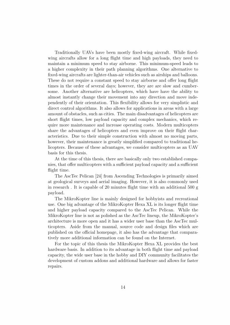
Traditionally UAVs have been mostly fixed-wing aircraft. While fixed-wing aircrafts allow for a long flight time and high payloads, they need tomaintain a minimum speed to stay airborne. This minimum-speed leads toa higher complexity in their path planning algorithms. One alternative tofixed-wing aircrafts are lighter-than-air vehicles such as airships and balloons.These do not require a constant speed to stay airborne and offer long flighttimes in the order of several days; however, they are are slow and cumber-some. Another alternative are helicopters, which have have the ability toalmost instantly change their movement into any direction and move inde-pendently of their orientation. This flexibility allows for very simplistic anddirect control algorithms. It also allows for applications in areas with a largeamount of obstacles, such as cities. The main disadvantages of helicopters areshort flight times, low payload capacity and complex mechanics, which re-quire more maintenance and increase operating costs. Modern multicoptersshare the advantages of helicopters and even improve on their flight char-acteristics. Due to their simple construction with almost no moving parts,however, their maintenance is greatly simplified compared to traditional he-licopters. Because of these advantages, we consider multicopters as an UAVbasis for this thesis.
At the time of this thesis, there are basically only two established compa-nies, that offer multicopters with a sufficient payload capacity and a sufficientflight time.
The AscTec Pelican [24] from Ascending Technologies is primarily aimedat geological surveys and aerial imaging. However, it is also commonly usedin research . It is capable of 20 minutes flight time with an additional 500 gpayload.
The MikroKopter line is mainly designed for hobbyists and recreationaluse. One big advantage of the MikroKopter Hexa XL is its longer flight timeand higher payload capacity compared to the AscTec Pelican. While theMikroKopter line is not as polished as the AscTec lineup, the MikroKopter’sarchitecture is more open and it has a wider user base than the AscTec mul-ticopters. Aside from the manual, source code and design files which arepublished on the official homepage, it also has the advantage that compara-tively more additional information can be found on the Internet.
For the topic of this thesis the MikroKopter Hexa XL provides the besthardware basis. In addition to its advantage in both flight time and payloadcapacity, the wide user base in the hobby and DIY community facilitates thedevelopment of custom addons and additional hardware and allows for fasterrepairs.
14

x
y
Figure 1: counter rotating rotors on a hexacopter
xy
z
rollpitch
yaw
Figure 2: perspective view of the multicopter showing the 3 axes and the 6degrees of control on a typical multicopter
Multicopter operating principle. The operating principle of a multi-copter varies significantly from other aircrafts. In this section we present abrief overview of the general theory of operation as well as the specific aspectsof our multicopter.
A multicopter is propelled by a number of motors with rotors directlyattached to the motor shafts. While a multicopter with any number of rotorsis theoretically possible, at least three rotors are necessary for a controlledflight. In practice most multicopters use four, six or eight rotors. In contrastto helicopters, multicopters usually have the rotor directly attached to themotor with no swashplate2 in-between. Therefore the pitch of the bladescan not be changed at flight-time. To prevent a rotation on the verticalaxis, the orientation of the rotors alternates (see figure 1). The movementof the multicopter is controlled by varying the speed of each rotor relativeto the average of all rotors. Through this, the copter can move in all threedimensions directly (see figure 2). The movement along the z-axis and theyaw rotation can be controlled individually, while the movement along thex-axis is linked to the pitch rotation and movement along the y-axis is linkedto a roll rotation.
2In a traditional helicopter a swashplate is located between the motor shaft and therotor. The swashplate allows the pilot to adjust the inclination of the rotor blades
15
While the absence of a swashplate, rudders3 and other mechanical steer-ing aids greatly simplifies the construction of a multicopter, the trade-off isan increased complexity in the control electronics. All multicopters featuresensors and microcontrollers to stabilize and balance themselves. The userdoes not control the motors directly but instead his commands are passedon to the control electronics which evaluate the copters current position andattitude and adjust the individual motor speeds accordingly.
The MikroKopter Hexa XL. On the MikroKopter Hexa XL the controlelectronics are divided into 3 distinct parts. Each of the 6 brushless MK3638motors is controlled by an individual controller, to ensure accurate powercontrol and to monitor potential hardware failures. These 6 brushless con-trollers are coordinated by the FlightCtrl board. The FlightCtrl translatesthe external absolute commands into relative commands for each of the mo-tors. It also has one 3-axis accelerometer, three single axis gyroscopes and apressure based height sensor to stabilize the multicopter. To allow an evenmore abstract control of its movement, the Hexa XL is also equipped withthe optional NaviCtrl board. This NaviCtrl uses a 3-axis magnetic compassand a GPS module to provide waypoint navigation, advanced position holdand a “Coming Home” functionality. Both the NaviCtrl and the FlightCtrlboards provide a TTL-level serial interface, which can be used to send con-trol commands to the multicopter and read out the data from the on-boardsensors.
In its standard configuration the Hexa XL can carry a 1.5 kg payload inaddition to its 2.2 kg base weight. The power supply consisting of either oneor two 6.6 Ah 4-cell lithium-ion polymer batteries which can also be used topower additional on-board hardware.
Remote control. During manual flight the Hexa XL is controlled via aFutaba T7C remote control operating on a frequency of 2.4 GHz. The remotecontrol features 7 channels, each of which can transmit one 8 bit value. 3of these channels are used to control the roll, pitch and yaw angles of thecopter. 1 channel controls the overall gas, which corresponds to the climbrate during normal flight. The 5th channel is used to activate the dynamicheight hold capabilities of the Hexa XL during flight. The height hold featureallows for a more accurate control of the copter during flight, but it has tobe disabled during takeoff and landing. The 6th channel is used to selectbetween the manual flight, the position hold and the coming home modes of
3On an aircraft the rudder is usually located on the tailfin of the craft. It is used tocontrol the yaw of the craft.
16

the Hexa XL. Similar to the dynamic height hold, the position hold providesa better control over the copter during the flight, but should be disabledduring takeoff and landing. The coming home mode is used to transfercontrol over to the tracking computer. The 7th channel of the remote controlenables the CareFree mode on the Hexa XL. During CareFree operation, theremote control commands are interpreted in reference to the copter’s originalorientation instead of its current heading. This allows the copter’s operatorto safely control the Hexa XL, even if the operator can’t determine wherethe front of the copter is. CareFree has to be activated to allow the copterto automatically turn towards the tracking target.
2.2 Sensor inputs
The sensor inputs are necessary in order to establish the position of thedrone as well as the position of the tracking target. While a purely relativetracking is possible, knowing the absolute coordinates of the drone and itstarget, allows us to establish safe boundaries for the drone and limit itsactions to stay within these boundaries. However, the MikroKopter HexaXL system already provides the accelerometer, gyroscope, GPS, compassand height sensor to determine the drones position and movements. Sincethese sensors are accurate enough and can be read by the tracking computer,only an additional tracking sensor is needed.
As the tracking feature was defined as an optical marker, an optical sys-tem is necessary to track this marker. This system should have a sufficientlyhigh resolution to recognize the tracking target even from a height of approx-imately 20 m and should update fast enough to follow a moving person.
Even though it is possible to connect an analog video source to a com-puter, an analog connection is only useful for specialized cameras such asthermal imaging or ultra low light cameras. For the environment of thisthesis, however, even simple USB webcams provide enough resolution and asufficiently high frame rate to fulfill the requirements. For this thesis a Mi-crosoft cinema HD webcam was chosen, mainly for its easy mounting option.
2.3 Tracking computer
The tracking computer runs the detection and tracking algorithms as well asany additional software needed to send the control commands to the droneson-board NaviCtrl board. The main consideration for the tracking computeris the balance between power and size. On one hand the tracking computerneeds to be powerful enough to process a live video feed, on the other handit should be light enough to fit on to the drone and not exceed its payload
17

capacity. For our tracking computer the minimum requirements were set toa processor speed of at least 700 MHz and a minimum of 512 MB RAM. Themaximum weight, space and power requirements were given by the drones1.5 kg payload limit and the 13.7 V 6.6 Ah battery pack.
Hardware architectures. While many different computer architecturesexist, there are two main categories, that are commonly used. ARM-basedembedded systems and x86-based, small-form-factor computers. Using atracking computer from one of these two categories, allows us to to use avast amount of material and information already available on the Internet,thus accelerating the development process.
The ARM-based embedded systems are far smaller and more power ef-ficient than their x86 counterparts. The gumstix Overo Fire COM with a720 MHz ARM Cortex-A8 CPU and 512 MB RAM only weighs 5.6 g anduses less than 2 Watts of power. While other ARM-based systems might bebigger, their size is mostly dictated by the space needed for their extensionconnectors. However, the main drawback of all ARM-based systems is theirpoor support for most third party software. While many Linux distributionshave begun to provide ARM ports of their base system, many libraries andprograms have not yet been ported to this architecture. And since the userbase is still a lot smaller than for x86-based systems, community support isalso limited.
Most small-form-factor x86-based systems are built with processors fromIntel’s Atom CPU family. However, there are also systems based on other In-tel, AMD and Via processors available. This offers more potential to upgradethe computing platform in the future, without the need to adapt the soft-ware. Currently the most powerful ARM-based platform is the PandaBoard[25] with a dual-core 1.2 GHz ARM-Cortex A9 CPU and 1 GB RAM. In con-trast several x86 mainboards with a 3.1 GHz Intel dual-core CPU and 16 GBRAM are available [26]. While x86-based systems provide a wider range ofoptions, the smaller and lighter systems are normally niche products withcorrespondingly higher prices, therefore the main choice is between price andsize, while the processing power of the systems does not vary as much.
Selected hardware. Even though two ARM-based systems were evaluatedat first, a x86-based fit-PC2i [27] was selected as the tracking computer. Thefit-PC2i contains a 1.6 GHz Z530 Intel Atom CPU and 1 GB RAM. The fit-PC2i can be used as a normal desktop computer, which facilitates debuggingand testing. The fit-PC2i also accepts a wide range of input voltages from8 V - 15 V at 600 mA. While the weight of 370 grams is heavier than a
18

comparable ARM-based system, the weight is acceptable in the context ofthis thesis.
2.4 Modifications to the selected hardware
Since many of the individual hardware components are not specifically builtas UAV components, some additional modifications are necessary to connectthe components to each other. While these modifications were mostly minormechanical and electrical changes, all are detailed in this section.
The connection between the tracking computer and the NaviCtrl boardis done with a custom USB to serial converter based on an ATMega32U4microcontroller. This serial converter also provides a 2.4 GHz radio link, overwhich the communication between the NaviCtrl and the tracking computercan be monitored from a base station. Additionally the serial converter boardcan also receive commands via this radio link and either insert them into theserial data stream or emulate a USB keyboard in case user input is need onthe tracking computer. As a debugging aid the serial converter board willalso indicate with an LED when the tracking computer is fully booted.
Since the fit-PC2i requires an input voltage between 8 V and 15 V, butthe maximum voltage of a fully charged battery pack can be 16.8 V, three1N4001 general purpose rectifier diodes have been inserted into the powerlead to the tracking computer. Each of these diodes has a forward voltagedrop between 0.6 V at 10 mA and 1.4 V at 20 A depending on the forwardcurrent [28]. Therefore the three diodes produce and overall drop of 1.8 Vto 4.2 V. Since the forward current is approximately 0.7 A during normaloperations, the most likely voltage drop will be approximately 3 V. Thisreduces the batteries maximum voltage of 16.8 V to approximately 13.8 V.The minimum safe voltage of the battery of 12 V is reduced to 9 V, which isstill in the fit-PC2i’s accepted input range.
To house the additional hardware an aluminum baseplate was added be-low the battery compartment. This plate provides mounting holes for thetracking computer, the serial converter board and the webcam.
19

20

3 Software
The software system installed on the tracking computer is responsible foridentifying the target and issuing the correct commands to the drone’s Nav-iCtrl, so that the drone will follow the target. This software system consistsof the operating system (section 3.1), a robotics framework (section 3.2) andthe control software (section 3.3). In this section the components of thissoftware system are described.
3.1 Operating system
As the operating system for the tracking computer the Linux distributionUbuntu was chosen. Ubuntu is supported by all libraries and programs usedfor this thesis and it is the recommended operating system for the ROSframework. Due to its popularity much additional documentation is avail-able. Another advantage of Ubuntu is its support for ARM based computers,for future changes int the tracking hardware.
3.2 Basic Framework
One main goal for the drones software system is modularity to allow easyexpansion and modification. In particular exchanging or adding trackingalgorithms and sensor inputs should be possible without a complete redesignof the rest of the systems. To facilitate the design process the ROS framework[29] was used. While there are many different robotic frameworks such asMicrosoft Robotics Developer Studio [30], Urbi [31] and YARP [32] available,ROS offers some key advantages over these alternatives. Particularly, theavailability of various diagnostic and documentation utilities make ROS avery suitable choice. Moreover building our system on top of ROS allowsus to reuse our system on a variety of hardware platforms, since ROS iscompatible with a wide range of computer architectures.
A software system built on top of ROS can be described as a controlgraph in which the nodes represent individual processes and the edges, called“topics” in ROS, specify the communication channels between these nodes.Nodes can be implemented in a variety of programming languages. The twoofficially supported languages are C and Python, but implementations forother languages such as Java and Matlab are also available. Multiple nodescan publish as well as subscribe to the same topic. Since the topics areimplemented via TCP and UDP connections, a control graph can scale overmultiple machines without any additional configuration. Nodes can also beadded and removed during runtime. This flexibility is of special importance,
21
multicopterinterface
copterinterpreter
serialbridge
multicopter data and control interface
trackingalgorithmcamera
tracking and image processing
GPStransform
targetselection
pathplanning
safetycheck
spatial translation and planning
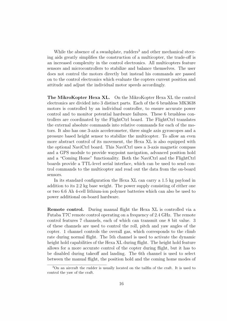
Figure 3: a simplified representation of the control graph. A representationshowing all debug nodes used during flight can be found in appendix C figure 13
since it allows us to easily move nodes from the drones on-board computersystem to a ground station for debugging purposes.
3.3 Our control graph
The control graph tries to estimate the target’s location based on the sensorinput received from the drone and the target’s previous location. Accordingto these inputs it then maneuvers the drone into an optimal vantage pointto surveil the target. The control graph itself can be divided into threedistinct modules, each of which contains multiple ROS nodes (see figure 3).These three parts are the image processing module (section 3.3.1), the spatialtranslation and planning module (section 3.3.2) and the interface module(section 3.3.3). In addition to these modules some debug nodes were used(section 3.3.4 and section 3.3.5).
3.3.1 Image processing module
The image processing module is responsible for the identification of the targetwithin the acquired images. This module includes both the hardware inter-face with the drones camera, as well as the subsequent algorithm to isolate
22

1. convert to HSV
2. apply a threshold to the binary image
3. perform morphological opening
4. compute bounding circles
Table 1: detection algorithm
the tracking target.
Camera. For the USB camera interface the “usb cam” node from the BoschResearch and Technology Center was used [33]. This driver proved to be veryversatile and stable. The camera node is run with a resolution of 352 ∗ 288pixels at 15 frames per second.
Tracking algorithm. For the purpose of this thesis a simple “tracking bydetection” algorithm is used. A general overview of this algorithm is givenin table 1 and example of the individual steps can be seen in table 2. TheOpenCV framework [34] was used to implement the individual processingsteps.
Since the target is identified through its distinct color, the camera imageis first transformed into the HSV color space. In contrast to the RGB colorspace HSV describes colors through their hue, saturation and value. Thehue of a given color is expressed as an angle between 0◦and 360◦. A hueof 0◦corresponds to red, while 120◦and 240◦represent green and blue respec-tively. The saturation ranges from 0 to 1, with 0 representing a neutral greyand 1 being a completely saturated color. The value ranges from 0 to 1 aswell and can be considered as the brightness of the color, 0 being black and1 being white. In HSV color space the various shades of grey ranging fromblack to white can not be assigned a clear hue, since any hue combined with asaturation of 0 will result in the same color. Similarly the hue and saturationfor black and white are irrelevant since these colors are only defined by theirvalue.
The advantage of the HSV color space over other representations is thatthe hue and saturation of a given object are mostly consistent under changinglighting conditions, since only the value corresponds to the brightness of thecolor. In our algorithm the target is therefore primarily identified throughits hue. Value and saturation are only used as a minimum requirement to
23

ensure no false positives through black, grey and white areas.After the conversion to the HSV color space we create a binary image
in which all areas that were our target’s hue in the original camera imageare completely white (255) and everything else is black (0). This is doneaccording to the following formula:
pixel(x, y) =
{255 if hmin ≤ h(x, y) ≥ hmax, smin ≤ s(x, y), vmin ≤ v(x, y)0 else
After this thresholding operation we remove potential noise in the the binaryimage with a morphological opening (see also [35]). A morphological openingconsists of a erosion followed by a dilation. The purpose of the opening isto remove isolated white pixels, while preserving the shape and size of largerwhite areas.
During the erosion all white pixels, which are not completely surroundedby white pixels are replaced with black pixels. Therefore all white areassmaller than 3 ∗ 3 pixels are eliminated. The following dilation replaces allblack pixels that border at least one white pixel with a white pixel themselves.This restores all remaining white areas to their general shape and size.
As a final step bounding circles are computed for every area of whitepixels. For each area the smallest circle is calculated that would fully enclosethe white area. The coordinates can then be used as a rough estimationof the areas center, while the radius of the circle can be used to estimatethe areas size. The center and radius of these circles are then published asdetection results.
24

The input image
The individualhue, saturation
and valueimages
The binaryimage afterthresholding
The binaryimage after themorphological
opening
Table 2: The different stages of the tracking algorithm
25

multicopterinterface
copterinterpreter
serialbridge
multicopter data and control interface
detectionalgorithm
camera
tracking and image processing
detectionalgorithm
trackingalgorithm
camera
detectionalgorithm
targetselection
pathplanning
safetycheck
GPStransform
spatial translation and planning
GPStransform
Figure 4: possible extension of the control graph
3.3.2 Spatial translation and path planning module
The spatial translation and path planning module selects the final target andcomputes the necessary actions to keep this target centered in the cameraview. It also contains safety checks to ensure that the multicopter stayswithin its allowed operational area. The path planning section uses GPScoordinates as the main representation for 3D positions. This simplifies in-terfacing with external components and reduces the likelihood of programmererrors compared to an arbitrary coordinate system.
The main steps for the spatial translation and path planning are thetransformation from pixel coordinates to GPS coordinates, the target selec-tion, the determination of the best vantage point to surveil the target and asafety check, to ensure the drone stays within its allowed area of operation.
While it might seem unintuitive to first transform the relative pixel co-ordinates into GPS coordinates and then select the most likely target, thisprocessing order enables us to aggregate tracking information from multiple
26

groundtarget
distance
Figure 5: The GPS transformation estimates the distance of the target basedon the drones height and the angle α which can be calculated from the relativeposition of the target inside the video frame. A level ground is assumed to simplifythe calculation
cameras with different orientations and optical characteristics (see figure 4).
GPS transformation. The GPS transformation node translates the pixellocations of each detected target into GPS coordinates, based on the dronesheight and heading, the view angle of the specific camera and the locationof the target inside the camera picture. This is done by first calculating thelocation of the detected target relative to the drone (see figure 5), afterwardsthe relative position of the target is transformed into GPS coordinates basedon the drones coordinates using the haversine formula [36]. Even though thehaversine formula can introduce an error, due to its approximation of theearth as a perfect sphere, his imprecision is negligible compared to the ac-curacy of the drones GPS unit. The haversine formula was used to simplifythe development process. If a more accurate calculation should become nec-essary, the GPS transformation node can easily be exchanged with a versionbased on Vincenty’s formula. The current algorithm also does not compen-sate for any roll of the drone, currently the GPS transformation only outputscoordinates if the roll factor is below 5◦.
Target selection. The target selection node reduces a list of possible tar-get coordinates to the one set of coordinates that most likely corresponds tothe actual target. The node receives a list of GPS coordinates for potentialtargets along with a confidence value for each target. In the current imple-
27

target
nextwaypoint
current position
posiblewaypoints
Figure 6: path planning
mentation this confidence value is solely based on the size of the detectedarea. The node then selects the most likely target based on the confidencevalues and the distance of each target from the last known target location.The most likely target is then forwarded to the path planning node.
Path planning. The path planning node calculates the optimal positionat which the target’s GPS location should be centered in the main cameraview. Based on the copters height a radius around the target’s GPS locationis calculated from which the target should be visible. The next position isthen selected by calculating the closest intersection between this circle andthe line defined by the drone’s current position and the target position (seefigure 6).
Safety check. Before any movement commands are sent to the dronescontrol interface, the safety check node calculates the distance between thenew position and the drone’s starting position. Only when the new position iswithin a predefined range of the starting position, the command is forwardedto the control interface.
3.3.3 Drone interface module
The interface section translates between the drone’s lower level controls suchas the NaviCtrl and FlightCtrl boards and the higher level computer running
28

the tracking and planning algorithms. This section describes the individualnodes necessary to pass sensor data and waypoint information along betweenthe drone’s flight control and the control graph.
Serial bridge. The serial bridge provides an interface between the controlgraph and the USB serial interface board. This node is a slightly modifiedversion of the node provided by ROS [37]. We added support for a 57600baud rate and pass through of carriage return characters (ASCII code 0x0D)in the serial input.
Copter interpreter. The copter interpreter decodes and encodes the drone’snative serial protocol and calculates and checks the necessary checksums.This node is also responsible for requesting data about current position inregular intervals and transmitting new waypoint information back to thedrone.
3.3.4 Debug nodes
In addition to the previously mentioned nodes, several nodes have been cre-ated to facilitate the development of the control graph. These nodes can berun on a ground station while the drone is in flight to monitor its status.They can also be used evaluate recorded data from previous experiments.
Copter visualization. The main purpose of this node is to ensure thecorrect operation of the drone during experiments. This node provides in-formation about the drones status, such as the current altitude, the GPSquality, the battery power and other general data (see figure 7).
It also shows the five different GPS points relevant to the nodes operation:The drones current position, the home position from which the drone started,the target’s position and two different waypoint positions. The current way-point is read out from the NaviCtrl board and indicates where the drone iscurrently heading. The projected waypoint is the last waypoint calculatedbased on the target’s position. During normal operation these waypointsshould be identical. However, the current waypoint might lag a bit behindthe projected waypoint, due to the communication overhead between thetracking computer and the NaviCtrl board. If the the two waypoints differwildly for a prolonged time, it indicates either that a problem with commu-nication between the tracking computer and the NaviCtrl board exists, orthat the drone is configured incorrectly for autonomous flight.
In addition to the textual data, the node also shows a video image fromthe drone’s camera with an overlay of the current target. There are two
29

Figure 7: The copter visualization node. The red circle denotes the targetsposition based on its relative image coordinates, while the blue circle denotes thetargets position based on its calculated GPS coordinates. The color of the textindicates the relative freshness of the data, fading from green to red over the courseof 10 seconds.
30

home position
current position
target position
next waypoint basedon current target po-sition
current waypointread out from dronesnavigation data
maximum allowedmovement range
near (inner circle)and far (outer circle)field-of-view for thecamera
Table 3: The map visualization node
indicators for the current target. A red circle shows the target based onthe relative image coordinates, while a blue circle shows the position of thetarget based on the calculated GPS coordinates. A purple circle indicatesthe drone’s home position.
Map visualization. The map visualization node is mostly used to validatethe accuracy of the path planning algorithm before transferring the controlto the drone. This node displays the current position of the drone, its homeposition and the target’s position on a 2D top-down map (see also table3). The two different waypoints are also displayed. This allows the drone’soperator to verify that the drone actually accepts the calculated waypoints.Next to each position its distance to the drone’s current position is indicated,for the drone itself, the distance between the drone and the home position isshown. Additionally the visualization shows the maximal range of the droneas a red circle and the viewing area of the camera as green circle. The viewingarea is computed based on the camera angle and the current altitude of thedrone. The maximum viewing distance of the camera is also displayed inthe bottom left corner, as this can often exceed the size of the visualizationwindow.
31

Tracker visualization. The tracker visualization node aids during thefine-tuning of the tracking algorithm. This node displays the RGB videoas well as the individual hue, saturation and value images from the maincamera. It also overlays all currently detected targets on top of the videofeed. To help the operator in finding the correct parameters, it additionallydisplays the HSV values of the center pixel of the video feed.
3.3.5 Native ROS debug nodes
ROS also provides some nodes to aid during the development process. The“rxgraph” and “rosbag” nodes were especially useful. Rxgraph allows theuser to view the current layout of the control graph. This can show miscon-figured topics and missing nodes. Rosbag records specified topics for laterplayback in bag files. These bag files allow the fine tuning of the trackingalgorithm under controlled conditions as well as dry-runs of the completecontrol graph with realistic inputs.
32

4 Experiments
In order to evaluate the practical performance of the drone’s hardware andsoftware, we performed some experiments. The goals (section 4.1), the setup(section 4.2), the execution (section 4.3), the results (section 4.4) and theevaluation (section 4.5) of these experiments is described in this section.
4.1 Goals
The goal of the thesis is to build a drone, which is able to follow a personwearing an easily distinguished marker. The experiments focused on twomain factors: The drone should be able to orient itself, so that the targetremains visible and if necessary the drone should be able to follow the targetwhile it is moving. Obstacles and occlusions were not included during theseexperiments
4.2 Experimental setup
This section describes the basic environment of the experiments. The exper-iments took place on an open field and during the day with minimal cloudcoverage and minimal wind. The target was a person walking on the groundat varying speeds and in varying directions. This person was wearing a brightorange safety vest as a tracking marker.
For safety reasons, the drone was only allowed to move up to 30 metersin any direction from it’s starting point. Additionally the drone’s minimumaltitude was set at 8 meters and its maximum flight height was limited to 40meters. The drone was not allowed to exceed a ground speed of 50 km/h.
4.3 Implementation plan
The actual execution of the experiment consisted of a few consecutive actions,which are detailed in this section (see also table 4).
First the drone was manually started and steered to a height of approxi-mately 10 m by a human pilot. The drone was then oriented in a way thatthe target was visible and recognized by the tracking algorithm. After atarget lock had been confirmed by the drone’s operator via a computer onthe ground, the control was transfered to the tracking computer on-boardthe drone, while the human pilot stood by for safety reasons. At any timeduring the experiment, the control could be transfered back to the humanpilot via switch on the radio control. After the control was transfered to thedrone, the tracking target started to move while the drone’s actions were
33

1. manual takeoff
2. orient the drone, such that the target is visible
3. transfer control to drone
4. perform experimentsthe target walks in a circle around the dronethe target walks away from the dronethe target walks towards the dronethe target walks in a random pattern
5. resume manual over the drone
6. manual landing
Table 4: Implementation plan
monitored by the human pilot and by the drone’s operator via the groundstation. To confirm that the drone is able to move autonomously, the track-ing target would first walk sideways around the drone at a constant distance,to verify, that the drone would change its orientation to keep the target insight. Then the target would move away from the drone and wait for it tofollow. Afterwards the target would move towards the drone, to move thedrone back to its original position. After these preliminary tests, the targetwould start to walk in a random pattern.
4.4 Results
In the video feed recorded by the drone a wave like distortion is sometimesvisible (see figure 8).4 However, the drone was able to follow the the targetconsistently at a height of 8 m to 12 m. At higher elevations the targetwas not recognized reliably enough to allow a useful tracking. During theexperiments the drone seemed to react quicker to a target moving away fromit, then to a target moving towards it. The drone also seemed to loose thetarget during faster movements.
4This effect can be better observed in the videos, which can be found in the supportingmaterials.
34

Figure 8: some distortion can be observed on the legs of the right person
4.5 Interpretation
While the tracking functionality is still very basic, the experiments haveshown, that the drone can be used as a basis for further work.
The video distortion is most likely from the vibrations of the drone’smotors. While the distortion doesn’t seem to degrade the drone’s trackingability, a more sophisticated mounting system would decouple the camerafrom the Hexa XL’s frame and minimize the vibration of the motors.
The limited tracking height is most likely a result of using a simple USBwebcam as input device. Replacing the camera with a model with a smallerfield-of-view should allow the drone to maintain a target lock from higheraltitudes.
The slow reaction to a target moving towards the drone, is probably aresult of the simplistic path planning algorithm. If the target is further awayfrom the drone, the targets movement will have less effects on it’s relativeposition in the video frame, than similar movements will have for a closertarget (see also figure 5). A path planning algorithm, that takes the stretchedview of the video feed into account should react similar to both movementstowards and away from the drone.
The target loss during movement could be addressed by using a cam-era mounting bracket which automatically compensates for roll and pitchchanges during movement. These mounting options are available as commonaccessories for the MikroKopter.
35

36

5 Coda
This sections gives a summary of the results of this thesis and suggest furtherdirections for future work.
5.1 Conclusion
The drone described in this thesis is capable of tracking a marked target au-tonomously. It is built using only commercially available off-the-shelf compo-nents with a total cost of approximately 3000 EUR (see table 5). While thedrone in its current state is not yet a serious privacy threat, it demonstratesthat the potential for more serious privacy implications exist. Replacing thetracking algorithm with a more sophisticated variant would vastly improvethe drones viability as a surveillance tool. As computer processors continueto become more efficient and remote controlled multicopters become morecommon among hobby users, privacy concerns will become an importantissues in the future.
5.2 Future work
As one of the goals of this thesis is the development of a hardware plat-form to further research the implications of autonomous UAVs on privacyissues, the drone provides an excellent basis for further research and devel-opment. In this section we show some of the possible future improvements.These improvements fall into three categories: tracking and target detection(section 5.2.1), path planning and artificial intelligence (section 5.2.2) andgeneral platform changes (section 5.2.3).
MK Basicset Hexa2 1 300 EURNaviCtrl board and GPS board 300 EURBatteries and charger 450 EURRemote control sender and receiver 350 EURAdditional screws and mounting material 50 EURMicrosoft cinema HD webcam 50 EURfit-PC2i 350 EURAdditional electronic components 100 EURtotal costs 2 950 EUR
Table 5: Approximate costs of the final drone
37
5.2.1 Improving the tracking algorithm and target detection
There is a variety of ways to improve the drone’s tracking algorithm, bothby improving the software as well as with hardware changes.
The necessity of an external tracking marker on the target can be removedby replacing the tracking algorithm with a more advanced variant, such asthe TLD algorithm [38]. Using a more advanced algorithm would allow thedrone to track arbitrary targets without the need for a cooperative target.
As previously described, changing the camera to a model with a smallerfield-of-view would allow the drone to observe the target from a higher al-titude and greater distance. The disadvantage of a smaller field-of-view isthe increased time needed to search an area, after the target has been lost.However, utilizing two cameras with different fields-of-view or a single cam-era with a zoom-lens would allow the drone to get high-detail target images,while still enabling it to get a wide angle overview of its area-of-operationwhen needed.
In its current state the drone will only be able to reacquire a movingtarget, if it is still in the drone’s field of view. However, adding a movementestimation would allow the drone to search for the target at the target’s esti-mated position instead of the last position at which the target was seen. Suchan estimation algorithm would be especially useful for fast-moving targetswith a regular moving pattern such as cars.
To improve the position estimation of the target on uneven terrain, astereo camera or distance sensor could be used. Knowing the exact distanceof the target would greatly improve the precision of the calculated position,compared to estimating it based on the drone’s altitude.
For the operation in an urban environment the drone could utilize mapdata to recognize obstacles between the itself and the target and calculatefrom which vantage point the best visibility of the target can be achieved.Combined with movement estimation, this could also be used to predictwhere a target is going to reappear after crossing under a bridge or througha tunnel.
5.2.2 Improving the path planning and artificial intelligence
Since the drone has so far only performed in open areas, the path planningis still very rudimentary. Therefore there are many opportunities for furtherimprovement.
To allow the drone to perform in a wider range of environments someobstacle detection is elementary. The most basic variant would be to usea map to allow the drone to avoid bigger objects, such as buildings and
38

mountains. However, to avoid trees, road signs and other smaller objects,some kind of 3D environment mapping is necessary. Adding a laser scannerto the drone’s sensors would allow such mapping to be performed.
If a 3D map of the environment is available, the drone could also use dif-ferent environmental features to its advantage, such as hiding behind treesto avoid detection or perching on top of structures to conserve power. Thiswould require not only the 3D data, but also a sophisticated artificial intel-ligence.
To surveil a target for a longer duration, multiple cooperating dronescould be used. These drones would need to be able to share not only thecurrent target’s position, but also any kind of additional data, such as a 3Dmap of the environment or additional tracking features of the target, whichare currently not visible. Furthermore, a swarm of drones could also be usedto track a target from different angles or to search for a target more efficiently.
5.2.3 Platform changes
Many of the previously mentioned improvement would require an increase inprocessing power as well. Changing the tracking computer to a more efficientmodel could result in more intelligent drones of the same size, or smaller, lessvisible drone with similar capabilities as the current drone.
While multicopters are very versatile for most tracking scenarios, thesoftware system and sensor platform could also be extended to other aircraftsystems. Multicopters are very useful for short surveillance tasks and surveil-lance in areas with many obstacles, such as urban environments. However,for the surveillance of fast moving targets and for operations requiring longerflight times, fixed wing aircrafts are better suited.
To perform even longer surveillance tasks airships could be used. Sinceairships provide a very long flight-time but only have limited maneuverability,a hybrid approach could be tried. One application could be a search-and-rescue mission, in which an airship would provide a general overview of thesearch area while smaller multicopter or fixed wing aircraft would be send toconduct a more detailed search of specific locations.
39

References
[1] S. Peterson and P. Faramarzi, “Iran hijacked us drone, says iranian engi-neer,” The Christian Science monitor, 2011 (accessed June 5, 2012). [On-line]. Available: http://www.csmonitor.com/World/Middle-East/2011/1215/Exclusive-Iran-hijacked-US-drone-says-Iranian-engineer-Video
[2] M. E. Dempsey, “Eyes of the army - u.s. army roadmapfor unmanned aircraft systems 2010-2035,” 2010. [Online]. Avail-able: http://www-rucker.army.mil/usaace/uas/US%20Army%20UAS%20RoadMap%202010%202035.pdf
[3] U.S. Airforce, “WASP III factsheet,” 2011 (accessed June 5,2012). [Online]. Available: http://www.af.mil/information/factsheets/factsheet.asp?id=10469
[4] ——, “FY 2011 Budget Estimates,” 2010. [Online]. Available: http://www.saffm.hq.af.mil/shared/media/document/AFD-100128-072.pdf
[5] army-technology.com. (2012 (accessed June 5, 2012)) Shadow 200 RQ-7Tactical Unmanned Aircraft System, United States of America. [Online].Available: http://www.army-technology.com/projects/shadow200uav/
[6] T. G. McGee, S. Spry, and J. K. Hedrick, “Optimal path planning in aconstant wind with a bounded turning rate,” 2005.
[7] J. Lee, R. Huang, A. Vaughn, X. Xiao, J. K. Hedrick, M. Zennaro, andR. Sengupta, “Strategies of path-planning for a uav to track a groundvehicle,” 2003.
[8] J. C. Rubio, J. Vagners, and R. Rysdykz, “Adaptive path planning forautonomous uav oceanic search missions,” 2004.
[9] I. Shames, B. Fidan, and B. D. O. Anderson, “Close target reconnais-sance using autonomous uav formations,” 2008.
[10] F. Ra, S. Khan, K. Shaiq, and M. Shah, “Autonomous target followingby unmanned aerial vehicles,” 2006.
[11] J. Tisdale, Z. Kim, and J. K. Hedrick, “Autonomous path planning andestimation using uavs,” 2009.
[12] H. Bendea, P. Boccardo, S. Dequal, F. Giulio Tonolo, D. Marenchino,and M. Piras, “Low cost uav for post-disaster assessment,” 2008.
40
[13] J. Kim and Y. Kim, “Moving ground target tracking in dense obstacleareas using uavs,” 2008.
[14] E. Semsch, M. Jakob, D. Pavlicek, and M. Pechoucek, “Occlusion-awaremulti-uav surveillance of multiple urban areas,” 2010.
[15] E. Semsch, M. Jakob, D. Pavlicek, M. Pechoucek, and D. Sislak, “Au-tonomous uav surveillance in complex urban environments,” 2009.
[16] A. Bachrach, R. He, and N. Roy, “Autonomous flight in unknown indoorenvironments,” International Journal of Micro Air Vehicles, vol. 1, no. 4,pp. 217–228, December 2009.
[17] M. Muller, S. Lupashin, and R. D’Andrea, “Quadrocopter ball juggling,”2011.
[18] D. Mellinger, N. Michael, and V. Kumar, “Trajectory generation andcontrol for precise aggressive maneuvers with quadrotors,” 2010.
[19] A. Kushleyev, D. Mellinger, and V. Kumar, “Towards a swarm ofnano quadrotors,” 2012 (accessed May 23, 2012). [Online]. Available:http://youtu.be/YQIMGV5vtd4
[20] MikroKopter Wiki, Point of interest, 2012 (accessed May 23, 2012). [On-line]. Available: http://www.mikrokopter.de/ucwiki/PointOfInterest
[21] ——, Follow Me, 2012 (accessed May 23, 2012). [Online]. Available:http://www.mikrokopter.de/ucwiki/FollowMe
[22] K. E. Wenzel, A. Masselli, and A. Zell, “A quadrocopter hovering abovea person wearing a modified cap,” 2010.
[23] ——, “Automatic take off, tracking and landing of a miniature uav on amoving carrier vehicle,” Journal of Intelligent & Robotic Systems, 2010.
[24] Ascending Technologies, AscTec Pelican product page, 2012 (ac-cessed May 23, 2012). [Online]. Available: http://www.asctec.de/asctec-pelican-3/
[25] pandaboard.org, “Pandaboard,” 2012 (accessed May 23, 2012). [Online].Available: http://pandaboard.org/
[26] mini-itx.com, “mini-itx.com online store,” 2012 (accessed May 23,2012). [Online]. Available: http://www.mini-itx.com/store/?c=76
41

[27] CompuLab, “fit-PC2i Specifications,” 2012 (accessed May 23,2012). [Online]. Available: http://www.fit-pc.com/web/fit-pc/fit-pc2i-specifications/
[28] Fairchild Semiconductor Cooperation, “1N4001 datasheet,” 2009.[Online]. Available: http://www.fairchildsemi.com/ds/1N%2F1N4001.pdf
[29] Willow Garage, “Robot operating system,” 2012 (accessed May 23,2012). [Online]. Available: http://www.ros.org
[30] Microsoft, “Microsoft robotics developer studio,” 2012 (accessed May23, 2012). [Online]. Available: http://www.microsoft.com/robotics/
[31] Urbi, “Urbi,” 2012 (accessed May 23, 2012). [Online]. Available:http://www.urbiforge.org
[32] G. M. Paul Fitzpatrick, Lorenzo Natale, “Yet another robotplatform,” 2012 (accessed May 23, 2012). [Online]. Available:http://eris.liralab.it/yarp/
[33] Bosch Research and Technology Center, “usb cam node,” 2012(accessed May 23, 2012). [Online]. Available: http://www.ros.org/browse/details.php?name=usb cam
[34] Willow Garage, “OpenCV,” 2012 (accessed May 23, 2012). [Online].Available: http://opencv.willowgarage.com/
[35] J. Parker, Algorithms for image processing and computer vision. Wiley,1997, p. 84.
[36] K. Gade, “A non-singular horizontal position representation,” The Jour-nal of Navigation (Cambridge University Press), 2010.
[37] Willow Garage, “ros serial interface,” 2012 (accessed May 23,2012). [Online]. Available: http://answers.ros.org/question/10114/how-can-ros-communicate-with-my-microcontroller
[38] Z. Kalal, J. Matas, and K. Mikolajczyk, “Online learning of robust ob-ject detectors during unstable tracking,” 2009.
42

A Serial interface board
Figure 9: top layer of the serial interface board
Figure 10: bottom layer of the serial interface board
43

Figure 11: circuit for the serial interface board
44

B Baseplate
Figure 12: The aluminum baseplate on which the tracking computer, cameraand serial interface board are mounted
45

C Control graph
Figure 13: An example ros graph including all debug nodes and all topics
46

D Flight logs
D.1 08.06.2012 flight 1
00:00:13 takeoff00:00:31 CareFree activated00:00:50 height hold and position hold activated00:01:15 manual rotation to face the target00:02:20 control transferred to drone, coming home activated00:02:30 sideways movement of target to verify drone rotation00:02:46 backward movement of target to verify drone movement00:04:10 forward and backward movement of target to verify drone movement00:05:00 various movements of target00:08:00 control transferred to human pilot, height hold deactivated00:08:10 landing
D.2 08.06.2012 flight 2
00:00:05 takeoff00:00:10 height hold activated00:00:14 CareFree activated00:00:16 position hold activated00:01:05 CareFree orientation reset00:01:15 manual rotation to face the target00:01:45 manual movement away from the target00:02:00 control transferred to drone, coming home activated00:03:20 occlusion of target and reacquisition by drone00:02:46 backward movement of target to verify drone movement00:06:40 introduction of secondary target00:07:50 example of a target moving at a faster speed00:08:30 manual movement of drone by human pilot00:08:40 control transferred back to drone00:09:10 control transferred to human pilot, height hold deactivated00:09:15 landing
47

E Contents of the attached CD-ROM
design files design files and source code for the USBto serial converter and the aluminiumbaseplate
launch configurations ROS configuration files used to performthe experiments
referenced webpages offline copies of the referenced web-pages
source code source code for the created ROS nodesvideos video recorded during the experiments
48