s71200 Easy Book en-US en-US
364
Easy Book ___________________ ___________________ ___________________ ___________________ ___________________ ___________________ ___________________ ___________________ ___________________ ___________________ ___________________ ___________________ ___________________ ___________________ ___________________ SIMATIC S7-1200 Easy Book Manual 03/2014 A5E02486774-AF Preface Introducing the powerful and flexible S7-1200 1 STEP 7 makes the work easy 2 Getting started 3 PLC concepts made easy 4 Easy to create the device configuration 5 Programming made easy 6 Easy to communicate between devices 7 PID is easy 8 Web server for easy Internet connectivity 9 Motion control is easy 10 Easy to use the online tools 11 IO-Link is easy 12 Technical specifications A Exchanging a V3.0 CPU for a V4.0 CPU B
-
Upload
reynanborlini -
Category
Documents
-
view
402 -
download
1
Transcript of s71200 Easy Book en-US en-US
Easy Book
___________________
___________________
___________________
___________________
___________________
___________________
___________________
___________________
___________________
___________________
___________________
___________________
___________________
___________________
___________________
SIMATIC
S7-1200 Easy Book
Manual
03/2014 A5E02486774-AF
Preface
Introducing the powerful and flexible S7-1200
1
STEP 7 makes the work easy
2
Getting started 3
PLC concepts made easy 4
Easy to create the device configuration
5
Programming made easy 6
Easy to communicate between devices
7
PID is easy 8
Web server for easy Internet connectivity
9
Motion control is easy 10
Easy to use the online tools 11
IO-Link is easy 12
Technical specifications A
Exchanging a V3.0 CPU for a V4.0 CPU
B
Siemens AG Industry Sector Postfach 48 48 90026 NÜRNBERG GERMANY
Order number: 6ES7298-8FA30-8BQ0 Ⓟ 12/2013 Technical data subject to change
Copyright © Siemens AG 2014. All rights reserved
Legal information Warning notice system
This manual contains notices you have to observe in order to ensure your personal safety, as well as to prevent damage to property. The notices referring to your personal safety are highlighted in the manual by a safety alert symbol, notices referring only to property damage have no safety alert symbol. These notices shown below are graded according to the degree of danger.
DANGER indicates that death or severe personal injury will result if proper precautions are not taken.
WARNING indicates that death or severe personal injury may result if proper precautions are not taken.
CAUTION indicates that minor personal injury can result if proper precautions are not taken.
NOTICE indicates that property damage can result if proper precautions are not taken.
If more than one degree of danger is present, the warning notice representing the highest degree of danger will be used. A notice warning of injury to persons with a safety alert symbol may also include a warning relating to property damage.
Qualified Personnel The product/system described in this documentation may be operated only by personnel qualified for the specific task in accordance with the relevant documentation, in particular its warning notices and safety instructions. Qualified personnel are those who, based on their training and experience, are capable of identifying risks and avoiding potential hazards when working with these products/systems.
Proper use of Siemens products Note the following:
WARNING Siemens products may only be used for the applications described in the catalog and in the relevant technical documentation. If products and components from other manufacturers are used, these must be recommended or approved by Siemens. Proper transport, storage, installation, assembly, commissioning, operation and maintenance are required to ensure that the products operate safely and without any problems. The permissible ambient conditions must be complied with. The information in the relevant documentation must be observed.
Trademarks All names identified by ® are registered trademarks of Siemens AG. The remaining trademarks in this publication may be trademarks whose use by third parties for their own purposes could violate the rights of the owner.
Disclaimer of Liability We have reviewed the contents of this publication to ensure consistency with the hardware and software described. Since variance cannot be precluded entirely, we cannot guarantee full consistency. However, the information in this publication is reviewed regularly and any necessary corrections are included in subsequent editions.
Easy Book Manual, 03/2014, A5E02486774-AF 3
Preface
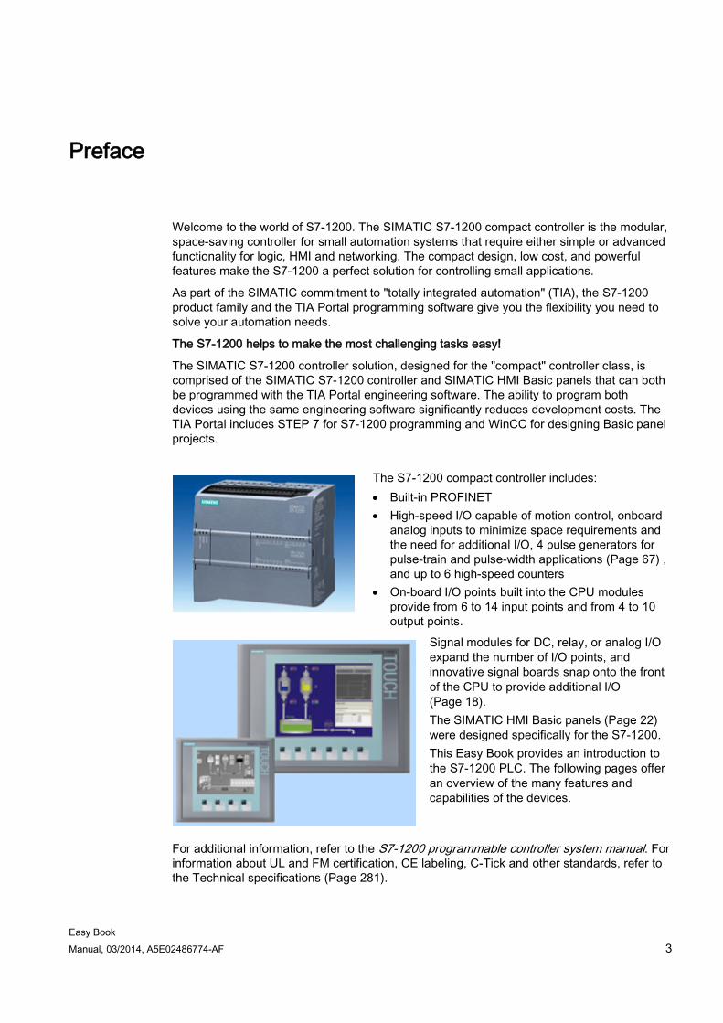
Welcome to the world of S7-1200. The SIMATIC S7-1200 compact controller is the modular, space-saving controller for small automation systems that require either simple or advanced functionality for logic, HMI and networking. The compact design, low cost, and powerful features make the S7-1200 a perfect solution for controlling small applications.
As part of the SIMATIC commitment to "totally integrated automation" (TIA), the S7-1200 product family and the TIA Portal programming software give you the flexibility you need to solve your automation needs.
The S7-1200 helps to make the most challenging tasks easy!
The SIMATIC S7-1200 controller solution, designed for the "compact" controller class, is comprised of the SIMATIC S7-1200 controller and SIMATIC HMI Basic panels that can both be programmed with the TIA Portal engineering software. The ability to program both devices using the same engineering software significantly reduces development costs. The TIA Portal includes STEP 7 for S7-1200 programming and WinCC for designing Basic panel projects.
The S7-1200 compact controller includes: • Built-in PROFINET • High-speed I/O capable of motion control, onboard
analog inputs to minimize space requirements and the need for additional I/O, 4 pulse generators for pulse-train and pulse-width applications (Page 67) , and up to 6 high-speed counters
• On-board I/O points built into the CPU modules provide from 6 to 14 input points and from 4 to 10 output points.
Signal modules for DC, relay, or analog I/O expand the number of I/O points, and innovative signal boards snap onto the front of the CPU to provide additional I/O (Page 18). The SIMATIC HMI Basic panels (Page 22) were designed specifically for the S7-1200. This Easy Book provides an introduction to the S7-1200 PLC. The following pages offer an overview of the many features and capabilities of the devices.
For additional information, refer to the S7-1200 programmable controller system manual. For information about UL and FM certification, CE labeling, C-Tick and other standards, refer to the Technical specifications (Page 281).
Preface
Easy Book 4 Manual, 03/2014, A5E02486774-AF
This manual describes the following products:
● STEP 7 V13 SP1 Basic and Professional
● S7-1200 CPU firmware release V4.0
Documentation and information S7-1200 and STEP 7 provide a variety of documentation and other resources for finding the technical information that you require.
● The S7-1200 system manual provides specific information about the operation, programming, and the specifications for the complete S7-1200 product family. In addition to the system manual, the S7-1200 Easy Book provides a more general overview to the capabilities of the S7-1200 family.
Both the system manual and the Easy Book are available as electronic (PDF) manuals. The electronic manuals can be downloaded from the customer support web site and can also be found on the documentation disk that ships with every S7-1200 CPU.
● The online STEP 7 information system provides immediate access to the conceptual information and specific instructions that describe the operation and functionality of the programming package and basic operation of SIMATIC CPUs.
● My Documentation Manager accesses the electronic (PDF) versions of the SIMATIC documentation set, including the system manual, the Easy Book, and the STEP 7 information system. With My Documentation Manager, you can drag and drop topics from various documents to create your own custom manual.
The customer support entry portal (http://support.automation.siemens.com) provides a link to My Documentation Manager under mySupport.
● The customer support web site also provides podcasts, FAQs, and other helpful documents for S7-1200 and STEP 7. The podcasts utilize short educational video presentations that focus on specific features or scenarios in order to demonstrate the interactions, convenience, and efficiency provided by STEP 7. Visit the following web sites to access the collection of podcasts:
– STEP 7 Basic web page (http://www.automation.siemens.com/mcms/simatic-controller-software/en/step7/step7-basic/Pages/Default.aspx)
– STEP 7 Professional web page (http://www.automation.siemens.com/mcms/simatic-controller-software/en/step7/step7-professional/Pages/Default.aspx)
● You can also follow or join product discussions on the Service & Support technical forum (https://www.automation.siemens.com/WW/forum/guests/Conferences.aspx?Language=en&siteid=csius&treeLang=en&groupid=4000002&extranet=standard&viewreg=WW&nodeid0=34612486). These forums allow you to interact with various product experts.
– Forum for S7-1200 (https://www.automation.siemens.com/WW/forum/guests/Conference.aspx?SortField=LastPostDate&SortOrder=Descending&ForumID=258&Language=en&onlyInternet=False)
– Forum for STEP 7 Basic (https://www.automation.siemens.com/WW/forum/guests/Conference.aspx?SortField=LastPostDate&SortOrder=Descending&ForumID=265&Language=en&onlyInternet=False)
Preface
Easy Book Manual, 03/2014, A5E02486774-AF 5
Service and support In addition to our documentation, Siemens offers technical expertise on the Internet and on the customer support web site (http://www.siemens.com/automation/).
Contact your Siemens distributor or sales office for assistance in answering any technical questions, for training, or for ordering S7 products. Because your sales representatives are technically trained and have the most specific knowledge about your operations, process and industry, as well as about the individual Siemens products that you are using, they can provide the fastest and most efficient answers to any problems you might encounter.
Security information Siemens provides automation and drive products with industrial security functions that support the secure operation of plants or machines. They are an important component in a holistic industrial security concept. With this in mind, our products undergo continuous development. We therefore recommend that you keep yourself informed with respect to our product updates. Please find further information and newsletters on this subject at: (http://support.automation.siemens.com)
To ensure the secure operation of a plant or machine it is also necessary to take suitable preventive action (e.g. cell protection concept) and to integrate the automation and drive components into a state-of-the-art holistic industrial security concept for the entire plant or machine. Any third-party products that may be in use must also be taken into account. Please find further information at: (http://www.siemens.com/industrialsecurity)

Preface
Easy Book 6 Manual, 03/2014, A5E02486774-AF
Easy Book Manual, 03/2014, A5E02486774-AF 7
Table of contents
Preface ................................................................................................................................................... 3
1 Introducing the powerful and flexible S7-1200 ....................................................................................... 15
1.1 Introducing the S7-1200 PLC ....................................................................................................... 15
1.2 Expansion capability of the CPU.................................................................................................. 18
1.3 S7-1200 modules ......................................................................................................................... 21
1.4 Basic HMI panels ......................................................................................................................... 22
1.5 Mounting dimensions and clearance requirements ..................................................................... 23
1.6 New features ................................................................................................................................ 27
2 STEP 7 makes the work easy ............................................................................................................... 29
2.1 Easy to insert instructions into your user program ....................................................................... 30
2.2 Easy access to your favorite instructions from a toolbar ............................................................. 30
2.3 Easy to add inputs or outputs to LAD and FBD instructions ........................................................ 31
2.4 Expandable instructions ............................................................................................................... 31
2.5 Easy to change the operating mode of the CPU ......................................................................... 32
2.6 Easy to modify the appearance and configuration of STEP 7 ..................................................... 33
2.7 Project and global libraries for easy access ................................................................................ 33
2.8 Easy to select a version of an instruction .................................................................................... 34
2.9 Easy to drag and drop between editors ....................................................................................... 34
2.10 Changing the call type for a DB ................................................................................................... 35
2.11 Temporarily disconnecting devices from a network ..................................................................... 36
2.12 Easy to virtually "unplug" modules without losing the configuration ............................................ 37
3 Getting started ...................................................................................................................................... 39
3.1 Create a project............................................................................................................................ 39
3.2 Create tags for the I/O of the CPU ............................................................................................... 40
3.3 Create a simple network in your user program ............................................................................ 41
3.4 Use the PLC tags in the tag table for addressing the instructions ............................................... 43
3.5 Add a "box" instruction ................................................................................................................. 44
3.6 Use the CALCULATE instruction for a complex mathematical equation ..................................... 45
3.7 Add an HMI device to the project ................................................................................................. 47
3.8 Create a network connection between the CPU and HMI device ................................................ 48
3.9 Create an HMI connection to share tags ..................................................................................... 48
Table of contents
Easy Book 8 Manual, 03/2014, A5E02486774-AF
3.10 Create an HMI screen ................................................................................................................. 49
3.11 Select a PLC tag for the HMI element ........................................................................................ 50
4 PLC concepts made easy ..................................................................................................................... 51
4.1 Tasks performed every scan cycle ............................................................................................. 51
4.2 Operating modes of the CPU ...................................................................................................... 52
4.3 Execution of the user program .................................................................................................... 53 4.3.1 Processing the scan cycle in RUN mode .................................................................................... 54 4.3.2 OBs help you structure your user program ................................................................................. 55 4.3.3 Event execution priorities and queuing ....................................................................................... 55
4.4 Memory areas, addressing and data types ................................................................................. 58 4.4.1 Data types supported by the S7-1200 ........................................................................................ 60 4.4.2 Addressing memory areas .......................................................................................................... 62 4.4.3 Accessing a "slice" of a tagged data type ................................................................................... 64 4.4.4 Accessing a tag with an AT overlay ............................................................................................ 65
4.5 Pulse outputs .............................................................................................................................. 67
5 Easy to create the device configuration ................................................................................................. 71
5.1 Detecting the configuration for an unspecified CPU ................................................................... 72
5.2 Adding a CPU to the configuration .............................................................................................. 73
5.3 Changing a device ...................................................................................................................... 74
5.4 Adding modules to the configuration ........................................................................................... 74
5.5 Configuring the operation of the CPU and modules ................................................................... 76 5.5.1 System memory and clock memory provide standard functionality ............................................ 77
5.6 Configuring the IP address of the CPU ....................................................................................... 80
5.7 Protecting access to the CPU or code block is easy .................................................................. 82 5.7.1 Know-how protection ................................................................................................................... 84 5.7.2 Copy protection ........................................................................................................................... 85
6 Programming made easy ...................................................................................................................... 87
6.1 Easy to design your user program .............................................................................................. 87 6.1.1 Use OBs for organizing your user program ................................................................................ 89 6.1.2 FBs and FCs make programming the modular tasks easy ......................................................... 90 6.1.3 Data blocks provide easy storage for program data ................................................................... 92 6.1.4 Creating a new code block .......................................................................................................... 92 6.1.5 Creating reusable code blocks .................................................................................................... 93 6.1.6 Calling a code block from another code block ............................................................................ 94
6.2 Easy-to-use programming languages ......................................................................................... 94 6.2.1 Ladder logic (LAD) ...................................................................................................................... 94 6.2.2 Function Block Diagram (FBD) ................................................................................................... 95 6.2.3 SCL overview .............................................................................................................................. 96 6.2.4 SCL program editor ..................................................................................................................... 96
6.3 Powerful instructions make programming easy .......................................................................... 98 6.3.1 Providing the basic instructions you expect ................................................................................ 98 6.3.2 Compare and Move instructions ............................................................................................... 100 6.3.3 Conversion instructions ............................................................................................................. 101
Table of contents
Easy Book Manual, 03/2014, A5E02486774-AF 9
6.3.4 Math made easy with the Calculate instruction ......................................................................... 103 6.3.5 Timers ........................................................................................................................................ 104 6.3.6 Counters ..................................................................................................................................... 109 6.3.7 Pulse-width modulation (PWM) .................................................................................................. 111
6.4 Easy to create data logs ............................................................................................................ 112
6.5 Easy to monitor and test your user program .............................................................................. 114 6.5.1 Watch tables and force tables .................................................................................................... 114 6.5.2 Cross reference to show usage ................................................................................................. 115 6.5.3 Call structure to examine the calling hierarchy .......................................................................... 116 6.5.4 Diagnostic instructions to monitor the hardware ........................................................................ 117 6.5.4.1 Reading the states of the LEDs on the CPU ............................................................................. 117 6.5.4.2 Instructions for reading the diagnostic status of the devices ..................................................... 117
6.6 High-speed counter (HSC) ......................................................................................................... 118 6.6.1 Operation of the high-speed counter ......................................................................................... 119 6.6.2 Configuration of the HSC ........................................................................................................... 125
7 Easy to communicate between devices ............................................................................................... 127
7.1 Creating a network connection .................................................................................................. 128
7.2 Communication options ............................................................................................................. 129
7.3 Number of asynchronous communication connections ............................................................. 131
7.4 PROFINET and PROFIBUS instructions ................................................................................... 132
7.5 PROFINET ................................................................................................................................. 133 7.5.1 Open user communication ......................................................................................................... 133 7.5.1.1 Ad hoc mode .............................................................................................................................. 134 7.5.1.2 Connection IDs for the Open user communication instructions ................................................. 134 7.5.1.3 Parameters for the PROFINET connection ............................................................................... 137 7.5.2 Configuring the Local/Partner connection path .......................................................................... 140
7.6 PROFIBUS ................................................................................................................................. 142 7.6.1 Communications services of the PROFIBUS CMs .................................................................... 144 7.6.2 Reference to the PROFIBUS CM user manuals ........................................................................ 145 7.6.3 Adding the CM 1243-5 (DP master) module and a DP slave .................................................... 145 7.6.4 Assigning PROFIBUS addresses to the CM 1243-5 module and DP slave .............................. 146
7.7 AS-i ............................................................................................................................................ 148 7.7.1 Adding the AS-i master CM 1243-2 and AS-i slave ................................................................... 149 7.7.2 Assigning an AS-i address to an AS-i slave .............................................................................. 150
7.8 S7 communication ..................................................................................................................... 153 7.8.1 GET and PUT instructions ......................................................................................................... 153 7.8.2 Creating an S7 connection ......................................................................................................... 154 7.8.3 GET/PUT connection parameter assignment ............................................................................ 155
7.9 GPRS ......................................................................................................................................... 156 7.9.1 Connection to a GSM network ................................................................................................... 156
7.10 PtP, USS, and Modbus communication protocols ..................................................................... 163 7.10.1 Point-to-point communication .................................................................................................... 163 7.10.2 Using the serial communication interfaces ................................................................................ 163 7.10.3 PtP instructions .......................................................................................................................... 164 7.10.4 USS instructions......................................................................................................................... 165
Table of contents
Easy Book 10 Manual, 03/2014, A5E02486774-AF
7.10.5 Modbus instructions .................................................................................................................. 167
8 PID is easy .......................................................................................................................................... 169
8.1 Inserting the PID instruction and technology object .................................................................. 171
8.2 PID_Compact instruction ........................................................................................................... 173
8.3 PID_Compact instruction ErrorBit parameters .......................................................................... 177
8.4 PID_3Step instruction ................................................................................................................ 179
8.5 PID_3Step instruction ErrorBit parameters ............................................................................... 186
8.6 Configuring the PID controller ................................................................................................... 188
8.7 Commissioning the PID controller ............................................................................................. 190
9 Web server for easy Internet connectivity ............................................................................................. 193
9.1 Easy to use the standard Web pages ....................................................................................... 194
9.2 Constraints that can affect the use of the Web server .............................................................. 196 9.2.1 Feature restrictions when the Internet options disable JavaScript ........................................... 197 9.2.2 Feature restrictions when the Internet options do not allow cookies ........................................ 198
9.3 Easy to create user-defined web pages .................................................................................... 198 9.3.1 Easy to create custom "user-defined" web pages .................................................................... 198 9.3.2 Constraints specific to user-defined Web pages....................................................................... 199 9.3.3 Configuration of a user-defined Web page ............................................................................... 200 9.3.4 Using the WWW instruction ...................................................................................................... 201
10 Motion control is easy .......................................................................................................................... 203
10.1 Phasing ..................................................................................................................................... 208
10.2 Configuring a pulse generator ................................................................................................... 210
10.3 Configuring the axis .................................................................................................................. 211
10.4 Configuring the TO_CommandTable_PTO ............................................................................... 214
10.5 Motion control instructions ........................................................................................................ 217 10.5.1 MC instruction overview ............................................................................................................ 217 10.5.2 MC_Power (Release/block axis) instruction .............................................................................. 217 10.5.3 MC_Reset (Confirm error) instruction ....................................................................................... 221 10.5.4 MC_Home (Home axis) instruction ........................................................................................... 222 10.5.5 MC_Halt (Pause axis) instruction .............................................................................................. 224 10.5.6 MC_MoveAbsolute (Position axis absolutely) instruction ......................................................... 226 10.5.7 MC_MoveRelative (Position axis relatively) instruction ............................................................ 228 10.5.8 MC_MoveVelocity (Move axis at predefined velocity) instruction ............................................. 230 10.5.9 MC_MoveJog (Move axis in jog mode) instruction ................................................................... 233 10.5.10 MC_CommandTable (Run axis commans as movement sequence) instruction ...................... 235 10.5.11 MC_ChangeDynamic (Change dynamc settings for the axis) instruction ................................. 237 10.5.12 MC_WriteParam (write parameters of a technology object) instruction .................................... 239 10.5.13 MC_ReadParam instruction (read parameters of a technology object) instruction .................. 241
10.6 Operation of motion control for S7-1200 ................................................................................... 242 10.6.1 CPU outputs used for motion control ........................................................................................ 242 10.6.2 Hardware and software limit switches for motion control .......................................................... 244 10.6.3 Homing ...................................................................................................................................... 247 10.6.3.1 Homing the axis ........................................................................................................................ 247
Table of contents
Easy Book Manual, 03/2014, A5E02486774-AF 11
10.6.3.2 Configuration of homing parameters ......................................................................................... 249 10.6.3.3 Sequence for active homing ...................................................................................................... 251
10.7 Commissioning........................................................................................................................... 252
11 Easy to use the online tools................................................................................................................. 257
11.1 Going online and connecting to a CPU ...................................................................................... 257
11.2 Interacting with the online CPU .................................................................................................. 258
11.3 Going online to monitor the values in the CPU .......................................................................... 259
11.4 Displaying status of the user program is easy ........................................................................... 260
11.5 Using a watch table for monitoring the CPU .............................................................................. 260
11.6 Using the force table .................................................................................................................. 261
11.7 Capturing the online values of a DB to reset the start values .................................................... 264
11.8 Copying elements of the project ................................................................................................ 265
11.9 Comparing offline and online CPUs ........................................................................................... 266
11.10 Displaying the diagnostic events ................................................................................................ 267
11.11 Setting the IP address and time of day ...................................................................................... 267
11.12 Resetting to factory settings ....................................................................................................... 268
11.13 Updating firmware ...................................................................................................................... 269
11.14 Downloading an IP address to an online CPU ........................................................................... 270
11.15 Using the "unspecified CPU" to upload the hardware configuration .......................................... 271
11.16 Downloading in RUN mode ........................................................................................................ 272 11.16.1 Changing your program in RUN mode ...................................................................................... 273
11.17 Tracing and recording CPU data on trigger conditions .............................................................. 274
12 IO-Link is easy .................................................................................................................................... 275
12.1 Overview of IO-Link technology ................................................................................................. 275
12.2 Components of an IO-Link system............................................................................................. 275
12.3 After power-up............................................................................................................................ 275
12.4 IO-Link protocol .......................................................................................................................... 276
12.5 Configuration in the fieldbus ...................................................................................................... 276
12.6 IO-Link and your STEP 7 program............................................................................................. 276
12.7 The SM 1278 4xIO-Link Master ................................................................................................. 277
A Technical specifications ...................................................................................................................... 281
A.1 General technical specifications ................................................................................................ 281
A.2 CPU modules ............................................................................................................................. 289
A.3 Digital I/O modules ..................................................................................................................... 293 A.3.1 SB 1221, SB 1222, and SB 1223 digital input/output (DI, DQ, and DI/DQ)............................... 293 A.3.2 SM 1221 digital input (DI) .......................................................................................................... 296 A.3.3 SM 1222 digital output (DQ) ...................................................................................................... 297
Table of contents
Easy Book 12 Manual, 03/2014, A5E02486774-AF
A.3.4 SM 1223 VDC digital input/output (DI / DQ) ............................................................................. 299 A.3.5 SM 1223 120/230 VAC input / Relay output ............................................................................. 300
A.4 Specifications for the digital inputs and outputs ........................................................................ 302 A.4.1 24 VDC digital inputs (DI) .......................................................................................................... 302 A.4.2 120/230 VAC digital AC inputs .................................................................................................. 303 A.4.3 Digital outputs (DQ) ................................................................................................................... 304
A.5 Analog I/O modules ................................................................................................................... 306 A.5.1 SB 1231 and SB 1232 analog input (AI) and output (AQ) ........................................................ 306 A.5.2 SM 1231 analog input (AI) ........................................................................................................ 307 A.5.3 SM 1232 analog output (AQ) .................................................................................................... 308 A.5.4 SM 1234 analog input/output (AI/AQ) ....................................................................................... 308 A.5.5 Wiring diagrams for SM 1231 (AI), SM 1232 (AQ), and SM 1234 (AI/AQ) ............................... 309
A.6 BB 1297 battery board .............................................................................................................. 310
A.7 Specifications for the analog I/O ............................................................................................... 311 A.7.1 Specifications for the analog inputs (CPU, SM, and SB) .......................................................... 311 A.7.2 Input (AI) measurement ranges for voltage and current ........................................................... 312 A.7.3 Step response for the analog inputs (AI) .................................................................................. 313 A.7.4 Sample time and update times for the analog inputs ................................................................ 314 A.7.5 Specifications for the analog outputs ........................................................................................ 315 A.7.6 Output (AQ) measurement ranges for voltage and current ...................................................... 315
A.8 RTD and Thermocouple modules ............................................................................................. 317 A.8.1 SB 1231 RTD and SB 1231 TC specifications.......................................................................... 318 A.8.2 SM 1231 RTD specifications ..................................................................................................... 319 A.8.3 SM 1231 TC specifications ....................................................................................................... 321 A.8.4 Analog input specifications for RTD and TC (SM and SB) ....................................................... 323 A.8.5 Thermocouple type ................................................................................................................... 324 A.8.6 Thermocouple filter selection and update times ....................................................................... 325 A.8.7 RTD sensor type selection table ............................................................................................... 326 A.8.8 RTD filter selection and update times ....................................................................................... 327
A.9 Communication interfaces ......................................................................................................... 328 A.9.1 PROFIBUS master/slave .......................................................................................................... 328 A.9.1.1 CM 1242-5 PROFIBUS slave.................................................................................................... 328 A.9.1.2 CM 1243-5 PROFIBUS master ................................................................................................. 329 A.9.2 GPRS CP .................................................................................................................................. 331 A.9.2.1 Technical specifications of the CP 1242-7 GPRS .................................................................... 331 A.9.3 Teleservice (TS) ........................................................................................................................ 334 A.9.4 RS485, RS232 and RS422 communication .............................................................................. 334 A.9.4.1 CB 1241 RS485 specifications.................................................................................................. 334 A.9.4.2 CM 1241 RS422/485 specifications .......................................................................................... 337 A.9.4.3 CM 1241 RS232 specifications ................................................................................................. 338
A.10 Technology modules ................................................................................................................. 339 A.10.1 SM 1278 4xIO-Link Master SM ................................................................................................. 339 A.10.1.1 SM 1278 4xIO-Link Master signal module specifications ......................................................... 339 A.10.1.2 SM 1278 4xIO-Link Master SM wiring diagrams....................................................................... 342
A.11 Companion products ................................................................................................................. 343 A.11.1 PM 1207 power module ............................................................................................................ 343 A.11.2 CSM 1277 compact switch module ........................................................................................... 343 A.11.3 CM CANopen module ............................................................................................................... 344

Table of contents
Easy Book Manual, 03/2014, A5E02486774-AF 13
B Exchanging a V3.0 CPU for a V4.0 CPU ............................................................................................. 345
B.1 Exchanging a V3.0 CPU for a V4.0 CPU ................................................................................... 345
Index................................................................................................................................................... 349

Table of contents
Easy Book 14 Manual, 03/2014, A5E02486774-AF
Easy Book Manual, 03/2014, A5E02486774-AF 15
Introducing the powerful and flexible S7-1200 1 1.1 Introducing the S7-1200 PLC
The S7-1200 controller provides the flexibility and power to control a wide variety of devices in support of your automation needs. The compact design, flexible configuration, and powerful instruction set combine to make the S7-1200 a perfect solution for controlling a wide variety of applications.
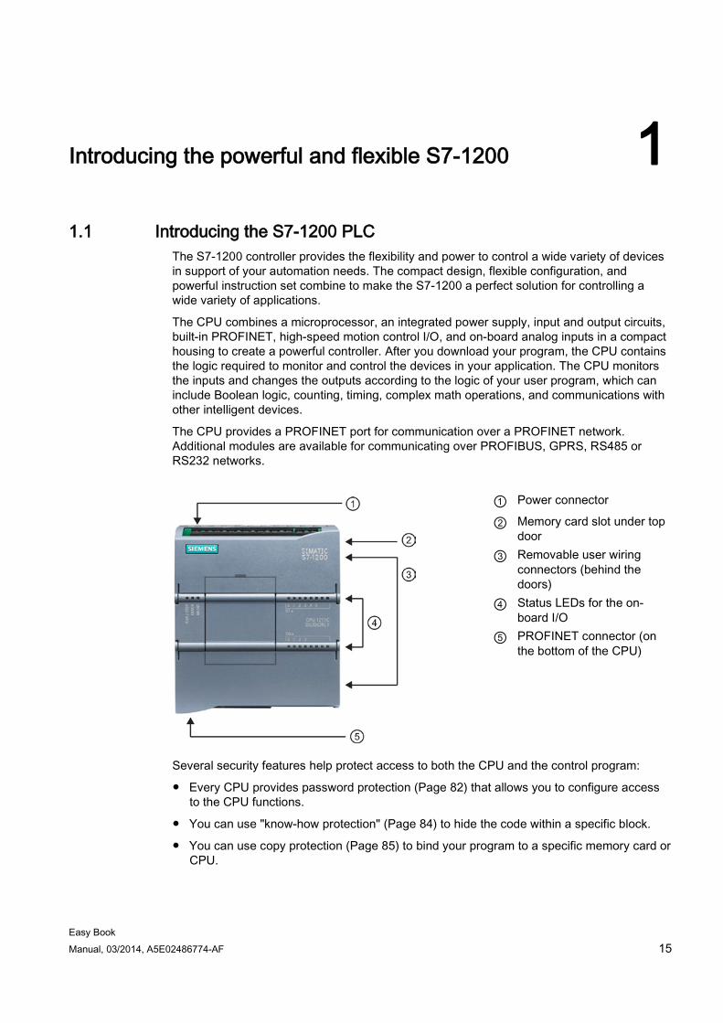
The CPU combines a microprocessor, an integrated power supply, input and output circuits, built-in PROFINET, high-speed motion control I/O, and on-board analog inputs in a compact housing to create a powerful controller. After you download your program, the CPU contains the logic required to monitor and control the devices in your application. The CPU monitors the inputs and changes the outputs according to the logic of your user program, which can include Boolean logic, counting, timing, complex math operations, and communications with other intelligent devices.
The CPU provides a PROFINET port for communication over a PROFINET network. Additional modules are available for communicating over PROFIBUS, GPRS, RS485 or RS232 networks.
① Power connector
② Memory card slot under top door
③ Removable user wiring connectors (behind the doors)
④ Status LEDs for the on-board I/O
⑤ PROFINET connector (on the bottom of the CPU)
Several security features help protect access to both the CPU and the control program:
● Every CPU provides password protection (Page 82) that allows you to configure access to the CPU functions.
● You can use "know-how protection" (Page 84) to hide the code within a specific block.
● You can use copy protection (Page 85) to bind your program to a specific memory card or CPU.
Introducing the powerful and flexible S7-1200 1.1 Introducing the S7-1200 PLC
Easy Book 16 Manual, 03/2014, A5E02486774-AF
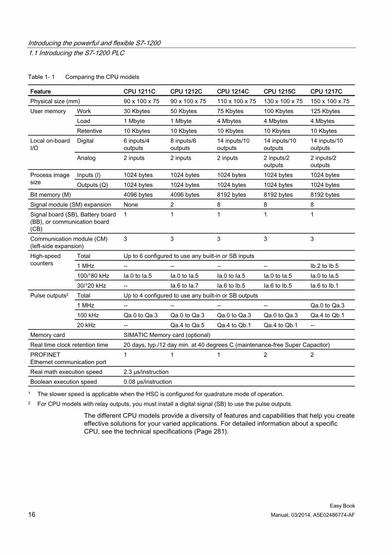
Table 1- 1 Comparing the CPU models
Feature CPU 1211C CPU 1212C CPU 1214C CPU 1215C CPU 1217C Physical size (mm) 90 x 100 x 75 90 x 100 x 75 110 x 100 x 75 130 x 100 x 75 150 x 100 x 75 User memory Work 30 Kbytes 50 Kbytes 75 Kbytes 100 Kbytes 125 Kbytes
Load 1 Mbyte 1 Mbyte 4 Mbytes 4 Mbytes 4 Mbytes Retentive 10 Kbytes 10 Kbytes 10 Kbytes 10 Kbytes 10 Kbytes
Local on-board I/O
Digital 6 inputs/4 outputs
8 inputs/6 outputs
14 inputs/10 outputs
14 inputs/10 outputs
14 inputs/10 outputs
Analog 2 inputs 2 inputs 2 inputs 2 inputs/2 outputs
2 inputs/2 outputs
Process image size
Inputs (I) 1024 bytes 1024 bytes 1024 bytes 1024 bytes 1024 bytes Outputs (Q) 1024 bytes 1024 bytes 1024 bytes 1024 bytes 1024 bytes
Bit memory (M) 4096 bytes 4096 bytes 8192 bytes 8192 bytes 8192 bytes Signal module (SM) expansion None 2 8 8 8 Signal board (SB), Battery board (BB), or communication board (CB)
1 1 1 1 1
Communication module (CM) (left-side expansion)
3 3 3 3 3
High-speed counters
Total Up to 6 configured to use any built-in or SB inputs 1 MHz -- -- -- -- Ib.2 to Ib.5 100/180 kHz Ia.0 to Ia.5 Ia.0 to Ia.5 Ia.0 to Ia.5 Ia.0 to Ia.5 Ia.0 to Ia.5 30/120 kHz -- Ia.6 to Ia.7 Ia.6 to Ib.5 Ia.6 to Ib.5 Ia.6 to Ib.1
Pulse outputs2 Total Up to 4 configured to use any built-in or SB outputs 1 MHz -- -- -- -- Qa.0 to Qa.3 100 kHz Qa.0 to Qa.3 Qa.0 to Qa.3 Qa.0 to Qa.3 Qa.0 to Qa.3 Qa.4 to Qb.1 20 kHz -- Qa.4 to Qa.5 Qa.4 to Qb.1 Qa.4 to Qb.1 --
Memory card SIMATIC Memory card (optional) Real time clock retention time 20 days, typ./12 day min. at 40 degrees C (maintenance-free Super Capacitor) PROFINET Ethernet communication port
1 1 1 2 2
Real math execution speed 2.3 μs/instruction Boolean execution speed 0.08 μs/instruction 1 The slower speed is applicable when the HSC is configured for quadrature mode of operation.
2 For CPU models with relay outputs, you must install a digital signal (SB) to use the pulse outputs.
The different CPU models provide a diversity of features and capabilities that help you create effective solutions for your varied applications. For detailed information about a specific CPU, see the technical specifications (Page 281).
Introducing the powerful and flexible S7-1200 1.1 Introducing the S7-1200 PLC
Easy Book Manual, 03/2014, A5E02486774-AF 17
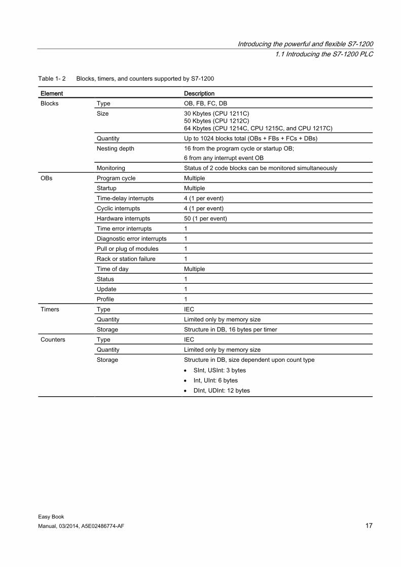
Table 1- 2 Blocks, timers, and counters supported by S7-1200
Element Description Blocks Type OB, FB, FC, DB
Size 30 Kbytes (CPU 1211C) 50 Kbytes (CPU 1212C) 64 Kbytes (CPU 1214C, CPU 1215C, and CPU 1217C)
Quantity Up to 1024 blocks total (OBs + FBs + FCs + DBs) Nesting depth 16 from the program cycle or startup OB;
6 from any interrupt event OB Monitoring Status of 2 code blocks can be monitored simultaneously
OBs Program cycle Multiple Startup Multiple Time-delay interrupts 4 (1 per event) Cyclic interrupts 4 (1 per event) Hardware interrupts 50 (1 per event) Time error interrupts 1 Diagnostic error interrupts 1 Pull or plug of modules 1 Rack or station failure 1 Time of day Multiple Status 1 Update 1 Profile 1
Timers Type IEC Quantity Limited only by memory size Storage Structure in DB, 16 bytes per timer
Counters Type IEC Quantity Limited only by memory size Storage Structure in DB, size dependent upon count type
• SInt, USInt: 3 bytes • Int, UInt: 6 bytes • DInt, UDInt: 12 bytes
Introducing the powerful and flexible S7-1200 1.2 Expansion capability of the CPU
Easy Book 18 Manual, 03/2014, A5E02486774-AF
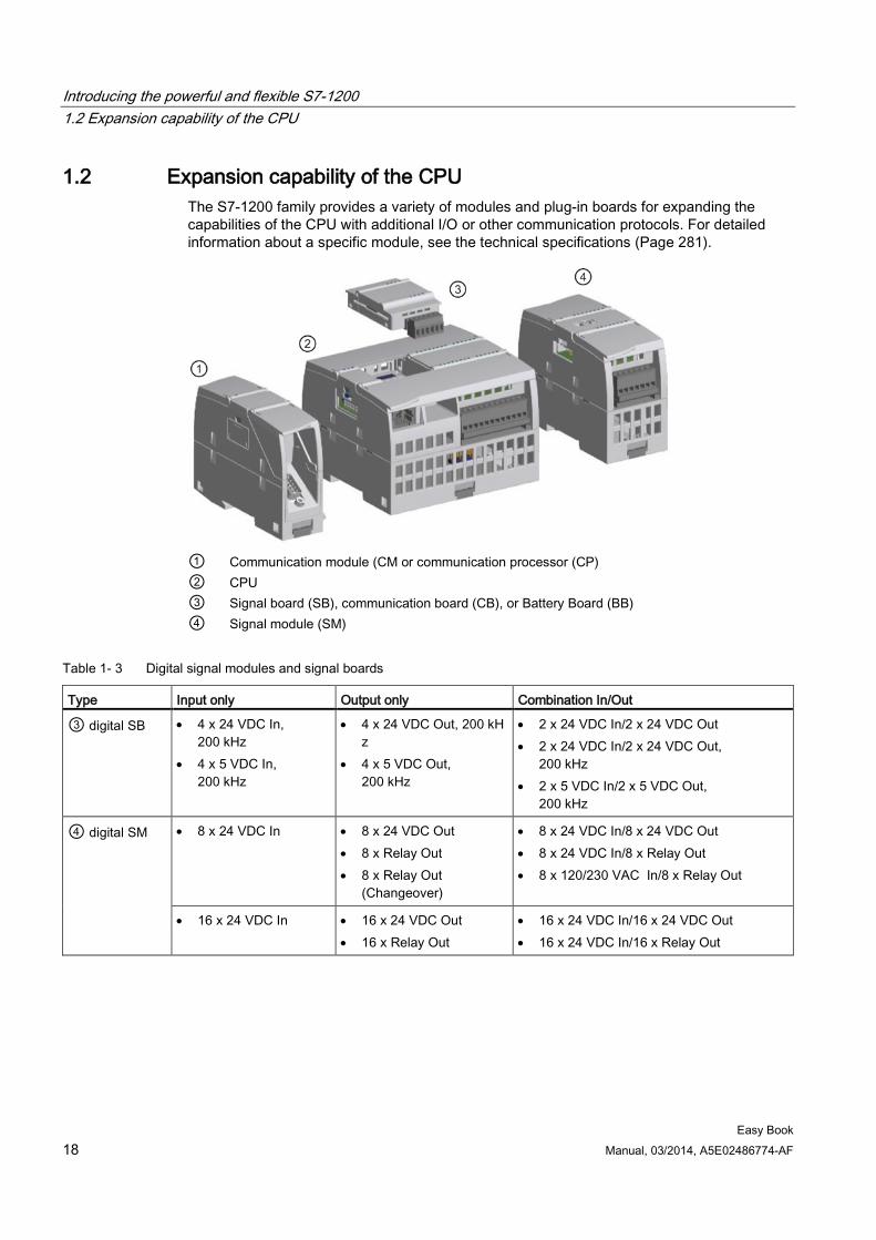
1.2 Expansion capability of the CPU The S7-1200 family provides a variety of modules and plug-in boards for expanding the capabilities of the CPU with additional I/O or other communication protocols. For detailed information about a specific module, see the technical specifications (Page 281).
① Communication module (CM or communication processor (CP) ② CPU ③ Signal board (SB), communication board (CB), or Battery Board (BB) ④ Signal module (SM)
Table 1- 3 Digital signal modules and signal boards
Type Input only Output only Combination In/Out
③ digital SB • 4 x 24 VDC In, 200 kHz
• 4 x 5 VDC In, 200 kHz
• 4 x 24 VDC Out, 200 kHz
• 4 x 5 VDC Out, 200 kHz
• 2 x 24 VDC In/2 x 24 VDC Out • 2 x 24 VDC In/2 x 24 VDC Out,
200 kHz • 2 x 5 VDC In/2 x 5 VDC Out,
200 kHz
④ digital SM • 8 x 24 VDC In • 8 x 24 VDC Out • 8 x Relay Out • 8 x Relay Out
(Changeover)
• 8 x 24 VDC In/8 x 24 VDC Out • 8 x 24 VDC In/8 x Relay Out • 8 x 120/230 VAC In/8 x Relay Out
• 16 x 24 VDC In • 16 x 24 VDC Out • 16 x Relay Out
• 16 x 24 VDC In/16 x 24 VDC Out • 16 x 24 VDC In/16 x Relay Out
Introducing the powerful and flexible S7-1200 1.2 Expansion capability of the CPU
Easy Book Manual, 03/2014, A5E02486774-AF 19
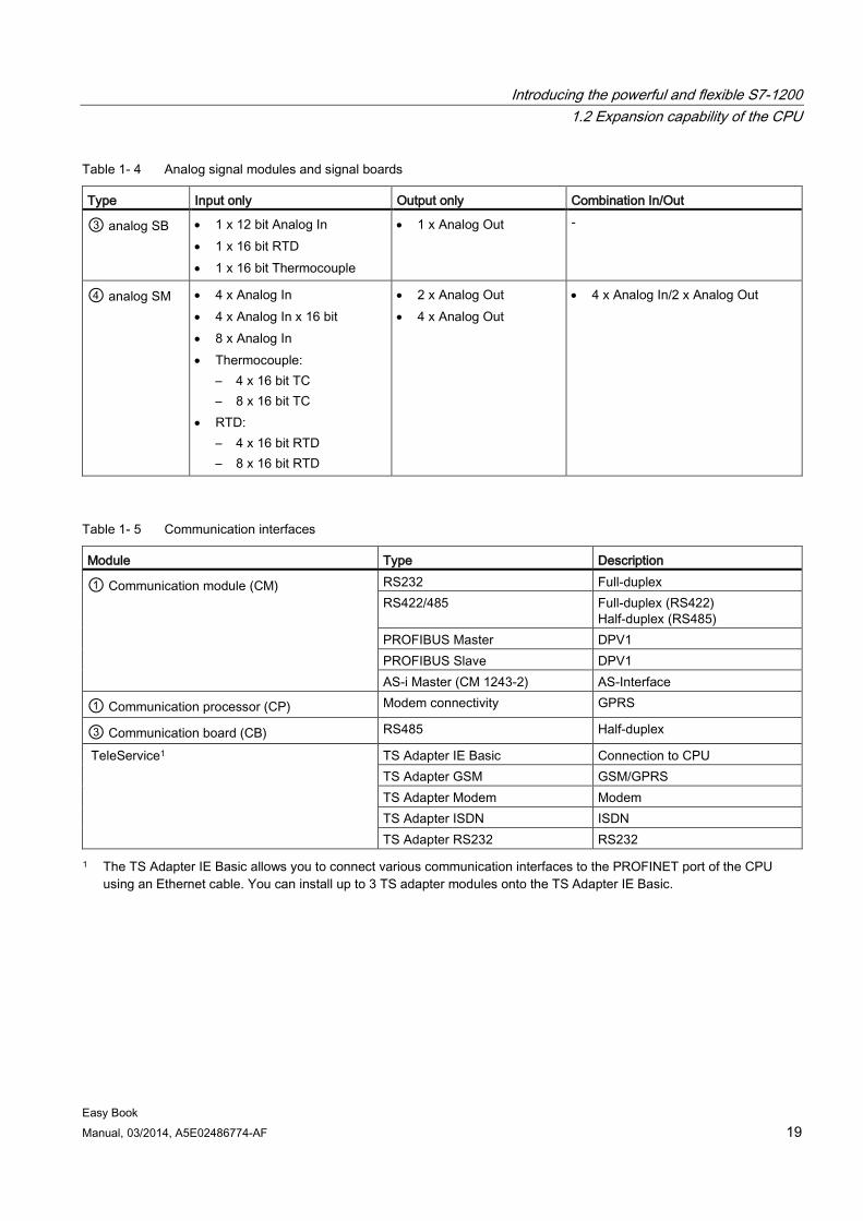
Table 1- 4 Analog signal modules and signal boards
Type Input only Output only Combination In/Out
③ analog SB • 1 x 12 bit Analog In • 1 x 16 bit RTD • 1 x 16 bit Thermocouple
• 1 x Analog Out -
④ analog SM • 4 x Analog In • 4 x Analog In x 16 bit • 8 x Analog In • Thermocouple:
– 4 x 16 bit TC – 8 x 16 bit TC
• RTD: – 4 x 16 bit RTD – 8 x 16 bit RTD
• 2 x Analog Out • 4 x Analog Out
• 4 x Analog In/2 x Analog Out
Table 1- 5 Communication interfaces
Module Type Description
① Communication module (CM) RS232 Full-duplex RS422/485 Full-duplex (RS422)
Half-duplex (RS485) PROFIBUS Master DPV1 PROFIBUS Slave DPV1 AS-i Master (CM 1243-2) AS-Interface
① Communication processor (CP) Modem connectivity GPRS
③ Communication board (CB) RS485 Half-duplex
TeleService1 TS Adapter IE Basic Connection to CPU TS Adapter GSM GSM/GPRS TS Adapter Modem Modem TS Adapter ISDN ISDN TS Adapter RS232 RS232
1 The TS Adapter IE Basic allows you to connect various communication interfaces to the PROFINET port of the CPU using an Ethernet cable. You can install up to 3 TS adapter modules onto the TS Adapter IE Basic.
Introducing the powerful and flexible S7-1200 1.2 Expansion capability of the CPU
Easy Book 20 Manual, 03/2014, A5E02486774-AF
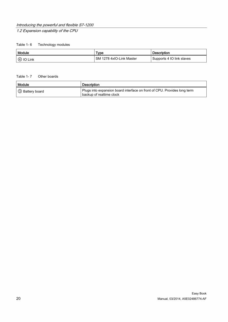
Table 1- 6 Technology modules
Module Type Description
④ IO Link SM 1278 4xIO-Link Master Supports 4 IO link slaves
Table 1- 7 Other boards
Module Description
③ Battery board Plugs into expansion board interface on front of CPU. Provides long term backup of realtime clock
Introducing the powerful and flexible S7-1200 1.3 S7-1200 modules
Easy Book Manual, 03/2014, A5E02486774-AF 21
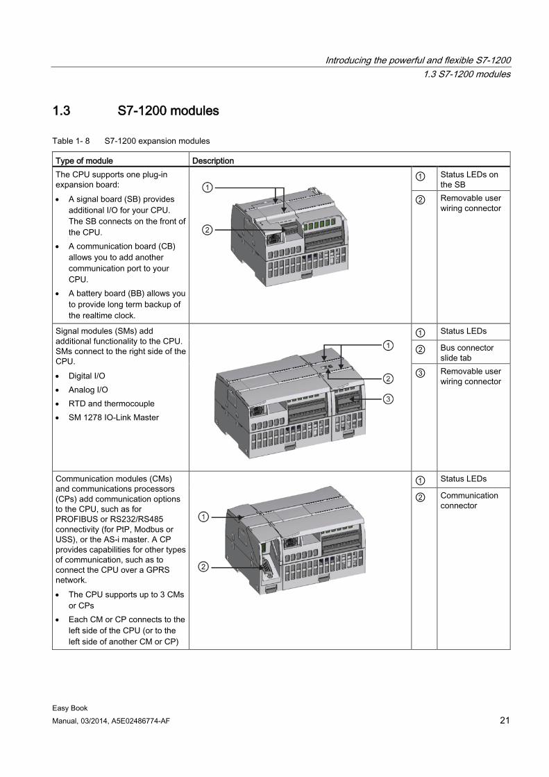
1.3 S7-1200 modules
Table 1- 8 S7-1200 expansion modules
Type of module Description The CPU supports one plug-in expansion board: • A signal board (SB) provides
additional I/O for your CPU. The SB connects on the front of the CPU.
• A communication board (CB) allows you to add another communication port to your CPU.
• A battery board (BB) allows you to provide long term backup of the realtime clock.
① Status LEDs on the SB
② Removable user wiring connector
Signal modules (SMs) add additional functionality to the CPU. SMs connect to the right side of the CPU. • Digital I/O • Analog I/O • RTD and thermocouple • SM 1278 IO-Link Master
① Status LEDs
② Bus connector slide tab
③ Removable user wiring connector
Communication modules (CMs) and communications processors (CPs) add communication options to the CPU, such as for PROFIBUS or RS232/RS485 connectivity (for PtP, Modbus or USS), or the AS-i master. A CP provides capabilities for other types of communication, such as to connect the CPU over a GPRS network. • The CPU supports up to 3 CMs
or CPs • Each CM or CP connects to the
left side of the CPU (or to the left side of another CM or CP)
① Status LEDs
② Communication connector
Introducing the powerful and flexible S7-1200 1.4 Basic HMI panels
Easy Book 22 Manual, 03/2014, A5E02486774-AF
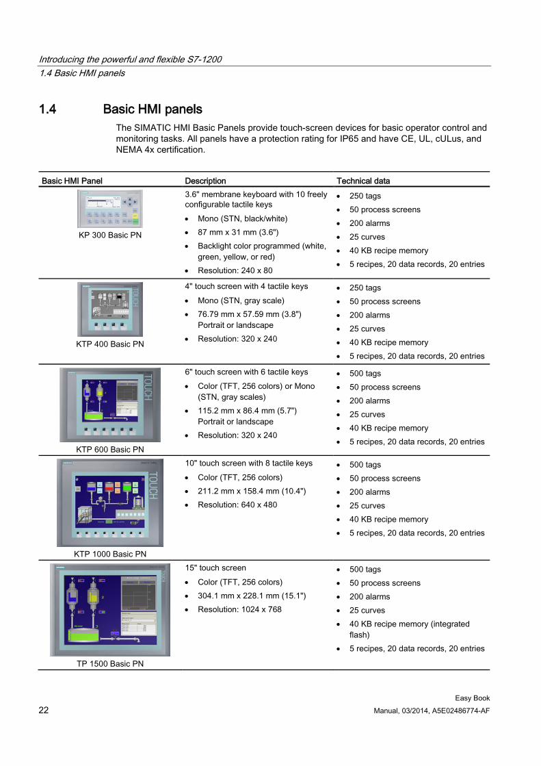
1.4 Basic HMI panels The SIMATIC HMI Basic Panels provide touch-screen devices for basic operator control and monitoring tasks. All panels have a protection rating for IP65 and have CE, UL, cULus, and NEMA 4x certification.
Basic HMI Panel Description Technical data
KP 300 Basic PN
3.6" membrane keyboard with 10 freely configurable tactile keys • Mono (STN, black/white) • 87 mm x 31 mm (3.6") • Backlight color programmed (white,
green, yellow, or red) • Resolution: 240 x 80
• 250 tags • 50 process screens • 200 alarms • 25 curves • 40 KB recipe memory • 5 recipes, 20 data records, 20 entries
KTP 400 Basic PN
4" touch screen with 4 tactile keys • Mono (STN, gray scale) • 76.79 mm x 57.59 mm (3.8")
Portrait or landscape • Resolution: 320 x 240
• 250 tags • 50 process screens • 200 alarms • 25 curves • 40 KB recipe memory • 5 recipes, 20 data records, 20 entries
KTP 600 Basic PN
6" touch screen with 6 tactile keys • Color (TFT, 256 colors) or Mono
(STN, gray scales) • 115.2 mm x 86.4 mm (5.7")
Portrait or landscape • Resolution: 320 x 240
• 500 tags • 50 process screens • 200 alarms • 25 curves • 40 KB recipe memory • 5 recipes, 20 data records, 20 entries
KTP 1000 Basic PN
10" touch screen with 8 tactile keys • Color (TFT, 256 colors) • 211.2 mm x 158.4 mm (10.4") • Resolution: 640 x 480
• 500 tags • 50 process screens • 200 alarms • 25 curves • 40 KB recipe memory • 5 recipes, 20 data records, 20 entries
TP 1500 Basic PN
15" touch screen • Color (TFT, 256 colors) • 304.1 mm x 228.1 mm (15.1") • Resolution: 1024 x 768
• 500 tags • 50 process screens • 200 alarms • 25 curves • 40 KB recipe memory (integrated
flash) • 5 recipes, 20 data records, 20 entries
Introducing the powerful and flexible S7-1200 1.5 Mounting dimensions and clearance requirements
Easy Book Manual, 03/2014, A5E02486774-AF 23
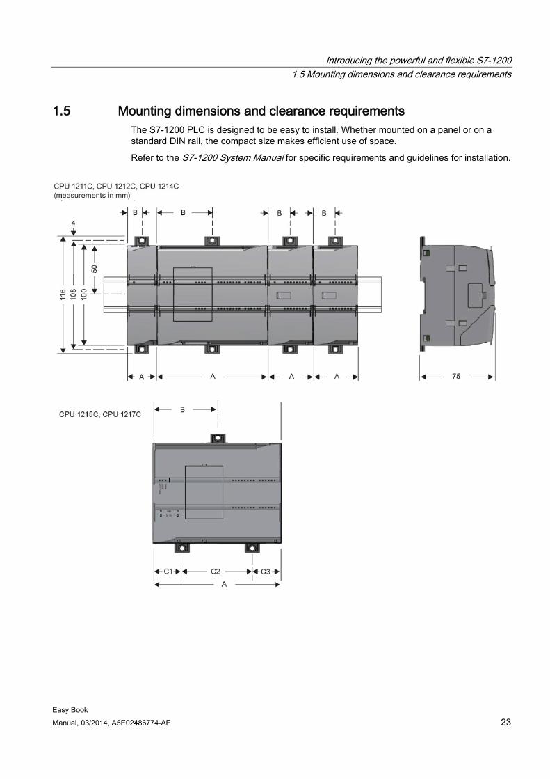
1.5 Mounting dimensions and clearance requirements The S7-1200 PLC is designed to be easy to install. Whether mounted on a panel or on a standard DIN rail, the compact size makes efficient use of space.
Refer to the S7-1200 System Manual for specific requirements and guidelines for installation.
Introducing the powerful and flexible S7-1200 1.5 Mounting dimensions and clearance requirements
Easy Book 24 Manual, 03/2014, A5E02486774-AF
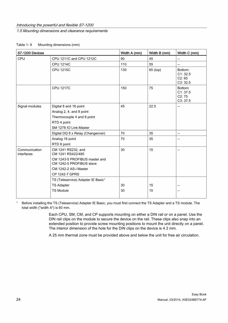
Table 1- 9 Mounting dimensions (mm)
S7-1200 Devices Width A (mm) Width B (mm) Width C (mm) CPU CPU 1211C and CPU 1212C 90 45 --
CPU 1214C 110 55 -- CPU 1215C 130 65 (top) Bottom:
C1: 32.5 C2: 65 C3: 32.5
CPU 1217C 150 75 Bottom: C1: 37.5 C2: 75 C3: 37.5
Signal modules Digital 8 and 16 point Analog 2, 4, and 8 point Thermocouple 4 and 8 point RTD 4 point SM 1278 IO Link-Master
45 22.5 --
Digital DQ 8 x Relay (Changeover) 70 35 -- Analog 16 point RTD 8 point
70 35 --
Communication interfaces
CM 1241 RS232, and CM 1241 RS422/485 CM 1243-5 PROFIBUS master and CM 1242-5 PROFIBUS slave CM 1242-2 AS-i Master CP 1242-7 GPRS
30 15 --
TS (Teleservice) Adapter IE Basic1 TS Adapter TS Module
30 30
15 15
-- --
1 Before installing the TS (Teleservice) Adapter IE Basic, you must first connect the TS Adapter and a TS module. The total width ("width A") is 60 mm.
Each CPU, SM, CM, and CP supports mounting on either a DIN rail or on a panel. Use the DIN rail clips on the module to secure the device on the rail. These clips also snap into an extended position to provide screw mounting positions to mount the unit directly on a panel. The interior dimension of the hole for the DIN clips on the device is 4.3 mm.
A 25 mm thermal zone must be provided above and below the unit for free air circulation.
Introducing the powerful and flexible S7-1200 1.5 Mounting dimensions and clearance requirements
Easy Book Manual, 03/2014, A5E02486774-AF 25
The S7-1200 equipment is designed to be easy to install. You can install an S7-1200 either on a panel or on a standard rail, and you can orient the S7-1200 either horizontally or vertically. The small size of the S7-1200 allows you to make efficient use of space.
WARNING
Installation requirements for S7-1200 PLCs
The SIMATIC S7-1200 PLCs are Open Type Controllers. It is required that you install the S7-1200 in a housing, cabinet, or electric control room. Entry to the housing, cabinet, or electric control room should be limited to authorized personnel.
Failure to follow these installation requirements could result in death, severe personal injury and/or property damage.
Always follow these requirements when installing S7-1200 PLCs.
Separate the S7-1200 devices from heat, high voltage, and electrical noise As a general rule for laying out the devices of your system, always separate the devices that generate high voltage and high electrical noise from the low-voltage, logic-type devices such as the S7-1200.
When configuring the layout of the S7-1200 inside your panel, consider the heat-generating devices and locate the electronic-type devices in the cooler areas of your cabinet. Reducing the exposure to a high-temperature environment will extend the operating life of any electronic device.
Consider also the routing of the wiring for the devices in the panel. Avoid placing low-voltage signal wires and communications cables in the same tray with AC power wiring and high-energy, rapidly-switched DC wiring.
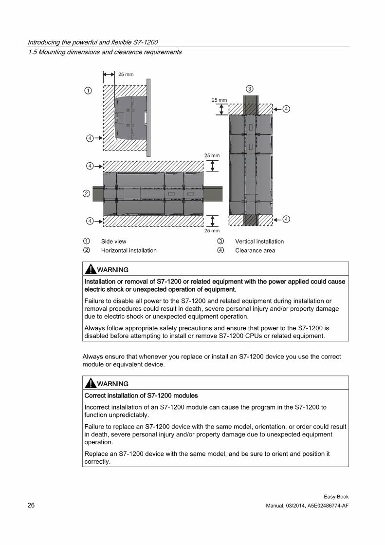
Provide adequate clearance for cooling and wiring S7-1200 devices are designed for natural convection cooling. For proper cooling, you must provide a clearance of at least 25 mm above and below the devices. Also, allow at least 25 mm of depth between the front of the modules and the inside of the enclosure.
CAUTION
For vertical mounting, the maximum allowable ambient temperature is reduced by 10 degrees C.
Orient a vertically mounted S7-1200 system as shown in the following figure.
Ensure that the S7-1200 system is mounted correctly.
When planning your layout for the S7-1200 system, allow enough clearance for the wiring and communications cable connections.
Introducing the powerful and flexible S7-1200 1.5 Mounting dimensions and clearance requirements
Easy Book 26 Manual, 03/2014, A5E02486774-AF
① Side view ③ Vertical installation ② Horizontal installation ④ Clearance area
WARNING
Installation or removal of S7-1200 or related equipment with the power applied could cause electric shock or unexpected operation of equipment.
Failure to disable all power to the S7-1200 and related equipment during installation or removal procedures could result in death, severe personal injury and/or property damage due to electric shock or unexpected equipment operation.
Always follow appropriate safety precautions and ensure that power to the S7-1200 is disabled before attempting to install or remove S7-1200 CPUs or related equipment.
Always ensure that whenever you replace or install an S7-1200 device you use the correct module or equivalent device.
WARNING
Correct installation of S7-1200 modules
Incorrect installation of an S7-1200 module can cause the program in the S7-1200 to function unpredictably.
Failure to replace an S7-1200 device with the same model, orientation, or order could result in death, severe personal injury and/or property damage due to unexpected equipment operation.
Replace an S7-1200 device with the same model, and be sure to orient and position it correctly.
Introducing the powerful and flexible S7-1200 1.6 New features
Easy Book Manual, 03/2014, A5E02486774-AF 27
1.6 New features The following features are new in this release:
● The S7-1200 supports new Organization Blocks (OBs) (Page 89) with differences in priority levels and interrupts.
● The Web server (Page 193) now supports the display of standard Web pages and user-defined Web pages from a mobile device as well as from a PC. The standard Web pages are available in English, German, French, Spanish, Italian, and Simplified Chinese with this release.
● The "Download in Run" (Page 272) feature now supports a maximum of twenty blocks that you can download in RUN mode. You can also add tags and modify tags in existing data blocks and function blocks and download the modified data blocks in RUN mode.
● The online and diagnostic tools of STEP 7 provide the means to perform a firmware update (Page 269) of your CPU, signal modules, communication modules, and attached signal or communication board.
● STEP 7 includes a trace and logic analyzer function (Page 274) that you can use with the V4.0 S7-1200 CPUs. With this feature, you can configure specific data that you want to trace and record when the CPU meets a trigger condition that you define. The CPU stores the recorded data, and STEP 7 provides tools for retrieving and analyzing the recorded data.
● New programming instructions:
– Set tag on signal edge: R_TRIG, F_TRIG
– Write local time: WR_LOC_T
– String maximum length: MAX_LEN
– Time of day interrupts: SET_TINTL, CAN_TINT, ACT_TINT, QRY_TINT
– Process recipes: RecipeExport, RecipeImport
– Address handling: LOG2GEO, RD_ADDR
– Motion control: MC_WriteParam, MC_ReadParam
– Enable / disable password: ENDIS_PW
● HSC improvements to allow any HSC instruction input or output to be assigned to any built-in or SB digital input
● PTO/PWM improvements to allow any PTO/PWM instruction input or output to be assigned to any built-in or SB digital output
● Enhanced library features, including versioning
Introducing the powerful and flexible S7-1200 1.6 New features
Easy Book 28 Manual, 03/2014, A5E02486774-AF
New modules for the S7-1200 New modules expand the power of the S7-1200 CPU and provide the flexibility to meet your automation needs:
● New CPU 1217C DC/DC/DC with high-speed differential points
● New and improved S7-1200 signal modules. The new signal modules (6ES7 2xx-xxx32-0XB0) replace existing signal modules (6ES7 2xx-xxx30-0XB0). The new modules provide:
– 4-20 mA range added to analog input and output modules
– Wirebreak detection when using 4-20 mA added to analog input modules
– Connector keying to prevent errors when plugging in field wiring connectors added to modules with relay outputs
– Spare parts compatibility: you can employ the revised module in place of existing modules without any changes.
● New spare parts available for use with S7-1200 CPUs
● New CPU 1217C Input Simulator (6ES7 274-1XK30-0XA0)
● New SM 1278 4xIO-Link Master (6ES7 278-4BD32-0XB0) functions as both a signal module and a communication module, and allows connection of up to 4 IO-Link slaves (3-wire connection) or 4 standard actuators or standard encoders
● New S7-1200 Potentiometer module (6ES7 274-1XA30-0XA0)
● New CM CANopen for S7-1200 is a plug-in module that allows you to connect CANopen devices to the S7-1200 PLC. It can be configured to be both master or slave.
Exchanging your V3.0 CPU for a V4.0 CPU If you are replacing an S7-1200 V3.0 CPU with an S7-1200 V4.0 CPU, take note of the documented differences in the versions.
See also Basic HMI panels (Page 22)
Easy Book Manual, 03/2014, A5E02486774-AF 29
STEP 7 makes the work easy 2
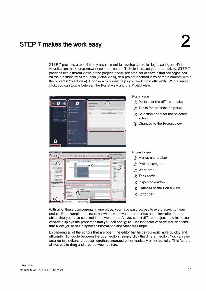
STEP 7 provides a user-friendly environment to develop controller logic, configure HMI visualization, and setup network communication. To help increase your productivity, STEP 7 provides two different views of the project: a task-oriented set of portals that are organized on the functionality of the tools (Portal view), or a project-oriented view of the elements within the project (Project view). Choose which view helps you work most efficiently. With a single click, you can toggle between the Portal view and the Project view.
Portal view ① Portals for the different tasks
② Tasks for the selected portal
③ Selection panel for the selected action
④ Changes to the Project view
Project view ① Menus and toolbar
② Project navigator
③ Work area
④ Task cards
⑤ Inspector window
⑥ Changes to the Portal view
⑦ Editor bar
With all of these components in one place, you have easy access to every aspect of your project. For example, the inspector window shows the properties and information for the object that you have selected in the work area. As you select different objects, the inspector window displays the properties that you can configure. The inspector window includes tabs that allow you to see diagnostic information and other messages.
By showing all of the editors that are open, the editor bar helps you work more quickly and efficiently. To toggle between the open editors, simply click the different editor. You can also arrange two editors to appear together, arranged either vertically or horizontally. This feature allows you to drag and drop between editors.
STEP 7 makes the work easy 2.1 Easy to insert instructions into your user program
Easy Book 30 Manual, 03/2014, A5E02486774-AF
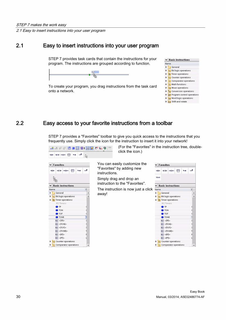
2.1 Easy to insert instructions into your user program STEP 7 provides task cards that contain the instructions for your program. The instructions are grouped according to function.
To create your program, you drag instructions from the task card onto a network.
2.2 Easy access to your favorite instructions from a toolbar STEP 7 provides a "Favorites" toolbar to give you quick access to the instructions that you frequently use. Simply click the icon for the instruction to insert it into your network!
(For the "Favorites" in the instruction tree, double-click the icon.)
You can easily customize the "Favorites" by adding new instructions. Simply drag and drop an instruction to the "Favorites". The instruction is now just a click away!
STEP 7 makes the work easy 2.3 Easy to add inputs or outputs to LAD and FBD instructions
Easy Book Manual, 03/2014, A5E02486774-AF 31
2.3 Easy to add inputs or outputs to LAD and FBD instructions
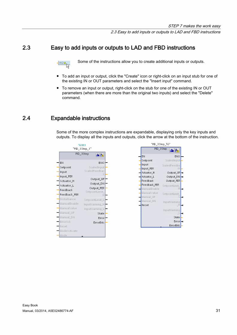
Some of the instructions allow you to create additional inputs or outputs.
● To add an input or output, click the "Create" icon or right-click on an input stub for one of the existing IN or OUT parameters and select the "Insert input" command.
● To remove an input or output, right-click on the stub for one of the existing IN or OUT parameters (when there are more than the original two inputs) and select the "Delete" command.
2.4 Expandable instructions Some of the more complex instructions are expandable, displaying only the key inputs and outputs. To display all the inputs and outputs, click the arrow at the bottom of the instruction.
STEP 7 makes the work easy 2.5 Easy to change the operating mode of the CPU
Easy Book 32 Manual, 03/2014, A5E02486774-AF
2.5 Easy to change the operating mode of the CPU The CPU does not have a physical switch for changing the operating mode (STOP or RUN).
Use the "Start CPU" and "Stop CPU" toolbar buttons to change the operating mode of the CPU.
When you configure the CPU in the device configuration, you configure the start-up behavior in the properties of the CPU (Page 76).
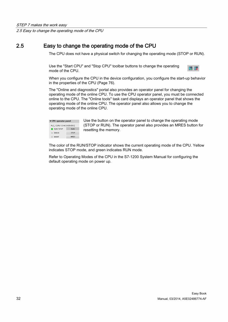
The "Online and diagnostics" portal also provides an operator panel for changing the operating mode of the online CPU. To use the CPU operator panel, you must be connected online to the CPU. The "Online tools" task card displays an operator panel that shows the operating mode of the online CPU. The operator panel also allows you to change the operating mode of the online CPU.
Use the button on the operator panel to change the operating mode (STOP or RUN). The operator panel also provides an MRES button for resetting the memory.
The color of the RUN/STOP indicator shows the current operating mode of the CPU. Yellow indicates STOP mode, and green indicates RUN mode.
Refer to Operating Modes of the CPU in the S7-1200 System Manual for configuring the default operating mode on power up.
STEP 7 makes the work easy 2.6 Easy to modify the appearance and configuration of STEP 7
Easy Book Manual, 03/2014, A5E02486774-AF 33
2.6 Easy to modify the appearance and configuration of STEP 7
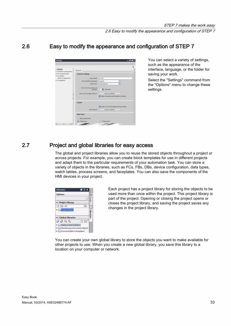
You can select a variety of settings, such as the appearance of the interface, language, or the folder for saving your work. Select the "Settings" command from the "Options" menu to change these settings.
2.7 Project and global libraries for easy access The global and project libraries allow you to reuse the stored objects throughout a project or across projects. For example, you can create block templates for use in different projects and adapt them to the particular requirements of your automation task. You can store a variety of objects in the libraries, such as FCs, FBs, DBs, device configuration, data types, watch tables, process screens, and faceplates. You can also save the components of the HMI devices in your project.
Each project has a project library for storing the objects to be used more than once within the project. This project library is part of the project. Opening or closing the project opens or closes the project library, and saving the project saves any changes in the project library.
You can create your own global library to store the objects you want to make available for other projects to use. When you create a new global library, you save this library to a location on your computer or network.
STEP 7 makes the work easy 2.8 Easy to select a version of an instruction
Easy Book 34 Manual, 03/2014, A5E02486774-AF
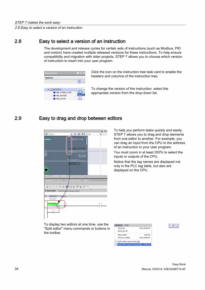
2.8 Easy to select a version of an instruction The development and release cycles for certain sets of instructions (such as Modbus, PID and motion) have created multiple released versions for these instructions. To help ensure compatibility and migration with older projects, STEP 7 allows you to choose which version of instruction to insert into your user program.
Click the icon on the instruction tree task card to enable the headers and columns of the instruction tree.
To change the version of the instruction, select the appropriate version from the drop-down list.
2.9 Easy to drag and drop between editors
To help you perform tasks quickly and easily, STEP 7 allows you to drag and drop elements from one editor to another. For example, you can drag an input from the CPU to the address of an instruction in your user program. You must zoom in at least 200% to select the inputs or outputs of the CPU. Notice that the tag names are displayed not only in the PLC tag table, but also are displayed on the CPU.
To display two editors at one time, use the "Split editor" menu commands or buttons in the toolbar.
STEP 7 makes the work easy 2.10 Changing the call type for a DB
Easy Book Manual, 03/2014, A5E02486774-AF 35
To toggle between the editors that have been opened, click the icons in the editor bar.
2.10 Changing the call type for a DB
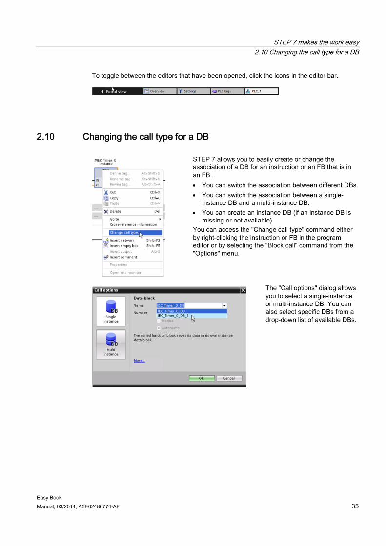
STEP 7 allows you to easily create or change the association of a DB for an instruction or an FB that is in an FB. • You can switch the association between different DBs. • You can switch the association between a single-
instance DB and a multi-instance DB. • You can create an instance DB (if an instance DB is
missing or not available). You can access the "Change call type" command either by right-clicking the instruction or FB in the program editor or by selecting the "Block call" command from the "Options" menu.
The "Call options" dialog allows you to select a single-instance or multi-instance DB. You can also select specific DBs from a drop-down list of available DBs.
STEP 7 makes the work easy 2.11 Temporarily disconnecting devices from a network
Easy Book 36 Manual, 03/2014, A5E02486774-AF
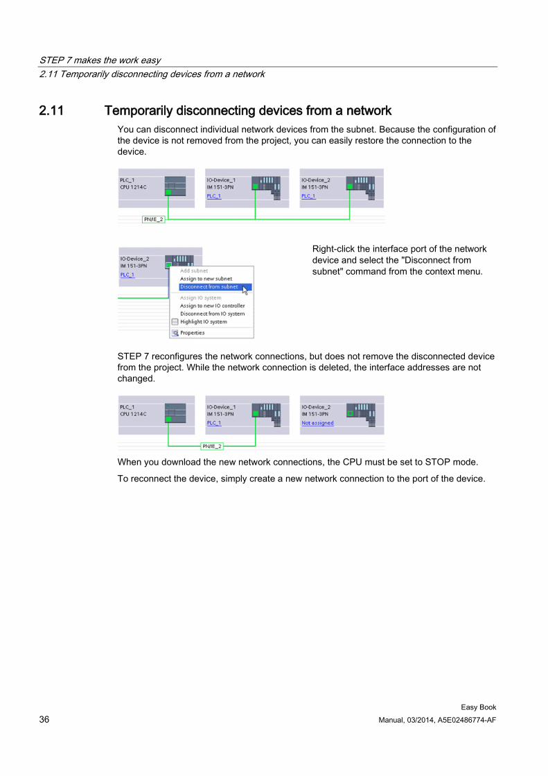
2.11 Temporarily disconnecting devices from a network You can disconnect individual network devices from the subnet. Because the configuration of the device is not removed from the project, you can easily restore the connection to the device.
Right-click the interface port of the network device and select the "Disconnect from subnet" command from the context menu.
STEP 7 reconfigures the network connections, but does not remove the disconnected device from the project. While the network connection is deleted, the interface addresses are not changed.
When you download the new network connections, the CPU must be set to STOP mode.
To reconnect the device, simply create a new network connection to the port of the device.
STEP 7 makes the work easy 2.12 Easy to virtually "unplug" modules without losing the configuration
Easy Book Manual, 03/2014, A5E02486774-AF 37
2.12 Easy to virtually "unplug" modules without losing the configuration
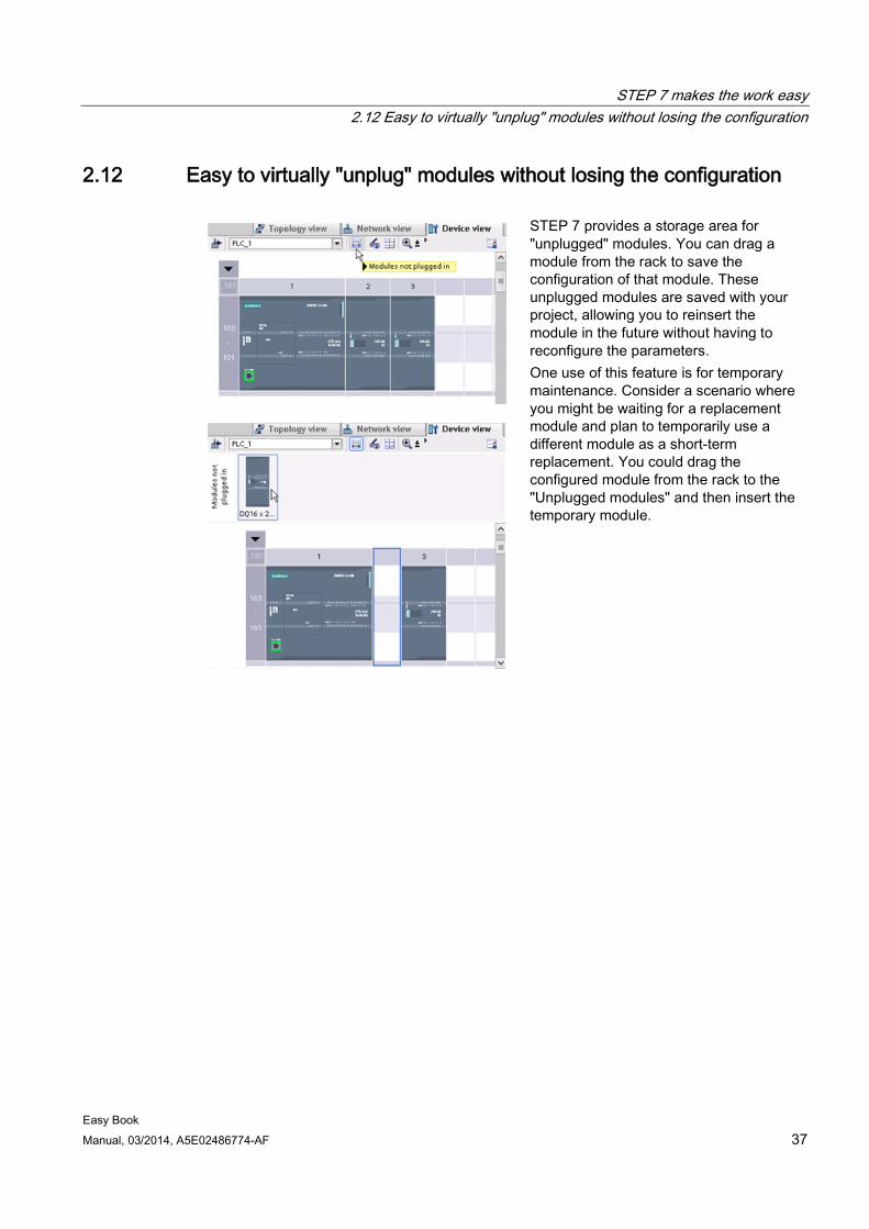
STEP 7 provides a storage area for "unplugged" modules. You can drag a module from the rack to save the configuration of that module. These unplugged modules are saved with your project, allowing you to reinsert the module in the future without having to reconfigure the parameters. One use of this feature is for temporary maintenance. Consider a scenario where you might be waiting for a replacement module and plan to temporarily use a different module as a short-term replacement. You could drag the configured module from the rack to the "Unplugged modules" and then insert the temporary module.

STEP 7 makes the work easy 2.12 Easy to virtually "unplug" modules without losing the configuration
Easy Book 38 Manual, 03/2014, A5E02486774-AF
Easy Book Manual, 03/2014, A5E02486774-AF 39
Getting started 3 3.1 Create a project
Working with STEP 7 is easy! See how quickly you can get started with creating a project.
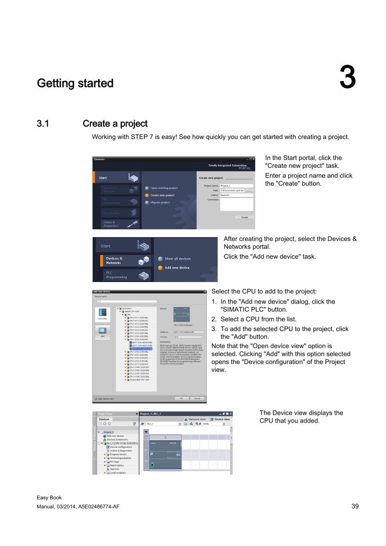
In the Start portal, click the "Create new project" task. Enter a project name and click the "Create" button.
After creating the project, select the Devices & Networks portal. Click the "Add new device" task.
Select the CPU to add to the project: 1. In the "Add new device" dialog, click the
"SIMATIC PLC" button. 2. Select a CPU from the list. 3. To add the selected CPU to the project, click
the "Add" button. Note that the "Open device view" option is selected. Clicking "Add" with this option selected opens the "Device configuration" of the Project view.
The Device view displays the CPU that you added.
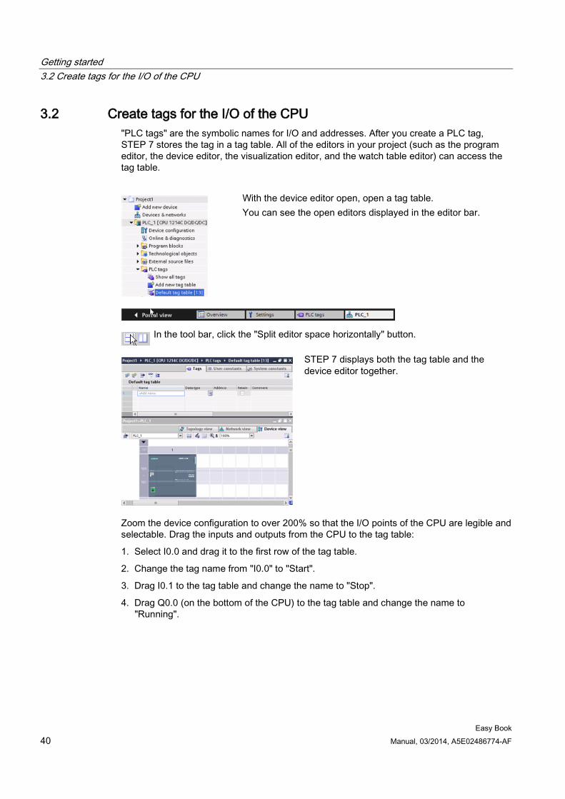
Getting started 3.2 Create tags for the I/O of the CPU
Easy Book 40 Manual, 03/2014, A5E02486774-AF
3.2 Create tags for the I/O of the CPU "PLC tags" are the symbolic names for I/O and addresses. After you create a PLC tag, STEP 7 stores the tag in a tag table. All of the editors in your project (such as the program editor, the device editor, the visualization editor, and the watch table editor) can access the tag table.
With the device editor open, open a tag table. You can see the open editors displayed in the editor bar.
In the tool bar, click the "Split editor space horizontally" button.
STEP 7 displays both the tag table and the device editor together.
Zoom the device configuration to over 200% so that the I/O points of the CPU are legible and selectable. Drag the inputs and outputs from the CPU to the tag table:
1. Select I0.0 and drag it to the first row of the tag table.
2. Change the tag name from "I0.0" to "Start".
3. Drag I0.1 to the tag table and change the name to "Stop".
4. Drag Q0.0 (on the bottom of the CPU) to the tag table and change the name to "Running".
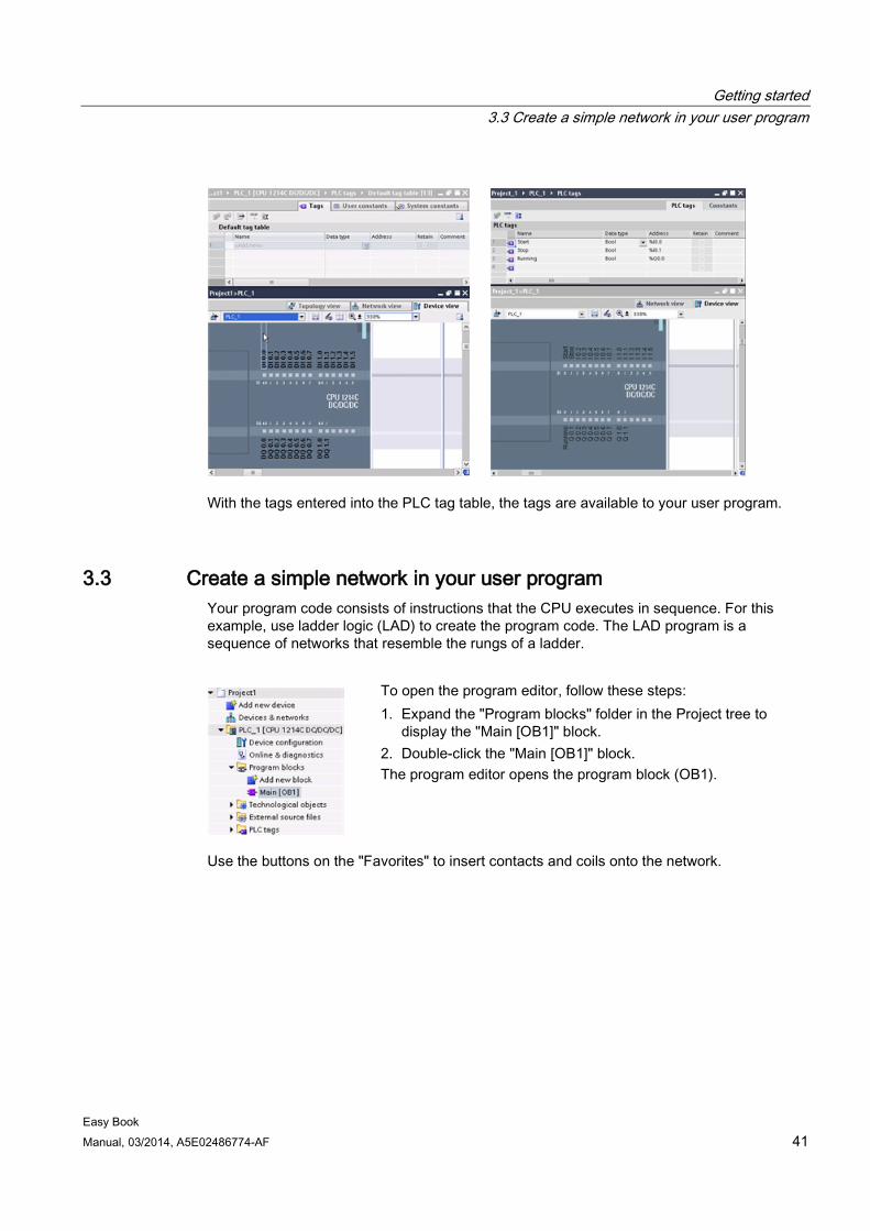
Getting started 3.3 Create a simple network in your user program
Easy Book Manual, 03/2014, A5E02486774-AF 41
With the tags entered into the PLC tag table, the tags are available to your user program.
3.3 Create a simple network in your user program Your program code consists of instructions that the CPU executes in sequence. For this example, use ladder logic (LAD) to create the program code. The LAD program is a sequence of networks that resemble the rungs of a ladder.
To open the program editor, follow these steps: 1. Expand the "Program blocks" folder in the Project tree to
display the "Main [OB1]" block. 2. Double-click the "Main [OB1]" block. The program editor opens the program block (OB1).
Use the buttons on the "Favorites" to insert contacts and coils onto the network.
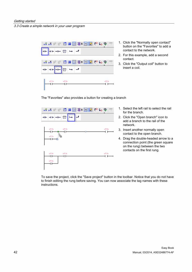
Getting started 3.3 Create a simple network in your user program
Easy Book 42 Manual, 03/2014, A5E02486774-AF
1. Click the "Normally open contact" button on the "Favorites" to add a contact to the network.
2. For this example, add a second contact.
3. Click the "Output coil" button to insert a coil.
The "Favorites" also provides a button for creating a branch
1. Select the left rail to select the rail for the branch.
2. Click the "Open branch" icon to add a branch to the rail of the network.
3. Insert another normally open contact to the open branch.
4. Drag the double-headed arrow to a connection point (the green square on the rung) between the two contacts on the first rung.
To save the project, click the "Save project" button in the toolbar. Notice that you do not have to finish editing the rung before saving. You can now associate the tag names with these instructions.
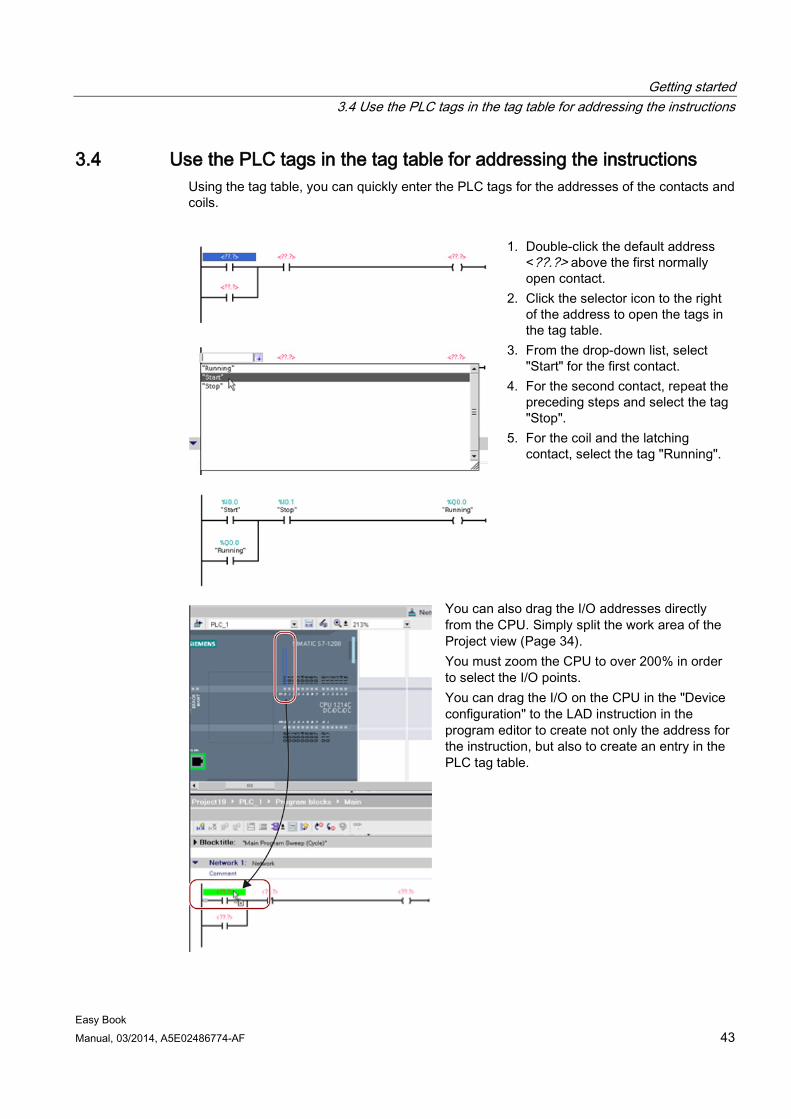
Getting started 3.4 Use the PLC tags in the tag table for addressing the instructions
Easy Book Manual, 03/2014, A5E02486774-AF 43
3.4 Use the PLC tags in the tag table for addressing the instructions Using the tag table, you can quickly enter the PLC tags for the addresses of the contacts and coils.
1. Double-click the default address <??.?> above the first normally open contact.
2. Click the selector icon to the right of the address to open the tags in the tag table.
3. From the drop-down list, select "Start" for the first contact.
4. For the second contact, repeat the preceding steps and select the tag "Stop".
5. For the coil and the latching contact, select the tag "Running".
You can also drag the I/O addresses directly from the CPU. Simply split the work area of the Project view (Page 34). You must zoom the CPU to over 200% in order to select the I/O points. You can drag the I/O on the CPU in the "Device configuration" to the LAD instruction in the program editor to create not only the address for the instruction, but also to create an entry in the PLC tag table.
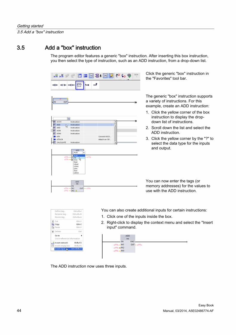
Getting started 3.5 Add a "box" instruction
Easy Book 44 Manual, 03/2014, A5E02486774-AF
3.5 Add a "box" instruction The program editor features a generic "box" instruction. After inserting this box instruction, you then select the type of instruction, such as an ADD instruction, from a drop-down list.
Click the generic "box" instruction in the "Favorites" tool bar.
The generic "box" instruction supports a variety of instructions. For this example, create an ADD instruction: 1. Click the yellow corner of the box
instruction to display the drop-down list of instructions.
2. Scroll down the list and select the ADD instruction.
3. Click the yellow corner by the "?" to select the data type for the inputs and output.
You can now enter the tags (or memory addresses) for the values to use with the ADD instruction.
You can also create additional inputs for certain instructions: 1. Click one of the inputs inside the box. 2. Right-click to display the context menu and select the "Insert
input" command.
The ADD instruction now uses three inputs.
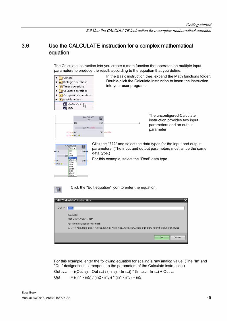
Getting started 3.6 Use the CALCULATE instruction for a complex mathematical equation
Easy Book Manual, 03/2014, A5E02486774-AF 45
3.6 Use the CALCULATE instruction for a complex mathematical equation
The Calculate instruction lets you create a math function that operates on multiple input parameters to produce the result, according to the equation that you define.
In the Basic instruction tree, expand the Math functions folder. Double-click the Calculate instruction to insert the instruction into your user program.
The unconfigured Calculate instruction provides two input parameters and an output parameter.
Click the "???" and select the data types for the input and output parameters. (The input and output parameters must all be the same data type.) For this example, select the "Real" data type.
Click the "Edit equation" icon to enter the equation.
For this example, enter the following equation for scaling a raw analog value. (The "In" and "Out" designations correspond to the parameters of the Calculate instruction.) Out value = ((Out high - Out low) / (In high - In low)) * (In value - In low) + Out low Out = ((in4 - in5) / (in2 - in3)) * (in1 - in3) + in5
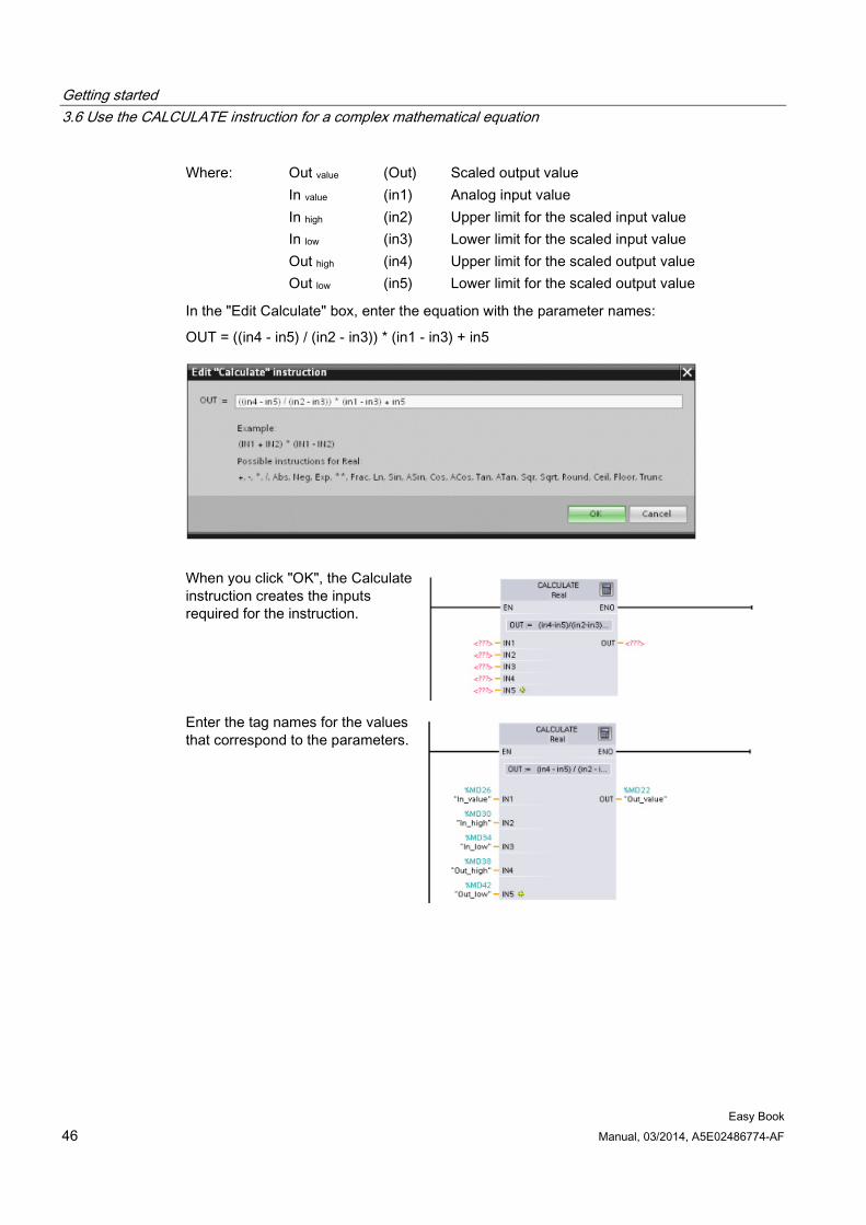
Getting started 3.6 Use the CALCULATE instruction for a complex mathematical equation
Easy Book 46 Manual, 03/2014, A5E02486774-AF
Where: Out value (Out) Scaled output value In value (in1) Analog input value In high (in2) Upper limit for the scaled input value In low (in3) Lower limit for the scaled input value Out high (in4) Upper limit for the scaled output value Out low (in5) Lower limit for the scaled output value
In the "Edit Calculate" box, enter the equation with the parameter names:
OUT = ((in4 - in5) / (in2 - in3)) * (in1 - in3) + in5
When you click "OK", the Calculate instruction creates the inputs required for the instruction.
Enter the tag names for the values that correspond to the parameters.
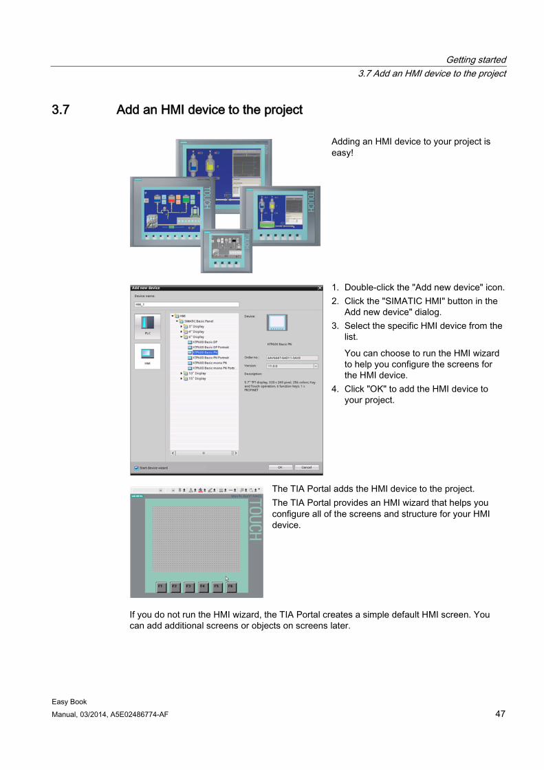
Getting started 3.7 Add an HMI device to the project
Easy Book Manual, 03/2014, A5E02486774-AF 47
3.7 Add an HMI device to the project
Adding an HMI device to your project is easy!
1. Double-click the "Add new device" icon. 2. Click the "SIMATIC HMI" button in the
Add new device" dialog. 3. Select the specific HMI device from the
list.
You can choose to run the HMI wizard to help you configure the screens for the HMI device.
4. Click "OK" to add the HMI device to your project.
The TIA Portal adds the HMI device to the project. The TIA Portal provides an HMI wizard that helps you configure all of the screens and structure for your HMI device.
If you do not run the HMI wizard, the TIA Portal creates a simple default HMI screen. You can add additional screens or objects on screens later.
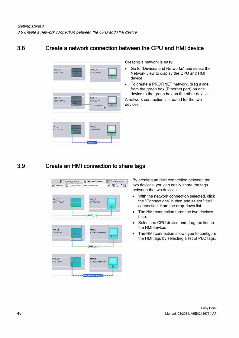
Getting started 3.8 Create a network connection between the CPU and HMI device
Easy Book 48 Manual, 03/2014, A5E02486774-AF
3.8 Create a network connection between the CPU and HMI device
Creating a network is easy! • Go to "Devices and Networks" and select the
Network view to display the CPU and HMI device.
• To create a PROFINET network, drag a line from the green box (Ethernet port) on one device to the green box on the other device.
A network connection is created for the two devices.
3.9 Create an HMI connection to share tags
By creating an HMI connection between the two devices, you can easily share the tags between the two devices. • With the network connection selected, click
the "Connections" button and select "HMI connection" from the drop-down list.
• The HMI connection turns the two devices blue.
• Select the CPU device and drag the line to the HMI device.
• The HMI connection allows you to configure the HMI tags by selecting a list of PLC tags.
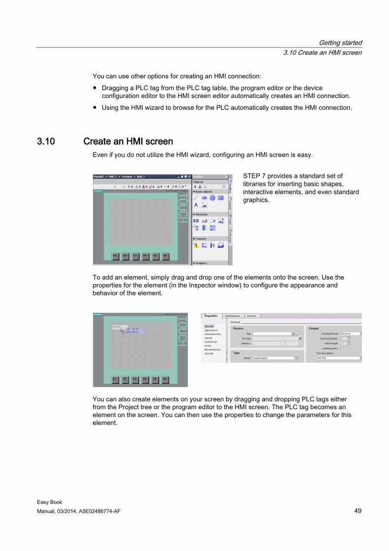
Getting started 3.10 Create an HMI screen
Easy Book Manual, 03/2014, A5E02486774-AF 49
You can use other options for creating an HMI connection:
● Dragging a PLC tag from the PLC tag table, the program editor or the device configuration editor to the HMI screen editor automatically creates an HMI connection.
● Using the HMI wizard to browse for the PLC automatically creates the HMI connection.
3.10 Create an HMI screen Even if you do not utilize the HMI wizard, configuring an HMI screen is easy.
STEP 7 provides a standard set of libraries for inserting basic shapes, interactive elements, and even standard graphics.
To add an element, simply drag and drop one of the elements onto the screen. Use the properties for the element (in the Inspector window) to configure the appearance and behavior of the element.
You can also create elements on your screen by dragging and dropping PLC tags either from the Project tree or the program editor to the HMI screen. The PLC tag becomes an element on the screen. You can then use the properties to change the parameters for this element.
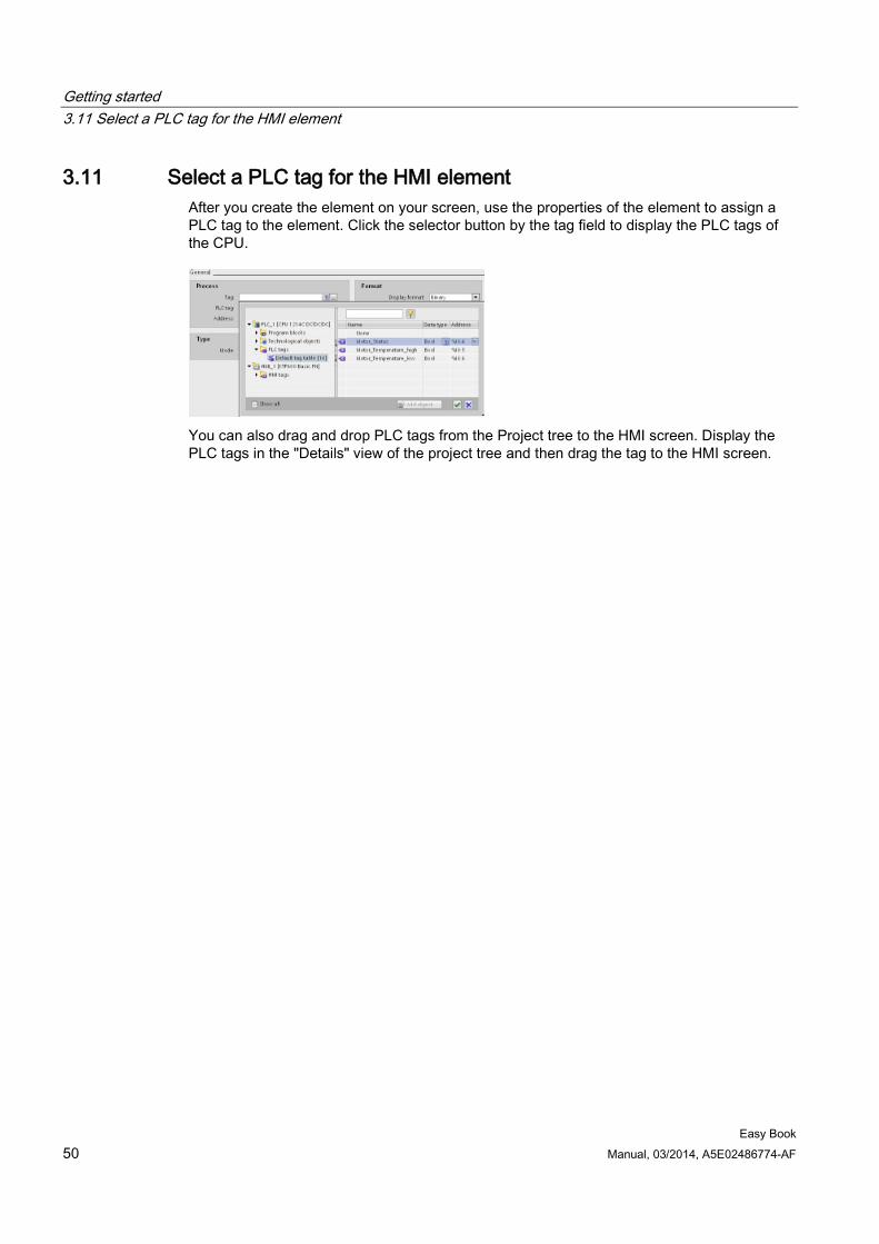
Getting started 3.11 Select a PLC tag for the HMI element
Easy Book 50 Manual, 03/2014, A5E02486774-AF
3.11 Select a PLC tag for the HMI element After you create the element on your screen, use the properties of the element to assign a PLC tag to the element. Click the selector button by the tag field to display the PLC tags of the CPU.
You can also drag and drop PLC tags from the Project tree to the HMI screen. Display the PLC tags in the "Details" view of the project tree and then drag the tag to the HMI screen.
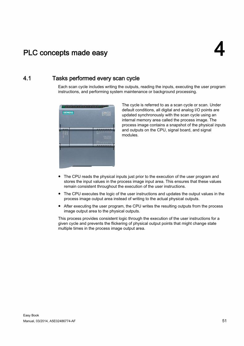
Easy Book Manual, 03/2014, A5E02486774-AF 51
PLC concepts made easy 4 4.1 Tasks performed every scan cycle
Each scan cycle includes writing the outputs, reading the inputs, executing the user program instructions, and performing system maintenance or background processing.
The cycle is referred to as a scan cycle or scan. Under default conditions, all digital and analog I/O points are updated synchronously with the scan cycle using an internal memory area called the process image. The process image contains a snapshot of the physical inputs and outputs on the CPU, signal board, and signal modules.
● The CPU reads the physical inputs just prior to the execution of the user program and stores the input values in the process image input area. This ensures that these values remain consistent throughout the execution of the user instructions.
● The CPU executes the logic of the user instructions and updates the output values in the process image output area instead of writing to the actual physical outputs.
● After executing the user program, the CPU writes the resulting outputs from the process image output area to the physical outputs.
This process provides consistent logic through the execution of the user instructions for a given cycle and prevents the flickering of physical output points that might change state multiple times in the process image output area.
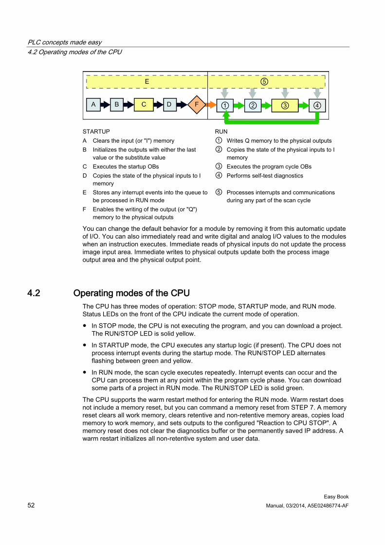
PLC concepts made easy 4.2 Operating modes of the CPU
Easy Book 52 Manual, 03/2014, A5E02486774-AF
STARTUP RUN A Clears the input (or "I") memory ① Writes Q memory to the physical outputs B Initializes the outputs with either the last
value or the substitute value ② Copies the state of the physical inputs to I
memory C Executes the startup OBs ③ Executes the program cycle OBs D Copies the state of the physical inputs to I
memory ④ Performs self-test diagnostics
E Stores any interrupt events into the queue to be processed in RUN mode
⑤ Processes interrupts and communications during any part of the scan cycle
F Enables the writing of the output (or "Q") memory to the physical outputs
You can change the default behavior for a module by removing it from this automatic update of I/O. You can also immediately read and write digital and analog I/O values to the modules when an instruction executes. Immediate reads of physical inputs do not update the process image input area. Immediate writes to physical outputs update both the process image output area and the physical output point.
4.2 Operating modes of the CPU The CPU has three modes of operation: STOP mode, STARTUP mode, and RUN mode. Status LEDs on the front of the CPU indicate the current mode of operation.
● In STOP mode, the CPU is not executing the program, and you can download a project. The RUN/STOP LED is solid yellow.
● In STARTUP mode, the CPU executes any startup logic (if present). The CPU does not process interrupt events during the startup mode. The RUN/STOP LED alternates flashing between green and yellow.
● In RUN mode, the scan cycle executes repeatedly. Interrupt events can occur and the CPU can process them at any point within the program cycle phase. You can download some parts of a project in RUN mode. The RUN/STOP LED is solid green.
The CPU supports the warm restart method for entering the RUN mode. Warm restart does not include a memory reset, but you can command a memory reset from STEP 7. A memory reset clears all work memory, clears retentive and non-retentive memory areas, copies load memory to work memory, and sets outputs to the configured "Reaction to CPU STOP". A memory reset does not clear the diagnostics buffer or the permanently saved IP address. A warm restart initializes all non-retentive system and user data.
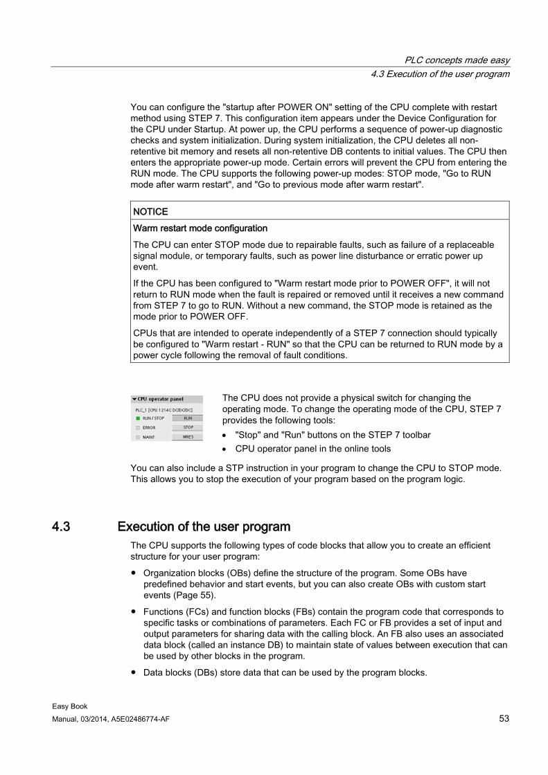
PLC concepts made easy 4.3 Execution of the user program
Easy Book Manual, 03/2014, A5E02486774-AF 53
You can configure the "startup after POWER ON" setting of the CPU complete with restart method using STEP 7. This configuration item appears under the Device Configuration for the CPU under Startup. At power up, the CPU performs a sequence of power-up diagnostic checks and system initialization. During system initialization, the CPU deletes all non-retentive bit memory and resets all non-retentive DB contents to initial values. The CPU then enters the appropriate power-up mode. Certain errors will prevent the CPU from entering the RUN mode. The CPU supports the following power-up modes: STOP mode, "Go to RUN mode after warm restart", and "Go to previous mode after warm restart".
NOTICE
Warm restart mode configuration
The CPU can enter STOP mode due to repairable faults, such as failure of a replaceable signal module, or temporary faults, such as power line disturbance or erratic power up event.
If the CPU has been configured to "Warm restart mode prior to POWER OFF", it will not return to RUN mode when the fault is repaired or removed until it receives a new command from STEP 7 to go to RUN. Without a new command, the STOP mode is retained as the mode prior to POWER OFF.
CPUs that are intended to operate independently of a STEP 7 connection should typically be configured to "Warm restart - RUN" so that the CPU can be returned to RUN mode by a power cycle following the removal of fault conditions.
The CPU does not provide a physical switch for changing the operating mode. To change the operating mode of the CPU, STEP 7 provides the following tools: • "Stop" and "Run" buttons on the STEP 7 toolbar • CPU operator panel in the online tools
You can also include a STP instruction in your program to change the CPU to STOP mode. This allows you to stop the execution of your program based on the program logic.
4.3 Execution of the user program The CPU supports the following types of code blocks that allow you to create an efficient structure for your user program:
● Organization blocks (OBs) define the structure of the program. Some OBs have predefined behavior and start events, but you can also create OBs with custom start events (Page 55).
● Functions (FCs) and function blocks (FBs) contain the program code that corresponds to specific tasks or combinations of parameters. Each FC or FB provides a set of input and output parameters for sharing data with the calling block. An FB also uses an associated data block (called an instance DB) to maintain state of values between execution that can be used by other blocks in the program.
● Data blocks (DBs) store data that can be used by the program blocks.
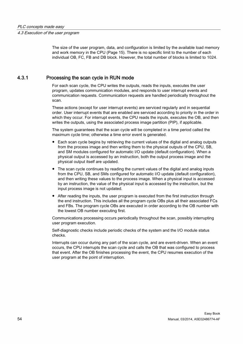
PLC concepts made easy 4.3 Execution of the user program
Easy Book 54 Manual, 03/2014, A5E02486774-AF
The size of the user program, data, and configuration is limited by the available load memory and work memory in the CPU (Page 15). There is no specific limit to the number of each individual OB, FC, FB and DB block. However, the total number of blocks is limited to 1024.
4.3.1 Processing the scan cycle in RUN mode For each scan cycle, the CPU writes the outputs, reads the inputs, executes the user program, updates communication modules, and responds to user interrupt events and communication requests. Communication requests are handled periodically throughout the scan.
These actions (except for user interrupt events) are serviced regularly and in sequential order. User interrupt events that are enabled are serviced according to priority in the order in which they occur. For interrupt events, the CPU reads the inputs, executes the OB, and then writes the outputs, using the associated process image partition (PIP), if applicable.
The system guarantees that the scan cycle will be completed in a time period called the maximum cycle time; otherwise a time error event is generated.
● Each scan cycle begins by retrieving the current values of the digital and analog outputs from the process image and then writing them to the physical outputs of the CPU, SB, and SM modules configured for automatic I/O update (default configuration). When a physical output is accessed by an instruction, both the output process image and the physical output itself are updated.
● The scan cycle continues by reading the current values of the digital and analog inputs from the CPU, SB, and SMs configured for automatic I/O update (default configuration), and then writing these values to the process image. When a physical input is accessed by an instruction, the value of the physical input is accessed by the instruction, but the input process image is not updated.
● After reading the inputs, the user program is executed from the first instruction through the end instruction. This includes all the program cycle OBs plus all their associated FCs and FBs. The program cycle OBs are executed in order according to the OB number with the lowest OB number executing first.
Communications processing occurs periodically throughout the scan, possibly interrupting user program execution.
Self-diagnostic checks include periodic checks of the system and the I/O module status checks.
Interrupts can occur during any part of the scan cycle, and are event-driven. When an event occurs, the CPU interrupts the scan cycle and calls the OB that was configured to process that event. After the OB finishes processing the event, the CPU resumes execution of the user program at the point of interruption.
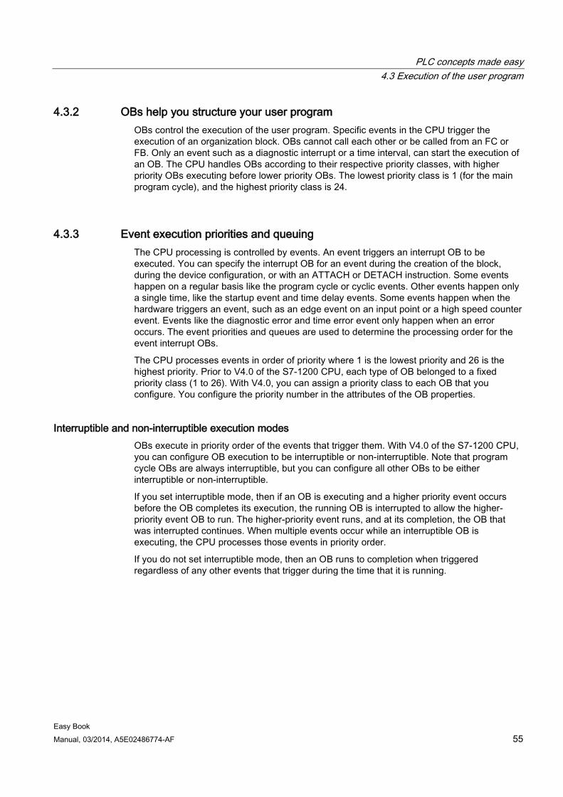
PLC concepts made easy 4.3 Execution of the user program
Easy Book Manual, 03/2014, A5E02486774-AF 55
4.3.2 OBs help you structure your user program OBs control the execution of the user program. Specific events in the CPU trigger the execution of an organization block. OBs cannot call each other or be called from an FC or FB. Only an event such as a diagnostic interrupt or a time interval, can start the execution of an OB. The CPU handles OBs according to their respective priority classes, with higher priority OBs executing before lower priority OBs. The lowest priority class is 1 (for the main program cycle), and the highest priority class is 24.
4.3.3 Event execution priorities and queuing The CPU processing is controlled by events. An event triggers an interrupt OB to be executed. You can specify the interrupt OB for an event during the creation of the block, during the device configuration, or with an ATTACH or DETACH instruction. Some events happen on a regular basis like the program cycle or cyclic events. Other events happen only a single time, like the startup event and time delay events. Some events happen when the hardware triggers an event, such as an edge event on an input point or a high speed counter event. Events like the diagnostic error and time error event only happen when an error occurs. The event priorities and queues are used to determine the processing order for the event interrupt OBs.
The CPU processes events in order of priority where 1 is the lowest priority and 26 is the highest priority. Prior to V4.0 of the S7-1200 CPU, each type of OB belonged to a fixed priority class (1 to 26). With V4.0, you can assign a priority class to each OB that you configure. You configure the priority number in the attributes of the OB properties.
Interruptible and non-interruptible execution modes OBs execute in priority order of the events that trigger them. With V4.0 of the S7-1200 CPU, you can configure OB execution to be interruptible or non-interruptible. Note that program cycle OBs are always interruptible, but you can configure all other OBs to be either interruptible or non-interruptible.
If you set interruptible mode, then if an OB is executing and a higher priority event occurs before the OB completes its execution, the running OB is interrupted to allow the higher-priority event OB to run. The higher-priority event runs, and at its completion, the OB that was interrupted continues. When multiple events occur while an interruptible OB is executing, the CPU processes those events in priority order.
If you do not set interruptible mode, then an OB runs to completion when triggered regardless of any other events that trigger during the time that it is running.
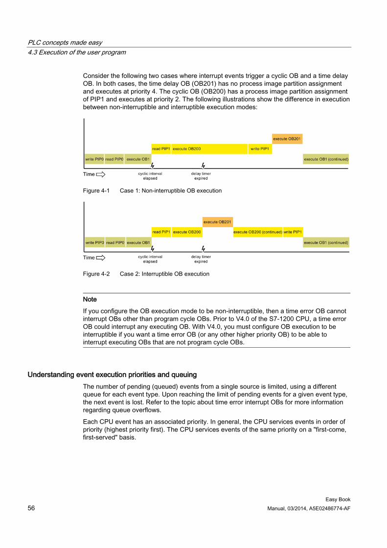
PLC concepts made easy 4.3 Execution of the user program
Easy Book 56 Manual, 03/2014, A5E02486774-AF
Consider the following two cases where interrupt events trigger a cyclic OB and a time delay OB. In both cases, the time delay OB (OB201) has no process image partition assignment and executes at priority 4. The cyclic OB (OB200) has a process image partition assignment of PIP1 and executes at priority 2. The following illustrations show the difference in execution between non-interruptible and interruptible execution modes:
Figure 4-1 Case 1: Non-interruptible OB execution
Figure 4-2 Case 2: Interruptible OB execution
Note
If you configure the OB execution mode to be non-interruptible, then a time error OB cannot interrupt OBs other than program cycle OBs. Prior to V4.0 of the S7-1200 CPU, a time error OB could interrupt any executing OB. With V4.0, you must configure OB execution to be interruptible if you want a time error OB (or any other higher priority OB) to be able to interrupt executing OBs that are not program cycle OBs.
Understanding event execution priorities and queuing The number of pending (queued) events from a single source is limited, using a different queue for each event type. Upon reaching the limit of pending events for a given event type, the next event is lost. Refer to the topic about time error interrupt OBs for more information regarding queue overflows.
Each CPU event has an associated priority. In general, the CPU services events in order of priority (highest priority first). The CPU services events of the same priority on a "first-come, first-served" basis.
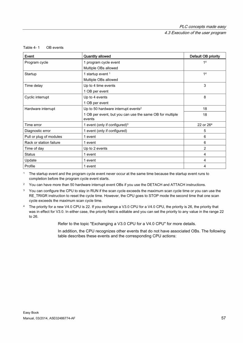
PLC concepts made easy 4.3 Execution of the user program
Easy Book Manual, 03/2014, A5E02486774-AF 57
Table 4- 1 OB events
Event Quantity allowed Default OB priority Program cycle 1 program cycle event
Multiple OBs allowed 14
Startup 1 startup event 1 Multiple OBs allowed
14
Time delay Up to 4 time events 1 OB per event
3
Cyclic interrupt Up to 4 events 1 OB per event
8
Hardware interrupt Up to 50 hardware interrupt events2 1 OB per event, but you can use the same OB for multiple events
18 18
Time error 1 event (only if configured)3 22 or 264 Diagnostic error 1 event (only if configured) 5 Pull or plug of modules 1 event 6 Rack or station failure 1 event 6 Time of day Up to 2 events 2 Status 1 event 4 Update 1 event 4 Profile 1 event 4 1 The startup event and the program cycle event never occur at the same time because the startup event runs to
completion before the program cycle event starts. 2 You can have more than 50 hardware interrupt event OBs if you use the DETACH and ATTACH instructions. 3 You can configure the CPU to stay in RUN if the scan cycle exceeds the maximum scan cycle time or you can use the
RE_TRIGR instruction to reset the cycle time. However, the CPU goes to STOP mode the second time that one scan cycle exceeds the maximum scan cycle time.
4 The priority for a new V4.0 CPU is 22. If you exchange a V3.0 CPU for a V4.0 CPU, the priority is 26, the priority that was in effect for V3.0. In either case, the priority field is editable and you can set the priority to any value in the range 22 to 26.
Refer to the topic "Exchanging a V3.0 CPU for a V4.0 CPU" for more details.
In addition, the CPU recognizes other events that do not have associated OBs. The following table describes these events and the corresponding CPU actions:
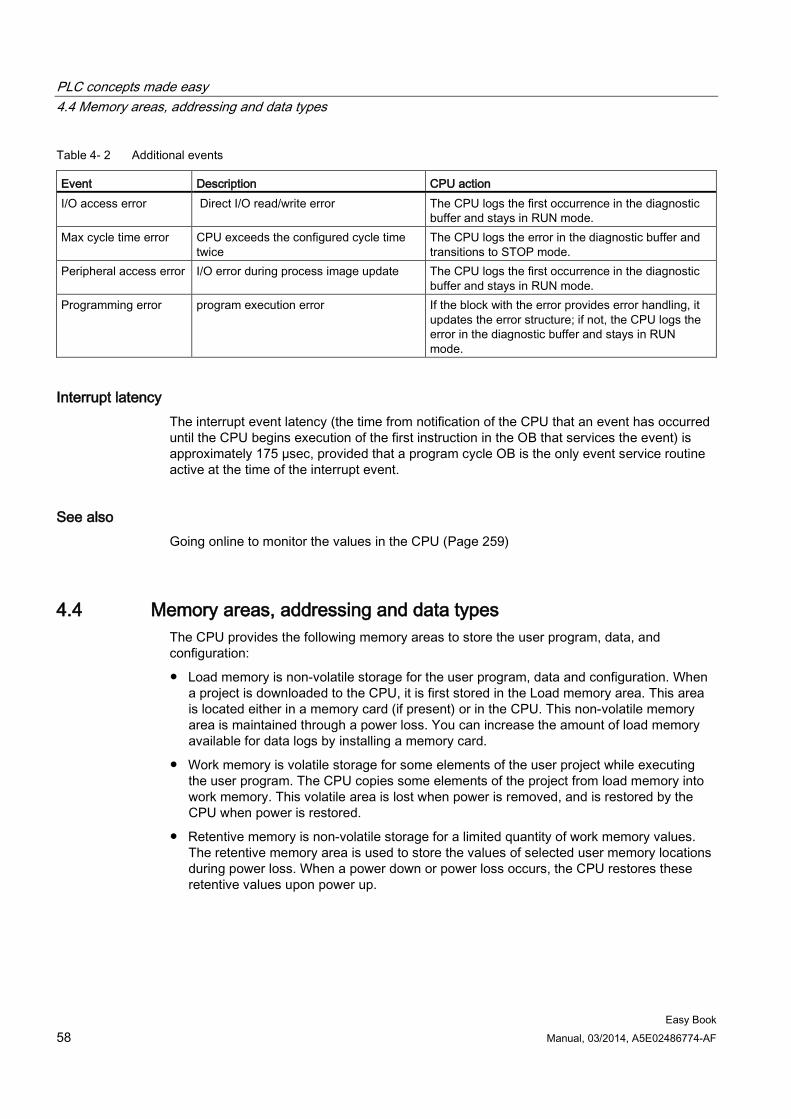
PLC concepts made easy 4.4 Memory areas, addressing and data types
Easy Book 58 Manual, 03/2014, A5E02486774-AF
Table 4- 2 Additional events
Event Description CPU action I/O access error Direct I/O read/write error The CPU logs the first occurrence in the diagnostic
buffer and stays in RUN mode. Max cycle time error CPU exceeds the configured cycle time
twice The CPU logs the error in the diagnostic buffer and transitions to STOP mode.
Peripheral access error I/O error during process image update The CPU logs the first occurrence in the diagnostic buffer and stays in RUN mode.
Programming error program execution error If the block with the error provides error handling, it updates the error structure; if not, the CPU logs the error in the diagnostic buffer and stays in RUN mode.
Interrupt latency The interrupt event latency (the time from notification of the CPU that an event has occurred until the CPU begins execution of the first instruction in the OB that services the event) is approximately 175 µsec, provided that a program cycle OB is the only event service routine active at the time of the interrupt event.
See also Going online to monitor the values in the CPU (Page 259)
4.4 Memory areas, addressing and data types The CPU provides the following memory areas to store the user program, data, and configuration:
● Load memory is non-volatile storage for the user program, data and configuration. When a project is downloaded to the CPU, it is first stored in the Load memory area. This area is located either in a memory card (if present) or in the CPU. This non-volatile memory area is maintained through a power loss. You can increase the amount of load memory available for data logs by installing a memory card.
● Work memory is volatile storage for some elements of the user project while executing the user program. The CPU copies some elements of the project from load memory into work memory. This volatile area is lost when power is removed, and is restored by the CPU when power is restored.
● Retentive memory is non-volatile storage for a limited quantity of work memory values. The retentive memory area is used to store the values of selected user memory locations during power loss. When a power down or power loss occurs, the CPU restores these retentive values upon power up.
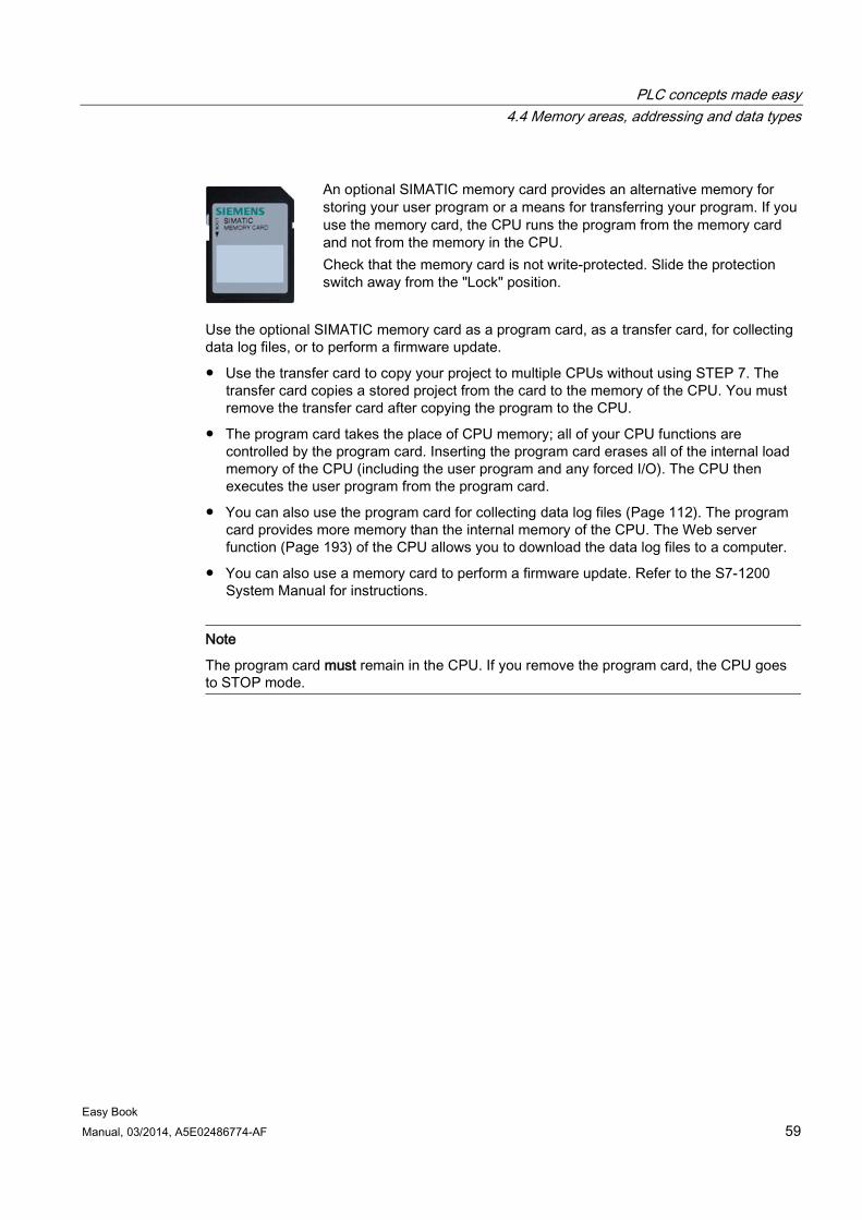
PLC concepts made easy 4.4 Memory areas, addressing and data types
Easy Book Manual, 03/2014, A5E02486774-AF 59
An optional SIMATIC memory card provides an alternative memory for storing your user program or a means for transferring your program. If you use the memory card, the CPU runs the program from the memory card and not from the memory in the CPU. Check that the memory card is not write-protected. Slide the protection switch away from the "Lock" position.
Use the optional SIMATIC memory card as a program card, as a transfer card, for collecting data log files, or to perform a firmware update.
● Use the transfer card to copy your project to multiple CPUs without using STEP 7. The transfer card copies a stored project from the card to the memory of the CPU. You must remove the transfer card after copying the program to the CPU.
● The program card takes the place of CPU memory; all of your CPU functions are controlled by the program card. Inserting the program card erases all of the internal load memory of the CPU (including the user program and any forced I/O). The CPU then executes the user program from the program card.
● You can also use the program card for collecting data log files (Page 112). The program card provides more memory than the internal memory of the CPU. The Web server function (Page 193) of the CPU allows you to download the data log files to a computer.
● You can also use a memory card to perform a firmware update. Refer to the S7-1200 System Manual for instructions.
Note
The program card must remain in the CPU. If you remove the program card, the CPU goes to STOP mode.
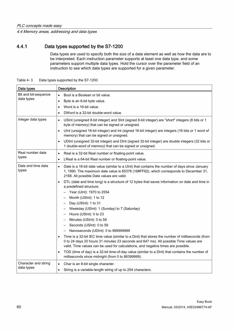
PLC concepts made easy 4.4 Memory areas, addressing and data types
Easy Book 60 Manual, 03/2014, A5E02486774-AF
4.4.1 Data types supported by the S7-1200 Data types are used to specify both the size of a data element as well as how the data are to be interpreted. Each instruction parameter supports at least one data type, and some parameters support multiple data types. Hold the cursor over the parameter field of an instruction to see which data types are supported for a given parameter.
Table 4- 3 Data types supported by the S7-1200
Data types Description Bit and bit-sequence data types
• Bool is a Boolean or bit value. • Byte is an 8-bit byte value. • Word is a 16-bit value. • DWord is a 32-bit double-word value.
Integer data types • USInt (unsigned 8-bit integer) and SInt (signed 8-bit integer) are "short" integers (8 bits or 1 byte of memory) that can be signed or unsigned.
• UInt (unsigned 16-bit integer) and Int (signed 16-bit integer) are integers (16 bits or 1 word of memory) that can be signed or unsigned.
• UDInt (unsigned 32-bit integer) and DInt (signed 32-bit integer) are double integers (32 bits or 1 double-word of memory) that can be signed or unsigned.
Real number data types
• Real is a 32-bit Real number or floating-point value. • LReal is a 64-bit Real number or floating-point value.
Date and time data types
• Date is a 16-bit date value (similar to a UInt) that contains the number of days since January 1, 1990. The maximum date value is 65378 (16#FF62), which corresponds to December 31, 2168. All possible Date values are valid.
• DTL (date and time long) is a structure of 12 bytes that saves information on date and time in a predefined structure. – Year (UInt): 1970 to 2554 – Month (USInt): 1 to 12 – Day (USInt): 1 to 31 – Weekday (USInt): 1 (Sunday) to 7 (Saturday) – Hours (USInt): 0 to 23 – Minutes (USInt): 0 to 59 – Seconds (USInt): 0 to 59 – Nanoseconds (UDInt): 0 to 999999999
• Time is a 32-bit IEC time value (similar to a Dint) that stores the number of milliseconds (from 0 to 24 days 20 hours 31 minutes 23 seconds and 647 ms). All possible Time values are valid. Time values can be used for calculations, and negative times are possible.
• TOD (time of day) is a 32-bit time-of-day value (similar to a Dint) that contains the number of milliseconds since midnight (from 0 to 86399999).
Character and string data types
• Char is an 8-bit single character. • String is a variable-length string of up to 254 characters.
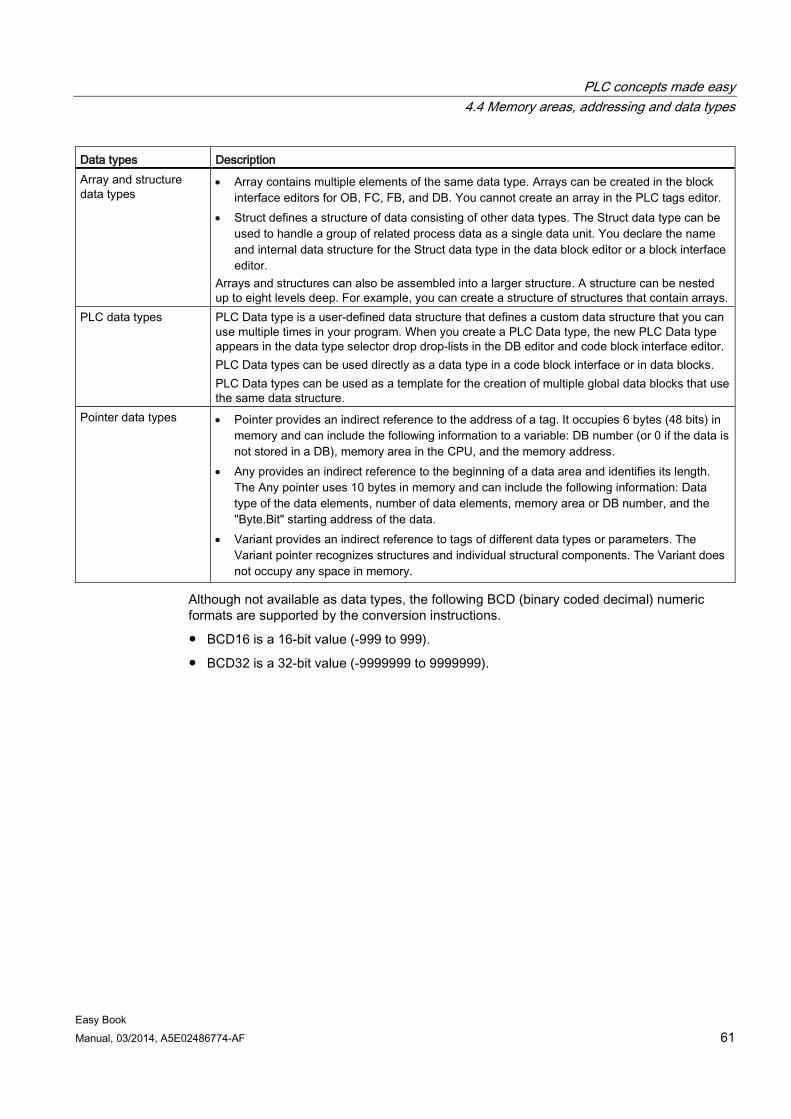
PLC concepts made easy 4.4 Memory areas, addressing and data types
Easy Book Manual, 03/2014, A5E02486774-AF 61
Data types Description Array and structure data types
• Array contains multiple elements of the same data type. Arrays can be created in the block interface editors for OB, FC, FB, and DB. You cannot create an array in the PLC tags editor.
• Struct defines a structure of data consisting of other data types. The Struct data type can be used to handle a group of related process data as a single data unit. You declare the name and internal data structure for the Struct data type in the data block editor or a block interface editor.
Arrays and structures can also be assembled into a larger structure. A structure can be nested up to eight levels deep. For example, you can create a structure of structures that contain arrays.
PLC data types PLC Data type is a user-defined data structure that defines a custom data structure that you can use multiple times in your program. When you create a PLC Data type, the new PLC Data type appears in the data type selector drop drop-lists in the DB editor and code block interface editor. PLC Data types can be used directly as a data type in a code block interface or in data blocks. PLC Data types can be used as a template for the creation of multiple global data blocks that use the same data structure.
Pointer data types • Pointer provides an indirect reference to the address of a tag. It occupies 6 bytes (48 bits) in memory and can include the following information to a variable: DB number (or 0 if the data is not stored in a DB), memory area in the CPU, and the memory address.
• Any provides an indirect reference to the beginning of a data area and identifies its length. The Any pointer uses 10 bytes in memory and can include the following information: Data type of the data elements, number of data elements, memory area or DB number, and the "Byte.Bit" starting address of the data.
• Variant provides an indirect reference to tags of different data types or parameters. The Variant pointer recognizes structures and individual structural components. The Variant does not occupy any space in memory.
Although not available as data types, the following BCD (binary coded decimal) numeric formats are supported by the conversion instructions.
● BCD16 is a 16-bit value (-999 to 999).
● BCD32 is a 32-bit value (-9999999 to 9999999).
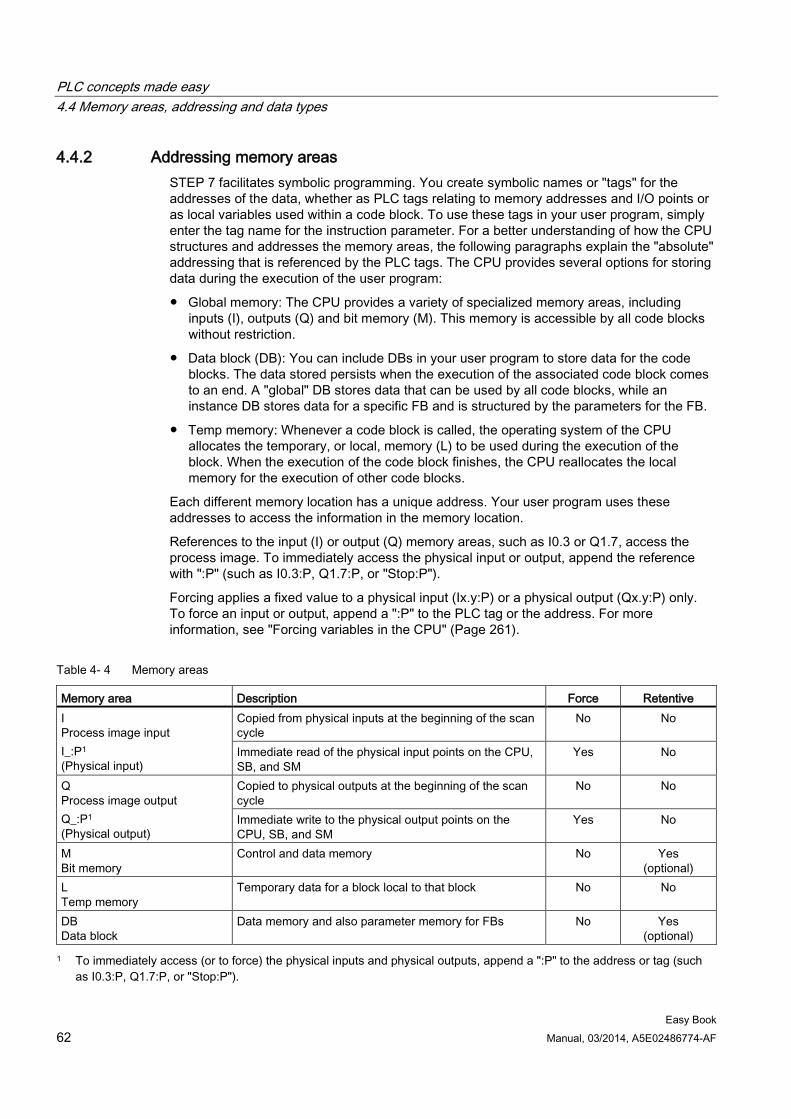
PLC concepts made easy 4.4 Memory areas, addressing and data types
Easy Book 62 Manual, 03/2014, A5E02486774-AF
4.4.2 Addressing memory areas STEP 7 facilitates symbolic programming. You create symbolic names or "tags" for the addresses of the data, whether as PLC tags relating to memory addresses and I/O points or as local variables used within a code block. To use these tags in your user program, simply enter the tag name for the instruction parameter. For a better understanding of how the CPU structures and addresses the memory areas, the following paragraphs explain the "absolute" addressing that is referenced by the PLC tags. The CPU provides several options for storing data during the execution of the user program:
● Global memory: The CPU provides a variety of specialized memory areas, including inputs (I), outputs (Q) and bit memory (M). This memory is accessible by all code blocks without restriction.
● Data block (DB): You can include DBs in your user program to store data for the code blocks. The data stored persists when the execution of the associated code block comes to an end. A "global" DB stores data that can be used by all code blocks, while an instance DB stores data for a specific FB and is structured by the parameters for the FB.
● Temp memory: Whenever a code block is called, the operating system of the CPU allocates the temporary, or local, memory (L) to be used during the execution of the block. When the execution of the code block finishes, the CPU reallocates the local memory for the execution of other code blocks.
Each different memory location has a unique address. Your user program uses these addresses to access the information in the memory location.
References to the input (I) or output (Q) memory areas, such as I0.3 or Q1.7, access the process image. To immediately access the physical input or output, append the reference with ":P" (such as I0.3:P, Q1.7:P, or "Stop:P").
Forcing applies a fixed value to a physical input (Ix.y:P) or a physical output (Qx.y:P) only. To force an input or output, append a ":P" to the PLC tag or the address. For more information, see "Forcing variables in the CPU" (Page 261).
Table 4- 4 Memory areas
Memory area Description Force Retentive I Process image input I_:P1 (Physical input)
Copied from physical inputs at the beginning of the scan cycle
No No
Immediate read of the physical input points on the CPU, SB, and SM
Yes No
Q Process image output Q_:P1 (Physical output)
Copied to physical outputs at the beginning of the scan cycle
No No
Immediate write to the physical output points on the CPU, SB, and SM
Yes No
M Bit memory
Control and data memory No Yes (optional)
L Temp memory
Temporary data for a block local to that block No No
DB Data block
Data memory and also parameter memory for FBs No Yes (optional)
1 To immediately access (or to force) the physical inputs and physical outputs, append a ":P" to the address or tag (such as I0.3:P, Q1.7:P, or "Stop:P").

PLC concepts made easy 4.4 Memory areas, addressing and data types
Easy Book Manual, 03/2014, A5E02486774-AF 63
Each different memory location has a unique address. Your user program uses these addresses to access the information in the memory location. The absolute address consists of the following elements:
● Memory area (such as I, Q, or M)
● Size of the data to be accessed (such as "B" for Byte or "W" for Word)
● Address of the data (such as Byte 3 or Word 3)
When accessing a bit in the address for a Boolean value, you do not enter a mnemonic for the size. You enter only the memory area, the byte location, and the bit location for the data (such as I0.0, Q0.1, or M3.4).
Absolute address of a memory area: A Memory area identifier B Byte address: byte 3 C Separator ("byte.bit") D Bit location of the byte (bit 4 of 8) E Bytes of the memory area F Bits of the selected byte
In the example, the memory area and byte address (M = bit memory area, and 3 = Byte 3) are followed by a period (".") to separate the bit address (bit 4).
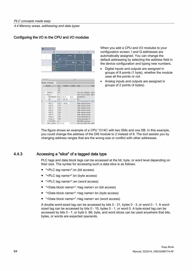
PLC concepts made easy 4.4 Memory areas, addressing and data types
Easy Book 64 Manual, 03/2014, A5E02486774-AF
Configuring the I/O in the CPU and I/O modules
When you add a CPU and I/O modules to your configuration screen, I and Q addresses are automatically assigned. You can change the default addressing by selecting the address field in the device configuration and typing new numbers. • Digital inputs and outputs are assigned in
groups of 8 points (1 byte), whether the module uses all the points or not.
• Analog inputs and outputs are assigned in groups of 2 points (4 bytes).
The figure shows an example of a CPU 1214C with two SMs and one SB. In this example, you could change the address of the DI8 module to 2 instead of 8. The tool assists you by changing address ranges that are the wrong size or conflict with other addresses.
4.4.3 Accessing a "slice" of a tagged data type PLC tags and data block tags can be accessed at the bit, byte, or word level depending on their size. The syntax for accessing such a data slice is as follows:
● "<PLC tag name>".xn (bit access)
● "<PLC tag name>".bn (byte access)
● "<PLC tag name>".wn (word access)
● "<Data block name>".<tag name>.xn (bit access)
● "<Data block name>".<tag name>.bn (byte access)
● "<Data block name>".<tag name>.wn (word access)
A double word-sized tag can be accessed by bits 0 - 31, bytes 0 - 3, or word 0 - 1. A word-sized tag can be accessed by bits 0 - 15, bytes 0 - 1, or word 0. A byte-sized tag can be accessed by bits 0 - 7, or byte 0. Bit, byte, and word slices can be used anywhere that bits, bytes, or words are expected operands.
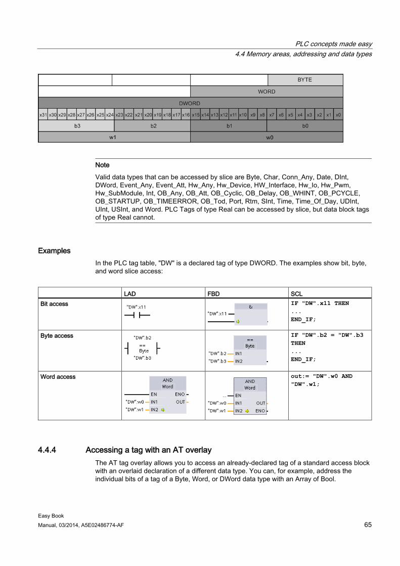
PLC concepts made easy 4.4 Memory areas, addressing and data types
Easy Book Manual, 03/2014, A5E02486774-AF 65
Note
Valid data types that can be accessed by slice are Byte, Char, Conn_Any, Date, DInt, DWord, Event_Any, Event_Att, Hw_Any, Hw_Device, HW_Interface, Hw_Io, Hw_Pwm, Hw_SubModule, Int, OB_Any, OB_Att, OB_Cyclic, OB_Delay, OB_WHINT, OB_PCYCLE, OB_STARTUP, OB_TIMEERROR, OB_Tod, Port, Rtm, SInt, Time, Time_Of_Day, UDInt, UInt, USInt, and Word. PLC Tags of type Real can be accessed by slice, but data block tags of type Real cannot.
Examples In the PLC tag table, "DW" is a declared tag of type DWORD. The examples show bit, byte, and word slice access:
LAD FBD SCL Bit access
IF "DW".x11 THEN ... END_IF;
Byte access
IF "DW".b2 = "DW".b3 THEN ... END_IF;
Word access
out:= "DW".w0 AND "DW".w1;
4.4.4 Accessing a tag with an AT overlay The AT tag overlay allows you to access an already-declared tag of a standard access block with an overlaid declaration of a different data type. You can, for example, address the individual bits of a tag of a Byte, Word, or DWord data type with an Array of Bool.
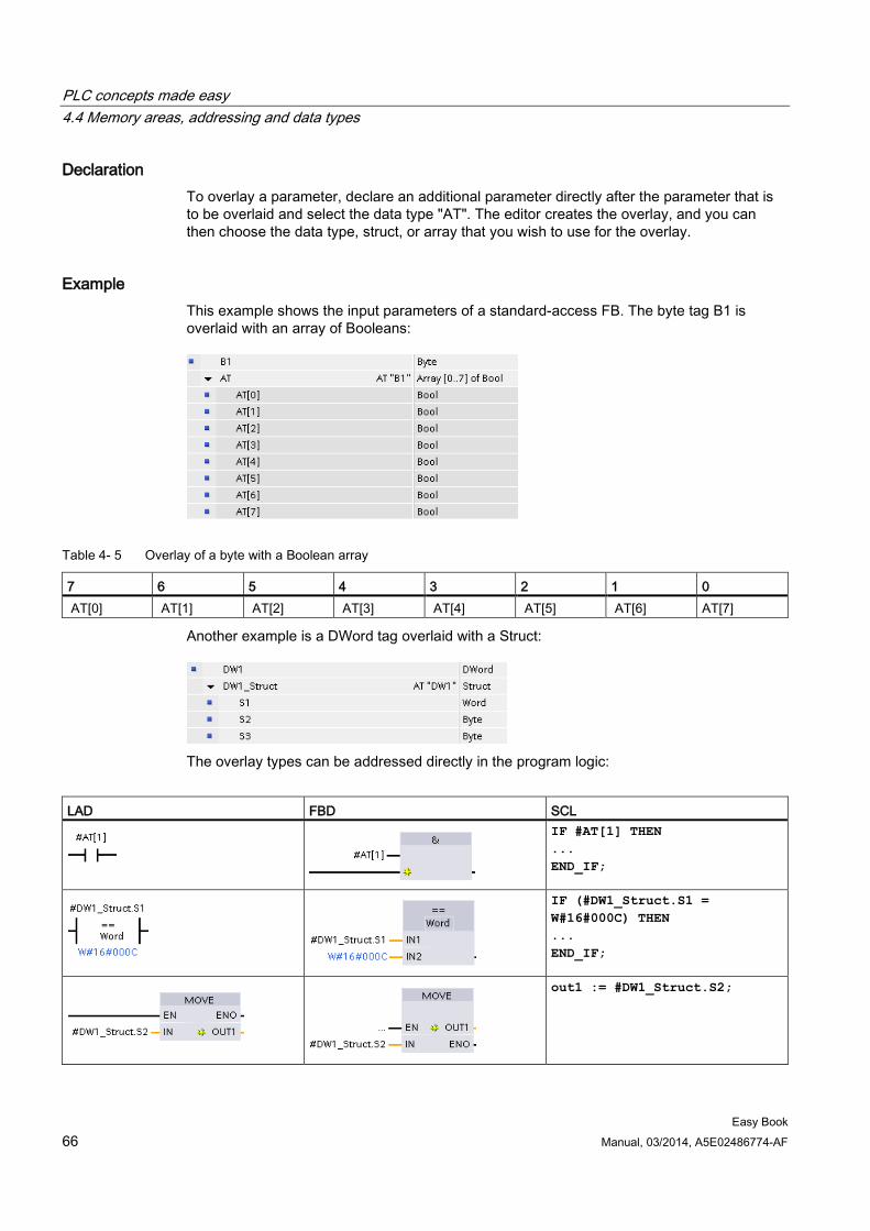
PLC concepts made easy 4.4 Memory areas, addressing and data types
Easy Book 66 Manual, 03/2014, A5E02486774-AF
Declaration To overlay a parameter, declare an additional parameter directly after the parameter that is to be overlaid and select the data type "AT". The editor creates the overlay, and you can then choose the data type, struct, or array that you wish to use for the overlay.
Example This example shows the input parameters of a standard-access FB. The byte tag B1 is overlaid with an array of Booleans:
Table 4- 5 Overlay of a byte with a Boolean array
7 6 5 4 3 2 1 0 AT[0] AT[1] AT[2] AT[3] AT[4] AT[5] AT[6] AT[7]
Another example is a DWord tag overlaid with a Struct:
The overlay types can be addressed directly in the program logic:
LAD FBD SCL
IF #AT[1] THEN ... END_IF;
IF (#DW1_Struct.S1 = W#16#000C) THEN ... END_IF;
out1 := #DW1_Struct.S2;
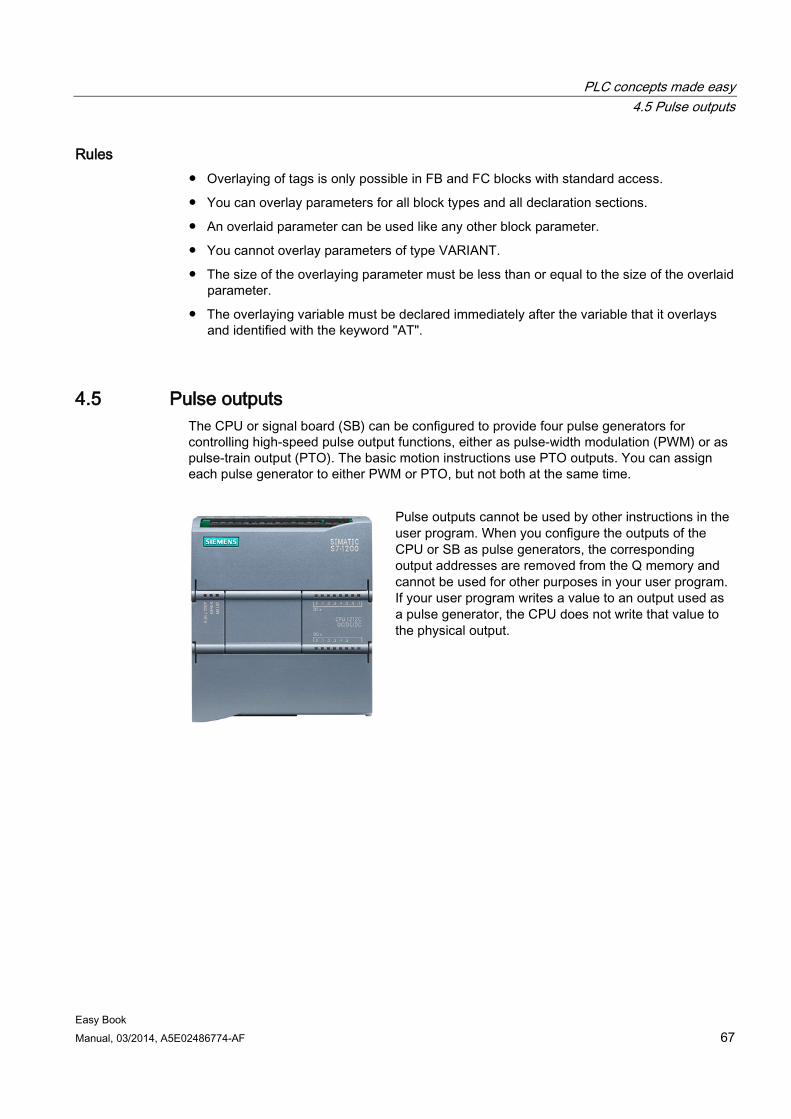
PLC concepts made easy 4.5 Pulse outputs
Easy Book Manual, 03/2014, A5E02486774-AF 67
Rules ● Overlaying of tags is only possible in FB and FC blocks with standard access.
● You can overlay parameters for all block types and all declaration sections.
● An overlaid parameter can be used like any other block parameter.
● You cannot overlay parameters of type VARIANT.
● The size of the overlaying parameter must be less than or equal to the size of the overlaid parameter.
● The overlaying variable must be declared immediately after the variable that it overlays and identified with the keyword "AT".
4.5 Pulse outputs The CPU or signal board (SB) can be configured to provide four pulse generators for controlling high-speed pulse output functions, either as pulse-width modulation (PWM) or as pulse-train output (PTO). The basic motion instructions use PTO outputs. You can assign each pulse generator to either PWM or PTO, but not both at the same time.
Pulse outputs cannot be used by other instructions in the user program. When you configure the outputs of the CPU or SB as pulse generators, the corresponding output addresses are removed from the Q memory and cannot be used for other purposes in your user program. If your user program writes a value to an output used as a pulse generator, the CPU does not write that value to the physical output.
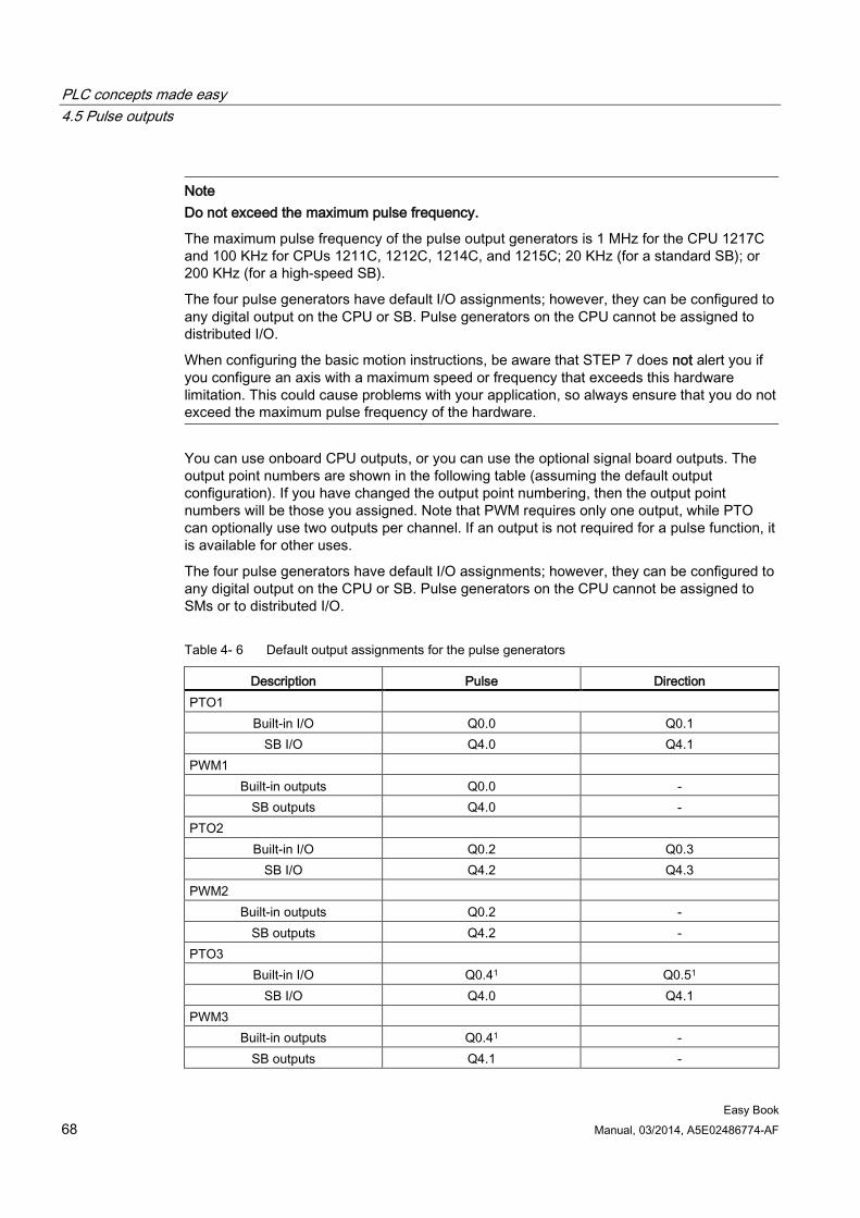
PLC concepts made easy 4.5 Pulse outputs
Easy Book 68 Manual, 03/2014, A5E02486774-AF
Note Do not exceed the maximum pulse frequency.
The maximum pulse frequency of the pulse output generators is 1 MHz for the CPU 1217C and 100 KHz for CPUs 1211C, 1212C, 1214C, and 1215C; 20 KHz (for a standard SB); or 200 KHz (for a high-speed SB).
The four pulse generators have default I/O assignments; however, they can be configured to any digital output on the CPU or SB. Pulse generators on the CPU cannot be assigned to distributed I/O.
When configuring the basic motion instructions, be aware that STEP 7 does not alert you if you configure an axis with a maximum speed or frequency that exceeds this hardware limitation. This could cause problems with your application, so always ensure that you do not exceed the maximum pulse frequency of the hardware.
You can use onboard CPU outputs, or you can use the optional signal board outputs. The output point numbers are shown in the following table (assuming the default output configuration). If you have changed the output point numbering, then the output point numbers will be those you assigned. Note that PWM requires only one output, while PTO can optionally use two outputs per channel. If an output is not required for a pulse function, it is available for other uses.
The four pulse generators have default I/O assignments; however, they can be configured to any digital output on the CPU or SB. Pulse generators on the CPU cannot be assigned to SMs or to distributed I/O.
Table 4- 6 Default output assignments for the pulse generators
Description Pulse Direction PTO1
Built-in I/O Q0.0 Q0.1 SB I/O Q4.0 Q4.1
PWM1 Built-in outputs Q0.0 -
SB outputs Q4.0 - PTO2
Built-in I/O Q0.2 Q0.3 SB I/O Q4.2 Q4.3
PWM2 Built-in outputs Q0.2 -
SB outputs Q4.2 - PTO3
Built-in I/O Q0.41 Q0.51 SB I/O Q4.0 Q4.1
PWM3 Built-in outputs Q0.41 -
SB outputs Q4.1 -
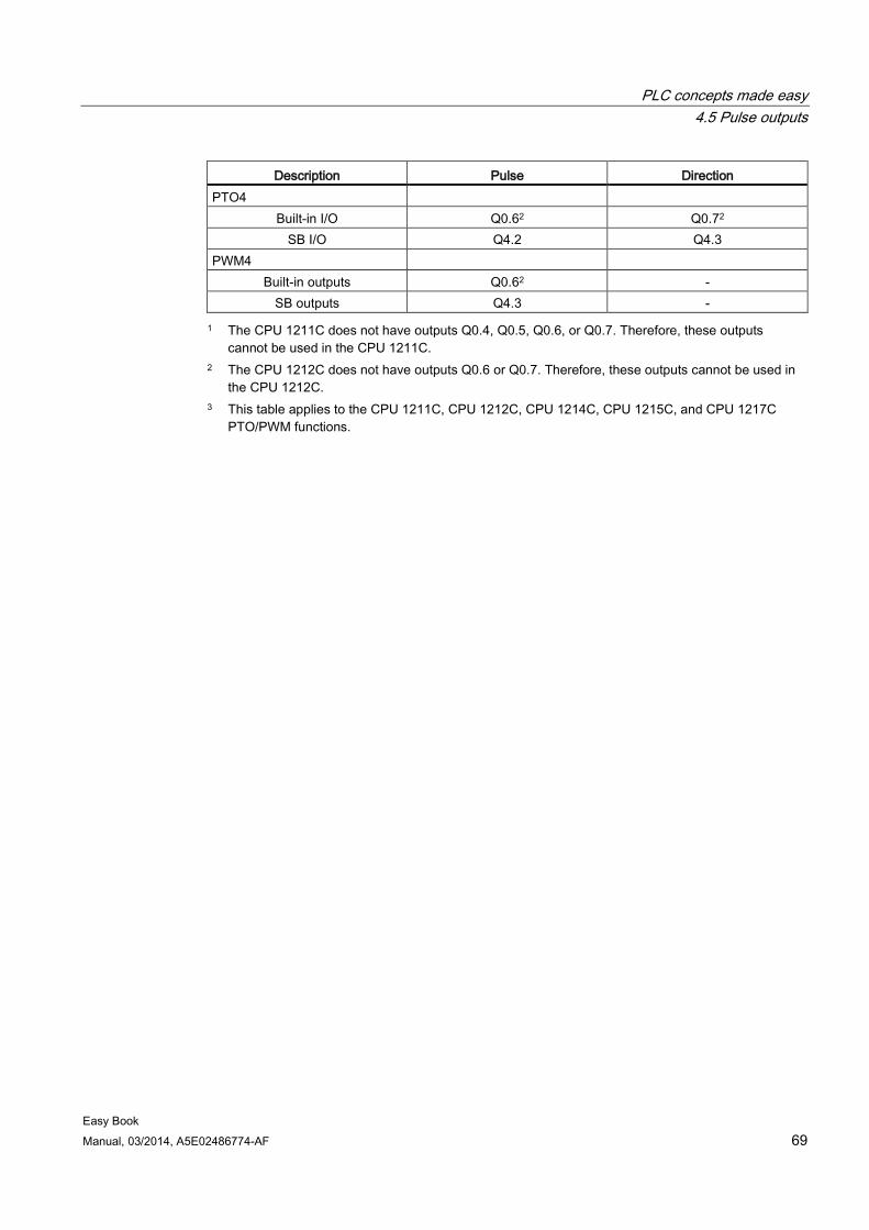
PLC concepts made easy 4.5 Pulse outputs
Easy Book Manual, 03/2014, A5E02486774-AF 69
Description Pulse Direction PTO4
Built-in I/O Q0.62 Q0.72 SB I/O Q4.2 Q4.3
PWM4 Built-in outputs Q0.62 -
SB outputs Q4.3 - 1 The CPU 1211C does not have outputs Q0.4, Q0.5, Q0.6, or Q0.7. Therefore, these outputs
cannot be used in the CPU 1211C. 2 The CPU 1212C does not have outputs Q0.6 or Q0.7. Therefore, these outputs cannot be used in
the CPU 1212C. 3 This table applies to the CPU 1211C, CPU 1212C, CPU 1214C, CPU 1215C, and CPU 1217C
PTO/PWM functions.

PLC concepts made easy 4.5 Pulse outputs
Easy Book 70 Manual, 03/2014, A5E02486774-AF
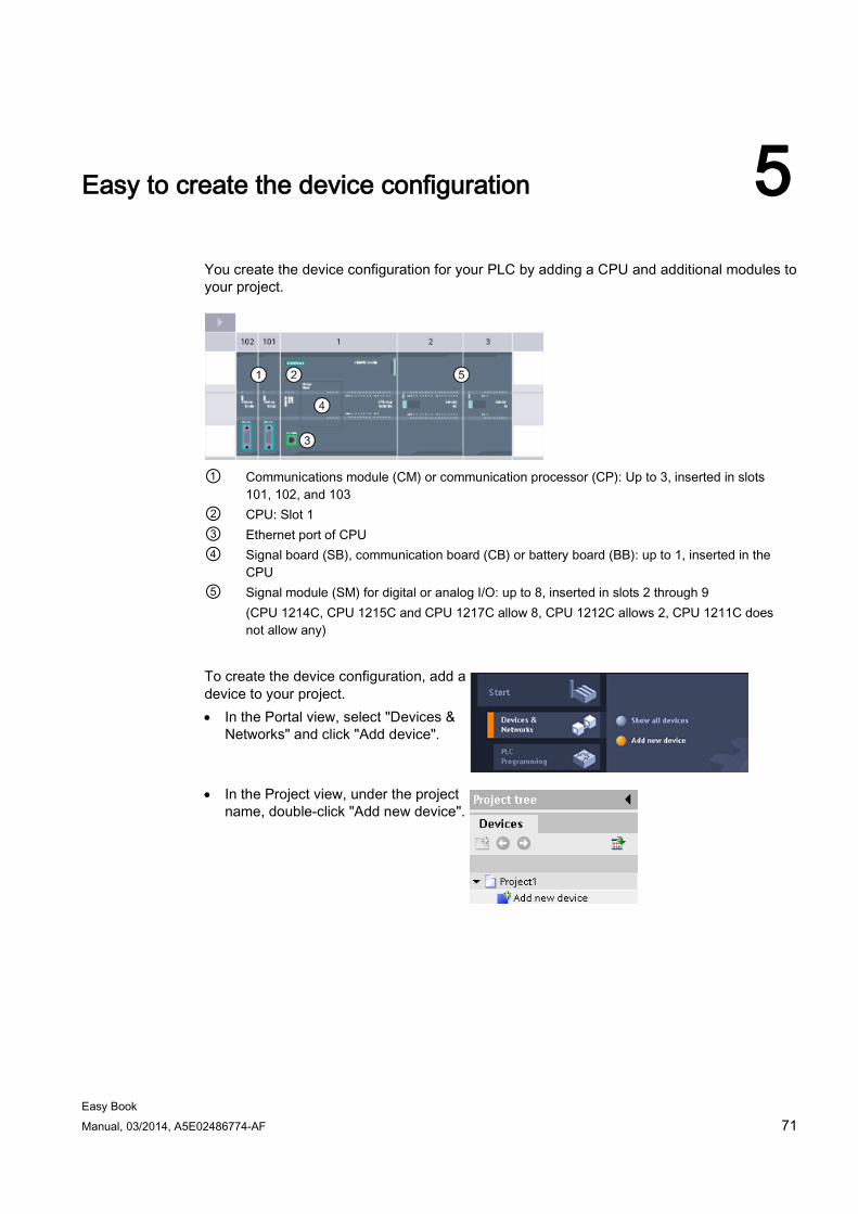
Easy Book Manual, 03/2014, A5E02486774-AF 71
Easy to create the device configuration 5
You create the device configuration for your PLC by adding a CPU and additional modules to your project.
① Communications module (CM) or communication processor (CP): Up to 3, inserted in slots
101, 102, and 103 ② CPU: Slot 1 ③ Ethernet port of CPU ④ Signal board (SB), communication board (CB) or battery board (BB): up to 1, inserted in the
CPU ⑤ Signal module (SM) for digital or analog I/O: up to 8, inserted in slots 2 through 9
(CPU 1214C, CPU 1215C and CPU 1217C allow 8, CPU 1212C allows 2, CPU 1211C does not allow any)
To create the device configuration, add a device to your project. • In the Portal view, select "Devices &
Networks" and click "Add device".
• In the Project view, under the project name, double-click "Add new device".
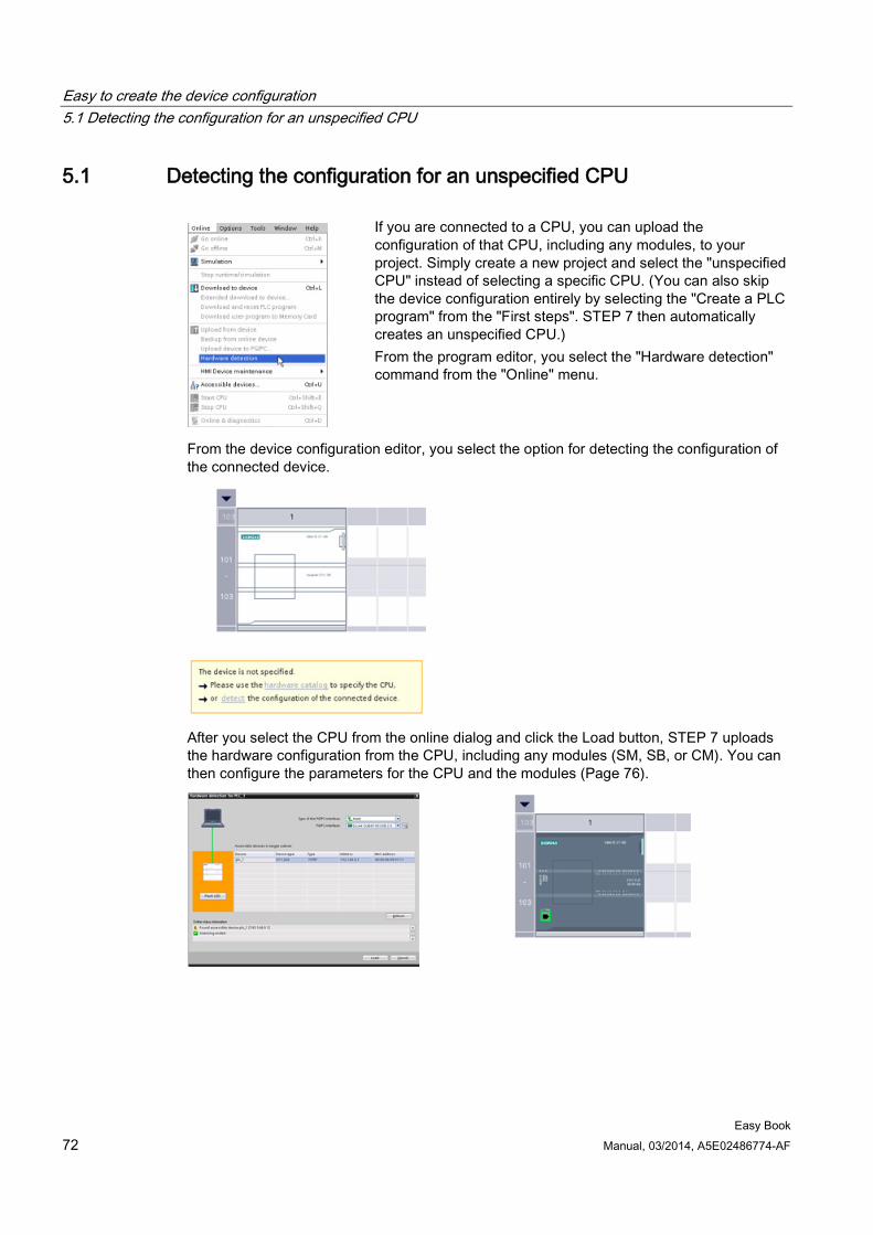
Easy to create the device configuration 5.1 Detecting the configuration for an unspecified CPU
Easy Book 72 Manual, 03/2014, A5E02486774-AF
5.1 Detecting the configuration for an unspecified CPU
If you are connected to a CPU, you can upload the configuration of that CPU, including any modules, to your project. Simply create a new project and select the "unspecified CPU" instead of selecting a specific CPU. (You can also skip the device configuration entirely by selecting the "Create a PLC program" from the "First steps". STEP 7 then automatically creates an unspecified CPU.) From the program editor, you select the "Hardware detection" command from the "Online" menu.
From the device configuration editor, you select the option for detecting the configuration of the connected device.
After you select the CPU from the online dialog and click the Load button, STEP 7 uploads the hardware configuration from the CPU, including any modules (SM, SB, or CM). You can then configure the parameters for the CPU and the modules (Page 76).
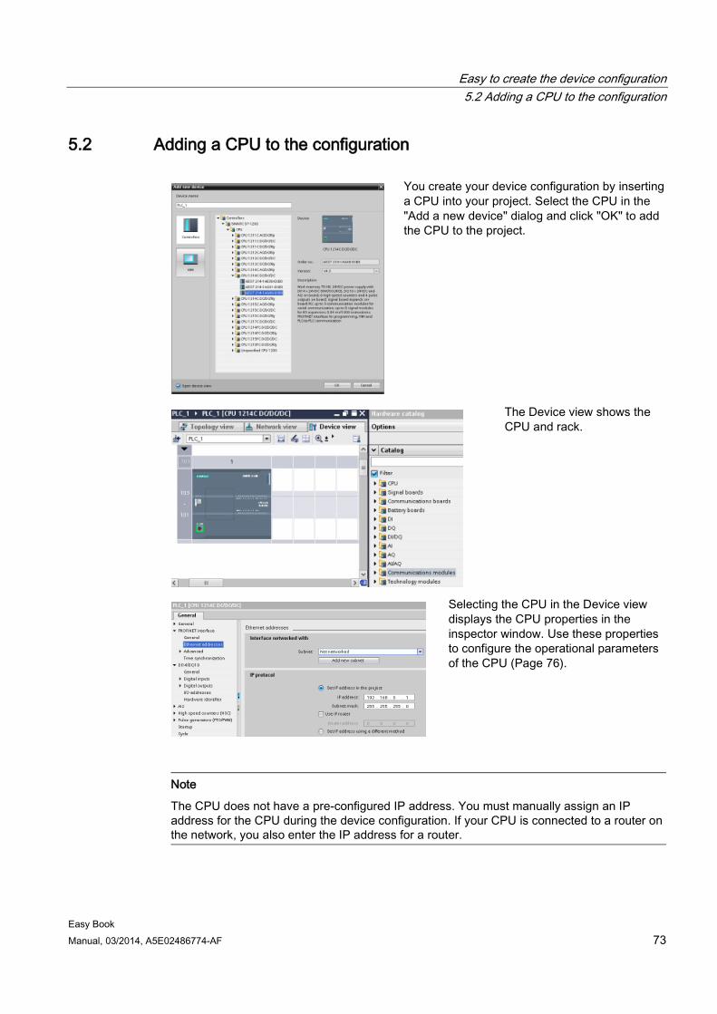
Easy to create the device configuration 5.2 Adding a CPU to the configuration
Easy Book Manual, 03/2014, A5E02486774-AF 73
5.2 Adding a CPU to the configuration
You create your device configuration by inserting a CPU into your project. Select the CPU in the "Add a new device" dialog and click "OK" to add the CPU to the project.
The Device view shows the CPU and rack.
Selecting the CPU in the Device view displays the CPU properties in the inspector window. Use these properties to configure the operational parameters of the CPU (Page 76).
Note
The CPU does not have a pre-configured IP address. You must manually assign an IP address for the CPU during the device configuration. If your CPU is connected to a router on the network, you also enter the IP address for a router.
Easy to create the device configuration 5.3 Changing a device
Easy Book 74 Manual, 03/2014, A5E02486774-AF
5.3 Changing a device You can change the device type of a configure CPU or module. From Device configuration, right-click the device and select "Change device" from the context menu. From the dialog, navigate to and select the CPU or module that you want to replace. The Change device dialog shows you combatibility information between the two devices.
Note Device exchange: replacing a V3.0 CPU with a V4.0 CPU
You can open a STEP 7 V12 project in STEP 7 V13 and replace V3.0 CPUs with V4.0 CPUs. You cannot replace CPUs that are from versions prior to V3.0. When you replace a V3.0 CPU with a V4.0 CPU, consider the differences (Page 345) in features and behavior between the two versions, and actions you must take.
If you have a project for a CPU version older than V3.0, you can upgrade that project first to V3.0 and then upgrade the V3.0 project to V4.0.
5.4 Adding modules to the configuration Use the hardware catalog to add modules to the CPU:
● Signal module (SM) provides additional digital or analog I/O points. These modules are connected to the right side of the CPU.
● Signal board (SB) provides just a few additional I/O points for the CPU. The SB is installed on the front of the CPU.
● Battery Board 1297 (BB) provides long-term backup of the realtime clock. The BB is installed on the front of the CPU.
● Communication board (CB) provides an additional communication port (such as RS485). The CB is installed on the front of the CPU.
● Communication module (CM) and communication processor (CP) provide an additional communication port, such as for PROFIBUS or GPRS. These modules are connected to the left side of the CPU.
To insert a module into the device configuration, select the module in the hardware catalog and either double-click or drag the module to the highlighted slot. You must add the modules to the device configuration and download the hardware configuration to the CPU for the modules to be functional.
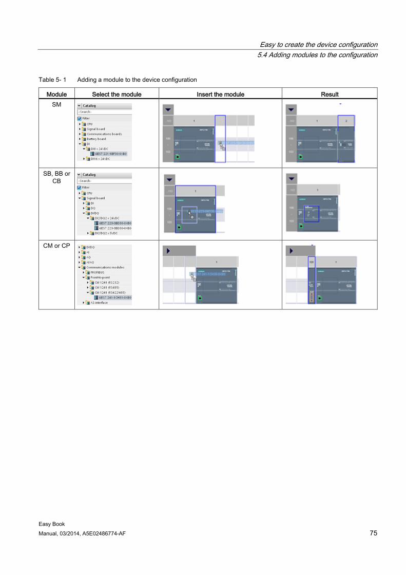
Easy to create the device configuration 5.4 Adding modules to the configuration
Easy Book Manual, 03/2014, A5E02486774-AF 75
Table 5- 1 Adding a module to the device configuration
Module Select the module Insert the module Result SM
SB, BB or
CB
CM or CP
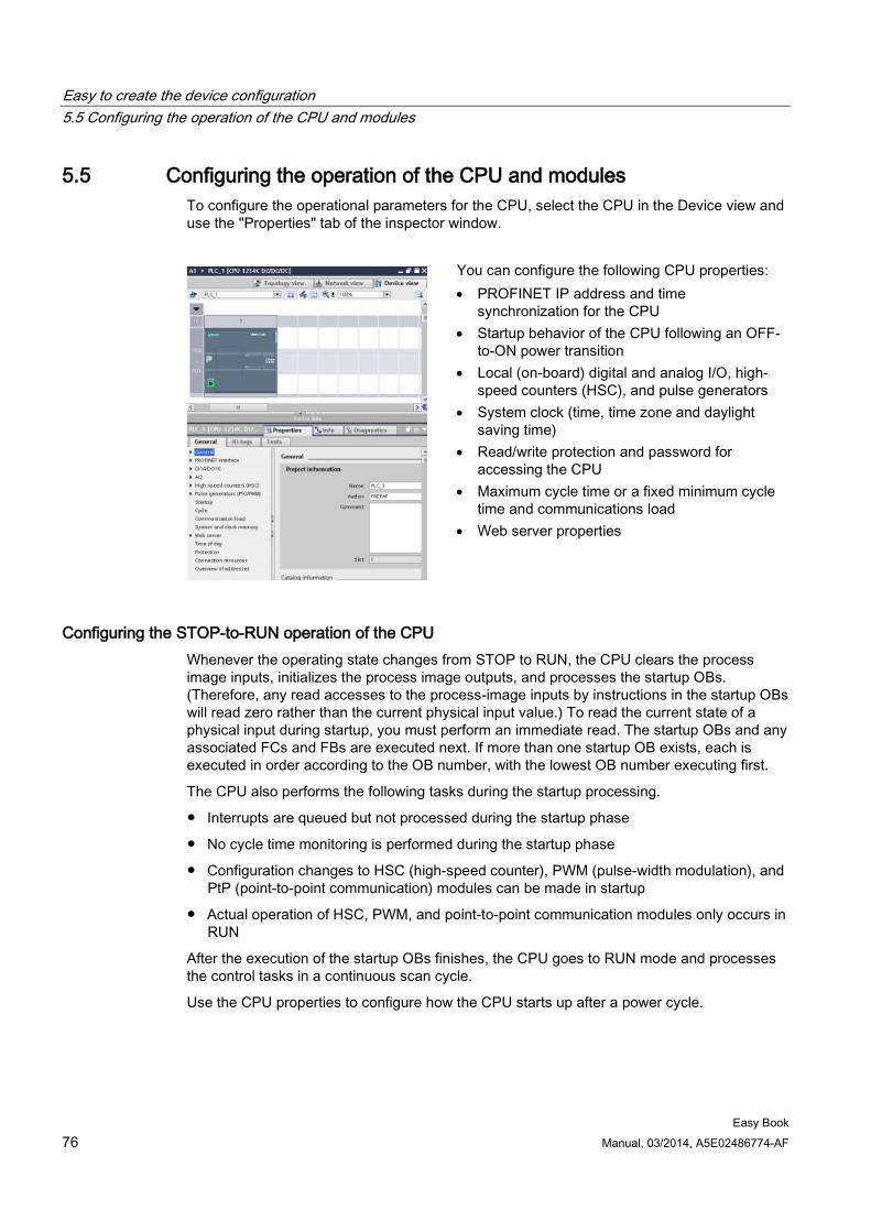
Easy to create the device configuration 5.5 Configuring the operation of the CPU and modules
Easy Book 76 Manual, 03/2014, A5E02486774-AF
5.5 Configuring the operation of the CPU and modules To configure the operational parameters for the CPU, select the CPU in the Device view and use the "Properties" tab of the inspector window.
You can configure the following CPU properties: • PROFINET IP address and time
synchronization for the CPU • Startup behavior of the CPU following an OFF-
to-ON power transition • Local (on-board) digital and analog I/O, high-
speed counters (HSC), and pulse generators • System clock (time, time zone and daylight
saving time) • Read/write protection and password for
accessing the CPU • Maximum cycle time or a fixed minimum cycle
time and communications load • Web server properties
Configuring the STOP-to-RUN operation of the CPU Whenever the operating state changes from STOP to RUN, the CPU clears the process image inputs, initializes the process image outputs, and processes the startup OBs. (Therefore, any read accesses to the process-image inputs by instructions in the startup OBs will read zero rather than the current physical input value.) To read the current state of a physical input during startup, you must perform an immediate read. The startup OBs and any associated FCs and FBs are executed next. If more than one startup OB exists, each is executed in order according to the OB number, with the lowest OB number executing first.
The CPU also performs the following tasks during the startup processing.
● Interrupts are queued but not processed during the startup phase
● No cycle time monitoring is performed during the startup phase
● Configuration changes to HSC (high-speed counter), PWM (pulse-width modulation), and PtP (point-to-point communication) modules can be made in startup
● Actual operation of HSC, PWM, and point-to-point communication modules only occurs in RUN
After the execution of the startup OBs finishes, the CPU goes to RUN mode and processes the control tasks in a continuous scan cycle.
Use the CPU properties to configure how the CPU starts up after a power cycle.
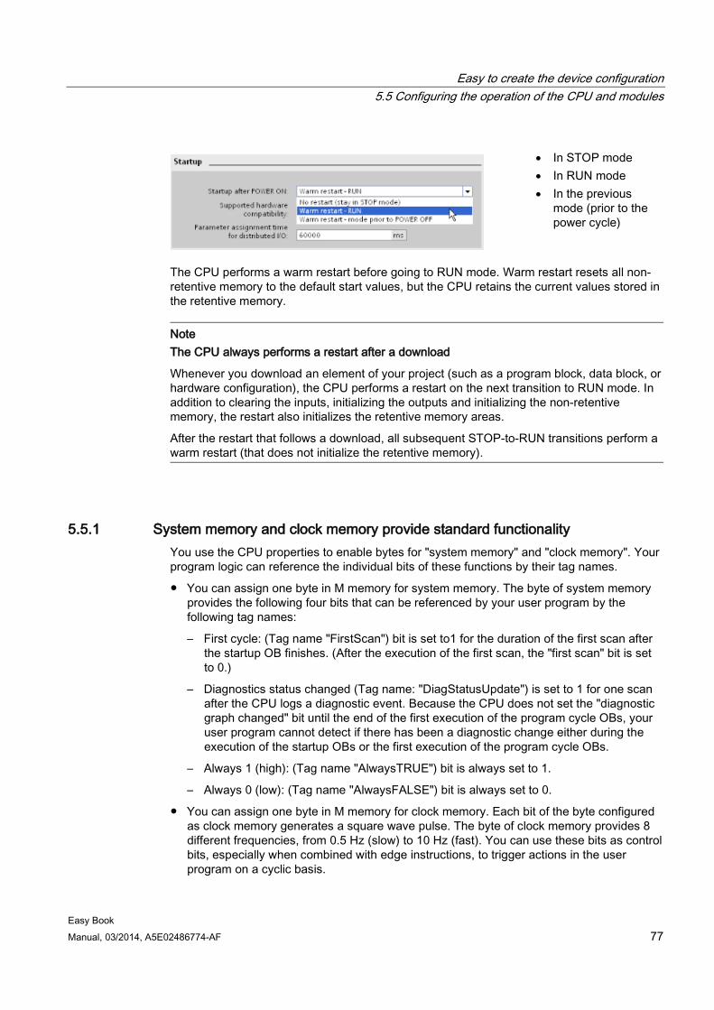
Easy to create the device configuration 5.5 Configuring the operation of the CPU and modules
Easy Book Manual, 03/2014, A5E02486774-AF 77
• In STOP mode • In RUN mode • In the previous
mode (prior to the power cycle)
The CPU performs a warm restart before going to RUN mode. Warm restart resets all non-retentive memory to the default start values, but the CPU retains the current values stored in the retentive memory.
Note The CPU always performs a restart after a download
Whenever you download an element of your project (such as a program block, data block, or hardware configuration), the CPU performs a restart on the next transition to RUN mode. In addition to clearing the inputs, initializing the outputs and initializing the non-retentive memory, the restart also initializes the retentive memory areas.
After the restart that follows a download, all subsequent STOP-to-RUN transitions perform a warm restart (that does not initialize the retentive memory).
5.5.1 System memory and clock memory provide standard functionality You use the CPU properties to enable bytes for "system memory" and "clock memory". Your program logic can reference the individual bits of these functions by their tag names.
● You can assign one byte in M memory for system memory. The byte of system memory provides the following four bits that can be referenced by your user program by the following tag names:
– First cycle: (Tag name "FirstScan") bit is set to1 for the duration of the first scan after the startup OB finishes. (After the execution of the first scan, the "first scan" bit is set to 0.)
– Diagnostics status changed (Tag name: "DiagStatusUpdate") is set to 1 for one scan after the CPU logs a diagnostic event. Because the CPU does not set the "diagnostic graph changed" bit until the end of the first execution of the program cycle OBs, your user program cannot detect if there has been a diagnostic change either during the execution of the startup OBs or the first execution of the program cycle OBs.
– Always 1 (high): (Tag name "AlwaysTRUE") bit is always set to 1.
– Always 0 (low): (Tag name "AlwaysFALSE") bit is always set to 0.
● You can assign one byte in M memory for clock memory. Each bit of the byte configured as clock memory generates a square wave pulse. The byte of clock memory provides 8 different frequencies, from 0.5 Hz (slow) to 10 Hz (fast). You can use these bits as control bits, especially when combined with edge instructions, to trigger actions in the user program on a cyclic basis.
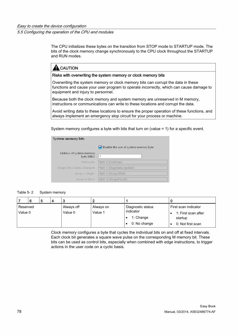
Easy to create the device configuration 5.5 Configuring the operation of the CPU and modules
Easy Book 78 Manual, 03/2014, A5E02486774-AF
The CPU initializes these bytes on the transition from STOP mode to STARTUP mode. The bits of the clock memory change synchronously to the CPU clock throughout the STARTUP and RUN modes.
CAUTION
Risks with overwriting the system memory or clock memory bits
Overwriting the system memory or clock memory bits can corrupt the data in these functions and cause your user program to operate incorrectly, which can cause damage to equipment and injury to personnel.
Because both the clock memory and system memory are unreserved in M memory, instructions or communications can write to these locations and corrupt the data.
Avoid writing data to these locations to ensure the proper operation of these functions, and always implement an emergency stop circuit for your process or machine.
System memory configures a byte with bits that turn on (value = 1) for a specific event.
Table 5- 2 System memory
7 6 5 4 3 2 1 0 Reserved Value 0
Always off Value 0
Always on Value 1
Diagnostic status indicator • 1: Change • 0: No change
First scan indicator • 1: First scan after
startup • 0: Not first scan
Clock memory configures a byte that cycles the individual bits on and off at fixed intervals. Each clock bit generates a square wave pulse on the corresponding M memory bit. These bits can be used as control bits, especially when combined with edge instructions, to trigger actions in the user code on a cyclic basis.
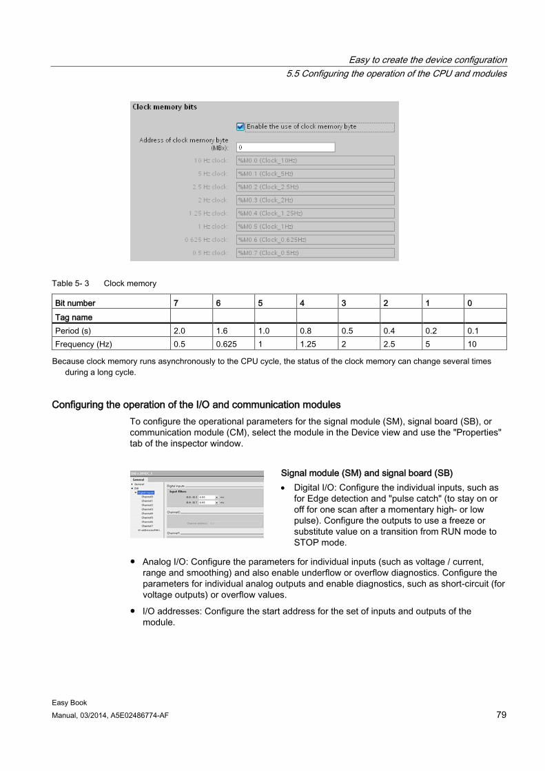
Easy to create the device configuration 5.5 Configuring the operation of the CPU and modules
Easy Book Manual, 03/2014, A5E02486774-AF 79
Table 5- 3 Clock memory
Bit number 7 6 5 4 3 2 1 0 Tag name Period (s) 2.0 1.6 1.0 0.8 0.5 0.4 0.2 0.1 Frequency (Hz) 0.5 0.625 1 1.25 2 2.5 5 10 Because clock memory runs asynchronously to the CPU cycle, the status of the clock memory can change several times
during a long cycle.
Configuring the operation of the I/O and communication modules To configure the operational parameters for the signal module (SM), signal board (SB), or communication module (CM), select the module in the Device view and use the "Properties" tab of the inspector window.
Signal module (SM) and signal board (SB) • Digital I/O: Configure the individual inputs, such as
for Edge detection and "pulse catch" (to stay on or off for one scan after a momentary high- or low pulse). Configure the outputs to use a freeze or substitute value on a transition from RUN mode to STOP mode.
● Analog I/O: Configure the parameters for individual inputs (such as voltage / current, range and smoothing) and also enable underflow or overflow diagnostics. Configure the parameters for individual analog outputs and enable diagnostics, such as short-circuit (for voltage outputs) or overflow values.
● I/O addresses: Configure the start address for the set of inputs and outputs of the module.
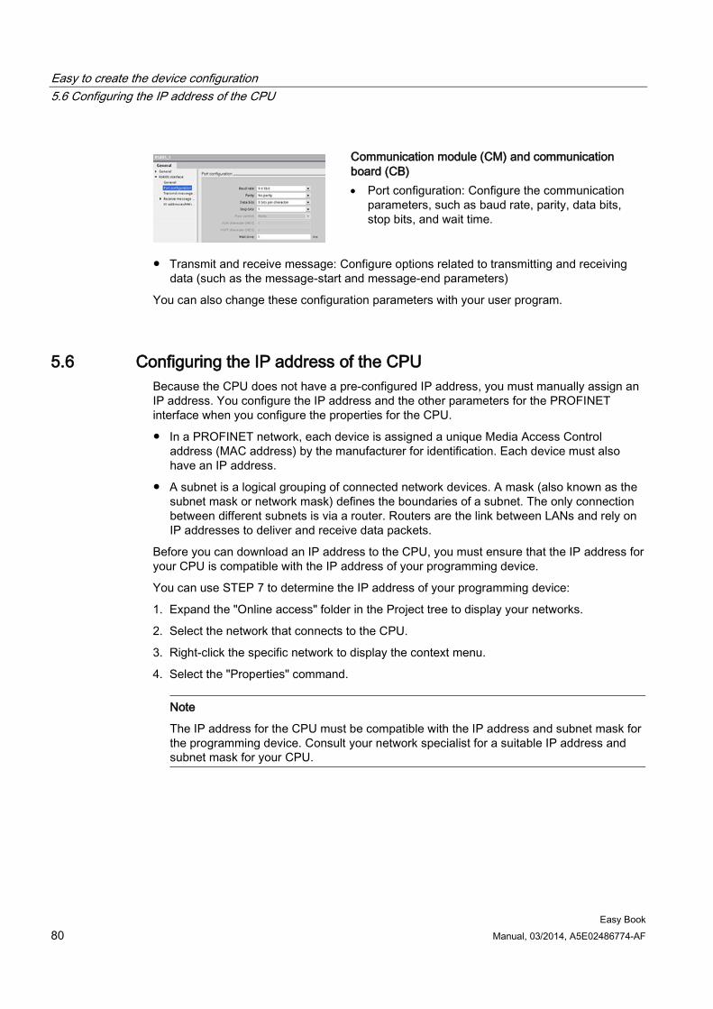
Easy to create the device configuration 5.6 Configuring the IP address of the CPU
Easy Book 80 Manual, 03/2014, A5E02486774-AF
Communication module (CM) and communication board (CB) • Port configuration: Configure the communication
parameters, such as baud rate, parity, data bits, stop bits, and wait time.
● Transmit and receive message: Configure options related to transmitting and receiving data (such as the message-start and message-end parameters)
You can also change these configuration parameters with your user program.
5.6 Configuring the IP address of the CPU Because the CPU does not have a pre-configured IP address, you must manually assign an IP address. You configure the IP address and the other parameters for the PROFINET interface when you configure the properties for the CPU.
● In a PROFINET network, each device is assigned a unique Media Access Control address (MAC address) by the manufacturer for identification. Each device must also have an IP address.
● A subnet is a logical grouping of connected network devices. A mask (also known as the subnet mask or network mask) defines the boundaries of a subnet. The only connection between different subnets is via a router. Routers are the link between LANs and rely on IP addresses to deliver and receive data packets.
Before you can download an IP address to the CPU, you must ensure that the IP address for your CPU is compatible with the IP address of your programming device.
You can use STEP 7 to determine the IP address of your programming device:
1. Expand the "Online access" folder in the Project tree to display your networks.
2. Select the network that connects to the CPU.
3. Right-click the specific network to display the context menu.
4. Select the "Properties" command.
Note
The IP address for the CPU must be compatible with the IP address and subnet mask for the programming device. Consult your network specialist for a suitable IP address and subnet mask for your CPU.
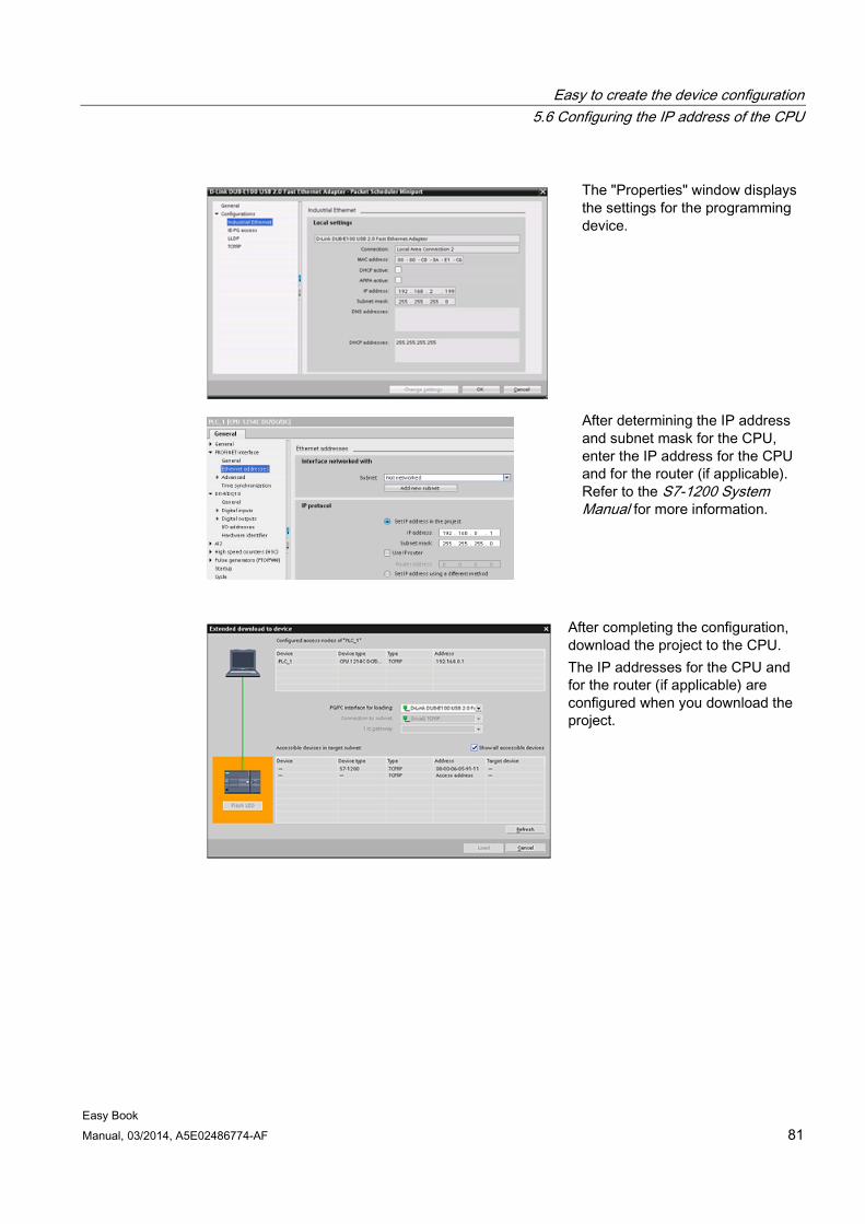
Easy to create the device configuration 5.6 Configuring the IP address of the CPU
Easy Book Manual, 03/2014, A5E02486774-AF 81
The "Properties" window displays the settings for the programming device.
After determining the IP address and subnet mask for the CPU, enter the IP address for the CPU and for the router (if applicable). Refer to the S7-1200 System Manual for more information.
After completing the configuration, download the project to the CPU. The IP addresses for the CPU and for the router (if applicable) are configured when you download the project.
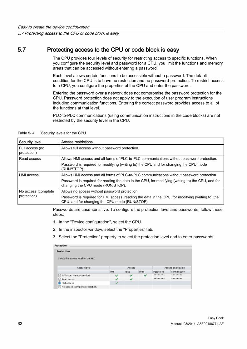
Easy to create the device configuration 5.7 Protecting access to the CPU or code block is easy
Easy Book 82 Manual, 03/2014, A5E02486774-AF
5.7 Protecting access to the CPU or code block is easy The CPU provides four levels of security for restricting access to specific functions. When you configure the security level and password for a CPU, you limit the functions and memory areas that can be accessed without entering a password.
Each level allows certain functions to be accessible without a password. The default condition for the CPU is to have no restriction and no password-protection. To restrict access to a CPU, you configure the properties of the CPU and enter the password.
Entering the password over a network does not compromise the password protection for the CPU. Password protection does not apply to the execution of user program instructions including communication functions. Entering the correct password provides access to all of the functions at that level.
PLC-to-PLC communications (using communication instructions in the code blocks) are not restricted by the security level in the CPU.
Table 5- 4 Security levels for the CPU
Security level Access restrictions Full access (no protection)
Allows full access without password protection.
Read access Allows HMI access and all forms of PLC-to-PLC communications without password protection. Password is required for modifying (writing to) the CPU and for changing the CPU mode (RUN/STOP).
HMI access Allows HMI access and all forms of PLC-to-PLC communications without password protection. Password is required for reading the data in the CPU, for modifying (writing to) the CPU, and for changing the CPU mode (RUN/STOP).
No access (complete protection)
Allows no access without password protection. Password is required for HMI access, reading the data in the CPU, for modifying (writing to) the CPU, and for changing the CPU mode (RUN/STOP)
Passwords are case-sensitive. To configure the protection level and passwords, follow these steps:
1. In the "Device configuration", select the CPU.
2. In the inspector window, select the "Properties" tab.
3. Select the "Protection" property to select the protection level and to enter passwords.
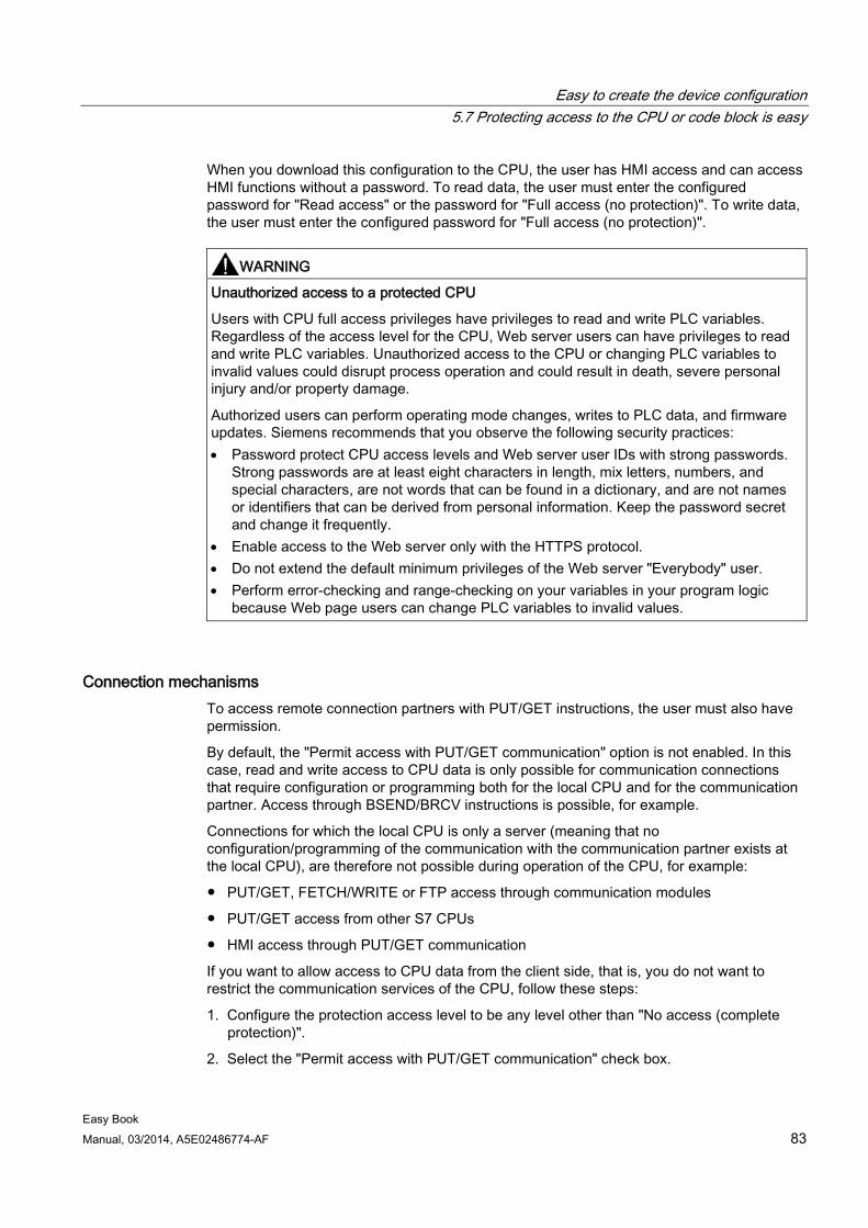
Easy to create the device configuration 5.7 Protecting access to the CPU or code block is easy
Easy Book Manual, 03/2014, A5E02486774-AF 83
When you download this configuration to the CPU, the user has HMI access and can access HMI functions without a password. To read data, the user must enter the configured password for "Read access" or the password for "Full access (no protection)". To write data, the user must enter the configured password for "Full access (no protection)".
WARNING
Unauthorized access to a protected CPU
Users with CPU full access privileges have privileges to read and write PLC variables. Regardless of the access level for the CPU, Web server users can have privileges to read and write PLC variables. Unauthorized access to the CPU or changing PLC variables to invalid values could disrupt process operation and could result in death, severe personal injury and/or property damage.
Authorized users can perform operating mode changes, writes to PLC data, and firmware updates. Siemens recommends that you observe the following security practices: • Password protect CPU access levels and Web server user IDs with strong passwords.
Strong passwords are at least eight characters in length, mix letters, numbers, and special characters, are not words that can be found in a dictionary, and are not names or identifiers that can be derived from personal information. Keep the password secret and change it frequently.
• Enable access to the Web server only with the HTTPS protocol. • Do not extend the default minimum privileges of the Web server "Everybody" user. • Perform error-checking and range-checking on your variables in your program logic
because Web page users can change PLC variables to invalid values.
Connection mechanisms To access remote connection partners with PUT/GET instructions, the user must also have permission.
By default, the "Permit access with PUT/GET communication" option is not enabled. In this case, read and write access to CPU data is only possible for communication connections that require configuration or programming both for the local CPU and for the communication partner. Access through BSEND/BRCV instructions is possible, for example.
Connections for which the local CPU is only a server (meaning that no configuration/programming of the communication with the communication partner exists at the local CPU), are therefore not possible during operation of the CPU, for example:
● PUT/GET, FETCH/WRITE or FTP access through communication modules
● PUT/GET access from other S7 CPUs
● HMI access through PUT/GET communication
If you want to allow access to CPU data from the client side, that is, you do not want to restrict the communication services of the CPU, follow these steps:
1. Configure the protection access level to be any level other than "No access (complete protection)".
2. Select the "Permit access with PUT/GET communication" check box.
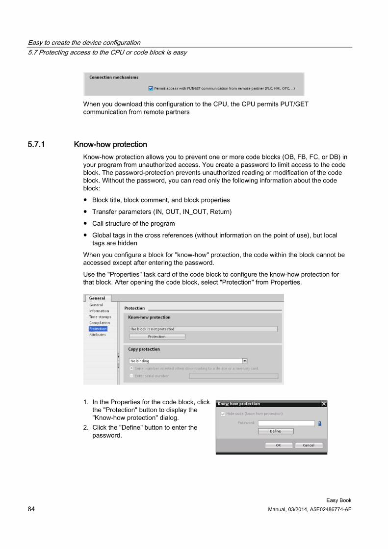
Easy to create the device configuration 5.7 Protecting access to the CPU or code block is easy
Easy Book 84 Manual, 03/2014, A5E02486774-AF
When you download this configuration to the CPU, the CPU permits PUT/GET communication from remote partners
5.7.1 Know-how protection Know-how protection allows you to prevent one or more code blocks (OB, FB, FC, or DB) in your program from unauthorized access. You create a password to limit access to the code block. The password-protection prevents unauthorized reading or modification of the code block. Without the password, you can read only the following information about the code block:
● Block title, block comment, and block properties
● Transfer parameters (IN, OUT, IN_OUT, Return)
● Call structure of the program
● Global tags in the cross references (without information on the point of use), but local tags are hidden
When you configure a block for "know-how" protection, the code within the block cannot be accessed except after entering the password.
Use the "Properties" task card of the code block to configure the know-how protection for that block. After opening the code block, select "Protection" from Properties.
1. In the Properties for the code block, click
the "Protection" button to display the "Know-how protection" dialog.
2. Click the "Define" button to enter the password.
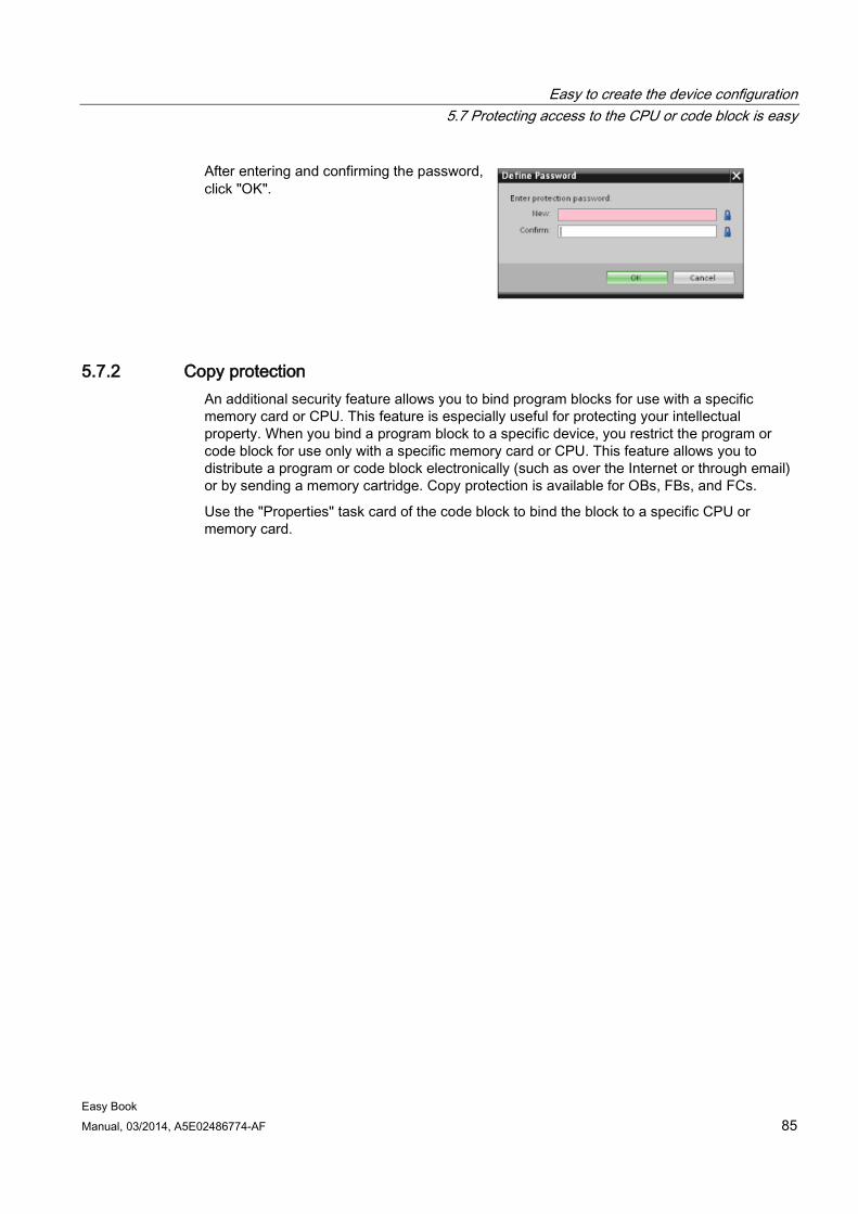
Easy to create the device configuration 5.7 Protecting access to the CPU or code block is easy
Easy Book Manual, 03/2014, A5E02486774-AF 85
After entering and confirming the password, click "OK".
5.7.2 Copy protection An additional security feature allows you to bind program blocks for use with a specific memory card or CPU. This feature is especially useful for protecting your intellectual property. When you bind a program block to a specific device, you restrict the program or code block for use only with a specific memory card or CPU. This feature allows you to distribute a program or code block electronically (such as over the Internet or through email) or by sending a memory cartridge. Copy protection is available for OBs, FBs, and FCs.
Use the "Properties" task card of the code block to bind the block to a specific CPU or memory card.
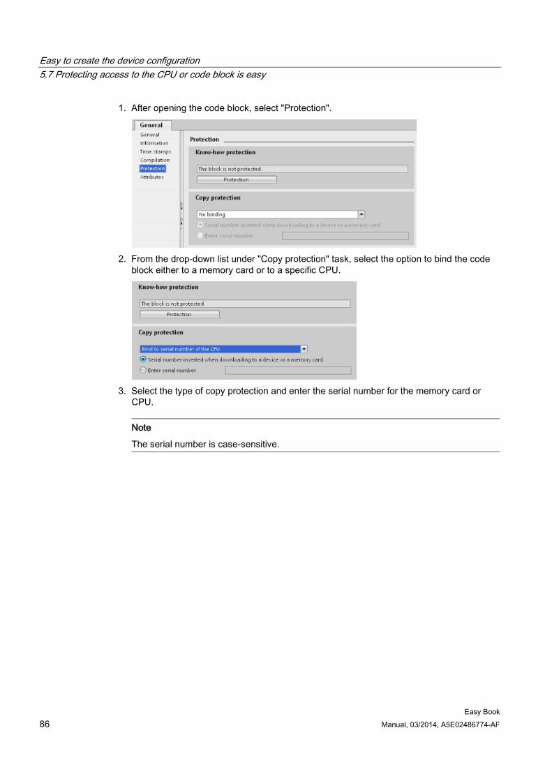
Easy to create the device configuration 5.7 Protecting access to the CPU or code block is easy
Easy Book 86 Manual, 03/2014, A5E02486774-AF
1. After opening the code block, select "Protection".
2. From the drop-down list under "Copy protection" task, select the option to bind the code
block either to a memory card or to a specific CPU.
3. Select the type of copy protection and enter the serial number for the memory card or
CPU.
Note
The serial number is case-sensitive.
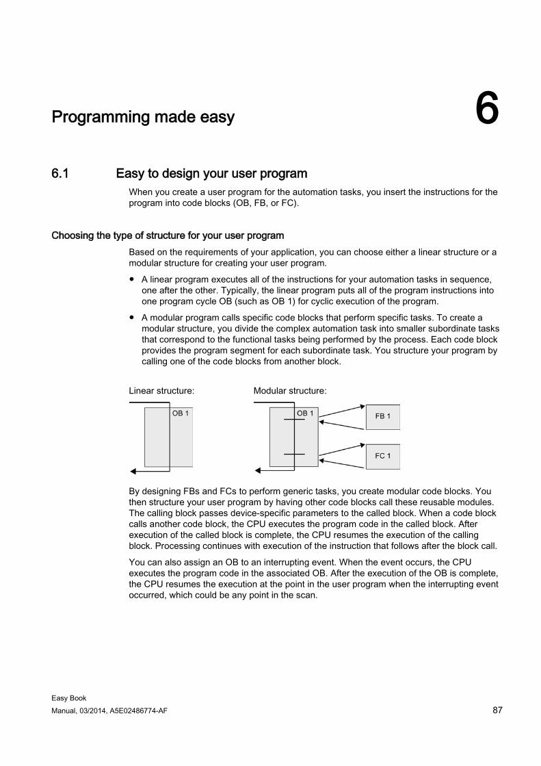
Easy Book Manual, 03/2014, A5E02486774-AF 87
Programming made easy 6 6.1 Easy to design your user program
When you create a user program for the automation tasks, you insert the instructions for the program into code blocks (OB, FB, or FC).
Choosing the type of structure for your user program Based on the requirements of your application, you can choose either a linear structure or a modular structure for creating your user program.
● A linear program executes all of the instructions for your automation tasks in sequence, one after the other. Typically, the linear program puts all of the program instructions into one program cycle OB (such as OB 1) for cyclic execution of the program.
● A modular program calls specific code blocks that perform specific tasks. To create a modular structure, you divide the complex automation task into smaller subordinate tasks that correspond to the functional tasks being performed by the process. Each code block provides the program segment for each subordinate task. You structure your program by calling one of the code blocks from another block.
Linear structure: Modular structure:
By designing FBs and FCs to perform generic tasks, you create modular code blocks. You then structure your user program by having other code blocks call these reusable modules. The calling block passes device-specific parameters to the called block. When a code block calls another code block, the CPU executes the program code in the called block. After execution of the called block is complete, the CPU resumes the execution of the calling block. Processing continues with execution of the instruction that follows after the block call.
You can also assign an OB to an interrupting event. When the event occurs, the CPU executes the program code in the associated OB. After the execution of the OB is complete, the CPU resumes the execution at the point in the user program when the interrupting event occurred, which could be any point in the scan.
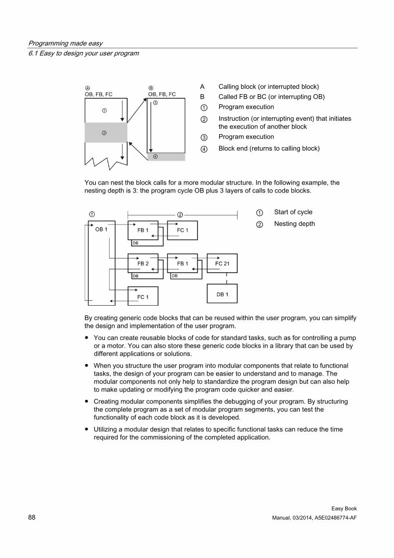
Programming made easy 6.1 Easy to design your user program
Easy Book 88 Manual, 03/2014, A5E02486774-AF
A Calling block (or interrupted block) B Called FB or BC (or interrupting OB) ① Program execution
② Instruction (or interrupting event) that initiates the execution of another block
③ Program execution
④ Block end (returns to calling block)
You can nest the block calls for a more modular structure. In the following example, the nesting depth is 3: the program cycle OB plus 3 layers of calls to code blocks.
① Start of cycle
② Nesting depth
By creating generic code blocks that can be reused within the user program, you can simplify the design and implementation of the user program.
● You can create reusable blocks of code for standard tasks, such as for controlling a pump or a motor. You can also store these generic code blocks in a library that can be used by different applications or solutions.
● When you structure the user program into modular components that relate to functional tasks, the design of your program can be easier to understand and to manage. The modular components not only help to standardize the program design but can also help to make updating or modifying the program code quicker and easier.
● Creating modular components simplifies the debugging of your program. By structuring the complete program as a set of modular program segments, you can test the functionality of each code block as it is developed.
● Utilizing a modular design that relates to specific functional tasks can reduce the time required for the commissioning of the completed application.
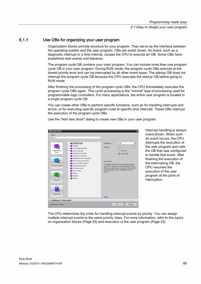
Programming made easy 6.1 Easy to design your user program
Easy Book Manual, 03/2014, A5E02486774-AF 89
6.1.1 Use OBs for organizing your user program Organization blocks provide structure for your program. They serve as the interface between the operating system and the user program. OBs are event driven. An event, such as a diagnostic interrupt or a time interval, causes the CPU to execute an OB. Some OBs have predefined start events and behavior.
The program cycle OB contains your main program. You can include more than one program cycle OB in your user program. During RUN mode, the program cycle OBs execute at the lowest priority level and can be interrupted by all other event types. The startup OB does not interrupt the program cycle OB because the CPU executes the startup OB before going to RUN mode.
After finishing the processing of the program cycle OBs, the CPU immediately executes the program cycle OBs again. This cyclic processing is the "normal" type of processing used for programmable logic controllers. For many applications, the entire user program is located in a single program cycle OB.
You can create other OBs to perform specific functions, such as for handling interrupts and errors, or for executing specific program code at specific time intervals. These OBs interrupt the execution of the program cycle OBs.
Use the "Add new block" dialog to create new OBs in your user program.
Interrupt handling is always event-driven. When such an event occurs, the CPU interrupts the execution of the user program and calls the OB that was configured to handle that event. After finishing the execution of the interrupting OB, the CPU resumes the execution of the user program at the point of interruption.
The CPU determines the order for handling interrupt events by priority. You can assign multiple interrupt events to the same priority class. For more information, refer to the topics on organization blocks (Page 55) and execution of the user program (Page 53).
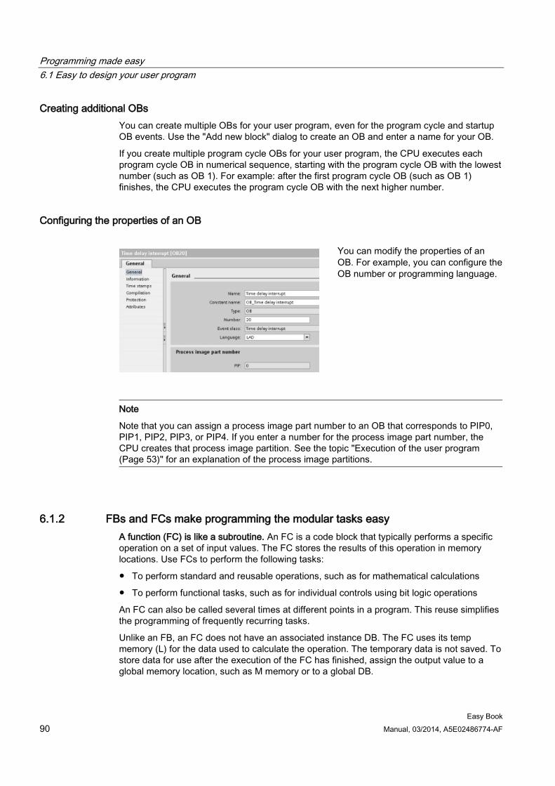
Programming made easy 6.1 Easy to design your user program
Easy Book 90 Manual, 03/2014, A5E02486774-AF
Creating additional OBs You can create multiple OBs for your user program, even for the program cycle and startup OB events. Use the "Add new block" dialog to create an OB and enter a name for your OB.
If you create multiple program cycle OBs for your user program, the CPU executes each program cycle OB in numerical sequence, starting with the program cycle OB with the lowest number (such as OB 1). For example: after the first program cycle OB (such as OB 1) finishes, the CPU executes the program cycle OB with the next higher number.
Configuring the properties of an OB
You can modify the properties of an OB. For example, you can configure the OB number or programming language.
Note
Note that you can assign a process image part number to an OB that corresponds to PIP0, PIP1, PIP2, PIP3, or PIP4. If you enter a number for the process image part number, the CPU creates that process image partition. See the topic "Execution of the user program (Page 53)" for an explanation of the process image partitions.
6.1.2 FBs and FCs make programming the modular tasks easy A function (FC) is like a subroutine. An FC is a code block that typically performs a specific operation on a set of input values. The FC stores the results of this operation in memory locations. Use FCs to perform the following tasks:
● To perform standard and reusable operations, such as for mathematical calculations
● To perform functional tasks, such as for individual controls using bit logic operations
An FC can also be called several times at different points in a program. This reuse simplifies the programming of frequently recurring tasks.
Unlike an FB, an FC does not have an associated instance DB. The FC uses its temp memory (L) for the data used to calculate the operation. The temporary data is not saved. To store data for use after the execution of the FC has finished, assign the output value to a global memory location, such as M memory or to a global DB.
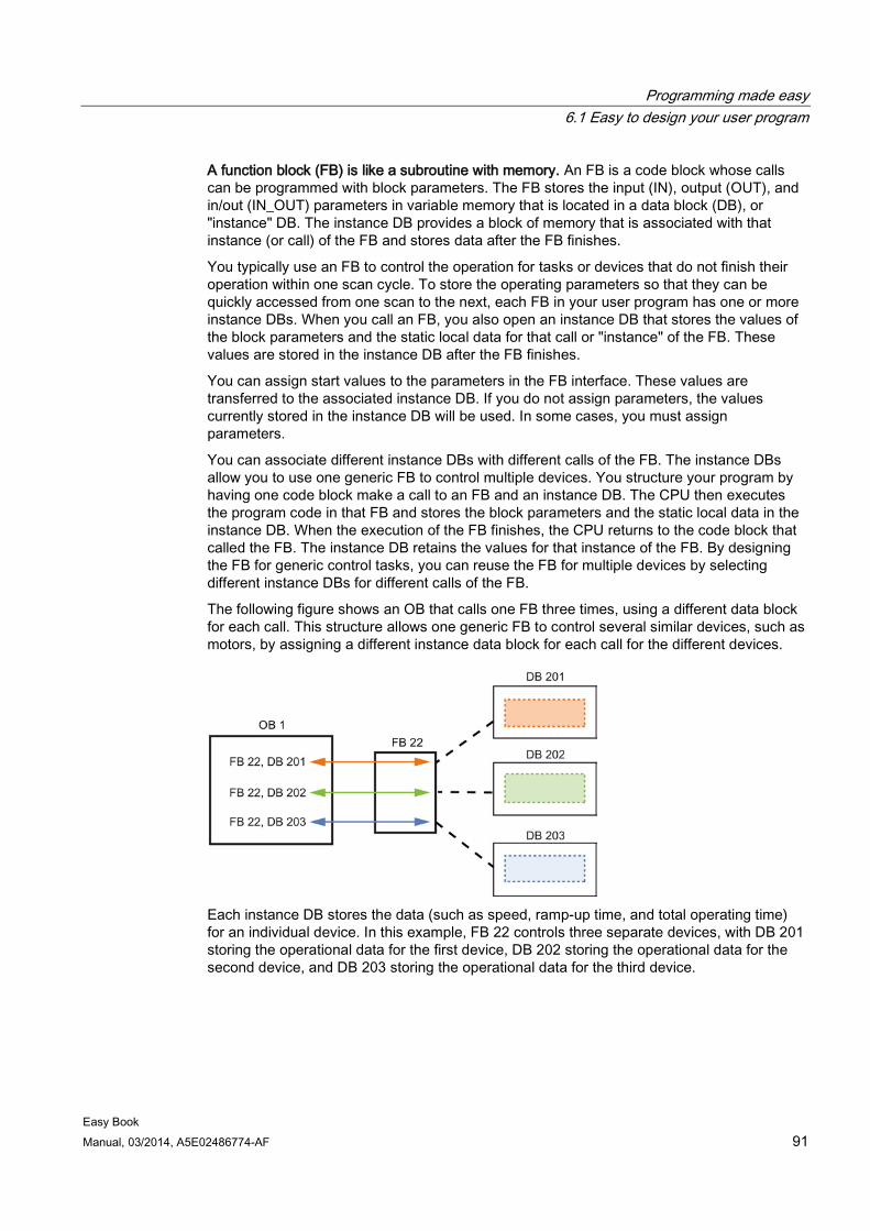
Programming made easy 6.1 Easy to design your user program
Easy Book Manual, 03/2014, A5E02486774-AF 91
A function block (FB) is like a subroutine with memory. An FB is a code block whose calls can be programmed with block parameters. The FB stores the input (IN), output (OUT), and in/out (IN_OUT) parameters in variable memory that is located in a data block (DB), or "instance" DB. The instance DB provides a block of memory that is associated with that instance (or call) of the FB and stores data after the FB finishes.
You typically use an FB to control the operation for tasks or devices that do not finish their operation within one scan cycle. To store the operating parameters so that they can be quickly accessed from one scan to the next, each FB in your user program has one or more instance DBs. When you call an FB, you also open an instance DB that stores the values of the block parameters and the static local data for that call or "instance" of the FB. These values are stored in the instance DB after the FB finishes.
You can assign start values to the parameters in the FB interface. These values are transferred to the associated instance DB. If you do not assign parameters, the values currently stored in the instance DB will be used. In some cases, you must assign parameters.
You can associate different instance DBs with different calls of the FB. The instance DBs allow you to use one generic FB to control multiple devices. You structure your program by having one code block make a call to an FB and an instance DB. The CPU then executes the program code in that FB and stores the block parameters and the static local data in the instance DB. When the execution of the FB finishes, the CPU returns to the code block that called the FB. The instance DB retains the values for that instance of the FB. By designing the FB for generic control tasks, you can reuse the FB for multiple devices by selecting different instance DBs for different calls of the FB.
The following figure shows an OB that calls one FB three times, using a different data block for each call. This structure allows one generic FB to control several similar devices, such as motors, by assigning a different instance data block for each call for the different devices.
Each instance DB stores the data (such as speed, ramp-up time, and total operating time) for an individual device. In this example, FB 22 controls three separate devices, with DB 201 storing the operational data for the first device, DB 202 storing the operational data for the second device, and DB 203 storing the operational data for the third device.
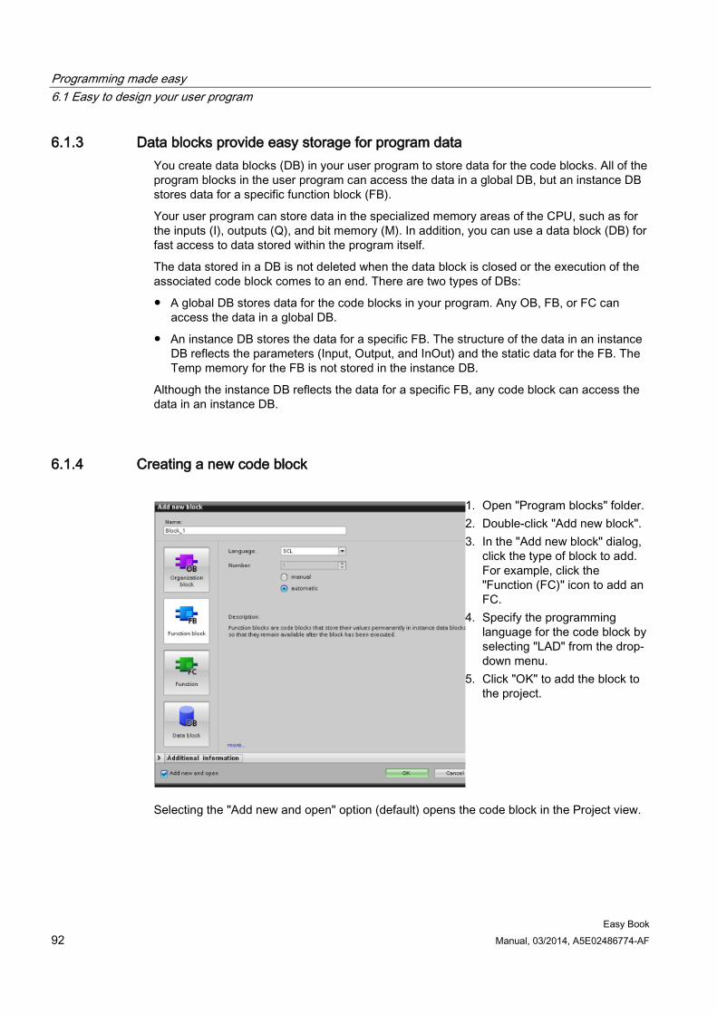
Programming made easy 6.1 Easy to design your user program
Easy Book 92 Manual, 03/2014, A5E02486774-AF
6.1.3 Data blocks provide easy storage for program data You create data blocks (DB) in your user program to store data for the code blocks. All of the program blocks in the user program can access the data in a global DB, but an instance DB stores data for a specific function block (FB).
Your user program can store data in the specialized memory areas of the CPU, such as for the inputs (I), outputs (Q), and bit memory (M). In addition, you can use a data block (DB) for fast access to data stored within the program itself.
The data stored in a DB is not deleted when the data block is closed or the execution of the associated code block comes to an end. There are two types of DBs:
● A global DB stores data for the code blocks in your program. Any OB, FB, or FC can access the data in a global DB.
● An instance DB stores the data for a specific FB. The structure of the data in an instance DB reflects the parameters (Input, Output, and InOut) and the static data for the FB. The Temp memory for the FB is not stored in the instance DB.
Although the instance DB reflects the data for a specific FB, any code block can access the data in an instance DB.
6.1.4 Creating a new code block
1. Open "Program blocks" folder. 2. Double-click "Add new block". 3. In the "Add new block" dialog,
click the type of block to add. For example, click the "Function (FC)" icon to add an FC.
4. Specify the programming language for the code block by selecting "LAD" from the drop-down menu.
5. Click "OK" to add the block to the project.
Selecting the "Add new and open" option (default) opens the code block in the Project view.
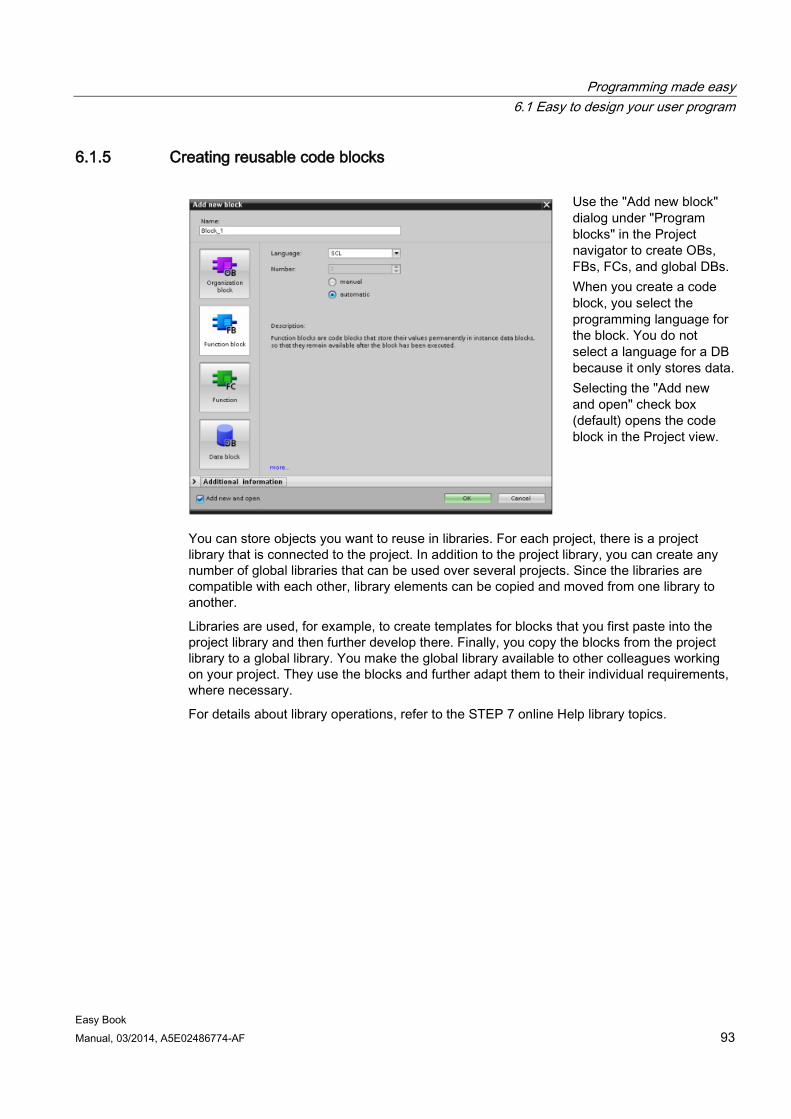
Programming made easy 6.1 Easy to design your user program
Easy Book Manual, 03/2014, A5E02486774-AF 93
6.1.5 Creating reusable code blocks
Use the "Add new block" dialog under "Program blocks" in the Project navigator to create OBs, FBs, FCs, and global DBs. When you create a code block, you select the programming language for the block. You do not select a language for a DB because it only stores data. Selecting the "Add new and open" check box (default) opens the code block in the Project view.
You can store objects you want to reuse in libraries. For each project, there is a project library that is connected to the project. In addition to the project library, you can create any number of global libraries that can be used over several projects. Since the libraries are compatible with each other, library elements can be copied and moved from one library to another.
Libraries are used, for example, to create templates for blocks that you first paste into the project library and then further develop there. Finally, you copy the blocks from the project library to a global library. You make the global library available to other colleagues working on your project. They use the blocks and further adapt them to their individual requirements, where necessary.
For details about library operations, refer to the STEP 7 online Help library topics.
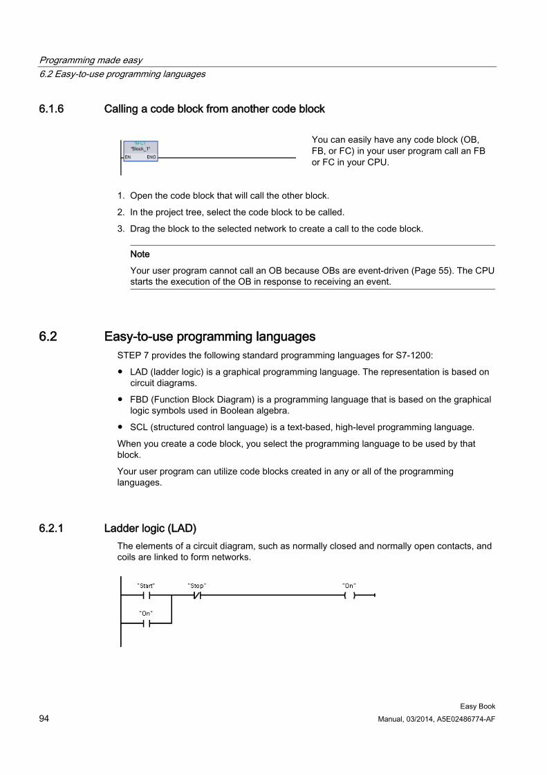
Programming made easy 6.2 Easy-to-use programming languages
Easy Book 94 Manual, 03/2014, A5E02486774-AF
6.1.6 Calling a code block from another code block
You can easily have any code block (OB, FB, or FC) in your user program call an FB or FC in your CPU.
1. Open the code block that will call the other block.
2. In the project tree, select the code block to be called.
3. Drag the block to the selected network to create a call to the code block.
Note
Your user program cannot call an OB because OBs are event-driven (Page 55). The CPU starts the execution of the OB in response to receiving an event.
6.2 Easy-to-use programming languages STEP 7 provides the following standard programming languages for S7-1200:
● LAD (ladder logic) is a graphical programming language. The representation is based on circuit diagrams.
● FBD (Function Block Diagram) is a programming language that is based on the graphical logic symbols used in Boolean algebra.
● SCL (structured control language) is a text-based, high-level programming language.
When you create a code block, you select the programming language to be used by that block.
Your user program can utilize code blocks created in any or all of the programming languages.
6.2.1 Ladder logic (LAD) The elements of a circuit diagram, such as normally closed and normally open contacts, and coils are linked to form networks.
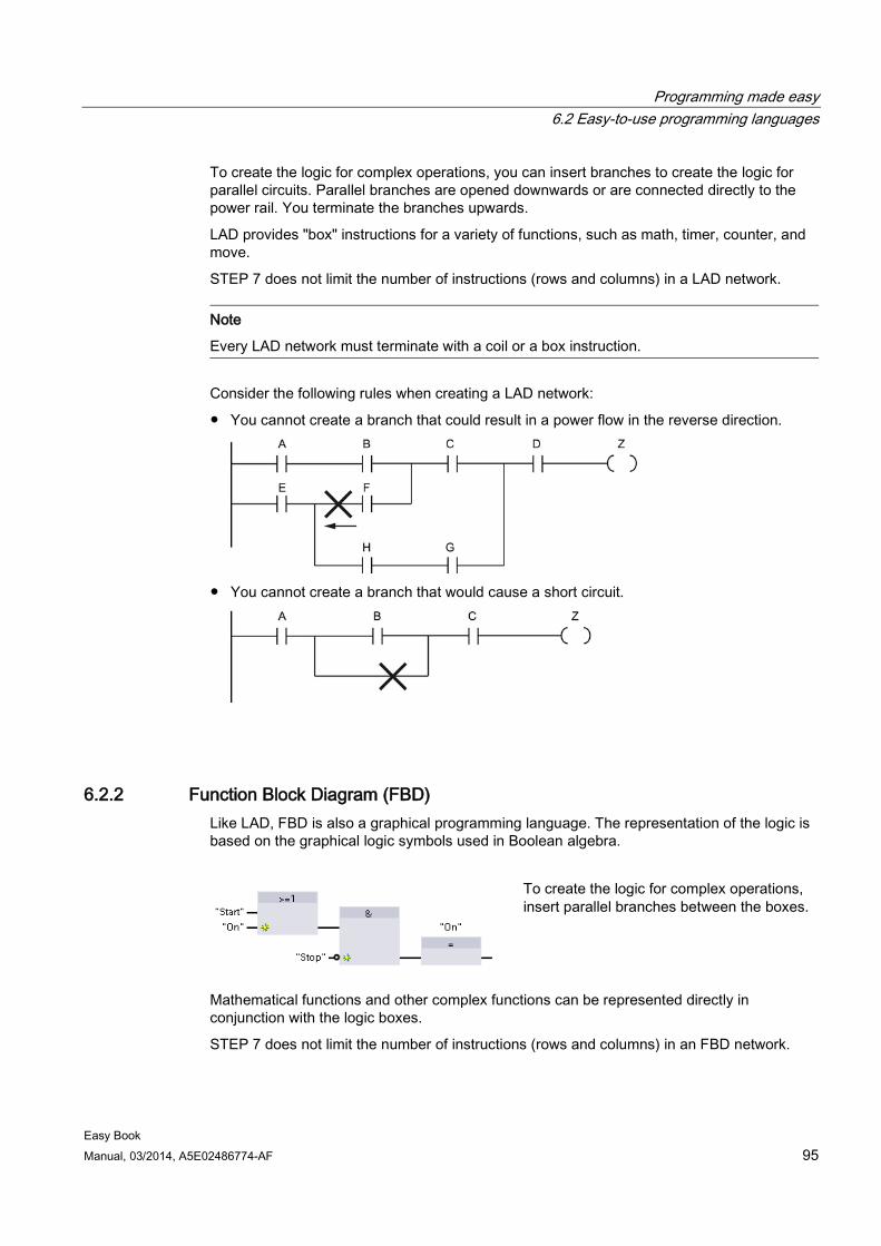
Programming made easy 6.2 Easy-to-use programming languages
Easy Book Manual, 03/2014, A5E02486774-AF 95
To create the logic for complex operations, you can insert branches to create the logic for parallel circuits. Parallel branches are opened downwards or are connected directly to the power rail. You terminate the branches upwards.
LAD provides "box" instructions for a variety of functions, such as math, timer, counter, and move.
STEP 7 does not limit the number of instructions (rows and columns) in a LAD network.
Note
Every LAD network must terminate with a coil or a box instruction.
Consider the following rules when creating a LAD network:
● You cannot create a branch that could result in a power flow in the reverse direction.
● You cannot create a branch that would cause a short circuit.
6.2.2 Function Block Diagram (FBD) Like LAD, FBD is also a graphical programming language. The representation of the logic is based on the graphical logic symbols used in Boolean algebra.
To create the logic for complex operations, insert parallel branches between the boxes.
Mathematical functions and other complex functions can be represented directly in conjunction with the logic boxes.
STEP 7 does not limit the number of instructions (rows and columns) in an FBD network.
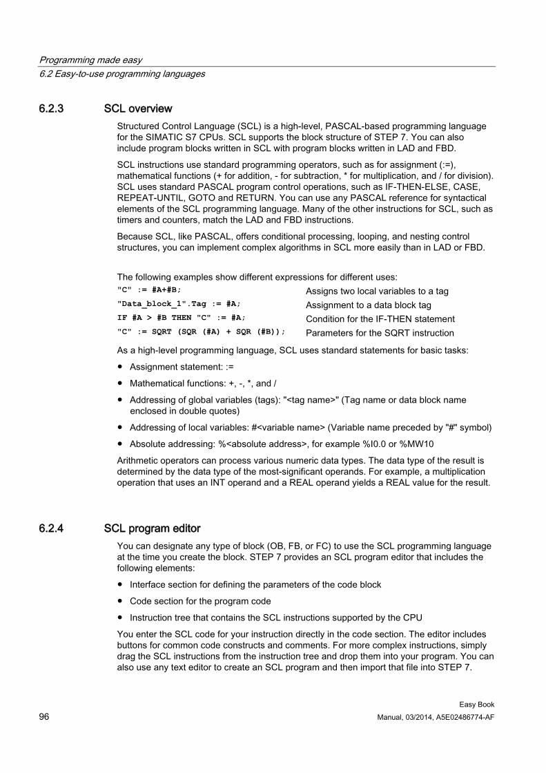
Programming made easy 6.2 Easy-to-use programming languages
Easy Book 96 Manual, 03/2014, A5E02486774-AF
6.2.3 SCL overview Structured Control Language (SCL) is a high-level, PASCAL-based programming language for the SIMATIC S7 CPUs. SCL supports the block structure of STEP 7. You can also include program blocks written in SCL with program blocks written in LAD and FBD.
SCL instructions use standard programming operators, such as for assignment (:=), mathematical functions (+ for addition, - for subtraction, * for multiplication, and / for division). SCL uses standard PASCAL program control operations, such as IF-THEN-ELSE, CASE, REPEAT-UNTIL, GOTO and RETURN. You can use any PASCAL reference for syntactical elements of the SCL programming language. Many of the other instructions for SCL, such as timers and counters, match the LAD and FBD instructions.
Because SCL, like PASCAL, offers conditional processing, looping, and nesting control structures, you can implement complex algorithms in SCL more easily than in LAD or FBD.
The following examples show different expressions for different uses: "C" := #A+#B; Assigns two local variables to a tag "Data_block_1".Tag := #A; Assignment to a data block tag IF #A > #B THEN "C" := #A; Condition for the IF-THEN statement "C" := SQRT (SQR (#A) + SQR (#B)); Parameters for the SQRT instruction
As a high-level programming language, SCL uses standard statements for basic tasks:
● Assignment statement: :=
● Mathematical functions: +, -, *, and /
● Addressing of global variables (tags): "<tag name>" (Tag name or data block name enclosed in double quotes)
● Addressing of local variables: #<variable name> (Variable name preceded by "#" symbol)
● Absolute addressing: %<absolute address>, for example %I0.0 or %MW10
Arithmetic operators can process various numeric data types. The data type of the result is determined by the data type of the most-significant operands. For example, a multiplication operation that uses an INT operand and a REAL operand yields a REAL value for the result.
6.2.4 SCL program editor You can designate any type of block (OB, FB, or FC) to use the SCL programming language at the time you create the block. STEP 7 provides an SCL program editor that includes the following elements:
● Interface section for defining the parameters of the code block
● Code section for the program code
● Instruction tree that contains the SCL instructions supported by the CPU
You enter the SCL code for your instruction directly in the code section. The editor includes buttons for common code constructs and comments. For more complex instructions, simply drag the SCL instructions from the instruction tree and drop them into your program. You can also use any text editor to create an SCL program and then import that file into STEP 7.
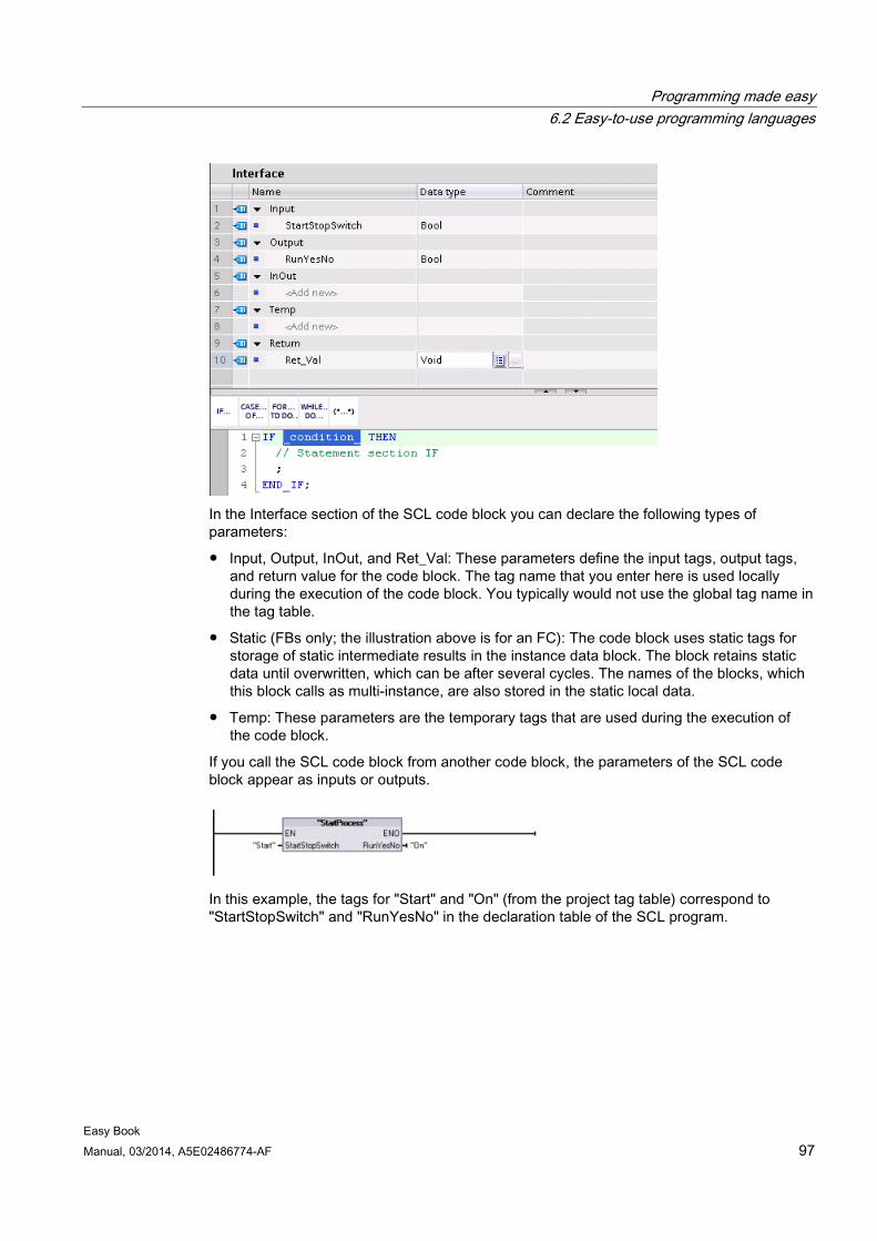
Programming made easy 6.2 Easy-to-use programming languages
Easy Book Manual, 03/2014, A5E02486774-AF 97
In the Interface section of the SCL code block you can declare the following types of parameters:
● Input, Output, InOut, and Ret_Val: These parameters define the input tags, output tags, and return value for the code block. The tag name that you enter here is used locally during the execution of the code block. You typically would not use the global tag name in the tag table.
● Static (FBs only; the illustration above is for an FC): The code block uses static tags for storage of static intermediate results in the instance data block. The block retains static data until overwritten, which can be after several cycles. The names of the blocks, which this block calls as multi-instance, are also stored in the static local data.
● Temp: These parameters are the temporary tags that are used during the execution of the code block.
If you call the SCL code block from another code block, the parameters of the SCL code block appear as inputs or outputs.
In this example, the tags for "Start" and "On" (from the project tag table) correspond to "StartStopSwitch" and "RunYesNo" in the declaration table of the SCL program.
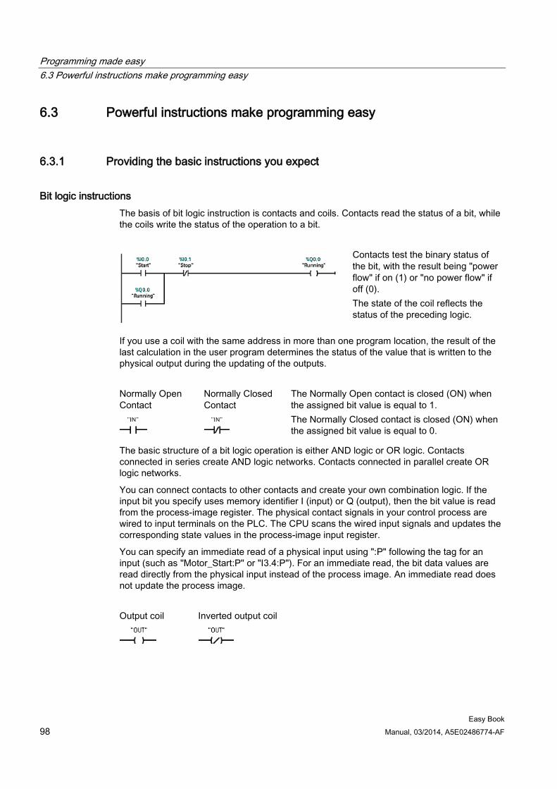
Programming made easy 6.3 Powerful instructions make programming easy
Easy Book 98 Manual, 03/2014, A5E02486774-AF
6.3 Powerful instructions make programming easy
6.3.1 Providing the basic instructions you expect
Bit logic instructions The basis of bit logic instruction is contacts and coils. Contacts read the status of a bit, while the coils write the status of the operation to a bit.
Contacts test the binary status of the bit, with the result being "power flow" if on (1) or "no power flow" if off (0). The state of the coil reflects the status of the preceding logic.
If you use a coil with the same address in more than one program location, the result of the last calculation in the user program determines the status of the value that is written to the physical output during the updating of the outputs.
Normally Open Contact
Normally Closed Contact
The Normally Open contact is closed (ON) when the assigned bit value is equal to 1. The Normally Closed contact is closed (ON) when the assigned bit value is equal to 0.
The basic structure of a bit logic operation is either AND logic or OR logic. Contacts connected in series create AND logic networks. Contacts connected in parallel create OR logic networks.
You can connect contacts to other contacts and create your own combination logic. If the input bit you specify uses memory identifier I (input) or Q (output), then the bit value is read from the process-image register. The physical contact signals in your control process are wired to input terminals on the PLC. The CPU scans the wired input signals and updates the corresponding state values in the process-image input register.
You can specify an immediate read of a physical input using ":P" following the tag for an input (such as "Motor_Start:P" or "I3.4:P"). For an immediate read, the bit data values are read directly from the physical input instead of the process image. An immediate read does not update the process image.
Output coil Inverted output coil
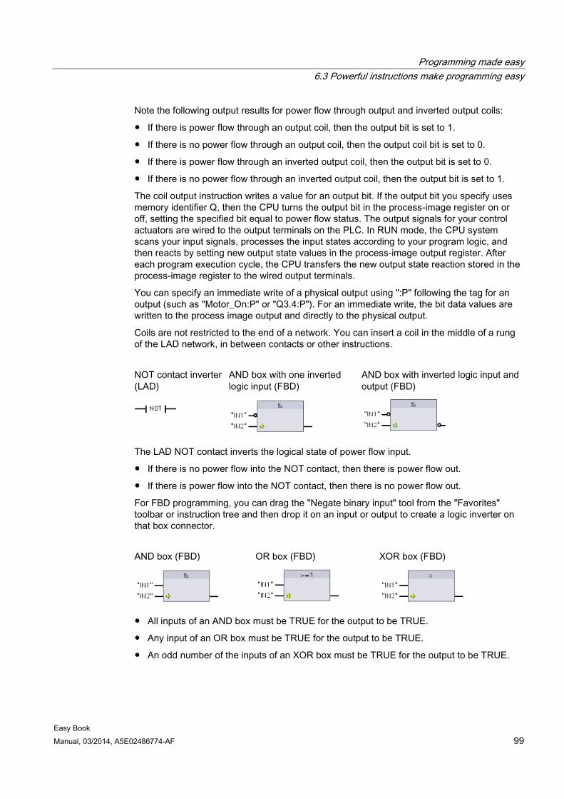
Programming made easy 6.3 Powerful instructions make programming easy
Easy Book Manual, 03/2014, A5E02486774-AF 99
Note the following output results for power flow through output and inverted output coils:
● If there is power flow through an output coil, then the output bit is set to 1.
● If there is no power flow through an output coil, then the output coil bit is set to 0.
● If there is power flow through an inverted output coil, then the output bit is set to 0.
● If there is no power flow through an inverted output coil, then the output bit is set to 1.
The coil output instruction writes a value for an output bit. If the output bit you specify uses memory identifier Q, then the CPU turns the output bit in the process-image register on or off, setting the specified bit equal to power flow status. The output signals for your control actuators are wired to the output terminals on the PLC. In RUN mode, the CPU system scans your input signals, processes the input states according to your program logic, and then reacts by setting new output state values in the process-image output register. After each program execution cycle, the CPU transfers the new output state reaction stored in the process-image register to the wired output terminals.
You can specify an immediate write of a physical output using ":P" following the tag for an output (such as "Motor_On:P" or "Q3.4:P"). For an immediate write, the bit data values are written to the process image output and directly to the physical output.
Coils are not restricted to the end of a network. You can insert a coil in the middle of a rung of the LAD network, in between contacts or other instructions.
NOT contact inverter (LAD)
AND box with one inverted logic input (FBD)
AND box with inverted logic input and output (FBD)
The LAD NOT contact inverts the logical state of power flow input.
● If there is no power flow into the NOT contact, then there is power flow out.
● If there is power flow into the NOT contact, then there is no power flow out.
For FBD programming, you can drag the "Negate binary input" tool from the "Favorites" toolbar or instruction tree and then drop it on an input or output to create a logic inverter on that box connector.
AND box (FBD) OR box (FBD) XOR box (FBD)
● All inputs of an AND box must be TRUE for the output to be TRUE.
● Any input of an OR box must be TRUE for the output to be TRUE.
● An odd number of the inputs of an XOR box must be TRUE for the output to be TRUE.
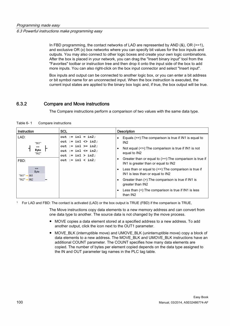
Programming made easy 6.3 Powerful instructions make programming easy
Easy Book 100 Manual, 03/2014, A5E02486774-AF
In FBD programming, the contact networks of LAD are represented by AND (&), OR (>=1), and exclusive OR (x) box networks where you can specify bit values for the box inputs and outputs. You may also connect to other logic boxes and create your own logic combinations. After the box is placed in your network, you can drag the "Insert binary input" tool from the "Favorites" toolbar or instruction tree and then drop it onto the input side of the box to add more inputs. You can also right-click on the box input connector and select "Insert input".
Box inputs and output can be connected to another logic box, or you can enter a bit address or bit symbol name for an unconnected input. When the box instruction is executed, the current input states are applied to the binary box logic and, if true, the box output will be true.
6.3.2 Compare and Move instructions The Compare instructions perform a comparison of two values with the same data type.
Table 6- 1 Compare instructions
Instruction SCL Description LAD:
out := in1 = in2; out := in1 <> in2; out := in1 >= in2; out := in1 <= in2; out := in1 > in2; out := in1 < in2;
• Equals (==):The comparison is true if IN1 is equal to IN2
• Not equal (<>):The comparison is true if IN1 is not equal to IN2
• Greater than or equal to (>=):The comparison is true if IN1 is greater than or equal to IN2
• Less than or equal to (<=):The comparison is true if IN1 is less than or equal to IN2
• Greater than (>):The comparison is true if IN1 is greater than IN2
• Less than (<):The comparison is true if IN1 is less than IN2
FBD:
1 For LAD and FBD: The contact is activated (LAD) or the box output is TRUE (FBD) if the comparison is TRUE,
The Move instructions copy data elements to a new memory address and can convert from one data type to another. The source data is not changed by the move process.
● MOVE copies a data element stored at a specified address to a new address. To add another output, click the icon next to the OUT1 parameter.
● MOVE_BLK (interruptible move) and UMOVE_BLK (uninterruptible move) copy a block of data elements to a new address. The MOVE_BLK and UMOVE_BLK instructions have an additional COUNT parameter. The COUNT specifies how many data elements are copied. The number of bytes per element copied depends on the data type assigned to the IN and OUT parameter tag names in the PLC tag table.
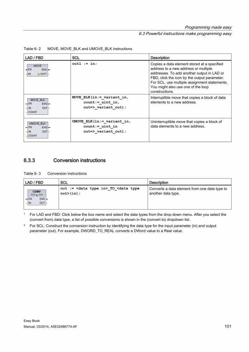
Programming made easy 6.3 Powerful instructions make programming easy
Easy Book Manual, 03/2014, A5E02486774-AF 101
Table 6- 2 MOVE, MOVE_BLK and UMOVE_BLK instructions
LAD / FBD SCL Description
out1 := in; Copies a data element stored at a specified address to a new address or multiple addresses. To add another output in LAD or FBD, click the icon by the output parameter. For SCL, use multiple assignment statements. You might also use one of the loop constructions.
MOVE_BLK(in:=_variant_in, count:=_uint_in, out=>_variant_out);
Interruptible move that copies a block of data elements to a new address.
UMOVE_BLK(in:=_variant_in, count:=_uint_in out=>_variant_out);
Uninterruptible move that copies a block of data elements to a new address.
6.3.3 Conversion instructions
Table 6- 3 Conversion instructions
LAD / FBD SCL Description
out := <data type in>_TO_<data type out>(in);
Converts a data element from one data type to another data type.
1 For LAD and FBD: Click below the box name and select the data types from the drop-down menu. After you select the (convert from) data type, a list of possible conversions is shown in the (convert to) dropdown list.
2 For SCL: Construct the conversion instruction by identifying the data type for the input parameter (in) and output parameter (out). For example, DWORD_TO_REAL converts a DWord value to a Real value.
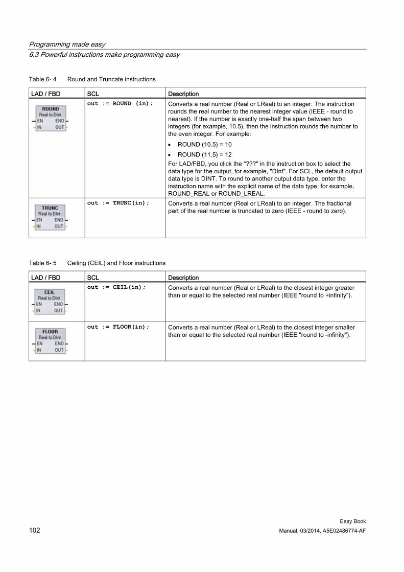
Programming made easy 6.3 Powerful instructions make programming easy
Easy Book 102 Manual, 03/2014, A5E02486774-AF
Table 6- 4 Round and Truncate instructions
LAD / FBD SCL Description
out := ROUND (in); Converts a real number (Real or LReal) to an integer. The instruction rounds the real number to the nearest integer value (IEEE - round to nearest). If the number is exactly one-half the span between two integers (for example, 10.5), then the instruction rounds the number to the even integer. For example: • ROUND (10.5) = 10 • ROUND (11.5) = 12 For LAD/FBD, you click the "???" in the instruction box to select the data type for the output, for example, "DInt". For SCL, the default output data type is DINT. To round to another output data type, enter the instruction name with the explicit name of the data type, for example, ROUND_REAL or ROUND_LREAL.
out := TRUNC(in); Converts a real number (Real or LReal) to an integer. The fractional part of the real number is truncated to zero (IEEE - round to zero).
Table 6- 5 Ceiling (CEIL) and Floor instructions
LAD / FBD SCL Description
out := CEIL(in); Converts a real number (Real or LReal) to the closest integer greater than or equal to the selected real number (IEEE "round to +infinity").
out := FLOOR(in); Converts a real number (Real or LReal) to the closest integer smaller than or equal to the selected real number (IEEE "round to -infinity").
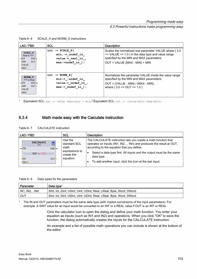
Programming made easy 6.3 Powerful instructions make programming easy
Easy Book Manual, 03/2014, A5E02486774-AF 103
Table 6- 6 SCALE_X and NORM_X instructions
LAD / FBD SCL Description
out := SCALE_X( min,:=_undef_in_ value:=_real_in_, max:=undef_in_);
Scales the normalized real parameter VALUE where ( 0.0 <= VALUE <= 1.0 ) in the data type and value range specified by the MIN and MAX parameters: OUT = VALUE (MAX - MIN) + MIN
out := NORM_X( min:=_,undef_in_ value:=_undef_in_, max:=_undef_in_);
Normalizes the parameter VALUE inside the value range specified by the MIN and MAX parameters: OUT = (VALUE - MIN) / (MAX - MIN), where ( 0.0 <= OUT <= 1.0 )
1 Equivalent SCL: out := value (max-min) + min;2 Equivalent SCL: out := (value-min)/(max-min);
6.3.4 Math made easy with the Calculate instruction
Table 6- 7 CALCULATE instruction
LAD / FBD SCL Description
Use the standard SCL math expressions to create the equation.
The CALCULATE instruction lets you create a math function that operates on inputs (IN1, IN2, .. INn) and produces the result at OUT, according to the equation that you define. • Select a data type first. All inputs and the output must be the same
data type. • To add another input, click the icon at the last input.
Table 6- 8 Data types for the parameters
Parameter Data type1 IN1, IN2, ..INn SInt, Int, DInt, USInt, UInt, UDInt, Real, LReal, Byte, Word, DWord OUT SInt, Int, DInt, USInt, UInt, UDInt, Real, LReal, Byte, Word, DWord 1 The IN and OUT parameters must be the same data type (with implicit conversions of the input parameters). For
example: A SINT value for an input would be converted to an INT or a REAL value if OUT is an INT or REAL
Click the calculator icon to open the dialog and define your math function. You enter your equation as inputs (such as IN1 and IN2) and operations. When you click "OK" to save the function, the dialog automatically creates the inputs for the CALCULATE instruction.
An example and a list of possible math operations you can include is shown at the bottom of the editor.
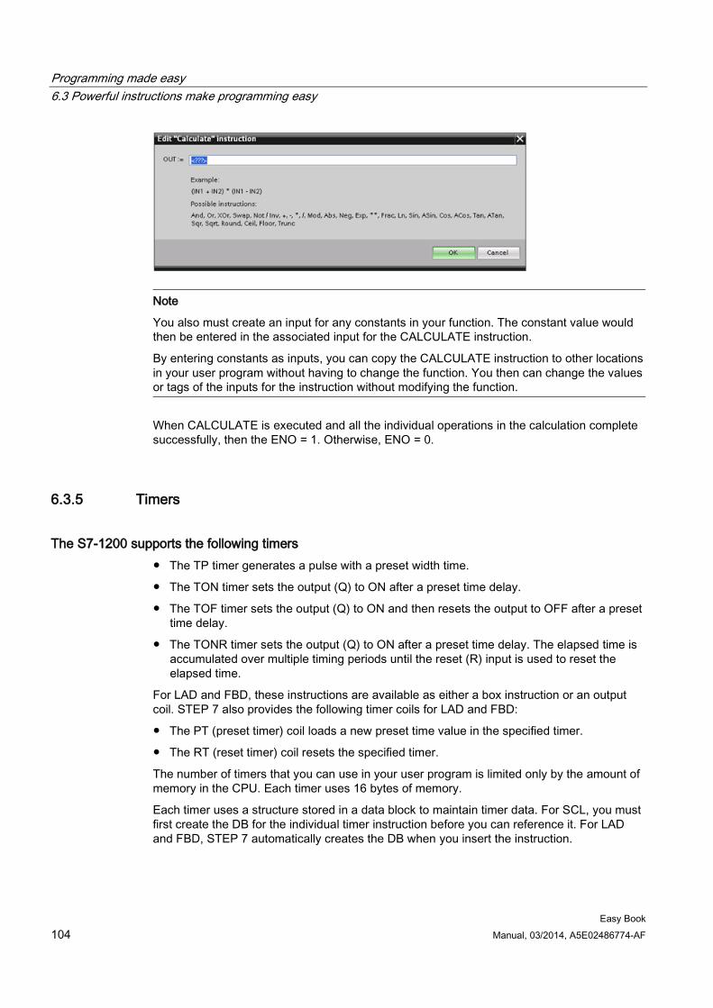
Programming made easy 6.3 Powerful instructions make programming easy
Easy Book 104 Manual, 03/2014, A5E02486774-AF
Note
You also must create an input for any constants in your function. The constant value would then be entered in the associated input for the CALCULATE instruction.
By entering constants as inputs, you can copy the CALCULATE instruction to other locations in your user program without having to change the function. You then can change the values or tags of the inputs for the instruction without modifying the function.
When CALCULATE is executed and all the individual operations in the calculation complete successfully, then the ENO = 1. Otherwise, ENO = 0.
6.3.5 Timers
The S7-1200 supports the following timers ● The TP timer generates a pulse with a preset width time.
● The TON timer sets the output (Q) to ON after a preset time delay.
● The TOF timer sets the output (Q) to ON and then resets the output to OFF after a preset time delay.
● The TONR timer sets the output (Q) to ON after a preset time delay. The elapsed time is accumulated over multiple timing periods until the reset (R) input is used to reset the elapsed time.
For LAD and FBD, these instructions are available as either a box instruction or an output coil. STEP 7 also provides the following timer coils for LAD and FBD:
● The PT (preset timer) coil loads a new preset time value in the specified timer.
● The RT (reset timer) coil resets the specified timer.
The number of timers that you can use in your user program is limited only by the amount of memory in the CPU. Each timer uses 16 bytes of memory.
Each timer uses a structure stored in a data block to maintain timer data. For SCL, you must first create the DB for the individual timer instruction before you can reference it. For LAD and FBD, STEP 7 automatically creates the DB when you insert the instruction.
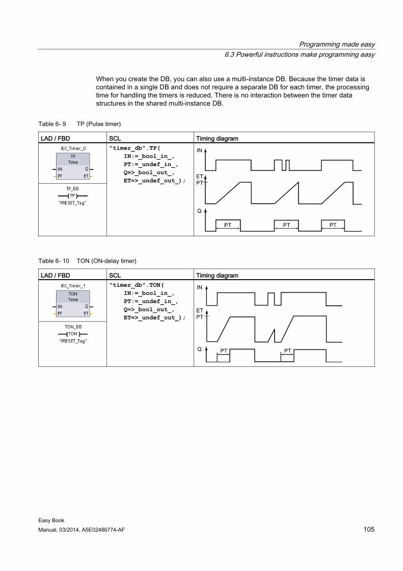
Programming made easy 6.3 Powerful instructions make programming easy
Easy Book Manual, 03/2014, A5E02486774-AF 105
When you create the DB, you can also use a multi-instance DB. Because the timer data is contained in a single DB and does not require a separate DB for each timer, the processing time for handling the timers is reduced. There is no interaction between the timer data structures in the shared multi-instance DB.
Table 6- 9 TP (Pulse timer)
LAD / FBD SCL Timing diagram
"timer_db".TP( IN:=_bool_in_, PT:=_undef_in_, Q=>_bool_out_, ET=>_undef_out_);
Table 6- 10 TON (ON-delay timer)
LAD / FBD SCL Timing diagram
"timer_db".TON( IN:=_bool_in_, PT:=_undef_in_, Q=>_bool_out_, ET=>_undef_out_);
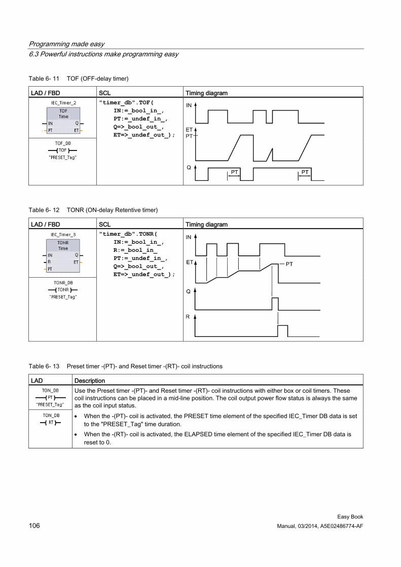
Programming made easy 6.3 Powerful instructions make programming easy
Easy Book 106 Manual, 03/2014, A5E02486774-AF
Table 6- 11 TOF (OFF-delay timer)
LAD / FBD SCL Timing diagram
"timer_db".TOF( IN:=_bool_in_, PT:=_undef_in_, Q=>_bool_out_, ET=>_undef_out_);
Table 6- 12 TONR (ON-delay Retentive timer)
LAD / FBD SCL Timing diagram
"timer_db".TONR( IN:=_bool_in_, R:=_bool_in_ PT:=_undef_in_, Q=>_bool_out_, ET=>_undef_out_);
Table 6- 13 Preset timer -(PT)- and Reset timer -(RT)- coil instructions
LAD Description
Use the Preset timer -(PT)- and Reset timer -(RT)- coil instructions with either box or coil timers. These coil instructions can be placed in a mid-line position. The coil output power flow status is always the same as the coil input status. • When the -(PT)- coil is activated, the PRESET time element of the specified IEC_Timer DB data is set
to the "PRESET_Tag" time duration. • When the -(RT)- coil is activated, the ELAPSED time element of the specified IEC_Timer DB data is
reset to 0.
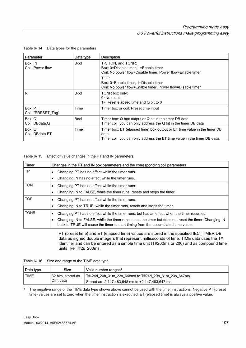
Programming made easy 6.3 Powerful instructions make programming easy
Easy Book Manual, 03/2014, A5E02486774-AF 107
Table 6- 14 Data types for the parameters
Parameter Data type Description Box: IN Coil: Power flow
Bool TP, TON, and TONR: Box: 0=Disable timer, 1=Enable timer Coil: No power flow=Disable timer, Power flow=Enable timer TOF: Box: 0=Enable timer, 1=Disable timer Coil: No power flow=Enable timer, Power flow=Disable timer
R Bool TONR box only: 0=No reset 1= Reset elapsed time and Q bit to 0
Box: PT Coil: "PRESET_Tag"
Time Timer box or coil: Preset time input
Box: Q Coil: DBdata.Q
Bool Timer box: Q box output or Q bit in the timer DB data Timer coil: you can only address the Q bit in the timer DB data
Box: ET Coil: DBdata.ET
Time Timer box: ET (elapsed time) box output or ET time value in the timer DB data Timer coil: you can only address the ET time value in the timer DB data.
Table 6- 15 Effect of value changes in the PT and IN parameters
Timer Changes in the PT and IN box parameters and the corresponding coil parameters TP • Changing PT has no effect while the timer runs.
• Changing IN has no effect while the timer runs.
TON • Changing PT has no effect while the timer runs. • Changing IN to FALSE, while the timer runs, resets and stops the timer.
TOF • Changing PT has no effect while the timer runs. • Changing IN to TRUE, while the timer runs, resets and stops the timer.
TONR • Changing PT has no effect while the timer runs, but has an effect when the timer resumes. • Changing IN to FALSE, while the timer runs, stops the timer but does not reset the timer. Changing IN
back to TRUE will cause the timer to start timing from the accumulated time value.
PT (preset time) and ET (elapsed time) values are stored in the specified IEC_TIMER DB data as signed double integers that represent milliseconds of time. TIME data uses the T# identifier and can be entered as a simple time unit (T#200ms or 200) and as compound time units like T#2s_200ms.
Table 6- 16 Size and range of the TIME data type
Data type Size Valid number ranges1 TIME 32 bits, stored as
DInt data T#-24d_20h_31m_23s_648ms to T#24d_20h_31m_23s_647ms Stored as -2,147,483,648 ms to +2,147,483,647 ms
1 The negative range of the TIME data type shown above cannot be used with the timer instructions. Negative PT (preset time) values are set to zero when the timer instruction is executed. ET (elapsed time) is always a positive value.
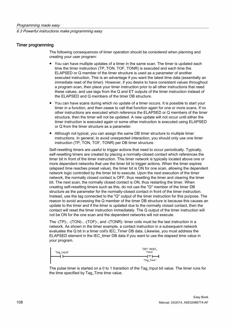
Programming made easy 6.3 Powerful instructions make programming easy
Easy Book 108 Manual, 03/2014, A5E02486774-AF
Timer programming The following consequences of timer operation should be considered when planning and creating your user program:
● You can have multiple updates of a timer in the same scan. The timer is updated each time the timer instruction (TP, TON, TOF, TONR) is executed and each time the ELAPSED or Q member of the timer structure is used as a parameter of another executed instruction. This is an advantage if you want the latest time data (essentially an immediate read of the timer). However, if you desire to have consistent values throughout a program scan, then place your timer instruction prior to all other instructions that need these values, and use tags from the Q and ET outputs of the timer instruction instead of the ELAPSED and Q members of the timer DB structure.
● You can have scans during which no update of a timer occurs. It is possible to start your timer in a function, and then cease to call that function again for one or more scans. If no other instructions are executed which reference the ELAPSED or Q members of the timer structure, then the timer will not be updated. A new update will not occur until either the timer instruction is executed again or some other instruction is executed using ELAPSED or Q from the timer structure as a parameter.
● Although not typical, you can assign the same DB timer structure to multiple timer instructions. In general, to avoid unexpected interaction, you should only use one timer instruction (TP, TON, TOF, TONR) per DB timer structure.
Self-resetting timers are useful to trigger actions that need to occur periodically. Typically, self-resetting timers are created by placing a normally-closed contact which references the timer bit in front of the timer instruction. This timer network is typically located above one or more dependent networks that use the timer bit to trigger actions. When the timer expires (elapsed time reaches preset value), the timer bit is ON for one scan, allowing the dependent network logic controlled by the timer bit to execute. Upon the next execution of the timer network, the normally closed contact is OFF, thus resetting the timer and clearing the timer bit. The next scan, the normally closed contact is ON, thus restarting the timer. When creating self-resetting timers such as this, do not use the "Q" member of the timer DB structure as the parameter for the normally-closed contact in front of the timer instruction. Instead, use the tag connected to the "Q" output of the timer instruction for this purpose. The reason to avoid accessing the Q member of the timer DB structure is because this causes an update to the timer and if the timer is updated due to the normally closed contact, then the contact will reset the timer instruction immediately. The Q output of the timer instruction will not be ON for the one scan and the dependent networks will not execute.
The -(TP)-, -(TON)-, -(TOF)-, and -(TONR)- timer coils must be the last instruction in a network. As shown in the timer example, a contact instruction in a subsequent network evaluates the Q bit in a timer coil's IEC_Timer DB data. Likewise, you must address the ELAPSED element in the IEC_timer DB data if you want to use the elapsed time value in your program.
The pulse timer is started on a 0 to 1 transition of the Tag_Input bit value. The timer runs for the time specified by Tag_Time time value.
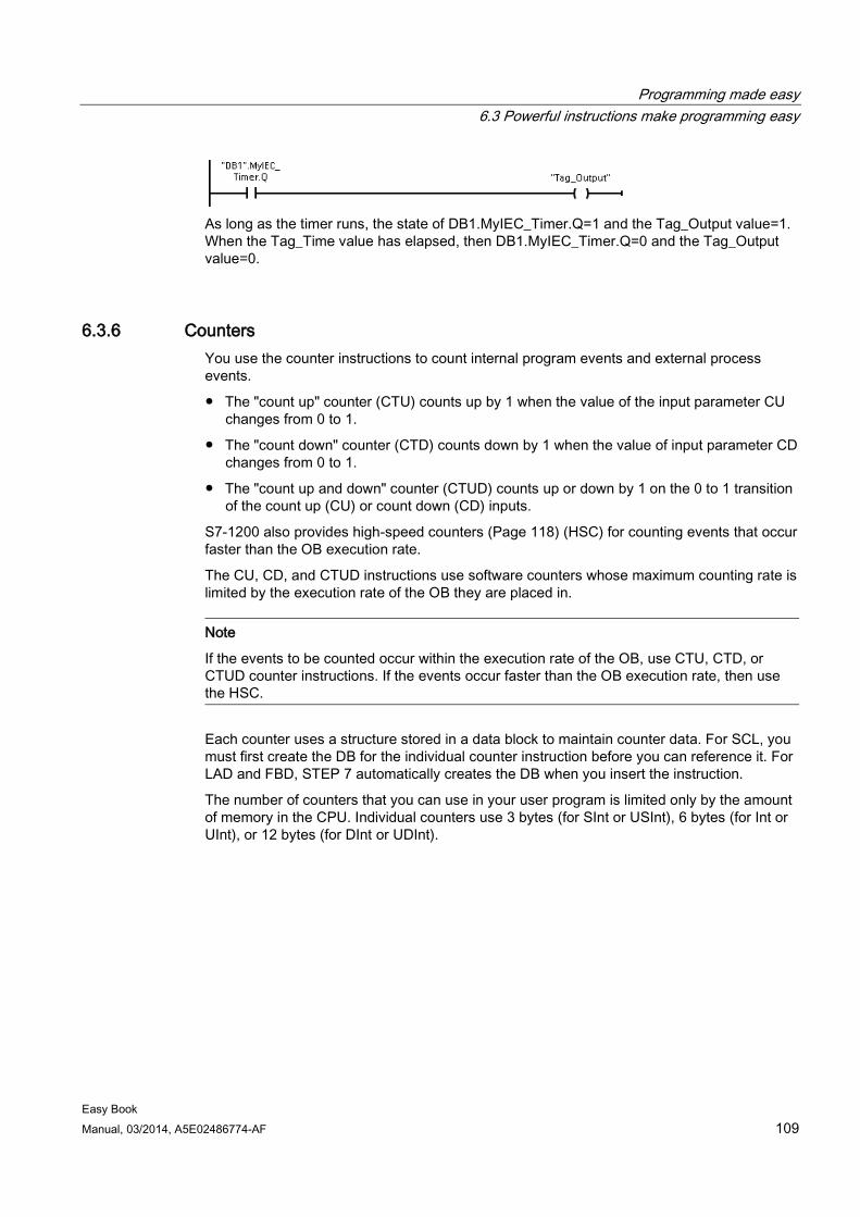
Programming made easy 6.3 Powerful instructions make programming easy
Easy Book Manual, 03/2014, A5E02486774-AF 109
As long as the timer runs, the state of DB1.MyIEC_Timer.Q=1 and the Tag_Output value=1. When the Tag_Time value has elapsed, then DB1.MyIEC_Timer.Q=0 and the Tag_Output value=0.
6.3.6 Counters You use the counter instructions to count internal program events and external process events.
● The "count up" counter (CTU) counts up by 1 when the value of the input parameter CU changes from 0 to 1.
● The "count down" counter (CTD) counts down by 1 when the value of input parameter CD changes from 0 to 1.
● The "count up and down" counter (CTUD) counts up or down by 1 on the 0 to 1 transition of the count up (CU) or count down (CD) inputs.
S7-1200 also provides high-speed counters (Page 118) (HSC) for counting events that occur faster than the OB execution rate.
The CU, CD, and CTUD instructions use software counters whose maximum counting rate is limited by the execution rate of the OB they are placed in.
Note
If the events to be counted occur within the execution rate of the OB, use CTU, CTD, or CTUD counter instructions. If the events occur faster than the OB execution rate, then use the HSC.
Each counter uses a structure stored in a data block to maintain counter data. For SCL, you must first create the DB for the individual counter instruction before you can reference it. For LAD and FBD, STEP 7 automatically creates the DB when you insert the instruction.
The number of counters that you can use in your user program is limited only by the amount of memory in the CPU. Individual counters use 3 bytes (for SInt or USInt), 6 bytes (for Int or UInt), or 12 bytes (for DInt or UDInt).
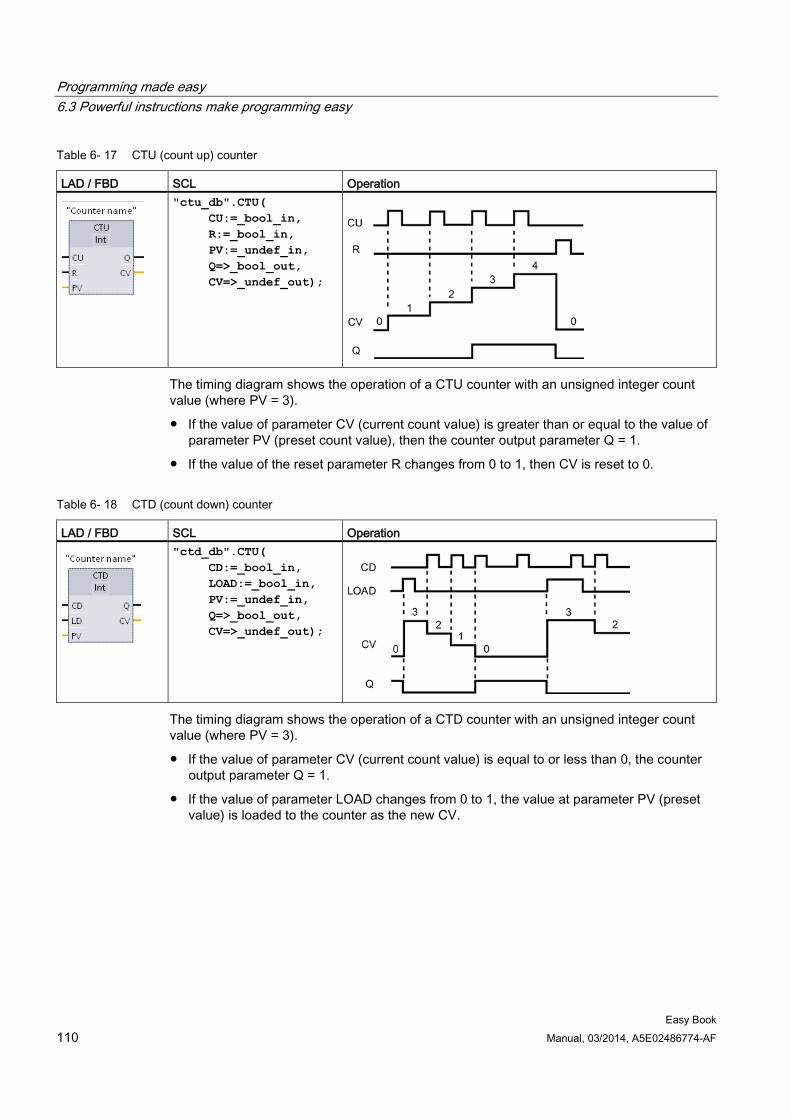
Programming made easy 6.3 Powerful instructions make programming easy
Easy Book 110 Manual, 03/2014, A5E02486774-AF
Table 6- 17 CTU (count up) counter
LAD / FBD SCL Operation
"ctu_db".CTU( CU:=_bool_in, R:=_bool_in, PV:=_undef_in, Q=>_bool_out, CV=>_undef_out);
The timing diagram shows the operation of a CTU counter with an unsigned integer count value (where PV = 3).
● If the value of parameter CV (current count value) is greater than or equal to the value of parameter PV (preset count value), then the counter output parameter Q = 1.
● If the value of the reset parameter R changes from 0 to 1, then CV is reset to 0.
Table 6- 18 CTD (count down) counter
LAD / FBD SCL Operation
"ctd_db".CTU( CD:=_bool_in, LOAD:=_bool_in, PV:=_undef_in, Q=>_bool_out, CV=>_undef_out);
The timing diagram shows the operation of a CTD counter with an unsigned integer count value (where PV = 3).
● If the value of parameter CV (current count value) is equal to or less than 0, the counter output parameter Q = 1.
● If the value of parameter LOAD changes from 0 to 1, the value at parameter PV (preset value) is loaded to the counter as the new CV.
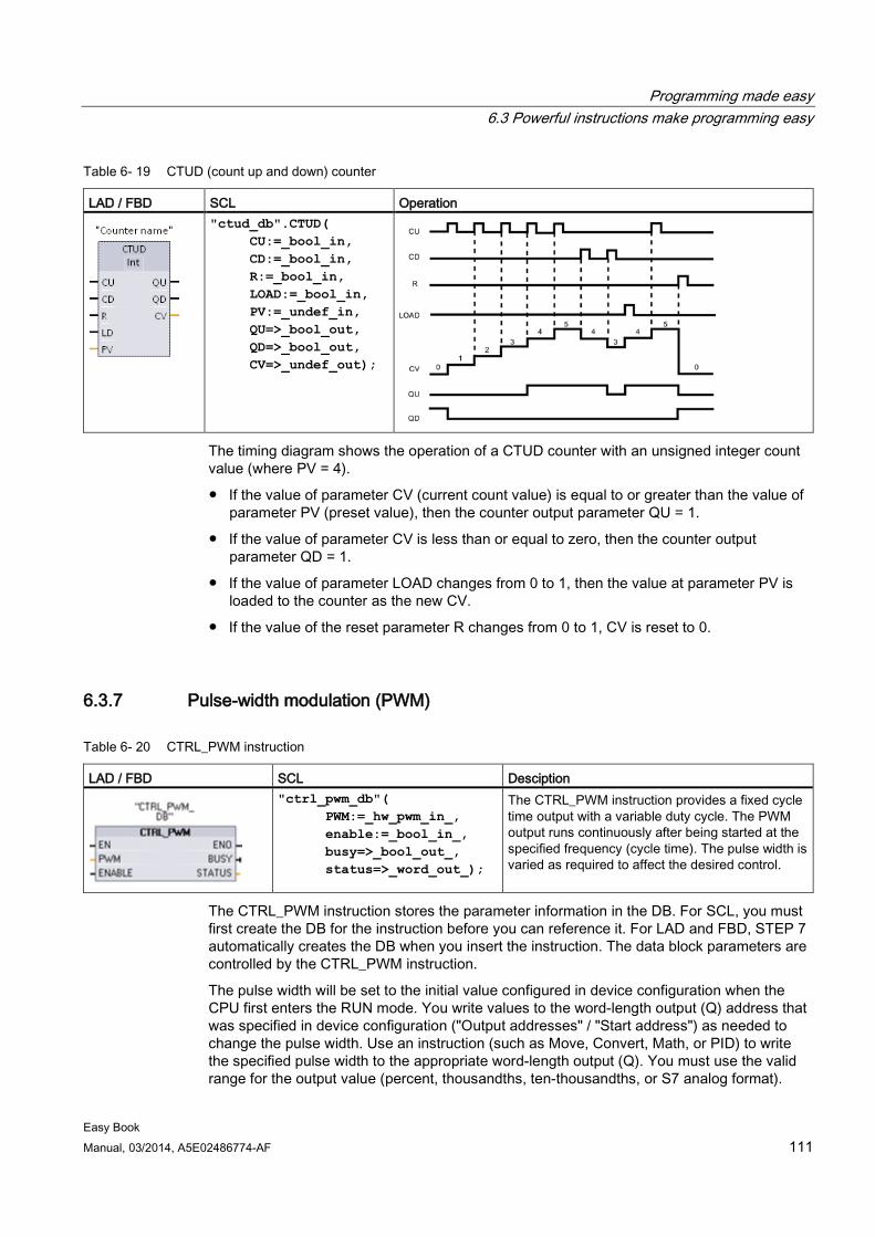
Programming made easy 6.3 Powerful instructions make programming easy
Easy Book Manual, 03/2014, A5E02486774-AF 111
Table 6- 19 CTUD (count up and down) counter
LAD / FBD SCL Operation
"ctud_db".CTUD( CU:=_bool_in, CD:=_bool_in, R:=_bool_in, LOAD:=_bool_in, PV:=_undef_in, QU=>_bool_out, QD=>_bool_out, CV=>_undef_out);
The timing diagram shows the operation of a CTUD counter with an unsigned integer count value (where PV = 4).
● If the value of parameter CV (current count value) is equal to or greater than the value of parameter PV (preset value), then the counter output parameter QU = 1.
● If the value of parameter CV is less than or equal to zero, then the counter output parameter QD = 1.
● If the value of parameter LOAD changes from 0 to 1, then the value at parameter PV is loaded to the counter as the new CV.
● If the value of the reset parameter R changes from 0 to 1, CV is reset to 0.
6.3.7 Pulse-width modulation (PWM)
Table 6- 20 CTRL_PWM instruction
LAD / FBD SCL Desciption
"ctrl_pwm_db"( PWM:=_hw_pwm_in_, enable:=_bool_in_, busy=>_bool_out_, status=>_word_out_);
The CTRL_PWM instruction provides a fixed cycle time output with a variable duty cycle. The PWM output runs continuously after being started at the specified frequency (cycle time). The pulse width is varied as required to affect the desired control.
The CTRL_PWM instruction stores the parameter information in the DB. For SCL, you must first create the DB for the instruction before you can reference it. For LAD and FBD, STEP 7 automatically creates the DB when you insert the instruction. The data block parameters are controlled by the CTRL_PWM instruction.
The pulse width will be set to the initial value configured in device configuration when the CPU first enters the RUN mode. You write values to the word-length output (Q) address that was specified in device configuration ("Output addresses" / "Start address") as needed to change the pulse width. Use an instruction (such as Move, Convert, Math, or PID) to write the specified pulse width to the appropriate word-length output (Q). You must use the valid range for the output value (percent, thousandths, ten-thousandths, or S7 analog format).
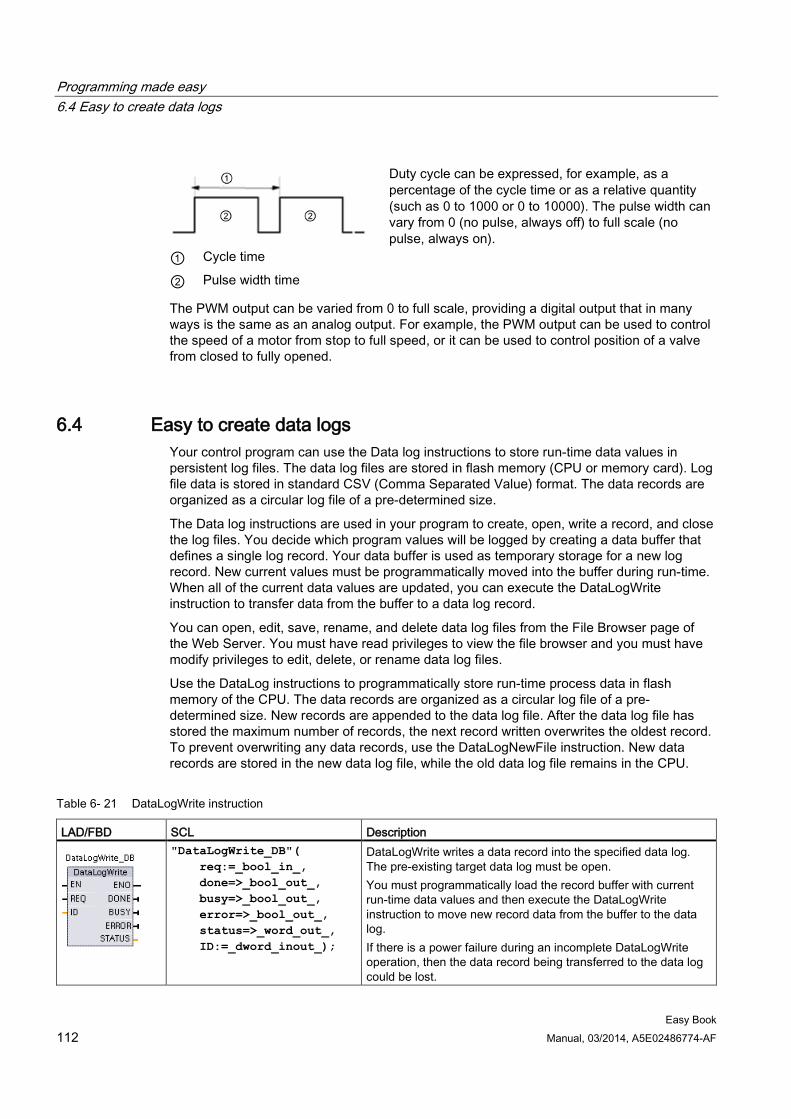
Programming made easy 6.4 Easy to create data logs
Easy Book 112 Manual, 03/2014, A5E02486774-AF
Duty cycle can be expressed, for example, as a percentage of the cycle time or as a relative quantity (such as 0 to 1000 or 0 to 10000). The pulse width can vary from 0 (no pulse, always off) to full scale (no pulse, always on).
① Cycle time
② Pulse width time
The PWM output can be varied from 0 to full scale, providing a digital output that in many ways is the same as an analog output. For example, the PWM output can be used to control the speed of a motor from stop to full speed, or it can be used to control position of a valve from closed to fully opened.
6.4 Easy to create data logs Your control program can use the Data log instructions to store run-time data values in persistent log files. The data log files are stored in flash memory (CPU or memory card). Log file data is stored in standard CSV (Comma Separated Value) format. The data records are organized as a circular log file of a pre-determined size.
The Data log instructions are used in your program to create, open, write a record, and close the log files. You decide which program values will be logged by creating a data buffer that defines a single log record. Your data buffer is used as temporary storage for a new log record. New current values must be programmatically moved into the buffer during run-time. When all of the current data values are updated, you can execute the DataLogWrite instruction to transfer data from the buffer to a data log record.
You can open, edit, save, rename, and delete data log files from the File Browser page of the Web Server. You must have read privileges to view the file browser and you must have modify privileges to edit, delete, or rename data log files.
Use the DataLog instructions to programmatically store run-time process data in flash memory of the CPU. The data records are organized as a circular log file of a pre-determined size. New records are appended to the data log file. After the data log file has stored the maximum number of records, the next record written overwrites the oldest record. To prevent overwriting any data records, use the DataLogNewFile instruction. New data records are stored in the new data log file, while the old data log file remains in the CPU.
Table 6- 21 DataLogWrite instruction
LAD/FBD SCL Description
"DataLogWrite_DB"( req:=_bool_in_, done=>_bool_out_, busy=>_bool_out_, error=>_bool_out_, status=>_word_out_, ID:=_dword_inout_);
DataLogWrite writes a data record into the specified data log. The pre-existing target data log must be open. You must programmatically load the record buffer with current run-time data values and then execute the DataLogWrite instruction to move new record data from the buffer to the data log. If there is a power failure during an incomplete DataLogWrite operation, then the data record being transferred to the data log could be lost.
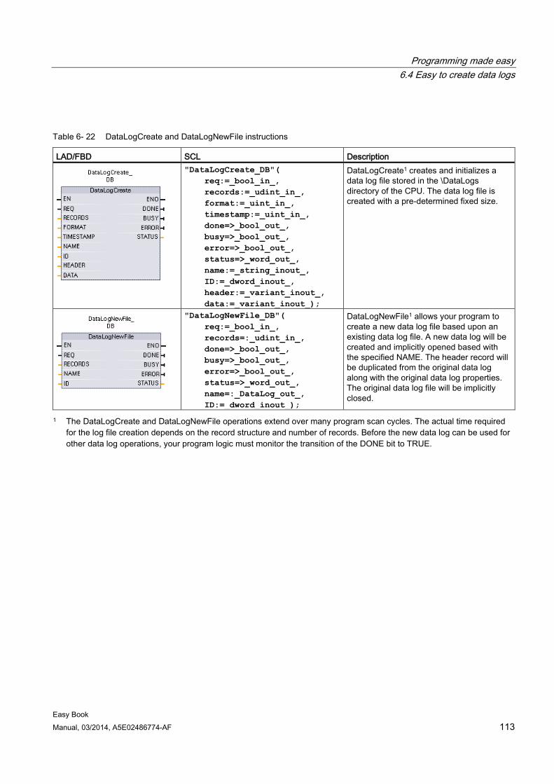
Programming made easy 6.4 Easy to create data logs
Easy Book Manual, 03/2014, A5E02486774-AF 113
Table 6- 22 DataLogCreate and DataLogNewFile instructions
LAD/FBD SCL Description
"DataLogCreate_DB"( req:=_bool_in_, records:=_udint_in_, format:=_uint_in_, timestamp:=_uint_in_, done=>_bool_out_, busy=>_bool_out_, error=>_bool_out_, status=>_word_out_, name:=_string_inout_, ID:=_dword_inout_, header:=_variant_inout_, data:=_variant_inout_);
DataLogCreate1 creates and initializes a data log file stored in the \DataLogs directory of the CPU. The data log file is created with a pre-determined fixed size.
"DataLogNewFile_DB"( req:=_bool_in_, records=:_udint_in_, done=>_bool_out_, busy=>_bool_out_, error=>_bool_out_, status=>_word_out_, name=:_DataLog_out_, ID:=_dword_inout_);
DataLogNewFile1 allows your program to create a new data log file based upon an existing data log file. A new data log will be created and implicitly opened based with the specified NAME. The header record will be duplicated from the original data log along with the original data log properties. The original data log file will be implicitly closed.
1 The DataLogCreate and DataLogNewFile operations extend over many program scan cycles. The actual time required for the log file creation depends on the record structure and number of records. Before the new data log can be used for other data log operations, your program logic must monitor the transition of the DONE bit to TRUE.
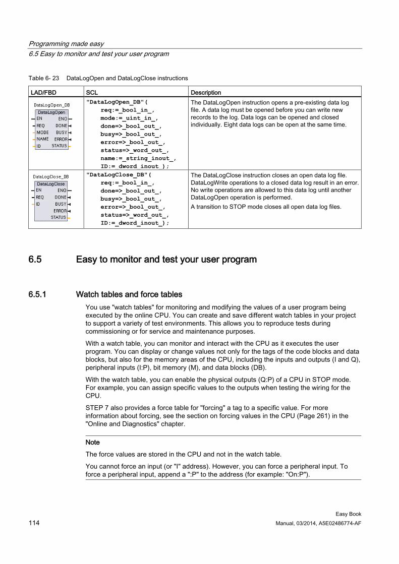
Programming made easy 6.5 Easy to monitor and test your user program
Easy Book 114 Manual, 03/2014, A5E02486774-AF
Table 6- 23 DataLogOpen and DataLogClose instructions
LAD/FBD SCL Description
"DataLogOpen_DB"( req:=_bool_in_, mode:=_uint_in_, done=>_bool_out_, busy=>_bool_out_, error=>_bool_out_, status=>_word_out_, name:=_string_inout_, ID:=_dword_inout_);
The DataLogOpen instruction opens a pre-existing data log file. A data log must be opened before you can write new records to the log. Data logs can be opened and closed individually. Eight data logs can be open at the same time.
"DataLogClose_DB"( req:=_bool_in_, done=>_bool_out_, busy=>_bool_out_, error=>_bool_out_, status=>_word_out_, ID:=_dword_inout_);
The DataLogClose instruction closes an open data log file. DataLogWrite operations to a closed data log result in an error. No write operations are allowed to this data log until another DataLogOpen operation is performed. A transition to STOP mode closes all open data log files.
6.5 Easy to monitor and test your user program
6.5.1 Watch tables and force tables You use "watch tables" for monitoring and modifying the values of a user program being executed by the online CPU. You can create and save different watch tables in your project to support a variety of test environments. This allows you to reproduce tests during commissioning or for service and maintenance purposes.
With a watch table, you can monitor and interact with the CPU as it executes the user program. You can display or change values not only for the tags of the code blocks and data blocks, but also for the memory areas of the CPU, including the inputs and outputs (I and Q), peripheral inputs (I:P), bit memory (M), and data blocks (DB).
With the watch table, you can enable the physical outputs (Q:P) of a CPU in STOP mode. For example, you can assign specific values to the outputs when testing the wiring for the CPU.
STEP 7 also provides a force table for "forcing" a tag to a specific value. For more information about forcing, see the section on forcing values in the CPU (Page 261) in the "Online and Diagnostics" chapter.
Note
The force values are stored in the CPU and not in the watch table.
You cannot force an input (or "I" address). However, you can force a peripheral input. To force a peripheral input, append a ":P" to the address (for example: "On:P").
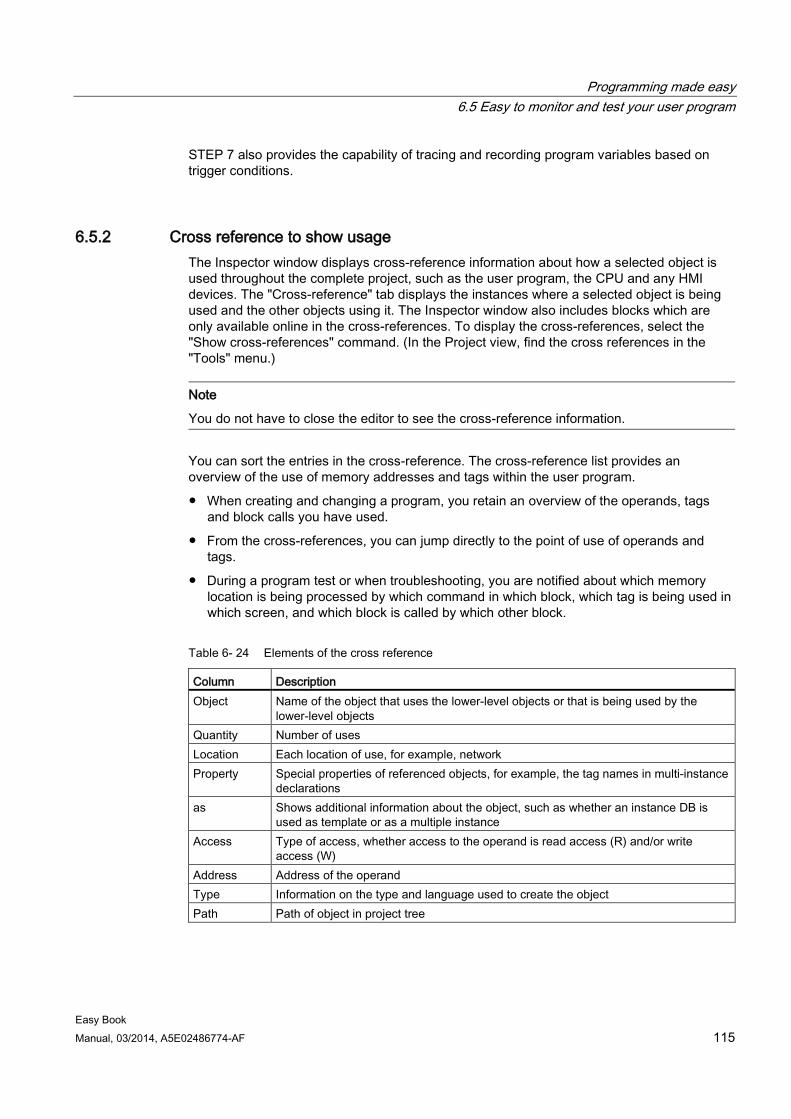
Programming made easy 6.5 Easy to monitor and test your user program
Easy Book Manual, 03/2014, A5E02486774-AF 115
STEP 7 also provides the capability of tracing and recording program variables based on trigger conditions.
6.5.2 Cross reference to show usage The Inspector window displays cross-reference information about how a selected object is used throughout the complete project, such as the user program, the CPU and any HMI devices. The "Cross-reference" tab displays the instances where a selected object is being used and the other objects using it. The Inspector window also includes blocks which are only available online in the cross-references. To display the cross-references, select the "Show cross-references" command. (In the Project view, find the cross references in the "Tools" menu.)
Note
You do not have to close the editor to see the cross-reference information.
You can sort the entries in the cross-reference. The cross-reference list provides an overview of the use of memory addresses and tags within the user program.
● When creating and changing a program, you retain an overview of the operands, tags and block calls you have used.
● From the cross-references, you can jump directly to the point of use of operands and tags.
● During a program test or when troubleshooting, you are notified about which memory location is being processed by which command in which block, which tag is being used in which screen, and which block is called by which other block.
Table 6- 24 Elements of the cross reference
Column Description Object Name of the object that uses the lower-level objects or that is being used by the
lower-level objects Quantity Number of uses Location Each location of use, for example, network Property Special properties of referenced objects, for example, the tag names in multi-instance
declarations as Shows additional information about the object, such as whether an instance DB is
used as template or as a multiple instance Access Type of access, whether access to the operand is read access (R) and/or write
access (W) Address Address of the operand Type Information on the type and language used to create the object Path Path of object in project tree
Programming made easy 6.5 Easy to monitor and test your user program
Easy Book 116 Manual, 03/2014, A5E02486774-AF
6.5.3 Call structure to examine the calling hierarchy The call structure describes the call hierarchy of the block within your user program. It provides an overview of the blocks used, calls to other blocks, the relationships between blocks, the data requirements for each block, and the status of the blocks. You can open the program editor and edit blocks from the call structure.
Displaying the call structure provides you with a list of the blocks used in the user program. STEP 7 highlights the first level of the call structure and displays any blocks that are not called by any other block in the program. The first level of the call structure displays the OBs and any FCs, FBs, and DBs that are not called by an OB. If a code block calls another block, the called block is shown as an indentation under the calling block. The call structure only displays those blocks that are called by a code block.
You can selectively display only the blocks causing conflicts within the call structure. The following conditions cause conflicts:
● Blocks that execute any calls with older or newer code time stamps
● Blocks that call a block with modified interface
● Blocks that use a tag with modified address and/or data type
● Blocks that are called neither directly nor indirectly by an OB
● Blocks that call a non-existent or missing block
You can group several block calls and data blocks as a group. You use a drop-down list to see the links to the various call locations.
You can also perform a consistency check to show time stamp conflicts. Changing the time stamp of a block during or after the program is generated can lead to time stamp conflicts, which in turn cause inconsistencies among the blocks that are calling and being called.
● Most time stamp and interface conflicts can be corrected by recompiling the code blocks.
● If compilation fails to clear up inconsistencies, use the link in the "Details" column to go to the source of the problem in the program editor. You can then manually eliminate any inconsistencies.
● Any blocks marked in red must be recompiled.
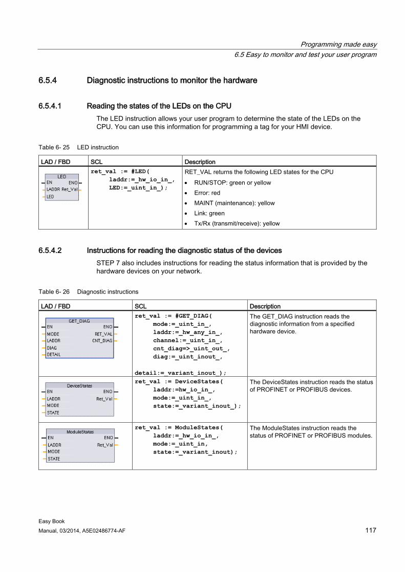
Programming made easy 6.5 Easy to monitor and test your user program
Easy Book Manual, 03/2014, A5E02486774-AF 117
6.5.4 Diagnostic instructions to monitor the hardware
6.5.4.1 Reading the states of the LEDs on the CPU The LED instruction allows your user program to determine the state of the LEDs on the CPU. You can use this information for programming a tag for your HMI device.
Table 6- 25 LED instruction
LAD / FBD SCL Description
ret_val := #LED( laddr:=_hw_io_in_, LED:=_uint_in_);
RET_VAL returns the following LED states for the CPU • RUN/STOP: green or yellow • Error: red • MAINT (maintenance): yellow • Link: green • Tx/Rx (transmit/receive): yellow
6.5.4.2 Instructions for reading the diagnostic status of the devices STEP 7 also includes instructions for reading the status information that is provided by the hardware devices on your network.
Table 6- 26 Diagnostic instructions
LAD / FBD SCL Description
ret_val := #GET_DIAG( mode:=_uint_in_, laddr:=_hw_any_in_, channel:=_uint_in_, cnt_diag=>_uint_out_, diag:=_uint_inout_, detail:=_variant_inout_);
The GET_DIAG instruction reads the diagnostic information from a specified hardware device.
ret_val := DeviceStates( laddr:=hw_io_in_, mode:=_uint_in_, state:=_variant_inout_);
The DeviceStates instruction reads the status of PROFINET or PROFIBUS devices.
ret_val := ModuleStates( laddr:=_hw_io_in_, mode:=_uint_in, state:=_variant_inout);
The ModuleStates instruction reads the status of PROFINET or PROFIBUS modules.
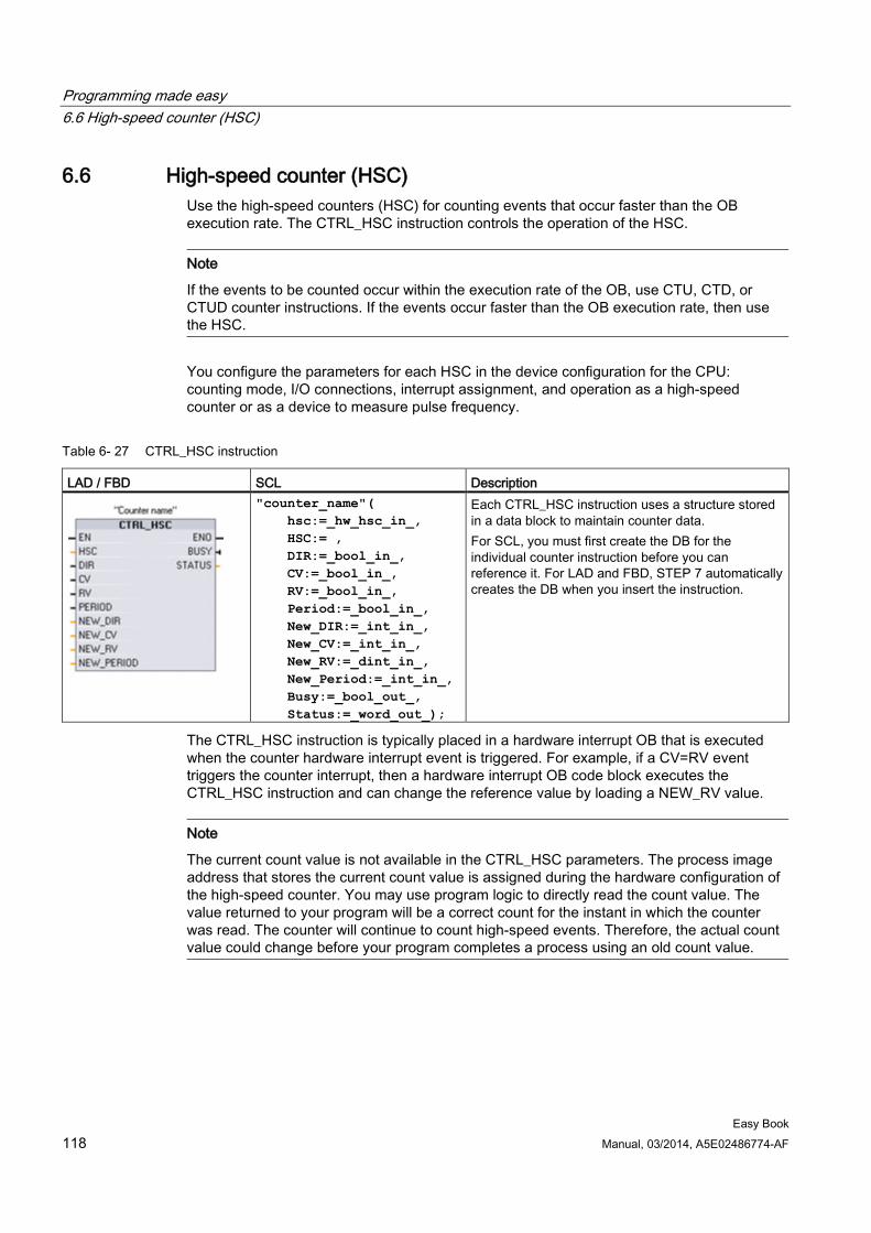
Programming made easy 6.6 High-speed counter (HSC)
Easy Book 118 Manual, 03/2014, A5E02486774-AF
6.6 High-speed counter (HSC) Use the high-speed counters (HSC) for counting events that occur faster than the OB execution rate. The CTRL_HSC instruction controls the operation of the HSC.
Note
If the events to be counted occur within the execution rate of the OB, use CTU, CTD, or CTUD counter instructions. If the events occur faster than the OB execution rate, then use the HSC.
You configure the parameters for each HSC in the device configuration for the CPU: counting mode, I/O connections, interrupt assignment, and operation as a high-speed counter or as a device to measure pulse frequency.
Table 6- 27 CTRL_HSC instruction
LAD / FBD SCL Description
"counter_name"( hsc:=_hw_hsc_in_, HSC:= , DIR:=_bool_in_, CV:=_bool_in_, RV:=_bool_in_, Period:=_bool_in_, New_DIR:=_int_in_, New_CV:=_int_in_, New_RV:=_dint_in_, New_Period:=_int_in_, Busy:=_bool_out_, Status:=_word_out_);
Each CTRL_HSC instruction uses a structure stored in a data block to maintain counter data. For SCL, you must first create the DB for the individual counter instruction before you can reference it. For LAD and FBD, STEP 7 automatically creates the DB when you insert the instruction.
The CTRL_HSC instruction is typically placed in a hardware interrupt OB that is executed when the counter hardware interrupt event is triggered. For example, if a CV=RV event triggers the counter interrupt, then a hardware interrupt OB code block executes the CTRL_HSC instruction and can change the reference value by loading a NEW_RV value.
Note
The current count value is not available in the CTRL_HSC parameters. The process image address that stores the current count value is assigned during the hardware configuration of the high-speed counter. You may use program logic to directly read the count value. The value returned to your program will be a correct count for the instant in which the counter was read. The counter will continue to count high-speed events. Therefore, the actual count value could change before your program completes a process using an old count value.
Programming made easy 6.6 High-speed counter (HSC)
Easy Book Manual, 03/2014, A5E02486774-AF 119
Some of the parameters for the HSC can be modified by your user program to provide program control of the counting process:
● Set the counting direction to a NEW_DIR value
● Set the current count value to a NEW_CV value
● Set the reference value to a NEW_RV value
● Set the period value (for frequency measurement mode) to a NEW_PERIOD value
If the following Boolean flag values are set to 1 when the CTRL_HSC instruction is executed, the corresponding NEW_xxx value is loaded to the counter. Multiple requests (more than one flag is set at the same time) are processed in a single execution of the CTRL_HSC instruction. Setting the following Boolean flag values to 0 results in no change.
● Setting DIR = 1 loads a NEW_DIR value.
● Setting CV = 1 loads a NEW_CV value.
● Setting RV = 1 loads a NEW_RV value
● Setting PERIOD = 1 loads a NEW_PERIOD value.
6.6.1 Operation of the high-speed counter High-speed counters (HSC) can count events that occur faster than the cyclic OB execution rate. If the events to be counted occur slower than the execution rate of the OB, you can use CTU, CTD, or CTUD standard counter instructions. If the events occur faster than the OB execution rate, then use the faster HSC device. The CTRL_HSC instruction allows your program to programmatically change some of the HSC parameters.
For example: You can use the HSC as an input for an incremental shaft encoder. The shaft encoder provides a specified number of counts per revolution and a reset pulse that occurs once per revolution. The clock(s) and the reset pulse from the shaft encoder provide the inputs to the HSC.
The HSC is loaded with the first of several presets, and the outputs are activated for the time period where the current count is less than the current preset. The HSC provides an interrupt when the current count is equal to preset, when reset occurs, and also when there is a direction change.
As each current-count-value-equals-preset-value interrupt event occurs, a new preset is loaded and the next state for the outputs is set. When the reset interrupt event occurs, the first preset and the first output states are set, and the cycle is repeated.
Since the interrupts occur at a much lower rate than the counting rate of the HSC, precise control of high-speed operations can be implemented with relatively minor impact to the scan cycle of the CPU. The method of interrupt attachment allows each load of a new preset to be performed in a separate interrupt routine for easy state control. Alternatively, all interrupt events can be processed in a single interrupt routine.
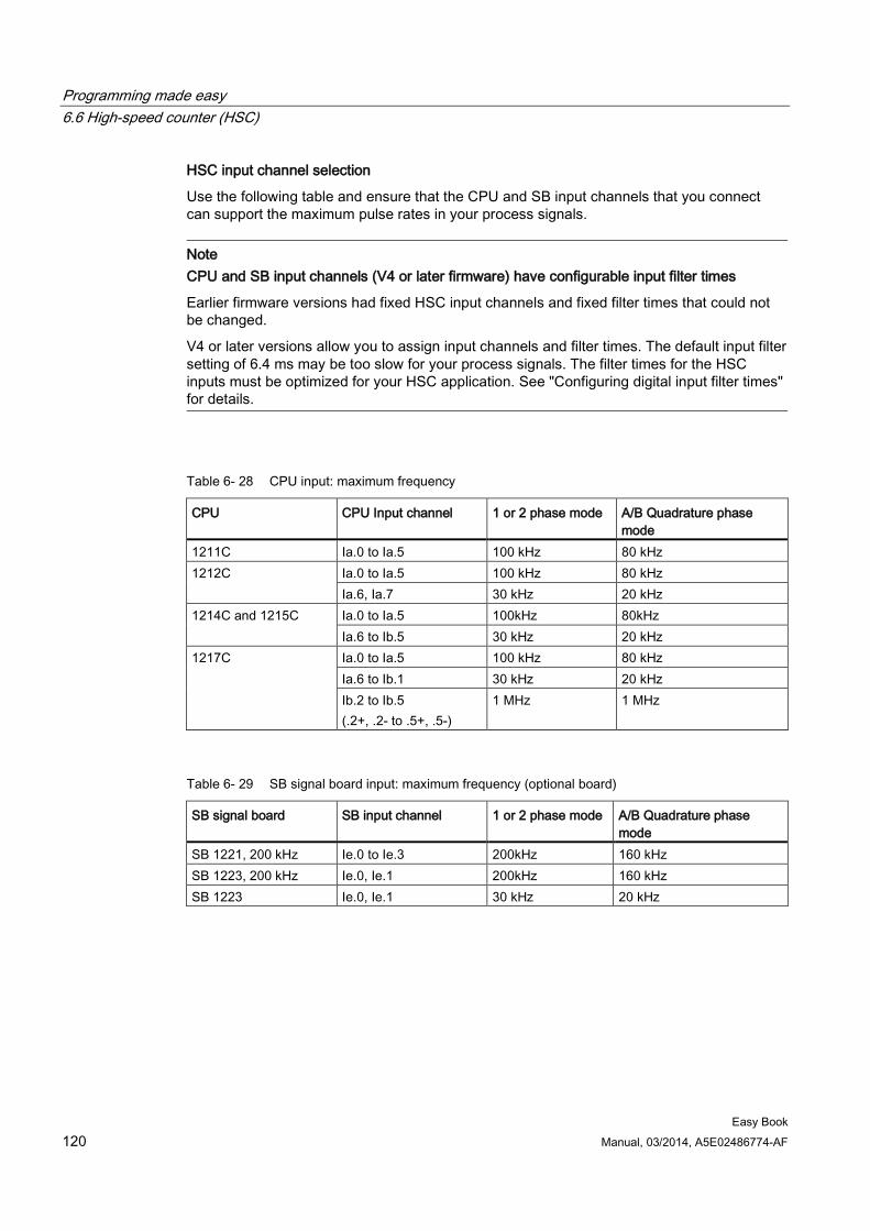
Programming made easy 6.6 High-speed counter (HSC)
Easy Book 120 Manual, 03/2014, A5E02486774-AF
HSC input channel selection
Use the following table and ensure that the CPU and SB input channels that you connect can support the maximum pulse rates in your process signals.
Note CPU and SB input channels (V4 or later firmware) have configurable input filter times
Earlier firmware versions had fixed HSC input channels and fixed filter times that could not be changed.
V4 or later versions allow you to assign input channels and filter times. The default input filter setting of 6.4 ms may be too slow for your process signals. The filter times for the HSC inputs must be optimized for your HSC application. See "Configuring digital input filter times" for details.
Table 6- 28 CPU input: maximum frequency
CPU CPU Input channel 1 or 2 phase mode A/B Quadrature phase mode
1211C Ia.0 to Ia.5 100 kHz 80 kHz 1212C Ia.0 to Ia.5 100 kHz 80 kHz
Ia.6, Ia.7 30 kHz 20 kHz 1214C and 1215C Ia.0 to Ia.5 100kHz 80kHz
Ia.6 to Ib.5 30 kHz 20 kHz 1217C Ia.0 to Ia.5 100 kHz 80 kHz
Ia.6 to Ib.1 30 kHz 20 kHz Ib.2 to Ib.5 (.2+, .2- to .5+, .5-)
1 MHz 1 MHz
Table 6- 29 SB signal board input: maximum frequency (optional board)
SB signal board SB input channel 1 or 2 phase mode A/B Quadrature phase mode
SB 1221, 200 kHz Ie.0 to Ie.3 200kHz 160 kHz SB 1223, 200 kHz Ie.0, Ie.1 200kHz 160 kHz SB 1223 Ie.0, Ie.1 30 kHz 20 kHz
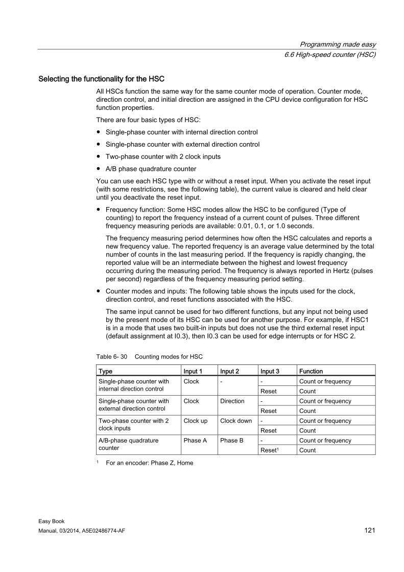
Programming made easy 6.6 High-speed counter (HSC)
Easy Book Manual, 03/2014, A5E02486774-AF 121
Selecting the functionality for the HSC All HSCs function the same way for the same counter mode of operation. Counter mode, direction control, and initial direction are assigned in the CPU device configuration for HSC function properties.
There are four basic types of HSC:
● Single-phase counter with internal direction control
● Single-phase counter with external direction control
● Two-phase counter with 2 clock inputs
● A/B phase quadrature counter
You can use each HSC type with or without a reset input. When you activate the reset input (with some restrictions, see the following table), the current value is cleared and held clear until you deactivate the reset input.
● Frequency function: Some HSC modes allow the HSC to be configured (Type of counting) to report the frequency instead of a current count of pulses. Three different frequency measuring periods are available: 0.01, 0.1, or 1.0 seconds.
The frequency measuring period determines how often the HSC calculates and reports a new frequency value. The reported frequency is an average value determined by the total number of counts in the last measuring period. If the frequency is rapidly changing, the reported value will be an intermediate between the highest and lowest frequency occurring during the measuring period. The frequency is always reported in Hertz (pulses per second) regardless of the frequency measuring period setting.
● Counter modes and inputs: The following table shows the inputs used for the clock, direction control, and reset functions associated with the HSC.
The same input cannot be used for two different functions, but any input not being used by the present mode of its HSC can be used for another purpose. For example, if HSC1 is in a mode that uses two built-in inputs but does not use the third external reset input (default assignment at I0.3), then I0.3 can be used for edge interrupts or for HSC 2.
Table 6- 30 Counting modes for HSC
Type Input 1 Input 2 Input 3 Function Single-phase counter with internal direction control
Clock - - Count or frequency Reset Count
Single-phase counter with external direction control
Clock Direction - Count or frequency Reset Count
Two-phase counter with 2 clock inputs
Clock up Clock down - Count or frequency Reset Count
A/B-phase quadrature counter
Phase A Phase B - Count or frequency Reset1 Count
1 For an encoder: Phase Z, Home
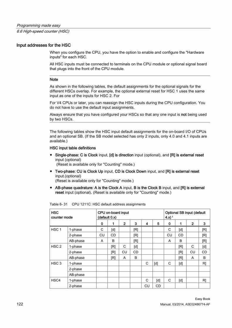
Programming made easy 6.6 High-speed counter (HSC)
Easy Book 122 Manual, 03/2014, A5E02486774-AF
Input addresses for the HSC When you configure the CPU, you have the option to enable and configure the "Hardware inputs" for each HSC.
All HSC inputs must be connected to terminals on the CPU module or optional signal board that plugs into the front of the CPU module.
Note
As shown in the following tables, the default assignments for the optional signals for the different HSCs overlap. For example, the optional external reset for HSC 1 uses the same input as one of the inputs for HSC 2. For
For V4 CPUs or later, you can reassign the HSC inputs during the CPU configuration. You do not have to use the default input assignments.
Always ensure that you have configured your HSCs so that any one input is not being used by two HSCs.
The following tables show the HSC input default assignments for the on-board I/O of CPUs and an optional SB. (If the SB model selected has only 2 inputs, only 4.0 and 4.1 inputs are available.)
HSC input table definitions
● Single-phase: C is Clock input, [d] is direction input (optional), and [R] is external reset input (optional) (Reset is available only for "Counting" mode.)
● Two-phase: CU is Clock Up input, CD is Clock Down input, and [R] is external reset input.(optional) (Reset is available only for "Counting" mode.)
● AB-phase quadrature: A is the Clock A input, B is the Clock B input, and [R] is external reset input (optional). (Reset is available only for "Counting" mode.)
Table 6- 31 CPU 1211C: HSC default address assignments
HSC counter mode
CPU on-board input (default 0.x)
Optional SB input (default 4.x) 1
0 1 2 3 4 5 0 1 2 3 HSC 1 1-phase C [d] [R] C [d] [R]
2-phase CU CD [R] CU CD [R] AB-phase A B [R] A B [R]
HSC 2 1-phase [R] C [d] [R] C [d] 2-phase [R] CU CD [R] CU CD AB-phase [R] A B [R] A B
HSC 3 1-phase C [d] C [d] R] 2-phase AB-phase
HSC4 1-phase C [d] C [d] R] 2-phase CU CD
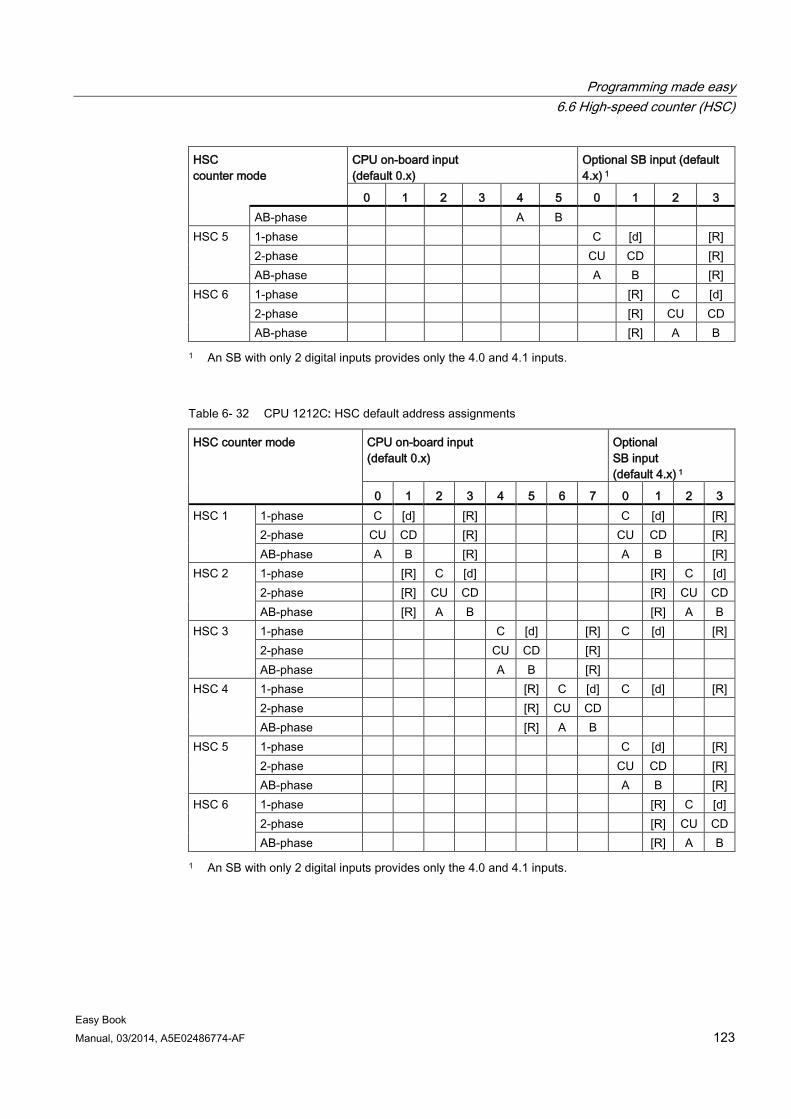
Programming made easy 6.6 High-speed counter (HSC)
Easy Book Manual, 03/2014, A5E02486774-AF 123
HSC counter mode
CPU on-board input (default 0.x)
Optional SB input (default 4.x) 1
0 1 2 3 4 5 0 1 2 3 AB-phase A B
HSC 5 1-phase C [d] [R] 2-phase CU CD [R] AB-phase A B [R]
HSC 6 1-phase [R] C [d] 2-phase [R] CU CD AB-phase [R] A B
1 An SB with only 2 digital inputs provides only the 4.0 and 4.1 inputs.
Table 6- 32 CPU 1212C: HSC default address assignments
HSC counter mode CPU on-board input (default 0.x)
Optional SB input (default 4.x) 1
0 1 2 3 4 5 6 7 0 1 2 3 HSC 1 1-phase C [d] [R] C [d] [R]
2-phase CU CD [R] CU CD [R] AB-phase A B [R] A B [R]
HSC 2 1-phase [R] C [d] [R] C [d] 2-phase [R] CU CD [R] CU CD AB-phase [R] A B [R] A B
HSC 3 1-phase C [d] [R] C [d] [R] 2-phase CU CD [R] AB-phase A B [R]
HSC 4 1-phase [R] C [d] C [d] [R] 2-phase [R] CU CD AB-phase [R] A B
HSC 5 1-phase C [d] [R] 2-phase CU CD [R] AB-phase A B [R]
HSC 6 1-phase [R] C [d] 2-phase [R] CU CD AB-phase [R] A B
1 An SB with only 2 digital inputs provides only the 4.0 and 4.1 inputs.
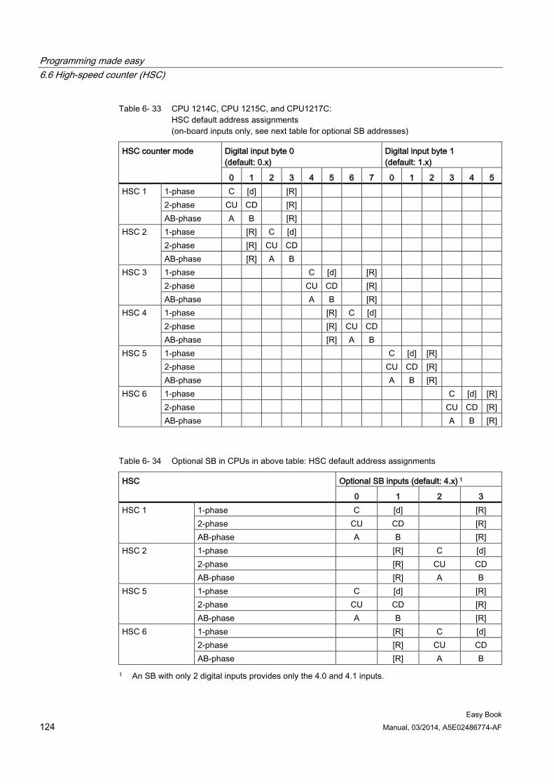
Programming made easy 6.6 High-speed counter (HSC)
Easy Book 124 Manual, 03/2014, A5E02486774-AF
Table 6- 33 CPU 1214C, CPU 1215C, and CPU1217C: HSC default address assignments (on-board inputs only, see next table for optional SB addresses)
HSC counter mode Digital input byte 0 (default: 0.x)
Digital input byte 1 (default: 1.x)
0 1 2 3 4 5 6 7 0 1 2 3 4 5 HSC 1 1-phase C [d] [R]
2-phase CU CD [R] AB-phase A B [R]
HSC 2 1-phase [R] C [d] 2-phase [R] CU CD AB-phase [R] A B
HSC 3 1-phase C [d] [R] 2-phase CU CD [R] AB-phase A B [R]
HSC 4 1-phase [R] C [d] 2-phase [R] CU CD AB-phase [R] A B
HSC 5 1-phase C [d] [R] 2-phase CU CD [R] AB-phase A B [R]
HSC 6 1-phase C [d] [R] 2-phase CU CD [R] AB-phase A B [R]
Table 6- 34 Optional SB in CPUs in above table: HSC default address assignments
HSC Optional SB inputs (default: 4.x) 1
0 1 2 3 HSC 1 1-phase C [d] [R]
2-phase CU CD [R] AB-phase A B [R]
HSC 2 1-phase [R] C [d] 2-phase [R] CU CD AB-phase [R] A B
HSC 5 1-phase C [d] [R] 2-phase CU CD [R] AB-phase A B [R]
HSC 6 1-phase [R] C [d] 2-phase [R] CU CD AB-phase [R] A B
1 An SB with only 2 digital inputs provides only the 4.0 and 4.1 inputs.
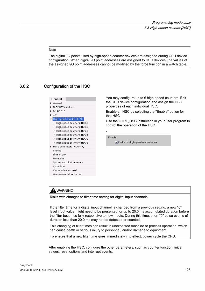
Programming made easy 6.6 High-speed counter (HSC)
Easy Book Manual, 03/2014, A5E02486774-AF 125
Note
The digital I/O points used by high-speed counter devices are assigned during CPU device configuration. When digital I/O point addresses are assigned to HSC devices, the values of the assigned I/O point addresses cannot be modified by the force function in a watch table.
6.6.2 Configuration of the HSC
You may configure up to 6 high-speed counters. Edit the CPU device configuration and assign the HSC properties of each individual HSC. Enable an HSC by selecting the "Enable" option for that HSC Use the CTRL_HSC instruction in your user program to control the operation of the HSC. .
WARNING
Risks with changes to filter time setting for digital input channels
If the filter time for a digital input channel is changed from a previous setting, a new "0" level input value might need to be presented for up to 20.0 ms accumulated duration before the filter becomes fully responsive to new inputs. During this time, short "0" pulse events of duration less than 20.0 ms may not be detected or counted.
This changing of filter times can result in unexpected machine or process operation, which can cause death or serious injury to personnel, and/or damage to equipment.
To ensure that a new filter time goes immediately into effect, power cycle the CPU.
After enabling the HSC, configure the other parameters, such as counter function, initial values, reset options and interrupt events.
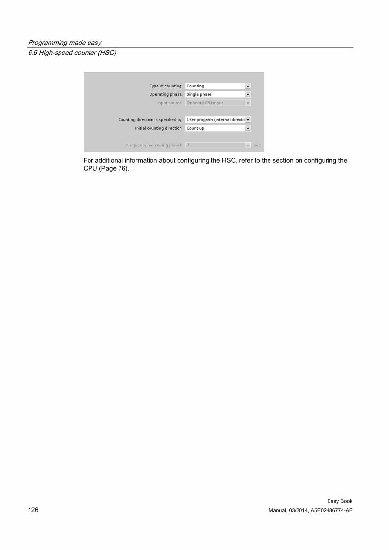
Programming made easy 6.6 High-speed counter (HSC)
Easy Book 126 Manual, 03/2014, A5E02486774-AF
For additional information about configuring the HSC, refer to the section on configuring the CPU (Page 76).
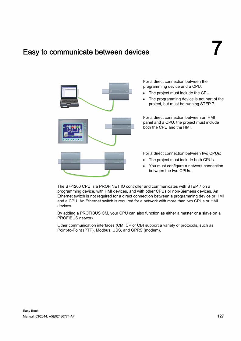
Easy Book Manual, 03/2014, A5E02486774-AF 127
Easy to communicate between devices 7
For a direct connection between the programming device and a CPU: • The project must include the CPU. • The programming device is not part of the
project, but must be running STEP 7.
For a direct connection between an HMI panel and a CPU, the project must include both the CPU and the HMI.
For a direct connection between two CPUs: • The project must include both CPUs. • You must configure a network connection
between the two CPUs.
The S7-1200 CPU is a PROFINET IO controller and communicates with STEP 7 on a programming device, with HMI devices, and with other CPUs or non-Siemens devices. An Ethernet switch is not required for a direct connection between a programming device or HMI and a CPU. An Ethernet switch is required for a network with more than two CPUs or HMI devices.
By adding a PROFIBUS CM, your CPU can also function as either a master or a slave on a PROFIBUS network.
Other communication interfaces (CM, CP or CB) support a variety of protocols, such as Point-to-Point (PTP), Modbus, USS, and GPRS (modem).
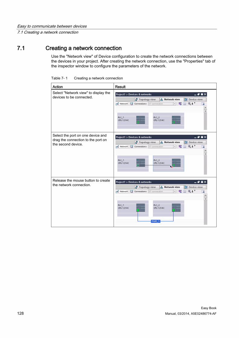
Easy to communicate between devices 7.1 Creating a network connection
Easy Book 128 Manual, 03/2014, A5E02486774-AF
7.1 Creating a network connection Use the "Network view" of Device configuration to create the network connections between the devices in your project. After creating the network connection, use the "Properties" tab of the inspector window to configure the parameters of the network.
Table 7- 1 Creating a network connection
Action Result Select "Network view" to display the devices to be connected.
Select the port on one device and drag the connection to the port on the second device.
Release the mouse button to create the network connection.
Easy to communicate between devices 7.2 Communication options
Easy Book Manual, 03/2014, A5E02486774-AF 129
7.2 Communication options The S7-1200 offers several types of communication between CPUs and programming devices, HMIs, and other CPUs.
WARNING
If an attacker can physically access your networks, the attacker can possibly read and write data.
The TIA Portal, the CPU, and HMIs (except HMIs using GET/PUT) use secure communication that protects against replay and "man-in-the-middle" attacks. Once communication is enabled, the exchange of signed messages takes place in clear text which allows an attacker to read data, but protects against unauthorized writing of data. The TIA Portal, not the communication process, encrypts the data of know-how protected blocks.
All other forms of communication (I/O exchange through PROFIBUS, PROFINET, AS-i, or other I/O bus, GET/PUT, T-Block, and communication modules (CM)) have no security features. You must protect these forms of communication by limiting physical access. If an attacker can physically access your networks utilizing these forms of communication, the attacker can possibly read and write data.
For security information and recommendations, please see our "Operational Guidelines for Industrial Security" on the Siemens Service and Support site.
PROFINET PROFINET is used for exchanging data through the user program with other communications partners through Ethernet:
● PROFINET supports 16 IO devices with a maximum of 256 submodules. PROFIBUS allows 3 independent PROFIBUS DP Masters, supporting 32 slaves per DP master, with a maximum of 512 modules per DP master.
● S7 communication
● User Datagram Protocol (UDP) protocol
● ISO on TCP (RFC 1006)
● Transport Control Protocol (TCP)
PROFINET RT IO controller As an IO controller using PROFINET RT, the CPU communicates with up to 16 PN devices on the local PN network or through a PN/PN coupler (link). Refer to PROFIBUS and PROFINET International, PI (www.us.profinet.com) for more information.
Easy to communicate between devices 7.2 Communication options
Easy Book 130 Manual, 03/2014, A5E02486774-AF
PROFIBUS PROFIBUS is used for exchanging data through the user program with other communications partners through the PROFIBUS network:
● With CM 1242-5, the CPU operates as a PROFIBUS DP slave.
● With CM 1243-5, the CPU operates as a PROFIBUS DP master class1.
● PROFIBUS DP Slaves, PROFIBUS DP Masters, and AS-i (the 3 left-side communication modules) and PROFINET are separate communications networks that do not limit each other.
AS-i The S7-1200 CM 1243-2 AS-i Master allows the attachment of an AS-i network to an S7-1200 CPU.
CPU-to-CPU S7 communication You can create a communication connection to a partner station and use the GET and PUT instructions to communicate with S7 CPUs.
Teleservice communication In TeleService via GPRS, an engineering station on which STEP 7 is installed communicates via the GSM network and the Internet with a SIMATIC S7-1200 station with a CP 1242-7. The connection runs via a telecontrol server that serves as an intermediary and is connected to the Internet.
IO-Link The S7-1200 SM 1278 4xIO-Link Master enables IO-Link devices to connect to an S7 1200 CPU.
See also Siemens service and support site (http://www.industry.siemens.com/topics/global/en/industrial-security/Documents/operational_guidelines_industrial_security_en.pdf)
Easy to communicate between devices 7.3 Number of asynchronous communication connections
Easy Book Manual, 03/2014, A5E02486774-AF 131
7.3 Number of asynchronous communication connections The CPU supports the following maximum number of simultaneous, asynchronous communication connections for PROFINET and PROFIBUS:
● 8 connections for Open User Communications (active or passive): TSEND_C, TRCV_C, TCON, TDISCON, TSEND, and TRCV.
● 3 CPU-to-CPU S7 connections for server GET/PUT data
● 8 CPU-to-CPU S7 connections for client GET/PUT data
Note
S7-1200, S7-300, and S7-400 CPUs use the GET and PUT instructions for CPU-to-CPU S7 communication. An S7-200 CPU uses ETHx_XFER instructions for CPU-to-CPU S7 communication.
● HMI connections: You can configure the number of HMI connections required for your application through the TIA Portal.
● PG connections: The CPU provides connections to support 1 programming device (PG).
● Web server (HTTP) connections: The CPU provides connections for the Web server.
Note
The Open User Communications, S7 connection, HMI, programming device, and Web server (HTTP) communication connections may utilize multiple connection resources based upon the features currently being used.
Easy to communicate between devices 7.4 PROFINET and PROFIBUS instructions
Easy Book 132 Manual, 03/2014, A5E02486774-AF
7.4 PROFINET and PROFIBUS instructions
PROFINET instructions The TSEND_C and TRCV_C instructions make PROFINET communications simpler by combining the functionality of the TCON and TDISCON instructions with the TSEND or TRCV instruction.
● TSEND_C establishes a TCP or ISO on TCP communication connection to a partner station, sends data, and can terminate the connection. After the connection is set up and established, it is automatically maintained and monitored by the CPU. TSEND_C combines the functions of the TCON, TDISCON and TSEND instructions into one instruction.
● TRCV_C establishes a TCP or ISO-on-TCP communication connection to a partner CPU, receives data, and can terminate the connection. After the connection is set up and established, it is automatically maintained and monitored by the CPU. The TRCV_C instruction combines the functions of the TCON, TDISCON, and TRCV instructions into one instruction.
The TCON, TDISCON, TSEND and TRCV instructions are also supported.
Use the TUSEND and the TURCV instructions to transmit or receive data via UDP. TUSEND and TURCV (as well as TSEND, TRCV, TCON, TDISCON) function asynchronously, which means that the processing of the job extends over several instruction calls.
Use the IP_CONF instruction to change the IP configuration parameters from your user program. IP_CONF works asynchronously. The execution extends over multiple calls.
PROFIBUS instructions The DPNRM_DG (read diagnostics) instruction reads the current diagnostic data of a DP slave in the format specified by EN 50 170 Volume 2, PROFIBUS.
Distributed I/O instructions for PROFINET, PROFIBUS and AS-i You can use the following instructions with PROFINET, PROFIBUS, and GPRS.
● Use the RDREC (read record) and WRREC (write record) instructions to transfer a specified data record between a component, such as a module in a central rack or a distributed component (PROFIBUS DP or PROFINET IO).
● Use the RALRM (read alarm) instruction to read an interrupt and its information from a DP slave or PROFINET IO device component. The information in the output parameters contains the start information of the called OB as well as information of the interrupt source.
● Use the DPRD_DAT (read consistent data) and DPWR_DAT (write consistent data) instructions to transfer consistent data areas greater than 64 bytes from or to a DP standard slave.
● For PROFIBUS only, use the DPNRM_DG instruction to read the current diagnostic data of a DP slave in the format specified by EN 50 170 Volume 2, PROFIBUS.
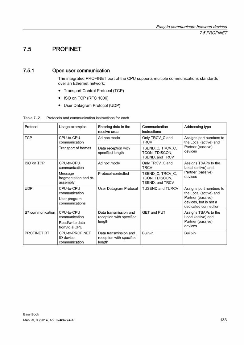
Easy to communicate between devices 7.5 PROFINET
Easy Book Manual, 03/2014, A5E02486774-AF 133
7.5 PROFINET
7.5.1 Open user communication The integrated PROFINET port of the CPU supports multiple communications standards over an Ethernet network:
● Transport Control Protocol (TCP)
● ISO on TCP (RFC 1006)
● User Datagram Protocol (UDP)
Table 7- 2 Protocols and communication instructions for each
Protocol Usage examples Entering data in the receive area
Communication instructions
Addressing type
TCP CPU-to-CPU communication Transport of frames
Ad hoc mode Only TRCV_C and TRCV
Assigns port numbers to the Local (active) and Partner (passive) devices
Data reception with specified length
TSEND_C, TRCV_C, TCON, TDISCON, TSEND, and TRCV
ISO on TCP CPU-to-CPU communication Message fragmentation and re-assembly
Ad hoc mode Only TRCV_C and TRCV
Assigns TSAPs to the Local (active) and Partner (passive) devices
Protocol-controlled TSEND_C, TRCV_C, TCON, TDISCON, TSEND, and TRCV
UDP CPU-to-CPU communication User program communications
User Datagram Protocol TUSEND and TURCV Assigns port numbers to the Local (active) and Partner (passive) devices, but is not a dedicated connection
S7 communication CPU-to-CPU communication Read/write data from/to a CPU
Data transmission and reception with specified length
GET and PUT Assigns TSAPs to the Local (active) and Partner (passive) devices
PROFINET RT CPU-to-PROFINET IO device communication
Data transmission and reception with specified length
Built-in Built-in
Easy to communicate between devices 7.5 PROFINET
Easy Book 134 Manual, 03/2014, A5E02486774-AF
7.5.1.1 Ad hoc mode Typically, TCP and ISO-on-TCP receive data packets of a specified length, ranging from 1 to 8192 bytes. However, the TRCV_C and TRCV communication instructions also provide an "ad hoc" communications mode that can receive data packets of a variable length from 1 to 1472 bytes.
Note
If you store the data in an "optimized" DB (symbolic only), you can receive data only in arrays of Byte, Char, USInt, and SInt data types.
To configure the TRCV_C or TRCV instruction for ad hoc mode, set the ADHOC instruction input parameter.
If you do not call the TRCV_C or TRCV instruction in ad hoc mode frequently, you could receive more than one packet in one call. For example: If you were to receive five 100-byte packets with one call, TCP would deliver these five packets as one 500-byte packet, while ISO-on-TCP would restructure the packets into five 100-byte packets.
7.5.1.2 Connection IDs for the Open user communication instructions When you insert the TSEND_C, TRCV_C or TCON PROFINET instructions into your user program, STEP 7 creates an instance DB to configure the communications channel (or connection) between the devices. Use the "Properties" of the instruction to configure the parameters for the connection. Among the parameters is the connection ID for that connection.
● The connection ID must be unique for the CPU. Each connection that you create must have a different DB and connection ID.
● Both the local CPU and the partner CPU can use the same connection ID number for the same connection, but the connection ID numbers are not required to match. The connection ID number is relevant only for the PROFINET instructions within the user program of the individual CPU.
● You can use any number for the connection ID of the CPU. However, configuring the connection IDs sequentially from "1" provides an easy method for tracking the number of connections in use for a specific CPU.
Note
Each TSEND_C, TRCV_C or TCON instruction in your user program creates a new connection. It is important to use the correct connection ID for each connection.
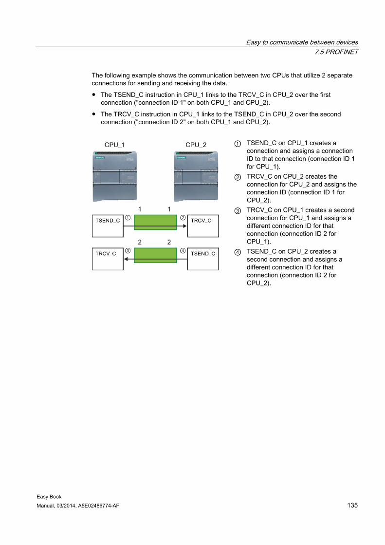
Easy to communicate between devices 7.5 PROFINET
Easy Book Manual, 03/2014, A5E02486774-AF 135
The following example shows the communication between two CPUs that utilize 2 separate connections for sending and receiving the data.
● The TSEND_C instruction in CPU_1 links to the TRCV_C in CPU_2 over the first connection ("connection ID 1" on both CPU_1 and CPU_2).
● The TRCV_C instruction in CPU_1 links to the TSEND_C in CPU_2 over the second connection ("connection ID 2" on both CPU_1 and CPU_2).
① TSEND_C on CPU_1 creates a connection and assigns a connection ID to that connection (connection ID 1 for CPU_1).
② TRCV_C on CPU_2 creates the connection for CPU_2 and assigns the connection ID (connection ID 1 for CPU_2).
③ TRCV_C on CPU_1 creates a second connection for CPU_1 and assigns a different connection ID for that connection (connection ID 2 for CPU_1).
④ TSEND_C on CPU_2 creates a second connection and assigns a different connection ID for that connection (connection ID 2 for CPU_2).
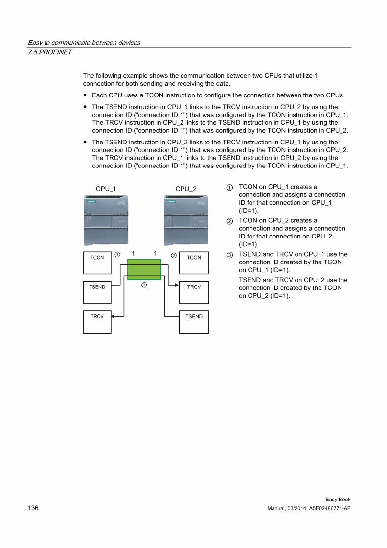
Easy to communicate between devices 7.5 PROFINET
Easy Book 136 Manual, 03/2014, A5E02486774-AF
The following example shows the communication between two CPUs that utilize 1 connection for both sending and receiving the data.
● Each CPU uses a TCON instruction to configure the connection between the two CPUs.
● The TSEND instruction in CPU_1 links to the TRCV instruction in CPU_2 by using the connection ID ("connection ID 1") that was configured by the TCON instruction in CPU_1. The TRCV instruction in CPU_2 links to the TSEND instruction in CPU_1 by using the connection ID ("connection ID 1") that was configured by the TCON instruction in CPU_2.
● The TSEND instruction in CPU_2 links to the TRCV instruction in CPU_1 by using the connection ID ("connection ID 1") that was configured by the TCON instruction in CPU_2. The TRCV instruction in CPU_1 links to the TSEND instruction in CPU_2 by using the connection ID ("connection ID 1") that was configured by the TCON instruction in CPU_1.
① TCON on CPU_1 creates a connection and assigns a connection ID for that connection on CPU_1 (ID=1).
② TCON on CPU_2 creates a connection and assigns a connection ID for that connection on CPU_2 (ID=1).
③ TSEND and TRCV on CPU_1 use the connection ID created by the TCON on CPU_1 (ID=1). TSEND and TRCV on CPU_2 use the connection ID created by the TCON on CPU_2 (ID=1).
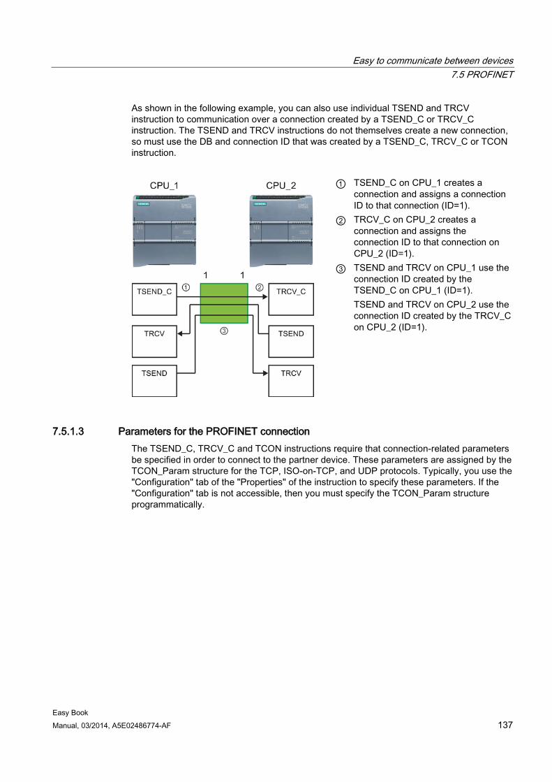
Easy to communicate between devices 7.5 PROFINET
Easy Book Manual, 03/2014, A5E02486774-AF 137
As shown in the following example, you can also use individual TSEND and TRCV instruction to communication over a connection created by a TSEND_C or TRCV_C instruction. The TSEND and TRCV instructions do not themselves create a new connection, so must use the DB and connection ID that was created by a TSEND_C, TRCV_C or TCON instruction.
① TSEND_C on CPU_1 creates a connection and assigns a connection ID to that connection (ID=1).
② TRCV_C on CPU_2 creates a connection and assigns the connection ID to that connection on CPU_2 (ID=1).
③ TSEND and TRCV on CPU_1 use the connection ID created by the TSEND_C on CPU_1 (ID=1). TSEND and TRCV on CPU_2 use the connection ID created by the TRCV_C on CPU_2 (ID=1).
7.5.1.3 Parameters for the PROFINET connection The TSEND_C, TRCV_C and TCON instructions require that connection-related parameters be specified in order to connect to the partner device. These parameters are assigned by the TCON_Param structure for the TCP, ISO-on-TCP, and UDP protocols. Typically, you use the "Configuration" tab of the "Properties" of the instruction to specify these parameters. If the "Configuration" tab is not accessible, then you must specify the TCON_Param structure programmatically.
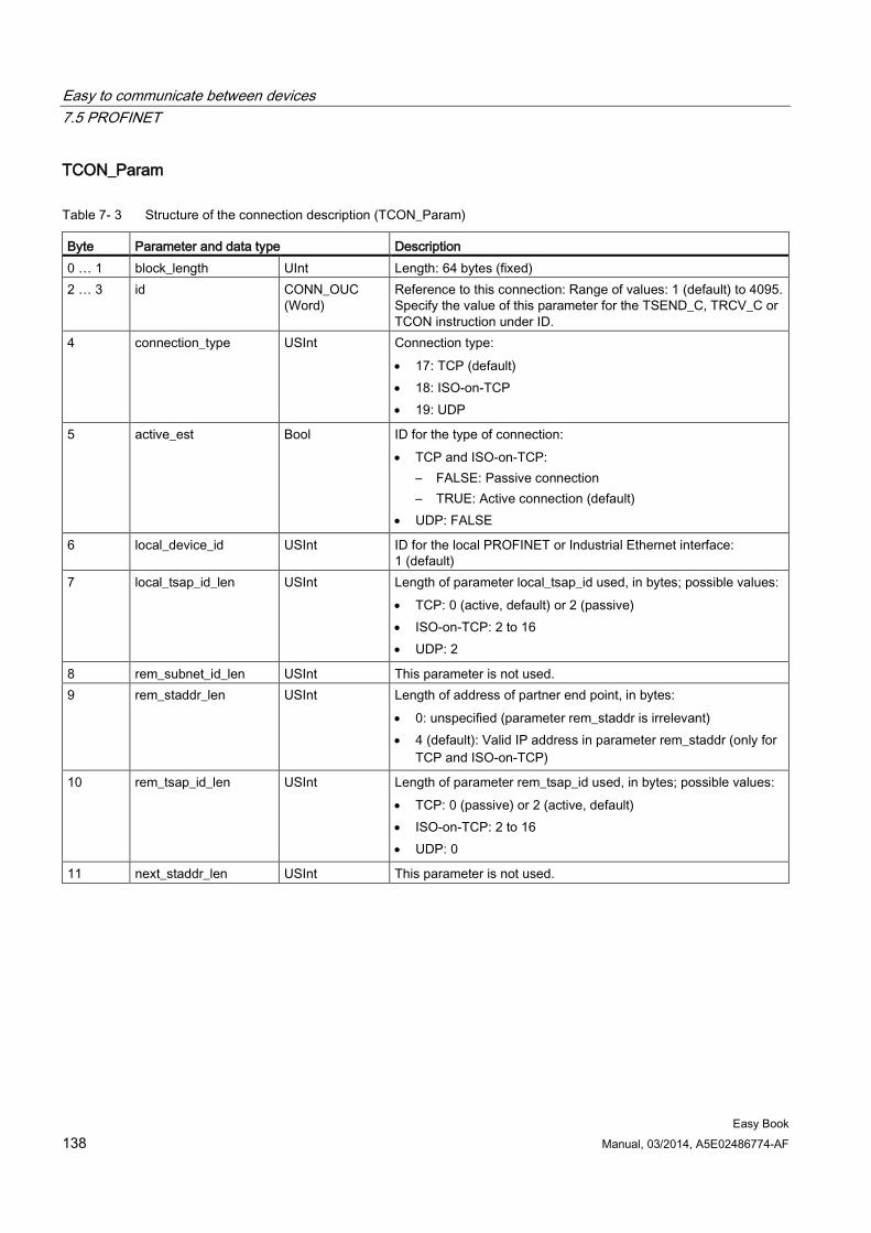
Easy to communicate between devices 7.5 PROFINET
Easy Book 138 Manual, 03/2014, A5E02486774-AF
TCON_Param
Table 7- 3 Structure of the connection description (TCON_Param)
Byte Parameter and data type Description 0 … 1 block_length UInt Length: 64 bytes (fixed) 2 … 3 id CONN_OUC
(Word) Reference to this connection: Range of values: 1 (default) to 4095. Specify the value of this parameter for the TSEND_C, TRCV_C or TCON instruction under ID.
4 connection_type USInt Connection type: • 17: TCP (default) • 18: ISO-on-TCP • 19: UDP
5 active_est Bool ID for the type of connection: • TCP and ISO-on-TCP:
– FALSE: Passive connection – TRUE: Active connection (default)
• UDP: FALSE
6 local_device_id USInt ID for the local PROFINET or Industrial Ethernet interface: 1 (default)
7 local_tsap_id_len USInt Length of parameter local_tsap_id used, in bytes; possible values: • TCP: 0 (active, default) or 2 (passive) • ISO-on-TCP: 2 to 16 • UDP: 2
8 rem_subnet_id_len USInt This parameter is not used. 9 rem_staddr_len USInt Length of address of partner end point, in bytes:
• 0: unspecified (parameter rem_staddr is irrelevant) • 4 (default): Valid IP address in parameter rem_staddr (only for
TCP and ISO-on-TCP)
10 rem_tsap_id_len USInt Length of parameter rem_tsap_id used, in bytes; possible values: • TCP: 0 (passive) or 2 (active, default) • ISO-on-TCP: 2 to 16 • UDP: 0
11 next_staddr_len USInt This parameter is not used.
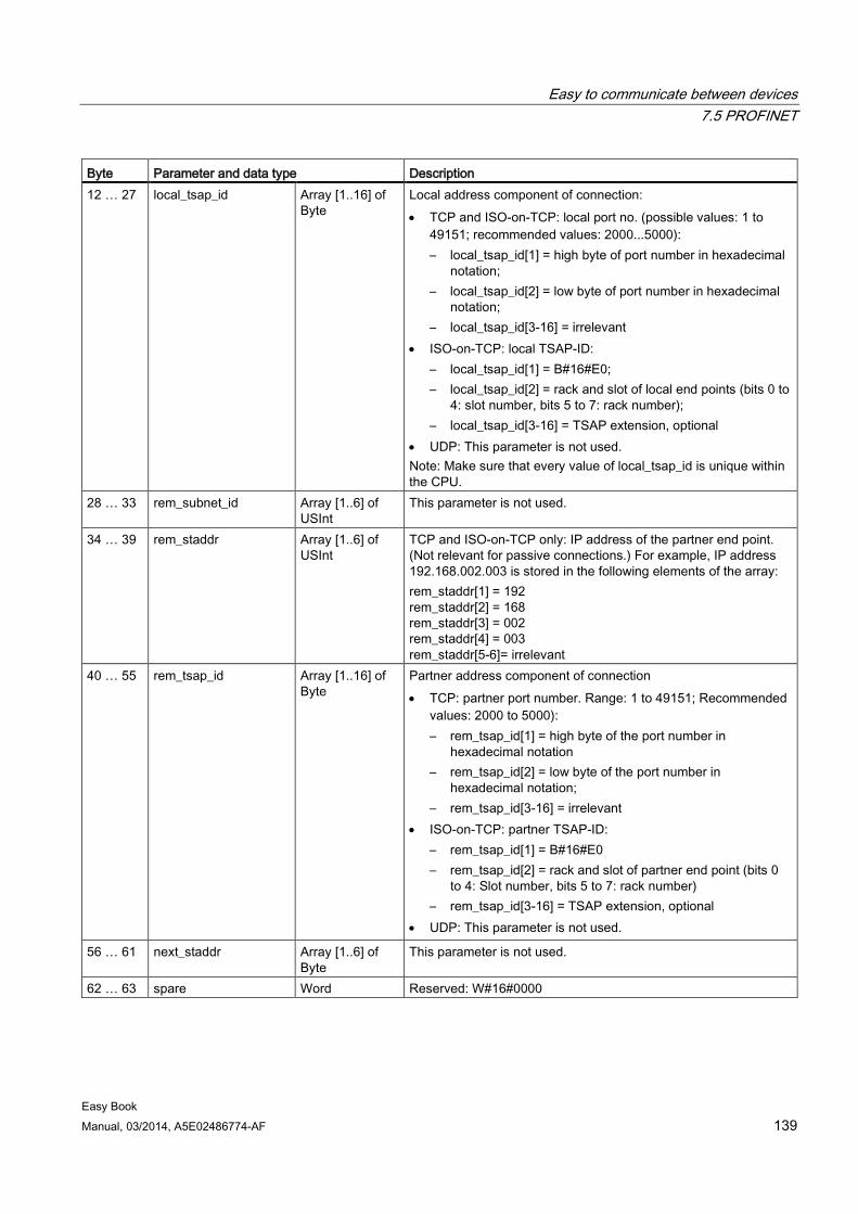
Easy to communicate between devices 7.5 PROFINET
Easy Book Manual, 03/2014, A5E02486774-AF 139
Byte Parameter and data type Description 12 … 27 local_tsap_id Array [1..16] of
Byte Local address component of connection: • TCP and ISO-on-TCP: local port no. (possible values: 1 to
49151; recommended values: 2000...5000): – local_tsap_id[1] = high byte of port number in hexadecimal
notation; – local_tsap_id[2] = low byte of port number in hexadecimal
notation; – local_tsap_id[3-16] = irrelevant
• ISO-on-TCP: local TSAP-ID: – local_tsap_id[1] = B#16#E0; – local_tsap_id[2] = rack and slot of local end points (bits 0 to
4: slot number, bits 5 to 7: rack number); – local_tsap_id[3-16] = TSAP extension, optional
• UDP: This parameter is not used. Note: Make sure that every value of local_tsap_id is unique within the CPU.
28 … 33 rem_subnet_id Array [1..6] of USInt
This parameter is not used.
34 … 39 rem_staddr Array [1..6] of USInt
TCP and ISO-on-TCP only: IP address of the partner end point. (Not relevant for passive connections.) For example, IP address 192.168.002.003 is stored in the following elements of the array: rem_staddr[1] = 192 rem_staddr[2] = 168 rem_staddr[3] = 002 rem_staddr[4] = 003 rem_staddr[5-6]= irrelevant
40 … 55 rem_tsap_id Array [1..16] of Byte
Partner address component of connection • TCP: partner port number. Range: 1 to 49151; Recommended
values: 2000 to 5000): – rem_tsap_id[1] = high byte of the port number in
hexadecimal notation – rem_tsap_id[2] = low byte of the port number in
hexadecimal notation; – rem_tsap_id[3-16] = irrelevant
• ISO-on-TCP: partner TSAP-ID: – rem_tsap_id[1] = B#16#E0 – rem_tsap_id[2] = rack and slot of partner end point (bits 0
to 4: Slot number, bits 5 to 7: rack number) – rem_tsap_id[3-16] = TSAP extension, optional
• UDP: This parameter is not used.
56 … 61 next_staddr Array [1..6] of Byte
This parameter is not used.
62 … 63 spare Word Reserved: W#16#0000
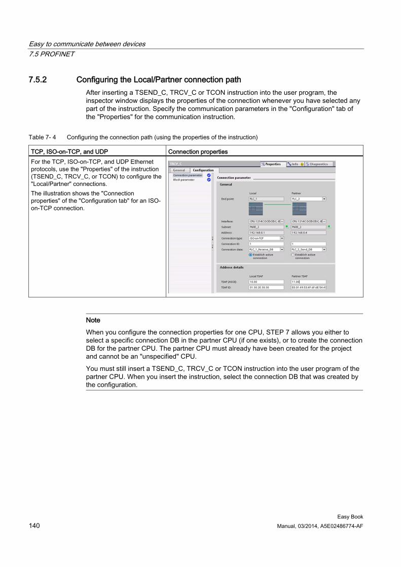
Easy to communicate between devices 7.5 PROFINET
Easy Book 140 Manual, 03/2014, A5E02486774-AF
7.5.2 Configuring the Local/Partner connection path After inserting a TSEND_C, TRCV_C or TCON instruction into the user program, the inspector window displays the properties of the connection whenever you have selected any part of the instruction. Specify the communication parameters in the "Configuration" tab of the "Properties" for the communication instruction.
Table 7- 4 Configuring the connection path (using the properties of the instruction)
TCP, ISO-on-TCP, and UDP Connection properties For the TCP, ISO-on-TCP, and UDP Ethernet protocols, use the "Properties" of the instruction (TSEND_C, TRCV_C, or TCON) to configure the "Local/Partner" connections. The illustration shows the "Connection properties" of the "Configuration tab" for an ISO-on-TCP connection.
Note
When you configure the connection properties for one CPU, STEP 7 allows you either to select a specific connection DB in the partner CPU (if one exists), or to create the connection DB for the partner CPU. The partner CPU must already have been created for the project and cannot be an "unspecified" CPU.
You must still insert a TSEND_C, TRCV_C or TCON instruction into the user program of the partner CPU. When you insert the instruction, select the connection DB that was created by the configuration.
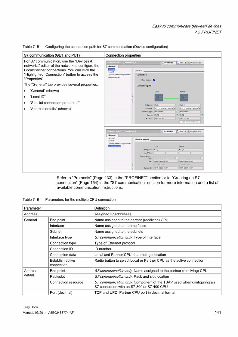
Easy to communicate between devices 7.5 PROFINET
Easy Book Manual, 03/2014, A5E02486774-AF 141
Table 7- 5 Configuring the connection path for S7 communication (Device configuration)
S7 communication (GET and PUT) Connection properties For S7 communication, use the "Devices & networks" editor of the network to configure the Local/Partner connections. You can click the "Highlighted: Connection" button to access the "Properties". The "General" tab provides several properties: • "General" (shown) • "Local ID" • "Special connection properties" • "Address details" (shown)
Refer to "Protocols" (Page 133) in the "PROFINET" section or to "Creating an S7 connection" (Page 154) in the "S7 communication" section for more information and a list of available communication instructions.
Table 7- 6 Parameters for the multiple CPU connection
Parameter Definition Address Assigned IP addresses General End point Name assigned to the partner (receiving) CPU
Interface Name assigned to the interfaces Subnet Name assigned to the subnets Interface type S7 communication only: Type of interface Connection type Type of Ethernet protocol Connection ID ID number Connection data Local and Partner CPU data storage location Establish active connection
Radio button to select Local or Partner CPU as the active connection
Address details
End point S7 communication only: Name assigned to the partner (receiving) CPU Rack/slot S7 communication only: Rack and slot location Connection resource S7 communication only: Component of the TSAP used when configuring an
S7 connection with an S7-300 or S7-400 CPU Port (decimal): TCP and UPD: Partner CPU port in decimal format
Easy to communicate between devices 7.6 PROFIBUS
Easy Book 142 Manual, 03/2014, A5E02486774-AF
Parameter Definition TSAP 1 and Subnet ID: ISO on TCP (RFC 1006) and S7 communication: Local and partner CPU
TSAPs in ASCII and hexadecimal formats 1 When configuring a connection with an S7-1200 CPU for ISO-on-TCP, use only ASCII characters in the TSAP extension
for the passive communication partners.
Transport Service Access Points (TSAPs) Using TSAPs, ISO on TCP protocol and S7 communication allows multiple connections to a single IP address (up to 64K connections). TSAPs uniquely identify these communication end point connections to an IP address.
In the "Address Details" section of the Connection Parameters dialog, you define the TSAPs to be used. The TSAP of a connection in the CPU is entered in the "Local TSAP" field. The TSAP assigned for the connection in your partner CPU is entered under the "Partner TSAP" field.
Port Numbers With TCP and UDP protocols, the connection parameter configuration of the Local (active) connection CPU must specify the remote IP address and port number of the Partner (passive) connection CPU.
In the "Address Details" section of the Connection Parameters dialog, you define the ports to be used. The port of a connection in the CPU is entered in the "Local Port" field. The port assigned for the connection in your partner CPU is entered under the "Partner Port" field.
7.6 PROFIBUS A PROFIBUS system uses a bus master to poll slave devices distributed in a multi-drop fashion on an RS485 serial bus. A PROFIBUS slave is any peripheral device (I/O transducer, valve, motor drive, or other measuring device) which processes information and sends its output to the master. The slave forms a passive station on the network since it does not have bus access rights, and can only acknowledge received messages, or send response messages to the master upon request. All PROFIBUS slaves have the same priority, and all network communication originates from the master.
A PROFIBUS master forms an "active station" on the network. PROFIBUS DP defines two classes of masters. A class 1 master (normally a central programmable controller (PLC) or a PC running special software) handles the normal communication or exchange of data with the slaves assigned to it. A class 2 master (usually a configuration device, such as a laptop or programming console used for commissioning, maintenance, or diagnostics purposes) is a special device primarily used for commissioning slaves and for diagnostic purposes.
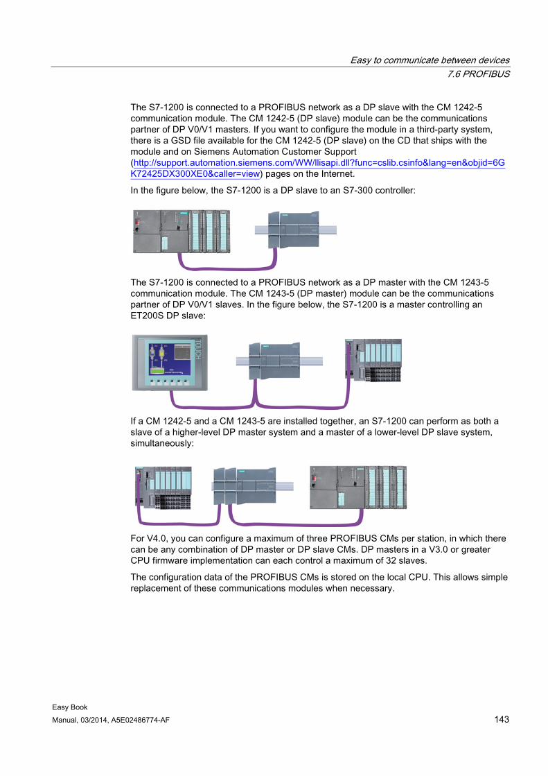
Easy to communicate between devices 7.6 PROFIBUS
Easy Book Manual, 03/2014, A5E02486774-AF 143
The S7-1200 is connected to a PROFIBUS network as a DP slave with the CM 1242-5 communication module. The CM 1242-5 (DP slave) module can be the communications partner of DP V0/V1 masters. If you want to configure the module in a third-party system, there is a GSD file available for the CM 1242-5 (DP slave) on the CD that ships with the module and on Siemens Automation Customer Support (http://support.automation.siemens.com/WW/llisapi.dll?func=cslib.csinfo&lang=en&objid=6GK72425DX300XE0&caller=view) pages on the Internet.
In the figure below, the S7-1200 is a DP slave to an S7-300 controller:
The S7-1200 is connected to a PROFIBUS network as a DP master with the CM 1243-5 communication module. The CM 1243-5 (DP master) module can be the communications partner of DP V0/V1 slaves. In the figure below, the S7-1200 is a master controlling an ET200S DP slave:
If a CM 1242-5 and a CM 1243-5 are installed together, an S7-1200 can perform as both a slave of a higher-level DP master system and a master of a lower-level DP slave system, simultaneously:
For V4.0, you can configure a maximum of three PROFIBUS CMs per station, in which there can be any combination of DP master or DP slave CMs. DP masters in a V3.0 or greater CPU firmware implementation can each control a maximum of 32 slaves.
The configuration data of the PROFIBUS CMs is stored on the local CPU. This allows simple replacement of these communications modules when necessary.
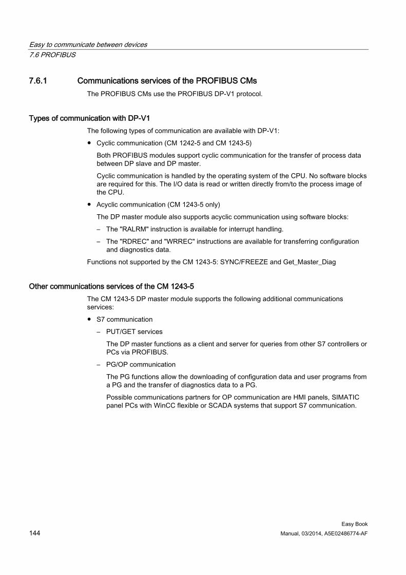
Easy to communicate between devices 7.6 PROFIBUS
Easy Book 144 Manual, 03/2014, A5E02486774-AF
7.6.1 Communications services of the PROFIBUS CMs The PROFIBUS CMs use the PROFIBUS DP-V1 protocol.
Types of communication with DP-V1 The following types of communication are available with DP-V1:
● Cyclic communication (CM 1242-5 and CM 1243-5)
Both PROFIBUS modules support cyclic communication for the transfer of process data between DP slave and DP master.
Cyclic communication is handled by the operating system of the CPU. No software blocks are required for this. The I/O data is read or written directly from/to the process image of the CPU.
● Acyclic communication (CM 1243-5 only)
The DP master module also supports acyclic communication using software blocks:
– The "RALRM" instruction is available for interrupt handling.
– The "RDREC" and "WRREC" instructions are available for transferring configuration and diagnostics data.
Functions not supported by the CM 1243-5: SYNC/FREEZE and Get_Master_Diag
Other communications services of the CM 1243-5 The CM 1243-5 DP master module supports the following additional communications services:
● S7 communication
– PUT/GET services
The DP master functions as a client and server for queries from other S7 controllers or PCs via PROFIBUS.
– PG/OP communication
The PG functions allow the downloading of configuration data and user programs from a PG and the transfer of diagnostics data to a PG.
Possible communications partners for OP communication are HMI panels, SIMATIC panel PCs with WinCC flexible or SCADA systems that support S7 communication.
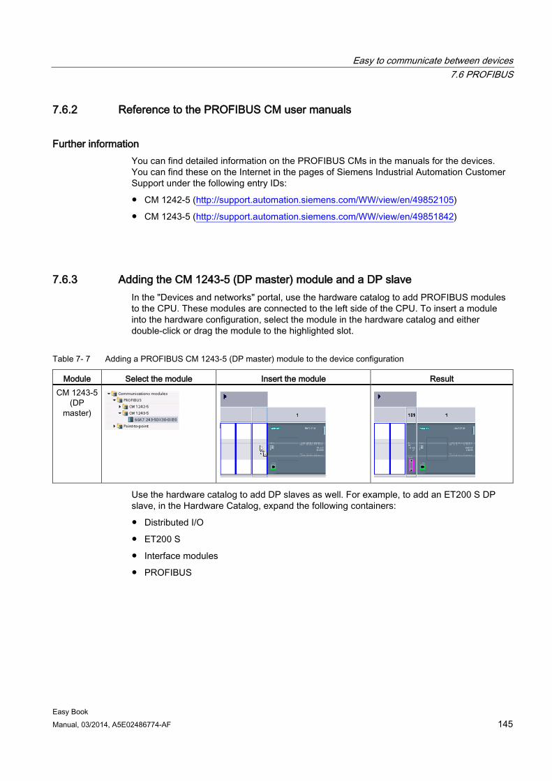
Easy to communicate between devices 7.6 PROFIBUS
Easy Book Manual, 03/2014, A5E02486774-AF 145
7.6.2 Reference to the PROFIBUS CM user manuals
Further information You can find detailed information on the PROFIBUS CMs in the manuals for the devices. You can find these on the Internet in the pages of Siemens Industrial Automation Customer Support under the following entry IDs:
● CM 1242-5 (http://support.automation.siemens.com/WW/view/en/49852105)
● CM 1243-5 (http://support.automation.siemens.com/WW/view/en/49851842)
7.6.3 Adding the CM 1243-5 (DP master) module and a DP slave In the "Devices and networks" portal, use the hardware catalog to add PROFIBUS modules to the CPU. These modules are connected to the left side of the CPU. To insert a module into the hardware configuration, select the module in the hardware catalog and either double-click or drag the module to the highlighted slot.
Table 7- 7 Adding a PROFIBUS CM 1243-5 (DP master) module to the device configuration
Module Select the module Insert the module Result CM 1243-5
(DP master)
Use the hardware catalog to add DP slaves as well. For example, to add an ET200 S DP slave, in the Hardware Catalog, expand the following containers:
● Distributed I/O
● ET200 S
● Interface modules
● PROFIBUS
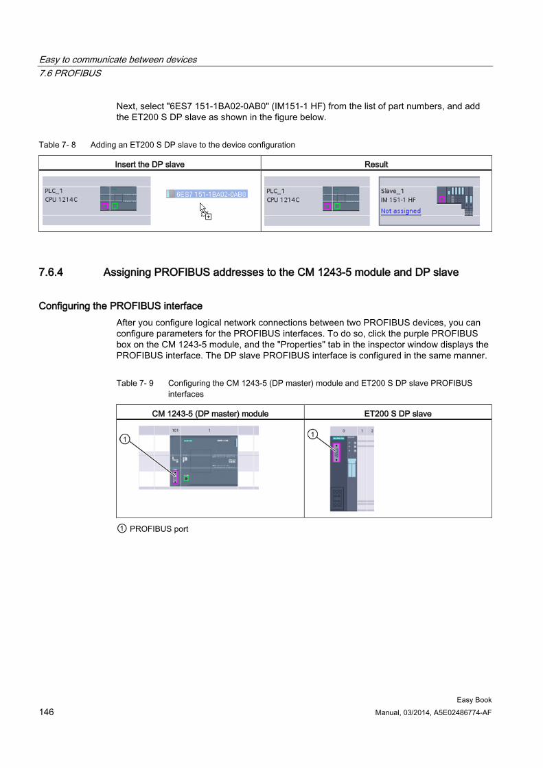
Easy to communicate between devices 7.6 PROFIBUS
Easy Book 146 Manual, 03/2014, A5E02486774-AF
Next, select "6ES7 151-1BA02-0AB0" (IM151-1 HF) from the list of part numbers, and add the ET200 S DP slave as shown in the figure below.
Table 7- 8 Adding an ET200 S DP slave to the device configuration
Insert the DP slave Result
7.6.4 Assigning PROFIBUS addresses to the CM 1243-5 module and DP slave
Configuring the PROFIBUS interface After you configure logical network connections between two PROFIBUS devices, you can configure parameters for the PROFIBUS interfaces. To do so, click the purple PROFIBUS box on the CM 1243-5 module, and the "Properties" tab in the inspector window displays the PROFIBUS interface. The DP slave PROFIBUS interface is configured in the same manner.
Table 7- 9 Configuring the CM 1243-5 (DP master) module and ET200 S DP slave PROFIBUS interfaces
CM 1243-5 (DP master) module ET200 S DP slave
① PROFIBUS port
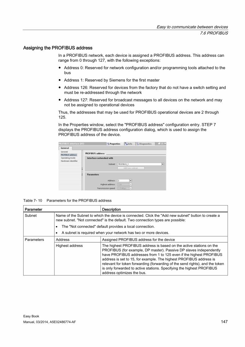
Easy to communicate between devices 7.6 PROFIBUS
Easy Book Manual, 03/2014, A5E02486774-AF 147
Assigning the PROFIBUS address In a PROFIBUS network, each device is assigned a PROFIBUS address. This address can range from 0 through 127, with the following exceptions:
● Address 0: Reserved for network configuration and/or programming tools attached to the bus
● Address 1: Reserved by Siemens for the first master
● Address 126: Reserved for devices from the factory that do not have a switch setting and must be re-addressed through the network
● Address 127: Reserved for broadcast messages to all devices on the network and may not be assigned to operational devices
Thus, the addresses that may be used for PROFIBUS operational devices are 2 through 125.
In the Properties window, select the "PROFIBUS address" configuration entry. STEP 7 displays the PROFIBUS address configuration dialog, which is used to assign the PROFIBUS address of the device.
Table 7- 10 Parameters for the PROFIBUS address
Parameter Description Subnet Name of the Subnet to which the device is connected. Click the "Add new subnet" button to create a
new subnet. "Not connected" is the default. Two connection types are possible: • The "Not connected" default provides a local connection. • A subnet is required when your network has two or more devices.
Parameters Address Assigned PROFIBUS address for the device Highest address The highest PROFIBUS address is based on the active stations on the
PROFIBUS (for example, DP master). Passive DP slaves independently have PROFIBUS addresses from 1 to 125 even if the highest PROFIBUS address is set to 15, for example. The highest PROFIBUS address is relevant for token forwarding (forwarding of the send rights), and the token is only forwarded to active stations. Specifying the highest PROFIBUS address optimizes the bus.
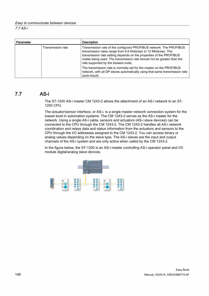
Easy to communicate between devices 7.7 AS-i
Easy Book 148 Manual, 03/2014, A5E02486774-AF
Parameter Description Transmission rate Transmission rate of the configured PROFIBUS network: The PROFIBUS
transmission rates range from 9.6 Kbits/sec to 12 Mbits/sec. The transmission rate setting depends on the properties of the PROFIBUS nodes being used. The transmission rate should not be greater than the rate supported by the slowest node. The transmission rate is normally set for the master on the PROFIBUS network, with all DP slaves automatically using that same transmission rate (auto-baud).
7.7 AS-i The S7-1200 AS-i master CM 1243-2 allows the attachment of an AS-i network to an S7-1200 CPU.
The actuator/sensor interface, or AS-i, is a single master network connection system for the lowest level in automation systems. The CM 1243-2 serves as the AS-i master for the network. Using a single AS-i cable, sensors and actuators (AS-i slave devices) can be connected to the CPU through the CM 1243-2. The CM 1243-2 handles all AS-i network coordination and relays data and status information from the actuators and sensors to the CPU through the I/O addresses assigned to the CM 1243-2. You can access binary or analog values depending on the slave type. The AS-i slaves are the input and output channels of the AS-i system and are only active when called by the CM 1243-2.
In the figure below, the S7-1200 is an AS-i master controlling AS-i operator panel and I/O module digital/analog slave devices.
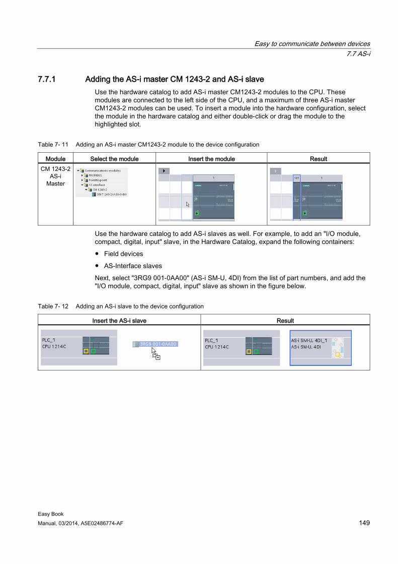
Easy to communicate between devices 7.7 AS-i
Easy Book Manual, 03/2014, A5E02486774-AF 149
7.7.1 Adding the AS-i master CM 1243-2 and AS-i slave Use the hardware catalog to add AS-i master CM1243-2 modules to the CPU. These modules are connected to the left side of the CPU, and a maximum of three AS-i master CM1243-2 modules can be used. To insert a module into the hardware configuration, select the module in the hardware catalog and either double-click or drag the module to the highlighted slot.
Table 7- 11 Adding an AS-i master CM1243-2 module to the device configuration
Module Select the module Insert the module Result CM 1243-2
AS-i Master
Use the hardware catalog to add AS-i slaves as well. For example, to add an "I/O module, compact, digital, input" slave, in the Hardware Catalog, expand the following containers:
● Field devices
● AS-Interface slaves
Next, select "3RG9 001-0AA00" (AS-i SM-U, 4DI) from the list of part numbers, and add the "I/O module, compact, digital, input" slave as shown in the figure below.
Table 7- 12 Adding an AS-i slave to the device configuration
Insert the AS-i slave Result
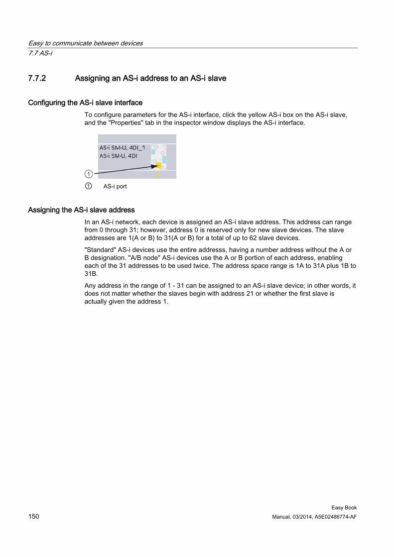
Easy to communicate between devices 7.7 AS-i
Easy Book 150 Manual, 03/2014, A5E02486774-AF
7.7.2 Assigning an AS-i address to an AS-i slave
Configuring the AS-i slave interface To configure parameters for the AS-i interface, click the yellow AS-i box on the AS-i slave, and the "Properties" tab in the inspector window displays the AS-i interface.
① AS-i port
Assigning the AS-i slave address In an AS-i network, each device is assigned an AS-i slave address. This address can range from 0 through 31; however, address 0 is reserved only for new slave devices. The slave addresses are 1(A or B) to 31(A or B) for a total of up to 62 slave devices.
"Standard" AS-i devices use the entire addresss, having a number address without the A or B designation. "A/B node" AS-i devices use the A or B portion of each address, enabling each of the 31 addresses to be used twice. The address space range is 1A to 31A plus 1B to 31B.
Any address in the range of 1 - 31 can be assigned to an AS-i slave device; in other words, it does not matter whether the slaves begin with address 21 or whether the first slave is actually given the address 1.
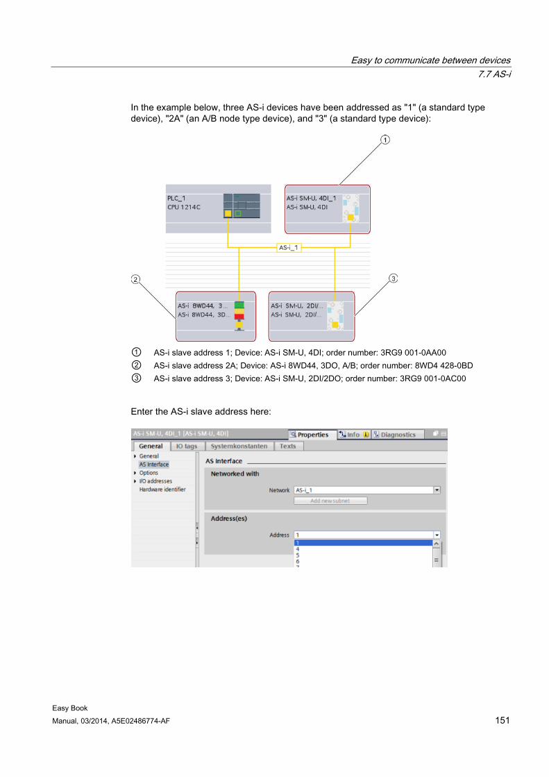
Easy to communicate between devices 7.7 AS-i
Easy Book Manual, 03/2014, A5E02486774-AF 151
In the example below, three AS-i devices have been addressed as "1" (a standard type device), "2A" (an A/B node type device), and "3" (a standard type device):
① AS-i slave address 1; Device: AS-i SM-U, 4DI; order number: 3RG9 001-0AA00 ② AS-i slave address 2A; Device: AS-i 8WD44, 3DO, A/B; order number: 8WD4 428-0BD ③ AS-i slave address 3; Device: AS-i SM-U, 2DI/2DO; order number: 3RG9 001-0AC00
Enter the AS-i slave address here:
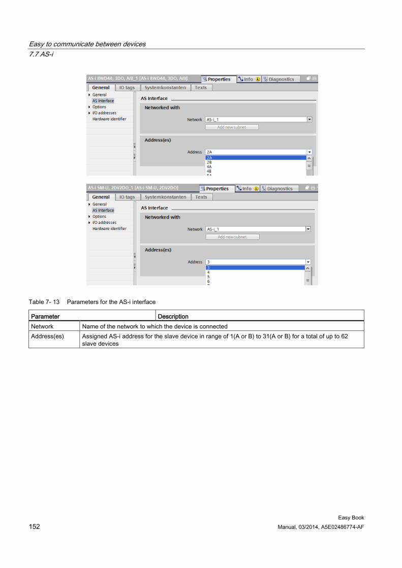
Easy to communicate between devices 7.7 AS-i
Easy Book 152 Manual, 03/2014, A5E02486774-AF
Table 7- 13 Parameters for the AS-i interface
Parameter Description Network Name of the network to which the device is connected Address(es) Assigned AS-i address for the slave device in range of 1(A or B) to 31(A or B) for a total of up to 62
slave devices
Easy to communicate between devices 7.8 S7 communication
Easy Book Manual, 03/2014, A5E02486774-AF 153
7.8 S7 communication
7.8.1 GET and PUT instructions You can use the GET and PUT instructions to communicate with S7 CPUs through PROFINET and PROFIBUS connections. This is only possible if the "Permit access with PUT/GET communication" function is activated for the partner CPU in the "Protection" property of the local CPU properties:
● Accessing data in a remote CPU: An S7-1200 CPU can only use absolute addresses in the ADDR_x input field to address variables of remote CPUs (S7-200/300/400/1200).
● Accessing data in a standard DB: An S7-1200 CPU can only use absolute addresses in the ADDR_x input field to address DB variables in a standard DB of a remote S7 CPU.
● Accessing data in an optimized DB: An S7-1200 CPU cannot access DB variables in an optimized DB of a remote S7-1200 CPU.
● Accessing data in a local CPU: An S7-1200 CPU can use either absolute or symbolic addresses as inputs to the RD_x or SD_x input fields of the GET or PUT instruction, respectively.
STEP 7 automatically creates the DB when you insert the instruction.
Note
To ensure data consistency, always evaluate when the operation has been completed (NDR = 1 for GET, or DONE = 1 for PUT) before accessing the data or initiating another read or write operation.
Note V4.0 CPU program GET/PUT operation is not automatically enabled
A V3.0 CPU program GET/PUT operation is automatically enabled in a V4.0 CPU.
However, a V4.0 CPU program GET/PUT operation in a V4.0 CPU is not automatically enabled. You must go the CPU "Device configuration", inspector window "Properties"tab, "Protection" property to enable GET/PUT access (Page 82).
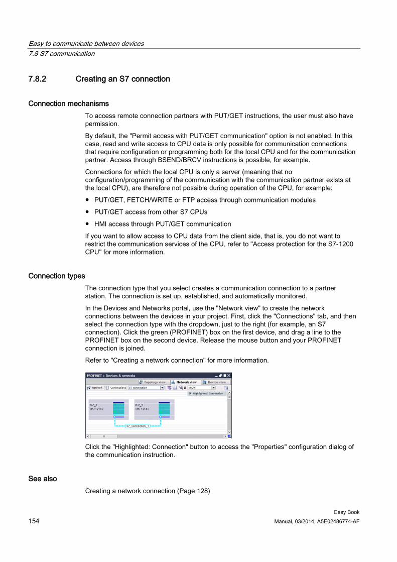
Easy to communicate between devices 7.8 S7 communication
Easy Book 154 Manual, 03/2014, A5E02486774-AF
7.8.2 Creating an S7 connection
Connection mechanisms To access remote connection partners with PUT/GET instructions, the user must also have permission.
By default, the "Permit access with PUT/GET communication" option is not enabled. In this case, read and write access to CPU data is only possible for communication connections that require configuration or programming both for the local CPU and for the communication partner. Access through BSEND/BRCV instructions is possible, for example.
Connections for which the local CPU is only a server (meaning that no configuration/programming of the communication with the communication partner exists at the local CPU), are therefore not possible during operation of the CPU, for example:
● PUT/GET, FETCH/WRITE or FTP access through communication modules
● PUT/GET access from other S7 CPUs
● HMI access through PUT/GET communication
If you want to allow access to CPU data from the client side, that is, you do not want to restrict the communication services of the CPU, refer to "Access protection for the S7-1200 CPU" for more information.
Connection types The connection type that you select creates a communication connection to a partner station. The connection is set up, established, and automatically monitored.
In the Devices and Networks portal, use the "Network view" to create the network connections between the devices in your project. First, click the "Connections" tab, and then select the connection type with the dropdown, just to the right (for example, an S7 connection). Click the green (PROFINET) box on the first device, and drag a line to the PROFINET box on the second device. Release the mouse button and your PROFINET connection is joined.
Refer to "Creating a network connection" for more information.
Click the "Highlighted: Connection" button to access the "Properties" configuration dialog of the communication instruction.
See also Creating a network connection (Page 128)
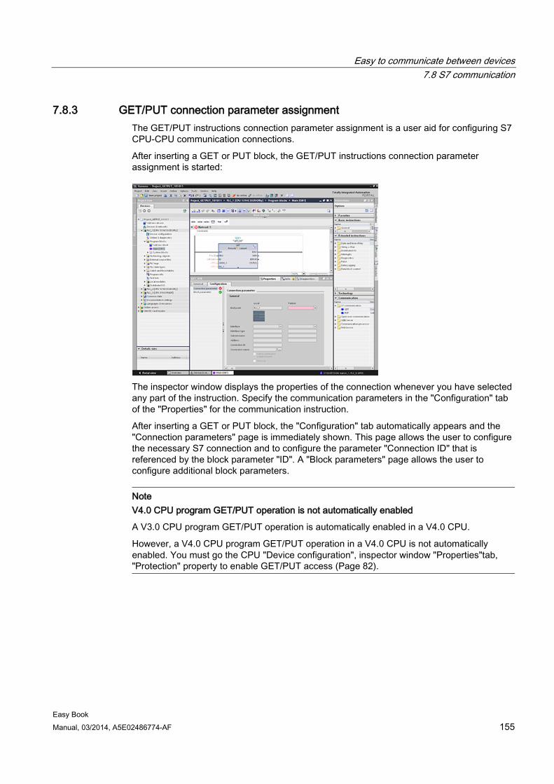
Easy to communicate between devices 7.8 S7 communication
Easy Book Manual, 03/2014, A5E02486774-AF 155
7.8.3 GET/PUT connection parameter assignment The GET/PUT instructions connection parameter assignment is a user aid for configuring S7 CPU-CPU communication connections.
After inserting a GET or PUT block, the GET/PUT instructions connection parameter assignment is started:
The inspector window displays the properties of the connection whenever you have selected any part of the instruction. Specify the communication parameters in the "Configuration" tab of the "Properties" for the communication instruction.
After inserting a GET or PUT block, the "Configuration" tab automatically appears and the "Connection parameters" page is immediately shown. This page allows the user to configure the necessary S7 connection and to configure the parameter "Connection ID" that is referenced by the block parameter "ID". A "Block parameters" page allows the user to configure additional block parameters.
Note V4.0 CPU program GET/PUT operation is not automatically enabled
A V3.0 CPU program GET/PUT operation is automatically enabled in a V4.0 CPU.
However, a V4.0 CPU program GET/PUT operation in a V4.0 CPU is not automatically enabled. You must go the CPU "Device configuration", inspector window "Properties"tab, "Protection" property to enable GET/PUT access (Page 82).
Easy to communicate between devices 7.9 GPRS
Easy Book 156 Manual, 03/2014, A5E02486774-AF
7.9 GPRS
7.9.1 Connection to a GSM network
IP-based WAN communication via GPRS Using the CP 1242-7 communications processor, the S7-1200 can be connected to GSM networks. The CP 1242-7 allows WAN communication from remote stations with a control center and inter-station communication.
Inter-station communication is possible only via a GSM network. For communication between a remote station and a control room, the control center must have a PC with Internet access.
The CP 1242-7 supports the following services for communication via the GSM network:
● GPRS (General Packet Radio Service)
The packet-oriented service for data transmission "GPRS" is handled via the GSM network.
● SMS (Short Message Service)
The CP 1242-7 can receive and send SMS messages. The communications partner can be a mobile phone or an S7-1200.
The CP 1242-7 is suitable for use in industry worldwide and supports the following frequency bands:
● 850 MHz
● 900 MHz
● 1 800 MHz
● 1 900 MHz
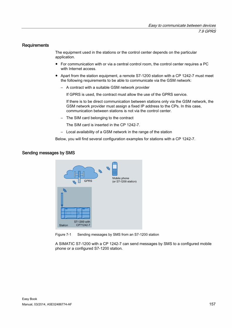
Easy to communicate between devices 7.9 GPRS
Easy Book Manual, 03/2014, A5E02486774-AF 157
Requirements The equipment used in the stations or the control center depends on the particular application.
● For communication with or via a central control room, the control center requires a PC with Internet access.
● Apart from the station equipment, a remote S7-1200 station with a CP 1242-7 must meet the following requirements to be able to communicate via the GSM network:
– A contract with a suitable GSM network provider
If GPRS is used, the contract must allow the use of the GPRS service.
If there is to be direct communication between stations only via the GSM network, the GSM network provider must assign a fixed IP address to the CPs. In this case, communication between stations is not via the control center.
– The SIM card belonging to the contract
The SIM card is inserted in the CP 1242-7.
– Local availability of a GSM network in the range of the station
Below, you will find several configuration examples for stations with a CP 1242-7.
Sending messages by SMS
Figure 7-1 Sending messages by SMS from an S7-1200 station
A SIMATIC S7-1200 with a CP 1242-7 can send messages by SMS to a configured mobile phone or a configured S7-1200 station.
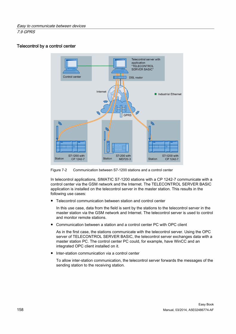
Easy to communicate between devices 7.9 GPRS
Easy Book 158 Manual, 03/2014, A5E02486774-AF
Telecontrol by a control center
Figure 7-2 Communication between S7-1200 stations and a control center
In telecontrol applications, SIMATIC S7-1200 stations with a CP 1242-7 communicate with a control center via the GSM network and the Internet. The TELECONTROL SERVER BASIC application is installed on the telecontrol server in the master station. This results in the following use cases:
● Telecontrol communication between station and control center
In this use case, data from the field is sent by the stations to the telecontrol server in the master station via the GSM network and Internet. The telecontrol server is used to control and monitor remote stations.
● Communication between a station and a control center PC with OPC client
As in the first case, the stations communicate with the telecontrol server. Using the OPC server of TELECONTROL SERVER BASIC, the telecontrol server exchanges data with a master station PC. The control center PC could, for example, have WinCC and an integrated OPC client installed on it.
● Inter-station communication via a control center
To allow inter-station communication, the telecontrol server forwards the messages of the sending station to the receiving station.
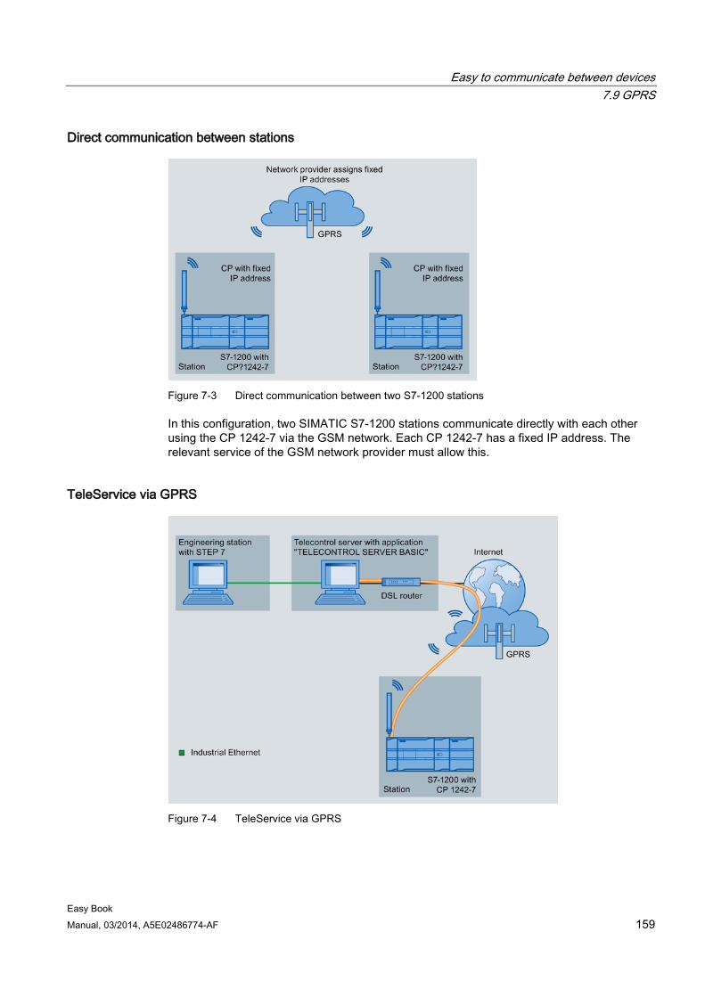
Easy to communicate between devices 7.9 GPRS
Easy Book Manual, 03/2014, A5E02486774-AF 159
Direct communication between stations
Figure 7-3 Direct communication between two S7-1200 stations
In this configuration, two SIMATIC S7-1200 stations communicate directly with each other using the CP 1242-7 via the GSM network. Each CP 1242-7 has a fixed IP address. The relevant service of the GSM network provider must allow this.
TeleService via GPRS
Figure 7-4 TeleService via GPRS
Easy to communicate between devices 7.9 GPRS
Easy Book 160 Manual, 03/2014, A5E02486774-AF
In TeleService via GPRS, an engineering station on which STEP 7 is installed communicates via the GSM network and the Internet with a SIMATIC S7-1200 station with a CP 1242-7. The connection runs via a telecontrol server that serves as an intermediary and is connected to the Internet.
The CP 1242-7 can be used for the following applications:
Telecontrol applications ● Sending messages by SMS
Via the CP 1242-7, the CPU of a remote S7-1200 station can receive SMS messages from the GSM network or send messages by SMS to a configured mobile phone or an S7-1200.
● Communication with a control center
Remote S7-1200 stations communicate via the GSM network and the Internet with a telecontrol server in the master station. For data transfer using GPRS, the "TELECONTROL SERVER BASIC" application is installed on the telecontrol server in the master station. The telecontrol server communicates with a higher-level central control system using the integrated OPC server function.
● Inter-station communication between S7-1200 stations via a GSM network
Inter-station communication between remote stations with a CP 1242-7 can be handled in two different ways:
– Indirect communication via a master station
In this configuration, a permanent secure connection between S7-1200 stations that communicate with each other and the telecontrol server is established in the master station. Communication between the stations is via the telecontrol server. The CP 1242-7 operates in "Telecontrol" mode.
– Direct communication between the stations
For direct communication between stations without the detour via the master station, SIM cards with a fixed IP address are used that allow the stations to address each other directly. The possible communications services and security functions (for example VPN) depend on what is offered by the network provider. The CP 1242-7 operates in "GPRS direct" mode.
TeleService via GPRS A TeleService connection can be established between an engineering station with STEP 7 and a remote S7-1200 station with a CP 1242-7 via the GSM network and the Internet. The connection runs from the engineering station via a telecontrol server or a TeleService gateway that acts as an intermediary forwarding frames and establishing the authorization. These PCs use the functions of the "TELECONTROL SERVER BASIC" application.
You can use the TeleService connection for the following purposes:
● Downloading configuration or program data from the STEP 7 project to the station
● Querying diagnostics data on the station
Easy to communicate between devices 7.9 GPRS
Easy Book Manual, 03/2014, A5E02486774-AF 161
Other services and functions of the CP 1242-7 ● Time-of-day synchronization of the CP via the Internet
You can set the time on the CP as follows:
– In "Telecontrol" mode, the time of day is transferred by the telecontrol server. The CP uses this to set its time.
– In "GPRS direct" mode, the CP can request the time using SNTP.
To synchronize the CPU time, you can read out the current time from the CP using a block.
● Interim buffering of messages to be sent if there are connection problems
● Logging the volume of data
The volumes of data transferred are logged and can be evaluated for specific purposes.
Configuration and module replacement To configure the module, the following configuration tool is required:
STEP 7 version V11.0 SP1 or higher
For STEP 7 V11.0 SP1, you also require support package "CP 1242-7" (HSP0003001).
For process data transfer using GPRS, use the telecontrol communications instructions in the user program of the station.
The configuration data of the CP 1242-7 is stored on the local CPU. This allows simple replacement of the CP when necessary.
You can insert up to three modules of the CP 1242-7 type per S7-1200. This, for example, allows redundant communications paths to be established.
Electrical connections ● Power supply of the CP 1242-7
The CP has a separate connection for the external 24 VDC power supply.
● Wireless interface for the GSM network
An extra antenna is required for GSM communication. This is connected via the SMA socket of the CP.
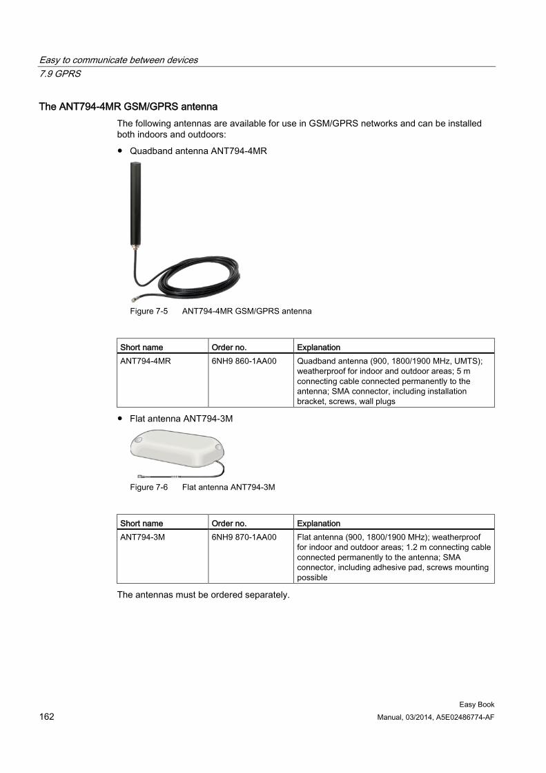
Easy to communicate between devices 7.9 GPRS
Easy Book 162 Manual, 03/2014, A5E02486774-AF
The ANT794-4MR GSM/GPRS antenna The following antennas are available for use in GSM/GPRS networks and can be installed both indoors and outdoors:
● Quadband antenna ANT794-4MR
Figure 7-5 ANT794-4MR GSM/GPRS antenna
Short name Order no. Explanation ANT794-4MR 6NH9 860-1AA00 Quadband antenna (900, 1800/1900 MHz, UMTS);
weatherproof for indoor and outdoor areas; 5 m connecting cable connected permanently to the antenna; SMA connector, including installation bracket, screws, wall plugs
● Flat antenna ANT794-3M
Figure 7-6 Flat antenna ANT794-3M
Short name Order no. Explanation ANT794-3M 6NH9 870-1AA00 Flat antenna (900, 1800/1900 MHz); weatherproof
for indoor and outdoor areas; 1.2 m connecting cable connected permanently to the antenna; SMA connector, including adhesive pad, screws mounting possible
The antennas must be ordered separately.
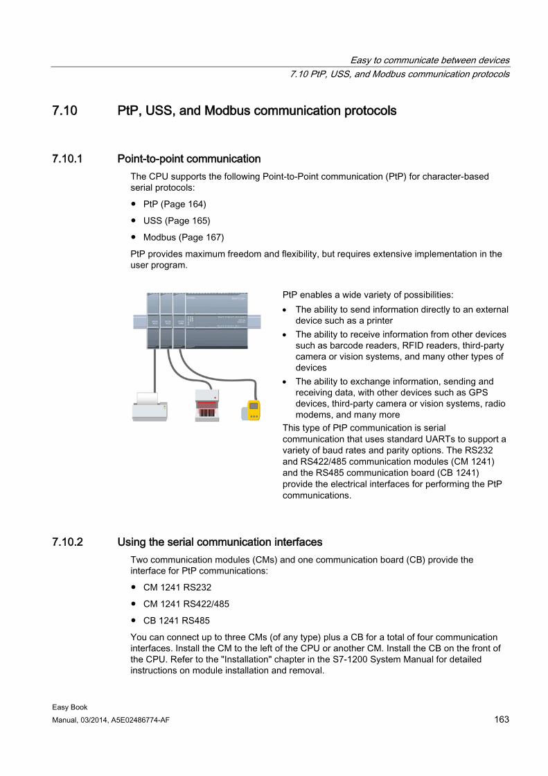
Easy to communicate between devices 7.10 PtP, USS, and Modbus communication protocols
Easy Book Manual, 03/2014, A5E02486774-AF 163
7.10 PtP, USS, and Modbus communication protocols
7.10.1 Point-to-point communication The CPU supports the following Point-to-Point communication (PtP) for character-based serial protocols:
● PtP (Page 164)
● USS (Page 165)
● Modbus (Page 167)
PtP provides maximum freedom and flexibility, but requires extensive implementation in the user program.
PtP enables a wide variety of possibilities: • The ability to send information directly to an external
device such as a printer • The ability to receive information from other devices
such as barcode readers, RFID readers, third-party camera or vision systems, and many other types of devices
• The ability to exchange information, sending and receiving data, with other devices such as GPS devices, third-party camera or vision systems, radio modems, and many more
This type of PtP communication is serial communication that uses standard UARTs to support a variety of baud rates and parity options. The RS232 and RS422/485 communication modules (CM 1241) and the RS485 communication board (CB 1241) provide the electrical interfaces for performing the PtP communications.
7.10.2 Using the serial communication interfaces Two communication modules (CMs) and one communication board (CB) provide the interface for PtP communications:
● CM 1241 RS232
● CM 1241 RS422/485
● CB 1241 RS485
You can connect up to three CMs (of any type) plus a CB for a total of four communication interfaces. Install the CM to the left of the CPU or another CM. Install the CB on the front of the CPU. Refer to the "Installation" chapter in the S7-1200 System Manual for detailed instructions on module installation and removal.
Easy to communicate between devices 7.10 PtP, USS, and Modbus communication protocols
Easy Book 164 Manual, 03/2014, A5E02486774-AF
The serial communication interfaces have the following characteristics:
● Have an isolated port
● Support Point-to-Point protocols
● Are configured and programmed through the point-to-point communication processor instructions
● Display transmit and receive activity by means of LEDs
● Display a diagnostic LED (CMs only)
● Are powered by the CPU: No external power connection is needed.
Refer to the technical specifications for communication interfaces.
LED indicators The communication modules have three LED indicators:
● Diagnostic LED (DIAG): This LED flashes red until it is addressed by the CPU. After the CPU powers up, it checks for CMs and addresses them. The diagnostic LED begins to flash green. This means that the CPU has addressed the CM, but has not yet provided the configuration to it. The CPU downloads the configuration to the configured CMs when the program is downloaded to the CPU. After a download to the CPU, the diagnostic LED on the communication module should be a steady green.
● Transmit LED (Tx): The transmit LED illuminates when data is being transmitted out the communication port.
● Receive LED (Rx): This LED illuminates when data is being received by the communication port.
The communication board provides transmit (TxD) and receive (RxD) LEDs. It has no diagnostic LED.
7.10.3 PtP instructions The PORT_CFG, SEND_CFG, and RCV_CFG instructions allow you to change the configuration from your user program.
● PORT_CFG changes the port parameters such as baud rate.
● SEND_CFG changes the configuration of serial transmission parameters.
● RCV_CFG changes the configuration of serial receiver parameters in a communication port. This instruction configures the conditions that signal the start and end of a received message. Messages that satisfy these conditions will be received by the RCV_PTP instruction.
Easy to communicate between devices 7.10 PtP, USS, and Modbus communication protocols
Easy Book Manual, 03/2014, A5E02486774-AF 165
The dynamic configuration changes are not permanently stored in the CPU. After a power cycle, the initial static configuration from the device configuration will be used.
The SEND_PTP, RCV_PTP, and RCV_RST instructions control the PtP communication:
● SEND_PTP transfers the specified buffer to the CM or CB. The CPU continues to execute the user program while the module sends the data at the specified baud rate.
● RCV_PTP checks for messages that have been received in the CM or CB. If a message is available, it will be transferred to the CPU.
● The RCV_RST resets the receive buffer.
Each CM or CB can buffer up to a maximum of 1K bytes. This buffer can be allocated across multiple received messages.
The SGN_SET and SGN_GET are valid only for the RS232 CM. Use these instructions to read or set the RS232 communication signals.
7.10.4 USS instructions S7-1200 supports the USS protocol and provides instructions that are specifically designed for communicating with drives over the RS485 port of a CM or a CB. You can control the physical drive and the read/write drive parameters with the USS instructions. Each RS485 CM or CB supports a maximum of 16 drives.
● The USS_PORT instruction handles actual communication between the CPU and all the drives attached to one CM or CB. Insert a different USS_PORT instruction for each CM or CB in your application. Ensure that the user program executes the USS_PORT instruction fast enough to prevent a communication timeout by the drive. Use the USS_PORT instruction in a program cycle or any interrupt OB.
● The USS_DRV instruction accesses a specified drive on the USS network. The input and output parameters of the USS_DRV instruction are the status and controls for the drive. If there are 16 drives on the network, your program must have at least 16 USS_DRV instructions, with one instruction for each drive.
Ensure that the CPU executes the USS_DRV instruction at the rate that is required to control the functions of the drive. Use the USS_DRV instruction only in a program cycle OB.
● The USS_RPM and USS_WPM instructions read and write the operating parameters of the remote drive. These parameters control the internal operation of the drive. See the drive manual for the definition of these parameters.
Your program can contain as many of these instructions as necessary. However, only one read or write request can be active for any one drive at any given time. Use the USS_RPM and USS_WPM instructions only in a program cycle OB.
An instance DB contains temporary storage and buffers for all of the drives on the USS network connected to each CM or CB. The USS instructions for a drive use the instance DB to share the information.
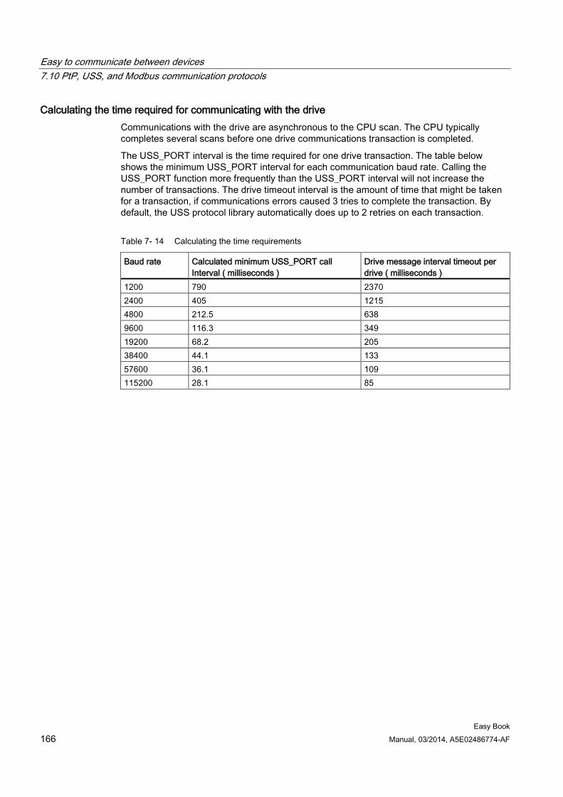
Easy to communicate between devices 7.10 PtP, USS, and Modbus communication protocols
Easy Book 166 Manual, 03/2014, A5E02486774-AF
Calculating the time required for communicating with the drive Communications with the drive are asynchronous to the CPU scan. The CPU typically completes several scans before one drive communications transaction is completed.
The USS_PORT interval is the time required for one drive transaction. The table below shows the minimum USS_PORT interval for each communication baud rate. Calling the USS_PORT function more frequently than the USS_PORT interval will not increase the number of transactions. The drive timeout interval is the amount of time that might be taken for a transaction, if communications errors caused 3 tries to complete the transaction. By default, the USS protocol library automatically does up to 2 retries on each transaction.
Table 7- 14 Calculating the time requirements
Baud rate Calculated minimum USS_PORT call Interval ( milliseconds )
Drive message interval timeout per drive ( milliseconds )
1200 790 2370 2400 405 1215 4800 212.5 638 9600 116.3 349 19200 68.2 205 38400 44.1 133 57600 36.1 109 115200 28.1 85
Easy to communicate between devices 7.10 PtP, USS, and Modbus communication protocols
Easy Book Manual, 03/2014, A5E02486774-AF 167
7.10.5 Modbus instructions The CPU supports Modbus communication over different networks:
● Modbus RTU (Remote Terminal Unit) is a standard network communication protocol that uses the RS232 or RS485 electrical connection for serial data transfer between Modbus network devices. You can add PtP (Point to Point) network ports to a CPU with a RS232 or RS485 CM or a RS485 CB.
Modbus RTU uses a master/slave network where all communications are initiated by a single Master device and slaves can only respond to a master’s request. The master sends a request to one slave address and only that slave address responds to the command.
● Modbus TCP (Transmission Control Protocol) is a standard network communication protocol that uses the PROFINET connector on the CPU for TCP/IP communication. No additional communication hardware module is required.
Modbus TCP uses client-server connections as a Modbus communication path. Multiple client-server connections may exist, in addition to the connection between STEP 7 and the CPU. Mixed client and server connections are supported up to the maximum number of connections allowed by the CPU. Each MB_SERVER connection must use a unique instance DB and IP port number. Only 1 connection per IP port is supported. Each MB_SERVER (with its unique instance DB and IP port) must be executed individually for each connection.
WARNING
If an attacker can physically access your networks, the attacker can possibly read and write data.
The TIA Portal, the CPU, and HMIs (except HMIs using GET/PUT) use secure communication that protects against replay and "man-in-the-middle" attacks. Once communication is enabled, the exchange of signed messages takes place in clear text which allows an attacker to read data, but protects against unauthorized writing of data. The TIA Portal, not the communication process, encrypts the data of know-how protected blocks.
All other forms of communication (I/O exchange through PROFIBUS, PROFINET, AS-i, or other I/O bus, GET/PUT, T-Block, and communication modules (CM)) have no security features. You must protect these forms of communication by limiting physical access. If an attacker can physically access your networks utilizing these forms of communication, the attacker can possibly read and write data.
For security information and recommendations, please see our "Operational Guidelines for Industrial Security" on the Service and Support site: www.industry.siemens.com/topics/global/en/industrial-security/Documents/operational_guidelines_industrial_security_en.pdf (http://www.industry.siemens.com/topics/global/en/industrial-security/Documents/operational_guidelines_industrial_security_en.pdf)
Note
Modbus TCP will only operate correctly with CPU firmware release V1.02 or later. An attempt to execute the Modbus instructions on an earlier firmware version will result in an error.
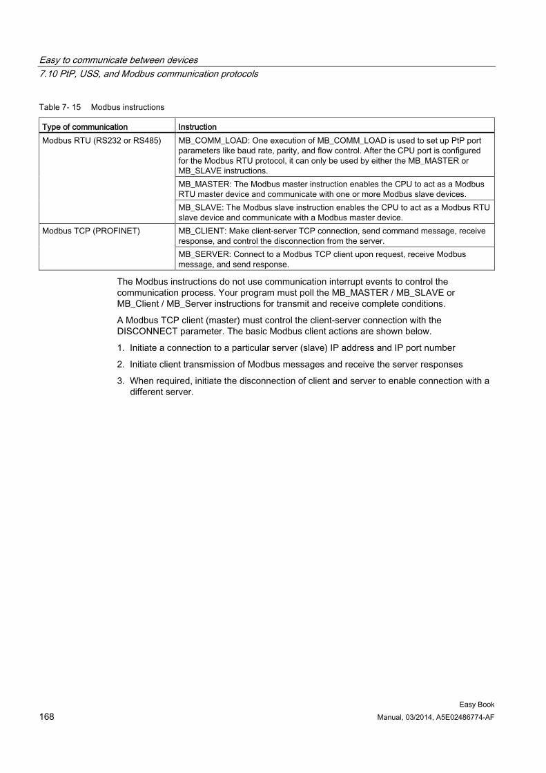
Easy to communicate between devices 7.10 PtP, USS, and Modbus communication protocols
Easy Book 168 Manual, 03/2014, A5E02486774-AF
Table 7- 15 Modbus instructions
Type of communication Instruction Modbus RTU (RS232 or RS485) MB_COMM_LOAD: One execution of MB_COMM_LOAD is used to set up PtP port
parameters like baud rate, parity, and flow control. After the CPU port is configured for the Modbus RTU protocol, it can only be used by either the MB_MASTER or MB_SLAVE instructions. MB_MASTER: The Modbus master instruction enables the CPU to act as a Modbus RTU master device and communicate with one or more Modbus slave devices. MB_SLAVE: The Modbus slave instruction enables the CPU to act as a Modbus RTU slave device and communicate with a Modbus master device.
Modbus TCP (PROFINET) MB_CLIENT: Make client-server TCP connection, send command message, receive response, and control the disconnection from the server. MB_SERVER: Connect to a Modbus TCP client upon request, receive Modbus message, and send response.
The Modbus instructions do not use communication interrupt events to control the communication process. Your program must poll the MB_MASTER / MB_SLAVE or MB_Client / MB_Server instructions for transmit and receive complete conditions.
A Modbus TCP client (master) must control the client-server connection with the DISCONNECT parameter. The basic Modbus client actions are shown below.
1. Initiate a connection to a particular server (slave) IP address and IP port number
2. Initiate client transmission of Modbus messages and receive the server responses
3. When required, initiate the disconnection of client and server to enable connection with a different server.
Easy Book Manual, 03/2014, A5E02486774-AF 169
PID is easy 8
STEP 7 provides the following PID instructions for the S7-1200 CPU:
● The PID_Compact instruction is used to control technical processes with continuous input- and output variables.
● The PID_3Step instruction is used to control motor-actuated devices, such as valves that require discrete signals for open- and close actuation.
Note
Changes that you make to the PID configuration and download in RUN do not take effect until the CPU transitions from STOP to RUN mode. Changes that you make in the "PID parameters" dialog using the "Start value control" take effect immediately.
Both PID instructions (PID_3Step and PID_Compact) can calculate the P-, I-, and D-components during startup (if configured for "pre-tuning"). You can also configure the instruction for "fine tuning" to allow you to optimize the parameters. You do not need to manually determine the parameters.
Note Execute the PID instruction at constant intervals of the sampling time (preferably in a cyclic OB).
Because the PID loop needs a certain time to respond to changes of the control value, do not calculate the output value in every cycle. Do not execute the PID instruction in the main program cycle OB (such as OB 1).
The sampling time of the PID algorithm represents the time between two calculations of the output value (control value). The output value is calculated during self-tuning and rounded to a multiple of the cycle time. All other functions of PID instruction are executed at every call.
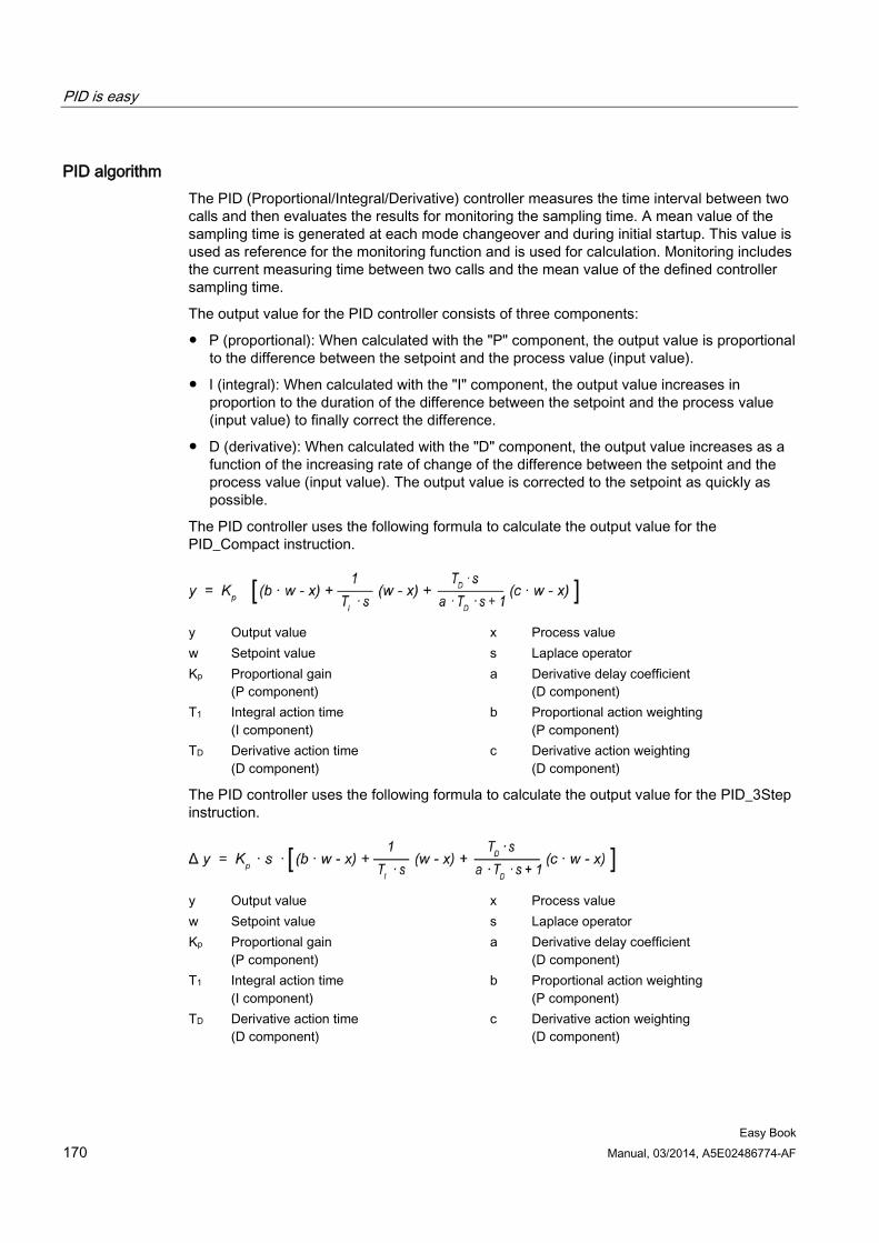
PID is easy
Easy Book 170 Manual, 03/2014, A5E02486774-AF
PID algorithm The PID (Proportional/Integral/Derivative) controller measures the time interval between two calls and then evaluates the results for monitoring the sampling time. A mean value of the sampling time is generated at each mode changeover and during initial startup. This value is used as reference for the monitoring function and is used for calculation. Monitoring includes the current measuring time between two calls and the mean value of the defined controller sampling time.
The output value for the PID controller consists of three components:
● P (proportional): When calculated with the "P" component, the output value is proportional to the difference between the setpoint and the process value (input value).
● I (integral): When calculated with the "I" component, the output value increases in proportion to the duration of the difference between the setpoint and the process value (input value) to finally correct the difference.
● D (derivative): When calculated with the "D" component, the output value increases as a function of the increasing rate of change of the difference between the setpoint and the process value (input value). The output value is corrected to the setpoint as quickly as possible.
The PID controller uses the following formula to calculate the output value for the PID_Compact instruction.
y Output value x Process value w Setpoint value s Laplace operator Kp Proportional gain
(P component) a Derivative delay coefficient
(D component) T1 Integral action time
(I component) b Proportional action weighting
(P component) TD Derivative action time
(D component) c Derivative action weighting
(D component)
The PID controller uses the following formula to calculate the output value for the PID_3Step instruction.
y Output value x Process value w Setpoint value s Laplace operator Kp Proportional gain
(P component) a Derivative delay coefficient
(D component) T1 Integral action time
(I component) b Proportional action weighting
(P component) TD Derivative action time
(D component) c Derivative action weighting
(D component)
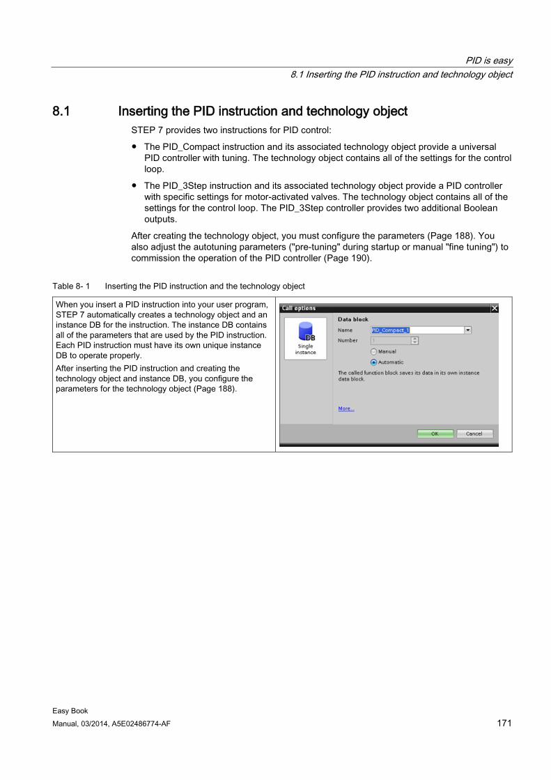
PID is easy 8.1 Inserting the PID instruction and technology object
Easy Book Manual, 03/2014, A5E02486774-AF 171
8.1 Inserting the PID instruction and technology object STEP 7 provides two instructions for PID control:
● The PID_Compact instruction and its associated technology object provide a universal PID controller with tuning. The technology object contains all of the settings for the control loop.
● The PID_3Step instruction and its associated technology object provide a PID controller with specific settings for motor-activated valves. The technology object contains all of the settings for the control loop. The PID_3Step controller provides two additional Boolean outputs.
After creating the technology object, you must configure the parameters (Page 188). You also adjust the autotuning parameters ("pre-tuning" during startup or manual "fine tuning") to commission the operation of the PID controller (Page 190).
Table 8- 1 Inserting the PID instruction and the technology object
When you insert a PID instruction into your user program, STEP 7 automatically creates a technology object and an instance DB for the instruction. The instance DB contains all of the parameters that are used by the PID instruction. Each PID instruction must have its own unique instance DB to operate properly. After inserting the PID instruction and creating the technology object and instance DB, you configure the parameters for the technology object (Page 188).
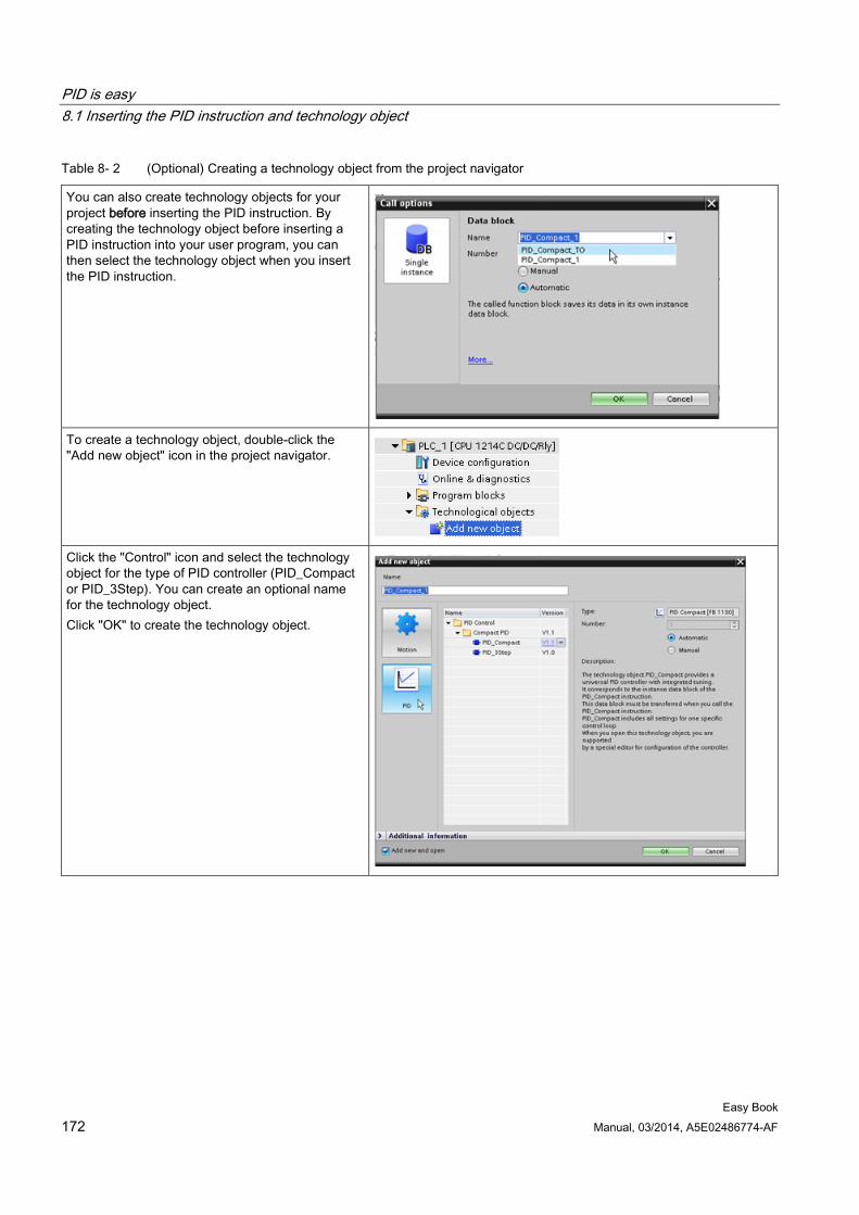
PID is easy 8.1 Inserting the PID instruction and technology object
Easy Book 172 Manual, 03/2014, A5E02486774-AF
Table 8- 2 (Optional) Creating a technology object from the project navigator
You can also create technology objects for your project before inserting the PID instruction. By creating the technology object before inserting a PID instruction into your user program, you can then select the technology object when you insert the PID instruction.
To create a technology object, double-click the "Add new object" icon in the project navigator.
Click the "Control" icon and select the technology object for the type of PID controller (PID_Compact or PID_3Step). You can create an optional name for the technology object. Click "OK" to create the technology object.
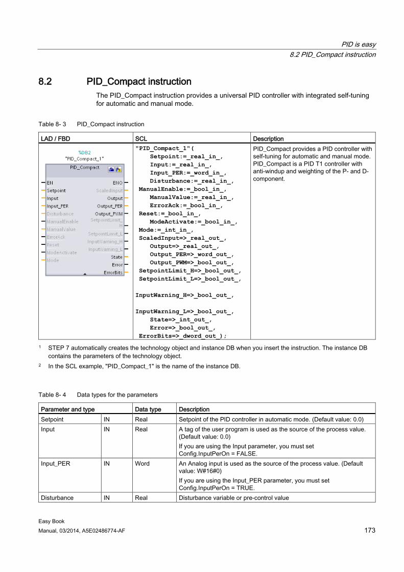
PID is easy 8.2 PID_Compact instruction
Easy Book Manual, 03/2014, A5E02486774-AF 173
8.2 PID_Compact instruction The PID_Compact instruction provides a universal PID controller with integrated self-tuning for automatic and manual mode.
Table 8- 3 PID_Compact instruction
LAD / FBD SCL Description
"PID_Compact_1"( Setpoint:=_real_in_, Input:=_real_in_, Input_PER:=_word_in_, Disturbance:=_real_in_, ManualEnable:=_bool_in_, ManualValue:=_real_in_, ErrorAck:=_bool_in_, Reset:=_bool_in_, ModeActivate:=_bool_in_, Mode:=_int_in_, ScaledInput=>_real_out_, Output=>_real_out_, Output_PER=>_word_out_, Output_PWM=>_bool_out_, SetpointLimit_H=>_bool_out_, SetpointLimit_L=>_bool_out_, InputWarning_H=>_bool_out_, InputWarning_L=>_bool_out_, State=>_int_out_, Error=>_bool_out_, ErrorBits=>_dword_out_);
PID_Compact provides a PID controller with self-tuning for automatic and manual mode. PID_Compact is a PID T1 controller with anti-windup and weighting of the P- and D- component.
1 STEP 7 automatically creates the technology object and instance DB when you insert the instruction. The instance DB contains the parameters of the technology object.
2 In the SCL example, "PID_Compact_1" is the name of the instance DB.
Table 8- 4 Data types for the parameters
Parameter and type Data type Description Setpoint IN Real Setpoint of the PID controller in automatic mode. (Default value: 0.0) Input IN Real A tag of the user program is used as the source of the process value.
(Default value: 0.0) If you are using the Input parameter, you must set Config.InputPerOn = FALSE.
Input_PER IN Word An Analog input is used as the source of the process value. (Default value: W#16#0) If you are using the Input_PER parameter, you must set Config.InputPerOn = TRUE.
Disturbance IN Real Disturbance variable or pre-control value
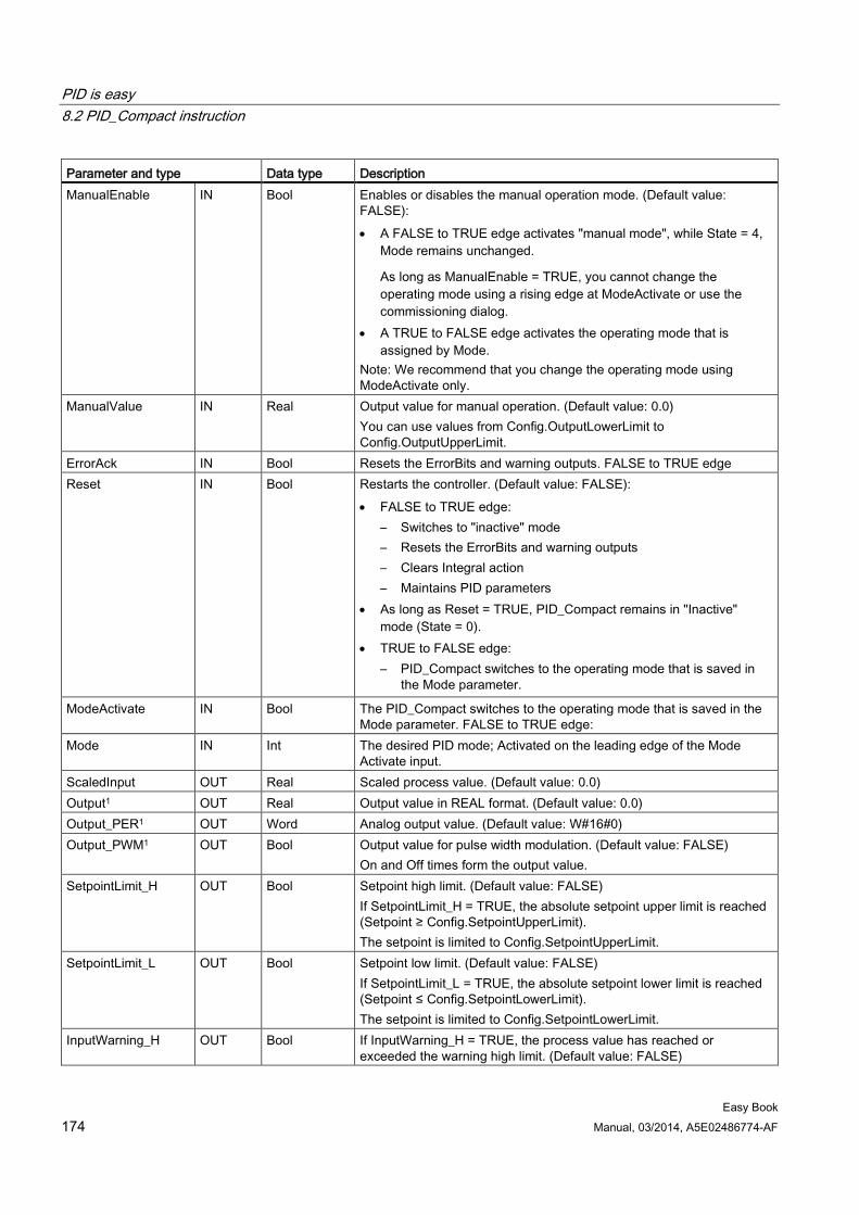
PID is easy 8.2 PID_Compact instruction
Easy Book 174 Manual, 03/2014, A5E02486774-AF
Parameter and type Data type Description ManualEnable IN Bool Enables or disables the manual operation mode. (Default value:
FALSE): • A FALSE to TRUE edge activates "manual mode", while State = 4,
Mode remains unchanged.
As long as ManualEnable = TRUE, you cannot change the operating mode using a rising edge at ModeActivate or use the commissioning dialog.
• A TRUE to FALSE edge activates the operating mode that is assigned by Mode.
Note: We recommend that you change the operating mode using ModeActivate only.
ManualValue IN Real Output value for manual operation. (Default value: 0.0) You can use values from Config.OutputLowerLimit to Config.OutputUpperLimit.
ErrorAck IN Bool Resets the ErrorBits and warning outputs. FALSE to TRUE edge Reset IN Bool Restarts the controller. (Default value: FALSE):
• FALSE to TRUE edge: – Switches to "inactive" mode – Resets the ErrorBits and warning outputs – Clears Integral action – Maintains PID parameters
• As long as Reset = TRUE, PID_Compact remains in "Inactive" mode (State = 0).
• TRUE to FALSE edge: – PID_Compact switches to the operating mode that is saved in
the Mode parameter.
ModeActivate IN Bool The PID_Compact switches to the operating mode that is saved in the Mode parameter. FALSE to TRUE edge:
Mode IN Int The desired PID mode; Activated on the leading edge of the Mode Activate input.
ScaledInput OUT Real Scaled process value. (Default value: 0.0) Output1 OUT Real Output value in REAL format. (Default value: 0.0) Output_PER1 OUT Word Analog output value. (Default value: W#16#0) Output_PWM1 OUT Bool Output value for pulse width modulation. (Default value: FALSE)
On and Off times form the output value. SetpointLimit_H OUT Bool Setpoint high limit. (Default value: FALSE)
If SetpointLimit_H = TRUE, the absolute setpoint upper limit is reached (Setpoint ≥ Config.SetpointUpperLimit). The setpoint is limited to Config.SetpointUpperLimit.
SetpointLimit_L OUT Bool Setpoint low limit. (Default value: FALSE) If SetpointLimit_L = TRUE, the absolute setpoint lower limit is reached (Setpoint ≤ Config.SetpointLowerLimit). The setpoint is limited to Config.SetpointLowerLimit.
InputWarning_H OUT Bool If InputWarning_H = TRUE, the process value has reached or exceeded the warning high limit. (Default value: FALSE)
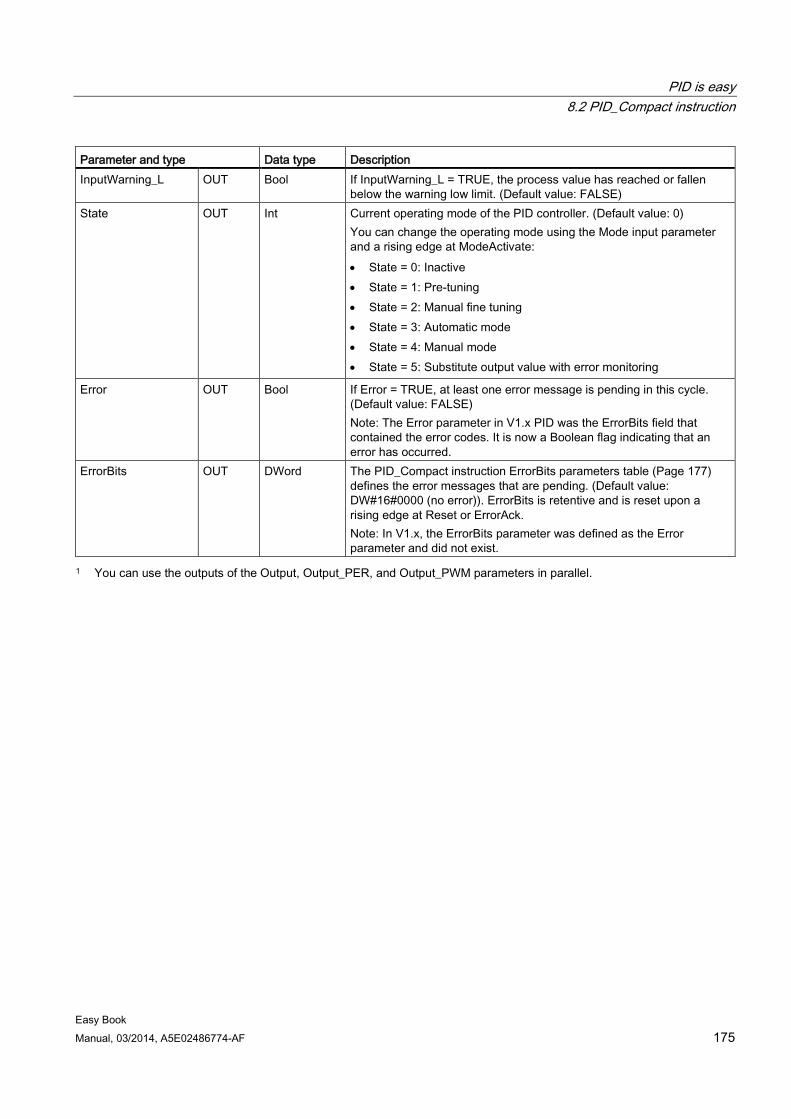
PID is easy 8.2 PID_Compact instruction
Easy Book Manual, 03/2014, A5E02486774-AF 175
Parameter and type Data type Description InputWarning_L OUT Bool If InputWarning_L = TRUE, the process value has reached or fallen
below the warning low limit. (Default value: FALSE) State OUT Int Current operating mode of the PID controller. (Default value: 0)
You can change the operating mode using the Mode input parameter and a rising edge at ModeActivate: • State = 0: Inactive • State = 1: Pre-tuning • State = 2: Manual fine tuning • State = 3: Automatic mode • State = 4: Manual mode • State = 5: Substitute output value with error monitoring
Error OUT Bool If Error = TRUE, at least one error message is pending in this cycle. (Default value: FALSE) Note: The Error parameter in V1.x PID was the ErrorBits field that contained the error codes. It is now a Boolean flag indicating that an error has occurred.
ErrorBits OUT DWord The PID_Compact instruction ErrorBits parameters table (Page 177) defines the error messages that are pending. (Default value: DW#16#0000 (no error)). ErrorBits is retentive and is reset upon a rising edge at Reset or ErrorAck. Note: In V1.x, the ErrorBits parameter was defined as the Error parameter and did not exist.
1 You can use the outputs of the Output, Output_PER, and Output_PWM parameters in parallel.
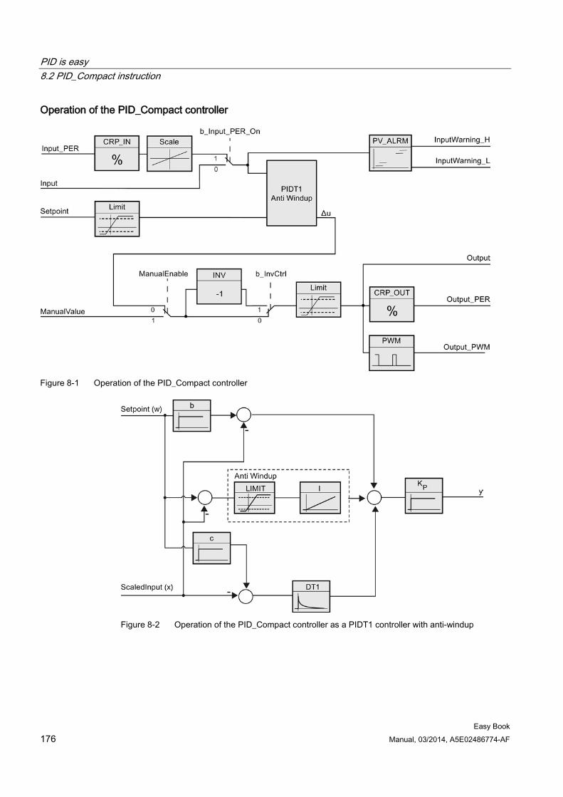
PID is easy 8.2 PID_Compact instruction
Easy Book 176 Manual, 03/2014, A5E02486774-AF
Operation of the PID_Compact controller
Figure 8-1 Operation of the PID_Compact controller
Figure 8-2 Operation of the PID_Compact controller as a PIDT1 controller with anti-windup
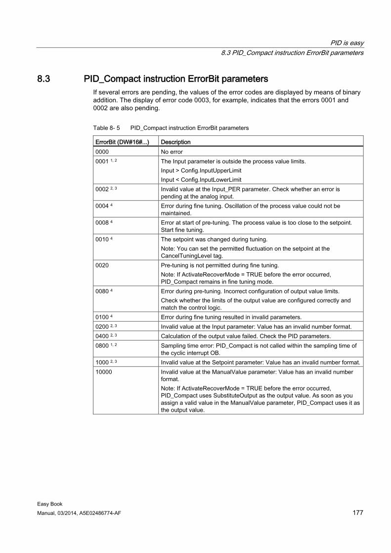
PID is easy 8.3 PID_Compact instruction ErrorBit parameters
Easy Book Manual, 03/2014, A5E02486774-AF 177
8.3 PID_Compact instruction ErrorBit parameters If several errors are pending, the values of the error codes are displayed by means of binary addition. The display of error code 0003, for example, indicates that the errors 0001 and 0002 are also pending.
Table 8- 5 PID_Compact instruction ErrorBit parameters
ErrorBit (DW#16#...) Description 0000 No error 0001 1, 2 The Input parameter is outside the process value limits.
Input > Config.InputUpperLimit Input < Config.InputLowerLimit
0002 2, 3 Invalid value at the Input_PER parameter. Check whether an error is pending at the analog input.
0004 4 Error during fine tuning. Oscillation of the process value could not be maintained.
0008 4 Error at start of pre-tuning. The process value is too close to the setpoint. Start fine tuning.
0010 4 The setpoint was changed during tuning. Note: You can set the permitted fluctuation on the setpoint at the CancelTuningLevel tag.
0020 Pre-tuning is not permitted during fine tuning. Note: If ActivateRecoverMode = TRUE before the error occurred, PID_Compact remains in fine tuning mode.
0080 4 Error during pre-tuning. Incorrect configuration of output value limits. Check whether the limits of the output value are configured correctly and match the control logic.
0100 4 Error during fine tuning resulted in invalid parameters. 0200 2, 3 Invalid value at the Input parameter: Value has an invalid number format. 0400 2, 3 Calculation of the output value failed. Check the PID parameters. 0800 1, 2 Sampling time error: PID_Compact is not called within the sampling time of
the cyclic interrupt OB. 1000 2, 3 Invalid value at the Setpoint parameter: Value has an invalid number format. 10000 Invalid value at the ManualValue parameter: Value has an invalid number
format. Note: If ActivateRecoverMode = TRUE before the error occurred, PID_Compact uses SubstituteOutput as the output value. As soon as you assign a valid value in the ManualValue parameter, PID_Compact uses it as the output value.
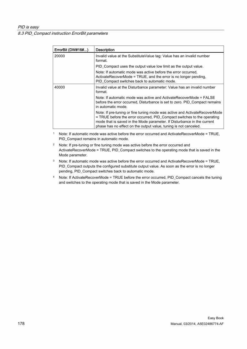
PID is easy 8.3 PID_Compact instruction ErrorBit parameters
Easy Book 178 Manual, 03/2014, A5E02486774-AF
ErrorBit (DW#16#...) Description 20000 Invalid value at the SubstituteValue tag: Value has an invalid number
format. PID_Compact uses the output value low limit as the output value. Note: If automatic mode was active before the error occurred, ActivateRecoverMode = TRUE, and the error is no longer pending, PID_Compact switches back to automatic mode.
40000 Invalid value at the Disturbance parameter: Value has an invalid number format. Note: If automatic mode was active and ActivateRecoverMode = FALSE before the error occurred, Disturbance is set to zero. PID_Compact remains in automatic mode. Note: If pre-tuning or fine tuning mode was active and ActivateRecoverMode = TRUE before the error occurred, PID_Compact switches to the operating mode that is saved in the Mode parameter. If Disturbance in the current phase has no effect on the output value, tuning is not canceled.
1 Note: If automatic mode was active before the error occurred and ActivateRecoverMode = TRUE, PID_Compact remains in automatic mode.
2 Note: If pre-tuning or fine tuning mode was active before the error occurred and ActivateRecoverMode = TRUE, PID_Compact switches to the operating mode that is saved in the Mode parameter.
3 Note: If automatic mode was active before the error occurred and ActivateRecoverMode = TRUE, PID_Compact outputs the configured substitute output value. As soon as the error is no longer pending, PID_Compact switches back to automatic mode.
4 Note: If ActivateRecoverMode = TRUE before the error occurred, PID_Compact cancels the tuning and switches to the operating mode that is saved in the Mode parameter.
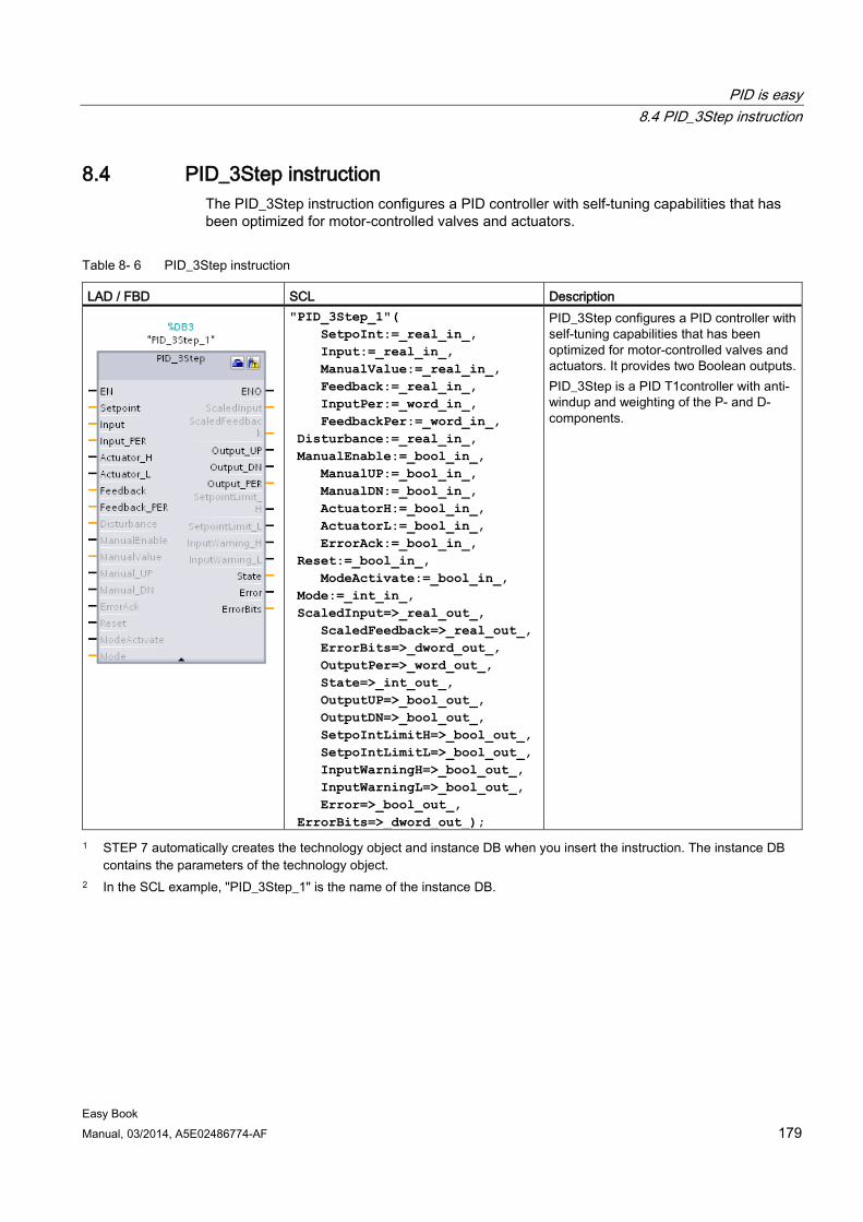
PID is easy 8.4 PID_3Step instruction
Easy Book Manual, 03/2014, A5E02486774-AF 179
8.4 PID_3Step instruction The PID_3Step instruction configures a PID controller with self-tuning capabilities that has been optimized for motor-controlled valves and actuators.
Table 8- 6 PID_3Step instruction
LAD / FBD SCL Description
"PID_3Step_1"( SetpoInt:=_real_in_, Input:=_real_in_, ManualValue:=_real_in_, Feedback:=_real_in_, InputPer:=_word_in_, FeedbackPer:=_word_in_, Disturbance:=_real_in_, ManualEnable:=_bool_in_, ManualUP:=_bool_in_, ManualDN:=_bool_in_, ActuatorH:=_bool_in_, ActuatorL:=_bool_in_, ErrorAck:=_bool_in_, Reset:=_bool_in_, ModeActivate:=_bool_in_, Mode:=_int_in_, ScaledInput=>_real_out_, ScaledFeedback=>_real_out_, ErrorBits=>_dword_out_, OutputPer=>_word_out_, State=>_int_out_, OutputUP=>_bool_out_, OutputDN=>_bool_out_, SetpoIntLimitH=>_bool_out_, SetpoIntLimitL=>_bool_out_, InputWarningH=>_bool_out_, InputWarningL=>_bool_out_, Error=>_bool_out_, ErrorBits=>_dword_out_);
PID_3Step configures a PID controller with self-tuning capabilities that has been optimized for motor-controlled valves and actuators. It provides two Boolean outputs. PID_3Step is a PID T1controller with anti-windup and weighting of the P- and D-components.
1 STEP 7 automatically creates the technology object and instance DB when you insert the instruction. The instance DB contains the parameters of the technology object.
2 In the SCL example, "PID_3Step_1" is the name of the instance DB.
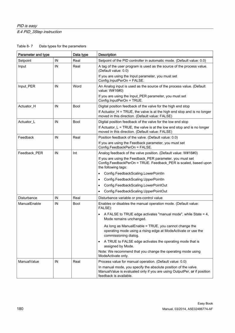
PID is easy 8.4 PID_3Step instruction
Easy Book 180 Manual, 03/2014, A5E02486774-AF
Table 8- 7 Data types for the parameters
Parameter and type Data type Description Setpoint IN Real Setpoint of the PID controller in automatic mode. (Default value: 0.0) Input IN Real A tag of the user program is used as the source of the process value.
(Default value: 0.0) If you are using the Input parameter, you must set Config.InputPerOn = FALSE.
Input_PER IN Word An Analog input is used as the source of the process value. (Default value: W#16#0) If you are using the Input_PER parameter, you must set Config.InputPerOn = TRUE.
Actuator_H IN Bool Digital position feedback of the valve for the high end stop If Actuator_H = TRUE, the valve is at the high end stop and is no longer moved in this direction. (Default value: FALSE)
Actuator_L IN Bool Digital position feedback of the valve for the low end stop If Actuator_L = TRUE, the valve is at the low end stop and is no longer moved in this direction. (Default value: FALSE)
Feedback IN Real Position feedback of the valve. (Default value: 0.0) If you are using the Feedback parameter, you must set Config.FeedbackPerOn = FALSE.
Feedback_PER IN Int Analog feedback of the valve position. (Default value: W#16#0) If you are using the Feedback_PER parameter, you must set Config.FeedbackPerOn = TRUE. Feedback_PER is scaled, based upon the following tags: • Config.FeedbackScaling.LowerPointIn • Config.FeedbackScaling.UpperPointIn • Config.FeedbackScaling.LowerPointOut • Config.FeedbackScaling.UpperPointOut
Disturbance IN Real Disturbance variable or pre-control value ManualEnable IN Bool Enables or disables the manual operation mode. (Default value:
FALSE): • A FALSE to TRUE edge activates "manual mode", while State = 4,
Mode remains unchanged.
As long as ManualEnable = TRUE, you cannot change the operating mode using a rising edge at ModeActivate or use the commissioning dialog.
• A TRUE to FALSE edge activates the operating mode that is assigned by Mode.
Note: We recommend that you change the operating mode using ModeActivate only.
ManualValue IN Real Process value for manual operation. (Default value: 0.0) In manual mode, you specify the absolute position of the valve. ManualValue is evaluated only if you are using OutputPer, or if position feedback is available.
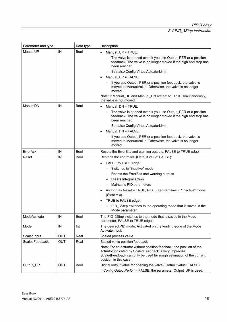
PID is easy 8.4 PID_3Step instruction
Easy Book Manual, 03/2014, A5E02486774-AF 181
Parameter and type Data type Description ManualUP IN Bool • Manual_UP = TRUE:
– The valve is opened even if you use Output_PER or a position feedback. The valve is no longer moved if the high end stop has been reached.
– See also Config.VirtualActuatorLimit • Manual_UP = FALSE:
– If you use Output_PER or a position feedback, the valve is moved to ManualValue. Otherwise, the valve is no longer moved.
Note: If Manual_UP and Manual_DN are set to TRUE simultaneously, the valve is not moved.
ManualDN IN Bool • Manual_DN = TRUE: – The valve is opened even if you use Output_PER or a position
feedback. The valve is no longer moved if the high end stop has been reached.
– See also Config.VirtualActuatorLimit • Manual_DN = FALSE:
– If you use Output_PER or a position feedback, the valve is moved to ManualValue. Otherwise, the valve is no longer moved.
ErrorAck IN Bool Resets the ErrorBits and warning outputs. FALSE to TRUE edge Reset IN Bool Restarts the controller. (Default value: FALSE):
• FALSE to TRUE edge: – Switches to "inactive" mode – Resets the ErrorBits and warning outputs – Clears Integral action – Maintains PID parameters
• As long as Reset = TRUE, PID_3Step remains in "Inactive" mode (State = 0).
• TRUE to FALSE edge: – PID_3Step switches to the operating mode that is saved in the
Mode parameter.
ModeActivate IN Bool The PID_3Step switches to the mode that is saved in the Mode parameter. FALSE to TRUE edge:
Mode IN Int The desired PID mode; Activated on the leading edge of the Mode Activate input.
ScaledInput OUT Real Scaled process value ScaledFeedback OUT Real Scaled valve position feedback
Note: For an actuator without position feedback, the position of the actuator indicated by ScaledFeedback is very imprecise. ScaledFeedback can only be used for rough estimation of the current position in this case.
Output_UP OUT Bool Digital output value for opening the valve. (Default value: FALSE) If Config.OutputPerOn = FALSE, the parameter Output_UP is used.
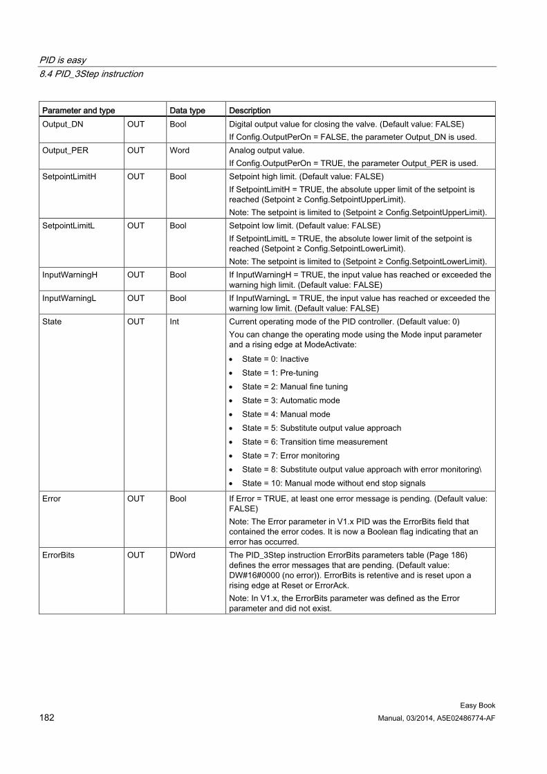
PID is easy 8.4 PID_3Step instruction
Easy Book 182 Manual, 03/2014, A5E02486774-AF
Parameter and type Data type Description Output_DN OUT Bool Digital output value for closing the valve. (Default value: FALSE)
If Config.OutputPerOn = FALSE, the parameter Output_DN is used. Output_PER OUT Word Analog output value.
If Config.OutputPerOn = TRUE, the parameter Output_PER is used. SetpointLimitH OUT Bool Setpoint high limit. (Default value: FALSE)
If SetpointLimitH = TRUE, the absolute upper limit of the setpoint is reached (Setpoint ≥ Config.SetpointUpperLimit). Note: The setpoint is limited to (Setpoint ≥ Config.SetpointUpperLimit).
SetpointLimitL OUT Bool Setpoint low limit. (Default value: FALSE) If SetpointLimitL = TRUE, the absolute lower limit of the setpoint is reached (Setpoint ≥ Config.SetpointLowerLimit). Note: The setpoint is limited to (Setpoint ≥ Config.SetpointLowerLimit).
InputWarningH OUT Bool If InputWarningH = TRUE, the input value has reached or exceeded the warning high limit. (Default value: FALSE)
InputWarningL OUT Bool If InputWarningL = TRUE, the input value has reached or exceeded the warning low limit. (Default value: FALSE)
State OUT Int Current operating mode of the PID controller. (Default value: 0) You can change the operating mode using the Mode input parameter and a rising edge at ModeActivate: • State = 0: Inactive • State = 1: Pre-tuning • State = 2: Manual fine tuning • State = 3: Automatic mode • State = 4: Manual mode • State = 5: Substitute output value approach • State = 6: Transition time measurement • State = 7: Error monitoring • State = 8: Substitute output value approach with error monitoring\ • State = 10: Manual mode without end stop signals
Error OUT Bool If Error = TRUE, at least one error message is pending. (Default value: FALSE) Note: The Error parameter in V1.x PID was the ErrorBits field that contained the error codes. It is now a Boolean flag indicating that an error has occurred.
ErrorBits OUT DWord The PID_3Step instruction ErrorBits parameters table (Page 186) defines the error messages that are pending. (Default value: DW#16#0000 (no error)). ErrorBits is retentive and is reset upon a rising edge at Reset or ErrorAck. Note: In V1.x, the ErrorBits parameter was defined as the Error parameter and did not exist.
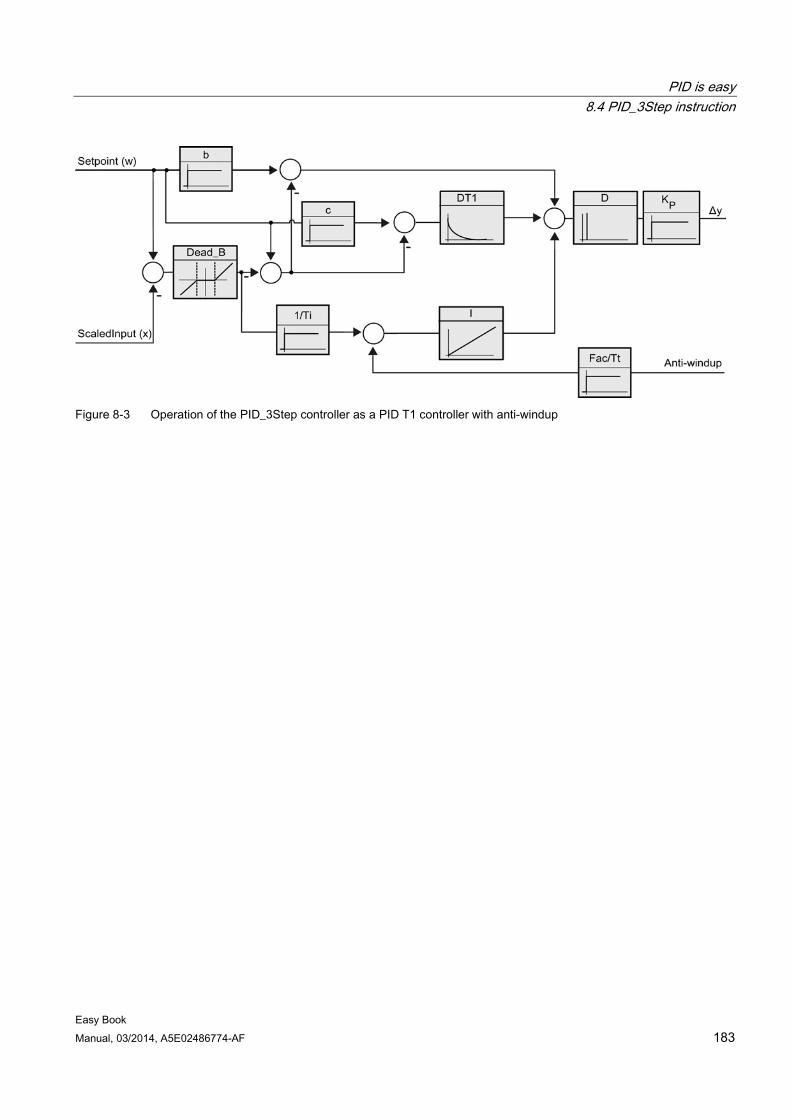
PID is easy 8.4 PID_3Step instruction
Easy Book Manual, 03/2014, A5E02486774-AF 183
Figure 8-3 Operation of the PID_3Step controller as a PID T1 controller with anti-windup
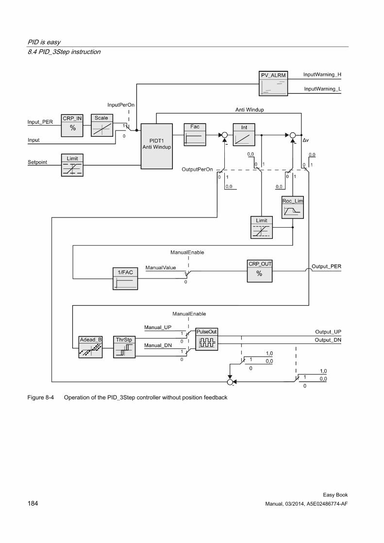
PID is easy 8.4 PID_3Step instruction
Easy Book 184 Manual, 03/2014, A5E02486774-AF
Figure 8-4 Operation of the PID_3Step controller without position feedback
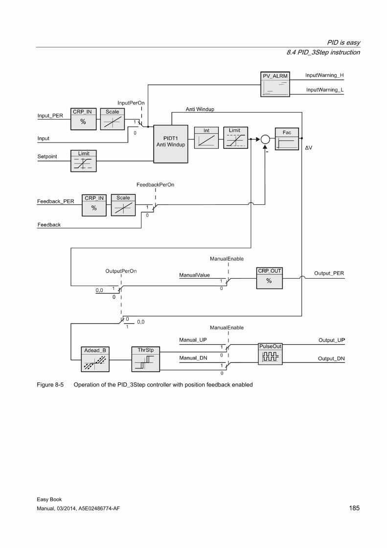
PID is easy 8.4 PID_3Step instruction
Easy Book Manual, 03/2014, A5E02486774-AF 185
Figure 8-5 Operation of the PID_3Step controller with position feedback enabled
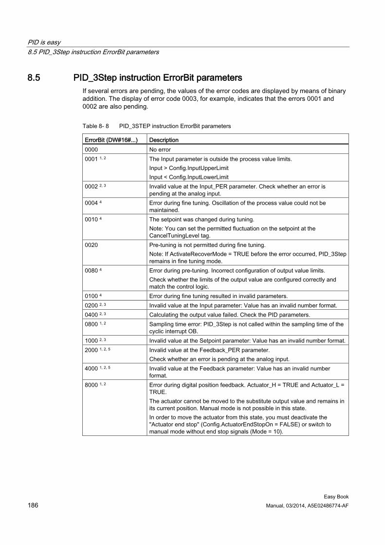
PID is easy 8.5 PID_3Step instruction ErrorBit parameters
Easy Book 186 Manual, 03/2014, A5E02486774-AF
8.5 PID_3Step instruction ErrorBit parameters If several errors are pending, the values of the error codes are displayed by means of binary addition. The display of error code 0003, for example, indicates that the errors 0001 and 0002 are also pending.
Table 8- 8 PID_3STEP instruction ErrorBit parameters
ErrorBit (DW#16#...) Description 0000 No error 0001 1, 2 The Input parameter is outside the process value limits.
Input > Config.InputUpperLimit Input < Config.InputLowerLimit
0002 2, 3 Invalid value at the Input_PER parameter. Check whether an error is pending at the analog input.
0004 4 Error during fine tuning. Oscillation of the process value could not be maintained.
0010 4 The setpoint was changed during tuning. Note: You can set the permitted fluctuation on the setpoint at the CancelTuningLevel tag.
0020 Pre-tuning is not permitted during fine tuning. Note: If ActivateRecoverMode = TRUE before the error occurred, PID_3Step remains in fine tuning mode.
0080 4 Error during pre-tuning. Incorrect configuration of output value limits. Check whether the limits of the output value are configured correctly and match the control logic.
0100 4 Error during fine tuning resulted in invalid parameters. 0200 2, 3 Invalid value at the Input parameter: Value has an invalid number format. 0400 2, 3 Calculating the output value failed. Check the PID parameters. 0800 1, 2 Sampling time error: PID_3Step is not called within the sampling time of the
cyclic interrupt OB. 1000 2, 3 Invalid value at the Setpoint parameter: Value has an invalid number format. 2000 1, 2, 5 Invalid value at the Feedback_PER parameter.
Check whether an error is pending at the analog input. 4000 1, 2, 5 Invalid value at the Feedback parameter: Value has an invalid number
format. 8000 1, 2 Error during digital position feedback. Actuator_H = TRUE and Actuator_L =
TRUE. The actuator cannot be moved to the substitute output value and remains in its current position. Manual mode is not possible in this state. In order to move the actuator from this state, you must deactivate the "Actuator end stop" (Config.ActuatorEndStopOn = FALSE) or switch to manual mode without end stop signals (Mode = 10).
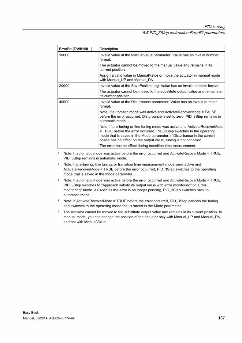
PID is easy 8.5 PID_3Step instruction ErrorBit parameters
Easy Book Manual, 03/2014, A5E02486774-AF 187
ErrorBit (DW#16#...) Description 10000 Invalid value at the ManualValue parameter: Value has an invalid number
format. The actuator cannot be moved to the manual value and remains in its current position. Assign a valid value in ManualValue or move the actuator in manual mode with Manual_UP and Manual_DN.
20000 Invalid value at the SavePosition tag: Value has an invalid number format. The actuator cannot be moved to the substitute output value and remains in its current position.
40000 Invalid value at the Disturbance parameter: Value has an invalid number format. Note: If automatic mode was active and ActivateRecoverMode = FALSE before the error occurred, Disturbance is set to zero. PID_3Step remains in automatic mode. Note: If pre-tuning or fine tuning mode was active and ActivateRecoverMode = TRUE before the error occurred, PID_3Step switches to the operating mode that is saved in the Mode parameter. If Disturbance in the current phase has no effect on the output value, tuning is not canceled. The error has no effect during transition time measurement.
1 Note: If automatic mode was active before the error occurred and ActivateRecoverMode = TRUE, PID_3Step remains in automatic mode.
2 Note: If pre-tuning, fine tuning, or transition time measurement mode were active and ActivateRecoverMode = TRUE before the error occurred, PID_3Step switches to the operating mode that is saved in the Mode parameter.
3 Note: If automatic mode was active before the error occurred and ActivateRecoverMode = TRUE, PID_3Step switches to "Approach substitute output value with error monitoring" or "Error monitoring" mode. As soon as the error is no longer pending, PID_3Step switches back to automatic mode.
4 Note: If ActivateRecoverMode = TRUE before the error occurred, PID_3Step cancels the tuning and switches to the operating mode that is saved in the Mode parameter.
5 The actuator cannot be moved to the substitute output value and remains in its current position. In manual mode, you can change the position of the actuator only with Manual_UP and Manual_DN, and not with ManualValue.
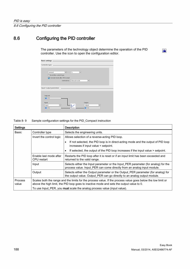
PID is easy 8.6 Configuring the PID controller
Easy Book 188 Manual, 03/2014, A5E02486774-AF
8.6 Configuring the PID controller The parameters of the technology object determine the operation of the PID controller. Use the icon to open the configuration editor.
Table 8- 9 Sample configuration settings for the PID_Compact instruction
Settings Description Basic Controller type Selects the engineering units.
Invert the control logic Allows selection of a reverse-acting PID loop. • If not selected, the PID loop is in direct-acting mode and the output of PID loop
increases if input value < setpoint. • If selected, the output of the PID loop increases if the input value > setpoint.
Enable last mode after CPU restart
Restarts the PID loop after it is reset or if an input limit has been exceeded and returned to the valid range.
Input Selects either the Input parameter or the Input_PER parameter (for analog) for the process value. Input_PER can come directly from an analog input module.
Output Selects either the Output parameter or the Output_PER parameter (for analog) for the output value. Output_PER can go directly to an analog output module.
Process value
Scales both the range and the limits for the process value. If the process value goes below the low limit or above the high limit, the PID loop goes to inactive mode and sets the output value to 0. To use Input_PER, you must scale the analog process value (input value).
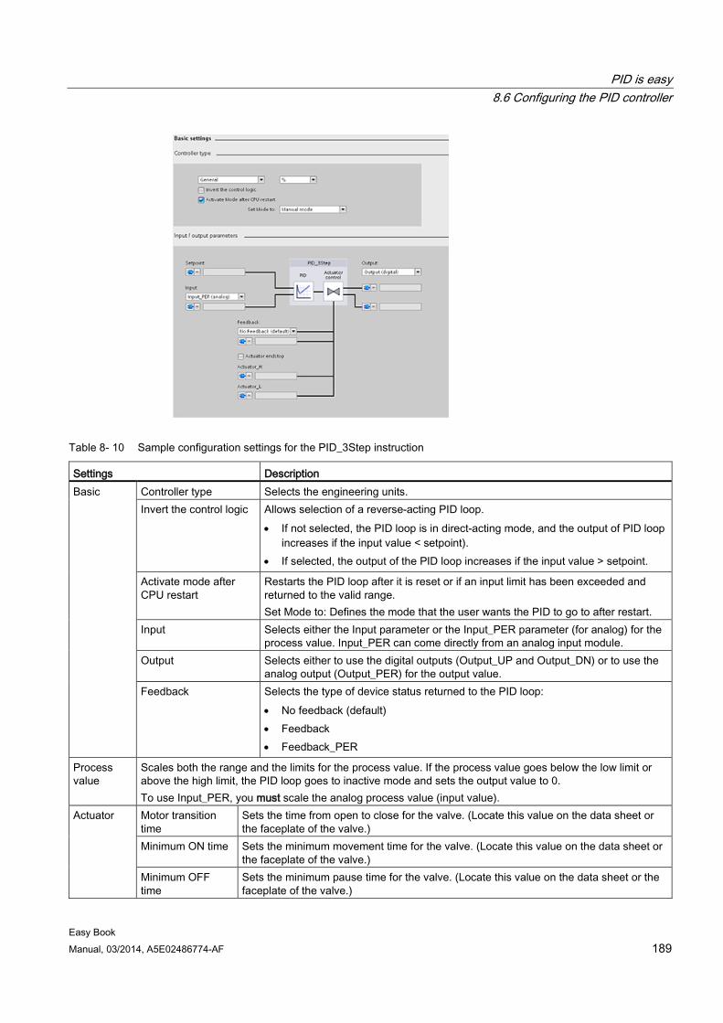
PID is easy 8.6 Configuring the PID controller
Easy Book Manual, 03/2014, A5E02486774-AF 189
Table 8- 10 Sample configuration settings for the PID_3Step instruction
Settings Description Basic Controller type Selects the engineering units.
Invert the control logic Allows selection of a reverse-acting PID loop. • If not selected, the PID loop is in direct-acting mode, and the output of PID loop
increases if the input value < setpoint). • If selected, the output of the PID loop increases if the input value > setpoint.
Activate mode after CPU restart
Restarts the PID loop after it is reset or if an input limit has been exceeded and returned to the valid range. Set Mode to: Defines the mode that the user wants the PID to go to after restart.
Input Selects either the Input parameter or the Input_PER parameter (for analog) for the process value. Input_PER can come directly from an analog input module.
Output Selects either to use the digital outputs (Output_UP and Output_DN) or to use the analog output (Output_PER) for the output value.
Feedback Selects the type of device status returned to the PID loop: • No feedback (default) • Feedback • Feedback_PER
Process value
Scales both the range and the limits for the process value. If the process value goes below the low limit or above the high limit, the PID loop goes to inactive mode and sets the output value to 0. To use Input_PER, you must scale the analog process value (input value).
Actuator Motor transition time
Sets the time from open to close for the valve. (Locate this value on the data sheet or the faceplate of the valve.)
Minimum ON time Sets the minimum movement time for the valve. (Locate this value on the data sheet or the faceplate of the valve.)
Minimum OFF time
Sets the minimum pause time for the valve. (Locate this value on the data sheet or the faceplate of the valve.)
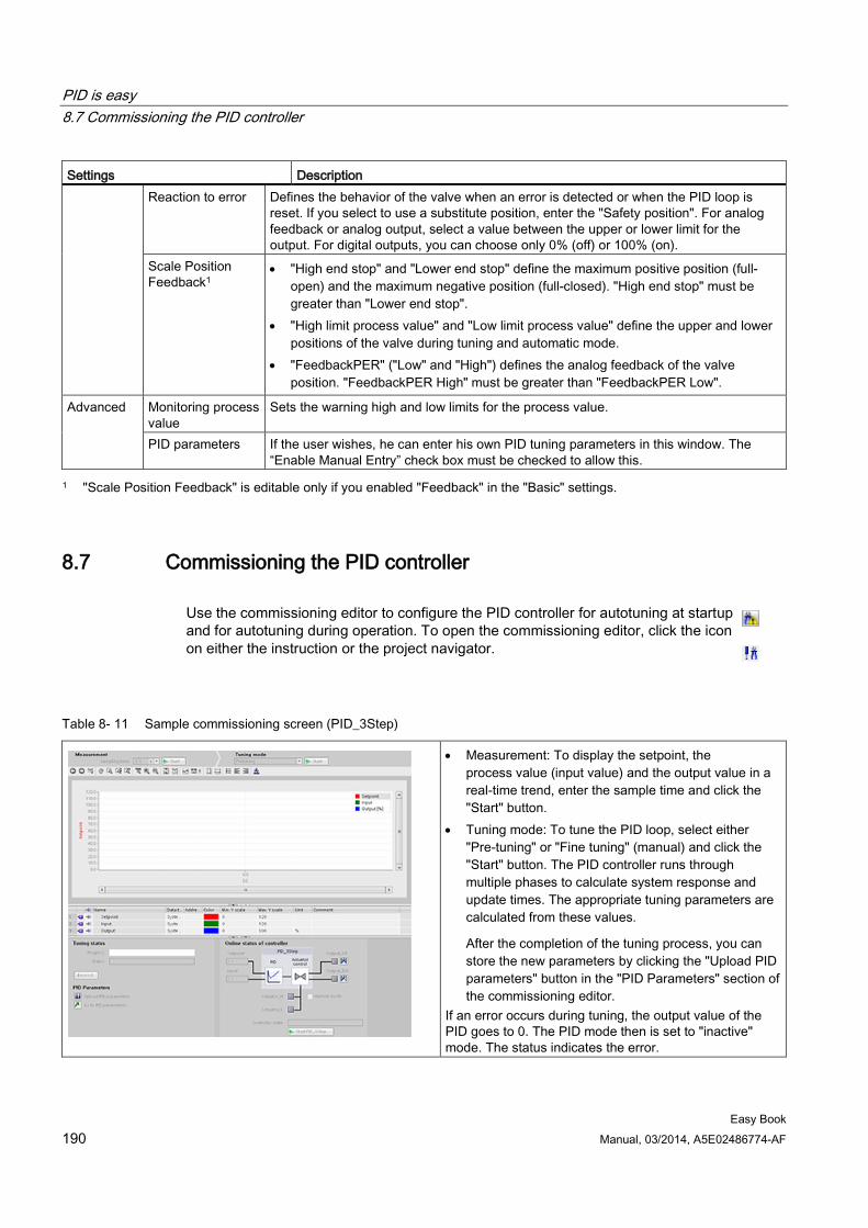
PID is easy 8.7 Commissioning the PID controller
Easy Book 190 Manual, 03/2014, A5E02486774-AF
Settings Description Reaction to error Defines the behavior of the valve when an error is detected or when the PID loop is
reset. If you select to use a substitute position, enter the "Safety position". For analog feedback or analog output, select a value between the upper or lower limit for the output. For digital outputs, you can choose only 0% (off) or 100% (on).
Scale Position Feedback1
• "High end stop" and "Lower end stop" define the maximum positive position (full-open) and the maximum negative position (full-closed). "High end stop" must be greater than "Lower end stop".
• "High limit process value" and "Low limit process value" define the upper and lower positions of the valve during tuning and automatic mode.
• "FeedbackPER" ("Low" and "High") defines the analog feedback of the valve position. "FeedbackPER High" must be greater than "FeedbackPER Low".
Advanced Monitoring process value
Sets the warning high and low limits for the process value.
PID parameters If the user wishes, he can enter his own PID tuning parameters in this window. The “Enable Manual Entry” check box must be checked to allow this.
1 "Scale Position Feedback" is editable only if you enabled "Feedback" in the "Basic" settings.
8.7 Commissioning the PID controller Use the commissioning editor to configure the PID controller for autotuning at startup and for autotuning during operation. To open the commissioning editor, click the icon on either the instruction or the project navigator.
Table 8- 11 Sample commissioning screen (PID_3Step)
• Measurement: To display the setpoint, the process value (input value) and the output value in a real-time trend, enter the sample time and click the "Start" button.
• Tuning mode: To tune the PID loop, select either "Pre-tuning" or "Fine tuning" (manual) and click the "Start" button. The PID controller runs through multiple phases to calculate system response and update times. The appropriate tuning parameters are calculated from these values.
After the completion of the tuning process, you can store the new parameters by clicking the "Upload PID parameters" button in the "PID Parameters" section of the commissioning editor.
If an error occurs during tuning, the output value of the PID goes to 0. The PID mode then is set to "inactive" mode. The status indicates the error.
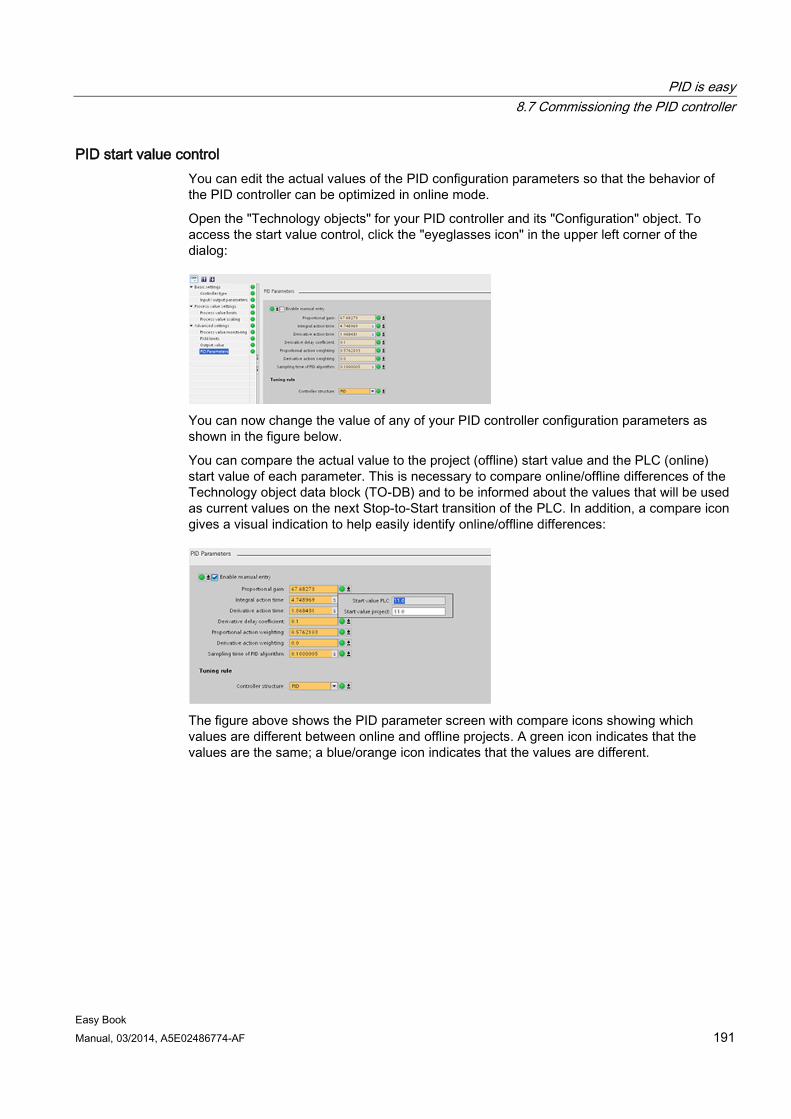
PID is easy 8.7 Commissioning the PID controller
Easy Book Manual, 03/2014, A5E02486774-AF 191
PID start value control You can edit the actual values of the PID configuration parameters so that the behavior of the PID controller can be optimized in online mode.
Open the "Technology objects" for your PID controller and its "Configuration" object. To access the start value control, click the "eyeglasses icon" in the upper left corner of the dialog:
You can now change the value of any of your PID controller configuration parameters as shown in the figure below.
You can compare the actual value to the project (offline) start value and the PLC (online) start value of each parameter. This is necessary to compare online/offline differences of the Technology object data block (TO-DB) and to be informed about the values that will be used as current values on the next Stop-to-Start transition of the PLC. In addition, a compare icon gives a visual indication to help easily identify online/offline differences:
The figure above shows the PID parameter screen with compare icons showing which values are different between online and offline projects. A green icon indicates that the values are the same; a blue/orange icon indicates that the values are different.
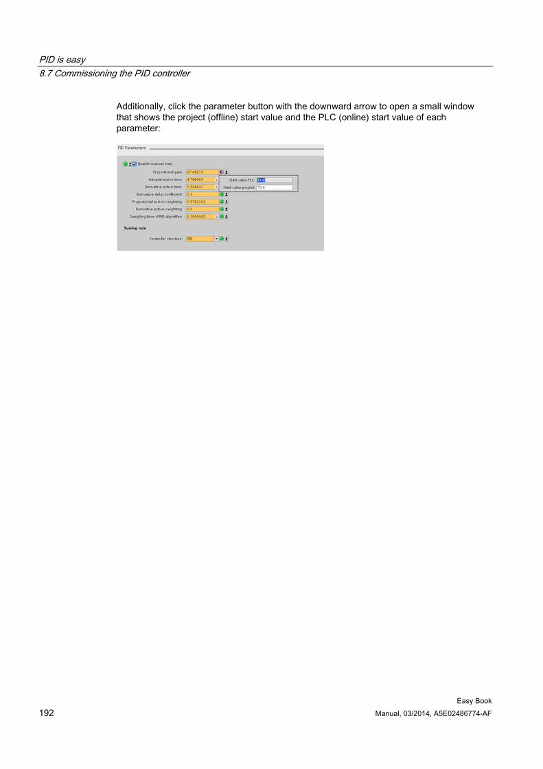
PID is easy 8.7 Commissioning the PID controller
Easy Book 192 Manual, 03/2014, A5E02486774-AF
Additionally, click the parameter button with the downward arrow to open a small window that shows the project (offline) start value and the PLC (online) start value of each parameter:
Easy Book Manual, 03/2014, A5E02486774-AF 193
Web server for easy Internet connectivity 9
The Web server provides Web page access to data about your CPU and to the process data within the CPU. With these Web pages, you access the CPU with the Web browser of your PC or mobile device. The standard web pages allow authorized users to perform a variety of functions:
● You can change the operating mode (STOP and RUN) of the CPU.
● You can monitor and modify the status of the PLC tags.
● You can view and download any data logs being collected by the CPU.
● You can view the diagnostic buffer of the CPU.
● You can update the firmware of the CPU.
The Web server also allows you to create user-defined Web pages that can access CPU data. You can develop these pages with the HTML authoring software of your choice. You insert pre-defined "AWP" (Automation Web Programming) commands in your HTML code to access the data in the CPU.
You set up users and privilege levels for the Web server in the device configuration for the CPU in STEP 7.
Web browser requirement The Web server supports the following PC Web browsers:
● Internet Explorer 8.0 or greater
● Mozilla Firefox 3.0 or greater
● Opera 11.0 or greater
● Google Chrome 21.0 or greater
● Apple Safari 6.0 or greater
The Web server supports the following mobile device Web browsers:
● Internet Explorer 8.0 or greater, for HMI panels
● Mobile Safari, iOS 5.0 or greater
● Mobile Android Browser, 2.3.4 or greater
● Mobile Google Chrome, Android 4.0 or greater
For browser-related restrictions that can interfere with the display of standard or user-defined Web pages, see the topics about constraints (Page 196).
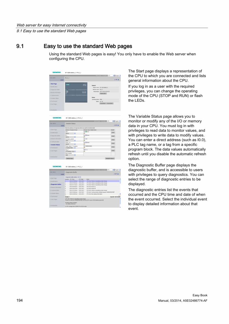
Web server for easy Internet connectivity 9.1 Easy to use the standard Web pages
Easy Book 194 Manual, 03/2014, A5E02486774-AF
9.1 Easy to use the standard Web pages Using the standard Web pages is easy! You only have to enable the Web server when configuring the CPU.
The Start page displays a representation of the CPU to which you are connected and lists general information about the CPU. If you log in as a user with the required privileges, you can change the operating mode of the CPU (STOP and RUN) or flash the LEDs.
The Variable Status page allows you to monitor or modify any of the I/O or memory data in your CPU. You must log in with privileges to read data to monitor values, and with privileges to write data to modify values. You can enter a direct address (such as I0.0), a PLC tag name, or a tag from a specific program block. The data values automatically refresh until you disable the automatic refresh option.
The Diagnostic Buffer page displays the diagnostic buffer, and is accessible to users with privileges to query diagnostics. You can select the range of diagnostic entries to be displayed. The diagnostic entries list the events that occurred and the CPU time and date of when the event occurred. Select the individual event to display detailed information about that event.
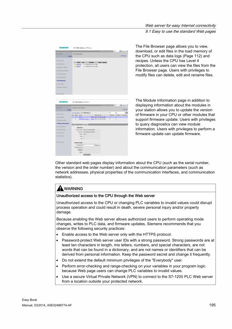
Web server for easy Internet connectivity 9.1 Easy to use the standard Web pages
Easy Book Manual, 03/2014, A5E02486774-AF 195
The File Browser page allows you to view, download, or edit files in the load memory of the CPU such as data logs (Page 112) and recipes. Unless the CPU has Level 4 protection, all users can view the files from the File Browser page. Users with privileges to modify files can delete, edit and rename files.
The Module Information page in addition to displaying information about the modules in your station allows you to update the version of firmware in your CPU or other modules that support firmware update. Users with privileges to query diagnostics can view module information. Users with privileges to perform a firmware update can update firmware.
Other standard web pages display information about the CPU (such as the serial number, the version and the order number) and about the communication parameters (such as network addresses, physical properties of the communication interfaces, and communication statistics).
WARNING
Unauthorized access to the CPU through the Web server
Unauthorized access to the CPU or changing PLC variables to invalid values could disrupt process operation and could result in death, severe personal injury and/or property damage.
Because enabling the Web server allows authorized users to perform operating mode changes, writes to PLC data, and firmware updates, Siemens recommends that you observe the following security practices: • Enable access to the Web server only with the HTTPS protocol. • Password-protect Web server user IDs with a strong password. Strong passwords are at
least ten characters in length, mix letters, numbers, and special characters, are not words that can be found in a dictionary, and are not names or identifiers that can be derived from personal information. Keep the password secret and change it frequently.
• Do not extend the default minimum privileges of the "Everybody" user. • Perform error-checking and range-checking on your variables in your program logic
because Web page users can change PLC variables to invalid values. • Use a secure Virtual Private Network (VPN) to connect to the S7-1200 PLC Web server
from a location outside your protected network.
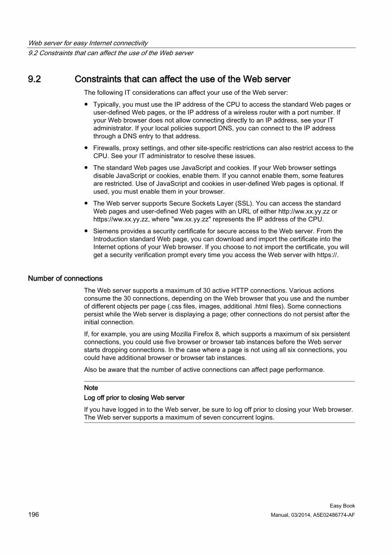
Web server for easy Internet connectivity 9.2 Constraints that can affect the use of the Web server
Easy Book 196 Manual, 03/2014, A5E02486774-AF
9.2 Constraints that can affect the use of the Web server The following IT considerations can affect your use of the Web server:
● Typically, you must use the IP address of the CPU to access the standard Web pages or user-defined Web pages, or the IP address of a wireless router with a port number. If your Web browser does not allow connecting directly to an IP address, see your IT administrator. If your local policies support DNS, you can connect to the IP address through a DNS entry to that address.
● Firewalls, proxy settings, and other site-specific restrictions can also restrict access to the CPU. See your IT administrator to resolve these issues.
● The standard Web pages use JavaScript and cookies. If your Web browser settings disable JavaScript or cookies, enable them. If you cannot enable them, some features are restricted. Use of JavaScript and cookies in user-defined Web pages is optional. If used, you must enable them in your browser.
● The Web server supports Secure Sockets Layer (SSL). You can access the standard Web pages and user-defined Web pages with an URL of either http://ww.xx.yy.zz or https://ww.xx.yy.zz, where "ww.xx.yy.zz" represents the IP address of the CPU.
● Siemens provides a security certificate for secure access to the Web server. From the Introduction standard Web page, you can download and import the certificate into the Internet options of your Web browser. If you choose to not import the certificate, you will get a security verification prompt every time you access the Web server with https://.
Number of connections The Web server supports a maximum of 30 active HTTP connections. Various actions consume the 30 connections, depending on the Web browser that you use and the number of different objects per page (.css files, images, additional .html files). Some connections persist while the Web server is displaying a page; other connections do not persist after the initial connection.
If, for example, you are using Mozilla Firefox 8, which supports a maximum of six persistent connections, you could use five browser or browser tab instances before the Web server starts dropping connections. In the case where a page is not using all six connections, you could have additional browser or browser tab instances.
Also be aware that the number of active connections can affect page performance.
Note Log off prior to closing Web server
If you have logged in to the Web server, be sure to log off prior to closing your Web browser. The Web server supports a maximum of seven concurrent logins.
Web server for easy Internet connectivity 9.2 Constraints that can affect the use of the Web server
Easy Book Manual, 03/2014, A5E02486774-AF 197
9.2.1 Feature restrictions when the Internet options disable JavaScript The standard Web pages use HTML, JavaScript, and cookies. If your site restricts the use of JavaScript and cookies, then enable them for the pages to function properly. If you cannot enable JavaScript for your Web browser, the features that use JavaScript controls cannot run.
General The pages do not update dynamically. You must manually refresh the page with the Refresh icon to view fresh data.
Diagnostic Buffer page The Diagnostic Buffer page uses JavaScript as follows:
● Displaying the event details: With JavaScript, you select a row in the diagnostic buffer to see the details in the bottom section. Without JavaScript, you must click the event field hyperlink of a diagnostic buffer entry to see the event data in the bottom section.
● Changing the range of diagnostic buffer entries to view: With JavaScript, you use the drop-down list at the top to select the range of diagnostic buffer entries to view, and the page automatically updates. Without JavaScript, you use the drop-down list at the top to select the range of diagnostic buffer entries to view, but you must then click the "Go" link to update the diagnostic buffer page with the range you selected from the drop-down list.
Note that the "Go" and the event field hyperlinks are only visible when JavaScript is not enabled. They are not necessary and therefore are not present when JavaScript is enabled.
Module Information page Without JavaScript enabled, the following restrictions apply:
● You cannot filter the data.
● You cannot sort fields.
Variable Status page Without JavaScript enabled, the following restrictions apply:
● After you enter each variable, you must manually set the focus to the "New variable" row to enter a new variable.
● Selecting a display format does not automatically change the data value display to the selected format. You must click the "Monitor value" button to refresh the display with the new format.
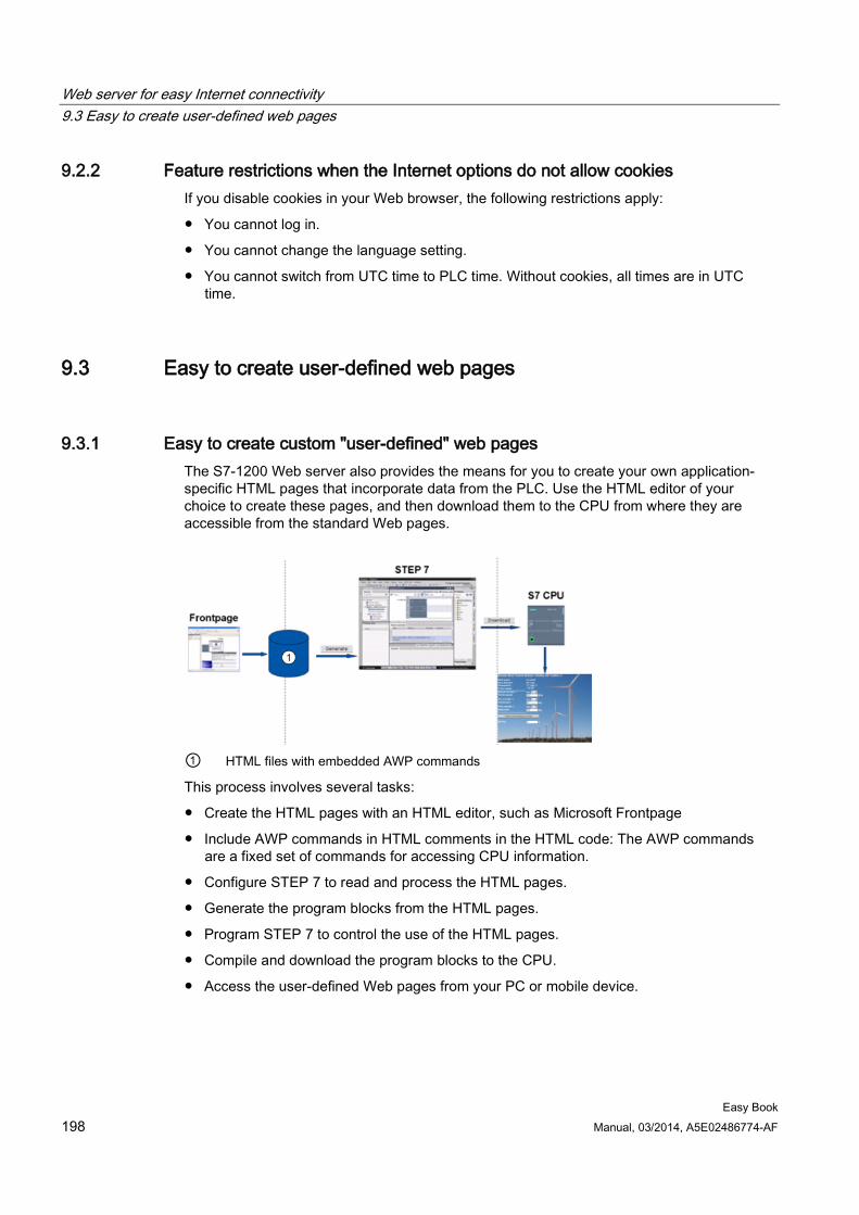
Web server for easy Internet connectivity 9.3 Easy to create user-defined web pages
Easy Book 198 Manual, 03/2014, A5E02486774-AF
9.2.2 Feature restrictions when the Internet options do not allow cookies If you disable cookies in your Web browser, the following restrictions apply:
● You cannot log in.
● You cannot change the language setting.
● You cannot switch from UTC time to PLC time. Without cookies, all times are in UTC time.
9.3 Easy to create user-defined web pages
9.3.1 Easy to create custom "user-defined" web pages The S7-1200 Web server also provides the means for you to create your own application-specific HTML pages that incorporate data from the PLC. Use the HTML editor of your choice to create these pages, and then download them to the CPU from where they are accessible from the standard Web pages.
① HTML files with embedded AWP commands
This process involves several tasks:
● Create the HTML pages with an HTML editor, such as Microsoft Frontpage
● Include AWP commands in HTML comments in the HTML code: The AWP commands are a fixed set of commands for accessing CPU information.
● Configure STEP 7 to read and process the HTML pages.
● Generate the program blocks from the HTML pages.
● Program STEP 7 to control the use of the HTML pages.
● Compile and download the program blocks to the CPU.
● Access the user-defined Web pages from your PC or mobile device.
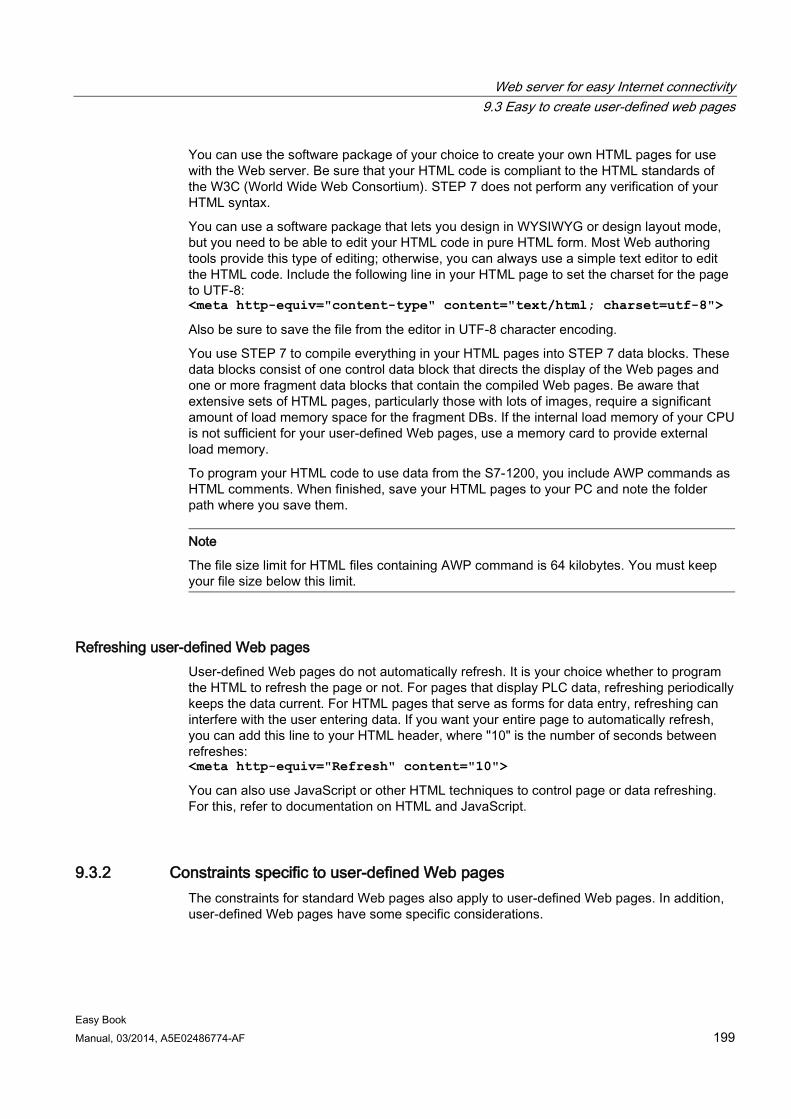
Web server for easy Internet connectivity 9.3 Easy to create user-defined web pages
Easy Book Manual, 03/2014, A5E02486774-AF 199
You can use the software package of your choice to create your own HTML pages for use with the Web server. Be sure that your HTML code is compliant to the HTML standards of the W3C (World Wide Web Consortium). STEP 7 does not perform any verification of your HTML syntax.
You can use a software package that lets you design in WYSIWYG or design layout mode, but you need to be able to edit your HTML code in pure HTML form. Most Web authoring tools provide this type of editing; otherwise, you can always use a simple text editor to edit the HTML code. Include the following line in your HTML page to set the charset for the page to UTF-8: <meta http-equiv="content-type" content="text/html; charset=utf-8">
Also be sure to save the file from the editor in UTF-8 character encoding.
You use STEP 7 to compile everything in your HTML pages into STEP 7 data blocks. These data blocks consist of one control data block that directs the display of the Web pages and one or more fragment data blocks that contain the compiled Web pages. Be aware that extensive sets of HTML pages, particularly those with lots of images, require a significant amount of load memory space for the fragment DBs. If the internal load memory of your CPU is not sufficient for your user-defined Web pages, use a memory card to provide external load memory.
To program your HTML code to use data from the S7-1200, you include AWP commands as HTML comments. When finished, save your HTML pages to your PC and note the folder path where you save them.
Note
The file size limit for HTML files containing AWP command is 64 kilobytes. You must keep your file size below this limit.
Refreshing user-defined Web pages User-defined Web pages do not automatically refresh. It is your choice whether to program the HTML to refresh the page or not. For pages that display PLC data, refreshing periodically keeps the data current. For HTML pages that serve as forms for data entry, refreshing can interfere with the user entering data. If you want your entire page to automatically refresh, you can add this line to your HTML header, where "10" is the number of seconds between refreshes: <meta http-equiv="Refresh" content="10">
You can also use JavaScript or other HTML techniques to control page or data refreshing. For this, refer to documentation on HTML and JavaScript.
9.3.2 Constraints specific to user-defined Web pages The constraints for standard Web pages also apply to user-defined Web pages. In addition, user-defined Web pages have some specific considerations.
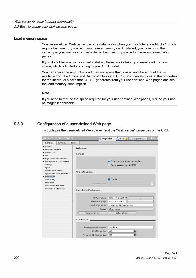
Web server for easy Internet connectivity 9.3 Easy to create user-defined web pages
Easy Book 200 Manual, 03/2014, A5E02486774-AF
Load memory space Your user-defined Web pages become data blocks when you click "Generate blocks", which require load memory space. If you have a memory card installed, you have up to the capacity of your memory card as external load memory space for the user-defined Web pages.
If you do not have a memory card installed, these blocks take up internal load memory space, which is limited according to your CPU model.
You can check the amount of load memory space that is used and the amount that is available from the Online and Diagnostic tools in STEP 7. You can also look at the properties for the individual blocks that STEP 7 generates from your user-defined Web pages and see the load memory consumption.
Note
If you need to reduce the space required for your user-defined Web pages, reduce your use of images if applicable.
9.3.3 Configuration of a user-defined Web page To configure the user-defined Web pages, edit the "Web server" properties of the CPU.
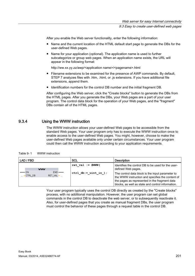
Web server for easy Internet connectivity 9.3 Easy to create user-defined web pages
Easy Book Manual, 03/2014, A5E02486774-AF 201
After you enable the Web server functionality, enter the following information:
● Name and the current location of the HTML default start page to generate the DBs for the user-defined Web pages.
● Name for your application (optional). The application name is used to further subcategorize or group web pages. When an application name exists, the URL will appear in the following format:
http://ww.xx.yy.zz/awp/<application name>/<pagename>.html
● Filename extensions to be examined for the presence of AWP commands. By default, STEP 7 analyzes files with .htm, .html, or .js extensions. If you have additional file extensions, append them.
● Identification numbers for the control DB number and the initial fragment DB.
After configuring the Web server, click the "Create blocks" button to generate the DBs from the HTML pages. After you generate the DBs, your Web pages are a part of your user program. The control data block for the operation of your Web pages, and the "fragment" DBs contain all of the HTML pages.
9.3.4 Using the WWW instruction The WWW instruction allows your user-defined Web pages to be accessible from the standard Web pages. Your user program only has to execute the WWW instruction once to enable access to the user-defined Web pages. You might, however, choose to make the user-defined Web pages available only under certain circumstances. Your user program could then call the WWW instruction according to your application requirements.
Table 9- 1 WWW instruction
LAD / FBD SCL Description
ret_val := #WWW( ctrl_db:=_uint_in_);
Identifies the control DB to be used for the user-defined Web pages. The control data block is the input parameter to the WWW instruction and specifies the content of the pages as represented in the fragment data blocks, as well as state and control information.
Your user program typically uses the control DB directly as created by the "Create blocks" process, with no additional manipulation. However, the user program can set global commands in the control DB to deactivate the web server, or to subsequently reactivate it. Also, for user-defined pages that you create as manual fragment DBs, the user program must control the behavior of these pages through a request table in the control DB.

Web server for easy Internet connectivity 9.3 Easy to create user-defined web pages
Easy Book 202 Manual, 03/2014, A5E02486774-AF
Easy Book Manual, 03/2014, A5E02486774-AF 203
Motion control is easy 10
The CPU provides motion control functionality for the operation of stepper motors and servo motors with pulse interface. The motion control functionality takes over the control and monitoring of the drives.
● The "Axis" technology object configures the mechanical drive data, drive interface, dynamic parameters, and other drive properties.
● You configure the pulse and direction outputs of the CPU for controlling the drive.
● Your user program uses the motion control instructions to control the axis and to initiate motion tasks.
● Use the PROFINET interface to establish the online connection between the CPU and the programming device. In addition to the online functions of the CPU, additional commissioning and diagnostic functions are available for motion control.
Note
Changes that you make to the motion control configuration and download in RUN mode do not take effect until the CPU transitions from STOP to RUN mode.
① PROFINET
② Pulse and direction outputs
③ Power section for stepper motor
④ Power section for servo motor
The DC/DC/DC variants of the CPU S7-1200 have onboard outputs for direct control of drives. The relay variants of the CPU require the signal board with DC outputs for drive control.
A signal board (SB) expands the onboard I/O to include a few additional I/O points. An SB with two digital outputs can be used as pulse and direction outputs to control one motor. An SB with four digital outputs can be used as pulse and direction outputs to control two motors. Built-in relay outputs cannot be used as pulse outputs to control motors. Whether you use onboard I/O or SB I/O or a combination of both, you can have a maximum number of four pulse generators.
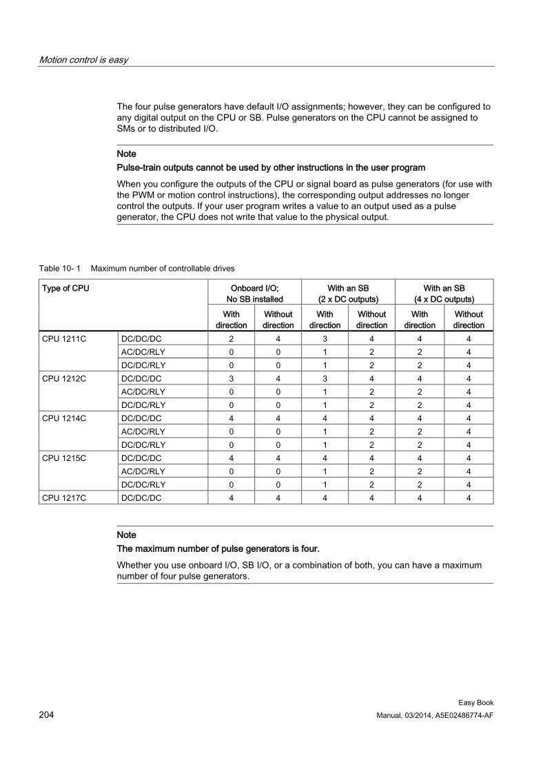
Motion control is easy
Easy Book 204 Manual, 03/2014, A5E02486774-AF
The four pulse generators have default I/O assignments; however, they can be configured to any digital output on the CPU or SB. Pulse generators on the CPU cannot be assigned to SMs or to distributed I/O.
Note Pulse-train outputs cannot be used by other instructions in the user program
When you configure the outputs of the CPU or signal board as pulse generators (for use with the PWM or motion control instructions), the corresponding output addresses no longer control the outputs. If your user program writes a value to an output used as a pulse generator, the CPU does not write that value to the physical output.
Table 10- 1 Maximum number of controllable drives
Type of CPU Onboard I/O; No SB installed
With an SB (2 x DC outputs)
With an SB (4 x DC outputs)
With direction
Without direction
With direction
Without direction
With direction
Without direction
CPU 1211C DC/DC/DC 2 4 3 4 4 4 AC/DC/RLY 0 0 1 2 2 4 DC/DC/RLY 0 0 1 2 2 4
CPU 1212C DC/DC/DC 3 4 3 4 4 4 AC/DC/RLY 0 0 1 2 2 4 DC/DC/RLY 0 0 1 2 2 4
CPU 1214C DC/DC/DC 4 4 4 4 4 4 AC/DC/RLY 0 0 1 2 2 4 DC/DC/RLY 0 0 1 2 2 4
CPU 1215C DC/DC/DC 4 4 4 4 4 4 AC/DC/RLY 0 0 1 2 2 4 DC/DC/RLY 0 0 1 2 2 4
CPU 1217C DC/DC/DC 4 4 4 4 4 4
Note The maximum number of pulse generators is four.
Whether you use onboard I/O, SB I/O, or a combination of both, you can have a maximum number of four pulse generators.
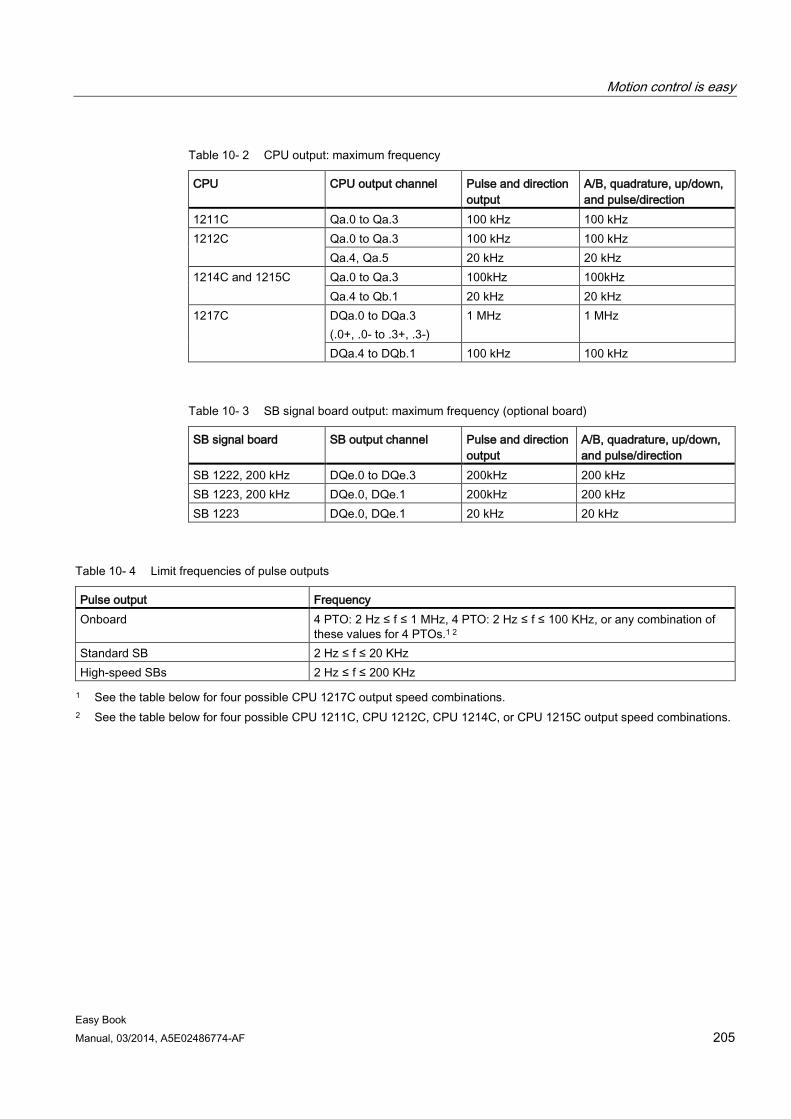
Motion control is easy
Easy Book Manual, 03/2014, A5E02486774-AF 205
Table 10- 2 CPU output: maximum frequency
CPU CPU output channel Pulse and direction output
A/B, quadrature, up/down, and pulse/direction
1211C Qa.0 to Qa.3 100 kHz 100 kHz 1212C Qa.0 to Qa.3 100 kHz 100 kHz
Qa.4, Qa.5 20 kHz 20 kHz 1214C and 1215C Qa.0 to Qa.3 100kHz 100kHz
Qa.4 to Qb.1 20 kHz 20 kHz 1217C DQa.0 to DQa.3
(.0+, .0- to .3+, .3-) 1 MHz 1 MHz
DQa.4 to DQb.1 100 kHz 100 kHz
Table 10- 3 SB signal board output: maximum frequency (optional board)
SB signal board SB output channel Pulse and direction output
A/B, quadrature, up/down, and pulse/direction
SB 1222, 200 kHz DQe.0 to DQe.3 200kHz 200 kHz SB 1223, 200 kHz DQe.0, DQe.1 200kHz 200 kHz SB 1223 DQe.0, DQe.1 20 kHz 20 kHz
Table 10- 4 Limit frequencies of pulse outputs
Pulse output Frequency Onboard 4 PTO: 2 Hz ≤ f ≤ 1 MHz, 4 PTO: 2 Hz ≤ f ≤ 100 KHz, or any combination of
these values for 4 PTOs.1 2 Standard SB 2 Hz ≤ f ≤ 20 KHz High-speed SBs 2 Hz ≤ f ≤ 200 KHz 1 See the table below for four possible CPU 1217C output speed combinations.
2 See the table below for four possible CPU 1211C, CPU 1212C, CPU 1214C, or CPU 1215C output speed combinations.
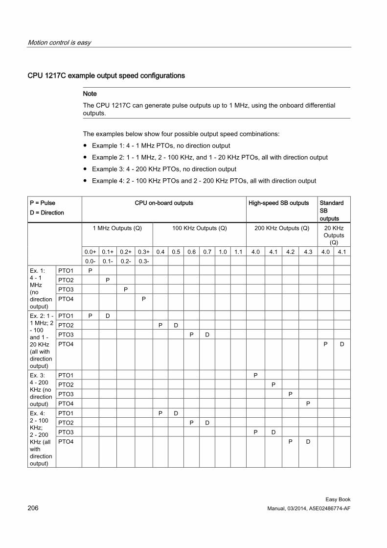
Motion control is easy
Easy Book 206 Manual, 03/2014, A5E02486774-AF
CPU 1217C example output speed configurations
Note
The CPU 1217C can generate pulse outputs up to 1 MHz, using the onboard differential outputs.
The examples below show four possible output speed combinations:
● Example 1: 4 - 1 MHz PTOs, no direction output
● Example 2: 1 - 1 MHz, 2 - 100 KHz, and 1 - 20 KHz PTOs, all with direction output
● Example 3: 4 - 200 KHz PTOs, no direction output
● Example 4: 2 - 100 KHz PTOs and 2 - 200 KHz PTOs, all with direction output
P = Pulse D = Direction
CPU on-board outputs High-speed SB outputs Standard SB outputs
1 MHz Outputs (Q) 100 KHz Outputs (Q) 200 KHz Outputs (Q) 20 KHz Outputs
(Q) 0.0+ 0.1+ 0.2+ 0.3+ 0.4 0.5 0.6 0.7 1.0 1.1 4.0 4.1 4.2 4.3 4.0 4.1 0.0- 0.1- 0.2- 0.3-
Ex. 1: 4 - 1 MHz (no direction output)
PTO1 P PTO2 P PTO3 P PTO4 P
Ex. 2: 1 - 1 MHz; 2 - 100 and 1 - 20 KHz (all with direction output)
PTO1 P D PTO2 P D PTO3 P D PTO4 P D
Ex. 3: 4 - 200 KHz (no direction output)
PTO1 P PTO2 P PTO3 P PTO4 P
Ex. 4: 2 - 100 KHz; 2 - 200 KHz (all with direction output)
PTO1 P D PTO2 P D PTO3 P D PTO4 P D
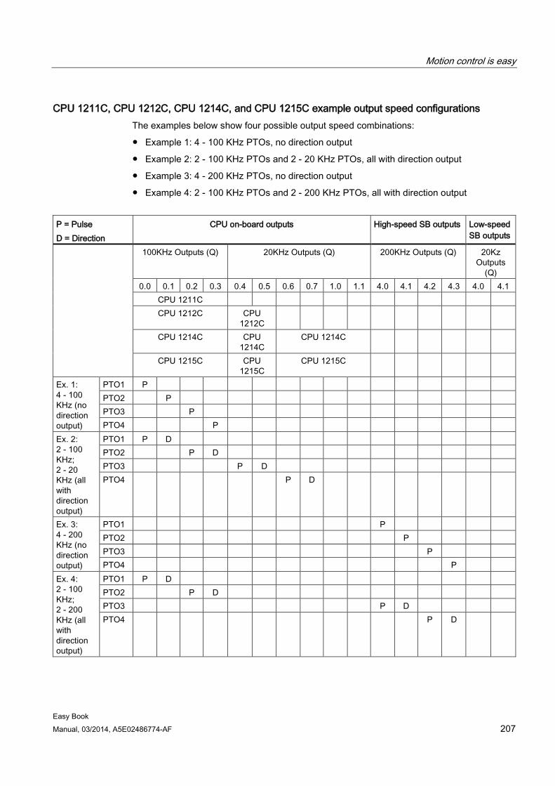
Motion control is easy
Easy Book Manual, 03/2014, A5E02486774-AF 207
CPU 1211C, CPU 1212C, CPU 1214C, and CPU 1215C example output speed configurations The examples below show four possible output speed combinations:
● Example 1: 4 - 100 KHz PTOs, no direction output
● Example 2: 2 - 100 KHz PTOs and 2 - 20 KHz PTOs, all with direction output
● Example 3: 4 - 200 KHz PTOs, no direction output
● Example 4: 2 - 100 KHz PTOs and 2 - 200 KHz PTOs, all with direction output
P = Pulse D = Direction
CPU on-board outputs High-speed SB outputs Low-speed SB outputs
100KHz Outputs (Q) 20KHz Outputs (Q) 200KHz Outputs (Q) 20Kz Outputs
(Q) 0.0 0.1 0.2 0.3 0.4 0.5 0.6 0.7 1.0 1.1 4.0 4.1 4.2 4.3 4.0 4.1
CPU 1211C CPU 1212C CPU
1212C
CPU 1214C CPU 1214C
CPU 1214C
CPU 1215C CPU 1215C
CPU 1215C
Ex. 1: 4 - 100 KHz (no direction output)
PTO1 P PTO2 P PTO3 P PTO4 P
Ex. 2: 2 - 100 KHz; 2 - 20 KHz (all with direction output)
PTO1 P D PTO2 P D PTO3 P D PTO4 P D
Ex. 3: 4 - 200 KHz (no direction output)
PTO1 P PTO2 P PTO3 P PTO4 P
Ex. 4: 2 - 100 KHz; 2 - 200 KHz (all with direction output)
PTO1 P D PTO2 P D PTO3 P D PTO4 P D
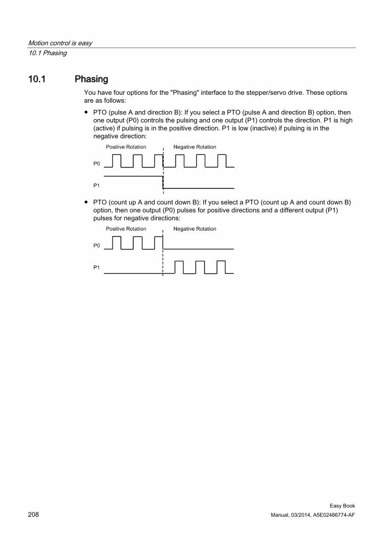
Motion control is easy 10.1 Phasing
Easy Book 208 Manual, 03/2014, A5E02486774-AF
10.1 Phasing You have four options for the "Phasing" interface to the stepper/servo drive. These options are as follows:
● PTO (pulse A and direction B): If you select a PTO (pulse A and direction B) option, then one output (P0) controls the pulsing and one output (P1) controls the direction. P1 is high (active) if pulsing is in the positive direction. P1 is low (inactive) if pulsing is in the negative direction:
● PTO (count up A and count down B): If you select a PTO (count up A and count down B)
option, then one output (P0) pulses for positive directions and a different output (P1) pulses for negative directions:
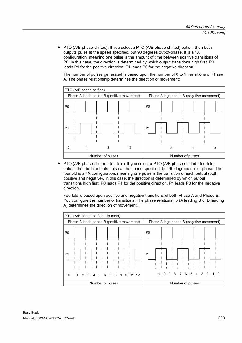
Motion control is easy 10.1 Phasing
Easy Book Manual, 03/2014, A5E02486774-AF 209
● PTO (A/B phase-shifted): If you select a PTO (A/B phase-shifted) option, then both outputs pulse at the speed specified, but 90 degrees out-of-phase. It is a 1X configuration, meaning one pulse is the amount of time between positive transitions of P0. In this case, the direction is determined by which output transitions high first. P0 leads P1 for the positive direction. P1 leads P0 for the negative direction.
The number of pulses generated is based upon the number of 0 to 1 transitions of Phase A. The phase relationship determines the direction of movement:
PTO (A/B phase-shifted) Phase A leads phase B (positive movement) Phase A lags phase B (negative movement)
Number of pulses Number of pulses
● PTO (A/B phase-shifted - fourfold): If you select a PTO (A/B phase-shifted - fourfold) option, then both outputs pulse at the speed specified, but 90 degrees out-of-phase. The fourfold is a 4X configuration, meaning one pulse is the transition of each output (both positive and negative). In this case, the direction is determined by which output transitions high first. P0 leads P1 for the positive direction. P1 leads P0 for the negative direction.
Fourfold is based upon positive and negative transitions of both Phase A and Phase B. You configure the number of transitions. The phase relationship (A leading B or B leading A) determines the direction of movement.
PTO (A/B phase-shifted - fourfold) Phase A leads phase B (positive movement) Phase A lags phase B (negative movement)
Number of pulses Number of pulses
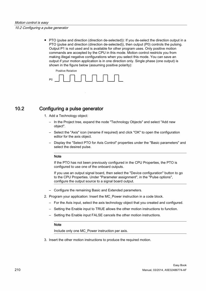
Motion control is easy 10.2 Configuring a pulse generator
Easy Book 210 Manual, 03/2014, A5E02486774-AF
● PTO (pulse and direction (direction de-selected)): If you de-select the direction output in a PTO (pulse and direction (direction de-selected)), then output (P0) controls the pulsing. Output P1 is not used and is available for other program uses. Only positive motion commands are accepted by the CPU in this mode. Motion control restricts you from making illegal negative configurations when you select this mode. You can save an output if your motion application is in one direction only. Single phase (one output) is shown in the figure below (assuming positive polarity):
10.2 Configuring a pulse generator 1. Add a Technology object:
– In the Project tree, expand the node "Technology Objects" and select "Add new object".
– Select the "Axis" icon (rename if required) and click "OK" to open the configuration editor for the axis object.
– Display the "Select PTO for Axis Control" properties under the "Basic parameters" and select the desired pulse.
Note
If the PTO has not been previously configured in the CPU Properties, the PTO is configured to use one of the onboard outputs.
If you use an output signal board, then select the "Device configuration" button to go to the CPU Properties. Under "Parameter assignment", in the "Pulse options", configure the output source to a signal board output.
– Configure the remaining Basic and Extended parameters.
2. Program your application: Insert the MC_Power instruction in a code block.
– For the Axis input, select the axis technology object that you created and configured.
– Setting the Enable input to TRUE allows the other motion instructions to function.
– Setting the Enable input FALSE cancels the other motion instructions.
Note
Include only one MC_Power instruction per axis.
3. Insert the other motion instructions to produce the required motion.
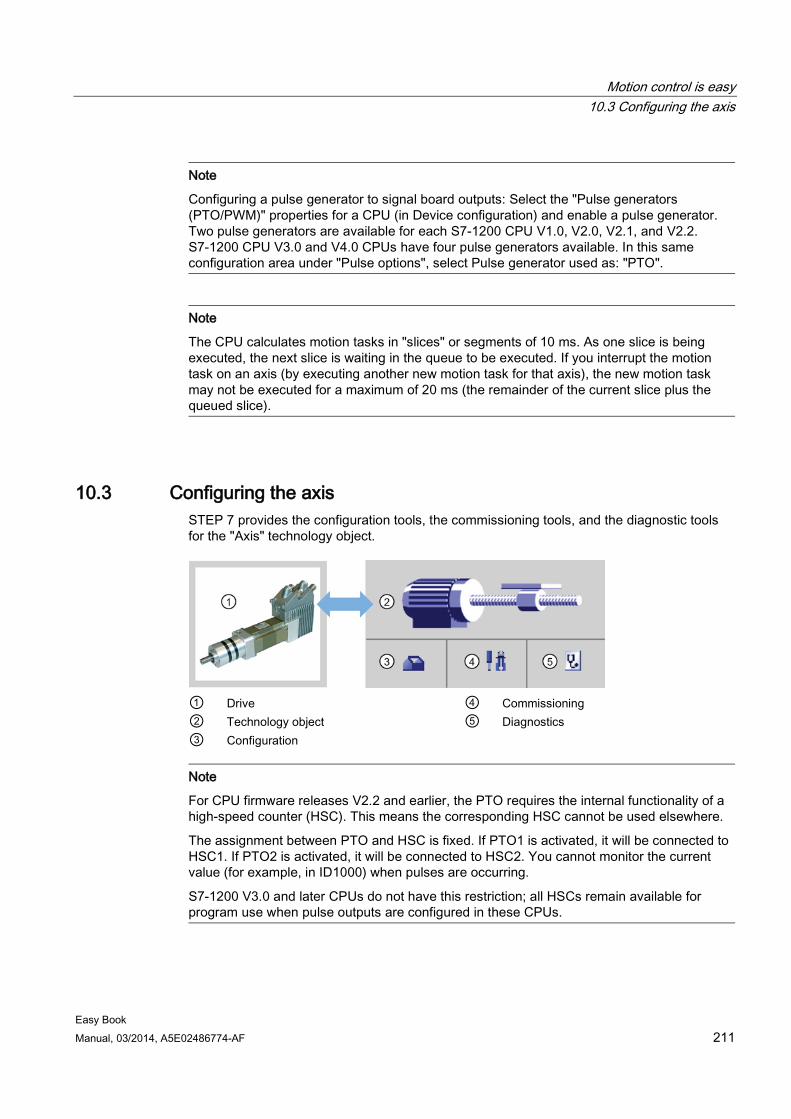
Motion control is easy 10.3 Configuring the axis
Easy Book Manual, 03/2014, A5E02486774-AF 211
Note
Configuring a pulse generator to signal board outputs: Select the "Pulse generators (PTO/PWM)" properties for a CPU (in Device configuration) and enable a pulse generator. Two pulse generators are available for each S7-1200 CPU V1.0, V2.0, V2.1, and V2.2. S7-1200 CPU V3.0 and V4.0 CPUs have four pulse generators available. In this same configuration area under "Pulse options", select Pulse generator used as: "PTO".
Note
The CPU calculates motion tasks in "slices" or segments of 10 ms. As one slice is being executed, the next slice is waiting in the queue to be executed. If you interrupt the motion task on an axis (by executing another new motion task for that axis), the new motion task may not be executed for a maximum of 20 ms (the remainder of the current slice plus the queued slice).
10.3 Configuring the axis STEP 7 provides the configuration tools, the commissioning tools, and the diagnostic tools for the "Axis" technology object.
① Drive ④ Commissioning ② Technology object ⑤ Diagnostics ③ Configuration
Note
For CPU firmware releases V2.2 and earlier, the PTO requires the internal functionality of a high-speed counter (HSC). This means the corresponding HSC cannot be used elsewhere.
The assignment between PTO and HSC is fixed. If PTO1 is activated, it will be connected to HSC1. If PTO2 is activated, it will be connected to HSC2. You cannot monitor the current value (for example, in ID1000) when pulses are occurring.
S7-1200 V3.0 and later CPUs do not have this restriction; all HSCs remain available for program use when pulse outputs are configured in these CPUs.
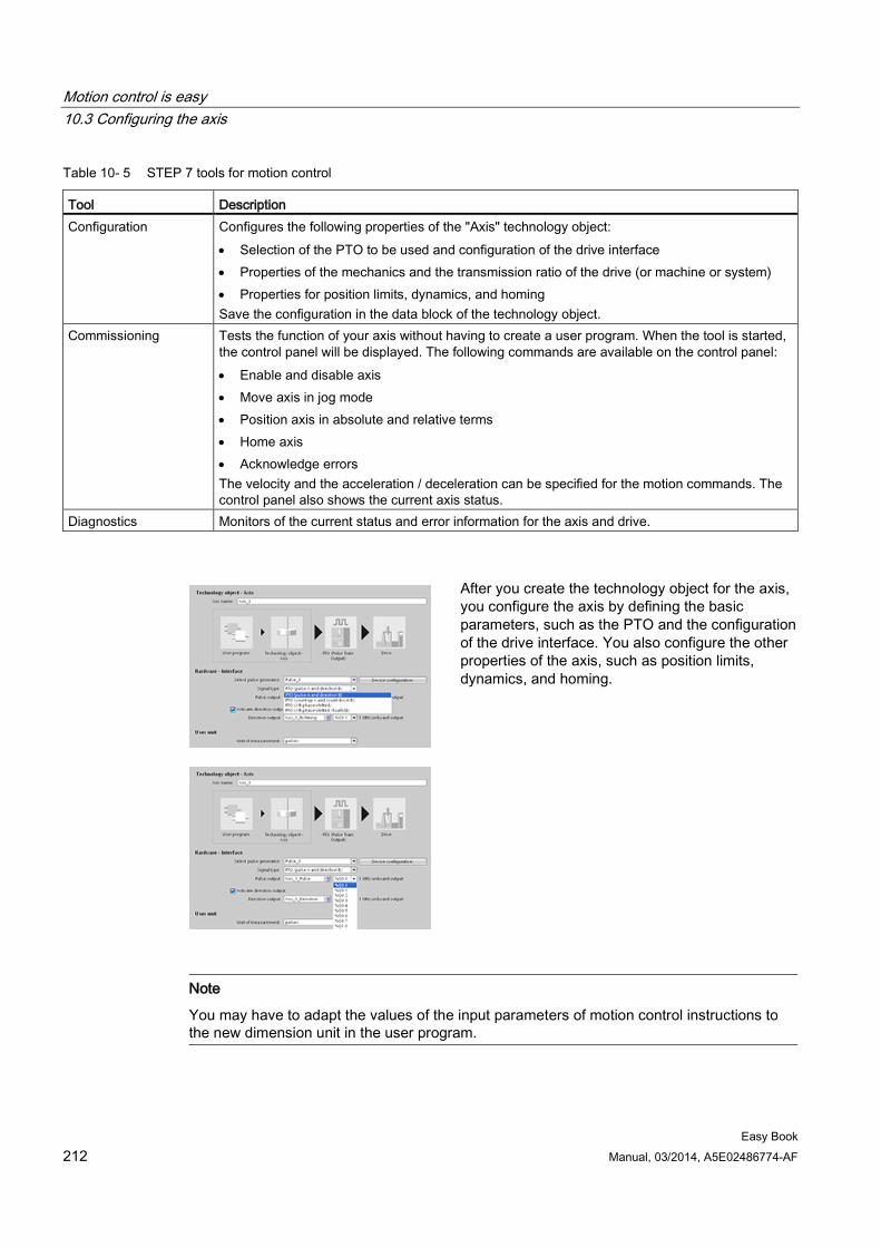
Motion control is easy 10.3 Configuring the axis
Easy Book 212 Manual, 03/2014, A5E02486774-AF
Table 10- 5 STEP 7 tools for motion control
Tool Description Configuration Configures the following properties of the "Axis" technology object:
• Selection of the PTO to be used and configuration of the drive interface • Properties of the mechanics and the transmission ratio of the drive (or machine or system) • Properties for position limits, dynamics, and homing Save the configuration in the data block of the technology object.
Commissioning Tests the function of your axis without having to create a user program. When the tool is started, the control panel will be displayed. The following commands are available on the control panel: • Enable and disable axis • Move axis in jog mode • Position axis in absolute and relative terms • Home axis • Acknowledge errors The velocity and the acceleration / deceleration can be specified for the motion commands. The control panel also shows the current axis status.
Diagnostics Monitors of the current status and error information for the axis and drive.
After you create the technology object for the axis, you configure the axis by defining the basic parameters, such as the PTO and the configuration of the drive interface. You also configure the other properties of the axis, such as position limits, dynamics, and homing.
Note
You may have to adapt the values of the input parameters of motion control instructions to the new dimension unit in the user program.
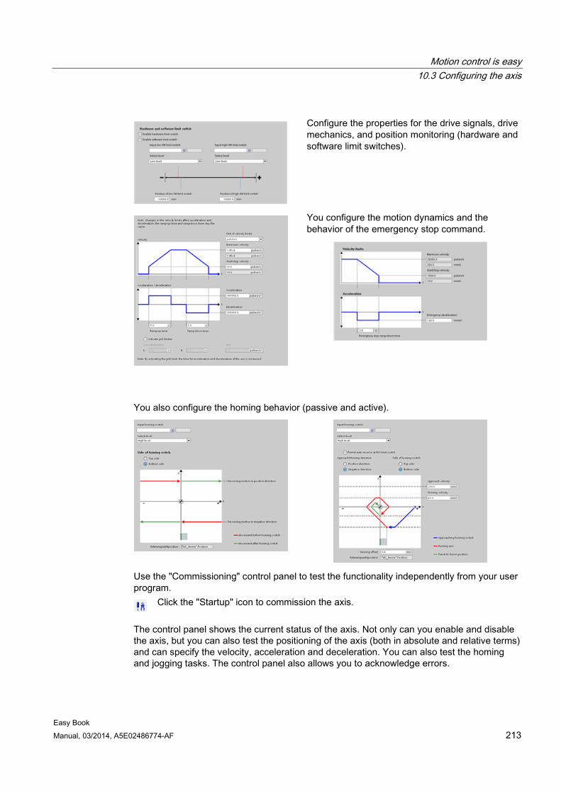
Motion control is easy 10.3 Configuring the axis
Easy Book Manual, 03/2014, A5E02486774-AF 213
Configure the properties for the drive signals, drive mechanics, and position monitoring (hardware and software limit switches).
You configure the motion dynamics and the behavior of the emergency stop command.
You also configure the homing behavior (passive and active).
Use the "Commissioning" control panel to test the functionality independently from your user program.
Click the "Startup" icon to commission the axis.
The control panel shows the current status of the axis. Not only can you enable and disable the axis, but you can also test the positioning of the axis (both in absolute and relative terms) and can specify the velocity, acceleration and deceleration. You can also test the homing and jogging tasks. The control panel also allows you to acknowledge errors.
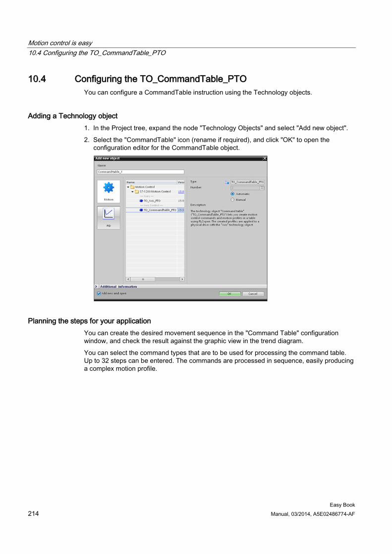
Motion control is easy 10.4 Configuring the TO_CommandTable_PTO
Easy Book 214 Manual, 03/2014, A5E02486774-AF
10.4 Configuring the TO_CommandTable_PTO You can configure a CommandTable instruction using the Technology objects.
Adding a Technology object 1. In the Project tree, expand the node "Technology Objects" and select "Add new object".
2. Select the "CommandTable" icon (rename if required), and click "OK" to open the configuration editor for the CommandTable object.
Planning the steps for your application You can create the desired movement sequence in the "Command Table" configuration window, and check the result against the graphic view in the trend diagram.
You can select the command types that are to be used for processing the command table. Up to 32 steps can be entered. The commands are processed in sequence, easily producing a complex motion profile.
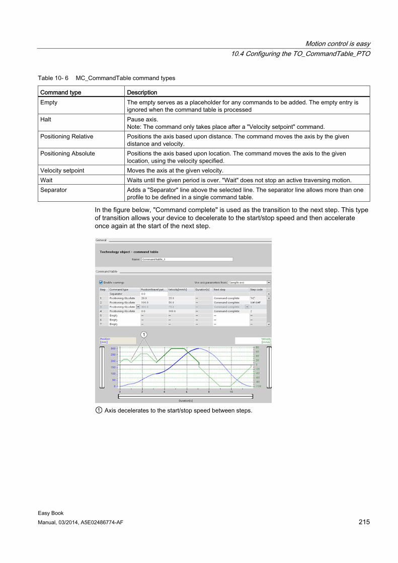
Motion control is easy 10.4 Configuring the TO_CommandTable_PTO
Easy Book Manual, 03/2014, A5E02486774-AF 215
Table 10- 6 MC_CommandTable command types
Command type Description Empty The empty serves as a placeholder for any commands to be added. The empty entry is
ignored when the command table is processed Halt Pause axis.
Note: The command only takes place after a "Velocity setpoint" command. Positioning Relative Positions the axis based upon distance. The command moves the axis by the given
distance and velocity. Positioning Absolute Positions the axis based upon location. The command moves the axis to the given
location, using the velocity specified. Velocity setpoint Moves the axis at the given velocity. Wait Waits until the given period is over. "Wait" does not stop an active traversing motion. Separator Adds a "Separator" line above the selected line. The separator line allows more than one
profile to be defined in a single command table.
In the figure below, "Command complete" is used as the transition to the next step. This type of transition allows your device to decelerate to the start/stop speed and then accelerate once again at the start of the next step.
① Axis decelerates to the start/stop speed between steps.
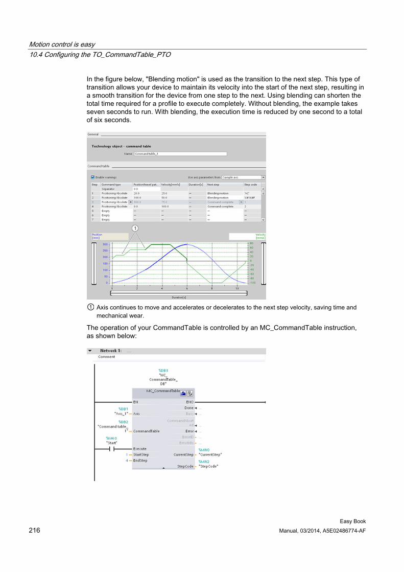
Motion control is easy 10.4 Configuring the TO_CommandTable_PTO
Easy Book 216 Manual, 03/2014, A5E02486774-AF
In the figure below, "Blending motion" is used as the transition to the next step. This type of transition allows your device to maintain its velocity into the start of the next step, resulting in a smooth transition for the device from one step to the next. Using blending can shorten the total time required for a profile to execute completely. Without blending, the example takes seven seconds to run. With blending, the execution time is reduced by one second to a total of six seconds.
① Axis continues to move and accelerates or decelerates to the next step velocity, saving time and
mechanical wear.
The operation of your CommandTable is controlled by an MC_CommandTable instruction, as shown below:
Motion control is easy 10.5 Motion control instructions
Easy Book Manual, 03/2014, A5E02486774-AF 217
10.5 Motion control instructions
10.5.1 MC instruction overview The motion control instructions use an associated technology data block and the dedicated PTO (pulse train outputs) of the CPU to control the motion on an axis.
● MC_Power (Page 217) enables and disables a motion control axis.
● MC_Reset (Page 221) resets all motion control errors. All motion control errors that can be acknowledged are acknowledged.
● MC_Home (Page 222) establishes the relationship between the axis control program and the axis mechanical positioning system.
● MC_Halt (Page 224) cancels all motion processes and causes the axis motion to stop. The stop position is not defined.
● MC_MoveAbsolute (Page 226) starts motion to an absolute position. The job ends when the target position is reached.
● MC_MoveRelative (Page 228) starts a positioning motion relative to the start position.
● MC_MoveVelocity (Page 230) causes the axis to travel with the specified speed.
● MC_MoveJog (Page 233) executes jog mode for testing and startup purposes.
● MC_CommandTable (Page 235) runs axis commands as a movement sequence.
● MC_ChangeDynamic (Page 237) changes Dynamics settings for the axis.
● MC_WriteParam (Page 239) writes a select number of parameters to change the functionality of the axis from the user program.
● MC_ReadParam (Page 241) reads a select number of parameters that indicate the current position, velocity, and so forth of the axis defined in the Axis input.
CPU firmware levels If you have an S7-1200 CPU with V4.0 firmware, select the V4.0 version of each motion instruction.
If you have an S7-1200 CPU with V3.0 or earlier firmware, select the applicable V3.0, V2.0, or V1.0 version of each motion instruction.
10.5.2 MC_Power (Release/block axis) instruction
Note
If the axis is switched off due to an error, it will be enabled again automatically after the error has been eliminated and acknowledged. This requires that the Enable input parameter has retained the value TRUE during this process.
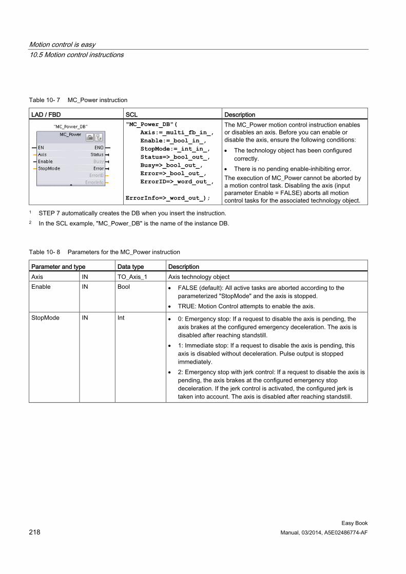
Motion control is easy 10.5 Motion control instructions
Easy Book 218 Manual, 03/2014, A5E02486774-AF
Table 10- 7 MC_Power instruction
LAD / FBD SCL Description
"MC_Power_DB"( Axis:=_multi_fb_in_, Enable:=_bool_in_, StopMode:=_int_in_, Status=>_bool_out_, Busy=>_bool_out_, Error=>_bool_out_, ErrorID=>_word_out_, ErrorInfo=>_word_out_);
The MC_Power motion control instruction enables or disables an axis. Before you can enable or disable the axis, ensure the following conditions: • The technology object has been configured
correctly. • There is no pending enable-inhibiting error. The execution of MC_Power cannot be aborted by a motion control task. Disabling the axis (input parameter Enable = FALSE) aborts all motion control tasks for the associated technology object.
1 STEP 7 automatically creates the DB when you insert the instruction. 2 In the SCL example, "MC_Power_DB" is the name of the instance DB.
Table 10- 8 Parameters for the MC_Power instruction
Parameter and type Data type Description Axis IN TO_Axis_1 Axis technology object Enable IN Bool • FALSE (default): All active tasks are aborted according to the
parameterized "StopMode" and the axis is stopped. • TRUE: Motion Control attempts to enable the axis.
StopMode IN Int • 0: Emergency stop: If a request to disable the axis is pending, the axis brakes at the configured emergency deceleration. The axis is disabled after reaching standstill.
• 1: Immediate stop: If a request to disable the axis is pending, this axis is disabled without deceleration. Pulse output is stopped immediately.
• 2: Emergency stop with jerk control: If a request to disable the axis is pending, the axis brakes at the configured emergency stop deceleration. If the jerk control is activated, the configured jerk is taken into account. The axis is disabled after reaching standstill.
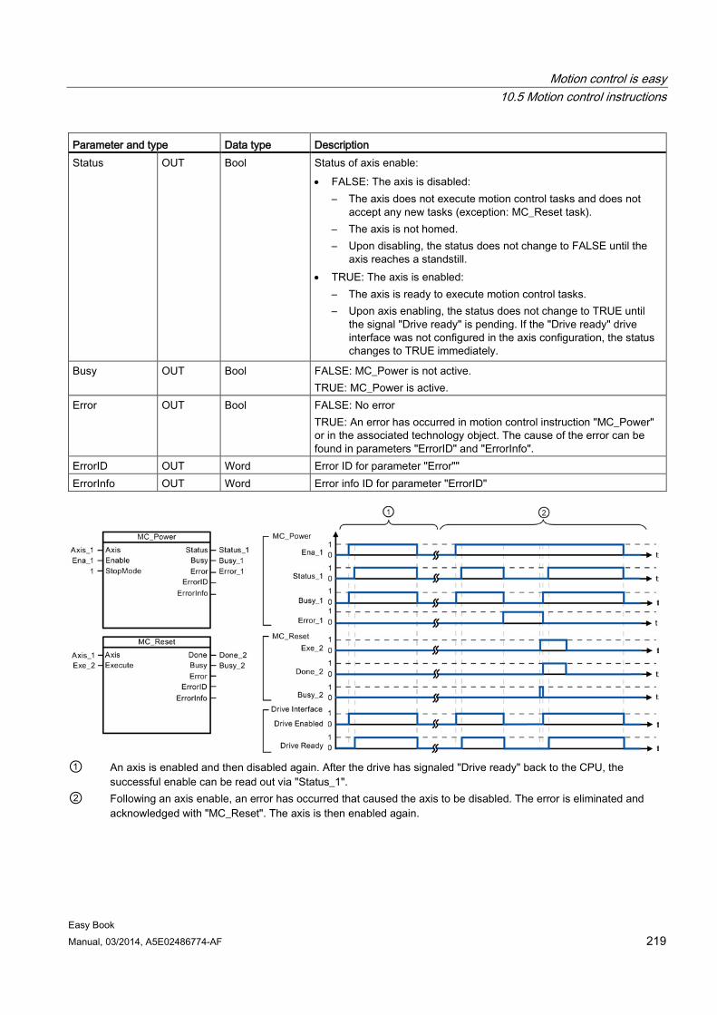
Motion control is easy 10.5 Motion control instructions
Easy Book Manual, 03/2014, A5E02486774-AF 219
Parameter and type Data type Description Status OUT Bool Status of axis enable:
• FALSE: The axis is disabled: – The axis does not execute motion control tasks and does not
accept any new tasks (exception: MC_Reset task). – The axis is not homed. – Upon disabling, the status does not change to FALSE until the
axis reaches a standstill. • TRUE: The axis is enabled:
– The axis is ready to execute motion control tasks. – Upon axis enabling, the status does not change to TRUE until
the signal "Drive ready" is pending. If the "Drive ready" drive interface was not configured in the axis configuration, the status changes to TRUE immediately.
Busy OUT Bool FALSE: MC_Power is not active. TRUE: MC_Power is active.
Error OUT Bool FALSE: No error TRUE: An error has occurred in motion control instruction "MC_Power" or in the associated technology object. The cause of the error can be found in parameters "ErrorID" and "ErrorInfo".
ErrorID OUT Word Error ID for parameter "Error"" ErrorInfo OUT Word Error info ID for parameter "ErrorID"
① An axis is enabled and then disabled again. After the drive has signaled "Drive ready" back to the CPU, the
successful enable can be read out via "Status_1". ② Following an axis enable, an error has occurred that caused the axis to be disabled. The error is eliminated and
acknowledged with "MC_Reset". The axis is then enabled again.
Motion control is easy 10.5 Motion control instructions
Easy Book 220 Manual, 03/2014, A5E02486774-AF
To enable an axis with configured drive interface, follow these steps:
1. Check the requirements indicated above.
2. Initialize input parameter "StopMode" with the desired value. Set input parameter "Enable" to TRUE.
The enable output for "Drive enabled" changes to TRUE to enable the power to the drive. The CPU waits for the "Drive ready" signal of the drive.
When the "Drive ready" signal is available at the configured ready input of the CPU, the axis becomes enabled. Output parameter "Status" and technology object tag <Axis name>.StatusBits.Enable indicates the value TRUE.
To enable an axis without configured drive interface, follow these steps:
1. Check the requirements indicated above.
2. Initialize input parameter "StopMode" with the desired value. Set input parameter "Enable" to TRUE. The axis is enabled. Output parameter "Status" and technology object tag <Axis name>.StatusBits.Enable indicate the value TRUE.
To disable an axis, follow these steps:
1. Bring the axis to a standstill.
You can identify when the axis is at a standstill in technology object tag <Axis name>.StatusBits.StandStill.
2. Set input parameter "Enable" to FALSE after standstill is reached.
3. If output parameters "Busy" and "Status" and technology object tag <Axis name>.StatusBits.Enable indicate the value FALSE, disabling of the axis is complete.
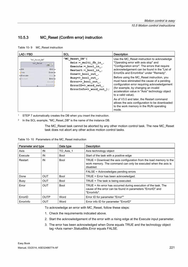
Motion control is easy 10.5 Motion control instructions
Easy Book Manual, 03/2014, A5E02486774-AF 221
10.5.3 MC_Reset (Confirm error) instruction
Table 10- 9 MC_Reset instruction
LAD / FBD SCL Description
"MC_Reset_DB"( Axis:=_multi_fb_in_, Execute:=_bool_in_, Restart:=_bool_in_, Done=>_bool_out_, Busy=>_bool_out_, Error=>_bool_out_, ErrorID=>_word_out_, ErrorInfo=>_word_out_);
Use the MC_Reset instruction to acknowledge "Operating error with axis stop" and "Configuration error". The errors that require acknowledgement can be found in the "List of ErrorIDs and ErrorInfos" under "Remedy". Before using the MC_Reset instruction, you must have eliminated the cause of a pending configuration error requiring acknowledgement (for example, by changing an invalid acceleration value in "Axis" technology object to a valid value). As of V3.0 and later, the Restart command allows the axis configuration to be downloaded to the work memory in the RUN operating mode.
1 STEP 7 automatically creates the DB when you insert the instruction. 2 In the SCL example, "MC_Reset_DB" is the name of the instance DB.
The MC_Reset task cannot be aborted by any other motion control task. The new MC_Reset task does not abort any other active motion control tasks.
Table 10- 10 Parameters of the MC_Reset instruction
Parameter and type Data type Description Axis IN TO_Axis_1 Axis technology object Execute IN Bool Start of the task with a positive edge Restart IN Bool TRUE = Download the axis configuration from the load memory to the
work memory. The command can only be executed when the axis is disabled. FALSE = Acknowledges pending errors
Done OUT Bool TRUE = Error has been acknowledged. Busy OUT Bool TRUE = The task is being executed. Error OUT Bool TRUE = An error has occurred during execution of the task. The
cause of the error can be found in parameters "ErrorID" and "ErrorInfo".
ErrorID OUTP Word Error ID for parameter "Error"" ErrorInfo OUT Word Error info ID for parameter "ErrorID"
To acknowledge an error with MC_Reset, follow these steps:
1. Check the requirements indicated above.
2. Start the acknowledgement of the error with a rising edge at the Execute input parameter.
3. The error has been acknowledged when Done equals TRUE and the technology object tag <Axis name>.StatusBits.Error equals FALSE.
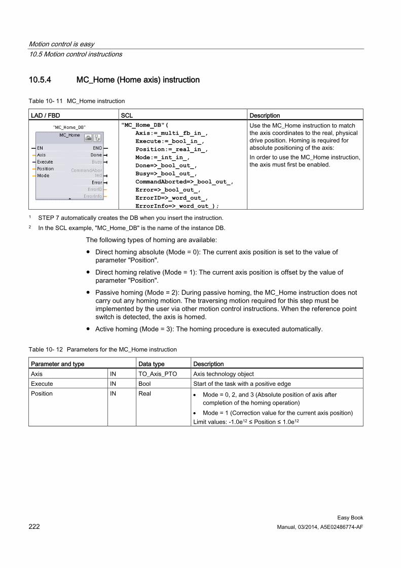
Motion control is easy 10.5 Motion control instructions
Easy Book 222 Manual, 03/2014, A5E02486774-AF
10.5.4 MC_Home (Home axis) instruction
Table 10- 11 MC_Home instruction
LAD / FBD SCL Description
"MC_Home_DB"( Axis:=_multi_fb_in_, Execute:=_bool_in_, Position:=_real_in_, Mode:=_int_in_, Done=>_bool_out_, Busy=>_bool_out_, CommandAborted=>_bool_out_, Error=>_bool_out_, ErrorID=>_word_out_, ErrorInfo=>_word_out_);
Use the MC_Home instruction to match the axis coordinates to the real, physical drive position. Homing is required for absolute positioning of the axis: In order to use the MC_Home instruction, the axis must first be enabled.
1 STEP 7 automatically creates the DB when you insert the instruction. 2 In the SCL example, "MC_Home_DB" is the name of the instance DB.
The following types of homing are available:
● Direct homing absolute (Mode = 0): The current axis position is set to the value of parameter "Position".
● Direct homing relative (Mode = 1): The current axis position is offset by the value of parameter "Position".
● Passive homing (Mode = 2): During passive homing, the MC_Home instruction does not carry out any homing motion. The traversing motion required for this step must be implemented by the user via other motion control instructions. When the reference point switch is detected, the axis is homed.
● Active homing (Mode = 3): The homing procedure is executed automatically.
Table 10- 12 Parameters for the MC_Home instruction
Parameter and type Data type Description Axis IN TO_Axis_PTO Axis technology object Execute IN Bool Start of the task with a positive edge Position IN Real • Mode = 0, 2, and 3 (Absolute position of axis after
completion of the homing operation) • Mode = 1 (Correction value for the current axis position) Limit values: -1.0e12 ≤ Position ≤ 1.0e12
Motion control is easy 10.5 Motion control instructions
Easy Book Manual, 03/2014, A5E02486774-AF 223
Parameter and type Data type Description Mode IN Int Homing mode
• 0: Direct homing absolute
New axis position is the position value of parameter "Position".
• 1: Direct homing relative
New axis position is the current axis position + position value of parameter "Position".
• 2: Passive homing
Homing according to the axis configuration. Following homing, the value of parameter "Position" is set as the new axis position.
• 3: Active homing
Reference point approach in accordance with the axis configuration. Following homing, the value of parameter "Position" is set as the new axis position.
Done OUT Bool TRUE = Task completed Busy OUT Bool TRUE = The task is being executed. CommandAborted OUT Bool TRUE = During execution the task was aborted by another
task. Error OUT Bool TRUE = An error has occurred during execution of the task.
The cause of the error can be found in parameters "ErrorID" and "ErrorInfo".
ErrorID OUT Word Error ID for parameter "Error"" ErrorInfo OUT Word Error info ID for parameter "ErrorID"
Note Axis homing is lost under the following conditions • Disabling of axis by the MC_Power instruction • Switchover between automatic control and manual control • Upon start of active homing (After successful completion of the homing operation, axis
homing is available again.) • After power-cycling the CPU • After CPU restart (RUN-to-STOP or STOP-to-RUN)
To home the axis, follow these steps:
1. Check the requirements indicated above.
2. Initialize the necessary input parameters with values, and start the homing operation with a rising edge at input parameter "Execute".
3. If output parameter "Done" and technology object tag <Axis name>.StatusBits.HomingDone indicate the value TRUE, homing is complete.
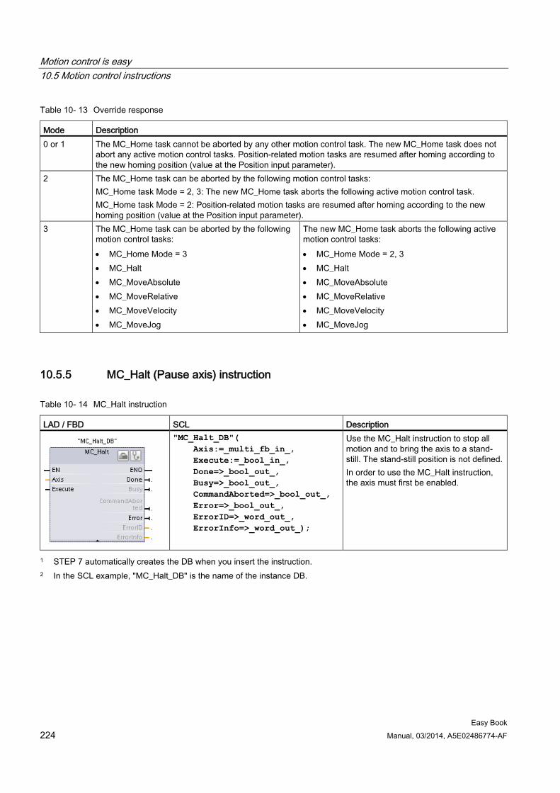
Motion control is easy 10.5 Motion control instructions
Easy Book 224 Manual, 03/2014, A5E02486774-AF
Table 10- 13 Override response
Mode Description 0 or 1 The MC_Home task cannot be aborted by any other motion control task. The new MC_Home task does not
abort any active motion control tasks. Position-related motion tasks are resumed after homing according to the new homing position (value at the Position input parameter).
2 The MC_Home task can be aborted by the following motion control tasks: MC_Home task Mode = 2, 3: The new MC_Home task aborts the following active motion control task. MC_Home task Mode = 2: Position-related motion tasks are resumed after homing according to the new homing position (value at the Position input parameter).
3 The MC_Home task can be aborted by the following motion control tasks: • MC_Home Mode = 3 • MC_Halt • MC_MoveAbsolute • MC_MoveRelative • MC_MoveVelocity • MC_MoveJog
The new MC_Home task aborts the following active motion control tasks: • MC_Home Mode = 2, 3 • MC_Halt • MC_MoveAbsolute • MC_MoveRelative • MC_MoveVelocity • MC_MoveJog
10.5.5 MC_Halt (Pause axis) instruction
Table 10- 14 MC_Halt instruction
LAD / FBD SCL Description
"MC_Halt_DB"( Axis:=_multi_fb_in_, Execute:=_bool_in_, Done=>_bool_out_, Busy=>_bool_out_, CommandAborted=>_bool_out_, Error=>_bool_out_, ErrorID=>_word_out_, ErrorInfo=>_word_out_);
Use the MC_Halt instruction to stop all motion and to bring the axis to a stand-still. The stand-still position is not defined. In order to use the MC_Halt instruction, the axis must first be enabled.
1 STEP 7 automatically creates the DB when you insert the instruction. 2 In the SCL example, "MC_Halt_DB" is the name of the instance DB.
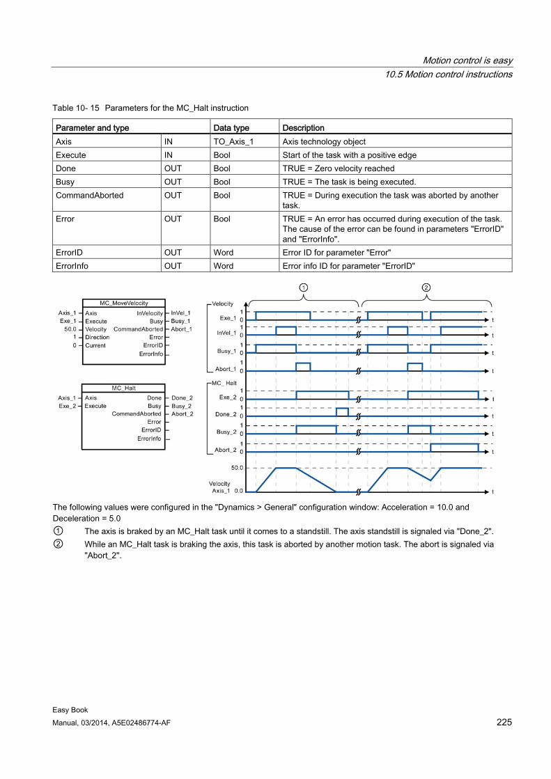
Motion control is easy 10.5 Motion control instructions
Easy Book Manual, 03/2014, A5E02486774-AF 225
Table 10- 15 Parameters for the MC_Halt instruction
Parameter and type Data type Description Axis IN TO_Axis_1 Axis technology object Execute IN Bool Start of the task with a positive edge Done OUT Bool TRUE = Zero velocity reached Busy OUT Bool TRUE = The task is being executed. CommandAborted OUT Bool TRUE = During execution the task was aborted by another
task. Error OUT Bool TRUE = An error has occurred during execution of the task.
The cause of the error can be found in parameters "ErrorID" and "ErrorInfo".
ErrorID OUT Word Error ID for parameter "Error" ErrorInfo OUT Word Error info ID for parameter "ErrorID"
The following values were configured in the "Dynamics > General" configuration window: Acceleration = 10.0 and Deceleration = 5.0 ① The axis is braked by an MC_Halt task until it comes to a standstill. The axis standstill is signaled via "Done_2". ② While an MC_Halt task is braking the axis, this task is aborted by another motion task. The abort is signaled via
"Abort_2".

Motion control is easy 10.5 Motion control instructions
Easy Book 226 Manual, 03/2014, A5E02486774-AF
Override response The MC_Halt task can be aborted by the following motion control tasks: • MC_Home Mode = 3 • MC_Halt • MC_MoveAbsolute • MC_MoveRelative • MC_MoveVelocity • MC_MoveJog
The new MC_Halt task aborts the following active motion control tasks: • MC_Home Mode = 3 • MC_Halt • MC_MoveAbsolute • MC_MoveRelative • MC_MoveVelocity • MC_MoveJog
10.5.6 MC_MoveAbsolute (Position axis absolutely) instruction
Table 10- 16 MC_MoveAbsolute instruction
LAD / FBD SCL Description
"MC_MoveAbsolute_DB"( Axis:=_multi_fb_in_, Execute:=_bool_in_, Position:=_real_in_, Velocity:=_real_in_, Done=>_bool_out_, Busy=>_bool_out_, CommandAborted=>_bool_out_, Error=>_bool_out_, ErrorID=>_word_out_, ErrorInfo=>_word_out_);
Use the MC_MoveAbsolute instruction to start a positioning motion of the axis to an absolute position. In order to use the MC_MoveAbsolute instruction, the axis must first be enabled and also must be homed.
1 STEP 7 automatically creates the DB when you insert the instruction. 2 In the SCL example, "MC_MoveAbsolute_DB" is the name of the instance DB.
Table 10- 17 Parameters for the MC_MoveAbsolute instruction
Parameter and type Data type Description Axis IN TO_Axis_1 Axis technology object Execute IN Bool Start of the task with a positive edge (Default value: False) Position IN Real Absolute target position (Default value: 0.0)
Limit values: -1.0e12 ≤ Position ≤ 1.0e12 Velocity IN Real Velocity of axis (Default value: 10.0)
This velocity is not always reached because of the configured acceleration and deceleration and the target position to be approached. Limit values: Start/stop velocity ≤ Velocity ≤ maximum velocity
Done OUT Bool TRUE = Absolute target position reached
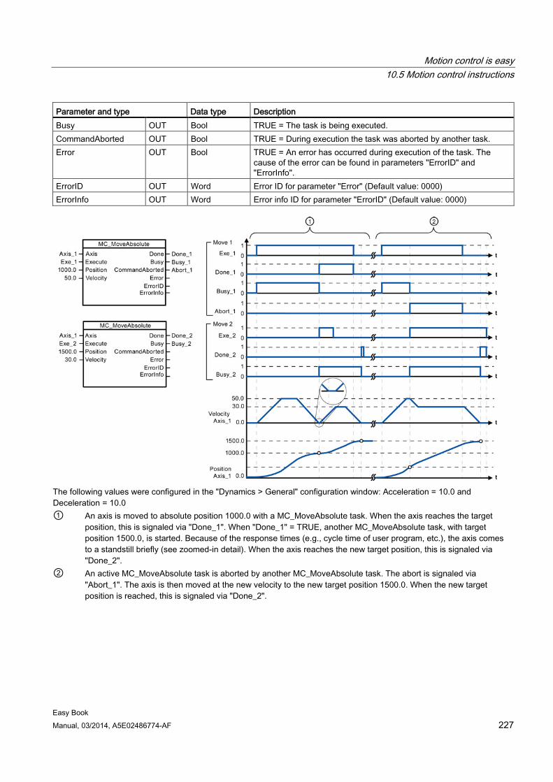
Motion control is easy 10.5 Motion control instructions
Easy Book Manual, 03/2014, A5E02486774-AF 227
Parameter and type Data type Description Busy OUT Bool TRUE = The task is being executed. CommandAborted OUT Bool TRUE = During execution the task was aborted by another task. Error OUT Bool TRUE = An error has occurred during execution of the task. The
cause of the error can be found in parameters "ErrorID" and "ErrorInfo".
ErrorID OUT Word Error ID for parameter "Error" (Default value: 0000) ErrorInfo OUT Word Error info ID for parameter "ErrorID" (Default value: 0000)
The following values were configured in the "Dynamics > General" configuration window: Acceleration = 10.0 and Deceleration = 10.0 ① An axis is moved to absolute position 1000.0 with a MC_MoveAbsolute task. When the axis reaches the target
position, this is signaled via "Done_1". When "Done_1" = TRUE, another MC_MoveAbsolute task, with target position 1500.0, is started. Because of the response times (e.g., cycle time of user program, etc.), the axis comes to a standstill briefly (see zoomed-in detail). When the axis reaches the new target position, this is signaled via "Done_2".
② An active MC_MoveAbsolute task is aborted by another MC_MoveAbsolute task. The abort is signaled via "Abort_1". The axis is then moved at the new velocity to the new target position 1500.0. When the new target position is reached, this is signaled via "Done_2".
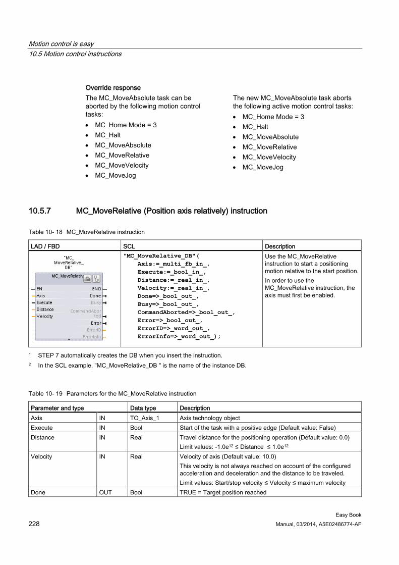
Motion control is easy 10.5 Motion control instructions
Easy Book 228 Manual, 03/2014, A5E02486774-AF
Override response The MC_MoveAbsolute task can be aborted by the following motion control tasks: • MC_Home Mode = 3 • MC_Halt • MC_MoveAbsolute • MC_MoveRelative • MC_MoveVelocity • MC_MoveJog
The new MC_MoveAbsolute task aborts the following active motion control tasks: • MC_Home Mode = 3 • MC_Halt • MC_MoveAbsolute • MC_MoveRelative • MC_MoveVelocity • MC_MoveJog
10.5.7 MC_MoveRelative (Position axis relatively) instruction
Table 10- 18 MC_MoveRelative instruction
LAD / FBD SCL Description
"MC_MoveRelative_DB"( Axis:=_multi_fb_in_, Execute:=_bool_in_, Distance:=_real_in_, Velocity:=_real_in_, Done=>_bool_out_, Busy=>_bool_out_, CommandAborted=>_bool_out_, Error=>_bool_out_, ErrorID=>_word_out_, ErrorInfo=>_word_out_);
Use the MC_MoveRelative instruction to start a positioning motion relative to the start position. In order to use the MC_MoveRelative instruction, the axis must first be enabled.
1 STEP 7 automatically creates the DB when you insert the instruction. 2 In the SCL example, "MC_MoveRelative_DB " is the name of the instance DB.
Table 10- 19 Parameters for the MC_MoveRelative instruction
Parameter and type Data type Description Axis IN TO_Axis_1 Axis technology object Execute IN Bool Start of the task with a positive edge (Default value: False) Distance IN Real Travel distance for the positioning operation (Default value: 0.0)
Limit values: -1.0e12 ≤ Distance ≤ 1.0e12 Velocity IN Real Velocity of axis (Default value: 10.0)
This velocity is not always reached on account of the configured acceleration and deceleration and the distance to be traveled. Limit values: Start/stop velocity ≤ Velocity ≤ maximum velocity
Done OUT Bool TRUE = Target position reached
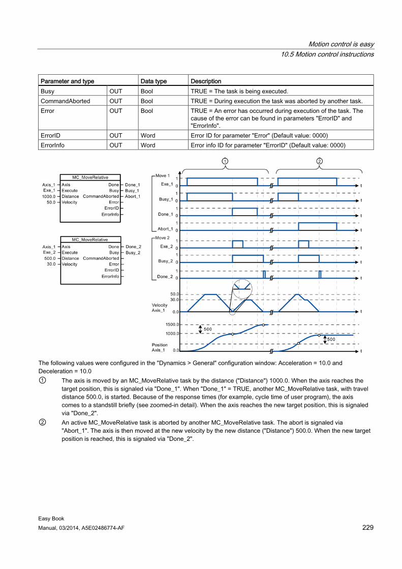
Motion control is easy 10.5 Motion control instructions
Easy Book Manual, 03/2014, A5E02486774-AF 229
Parameter and type Data type Description Busy OUT Bool TRUE = The task is being executed. CommandAborted OUT Bool TRUE = During execution the task was aborted by another task. Error OUT Bool TRUE = An error has occurred during execution of the task. The
cause of the error can be found in parameters "ErrorID" and "ErrorInfo".
ErrorID OUT Word Error ID for parameter "Error" (Default value: 0000) ErrorInfo OUT Word Error info ID for parameter "ErrorID" (Default value: 0000)
The following values were configured in the "Dynamics > General" configuration window: Acceleration = 10.0 and Deceleration = 10.0 ① The axis is moved by an MC_MoveRelative task by the distance ("Distance") 1000.0. When the axis reaches the
target position, this is signaled via "Done_1". When "Done_1" = TRUE, another MC_MoveRelative task, with travel distance 500.0, is started. Because of the response times (for example, cycle time of user program), the axis comes to a standstill briefly (see zoomed-in detail). When the axis reaches the new target position, this is signaled via "Done_2".
② An active MC_MoveRelative task is aborted by another MC_MoveRelative task. The abort is signaled via "Abort_1". The axis is then moved at the new velocity by the new distance ("Distance") 500.0. When the new target position is reached, this is signaled via "Done_2".
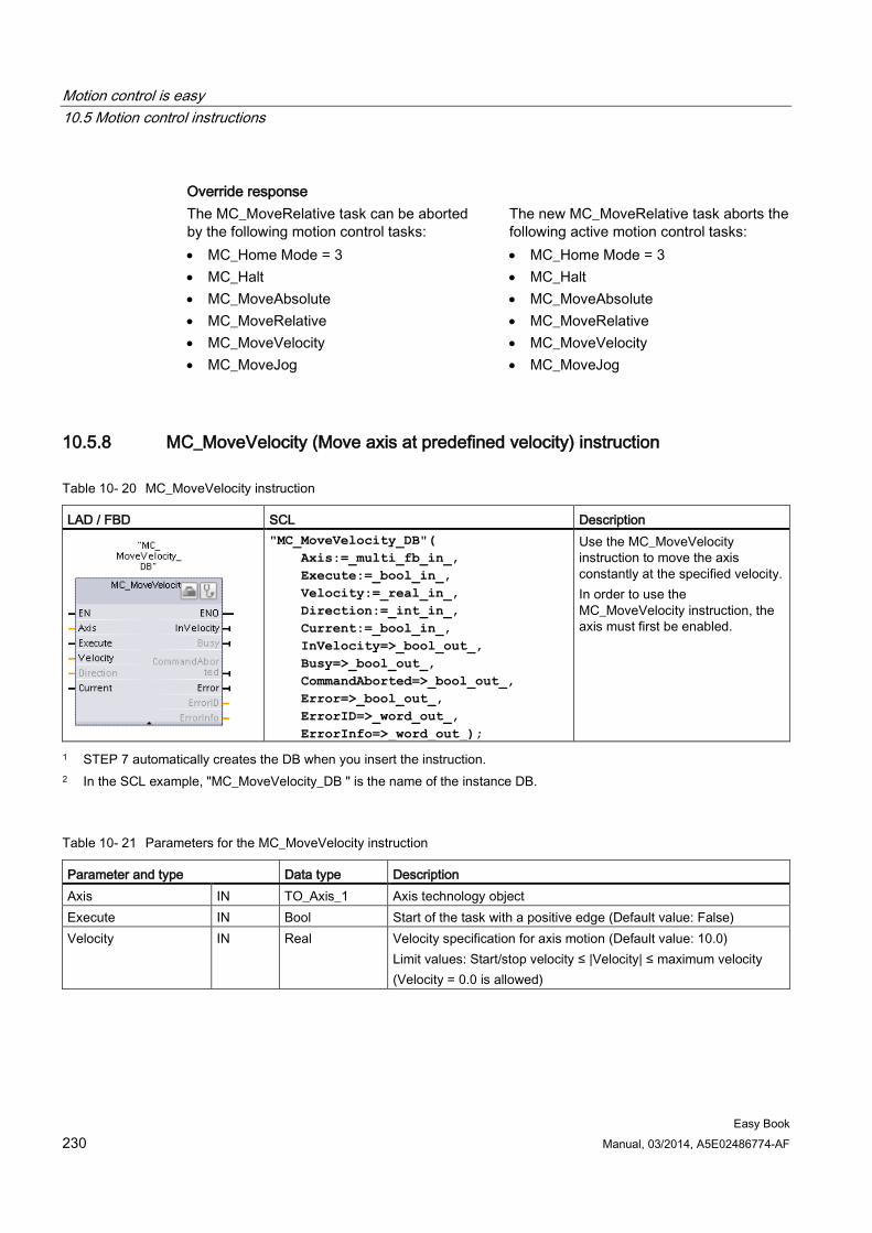
Motion control is easy 10.5 Motion control instructions
Easy Book 230 Manual, 03/2014, A5E02486774-AF
Override response The MC_MoveRelative task can be aborted by the following motion control tasks: • MC_Home Mode = 3 • MC_Halt • MC_MoveAbsolute • MC_MoveRelative • MC_MoveVelocity • MC_MoveJog
The new MC_MoveRelative task aborts the following active motion control tasks: • MC_Home Mode = 3 • MC_Halt • MC_MoveAbsolute • MC_MoveRelative • MC_MoveVelocity • MC_MoveJog
10.5.8 MC_MoveVelocity (Move axis at predefined velocity) instruction
Table 10- 20 MC_MoveVelocity instruction
LAD / FBD SCL Description
"MC_MoveVelocity_DB"( Axis:=_multi_fb_in_, Execute:=_bool_in_, Velocity:=_real_in_, Direction:=_int_in_, Current:=_bool_in_, InVelocity=>_bool_out_, Busy=>_bool_out_, CommandAborted=>_bool_out_, Error=>_bool_out_, ErrorID=>_word_out_, ErrorInfo=>_word_out_);
Use the MC_MoveVelocity instruction to move the axis constantly at the specified velocity. In order to use the MC_MoveVelocity instruction, the axis must first be enabled.
1 STEP 7 automatically creates the DB when you insert the instruction. 2 In the SCL example, "MC_MoveVelocity_DB " is the name of the instance DB.
Table 10- 21 Parameters for the MC_MoveVelocity instruction
Parameter and type Data type Description Axis IN TO_Axis_1 Axis technology object Execute IN Bool Start of the task with a positive edge (Default value: False) Velocity IN Real Velocity specification for axis motion (Default value: 10.0)
Limit values: Start/stop velocity ≤ |Velocity| ≤ maximum velocity (Velocity = 0.0 is allowed)
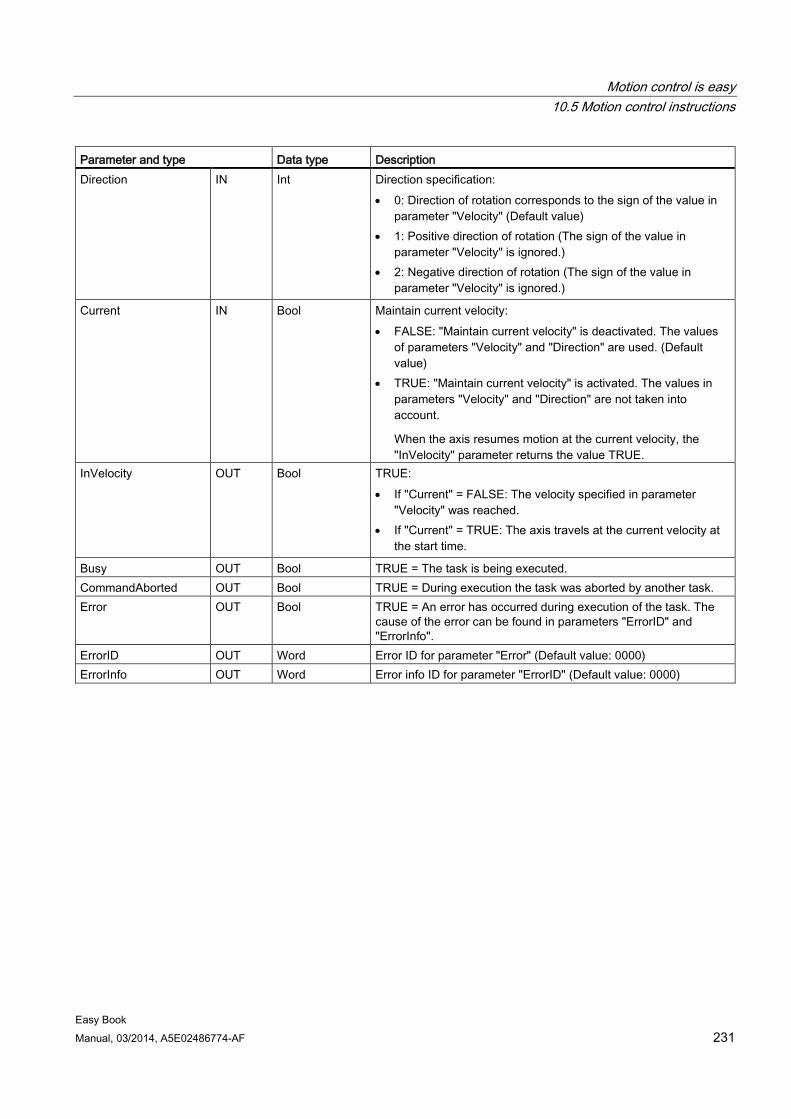
Motion control is easy 10.5 Motion control instructions
Easy Book Manual, 03/2014, A5E02486774-AF 231
Parameter and type Data type Description Direction IN Int Direction specification:
• 0: Direction of rotation corresponds to the sign of the value in parameter "Velocity" (Default value)
• 1: Positive direction of rotation (The sign of the value in parameter "Velocity" is ignored.)
• 2: Negative direction of rotation (The sign of the value in parameter "Velocity" is ignored.)
Current IN Bool Maintain current velocity: • FALSE: "Maintain current velocity" is deactivated. The values
of parameters "Velocity" and "Direction" are used. (Default value)
• TRUE: "Maintain current velocity" is activated. The values in parameters "Velocity" and "Direction" are not taken into account.
When the axis resumes motion at the current velocity, the "InVelocity" parameter returns the value TRUE.
InVelocity OUT Bool TRUE: • If "Current" = FALSE: The velocity specified in parameter
"Velocity" was reached. • If "Current" = TRUE: The axis travels at the current velocity at
the start time.
Busy OUT Bool TRUE = The task is being executed. CommandAborted OUT Bool TRUE = During execution the task was aborted by another task. Error OUT Bool TRUE = An error has occurred during execution of the task. The
cause of the error can be found in parameters "ErrorID" and "ErrorInfo".
ErrorID OUT Word Error ID for parameter "Error" (Default value: 0000) ErrorInfo OUT Word Error info ID for parameter "ErrorID" (Default value: 0000)
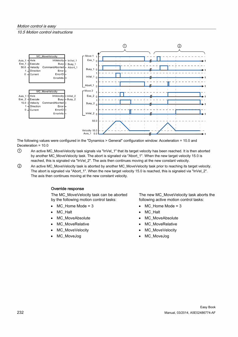
Motion control is easy 10.5 Motion control instructions
Easy Book 232 Manual, 03/2014, A5E02486774-AF
The following values were configured in the "Dynamics > General" configuration window: Acceleration = 10.0 and Deceleration = 10.0 ① An active MC_MoveVelocity task signals via "InVel_1" that its target velocity has been reached. It is then aborted
by another MC_MoveVelocity task. The abort is signaled via "Abort_1". When the new target velocity 15.0 is reached, this is signaled via "InVel_2". The axis then continues moving at the new constant velocity.
② An active MC_MoveVelocity task is aborted by another MC_MoveVelocity task prior to reaching its target velocity. The abort is signaled via "Abort_1". When the new target velocity 15.0 is reached, this is signaled via "InVel_2". The axis then continues moving at the new constant velocity.
Override response The MC_MoveVelocity task can be aborted by the following motion control tasks: • MC_Home Mode = 3 • MC_Halt • MC_MoveAbsolute • MC_MoveRelative • MC_MoveVelocity • MC_MoveJog
The new MC_MoveVelocity task aborts the following active motion control tasks: • MC_Home Mode = 3 • MC_Halt • MC_MoveAbsolute • MC_MoveRelative • MC_MoveVelocity • MC_MoveJog
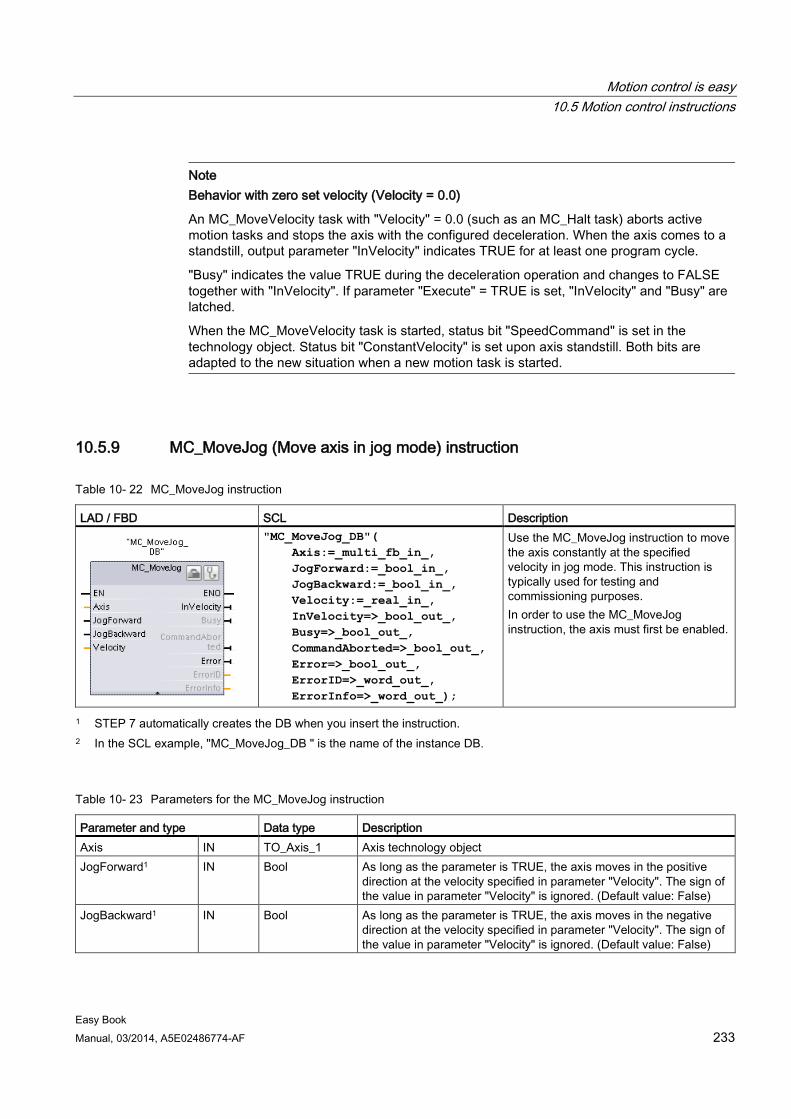
Motion control is easy 10.5 Motion control instructions
Easy Book Manual, 03/2014, A5E02486774-AF 233
Note Behavior with zero set velocity (Velocity = 0.0)
An MC_MoveVelocity task with "Velocity" = 0.0 (such as an MC_Halt task) aborts active motion tasks and stops the axis with the configured deceleration. When the axis comes to a standstill, output parameter "InVelocity" indicates TRUE for at least one program cycle.
"Busy" indicates the value TRUE during the deceleration operation and changes to FALSE together with "InVelocity". If parameter "Execute" = TRUE is set, "InVelocity" and "Busy" are latched.
When the MC_MoveVelocity task is started, status bit "SpeedCommand" is set in the technology object. Status bit "ConstantVelocity" is set upon axis standstill. Both bits are adapted to the new situation when a new motion task is started.
10.5.9 MC_MoveJog (Move axis in jog mode) instruction
Table 10- 22 MC_MoveJog instruction
LAD / FBD SCL Description
"MC_MoveJog_DB"( Axis:=_multi_fb_in_, JogForward:=_bool_in_, JogBackward:=_bool_in_, Velocity:=_real_in_, InVelocity=>_bool_out_, Busy=>_bool_out_, CommandAborted=>_bool_out_, Error=>_bool_out_, ErrorID=>_word_out_, ErrorInfo=>_word_out_);
Use the MC_MoveJog instruction to move the axis constantly at the specified velocity in jog mode. This instruction is typically used for testing and commissioning purposes. In order to use the MC_MoveJog instruction, the axis must first be enabled.
1 STEP 7 automatically creates the DB when you insert the instruction. 2 In the SCL example, "MC_MoveJog_DB " is the name of the instance DB.
Table 10- 23 Parameters for the MC_MoveJog instruction
Parameter and type Data type Description Axis IN TO_Axis_1 Axis technology object JogForward1 IN Bool As long as the parameter is TRUE, the axis moves in the positive
direction at the velocity specified in parameter "Velocity". The sign of the value in parameter "Velocity" is ignored. (Default value: False)
JogBackward1 IN Bool As long as the parameter is TRUE, the axis moves in the negative direction at the velocity specified in parameter "Velocity". The sign of the value in parameter "Velocity" is ignored. (Default value: False)
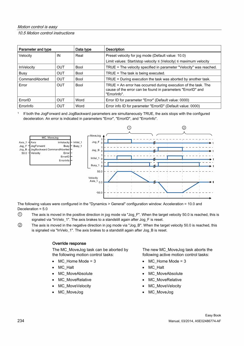
Motion control is easy 10.5 Motion control instructions
Easy Book 234 Manual, 03/2014, A5E02486774-AF
Parameter and type Data type Description Velocity IN Real Preset velocity for jog mode (Default value: 10.0)
Limit values: Start/stop velocity ≤ |Velocity| ≤ maximum velocity InVelocity OUT Bool TRUE = The velocity specified in parameter "Velocity" was reached. Busy OUT Bool TRUE = The task is being executed. CommandAborted OUT Bool TRUE = During execution the task was aborted by another task. Error OUT Bool TRUE = An error has occurred during execution of the task. The
cause of the error can be found in parameters "ErrorID" and "ErrorInfo".
ErrorID OUT Word Error ID for parameter "Error" (Default value: 0000) ErrorInfo OUT Word Error info ID for parameter "ErrorID" (Default value: 0000) 1 If both the JogForward and JogBackward parameters are simultaneously TRUE, the axis stops with the configured
deceleration. An error is indicated in parameters "Error", "ErrorID", and "ErrorInfo".
The following values were configured in the "Dynamics > General" configuration window: Acceleration = 10.0 and Deceleration = 5.0 ① The axis is moved in the positive direction in jog mode via "Jog_F". When the target velocity 50.0 is reached, this is
signaled via "InVelo_1". The axis brakes to a standstill again after Jog_F is reset. ② The axis is moved in the negative direction in jog mode via "Jog_B". When the target velocity 50.0 is reached, this
is signaled via "InVelo_1". The axis brakes to a standstill again after Jog_B is reset.
Override response The MC_MoveJog task can be aborted by the following motion control tasks: • MC_Home Mode = 3 • MC_Halt • MC_MoveAbsolute • MC_MoveRelative • MC_MoveVelocity • MC_MoveJog
The new MC_MoveJog task aborts the following active motion control tasks: • MC_Home Mode = 3 • MC_Halt • MC_MoveAbsolute • MC_MoveRelative • MC_MoveVelocity • MC_MoveJog
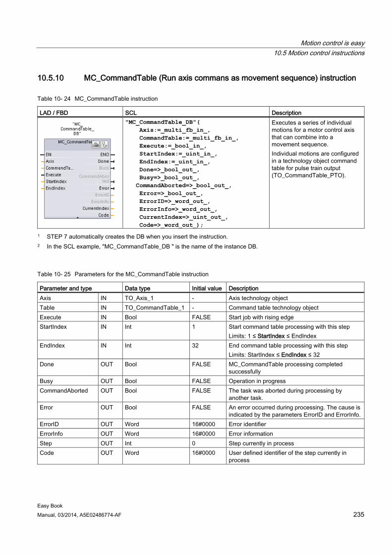
Motion control is easy 10.5 Motion control instructions
Easy Book Manual, 03/2014, A5E02486774-AF 235
10.5.10 MC_CommandTable (Run axis commans as movement sequence) instruction
Table 10- 24 MC_CommandTable instruction
LAD / FBD SCL Description
"MC_CommandTable_DB"( Axis:=_multi_fb_in_, CommandTable:=_multi_fb_in_, Execute:=_bool_in_, StartIndex:=_uint_in_, EndIndex:=_uint_in_, Done=>_bool_out_, Busy=>_bool_out_, CommandAborted=>_bool_out_, Error=>_bool_out_, ErrorID=>_word_out_, ErrorInfo=>_word_out_, CurrentIndex=>_uint_out_, Code=>_word_out_);
Executes a series of individual motions for a motor control axis that can combine into a movement sequence. Individual motions are configured in a technology object command table for pulse train output (TO_CommandTable_PTO).
1 STEP 7 automatically creates the DB when you insert the instruction. 2 In the SCL example, "MC_CommandTable_DB " is the name of the instance DB.
Table 10- 25 Parameters for the MC_CommandTable instruction
Parameter and type Data type Initial value Description Axis IN TO_Axis_1 - Axis technology object Table IN TO_CommandTable_1 - Command table technology object Execute IN Bool FALSE Start job with rising edge StartIndex IN Int 1 Start command table processing with this step
Limits: 1 ≤ StartIndex ≤ EndIndex EndIndex IN Int 32 End command table processing with this step
Limits: StartIndex ≤ EndIndex ≤ 32 Done OUT Bool FALSE MC_CommandTable processing completed
successfully Busy OUT Bool FALSE Operation in progress CommandAborted OUT Bool FALSE The task was aborted during processing by
another task. Error OUT Bool FALSE An error occurred during processing. The cause is
indicated by the parameters ErrorID and ErrorInfo. ErrorID OUT Word 16#0000 Error identifier ErrorInfo OUT Word 16#0000 Error information Step OUT Int 0 Step currently in process Code OUT Word 16#0000 User defined identifier of the step currently in
process
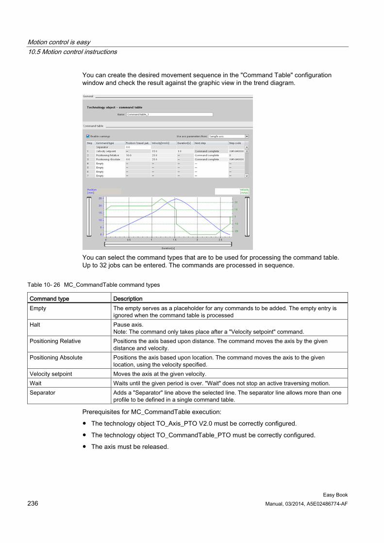
Motion control is easy 10.5 Motion control instructions
Easy Book 236 Manual, 03/2014, A5E02486774-AF
You can create the desired movement sequence in the "Command Table" configuration window and check the result against the graphic view in the trend diagram.
You can select the command types that are to be used for processing the command table. Up to 32 jobs can be entered. The commands are processed in sequence.
Table 10- 26 MC_CommandTable command types
Command type Description Empty The empty serves as a placeholder for any commands to be added. The empty entry is
ignored when the command table is processed Halt Pause axis.
Note: The command only takes place after a "Velocity setpoint" command. Positioning Relative Positions the axis based upon distance. The command moves the axis by the given
distance and velocity. Positioning Absolute Positions the axis based upon location. The command moves the axis to the given
location, using the velocity specified. Velocity setpoint Moves the axis at the given velocity. Wait Waits until the given period is over. "Wait" does not stop an active traversing motion. Separator Adds a "Separator" line above the selected line. The separator line allows more than one
profile to be defined in a single command table.
Prerequisites for MC_CommandTable execution:
● The technology object TO_Axis_PTO V2.0 must be correctly configured.
● The technology object TO_CommandTable_PTO must be correctly configured.
● The axis must be released.
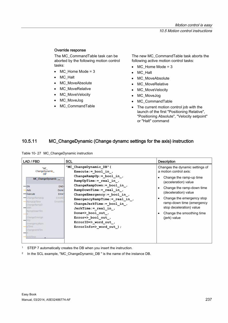
Motion control is easy 10.5 Motion control instructions
Easy Book Manual, 03/2014, A5E02486774-AF 237
Override response The MC_CommandTable task can be aborted by the following motion control tasks: • MC_Home Mode = 3 • MC_Halt • MC_MoveAbsolute • MC_MoveRelative • MC_MoveVelocity • MC_MoveJog • MC_CommandTable
The new MC_CommandTable task aborts the following active motion control tasks: • MC_Home Mode = 3 • MC_Halt • MC_MoveAbsolute • MC_MoveRelative • MC_MoveVelocity • MC_MoveJog • MC_CommandTable • The current motion control job with the
launch of the first "Positioning Relative", "Positioning Absolute", "Velocity setpoint" or "Halt" command
10.5.11 MC_ChangeDynamic (Change dynamc settings for the axis) instruction
Table 10- 27 MC_ChangeDynamic instruction
LAD / FBD SCL Description
"MC_ChangeDynamic_DB"( Execute:=_bool_in_, ChangeRampUp:=_bool_in_, RampUpTime:=_real_in_, ChangeRampDown:=_bool_in_, RampDownTime:=_real_in_, ChangeEmergency:=_bool_in_, EmergencyRampTime:=_real_in_, ChangeJerkTime:=_bool_in_, JerkTime:=_real_in_, Done=>_bool_out_, Error=>_bool_out_, ErrorID=>_word_out_, ErrorInfo=>_word_out_);
Changes the dynamic settings of a motion control axis: • Change the ramp-up time
(acceleration) value • Change the ramp-down time
(deceleration) value • Change the emergency stop
ramp-down time (emergency stop deceleration) value
• Change the smoothing time (jerk) value
1 STEP 7 automatically creates the DB when you insert the instruction. 2 In the SCL example, "MC_ChangeDynamic_DB " is the name of the instance DB.
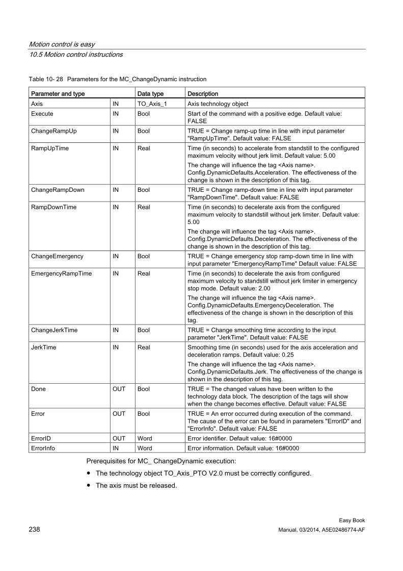
Motion control is easy 10.5 Motion control instructions
Easy Book 238 Manual, 03/2014, A5E02486774-AF
Table 10- 28 Parameters for the MC_ChangeDynamic instruction
Parameter and type Data type Description Axis IN TO_Axis_1 Axis technology object Execute IN Bool Start of the command with a positive edge. Default value:
FALSE ChangeRampUp IN Bool TRUE = Change ramp-up time in line with input parameter
"RampUpTime". Default value: FALSE RampUpTime IN Real Time (in seconds) to accelerate from standstill to the configured
maximum velocity without jerk limit. Default value: 5.00 The change will influence the tag <Axis name>. Config.DynamicDefaults.Acceleration. The effectiveness of the change is shown in the description of this tag.
ChangeRampDown IN Bool TRUE = Change ramp-down time in line with input parameter "RampDownTime". Default value: FALSE
RampDownTime IN Real Time (in seconds) to decelerate axis from the configured maximum velocity to standstill without jerk limiter. Default value: 5.00 The change will influence the tag <Axis name>. Config.DynamicDefaults.Deceleration. The effectiveness of the change is shown in the description of this tag.
ChangeEmergency IN Bool TRUE = Change emergency stop ramp-down time in line with input parameter "EmergencyRampTime" Default value: FALSE
EmergencyRampTime IN Real Time (in seconds) to decelerate the axis from configured maximum velocity to standstill without jerk limiter in emergency stop mode. Default value: 2.00 The change will influence the tag <Axis name>. Config.DynamicDefaults.EmergencyDeceleration. The effectiveness of the change is shown in the description of this tag.
ChangeJerkTime IN Bool TRUE = Change smoothing time according to the input parameter "JerkTime". Default value: FALSE
JerkTime IN Real Smoothing time (in seconds) used for the axis acceleration and deceleration ramps. Default value: 0.25 The change will influence the tag <Axis name>. Config.DynamicDefaults.Jerk. The effectiveness of the change is shown in the description of this tag.
Done OUT Bool TRUE = The changed values have been written to the technology data block. The description of the tags will show when the change becomes effective. Default value: FALSE
Error OUT Bool TRUE = An error occurred during execution of the command. The cause of the error can be found in parameters "ErrorID" and "ErrorInfo". Default value: FALSE
ErrorID OUT Word Error identifier. Default value: 16#0000 ErrorInfo IN Word Error information. Default value: 16#0000
Prerequisites for MC_ ChangeDynamic execution:
● The technology object TO_Axis_PTO V2.0 must be correctly configured.
● The axis must be released.
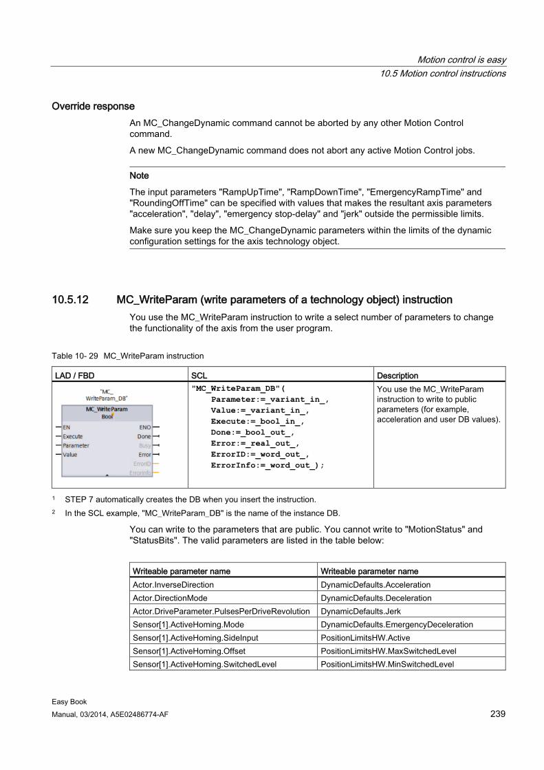
Motion control is easy 10.5 Motion control instructions
Easy Book Manual, 03/2014, A5E02486774-AF 239
Override response An MC_ChangeDynamic command cannot be aborted by any other Motion Control command.
A new MC_ChangeDynamic command does not abort any active Motion Control jobs.
Note
The input parameters "RampUpTime", "RampDownTime", "EmergencyRampTime" and "RoundingOffTime" can be specified with values that makes the resultant axis parameters "acceleration", "delay", "emergency stop-delay" and "jerk" outside the permissible limits.
Make sure you keep the MC_ChangeDynamic parameters within the limits of the dynamic configuration settings for the axis technology object.
10.5.12 MC_WriteParam (write parameters of a technology object) instruction You use the MC_WriteParam instruction to write a select number of parameters to change the functionality of the axis from the user program.
Table 10- 29 MC_WriteParam instruction
LAD / FBD SCL Description
"MC_WriteParam_DB"( Parameter:=_variant_in_, Value:=_variant_in_, Execute:=_bool_in_, Done:=_bool_out_, Error:=_real_out_, ErrorID:=_word_out_, ErrorInfo:=_word_out_);
You use the MC_WriteParam instruction to write to public parameters (for example, acceleration and user DB values).
1 STEP 7 automatically creates the DB when you insert the instruction. 2 In the SCL example, "MC_WriteParam_DB" is the name of the instance DB.
You can write to the parameters that are public. You cannot write to "MotionStatus" and "StatusBits". The valid parameters are listed in the table below:
Writeable parameter name Writeable parameter name Actor.InverseDirection DynamicDefaults.Acceleration Actor.DirectionMode DynamicDefaults.Deceleration Actor.DriveParameter.PulsesPerDriveRevolution DynamicDefaults.Jerk Sensor[1].ActiveHoming.Mode DynamicDefaults.EmergencyDeceleration Sensor[1].ActiveHoming.SideInput PositionLimitsHW.Active Sensor[1].ActiveHoming.Offset PositionLimitsHW.MaxSwitchedLevel Sensor[1].ActiveHoming.SwitchedLevel PositionLimitsHW.MinSwitchedLevel
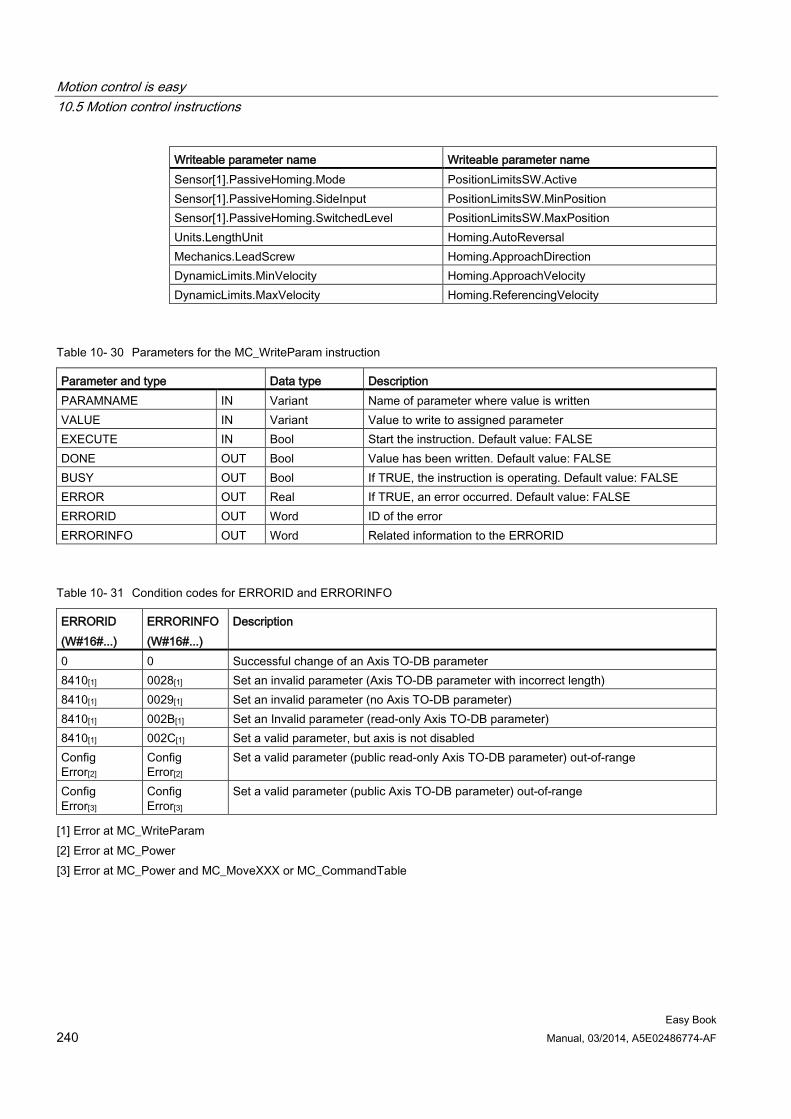
Motion control is easy 10.5 Motion control instructions
Easy Book 240 Manual, 03/2014, A5E02486774-AF
Writeable parameter name Writeable parameter name Sensor[1].PassiveHoming.Mode PositionLimitsSW.Active Sensor[1].PassiveHoming.SideInput PositionLimitsSW.MinPosition Sensor[1].PassiveHoming.SwitchedLevel PositionLimitsSW.MaxPosition Units.LengthUnit Homing.AutoReversal Mechanics.LeadScrew Homing.ApproachDirection DynamicLimits.MinVelocity Homing.ApproachVelocity DynamicLimits.MaxVelocity Homing.ReferencingVelocity
Table 10- 30 Parameters for the MC_WriteParam instruction
Parameter and type Data type Description PARAMNAME IN Variant Name of parameter where value is written VALUE IN Variant Value to write to assigned parameter EXECUTE IN Bool Start the instruction. Default value: FALSE DONE OUT Bool Value has been written. Default value: FALSE BUSY OUT Bool If TRUE, the instruction is operating. Default value: FALSE ERROR OUT Real If TRUE, an error occurred. Default value: FALSE ERRORID OUT Word ID of the error ERRORINFO OUT Word Related information to the ERRORID
Table 10- 31 Condition codes for ERRORID and ERRORINFO
ERRORID (W#16#...)
ERRORINFO (W#16#...)
Description
0 0 Successful change of an Axis TO-DB parameter 8410[1] 0028[1] Set an invalid parameter (Axis TO-DB parameter with incorrect length) 8410[1] 0029[1] Set an invalid parameter (no Axis TO-DB parameter) 8410[1] 002B[1] Set an Invalid parameter (read-only Axis TO-DB parameter) 8410[1] 002C[1] Set a valid parameter, but axis is not disabled Config Error[2]
Config Error[2]
Set a valid parameter (public read-only Axis TO-DB parameter) out-of-range
Config Error[3]
Config Error[3]
Set a valid parameter (public Axis TO-DB parameter) out-of-range
[1] Error at MC_WriteParam [2] Error at MC_Power [3] Error at MC_Power and MC_MoveXXX or MC_CommandTable
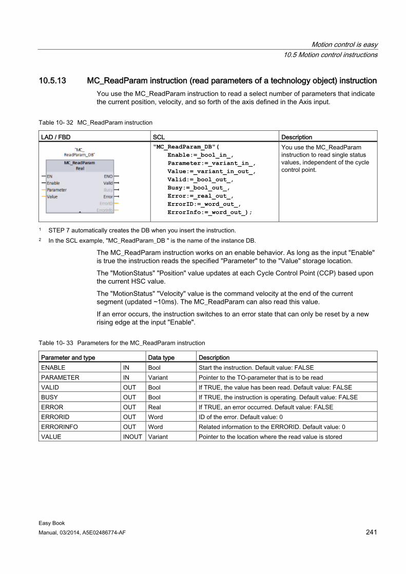
Motion control is easy 10.5 Motion control instructions
Easy Book Manual, 03/2014, A5E02486774-AF 241
10.5.13 MC_ReadParam instruction (read parameters of a technology object) instruction You use the MC_ReadParam instruction to read a select number of parameters that indicate the current position, velocity, and so forth of the axis defined in the Axis input.
Table 10- 32 MC_ReadParam instruction
LAD / FBD SCL Description
"MC_ReadParam_DB"( Enable:=_bool_in_, Parameter:=_variant_in_, Value:=_variant_in_out_, Valid:=_bool_out_, Busy:=_bool_out_, Error:=_real_out_, ErrorID:=_word_out_, ErrorInfo:=_word_out_);
You use the MC_ReadParam instruction to read single status values, independent of the cycle control point.
1 STEP 7 automatically creates the DB when you insert the instruction. 2 In the SCL example, "MC_ReadParam_DB " is the name of the instance DB.
The MC_ReadParam instruction works on an enable behavior. As long as the input "Enable" is true the instruction reads the specified "Parameter" to the "Value" storage location.
The "MotionStatus" "Position" value updates at each Cycle Control Point (CCP) based upon the current HSC value.
The "MotionStatus" "Velocity" value is the command velocity at the end of the current segment (updated ~10ms). The MC_ReadParam can also read this value.
If an error occurs, the instruction switches to an error state that can only be reset by a new rising edge at the input "Enable".
Table 10- 33 Parameters for the MC_ReadParam instruction
Parameter and type Data type Description ENABLE IN Bool Start the instruction. Default value: FALSE PARAMETER IN Variant Pointer to the TO-parameter that is to be read VALID OUT Bool If TRUE, the value has been read. Default value: FALSE BUSY OUT Bool If TRUE, the instruction is operating. Default value: FALSE ERROR OUT Real If TRUE, an error occurred. Default value: FALSE ERRORID OUT Word ID of the error. Default value: 0 ERRORINFO OUT Word Related information to the ERRORID. Default value: 0 VALUE INOUT Variant Pointer to the location where the read value is stored
Motion control is easy 10.6 Operation of motion control for S7-1200
Easy Book 242 Manual, 03/2014, A5E02486774-AF
Table 10- 34 Condition codes for ERRORID and ERRORINFO
ERRORID (W#16#...)
ERRORINFO (W#16#...)
Description
0 0 Successful read of a parameter 8410 0028 Invalid parameter (incorrect length) 8410 0029 Invalid parameter (no TO-DB) 8410 0030 Invalid parameter (not readable) 8411 0032 Invalid parameter (wrong value)
TO parameters The axis "MotionStatus" consists of four values. You will want to monitor changes in these values, which can be read while the program is running:
Variable name Data type Readable through
MC_ReadParam MotionStatus: Structure No
• Position REAL Yes
• Velocity REAL Yes
• Distance REAL Yes
• TargetPosition REAL Yes
10.6 Operation of motion control for S7-1200
10.6.1 CPU outputs used for motion control The CPU provides four pulse output generators. Each pulse output generator provides one pulse output and one direction output for controlling a stepper motor drive or a servo motor drive with pulse interface. The pulse output provides the drive with the pulses required for motor motion. The direction output controls the travel direction of the drive.
The PTO output generates a square wave output of variable frequency. Pulse generation is controlled by configuration and execution information supplied through H/W configuration and/or SFCs/SFBs.
Based upon the user’s selection while the CPU is in RUN mode, either the values stored in the image register or the pulse generator outputs drive the digital outputs. In STOP mode, the PTO generator does not control the outputs.
Onboard CPU outputs and outputs of a signal board can be used as pulse and direction outputs. You select between onboard CPU outputs and outputs of the signal board during device configuration under Pulse generators (PTO/PWM) on the "Properties" tab. Only PTO (Pulse Train Output) applies to motion control.
Motion control is easy 10.6 Operation of motion control for S7-1200
Easy Book Manual, 03/2014, A5E02486774-AF 243
The table below shows the default I/O assignments; however, the four pulse generators can be configured to any digital output.
Note Pulse-train outputs cannot be used by other instructions in the user program.
When you configure the outputs of the CPU or signal board as pulse generators (for use with the PWM or motion control instructions), the corresponding output addresses no longer control the outputs. If your user program writes a value to an output used as a pulse generator, the CPU does not write that value to the physical output.
Note PTO direction outputs can be freed for use elsewhere in your program.
Each PTO requires the assignment of two outputs: one as a pulse output and one as a direction output. You can use just the pulse output and not the direction output. You can then free the direction output for other purposes in your user program. The output cannot be used for both the PTO direction output and in the user program, simultaneously.
Table 10- 35 Default address assignments of the pulse and direction outputs
Usage of outputs for motion control Pulse Direction
PTO1 Built-in I/O Q0.0 Q0.1
SB I/O Q4.0 Q4.1 PTO2
Built-in I/O Q0.2 Q0.3 SB I/O Q4.2 Q4.3
PTO3 Built-in I/O Q0.41 Q0.51
SB I/O Q4.0 Q4.1 PTO4
Built-in I/O Q0.62 Q0.72 SB I/O Q4.2 Q4.3
1 The CPU 1211C does not have outputs Q0.4, Q0.5, Q0.6, or Q0.7. Therefore, these outputs cannot be used in the CPU 1211C.
2 The CPU 1212C does not have outputs Q0.6 or Q0.7. Therefore, these outputs cannot be used in the CPU 1212C.
3 This table applies to the CPU 1211C, CPU 1212C, CPU 1214C, CPU 1215C, and CPU 1217C PTO functions.
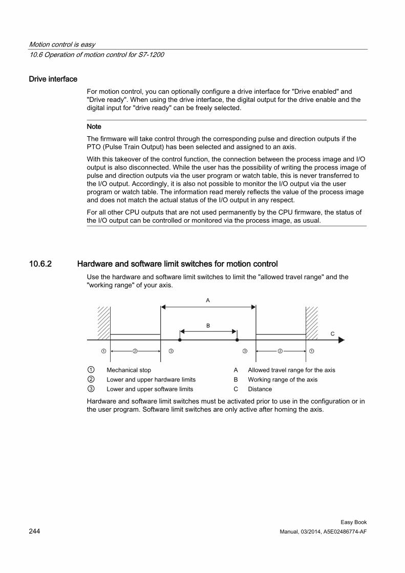
Motion control is easy 10.6 Operation of motion control for S7-1200
Easy Book 244 Manual, 03/2014, A5E02486774-AF
Drive interface For motion control, you can optionally configure a drive interface for "Drive enabled" and "Drive ready". When using the drive interface, the digital output for the drive enable and the digital input for "drive ready" can be freely selected.
Note
The firmware will take control through the corresponding pulse and direction outputs if the PTO (Pulse Train Output) has been selected and assigned to an axis.
With this takeover of the control function, the connection between the process image and I/O output is also disconnected. While the user has the possibility of writing the process image of pulse and direction outputs via the user program or watch table, this is never transferred to the I/O output. Accordingly, it is also not possible to monitor the I/O output via the user program or watch table. The information read merely reflects the value of the process image and does not match the actual status of the I/O output in any respect.
For all other CPU outputs that are not used permanently by the CPU firmware, the status of the I/O output can be controlled or monitored via the process image, as usual.
10.6.2 Hardware and software limit switches for motion control Use the hardware and software limit switches to limit the "allowed travel range" and the "working range" of your axis.
① Mechanical stop A Allowed travel range for the axis ② Lower and upper hardware limits B Working range of the axis ③ Lower and upper software limits C Distance
Hardware and software limit switches must be activated prior to use in the configuration or in the user program. Software limit switches are only active after homing the axis.
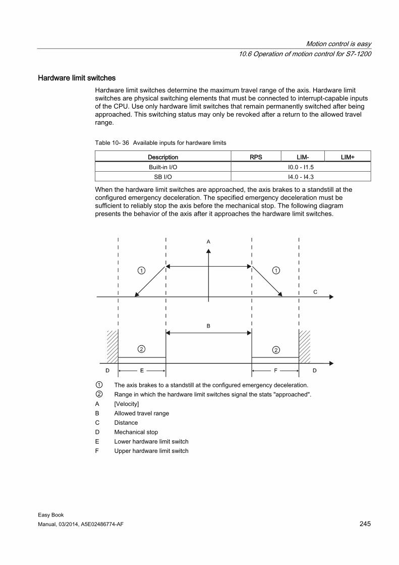
Motion control is easy 10.6 Operation of motion control for S7-1200
Easy Book Manual, 03/2014, A5E02486774-AF 245
Hardware limit switches Hardware limit switches determine the maximum travel range of the axis. Hardware limit switches are physical switching elements that must be connected to interrupt-capable inputs of the CPU. Use only hardware limit switches that remain permanently switched after being approached. This switching status may only be revoked after a return to the allowed travel range.
Table 10- 36 Available inputs for hardware limits
Description RPS LIM- LIM+ Built-in I/O I0.0 - I1.5
SB I/O I4.0 - I4.3
When the hardware limit switches are approached, the axis brakes to a standstill at the configured emergency deceleration. The specified emergency deceleration must be sufficient to reliably stop the axis before the mechanical stop. The following diagram presents the behavior of the axis after it approaches the hardware limit switches.
① The axis brakes to a standstill at the configured emergency deceleration. ② Range in which the hardware limit switches signal the stats "approached". A [Velocity] B Allowed travel range C Distance D Mechanical stop E Lower hardware limit switch F Upper hardware limit switch
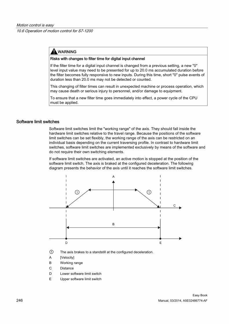
Motion control is easy 10.6 Operation of motion control for S7-1200
Easy Book 246 Manual, 03/2014, A5E02486774-AF
WARNING
Risks with changes to filter time for digital input channel
If the filter time for a digital input channel is changed from a previous setting, a new "0" level input value may need to be presented for up to 20.0 ms accumulated duration before the filter becomes fully responsive to new inputs. During this time, short "0" pulse events of duration less than 20.0 ms may not be detected or counted.
This changing of filter times can result in unexpected machine or process operation, which may cause death or serious injury to personnel, and/or damage to equipment.
To ensure that a new filter time goes immediately into effect, a power cycle of the CPU must be applied.
Software limit switches Software limit switches limit the "working range" of the axis. They should fall inside the hardware limit switches relative to the travel range. Because the positions of the software limit switches can be set flexibly, the working range of the axis can be restricted on an individual basis depending on the current traversing profile. In contrast to hardware limit switches, software limit switches are implemented exclusively by means of the software and do not require their own switching elements.
If software limit switches are activated, an active motion is stopped at the position of the software limit switch. The axis is braked at the configured deceleration. The following diagram presents the behavior of the axis until it reaches the software limit switches.
① The axis brakes to a standstill at the configured deceleration. A [Velocity] B Working range C Distance D Lower software limit switch E Upper software limit switch
Motion control is easy 10.6 Operation of motion control for S7-1200
Easy Book Manual, 03/2014, A5E02486774-AF 247
Use additional hardware limit switches if a mechanical endstop is located after the software limit switches and there is a risk of mechanical damage.
Additional information Your user program can override the hardware or software position limits by enabling or disabling both hardware and software limits functionality. The selection is made from the Axis DB.
● To enable or disable the hardware limit functionality, access the "Active" tag (Bool) in the DB path "<axis name>/Config/PositonLimits_HW". The state of the "Active" tag enables or disables the use of hardware position limits.
● To enable or disable software position limit functionality, access "Active" tag (Bool) in the DB path "<axis name>/Config/Position Limits_SW". The state of this "Active" tag enables or disables the software position limits.
You can also modify the software position limits with your user program (for example, to add flexibility for machine setup or to shorten machine change-over time). Your user program can write new values to the " MinPosition " and " MaxPosition " tags (engineering units in Real format) in the DB "<axis name>/Config/PositionLimits_SW".
10.6.3 Homing
10.6.3.1 Homing the axis Homing refers to the matching of the axis coordinates to the real, physical drive position. (If the drive is currently at position x, the axis will be adjusted to be in position x.) For position-controlled axes, the entries and displays for the position refer exactly to these axis coordinates.
Note
The agreement between the axis coordinates and the real situation is extremely important. This step is necessary to ensure that the absolute target position of the axis is also achieved exactly with the drive.
The MC_Home instruction initiates the homing of the axis.
Motion control is easy 10.6 Operation of motion control for S7-1200
Easy Book 248 Manual, 03/2014, A5E02486774-AF
There are 4 different homing functions. The first two functions allow the user to set the current position of the axis and the second two position the axis with respect to a Home reference Sensor.
● Mode 0 - Direct Referencing Absolute: When executed this mode tells the axis exactly where it is. It sets the internal position variable to the value of the Position input of the Homing instruction. This is used for machine calibration and setup.
The axis position is set regardless of the reference point switch. Active traversing motions are not aborted. The value of the Position input parameter of the MC_Home instruction is set immediately as the reference point of the axis. To assign the reference point to an exact mechanical position, the axis must be at a standstill at this position at the time of the homing operation.
● Mode 1 - Direct Referencing Relative: When executed this mode uses the internal position variable and adds the value of the Position input on the Homing instruction to it. This is typically used to account for machine offset.
The axis position is set regardless of the reference point switch. Active traversing motions are not aborted. The following statement applies to the axis position after homing: New axis position = current axis position + value of the Position parameter of the MC_Home instruction.
● Mode 2 - Passive Referencing: When the axis is moving and passes the Reference Point Switch the current position is set as the home position. This feature will help account for normal machine wear and gear backlash and prevent the need for manual compensation for wear. The Position input on the Homing instruction, as before, adds to the location indicated by the Reference Point Switch allowing easy offset of the Home position.
During passive homing, the MC_Home instruction does not carry out any homing motion. The traversing motion required for this step must be implemented by the user via other motion control instructions. When the reference point switch is detected, the axis is homed according to the configuration. Active traversing motions are not aborted upon start of passive homing.
● Mode 3 - Active Referencing: This mode is the most precise method of Homing the Axis. The initial direction and velocity of movement is configured in the Technology Object Configuration Extended Parameters-Homing. This is dependent upon machine configuration. There is also the ability to determine if the leading edge or falling edge of the Reference Point Switch signal is the Home position. Virtually all sensors have an active range and if the Steady State On position was used as the Home signal then there would be a possibility for error in the Homing position since the On signal active range would cover a range of distance. By using either the leading or falling edge of that signal a much more precise Home position results. As with all other modes the value of the Position input on the Homing instruction is added to the Hardware referenced position.
In active homing mode, the MC_Home instruction performs the required reference point approach. When the reference point switch is detected, the axis is homed according to the configuration. Active traversing motions are aborted.
Modes 0 and 1 do not require that the axis be moved at all. They are typically used in setup and calibration. Modes 2 and 3 require that the axis move and pass a sensor that is configured in the "Axis" technology object as the Reference Point Switch. The reference point can be placed in the work area of the axis or outside of the normal work area but within movement range.
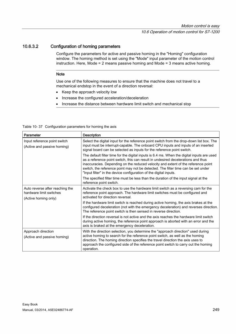
Motion control is easy 10.6 Operation of motion control for S7-1200
Easy Book Manual, 03/2014, A5E02486774-AF 249
10.6.3.2 Configuration of homing parameters Configure the parameters for active and passive homing in the "Homing" configuration window. The homing method is set using the "Mode" input parameter of the motion control instruction. Here, Mode = 2 means passive homing and Mode = 3 means active homing.
Note
Use one of the following measures to ensure that the machine does not travel to a mechanical endstop in the event of a direction reversal: • Keep the approach velocity low • Increase the configured acceleration/deceleration • Increase the distance between hardware limit switch and mechanical stop
Table 10- 37 Configuration parameters for homing the axis
Parameter Description Input reference point switch (Active and passive homing)
Select the digital input for the reference point switch from the drop-down list box. The input must be interrupt-capable. The onboard CPU inputs and inputs of an inserted signal board can be selected as inputs for the reference point switch. The default filter time for the digital inputs is 6.4 ms. When the digital inputs are used as a reference point switch, this can result in undesired decelerations and thus inaccuracies. Depending on the reduced velocity and extent of the reference point switch, the reference point may not be detected. The filter time can be set under "Input filter" in the device configuration of the digital inputs. The specified filter time must be less than the duration of the input signal at the reference point switch.
Auto reverse after reaching the hardware limit switches (Active homing only)
Activate the check box to use the hardware limit switch as a reversing cam for the reference point approach. The hardware limit switches must be configured and activated for direction reversal. If the hardware limit switch is reached during active homing, the axis brakes at the configured deceleration (not with the emergency deceleration) and reverses direction. The reference point switch is then sensed in reverse direction. If the direction reversal is not active and the axis reaches the hardware limit switch during active homing, the reference point approach is aborted with an error and the axis is braked at the emergency deceleration.
Approach direction (Active and passive homing)
With the direction selection, you determine the "approach direction" used during active homing to search for the reference point switch, as well as the homing direction. The homing direction specifies the travel direction the axis uses to approach the configured side of the reference point switch to carry out the homing operation.
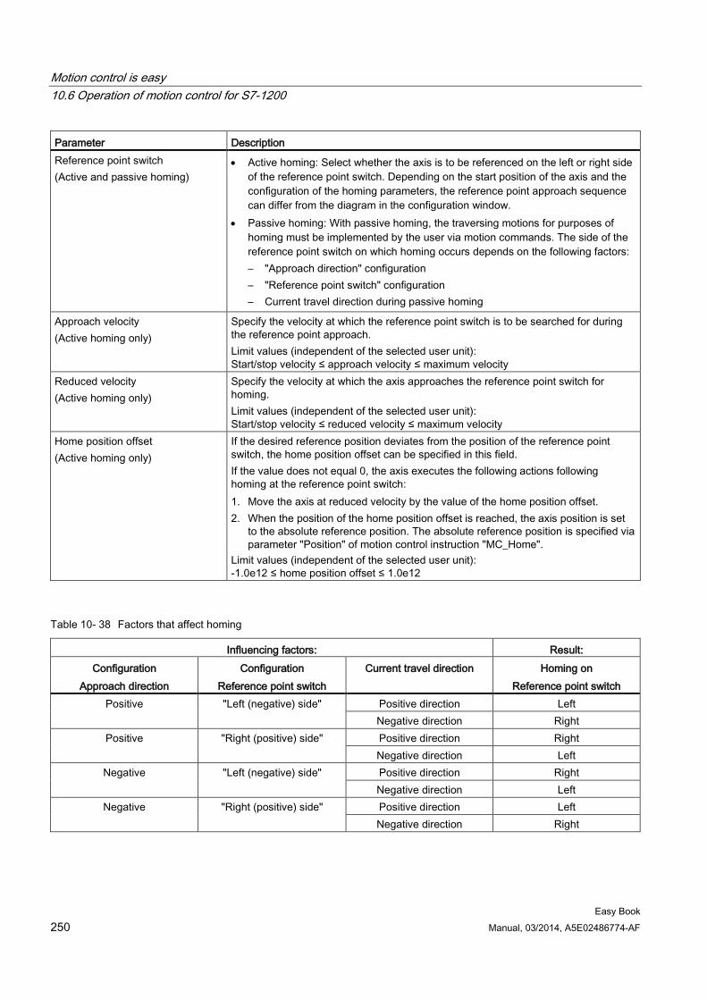
Motion control is easy 10.6 Operation of motion control for S7-1200
Easy Book 250 Manual, 03/2014, A5E02486774-AF
Parameter Description Reference point switch (Active and passive homing)
• Active homing: Select whether the axis is to be referenced on the left or right side of the reference point switch. Depending on the start position of the axis and the configuration of the homing parameters, the reference point approach sequence can differ from the diagram in the configuration window.
• Passive homing: With passive homing, the traversing motions for purposes of homing must be implemented by the user via motion commands. The side of the reference point switch on which homing occurs depends on the following factors: – "Approach direction" configuration – "Reference point switch" configuration – Current travel direction during passive homing
Approach velocity (Active homing only)
Specify the velocity at which the reference point switch is to be searched for during the reference point approach. Limit values (independent of the selected user unit): Start/stop velocity ≤ approach velocity ≤ maximum velocity
Reduced velocity (Active homing only)
Specify the velocity at which the axis approaches the reference point switch for homing. Limit values (independent of the selected user unit): Start/stop velocity ≤ reduced velocity ≤ maximum velocity
Home position offset (Active homing only)
If the desired reference position deviates from the position of the reference point switch, the home position offset can be specified in this field. If the value does not equal 0, the axis executes the following actions following homing at the reference point switch: 1. Move the axis at reduced velocity by the value of the home position offset. 2. When the position of the home position offset is reached, the axis position is set
to the absolute reference position. The absolute reference position is specified via parameter "Position" of motion control instruction "MC_Home".
Limit values (independent of the selected user unit): -1.0e12 ≤ home position offset ≤ 1.0e12
Table 10- 38 Factors that affect homing
Influencing factors: Result: Configuration
Approach direction Configuration
Reference point switch Current travel direction Homing on
Reference point switch Positive "Left (negative) side" Positive direction Left
Negative direction Right Positive "Right (positive) side" Positive direction Right
Negative direction Left Negative "Left (negative) side" Positive direction Right
Negative direction Left Negative "Right (positive) side" Positive direction Left
Negative direction Right
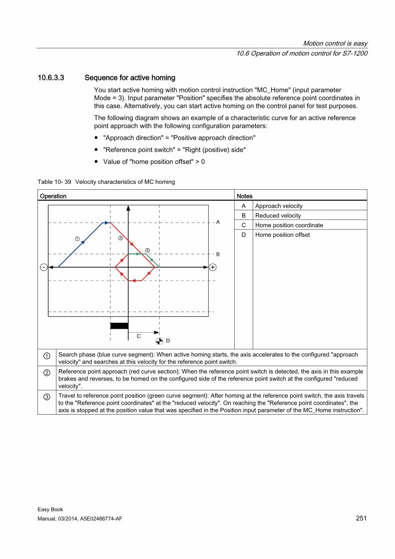
Motion control is easy 10.6 Operation of motion control for S7-1200
Easy Book Manual, 03/2014, A5E02486774-AF 251
10.6.3.3 Sequence for active homing You start active homing with motion control instruction "MC_Home" (input parameter Mode = 3). Input parameter "Position" specifies the absolute reference point coordinates in this case. Alternatively, you can start active homing on the control panel for test purposes.
The following diagram shows an example of a characteristic curve for an active reference point approach with the following configuration parameters:
● "Approach direction" = "Positive approach direction"
● "Reference point switch" = "Right (positive) side"
● Value of "home position offset" > 0
Table 10- 39 Velocity characteristics of MC homing
Operation Notes
A Approach velocity B Reduced velocity C Home position coordinate D Home position offset
① Search phase (blue curve segment): When active homing starts, the axis accelerates to the configured "approach velocity" and searches at this velocity for the reference point switch.
② Reference point approach (red curve section): When the reference point switch is detected, the axis in this example brakes and reverses, to be homed on the configured side of the reference point switch at the configured "reduced velocity".
③ Travel to reference point position (green curve segment): After homing at the reference point switch, the axis travels to the "Reference point coordinates" at the "reduced velocity". On reaching the "Reference point coordinates", the axis is stopped at the position value that was specified in the Position input parameter of the MC_Home instruction".
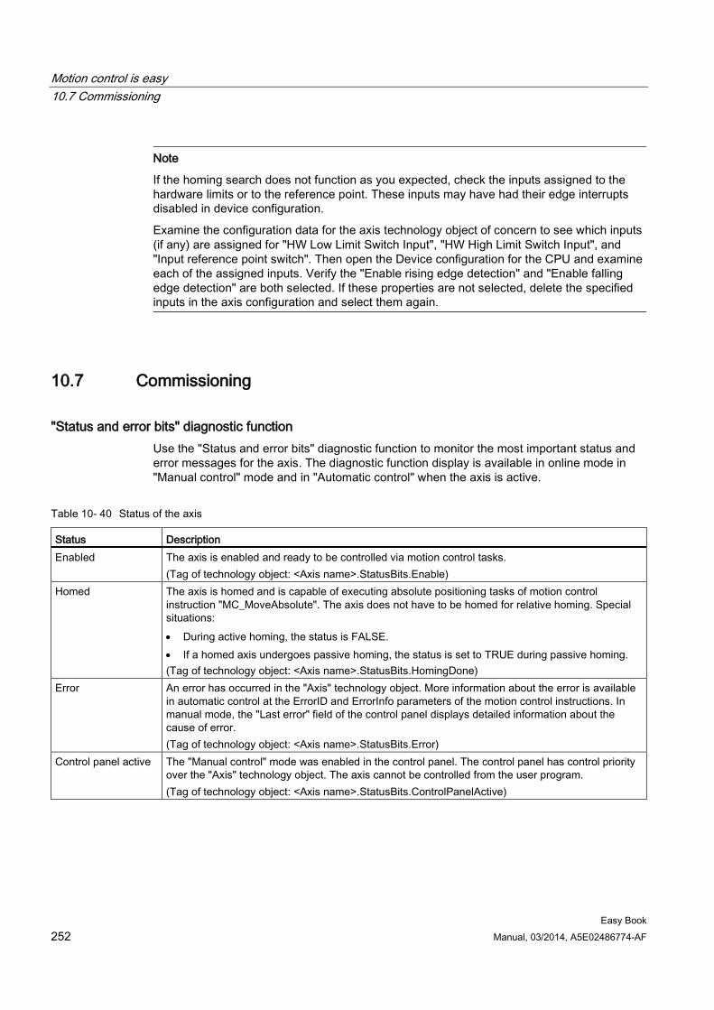
Motion control is easy 10.7 Commissioning
Easy Book 252 Manual, 03/2014, A5E02486774-AF
Note
If the homing search does not function as you expected, check the inputs assigned to the hardware limits or to the reference point. These inputs may have had their edge interrupts disabled in device configuration.
Examine the configuration data for the axis technology object of concern to see which inputs (if any) are assigned for "HW Low Limit Switch Input", "HW High Limit Switch Input", and "Input reference point switch". Then open the Device configuration for the CPU and examine each of the assigned inputs. Verify the "Enable rising edge detection" and "Enable falling edge detection" are both selected. If these properties are not selected, delete the specified inputs in the axis configuration and select them again.
10.7 Commissioning
"Status and error bits" diagnostic function Use the "Status and error bits" diagnostic function to monitor the most important status and error messages for the axis. The diagnostic function display is available in online mode in "Manual control" mode and in "Automatic control" when the axis is active.
Table 10- 40 Status of the axis
Status Description Enabled The axis is enabled and ready to be controlled via motion control tasks.
(Tag of technology object: <Axis name>.StatusBits.Enable) Homed The axis is homed and is capable of executing absolute positioning tasks of motion control
instruction "MC_MoveAbsolute". The axis does not have to be homed for relative homing. Special situations: • During active homing, the status is FALSE. • If a homed axis undergoes passive homing, the status is set to TRUE during passive homing. (Tag of technology object: <Axis name>.StatusBits.HomingDone)
Error An error has occurred in the "Axis" technology object. More information about the error is available in automatic control at the ErrorID and ErrorInfo parameters of the motion control instructions. In manual mode, the "Last error" field of the control panel displays detailed information about the cause of error. (Tag of technology object: <Axis name>.StatusBits.Error)
Control panel active The "Manual control" mode was enabled in the control panel. The control panel has control priority over the "Axis" technology object. The axis cannot be controlled from the user program. (Tag of technology object: <Axis name>.StatusBits.ControlPanelActive)
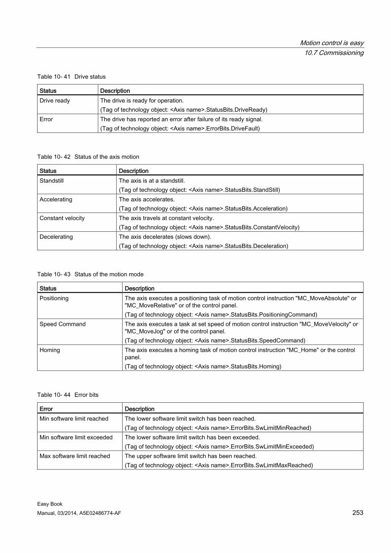
Motion control is easy 10.7 Commissioning
Easy Book Manual, 03/2014, A5E02486774-AF 253
Table 10- 41 Drive status
Status Description Drive ready The drive is ready for operation.
(Tag of technology object: <Axis name>.StatusBits.DriveReady) Error The drive has reported an error after failure of its ready signal.
(Tag of technology object: <Axis name>.ErrorBits.DriveFault)
Table 10- 42 Status of the axis motion
Status Description Standstill The axis is at a standstill.
(Tag of technology object: <Axis name>.StatusBits.StandStill) Accelerating The axis accelerates.
(Tag of technology object: <Axis name>.StatusBits.Acceleration) Constant velocity The axis travels at constant velocity.
(Tag of technology object: <Axis name>.StatusBits.ConstantVelocity) Decelerating The axis decelerates (slows down).
(Tag of technology object: <Axis name>.StatusBits.Deceleration)
Table 10- 43 Status of the motion mode
Status Description Positioning The axis executes a positioning task of motion control instruction "MC_MoveAbsolute" or
"MC_MoveRelative" or of the control panel. (Tag of technology object: <Axis name>.StatusBits.PositioningCommand)
Speed Command The axis executes a task at set speed of motion control instruction "MC_MoveVelocity" or "MC_MoveJog" or of the control panel. (Tag of technology object: <Axis name>.StatusBits.SpeedCommand)
Homing The axis executes a homing task of motion control instruction "MC_Home" or the control panel. (Tag of technology object: <Axis name>.StatusBits.Homing)
Table 10- 44 Error bits
Error Description Min software limit reached The lower software limit switch has been reached.
(Tag of technology object: <Axis name>.ErrorBits.SwLimitMinReached) Min software limit exceeded The lower software limit switch has been exceeded.
(Tag of technology object: <Axis name>.ErrorBits.SwLimitMinExceeded) Max software limit reached The upper software limit switch has been reached.
(Tag of technology object: <Axis name>.ErrorBits.SwLimitMaxReached)
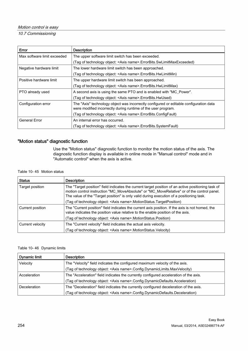
Motion control is easy 10.7 Commissioning
Easy Book 254 Manual, 03/2014, A5E02486774-AF
Error Description Max software limit exceeded The upper software limit switch has been exceeded.
(Tag of technology object: <Axis name>.ErrorBits.SwLimitMaxExceeded) Negative hardware limit The lower hardware limit switch has been approached.
(Tag of technology object: <Axis name>.ErrorBits.HwLimitMin) Positive hardware limit The upper hardware limit switch has been approached.
(Tag of technology object: <Axis name>.ErrorBits.HwLimitMax) PTO already used A second axis is using the same PTO and is enabled with "MC_Power".
(Tag of technology object: <Axis name>.ErrorBits.HwUsed) Configuration error The "Axis" technology object was incorrectly configured or editable configuration data
were modified incorrectly during runtime of the user program. (Tag of technology object: <Axis name>.ErrorBits.ConfigFault)
General Error An internal error has occurred. (Tag of technology object: <Axis name>.ErrorBits.SystemFault)
"Motion status" diagnostic function Use the "Motion status" diagnostic function to monitor the motion status of the axis. The diagnostic function display is available in online mode in "Manual control" mode and in "Automatic control" when the axis is active.
Table 10- 45 Motion status
Status Description Target position The "Target position" field indicates the current target position of an active positioning task of
motion control instruction "MC_MoveAbsolute" or "MC_MoveRelative" or of the control panel. The value of the "Target position" is only valid during execution of a positioning task. (Tag of technology object: <Axis name>.MotionStatus.TargetPosition)
Current position The "Current position" field indicates the current axis position. If the axis is not homed, the value indicates the position value relative to the enable position of the axis. (Tag of technology object: <Axis name>.MotionStatus.Position)
Current velocity The "Current velocity" field indicates the actual axis velocity. (Tag of technology object: <Axis name>.MotionStatus.Velocity)
Table 10- 46 Dynamic limits
Dynamic limit Description Velocity The "Velocity" field indicates the configured maximum velocity of the axis.
(Tag of technology object: <Axis name>.Config.DynamicLimits.MaxVelocity) Acceleration The "Acceleration" field indicates the currently configured acceleration of the axis.
(Tag of technology object: <Axis name>.Config.DynamicDefaults.Acceleration) Deceleration The "Deceleration" field indicates the currently configured deceleration of the axis.
(Tag of technology object: <Axis name>.Config.DynamicDefaults.Deceleration)
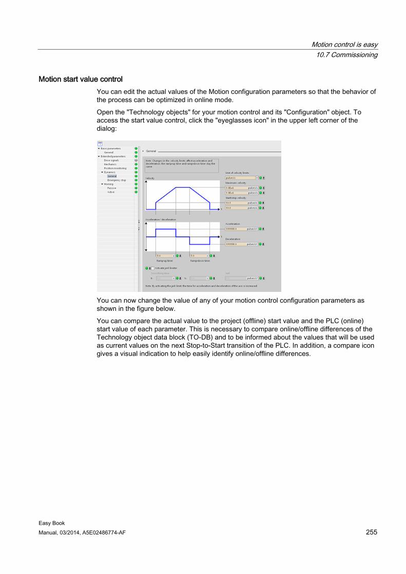
Motion control is easy 10.7 Commissioning
Easy Book Manual, 03/2014, A5E02486774-AF 255
Motion start value control You can edit the actual values of the Motion configuration parameters so that the behavior of the process can be optimized in online mode.
Open the "Technology objects" for your motion control and its "Configuration" object. To access the start value control, click the "eyeglasses icon" in the upper left corner of the dialog:
You can now change the value of any of your motion control configuration parameters as shown in the figure below.
You can compare the actual value to the project (offline) start value and the PLC (online) start value of each parameter. This is necessary to compare online/offline differences of the Technology object data block (TO-DB) and to be informed about the values that will be used as current values on the next Stop-to-Start transition of the PLC. In addition, a compare icon gives a visual indication to help easily identify online/offline differences.
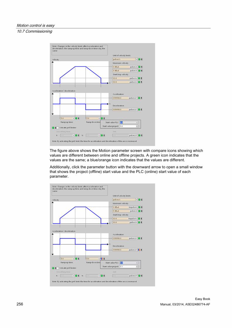
Motion control is easy 10.7 Commissioning
Easy Book 256 Manual, 03/2014, A5E02486774-AF
The figure above shows the Motion parameter screen with compare icons showing which values are different between online and offline projects. A green icon indicates that the values are the same; a blue/orange icon indicates that the values are different.
Additionally, click the parameter button with the downward arrow to open a small window that shows the project (offline) start value and the PLC (online) start value of each parameter.
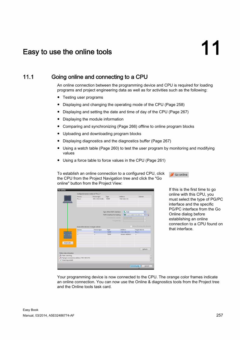
Easy Book Manual, 03/2014, A5E02486774-AF 257
Easy to use the online tools 11 11.1 Going online and connecting to a CPU
An online connection between the programming device and CPU is required for loading programs and project engineering data as well as for activities such as the following:
● Testing user programs
● Displaying and changing the operating mode of the CPU (Page 258)
● Displaying and setting the date and time of day of the CPU (Page 267)
● Displaying the module information
● Comparing and synchronizing (Page 266) offline to online program blocks
● Uploading and downloading program blocks
● Displaying diagnostics and the diagnostics buffer (Page 267)
● Using a watch table (Page 260) to test the user program by monitoring and modifying values
● Using a force table to force values in the CPU (Page 261)
To establish an online connection to a configured CPU, click the CPU from the Project Navigation tree and click the "Go online" button from the Project View:
If this is the first time to go online with this CPU, you must select the type of PG/PC interface and the specific PG/PC interface from the Go Online dialog before establishing an online connection to a CPU found on that interface.
Your programming device is now connected to the CPU. The orange color frames indicate an online connection. You can now use the Online & diagnostics tools from the Project tree and the Online tools task card.
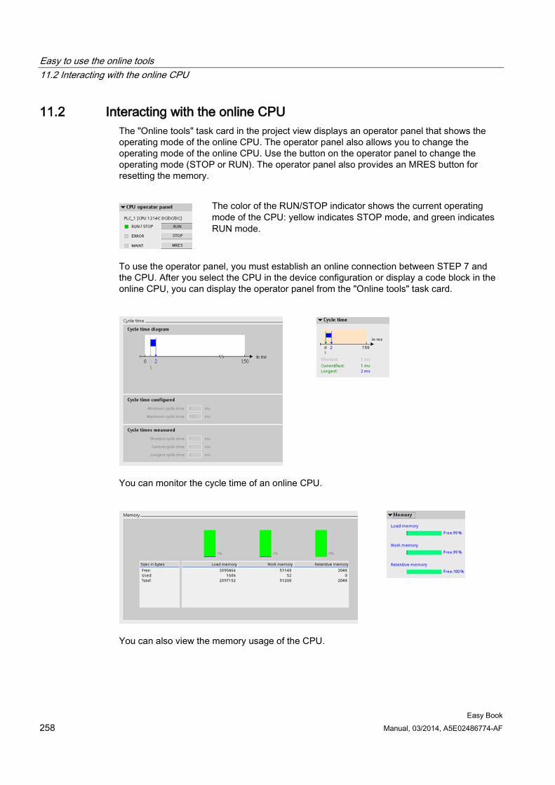
Easy to use the online tools 11.2 Interacting with the online CPU
Easy Book 258 Manual, 03/2014, A5E02486774-AF
11.2 Interacting with the online CPU The "Online tools" task card in the project view displays an operator panel that shows the operating mode of the online CPU. The operator panel also allows you to change the operating mode of the online CPU. Use the button on the operator panel to change the operating mode (STOP or RUN). The operator panel also provides an MRES button for resetting the memory.
The color of the RUN/STOP indicator shows the current operating mode of the CPU: yellow indicates STOP mode, and green indicates RUN mode.
To use the operator panel, you must establish an online connection between STEP 7 and the CPU. After you select the CPU in the device configuration or display a code block in the online CPU, you can display the operator panel from the "Online tools" task card.
You can monitor the cycle time of an online CPU.
You can also view the memory usage of the CPU.
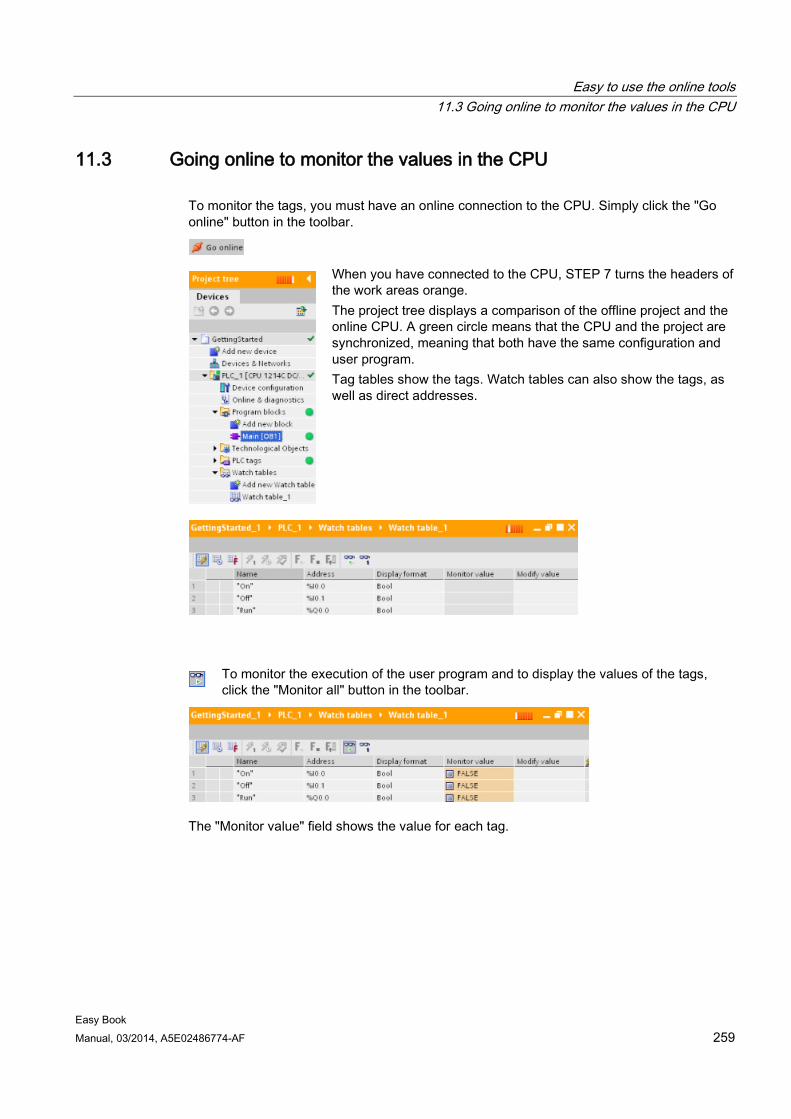
Easy to use the online tools 11.3 Going online to monitor the values in the CPU
Easy Book Manual, 03/2014, A5E02486774-AF 259
11.3 Going online to monitor the values in the CPU To monitor the tags, you must have an online connection to the CPU. Simply click the "Go online" button in the toolbar.
When you have connected to the CPU, STEP 7 turns the headers of the work areas orange. The project tree displays a comparison of the offline project and the online CPU. A green circle means that the CPU and the project are synchronized, meaning that both have the same configuration and user program. Tag tables show the tags. Watch tables can also show the tags, as well as direct addresses.
To monitor the execution of the user program and to display the values of the tags, click the "Monitor all" button in the toolbar.
The "Monitor value" field shows the value for each tag.
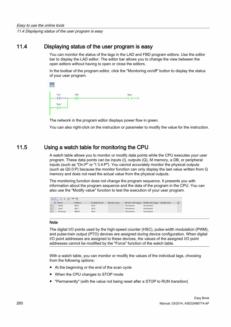
Easy to use the online tools 11.4 Displaying status of the user program is easy
Easy Book 260 Manual, 03/2014, A5E02486774-AF
11.4 Displaying status of the user program is easy You can monitor the status of the tags in the LAD and FBD program editors. Use the editor bar to display the LAD editor. The editor bar allows you to change the view between the open editors without having to open or close the editors.
In the toolbar of the program editor, click the "Monitoring on/off" button to display the status of your user program.
The network in the program editor displays power flow in green.
You can also right-click on the instruction or parameter to modify the value for the instruction.
11.5 Using a watch table for monitoring the CPU A watch table allows you to monitor or modify data points while the CPU executes your user program. These data points can be inputs (I), outputs (Q), M memory, a DB, or peripheral inputs (such as "On:P" or "I 3.4:P"). You cannot accurately monitor the physical outputs (such as Q0.0:P) because the monitor function can only display the last value written from Q memory and does not read the actual value from the physical outputs.
The monitoring function does not change the program sequence. It presents you with information about the program sequence and the data of the program in the CPU. You can also use the "Modify value" function to test the execution of your user program.
Note
The digital I/O points used by the high-speed counter (HSC), pulse-width modulation (PWM), and pulse-train output (PTO) devices are assigned during device configuration. When digital I/O point addresses are assigned to these devices, the values of the assigned I/O point addresses cannot be modified by the "Force" function of the watch table.
With a watch table, you can monitor or modify the values of the individual tags, choosing from the following options:
● At the beginning or the end of the scan cycle
● When the CPU changes to STOP mode
● "Permanently" (with the value not being reset after a STOP to RUN transition)
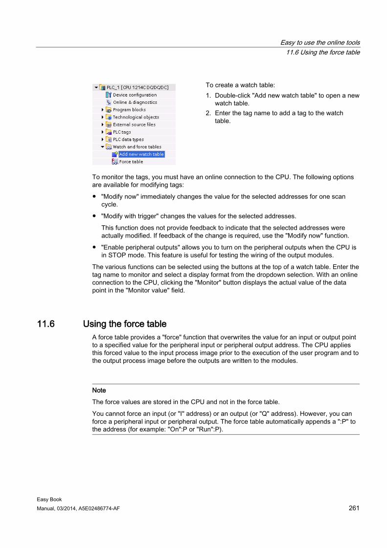
Easy to use the online tools 11.6 Using the force table
Easy Book Manual, 03/2014, A5E02486774-AF 261
To create a watch table: 1. Double-click "Add new watch table" to open a new
watch table. 2. Enter the tag name to add a tag to the watch
table.
To monitor the tags, you must have an online connection to the CPU. The following options are available for modifying tags:
● "Modify now" immediately changes the value for the selected addresses for one scan cycle.
● "Modify with trigger" changes the values for the selected addresses.
This function does not provide feedback to indicate that the selected addresses were actually modified. If feedback of the change is required, use the "Modify now" function.
● "Enable peripheral outputs" allows you to turn on the peripheral outputs when the CPU is in STOP mode. This feature is useful for testing the wiring of the output modules.
The various functions can be selected using the buttons at the top of a watch table. Enter the tag name to monitor and select a display format from the dropdown selection. With an online connection to the CPU, clicking the "Monitor" button displays the actual value of the data point in the "Monitor value" field.
11.6 Using the force table A force table provides a "force" function that overwrites the value for an input or output point to a specified value for the peripheral input or peripheral output address. The CPU applies this forced value to the input process image prior to the execution of the user program and to the output process image before the outputs are written to the modules.
Note
The force values are stored in the CPU and not in the force table.
You cannot force an input (or "I" address) or an output (or "Q" address). However, you can force a peripheral input or peripheral output. The force table automatically appends a ":P" to the address (for example: "On":P or "Run":P).
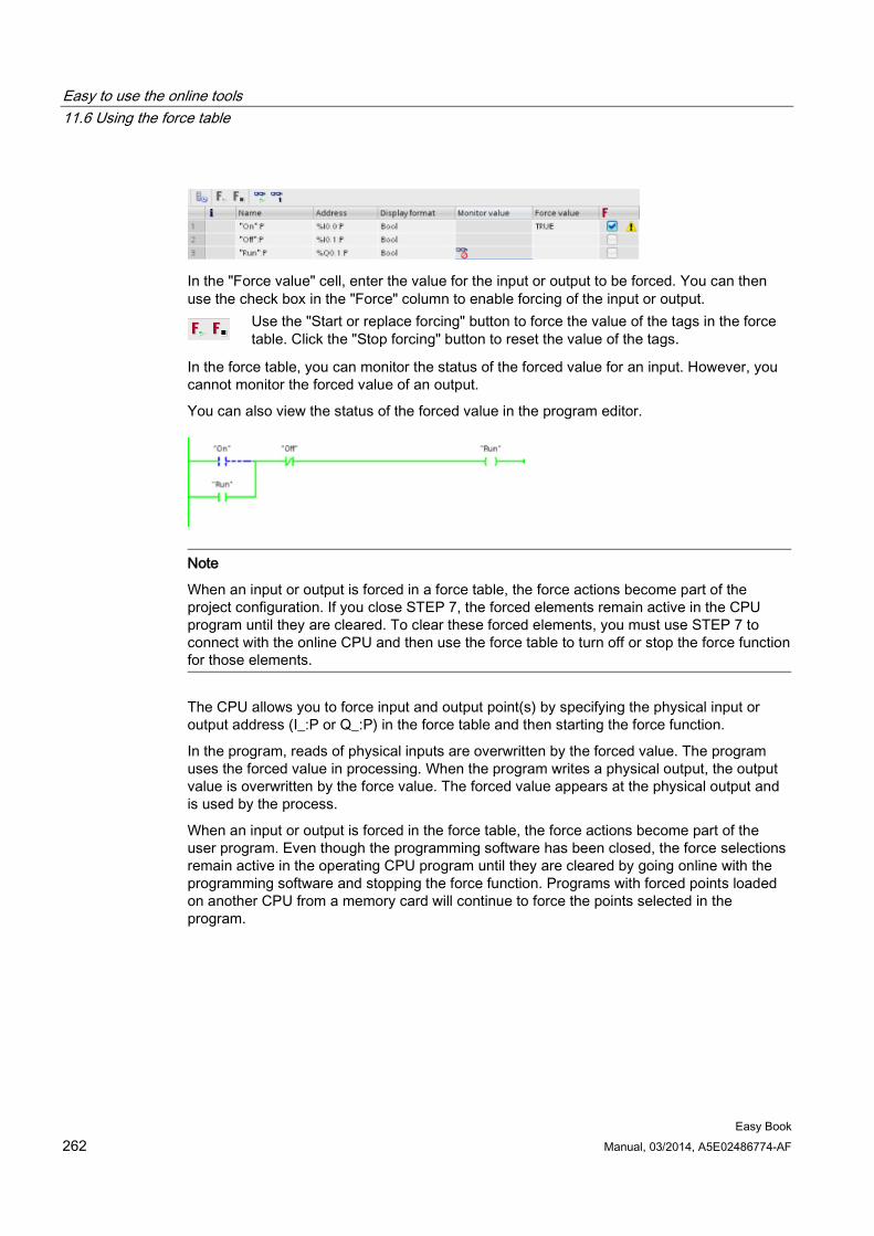
Easy to use the online tools 11.6 Using the force table
Easy Book 262 Manual, 03/2014, A5E02486774-AF
In the "Force value" cell, enter the value for the input or output to be forced. You can then use the check box in the "Force" column to enable forcing of the input or output.
Use the "Start or replace forcing" button to force the value of the tags in the force table. Click the "Stop forcing" button to reset the value of the tags.
In the force table, you can monitor the status of the forced value for an input. However, you cannot monitor the forced value of an output.
You can also view the status of the forced value in the program editor.
Note
When an input or output is forced in a force table, the force actions become part of the project configuration. If you close STEP 7, the forced elements remain active in the CPU program until they are cleared. To clear these forced elements, you must use STEP 7 to connect with the online CPU and then use the force table to turn off or stop the force function for those elements.
The CPU allows you to force input and output point(s) by specifying the physical input or output address (I_:P or Q_:P) in the force table and then starting the force function.
In the program, reads of physical inputs are overwritten by the forced value. The program uses the forced value in processing. When the program writes a physical output, the output value is overwritten by the force value. The forced value appears at the physical output and is used by the process.
When an input or output is forced in the force table, the force actions become part of the user program. Even though the programming software has been closed, the force selections remain active in the operating CPU program until they are cleared by going online with the programming software and stopping the force function. Programs with forced points loaded on another CPU from a memory card will continue to force the points selected in the program.
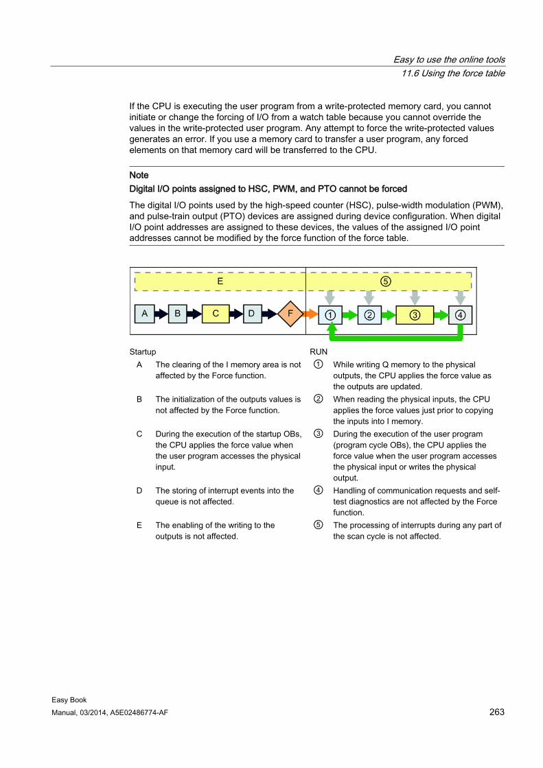
Easy to use the online tools 11.6 Using the force table
Easy Book Manual, 03/2014, A5E02486774-AF 263
If the CPU is executing the user program from a write-protected memory card, you cannot initiate or change the forcing of I/O from a watch table because you cannot override the values in the write-protected user program. Any attempt to force the write-protected values generates an error. If you use a memory card to transfer a user program, any forced elements on that memory card will be transferred to the CPU.
Note Digital I/O points assigned to HSC, PWM, and PTO cannot be forced
The digital I/O points used by the high-speed counter (HSC), pulse-width modulation (PWM), and pulse-train output (PTO) devices are assigned during device configuration. When digital I/O point addresses are assigned to these devices, the values of the assigned I/O point addresses cannot be modified by the force function of the force table.
Startup RUN
A The clearing of the I memory area is not affected by the Force function.
① While writing Q memory to the physical outputs, the CPU applies the force value as the outputs are updated.
B The initialization of the outputs values is not affected by the Force function.
② When reading the physical inputs, the CPU applies the force values just prior to copying the inputs into I memory.
C During the execution of the startup OBs, the CPU applies the force value when the user program accesses the physical input.
③ During the execution of the user program (program cycle OBs), the CPU applies the force value when the user program accesses the physical input or writes the physical output.
D The storing of interrupt events into the queue is not affected.
④ Handling of communication requests and self-test diagnostics are not affected by the Force function.
E The enabling of the writing to the outputs is not affected.
⑤ The processing of interrupts during any part of the scan cycle is not affected.
Easy to use the online tools 11.7 Capturing the online values of a DB to reset the start values
Easy Book 264 Manual, 03/2014, A5E02486774-AF
11.7 Capturing the online values of a DB to reset the start values You can capture the current values being monitored in an online CPU to become the start values for a global DB.
● You must have an online connection to the CPU.
● The CPU must be in RUN mode.
● You must have opened the DB in STEP 7.
Use the "Show a snapshot of the monitored values" button to capture the current values of the selected tags in the DB. You can then copy these values into the "Start value" column of the DB.
1. In the DB editor, click the "Monitor all tags" button. The "Monitor value" column displays the current data values.
2. Click the "Show a snapshot of the monitored values" button to display the current values in the "Snapshot" column.
3. Click the "Monitor all" button to stop monitoring the data in the CPU.
4. Copy a value in the "Snapshot" column for a tag.
– Select a value to be copied.
– Right-click the selected value to display the context menu.
– Select the "Copy" command.
5. Paste the copied value into the corresponding "Start value" column for the tag. (Right-click the cell and select "Paste" from the context menu.)
6. Save the project to configure the copied values as the new start values for the DB.
7. Compile and download the DB to the CPU. The DB uses the new start values after the CPU goes to RUN mode.
Note
The values that are shown in the "Monitor value" column are always copied from the CPU. STEP 7 does not check whether all values come from the same scan cycle of the CPU.
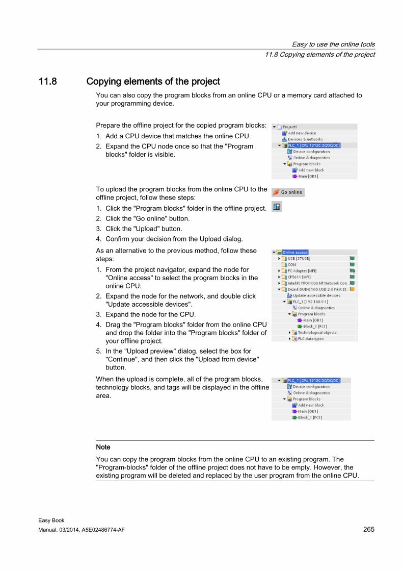
Easy to use the online tools 11.8 Copying elements of the project
Easy Book Manual, 03/2014, A5E02486774-AF 265
11.8 Copying elements of the project You can also copy the program blocks from an online CPU or a memory card attached to your programming device.
Prepare the offline project for the copied program blocks: 1. Add a CPU device that matches the online CPU. 2. Expand the CPU node once so that the "Program
blocks" folder is visible.
To upload the program blocks from the online CPU to the offline project, follow these steps: 1. Click the "Program blocks" folder in the offline project. 2. Click the "Go online" button. 3. Click the "Upload" button. 4. Confirm your decision from the Upload dialog.
As an alternative to the previous method, follow these steps: 1. From the project navigator, expand the node for
"Online access" to select the program blocks in the online CPU:
2. Expand the node for the network, and double click "Update accessible devices".
3. Expand the node for the CPU. 4. Drag the "Program blocks" folder from the online CPU
and drop the folder into the "Program blocks" folder of your offline project.
5. In the "Upload preview" dialog, select the box for "Continue", and then click the "Upload from device" button.
When the upload is complete, all of the program blocks, technology blocks, and tags will be displayed in the offline area.
Note
You can copy the program blocks from the online CPU to an existing program. The "Program-blocks" folder of the offline project does not have to be empty. However, the existing program will be deleted and replaced by the user program from the online CPU.
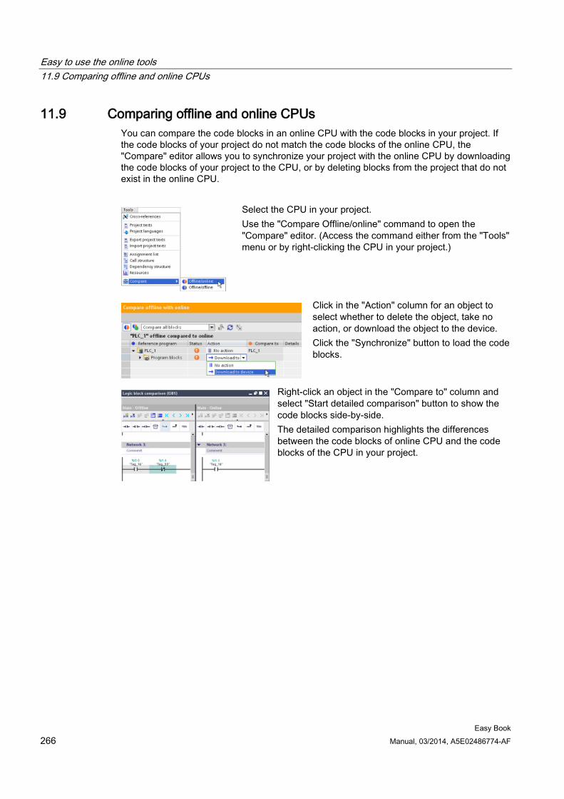
Easy to use the online tools 11.9 Comparing offline and online CPUs
Easy Book 266 Manual, 03/2014, A5E02486774-AF
11.9 Comparing offline and online CPUs You can compare the code blocks in an online CPU with the code blocks in your project. If the code blocks of your project do not match the code blocks of the online CPU, the "Compare" editor allows you to synchronize your project with the online CPU by downloading the code blocks of your project to the CPU, or by deleting blocks from the project that do not exist in the online CPU.
Select the CPU in your project. Use the "Compare Offline/online" command to open the "Compare" editor. (Access the command either from the "Tools" menu or by right-clicking the CPU in your project.)
Click in the "Action" column for an object to select whether to delete the object, take no action, or download the object to the device. Click the "Synchronize" button to load the code blocks.
Right-click an object in the "Compare to" column and select "Start detailed comparison" button to show the code blocks side-by-side. The detailed comparison highlights the differences between the code blocks of online CPU and the code blocks of the CPU in your project.
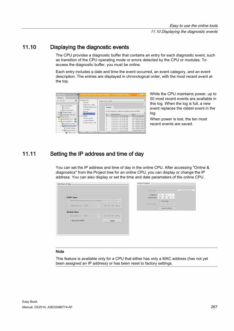
Easy to use the online tools 11.10 Displaying the diagnostic events
Easy Book Manual, 03/2014, A5E02486774-AF 267
11.10 Displaying the diagnostic events The CPU provides a diagnostic buffer that contains an entry for each diagnostic event, such as transition of the CPU operating mode or errors detected by the CPU or modules. To access the diagnostic buffer, you must be online.
Each entry includes a date and time the event occurred, an event category, and an event description. The entries are displayed in chronological order, with the most recent event at the top.
While the CPU maintains power, up to 50 most recent events are available in this log. When the log is full, a new event replaces the oldest event in the log. When power is lost, the ten most recent events are saved.
11.11 Setting the IP address and time of day You can set the IP address and time of day in the online CPU. After accessing "Online & diagnostics" from the Project tree for an online CPU, you can display or change the IP address. You can also display or set the time and date parameters of the online CPU.
Note
This feature is available only for a CPU that either has only a MAC address (has not yet been assigned an IP address) or has been reset to factory settings.
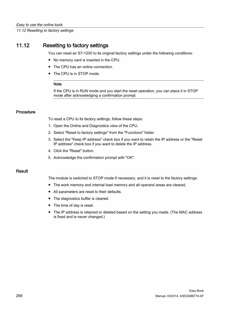
Easy to use the online tools 11.12 Resetting to factory settings
Easy Book 268 Manual, 03/2014, A5E02486774-AF
11.12 Resetting to factory settings You can reset an S7-1200 to its original factory settings under the following conditions:
● No memory card is inserted in the CPU.
● The CPU has an online connection.
● The CPU is in STOP mode.
Note
If the CPU is in RUN mode and you start the reset operation, you can place it in STOP mode after acknowledging a confirmation prompt.
Procedure To reset a CPU to its factory settings, follow these steps:
1. Open the Online and Diagnostics view of the CPU.
2. Select "Reset to factory settings" from the "Functions" folder.
3. Select the "Keep IP address" check box if you want to retain the IP address or the "Reset IP address" check box if you want to delete the IP address.
4. Click the "Reset" button.
5. Acknowledge the confirmation prompt with "OK".
Result The module is switched to STOP mode if necessary, and it is reset to the factory settings:
● The work memory and internal load memory and all operand areas are cleared.
● All parameters are reset to their defaults.
● The diagnostics buffer is cleared.
● The time of day is reset.
● The IP address is retained or deleted based on the setting you made. (The MAC address is fixed and is never changed.)
Easy to use the online tools 11.13 Updating firmware
Easy Book Manual, 03/2014, A5E02486774-AF 269
11.13 Updating firmware You can update the firmware of the connected CPU from the STEP 7 online and diagnostics tools.
To perform a firmware update, follow these steps:
1. Open the Online and Diagnostics view of the connected CPU.
2. Select "Firmware update" from the "Functions" folder.
3. Click the Browse button and navigate to the location that contains the firmware update file. This could be a location on your hard drive to which you have downloaded an S7-1200 (http://support.automation.siemens.com/WW/view/en/34612486/133100) firmware update file from the service and support Web site (http://www.siemens.com/automation/).
4. Select a file that is compatible with your module. For a selected file, the table displays the compatible modules.
5. Click the "Run update" button. Follow the dialogs, if necessary, to change the operating mode of your CPU.
STEP 7 displays progress dialogs as it loads the firmware update. When it finishes, it prompts you to start the module with the new firmware.
Note
If you do not choose to start the module with the new firmware, the previous firmware remains active until you reset the module, for example by cycling power. The new firmware becomes active only after you reset the module.
You can also perform a firmware update by one of the following additional methods:
● Using a memory card
● Using the Web server "Module Information" standard Web page (Page 194)
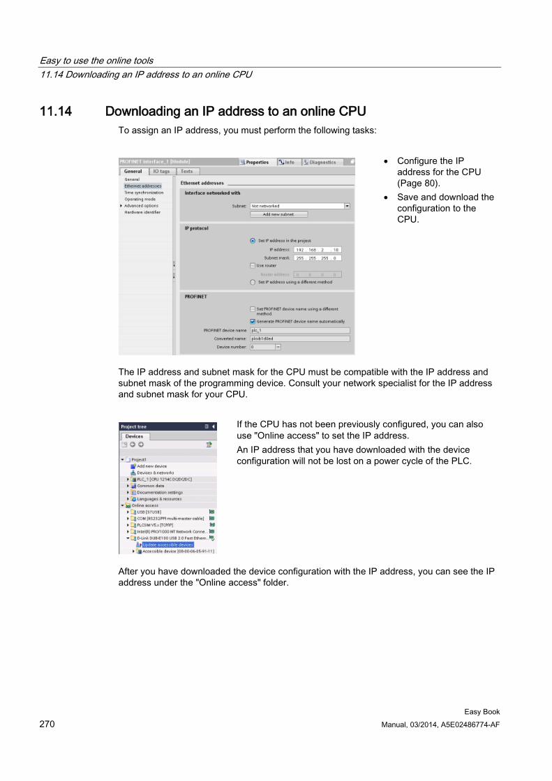
Easy to use the online tools 11.14 Downloading an IP address to an online CPU
Easy Book 270 Manual, 03/2014, A5E02486774-AF
11.14 Downloading an IP address to an online CPU To assign an IP address, you must perform the following tasks:
• Configure the IP address for the CPU (Page 80).
• Save and download the configuration to the CPU.
The IP address and subnet mask for the CPU must be compatible with the IP address and subnet mask of the programming device. Consult your network specialist for the IP address and subnet mask for your CPU.
If the CPU has not been previously configured, you can also use "Online access" to set the IP address. An IP address that you have downloaded with the device configuration will not be lost on a power cycle of the PLC.
After you have downloaded the device configuration with the IP address, you can see the IP address under the "Online access" folder.
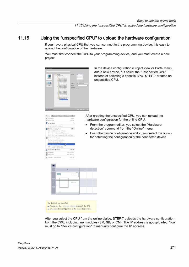
Easy to use the online tools 11.15 Using the "unspecified CPU" to upload the hardware configuration
Easy Book Manual, 03/2014, A5E02486774-AF 271
11.15 Using the "unspecified CPU" to upload the hardware configuration If you have a physical CPU that you can connect to the programming device, it is easy to upload the configuration of the hardware.
You must first connect the CPU to your programming device, and you must create a new project.
In the device configuration (Project view or Portal view), add a new device, but select the "unspecified CPU" instead of selecting a specific CPU. STEP 7 creates an unspecified CPU.
After creating the unspecified CPU, you can upload the hardware configuration for the online CPU. • From the program editor, you select the "Hardware
detection" command from the "Online" menu. • From the device configuration editor, you select the option
for detecting the configuration of the connected device
After you select the CPU from the online dialog, STEP 7 uploads the hardware configuration from the CPU, including any modules (SM, SB, or CM). The IP address is not uploaded. You must go to "Device configuration" to manually configure the IP address.
Easy to use the online tools 11.16 Downloading in RUN mode
Easy Book 272 Manual, 03/2014, A5E02486774-AF
11.16 Downloading in RUN mode The CPU supports "Download in RUN mode". This capability is intended to allow you to make small changes to a user program with minimal disturbance to the process being controlled by the program. However, implementing this capability also allows massive program changes that could be disruptive or even dangerous.
WARNING
Risks with downloading in RUN mode
When you download changes to the CPU in RUN mode, the changes immediately affect process operation. Changing the program in RUN mode can result in unexpected system operation, which could cause death or serious injury to personnel, and/or damage to equipment.
Only authorized personnel who understand the effects of RUN mode changes on system operation should perform a download in RUN mode.
The "Download in RUN mode" feature allows you to make changes to a program and download them to your CPU without switching to STOP mode:
● You can make minor changes to your current process without having to shut down (for example, change a parameter value).
● You can debug a program more quickly with this feature (for example, invert the logic for a normally open or normally closed switch).
You can make the following program block and tag changes and download them in RUN mode:
● Create, overwrite, and delete Functions (FC), Function Blocks (FB), and Tag tables.
● Create, delete, and overwrite Data Blocks (DB) and instance data blocks for Function Blocks (FB). You can add to DB structures and download them in RUN mode. The CPU can maintain the values of existing block tags and initialize the new data block tags to their initial values, or the CPU can set all data block tags to initial values, depending on your configuration settings. You cannot download a web server DB (control or fragment) in RUN mode.
● Overwrite Organization Blocks (OB); however, you cannot create or delete OBs.
You can download a maximum number of twenty blocks in RUN mode at one time. If you must download more than twenty blocks, you must place the CPU in STOP mode.
If you download changes to a real process (as opposed to a simulated process, which you might do in the course of debugging a program), it is vital to think through the possible safety consequences to machines and machine operators before you download.
Note
If the CPU is in RUN mode and program changes have been made, STEP 7 always tries to download in RUN first. If you do not want this to happen, you must put the CPU into STOP.
If the changes made are not supported in "Download in RUN", STEP 7 prompts the user that the CPU must go to STOP.
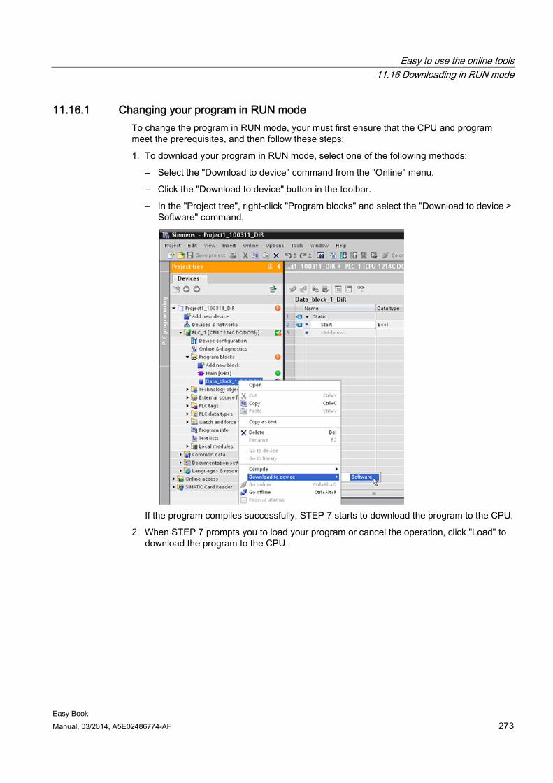
Easy to use the online tools 11.16 Downloading in RUN mode
Easy Book Manual, 03/2014, A5E02486774-AF 273
11.16.1 Changing your program in RUN mode To change the program in RUN mode, your must first ensure that the CPU and program meet the prerequisites, and then follow these steps:
1. To download your program in RUN mode, select one of the following methods:
– Select the "Download to device" command from the "Online" menu.
– Click the "Download to device" button in the toolbar.
– In the "Project tree", right-click "Program blocks" and select the "Download to device > Software" command.
If the program compiles successfully, STEP 7 starts to download the program to the CPU.
2. When STEP 7 prompts you to load your program or cancel the operation, click "Load" to download the program to the CPU.

Easy to use the online tools 11.17 Tracing and recording CPU data on trigger conditions
Easy Book 274 Manual, 03/2014, A5E02486774-AF
11.17 Tracing and recording CPU data on trigger conditions STEP 7 provides trace and logic analyzer functions with which you can configure variables for the PLC to trace and record. You can then upload the recorded trace data to your programming device and use STEP 7 tools to analyze, manage, and graph your data. You use the Traces folder in the STEP 7 project tree to create and manage traces.
The following figure shows the various steps of the trace feature:
① Configure the trace in the trace editor of STEP 7. You can configure the data values to record,
the recording duration, the recording frequency, and the trigger condition. ② Transfer the trace configuration from STEP 7 to the PLC. ③ The PLC executes the program, and when the trigger condition occurs, begins recording the
trace data. ④ Transfer the recorded values from the PLC to STEP 7. ⑤ Use the tools in STEP 7 to analyze the data, display it graphically, and save it.
Note that the trace feature is only available as of V4.0 of the S7-1200 CPU.
See the STEP 7 information system for details about how to program a trace, how to download the configuration, upload the trace data, and display the data in the logic analyzer.
Easy Book Manual, 03/2014, A5E02486774-AF 275
IO-Link is easy 12 12.1 Overview of IO-Link technology
IO-Link is an innovative communication technology for sensors and actuators defined by the PROFIBUS user organization (PNO). IO-Link is an international standard according to IEC 61131-9. It is based on a point-to-point connection between the sensors and actuators (slaves) and the controller (master). It does not therefore represent a bus system, but is an upgrade of the conventional point-to-point connection.
In addition to cyclic operating data, extensive parameter and diagnostic data is transmitted by the connected sensors/actuators. The same 3-wire connecting cable that is used for standard sensor technology is used for data transmission.
12.2 Components of an IO-Link system An IO-Link system consists of IO-Link devices (usually sensors, actuators, or combinations thereof), a standard 3-wire sensor/actuator cable, and an IO-Link master. The master can be a device with any design and degree of protection.
An IO-Link master can have one or more ports. The SM 1278 4xIO-Link Master has four ports. One IO-Link device or one standard sensor/actuator can be connected to each port. IO-Link is a point-to-point communication system.
12.3 After power-up At power-up, the IO-Link device is always in SIO mode (standard I/O mode). The ports of the master can have different configurations. See the IO-Link chapter in the S7-1200 System Manual for details.
If a port is set to SIO mode, the master acts on this port like a normal digital input. If the port is set to IO-Link mode (communication mode), the master tries to find the connected IO-Link device. This process is called wake-up.
During wake-up, the master sends a defined signal and waits for the slave device to respond. Initially, the master attempts to do this with the highest possible baud rate. If this is unsuccessful, the master tries the next lower baud rate. The master tries to address the device three times with each baud rate. The device always supports only one defined baud rate. If the master receives a response (that is, if the device has been woken up), both will start communication. At first, they exchange the communication parameters, and then they start the cyclical exchange of process data.
If the slave device is removed during operation, the master detects the communication abort, reports it with fieldbus specificity to the controller, and attempts to wake up the device again cyclically. After another successful wake-up, the communication parameters are read out again, validated if applicable, and then the cyclic communication channel starts again.
IO-Link is easy 12.4 IO-Link protocol
Easy Book 276 Manual, 03/2014, A5E02486774-AF
12.4 IO-Link protocol The IO-Link system can exchange three types of data:
● Cyclic process data (process data inputs, outputs) → Cyclic data
● Device parameters (on-request data objects) → Acyclic data
● Events → Acyclic data
The IO-Link device only sends data after being requested by the IO-Link master to do so. Process data is sent after the IDLE frame of the master, and the master explicitly requests device parameter data and events.
12.5 Configuration in the fieldbus The IO-Link master appears on the fieldbus as a normal fieldbus node and is integrated via the appropriate device description in the relevant network configurator. These files describe the communication properties and other properties of the IO-Link master, such as the number of ports. They do not indicate which IO-Link devices are connected.
However, the IO-Link Device Description (IODD) has been defined for full transparent representation of the system architecture up to the IO-Link device. With the help of the IODD and the IO-Link configuration tool S7-PCT, you can configure which IO-Link device is connected to which port of your IO-Link master.
See the S7-PCT help system and the S7-1200 System Manual for detailed configuration information.
12.6 IO-Link and your STEP 7 program The IO-Link master programs acyclic communication with an IO-Link device using the IOL_CALL function block (FB) in your STEP 7 S7-1200 controller program. The IOL_CALL FB indicates the IO-Link master your program uses, and which ports the master uses for data exchange.
Visit the Siemens Industry Online Support website (http://support.automation.siemens.com) for details on working with the IOL_CALL FB. Enter "IO-Link" in the website's search box to access information about IO-Link products and their use.
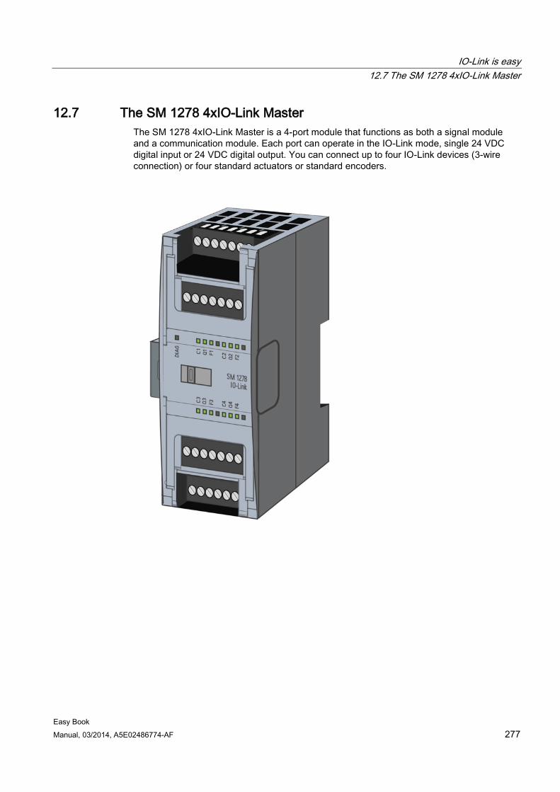
IO-Link is easy 12.7 The SM 1278 4xIO-Link Master
Easy Book Manual, 03/2014, A5E02486774-AF 277
12.7 The SM 1278 4xIO-Link Master The SM 1278 4xIO-Link Master is a 4-port module that functions as both a signal module and a communication module. Each port can operate in the IO-Link mode, single 24 VDC digital input or 24 VDC digital output. You can connect up to four IO-Link devices (3-wire connection) or four standard actuators or standard encoders.
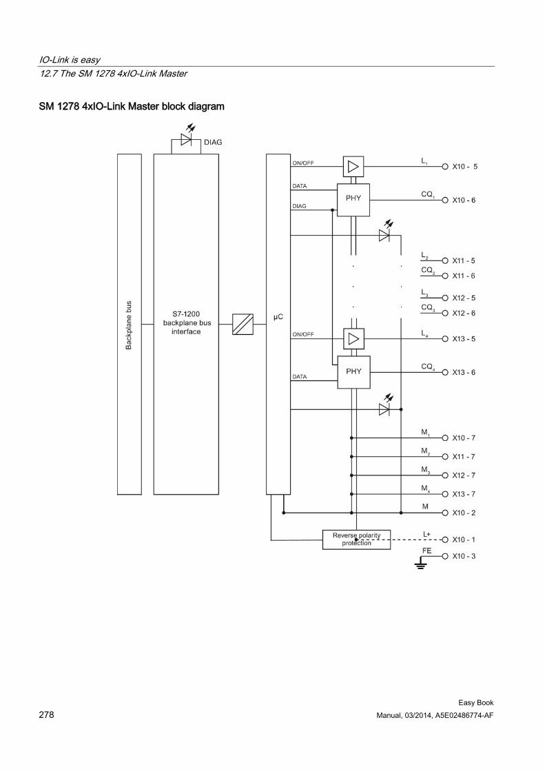
IO-Link is easy 12.7 The SM 1278 4xIO-Link Master
Easy Book 278 Manual, 03/2014, A5E02486774-AF
SM 1278 4xIO-Link Master block diagram
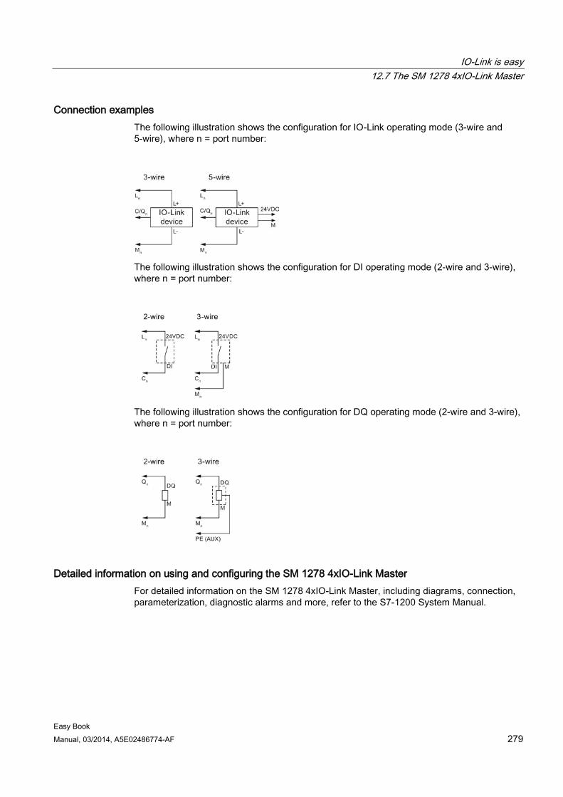
IO-Link is easy 12.7 The SM 1278 4xIO-Link Master
Easy Book Manual, 03/2014, A5E02486774-AF 279
Connection examples The following illustration shows the configuration for IO-Link operating mode (3-wire and 5-wire), where n = port number:
The following illustration shows the configuration for DI operating mode (2-wire and 3-wire), where n = port number:
The following illustration shows the configuration for DQ operating mode (2-wire and 3-wire), where n = port number:
Detailed information on using and configuring the SM 1278 4xIO-Link Master For detailed information on the SM 1278 4xIO-Link Master, including diagrams, connection, parameterization, diagnostic alarms and more, refer to the S7-1200 System Manual.

IO-Link is easy 12.7 The SM 1278 4xIO-Link Master
Easy Book 280 Manual, 03/2014, A5E02486774-AF
Easy Book Manual, 03/2014, A5E02486774-AF 281
Technical specifications A A.1 General technical specifications
Standards compliance The S7-1200 automation system design conforms with the following standards and test specifications. The test criteria for the S7-1200 automation system are based on these standards and test specifications.
Note that not all S7-1200 models may be certified to these standards, and certification status may change without notification. It is your responsibility to determine applicable certifications by referring to the ratings marked on the product. Consult your local Siemens representative if you need additional information related to the latest listing of exact approvals by part number.
CE approval The S7-1200 Automation System satisfies requirements and safety related objectives according to the EC directives listed below, and conforms to the harmonized European standards (EN) for the programmable controllers listed in the Official Journals of the European Community.
● EC Directive 2006/95/EC (Low Voltage Directive) "Electrical Equipment Designed for Use within Certain Voltage Limits"
– EN 61131-2:2007 Programmable controllers - Equipment requirements and tests
● EC Directive 2004/108/EC (EMC Directive) "Electromagnetic Compatibility"
– Emission standard EN 61000-6-4:2007: Industrial Environment
– Immunity standard EN 61000-6-2:2005: Industrial Environment
● EC Directive 94/9/EC (ATEX) "Equipment and Protective Systems Intended for Use in Potentially Explosive Atmosphere"
– EN 60079-15:2005: Type of Protection 'n'
The CE Declaration of Conformity is held on file available to competent authorities at:
Siemens AG IA AS RD ST PLC Amberg Werner-von-Siemens-Str. 50 D92224 Amberg Germany
Technical specifications A.1 General technical specifications
Easy Book 282 Manual, 03/2014, A5E02486774-AF
cULus approval Underwriters Laboratories Inc. complying with:
● Underwriters Laboratories, Inc.: UL 508 Listed (Industrial Control Equipment)
● Canadian Standards Association: CSA C22.2 Number 142 (Process Control Equipment)
Note
The SIMATIC S7-1200 series meets the CSA standard.
The cULus logo indicates that the S7-1200 has been examined and certified by Underwriters Laboratories (UL) to standards UL 508 and CSA 22.2 No. 142.
FM approval Factory Mutual Research (FM) Approval Standard Class Number 3600 and 3611 Approved for use in: Class I, Division 2, Gas Group A, B, C, D, Temperature Class T3C Ta = 60 °C Class I, Zone 2, IIC, Temperature Class T3 Ta = 60 °C Canadian Class I, Zone 2 Installation per CEC 18-150
IMPORTANT EXCEPTION: See Technical Specifications for the number of inputs or outputs allowed on simultaneously. Some models are de-rated for Ta = 60 °C.
WARNING
Substitution of components can impair the suitability for Class I, Division 2 and Zone 2.
Repair of units should only be performed by an authorized Siemens Service Center.
ATEX approval ATEX approval applies to DC models only. ATEX approval does not apply to AC and Relay models.
EN 60079-0:2009: Explosive Atmospheres - General Requirements
EN 60079-15:2010: Electrical Apparatus for Potentially Explosive Atmospheres; Type of protection 'nA' II 3 G Ex nA IIC T4 or T3 Gc
Install modules in a suitable enclosure providing a minimum degree of protection of IP54 according to EN 60529, or in a location providing an equivalent degree of protection.
Attached cables and conductors should be rated for the actual temperature measured under rated conditions.
The installation should ensure that transients are limited to less than 119 V. See Surge immunity in this section.
IMPORTANT EXCEPTION: See Technical Specifications for the number of inputs or outputs allowed on simultaneously. Some models are de-rated for Ta = 60 °C.
Technical specifications A.1 General technical specifications
Easy Book Manual, 03/2014, A5E02486774-AF 283
C-Tick approval The S7-1200 automation system satisfies requirements of standards to AS/NZS 2064 (Class A).
Korea Certification The S7-1200 automation system satisfies the requirements of the Korean Certification (KC Mark). It has been defined as Class A Equipment and is intended for industrial applications and has not been considered for home use.
Maritime approval The S7-1200 products are periodically submitted for special agency approvals related to specific markets and applications. Consult your local Siemens representative if you need additional information related to the latest listing of exact approvals by part number.
Classification societies:
● ABS (American Bureau of Shipping)
● BV (Bureau Veritas)
● DNV (Det Norske Veritas)
● GL (Germanischer Lloyd)
● LRS (Lloyds Register of Shipping)
● Class NK (Nippon Kaiji Kyokai)
● Korean Register of Shipping
Industrial environments The S7-1200 automation system is designed for use in industrial environments.
Table A- 1 Industrial environments
Application field Noise emission requirements Noise immunity requirements Industrial EN 61000-6-4:2007 EN 61000-6-2:2005
Technical specifications A.1 General technical specifications
Easy Book 284 Manual, 03/2014, A5E02486774-AF
Electromagnetic compatibility Electromagnetic Compatibility (EMC) is the ability of an electrical device to operate as intended in an electromagnetic environment and to operate without emitting levels of electromagnetic interference (EMI) that may disturb other electrical devices in the vicinity.
Table A- 2 Immunity per EN 61000-6-2
Electromagnetic compatibility - Immunity per EN 61000-6-2 EN 61000-4-2 Electrostatic discharge
8 kV air discharge to all surfaces 6 kV contact discharge to exposed conductive surfaces
EN 61000-4-3 Radiated, radio-frequency, electromagnetic field immunity test
80 to 1000 MHz, 10 V/m, 80% AM at 1 kHz 1.4 to 2.0 GHz, 3 V/m, 80% AM at 1 kHz 2.0 to 2.7 GHz, 1 V/m, 80% AM at 1 kHz
EN 61000-4-4 Fast transient bursts
2 kV, 5 kHz with coupling network to AC and DC system power 2 kV, 5 kHz with coupling clamp to I/O
EN 6100-4-5 Surge immunity
AC systems - 2 kV common mode, 1 kV differential mode DC systems - 2 kV common mode, 1 kV differential mode For DC systems, refer to Surge immunity below
EN 61000-4-6 Conducted disturbances
150 kHz to 80 MHz, 10 V RMS, 80% AM at 1kHz
EN 61000-4-11 Voltage dips
AC systems 0% for 1 cycle, 40% for 12 cycles and 70% for 30 cycles at 60 Hz
Surge immunity Wiring systems subject to surges from lightning strike coupling must be equipped with external protection. One specification for evaluation of protection from lightning type surges is found in EN 61000-4-5, with operational limits established by EN 61000-6-2. S7-1200 DC CPUs and signal modules require external protection to maintain safe operation when subject to surge voltages defined by this standard.
Listed below are some devices that support the needed surge immunity protection. These devices only provide the protection if they are properly installed according to the manufacturer's recommendations. Devices manufactured by other vendors with the same or better specifications can also be used:
● Supply Voltage, 24 VDC: DEHN, Inc., Type BVT AD 24, Part Number 918 402
● Digital Inputs, 24 VDC: DEHN, Inc., Type DCO RK E 24, Part Number 919 988
● Digital Outputs, 24 VDC: DEHN, Inc., Type DCO RK E 24, Part Number 919 988
● Analog Inputs: DEHN, Inc., Type BXT ML4 BD12, Part Number 920 342
● Analog Outputs: DEHN, Inc., Type DCO RK E 12, Part Number 919 987
● Ethernet: DEHN, Inc., Type DPA M CAT6 RJ45S 48, Part Number 929 100
● RS-232: DEHN, Inc., Type DCO RK E 12, Part Number 919 987
● RS-485: DEHN, Inc., Type BXT ML2 BE HFS 5, Part Number 920 270
● Relay Outputs: None required
Technical specifications A.1 General technical specifications
Easy Book Manual, 03/2014, A5E02486774-AF 285
Table A- 3 Conducted and radiated emissions per EN 61000-6-4
Electromagnetic compatibility - Conducted and radiated emissions per EN 61000-6-4 Conducted Emissions EN 55011, Class A, Group 1
0.15 MHz to 0.5 MHz <79dB (μV) quasi-peak; <66 dB (μV) average 0.5 MHz to 5 MHz <73dB (μV) quasi-peak; <60 dB (μV) average 5 MHz to 30 MHz <73dB (μV) quasi-peak; <60 dB (μV) average
Radiated Emissions EN 55011, Class A, Group 1
30 MHz to 230 MHz <40dB (μV/m) quasi-peak; measured at 10m 230 MHz to 1 GHz <47dB (μV/m) quasi-peak; measured at 10m
Environmental conditions
Table A- 4 Transport and storage
Environmental conditions - Transport and storage EN 60068-2-2, Test Bb, Dry heat and EN 60068-2-1, Test Ab, Cold
-40 °C to +70 °C
EN 60068-2-30, Test Db, Damp heat 25 °C to 55 °C, 95% humidity EN 60068-2-14, Test Na, temperature shock -40 °C to +70 °C, dwell time 3 hours, 5 cycles EN 60068-2-32, Free fall 0.3 m, 5 times, product packaging Atmospheric pressure 1080 to 660h Pa (corresponding to an altitude of -1000 to 3500m)
Table A- 5 Operating conditions
Environmental conditions - Operating Ambient temperature range (Inlet Air 25 mm below unit)
-20 °C to 60 °C horizontal mounting -20 °C to 50 °C vertical mounting 95% non-condensing humidity Unless otherwise specified
Atmospheric pressure 1080 to 795 hPa (corresponding to an altitude of -1000 to 2000m) Concentration of contaminants S02: < 0.5 ppm; H2S: < 0.1 ppm; RH < 60% non-condensing EN 60068-2-14, Test Nb, temperature change 5 °C to 55 °C, 3 °C/minute EN 60068-2-27 Mechanical shock 15 G, 11 ms pulse, 6 shocks in each of 3 axis EN 60068-2-6 Sinusoidal vibration DIN rail mount: 3.5 mm from 5-9 Hz, 1G from 9 - 150 Hz
Panel Mount: 7.0 mm from 5-9 Hz, 2G from 9 to 150 Hz 10 sweeps each axis, 1 octave per minute
Technical specifications A.1 General technical specifications
Easy Book 286 Manual, 03/2014, A5E02486774-AF
Table A- 6 High potential isolation test
High potential isolation test 24 VDC / 5 VDC nominal circuits 115 VAC / 230 VAC circuits to ground 115 VAC / 230 VAC circuits to 115 VAC / 230 VAC circuits 115 VAC / 230 VAC circuits to 24 VDC / 5 VDC circuits Ethernet port to 24 VDC / 5 VDC circuits and ground1
520 VDC (type test of optical isolation boundaries) 1500 VAC 1500 VAC 1500 VAC (3000 VAC/4242 VDC type test) 1500 VAC (type test only)
1 Ethernet port isolation is designed to limit hazard during short term network faults to hazardous voltages. It does not conform to safety requirements for routine AC line voltage isolation.
Protection class ● Protection Class II according to EN 61131-2 (Protective conductor not required)
Degree of protection ● IP20 Mechanical Protection, EN 60529
● Protects against finger contact with high voltage as tested by standard probe. External protection required for dust, dirt, water and foreign objects of < 12.5mm in diameter.
Rated voltages
Table A- 7 Rated voltages
Rated voltage Tolerance 24 VDC 20.4 VDC to 28.8 VDC 120/230 VAC 85 VAC to 264 VAC, 47 to 63 Hz
Note
When a mechanical contact turns on output power to the S7-1200 CPU, or any digital signal module, it sends a "1" signal to the digital outputs for approximately 50 microseconds. This could cause unexpected machine or process operation which could result in death or serious injury to personnel and/or damage to equipment. You must plan for this, especially if you are using devices which respond to short duration pulses.
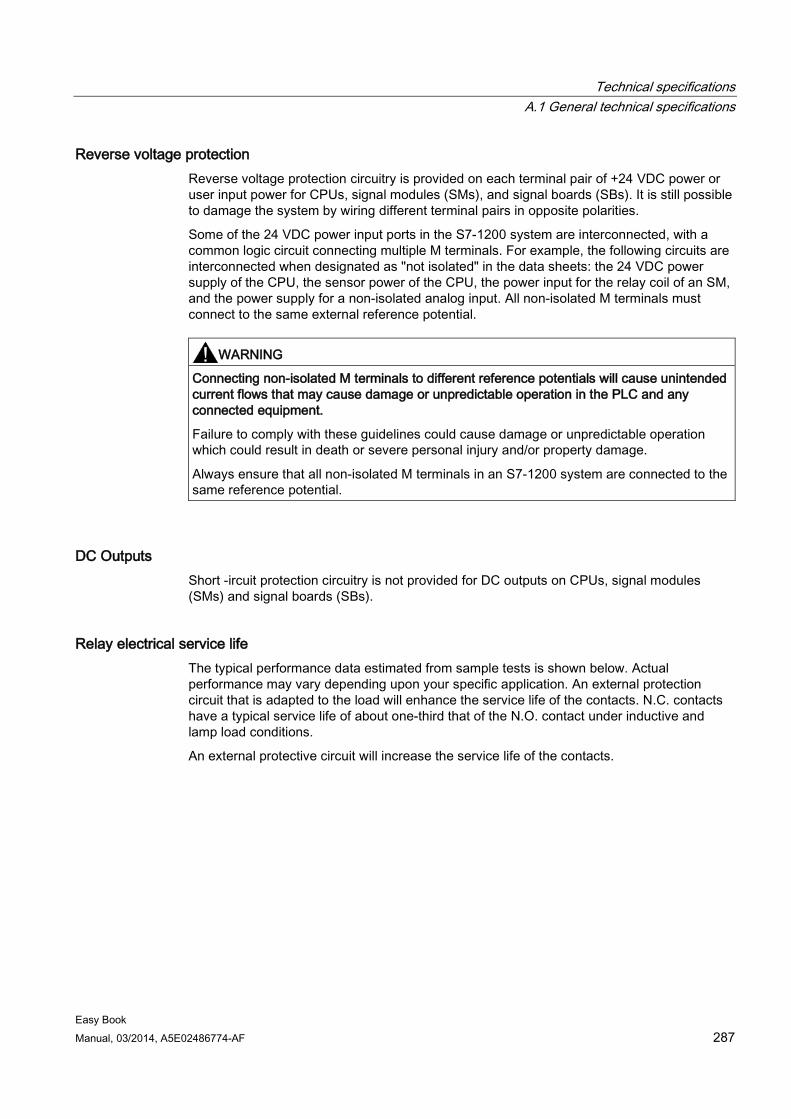
Technical specifications A.1 General technical specifications
Easy Book Manual, 03/2014, A5E02486774-AF 287
Reverse voltage protection Reverse voltage protection circuitry is provided on each terminal pair of +24 VDC power or user input power for CPUs, signal modules (SMs), and signal boards (SBs). It is still possible to damage the system by wiring different terminal pairs in opposite polarities.
Some of the 24 VDC power input ports in the S7-1200 system are interconnected, with a common logic circuit connecting multiple M terminals. For example, the following circuits are interconnected when designated as "not isolated" in the data sheets: the 24 VDC power supply of the CPU, the sensor power of the CPU, the power input for the relay coil of an SM, and the power supply for a non-isolated analog input. All non-isolated M terminals must connect to the same external reference potential.
WARNING
Connecting non-isolated M terminals to different reference potentials will cause unintended current flows that may cause damage or unpredictable operation in the PLC and any connected equipment.
Failure to comply with these guidelines could cause damage or unpredictable operation which could result in death or severe personal injury and/or property damage.
Always ensure that all non-isolated M terminals in an S7-1200 system are connected to the same reference potential.
DC Outputs Short -ircuit protection circuitry is not provided for DC outputs on CPUs, signal modules (SMs) and signal boards (SBs).
Relay electrical service life The typical performance data estimated from sample tests is shown below. Actual performance may vary depending upon your specific application. An external protection circuit that is adapted to the load will enhance the service life of the contacts. N.C. contacts have a typical service life of about one-third that of the N.O. contact under inductive and lamp load conditions.
An external protective circuit will increase the service life of the contacts.
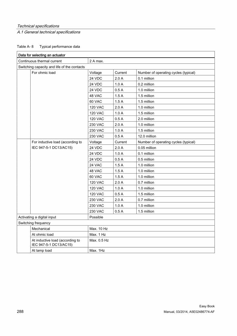
Technical specifications A.1 General technical specifications
Easy Book 288 Manual, 03/2014, A5E02486774-AF
Table A- 8 Typical performance data
Data for selecting an actuator Continuous thermal current 2 A max. Switching capacity and life of the contacts For ohmic load Voltage Current Number of operating cycles (typical)
24 VDC 2.0 A 0.1 million 24 VDC 1.0 A 0.2 million 24 VDC 0.5 A 1.0 million 48 VAC 1.5 A 1.5 million 60 VAC 1.5 A 1.5 million 120 VAC 2.0 A 1.0 million 120 VAC 1.0 A 1.5 million 120 VAC 0.5 A 2.0 million 230 VAC 2.0 A 1.0 million 230 VAC 1.0 A 1.5 million 230 VAC 0.5 A 12.0 million
For inductive load (according to IEC 947-5-1 DC13/AC15)
Voltage Current Number of operating cycles (typical) 24 VDC 2.0 A 0.05 million 24 VDC 1.0 A 0.1 million 24 VDC 0.5 A 0.5 million 24 VAC 1.5 A 1.0 million 48 VAC 1.5 A 1.0 million 60 VAC 1.5 A 1.0 million 120 VAC 2.0 A 0.7 million 120 VAC 1.0 A 1.0 million 120 VAC 0.5 A 1.5 million 230 VAC 2.0 A 0.7 million 230 VAC 1.0 A 1.0 million 230 VAC 0.5 A 1.5 million
Activating a digital input Possible Switching frequency
Mechanical Max. 10 Hz At ohmic load Max. 1 Hz At inductive load (according to IEC 947-5-1 DC13/AC15)
Max. 0.5 Hz
At lamp load Max. 1Hz
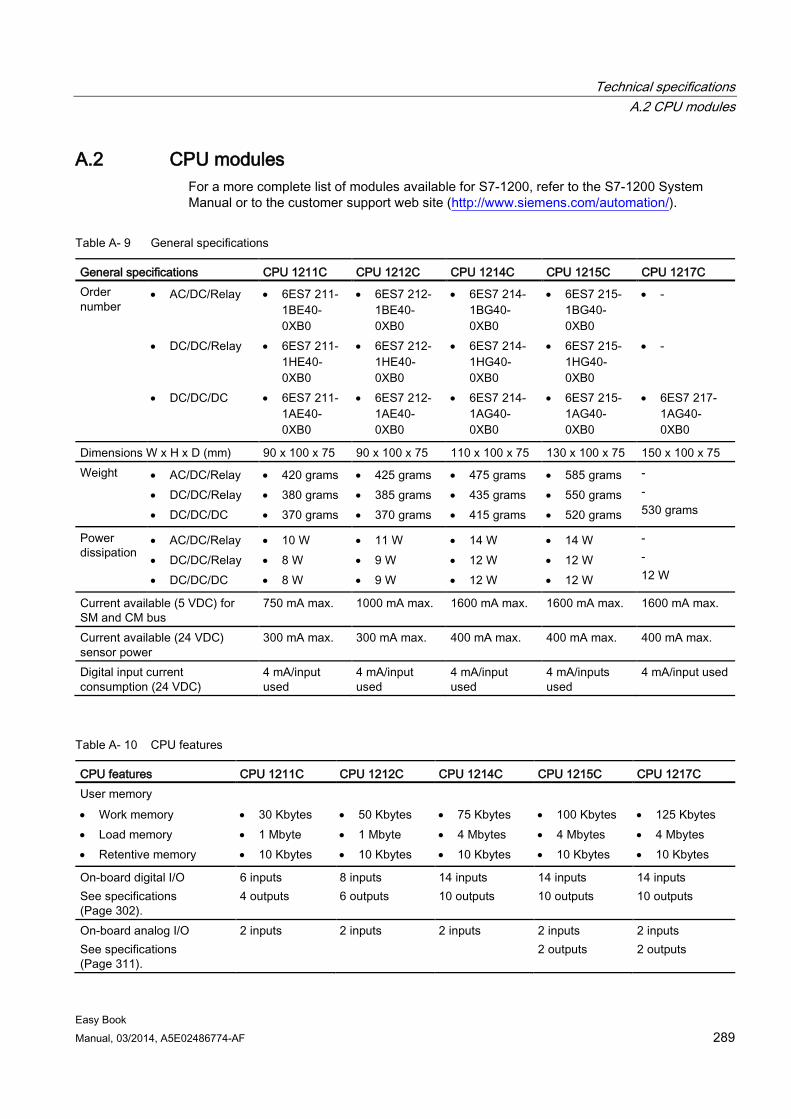
Technical specifications A.2 CPU modules
Easy Book Manual, 03/2014, A5E02486774-AF 289
A.2 CPU modules For a more complete list of modules available for S7-1200, refer to the S7-1200 System Manual or to the customer support web site (http://www.siemens.com/automation/).
Table A- 9 General specifications
General specifications CPU 1211C CPU 1212C CPU 1214C CPU 1215C CPU 1217C Order number
• AC/DC/Relay
• DC/DC/Relay
• DC/DC/DC
• 6ES7 211-1BE40-0XB0
• 6ES7 211-1HE40-0XB0
• 6ES7 211-1AE40-0XB0
• 6ES7 212-1BE40-0XB0
• 6ES7 212-1HE40-0XB0
• 6ES7 212-1AE40-0XB0
• 6ES7 214-1BG40-0XB0
• 6ES7 214-1HG40-0XB0
• 6ES7 214-1AG40-0XB0
• 6ES7 215-1BG40-0XB0
• 6ES7 215-1HG40-0XB0
• 6ES7 215-1AG40-0XB0
• -
• -
• 6ES7 217-1AG40-0XB0
Dimensions W x H x D (mm) 90 x 100 x 75 90 x 100 x 75 110 x 100 x 75 130 x 100 x 75 150 x 100 x 75 Weight • AC/DC/Relay
• DC/DC/Relay • DC/DC/DC
• 420 grams • 380 grams • 370 grams
• 425 grams • 385 grams • 370 grams
• 475 grams • 435 grams • 415 grams
• 585 grams • 550 grams • 520 grams
- - 530 grams
Power dissipation
• AC/DC/Relay • DC/DC/Relay • DC/DC/DC
• 10 W • 8 W • 8 W
• 11 W • 9 W • 9 W
• 14 W • 12 W • 12 W
• 14 W • 12 W • 12 W
- - 12 W
Current available (5 VDC) for SM and CM bus
750 mA max. 1000 mA max. 1600 mA max. 1600 mA max. 1600 mA max.
Current available (24 VDC) sensor power
300 mA max. 300 mA max. 400 mA max. 400 mA max. 400 mA max.
Digital input current consumption (24 VDC)
4 mA/input used
4 mA/input used
4 mA/input used
4 mA/inputs used
4 mA/input used
Table A- 10 CPU features
CPU features CPU 1211C CPU 1212C CPU 1214C CPU 1215C CPU 1217C User memory • Work memory • Load memory • Retentive memory
• 30 Kbytes • 1 Mbyte • 10 Kbytes
• 50 Kbytes • 1 Mbyte • 10 Kbytes
• 75 Kbytes • 4 Mbytes • 10 Kbytes
• 100 Kbytes • 4 Mbytes • 10 Kbytes
• 125 Kbytes • 4 Mbytes • 10 Kbytes
On-board digital I/O See specifications (Page 302).
6 inputs 4 outputs
8 inputs 6 outputs
14 inputs 10 outputs
14 inputs 10 outputs
14 inputs 10 outputs
On-board analog I/O See specifications (Page 311).
2 inputs 2 inputs 2 inputs 2 inputs 2 outputs
2 inputs 2 outputs
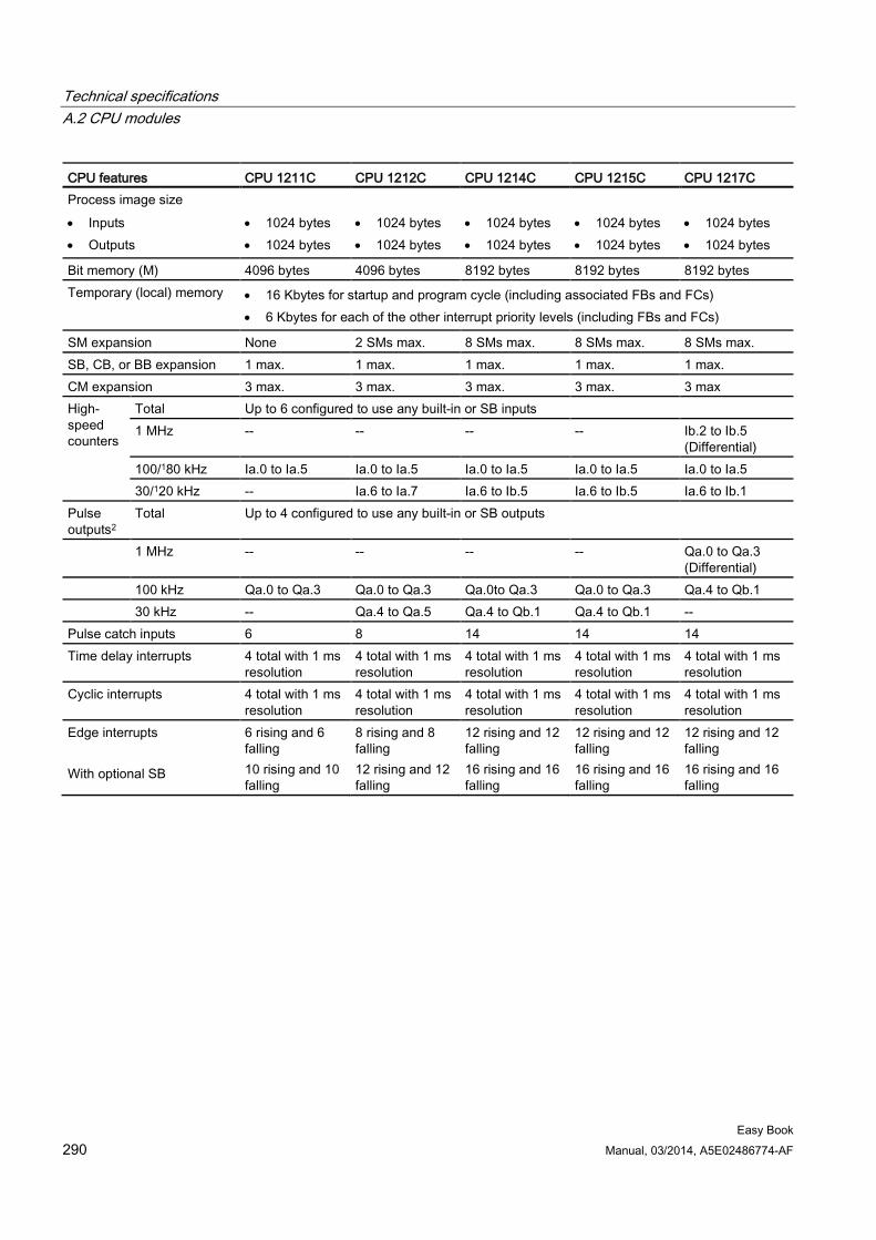
Technical specifications A.2 CPU modules
Easy Book 290 Manual, 03/2014, A5E02486774-AF
CPU features CPU 1211C CPU 1212C CPU 1214C CPU 1215C CPU 1217C Process image size • Inputs • Outputs
• 1024 bytes • 1024 bytes
• 1024 bytes • 1024 bytes
• 1024 bytes • 1024 bytes
• 1024 bytes • 1024 bytes
• 1024 bytes • 1024 bytes
Bit memory (M) 4096 bytes 4096 bytes 8192 bytes 8192 bytes 8192 bytes Temporary (local) memory • 16 Kbytes for startup and program cycle (including associated FBs and FCs)
• 6 Kbytes for each of the other interrupt priority levels (including FBs and FCs)
SM expansion None 2 SMs max. 8 SMs max. 8 SMs max. 8 SMs max. SB, CB, or BB expansion 1 max. 1 max. 1 max. 1 max. 1 max. CM expansion 3 max. 3 max. 3 max. 3 max. 3 max High-speed counters
Total Up to 6 configured to use any built-in or SB inputs 1 MHz -- -- -- -- Ib.2 to Ib.5
(Differential) 100/180 kHz Ia.0 to Ia.5 Ia.0 to Ia.5 Ia.0 to Ia.5 Ia.0 to Ia.5 Ia.0 to Ia.5 30/120 kHz -- Ia.6 to Ia.7 Ia.6 to Ib.5 Ia.6 to Ib.5 Ia.6 to Ib.1
Pulse outputs2
Total Up to 4 configured to use any built-in or SB outputs
1 MHz -- -- -- -- Qa.0 to Qa.3 (Differential)
100 kHz Qa.0 to Qa.3 Qa.0 to Qa.3 Qa.0to Qa.3 Qa.0 to Qa.3 Qa.4 to Qb.1 30 kHz -- Qa.4 to Qa.5 Qa.4 to Qb.1 Qa.4 to Qb.1 -- Pulse catch inputs 6 8 14 14 14 Time delay interrupts 4 total with 1 ms
resolution 4 total with 1 ms resolution
4 total with 1 ms resolution
4 total with 1 ms resolution
4 total with 1 ms resolution
Cyclic interrupts 4 total with 1 ms resolution
4 total with 1 ms resolution
4 total with 1 ms resolution
4 total with 1 ms resolution
4 total with 1 ms resolution
Edge interrupts With optional SB
6 rising and 6 falling 10 rising and 10 falling
8 rising and 8 falling 12 rising and 12 falling
12 rising and 12 falling 16 rising and 16 falling
12 rising and 12 falling 16 rising and 16 falling
12 rising and 12 falling 16 rising and 16 falling
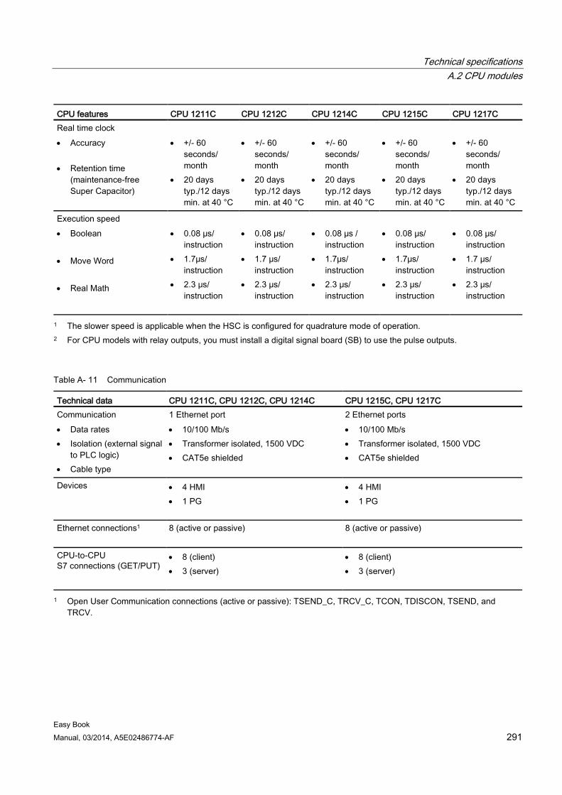
Technical specifications A.2 CPU modules
Easy Book Manual, 03/2014, A5E02486774-AF 291
CPU features CPU 1211C CPU 1212C CPU 1214C CPU 1215C CPU 1217C Real time clock • Accuracy
• Retention time
(maintenance-free Super Capacitor)
• +/- 60
seconds/ month
• 20 days typ./12 days min. at 40 °C
• +/- 60
seconds/ month
• 20 days typ./12 days min. at 40 °C
• +/- 60
seconds/ month
• 20 days typ./12 days min. at 40 °C
• +/- 60
seconds/ month
• 20 days typ./12 days min. at 40 °C
• +/- 60
seconds/ month
• 20 days typ./12 days min. at 40 °C
Execution speed • Boolean • Move Word • Real Math
• 0.08 μs/
instruction • 1.7μs/
instruction • 2.3 μs/
instruction
• 0.08 μs/
instruction • 1.7 μs/
instruction • 2.3 μs/
instruction
• 0.08 μs /
instruction • 1.7μs/
instruction • 2.3 μs/
instruction
• 0.08 μs/
instruction • 1.7μs/
instruction • 2.3 μs/
instruction
• 0.08 μs/
instruction • 1.7 μs/
instruction • 2.3 μs/
instruction
1 The slower speed is applicable when the HSC is configured for quadrature mode of operation. 2 For CPU models with relay outputs, you must install a digital signal board (SB) to use the pulse outputs.
Table A- 11 Communication
Technical data CPU 1211C, CPU 1212C, CPU 1214C CPU 1215C, CPU 1217C Communication • Data rates • Isolation (external signal
to PLC logic) • Cable type
1 Ethernet port • 10/100 Mb/s • Transformer isolated, 1500 VDC • CAT5e shielded
2 Ethernet ports • 10/100 Mb/s • Transformer isolated, 1500 VDC • CAT5e shielded
Devices • 4 HMI • 1 PG
• 4 HMI • 1 PG
Ethernet connections1 8 (active or passive) 8 (active or passive)
CPU-to-CPU S7 connections (GET/PUT)
• 8 (client) • 3 (server)
• 8 (client) • 3 (server)
1 Open User Communication connections (active or passive): TSEND_C, TRCV_C, TCON, TDISCON, TSEND, and TRCV.
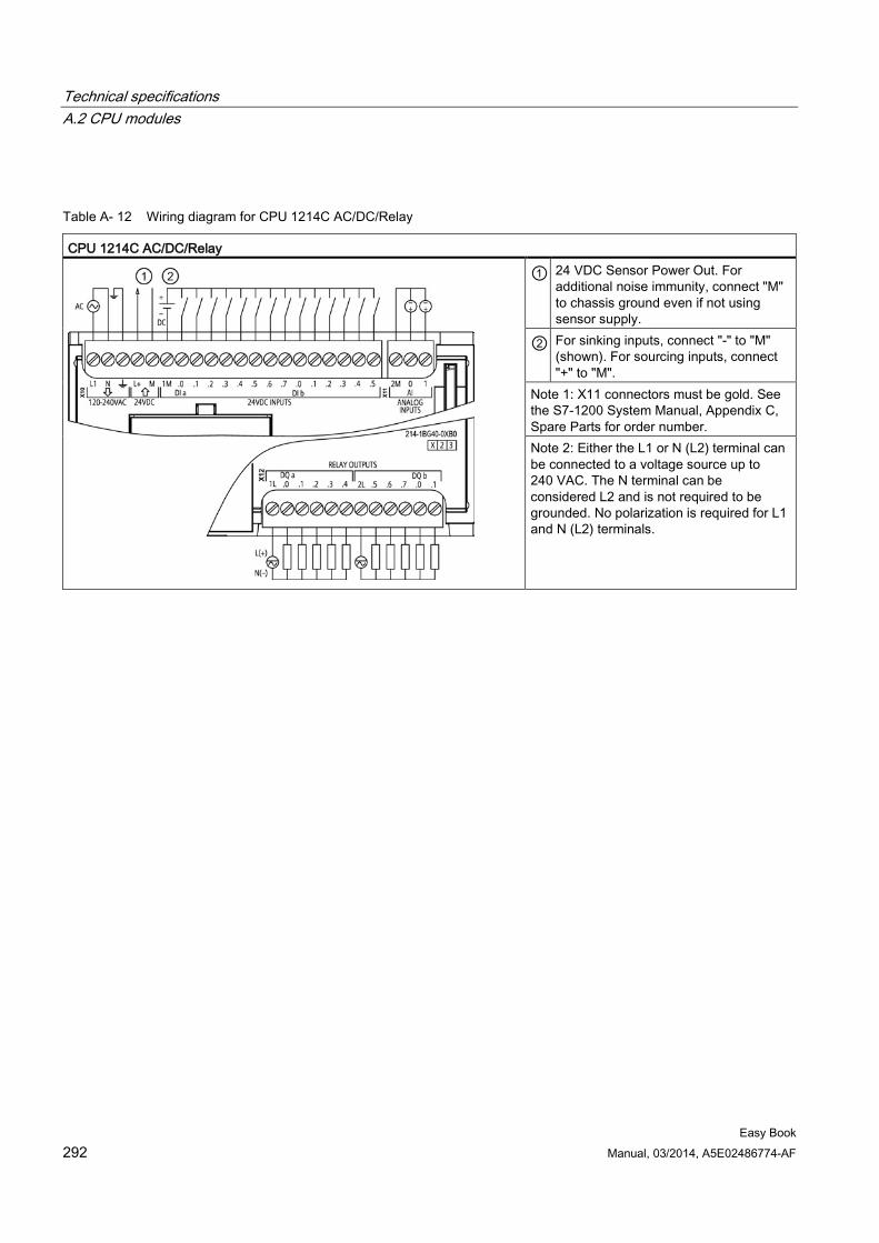
Technical specifications A.2 CPU modules
Easy Book 292 Manual, 03/2014, A5E02486774-AF
Table A- 12 Wiring diagram for CPU 1214C AC/DC/Relay
CPU 1214C AC/DC/Relay
① 24 VDC Sensor Power Out. For additional noise immunity, connect "M" to chassis ground even if not using sensor supply.
② For sinking inputs, connect "-" to "M" (shown). For sourcing inputs, connect "+" to "M".
Note 1: X11 connectors must be gold. See the S7-1200 System Manual, Appendix C, Spare Parts for order number. Note 2: Either the L1 or N (L2) terminal can be connected to a voltage source up to 240 VAC. The N terminal can be considered L2 and is not required to be grounded. No polarization is required for L1 and N (L2) terminals.
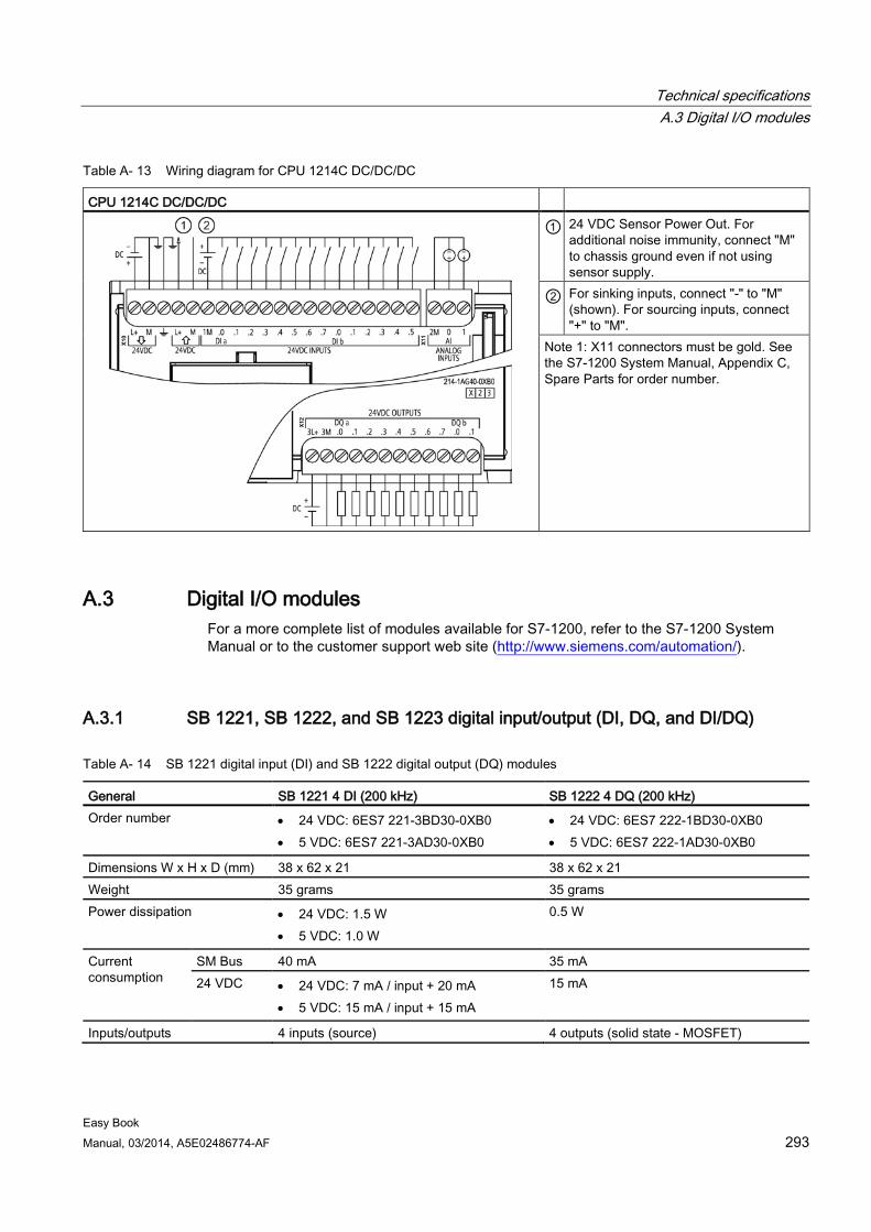
Technical specifications A.3 Digital I/O modules
Easy Book Manual, 03/2014, A5E02486774-AF 293
Table A- 13 Wiring diagram for CPU 1214C DC/DC/DC
CPU 1214C DC/DC/DC
① 24 VDC Sensor Power Out. For additional noise immunity, connect "M" to chassis ground even if not using sensor supply.
② For sinking inputs, connect "-" to "M" (shown). For sourcing inputs, connect "+" to "M".
Note 1: X11 connectors must be gold. See the S7-1200 System Manual, Appendix C, Spare Parts for order number.
A.3 Digital I/O modules For a more complete list of modules available for S7-1200, refer to the S7-1200 System Manual or to the customer support web site (http://www.siemens.com/automation/).
A.3.1 SB 1221, SB 1222, and SB 1223 digital input/output (DI, DQ, and DI/DQ)
Table A- 14 SB 1221 digital input (DI) and SB 1222 digital output (DQ) modules
General SB 1221 4 DI (200 kHz) SB 1222 4 DQ (200 kHz) Order number • 24 VDC: 6ES7 221-3BD30-0XB0
• 5 VDC: 6ES7 221-3AD30-0XB0 • 24 VDC: 6ES7 222-1BD30-0XB0 • 5 VDC: 6ES7 222-1AD30-0XB0
Dimensions W x H x D (mm) 38 x 62 x 21 38 x 62 x 21 Weight 35 grams 35 grams Power dissipation • 24 VDC: 1.5 W
• 5 VDC: 1.0 W
0.5 W
Current consumption
SM Bus 40 mA 35 mA 24 VDC • 24 VDC: 7 mA / input + 20 mA
• 5 VDC: 15 mA / input + 15 mA
15 mA
Inputs/outputs 4 inputs (source) 4 outputs (solid state - MOSFET)
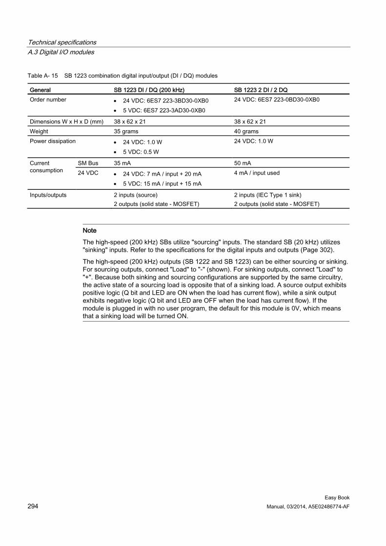
Technical specifications A.3 Digital I/O modules
Easy Book 294 Manual, 03/2014, A5E02486774-AF
Table A- 15 SB 1223 combination digital input/output (DI / DQ) modules
General SB 1223 DI / DQ (200 kHz) SB 1223 2 DI / 2 DQ Order number • 24 VDC: 6ES7 223-3BD30-0XB0
• 5 VDC: 6ES7 223-3AD30-0XB0
24 VDC: 6ES7 223-0BD30-0XB0
Dimensions W x H x D (mm) 38 x 62 x 21 38 x 62 x 21 Weight 35 grams 40 grams Power dissipation • 24 VDC: 1.0 W
• 5 VDC: 0.5 W
24 VDC: 1.0 W
Current consumption
SM Bus 35 mA 50 mA 24 VDC • 24 VDC: 7 mA / input + 20 mA
• 5 VDC: 15 mA / input + 15 mA
4 mA / input used
Inputs/outputs 2 inputs (source) 2 outputs (solid state - MOSFET)
2 inputs (IEC Type 1 sink) 2 outputs (solid state - MOSFET)
Note
The high-speed (200 kHz) SBs utilize "sourcing" inputs. The standard SB (20 kHz) utilizes "sinking" inputs. Refer to the specifications for the digital inputs and outputs (Page 302).
The high-speed (200 kHz) outputs (SB 1222 and SB 1223) can be either sourcing or sinking. For sourcing outputs, connect "Load" to "-" (shown). For sinking outputs, connect "Load" to "+". Because both sinking and sourcing configurations are supported by the same circuitry, the active state of a sourcing load is opposite that of a sinking load. A source output exhibits positive logic (Q bit and LED are ON when the load has current flow), while a sink output exhibits negative logic (Q bit and LED are OFF when the load has current flow). If the module is plugged in with no user program, the default for this module is 0V, which means that a sinking load will be turned ON.
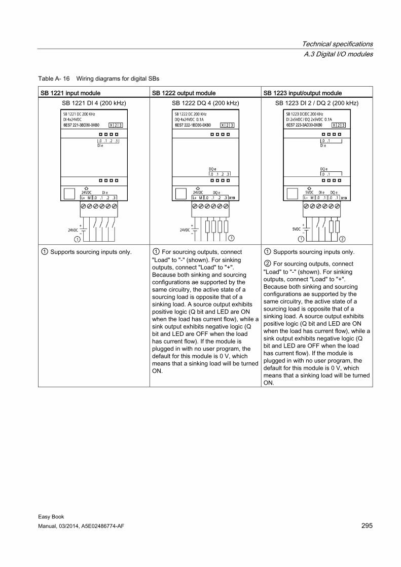
Technical specifications A.3 Digital I/O modules
Easy Book Manual, 03/2014, A5E02486774-AF 295
Table A- 16 Wiring diagrams for digital SBs
SB 1221 input module SB 1222 output module SB 1223 input/output module SB 1221 DI 4 (200 kHz)
SB 1222 DQ 4 (200 kHz)
SB 1223 DI 2 / DQ 2 (200 kHz)
① Supports sourcing inputs only. ① For sourcing outputs, connect
"Load" to "-" (shown). For sinking outputs, connect "Load" to "+". Because both sinking and sourcing configurations ae supported by the same circuitry, the active state of a sourcing load is opposite that of a sinking load. A source output exhibits positive logic (Q bit and LED are ON when the load has current flow), while a sink output exhibits negative logic (Q bit and LED are OFF when the load has current flow). If the module is plugged in with no user program, the default for this module is 0 V, which means that a sinking load will be turned ON.
① Supports sourcing inputs only.
② For sourcing outputs, connect "Load" to "-" (shown). For sinking outputs, connect "Load" to "+". Because both sinking and sourcing configurations ae supported by the same circuitry, the active state of a sourcing load is opposite that of a sinking load. A source output exhibits positive logic (Q bit and LED are ON when the load has current flow), while a sink output exhibits negative logic (Q bit and LED are OFF when the load has current flow). If the module is plugged in with no user program, the default for this module is 0 V, which means that a sinking load will be turned ON.
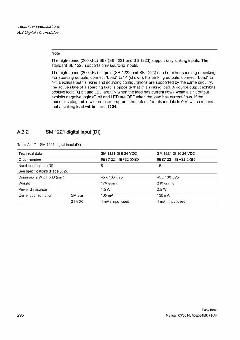
Technical specifications A.3 Digital I/O modules
Easy Book 296 Manual, 03/2014, A5E02486774-AF
Note
The high-speed (200 kHz) SBs (SB 1221 and SB 1223) support only sinking inputs. The standard SB 1223 supports only sourcing inputs.
The high-speed (200 kHz) outputs (SB 1222 and SB 1223) can be either sourcing or sinking. For sourcing outputs, connect "Load" to "-" (shown). For sinking outputs, connect "Load" to "+". Because both sinking and sourcing configurations are supported by the same circuitry, the active state of a sourcing load is opposite that of a sinking load. A source output exhibits positive logic (Q bit and LED are ON when the load has current flow), while a sink output exhibits negative logic (Q bit and LED are OFF when the load has current flow). If the module is plugged in with no user program, the default for this module is 0 V, which means that a sinking load will be turned ON.
A.3.2 SM 1221 digital input (DI)
Table A- 17 SM 1221 digital input (DI)
Technical data SM 1221 DI 8 24 VDC SM 1221 DI 16 24 VDC Order number 6ES7 221-1BF32-0XB0 6ES7 221-1BH32-0XB0 Number of inputs (DI) See specifications (Page 302).
8 16
Dimensions W x H x D (mm) 45 x 100 x 75 45 x 100 x 75 Weight 170 grams 210 grams Power dissipation 1.5 W 2.5 W Current consumption SM Bus 105 mA 130 mA
24 VDC 4 mA / input used 4 mA / input used
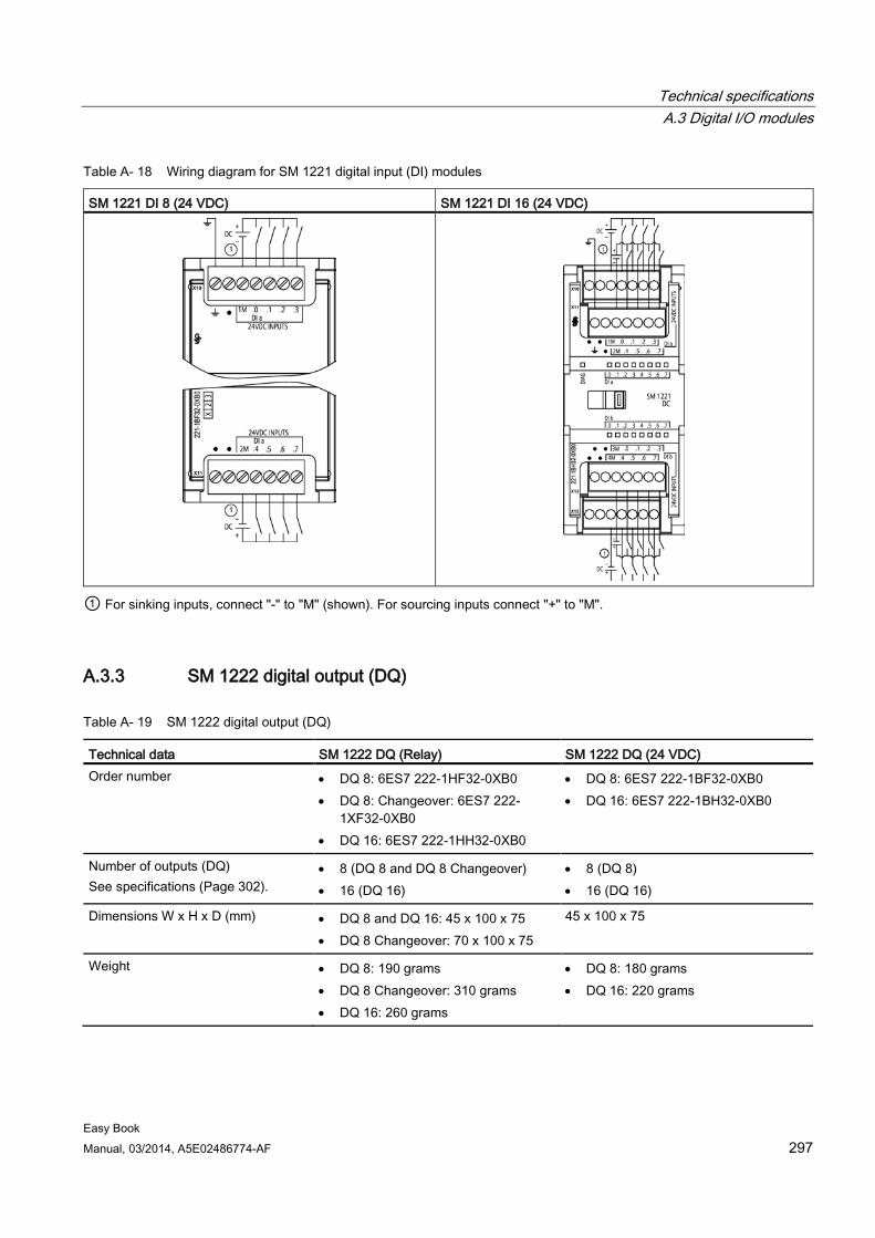
Technical specifications A.3 Digital I/O modules
Easy Book Manual, 03/2014, A5E02486774-AF 297
Table A- 18 Wiring diagram for SM 1221 digital input (DI) modules
SM 1221 DI 8 (24 VDC) SM 1221 DI 16 (24 VDC)
① For sinking inputs, connect "-" to "M" (shown). For sourcing inputs connect "+" to "M".
A.3.3 SM 1222 digital output (DQ)
Table A- 19 SM 1222 digital output (DQ)
Technical data SM 1222 DQ (Relay) SM 1222 DQ (24 VDC) Order number • DQ 8: 6ES7 222-1HF32-0XB0
• DQ 8: Changeover: 6ES7 222-1XF32-0XB0
• DQ 16: 6ES7 222-1HH32-0XB0
• DQ 8: 6ES7 222-1BF32-0XB0 • DQ 16: 6ES7 222-1BH32-0XB0
Number of outputs (DQ) See specifications (Page 302).
• 8 (DQ 8 and DQ 8 Changeover) • 16 (DQ 16)
• 8 (DQ 8) • 16 (DQ 16)
Dimensions W x H x D (mm) • DQ 8 and DQ 16: 45 x 100 x 75 • DQ 8 Changeover: 70 x 100 x 75
45 x 100 x 75
Weight • DQ 8: 190 grams • DQ 8 Changeover: 310 grams • DQ 16: 260 grams
• DQ 8: 180 grams • DQ 16: 220 grams
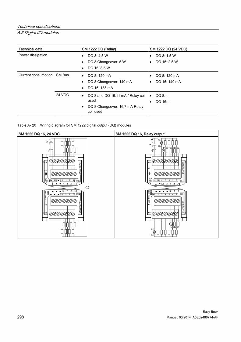
Technical specifications A.3 Digital I/O modules
Easy Book 298 Manual, 03/2014, A5E02486774-AF
Technical data SM 1222 DQ (Relay) SM 1222 DQ (24 VDC) Power dissipation • DQ 8: 4.5 W
• DQ 8 Changeover: 5 W • DQ 16: 8.5 W
• DQ 8: 1.5 W • DQ 16: 2.5 W
Current consumption SM Bus • DQ 8: 120 mA • DQ 8 Changeover: 140 mA • DQ 16: 135 mA
• DQ 8: 120 mA • DQ 16: 140 mA
24 VDC • DQ 8 and DQ 16:11 mA / Relay coil used
• DQ 8 Changeover: 16.7 mA Relay coil used
• DQ 8: -- • DQ 16: --
Table A- 20 Wiring diagram for SM 1222 digital output (DQ) modules
SM 1222 DQ 16, 24 VDC SM 1222 DQ 16, Relay output
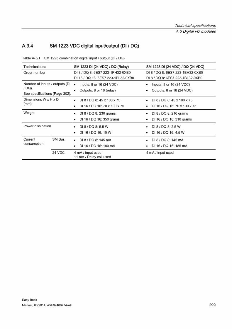
Technical specifications A.3 Digital I/O modules
Easy Book Manual, 03/2014, A5E02486774-AF 299
A.3.4 SM 1223 VDC digital input/output (DI / DQ)
Table A- 21 SM 1223 combination digital input / output (DI / DQ)
Technical data SM 1223 DI (24 VDC) / DQ (Relay) SM 1223 DI (24 VDC) / DQ (24 VDC) Order number DI 8 / DQ 8: 6ES7 223-1PH32-0XB0
DI 16 / DQ 16: 6ES7 223-1PL32-0XB0 DI 8 / DQ 8: 6ES7 223-1BH32-0XB0 DI 8 / DQ 8: 6ES7 223-1BL32-0XB0
Number of inputs / outputs (DI / DQ) See specifications (Page 302).
• Inputs: 8 or 16 (24 VDC) • Outputs: 8 or 16 (relay)
• Inputs: 8 or 16 (24 VDC) • Outputs: 8 or 16 (24 VDC)
Dimensions W x H x D (mm)
• DI 8 / DQ 8: 45 x 100 x 75 • DI 16 / DQ 16: 70 x 100 x 75
• DI 8 / DQ 8: 45 x 100 x 75 • DI 16 / DQ 16: 70 x 100 x 75
Weight • DI 8 / DQ 8: 230 grams • DI 16 / DQ 16: 350 grams
• DI 8 / DQ 8: 210 grams • DI 16 / DQ 16: 310 grams
Power dissipation • DI 8 / DQ 8: 5.5 W • DI 16 / DQ 16: 10 W
• DI 8 / DQ 8: 2.5 W • DI 16 / DQ 16: 4.5 W
Current consumption
SM Bus • DI 8 / DQ 8: 145 mA • DI 16 / DQ 16: 180 mA
• DI 8 / DQ 8: 145 mA • DI 16 / DQ 16: 185 mA
24 VDC 4 mA / input used 11 mA / Relay coil used
4 mA / input used
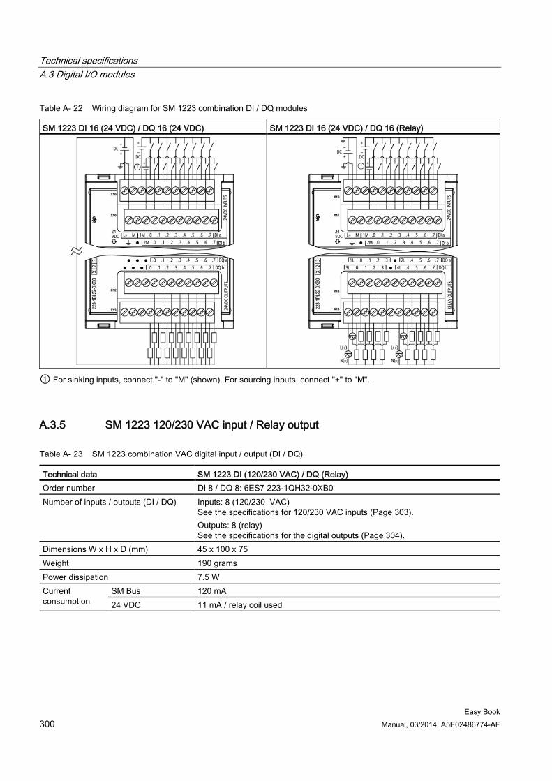
Technical specifications A.3 Digital I/O modules
Easy Book 300 Manual, 03/2014, A5E02486774-AF
Table A- 22 Wiring diagram for SM 1223 combination DI / DQ modules
SM 1223 DI 16 (24 VDC) / DQ 16 (24 VDC) SM 1223 DI 16 (24 VDC) / DQ 16 (Relay)
① For sinking inputs, connect "-" to "M" (shown). For sourcing inputs, connect "+" to "M".
A.3.5 SM 1223 120/230 VAC input / Relay output
Table A- 23 SM 1223 combination VAC digital input / output (DI / DQ)
Technical data SM 1223 DI (120/230 VAC) / DQ (Relay) Order number DI 8 / DQ 8: 6ES7 223-1QH32-0XB0 Number of inputs / outputs (DI / DQ) Inputs: 8 (120/230 VAC)
See the specifications for 120/230 VAC inputs (Page 303). Outputs: 8 (relay) See the specifications for the digital outputs (Page 304).
Dimensions W x H x D (mm) 45 x 100 x 75 Weight 190 grams Power dissipation 7.5 W Current consumption
SM Bus 120 mA 24 VDC 11 mA / relay coil used
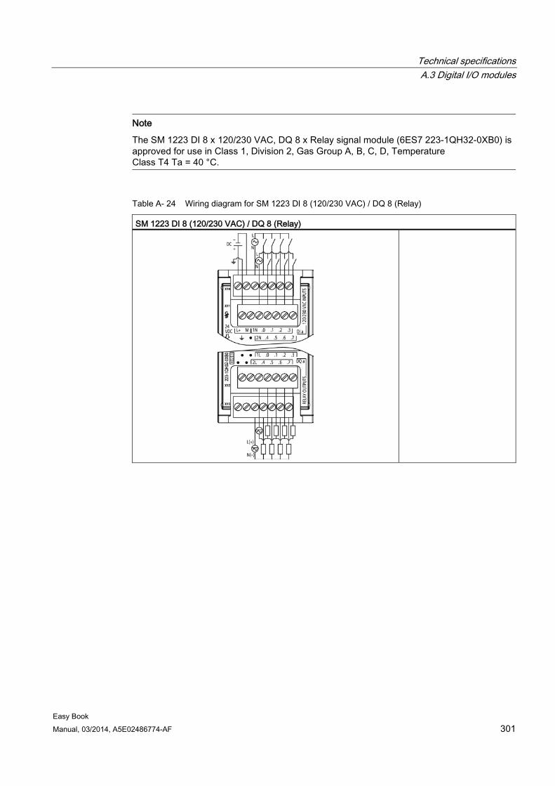
Technical specifications A.3 Digital I/O modules
Easy Book Manual, 03/2014, A5E02486774-AF 301
Note
The SM 1223 DI 8 x 120/230 VAC, DQ 8 x Relay signal module (6ES7 223-1QH32-0XB0) is approved for use in Class 1, Division 2, Gas Group A, B, C, D, Temperature Class T4 Ta = 40 °C.
Table A- 24 Wiring diagram for SM 1223 DI 8 (120/230 VAC) / DQ 8 (Relay)
SM 1223 DI 8 (120/230 VAC) / DQ 8 (Relay)
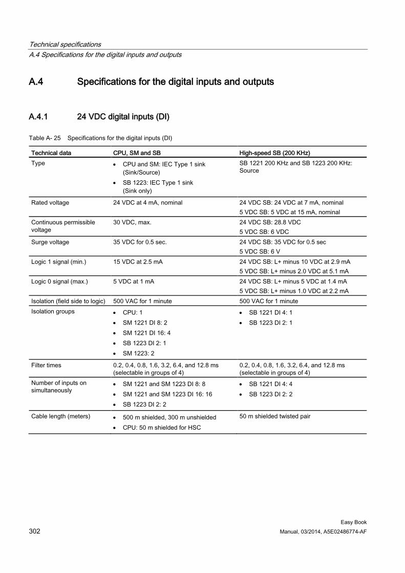
Technical specifications A.4 Specifications for the digital inputs and outputs
Easy Book 302 Manual, 03/2014, A5E02486774-AF
A.4 Specifications for the digital inputs and outputs
A.4.1 24 VDC digital inputs (DI)
Table A- 25 Specifications for the digital inputs (DI)
Technical data CPU, SM and SB High-speed SB (200 KHz) Type • CPU and SM: IEC Type 1 sink
(Sink/Source) • SB 1223: IEC Type 1 sink
(Sink only)
SB 1221 200 KHz and SB 1223 200 KHz: Source
Rated voltage 24 VDC at 4 mA, nominal 24 VDC SB: 24 VDC at 7 mA, nominal 5 VDC SB: 5 VDC at 15 mA, nominal
Continuous permissible voltage
30 VDC, max. 24 VDC SB: 28.8 VDC 5 VDC SB: 6 VDC
Surge voltage 35 VDC for 0.5 sec. 24 VDC SB: 35 VDC for 0.5 sec 5 VDC SB: 6 V
Logic 1 signal (min.) 15 VDC at 2.5 mA 24 VDC SB: L+ minus 10 VDC at 2.9 mA 5 VDC SB: L+ minus 2.0 VDC at 5.1 mA
Logic 0 signal (max.) 5 VDC at 1 mA 24 VDC SB: L+ minus 5 VDC at 1.4 mA 5 VDC SB: L+ minus 1.0 VDC at 2.2 mA
Isolation (field side to logic) 500 VAC for 1 minute 500 VAC for 1 minute Isolation groups • CPU: 1
• SM 1221 DI 8: 2 • SM 1221 DI 16: 4 • SB 1223 DI 2: 1 • SM 1223: 2
• SB 1221 DI 4: 1 • SB 1223 DI 2: 1
Filter times 0.2, 0.4, 0.8, 1.6, 3.2, 6.4, and 12.8 ms (selectable in groups of 4)
0.2, 0.4, 0.8, 1.6, 3.2, 6.4, and 12.8 ms (selectable in groups of 4)
Number of inputs on simultaneously
• SM 1221 and SM 1223 DI 8: 8 • SM 1221 and SM 1223 DI 16: 16 • SB 1223 DI 2: 2
• SB 1221 DI 4: 4 • SB 1223 DI 2: 2
Cable length (meters) • 500 m shielded, 300 m unshielded • CPU: 50 m shielded for HSC
50 m shielded twisted pair
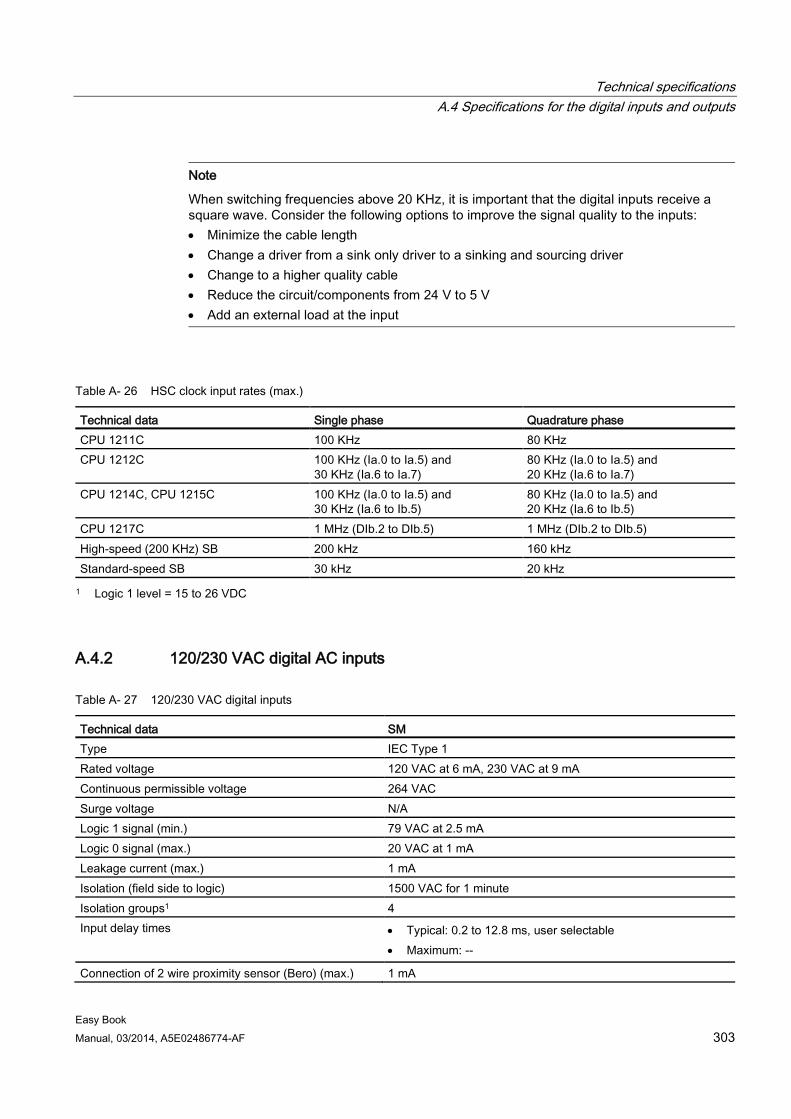
Technical specifications A.4 Specifications for the digital inputs and outputs
Easy Book Manual, 03/2014, A5E02486774-AF 303
Note
When switching frequencies above 20 KHz, it is important that the digital inputs receive a square wave. Consider the following options to improve the signal quality to the inputs: • Minimize the cable length • Change a driver from a sink only driver to a sinking and sourcing driver • Change to a higher quality cable • Reduce the circuit/components from 24 V to 5 V • Add an external load at the input
Table A- 26 HSC clock input rates (max.)
Technical data Single phase Quadrature phase CPU 1211C 100 KHz 80 KHz CPU 1212C 100 KHz (Ia.0 to Ia.5) and
30 KHz (Ia.6 to Ia.7) 80 KHz (Ia.0 to Ia.5) and 20 KHz (Ia.6 to Ia.7)
CPU 1214C, CPU 1215C 100 KHz (Ia.0 to Ia.5) and 30 KHz (Ia.6 to Ib.5)
80 KHz (Ia.0 to Ia.5) and 20 KHz (Ia.6 to Ib.5)
CPU 1217C 1 MHz (DIb.2 to DIb.5) 1 MHz (DIb.2 to DIb.5) High-speed (200 KHz) SB 200 kHz 160 kHz Standard-speed SB 30 kHz 20 kHz 1 Logic 1 level = 15 to 26 VDC
A.4.2 120/230 VAC digital AC inputs
Table A- 27 120/230 VAC digital inputs
Technical data SM Type IEC Type 1 Rated voltage 120 VAC at 6 mA, 230 VAC at 9 mA Continuous permissible voltage 264 VAC Surge voltage N/A Logic 1 signal (min.) 79 VAC at 2.5 mA Logic 0 signal (max.) 20 VAC at 1 mA Leakage current (max.) 1 mA Isolation (field side to logic) 1500 VAC for 1 minute Isolation groups1 4 Input delay times • Typical: 0.2 to 12.8 ms, user selectable
• Maximum: --
Connection of 2 wire proximity sensor (Bero) (max.) 1 mA
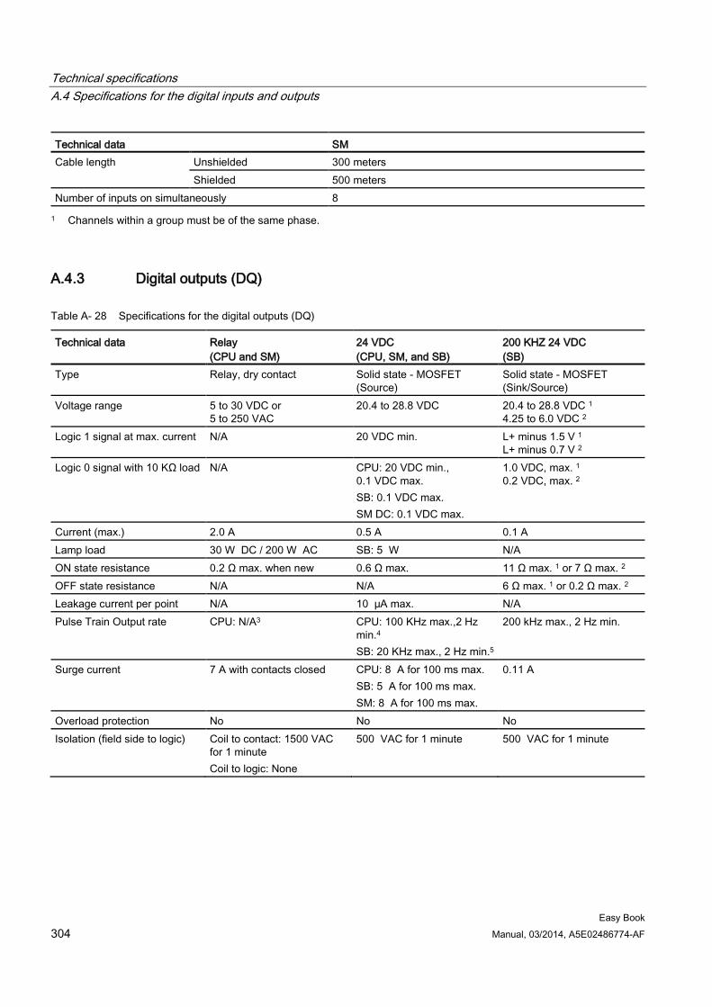
Technical specifications A.4 Specifications for the digital inputs and outputs
Easy Book 304 Manual, 03/2014, A5E02486774-AF
Technical data SM Cable length Unshielded 300 meters
Shielded 500 meters Number of inputs on simultaneously 8 1 Channels within a group must be of the same phase.
A.4.3 Digital outputs (DQ)
Table A- 28 Specifications for the digital outputs (DQ)
Technical data Relay (CPU and SM)
24 VDC (CPU, SM, and SB)
200 KHZ 24 VDC (SB)
Type Relay, dry contact Solid state - MOSFET (Source)
Solid state - MOSFET (Sink/Source)
Voltage range 5 to 30 VDC or 5 to 250 VAC
20.4 to 28.8 VDC 20.4 to 28.8 VDC 1 4.25 to 6.0 VDC 2
Logic 1 signal at max. current N/A 20 VDC min. L+ minus 1.5 V 1 L+ minus 0.7 V 2
Logic 0 signal with 10 KΩ load N/A CPU: 20 VDC min., 0.1 VDC max. SB: 0.1 VDC max. SM DC: 0.1 VDC max.
1.0 VDC, max. 1 0.2 VDC, max. 2
Current (max.) 2.0 A 0.5 A 0.1 A Lamp load 30 W DC / 200 W AC SB: 5 W N/A ON state resistance 0.2 Ω max. when new 0.6 Ω max. 11 Ω max. 1 or 7 Ω max. 2 OFF state resistance N/A N/A 6 Ω max. 1 or 0.2 Ω max. 2 Leakage current per point N/A 10 μA max. N/A Pulse Train Output rate CPU: N/A3 CPU: 100 KHz max.,2 Hz
min.4 SB: 20 KHz max., 2 Hz min.5
200 kHz max., 2 Hz min.
Surge current 7 A with contacts closed CPU: 8 A for 100 ms max. SB: 5 A for 100 ms max. SM: 8 A for 100 ms max.
0.11 A
Overload protection No No No Isolation (field side to logic) Coil to contact: 1500 VAC
for 1 minute Coil to logic: None
500 VAC for 1 minute 500 VAC for 1 minute
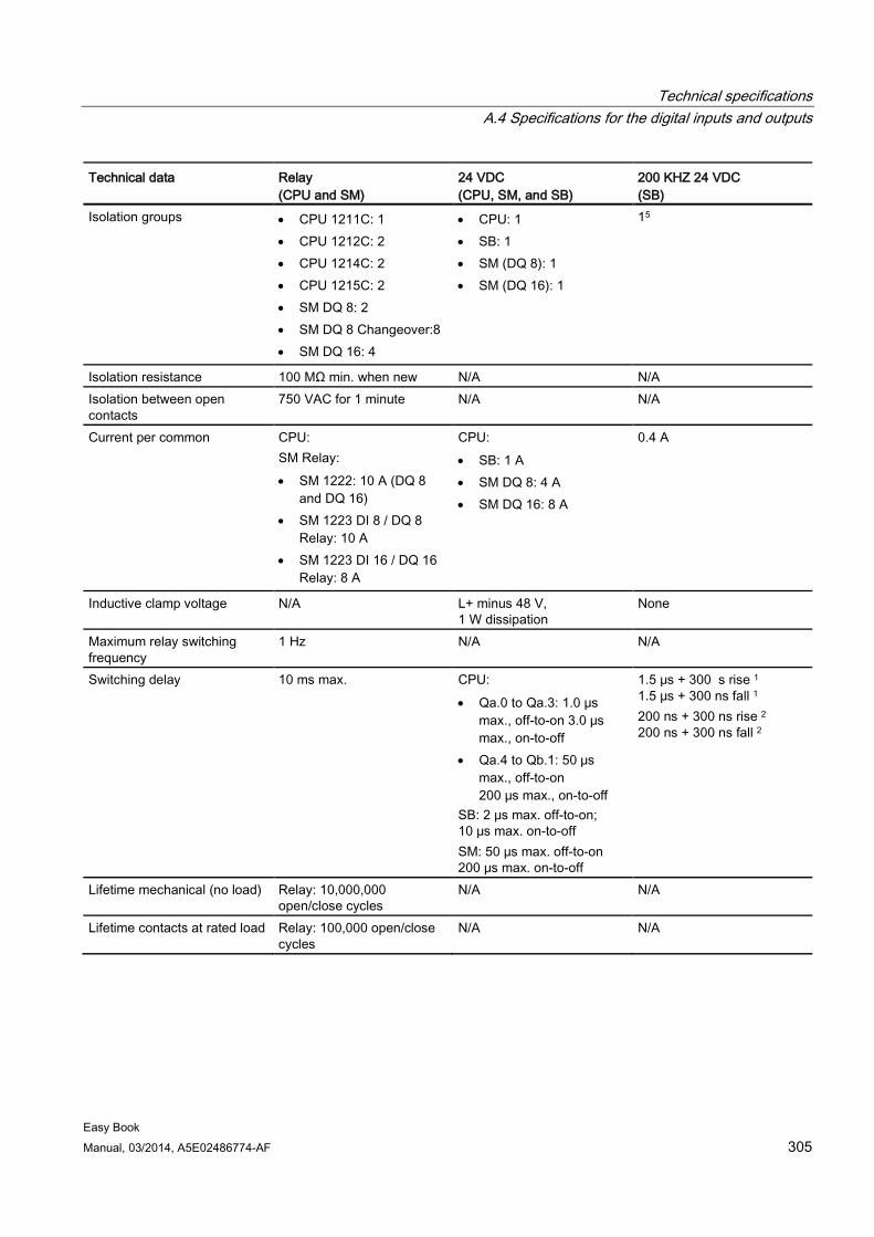
Technical specifications A.4 Specifications for the digital inputs and outputs
Easy Book Manual, 03/2014, A5E02486774-AF 305
Technical data Relay (CPU and SM)
24 VDC (CPU, SM, and SB)
200 KHZ 24 VDC (SB)
Isolation groups • CPU 1211C: 1 • CPU 1212C: 2 • CPU 1214C: 2 • CPU 1215C: 2 • SM DQ 8: 2 • SM DQ 8 Changeover:8 • SM DQ 16: 4
• CPU: 1 • SB: 1 • SM (DQ 8): 1 • SM (DQ 16): 1
15
Isolation resistance 100 MΩ min. when new N/A N/A Isolation between open contacts
750 VAC for 1 minute N/A N/A
Current per common CPU: SM Relay: • SM 1222: 10 A (DQ 8
and DQ 16) • SM 1223 DI 8 / DQ 8
Relay: 10 A • SM 1223 DI 16 / DQ 16
Relay: 8 A
CPU: • SB: 1 A • SM DQ 8: 4 A • SM DQ 16: 8 A
0.4 A
Inductive clamp voltage N/A L+ minus 48 V, 1 W dissipation
None
Maximum relay switching frequency
1 Hz N/A N/A
Switching delay 10 ms max. CPU: • Qa.0 to Qa.3: 1.0 μs
max., off-to-on 3.0 μs max., on-to-off
• Qa.4 to Qb.1: 50 μs max., off-to-on 200 μs max., on-to-off
SB: 2 μs max. off-to-on; 10 μs max. on-to-off SM: 50 μs max. off-to-on 200 μs max. on-to-off
1.5 μs + 300 s rise 1 1.5 μs + 300 ns fall 1 200 ns + 300 ns rise 2 200 ns + 300 ns fall 2
Lifetime mechanical (no load) Relay: 10,000,000 open/close cycles
N/A N/A
Lifetime contacts at rated load Relay: 100,000 open/close cycles
N/A N/A
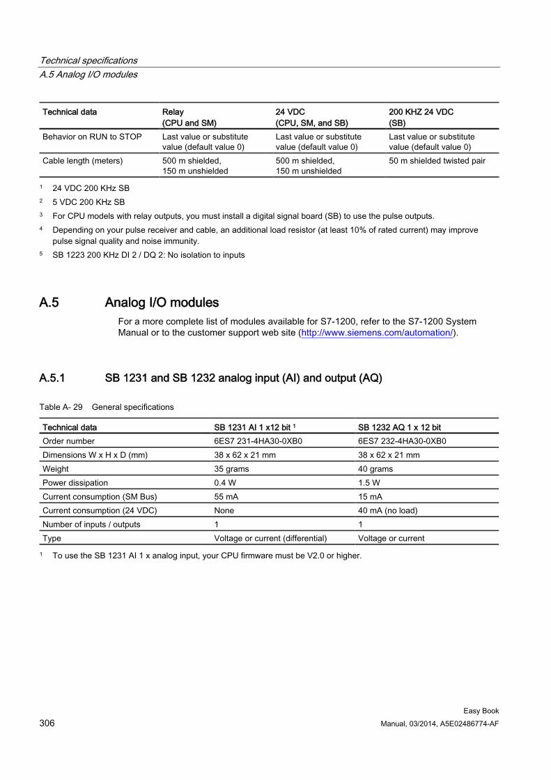
Technical specifications A.5 Analog I/O modules
Easy Book 306 Manual, 03/2014, A5E02486774-AF
Technical data Relay (CPU and SM)
24 VDC (CPU, SM, and SB)
200 KHZ 24 VDC (SB)
Behavior on RUN to STOP Last value or substitute value (default value 0)
Last value or substitute value (default value 0)
Last value or substitute value (default value 0)
Cable length (meters) 500 m shielded, 150 m unshielded
500 m shielded, 150 m unshielded
50 m shielded twisted pair
1 24 VDC 200 KHz SB 2 5 VDC 200 KHz SB 3 For CPU models with relay outputs, you must install a digital signal board (SB) to use the pulse outputs. 4 Depending on your pulse receiver and cable, an additional load resistor (at least 10% of rated current) may improve
pulse signal quality and noise immunity. 5 SB 1223 200 KHz DI 2 / DQ 2: No isolation to inputs
A.5 Analog I/O modules For a more complete list of modules available for S7-1200, refer to the S7-1200 System Manual or to the customer support web site (http://www.siemens.com/automation/).
A.5.1 SB 1231 and SB 1232 analog input (AI) and output (AQ)
Table A- 29 General specifications
Technical data SB 1231 AI 1 x12 bit 1 SB 1232 AQ 1 x 12 bit Order number 6ES7 231-4HA30-0XB0 6ES7 232-4HA30-0XB0 Dimensions W x H x D (mm) 38 x 62 x 21 mm 38 x 62 x 21 mm Weight 35 grams 40 grams Power dissipation 0.4 W 1.5 W Current consumption (SM Bus) 55 mA 15 mA Current consumption (24 VDC) None 40 mA (no load) Number of inputs / outputs 1 1 Type Voltage or current (differential) Voltage or current 1 To use the SB 1231 AI 1 x analog input, your CPU firmware must be V2.0 or higher.
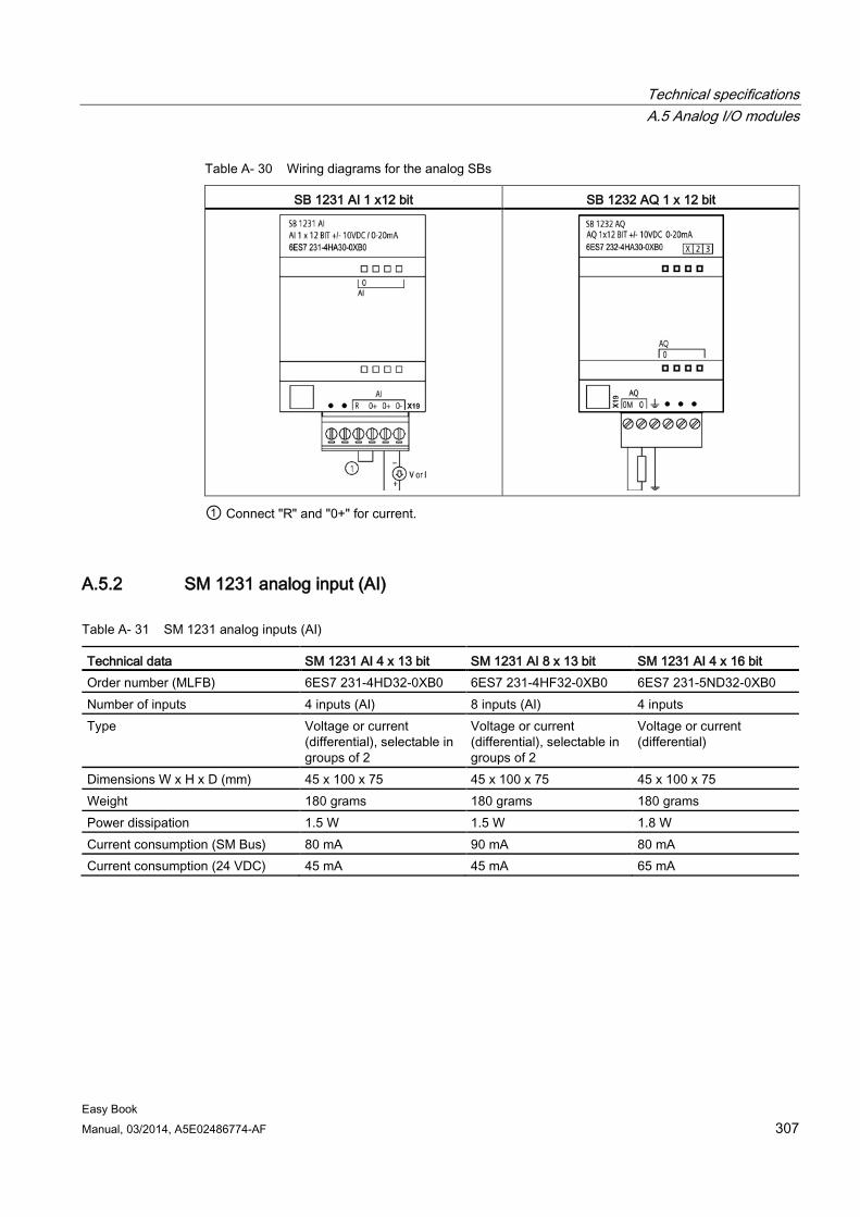
Technical specifications A.5 Analog I/O modules
Easy Book Manual, 03/2014, A5E02486774-AF 307
Table A- 30 Wiring diagrams for the analog SBs
SB 1231 AI 1 x12 bit SB 1232 AQ 1 x 12 bit
① Connect "R" and "0+" for current.
A.5.2 SM 1231 analog input (AI)
Table A- 31 SM 1231 analog inputs (AI)
Technical data SM 1231 AI 4 x 13 bit SM 1231 AI 8 x 13 bit SM 1231 AI 4 x 16 bit Order number (MLFB) 6ES7 231-4HD32-0XB0 6ES7 231-4HF32-0XB0 6ES7 231-5ND32-0XB0 Number of inputs 4 inputs (AI) 8 inputs (AI) 4 inputs Type Voltage or current
(differential), selectable in groups of 2
Voltage or current (differential), selectable in groups of 2
Voltage or current (differential)
Dimensions W x H x D (mm) 45 x 100 x 75 45 x 100 x 75 45 x 100 x 75 Weight 180 grams 180 grams 180 grams Power dissipation 1.5 W 1.5 W 1.8 W Current consumption (SM Bus) 80 mA 90 mA 80 mA Current consumption (24 VDC) 45 mA 45 mA 65 mA
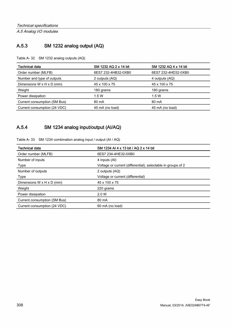
Technical specifications A.5 Analog I/O modules
Easy Book 308 Manual, 03/2014, A5E02486774-AF
A.5.3 SM 1232 analog output (AQ)
Table A- 32 SM 1232 analog outputs (AQ)
Technical data SM 1232 AQ 2 x 14 bit SM 1232 AQ 4 x 14 bit Order number (MLFB) 6ES7 232-4HB32-0XB0 6ES7 232-4HD32-0XB0 Number and type of outputs 2 outputs (AQ) 4 outputs (AQ) Dimensions W x H x D (mm) 45 x 100 x 75 45 x 100 x 75 Weight 180 grams 180 grams Power dissipation 1.5 W 1.5 W Current consumption (SM Bus) 80 mA 80 mA Current consumption (24 VDC) 45 mA (no load) 45 mA (no load)
A.5.4 SM 1234 analog input/output (AI/AQ)
Table A- 33 SM 1234 combination analog input / output (AI / AQ)
Technical data SM 1234 AI 4 x 13 bit / AQ 2 x 14 bit Order number (MLFB) 6ES7 234-4HE32-0XB0 Number of inputs Type
4 inputs (AI) Voltage or current (differential), selectable in groups of 2
Number of outputs Type
2 outputs (AQ) Voltage or current (differential)
Dimensions W x H x D (mm) 45 x 100 x 75 Weight 220 grams Power dissipation 2.0 W Current consumption (SM Bus) 80 mA Current consumption (24 VDC) 60 mA (no load)
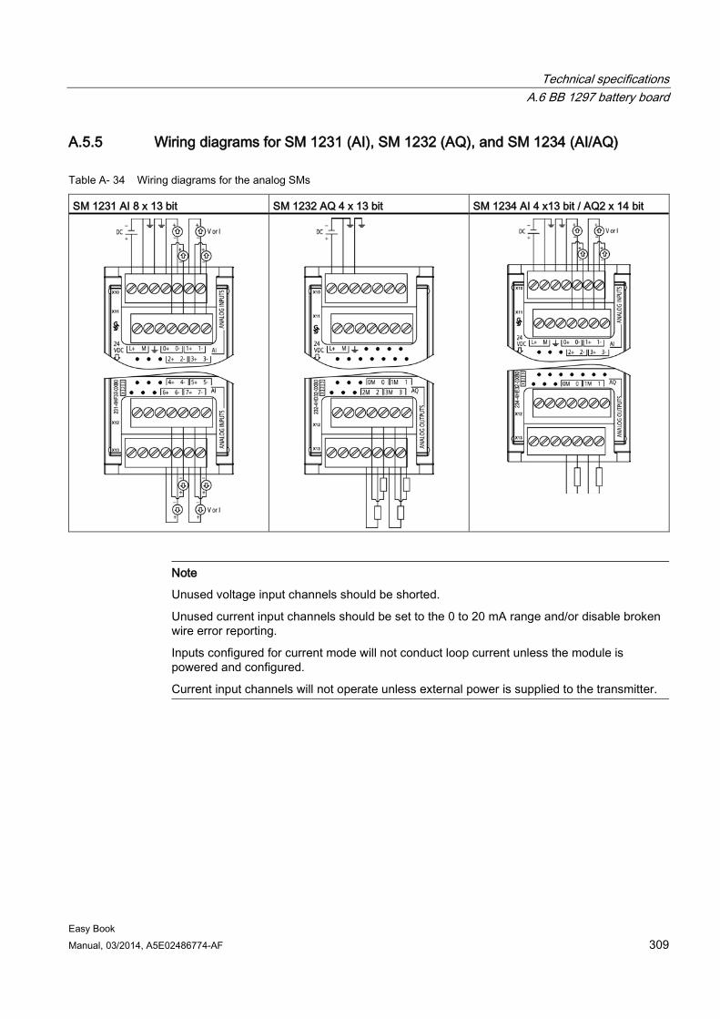
Technical specifications A.6 BB 1297 battery board
Easy Book Manual, 03/2014, A5E02486774-AF 309
A.5.5 Wiring diagrams for SM 1231 (AI), SM 1232 (AQ), and SM 1234 (AI/AQ)
Table A- 34 Wiring diagrams for the analog SMs
SM 1231 AI 8 x 13 bit SM 1232 AQ 4 x 13 bit SM 1234 AI 4 x13 bit / AQ2 x 14 bit
Note
Unused voltage input channels should be shorted.
Unused current input channels should be set to the 0 to 20 mA range and/or disable broken wire error reporting.
Inputs configured for current mode will not conduct loop current unless the module is powered and configured.
Current input channels will not operate unless external power is supplied to the transmitter.
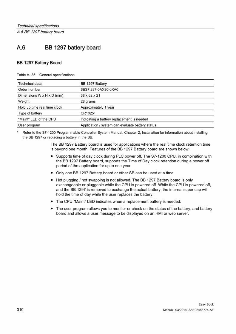
Technical specifications A.6 BB 1297 battery board
Easy Book 310 Manual, 03/2014, A5E02486774-AF
A.6 BB 1297 battery board
BB 1297 Battery Board
Table A- 35 General specifications
Technical data BB 1297 Battery Order number 6ES7 297-0AX30-0XA0 Dimensions W x H x D (mm) 38 x 62 x 21 Weight 28 grams Hold up time real time clock Approximately 1 year Type of battery CR10251 "Maint" LED of the CPU Indicating a battery replacement is needed User program Application / system can evaluate battery status 1 Refer to the S7-1200 Programmable Controller System Manual, Chapter 2, Installation for information about installing
the BB 1297 or replacing a battery in the BB.
The BB 1297 Battery board is used for applications where the real time clock retention time is beyond one month. Features of the BB 1297 Battery board are shown below:
● Supports time of day clock during PLC power off. The S7-1200 CPU, in combination with the BB 1297 Battery board, supports the Time of Day clock retention during a power off period of the application for up to one year.
● Only one BB 1297 Battery board or other SB can be used at a time.
● Hot plugging / hot swapping is not allowed. The BB 1297 Battery board is only exchangeable or pluggable while the CPU is powered off. While the CPU is powered off, and the BB 1297 is removed to exchange the actual battery, the internal super cap will hold the time of day while the user replaces the battery.
● The CPU "Maint" LED indicates when a replacement battery is needed.
● The user program allows you to monitor or check on the status of the battery, and battery board and allows a user message to be displayed on an HMI or web server.
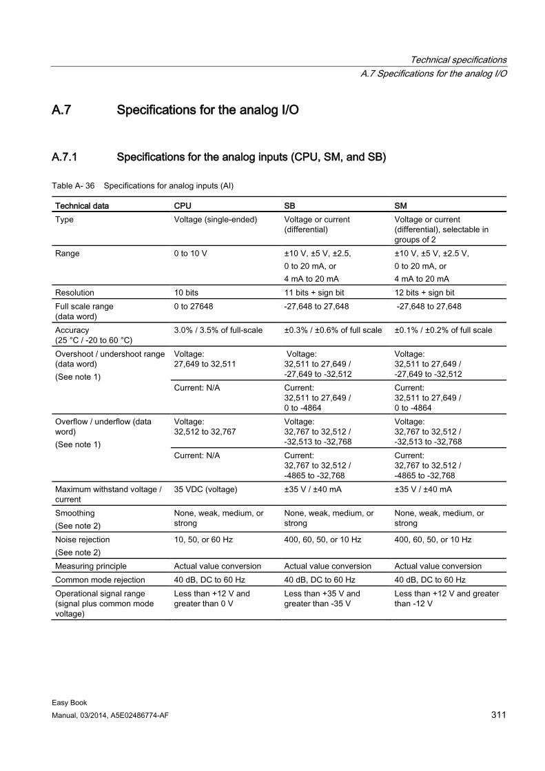
Technical specifications A.7 Specifications for the analog I/O
Easy Book Manual, 03/2014, A5E02486774-AF 311
A.7 Specifications for the analog I/O
A.7.1 Specifications for the analog inputs (CPU, SM, and SB)
Table A- 36 Specifications for analog inputs (AI)
Technical data CPU SB SM Type Voltage (single-ended) Voltage or current
(differential) Voltage or current (differential), selectable in groups of 2
Range 0 to 10 V ±10 V, ±5 V, ±2.5, 0 to 20 mA, or 4 mA to 20 mA
±10 V, ±5 V, ±2.5 V, 0 to 20 mA, or 4 mA to 20 mA
Resolution 10 bits 11 bits + sign bit 12 bits + sign bit Full scale range (data word)
0 to 27648 -27,648 to 27,648 -27,648 to 27,648
Accuracy (25 °C / -20 to 60 °C)
3.0% / 3.5% of full-scale ±0.3% / ±0.6% of full scale ±0.1% / ±0.2% of full scale
Overshoot / undershoot range (data word) (See note 1)
Voltage: 27,649 to 32,511
Voltage: 32,511 to 27,649 / -27,649 to -32,512
Voltage: 32,511 to 27,649 / -27,649 to -32,512
Current: N/A Current: 32,511 to 27,649 / 0 to -4864
Current: 32,511 to 27,649 / 0 to -4864
Overflow / underflow (data word) (See note 1)
Voltage: 32,512 to 32,767
Voltage: 32,767 to 32,512 / -32,513 to -32,768
Voltage: 32,767 to 32,512 / -32,513 to -32,768
Current: N/A Current: 32,767 to 32,512 / -4865 to -32,768
Current: 32,767 to 32,512 / -4865 to -32,768
Maximum withstand voltage / current
35 VDC (voltage) ±35 V / ±40 mA ±35 V / ±40 mA
Smoothing (See note 2)
None, weak, medium, or strong
None, weak, medium, or strong
None, weak, medium, or strong
Noise rejection (See note 2)
10, 50, or 60 Hz 400, 60, 50, or 10 Hz 400, 60, 50, or 10 Hz
Measuring principle Actual value conversion Actual value conversion Actual value conversion Common mode rejection 40 dB, DC to 60 Hz 40 dB, DC to 60 Hz 40 dB, DC to 60 Hz Operational signal range (signal plus common mode voltage)
Less than +12 V and greater than 0 V
Less than +35 V and greater than -35 V
Less than +12 V and greater than -12 V
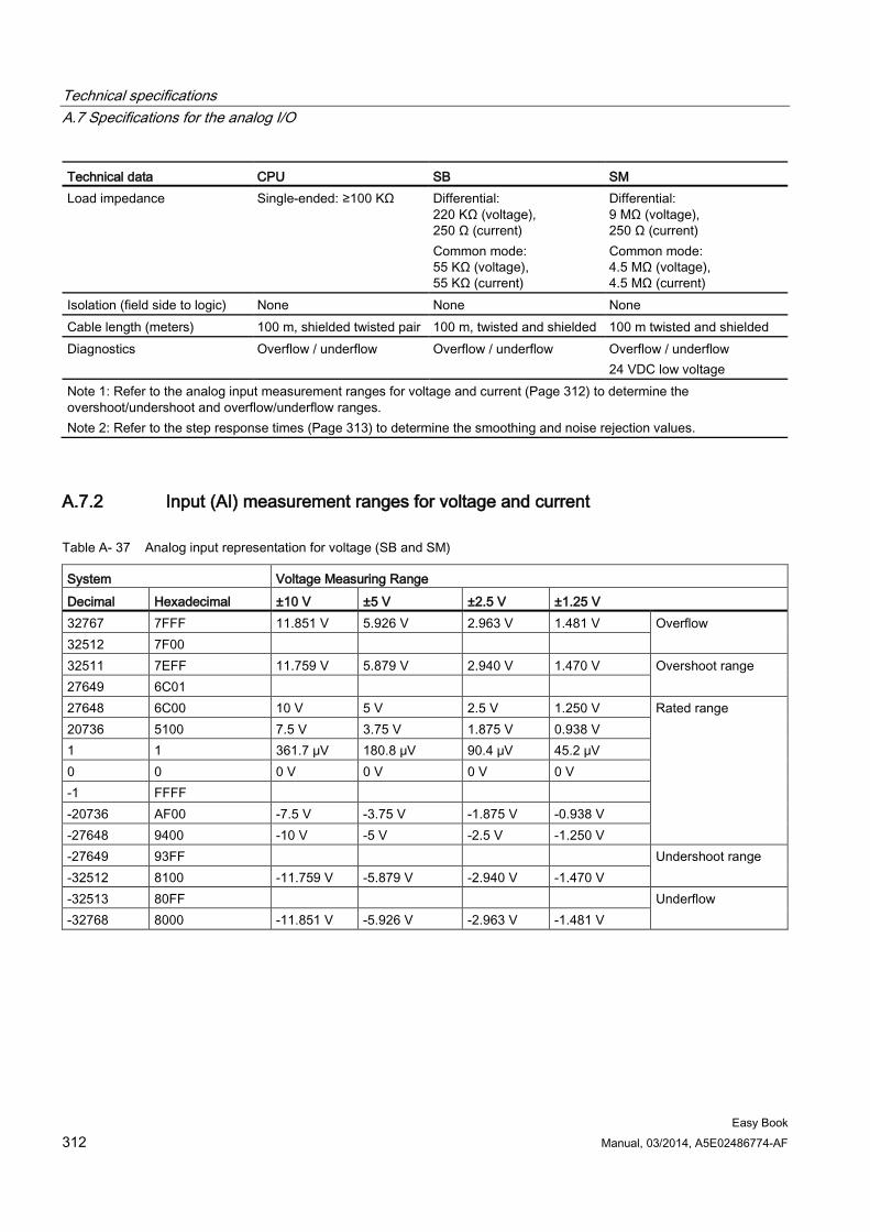
Technical specifications A.7 Specifications for the analog I/O
Easy Book 312 Manual, 03/2014, A5E02486774-AF
Technical data CPU SB SM Load impedance Single-ended: ≥100 KΩ Differential:
220 KΩ (voltage), 250 Ω (current) Common mode: 55 KΩ (voltage), 55 KΩ (current)
Differential: 9 MΩ (voltage), 250 Ω (current) Common mode: 4.5 MΩ (voltage), 4.5 MΩ (current)
Isolation (field side to logic) None None None Cable length (meters) 100 m, shielded twisted pair 100 m, twisted and shielded 100 m twisted and shielded Diagnostics Overflow / underflow Overflow / underflow Overflow / underflow
24 VDC low voltage Note 1: Refer to the analog input measurement ranges for voltage and current (Page 312) to determine the overshoot/undershoot and overflow/underflow ranges. Note 2: Refer to the step response times (Page 313) to determine the smoothing and noise rejection values.
A.7.2 Input (AI) measurement ranges for voltage and current
Table A- 37 Analog input representation for voltage (SB and SM)
System Voltage Measuring Range Decimal Hexadecimal ±10 V ±5 V ±2.5 V ±1.25 V 32767 7FFF 11.851 V 5.926 V 2.963 V 1.481 V Overflow 32512 7F00 32511 7EFF 11.759 V 5.879 V 2.940 V 1.470 V Overshoot range 27649 6C01 27648 6C00 10 V 5 V 2.5 V 1.250 V Rated range 20736 5100 7.5 V 3.75 V 1.875 V 0.938 V 1 1 361.7 μV 180.8 μV 90.4 μV 45.2 μV 0 0 0 V 0 V 0 V 0 V -1 FFFF -20736 AF00 -7.5 V -3.75 V -1.875 V -0.938 V -27648 9400 -10 V -5 V -2.5 V -1.250 V -27649 93FF Undershoot range -32512 8100 -11.759 V -5.879 V -2.940 V -1.470 V -32513 80FF Underflow -32768 8000 -11.851 V -5.926 V -2.963 V -1.481 V
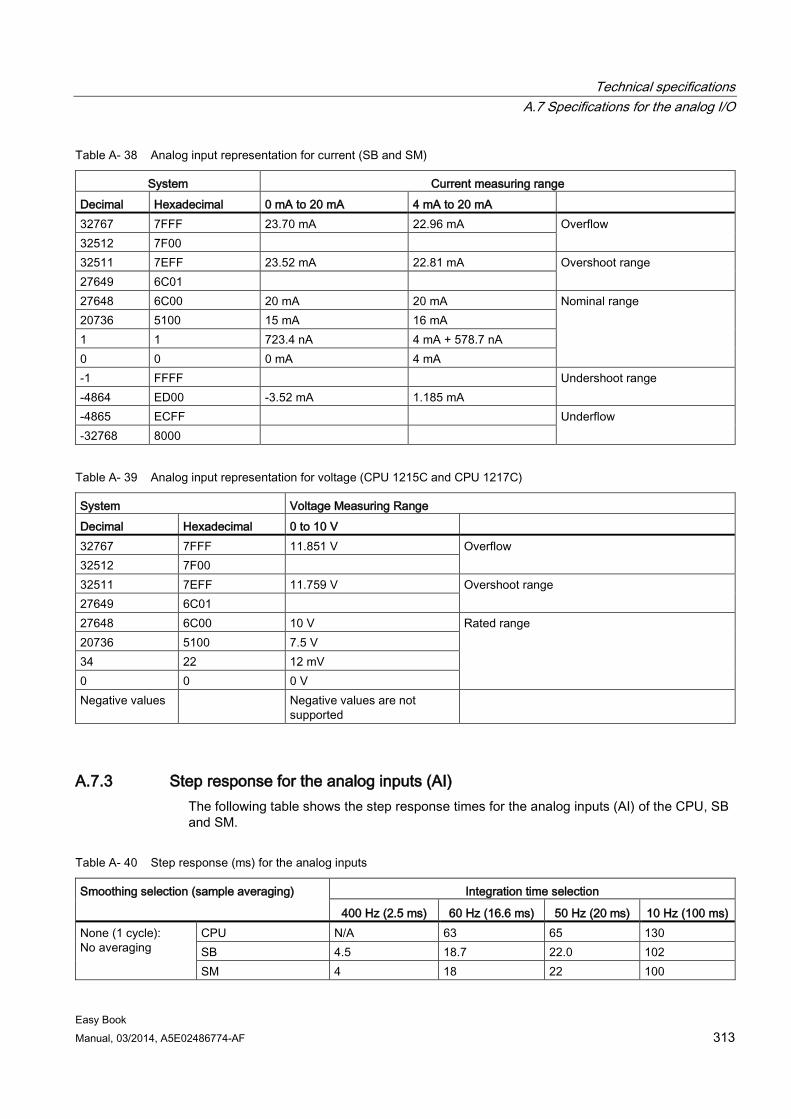
Technical specifications A.7 Specifications for the analog I/O
Easy Book Manual, 03/2014, A5E02486774-AF 313
Table A- 38 Analog input representation for current (SB and SM)
System Current measuring range Decimal Hexadecimal 0 mA to 20 mA 4 mA to 20 mA 32767 7FFF 23.70 mA 22.96 mA Overflow 32512 7F00 32511 7EFF 23.52 mA 22.81 mA Overshoot range 27649 6C01 27648 6C00 20 mA 20 mA Nominal range 20736 5100 15 mA 16 mA 1 1 723.4 nA 4 mA + 578.7 nA 0 0 0 mA 4 mA -1 FFFF Undershoot range -4864 ED00 -3.52 mA 1.185 mA -4865 ECFF Underflow -32768 8000
Table A- 39 Analog input representation for voltage (CPU 1215C and CPU 1217C)
System Voltage Measuring Range Decimal Hexadecimal 0 to 10 V 32767 7FFF 11.851 V Overflow 32512 7F00 32511 7EFF 11.759 V Overshoot range 27649 6C01 27648 6C00 10 V Rated range 20736 5100 7.5 V 34 22 12 mV 0 0 0 V Negative values Negative values are not
supported
A.7.3 Step response for the analog inputs (AI) The following table shows the step response times for the analog inputs (AI) of the CPU, SB and SM.
Table A- 40 Step response (ms) for the analog inputs
Smoothing selection (sample averaging) Integration time selection
400 Hz (2.5 ms) 60 Hz (16.6 ms) 50 Hz (20 ms) 10 Hz (100 ms) None (1 cycle): No averaging
CPU N/A 63 65 130 SB 4.5 18.7 22.0 102 SM 4 18 22 100
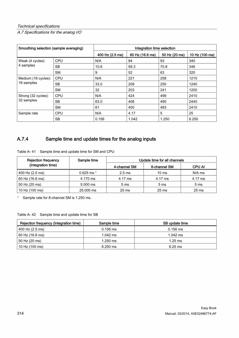
Technical specifications A.7 Specifications for the analog I/O
Easy Book 314 Manual, 03/2014, A5E02486774-AF
Smoothing selection (sample averaging) Integration time selection
400 Hz (2.5 ms) 60 Hz (16.6 ms) 50 Hz (20 ms) 10 Hz (100 ms) Weak (4 cycles): 4 samples
CPU N/A 84 93 340 SB 10.6 59.3 70.8 346 SM 9 52 63 320
Medium (16 cycles): 16 samples
CPU N/A 221 258 1210 SB 33.0 208 250 1240 SM 32 203 241 1200
Strong (32 cycles): 32 samples
CPU N/A 424 499 2410 SB 63.0 408 490 2440 SM 61 400 483 2410
Sample rate CPU N/A 4.17 5 25 SB 0.156 1.042 1.250 6.250
A.7.4 Sample time and update times for the analog inputs
Table A- 41 Sample time and update time for SM and CPU
Rejection frequency (Integration time)
Sample time Update time for all channels
4-channel SM 8-channel SM CPU AI 400 Hz (2.5 ms) 0.625 ms 1 2.5 ms 10 ms N/A ms 60 Hz (16.6 ms) 4.170 ms 4.17 ms 4.17 ms 4.17 ms 50 Hz (20 ms) 5.000 ms 5 ms 5 ms 5 ms 10 Hz (100 ms) 25.000 ms 25 ms 25 ms 25 ms 1 Sample rate for 8-channel SM is 1.250 ms.
Table A- 42 Sample time and update time for SB
Rejection frequency (Integration time) Sample time SB update time 400 Hz (2.5 ms) 0.156 ms 0.156 ms 60 Hz (16.6 ms) 1.042 ms 1.042 ms 50 Hz (20 ms) 1.250 ms 1.25 ms 10 Hz (100 ms) 6.250 ms 6.25 ms
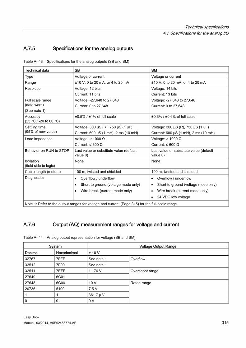
Technical specifications A.7 Specifications for the analog I/O
Easy Book Manual, 03/2014, A5E02486774-AF 315
A.7.5 Specifications for the analog outputs
Table A- 43 Specifications for the analog outputs (SB and SM)
Technical data SB SM Type Voltage or current Voltage or current Range ±10 V, 0 to 20 mA, or 4 to 20 mA ±10 V, 0 to 20 mA, or 4 to 20 mA Resolution Voltage: 12 bits
Current: 11 bits Voltage: 14 bits Current: 13 bits
Full scale range (data word) (See note 1)
Voltage: -27,648 to 27,648 Current: 0 to 27,648
Voltage: -27,648 to 27,648 Current: 0 to 27,648
Accuracy (25 °C / -20 to 60 °C)
±0.5% / ±1% of full scale ±0.3% / ±0.6% of full scale
Settling time (95% of new value)
Voltage: 300 μS (R), 750 μS (1 uF) Current: 600 μS (1 mH), 2 ms (10 mH)
Voltage: 300 μS (R), 750 μS (1 uF) Current: 600 μS (1 mH), 2 ms (10 mH)
Load impedance Voltage: ≥ 1000 Ω Current: ≤ 600 Ω
Voltage: ≥ 1000 Ω Current: ≤ 600 Ω
Behavior on RUN to STOP Last value or substitute value (default value 0)
Last value or substitute value (default value 0)
Isolation (field side to logic)
None None
Cable length (meters) 100 m, twisted and shielded 100 m, twisted and shielded Diagnostics • Overflow / underflow
• Short to ground (voltage mode only) • Wire break (current mode only)
• Overflow / underflow • Short to ground (voltage mode only) • Wire break (current mode only) • 24 VDC low voltage
Note 1: Refer to the output ranges for voltage and current (Page 315) for the full-scale range.
A.7.6 Output (AQ) measurement ranges for voltage and current
Table A- 44 Analog output representation for voltage (SB and SM)
System Voltage Output Range Decimal Hexadecimal ± 10 V 32767 7FFF See note 1 Overflow 32512 7F00 See note 1 32511 7EFF 11.76 V Overshoot range 27649 6C01 27648 6C00 10 V Rated range 20736 5100 7.5 V 1 1 361.7 μ V 0 0 0 V
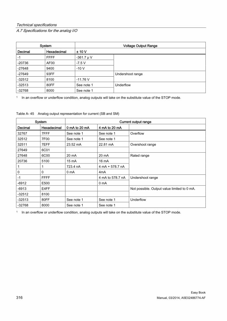
Technical specifications A.7 Specifications for the analog I/O
Easy Book 316 Manual, 03/2014, A5E02486774-AF
System Voltage Output Range Decimal Hexadecimal ± 10 V -1 FFFF -361.7 μ V -20736 AF00 -7.5 V -27648 9400 -10 V -27649 93FF Undershoot range -32512 8100 -11.76 V -32513 80FF See note 1 Underflow -32768 8000 See note 1 1 In an overflow or underflow condition, analog outputs will take on the substitute value of the STOP mode.
Table A- 45 Analog output representation for current (SB and SM)
System Current output range Decimal Hexadecimal 0 mA to 20 mA 4 mA to 20 mA 32767 7FFF See note 1 See note 1 Overflow 32512 7F00 See note 1 See note 1 32511 7EFF 23.52 mA 22.81 mA Overshoot range 27649 6C01 27648 6C00 20 mA 20 mA Rated range 20736 5100 15 mA 16 mA 1 1 723.4 nA 4 mA + 578.7 nA 0 0 0 mA 4mA -1 FFFF 4 mA to 578.7 nA Undershoot range -6912 E500 0 mA -6913 E4FF Not possible. Output value limited to 0 mA. -32512 8100 -32513 80FF See note 1 See note 1 Underflow -32768 8000 See note 1 See note 1 1 In an overflow or underflow condition, analog outputs will take on the substitute value of the STOP mode.
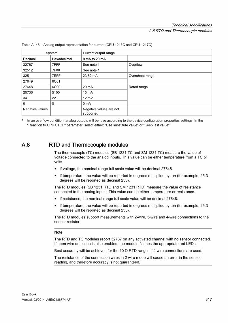
Technical specifications A.8 RTD and Thermocouple modules
Easy Book Manual, 03/2014, A5E02486774-AF 317
Table A- 46 Analog output representation for current (CPU 1215C and CPU 1217C)
System Current output range Decimal Hexadecimal 0 mA to 20 mA 32767 7FFF See note 1 Overflow
32512 7F00 See note 1 32511 7EFF 23.52 mA Overshoot range 27649 6C01 27648 6C00 20 mA Rated range 20736 5100 15 mA 34 22 12 mV 0 0 0 mA Negative values Negative values are not
supported
1 In an overflow condition, analog outputs will behave according to the device configuration properties settings. In the "Reaction to CPU STOP" parameter, select either: "Use substitute value" or "Keep last value".
A.8 RTD and Thermocouple modules The thermocouple (TC) modules (SB 1231 TC and SM 1231 TC) measure the value of voltage connected to the analog inputs. This value can be either temperature from a TC or volts.
● If voltage, the nominal range full scale value will be decimal 27648.
● If temperature, the value will be reported in degrees multiplied by ten (for example, 25.3 degrees will be reported as decimal 253).
The RTD modules (SB 1231 RTD and SM 1231 RTD) measure the value of resistance connected to the analog inputs. This value can be either temperature or resistance.
● If resistance, the nominal range full scale value will be decimal 27648.
● If temperature, the value will be reported in degrees multiplied by ten (for example, 25.3 degrees will be reported as decimal 253).
The RTD modules support measurements with 2-wire, 3-wire and 4-wire connections to the sensor resistor.
Note
The RTD and TC modules report 32767 on any activated channel with no sensor connected. If open wire detection is also enabled, the module flashes the appropriate red LEDs.
Best accuracy will be achieved for the 10 Ω RTD ranges if 4 wire connections are used.
The resistance of the connection wires in 2 wire mode will cause an error in the sensor reading, and therefore accuracy is not guaranteed.
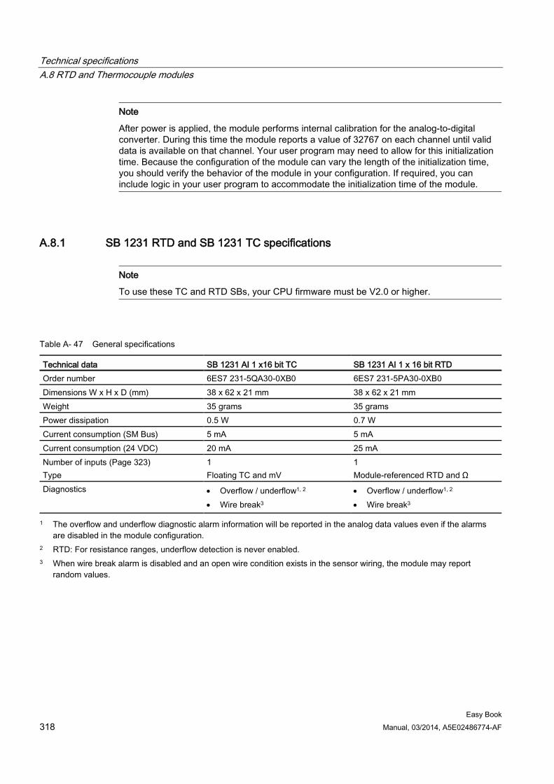
Technical specifications A.8 RTD and Thermocouple modules
Easy Book 318 Manual, 03/2014, A5E02486774-AF
Note
After power is applied, the module performs internal calibration for the analog-to-digital converter. During this time the module reports a value of 32767 on each channel until valid data is available on that channel. Your user program may need to allow for this initialization time. Because the configuration of the module can vary the length of the initialization time, you should verify the behavior of the module in your configuration. If required, you can include logic in your user program to accommodate the initialization time of the module.
A.8.1 SB 1231 RTD and SB 1231 TC specifications
Note
To use these TC and RTD SBs, your CPU firmware must be V2.0 or higher.
Table A- 47 General specifications
Technical data SB 1231 AI 1 x16 bit TC SB 1231 AI 1 x 16 bit RTD Order number 6ES7 231-5QA30-0XB0 6ES7 231-5PA30-0XB0 Dimensions W x H x D (mm) 38 x 62 x 21 mm 38 x 62 x 21 mm Weight 35 grams 35 grams Power dissipation 0.5 W 0.7 W Current consumption (SM Bus) 5 mA 5 mA Current consumption (24 VDC) 20 mA 25 mA Number of inputs (Page 323) Type
1 Floating TC and mV
1 Module-referenced RTD and Ω
Diagnostics • Overflow / underflow1, 2 • Wire break3
• Overflow / underflow1, 2 • Wire break3
1 The overflow and underflow diagnostic alarm information will be reported in the analog data values even if the alarms are disabled in the module configuration.
2 RTD: For resistance ranges, underflow detection is never enabled. 3 When wire break alarm is disabled and an open wire condition exists in the sensor wiring, the module may report
random values.
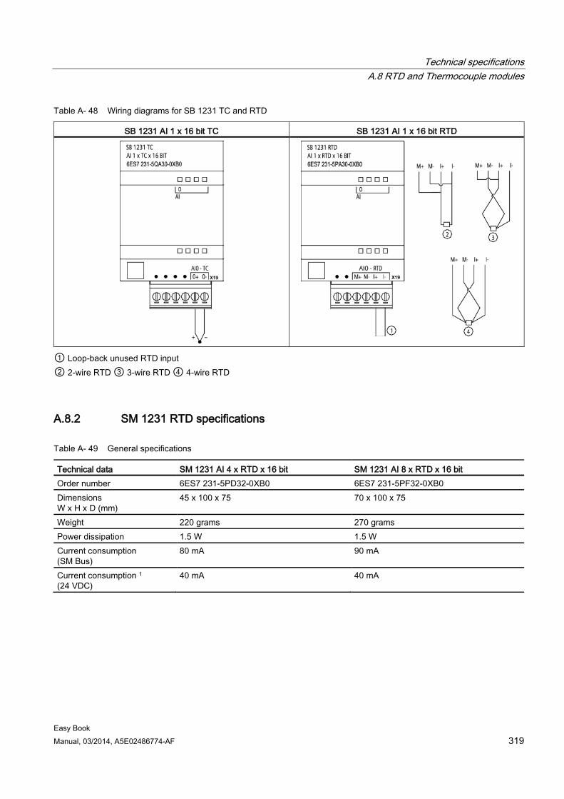
Technical specifications A.8 RTD and Thermocouple modules
Easy Book Manual, 03/2014, A5E02486774-AF 319
Table A- 48 Wiring diagrams for SB 1231 TC and RTD
SB 1231 AI 1 x 16 bit TC SB 1231 AI 1 x 16 bit RTD
① Loop-back unused RTD input ② 2-wire RTD ③ 3-wire RTD ④ 4-wire RTD
A.8.2 SM 1231 RTD specifications
Table A- 49 General specifications
Technical data SM 1231 AI 4 x RTD x 16 bit SM 1231 AI 8 x RTD x 16 bit Order number 6ES7 231-5PD32-0XB0 6ES7 231-5PF32-0XB0 Dimensions W x H x D (mm)
45 x 100 x 75 70 x 100 x 75
Weight 220 grams 270 grams Power dissipation 1.5 W 1.5 W Current consumption (SM Bus)
80 mA 90 mA
Current consumption 1 (24 VDC)
40 mA 40 mA
Technical specifications A.8 RTD and Thermocouple modules
Easy Book 320 Manual, 03/2014, A5E02486774-AF
Technical data SM 1231 AI 4 x RTD x 16 bit SM 1231 AI 8 x RTD x 16 bit Number of inputs (Page 323) Type
4 Module-referenced RTD and Ω
8 Module-referenced RTD and Ω
Diagnostics • Overflow / underflow 2,3 • 24 VDC low voltage 2 • Wire break (current mode only) 4
• Overflow / underflow 2,3 • 24 VDC low voltage 2 • Wire break (current mode only) 4
1 20.4 to 28.8 VDC (Class 2, Limited Power, or sensor power from CPU) 2 The overflow, underflow and low voltage diagnostic alarm information will be reported in the analog data values even if
the alarms are disabled in the module configuration. 3 For resistance ranges underflow detection is never enabled. 4 When wire break alarm is disabled and an open wire condition exists in the sensor wiring, the module may report
random values.
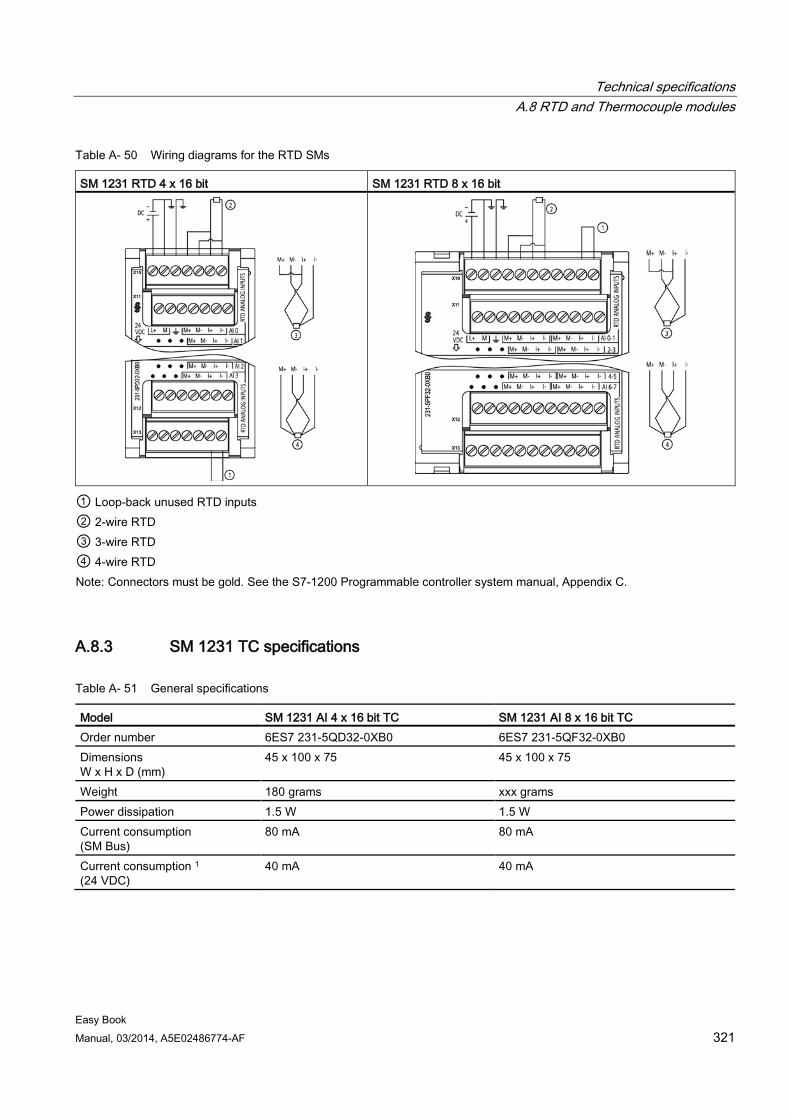
Technical specifications A.8 RTD and Thermocouple modules
Easy Book Manual, 03/2014, A5E02486774-AF 321
Table A- 50 Wiring diagrams for the RTD SMs
SM 1231 RTD 4 x 16 bit SM 1231 RTD 8 x 16 bit
① Loop-back unused RTD inputs ② 2-wire RTD ③ 3-wire RTD ④ 4-wire RTD Note: Connectors must be gold. See the S7-1200 Programmable controller system manual, Appendix C.
A.8.3 SM 1231 TC specifications
Table A- 51 General specifications
Model SM 1231 AI 4 x 16 bit TC SM 1231 AI 8 x 16 bit TC Order number 6ES7 231-5QD32-0XB0 6ES7 231-5QF32-0XB0 Dimensions W x H x D (mm)
45 x 100 x 75 45 x 100 x 75
Weight 180 grams xxx grams Power dissipation 1.5 W 1.5 W Current consumption (SM Bus)
80 mA 80 mA
Current consumption 1 (24 VDC)
40 mA 40 mA
Technical specifications A.8 RTD and Thermocouple modules
Easy Book 322 Manual, 03/2014, A5E02486774-AF
Model SM 1231 AI 4 x 16 bit TC SM 1231 AI 8 x 16 bit TC Number of inputs (Page 323) Type
4 Floating TC and mV
8 Floating TC and mV
Diagnostics • Overflow / underflow 2 • 24 VDC low voltage 2 • Wire break (current mode only) 3
• Overflow / underflow 2 • 24 VDC low voltage 2 • Wire break (current mode only) 3
1 20.4 to 28.8 VDC (Class 2, Limited Power, or sensor power from CPU) 2 The overflow, underflow and low voltage diagnostic alarm information will be reported in the analog data values even if
the alarms are disabled in the module configuration. 3 When wire break alarm is disabled and an open wire condition exists in the sensor wiring, the module may report
random values.
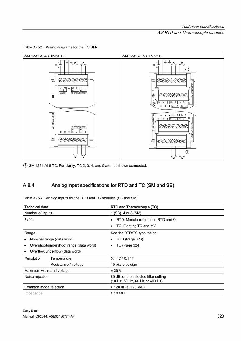
Technical specifications A.8 RTD and Thermocouple modules
Easy Book Manual, 03/2014, A5E02486774-AF 323
Table A- 52 Wiring diagrams for the TC SMs
SM 1231 AI 4 x 16 bit TC SM 1231 AI 8 x 16 bit TC
① SM 1231 AI 8 TC: For clarity, TC 2, 3, 4, and 5 are not shown connected.
A.8.4 Analog input specifications for RTD and TC (SM and SB)
Table A- 53 Analog inputs for the RTD and TC modules (SB and SM)
Technical data RTD and Thermocouple (TC) Number of inputs 1 (SB), 4 or 8 (SM) Type • RTD: Module referenced RTD and Ω
• TC: Floating TC and mV
Range • Nominal range (data word) • Overshoot/undershoot range (data word) • Overflow/underflow (data word)
See the RTD/TC type tables: • RTD (Page 326) • TC (Page 324)
Resolution Temperature 0.1 °C / 0.1 °F Resistance / voltage 15 bits plus sign
Maximum withstand voltage ± 35 V Noise rejection 85 dB for the selected filter setting
(10 Hz, 50 Hz, 60 Hz or 400 Hz) Common mode rejection > 120 dB at 120 VAC Impedance ≥ 10 MΩ
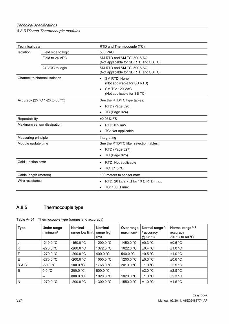
Technical specifications A.8 RTD and Thermocouple modules
Easy Book 324 Manual, 03/2014, A5E02486774-AF
Technical data RTD and Thermocouple (TC) Isolation Field side to logic 500 VAC
Field to 24 VDC SM RTD and SM TC: 500 VAC (Not applicable for SB RTD and SB TC)
24 VDC to logic SM RTD and SM TC: 500 VAC
(Not applicable for SB RTD and SB TC) Channel to channel isolation • SM RTD: None
(Not applicable for SB RTD) • SM TC: 120 VAC
(Not applicable for SB TC)
Accuracy (25 °C / -20 to 60 °C) See the RTD/TC type tables: • RTD (Page 326) • TC (Page 324)
Repeatability ±0.05% FS Maximum sensor dissipation • RTD: 0.5 mW
• TC: Not applicable
Measuring principle Integrating Module update time See the RTD/TC filter selection tables:
• RTD (Page 327) • TC (Page 325)
Cold junction error • RTD: Not applicable • TC: ±1.5 °C
Cable length (meters) 100 meters to sensor max. Wire resistance • RTD: 20 Ω, 2.7 Ω for 10 Ω RTD max.
• TC: 100 Ω max.
A.8.5 Thermocouple type
Table A- 54 Thermocouple type (ranges and accuracy)
Type Under range minimum1
Nominal range low limit
Nominal range high limit
Over range maximum2
Normal range 3,
4 accuracy @ 25 °C
Normal range 3, 4
accuracy -20 °C to 60 °C
J -210.0 °C -150.0 °C 1200.0 °C 1450.0 °C ±0.3 °C ±0.6 °C K -270.0 °C -200.0 °C 1372.0 °C 1622.0 °C ±0.4 °C ±1.0 °C T -270.0 °C -200.0 °C 400.0 °C 540.0 °C ±0.5 °C ±1.0 °C E -270.0 °C -200.0 °C 1000.0 °C 1200.0 °C ±0.3 °C ±0.6 °C R & S -50.0 °C 100.0 °C 1768.0 °C 2019.0 °C ±1.0 °C ±2.5 °C B 0.0 °C 200.0 °C 800.0 °C -- ±2.0 °C ±2.5 °C
-- 800.0 °C 1820.0 °C 1820.0 °C ±1.0 °C ±2.3 °C N -270.0 °C -200.0 °C 1300.0 °C 1550.0 °C ±1.0 °C ±1.6 °C
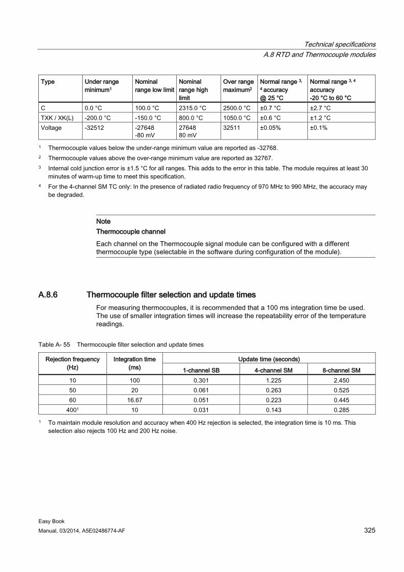
Technical specifications A.8 RTD and Thermocouple modules
Easy Book Manual, 03/2014, A5E02486774-AF 325
Type Under range minimum1
Nominal range low limit
Nominal range high limit
Over range maximum2
Normal range 3,
4 accuracy @ 25 °C
Normal range 3, 4
accuracy -20 °C to 60 °C
C 0.0 °C 100.0 °C 2315.0 °C 2500.0 °C ±0.7 °C ±2.7 °C TXK / XK(L) -200.0 °C -150.0 °C 800.0 °C 1050.0 °C ±0.6 °C ±1.2 °C Voltage -32512 -27648
-80 mV 27648 80 mV
32511 ±0.05% ±0.1%
1 Thermocouple values below the under-range minimum value are reported as -32768. 2 Thermocouple values above the over-range minimum value are reported as 32767. 3 Internal cold junction error is ±1.5 °C for all ranges. This adds to the error in this table. The module requires at least 30
minutes of warm-up time to meet this specification. 4 For the 4-channel SM TC only: In the presence of radiated radio frequency of 970 MHz to 990 MHz, the accuracy may
be degraded.
Note Thermocouple channel
Each channel on the Thermocouple signal module can be configured with a different thermocouple type (selectable in the software during configuration of the module).
A.8.6 Thermocouple filter selection and update times For measuring thermocouples, it is recommended that a 100 ms integration time be used. The use of smaller integration times will increase the repeatability error of the temperature readings.
Table A- 55 Thermocouple filter selection and update times
Rejection frequency (Hz)
Integration time (ms)
Update time (seconds)
1-channel SB 4-channel SM 8-channel SM 10 100 0.301 1.225 2.450 50 20 0.061 0.263 0.525 60 16.67 0.051 0.223 0.445
4001 10 0.031 0.143 0.285 1 To maintain module resolution and accuracy when 400 Hz rejection is selected, the integration time is 10 ms. This
selection also rejects 100 Hz and 200 Hz noise.
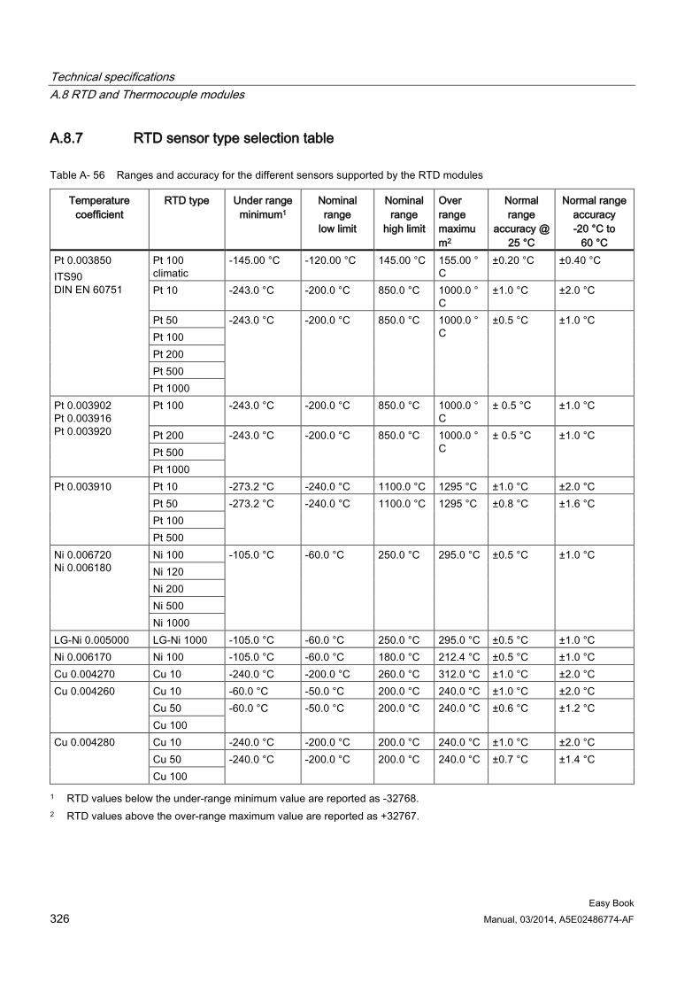
Technical specifications A.8 RTD and Thermocouple modules
Easy Book 326 Manual, 03/2014, A5E02486774-AF
A.8.7 RTD sensor type selection table
Table A- 56 Ranges and accuracy for the different sensors supported by the RTD modules
Temperature coefficient
RTD type Under range minimum1
Nominal range
low limit
Nominal range
high limit
Over range maximum2
Normal range
accuracy @ 25 °C
Normal range accuracy -20 °C to
60 °C Pt 0.003850 ITS90 DIN EN 60751
Pt 100 climatic
-145.00 °C -120.00 °C 145.00 °C 155.00 °C
±0.20 °C ±0.40 °C
Pt 10 -243.0 °C -200.0 °C 850.0 °C 1000.0 °C
±1.0 °C ±2.0 °C
Pt 50 -243.0 °C -200.0 °C 850.0 °C 1000.0 °C
±0.5 °C ±1.0 °C Pt 100 Pt 200 Pt 500 Pt 1000
Pt 0.003902 Pt 0.003916 Pt 0.003920
Pt 100 -243.0 °C -200.0 °C 850.0 °C 1000.0 °C
± 0.5 °C ±1.0 °C
Pt 200 -243.0 °C -200.0 °C 850.0 °C 1000.0 °C
± 0.5 °C ±1.0 °C Pt 500 Pt 1000
Pt 0.003910 Pt 10 -273.2 °C -240.0 °C 1100.0 °C 1295 °C ±1.0 °C ±2.0 °C Pt 50 -273.2 °C -240.0 °C 1100.0 °C 1295 °C ±0.8 °C ±1.6 °C Pt 100 Pt 500
Ni 0.006720 Ni 0.006180
Ni 100 -105.0 °C -60.0 °C 250.0 °C 295.0 °C ±0.5 °C ±1.0 °C Ni 120 Ni 200 Ni 500 Ni 1000
LG-Ni 0.005000 LG-Ni 1000 -105.0 °C -60.0 °C 250.0 °C 295.0 °C ±0.5 °C ±1.0 °C Ni 0.006170 Ni 100 -105.0 °C -60.0 °C 180.0 °C 212.4 °C ±0.5 °C ±1.0 °C Cu 0.004270 Cu 10 -240.0 °C -200.0 °C 260.0 °C 312.0 °C ±1.0 °C ±2.0 °C Cu 0.004260 Cu 10 -60.0 °C -50.0 °C 200.0 °C 240.0 °C ±1.0 °C ±2.0 °C
Cu 50 -60.0 °C -50.0 °C 200.0 °C 240.0 °C ±0.6 °C ±1.2 °C Cu 100
Cu 0.004280 Cu 10 -240.0 °C -200.0 °C 200.0 °C 240.0 °C ±1.0 °C ±2.0 °C Cu 50 -240.0 °C -200.0 °C 200.0 °C 240.0 °C ±0.7 °C ±1.4 °C Cu 100
1 RTD values below the under-range minimum value are reported as -32768. 2 RTD values above the over-range maximum value are reported as +32767.
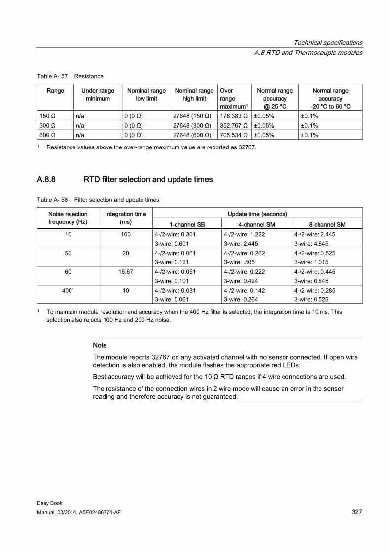
Technical specifications A.8 RTD and Thermocouple modules
Easy Book Manual, 03/2014, A5E02486774-AF 327
Table A- 57 Resistance
Range Under range minimum
Nominal range low limit
Nominal range high limit
Over range maximum1
Normal range accuracy @ 25 °C
Normal range accuracy
-20 °C to 60 °C 150 Ω n/a 0 (0 Ω) 27648 (150 Ω) 176.383 Ω ±0.05% ±0.1% 300 Ω n/a 0 (0 Ω) 27648 (300 Ω) 352.767 Ω ±0.05% ±0.1% 600 Ω n/a 0 (0 Ω) 27648 (600 Ω) 705.534 Ω ±0.05% ±0.1% 1 Resistance values above the over-range maximum value are reported as 32767.
A.8.8 RTD filter selection and update times
Table A- 58 Filter selection and update times
Noise rejection frequency (Hz)
Integration time (ms)
Update time (seconds)
1-channel SB 4-channel SM 8-channel SM 10 100 4-/2-wire: 0.301
3-wire: 0.601 4-/2-wire: 1.222 3-wire: 2.445
4-/2-wire: 2.445 3-wire: 4.845
50 20 4-/2-wire: 0.061 3-wire: 0.121
4-/2-wire: 0.262 3-wire: .505
4-/2-wire: 0.525 3-wire: 1.015
60 16.67 4-/2-wire: 0.051 3-wire: 0.101
4-/2-wire: 0.222 3-wire: 0.424
4-/2-wire: 0.445 3-wire: 0.845
4001 10 4-/2-wire: 0.031 3-wire: 0.061
4-/2-wire: 0.142 3-wire: 0.264
4-/2-wire: 0.285 3-wire: 0.525
1 To maintain module resolution and accuracy when the 400 Hz filter is selected, the integration time is 10 ms. This selection also rejects 100 Hz and 200 Hz noise.
Note
The module reports 32767 on any activated channel with no sensor connected. If open wire detection is also enabled, the module flashes the appropriate red LEDs.
Best accuracy will be achieved for the 10 Ω RTD ranges if 4 wire connections are used.
The resistance of the connection wires in 2 wire mode will cause an error in the sensor reading and therefore accuracy is not guaranteed.
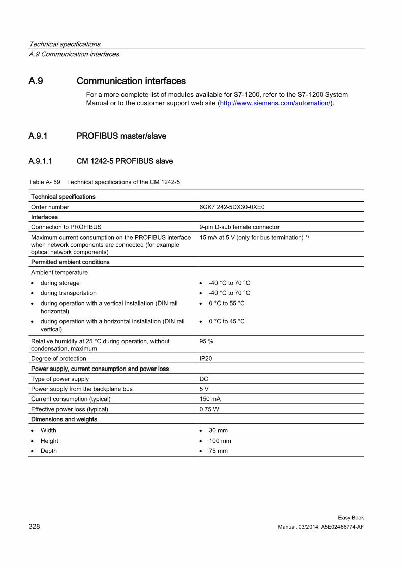
Technical specifications A.9 Communication interfaces
Easy Book 328 Manual, 03/2014, A5E02486774-AF
A.9 Communication interfaces For a more complete list of modules available for S7-1200, refer to the S7-1200 System Manual or to the customer support web site (http://www.siemens.com/automation/).
A.9.1 PROFIBUS master/slave
A.9.1.1 CM 1242-5 PROFIBUS slave
Table A- 59 Technical specifications of the CM 1242-5
Technical specifications Order number 6GK7 242-5DX30-0XE0 Interfaces Connection to PROFIBUS 9-pin D-sub female connector Maximum current consumption on the PROFIBUS interface when network components are connected (for example optical network components)
15 mA at 5 V (only for bus termination) *)
Permitted ambient conditions Ambient temperature • during storage • during transportation • during operation with a vertical installation (DIN rail
horizontal) • during operation with a horizontal installation (DIN rail
vertical)
• -40 °C to 70 °C • -40 °C to 70 °C • 0 °C to 55 °C
• 0 °C to 45 °C
Relative humidity at 25 °C during operation, without condensation, maximum
95 %
Degree of protection IP20 Power supply, current consumption and power loss Type of power supply DC Power supply from the backplane bus 5 V Current consumption (typical) 150 mA Effective power loss (typical) 0.75 W Dimensions and weights
• Width • Height • Depth
• 30 mm • 100 mm • 75 mm
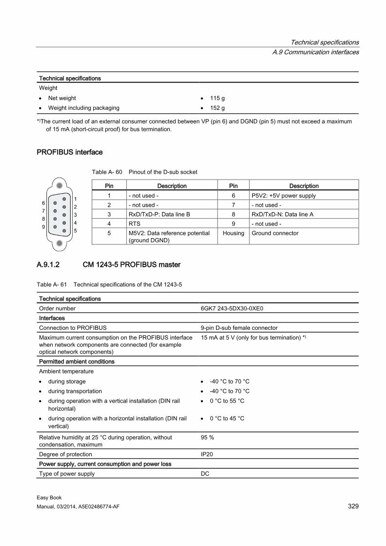
Technical specifications A.9 Communication interfaces
Easy Book Manual, 03/2014, A5E02486774-AF 329
Technical specifications Weight • Net weight • Weight including packaging
• 115 g • 152 g
*)The current load of an external consumer connected between VP (pin 6) and DGND (pin 5) must not exceed a maximum of 15 mA (short-circuit proof) for bus termination.
PROFIBUS interface
Table A- 60 Pinout of the D-sub socket
Pin Description Pin Description 1 - not used - 6 P5V2: +5V power supply 2 - not used - 7 - not used - 3 RxD/TxD-P: Data line B 8 RxD/TxD-N: Data line A 4 RTS 9 - not used - 5 M5V2: Data reference potential
(ground DGND) Housing Ground connector
A.9.1.2 CM 1243-5 PROFIBUS master
Table A- 61 Technical specifications of the CM 1243-5
Technical specifications Order number 6GK7 243-5DX30-0XE0 Interfaces Connection to PROFIBUS 9-pin D-sub female connector Maximum current consumption on the PROFIBUS interface when network components are connected (for example optical network components)
15 mA at 5 V (only for bus termination) *)
Permitted ambient conditions Ambient temperature • during storage • during transportation • during operation with a vertical installation (DIN rail
horizontal) • during operation with a horizontal installation (DIN rail
vertical)
• -40 °C to 70 °C • -40 °C to 70 °C • 0 °C to 55 °C
• 0 °C to 45 °C
Relative humidity at 25 °C during operation, without condensation, maximum
95 %
Degree of protection IP20 Power supply, current consumption and power loss Type of power supply DC
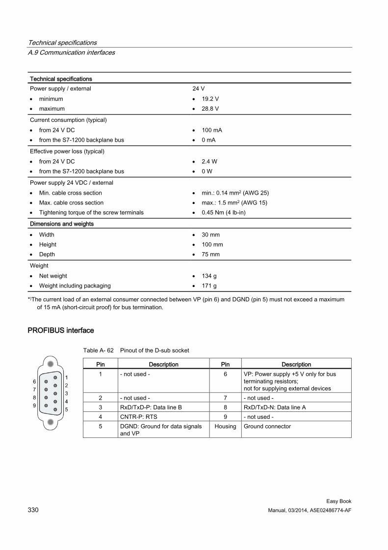
Technical specifications A.9 Communication interfaces
Easy Book 330 Manual, 03/2014, A5E02486774-AF
Technical specifications Power supply / external • minimum • maximum
24 V • 19.2 V • 28.8 V
Current consumption (typical) • from 24 V DC • from the S7-1200 backplane bus
• 100 mA • 0 mA
Effective power loss (typical) • from 24 V DC • from the S7-1200 backplane bus
• 2.4 W • 0 W
Power supply 24 VDC / external • Min. cable cross section • Max. cable cross section • Tightening torque of the screw terminals
• min.: 0.14 mm2 (AWG 25) • max.: 1.5 mm2 (AWG 15) • 0.45 Nm (4 lb-in)
Dimensions and weights
• Width • Height • Depth
• 30 mm • 100 mm • 75 mm
Weight • Net weight • Weight including packaging
• 134 g • 171 g
*)The current load of an external consumer connected between VP (pin 6) and DGND (pin 5) must not exceed a maximum of 15 mA (short-circuit proof) for bus termination.
PROFIBUS interface
Table A- 62 Pinout of the D-sub socket
Pin Description Pin Description 1 - not used - 6 VP: Power supply +5 V only for bus
terminating resistors; not for supplying external devices
2 - not used - 7 - not used - 3 RxD/TxD-P: Data line B 8 RxD/TxD-N: Data line A 4 CNTR-P: RTS 9 - not used - 5 DGND: Ground for data signals
and VP Housing Ground connector
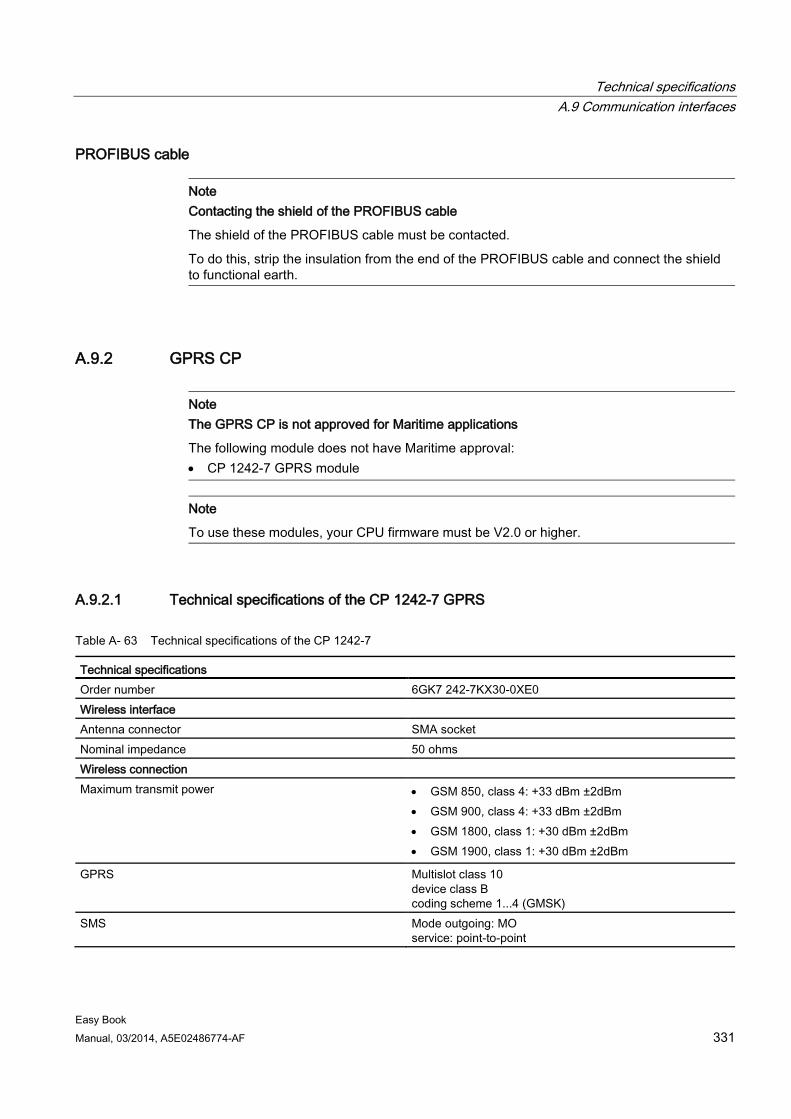
Technical specifications A.9 Communication interfaces
Easy Book Manual, 03/2014, A5E02486774-AF 331
PROFIBUS cable
Note Contacting the shield of the PROFIBUS cable
The shield of the PROFIBUS cable must be contacted.
To do this, strip the insulation from the end of the PROFIBUS cable and connect the shield to functional earth.
A.9.2 GPRS CP
Note The GPRS CP is not approved for Maritime applications
The following module does not have Maritime approval: • CP 1242-7 GPRS module
Note
To use these modules, your CPU firmware must be V2.0 or higher.
A.9.2.1 Technical specifications of the CP 1242-7 GPRS
Table A- 63 Technical specifications of the CP 1242-7
Technical specifications Order number 6GK7 242-7KX30-0XE0 Wireless interface Antenna connector SMA socket Nominal impedance 50 ohms Wireless connection Maximum transmit power • GSM 850, class 4: +33 dBm ±2dBm
• GSM 900, class 4: +33 dBm ±2dBm • GSM 1800, class 1: +30 dBm ±2dBm • GSM 1900, class 1: +30 dBm ±2dBm
GPRS Multislot class 10 device class B coding scheme 1...4 (GMSK)
SMS Mode outgoing: MO service: point-to-point
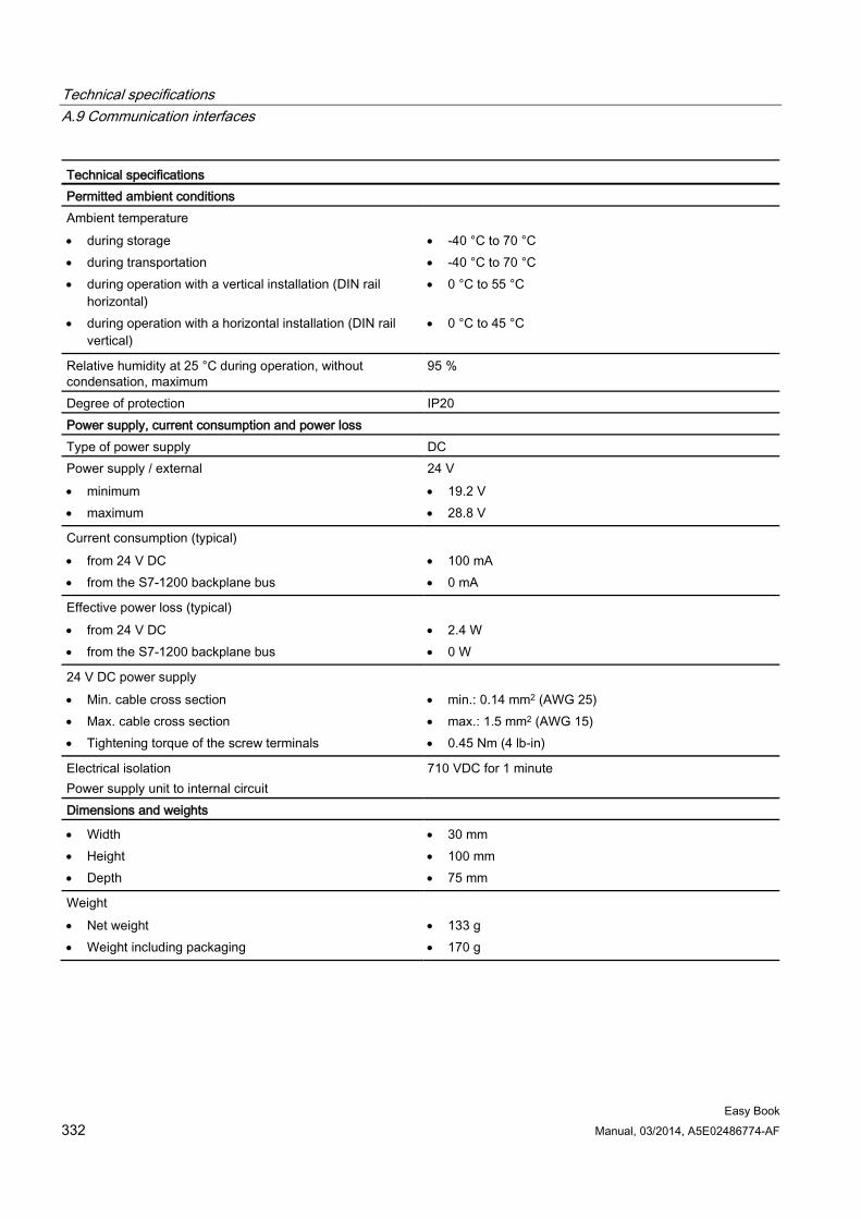
Technical specifications A.9 Communication interfaces
Easy Book 332 Manual, 03/2014, A5E02486774-AF
Technical specifications Permitted ambient conditions Ambient temperature • during storage • during transportation • during operation with a vertical installation (DIN rail
horizontal) • during operation with a horizontal installation (DIN rail
vertical)
• -40 °C to 70 °C • -40 °C to 70 °C • 0 °C to 55 °C
• 0 °C to 45 °C
Relative humidity at 25 °C during operation, without condensation, maximum
95 %
Degree of protection IP20 Power supply, current consumption and power loss Type of power supply DC Power supply / external • minimum • maximum
24 V • 19.2 V • 28.8 V
Current consumption (typical) • from 24 V DC • from the S7-1200 backplane bus
• 100 mA • 0 mA
Effective power loss (typical) • from 24 V DC • from the S7-1200 backplane bus
• 2.4 W • 0 W
24 V DC power supply • Min. cable cross section • Max. cable cross section • Tightening torque of the screw terminals
• min.: 0.14 mm2 (AWG 25) • max.: 1.5 mm2 (AWG 15) • 0.45 Nm (4 lb-in)
Electrical isolation Power supply unit to internal circuit
710 VDC for 1 minute
Dimensions and weights
• Width • Height • Depth
• 30 mm • 100 mm • 75 mm
Weight • Net weight • Weight including packaging
• 133 g • 170 g
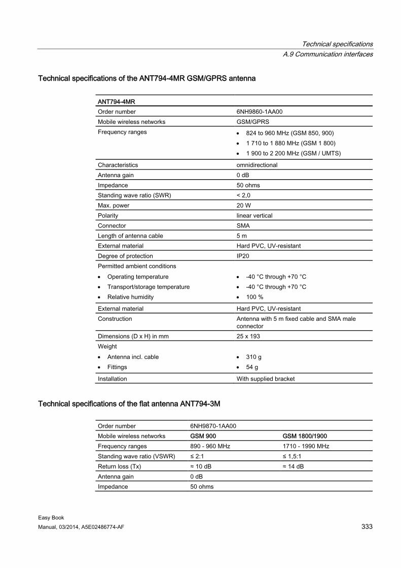
Technical specifications A.9 Communication interfaces
Easy Book Manual, 03/2014, A5E02486774-AF 333
Technical specifications of the ANT794-4MR GSM/GPRS antenna
ANT794-4MR Order number 6NH9860-1AA00 Mobile wireless networks GSM/GPRS Frequency ranges • 824 to 960 MHz (GSM 850, 900)
• 1 710 to 1 880 MHz (GSM 1 800) • 1 900 to 2 200 MHz (GSM / UMTS)
Characteristics omnidirectional Antenna gain 0 dB Impedance 50 ohms Standing wave ratio (SWR) < 2,0 Max. power 20 W Polarity linear vertical Connector SMA Length of antenna cable 5 m External material Hard PVC, UV-resistant Degree of protection IP20 Permitted ambient conditions • Operating temperature • Transport/storage temperature • Relative humidity
• -40 °C through +70 °C • -40 °C through +70 °C • 100 %
External material Hard PVC, UV-resistant Construction Antenna with 5 m fixed cable and SMA male
connector Dimensions (D x H) in mm 25 x 193 Weight • Antenna incl. cable • Fittings
• 310 g • 54 g
Installation With supplied bracket
Technical specifications of the flat antenna ANT794-3M Order number 6NH9870-1AA00 Mobile wireless networks GSM 900 GSM 1800/1900 Frequency ranges 890 - 960 MHz 1710 - 1990 MHz Standing wave ratio (VSWR) ≤ 2:1 ≤ 1,5:1 Return loss (Tx) ≈ 10 dB ≈ 14 dB Antenna gain 0 dB Impedance 50 ohms
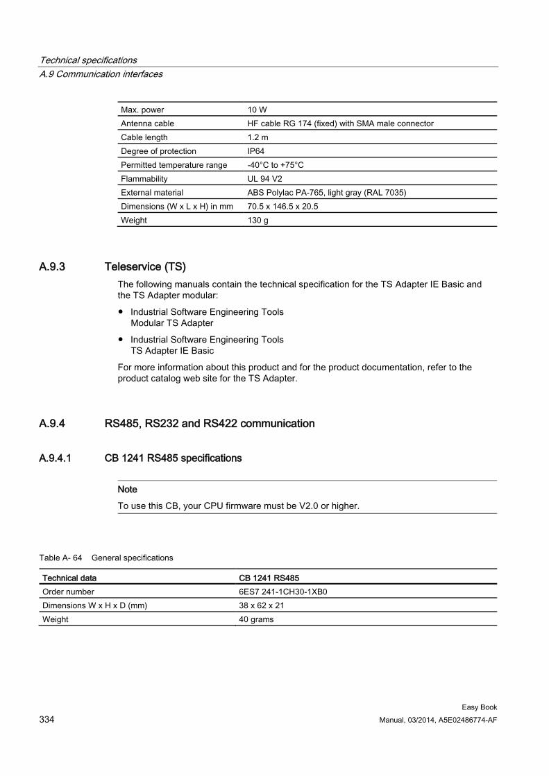
Technical specifications A.9 Communication interfaces
Easy Book 334 Manual, 03/2014, A5E02486774-AF
Max. power 10 W Antenna cable HF cable RG 174 (fixed) with SMA male connector Cable length 1.2 m Degree of protection IP64 Permitted temperature range -40°C to +75°C Flammability UL 94 V2 External material ABS Polylac PA-765, light gray (RAL 7035) Dimensions (W x L x H) in mm 70.5 x 146.5 x 20.5 Weight 130 g
A.9.3 Teleservice (TS) The following manuals contain the technical specification for the TS Adapter IE Basic and the TS Adapter modular:
● Industrial Software Engineering Tools Modular TS Adapter
● Industrial Software Engineering Tools TS Adapter IE Basic
For more information about this product and for the product documentation, refer to the product catalog web site for the TS Adapter.
A.9.4 RS485, RS232 and RS422 communication
A.9.4.1 CB 1241 RS485 specifications
Note
To use this CB, your CPU firmware must be V2.0 or higher.
Table A- 64 General specifications
Technical data CB 1241 RS485 Order number 6ES7 241-1CH30-1XB0 Dimensions W x H x D (mm) 38 x 62 x 21 Weight 40 grams
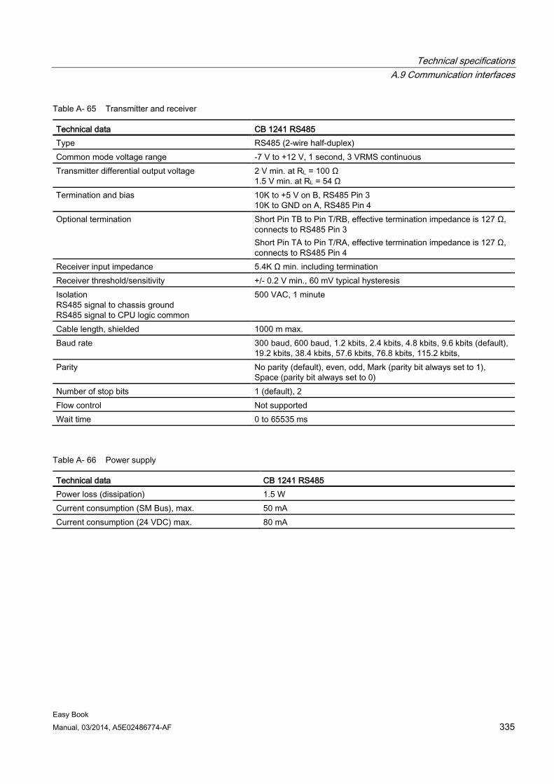
Technical specifications A.9 Communication interfaces
Easy Book Manual, 03/2014, A5E02486774-AF 335
Table A- 65 Transmitter and receiver
Technical data CB 1241 RS485 Type RS485 (2-wire half-duplex) Common mode voltage range -7 V to +12 V, 1 second, 3 VRMS continuous Transmitter differential output voltage 2 V min. at RL = 100 Ω
1.5 V min. at RL = 54 Ω Termination and bias 10K to +5 V on B, RS485 Pin 3
10K to GND on A, RS485 Pin 4 Optional termination Short Pin TB to Pin T/RB, effective termination impedance is 127 Ω,
connects to RS485 Pin 3 Short Pin TA to Pin T/RA, effective termination impedance is 127 Ω, connects to RS485 Pin 4
Receiver input impedance 5.4K Ω min. including termination Receiver threshold/sensitivity +/- 0.2 V min., 60 mV typical hysteresis Isolation RS485 signal to chassis ground RS485 signal to CPU logic common
500 VAC, 1 minute
Cable length, shielded 1000 m max. Baud rate 300 baud, 600 baud, 1.2 kbits, 2.4 kbits, 4.8 kbits, 9.6 kbits (default),
19.2 kbits, 38.4 kbits, 57.6 kbits, 76.8 kbits, 115.2 kbits, Parity No parity (default), even, odd, Mark (parity bit always set to 1),
Space (parity bit always set to 0) Number of stop bits 1 (default), 2 Flow control Not supported Wait time 0 to 65535 ms
Table A- 66 Power supply
Technical data CB 1241 RS485 Power loss (dissipation) 1.5 W Current consumption (SM Bus), max. 50 mA Current consumption (24 VDC) max. 80 mA
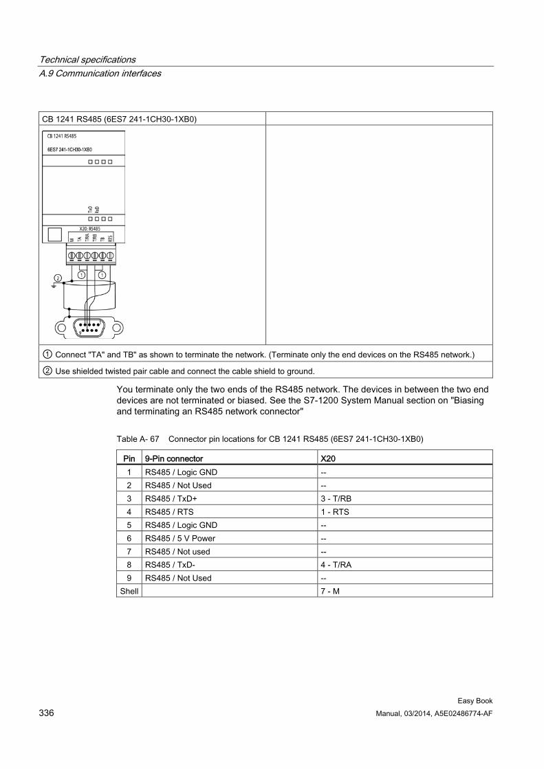
Technical specifications A.9 Communication interfaces
Easy Book 336 Manual, 03/2014, A5E02486774-AF
CB 1241 RS485 (6ES7 241-1CH30-1XB0)
① Connect "TA" and TB" as shown to terminate the network. (Terminate only the end devices on the RS485 network.)
② Use shielded twisted pair cable and connect the cable shield to ground.
You terminate only the two ends of the RS485 network. The devices in between the two end devices are not terminated or biased. See the S7-1200 System Manual section on "Biasing and terminating an RS485 network connector"
Table A- 67 Connector pin locations for CB 1241 RS485 (6ES7 241-1CH30-1XB0)
Pin 9-Pin connector X20 1 RS485 / Logic GND -- 2 RS485 / Not Used -- 3 RS485 / TxD+ 3 - T/RB 4 RS485 / RTS 1 - RTS 5 RS485 / Logic GND -- 6 RS485 / 5 V Power -- 7 RS485 / Not used -- 8 RS485 / TxD- 4 - T/RA 9 RS485 / Not Used --
Shell 7 - M
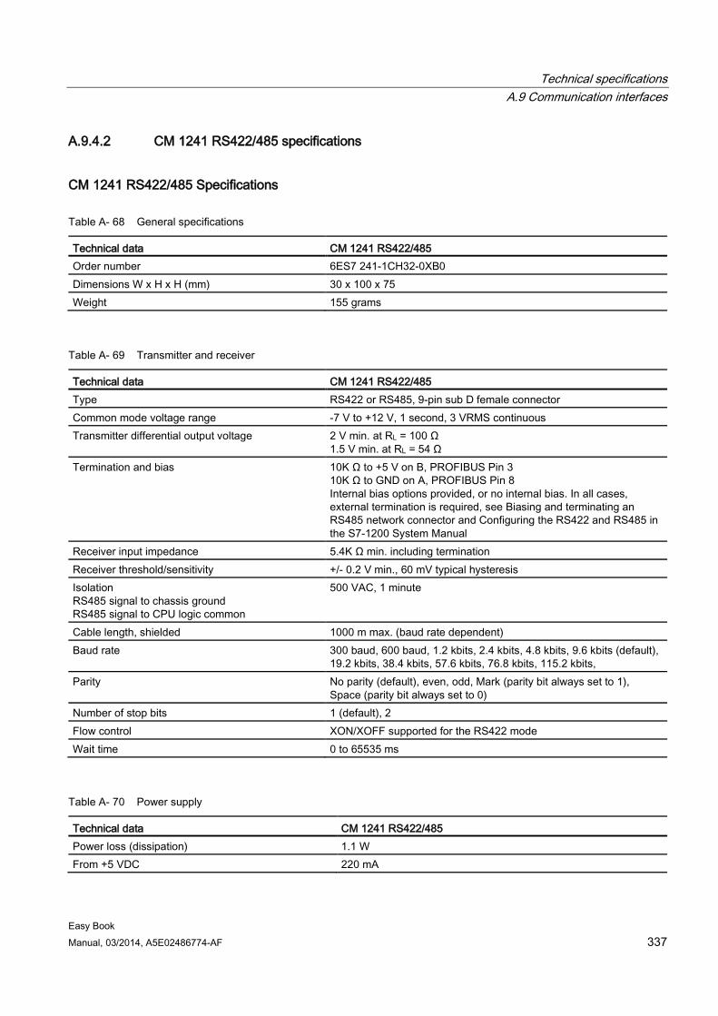
Technical specifications A.9 Communication interfaces
Easy Book Manual, 03/2014, A5E02486774-AF 337
A.9.4.2 CM 1241 RS422/485 specifications
CM 1241 RS422/485 Specifications
Table A- 68 General specifications
Technical data CM 1241 RS422/485 Order number 6ES7 241-1CH32-0XB0 Dimensions W x H x H (mm) 30 x 100 x 75 Weight 155 grams
Table A- 69 Transmitter and receiver
Technical data CM 1241 RS422/485 Type RS422 or RS485, 9-pin sub D female connector Common mode voltage range -7 V to +12 V, 1 second, 3 VRMS continuous Transmitter differential output voltage 2 V min. at RL = 100 Ω
1.5 V min. at RL = 54 Ω Termination and bias 10K Ω to +5 V on B, PROFIBUS Pin 3
10K Ω to GND on A, PROFIBUS Pin 8 Internal bias options provided, or no internal bias. In all cases, external termination is required, see Biasing and terminating an RS485 network connector and Configuring the RS422 and RS485 in the S7-1200 System Manual
Receiver input impedance 5.4K Ω min. including termination Receiver threshold/sensitivity +/- 0.2 V min., 60 mV typical hysteresis Isolation RS485 signal to chassis ground RS485 signal to CPU logic common
500 VAC, 1 minute
Cable length, shielded 1000 m max. (baud rate dependent) Baud rate 300 baud, 600 baud, 1.2 kbits, 2.4 kbits, 4.8 kbits, 9.6 kbits (default),
19.2 kbits, 38.4 kbits, 57.6 kbits, 76.8 kbits, 115.2 kbits, Parity No parity (default), even, odd, Mark (parity bit always set to 1),
Space (parity bit always set to 0) Number of stop bits 1 (default), 2 Flow control XON/XOFF supported for the RS422 mode Wait time 0 to 65535 ms
Table A- 70 Power supply
Technical data CM 1241 RS422/485 Power loss (dissipation) 1.1 W From +5 VDC 220 mA
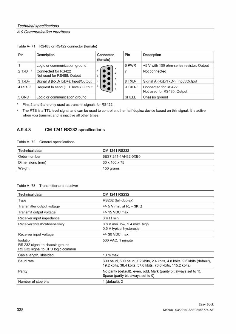
Technical specifications A.9 Communication interfaces
Easy Book 338 Manual, 03/2014, A5E02486774-AF
Table A- 71 RS485 or RS422 connector (female)
Pin Description Connector (female)
Pin Description
1 Logic or communication ground
6 PWR +5 V with 100 ohm series resistor: Output 2 TxD+ 1 Connected for RS422
Not used for RS485: Output 7 Not connected
3 TxD+ Signal B (RxD/TxD+): Input/Output 8 TXD- Signal A (RxD/TxD-): Input/Output 4 RTS 2 Request to send (TTL level) Output 9 TXD- 1 Connected for RS422
Not used for RS485: Output 5 GND Logic or communication ground SHELL Chassis ground 1 Pins 2 and 9 are only used as transmit signals for RS422.
2 The RTS is a TTL level signal and can be used to control another half duplex device based on this signal. It is active when you transmit and is inactive all other times.
A.9.4.3 CM 1241 RS232 specifications
Table A- 72 General specifications
Technical data CM 1241 RS232 Order number 6ES7 241-1AH32-0XB0 Dimensions (mm) 30 x 100 x 75 Weight 150 grams
Table A- 73 Transmitter and receiver
Technical data CM 1241 RS232 Type RS232 (full-duplex) Transmitter output voltage +/- 5 V min. at RL = 3K Ω Transmit output voltage +/- 15 VDC max. Receiver input impedance 3 K Ω min. Receiver threshold/sensitivity 0.8 V min. low, 2.4 max. high
0.5 V typical hysteresis Receiver input voltage +/- 30 VDC max. Isolation RS 232 signal to chassis ground RS 232 signal to CPU logic common
500 VAC, 1 minute
Cable length, shielded 10 m max. Baud rate 300 baud, 600 baud, 1.2 kbits, 2.4 kbits, 4.8 kbits, 9.6 kbits (default),
19.2 kbits, 38.4 kbits, 57.6 kbits, 76.8 kbits, 115.2 kbits, Parity No parity (default), even, odd, Mark (parity bit always set to 1),
Space (parity bit always set to 0) Number of stop bits 1 (default), 2
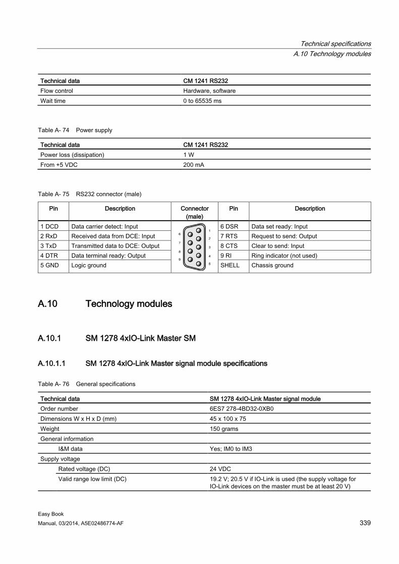
Technical specifications A.10 Technology modules
Easy Book Manual, 03/2014, A5E02486774-AF 339
Technical data CM 1241 RS232 Flow control Hardware, software Wait time 0 to 65535 ms
Table A- 74 Power supply
Technical data CM 1241 RS232 Power loss (dissipation) 1 W From +5 VDC 200 mA
Table A- 75 RS232 connector (male)
Pin Description Connector (male)
Pin Description
1 DCD Data carrier detect: Input
6 DSR Data set ready: Input 2 RxD Received data from DCE: Input 7 RTS Request to send: Output 3 TxD Transmitted data to DCE: Output 8 CTS Clear to send: Input 4 DTR Data terminal ready: Output 9 RI Ring indicator (not used) 5 GND Logic ground SHELL Chassis ground
A.10 Technology modules
A.10.1 SM 1278 4xIO-Link Master SM
A.10.1.1 SM 1278 4xIO-Link Master signal module specifications
Table A- 76 General specifications
Technical data SM 1278 4xIO-Link Master signal module Order number 6ES7 278-4BD32-0XB0 Dimensions W x H x D (mm) 45 x 100 x 75 Weight 150 grams General information I&M data Yes; IM0 to IM3 Supply voltage Rated voltage (DC) 24 VDC
Valid range low limit (DC) 19.2 V; 20.5 V if IO-Link is used (the supply voltage for IO-Link devices on the master must be at least 20 V)
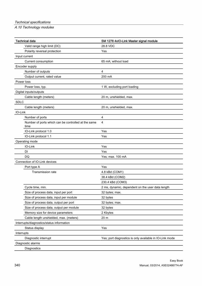
Technical specifications A.10 Technology modules
Easy Book 340 Manual, 03/2014, A5E02486774-AF
Technical data SM 1278 4xIO-Link Master signal module Valid range high limit (DC) 28.8 VDC Polarity reversal protection Yes
Input current Current consumption 65 mA; without load Encoder supply Number of outputs 4
Output current, rated value 200 mA Power loss Power loss, typ. 1 W, excluding port loading Digital inputs/outputs Cable length (meters) 20 m, unshielded, max. SDLC Cable length (meters) 20 m, unshielded, max. IO-Link Number of ports 4
Number of ports which can be controlled at the same time
4
IO-Link protocol 1.0 Yes IO-Link protocol 1.1 Yes
Operating mode IO-Link Yes DI Yes DQ Yes; max. 100 mA Connection of IO-Link devices Port type A Yes
Transmission rate 4.8 kBd (COM1) 38.4 kBd (COM2) 230.4 kBd (COM3)
Cycle time, min. 2 ms, dynamic, dependent on the user data length Size of process data, input per port 32 bytes; max. Size of process data, input per module 32 bytes Size of process data, output per port 32 bytes; max. Size of process data, output per module 32 bytes Memory size for device parameters 2 Kbytes Cable length unshielded, max. (meters) 20 m
Interrupts/diagnostics/status information Status display Yes Interrupts Diagnostic interrupt Yes; port diagnostics is only available in IO-Link mode Diagnostic alarms Diagnostics
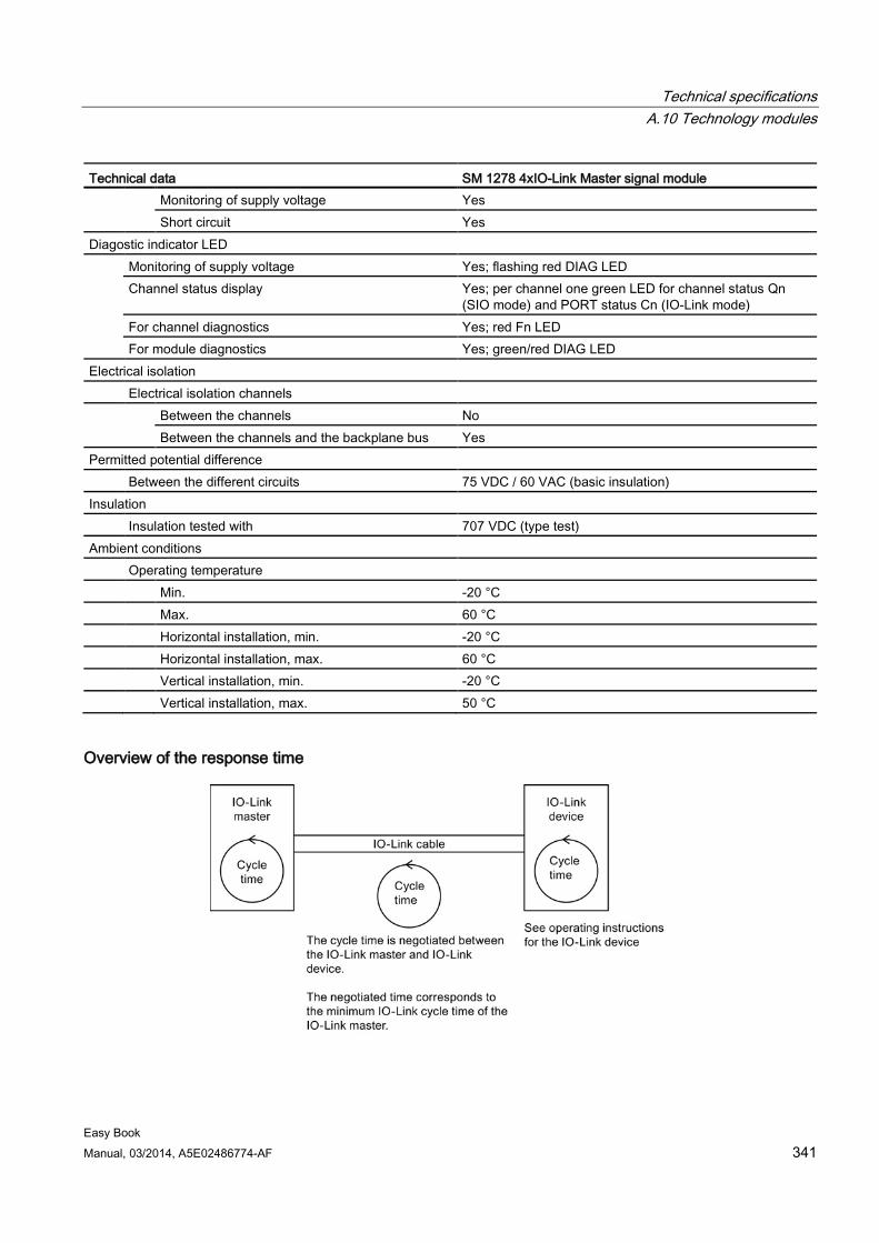
Technical specifications A.10 Technology modules
Easy Book Manual, 03/2014, A5E02486774-AF 341
Technical data SM 1278 4xIO-Link Master signal module
Monitoring of supply voltage Yes Short circuit Yes
Diagostic indicator LED Monitoring of supply voltage Yes; flashing red DIAG LED
Channel status display Yes; per channel one green LED for channel status Qn (SIO mode) and PORT status Cn (IO-Link mode)
For channel diagnostics Yes; red Fn LED For module diagnostics Yes; green/red DIAG LED
Electrical isolation Electrical isolation channels Between the channels No
Between the channels and the backplane bus Yes Permitted potential difference Between the different circuits 75 VDC / 60 VAC (basic insulation) Insulation Insulation tested with 707 VDC (type test) Ambient conditions Operating temperature Min. -20 °C Max. 60 °C Horizontal installation, min. -20 °C Horizontal installation, max. 60 °C Vertical installation, min. -20 °C Vertical installation, max. 50 °C
Overview of the response time
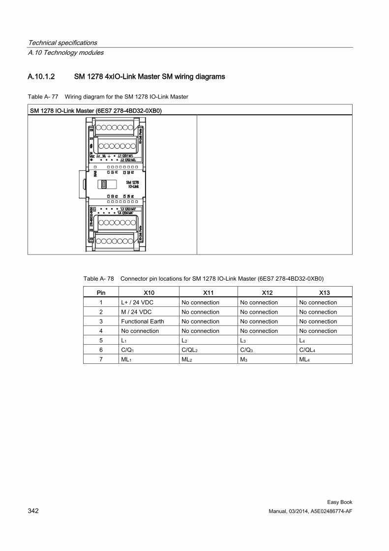
Technical specifications A.10 Technology modules
Easy Book 342 Manual, 03/2014, A5E02486774-AF
A.10.1.2 SM 1278 4xIO-Link Master SM wiring diagrams
Table A- 77 Wiring diagram for the SM 1278 IO-Link Master
SM 1278 IO-Link Master (6ES7 278-4BD32-0XB0)
Table A- 78 Connector pin locations for SM 1278 IO-Link Master (6ES7 278-4BD32-0XB0)
Pin X10 X11 X12 X13 1 L+ / 24 VDC No connection No connection No connection 2 M / 24 VDC No connection No connection No connection 3 Functional Earth No connection No connection No connection 4 No connection No connection No connection No connection 5 L1 L2 L3 L4 6 C/Q1 C/QL2 C/Q3 C/QL4 7 ML1 ML2 M3 ML4
Technical specifications A.11 Companion products
Easy Book Manual, 03/2014, A5E02486774-AF 343
A.11 Companion products
A.11.1 PM 1207 power module The PM 1207 is a power supply module for the SIMATIC S7-1200. It provides the following features:
● Input 120/230 VAC, output 24 VDC/2.5A
● Order number 6ESP 332-1SH71-4AA0
For more information about this product and for the product documentation, refer to the product catalog web site for the PM 1207.
See also Customer support (http://www.siemens.com/automation/)
A.11.2 CSM 1277 compact switch module The CSM1277 is an Industrial Ethernet compact switch module. It can be used to multiply the Ethernet interface of the S7-1200 to allow simultaneous communication with operator panels, programming devices, or other controllers. It provides the following features:
● 4 x RJ45 sockets for connecting to Industrial Ethernet
● 3 pole plug in terminal strip for connection of the external 24 VDC supply on top
● LEDs for diagnostics and status display of Industrial Ethernet ports
● Order number 6GK7 277-1AA00-0AA0
For more information about this product and for the product documentation, refer to the product catalog web site for the CSM 1277.
See also Customer support (http://www.siemens.com/automation/)
Technical specifications A.11 Companion products
Easy Book 344 Manual, 03/2014, A5E02486774-AF
A.11.3 CM CANopen module The CM CANopen module is a plug-in module between the SIMATIC S7-1200 PLC and any device running CANopen. The CM CANopen can be configured to be both master or slave. There are two CM CANopen modules: the CANopen module (order number 021620-B), and the CANopen (Ruggedized) module (order number 021730-B).
The CANopen module provides the following features:
● Able to connect 3 modules per CPU
● Connects up to 16 CANopen slave nodes
● 256 byte input and 256 byte output per module
● 3 LEDs provide diagnostic information on module, network, and I/O status
● Supports storage of CANopen network configuration in the PLC
● The module is integratable in the hardware catalogue of the TIA Portal configuration suite
● CANopen configuration via included CANopen Configuration Studio (included) or via any other externanal CANopen configuration tool
● Complies to the CANopen communication profiles CiA 301 rev. 4.2 and the CiA 302 rev. 4.1
● Supports transparent CAN 2.0A for custom protocol handling
● Pre-made function blocks available for each PLC programming in TIA portal
● CM CANopen modules include; DSUB with screw terminals for subnetwork. CM CANopen configuration studio CD, and USB configuration cable
For more information about this product and for the product documentation, refer to the product catalog web site for the CM CANopen.
Easy Book Manual, 03/2014, A5E02486774-AF 345
Exchanging a V3.0 CPU for a V4.0 CPU B B.1 Exchanging a V3.0 CPU for a V4.0 CPU
You can replace your V3.0 CPU with a V4.0 CPU (Page 74) and use your existing STEP 7 project that you designed for the V3.0 CPU. You might also want to check for and apply firmware updates (Page 269) to your connected modules.
Note No device exchange possible from V4.0 to V3.0
You can exchange a V3.0 CPU for a V4.0 CPU, but you cannot exchange a V4.0 CPU for a V3.0 CPU after you download the configuration. If you want to view or otherwise use your existing STEP 7 V3.0 project, make an archive of your STEP 7 V3.0 project prior to the device exchange.
Note that if you have not downloaded the exchanged device configuration, you can undo it. After downloading, however, you cannot undo the exchange from V3.0 to V4.0.
You need to be aware of some configuration and operational changes between the two CPU versions:
Organization blocks With V4.0, you can configure OB execution to be interruptible or non-interruptible (Page 55). For projects from former V3.0 CPUs, STEP 7 sets all OBs by default to be non-interruptible.
STEP 7 sets all OB priorities (Page 55) to the values they were in the V3.0 CPU STEP 7 project.
You can subsequently change the interruptability or priority settings if you choose.
The Diagnostic error interrupt OB start information references the submodule as a whole if no diagnostics event is pending.
CPU password protection STEP 7 sets the password protection level (Page 82) for the V4.0 CPU to be the equivalent password protection level that was set for the V3.0 CPU, and assigns the V3.0 password to the "Full access (no protection)" password for the V4.0 CPU:
V3.0 protection level V4.0 access level No protection Full access (no protection) Write protection Read access Write/read protection HMI access
Note that the V4.0 access level "No access (complete protection)" did not exist for V3.0.
Exchanging a V3.0 CPU for a V4.0 CPU B.1 Exchanging a V3.0 CPU for a V4.0 CPU
Easy Book 346 Manual, 03/2014, A5E02486774-AF
Web server If you exchange a V3.0 CPU for a V4.0 CPU, your Web server project settings for activating the Web server and whether or not to require HTTPS access will be the same as they were in V3.0. You can then configure users, privileges, passwords (Page 193), and languages as needed to use the Web server. If you do not configure users with additional privileges, then you are limited as to what you can view from the standard Web pages (Page 194). The S7-1200 V4.0 CPU does not support the former pre-configured "admin" user and password.
Formerly, the Data log Web server page provided a "Download and Clear" operation. The V4.0 Web server File browser page (Page 194), from which you access data logs, no longer provides this feature. Instead, the Web server provides the ability to download, rename, and delete data log files.
Transfer card incompatibility You cannot use a V3.0 transfer card (Page 58) to transfer a V3.0 program to a V4.0 CPU. You must open the V3.0 project in STEP 7, change the device to a V4.0 CPU (Page 74), and download the STEP 7 project to your V4.0 CPU. After you have changed your project to a V4.0 project, you can then make a V4.0 transfer card for subsequent program transfers.
GET/PUT communication By default, GET/PUT communication was enabled in V3.0. When you replace your V3.0 CPU with a V4.0 CPU (Page 74), you see a message in the compatibility information section stating that GET/PUT is enabled.
Motion control support S7-1200 V4.0 CPUs do not support the V1.0 and V2.0 motion libraries. If you perform a device exchange for a STEP 7 project with V1.0 or V2.0 motion libraries, the device exchange substitutes compatible V3.0 motion control instructions (Page 217) for the V1.0 or V2.0 motion library instructions at compile.
If you perform a device exchange for a STEP 7 project that contains two different motion control instruction versions (V3.0 and V4.0), the device exchange substitutes compatible V4.0 motion control instructions (Page 217) at compile.
During a device exchange from V3.0 to V4.0, the motion control Technological Object (TO) version automatically changes to V4.0. The TO structure is different between V3.0 and V4.0. All associated blocks change as well. Block interfaces, watch tables, and traces update to the new V4.0 structure. You can find the differences between the V3.0 and V4.0 motion control axis parameters in the following two tables:
V3.0 V4.0
Config.General.LengthUnit Units.LengthUnit Config.Mechanics.PulsesPerDriveRevolution Actor.DriveParameter.PulsesPerDriveRevolution Config.Mechanics.LeadScrew Mechanics.LeadScrew Config.Mechanics.InverseDirection Actor.InverseDirection Config.DynamicLimits.MinVelocity DynamicLimits.MinVelocity
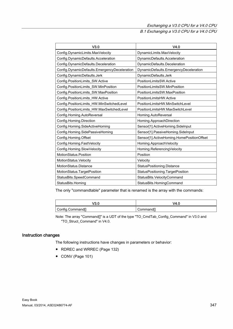
Exchanging a V3.0 CPU for a V4.0 CPU B.1 Exchanging a V3.0 CPU for a V4.0 CPU
Easy Book Manual, 03/2014, A5E02486774-AF 347
V3.0 V4.0 Config.DynamicLimits.MaxVelocity DynamicLimits.MaxVelocity Config.DynamicDefaults.Acceleration DynamicDefaults.Acceleration Config.DynamicDefaults.Deceleration DynamicDefaults.Deceleration Config.DynamicDefaults.EmergencyDeceleration DynamicDefaults.EmergencyDeceleration Config.DynamicDefaults.Jerk DynamicDefaults.Jerk Config.PositionLimits_SW.Active PositionLimitsSW.Active Config.PositionLimits_SW.MinPosition PositionLimitsSW.MinPosition Config.PositionLimits_SW.MaxPosition PositionLimitsSW.MaxPosition Config.PositionLimits_HW.Active PositionLimitsHW.Active Config.PositionLimits_HW.MinSwitchedLevel PositionLimitsHW.MinSwitchLevel Config.PositionLimits_HW.MaxSwitchedLevel PositionLimitsHW.MaxSwitchLevel Config.Homing.AutoReversal Homing.AutoReversal Config.Homing.Direction Homing.ApproachDirection Config.Homing.SideActiveHoming Sensor[1].ActiveHoming.SideInput Config.Homing.SidePassiveHoming Sensor[1].PassiveHoming.SideInput Config.Homing.Offset Sensor[1].ActiveHoming.HomePositionOffset Config.Homing.FastVelocity Homing.ApproachVelocity Config.Homing.SlowVelocity Homing.ReferencingVelocity MotionStatus.Position Position MotionStatus.Velocity Velocity MotionStatus.Distance StatusPositioning.Distance MotionStatus.TargetPosition StatusPositioning.TargetPosition StatusBits.SpeedCommand StatusBits.VelocityCommand StatusBits.Homing StatusBits.HomingCommand
The only "commandtable" parameter that is renamed is the array with the commands:
V3.0 V4.0
Config.Command[] Command[] Note: The array "Command[]" is a UDT of the type "TO_CmdTab_Config_Command" in V3.0 and
"TO_Struct_Command" in V4.0.
Instruction changes The following instructions have changes in parameters or behavior:
● RDREC and WRREC (Page 132)
● CONV (Page 101)
Exchanging a V3.0 CPU for a V4.0 CPU B.1 Exchanging a V3.0 CPU for a V4.0 CPU
Easy Book 348 Manual, 03/2014, A5E02486774-AF
HMI panel communication If you had one or more HMI panels (Page 22) connected to your S7-1200 V3.0 CPU, the communication to the S7-1200 V4.0 CPU depends on the type of communication you use and the firmware version of the HMI panel. Recompile and download your project to the CPU and the HMI and/or update your HMI firmware.
Requirement to recompile program blocks After exchanging a V3.0 CPU for a V4.0 CPU, you must recompile all program blocks before you can download them to the V4.0 CPU. Additionally, if any of the blocks have know-how protection (Page 84) or copy protection bound to a PLC serial number (Page 85), you must remove the protection before you compile and download the blocks. (You do not, however, need to deactivate copy protection bound to a memory card.) After the download, you can reconfigure the know-how protection and/or PLC serial number copy protection. Note that if your project includes any blocks with know-how protection that an OEM (Original Equipment Manufacturer) provided, you must contact the OEM to provide V4.0 versions of those blocks.
In general, Siemens recommends that you recompile the hardware configuration and software in STEP 7 and download to all devices in your project after the device exchange.
Refer to the S7-1200 System Manual for complete details on the V4.0 features.
See also Changing a device (Page 74)
Easy Book Manual, 03/2014, A5E02486774-AF 349
Index
A Access protection, CPU, 82 Active/passive communication
configuring the partners, 140, 155 connection IDs, 134 parameters, 137
Ad hoc mode, TCP and ISO on TCP, 134 Add new device
detect existing hardware, 72 unspecific CPU, 72, 271
Adding inputs or outputs to LAD or FBD instructions, 31 Addressing
Boolean or bit values, 63 data block, 62 global memory, 62 individual inputs (I) or outputs (Q), 63 memory areas, 62 process image, 62 temp memory, 62
Air flow, 25 Analog I/O
conversion to engineering units, 45 input representation (current), 313 input representation (voltage), 312 output representation (current), 316 output representation (voltage), 315 step response times for inputs, 313
Analog inputs specifications for CPUs, SBs, and SMs, 311 specifications for RTD/TC SBs and SMs, 323
Analog signal boards SB 1231, 306 SB 1232, 306
Analog signal modules SM 1231, 307 SM 1231 RTD, 319 SM 1231 Thermocouple, 321 SM 1232, 308 SM 1234, 308
Approvals ATEX, 282 CE, 281 C-Tick, 283 cULus, 282 FM, 282
Korea Certification, 283 Maritime, 283
AS-i add AS-i master CM1243-2 module, 149 add AS-i slave, 149 address, 150 AS-i master CM 1243-2, 148
ATEX approval, 282
B Basic panels (HMI), 22 Battery board, BB 1297, 310 Binding to a CPU or memory card, 85 Bit logic, 98 Block call
Basics, 53 Block move (MOVE_BLK) instruction, 100 Blocks
calling another code block, 94 consistency check, 116 copying blocks from an online CPU, 265 counters (quantity and memory requirements), 17 data blocks (DBs), 53 events, 55 function blocks (FBs), 53 functions (FCs), 53 getting started, 92 interrupts, 17, 55 monitoring, 17 nesting depth, 17 number of code blocks, 17 number of OBs, 17, 55 organization blocks (OBs), 17, 53, 55, 55 password protection, 84 size of the user program, 17 start-up OBs, 55 timers (quantity and memory requirements), 17 types, 53
Boolean or bit values, 63 Box instruction
Getting started, 44 Bus connector, 21
C CALCULATE (calculate), 103
Index
Easy Book 350 Manual, 03/2014, A5E02486774-AF
scaling analogs, 45 using for complex equations, 45
Call structure, 116 CANopen modules
021620-B, 021630-B, 344 Capturing values from an online DB, 264 CB 1241 RS485, 335 CE approval, 281 CEIL (ceiling), 102 Change device, 74 Changing settings for STEP 7, 33 Clearance, airflow and cooling, 25 Clock memory byte, 79 Code block, 87
binding to a CPU or memory card, 85 calling a block, 94 copy protection, 85 counters (quantity and memory requirements), 17 DB (data block), 92 FB (function block), 91 FC (function), 90 interrupts, 17 know-how protection, 84 monitoring, 17 nesting depth, 17 number of code blocks, 17 number of OBs, 17 organization blocks (OBs), 17, 89 size of the user program, 17 timers (quantity and memory requirements), 17
Columns and headers in task cards, 34 Communication
active/passive, 137, 140, 155 AS-i address, 150 configuration, 137, 140, 155 connection IDs, 134 IP address, 80 network, 127 network connection, 128 number of connections (PROFINET), 131 parameters, 137 PROFIBUS address, 147 PROFINET and PROFIBUS, 129 TCON_Param, 137
Communication board (CB) add modules, 74 CB 1241 RS485, 335 comparison chart, 18 LED indicators, 164 overview, 21 RS485, 163
Communication interfaces
add modules, 74 CB 1241 RS485, 335 CM 1241 RS232, 338 comparison chart of the modules, 18 RS232 and RS485, 163
Communication module Add new device, 73
Communication module (CM) add AS-i master CM1243-2 module, 149 add CM 1243-5 (DP master) module, 145 add modules, 74 CM 1241 RS232, 338 CM 1241 RS422/RS485, 337 comparison chart, 18 LED indicators, 164 overview, 21 RS232 and RS485, 163
Communication modules (CM) device configuration, 71
Communication modules (CM), USS library, 165 Communication processor (CP)
add modules, 74 comparison chart, 18 overview, 21
Compact switch module CSM 1277, 343
Compare instructions, 100 Comparing and synchronizing online/offline CPUs, 266 Comparing code blocks, 266 Comparison chart
CPU models, 16 HMI devices, 22 modules, 18
Configuration add modules, 74 AS-i, 150 discover, 72, 271 HSC (high-speed counter), 125 Industrial Ethernet port, 80 IP address, 80 network connection, 128 PROFIBUS, 146 PROFIBUS address, 147 PROFINET, 80 Startup parameters, 76 user-defined Web pages, 200
Configuring parameters CPU, 76, 79 Ethernet port, 80 modules, 76, 79 PROFINET, 80
Connections
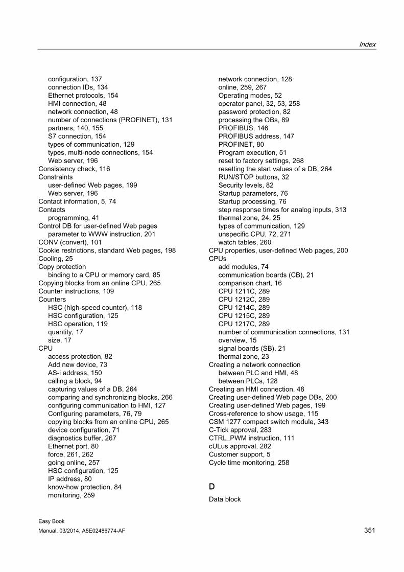
Index
Easy Book Manual, 03/2014, A5E02486774-AF 351
configuration, 137 connection IDs, 134 Ethernet protocols, 154 HMI connection, 48 network connection, 48 number of connections (PROFINET), 131 partners, 140, 155 S7 connection, 154 types of communication, 129 types, multi-node connections, 154 Web server, 196
Consistency check, 116 Constraints
user-defined Web pages, 199 Web server, 196
Contact information, 5, 74 Contacts
programming, 41 Control DB for user-defined Web pages
parameter to WWW instruction, 201 CONV (convert), 101 Cookie restrictions, standard Web pages, 198 Cooling, 25 Copy protection
binding to a CPU or memory card, 85 Copying blocks from an online CPU, 265 Counter instructions, 109 Counters
HSC (high-speed counter), 118 HSC configuration, 125 HSC operation, 119 quantity, 17 size, 17
CPU access protection, 82 Add new device, 73 AS-i address, 150 calling a block, 94 capturing values of a DB, 264 comparing and synchronizing blocks, 266 configuring communication to HMI, 127 Configuring parameters, 76, 79 copying blocks from an online CPU, 265 device configuration, 71 diagnostics buffer, 267 Ethernet port, 80 force, 261, 262 going online, 257 HSC configuration, 125 IP address, 80 know-how protection, 84 monitoring, 259
network connection, 128 online, 259, 267 Operating modes, 52 operator panel, 32, 53, 258 password protection, 82 processing the OBs, 89 PROFIBUS, 146 PROFIBUS address, 147 PROFINET, 80 Program execution, 51 reset to factory settings, 268 resetting the start values of a DB, 264 RUN/STOP buttons, 32 Security levels, 82 Startup parameters, 76 Startup processing, 76 step response times for analog inputs, 313 thermal zone, 24, 25 types of communication, 129 unspecific CPU, 72, 271 watch tables, 260
CPU properties, user-defined Web pages, 200 CPUs
add modules, 74 communication boards (CB), 21 comparison chart, 16 CPU 1211C, 289 CPU 1212C, 289 CPU 1214C, 289 CPU 1215C, 289 CPU 1217C, 289 number of communication connections, 131 overview, 15 signal boards (SB), 21 thermal zone, 23
Creating a network connection between PLC and HMI, 48 between PLCs, 128
Creating an HMI connection, 48 Creating user-defined Web page DBs, 200 Creating user-defined Web pages, 199 Cross-reference to show usage, 115 CSM 1277 compact switch module, 343 C-Tick approval, 283 CTRL_PWM instruction, 111 cULus approval, 282 Customer support, 5 Cycle time monitoring, 258
D Data block
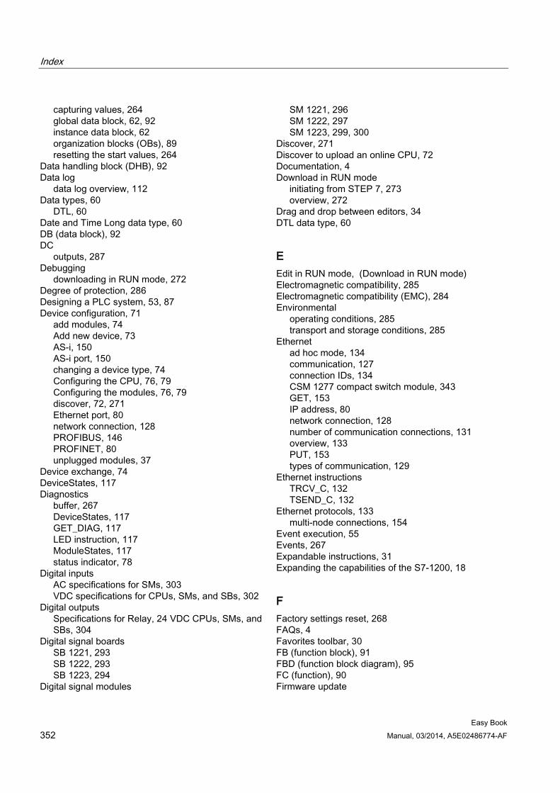
Index
Easy Book 352 Manual, 03/2014, A5E02486774-AF
capturing values, 264 global data block, 62, 92 instance data block, 62 organization blocks (OBs), 89 resetting the start values, 264
Data handling block (DHB), 92 Data log
data log overview, 112 Data types, 60
DTL, 60 Date and Time Long data type, 60 DB (data block), 92 DC
outputs, 287 Debugging
downloading in RUN mode, 272 Degree of protection, 286 Designing a PLC system, 53, 87 Device configuration, 71
add modules, 74 Add new device, 73 AS-i, 150 AS-i port, 150 changing a device type, 74 Configuring the CPU, 76, 79 Configuring the modules, 76, 79 discover, 72, 271 Ethernet port, 80 network connection, 128 PROFIBUS, 146 PROFINET, 80 unplugged modules, 37
Device exchange, 74 DeviceStates, 117 Diagnostics
buffer, 267 DeviceStates, 117 GET_DIAG, 117 LED instruction, 117 ModuleStates, 117 status indicator, 78
Digital inputs AC specifications for SMs, 303 VDC specifications for CPUs, SMs, and SBs, 302
Digital outputs Specifications for Relay, 24 VDC CPUs, SMs, and SBs, 304
Digital signal boards SB 1221, 293 SB 1222, 293 SB 1223, 294
Digital signal modules
SM 1221, 296 SM 1222, 297 SM 1223, 299, 300
Discover, 271 Discover to upload an online CPU, 72 Documentation, 4 Download in RUN mode
initiating from STEP 7, 273 overview, 272
Drag and drop between editors, 34 DTL data type, 60
E Edit in RUN mode, (Download in RUN mode) Electromagnetic compatibility, 285 Electromagnetic compatibility (EMC), 284 Environmental
operating conditions, 285 transport and storage conditions, 285
Ethernet ad hoc mode, 134 communication, 127 connection IDs, 134 CSM 1277 compact switch module, 343 GET, 153 IP address, 80 network connection, 128 number of communication connections, 131 overview, 133 PUT, 153 types of communication, 129
Ethernet instructions TRCV_C, 132 TSEND_C, 132
Ethernet protocols, 133 multi-node connections, 154
Event execution, 55 Events, 267 Expandable instructions, 31 Expanding the capabilities of the S7-1200, 18
F Factory settings reset, 268 FAQs, 4 Favorites toolbar, 30 FB (function block), 91 FBD (function block diagram), 95 FC (function), 90 Firmware update
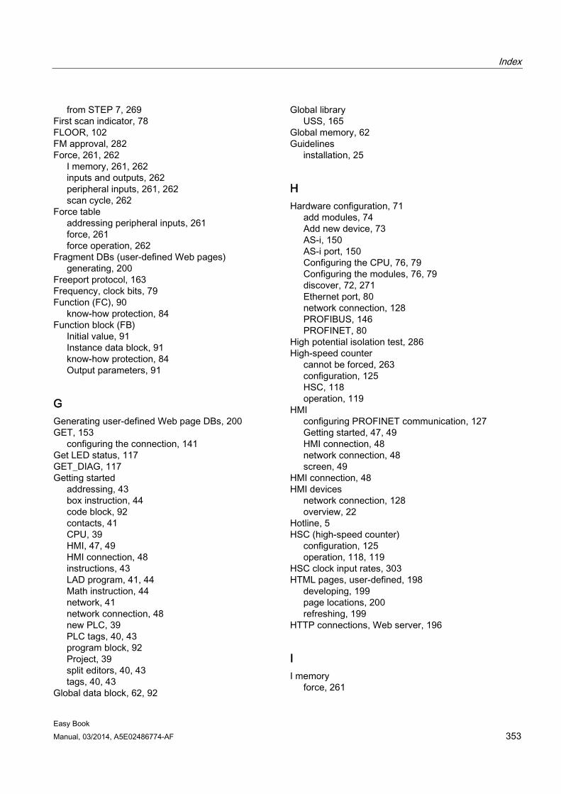
Index
Easy Book Manual, 03/2014, A5E02486774-AF 353
from STEP 7, 269 First scan indicator, 78 FLOOR, 102 FM approval, 282 Force, 261, 262
I memory, 261, 262 inputs and outputs, 262 peripheral inputs, 261, 262 scan cycle, 262
Force table addressing peripheral inputs, 261 force, 261 force operation, 262
Fragment DBs (user-defined Web pages) generating, 200
Freeport protocol, 163 Frequency, clock bits, 79 Function (FC), 90
know-how protection, 84 Function block (FB)
Initial value, 91 Instance data block, 91 know-how protection, 84 Output parameters, 91
G Generating user-defined Web page DBs, 200 GET, 153
configuring the connection, 141 Get LED status, 117 GET_DIAG, 117 Getting started
addressing, 43 box instruction, 44 code block, 92 contacts, 41 CPU, 39 HMI, 47, 49 HMI connection, 48 instructions, 43 LAD program, 41, 44 Math instruction, 44 network, 41 network connection, 48 new PLC, 39 PLC tags, 40, 43 program block, 92 Project, 39 split editors, 40, 43 tags, 40, 43
Global data block, 62, 92
Global library USS, 165
Global memory, 62 Guidelines
installation, 25
H Hardware configuration, 71
add modules, 74 Add new device, 73 AS-i, 150 AS-i port, 150 Configuring the CPU, 76, 79 Configuring the modules, 76, 79 discover, 72, 271 Ethernet port, 80 network connection, 128 PROFIBUS, 146 PROFINET, 80
High potential isolation test, 286 High-speed counter
cannot be forced, 263 configuration, 125 HSC, 118 operation, 119
HMI configuring PROFINET communication, 127 Getting started, 47, 49 HMI connection, 48 network connection, 48 screen, 49
HMI connection, 48 HMI devices
network connection, 128 overview, 22
Hotline, 5 HSC (high-speed counter)
configuration, 125 operation, 118, 119
HSC clock input rates, 303 HTML pages, user-defined, 198
developing, 199 page locations, 200 refreshing, 199
HTTP connections, Web server, 196
I I memory
force, 261
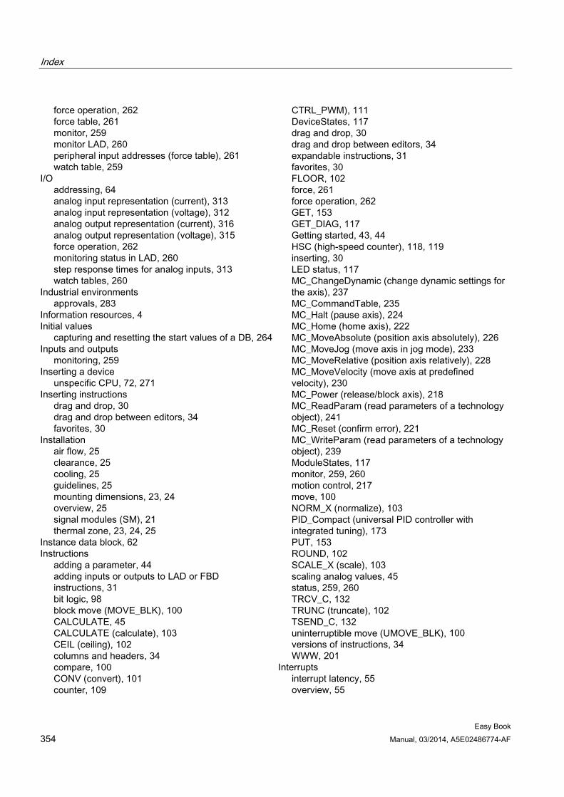
Index
Easy Book 354 Manual, 03/2014, A5E02486774-AF
force operation, 262 force table, 261 monitor, 259 monitor LAD, 260 peripheral input addresses (force table), 261 watch table, 259
I/O addressing, 64 analog input representation (current), 313 analog input representation (voltage), 312 analog output representation (current), 316 analog output representation (voltage), 315 force operation, 262 monitoring status in LAD, 260 step response times for analog inputs, 313 watch tables, 260
Industrial environments approvals, 283
Information resources, 4 Initial values
capturing and resetting the start values of a DB, 264 Inputs and outputs
monitoring, 259 Inserting a device
unspecific CPU, 72, 271 Inserting instructions
drag and drop, 30 drag and drop between editors, 34 favorites, 30
Installation air flow, 25 clearance, 25 cooling, 25 guidelines, 25 mounting dimensions, 23, 24 overview, 25 signal modules (SM), 21 thermal zone, 23, 24, 25
Instance data block, 62 Instructions
adding a parameter, 44 adding inputs or outputs to LAD or FBD instructions, 31 bit logic, 98 block move (MOVE_BLK), 100 CALCULATE, 45 CALCULATE (calculate), 103 CEIL (ceiling), 102 columns and headers, 34 compare, 100 CONV (convert), 101 counter, 109
CTRL_PWM), 111 DeviceStates, 117 drag and drop, 30 drag and drop between editors, 34 expandable instructions, 31 favorites, 30 FLOOR, 102 force, 261 force operation, 262 GET, 153 GET_DIAG, 117 Getting started, 43, 44 HSC (high-speed counter), 118, 119 inserting, 30 LED status, 117 MC_ChangeDynamic (change dynamic settings for the axis), 237 MC_CommandTable, 235 MC_Halt (pause axis), 224 MC_Home (home axis), 222 MC_MoveAbsolute (position axis absolutely), 226 MC_MoveJog (move axis in jog mode), 233 MC_MoveRelative (position axis relatively), 228 MC_MoveVelocity (move axis at predefined velocity), 230 MC_Power (release/block axis), 218 MC_ReadParam (read parameters of a technology object), 241 MC_Reset (confirm error), 221 MC_WriteParam (read parameters of a technology object), 239 ModuleStates, 117 monitor, 259, 260 motion control, 217 move, 100 NORM_X (normalize), 103 PID_Compact (universal PID controller with integrated tuning), 173 PUT, 153 ROUND, 102 SCALE_X (scale), 103 scaling analog values, 45 status, 259, 260 TRCV_C, 132 TRUNC (truncate), 102 TSEND_C, 132 uninterruptible move (UMOVE_BLK), 100 versions of instructions, 34 WWW, 201
Interrupts interrupt latency, 55 overview, 55
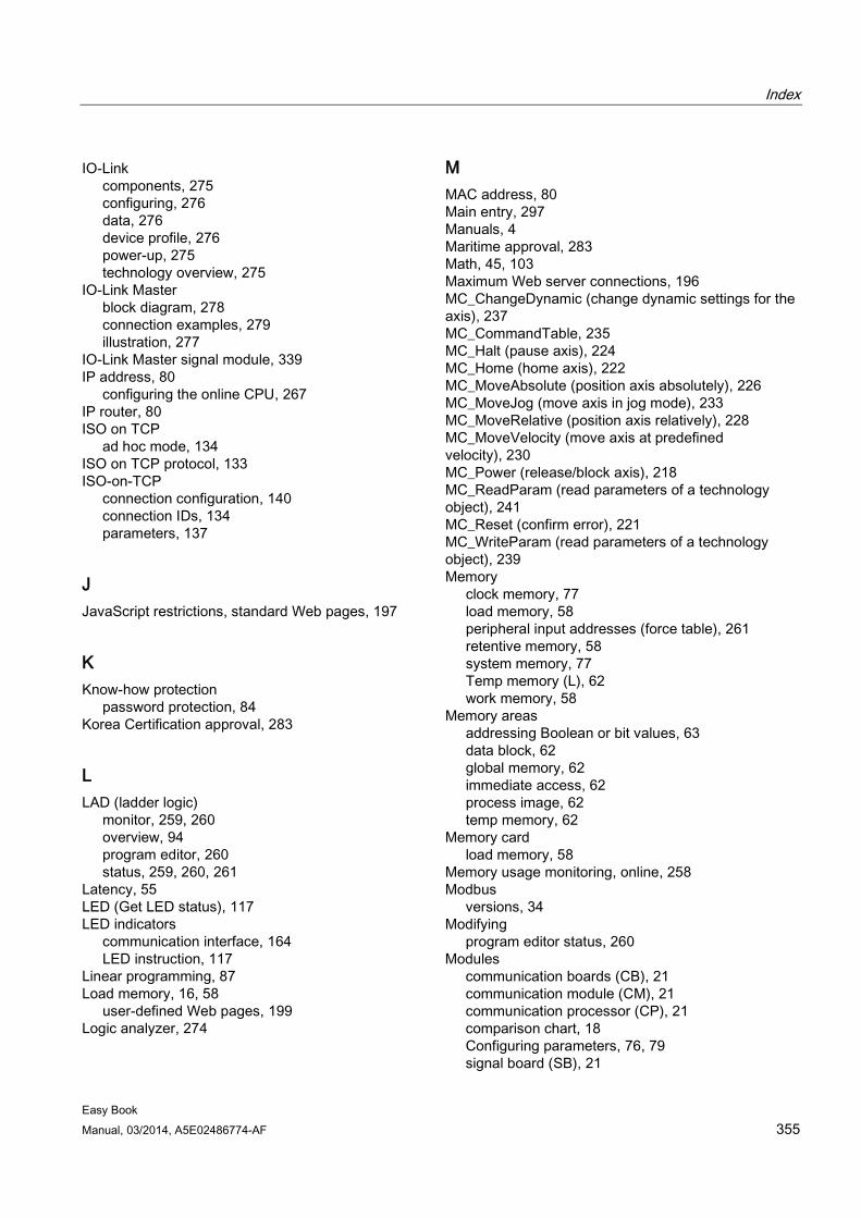
Index
Easy Book Manual, 03/2014, A5E02486774-AF 355
IO-Link components, 275 configuring, 276 data, 276 device profile, 276 power-up, 275 technology overview, 275
IO-Link Master block diagram, 278 connection examples, 279 illustration, 277
IO-Link Master signal module, 339 IP address, 80
configuring the online CPU, 267 IP router, 80 ISO on TCP
ad hoc mode, 134 ISO on TCP protocol, 133 ISO-on-TCP
connection configuration, 140 connection IDs, 134 parameters, 137
J JavaScript restrictions, standard Web pages, 197
K Know-how protection
password protection, 84 Korea Certification approval, 283
L LAD (ladder logic)
monitor, 259, 260 overview, 94 program editor, 260 status, 259, 260, 261
Latency, 55 LED (Get LED status), 117 LED indicators
communication interface, 164 LED instruction, 117
Linear programming, 87 Load memory, 16, 58
user-defined Web pages, 199 Logic analyzer, 274
M MAC address, 80 Main entry, 297 Manuals, 4 Maritime approval, 283 Math, 45, 103 Maximum Web server connections, 196 MC_ChangeDynamic (change dynamic settings for the axis), 237 MC_CommandTable, 235 MC_Halt (pause axis), 224 MC_Home (home axis), 222 MC_MoveAbsolute (position axis absolutely), 226 MC_MoveJog (move axis in jog mode), 233 MC_MoveRelative (position axis relatively), 228 MC_MoveVelocity (move axis at predefined velocity), 230 MC_Power (release/block axis), 218 MC_ReadParam (read parameters of a technology object), 241 MC_Reset (confirm error), 221 MC_WriteParam (read parameters of a technology object), 239 Memory
clock memory, 77 load memory, 58 peripheral input addresses (force table), 261 retentive memory, 58 system memory, 77 Temp memory (L), 62 work memory, 58
Memory areas addressing Boolean or bit values, 63 data block, 62 global memory, 62 immediate access, 62 process image, 62 temp memory, 62
Memory card load memory, 58
Memory usage monitoring, online, 258 Modbus
versions, 34 Modifying
program editor status, 260 Modules
communication boards (CB), 21 communication module (CM), 21 communication processor (CP), 21 comparison chart, 18 Configuring parameters, 76, 79 signal board (SB), 21
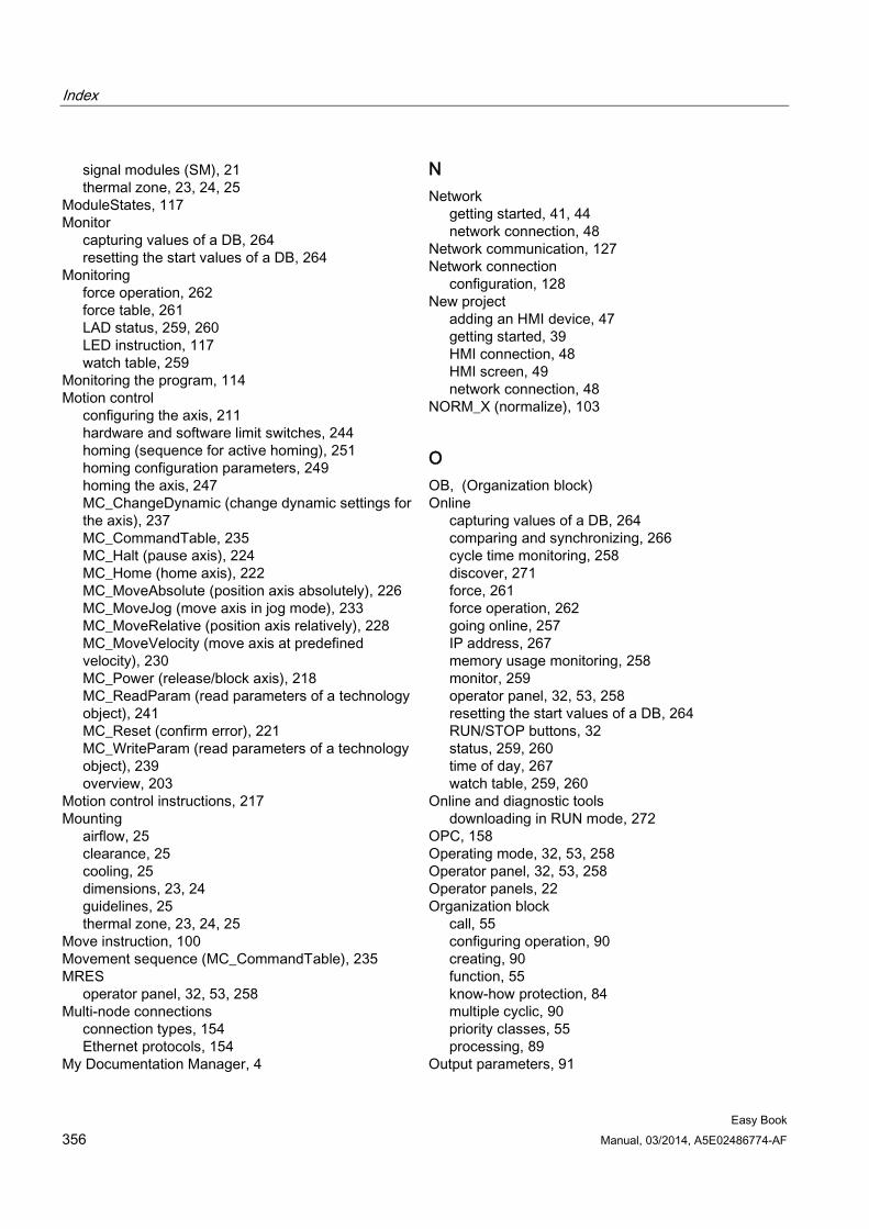
Index
Easy Book 356 Manual, 03/2014, A5E02486774-AF
signal modules (SM), 21 thermal zone, 23, 24, 25
ModuleStates, 117 Monitor
capturing values of a DB, 264 resetting the start values of a DB, 264
Monitoring force operation, 262 force table, 261 LAD status, 259, 260 LED instruction, 117 watch table, 259
Monitoring the program, 114 Motion control
configuring the axis, 211 hardware and software limit switches, 244 homing (sequence for active homing), 251 homing configuration parameters, 249 homing the axis, 247 MC_ChangeDynamic (change dynamic settings for the axis), 237 MC_CommandTable, 235 MC_Halt (pause axis), 224 MC_Home (home axis), 222 MC_MoveAbsolute (position axis absolutely), 226 MC_MoveJog (move axis in jog mode), 233 MC_MoveRelative (position axis relatively), 228 MC_MoveVelocity (move axis at predefined velocity), 230 MC_Power (release/block axis), 218 MC_ReadParam (read parameters of a technology object), 241 MC_Reset (confirm error), 221 MC_WriteParam (read parameters of a technology object), 239 overview, 203
Motion control instructions, 217 Mounting
airflow, 25 clearance, 25 cooling, 25 dimensions, 23, 24 guidelines, 25 thermal zone, 23, 24, 25
Move instruction, 100 Movement sequence (MC_CommandTable), 235 MRES
operator panel, 32, 53, 258 Multi-node connections
connection types, 154 Ethernet protocols, 154
My Documentation Manager, 4
N Network
getting started, 41, 44 network connection, 48
Network communication, 127 Network connection
configuration, 128 New project
adding an HMI device, 47 getting started, 39 HMI connection, 48 HMI screen, 49 network connection, 48
NORM_X (normalize), 103
O OB, (Organization block) Online
capturing values of a DB, 264 comparing and synchronizing, 266 cycle time monitoring, 258 discover, 271 force, 261 force operation, 262 going online, 257 IP address, 267 memory usage monitoring, 258 monitor, 259 operator panel, 32, 53, 258 resetting the start values of a DB, 264 RUN/STOP buttons, 32 status, 259, 260 time of day, 267 watch table, 259, 260
Online and diagnostic tools downloading in RUN mode, 272
OPC, 158 Operating mode, 32, 53, 258 Operator panel, 32, 53, 258 Operator panels, 22 Organization block
call, 55 configuring operation, 90 creating, 90 function, 55 know-how protection, 84 multiple cyclic, 90 priority classes, 55 processing, 89
Output parameters, 91
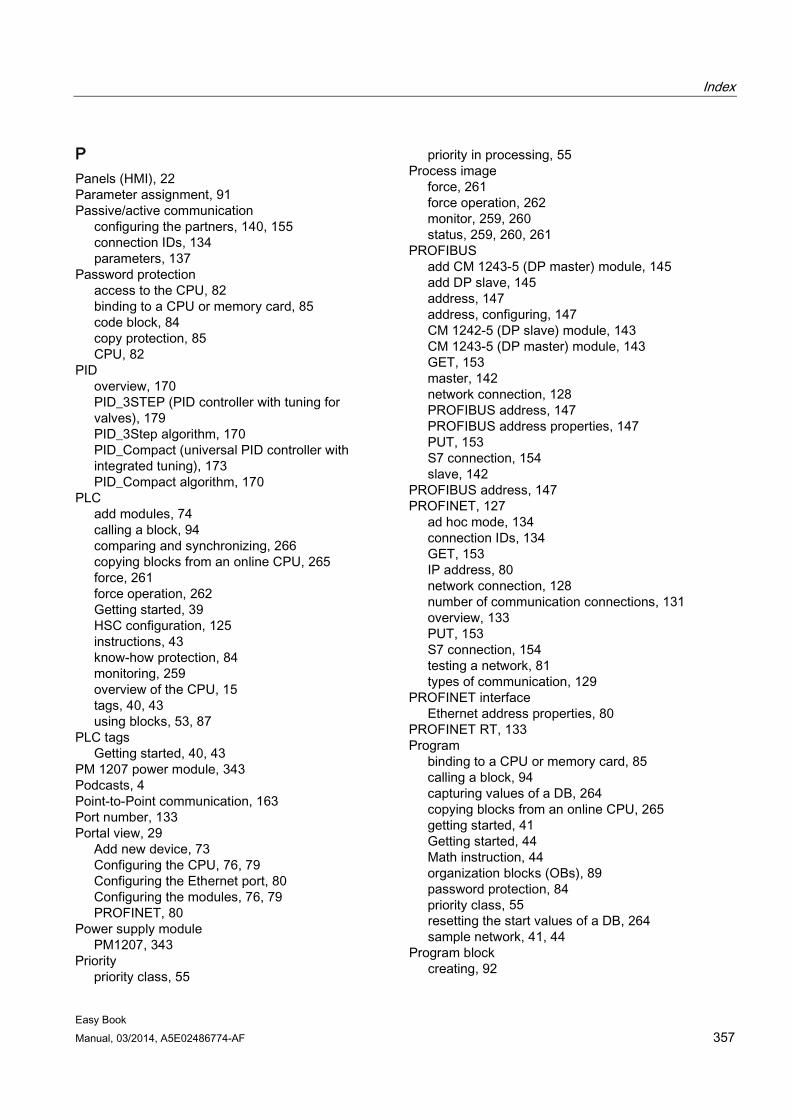
Index
Easy Book Manual, 03/2014, A5E02486774-AF 357
P Panels (HMI), 22 Parameter assignment, 91 Passive/active communication
configuring the partners, 140, 155 connection IDs, 134 parameters, 137
Password protection access to the CPU, 82 binding to a CPU or memory card, 85 code block, 84 copy protection, 85 CPU, 82
PID overview, 170 PID_3STEP (PID controller with tuning for valves), 179 PID_3Step algorithm, 170 PID_Compact (universal PID controller with integrated tuning), 173 PID_Compact algorithm, 170
PLC add modules, 74 calling a block, 94 comparing and synchronizing, 266 copying blocks from an online CPU, 265 force, 261 force operation, 262 Getting started, 39 HSC configuration, 125 instructions, 43 know-how protection, 84 monitoring, 259 overview of the CPU, 15 tags, 40, 43 using blocks, 53, 87
PLC tags Getting started, 40, 43
PM 1207 power module, 343 Podcasts, 4 Point-to-Point communication, 163 Port number, 133 Portal view, 29
Add new device, 73 Configuring the CPU, 76, 79 Configuring the Ethernet port, 80 Configuring the modules, 76, 79 PROFINET, 80
Power supply module PM1207, 343
Priority priority class, 55
priority in processing, 55 Process image
force, 261 force operation, 262 monitor, 259, 260 status, 259, 260, 261
PROFIBUS add CM 1243-5 (DP master) module, 145 add DP slave, 145 address, 147 address, configuring, 147 CM 1242-5 (DP slave) module, 143 CM 1243-5 (DP master) module, 143 GET, 153 master, 142 network connection, 128 PROFIBUS address, 147 PROFIBUS address properties, 147 PUT, 153 S7 connection, 154 slave, 142
PROFIBUS address, 147 PROFINET, 127
ad hoc mode, 134 connection IDs, 134 GET, 153 IP address, 80 network connection, 128 number of communication connections, 131 overview, 133 PUT, 153 S7 connection, 154 testing a network, 81 types of communication, 129
PROFINET interface Ethernet address properties, 80
PROFINET RT, 133 Program
binding to a CPU or memory card, 85 calling a block, 94 capturing values of a DB, 264 copying blocks from an online CPU, 265 getting started, 41 Getting started, 44 Math instruction, 44 organization blocks (OBs), 89 password protection, 84 priority class, 55 resetting the start values of a DB, 264 sample network, 41, 44
Program block creating, 92
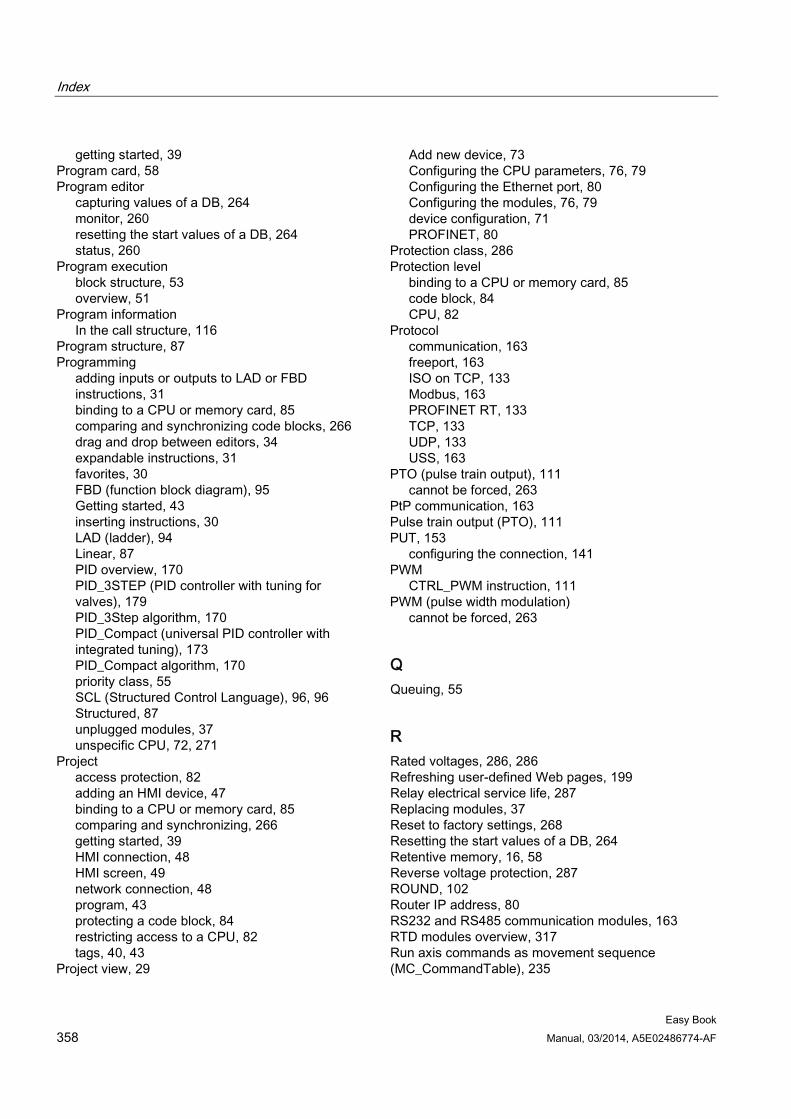
Index
Easy Book 358 Manual, 03/2014, A5E02486774-AF
getting started, 39 Program card, 58 Program editor
capturing values of a DB, 264 monitor, 260 resetting the start values of a DB, 264 status, 260
Program execution block structure, 53 overview, 51
Program information In the call structure, 116
Program structure, 87 Programming
adding inputs or outputs to LAD or FBD instructions, 31 binding to a CPU or memory card, 85 comparing and synchronizing code blocks, 266 drag and drop between editors, 34 expandable instructions, 31 favorites, 30 FBD (function block diagram), 95 Getting started, 43 inserting instructions, 30 LAD (ladder), 94 Linear, 87 PID overview, 170 PID_3STEP (PID controller with tuning for valves), 179 PID_3Step algorithm, 170 PID_Compact (universal PID controller with integrated tuning), 173 PID_Compact algorithm, 170 priority class, 55 SCL (Structured Control Language), 96, 96 Structured, 87 unplugged modules, 37 unspecific CPU, 72, 271
Project access protection, 82 adding an HMI device, 47 binding to a CPU or memory card, 85 comparing and synchronizing, 266 getting started, 39 HMI connection, 48 HMI screen, 49 network connection, 48 program, 43 protecting a code block, 84 restricting access to a CPU, 82 tags, 40, 43
Project view, 29
Add new device, 73 Configuring the CPU parameters, 76, 79 Configuring the Ethernet port, 80 Configuring the modules, 76, 79 device configuration, 71 PROFINET, 80
Protection class, 286 Protection level
binding to a CPU or memory card, 85 code block, 84 CPU, 82
Protocol communication, 163 freeport, 163 ISO on TCP, 133 Modbus, 163 PROFINET RT, 133 TCP, 133 UDP, 133 USS, 163
PTO (pulse train output), 111 cannot be forced, 263
PtP communication, 163 Pulse train output (PTO), 111 PUT, 153
configuring the connection, 141 PWM
CTRL_PWM instruction, 111 PWM (pulse width modulation)
cannot be forced, 263
Q Queuing, 55
R Rated voltages, 286, 286 Refreshing user-defined Web pages, 199 Relay electrical service life, 287 Replacing modules, 37 Reset to factory settings, 268 Resetting the start values of a DB, 264 Retentive memory, 16, 58 Reverse voltage protection, 287 ROUND, 102 Router IP address, 80 RS232 and RS485 communication modules, 163 RTD modules overview, 317 Run axis commands as movement sequence (MC_CommandTable), 235
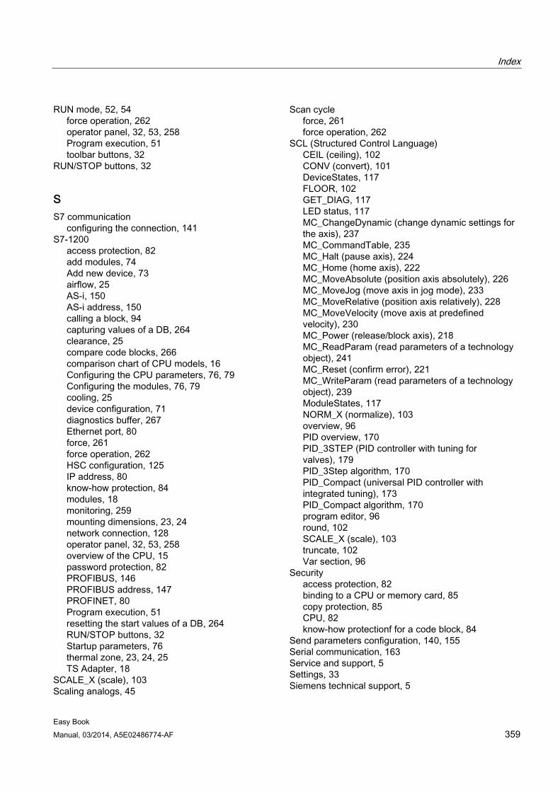
Index
Easy Book Manual, 03/2014, A5E02486774-AF 359
RUN mode, 52, 54 force operation, 262 operator panel, 32, 53, 258 Program execution, 51 toolbar buttons, 32
RUN/STOP buttons, 32
S S7 communication
configuring the connection, 141 S7-1200
access protection, 82 add modules, 74 Add new device, 73 airflow, 25 AS-i, 150 AS-i address, 150 calling a block, 94 capturing values of a DB, 264 clearance, 25 compare code blocks, 266 comparison chart of CPU models, 16 Configuring the CPU parameters, 76, 79 Configuring the modules, 76, 79 cooling, 25 device configuration, 71 diagnostics buffer, 267 Ethernet port, 80 force, 261 force operation, 262 HSC configuration, 125 IP address, 80 know-how protection, 84 modules, 18 monitoring, 259 mounting dimensions, 23, 24 network connection, 128 operator panel, 32, 53, 258 overview of the CPU, 15 password protection, 82 PROFIBUS, 146 PROFIBUS address, 147 PROFINET, 80 Program execution, 51 resetting the start values of a DB, 264 RUN/STOP buttons, 32 Startup parameters, 76 thermal zone, 23, 24, 25 TS Adapter, 18
SCALE_X (scale), 103 Scaling analogs, 45
Scan cycle force, 261 force operation, 262
SCL (Structured Control Language) CEIL (ceiling), 102 CONV (convert), 101 DeviceStates, 117 FLOOR, 102 GET_DIAG, 117 LED status, 117 MC_ChangeDynamic (change dynamic settings for the axis), 237 MC_CommandTable, 235 MC_Halt (pause axis), 224 MC_Home (home axis), 222 MC_MoveAbsolute (position axis absolutely), 226 MC_MoveJog (move axis in jog mode), 233 MC_MoveRelative (position axis relatively), 228 MC_MoveVelocity (move axis at predefined velocity), 230 MC_Power (release/block axis), 218 MC_ReadParam (read parameters of a technology object), 241 MC_Reset (confirm error), 221 MC_WriteParam (read parameters of a technology object), 239 ModuleStates, 117 NORM_X (normalize), 103 overview, 96 PID overview, 170 PID_3STEP (PID controller with tuning for valves), 179 PID_3Step algorithm, 170 PID_Compact (universal PID controller with integrated tuning), 173 PID_Compact algorithm, 170 program editor, 96 round, 102 SCALE_X (scale), 103 truncate, 102 Var section, 96
Security access protection, 82 binding to a CPU or memory card, 85 copy protection, 85 CPU, 82 know-how protectionf for a code block, 84
Send parameters configuration, 140, 155 Serial communication, 163 Service and support, 5 Settings, 33 Siemens technical support, 5
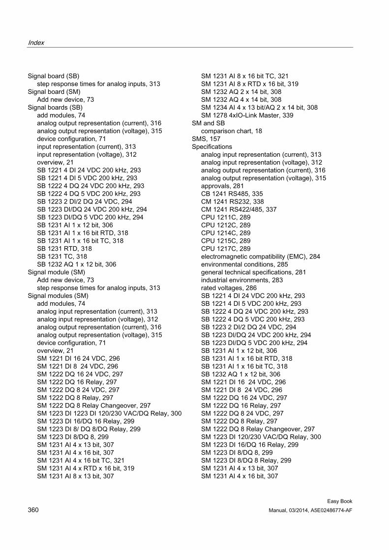
Index
Easy Book 360 Manual, 03/2014, A5E02486774-AF
Signal board (SB) step response times for analog inputs, 313
Signal board (SM) Add new device, 73
Signal boards (SB) add modules, 74 analog output representation (current), 316 analog output representation (voltage), 315 device configuration, 71 input representation (current), 313 input representation (voltage), 312 overview, 21 SB 1221 4 DI 24 VDC 200 kHz, 293 SB 1221 4 DI 5 VDC 200 kHz, 293 SB 1222 4 DQ 24 VDC 200 kHz, 293 SB 1222 4 DQ 5 VDC 200 kHz, 293 SB 1223 2 DI/2 DQ 24 VDC, 294 SB 1223 DI/DQ 24 VDC 200 kHz, 294 SB 1223 DI/DQ 5 VDC 200 kHz, 294 SB 1231 AI 1 x 12 bit, 306 SB 1231 AI 1 x 16 bit RTD, 318 SB 1231 AI 1 x 16 bit TC, 318 SB 1231 RTD, 318 SB 1231 TC, 318 SB 1232 AQ 1 x 12 bit, 306
Signal module (SM) Add new device, 73 step response times for analog inputs, 313
Signal modules (SM) add modules, 74 analog input representation (current), 313 analog input representation (voltage), 312 analog output representation (current), 316 analog output representation (voltage), 315 device configuration, 71 overview, 21 SM 1221 DI 16 24 VDC, 296 SM 1221 DI 8 24 VDC, 296 SM 1222 DQ 16 24 VDC, 297 SM 1222 DQ 16 Relay, 297 SM 1222 DQ 8 24 VDC, 297 SM 1222 DQ 8 Relay, 297 SM 1222 DQ 8 Relay Changeover, 297 SM 1223 DI 1223 DI 120/230 VAC/DQ Relay, 300 SM 1223 DI 16/DQ 16 Relay, 299 SM 1223 DI 8/ DQ 8/DQ Relay, 299 SM 1223 DI 8/DQ 8, 299 SM 1231 AI 4 x 13 bit, 307 SM 1231 AI 4 x 16 bit, 307 SM 1231 AI 4 x 16 bit TC, 321 SM 1231 AI 4 x RTD x 16 bit, 319 SM 1231 AI 8 x 13 bit, 307
SM 1231 AI 8 x 16 bit TC, 321 SM 1231 AI 8 x RTD x 16 bit, 319 SM 1232 AQ 2 x 14 bit, 308 SM 1232 AQ 4 x 14 bit, 308 SM 1234 AI 4 x 13 bit/AQ 2 x 14 bit, 308 SM 1278 4xIO-Link Master, 339
SM and SB comparison chart, 18
SMS, 157 Specifications
analog input representation (current), 313 analog input representation (voltage), 312 analog output representation (current), 316 analog output representation (voltage), 315 approvals, 281 CB 1241 RS485, 335 CM 1241 RS232, 338 CM 1241 RS422/485, 337 CPU 1211C, 289 CPU 1212C, 289 CPU 1214C, 289 CPU 1215C, 289 CPU 1217C, 289 electromagnetic compatibility (EMC), 284 environmental conditions, 285 general technical specifications, 281 industrial environments, 283 rated voltages, 286 SB 1221 4 DI 24 VDC 200 kHz, 293 SB 1221 4 DI 5 VDC 200 kHz, 293 SB 1222 4 DQ 24 VDC 200 kHz, 293 SB 1222 4 DQ 5 VDC 200 kHz, 293 SB 1223 2 DI/2 DQ 24 VDC, 294 SB 1223 DI/DQ 24 VDC 200 kHz, 294 SB 1223 DI/DQ 5 VDC 200 kHz, 294 SB 1231 AI 1 x 12 bit, 306 SB 1231 AI 1 x 16 bit RTD, 318 SB 1231 AI 1 x 16 bit TC, 318 SB 1232 AQ 1 x 12 bit, 306 SM 1221 DI 16 24 VDC, 296 SM 1221 DI 8 24 VDC, 296 SM 1222 DQ 16 24 VDC, 297 SM 1222 DQ 16 Relay, 297 SM 1222 DQ 8 24 VDC, 297 SM 1222 DQ 8 Relay, 297 SM 1222 DQ 8 Relay Changeover, 297 SM 1223 DI 120/230 VAC/DQ Relay, 300 SM 1223 DI 16/DQ 16 Relay, 299 SM 1223 DI 8/DQ 8, 299 SM 1223 DI 8/DQ 8 Relay, 299 SM 1231 AI 4 x 13 bit, 307 SM 1231 AI 4 x 16 bit, 307
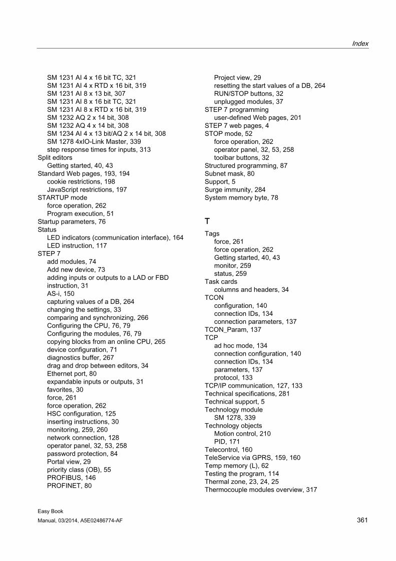
Index
Easy Book Manual, 03/2014, A5E02486774-AF 361
SM 1231 AI 4 x 16 bit TC, 321 SM 1231 AI 4 x RTD x 16 bit, 319 SM 1231 AI 8 x 13 bit, 307 SM 1231 AI 8 x 16 bit TC, 321 SM 1231 AI 8 x RTD x 16 bit, 319 SM 1232 AQ 2 x 14 bit, 308 SM 1232 AQ 4 x 14 bit, 308 SM 1234 AI 4 x 13 bit/AQ 2 x 14 bit, 308 SM 1278 4xIO-Link Master, 339 step response times for inputs, 313
Split editors Getting started, 40, 43
Standard Web pages, 193, 194 cookie restrictions, 198 JavaScript restrictions, 197
STARTUP mode force operation, 262 Program execution, 51
Startup parameters, 76 Status
LED indicators (communication interface), 164 LED instruction, 117
STEP 7 add modules, 74 Add new device, 73 adding inputs or outputs to a LAD or FBD instruction, 31 AS-i, 150 capturing values of a DB, 264 changing the settings, 33 comparing and synchronizing, 266 Configuring the CPU, 76, 79 Configuring the modules, 76, 79 copying blocks from an online CPU, 265 device configuration, 71 diagnostics buffer, 267 drag and drop between editors, 34 Ethernet port, 80 expandable inputs or outputs, 31 favorites, 30 force, 261 force operation, 262 HSC configuration, 125 inserting instructions, 30 monitoring, 259, 260 network connection, 128 operator panel, 32, 53, 258 password protection, 84 Portal view, 29 priority class (OB), 55 PROFIBUS, 146 PROFINET, 80
Project view, 29 resetting the start values of a DB, 264 RUN/STOP buttons, 32 unplugged modules, 37
STEP 7 programming user-defined Web pages, 201
STEP 7 web pages, 4 STOP mode, 52
force operation, 262 operator panel, 32, 53, 258 toolbar buttons, 32
Structured programming, 87 Subnet mask, 80 Support, 5 Surge immunity, 284 System memory byte, 78
T Tags
force, 261 force operation, 262 Getting started, 40, 43 monitor, 259 status, 259
Task cards columns and headers, 34
TCON configuration, 140 connection IDs, 134 connection parameters, 137
TCON_Param, 137 TCP
ad hoc mode, 134 connection configuration, 140 connection IDs, 134 parameters, 137 protocol, 133
TCP/IP communication, 127, 133 Technical specifications, 281 Technical support, 5 Technology module
SM 1278, 339 Technology objects
Motion control, 210 PID, 171
Telecontrol, 160 TeleService via GPRS, 159, 160 Temp memory (L), 62 Testing the program, 114 Thermal zone, 23, 24, 25 Thermocouple modules overview, 317
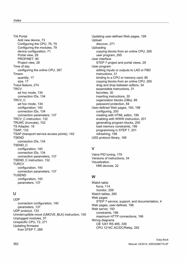
Index
Easy Book 362 Manual, 03/2014, A5E02486774-AF
TIA Portal Add new device, 73 Configuring the CPU, 76, 79 Configuring the modules, 79 device configuration, 71 Portal view, 29 PROFINET, 80 Project view, 29
Time of day configuring the online CPU, 267
Timers quantity, 17 size, 17
Trace feature, 274 TRCV
ad hoc mode, 134 connection IDs, 134
TRCV_C ad hoc mode, 134 configuration, 140 connection IDs, 134 connection parameters, 137
TRCV_C instruction, 132 TRUNC (truncate), 102 TS Adapter, 18 TSAP, 133 TSAP (transport service access points), 142 TSEND
connection IDs, 134 TSEND_C
configuration, 140 connection IDs, 134 connection parameters, 137
TSEND_C instruction, 132 TURCV
configuration, 140 connection parameters, 137
TUSEND configuration, 140 parameters, 137
U UDP
connection configuration, 140 parameters, 137
UDP protocol, 133 Uninterruptible move (UMOVE_BLK) instruction, 100 Unplugged modules, 37 Unspecific CPU, 72, 271 Updating firmware
from STEP 7, 269
Updating user-defined Web pages, 199 Upload
discover, 271 Uploading
copying blocks from an online CPU, 265 user program, 265
User interface STEP 7 project and portal views, 29
User program adding inputs or outputs to LAD or FBD instructions, 31 binding to a CPU or memory card, 85 copying blocks from an online CPU, 265 drag and drop between editors, 34 expandable instructions, 31 favorites, 30 inserting instructions, 30 organization blocks (OBs), 89 password protection, 84
User-defined Web pages, 193, 198 configuring, 200 creating with HTML editor, 199 enabling with WWW instruction, 201 generating program blocks, 200 load memory constraints, 199 programming in STEP 7, 201 refreshing, 199
USS protocol library, 165
V Valve PID tuning, 179 Versions of instructions, 34 Visualization
HMI devices, 22
W Watch table
force, 114 monitor, 259
Watch tables, 260 Web pages
STEP 7 service, support, and documentation, 4 Web pages, user-defined, 198 Web server, 193
constraints, 196 maximum HTTP connections, 196
Wiring diagrams CB 1241 RS 485, 336 CPU 1214C AC/DC/Relay, 292
Index
Easy Book Manual, 03/2014, A5E02486774-AF 363
CPU 1214C DC/DC/DC, 293 SB 1221 DI 4 200 kHz, 295 SB 1222 DQ 4 200 kHzl;, 295 SB 1223 DI 2/DQ 2 200 kHz, 295 SB 1231 AI 1 x 12 bit, 307 SB 1231 AI 1 x 16 bit RTD, 319 SB 1231 AI 1 x 16 bit TC, 319 SB 1232 AQ 1 x 12 bit, 307 SM 1221 DI 16 24 VDC, 297 SM 1221 DI 8 24 VDC, 297 SM 1222 DQ 16 24 VDC, 298 SM 1222 DQ 16 Relay, 298 SM 1223 DI 16 VDC / DQ 16 Relay, 300 SM 1223 DI 16 VDC/ DQ 16 24 VDC, 300 SM 1223 DI 8 120/230 VAC/DQ 8 Relay, 301 SM 1231 AI 8 x 13 bit, 309 SM 1231 RTD 4 x 16 bit, 321 SM 1231 RTD 8 x 16 bit, 321 SM 1232 AQ 4 x 13 bit, 309 SM 1234 AI 4 x 13 bit/AQ 2 x 14 bit, 309 SM 1278 IO-Link Master, 342
Wiring guidelines clearance for airflow and cooling, 25
Work memory, 16, 58 WWW, 201

Index
Easy Book 364 Manual, 03/2014, A5E02486774-AF


![[en-us] bosch-home.com/us/mybosch mybosch [en-us] Dishwasher](https://static.fdocuments.in/doc/165x107/615cc8afbe7e0d1e5a38c77e/en-us-bosch-homecomusmybosch-mybosch-en-us-dishwasher.jpg)