S7-200 Technical Specifications
78
391 Technical Specifications In This Chapter General Technical Specifications 392 ................................................... CPU Specifications 395 .............................................................. Digital Expansion Modules Specifications 404 ........................................... Analog Expansion Modules Specifications 411 ........................................... Thermocouple and RTD Expansion Modules Specifications 423 ............................ EM 277 PROFIBUS--DP Module Specifications 435 ...................................... EM 241 Modem Module Specifications 447 .............................................. EM 253 Position Module Specifications 449 ............................................. (CP 243--1) Ethernet Module Specifications 455 ......................................... (CP 243--1 IT) Internet Module Specifications 457 ........................................ (CP 243--2) AS--Interface Module Specifications 460 ...................................... Optional Cartridges 462 .............................................................. I/O Expansion Cable 463 ............................................................. RS-232/PPI Multi-Master Cable and USB/PPI Multi-Master Cable 464 ...................... Input Simulators 468 .................................................................
-
Upload
thuy-nguyen-xuan -
Category
Documents
-
view
311 -
download
11
Transcript of S7-200 Technical Specifications

391
Technical Specifications
In This ChapterGeneral Technical Specifications 392. . . . . . . . . . . . . . . . . . . . . . . . . . . . . . . . . . . . . . . . . . . . . . . . . . .
CPU Specifications 395. . . . . . . . . . . . . . . . . . . . . . . . . . . . . . . . . . . . . . . . . . . . . . . . . . . . . . . . . . . . . .
Digital Expansion Modules Specifications 404. . . . . . . . . . . . . . . . . . . . . . . . . . . . . . . . . . . . . . . . . . .
Analog Expansion Modules Specifications 411. . . . . . . . . . . . . . . . . . . . . . . . . . . . . . . . . . . . . . . . . . .
Thermocouple and RTD Expansion Modules Specifications 423. . . . . . . . . . . . . . . . . . . . . . . . . . . .
EM 277 PROFIBUS--DP Module Specifications 435. . . . . . . . . . . . . . . . . . . . . . . . . . . . . . . . . . . . . .
EM 241 Modem Module Specifications 447. . . . . . . . . . . . . . . . . . . . . . . . . . . . . . . . . . . . . . . . . . . . . .
EM 253 Position Module Specifications 449. . . . . . . . . . . . . . . . . . . . . . . . . . . . . . . . . . . . . . . . . . . . .
(CP 243--1) Ethernet Module Specifications 455. . . . . . . . . . . . . . . . . . . . . . . . . . . . . . . . . . . . . . . . .
(CP 243--1 IT) Internet Module Specifications 457. . . . . . . . . . . . . . . . . . . . . . . . . . . . . . . . . . . . . . . .
(CP 243--2) AS--Interface Module Specifications 460. . . . . . . . . . . . . . . . . . . . . . . . . . . . . . . . . . . . . .
Optional Cartridges 462. . . . . . . . . . . . . . . . . . . . . . . . . . . . . . . . . . . . . . . . . . . . . . . . . . . . . . . . . . . . . .
I/O Expansion Cable 463. . . . . . . . . . . . . . . . . . . . . . . . . . . . . . . . . . . . . . . . . . . . . . . . . . . . . . . . . . . . .
RS-232/PPI Multi-Master Cable and USB/PPI Multi-Master Cable 464. . . . . . . . . . . . . . . . . . . . . .
Input Simulators 468. . . . . . . . . . . . . . . . . . . . . . . . . . . . . . . . . . . . . . . . . . . . . . . . . . . . . . . . . . . . . . . . .

S7-200 Programmable Controller System Manual
392
General Technical Specifications
Standards ComplianceThe national and international standards listed below were used to determine appropriateperformance specifications and testing for the S7-200 family of products. Table A-1 defines thespecific adherence to these standards.
- European Community (CE) Low Voltage Directive 73/23/EECEN 61131--2: Programmable controllers -- Equipment requirements
- European Community (CE) EMC Directive 89/336/EEC
Electromagnetic emission standardEN 61000--6--3: residential, commercial, and light industryEN 61000--6--4: industrial environment
Electromagnetic immunity standardsEN 61000--6--2: industrial environment
- Underwriters Laboratories, Inc.: UL 508 Listed (Industrial Control Equipment),Registration number E75310
- Canadian Standards Association: CSA C22.2 Number 142 (Process Control Equipment)
- Factory Mutual Research: Class Number 3600, Class Number 3611, FM Class I, Division 2,Groups A, B, C, & D Hazardous Locations, T4A and Class I, Zone 2, IIC, T4.
- European Community (ATEX) Atmospheres Explosibles Directive 94/9/ECEN 60079--0 General requirementsEN 50020 Intrinsic safety ‘i’EN 60079--15 Type of protection ‘n’
ATEX Directive applies to CPUs and expansion modules with a rated voltage of 24 VDC. Itdoes not apply to modules with AC power systems or Relay outputs. Consult your localSiemens representative for a list of ATEX approved modules.
TipThe SIMATIC S7-200 series meets the CSA standard.
The cULus logo indicates that the S7-200 has been examined and certified by UnderwritersLaboratories (UL) to standards UL 508 and CSA 22.2 No. 142.
Maritime ApprovalsThe S7-200 products are periodicallysubmitted for special agency approvalsrelated to specific markets and applications.This table identifies the agency andcertificate number that the S7-200 productshave been approved for. Most S7-200products in this manual have beenapproved for these special agencyapprovals. Consult your local Siemensrepresentative if you need additionalinformation related to the latest listing ofexact approvals by part number.
Agency Certificate Number
Lloyds Register of Shipping(LRS)
99 / 20018(E1)
American Bureau of Shipping(ABS)
01--HG20020--PDA
Germanischer Lloyd (GL) 12 045 -- 98 HH
Det Norske Veritas (DNV) A--8862
Bureau Veritas (BV) 09051 / B0BV
Nippon Kaiji Kyokai (NK) A--534
Polski Rejestr TE/1246/883241/99
Technical Specifications Appendix A
393
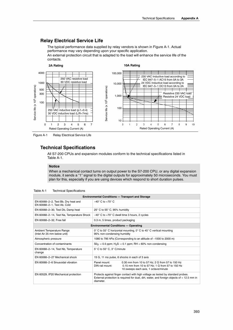
Relay Electrical Service LifeThe typical performance data supplied by relay vendors is shown in Figure A-1. Actualperformance may vary depending upon your specific application.An external protection circuit that is adapted to the load will enhance the service life of thecontacts.
100,000
10,000
1,000
100
10
Rated Operating Current (A)
230 VAC Inductive load according toIEC 947--5--1 AC15 from 0A to 3A24 VDC Inductive load according toIEC 947--5--1 DC13 from 0A to 2A
Resistive 230 VAC loadResistive 24 VDC load
0 1 2 3 4 5 6 7
4000
250 VAC resistive load30 VDC resistive load
250 VAC inductive load (p.f.=0.4)30 VDC inductive load (L/R=7ms)
Rated Operating Current (A)
Service
life(x10
3operations)
1000
500
300
100Service
life(x10
3operations)
2A Rating 10A Rating
Figure A-1 Relay Electrical Service Life
Technical SpecificationsAll S7-200 CPUs and expansion modules conform to the technical specifications listed inTable A-1.
NoticeWhen a mechanical contact turns on output power to the S7-200 CPU, or any digital expansionmodule, it sends a “1” signal to the digital outputs for approximately 50 microseconds. You mustplan for this, especially if you are using devices which respond to short duration pulses.
Table A-1 Technical Specifications
Environmental Conditions — Transport and Storage
EN 60068--2--2, Test Bb, Dry heat andEN 60068--2--1, Test Ab, Cold
--40° C to +70° C
EN 60068--2--30, Test Db, Damp heat 25° C to 55° C, 95% humidity
EN 60068--2--14, Test Na, Temperature Shock --40° C to +70° C dwell time 3 hours, 2 cycles
EN 60068--2--32, Free fall 0.3 m, 5 times, product packaging
Environmental Conditions — Operating
Ambient Temperature Range(Inlet Air 25 mm below unit)
0° C to 55° C horizontal mounting, 0° C to 45° C vertical mounting95% non-condensing humidity
Atmospheric pressure 1080 to 795 hPa (Corresponding to an altitude of --1000 to 2000 m)
Concentration of contaminants S02: < 0.5 ppm; H2S: < 0.1 ppm; RH < 60% non-condensing
EN 60068--2--14, Test Nb, Temperaturechange
5° C to 55° C, 3° C/minute
EN 60068--2--27 Mechanical shock 15 G, 11 ms pulse, 6 shocks in each of 3 axis
EN 60068--2--6 Sinusoidal vibration Panel mount: 0.30 mm from 10 to 57 Hz; 2 G from 57 to 150 HzDIN rail mount: 0.15 mm from 10 to 57 Hz; 1 G from 57 to 150 Hz
10 sweeps each axis, 1 octave/minute
EN 60529, IP20 Mechanical protection Protects against finger contact with high voltage as tested by standard probes.External protection is required for dust, dirt, water, and foreign objects of < 12.5 mm indiameter.

S7-200 Programmable Controller System Manual
394
Table A-1 Technical Specifications, continued
Electromagnetic Compatibility — Immunity per EN61000--6--21
EN 61000--4--2 Electrostatic discharge 8 kV air discharge to all surfaces and communications port,4 kV contact discharge to exposed conductive surfaces
EN 61000--4--3 Radiated electromagnetic field 10 V/m, 80--1000 MHz, 1.4--2.0 GHz and 2.0--2.7 GHz, 80% AM at 1kHz
EN 61000--4--4 Fast transient bursts 2 kV, 5 kHz with coupling network to AC and DC system power2 kV, 5 kHz with coupling clamp to I/O1 kV, 5 kHz with coupling clamp to communications
EN 61000--4--5 Surge immunity Power supply: 2 kV asymmetrical, 1 kV symmetricalI/O 1 kV symmetrical(24 VDC circuits require external surge protection)
EN 61000--4--6 Conducted disturbances 0.15 to 80 MHz, 10 V RMS, 80% AM at 1kHz
EN 61000--4--11 Voltage dips, shortinterruptions and voltage variations
>95% reduction for 8.3 ms, 83 ms, 833 ms, and 4167 ms
VDE 0160 Non-periodic overvoltage At 85 VAC line, 90° phase angle, apply 390 V peak, 1.3 ms pulseAt 180 VAC line, 90° phase angle, apply 750 V peak, 1.3 ms pulse
Electromagnetic Compatibility — Conducted and Radiated Emissions per EN 61000--6--32 and EN 61000--6--4
EN 55011, Class A, Group 1, conducted1
0.15 MHz to 0.5 MHz0.5 MHz to 5 MHz5 MHz to 30 MHz
< 79 dB (µV) Quasi-peak; < 66 dB (µV) Average< 73 dB (µV) Quasi-peak; < 60 dB (µV) Average< 73 dB (µV) Quasi-peak; < 60 dB (µV) Average
EN 55011, Class A, Group 1, radiated1
30 MHz to 230 MHz230 MHz to 1 GHz
40 dB (µV/m) Quasi-peak; measured at 10 m47 dB (µV/m) Quasi-peak; measured at 10 m
EN 55011, Class B, Group 1, conducted2
0.15 to 0.5 MHz
0.5 MHz to 5 MHz5 MHz to 30 MHz
< 66 dB (µV) Quasi-peak decreasing with log frequency to 56 dB (µV);< 56 dB (µV) Average decreasing with log frequency to 46 dB (µV)< 56 dB (µV) Quasi-peak; < 46 dB (µV) Average< 60 dB (µV) Quasi-peak; < 50 dB (µV) Average
EN 55011, Class B, Group 1, radiated2
30 MHz to 230 kHz230 MHz to 1 GHz
30 dB (µV/m) Quasi-peak; measured at 10 m37 dB (µV/m) Quasi-peak; measured at 10 m
High Potential Isolation Test
24 V/5 V nominal circuits115/230 V circuits to ground115/230 V circuits to 115/230 V circuits230 V circuits to 24 V/5 V circuits115 V circuits to 24 V/5 V circuits
500 VAC (optical isolation boundaries)1,500 VAC1,500 VAC1,500 VAC1,500 VAC
1 Unitmust bemounted on agroundedmetallic frame with the S7-200ground connectionmade directly to themounting metal. Cables are routed alongmetallicsupports.
2 Unit must be mounted in a groundedmetal enclosure. AC input power line must be equipped with a EPCOS B84115--E--A30 filter or equivalent, 25 cmmax.wire length from filters to the S7-200. The 24 VDC supply and sensor supply wiring must be shielded.
Technical Specifications Appendix A
395
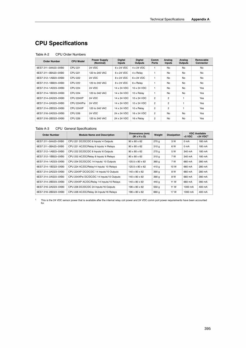
CPU Specifications
Table A-2 CPU Order Numbers
Order Number CPU Model Power Supply(Nominal)
DigitalInputs
DigitalOutputs
CommPorts
AnalogInputs
AnalogOutputs
RemovableConnector
6ES7 211--0AA23--0XB0 CPU 221 24 VDC 6 x 24 VDC 4 x 24 VDC 1 No No No
6ES7 211--0BA23--0XB0 CPU 221 120 to 240 VAC 6 x 24 VDC 4 x Relay 1 No No No
6ES7 212--1AB23--0XB0 CPU 222 24 VDC 8 x 24 VDC 6 x 24 VDC 1 No No No
6ES7 212--1BB23--0XB0 CPU 222 120 to 240 VAC 8 x 24 VDC 6 x Relay 1 No No No
6ES7 214--1AD23--0XB0 CPU 224 24 VDC 14 x 24 VDC 10 x 24 VDC 1 No No Yes
6ES7 214--1BD23--0XB0 CPU 224 120 to 240 VAC 14 x 24 VDC 10 x Relay 1 No No Yes
6ES7 214--2AD23--0XB0 CPU 224XP 24 VDC 14 x 24 VDC 10 x 24 VDC 2 2 1 Yes
6ES7 214--2AS23--0XB0 CPU 224XPsi 24 VDC 14 x 24 VDC 10 x 24 VDC 2 2 1 Yes
6ES7 214--2BD23--0XB0 CPU 224XP 120 to 240 VAC 14 x 24 VDC 10 x Relay 2 2 1 Yes
6ES7 216--2AD23--0XB0 CPU 226 24 VDC 24 x 24 VDC 16 x 24 VDC 2 No No Yes
6ES7 216--2BD23--0XB0 CPU 226 120 to 240 VAC 24 x 24 VDC 16 x Relay 2 No No Yes
Table A-3 CPU General Specifications
Order Number Module Name and Description Dimensions (mm)(W x H x D)
Weight Dissipation VDC Available+5 VDC +24 VDC1
6ES7 211--0AA23--0XB0 CPU 221 DC/DC/DC 6 Inputs/ 4 Outputs 90 x 80 x 62 270 g 3 W 0 mA 180 mA
6ES7 211--0BA23--0XB0 CPU 221 AC/DC/Relay 6 Inputs/ 4 Relays 90 x 80 x 62 310 g 6 W 0 mA 180 mA
6ES7 212--1AB23--0XB0 CPU 222 DC/DC/DC 8 Inputs/ 6 Outputs 90 x 80 x 62 270 g 5 W 340 mA 180 mA
6ES7 212--1BB23--0XB0 CPU 222 AC/DC/Relay 8 Inputs/ 6 Relays 90 x 80 x 62 310 g 7 W 340 mA 180 mA
6ES7 214--1AD23--0XB0 CPU 224 DC/DC/DC 14 Inputs/ 10 Outputs 120.5 x 80 x 62 360 g 7 W 660 mA 280 mA
6ES7 214--1BD23--0XB0 CPU 224 AC/DC/Relay14 Inputs/ 10 Relays 120.5 x 80 x 62 410 g 10 W 660 mA 280 mA
6ES7 214--2AD23--0XB0 CPU 224XP DC/DC/DC 14 Inputs/10 Outputs 140 x 80 x 62 390 g 8 W 660 mA 280 mA
6ES7 214--2AS23--0XB0 CPU 224XPsi DC/DC/DC 14 Inputs/10 Outputs 140 x 80 x 62 390 g 8 W 660 mA 280 mA
6ES7 214--2BD23--0XB0 CPU 224XP AC/DC/Relay 14 Inputs/10 Relays 140 x 80 x 62 440 g 11 W 660 mA 280 mA
6ES7 216--2AD23--0XB0 CPU 226 DC/DC/DC 24 Inputs/16 Outputs 196 x 80 x 62 550 g 11 W 1000 mA 400 mA
6ES7 216--2BD23--0XB0 CPU 226 AC/DC/Relay 24 Inputs/16 Relays 196 x 80 x 62 660 g 17 W 1000 mA 400 mA
1 This is the 24 VDC sensor power that is available after the internal relay coil power and 24 VDC comm port power requirements have been accountedfor.

S7-200 Programmable Controller System Manual
396
Table A-4 CPU Specifications
CPU 221 CPU 222 CPU 224 CPU 224XPCPU 224XPsi
CPU 226
Memory
User program sizewith run mode editwithout run mode edit
4096 bytes4096 bytes
8192 bytes12288 bytes
12288 bytes16384 bytes
16384 bytes24576 bytes
User data 2048 bytes 8192 bytes 10240 bytes 10240 bytes
Backup (super cap)
(optional battery)
50 hours typical (8 hours min. at 40°C)
200 days typical
100 hours typical (70hours min. at 40°C)200 days typical
100 hours typical (70 hours min. at 40°C)
200 days typical
I/O
Digital I/O 6 inputs/4outputs 8 inputs/6 outputs 14 inputs/10 outputs 14 inputs/10 outputs 24 inputs/16 outputs
Analog I/O none 2 inputs/1 output none
Digital I/O image size 256 (128 In/128 Out)
Analog I/O image size None 32 (16 In/16 Out) 64 (32 In/32 Out)
Max. expansion modules allowed None 2 modules1 7 modules1
Max. intelligentmodules allowed None 2 modules1 7 modules1
Pulse Catch inputs 6 8 14 24
High-Speed CountersSingle phase
Two phase
4 counters total4 at 30 kHz
2 at 20 kHz
6 counters total6 at 30 kHz
4 at 20 kHz
6 counters total4 at 30 kHz2 at 200 kHz3 at 20 kHz1 at 100 kHz
6 counters total6 at 30 kHz
4 at 20 kHz
Pulse outputs 2 at 20 kHz (DC outputs only) 2 at 100 kHz(DC outputs only)
2 at 20 kHz(DC outputs only)
General
Timers 256 total timers; 4 timers (1 ms); 16 timers (10 ms); 236 timers (100 ms)
Counters 256 (backed by super capacitor or battery)
Internal memory bitsStored on power down
256 (backed by super capacitor or battery)112 (stored to EEPROM)
Timed interrupts 2 with 1 ms resolution
Edge interrupts 4 up and/or 4 down
Analog adjustment 1 with 8 bit resolution 2 with 8 bit resolution
Boolean execution speed 0.22 µs per instruction
Real Time Clock Optional cartridge Built-in
Cartridge options Memory, Battery, and Real Time Clock Memory and battery
Communications Built-in
Ports (Limited Power) 1 RS--485 port 2 RS--485 ports
PPI, DP/T baud rates 9.6, 19.2, 187.5 kbaud
Freeport baud rates 1.2 kbaud to 115.2 kbaud
Max. cable length per segment With isolated repeater: 1000 m up to 187.5 kbaud, 1200 m up to 38.4 kbaudWithout isolated repeater: 50 m
Max. number of stations 32 per segment, 126 per network
Max. number of masters 32
Peer to Peer (PPI Master Mode) Yes (NETR/NETW)
MPI connections 4 total, 2 reserved (1 for a PG and 1 for an OP)
1 Youmust calculate your powerbudget to determine howmuch power (or current) the S7-200CPU canprovide for your configuration. If theCPU powerbudgetis exceeded, you may not be able to connect the maximum number of modules. See Appendix A for CPU and expansion module power requirements, andAppendix B to calculate your power budget.

Technical Specifications Appendix A
397
Table A-5 CPU Power Specifications
DC AC
Input Power
Input voltage 20.4 to 28.8 VDC 85 to 264 VAC (47 to 63 Hz)
Input currentCPU 221CPU 222CPU 224CPU 224XPCPU 224XPsiCPU 226
CPU only at 24 VDC80 mA85 mA110 mA120 mA120 mA150 mA
Max. load at 24 VDC450 mA500 mA700 mA900 mA900 mA1050 mA
CPU only30/15 mA at 120/240 VAC40/20 mA at 120/240 VAC60/30 mA at 120/240 VAC70/35 mA at 120/240 VAC--80/40 mA at 120/240 VAC
Max. load120/60 mA at120/240 VAC140/70 mA at 120/240 VAC200/100 mA at 120/240VAC220/100 mA at 120/240 VAC--320/160 mA at 120/240VAC
Inrush current 12 A at 28.8 VDC 20 A at 264 VAC
Isolation (field to logic) Not isolated 1500 VAC
Hold up time (loss of power) 10 ms at 24 VDC 20/80 ms at 120/240 VAC
Fuse (non-replaceable) 3 A, 250 V Slow Blow 2 A, 250 V Slow Blow
24 VDC Sensor Power
Sensor voltage (Limited Power) L+ minus 5 V 20.4 to 28.8 VDC
Current limit 1.5 A peak, thermal limit non-destructive (See Table A-3 for rated load.)
Ripple noise Derived from input power Less than 1 V peak-to-peak
Isolation (sensor to logic) Not isolated
Table A-6 CPU Digital Input Specifications
General 24 VDC Input (CPU 221, CPU 222,CPU 224, CPU 226)
24 VDC Input (CPU 224XP, CPU 224XPsi)
Type Sink/Source (IEC Type 1 Sink) Sink/Source (IEC Type 1 Sink, except I0.3 to I0.5)
Rated voltage 24 VDC at 4 mA typical 24 VDC at 4 mA typical
Max. continuous permissible voltage 30 VDC
Surge voltage 35 VDC for 0.5 s
Logic 1 (min.) 15 VDC at 2.5 mA 15 VDC at 2.5 mA (I0.0 to I0.2 and I0.6 to I1.5)4 VDC at 8 mA (I0.3 to I0.5)
Logic 0 (max.) 5 VDC at 1 mA 5 VDC at 1 mA (I0.0 to I0.2 and I0.6 to I1.5)1 VDC at 1 mA (I0.3 to I0.5)
Input delay Selectable (0.2 to 12.8 ms)
Connection of 2 wire proximity sensor (Bero)Permissible leakage current (max.) 1 mA
Isolation (field to logic)Optical (galvanic)Isolation groups
Yes500 VAC for 1 minuteSee wiring diagram
High Speed Counter (HSC) input rateHSC InputsAll HSCAll HSCHC4, HC5 on CPU 224XPand CPU 224XPsi only
Logic 1 Level Single phase Two phase15 to 30 VDC 20 kHz 10 kHz15 to 26 VDC 30 kHz 20 kHz> 4 VDC 200 kHz 100 kHz
Inputs on simultaneously All AllCPU 224XP AC/DC/RELAY only:
All at 55° C with DC inputs at 26 VDC max.All at 50° C with DC inputs at 30 VDC max.
Cable length (max.)ShieldedUnshielded
500 m normal inputs, 50 m HSC inputs1
300 m normal inputs
1 Shielded twisted pair is recommended for HSC inputs.

S7-200 Programmable Controller System Manual
398
Table A-7 CPU Digital Output Specifications
General 24 VDC Output(CPU 221, CPU 222,CPU 224, CPU 226)
24 VDC Output(CPU 224XP)
24 VDC Output(CPU 224XPsi)
Relay Output
Type Solid State-MOSFET (Sourcing) Solid State-MOSFET(Sinking)
Dry contact
Rated voltage 24 VDC 24 VDC 24 VDC 24 VDC or 250 VAC
Voltage range 20.4 to 28.8 VDC 5 to 28.8 VDC (Q0.0 toQ0.4)20.4 to 28.8 VDC (Q0.5 toQ1.1)
5 to 28.8 VDC 5 to 30 VDC or 5 to 250VAC
Surge current (max.) 8 A for 100 ms 5 A for 4 s @ 10% dutycycle
Logic 1 (min.) 20 VDC at maximumcurrent
L+ minus 0.4 V at max.current
External Voltage Railminus 0.4V with 10Kpullup to External VoltageRail
--
Logic 0 (max.) 0.1 VDC with 10 K Ω Load 1M + 0.4V at max. load --
Rated current per point (max.) 0.75 A 2.0 A
Rated current per common (max.) 6 A 3.75 A 7.5 A 10 A
Leakage current (max.) 10 µ A --
Lamp load (max.) 5 W 30 W DC; 200 W AC2, 3
Inductive clamp voltage L+ minus 48 VDC, 1 W dissipation 1M +48 VDC, 1 Wdissipation
--
On State resistance (contact) 0.3 Ω typical (0.6 Ω max.) 0.2 Ω (max. when new)
IsolationOptical (galvanic, field to logic)Logic to contactResistance (logic to contact)Isolation groups
500 VAC for 1 minute----See wiring diagram
--1500 VAC for 1 minute100 M ΩSee wiring diagram
Delay (max.)Off to on (µs)
On to off (µs)
Switching
2µs (Q0.0, Q0.1),15µs (all other)10µs (Q0.0, Q0.1), 130µs(all other)--
0.5µs (Q0.0, Q0.1), 15µs (all other)
1.5µs (Q0.0, Q0.1), 130µs (all other)
--
--
--
10 ms
Pulse frequency (max.) 20 kHz1 (Q0.0 and Q0.1) 100 kHz1 (Q0.0 and Q0.1) 100 kHz1 (Q0.0 and Q0.1) 1 Hz
Lifetime mechanical cycles -- -- -- 10,000,000 (no load)
Lifetime contacts -- -- -- 100,000 (rated load)
Outputs on simultaneously All at 55° C (horizontal), All at 45° C (vertical)
Connecting two outputs in parallel Yes, only outputs in same group No
Cable length (max.)ShieldedUnshielded
500 m150 m
1 Depending on your pulse receiver and cable, an additional external load resistor (at least 10% of rated current) may improve pulse signal quality and noiseimmunity.
2 Relay lifetime with a lamp load will be reduced by 75% unless steps are taken to reduce the turn-on surge below the surge current rating of the output.3 Lamp load wattage rating is for rated voltage. Reduce the wattage rating proportionally for voltage being switched (for example 120 VAC -- 100 W).
WarningWhen a mechanical contact turns on output power to the S7-200 CPU, or any digital expansion module, itsends a “1” signal to the digital outputs for approximately 50 microseconds.
This could cause unexpected machine or process operation which could result in death or serious injury topersonnel, and/or damage to equipment.
You must plan for this, especially if you are using devices which respond to short duration pulses.

Technical Specifications Appendix A
399
Table A-8 CPU 224XP and CPU 224XPsi Analog Input Specifications
General Analog Input (CPU 224XP, CPU 224XPsi)
Number of inputs 2 points
Analog input type Single-ended
Voltage range ±10 V
Data word format, full scale range --32,000 to +32,000
DC Input impedance >100 KΩ
Maximum input voltage 30 VDC
Resolution 11 bits plus 1 sign bit
LSB value 4.88 mV
Isolation None
AccuracyWorst case 0° to 55° CTypical 25° C
±2.5% of full scale±1.0% of full scale
Repeatability ±0.05% of full scale
Analog to digital conversion time 125 msec
Conversion type Sigma Delta
Step response 250 ms max.
Noise rejection --20 dB @ 50 Hz typical
Table A-9 CPU 224XP and CPU 224XPsi Analog Output Specifications
General Analog Output (CPU 224XP, CPU 224XPsi)
Number of outputs 1 point
Signal rangeVoltageCurrent
0 to 10 V (Limited Power)0 to 20 mA (Limited Power)
Data word format, full range 0 to +32767
Date word format, full scale 0 to +32000
Resolution, full range 12 bits
LSB valueVoltageCurrent
2.44 mV4.88 µA
Isolation none
AccuracyWorst case, 0° to 55° C
Voltage outputCurrent output
Typical 25° CVoltage outputCurrent output
± 2% of full-scale± 3% of full-scale
± 1% of full-scale± 1% of full-scale
Settling timeVoltage outputCurrent output
< 50 µS< 100 µS
Maximum output driveVoltage outputCurrent output
≥ 5000 Ω minimum≤ 500 Ω maximum

S7-200 Programmable Controller System Manual
400
Wiring Diagrams
+
24 VDC Input
Used as Sinking Inputs
1M .0 .1 .2 .31M .0 .1 .2 .3
24 VDC Input
Used as Sourcing Inputs
+
Relay Output
1L .0 .1 .2
L(+)
N(--)
24 VDC Output(Sinking)
1M .0 .1 .2
+
VLO
AD
CPU 224 XP and CPU 224XPsiAnalog Input/Output
M I V M A+ B+
ILOAD
--+
+--
+--
InputsOutput
24 VDC Output(Sourcing)
1M 1L+ .0 .1 .2
+
Figure A-2 CPU Inputs and Outputs
L+
24 VDCSensorPowerOutput
24 VDCSensorPowerOutput
120/240 VAC Power
CPU 221 DC/DC/DC(6ES7 211--0AA23--0XB0)
24 VDC Power
CPU 221 AC/DC/Relay(6ES7 211--0BA23--0XB0)
M L+ 0.0 0.1 0.2 0.3 DC
0.0 0.1 0.2 0.3 2M 0.4 0.5 M L+1M
+
+
+
M
+
1L 0.0 0.1 0.2 2L 0.3 N L1
0.1 0.2 0.3 2M 0.4 0.5 M L+
+
L(+)
N(--)
0.01M
L(+)
N(--)
AC
+
Figure A-3 CPU 221 Wiring Diagrams

Technical Specifications Appendix A
401
CPU 224 DC/DC/DC(6ES7 214--1AD23--0XB0)
CPU 224 AC/DC/Relay(6ES7 214--1BD23--0XB0)
24 VDC Power
24 VDC SensorPower Output
24 VDC SensorPower Output
CPU 222 DC/DC/DC(6ES7 212--1AB23--0XB0) 24 VDC Power
24 VDCSensorPowerOutput
120/240 VAC Power
24 VDCSensorPowerOutput
CPU 222 AC/DC/Relay(6ES7 212--1BB23--0XB0)
120/240 VAC Power
M L+ 0.0 0.1 0.2 0.3 L+ DC
0.0 0.1 0.2 0.3 2M 0.4 0.5 M L+1M
+
+
+
M
+
0.4 0.5
0.6 0.7
1L 0.0 0.1 0.2 2L 0.3 0.4 N L1
0.1 0.2 0.3 2M 0.4 0.5 0.6 0.7 M L+
+
L(+)
N(--)
0.01M
L(+)
N(--)
AC0.5
1M 1L+ 0.0 0.1 0.2 0.3 L+ DC
0.0 0.1 0.2 0.3 0.4 0.5 L+1M
+
+
+
M
+
0.4 2M
+
0.6 0.7 1.0 1.1 1.2 1.3 1.4 1.5 M2M
2L+ 0.5 0.6 0.7 1.0 1.1
1L 0.0 0.1 0.2 0.3 L1 AC
0.0 0.1 0.2 0.3 0.4 0.5 L+1M
+ +
N0.42L
0.6 0.7 1.0 1.1 1.2 1.3 1.4 1.5 M2M
3L0.5 0.6 0.7 1.0 1.1
L(+)
N(--)
L(+)
N(--)
L(+)
N(--)
+
Figure A-4 CPU 222 and CPU 224 Wiring Diagrams
S7-200 Programmable Controller System Manual
402
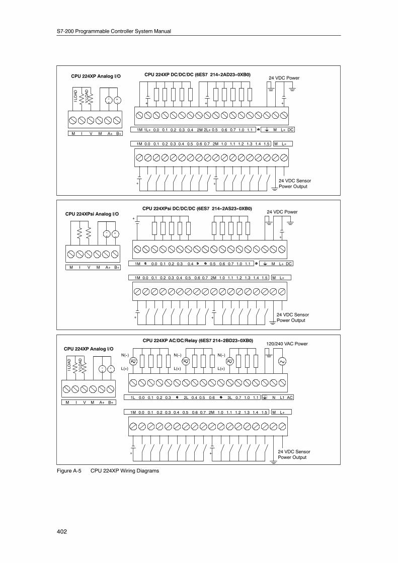
CPU 224XP DC/DC/DC (6ES7 214--2AD23--0XB0)
CPU 224XP AC/DC/Relay (6ES7 214--2BD23--0XB0)
24 VDC Power
24 VDC SensorPower Output
24 VDC SensorPower Output
120/240 VAC Power
1M 1L+ 0.0 0.1 0.2 0.3 L+ DC
0.0 0.1 0.2 0.3 0.4 0.5 L+1M
+
+
+
M
+
0.4 2M
+
0.6 0.7 1.0 1.1 1.2 1.3 1.4 1.5 M2M
2L+ 0.5 0.6 0.7 1.0 1.1
1L 0.0 0.1 0.2 0.3 L1 AC
0.0 0.1 0.2 0.3 0.4 0.5 L+1M
+ +
N0.42L
0.6 0.7 1.0 1.1 1.2 1.3 1.4 1.5 M2M
3L0.5 0.6 0.7 1.0 1.1
L(+)
N(--)
L(+)
N(--)
L(+)
N(--)
VLO
AD
CPU 224XP Analog I/O
M I V M A+ B+
ILOAD
VLO
AD
CPU 224XP Analog I/O
M I V M A+ B+
ILOAD
--+
+--
--+
+--
CPU 224XPsi DC/DC/DC (6ES7 214--2AS23--0XB0)24 VDC Power
24 VDC SensorPower Output
1M 0.0 0.1 0.2 0.3 L+ DC
0.0 0.1 0.2 0.3 0.4 0.5 L+1M
+ +
M
+
0.4
0.6 0.7 1.0 1.1 1.2 1.3 1.4 1.5 M2M
0.5 0.6 0.7 1.0 1.1
CPU 224XPsi Analog I/O
M I V M A+ B+
--+
+--
+
Figure A-5 CPU 224XP Wiring Diagrams

Technical Specifications Appendix A
403
1.1
+ +
1L 0.0 0.1 0.2 0.3 0.7 1.02L 0.4 0.5 0.6 3L 1.1 1.2 1.3 1.4 1.5 1.6 1.7 N ACL1
0.0 0.1 0.2 0.3 0.4 0.5 0.6 0.71M 1.0 1.1 1.2 1.3 1.4 1.5 1.6 1.7 2.0 2.1 2.2 2.3 2.42M 2.5 2.6 2.7 M L+
CPU 226 DC/DC/DC (6ES7 216--2AD23--0XB0)
CPU 226 AC/DC/Relay (6ES7 216--2BD23--0XB0)
24 VDC Power
+ +
++ +
1M 1L+ 0.0 0.1 0.2 0.3 2M 2L+0.4 0.5 0.6 0.7 1.0 1.1 1.2 1.3 1.4 1.5 1.6 1.7 M DCL+
0.0 0.1 0.2 0.3 0.4 0.5 0.6 0.71M 1.0 1.2 1.3 1.4 1.5 1.6 1.7 2.0 2.1 2.2 2.3 2.42M 2.5 2.6 2.7 M L+
N(--)
L(+)
N(--) N(--)
L(+) L(+)
24 VDC Power
24 VDCPowerOutput
24 VDCSensorPowerOutput
+ +
1L+ 0.0 0.1 0.2 0.3 2M 2L+0.4 0.5 0.6 0.7 1.0 1.1 1.2 1.3 1.4 1.5 1.6 1.7 M DCL+
0.0 0.1 0.2 0.3 0.4 0.5 0.6 0.71M 1.0 1.5 1.6 1.7 2.0 2.1 2.2 2.3 2.42M 2.5 2.6 2.7 M L+
N(--)
L(+)
N(--)
L(+)
120/240 VACPower
Figure A-6 CPU 226 Wiring Diagrams
Table A-10 Pin Assignments for the S7-200 Communications Port (Limited Power)
Connector Pin Number PROFIBUS Signal Port 0/Port 1
1 Shield Chassis ground
2 24 V Return Logic common
Pin 6Pin 1 3 RS-485 Signal B RS-485 Signal B
Pin 64 Request-to-Send RTS (TTL)
5 5 V Return Logic common
Pin 96 +5 V +5 V, 100 Ω series resistor
Pin 9
Pin 5 7 +24 V +24 V
8 RS-485 Signal A RS-485 Signal A
9 Not applicable 10-bit protocol select (input)
Connector shell Shield Chassis ground

S7-200 Programmable Controller System Manual
404
Digital Expansion Modules Specifications
Table A-11 Digital Expansion Modules Order Numbers
Order Number Expansion Model Digital Inputs Digital Outputs RemovableConnector
6ES7 221--1BF22--0XA0 EM 221 Digital Input 8 x 24 VDC 8 x 24 VDC -- Yes
6ES7 221--1EF22--0XA0 EM 221 Digital Input 8 x 120/230 VAC 8 x 120/230 VAC -- Yes
6ES7 221--1BH22--0XA0 EM 221 Digital Input 16 x 24 VDC 16 x 24 VDC -- Yes
6ES7 222--1BD22--0XA0 EM 222 Digital Output 4 x 24 VDC--5A -- 4 x 24 VDC--5A Yes
6ES7 222--1HD22--0XA0 EM 222 Digital Output 4 x Relays--10A -- 4 x Relay--10A Yes
6ES7 222--1BF22--0XA0 EM 222 Digital Output 8 x 24 VDC -- 8 x 24 VDC--0.75A Yes
6ES7 222--1HF22--0XA0 EM 222 Digital Output 8 x Relays -- 8 x Relay--2A Yes
6ES7 222--1EF22--0XA0 EM 222 Digital Output 8 x 120/230 VAC -- 8 x 120/230 VAC Yes
6ES7 223--1BF22--0XA0 EM 223 24 VDC Digital Comb 4 Inputs/4 Outputs 4 x 24 VDC 4 x 24 VDC--0.75A Yes
6ES7 223--1HF22--0XA0 EM 223 24 VDC Digital Comb 4 Inputs/4 Relay Outputs 4 x 24 VDC 4 x Relay--2A Yes
6ES7 223--1BH22--0XA0 EM 223 24 VDC Digital Comb 8 Inputs/8 Outputs 8 x 24 VDC 8 x 24 VDC--0.75A Yes
6ES7 223--1PH22--0XA0 EM 223 24 VDC Digital Comb 8 Inputs/8 Relay Outputs 8 x 24 VDC 8 x Relay--2A Yes
6ES7 223--1BL22--0XA0 EM 223 24 VDC Digital Comb 16 Inputs/16 Outputs 16 x 24 VDC 16 x 24 VDC--0.75A Yes
6ES7 223--1PL22--0XA0 EM 223 24 VDC Digital Comb 16 Inputs/16 Relay Outputs 16 x 24 VDC 16 x Relay--2A Yes
6ES7 223--1BM22--0XA0 EM 223 24 VDC Digital Comb 32 Inputs/32 Outputs 32 x 24 VDC 32 x 24 VDC--0.75 A Yes
6ES7 223--1PM22--0XA0 EM 223 24 VDC Digital Comb 32 Inputs/32 Relay Outputs 32 x 24 VDC 32 x Relay--2 A Yes
Table A-12 Digital Expansion Modules General Specifications
Order Number Module Name and Description Dimensions (mm)(W x H x D)
Weight Dissipation VDC Requirements+5 VDC +24 VDC
6ES7 221--1BF22--0XA0 EM 221 DI 8 x 24 VDC 46 x 80 x 62 150 g 2 W 30 mA ON: 4 mA/input
6ES7 221--1EF22--0XA0 EM 221 DI 8 x 120/230 VAC 71.2 x 80 x 62 160 g 3 W 30 mA --
6ES7 221--1BH22--0XA0 EM 221 DI 16 x 24 VDC 71.2 x 80 x 62 160 g 3 W 70 mA ON: 4 mA/input
6ES7 222--1BD22--0XA0 EM 222 DO 4 x 24 VDC--5A 46 x 80 x 62 120 g 3 W 40 mA --
6ES7 222--1HD22--0XA0 EM 222 DO 4 x Relays--10A 46 x 80 x 62 150 g 4 W 30 mA ON: 20 mA/output
6ES7 222--1BF22--0XA0 EM 222 DO 8 x 24 VDC 46 x 80 x 62 150 g 2 W 50 mA --
6ES7 222--1HF22--0XA0 EM 222 DO 8 x Relays 46 x 80 x 62 170 g 2 W 40 mA ON: 9 mA/output
6ES7 222--1EF22--0XA0 EM 222 DO 8 x 120/230 VAC 71.2 x 80 x 62 165 g 4 W 110 mA --
6ES7 223--1BF22--0XA0 EM 223 24 VDC 4 In/4 Out 46 x 80 x 62 160 g 2 W 40 mA ON: 4 mA/input
6ES7 223--1HF22--0XA0 EM 223 24 VDC 4 In/4 Relays 46 x 80 x 62 170 g 2 W 40 mA ON: 9 mA/output,4 mA/input
6ES7 223--1BH22--0AX0 EM 223 24 VDC 8 In/8 Out 71.2 x 80 x 62 200 g 3 W 80 mA ON: 4 mA/input
6ES7 223--1PH22--0XA0 EM 223 24 VDC 8 In/8 Relays 71.2 x 80 x 62 300 g 3 W 80 mA ON: 9 mA/output,4 mA/input
6ES7 223--1BL22--0XA0 EM 223 24 VDC 16 In/16 Out 137.3 x 80 x 62 360 g 6 W 160 mA ON: 4 mA/input
6ES7 223--1PL22--0XA0 EM 223 24 VDC 16 In/16 Relays 137.3 x 80 x 62 400 g 6 W 150 mA ON: 9 mA/output,4 mA/input
6ES7 223--1BM22--0XA0 EM 223 24 VDC 32 In/32 Out 196 x 80 x 62 500 g 9 W 240 mA ON: 4 mA/input
6ES7 223--1PM22--0XA0 EM 223 24 VDC 32 In/32 Relay 196 x 80 x 62 580 g 13 W 205 mA ON: 9 mA/output4 mA/input

Technical Specifications Appendix A
405
Table A-13 Digital Expansion Modules Input Specifications
General 24 VDC Input 120/230 VAC Input (47 to 63 HZ)
Type Sink/Source (IEC Type 1 sink) IEC Type I
Rated voltage 24 VDC at 4 mA 120 VAC at 6 mA or 230 VAC at 9 mA nominal
Maximum continuous permissible voltage 30 VDC 264 VAC
Surge voltage (max.) 35 VDC for 0.5 s --
Logic 1 (min.) 15 VDC at 2.5 mA 79 VAC at 2.5 mA
Logic 0 (max.) 5 VDC at 1 mA 20 VAC or 1 mA AC
Input delay (max.) 4.5 ms 15 ms
Connection of 2 wire proximity sensor(Bero)
Permissible leakagecurrent (max.)
1 mA 1 mA AC
IsolationOptical (galvanic, field to logic)Isolation groups
500 VAC for 1 minuteSee wiring diagram
1500 VAC for 1 minute1 point
Inputs on simultaneously All at 55° C (horizontal), All on at 45° C (vertical)
Cable length (max.)ShieldedUnshielded
500 m300 m
500 m300 m
0N .00N
N
L1
120/230 AC Input24 VDC Input
Used as Sinking Inputs
1M .0 .1 .2 .3
+
1M .0 .1 .2 .3
24 VDC Input
Used as Sourcing Inputs
+
Figure A-7 S7-200 Digital Expansion Modules Inputs

S7-200 Programmable Controller System Manual
406
Table A-14 Digital Expansion Modules Output Specifications
General24 VDC Output Relay Output
120/230 VAC OutputGeneral0.75 A 5 A 2 A 10 A
120/230 VAC Output
Type Solid state-MOSFET (Sourcing) Dry contact Triac, zero-cross turn-on
Rated voltage 24 VDC 24 VDC or 250 VAC 120/230 VAC
Voltage range 20.4 to 28.8 VDC 5 to 30 VDC or5 to 250 VAC
12 to 30 VDC or12 to 250 VAC
40 to 264 VAC(47 to 63 Hz)
24 VDC coil power voltage range -- 20.4 to 28.8 VDC --
Surge current (max.) 8 A for 100 ms 30 A 5 A for 4 s @ 10%duty cycle
15 A for 4 s @10% duty cycle
5 A rms for 2 AC cycles
Logic 1 (min.) 20 VDC -- L1 (--0.9 V rms)
Logic 0 (max.) 0.1 VDC with10 K Ω Load
0.2 VDC with 5 KΩ Load
-- --
Rated current per point (max.) 0.75 A 5 A 2.00 A 10 A resistive;2 A DC inductive;3 A AC inductive
0.5 A AC1
Rated current per common (max.) 10 A 5 A 10 A 10 A 0.5 A AC
Leakage current (max.) 10 µA 30 µA -- 1.1 mA rms at 132 VACand 1.8 mA rrms at 264VAC
Lamp load (max.) 5 W 50 W 30 W DC/200 W AC4,5
100 W DC/1000 W AC
60 W
Inductive clamp voltage L+ minus 48 V L+ minus 47 V2 -- --
On state resistance (contact) 0.3 Ω typical(0.6 Ω max.)
0.05 Ω max. 0.2 Ω max. when new 0.1 Ω max.when new
410 Ω max. when loadcurrent is less than0.05A
IsolationOptical (galvanic, field to logic)Coil to logicCoil to contactResistance (coil to contact)Isolation groups
500 VAC for 1 minute------See wiring diagram
--None1500 VAC for 1 minute100 M Ω min. when newSee wiring diagram
1500 VAC for 1minute------1 point
Delay Off to On/On to Off (max.)Switching (max.)
50 µs / 200 µs--
500 µs--
--10 ms
--15 ms
0.2 ms + 1/2 AC cycle--
Switching frequency (max.) -- 1 Hz 10 Hz
Lifetime mechanical cycles -- 10,000,000 (no load) 30,000,000(no load)
--
Lifetime contacts -- 100,000 (rated load) 30,000(rated load)
--
Output on simultaneously All at 55° C (horizontal), All at 45° C (vertical) All at 55 °C(horizontal) with20A max. modulecurrent. All at45°C (vertical) with20A max. modulecurrent5. All at 40°C (horizontal) with10A per point
All at 55° C (horizontal),All at 45° C (vertical)
Connecting two outputs in parallel Yes, only outputs in same group No No
Cable length (max.)ShieldedUnshielded
500 m150 m
500 m150 m
500 m150 m
1 Load current must be full wave AC and must not be half-wave because of the zero-cross circuitry. Minimum load current is 0.05 A AC. With a load currentbetween 5 mA and 50 mA AC, the current can be controlled, but there is an additional voltage drop due to series resistance of 410 Ohms.
2 If the output overheats due to excessive inductive switching or abnormal conditions, the output point may turn off or be damaged. The output could overheator be damaged if the output is subjected to more than 0.7 J of energy switching an inductive load off. To eliminate the need for this limitation, a suppressioncircuit as described in Chapter 3 can be added in parallel with the load. These components need to be sized properly for the given application.
3 The EM 222 DO 4 x Relay has a different FM rating than the rest of the S7-200. This module has a T4 rating, instead of T4A for FM Class I, Division GroupsA, B, C, and D Hazardous Locations.
4 Relay lifetime with a lamp load will be reduced by 75% unless steps are taken to reduce the turn-on surge below the surge current rating of the output.5 Lamp load wattage rating is for rated voltage. Reduce the wattage rating proportionally for voltage being switched (for example 120 VAC -- 100 W).
WarningWhen a mechanical contact turns on output power to the S7-200 CPU, or any digital expansion module, itsends a “1” signal to the digital outputs for approximately 50 microseconds.
This could cause unexpected machine or process operation which could result in death or serious injury topersonnel, and/or damage to equipment.
You must plan for this, especially if you are using devices which respond to short duration pulses.

Technical Specifications Appendix A
407
24 VDC Output
1M 1L+ .0 .1 .2
+
0L .00L
L1
N
120/230 AC OutputRelay Output
1L .0 .1 .2
L(+)
N(--)
Figure A-8 S7-200 Digital Expansion Modules Outputs
Wiring Diagrams
EM 223 24 VDCDigital Combination4 Inputs/ 4 Outputs(6ES7 223--1BF22--0AX0)
EM 223 24 VDCDigital Combination4 Inputs/4 Relay Outputs(6ES7 223--1HF22--0XA0)
24 VDCCoilPower
1M 1L+ .0 .1 .2 .3
1M .0 .1 .2 .3
+
+
.0 .1 .2 .3
1M .0 .1 .2 .3
+
L(+)
N(--)
L+M
1L
+
24 VDCCoilPower
.0 1L .1
2L 3L .3
L(+)
N(--)
L+M
0L
+
L(+)
N(--)
N(--)
L(+)
N(--)
L(+)
.2
EM 222Digital Output4 x Relays--10A(6ES7 222 1HD22--0XA0)
Figure A-9 Wiring Diagrams for EM 222 and EM 223 Expansion Modules

S7-200 Programmable Controller System Manual
408
EM 222 Digital Output 8 x 24 VDC(6ES7 222--1BF22--0XA0)
EM 221 Digital Input 8 x 24 VDC(6ES7 221--1BF22--0XA0)
24 VDC Coilpower
.0 .1 .2 .3
2M .4 .5 .6 .7
+
1M
+
1M 1L+ .0 .1 .2 .3
2L+ .4 .5 .6 .7
+
+
2M
.0 .1 .2 .3
2L .4 .5 .6 .7
L(+)
N(--)
L+M
1L
+
N(--)
L(+)
EM 222 Digital Output 8 x Relays(6ES7 222 1HF22--0XA0)
1M .0 .1 .2 .3 2M .4 .5 .6 .7
3M .0 .1 .2 .3 4M .4 .5 .6 .7
+
EM 221 Digital Input 16 x 24 VDC (6ES7 221--1BH22--0XA0)
+
++
EM 221 Digital Input 8 x AC 120//230 V(6ES7 221--1EF22--0XA0)
0N 0N .0 1N 1N .1 2N 2N .2 3N 3N .3
.4 5N 5N .5 6N 6N .6 7N 7N .74N
EM 222 Digital Output 8 x AC 120/230 V(6ES7 222--1EF22--0AX0)
0L 0L .0 1L 1L 2L.1 .2 3L 3L .3
.4 5L 5L .5 6L 6L .6 7L 7L .74L
2L
L1
N
EM 222 Digital Output 4 x 24 VDC--5A(6ES7 222--1BD22--0XA0)
0M 0L+ 1M 1L+ .1
2L+ .2 3M 3L+ .3
+
+
2M
.0
+
+
Figure A-10 Wiring Diagrams for EM 221 and EM 222 Expansion Modules
Technical Specifications Appendix A
409
1M 1L+ .0 .1 .2 .3 2M 2L+ .4 .5 .6 .7
1M .0 .1 .2 .3 2M .4 .5 .6 .7
++
+
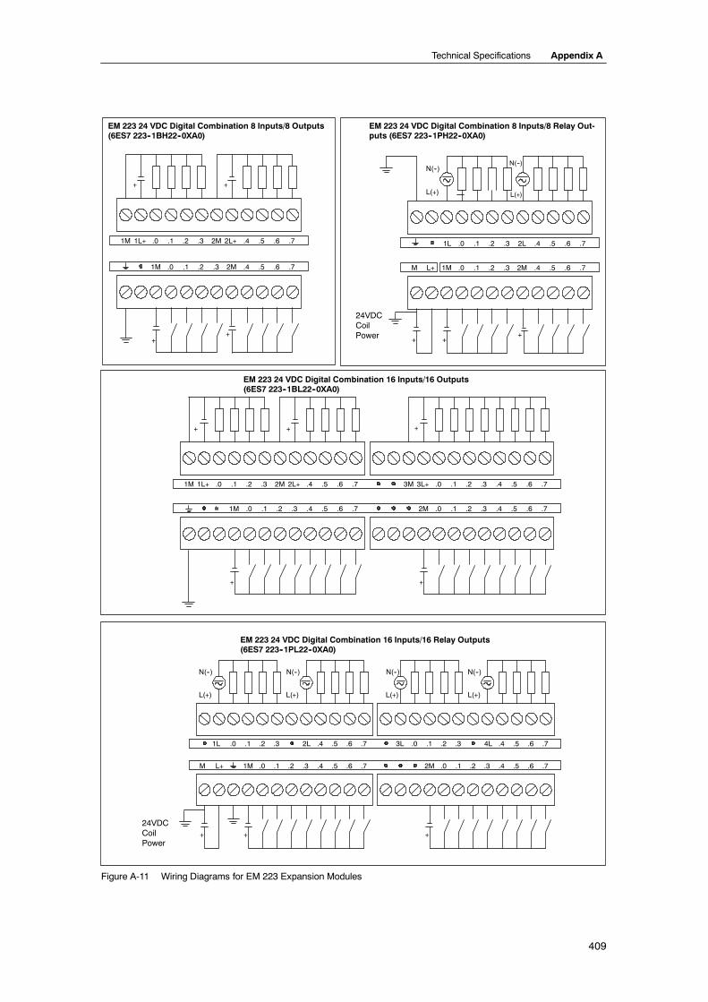
EM 223 24 VDC Digital Combination 16 Inputs/16 Outputs(6ES7 223--1BL22--0XA0)
EM 223 24 VDC Digital Combination 16 Inputs/16 Relay Outputs(6ES7 223--1PL22--0XA0)
EM 223 24 VDC Digital Combination 8 Inputs/8 Outputs(6ES7 223--1BH22--0XA0)
EM 223 24 VDC Digital Combination 8 Inputs/8 Relay Out-puts (6ES7 223--1PH22--0XA0)
24VDCCoilPower
.0 .1 .2 .3 2L .4 .5 .6 .7
1M .0 .1 .2 .3 2M .4 .5 .6 .7
++
L(+)
N(--)
L+M
1L
+
3M 3L+ .0 .1 .2 .3 .4 .5 .6 .7
.0 .1 .2 .32M .4 .5 .6 .7
++++
+
1M 1L+ .0 .1 .2 .3 .4 .5 .6 .72M 2L+
.0 .1 .2 .31M .4 .5 .6 .7
L(+)
N(--)
3L .0 .1 .2 .3 .4 .5 .6 .7
2M .0 .1 .2 .3 .4 .5 .6 .7
L(+)
N(--)
L(+)
N(--)
++ +
1M .0 .1 .2 .3 .4 .5 .6 .7M L+
4L1L .0 .1 .2 .3 .4 .5 .6 .72L
N(--)
L(+)
+
24VDCCoilPower
N(--)
L(+)
Figure A-11 Wiring Diagrams for EM 223 Expansion Modules

S7-200 Programmable Controller System Manual
410
+ +
2M 2L+ 2.0 2.1 2.2 2.3 2.4 2.5 2.6 2.7 3.0 3.1 3.2 3.3 3.4 3.5 3.6 3.7
+
1M 1L+ 0.0 0.1 0.2 0.3 0.6 0.7 1.0 1.10.4 0.5 1.2 1.3 1.4 1.5 1.6 1.7
+
1.5 1.6 1.7 2M1.0 2.0 2.1 2.2 2.30.0 0.1 0.2 0.31M 0.4 0.5 0.6 0.7 2.4 2.5 2.6 2.7 3.0 3.1 3.21.41.1 1.2 1.3 3.3 3.4 3.5 3.6 3.7
+
1.7 2.0 2.1 2.2 2.3 2.4 2.5 3L 2.6 2.7 3.0 3.1 3.2 3.3 3.4 3.5 3.6 3.7
1.5 1.6 1.7 2M1.0 2.0 2.1 2.2 2.3
1L 0.0 0.1 0.2 0.3 0.6 0.7 1.0 1.10.4 0.5 1.2 2L 1.3 1.4 1.5 1.6
0.0 0.1 0.2 0.31M 0.4 0.5 0.6 0.7 2.4 2.5 2.6 2.7 3.0 3.1 3.21.41.1 1.2 1.3 3.3 3.4 3.5 3.6 3.7
++
L+M
L(+)
N(-) N(-)
L(+)
N(-)
L(+)
EM 223 24 VDC Digital Combination 32 Inputs/32 Outputs(6ES7 223--1BM22--0XA0)
EM 223 24 VDC Digital Combination 32 Inputs/32 Relay Outputs(6ES7 223--1PM22--0XA0)
Figure A-12 Wiring Diagrams for EM 223 Expansion Modules

Technical Specifications Appendix A
411
Analog Expansion Modules Specifications
Table A-15 Analog Expansion Modules Order Numbers
Order Number Expansion Model EM Inputs EM Outputs RemovableConnector
6ES7 231--0HC22--0XA0 EM 231 Analog Input, 4 Inputs 4 -- No
6ES7 231--0HF22--0XA0 EM 231 Analog Input, 8 Inputs 8 -- No
6ES7 232--0HB22--0XA0 EM 232 Analog Output, 2 Outputs -- 2 No
6ES7 232--0HD22--0XA0 EM 232 Analog Output, 4 Outputs -- 4 No
6ES7 235--0KD22--0XA0 EM 235 Analog Combination 4 Inputs/1 Output 4 11 No
1 The CPU reserves 2 analog output points for this module.
Table A-16 Analog Expansion Modules General Specifications
Order Number Module Name andDescription
Dimensions (mm)(W x H x D)
Weight Dissipation VDC Requirements+5 VDC +24 VDC
6ES7 231--0HC22--0XA0 EM 231 Analog Input, 4 Inputs 71.2 x 80 x 62 183 g 2 W 20 mA 60 mA
6ES7 231--0HF22--0XA0 EM 231 Analog Input, 8 Inputs 71.2 x 80 x 62 190 g 2 W 20 mA 60 mA
6ES7 232--0HB22--0XA0 EM 232 Analog Output,2 Outputs
46 x 80 x 62 148 g 2 W 20 mA 70 mA (with bothoutputs at 20 mA)
6327 232--0HD22--0XA0 EM 232 Analog Output, 4Outputs
71.2 x 80 x 62 190 g 2 W 20 mA 100 MA (with alloutputs at 20 mA)
6ES7 235--0KD22--0XA0 EM 235 Analog Combination4 Inputs/1 Output
71.2 x 80 x 62 186 g 2 W 30 mA 60 mA (with outputat 20 mA)
Table A-17 Analog Expansion Modules Input Specifications
General 6ES7 231--0HC22--0XA06ES7 235--0KD22--0XA0
6ES7 231--0HF22--0XA0
Data word formatBipolar, full-scale rangeUnipolar, full-scale range
(See Figure A-16)--32000 to +320000 to 32000
DC Input impedance ≥2 MΩ voltage input250 Ω current input
> 2 MΩ voltage input250 Ω current input
Input filter attenuation --3 db at 3.1 Khz
Maximum input voltage 30 VDC
Maximum input current 32 mA
ResolutionBipolarUnipolar
11 bits plus 1 sign bit12 bits
Isolation (field to logic) None
Input type Differential Differential voltage, two channels selectable forcurrent
Input rangesVoltage:
Selectable, see Table A-20 for availableranges
Current:0 to 20 mA
Voltage:Channels 0 to 70 to +10V, 0 to +5V and +/--2.5
Current:Channels 6 and 70 to 20mA
Input resolution See Table A-20 See Table A-22
Analog to digital conversion time < 250 µs < 250 µs
Analog input step response 1.5 ms to 95% 1.5 ms to 95%
Common mode rejection 40 dB, DC to 60 Hz 40 dB, DC to 60 Hz
Common mode voltage Signal voltage plus common mode voltagemust be ≤ ±12 V
Signal voltage plus common mode voltagemust be ≤ ±12 V
24 VDC supply voltage range 20.4 to 28.8 VDC (Class 2, Limited Power, or sensor power from PLC)

S7-200 Programmable Controller System Manual
412
Table A-18 Analog Expansion Modules Output Specifications
General 6ES7 232--0HB22--0XA06ES7 232--0HD22--0XA06ES7 235--0KD22--0XA0
Isolation (field to logic) None
Signal rangeVoltage outputCurrent output
± 10 V0 to 20 mA
Resolution, full-scaleVoltageCurrent
11 bits11 bits
Data word formatVoltageCurrent
--32000 to +320000 to +32000
AccuracyWorst case, 0° to 55° C
Voltage outputCurrent output
± 2% of full-scale± 2% of full-scale
Typical, 25° CVoltage outputCurrent output
± 0.5% of full-scale± 0.5% of full-scale
Setting timeVoltage outputCurrent output
100 µS2 mS
Maximum driveVoltage outputCurrent output
5000 Ω minimum500 Ω maximum
24 VDC supply voltage range 20.4 to 28.8 VDC (Class 2, Limited Power, or sensor power from PLC)

Technical Specifications Appendix A
413
M
EM 231 Analog Input, 4 Inputs(6ES7 231--0HC22--0XA0)
EM 232 Analog Output, 2 Outputs(6ES7 232--0HB22--0XA0)
RA A+ A-- RB B+ B-- RC C+ C-- RD D+ D--
M L+
+--
+
Gain Configuration
M0 V0 I0 M1 V1 I1
M L+
24VDCPower
+
24VDCPower
ILOAD
ILOAD
VLO
AD
VLO
AD
250 Ohms (built-in)
0--20mA
PS PS
+ --
4--20mA
L+ M
--
+
Current
Unused
Voltage
EM 231 Analog Input, 8 Inputs(6ES7 231--0HF22--0XA0)
+ 24 VDCPowerSupply
Current inputs(switch 1 and 2 closed
Short unused inputs
Normal voltage input
EM 232 Analog Output, 4 Outputs(6ES7 232--0HD22--0XA0)
Figure A-13 Wiring Diagrams for Analog Expansion Modules

S7-200 Programmable Controller System Manual
414
4--20mA
--
0--20mA
EM 235 Analog Combination 4 Inputs/1 Output(6ES7 235--0KD22--0XA0)
24VDCPower
L+
D--
M
RA A+ A-- RB B+ B-- RC C+ C-- RD D+
+--
Gain ConfigurationM0 Offset
VLO
AD
ILOAD+
V0 I0
250 Ohms (built-in)
PS PS
+ --
L+ M
M
Current
Unused
Voltage
Figure A-14 Wiring Diagrams for Analog Expansion Modules
Analog LED IndicatorsThe LED indicators for the analog modules are shown in Table A-19.
Table A-19 Analog LED Indicators
LED Indicator ON OFF
24 VDC Power Supply Good No faults No 24 VDC power
TipThe state of user power is also reported in Special Memory (SM) bits. For more information, seeAppendix D, SMB8 to SMB21 I/O Module ID and Error Registers.

Technical Specifications Appendix A
415
Input CalibrationThe calibration adjustments affect the instrumentation amplifier stage that follows the analogmultiplexer (see the Input Block Diagram for the EM 231 in Figure A-17 and EM 235 in FigureA-19). Therefore, calibration affects all user input channels. Even after calibration, variations in thecomponent values of each input circuit preceding the analog multiplexer will cause slightdifferences in the readings between channels connected to the same input signal.
To meet the specifications, you should enable analog input filters for all inputs of the module.Select 64 or more samples to calculate the average value.
To calibrate the input, use the following steps.
1. Turn off the power to the module. Select the desired input range.
2. Turn on the power to the CPU and module. Allow the module to stabilize for 15 minutes.
3. Using a transmitter, a voltage source, or a current source, apply a zero value signal to oneof the input terminals.
4. Read the value reported to the CPU by the appropriate input channel.
5. Adjust the OFFSET potentiometer until the reading is zero, or the desired digital data value.
6. Connect a full-scale value signal to one of the input terminals. Read the value reported tothe CPU.
7. Adjust the GAIN potentiometer until the reading is 32000, or the desired digital data value.
8. Repeat OFFSET and GAIN calibration as required.
Calibration and Configuration Location for EM 231 and EM 235Figure A-15 shows the calibration potentiometer and configuration DIP switches located on theright of the bottom terminal block of the module.
Fixed Terminal Block Gain Configuration Offset
↑On↓Off
↑On↓Off
Fixed Terminal Block Gain Configuration
EM 231 EM 235
Figure A-15 Calibration Potentiometer and Configuration DIP Switch Location for the EM 231 and EM 235

S7-200 Programmable Controller System Manual
416
Configuration for EM 231Table A-20 and Table A-21show how to configure the the EM 231 modules using the configurationDIP switches. All inputs are set to the same analog input range. In these tables, ON is closed,and OFF is open. The switch settings are read only when the power is turned on.
For the EM 231 Analog Input, 4 Inputs module, switches 1, 2, and 3 select the analog input range(Table A-20).
Table A-20 Configuration Switch Table to Select Analog Input Range for the EM 231 Analog Input,4 Inputs
UnipolarFull Scale Input Resolution
SW1 SW2 SW3Full-Scale Input Resolution
OFF ON 0 to 10 V 2.5 mV
ONON OFF
0 to 5 V 1.25 mVONON OFF
0 to 20 mA 5 µA
BipolarFull Scale Input Resolution
SW1 SW2 SW3Full-Scale Input Resolution
OFFOFF ON ±5 V 2.5 mV
OFFON OFF ± 2.5 V 1.25 mV
For the EM 231 Analog Input, 8 Inputs module, switches 3, 4, and 5 select the analog input range.Use Switch 1 and 2 to select the current mode input (Table A-21). Switch 1 ON selects currentmode input for Channel 6; OFF selects voltage mode. Switch 2 ON selects current mode input forChannel 7; OFF selects voltage mode.
Table A-21 EM 231 Configuration Switch Table to Select Analog Input Range for the EM 231Analog Input, 8 Inputs
UnipolarFull Scale Input Resolution
SW3 SW4 SW5Full-Scale Input Resolution
OFF ON 0 to 10 V 2.5 mV
ONON OFF
0 to 5 V 1.25 mVOON OFF
0 to 20 mA 5 µA
BipolarFull Scale Input Resolution
SW3 SW4 SW5Full-Scale Input Resolution
OFFOFF ON ±5 V 2.5 mV
OFFON OFF ± 2.5 V 1.25 mV
Technical Specifications Appendix A
417
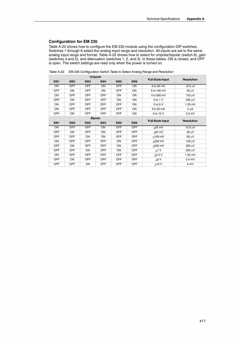
Configuration for EM 235Table A-22 shows how to configure the EM 235 module using the configuration DIP switches.Switches 1 through 6 select the analog input range and resolution. All inputs are set to the sameanalog input range and format. Table A-22 shows how to select for unipolar/bipolar (switch 6), gain(switches 4 and 5), and attenuation (switches 1, 2, and 3). In these tables, ON is closed, and OFFis open. The switch settings are read only when the power is turned on.
Table A-22 EM 235 Configuration Switch Table to Select Analog Range and Resolution
UnipolarFull Scale Input Resolution
SW1 SW2 SW3 SW4 SW5 SW6Full-Scale Input Resolution
ON OFF OFF ON OFF ON 0 to 50 mV 12.5 mV
OFF ON OFF ON OFF ON 0 to 100 mV 25 mV
ON OFF OFF OFF ON ON 0 to 500mV 125 mV
OFF ON OFF OFF ON ON 0 to 1 V 250 mV
ON OFF OFF OFF OFF ON 0 to 5 V 1.25 mV
ON OFF OFF OFF OFF ON 0 to 20 mA 5 mA
OFF ON OFF OFF OFF ON 0 to 10 V 2.5 mV
BipolarFull Scale Input Resolution
SW1 SW2 SW3 SW4 SW5 SW6Full-Scale Input Resolution
ON OFF OFF ON OFF OFF +25 mV 12.5 mV
OFF ON OFF ON OFF OFF +50 mV 25 mV
OFF OFF ON ON OFF OFF +100 mV 50 mV
ON OFF OFF OFF ON OFF +250 mV 125 mV
OFF ON OFF OFF ON OFF +500 mV 250 mV
OFF OFF ON OFF ON OFF +1 V 500 mV
ON OFF OFF OFF OFF OFF +2.5 V 1.25 mV
OFF ON OFF OFF OFF OFF +5 V 2.5 mV
OFF OFF ON OFF OFF OFF +10 V 5 mV

S7-200 Programmable Controller System Manual
418
Input Data Word Format for EM 231 and EM 235Figure A-16 shows where the 12-bit data value is placed within the analog input word of the CPU.
15 3MSB LSB
0AIW XX
0
0 0 0
214Data value 12 Bits
Unipolar data
15 3MSB LSB
AIW XX
0
0 0 0Data value 12 Bits
Bipolar data
4
0
Figure A-16 Input Data Word Format for EM 231 and EM 235
TipThe 12 bits of the analog-to-digital converter (ADC) readings are left-justified in the data wordformat. The MSB is the sign bit: zero indicates a positive data word value.
In the unipolar format, the three trailing zeros cause the data word to change by a count of eightfor each one-count change in the ADC value.
In the bipolar format, the four trailing zeros cause the data word to change by a count of sixteenfor each one count change in the ADC value.
Input Block Diagrams for EM 231 and 235
CC
A+
RA
A--
Rloop
C
CC
B+
RB
B--
Rloop
C
CC
C+
RC
C--
Rloop
A=1
A=2
A=3
Input filter MUX 4 to 1
BUFFER
011
A/D Converter
A=4
C
CC
D+
RD
D--
Rloop
GAIN ADJUST
InstrumentationAMP
+
--
EM 231Analog Input, 4 Inputs
CR
R
R
R
R
R
R
R
Figure A-17 Input Block Diagram for the EM 231 Analog Input, 4 Inputs
Technical Specifications Appendix A
419
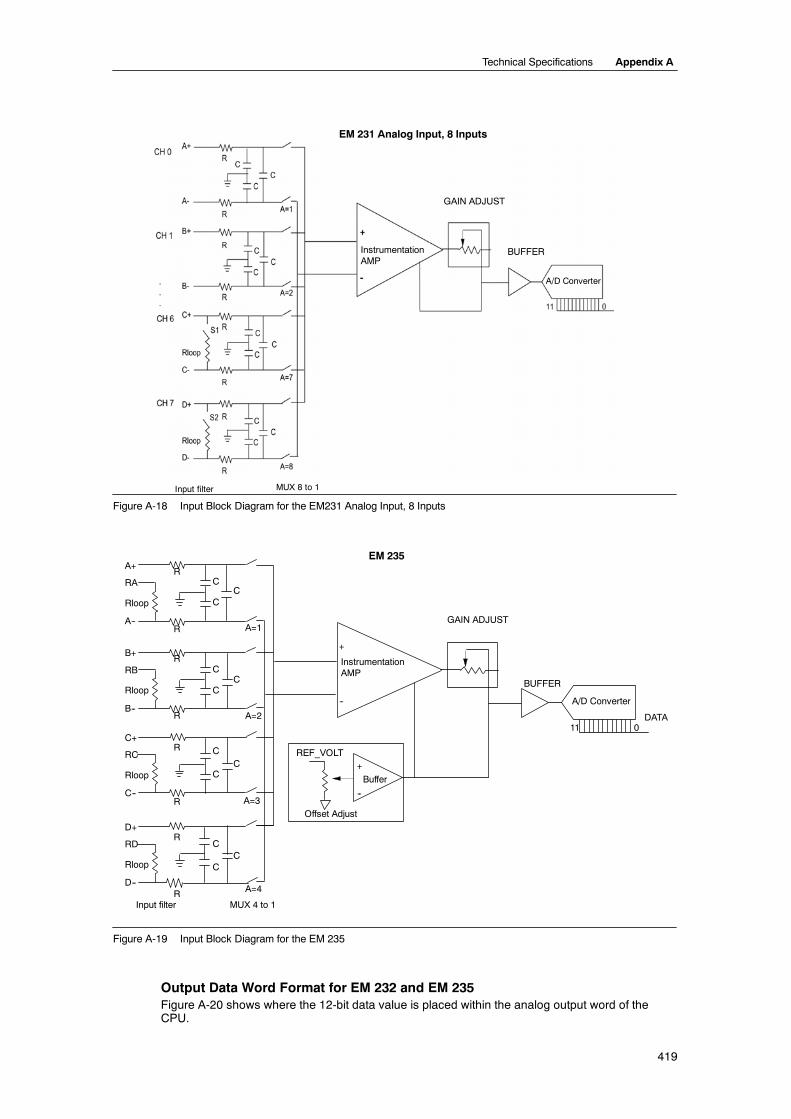
InstrumentationAMP
GAIN ADJUST
BUFFER
A/D Converter
Input filter MUX 8 to 1
EM 231 Analog Input, 8 Inputs
Figure A-18 Input Block Diagram for the EM231 Analog Input, 8 Inputs
REF_VOLT
C
CC
A+
RA
A--
Rloop
C
CC
B+
RB
B--
Rloop
C
CC
C+
RC
C--
Rloop
A=1
A=2
A=3
Buffer
+
--
Input filter MUX 4 to 1
BUFFER
DATA011
A/D Converter
EM 235
A=4
C
CC
D+
RD
D--
Rloop
GAIN ADJUST
InstrumentationAMP
+
--
Offset Adjust
R
R
R
R
R
R
R
R
Figure A-19 Input Block Diagram for the EM 235
Output Data Word Format for EM 232 and EM 235Figure A-20 shows where the 12-bit data value is placed within the analog output word of theCPU.

S7-200 Programmable Controller System Manual
420
15 4MSB LSB
0AQW XX0
0 0 0314
Data value 11 BitsCurrent output data format
15 3MSB LSB
AQW XX0
0 0 0Data value 12 BitsVoltage output data format
40
0
Figure A-20 Output Data Word Format for EM 232 and EM 235
TipThe 12 bits of the digital-to-analog converter (DAC) readings are left-justified in the output dataword format. The MSB is the sign bit: zero indicates a positive data word value. The four trailingzeros are truncated before being loaded into the DAC registers. These bits have no effect on theoutput signal value.
Output Block Diagram for EM 232 and EM 235
DATA 11 0
VrefD/A converter
Digital-to-analog converter
+
--
R
R
Vout--10.. +10 Volts
M
Voltage output buffer
+/-- 2V
+
--
+
--
R
Iout
0..20 mA
100
+24 Volt
Voltage-to-current converter
1/4
R
Figure A-21 Output Block Diagram for the EM 232 and EM 235

Technical Specifications Appendix A
421
Installation GuidelinesUse the following guidelines to ensure accuracy and repeatability:
- Ensure that the 24-VDC Sensor Supply is free of noise and is stable.
- Use the shortest possible sensor wires.
- Use shielded twisted pair wiring for sensor wires.
- Terminate the shield at the Sensor location only.
- Short the inputs for any unused channels, as shown in Figure A-21.
- Avoid bending the wires into sharp angles.
- Use wireways for wire routing.
- Avoid placing signal wires parallel to high-energy wires. If the two wires must meet, crossthem at right angles.
- Ensure that the input signals are within the common mode voltage specification by isolatingthe input signals or referencing them to the external 24V common of the analog module.
TipThe EM 231 and EM 235 expansion modules are not recommended for use withthermocouples.
Understanding the Analog Input Module: Accuracy and RepeatabilityThe EM 231 and EM 235 analog input modules are low-cost, high-speed 12 bit analog inputmodules. The modules can convert an analog signal input to its corresponding digital value in149 µsec. The analog signal input is converted each time your program accesses the analogpoint. These conversion times must be added to the basic execution time of the instruction usedto access the analog input.
The EM 231 and EM 235 provide an unprocesseddigital value (no linearization or filtering) thatcorresponds to the analog voltage or current presentedat the module’s input terminals. Since the modules arehigh-speed modules, they can follow rapid changes inthe analog input signal (including internal and externalnoise).
You can minimize reading-to-reading variations causedby noise for a constant or slowly changing analog inputsignal by averaging a number of readings. Note thatincreasing the number of readings used in computingthe average value results in a correspondingly slower
Repeatability limits(99% of all readings fall within these limits)
Average Value
Mean(average)Accuracy
Signal Input
the average value results in a correspondingly slowerresponse time to changes in the input signal. Figure A-22 Accuracy Definitions
Figure A-22 shows the 99% repeatability limits, the mean or average value of the individualreadings, and the mean accuracy in a graphical form.
The specifications for repeatability describe the reading-to-reading variations of the module for aninput signal that is not changing. The repeatability specification defines the limits within which 99%of the readings will fall. The repeatability is described in this figure by the bell curve.
The mean accuracy specification describes the average value of the error (the difference betweenthe average value of individual readings and the exact value of the actual analog input signal).
Table A-23 gives the repeatability specifications and the mean accuracy as they relate to each ofthe configurable ranges.

S7-200 Programmable Controller System Manual
422
Definitions of the Analog Specifications- Accuracy: deviation from the expected value on a given point
- Resolution: the effect of an LSB change reflected on the output.
Table A-23 EM 231 and EM 235 Specifications
Full Scale Input Repeatability1 Mean (average) Accuracy1,2,3,4Full Scale InputRange % of Full Scale Counts % of Full Scale Counts
EM 231 Specifications
0 to 5 V
0 to 20 mA ± 24 ± 0.1%
0 to 10 V ± 0.075%
24 0.1%
± 32
± 2.5 V
0.075%
± 48 ± 0 05%
32
± 5 V± 48 ± 0.05%
EM 235 Specifications
0 to 50 mV ± 0.25% ± 80
0 to 100 mV ± 0.2% ± 64
0 to 500 mV
0 to 1 V ± 0.075% ± 24
0 to 5 V
0 0 5%
± 0.05% ± 16
0 to 20 mA
0 05% 6
0 to 10 V
± 25 mV ± 0.25% ± 160
± 50 mV ± 0.2% ± 128
± 100 mV ± 0.1% ± 64
± 250 mV
± 500 mV ± 0.075% ± 48± 1 V
± 0.075% ± 48
± 0 05% ± 32± 2.5 V
± 0.05% ± 32
± 5 V
± 10 V
1 Measurements made after the selected input range has been calibrated.2 The offset error in the signal near zero analog input is not corrected, and is not included in the accuracy specifications.3 There is a channel-to-channel carryover conversion error, due to the finite settling time of the analog multiplexer. The maximum carryover
error is 0.1% of the difference between channels.4 Mean accuracy includes effects of non-linearity and drift from 0 to 55 degrees C.

Technical Specifications Appendix A
423
Thermocouple and RTD Expansion Modules Specifications
Table A-24 Thermocouple and RTD Modules Order Numbers
Order Number Expansion Model EM Inputs EM Outputs RemovableConnector
6ES7 231--7PD22--0XA0 EM 231 Analog Input Thermocouple, 4 Inputs 4 Thermocouple -- No
6ES7 231--7PB22--0XA0 EM 231 Analog Input RTD, 2 Inputs 2 RTD -- No
Table A-25 Thermocouple and RTD Modules General Specifications
Order Number Module Name and Description Dimensions (mm)(W x H x D)
Weight Dissipation VDC Requirements+5 VDC +24 VDC
6ES7 231--7PD22--0XA0 EM 231 Analog Input Thermocouple,4 Inputs
71.2 x 80 x 62 210 g 1.8 W 87mA 60 mA
6ES7 231--7PB22--0XA0 EM 231 Analog Input RTD, 2 Inputs 71.2 x 80 x 62 210 g 1.8 W 87 mA 60 mA
Table A-26 Thermocouple and RTD Modules Specifications
General 6ES7 231--7PD22--0XA0Thermocouple
6ES7 231--7PB22--0XA0RTD
IsolationField to logicField to 24 VDC24 VDC to logic
500 VAC500 VAC500 VAC
500 VAC500 VAC500 VAC
Common mode input range(input channel to input channel)
120 VAC 0
Common mode rejection > 120 dB at 120 VAC > 120 dB at 120 VAC
Input type Floating TC Module ground referenced RTD
Input ranges1 TC types (select one per module)S, T, R, E, N, K, JVoltage range : +/-- 80 mV
RTD types (select one per module):platinum (Pt), copper (Cu), nickel (Ni), orResistanceSee Table A-31 for available RTD types.
Input resolutionTemperatureVoltageResistance
0.1° C / 0.1° F15 bits plus sign--
0.1° C / 0.1° F--15 bits plus sign
Measuring Principle Sigma-delta Sigma-delta
Module update time: All channels 405 ms 405 ms (700 ms for Pt10000)
Wire length 100 meters to sensor max. 100 meters to sensor max.
Wire loop resistance 100Ω max. 20Ω, 2.7Ω for Cu max.
Suppression of interference 85 dB at 50 Hz/60 Hz/ 400 Hz 85 dB at 50 Hz/60 Hz/400 Hz
Data word format Voltage: --27648 to + 27648 Resistance: 0 to +27648
Maximum sensor dissipation -- 1m W
Input impedance ≥1 MΩ ≥ 10 MΩ
Maximum input voltage 30 VDC 30 VDC (sense), 5 VDC (source)
Input filter attenuation --3 db at 21 kHz --3 db at 3.6 kHz
Basic error 0.1% FS (voltage) 0.1% FS (resistance)
Repeatability 0.05% FS 0.05% FS
Cold junction error ±1.5 ° C --
24 VDC supply voltage range 20.4 to 28.8 VDC (Class 2, Limited Power, or sensor power from PLC)
1 The input range selection (temperature, voltage on resistance) applies to all channels on the module.

S7-200 Programmable Controller System Manual
424
EM 231AI 2 x RTD
EM 231 Analog Input RTD, 2 Inputs(6ES7 231--7PB22--0XA0)
A+ A -- B+ B-- C+ C-- D+
24 VDCpower
D--
EM 231AI 4
EM 231 Analog Input Thermocouple, 4 Inputs(6ES7 231--7PD22--0XA0)
+ --+-- + +-- --
A+ A -- a+ a-- B+ B-- b+ b--
M L+M L+
+
24 VDCpower
Configuration Configuration
--
+
--
Figure A-23 Connector Terminal Identification for EM 231 Thermocouple and EM 231 RTD Modules
CompatibilityThe RTD and Thermocouple modules are designed to work with the CPU 222, CPU 224,CPU 224XP and CPU 226.
TipThe RTD and Thermocouple modules are designed to give maximum performance wheninstalled in a stable temperature environment.
The EM 231 Thermocouple module, for example, has special cold junction compensationcircuitry that measures the temperature at the module connectors and makes necessarychanges to the measurement to compensate for temperature differences between the referencetemperature and the temperature at the module. If the ambient temperature is changing rapidlyin the area where the EM 231 Thermocouple module is installed, additional errors areintroduced.
To achieve maximum accuracy and repeatability, Siemens recommends that the S7-200 RTDand Thermocouple modules be mounted in locations that have stable ambient temperature.
Noise ImmunityUse shielded wires for best noise immunity. If a thermocouple input channel is not used, short theunused channel inputs, or connect them in parallel to another channel.

Technical Specifications Appendix A
425
EM 231 Thermocouple ModuleThe EM 231 Thermocouple module provides a convenient, isolated interface for the S7-200 familyto seven thermocouple types: J, K, E, N, S, T, and R. It allows the S7-200 to connect to low levelanalog signals, ±80mV range. All thermocouples attached to the module must be of the sametype.
Thermocouple BasicsThermocouples are formed whenever two dissimilar metals are electrically bonded to each other.A voltage is generated that is proportional to the junction temperature. This voltage is small; onemicrovolt could represent many degrees. Measuring the voltage from a thermocouple,compensating for extra junctions, and then linearizing the result forms the basis of temperaturemeasurement using thermocouples.
When you connect a thermocouple to the EM 231 Thermocouple Module, the two dissimilar metalwires are attached to the module at the module signal connector. The place where the twodissimilar wires are attached to each other forms the sensor thermocouple.
Two more thermocouples are formed where the two dissimilar wires are attached to the signalconnector. The connector temperature causes a voltage that adds to the voltage from the sensorthermocouple. If this voltage is not corrected, then the temperature reported will deviate from thesensor temperature.
Cold junction compensation is used to compensate for the connector thermocouple.Thermocouple tables are based on a reference junction temperature, usually zero degreesCelsius. The cold junction compensation compensates the connector to zero degrees Celsius.The cold junction compensation restores the voltage added by the connector thermocouples. Thetemperature of the module is measured internally, then converted to a value to be added to thesensor conversion. The corrected sensor conversion is then linearized using the thermocoupletables.
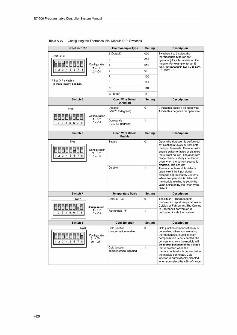
Configuring the EM 231 Thermocouple ModuleConfiguration DIP switches located on the bottom of the module allow you to select thethermocouple type, open wire detect, temperature scale, and cold junction compensation. For theDIP switch settings to take effect, you need to power cycle the PLC and/or the user 24V powersupply.
DIP switch 4 is reserved for future use. Set DIP switch 4 to the 0 (down or off) position. Table A-27shows other DIP switch settings.
S7-200 Programmable Controller System Manual
426
Table A-27 Configuring the Thermocouple Module DIP Switches
Switches 1,2,3 Thermocouple Type Setting Description
SW1, 2, 3J (Default) 000 Switches 1 to 3 select the
thermocouple type (or mVSW1, 2, 3K 001
thermocouple type (or mVoperation) for all channels on the
fConfiguration↑1 On
T 010
p )module. For example, for an Etype, thermocouple SW1 = 0, SW2
1 2 3 4* 5 6 7 8 ↑1 -- On↓0 -- Off E 011
type, thermocouple SW1 = 0, SW2= 1, SW3 = 1.
* S t DIP it h 4
↓
R 100
* Set DIP switch 4to the 0 (down) position.
S 101to the 0 (down) position.
N 110
+/--80mV 111
Switch 5 Open Wire DetectDirection
Setting Description
↑1 O
SW5
Configuration
Upscale(+3276.7 degrees)
0 0 indicates positive on open wire1 indicates negative on open wire
1 2 3 4 5 6 7 8↑1 -- On↓0 -- Off
Co gu at o
Downscale(--3276.8 degrees)
1
Switch 6 Open Wire DetectEnable
Setting Description
1 2 3 4 5 6 7 8↑1 -- On↓0 -- Off
SW6
Configuration
Enable 0 Open wire detection is performedby injecting a 25 µA current ontothe input terminals. The open wireenable switch enables or disablesthe current source. The open wirerange check is always performed,even when the current source isdisabled The EM 231
Disable 1disabled. The EM 231Thermocouple module detectsopen wire if the input signalexceeds approximately ±200mV.When an open wire is detected,the module reading is set to thevalue selected by the Open WireDetect.
Switch 7 Temperature Scale Setting Description
SW7
Configuration
Celsius (_C) 0 The EM 231 Thermocouplemodule can report temperatures inCelsius or Fahrenheit. The Celsiust F h h it i i
1 2 3 4 5 6 7 8↑1 -- On↓0 -- Off
ConfigurationFahrenheit (_F) 1
to Fahrenheit conversion isperformed inside the module.
Switch 8 Cold Junction Setting Description
1 2 3 4 5 6 7 8↑1 -- On↓0 -- Off
SW8
Configuration
Cold junctioncompensation enabled
0 Cold junction compensation mustbe enabled when you are usingthermocouples. If cold junctioncompensation is not enabled, theconversions from the module willbe in error because of the voltage
Cold junctioncompensation disabled
1be in error because of the voltagethat is created when thethermocouple wire is connected tothe module connector. Coldjunction is automatically disabledwhen you select the ±80mV range.

Technical Specifications Appendix A
427
TipH The open wire current source could interfere with signals from some low level sources such
as thermocouple simulators.
H Input voltages exceeding approximately ±200mV will trigger open wire detection even whenthe open wire current source is disabled.
TipH Module error could exceed specifications while the ambient temperature is changing.
H Exceeding the module ambient temperature range specification could cause the modulecold junction to be in error.
Using the Thermocouple: Status IndicatorsThe EM 231 Thermocouple module provides the PLC with data words that indicate temperaturesor error conditions. Status bits indicate range error and user supply/module failure. LEDs indicatethe status of the module. Your program should have logic to detect error conditions and respondappropriately for the application. Table A-28 shows the EM 231 Thermocouple status indicators.
Table A-28 EM 231Thermocouple Status Indicators
Error Condition Channel Data SF LEDRed
24 V LEDGreen
Range Status Bit1 24 VDC UserPower Bad2
No errors Conversion data OFF ON 0 0
24 V missing 32766 OFF OFF 0 1
Open wire and current source enabled --32768/32767 BLINK ON 1 0
Out of range input --32768/32767 BLINK ON 1 0
Diagnostic error3 0000 ON OFF 0 note 3
1 Range status bit is bit 3 in module error register byte (SMB9 for Module 1, SMB11 for Module 2, etc.)2 User Power Bad status bit is bit 2 in module error register byte (SMB 9, SMB 11, etc., refer to Appendix D)3 Diagnostic errors cause a module configuration error. The User Power Bad status bit may or may not be set before the module configuration
error.
TipThe channel data format is two’s complement, 16-bit words. Temperature is presented in 0.1degree units. For example, if the measured temperature is 100.2 degrees, the reported data is1002. Voltage data are scaled to 27648. For example, --60.0mV is reported as --20736(=--60mV/80mV * 27648).
All four channels are updated every 405 milliseconds if the PLC has read the data. If the PLCdoes not read the data within one update time, the module reports old data until the next moduleupdate after the PLC read. To keep channel data current, it is recommended that the PLCprogram read data at least as often as the module update rate.
TipWhen you are using the EM 231 Thermocouple module, you should disable analog filtering inthe PLC. Analog filtering can prevent error conditions from being detected in a timely manner.

S7-200 Programmable Controller System Manual
428
Table A-29 Temperature Ranges (°C) and Accuracy for Thermocouple TypesData Word (1 digit = 0.1_C)
Type J Type K Type T Type E Type R S Type N ¦80mVDec Hex
Type J Type K Type T Type E Type R, S Type N ¦80mV
32767 7FFF >1200.0 _C >1372.0 _C >400.0 _C >1000.0_C >1768.0_C >1300.0_C >94.071mV OF
↑ ↑ ↑ ↑
32511 7EFF 94.071mV
: :
94.071mV
OR
27649 6C01 80.0029mV
27648 6C00 ↑ 80mV
: :
17680 4510 ↑ 1768.0_C
: :NR
13720 3598 1372.0_C ↑NR
: : overrange
13000 32C8 ↑ 1300.0_C 1300.0_C
: :
12000 2EE0 1200.0_C ↑
: :
10000 2710 ↑ 1000.0_C
: :
4000 0FA0 400.0_C 400.0_C
: :
1 0001 0.1_C 0.1_C 0.1_C 0.1_C 0.1_C 0.1_C 0.0029mV
0 0000 0.0_C 0.0_C 0.0_C 0.0_C 0.0_C 0.0_C 0.0mV
--1 FFFF --0.1_C --0.1_C --0.1_C --0.1_C --0.1_C --0.1_C --0.0029mV
: : underrange
--500 FE0C --50.0_C
--1500 FA24 --150.0_C #
: :
--2000 F830 underrange --200.0_C
: :
--2100 F7CC --210.0_C
: :
--2400 F6A0 --240.0_C
: : underrange underrange
--2550 F60A --255.0_C
: : underrange
--2700 F574 # --270.0_C --270.0_C --270.0_C --270.0_CNR
: :NR
--27648 9400 # # # # --80.mV
--27649 93FF --80.0029mV
: :
--32512 8100--94.071mV UR
# # # #
--32768 8000 <--210.0_C <--270.0_C <--270.0_C <--270.0_C <--50.0_C <--270.0_C <--94.071mV UF
Accuracy over full span ±0.1% ±0.3% ±0.6% ±0.3% ±0.6% ±0.4% ±0.1%
Accuracy (normal rangewithout cold junction)
±1.5_C ±1.7_C ±1.4_C ±1.3_C ±3.7_C ±1.6_C ±0.10%
Cold junction error ±1.5_C ±1.5_C ±1.5_C ±1.5_C ±1.5_C ±1.5_C N/A
*OF = Overflow; OR = Overrange; NR = Normal range; UR = Underrange; UF = Underflow
↑ indicates that all analog values greater than this and below the open wire threshold report the overflow data value, 32767 (0x7FFF).# indicates that all analog values less than this and greater than the open wire threshold report the underflow data value, --32768 (0x8000).

Technical Specifications Appendix A
429
Table A-30 Temperature Ranges (°F) for Thermocouple TypesData Word
(1 digit = 0.1°F) Type J Type K Type T Type E Type R, S Type N ¦80 mVDec Hex
Type J Type K Type T Type E Type R, S Type N ¦80 mV
32767 7FFF >2192.0 _F >2502.0 _F >752.0 _F >1832.0_F >3214.0_F >2372.0_F >94.071mV OF
↑ ↑ ↑ ↑ ↑
32511 7EFF 94.071mV
32140 7D90 3214.0_F
94.071mV
OR
27649 6C01 80.0029mV
27648 6C00 ↑
2764.8_F
80mV
NR
: :
25020 61B8 2502.0_F ↑
: : overrangeNR23720 5CA8 ↑ 2372.0_F 2372.0_FNR
: :
21920 55A0 2192.0_F ↑
: :
18320 4790 ↑ 1832.0_F
: :
7520 1D60 752.0_F 752.0_F
: :
320 0140 underrange 32.0_F
: :
1 0001 0.1_F 0.1_F 0.1_F 0.1_F 0.1_F 0.1_F 0.0029mV
0 0000 0.0_F 0.0_F 0.0_F 0.0_F 0.0_F 0.0_F 0.0mV
--1 FFFF --0.1_F --0.1_F --0.1_F --0.1_F --0.1_F --0.1_F --0.0029mV
: :
--580 FDBC --58.0_F
: :
--2380 F6B4 --238.0_F
: :
--3280 F330 underrange --328.0_F underrange
: :
--3460 F27C --346.0_F #
: : underrange
--4000 F060 --400.0_F
: : underrange
--4270 EF52 --427.0_F
: : underrange
--4540 EE44 # --454.0_F --454.0_F --454.0_F --454.0_FNR: : NR
--27648 9400 # # # # --80mV
--27649 93FF --80.0029mV
: :
--32512 8100 --94.071mV OR
# # # #
--3268 8000 <--346.0° F <--454.0° F <--454.0° F <--454.0° F <--58.0° F <--454.0° F <--94.07 mV UF
*OF = Overflow; OR = Overrange; NR = Normal range; UR = Underrange; UF = Underflow↑ indicates that all analog values greater than this and below the open wire threshold report the overflow data value, 32767 (0x7FFF).# indicates that all analog values less than this and greater than the open wire threshold report the underflow data value, --32768 (0x8000).

S7-200 Programmable Controller System Manual
430
EM 231 RTD ModuleThe EM 231 RTD module provides a convenient interface for the S7-200 family to several differentRTDs. It also allows the S7-200 to measure three different resistance ranges. Both RTDsattached to the module must be of the same type.
Configuring the EM 231 RTD ModuleDIP switches enable you to select RTD type, wiringconfiguration, temperature scale, and burnoutdirection. The DIP switches are located on thebottom of the module as shown in this figure. Forthe DIP switch settings to take effect, you need topower cycle the PLC and/or the user 24V powersupply.
Select RTD type by setting DIP switches 1, 2, 3, 4,and 5 to correspond to the RTD as shown in Table
↑1 -- On↓0 -- Off
Configuration
1 2 3 4 5 6 7 8
and 5 to correspond to the RTD as shown in TableA-31. Refer to Table A-32 for other DIP switchsettings.
Figure A-24 DIP Switches for the EM 231RTD Module
Table A-31 Selecting the RTD Type: DIP Switches 1 to 5
RTD Type andAlpha1
SW1 SW2 SW3 SW4 SW5 RTD Type andAlpha1
SW1 SW2 SW3 SW4 SW5
100Ω Pt 0.003850(Default)
0 0 0 0 0 100Ω Pt 0.003902 1 0 0 0 0
200Ω Pt 0.003850 0 0 0 0 1 200Ω Pt 0.003902 1 0 0 0 1
500Ω Pt 0.003850 0 0 0 1 0 500Ω Pt 0.003902 1 0 0 1 0
1000Ω Pt0.003850
0 0 0 1 1 1000Ω Pt0.003902
1 0 0 1 1
100Ω Pt 0.003920 0 0 1 0 0 SPARE 1 0 1 0 0
200Ω Pt 0.003920 0 0 1 0 1 100Ω Ni 0.00672 1 0 1 0 1
500Ω Pt 0.003920 0 0 1 1 0 120Ω Ni 0.00672 1 0 1 1 0
1000Ω Pt0.003920
0 0 1 1 1 1000Ω Ni 0.00672 1 0 1 1 1
100Ω Pt0.00385055
0 1 0 0 0 100Ω Ni 0.006178 1 1 0 0 0
200Ω Pt0.00385055
0 1 0 0 1 120Ω Ni 0.006178 1 1 0 0 1
500Ω Pt0.00385055
0 1 0 1 0 1000Ω Ni0.006178
1 1 0 1 0
1000Ω Pt0.00385055
0 1 0 1 1 10000Ω Pt0.003850
1 1 0 1 1
100Ω Pt 0.003916 0 1 1 0 0 10Ω Cu 0.004270 1 1 1 0 0
200Ω Pt 0.003916 0 1 1 0 1 150Ω FSResistance
1 1 1 0 1
500Ω Pt 0.003916 0 1 1 1 0 300Ω FSResistance
1 1 1 1 0
1000Ω Pt0.003916
0 1 1 1 1 600Ω FSResistance
1 1 1 1 1
1 All RTDs represent 0° C. at the listed resistance except for Cu 10 ohm. Cu 10 ohm is 25° C. at 10 ohm and 0° C. at 9.035 ohm.

Technical Specifications Appendix A
431
Table A-32 Setting RTD DIP Switches
Switch 6 Open Wire Detect/Out of Range
Setting Description
Configuration
SW6 Upscale(+3276.7 degrees)
0 Indicates positive on open wire orout of range
↑1 -- On↓0 -- Off
Configuration
1 2 3 4 5 6 7 8Downscale(--3276.8 degrees)
1 Indicates negative on open wire orout of range
Switch 7 Temperature Scale Setting Description
↑1 On
SW7
Configuration
Celsius (_C) 0 The RTD module can reporttemperatures in Celsius orFahrenheit. The Celsius toF h h it i i
1 2 3 4 5 6 7 8↑1 -- On↓0 -- Off Fahrenheit (_F) 1
Fahrenheit conversion isperformed inside the module.
Switch 8 Wiring Scheme Setting Description
↑1 -- OnConfiguration
SW8 3-wire 0 You can wire the RTD module tothe sensor in three ways (shown inthe figure). The most accurate is 4wire) The least accurate is 2 wire↑1 -- On
↓0 -- Off1 2 3 4 5 6 7 8
2-wire or 4-wire 1wire). The least accurate is 2 wire,which is only recommended iferrors due to wiring can be ignoredin your application.
A+ Sense +
A-- Sense --
a+ Source +
a-- Source --RTD
RTD 4 Wire(most accurate)
A+ Sense +
A-- Sense --
a+ Source +
a-- Source --RTD
If RL1=RL2, error is minimal.
RTD 3 Wire
RL1+RL2=Error
A+ Sense +
A-- Sense --
a+ Source +
a-- Source --RTD
RL1
RL2
Set switch to4-wire mode.
RTD 2 Wire
RL1
RL2
Note: RL1 = Lead resistance from a+ terminal to the RTDRL2 = Lead resistance from a-- terminal to the RTD
RL1
RL2
Figure A-25 Wiring the RTD to the Sensor by 4, 3, and 2 Wire

S7-200 Programmable Controller System Manual
432
EM 231 RTD Status IndicatorsThe RTD module provides the PLC with data words that indicate temperatures or error conditions.Status bits indicate range error and user supply/module failure. LEDs indicate the status of themodule. Your program should have logic to detect error conditions and respond appropriately forthe application. Table A-33 shows the status indicators provided by the EM 231 RTD module.
TipThe channel data format is twos complement, 16-bit words. Temperature is presented in 0.1degree units. (For example, if the measured temperature is 100.2 degrees, the reported data is1002.) Resistance data are scaled to 27648. For example, 75% of full scale resistance isreported as 20736.
(225Ω / 300Ω * 27648 = 20736)
Table A-33 EM 231 RTD Status Indicators
Error Condition Channel Data SF LEDRed
24 V LEDGreen
Range Status Bit1 24 VDC User PowerBad2
No errors Conversion data OFF ON 0 0
24 V missing 32766 OFF OFF 0 1
SW detects open wire --32768/32767 BLINK ON 1 0
Out of range input --32768/32767 BLINK ON 1 0
Diagnostic error3 0000 ON OFF 0 note3
1 Range status bit is bit 3 in module error register byte (SMB9 for Module 1, SMB11 for Module 2, etc.)2 User Power Bad status bit is bit 2 in module error register byte (such as SMB 9, SMB 11, refer to Appendix D.)3 Diagnostic errors cause amodule configuration error. TheUser Power Bad status bitmay ormay not be set before themodule
configuration error.
Channel data is updated every 405 milliseconds, if the PLC has read the data. If the PLC does notread the data within one update time, the module reports old data until the next module updateafter the PLC read. To keep channel data current, it is recommended that the PLC program readdata at least as often as the module update rate.
TipWhen you are using the RTD module, be sure to disable analog filtering in the PLC. Analogfiltering can prevent error conditions from being detected in a timely manner.
Open wire detection is performed by software internal to the RTD module. Out of range inputs anddetected open wire conditions are signaled by setting the range status bit in the SMB and bysetting the channel data up or down scale per the switch settings. Open wire detection takes aminimum of three module scan cycles and can take longer, depending on which wire(s) are open.Open Source+ and/or Source-- wires are detected in the minimum time. Open Sense+ and/orSense-- wires can take 5 seconds or more to detect. Open sense lines can randomly present validdata, with open wire detected intermittently, especially in electrically noisy environments. Electricalnoise can also extend the time it takes to detect the open wire condition. It is recommended thatopen wire/out of range indications be latched in the application program after valid data has beenreported.
TipIf you have an unused channel, you can wire the that channel with a resistor in place of the RTDto prevent open wire detection from causing the SF LED to blink. The resistor must be thenominal value of the RTD. For example, use 100 ohms for PT100 RTD .
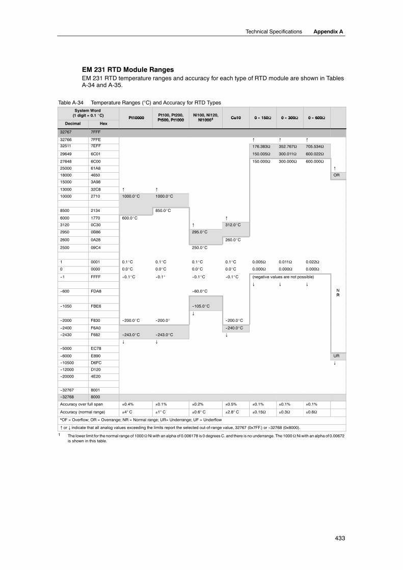
Technical Specifications Appendix A
433
EM 231 RTD Module RangesEM 231 RTD temperature ranges and accuracy for each type of RTD module are shown in TablesA-34 and A-35.
Table A-34 Temperature Ranges (°C) and Accuracy for RTD TypesSystem Word(1 digit = 0.1 _C) Pt10000
Pt100, Pt200,Pt500 Pt1000
Ni100, Ni120,Ni10001 Cu10 0 -- 150Ω 0 -- 300Ω 0 -- 600Ω
Decimal HexPt10000 Pt500, Pt1000 Ni10001 Cu10 0 -- 150Ω 0 -- 300Ω 0 -- 600Ω
32767 7FFF
32766 7FFE ↑ ↑ ↑
32511 7EFF 176.383Ω 352.767Ω 705.534Ω
29649 6C01 150.005Ω 300.011Ω 600.022Ω
27648 6C00 150.000Ω 300.000Ω 600.000Ω
25000 61A8 ↑
18000 4650 OR
15000 3A98
13000 32C8 ↑ ↑
10000 2710 1000.0_C 1000.0_C
8500 2134 850.0_C
6000 1770 600.0_C ↑
3120 0C30 ↑ 312.0_C
2950 0B86 295.0_C
2600 0A28 260.0_C
2500 09C4 250.0_C
1 0001 0.1_C 0.1_C 0.1_C 0.1_C 0.005Ω 0.011Ω 0.022Ω
0 0000 0.0_C 0.0_C 0.0_C 0.0_C 0.000Ω 0.000Ω 0.000Ω
--1 FFFF --0.1_C --0.1_ --0.1_C --0.1_C (negative values are not possible)
↓ ↓ ↓
--600 FDA8 --60.0_C NRR
--1050 FBE6 --105.0_C
↓
--2000 F830 --200.0_C --200.0_ --200.0_C
--2400 F6A0 --240.0_C
--2430 F682 --243.0_C --243.0_C ↓
↓ ↓
--5000 EC78
--6000 E890 UR
--10500 D6FC ↓
--12000 D120
--20000 4E20
--32767 8001
--32768 8000
Accuracy over full span ±0.4% ±0.1% ±0.2% ±0.5% ±0.1% ±0.1% ±0.1%
Accuracy (normal range) ±4° C ±1° C ±0.6° C ±2.8° C ±0.15Ω ±0.3Ω ±0.6Ω
*OF = Overflow; OR = Overrange; NR = Normal range; UR= Underrange; UF = Underflow
↑ or ↓ indicate that all analog values exceeding the limits report the selected out-of-range value, 32767 (0x7FF.) or --32768 (0x8000).
1 The lower limit for the normal rangeof 1000ΩNiwith an alpha of 0.006178 is 0 degreesC. and there is no underrange. The 1000ΩNiwith an alpha of 0.00672is shown in this table.
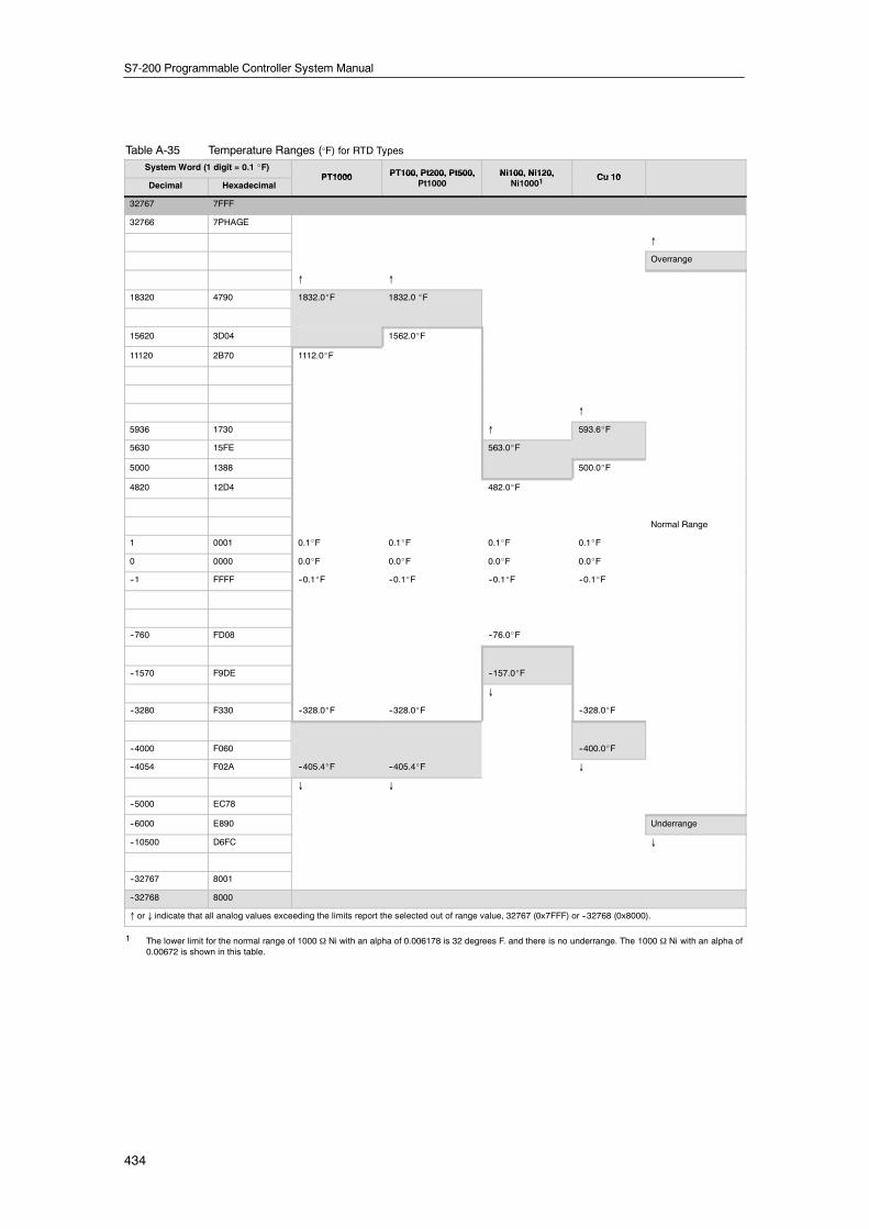
S7-200 Programmable Controller System Manual
434
Table A-35 Temperature Ranges (°F) for RTD Types
System Word (1 digit = 0.1 _F)PT1000 PT100, Pt200, Pt500, Ni100, Ni120, Cu 10
Decimal HexadecimalPT1000 PT100, Pt200, Pt500,
Pt1000Ni100, Ni120,
Ni10001Cu 10
32767 7FFF
32766 7PHAGE
↑
Overrange
↑ ↑
18320 4790 1832.0_F 1832.0 _F
15620 3D04 1562.0_F
11120 2B70 1112.0_F
↑
5936 1730 ↑ 593.6_F
5630 15FE 563.0_F
5000 1388 500.0_F
4820 12D4 482.0_F
Normal Range
1 0001 0.1_F 0.1_F 0.1_F 0.1_F
0 0000 0.0_F 0.0_F 0.0_F 0.0_F
--1 FFFF --0.1_F --0.1_F --0.1_F --0.1_F
--760 FD08 --76.0_F
--1570 F9DE --157.0_F
↓
--3280 F330 --328.0_F --328.0_F --328.0_F
--4000 F060 --400.0_F
--4054 F02A --405.4_F --405.4_F ↓
↓ ↓
--5000 EC78
--6000 E890 Underrange
--10500 D6FC ↓
--32767 8001
--32768 8000
↑ or ↓ indicate that all analog values exceeding the limits report the selected out of range value, 32767 (0x7FFF) or --32768 (0x8000).
1 The lower limit for the normal range of 1000 Ω Ni with an alpha of 0.006178 is 32 degrees F. and there is no underrange. The 1000 Ω Ni with an alpha of0.00672 is shown in this table.

Technical Specifications Appendix A
435
EM 277 PROFIBUS--DP Module Specifications
Table A-36 EM 277 PROFIBUS--DP Module Order Number
Order Number Expansion Model EM Inputs EM Outputs Removable Connector
6ES7 277--0AA22--0XA0 EM 277 PROFIBUS--DP -- -- No
Table A-37 EM 277 PROFIBUS--DP Module General Specifications
Order Number Module Name andDescription
Dimensions (mm)(W x H x D)
Weight Dissipation VDC Requirements+5 VDC +24 VDC
6ES7 277--0AA22--0XA0 EM 277 PROFIBUS--DP 71 x 80 x 62 175 g 2.5 W 150mA See below
Table A-38 EM 277 PROFIBUS--DP Module Specifications
General 6ES7 277--0AA22--0XA0
Number of Ports (Limited Power) 1
Electrical interface RS--485
PROFIBUS--DP/MPI baud rates(set automatically)
9.6, 19.2, 45.45, 93.75, 187.5, and 500 kbaud; 1, 1.5, 3, 6, and12 Mbaud
Protocols PROFIBUS--DP slave and MPI slave
Cable Length
Up to 93.75 kbaud 1200 m
187.5 kbaud 1000 m
500 kbaud 400 m
1 to 1.5 Mbaud 200 m
3 to 12 Mbaud 100 m
Network Capabilities
Station address settings 0 to 99 (set by rotary switches)
Maximum stations per segment 32
Maximum stations per network 126, up to 99 EM 277 stations
MPI Connections 6 total, 2 reserved (1 for PG and 1 for OP)
24 VDC Input Power Requirements
Voltage range 20.4 to 28.8 VDC (Class 2, Limited Power, or sensor power from PLC)
Maximum currentModule only with port activeAdd 90 mA of 5V port loadAdd 120 mA of 24V port load
30 mA60 mA180 mA
Ripple noise (<10 MHz) <1 V peak to peak (maximum)
Isolation (field to logic)1 500 VAC for 1 minute
5 VDC Power on Communications Port
Maximum current per port 90 mA
Isolation (24 VDC to logic) 500 VAC for 1 minute
24 VDC Power on Communications Port
Voltage range 20.4 to 28.8 VDC
Maximum current per port 120 mA
Current limit 0.7 to 2.4 A
Isolation Not isolated, same circuit as input 24 VDC
1 No power is supplied to module logic by the 24 VDC supply. 24 VDC supplies power for the communications port.

S7-200 Programmable Controller System Manual
436
S7-200 CPUs that Support Intelligent ModulesThe EM 277 PROFIBUS--DP slave module is an intelligent expansion module designed to workwith the S7-200 CPUs shown in Table A-39.
Table A-39 EM 277 PROFIBUS--DP Module Compatibility with S7-200 CPUs
CPU Description
CPU 222 Rel. 1.10 or greater CPU 222 DC/DC/DC and CPU 222 AC/DC/Relay
CPU 224 Rel. 1.10 or greater CPU 224 DC/DC/DC and CPU 224 AC/DC/Relay
CPU 224XP Rel. 2.0 or greater CPU 224XP DC/DC/DC and CPU 224XP AC/DC/Relay
CPU 226 Rel. 1.00 or greater CPU 226 DC/DC/DC and CPU 226 AC/DC/Relay
Address Switches and LEDsThe address switches and status LEDs are located on the front of the module as shown in FigureA-26. The pin-out for the DP slave port connector is also shown. See Table A-43 for a descriptionof the status LEDs.
Address Switches:x10=sets the most significant digit of the addressx1= sets the least significant digit of the address
DP Slave Port Connector
Front View of EM 277 PROFIBUS--DP
9-Pin Sub D Connector Pin-out
5
1
9
6
9-pin DFemaleConnector
Pin # Description
1 Chassis ground, tied to the connector shell2 24V Return (same as M on terminal block)3 Isolated Signal B (RxD/TxD+)4 Isolated Request to Send (TTL level)5 Isolated +5V Return6 Isolated +5V (90 mA maximum)7 +24V (120 mA maximum, with reverse
voltage protection diode)8 Isolated Signal A (RxD/TxD--)9 No Connection
Note: Isolated means 500V of isolation fromdigital logic and 24V input power.
Figure A-26 EM 277 PROFIBUS--DP

Technical Specifications Appendix A
437
Distributed Peripheral (DP) Standard CommunicationsPROFIBUS--DP (or DP Standard) is a remote I/O communications protocol defined by theEuropean Standard EN 50170. Devices that adhere to this standard are compatible even thoughthey are manufactured by different companies. DP stands for distributed peripherals, that is,remote I/O. PROFIBUS stands for Process Field Bus.
The EM 277 PROFIBUS--DP module has implemented the DP Standard protocol as defined forslave devices in the following communications protocol standards:
- EN 50 170 (PROFIBUS) describes the bus access and transfer protocol and specifies theproperties of the data transfer medium.
- EN 50 170 (DP Standard) describes the high-speed cyclic exchange of data between DPmasters and DP slaves. This standard defines the procedures for configuration andparameter assignment, explains how cyclic data exchange with distributed I/O functions,and lists the diagnostic options which are supported.
A DP master is configured to know the addresses, slave device types, and any parameterassignment information that the slaves require. The master is also told where to place data that isread from the slaves (inputs) and where to get the data to write to the slaves (outputs). The DPmaster establishes the network and then initializes its DP slave devices. The master writes theparameter assignment information and I/O configuration to the slave. The master then reads thediagnostics from the slave to verify that the DP slave accepted the parameters and the I/Oconfiguration. The master then begins to exchange I/O data with the slave. Each transaction withthe slave writes outputs and reads inputs. The data exchange mode continues indefinitely. Theslave devices can notify the master if there is an exception condition and the master then readsthe diagnostic information from the slave.
Once a DP master has written the parameters and I/O configuration to a DP slave, and the slavehas accepted the parameters and configuration from the master, the master owns that slave. Theslave only accepts write requests from the master that owns it. Other masters on the network canread the slave’s inputs and outputs, but they cannot write anything to the slave.
Using the EM 277 to Connect an S7-200 as a DP SlaveThe S7-200 CPU can be connected to a PROFIBUS--DP network through the EM 277PROFIBUS--DP expansion slave module. The EM 277 is connected to the S7-200 CPU throughthe serial I/O bus. The PROFIBUS network is connected to the EM 277 PROFIBUS--DP modulethrough its DP communications port. This port operates at any PROFIBUS baud rate between9600 baud and 12 Mbaud. See the Specifications for EM 277 PROFIBUS--DP Module for thebaud rates supported.
As a DP slave device, the EM 277 module accepts several different I/O configurations from themaster, allowing you to tailor the amount of data transferred to meet the requirements of theapplication. Unlike many DP devices, the EM 277 module does not transfer only I/O data. Inputs,counter values, timer values, or other calculated values can be transferred to the master by firstmoving the data to the variable memory in the S7-200 CPU. Likewise, data from the master isstored in variable memory in the S7-200 CPU and can be moved to other data areas.

S7-200 Programmable Controller System Manual
438
The DP port of the EM 277 PROFIBUS--DP module can be attached to a DP master on thenetwork and still communicate as an MPI slave with other master devices such as SIMATICprogramming devices or S7-300/S7-400 CPUs on the same network. Figure A-27 shows aPROFIBUS network with a CPU 224 and an EM 277 PROFIBUS--DP module.
- The CPU 315--2 is the DP masterand has been configured by aSIMATIC programming device withSTEP 7 programming software.
- The CPU 224 is a DP slave ownedby the CPU 315--2. The ET 200I/O module is also a slave ownedby the CPU 315--2.
- The S7-400 CPU is attached tothe PROFIBUS network and isreading data from the CPU 224 bymeans of XGET instructions in theS7-400 CPU user program.
ET 200BS7-300 withCPU 315-2 DP
SIMATICprogrammingdevice
CPU 400
CPU 224
EM 277PROFIBUS--DP
Figure A-27 EM 277 PROFIBUS--DP Module and CPU224 on a PROFIBUS Network
Configuration
To use the EM 277 PROFIBUS--DP as aDP slave, you must set the stationaddress of the DP port to match theaddress in the configuration of themaster. The station address is set withthe rotary switches on the EM 277module. You must power cycle the CPUafter you have made a switch change inorder for the new slave address to takeeffect.
The master device exchanges data witheach of its slaves by sending informationfrom its output area to the slave’s outputbuffer (called a “Receive mailbox”). Theslave responds to the message from themaster by returning an input buffer
CPU 224V memory
Offset:5000 bytes
Output buffer(Receive mail-box):16 bytesInput buffer(Send mailbox):16 bytes
CPU 315-2 DPI/O address areas
I/O input area:16 bytes
VB0
VB5000
VB5015VB5016
VB5031
VB5119
VB5032
P000
PI256
PI271
PQ271
VB: variable memory byteP: peripheralPI: peripheral inputPQ: peripheral output
VB4999
EM 277PROFIBUS--DPModule
PQ256I/O output area:16 bytes
y g p(called a “Send mailbox”) which themaster stores in an input area.
Figure A-28 V Memory and I/O Address Area
Figure A-28 shows an example of the V memory and I/O address area of a PROFIBUS--DPMaster.
The EM 277 PROFIBUS--DP can be configured by the DP master to accept output data from themaster and return input data to the master. The output and input data buffers reside in the variablememory (V memory) of the S7-200 CPU. When you configure the DP master, you define the bytelocation in V memory where the output data buffer should start as part of the parameterassignment information for the EM 277. You also define the I/O configuration as the amount ofoutput data to be written to the S7-200 CPU and amount of input data to be returned from theS7-200 CPU. The EM 277 determines the size of the input and output buffers from the I/Oconfiguration. The DP master writes the parameter assignment and I/O configuration informationto the EM 277 PROFIBUS DP module. The EM 277 then transfers the V memory address andinput and output data lengths to the S7-200 CPU.
Figure A-28 shows a memory model of the V memory in a CPU 224 and the I/O address areas ofa DP master CPU. In this example, the DP master has defined an I/O configuration of 16 outputbytes and 16 input bytes, and a V memory offset of 5000. The output buffer and input bufferlengths in the CPU 224 (determined from the I/O configuration) are both 16 bytes long. The outputdata buffer starts at V5000; the input buffer immediately follows the output buffer and begins atV5016. The output data (from the master) is placed in V memory at V5000. The input data (to themaster) is taken from the V memory at V5016.

Technical Specifications Appendix A
439
TipIf you are working with a data unit (consistent data) of three bytes or data units greater than fourbytes, you must use SFC14 to read the inputs of the DP slave and SFC15 to address theoutputs of the DP slave. For more information, see the System Software for S7-300 and S7-400System and Standard Functions Reference Manual.
Table A-40 lists the configurations that are supported by the EM 277 PROFIBUS--DP module. Thedefault configuration for the EM 277 module is two words of input and two words of output.
Table A-40 EM 277 Configuration OptionsConfiguration Inputs to Master Outputs from Master Data Consistency
1 1 word 1 word
2 2 words 2 words
3 4 words 4 words
4 8 words 8 words
5 16 words 16 words
6 32 words 32 wordsWord Consistency
7 8 words 2 wordsWord Consistency
8 16 words 4 words
9 32 words 8 words
10 2 words 8 words
11 4 words 16 words
12 8 words 32 words
13 2 bytes 2 bytes
14 8 bytes 8 bytesByte Consistency
15 32 bytes 32 bytesByte Consistency
16 64 bytes 64 bytes
17 4 bytes 4 bytes
18 8 bytes 8 bytesBuffer Consistency
19 12 bytes 12 bytesBuffer Consistency
20 16 bytes 16 bytes
You can configure the location of the input and output buffers to be anywhere in the V memory ofthe S7-200 CPU. The default address for the input and output buffers is VB0. The location of theinput and output buffers is part of the parameter assignment information that the master writes tothe S7-200 CPU. You configure the master to recognize its slaves and to write the requiredparameters and I/O configuration to each of its slaves.
Use the following tools to configure the DP master:
- For SIMATIC S5 masters, use COM PROFIBUS Windows software
- For SIMATIC S7 masters, use STEP 7 programming software
- For SIMATIC 505 masters, use COM PROFIBUS and either TISOFT2 or SoftShop
For detailed information about using these configuration and programming software packages,refer to the manuals for these devices. For detailed information about the PROFIBUS network andits components, refer to the ET 200 Distributed I/O System Manual.

S7-200 Programmable Controller System Manual
440
Data Consistency
PROFIBUS supports three types of dataconsistency:
- Byte consistency ensures thatbytes are transferred as wholeunits.
- Word consistency ensures thatword transfers cannot beinterrupted by other processes inthe CPU (the two bytes composingthe word are always movedtogether and cannot be split). UseWord consistency if the datavalues being transferred areintegers.
Byte 0Byte 1Byte 2Byte 3
Master Slave
Byte 0Byte 1Byte 2Byte 3
Byte 0Byte 1Byte 2Byte 3Byte 4Byte 5Byte 6Byte 7
Byte consistency
Word consistency
Buffer consistency
Byte 0Byte 1Byte 2Byte 3
Byte 0Byte 1Byte 2Byte 3
Byte 0Byte 1Byte 2Byte 3Byte 4Byte 5Byte 6Byte 7
integers.Figure A-29 Byte, Word, and Buffer Data Consistency
- Buffer consistency ensures that the entire buffer of data is transferred as a single unit,uninterrupted by any other process in the CPU. Buffer consistency should be used if thedata values are double words or floating point values or when a group of values all relate toone calculation or item.
You set the data consistency as part of the I/O configuration in the master. The data consistencyselection is written to the DP slave as part of the initialization of the slave. Both the DP master andthe DP slave use the data consistency selection to be sure that data values (bytes, words, orbuffers) are transferred uninterrupted within master and slave. The different types of consistencyare shown in Figure A-29.
User Program ConsiderationsOnce the EM 277 PROFIBUS--DP module has been successfully configured by a DP master, theEM 277 and the DP master enter data exchange mode. In data exchange mode, the master writesoutput data to the EM 277 PROFIBUS--DP module, the EM 277 module then responds with mostcurrent S7-200 CPU input data. The EM 277 module continuously updates its inputs from theS7-200 CPU in order to provide the most recent input data to the DP Master. The module thentransfers the output data to the S7-200 CPU. The output data from the master is placed into Vmemory (the output buffer) starting at the address that the DP master supplied during initialization.The input data to the master is taken from the V memory locations (the input buffer) immediatelyfollowing the output data.
The output data from the master must be moved by the user program in the S7-200 CPU from theoutput buffer to the data areas where it is to be used. Likewise, the input data to the master mustbe moved from the various data areas to the input buffer for transfer to the master.
Output data from the DP master is placed into V memory immediately after the user programportion of the scan has been executed. Input data (to the master) is copied from V memory to theEM 277 for transfer to the master at the same time.
Output data from the master is only written into V memory when there is new data available fromthe master.
Input data to the master are transmitted to the master on the next data exchange with the master.
The starting address of the data buffers in V memory and the size of the buffers must be known atthe time the user program for the S7-200 CPU is created.
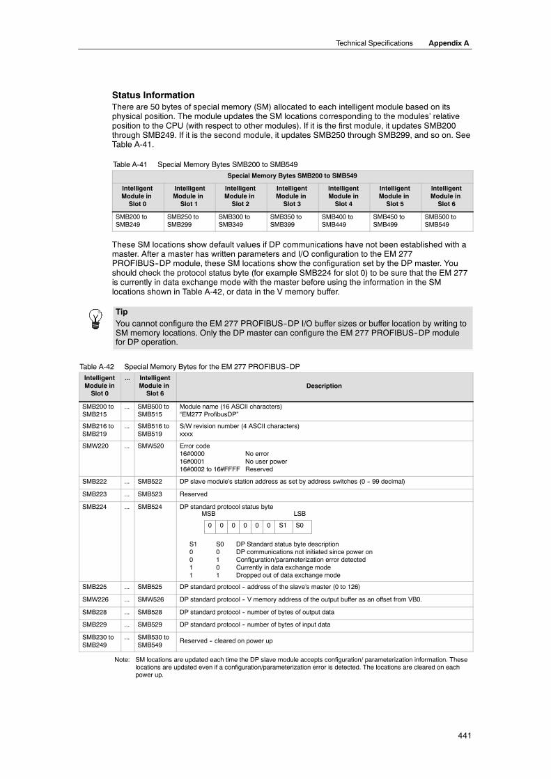
Technical Specifications Appendix A
441
Status InformationThere are 50 bytes of special memory (SM) allocated to each intelligent module based on itsphysical position. The module updates the SM locations corresponding to the modules’ relativeposition to the CPU (with respect to other modules). If it is the first module, it updates SMB200through SMB249. If it is the second module, it updates SMB250 through SMB299, and so on. SeeTable A-41.
Table A-41 Special Memory Bytes SMB200 to SMB549
Special Memory Bytes SMB200 to SMB549
IntelligentModule inSlot 0
IntelligentModule inSlot 1
IntelligentModule inSlot 2
IntelligentModule inSlot 3
IntelligentModule inSlot 4
IntelligentModule inSlot 5
IntelligentModule inSlot 6
SMB200 toSMB249
SMB250 toSMB299
SMB300 toSMB349
SMB350 toSMB399
SMB400 toSMB449
SMB450 toSMB499
SMB500 toSMB549
These SM locations show default values if DP communications have not been established with amaster. After a master has written parameters and I/O configuration to the EM 277PROFIBUS--DP module, these SM locations show the configuration set by the DP master. Youshould check the protocol status byte (for example SMB224 for slot 0) to be sure that the EM 277is currently in data exchange mode with the master before using the information in the SMlocations shown in Table A-42, or data in the V memory buffer.
TipYou cannot configure the EM 277 PROFIBUS--DP I/O buffer sizes or buffer location by writing toSM memory locations. Only the DP master can configure the EM 277 PROFIBUS--DP modulefor DP operation.
Table A-42 Special Memory Bytes for the EM 277 PROFIBUS--DP
IntelligentModule inSlot 0
... IntelligentModule inSlot 6
Description
SMB200 toSMB215
... SMB500 toSMB515
Module name (16 ASCII characters)“EM277 ProfibusDP”
SMB216 toSMB219
... SMB516 toSMB519
S/W revision number (4 ASCII characters)xxxx
SMW220 ... SMW520 Error code16#0000 No error16#0001 No user power16#0002 to 16#FFFF Reserved
SMB222 ... SMB522 DP slave module’s station address as set by address switches (0 -- 99 decimal)
SMB223 ... SMB523 Reserved
SMB224 ... SMB524 DP standard protocol status byte
S1 S0 DP Standard status byte description0 0 DP communications not initiated since power on0 1 Configuration/parameterization error detected1 0 Currently in data exchange mode1 1 Dropped out of data exchange mode
S00 0 0 0 0
MSB LSB
0 S1
SMB225 ... SMB525 DP standard protocol -- address of the slave’s master (0 to 126)
SMW226 ... SMW526 DP standard protocol -- V memory address of the output buffer as an offset from VB0.
SMB228 ... SMB528 DP standard protocol -- number of bytes of output data
SMB229 ... SMB529 DP standard protocol -- number of bytes of input data
SMB230 toSMB249
... SMB530 toSMB549
Reserved -- cleared on power up
Note: SM locations are updated each time the DP slave module accepts configuration/ parameterization information. Theselocations are updated even if a configuration/parameterization error is detected. The locations are cleared on eachpower up.

S7-200 Programmable Controller System Manual
442
LED Status Indicators for the EM 277 PROFIBUS--DPThe EM 277 PROFIBUS--DP module has four status LEDs on the front panel to indicate theoperational state of the DP port:
- After the S7-200 CPU is turned on, the DX MODE LED remains off as long as DPcommunications are not attempted.
- Once DP communications have been successfully initiated (the EM 277 PROFIBUS--DPmodule has entered data exchange mode with the master), the DX MODE LED turns greenand remains on until data exchange mode is exited.
- If DP communications are lost, which forces the EM 277 module to exit data exchangemode, the DX MODE LED turns OFF and the DP ERROR LED turns red. This conditionpersists until the S7-200 CPU is powered off or data exchange is resumed.
- If there is an error in the I/O configuration or parameter information that the DP master iswriting to the EM 277 module, the DP ERROR LED flashes red.
- If user 24 VDC is not provided, the POWER LED will be off.
Table A-43 summarizes the status indications signified by the EM 277 status LEDs.
Table A-43 EM 277 PROFIBUS--DP Module Status LEDsLED OFF RED FLASHING RED GREEN
CPU FAULT Module is good Internal ModuleFailure
---- ----
POWER No 24 VDC User Power ---- ---- 24 VDC User PowerGood
DP ERROR No Error Left Data ExchangeMode
Parameterization/Configuration Error
----
DX MODE Not in Data Exchange Mode ---- ---- In Data ExchangeMode
Note: When the EM 277 PROFIBUS--DP module is used exclusively as an MPI slave, only the green Power LED is on.
Additional Configuration FeaturesThe EM 277 PROFIBUS--DP module can be used as a communications interface to other MPImasters, whether or not it is being used as a PROFIBUS--DP slave. The module can provide aconnection from the S7-300/400 to the S7-200 using the XGET/XPUT functions of theS7-300/400. STEP 7--Micro/WIN and a network card (such as the CP5611) using the MPI orPROFIBUS parameter set, an OP device or the TD 200 (Rel. 2.0 or greater, order number 6ES7272--0AA20--0YA0) can be used to communicate with the S7-200 through the EM 277PROFIBUS--DP module.
A maximum of six connections (six devices) in addition to the DP master can be connected to theEM 277 PROFIBUS--DP module. One connection is reserved for a programming device (PG) andone is reserved for an operator panel (OP). The other four connections can be used by any MPImaster. In order for the EM 277 PROFIBUS--DP module to communicate with multiple masters, allmasters must be operating at the same baud rate. See the Figure A-30 for one possible networkconfiguration.
When the EM 277 PROFIBUS--DP module is used for MPI communications, the MPI master mustuse the station address of the module for all messages that are sent to the S7-200 to which themodule is connected. MPI messages sent to the EM 277 PROFIBUS--DP module are passed onto the S7-200.
The EM 277 PROFIBUS--DP module is a slave module and cannot be used for communicationsbetween S7-200 PLCs using the NETR and NETW functions. The EM 277 PROFIBUS--DPmodule cannot be used for Freeport communications.
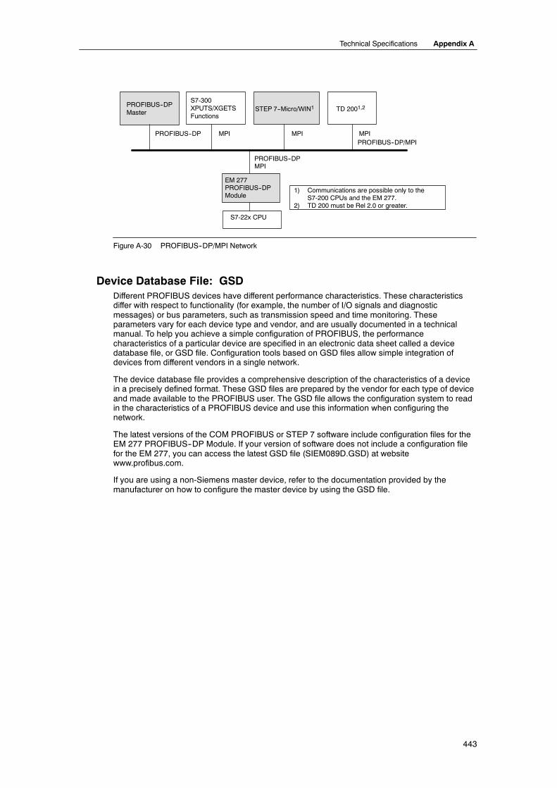
Technical Specifications Appendix A
443
PROFIBUS--DPMaster
MPI MPI
PROFIBUS--DPMPI
PROFIBUS--DP/MPI
S7-300XPUTS/XGETSFunctions
PROFIBUS--DP MPI
STEP 7--Micro/WIN1
EM 277PROFIBUS--DPModule
TD 2001,2
1) Communications are possible only to theS7-200 CPUs and the EM 277.
2) TD 200 must be Rel 2.0 or greater.
S7-22x CPU
Figure A-30 PROFIBUS--DP/MPI Network
Device Database File: GSDDifferent PROFIBUS devices have different performance characteristics. These characteristicsdiffer with respect to functionality (for example, the number of I/O signals and diagnosticmessages) or bus parameters, such as transmission speed and time monitoring. Theseparameters vary for each device type and vendor, and are usually documented in a technicalmanual. To help you achieve a simple configuration of PROFIBUS, the performancecharacteristics of a particular device are specified in an electronic data sheet called a devicedatabase file, or GSD file. Configuration tools based on GSD files allow simple integration ofdevices from different vendors in a single network.
The device database file provides a comprehensive description of the characteristics of a devicein a precisely defined format. These GSD files are prepared by the vendor for each type of deviceand made available to the PROFIBUS user. The GSD file allows the configuration system to readin the characteristics of a PROFIBUS device and use this information when configuring thenetwork.
The latest versions of the COM PROFIBUS or STEP 7 software include configuration files for theEM 277 PROFIBUS--DP Module. If your version of software does not include a configuration filefor the EM 277, you can access the latest GSD file (SIEM089D.GSD) at websitewww.profibus.com.
If you are using a non-Siemens master device, refer to the documentation provided by themanufacturer on how to configure the master device by using the GSD file.

S7-200 Programmable Controller System Manual
444
;================================================; GSD File for the EM 277 PROFIBUS-DP with a DPC31; MLFB : 6ES7 277-0AA2.-0XA0; DATE : 26-March-2001;================================================#Profibus_DP;General parametersGSD_Revision = 1Vendor_Name = ”Siemens”Model_Name = ”EM 277 PROFIBUS-DP”Revision = ”V1.02”Ident_Number = 0x089DProtocol_Ident = 0Station_Type = 0FMS_supp = 0Hardware_Release = ”1.00”Software_Release = ”1.02”9.6_supp = 119.2_supp = 145.45_supp = 193.75_supp = 1187.5_supp = 1500_supp = 11.5M_supp = 13M_supp = 16M_supp = 112M_supp = 1MaxTsdr_9.6 = 60MaxTsdr_19.2 = 60MaxTsdr_45.45 = 250MaxTsdr_93.75 = 60MaxTsdr_187.5 = 60MaxTsdr_500 = 100MaxTsdr_1.5M = 150MaxTsdr_3M = 250MaxTsdr_6M = 450MaxTsdr_12M = 800Redundancy = 0Repeater_Ctrl_Sig = 224V_Pins = 2
; Slave-Specification:OrderNumber=”6ES7 277-0AA2.-0XA0”Periphery=”SIMATIC S5”Slave_Family=10@TdF@SIMATIC
Freeze_Mode_supp = 1Sync_Mode_supp = 1Set_Slave_Add_Supp = 0Auto_Baud_supp = 1Min_Slave_Intervall = 1Fail_Safe = 0Max_Diag_Data_Len = 6Modul_Offset = 0Modular_Station = 1Max_Module = 1Max_Input_len = 128Max_Output_len = 128Max_Data_len = 256
; UserPrmData-DefinitionExtUserPrmData=1 ”I/O Offset in the V-memory”Unsigned16 0 0-10239EndExtUserPrmData; UserPrmData: Length and Preset:User_Prm_Data_Len=3User_Prm_Data= 0,0,0Max_User_Prm_Data_Len=3Ext_User_Prm_Data_Const(0)=0x00,0x00,0x00Ext_User_Prm_Data_Ref(1)=1
;================================================; Continuation of GSD File;================================================
; Module Definition ListModule = ”2 Bytes Out/ 2 Bytes In -” 0x31EndModuleModule = ”8 Bytes Out/ 8 Bytes In -” 0x37EndModuleModule = ”32 Bytes Out/ 32 Bytes In -”0xC0,0x1F,0x1FEndModuleModule = ”64 Bytes Out/ 64 Bytes In -”0xC0,0x3F,0x3FEndModuleModule = ”1 Word Out/ 1 Word In -” 0x70EndModuleModule = ”2 Word Out/ 2 Word In -” 0x71EndModuleModule = ”4 Word Out/ 4 Word In -” 0x73EndModuleModule = ”8 Word Out/ 8 Word In -” 0x77EndModuleModule = ”16 Word Out/ 16 Word In -” 0x7FEndModuleModule = ”32 Word Out/ 32 Word In -”0xC0,0x5F,0x5FEndModuleModule = ”2 Word Out/ 8 Word In -”0xC0,0x41,0x47EndModuleModule = ”4 Word Out/ 16 Word In -”0xC0,0x43,0x4FEndModuleModule = ”8 Word Out/ 32 Word In -”0xC0,0x47,0x5FEndModuleModule = ”8 Word Out/ 2 Word In -”0xC0,0x47,0x41EndModuleModule = ”16 Word Out/ 4 Word In -”0xC0,0x4F,0x43EndModuleModule = ”32 Word Out/ 8 Word In -”0xC0,0x5F,0x47EndModuleModule = ”4 Byte buffer I/O -” 0xB3EndModuleModule = ”8 Byte buffer I/O -” 0xB7EndModuleModule = ”12 Byte buffer I/O -” 0xBBEndModuleModule = ”16 Byte buffer I/O -” 0xBFEndModule
Figure A-31 Listing of the GSD File for the EM 277 PROFIBUS Module

Technical Specifications Appendix A
445
Sample Program for DP Communications to a CPUA sample program in Statement List for the PROFIBUS--DP module in slot 0 for a CPU that usesthe DP port information in SM memory is shown below. The program determines the location ofthe DP buffers from SMW226 and the sizes of the buffers from SMB228 and SMB229. Thisinformation is used to copy the data in the DP output buffer to the process-image output register ofthe CPU. Similarly, the data in the process-image input register of the CPU are copied into the Vmemory input buffer.
In the following sample program for a DP module in position 0, the DP configuration data in theSM memory area provides the configuration of the DP slave. The program uses the following data:
SMW220 DP Module Error StatusSMB224 DP StatusSMB225 Master AddressSMW226 V memory offset of outputsSMB228 Number of bytes of output dataSMB229 Number of bytes of input dataVD1000 Output Data PointerVD1004 Input Data Pointer
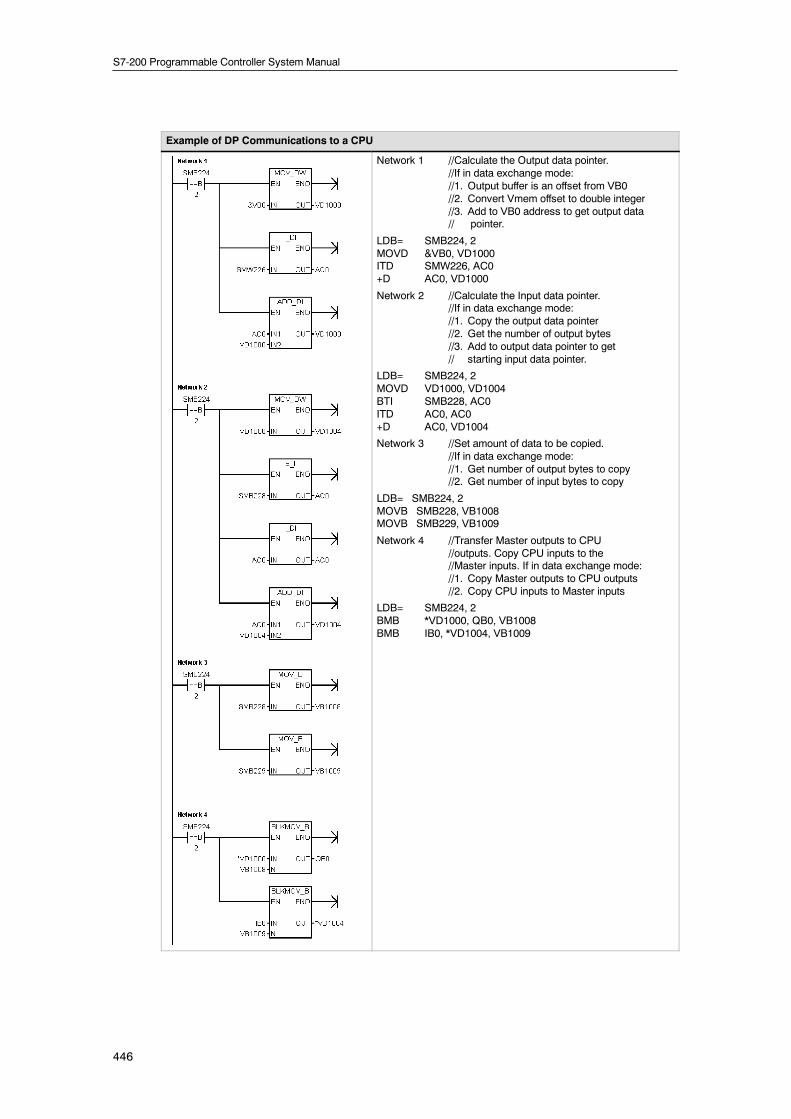
S7-200 Programmable Controller System Manual
446
Example of DP Communications to a CPU
Network 1 //Calculate the Output data pointer.//If in data exchange mode://1. Output buffer is an offset from VB0//2. Convert Vmem offset to double integer//3. Add to VB0 address to get output data// pointer.
LDB= SMB224, 2MOVD &VB0, VD1000ITD SMW226, AC0+D AC0, VD1000
Network 2 //Calculate the Input data pointer.//If in data exchange mode://1. Copy the output data pointer//2. Get the number of output bytes//3. Add to output data pointer to get// starting input data pointer.
LDB= SMB224, 2MOVD VD1000, VD1004BTI SMB228, AC0ITD AC0, AC0+D AC0, VD1004
Network 3 //Set amount of data to be copied.//If in data exchange mode://1. Get number of output bytes to copy//2. Get number of input bytes to copy
LDB= SMB224, 2MOVB SMB228, VB1008MOVB SMB229, VB1009
Network 4 //Transfer Master outputs to CPU//outputs. Copy CPU inputs to the//Master inputs. If in data exchange mode://1. Copy Master outputs to CPU outputs//2. Copy CPU inputs to Master inputs
LDB= SMB224, 2BMB *VD1000, QB0, VB1008BMB IB0, *VD1004, VB1009

Technical Specifications Appendix A
447
EM 241 Modem Module Specifications
Table A-44 EM 241 Modem Module Order Number
Order Number Expansion Model EM Inputs EM Outputs Removable Connector
6ES7 241--1AA22--0XA0 EM 241 Modem Module -- 81 No
1 Eight Q outputs are used as logical controls of the modem function and do not directly control any external signals.
Table A-45 EM 241 Modem Module General Specifications
Order Number Module Name andDescription
Dimensions (mm)(W x H x D)
Weight Dissipation VDC Requirements+5 VDC +24 VDC
6ES7 241--1AA22--0XA0 EM 241 Modem Module 71.2 x 80 x 62 190 g 2.1 W 80 mA 70 mA
Table A-46 EM 241 Modem Module Specifications
General 6ES7 241--1AA22--0XA0
Telephone ConnectionIsolation
(phone line to logic and field power) 1500 VAC (Galvanic)
Physical connection RJ11 (6 position, 4 wire)
Modem standards Bell 103, Bell 212, V.21, V.22, V.22 bis, V.23c, V.32, V.32 bis,V.34 (default)
Security features PasswordCallback
Dialing Pulse or Tone
Messaging Protocols NumericTAP (alphanumeric)UCP commands 1, 30, 51
Industrial Protocols ModbusPPI
24 VDC Input Power Requirements
Voltage rangeIsolation (field power to logic)
20.4 to 28.8 VDC500 VAC for 1 minute
The EM 241 Modem Module replaces thefunction of an external modem connected tothe communications port of the CPU. With anEM 241 installed in your S7-200 system, allyou need to communicate with your CPU froma remote location is a personal computer withan external modem and STEP 7--Micro/WIN.
See Chapter 7, Communicating over aNetwork, for information on configuring. SeeChapter 10, Creating a Program for the ModemModule for programming and advancedfeatures of the module.
You can use the STEP 7--Micro/WIN ModemExpansion Wizard to configure an EM 241Modem Module. See Chapter 10 for moreinformation about the Modem Expansion
Country Code Switch
information about the Modem ExpansionWizard. Figure A-32 EM 241 Modem Module Terminal Block
Diagram
ModemExpansion

S7-200 Programmable Controller System Manual
448
S7-200 CPUs that Support Intelligent ModulesThe EM 241 Modem module is an intelligent expansion module designed to work with the S7-200CPUs shown in Table A-47.
Table A-47 EM 241 Modem Module Compatibility with S7-200 CPUs
CPU Description
CPU 222 Rel. 1.10 or greater CPU 222 DC/DC/DC and CPU 222 AC/DC/Relay
CPU 224 Rel. 1.10 or greater CPU 224 DC/DC/DC and CPU 224 AC/DC/Relay
CPU 224XP Rel 2.0 or greater CPU 224XP DC/DC/DC and CPU 224XP DC/DC/Relay
CPU 226 Rel. 1.00 or greater CPU 226 DC/DC/DC and CPU 226 AC/DC/Relay
Installing the EM 241Follow these steps to install the EM 241:
1. Snap the EM 241 on the DIN rail andplug in the ribbon cable.
2. Connect 24 VDC from the CPU sensorsupply or external source, and connectthe ground terminal to your systemearth ground.
3. Plug the phone line into the RJ11 jack.
4. Set the country code switchesaccording to Table A-48. You must setthe switches before power is applied tothe CPU for the correct country code tobe read.
5. Power the CPU. The green MG(Module Good) light should come on.
Your EM 241 is now ready to communicate.
Table A-48 Country Codes Supported by EM 241
Code Country Telecom Standard
00 Australia ACA TS--002
01 Austria CTR21
02 Belgium CTR21
05 Canada IC CS03
06 China GB3482
08 Denmark CTR21
09 Finland CTR21
10 France CTR21
11 Germany CTR21
12 Greece CTR21
16 Ireland CTR21
18 Italy CTR21
22 Luxembourg CTR21
25 Netherlands CTR21
26 New Zealand PTC 200
27 Norway CTR21
30 Portugal CTR21
34 Spain CTR21
35 Sweden CTR21
36 Switzerland CTR21
38 U.K. CTR21
39 U.S.A. FCC Part 68
RJ11 JackFigure A-33 shows the details of theRJ11 Jack. You can use adaptors toother standard telephone connectors.Refer to your adaptor connectordocumentation for more information.
1 2 3 64 5Pin Description
3 Ring4 Tip
Reverse connection is allowed.
Figure A-33 View of RJ11 Jack
CautionLightning surges or other unexpected high voltages on the telephone line can damage your EM241 Modem Module.
Use a commercially available telephone line surge protector, such as are commonly sold forprotection of personal computer modems. Surge protectors can be damaged as they protectyour EM 241 Modem Module. Choose a surge protector with a positive indicator that shows it isfunctional.
Check your surge protector regularly to ensure that your EM 241 Modem Module continues tobe protected.

Technical Specifications Appendix A
449
EM 253 Position Module Specifications
Table A-49 EM 253 Position Module Order Number
Order Number Expansion Model EM Inputs EM Outputs Removable Connector
6ES7 253--1AA22--0XA0 EM 253 Position Module -- 81 Yes
1 Eight Q outputs are used as logical controls of the motion function and do not directly control any external signals.
Table A-50 EM 253 Position Module General Specifications
Order Number Module Name andDescription
Dimensions (mm)(W x H x D)
Weight Dissipation VDC Requirements+5 VDC +24 VDC
6ES7 253--1AA22--0XA0 EM 253 Position Module 71.2 x 80 x 62 0.190 kg 2.5 W 190 mA See below
Table A-51 EM 253 Position Module Specifications
General 6ES7 253--1AA22--0XA0
Input Features
Number of inputs 5 points
Input typeAll except ZPZP
Sink/Source (IEC Type 1 sink, except ZP)Sink only, current limiting for wide voltage range
Input VoltageMaximum Continuous permissible
STP, RPS, LMT+, LMT--ZP
Surge (all inputs)Rated ValueSTP, RPS, LMT+, LMT--ZP
Logic “1” signal (minimum)STP, RPS, LMT+, LMT--ZP
Logic “0” signal (maximum)STP, RPS, LMT+, LMT--ZP
30 VDC30 VDC at 20 mA, maximum35 VDC for 0.5 sec.
24 VDC at 4 mA, nominal24 VDC at 15 mA, nominal
15 VDC at 2.5 mA, minimum3 VDC at 8.0 mA, minimum
5 VDC at 1 mA, maximum1 VDC at 1 mA, maximum
Isolation (field to logic)Optical Isolation (Galvanic)Isolation groups of
500 VAC for 1 minute1 point for STP, RPS, and ZP2 points for LMT+ and LMT--
Input Delay TimesSTP, RPS, LMT+, LMT--ZP (countable pulse width)
0.2 ms to 12.8 ms, user selectable2 µsec minimum
Connection of 2 Wire Proximity Sensor (Bero)Permissible leakage current 1 mA, maximum
Cable LengthUnshielded
STP, RPS, LMT+, LMT--ZP
ShieldedSTP, RPS, LMT+, LMT--ZP
30 metersNot recommended
100 meters10 meters
Number of inputs on simultaneously All at 55° C (horizontal), All at 45° C (vertical)

S7-200 Programmable Controller System Manual
450
Table A-51 EM 253 Position Module Specifications, continued
6ES7 253--1AA22--0XA0General
Output Features
Number of integrated outputsOutput type
P0+, P0--, P1+, P1--P0, P1, DIS, CLR
6 points (4 signals)
RS422/485 driverOpen drain
Output voltageP0, P1, RS--422 drivers, differential output voltage
Open circuitInto optocoupler diode with 200Ω series resistance
100Ω load54Ω load
P0, P1, DIS, CLR open drainrecommended voltage, open circuitpermissible voltage, open circuit
Sink currentOn state resistance
Off state leakage current, 30 VDCInternal Pull up resistor, output drain to T1
3.5 V typical2.8 V minimum1.5 V minimum1.0 V minimum
5 VDC, available from module30 VDC1
50 mA maximum15Ω maximum10 µA maximum3.3K Ω2
Output currentNumber of output groupsOutputs on simultaneouslyLeakage current per point
P0, P1, DIS, CLROverload Protection
1All at 55° C (horizontal), All at 45° C (vertical)
10 µA maximumNo
Isolation (field to logic)Optical Isolation (Galvanic) 500 VAC for 1 minute
Output delayDIS, CLR: Off to On / On to Off 30 µs, maximum
Pulse distortionP0, P1, outputs, RS--422 drivers, 100 Ω external
loadP0, P1 outputs, open drain, 5 V / 470 Ω external
load
75 ns maximum
300 ns maximum
Switching frequencyP0+, P0--, P1+, P1--, P0 and P1 200 kHz
Cable lengthUnshieldedShielded
Not recommended10 meters
Power Supply
L+ supply voltageLogic supply outputL l t 5 VDC l d
11 to 30 VDC (Class 2, Limited Power, or sensor power from PLC)+5 VDC +/-- 10%, 200 mA maximum
L+ supply current vs. 5 VDC loadLoad current0 mA (no load)200 mA (rated load)
12 VDC Input120 mA300 mA
24 VDC Input70 mA130 mA
IsolationL+ power to logicL+ power to inputsL+ power to outputs
500 VAC for 1 minute500 VAC for 1 minuteNone
Reverse Polarity L+ input and +5V output are diode-protected. Placing a positive voltage on any Mterminal with respect to output point connections can result in potentially damagingcurrent flow.
1 Operation of open drain outputs above 5 VDC may increase radio frequency emissions above permissible limits. Radio frequency containment measuresmay be required for your system or wiring.
2 Depending on your pulse receiver and cable, an additional external pull up resistor may improve pulse signal quality and noise immunity.

Technical Specifications Appendix A
451
S7-200 CPUs that Support Intelligent ModulesThe EM 253 Position module is an intelligent expansion module designed to work with the S7-200CPUs shown in Table A-52.
Table A-52 EM 253 Position Module Compatibility with S7-200 CPUs
CPU Description
CPU 222 Rel. 1.10 or greater CPU 222 DC/DC/DC and CPU 222 AC/DC/Relay
CPU 224 Rel. 1.10 or greater CPU 224 DC/DC/DC and CPU 224 AC/DC/Relay
CPU 224XP Rel 2.0 or greater CPU 224XP DC/DC/DC and CPU 224XP DC/DC/Relay
CPU 226 Rel. 1.00 or greater CPU 226 DC/DC/DC and CPU 226 AC/DC/Relay
EM 253 Position Module Status LEDsThe Status LEDs for the Position Modules are shown in Table A-53.
Table A-53 Position Module Status LEDsLocal I/O LED Color Function Description
-- MF Red Illuminated when module detects a fatal error
-- MG Green Illuminated when there is no module fault, and flashes at 1 Hz rate when aconfiguration error is detected
-- PWR Green Illuminated when 24 VDC is supplied on the L+ and M terminals of the module
Input STP Green Illuminated when the stop input is on
Input RPS Green Illuminated when the reference point switch input is on
Input ZP Green Illuminated when the zero pulse input is on
Input LMT-- Green Illuminated when the negative limit input is on
Input LMT + Green Illuminated when the positive limit input is on
Output P0 Green Illuminated when the P0 output is pulsing
Output P1 Green Illuminated when the P1 output is pulsing or when this output indicates positivemotion
Output DIS Green Illuminated when the DIS output is active
Output CLR Green Illuminated when the clear deviation counter output is active
Figure A-34 EM 253 Position Module

S7-200 Programmable Controller System Manual
452
Wiring DiagramsIn the following schematic figures, the terminals are not in order. See Figure A-34 for terminalarrangement.
P/S 3.3K
3.3K
3.3K
T1
P0
P1
3.3K
DIS
CLR
L+
M
M
P0--
P0+
P1--
P1+
M
STOP5.6K
1M
1K
RPS 5.6K
2M
1K
ZP
3M
LMT+5.6K
1K
LMT--5.6K
4M
1K
+5VDC
Figure A-35 Internal Schematic for the Inputs and Outputs of the EM 253 Position Module
P/S 3.3K
3.3K
3.3K
T1
P0
P1
3.3K
DIS
CLR
L+
M
M
P0--
P0+
P1--
P1+
M
STOP
1M
RPS
2M
ZP
3M
LMT+
LMT-- 5.6K
4M
1K
+5VDC
EM253 Motion Module FM Step Drive
DIR
DIR_N
PULSE
PULSE_N
GATE_N
GND
GND
GND
24V_RTN
ENABLE
ENABLE_N
+24V+24V
24V_RTN
Terminals are not inorder. See FigureA-34 for terminalarrangement.
Figure A-36 Connecting an EM 253 Position Module to a SIMATIC FM Step Drive
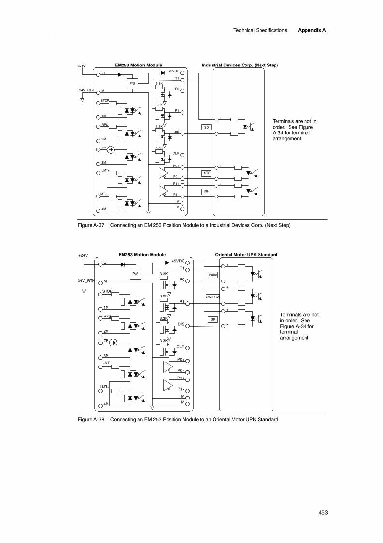
Technical Specifications Appendix A
453
SD
P/S 3.3K
3.3K
3.3K
T1
P0
P1
3.3K
DIS
CLR
L+
M
M
P0--
P0+
P1--
P1+
M
STOP
1M
RPS
2M
ZP
3M
LMT+
LMT--
4M
+5VDC
EM253 Motion Module Industrial Devices Corp. (Next Step)
+
+
+
+24V
24V_RTN
STP
DIR
Terminals are not inorder. See FigureA-34 for terminalarrangement.
Figure A-37 Connecting an EM 253 Position Module to a Industrial Devices Corp. (Next Step)
P/S 3.3K
3.3K
3.3K
T1
P0
P1
3.3KDIS
CLR
L+
M
M
P0--
P0+
P1--
P1+
M
STOP
1M
RPS
2M
ZP
3M
LMT+
LMT--
4M
+5VDC
EM253 Motion Module Oriental Motor UPK Standard
+
SD
+24V
24V_RTN
+
+
--
--
--
Pulse
CW/CCW
Terminals are notin order. SeeFigure A-34 forterminalarrangement.
Figure A-38 Connecting an EM 253 Position Module to an Oriental Motor UPK Standard

S7-200 Programmable Controller System Manual
454
P/S 3.3K
3.3K
3.3K
T1
P0
P1
3.3K
DIS
CLR
L+
M
M
P0--
P0+
P1--
P1+
M
STOP
1M
RPS
2M
ZP
3M
LMT+
LMT--
4M
+5VDC
EM253 Motion Module+24V
24V_RTN
Parker/Compumotor OEM 750
Step
DIR
Terminals are not inorder. See FigureA-34 for terminalarrangement.
DIR
Figure A-39 Connecting an EM 253 Position Module to a Parker/Compumotor OEM 750

Technical Specifications Appendix A
455
(CP 243--1) Ethernet Module Specifications
Table A-54 (CP 243--1) Ethernet Module Order Number
Order Number Expansion Module EM Inputs EM Outputs Removable Connector
6GK7 243--1EX00--OXE0 (CP 243--1) Ethernet Module -- 81 No
1 Eight Q outputs are used as logical controls of Ethernet function and do not directly control any external signals.
Table A-55 (CP 243--1) Ethernet Module General Specifications
Order Number Module Name andDescription
Dimensions (mm)(W x H x D)
Weight Dissipation VDC Requirement+5 VDC +24 VDC
6GK7 243--1EX00--OXE0 (CP 243--1) EthernetModule
71.2 x 80 x 62 approx.150 g
1.75 W 55 mA 60 mA
Table A-56 (CP 243--1) Ethernet Module Specifications
General 6GK7 243--1EX00--0XE0
Transmission Rate 10 Mbits/s and 100 Mbits/s
Flash memory size 1 Mbyte
SDRAM memory size 8 Mbyte
InterfaceConnection to Industrial Ethernet (10/100 Mbit/s) 8-pin RJ45 socket
Input voltage 20.4 to 28.8 VDC
Maximum connections Maximum of 8 S7 connections (XPUT/XGET and READ/WRITE) plus 1 connection toSTEP 7--Micro/WIN per (CP 243--1) Ethernet Module2
Starting time or restart time after a reset Approx. 10 seconds
User data quantities As client: up to 212 bytes for XPUT/XGETAs server: up to 222 bytes for XGET or READ
up to 212 bytes for XPUT or WRITE
2 Only one (CP 243--1) Ethernet module should be connected per S7--200 CPU.
The (CP 243--1) Ethernet module is a communications processor used for connecting the S7-200system to Industrial Ethernet (IE). The S7-200 can be remotely configured, programmed anddiagnosed via Ethernet using STEP 7 Micro/WIN. The S7-200 can communicate with anotherS7--200, S7-300, or S7-400 controller via Ethernet. It can also communicate with an OPC server.
Industrial Ethernet is designed for industry. It can be used with either noise-free industrial twistedpair (ITP) technology, or the Industry-standard twisted pair (TP) technology. Industrial Ethernet canbe implemented to offer a wide range of application specific uses, such as switching, high-speedredundancy, fast connects, and redundant networks. Using the (CP 243--1) Ethernet module, theS7-200 PLC is made compatible with a wide range of existing products that support Ethernet.

S7-200 Programmable Controller System Manual
456
S7-200 CPUs that Support Intelligent ModulesThe (CP 243--1) Ethernet module is an intelligent expansion module designed to work with theS7-200 CPUs shown in Table A-47.
Table A-57 (CP 243--1) Ethernet Module Compatibility with S7-200 CPUs
CPU Description
CPU 222 Rel. 1.10 or greater CPU 222 DC/DC/DC and CPU 222 AC/DC/Relay
CPU 224 Rel. 1.10 or greater CPU 224 DC/DC/DC and CPU 224 AC/DC/Relay
CPU 224XP Rel. 2.00 or greater CPU 224XP DC/DC/DC and CPU 224XP AC/DC/Relay
CPU 226 Rel. 1.00 or greater CPU 226 DC/DC/DC and CPU 226 AC/DC/Relay
The (CP 243--1) Ethernet module is delivered with a preset, unique worldwide MAC address thatcannot be changed.
FunctionsThe (CP 243--1) Ethernet module independently handles data traffic over the Industrial Ethernet.
- Communication is based on TCP/IP
- For communication between S7-200 CPUs and other S7 control systems or PCs viaEthernet, communication services are available as Client and Server. Up to eight connectscan be operated.
- The implementation of PC applications is possible by integration of the S7-OPC Server
- The (CP 243--1) Ethernet module allows direct access of the S7-200 programmingsoftware, STEP 7--Micro/WIN to S7-200 via Ethernet
ConfigurationYou can use the STEP 7--Micro/WIN Ethernet Wizard to configure the (CP 243--1) Ethernetmodule to connect an S7-200 PLC to an Ethernet network. The Ethernet wizard helps you definethe parameters for the (CP 243--1) Ethernet module and then places the configuration instructionsin your project instruction folder. To start the Ethernet Wizard, select the Tools > Ethernet Wizardmenu command. The wizard uses the following information: IP Address, Subnet Mask, GatewayAddress, and communications connection type.
ConnectionsThe (CP 243--1) Ethernet module has thefollowing connections. The connections arelocated under the covers of the front doors.
- Terminal block for 24 VDC supplyvoltage and ground connection
- 8-in RJ45 socket for Ethernetconnection
- Plug connector for I/O bus
- Integrated ribbon cable with socket forI/O bus
Integratedribbon cablewith socketfor I/O bus
8-pin RJ45 socket forEthernet connection
Terminal block for 24VDC supply voltageand ground connection
Connectorfor I/O bus
Figure A-40 Connecting the (CP 243--1) EthernetModule
Additional InformationFor more information about the (CP 243--1) Ethernet module, refer to theSIMATIC NET CP 243--1 Communications Processor for Industrial Ethernet Technical Manual.
Ethernet

Technical Specifications Appendix A
457
(CP 243--1 IT) Internet Module Specifications
Table A-58 (CP 243--1 IT) Internet Module Order Number
Order Number Expansion Module EM Inputs EM Outputs Removable Connector
6GK7 243--1GX00--OXE0 (CP 243--1 IT) Internet Module -- 81 No
1 Eight Q outputs are used as logical controls of the IT function and do not directly control any external signals.
Table A-59 (CP 243--1 IT) Internet Module General Specifications
Order Number Module Name and Description Dimensions (mm)(W x H x D)
Weight Dissipation VDC Requirements+5 VDC +24 VDC
6GK7 243--1GX00--OXE0 (CP 243--1 IT) Internet Module 71.2 x 80 x 62 approx. 150 g 1.75 W 55 mA 60 mA
Table A-60 (CP 243--1 IT) Internet Module Specifications
General 6GK7 243--1GX00--0XE0
Transmission speed 10 Mbit/s and 100 Mbits/s
Flash memory size 8 Mbytes as ROM for firmware of the (CP 243--1 IT) Internet module,8 Mbytes as RAM for the file system
SDRAM memory size 16 Mbyte
Guaranteed life of flash memory for the file system 1 million write or delete operations
InterfaceConnection to Industrial Ethernet (10/100 Mbit/s) 8-pin RJ45 socket
Input voltage 20.4 to 28.8 VDC
Maximum connections Maximum of 8 S7 connections (XPUT/XGET and READ/WRITE) plus 1 connection toSTEP 7--Micro/WIN per (CP 243--1 IT) Internet module1
Maximum number of IT connections 1 for FTP server1 for FTP client1 for e-mail client4 for HTTP connections
Starting time or restart time after a reset Approx. 10 seconds
User data quantities Client: up to 212 bytes for XPUT/XGETServer: up to 222 bytes for XGET or READ
up to 212 bytes for XPUT or WRITE
E--mail size, maximum 1024 characters
File system:Path length including file size and drive namesFile name lengthDirectory nesting depth
254 characters maximum99 characters maximum49 maximum
Server ports available:HTTPFTP command channelFTP data channels for FTP serverS7 connection establishmentS7 server
80213100 to 31991023000 to 3008
1 Only one (CP 243--1 IT) Internet module should be connected per S7--200 CPU.
S7-200 Programmable Controller System Manual
458
The (CP 243--1 IT) Internet module is a communications processor used for connecting theS7-200 system to Industrial Ethernet (IE). The S7-200 can be remotely configured, programmedand diagnosed via Ethernet using STEP 7 Micro/WIN. The S7-200 can communicate with anotherS7--200, S7-300, or S7-400 controller via Ethernet. It can also communicate with an OPC server.
The IT functions of the (CP 243--1 IT) Internet module form the basis for monitoring and, ifnecessary, also manipulating automation systems with a WEB browser from a networked PC.Diagnostic messages can be e-mailed from a system. Using the IT functions, it is easy toexchange entire files with other computer and controller systems.
Industrial Ethernet is the network for the process control level and the cell level of the SIMATICNET open communication system. Physically, Industrial Ethernet is an electrical network based onshielded, coaxial lines, twisted pair cables and an optical network of fiber optic conductors.Industrial Ethernet is defined by the International Standard IEEE 802.3.
S7-200 CPUs that Support Intelligent ModulesThe (CP 243--1 IT) Internet module is an intelligent expansion module designed to work with theS7-200 CPUs shown in Table A-61.
Table A-61 (CP 243--1 IT) Internet Module Compatibility with S7-200 CPUsCPU Description
CPU 222 Rel. 1.10 or greater CPU 222 DC/DC/DC and CPU 222 AC/DC/Relay
CPU 224 Rel. 1.10 or greater CPU 224 DC/DC/DC and CPU 224 AC/DC/Relay
CPU 224XP Rel. 2.00 or greater CPU 224XP DC/DC/DC and CPU 224XP AC/DC/Relay
CPU 226 Rel. 1.00 or greater CPU 226 DC/DC/DC and CPU 226 AC/DC/Relay
The (CP 243--1 IT) Internet module has the following features:
- The (CPU 243--1 IT) Internet module is fully compatible with the (CP 243--1) Ethernetmodule. User programs written for the (CP 243--1) Ethernet module can also be run on the(CP 243--1 IT) Internet module.
The (CP 243--1 1T) Internet module is delivered with a preset, unique worldwide MAC addressthat cannot be changed.
TipOnly one (CP 243--1 IT) Internet module should be connected per S7-200 CPU. If more thanone (CP 243--1 IT) Internet module is connected, the S7-200 CPU may not operate properly.
FunctionsThe (CP 243--1 IT) Internet module offers the following functions:
- S7 Communication is based on TCP/IP
- IT communication
- Configuration
- Watchdog timer
- Ability of preset MAC addresses (48--bit value) to be addressed

Technical Specifications Appendix A
459
ConfigurationYou can use the STEP 7--Micro/WIN Internet Wizard to configure the (CP 243--1 IT) Internetmodule to connect an S7-200 PLC to an Ethernet/Internet network. The (CP 243--1 IT) Internetmodule has additional web server functionality that can be configured with the Internet Wizard. Tostart the Internet Wizard, select the Tools > Internet Wizard menu command.
ConnectionsThe (CP 243--1 IT) Internet module has thefollowing connections. The connections arelocated under the covers of the front doors.
- Terminal block for 24 VDC supplyvoltage and ground connection
- 8-in RJ45 socket for Ethernetconnection
- Plug connector for I/O bus
- Integrated ribbon cable with socket forI/O bus
Integratedribbon cablewith socketfor I/O bus
8-pin RJ45 socket forEthernet connection
Terminal block for 24VDC supply voltageand ground connection
Connectorfor I/O bus
Figure A-41 Connecting the (CP 243--1 IT) InternetModule
Additional Information
For more information about the (CP 243--1 IT) Internet module, refer to theSIMATIC NET CP 243--1 IT Communications Processor for Industrial Ethernet and InformationTechnology Technical Manual.
Internet

S7-200 Programmable Controller System Manual
460
(CP 243--2) AS--Interface Module Specifications
Table A-62 (CP 243--2) AS-Interface Module Order Number
Order Number Expansion Model EM Inputs EM Outputs Removable Connector
6GK7 243--2AX01--0XA0 (CP 243--2) AS--Interface Module 8 Digital and 8 Analog 8 Digital and8 Analog Yes
Table A-63 (CP 243--2) AS-Interface Module General Specifications
Order Number Module Name andDescription
Dimensions (mm)(W x H x D)
Weight DissipationVDC Requirements
+5 VDC FromAS-- Interface
6GK7 243--2AX01--0XA0 (CP 243--2) AS--InterfaceModule
71 x 80 x 62 approx.250 g
3.7 W 220 mA 100 mA
Table A-64 (CP 243--2) AS-Interface Module Specifications
General 6GK7 243--2AX01--0XA0
Cycle time 5 ms with 31 slaves10 ms with 62 AS--I slaves using the extended addressing mode
Configuration Set button on the front panel, or use the total configuration command (refer to thedescription of the AS--I commands in the CP 243--2 AS--I Interface Master manual)
AS--I master profiles supported M1e
Attachment to the AS--I cable Via an S7-200 terminal block. Permitted current loading from terminal 1 to 3 or fromterminal 2 to 4 maximum 3 A.
Address range One digital module with 8 digital inputs and 8 digital outputs, andOne analog module with 8 analog inputs and 8 analog outputs
FeaturesYou can operate up to two AS--Interface modules on the S7-200 at the same time, significantlyincreasing the number of available digital and analog inputs/outputs (maximum 124 digitalinput/124 digital output on AS--Interface per CP). Setup times are reduced because of the ability toconfigure at the touch of a button. LEDs reduce downtime in the event of an error by displayingstatus of the CP and of all connected slaves, and by monitoring AS--Interface main voltage.
The AS--Interface Module has the following features:
- Supports analog modules
- Supports all master functions and allows connections for up to 62 AS--Interface slaves
- LEDs in the front plate display operating status and availability of connected slaves.
- LEDs in the front plate display errors (including AS--Interface voltage error, configurationerror)
- Two terminals allow direct connection of the AS--Interface cable.
- Two buttons display the status information of the slaves, switch operating mode, and adoptthe existing configuration as the SET configuration.
You can use the STEP 7--Micro/WIN AS-i Wizard to configure the (CP 243--2) AS--Interfacemodule. The AS--Interface Wizard helps you use the data from an AS-Interface network in yourconfiguration. To start the AS--i Wizard, select the Tools > AS--i Wizard menu command.AS-i
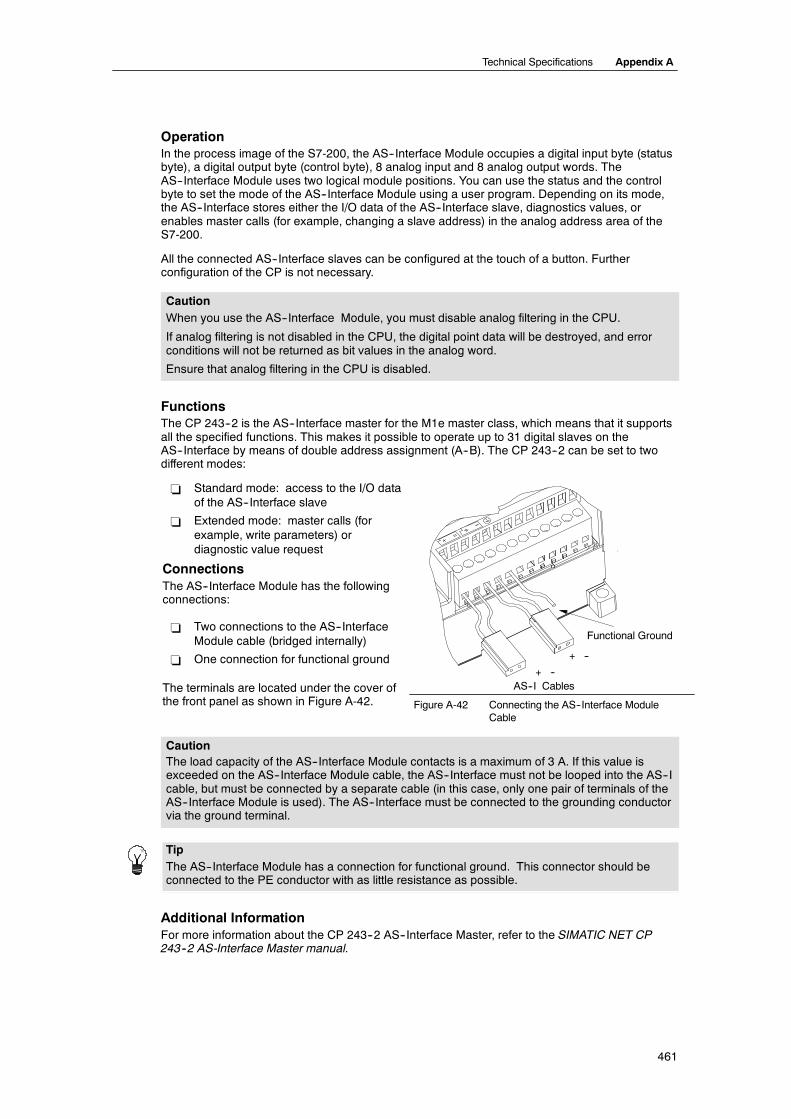
Technical Specifications Appendix A
461
OperationIn the process image of the S7-200, the AS--Interface Module occupies a digital input byte (statusbyte), a digital output byte (control byte), 8 analog input and 8 analog output words. TheAS--Interface Module uses two logical module positions. You can use the status and the controlbyte to set the mode of the AS--Interface Module using a user program. Depending on its mode,the AS--Interface stores either the I/O data of the AS--Interface slave, diagnostics values, orenables master calls (for example, changing a slave address) in the analog address area of theS7-200.
All the connected AS--Interface slaves can be configured at the touch of a button. Furtherconfiguration of the CP is not necessary.
CautionWhen you use the AS--Interface Module, you must disable analog filtering in the CPU.
If analog filtering is not disabled in the CPU, the digital point data will be destroyed, and errorconditions will not be returned as bit values in the analog word.
Ensure that analog filtering in the CPU is disabled.
FunctionsThe CP 243--2 is the AS--Interface master for the M1e master class, which means that it supportsall the specified functions. This makes it possible to operate up to 31 digital slaves on theAS--Interface by means of double address assignment (A--B). The CP 243--2 can be set to twodifferent modes:
- Standard mode: access to the I/O dataof the AS--Interface slave
- Extended mode: master calls (forexample, write parameters) ordiagnostic value request
ConnectionsThe AS--Interface Module has the followingconnections:
- Two connections to the AS--InterfaceModule cable (bridged internally)
- One connection for functional ground
The terminals are located under the cover ofh f l h i Fi A
AS--I Cables
Functional Ground
+ --
+ --
the front panel as shown in Figure A-42. Figure A-42 Connecting the AS--Interface ModuleCable
CautionThe load capacity of the AS--Interface Module contacts is a maximum of 3 A. If this value isexceeded on the AS--Interface Module cable, the AS--Interface must not be looped into the AS--Icable, but must be connected by a separate cable (in this case, only one pair of terminals of theAS--Interface Module is used). The AS--Interface must be connected to the grounding conductorvia the ground terminal.
TipThe AS--Interface Module has a connection for functional ground. This connector should beconnected to the PE conductor with as little resistance as possible.
Additional InformationFor more information about the CP 243--2 AS--Interface Master, refer to the SIMATIC NET CP243--2 AS-Interface Master manual.

S7-200 Programmable Controller System Manual
462
Optional Cartridges
Cartridge Description Order Number
Memory cartridge Memory cartridge, 64K (user program, recipe, and data logging) 6ES7 291--8GF23--0XA0
Memory cartridge Memory cartridge, 256K (user program, recipe, and data logging) 6ES7 291--8GH23--0XA0
Real-Time Clock with battery Clock cartridge accuracy:2 minutes/month at 25°C,7 minutes/month at 0°C to 55°C
6ES7 297--1AA23--0XA0
Battery cartridge Battery cartridge (data retention time): 200 days typical 6ES7 291--8BA20--0XA0
General Features Dimensions
BatterySizeType
3 V, 30 mA hour, Renata CR 10259.9 mm x 2.5 mmLithium < 0.6 g
18 mm
18 mm
10 mm
Memory CartridgeThere are restrictions for using memory cartridges between CPUs of a different model. Memorycartridges programmed in a particular model number CPU can be read by CPUs with the same orhigher model number as shown in Table A-65:
Table A-65 Memory Cartridge Model Number Read Restrictions
Memory Cartridge programmed in a ... Can Be Read By A ...
CPU 221 CPU 221, CPU 222, CPU 224, CPU 224XP and CPU 226
CPU 222 CPU 222, CPU 224, CPU 224XP and CPU 226
CPU 224 CPU 224, CPU 224XP and CPU 226
CPU 224XP CPU 224XP and CPU 226
CPU 226 CPU 226
The 64K and 256K memory cartridges are designed to work only with the new CPUs that have theorder number as shown here: 6ES7 21x--xx23--0XB0. Each “x” means that this digit is a don’tcare.
You may have user programs stored on 32K memory cartridges originally programmed by olderCPUs (version “20”, “21”, or “22”). These cartridges can be read by the new CPUs, subject to themodel number restrictions in Table A-65.
Real Time Clock CartridgeThe Real Time Clock cartridge (6ES7 297--1AA23--0XA0) is designed to work only with the “23”CPUs. The earlier version of the Real Time Clock cartridge (6ES7 297--1AA20--0XA0) is notphysically or electrically compatible with the “23” CPUs.

Technical Specifications Appendix A
463
I/O Expansion Cable
General Features (6ES7 290--6AA20--0XA0)
Cable length 0.8 m
Weight 25 g
Connector type 10 pin ribbon
Female Connector
Male Connector
Figure A-43 Typical Installation of the I/O Expansion Cable
TipOnly one expansion cable is allowed in a CPU/expansion module chain.

S7-200 Programmable Controller System Manual
464
RS-232/PPI Multi-Master Cable and USB/PPI Multi-Master Cable
Table A-66 RS-232/PPI Multi-Master Cable and USB/PPI Multi-Master Cable Specifications
DescriptionOrder Number
S7-200 RS-232/PPI Multi-Master Cable6ES7 901--3CB30--0XA0
S7-200 USB/PPI Multi-Master Cable6ES7--901--3DB30--0XA0
General Characteristics
Supply voltage 14.4 to 28.8 VDC 14.4 to 28.8 VDC
Supply current at 24 V nominal supply 60 mA RMS max. 50 mA RMS max.
Direction change delay: RS-232 stop bit edgereceived to RS-485 transmission disabled
-- --
Isolation RS-485 to RS-232: 500 VDC RS-485 to USB: 500 VDC
RS-485 Side Electrical Characteristics
Common mode voltage range --7 V to +12 V, 1 second, 3 V RMS continuous --7 V to +12 V, 1 second, 3 V RMS continuous
Receiver input impedance 5.4 K Ω min. including termination 5.4 K Ω min. including termination
Termination/bias 10K Ω to +5 V on B, PROFIBUS pin 310K Ω to GND on A, PROFIBUS pin 8
10K Ω to +5 V on B, PROFIBUS pin 310K Ω to GND on A, PROFIBUS pin 8
Receiver threshold/sensitivity +/--0.2 V, 60 mV typical hysteresis +/--0.2 V, 60 mV typical hysteresis
Transmitter differential output voltage 2 V min. at RL=100 Ω,1.5 V min. at RL=54 Ω
2 V min. at RL=100 Ω,1.5 V min. at RL=54 Ω
RS-232 Side Electrical Characteristics
Receiver input impedance 3K Ω min. --
Receiver threshold/sensitivity 0.8 V min. low, 2.4 V max. high0.5 V typical hysteresis
--
Transmitter output voltage +/-- 5 V min. at RL=3K Ω --
USB Side Electrical Characteristics
Full speed (12 MB/s), Human Interface Device (HID)
Supply current at 5V -- 50 mA max.
Power down current -- 400 uA max.
FeaturesThe S7-200 RS-232/PPI Multi-Master Cable comes factory set for optimal performance with theSTEP 7--Micro/WIN 3.2 Service Pack 4 (or later) programming package. The factory setting forthis cable is different than for the PC/PPI cables. Refer to Figure 1 to configure the cable for yourapplication.
You can configure the S7-200 RS-232/PPI Multi-Master Cable to operate the same as the PC/PPIcable and to be compatible with any version of a STEP 7--Micro/WIN programming package bysetting Switch 5 to the PPI/Freeport setting and then selecting your required baud rate.
The USB cable requires STEP 7--Micro/WIN 3.2 Service Pack 4 (or later) programming packagefor operation.
TipFor more information about using these cables, refer to Chapter 7, Communicating over aNetwork.
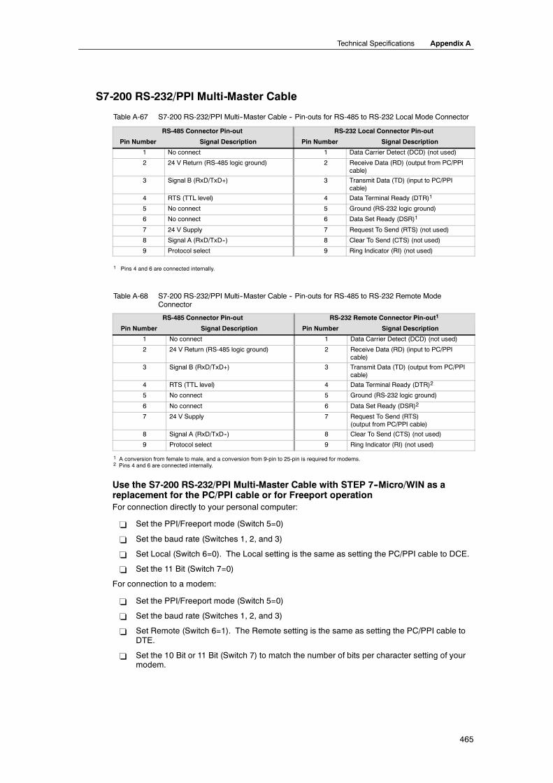
Technical Specifications Appendix A
465
S7-200 RS-232/PPI Multi-Master Cable
Table A-67 S7-200 RS-232/PPI Multi--Master Cable -- Pin-outs for RS-485 to RS-232 Local Mode Connector
RS-485 Connector Pin-out RS-232 Local Connector Pin-out
Pin Number Signal Description Pin Number Signal Description
1 No connect 1 Data Carrier Detect (DCD) (not used)
2 24 V Return (RS-485 logic ground) 2 Receive Data (RD) (output from PC/PPIcable)
3 Signal B (RxD/TxD+) 3 Transmit Data (TD) (input to PC/PPIcable)
4 RTS (TTL level) 4 Data Terminal Ready (DTR)1
5 No connect 5 Ground (RS-232 logic ground)
6 No connect 6 Data Set Ready (DSR)1
7 24 V Supply 7 Request To Send (RTS) (not used)
8 Signal A (RxD/TxD--) 8 Clear To Send (CTS) (not used)
9 Protocol select 9 Ring Indicator (RI) (not used)
1 Pins 4 and 6 are connected internally.
Table A-68 S7-200 RS-232/PPI Multi--Master Cable -- Pin-outs for RS-485 to RS-232 Remote ModeConnector
RS-485 Connector Pin-out RS-232 Remote Connector Pin-out1
Pin Number Signal Description Pin Number Signal Description
1 No connect 1 Data Carrier Detect (DCD) (not used)
2 24 V Return (RS-485 logic ground) 2 Receive Data (RD) (input to PC/PPIcable)
3 Signal B (RxD/TxD+) 3 Transmit Data (TD) (output from PC/PPIcable)
4 RTS (TTL level) 4 Data Terminal Ready (DTR)2
5 No connect 5 Ground (RS-232 logic ground)
6 No connect 6 Data Set Ready (DSR)2
7 24 V Supply 7 Request To Send (RTS)(output from PC/PPI cable)
8 Signal A (RxD/TxD--) 8 Clear To Send (CTS) (not used)
9 Protocol select 9 Ring Indicator (RI) (not used)
1 A conversion from female to male, and a conversion from 9-pin to 25-pin is required for modems.2 Pins 4 and 6 are connected internally.
Use the S7-200 RS-232/PPI Multi-Master Cable with STEP 7--Micro/WIN as areplacement for the PC/PPI cable or for Freeport operationFor connection directly to your personal computer:
- Set the PPI/Freeport mode (Switch 5=0)
- Set the baud rate (Switches 1, 2, and 3)
- Set Local (Switch 6=0). The Local setting is the same as setting the PC/PPI cable to DCE.
- Set the 11 Bit (Switch 7=0)
For connection to a modem:
- Set the PPI/Freeport mode (Switch 5=0)
- Set the baud rate (Switches 1, 2, and 3)
- Set Remote (Switch 6=1). The Remote setting is the same as setting the PC/PPI cable toDTE.
- Set the 10 Bit or 11 Bit (Switch 7) to match the number of bits per character setting of yourmodem.

S7-200 Programmable Controller System Manual
466
Use the S7-200 RS-232/PPI Multi-Master Cable with STEP 7--Micro/WIN 3.2Service Pack 4 (or later)For connection directly to your personal computer:
- Set the PPI mode (Switch 5=1)
- Set Local (Switch 6=0)
- Set 11--bit mode (Switch 7=0)
For connection to a modem:
- Set the PPI mode (Switch 5=1)
- Set Remote (Switch 6=1)
- Set 11--bit mode (Switch 7=0)
TipAll other switches other than those noted above do not matter when using PPI mode.
Figure A-44 shows the S7-200 RS-232/PPI Multi-Master Cable dimensions, label and LEDs.
130 mm
0.8 m
RS-232 COMM RS-485 COMM
4.7 m
Kbaud 123115.2 11057.6 11138.4 00019.2 0019.6 0104.8 0112.4 1001.2 101
8 Spare7 1=10 Bit
0=11 Bit6 1=Remote / DTE
0= Local / DCE5 1=PPI (M Master)
0=PPI/Freeport4 Spare
81 2 3 4 5 6 7 8
10
51 mm
Tx
LED
Rx
PPI
Green
Color
Green
Green
RS-232 transmit indicator
Description
RS-232 receive indicator
RS--485 transmit indicator
Figure A-44 S7-200 RS-232/PPI Multi-Master Cable Dimensions, Label and LEDs

Technical Specifications Appendix A
467
S7-200 USB/PPI Multi-Master CableTo use the USB cable, you must have STEP 7--Micro/WIN 3.2 Service Pack 4 (or later) installed. Itis recommended that you use the USB cable only with an S7-200 CPU22x or later. The USBcable does not support Freeport communications or downloading the TP Designer to the TP070.
Table A-69 S7-200 USB/PPI Multi-Master Cable -- Pin-outs for the RS-485 to USB Series “A” Connector
RS-485 Connector Pin-out USB Connector Pin-out
Pin Number Signal Description Pin Number Signal Description
1 No connect 1 USB -- DataP
2 24 V Return (RS-485 logic ground) 2 USB -- DataM
3 Signal B (RxD/TxD+) 3 USB 5V
4 RTS (TTL level) 4 USB logic ground
5 No connect
6 No connect
7 24 V Supply
8 Signal A (RxD/TxD--)
9 Protocol select (low = 10 bit)
Figure A-45 shows the S7-200 USB/PPI Multi-Master Cable dimensions and LEDs.
130 mm
0.8 m
USB COMM RS-485 COMM
4.7 m
51 mm
Tx
LED
Rx
PPI
Green
Color
Green
Green
USB transmit indicator
Description
USB receive indicator
RS-485 transmit indicator
Figure A-45 S7-200 USB/PPI Multi-Master Cable Dimensions and LEDs

S7-200 Programmable Controller System Manual
468
Input Simulators
Order Number 8 Position Simulator6ES7 274--1XF00--0XA0
14 Position Simulator6ES7 274--1XH00--0XA0
24 Position Simulator6ES7 274--1XK00--0XA0
Size (L x W x D) 61 x 33.5 x 22 mm 91.5 x 35.5 x 22 mm 148.3 x 35.5 x 22 mm
Weight 0.02 Kg 0.03 Kg 0.04 Kg
Points 8 14 24
26 mm
Figure A-46 Installation of the Input Simulator
WarningThese input simulators are not approved for use in Class I DIV 2 or Class I Zone 2 hazardous locations. Theswitches present a potential spark hazard.
Do not use input simulators in Class I DIV 2 or Class I Zone 2 hazardous locations.