S5700-EI Datasheet (Detailed Version) - Proxy...With all these merits, the S5700-EI is widely for...
294
Huawei 5700 Series Switches S5700-EI Datasheet (Detailed Version) Issue 1.0 Date 10-10-2015 HUAWEI TECHNOLOGIES CO., LTD.
Transcript of S5700-EI Datasheet (Detailed Version) - Proxy...With all these merits, the S5700-EI is widely for...

Huawei 5700 Series Switches
S5700-EI Datasheet (Detailed Version)
Issue 1.0
Date 10-10-2015
HUAWEI TECHNOLOGIES CO., LTD.

Issue 1.0 Huawei Proprietary and Confidential
Copyright © Huawei Technologies Co., Ltd. i
Copyright © Huawei Technologies Co., Ltd. 2015. All rights reserved.
No part of this document may be reproduced or transmitted in any form or by any means without prior written consent of Huawei Technologies Co., Ltd.
Trademarks and Permissions
and other Huawei trademarks are trademarks of Huawei Technologies Co., Ltd.
All other trademarks and trade names mentioned in this document are the property of their respective holders.
Notice
The purchased products, services and features are stipulated by the contract made between Huawei and
the customer. All or part of the products, services and features described in this document may not
be within the purchase scope or the usage scope. Unless otherwise specified in the contract, all
statements, information, and recommendations in this document are provided "AS IS" without warranties, guarantees or representations of any kind, either express or implied.
The information in this document is subject to change without notice. Every effort has been made in the
preparation of this document to ensure accuracy of the contents, but all statements, information, and recommendations in this document do not constitute a warranty of any kind, express or implied.
Huawei Technologies Co., Ltd.
Address: Huawei Industrial Base
Bantian, Longgang
Shenzhen 518129
People's Republic of China
Website: http://e.huawei.com

S5700-EI Datasheet
Issue 1.0 Huawei Proprietary and Confidential
Copyright © Huawei Technologies Co., Ltd.
1
1 Introduction
Huawei S5700 series Ethernet switches (S5700 for short) are next-generation energy-saving
Gigabit Ethernet switches that function as the access devices to deliver high bandwidth or
aggregation device for Ethernet multi-service networks. Built on next-generation high-
performance processors and Huawei Versatile Routing Platform (VRP), the S5700 is available
in four series: LI, SI, EI, and HI.
The S5700-EI series enhanced gigabit Ethernet switches (S5700-EI for short) are next-
generation switches that provide flexible GE access ports and 10GE uplink ports. Built on
next-generation high-performance processors and Huawei Versatile Routing Platform (VRP),
the S5700-EI provides large table sizes and higher hardware processing capabilities than
similar switches.Besides, it provides comprehensive service processing capabilities, enhanced
security control, mature IPv6 features, intelligent stack (iStack), allows flexible Ethernet
networking, and is easy to operate and maintain. With all these merits, the S5700-EI is widely
for aggregation/access in enterprise campus networks or gigabit access in data center
networks.
2 Product Overview
2.1 Models and Appearance
Table 2-1 lists all models of S5700-EI and brief description.
Table 2-1 S5700-EI models and description (including S5710-EI and S5720-EI which are part of S5700 EI range of switches)

S5700-EI Datasheet
Issue 1.0 Huawei Proprietary and Confidential
Copyright © Huawei Technologies Co., Ltd.
2
Appearance Description
S5700-28C-EI
24 Ethernet 10/100/1000 ports
Subcards supported: 4x1000Base-X SFP
subcard, 2x10GE SFP+ subcard, and
4x10GE SFP+ subcard
Double hot swappable AC/DC power supplies
Forwarding performance: 96 Mpps
Switching capacity: 256Gbps
S5700-28C-EI-24S
24 Gig SFP ,4 of which are dual-purpose
10/100/1000 or SFP ports
Subcards supported: 4x1000Base-X SFP
subcard, 2x10GE SFP+ subcard, and
4x10GE SFP+ subcard
Double hot swappable AC/DC power
supplies
Forwarding performance: 96 Mpps
Switching capacity: 256Gbps
S5700-28C-PWR-EI
24 Ethernet 10/100/1000 ports
Subcards supported: 4x1000Base-X SFP
subcard, 2x10GE SFP+ subcard, and 4x10GE SFP+ subcard
Double hot swappable AC power supplies
PoE+
Forwarding performance: 96 Mpps
Switching capacity: 256Gbps
S5700-52C-EI
48 Ethernet 10/100/1000 ports
Subcards supported: 4x1000Base-X SFP
subcard, 2x10GE SFP+ subcard, and 4x10GE SFP+ subcard
Double hot swappable AC/DC power
supplies
Forwarding performance: 132 Mpps
Switching capacity: 256Gbps
S5700-52C-PWR-EI
48 Ethernet 10/100/1000 ports
Subcards supported: 4x1000Base-X SFP
subcard, 2x10GE SFP+ subcard, and 4x10GE SFP+ subcard
Double hot swappable AC power supplies
PoE+
Forwarding performance: 132 Mpps
Switching capacity: 256Gbps

S5700-EI Datasheet
Issue 1.0 Huawei Proprietary and Confidential
Copyright © Huawei Technologies Co., Ltd.
3
Appearance Description
S5710-28C-EI
24 Ethernet 10/100/1000 ports,4 of which
are dual-purpose 10/100/1000 or SFP,4 10 Gig SFP+ ports
Subcards supported: 2x10GE SFP+
subcard, 8x10/100/1000BASE-T subcard,
and 8×1000Base-X subcard
Double hot swappable AC/DC power supplies
Forwarding performance: 156Mpps
Switching capacity: 416Gbps
S5710-28C-PWR-EI-AC
24 Ethernet 10/100/1000 ports,4 of which
are dual-purpose 10/100/1000 or SFP,4 10 Gig SFP+ ports
Subcards supported: 2x10GE SFP+
subcard, 8x10/100/1000BASE-T subcard,
and 8×1000Base-X subcard
Double hot swappable AC power supplies, including a 580W AC power
PoE+
Forwarding performance: 156Mpps
Switching capacity: 416Gbps
S5710-52C-EI
48 Ethernet 10/100/1000 ports, 4 10GE
SFP+ ports
Subcards supported: 2x10GE SFP+
subcard, 8x10/100/1000BASE-T subcard,
and 8×1000Base-X subcard
Double hot swappable AC/DC power supplies
Forwarding performance: 192Mpps
Switching capacity: 416Gbps
S5710-52C-PWR-EI-AC
S5710-52C-PWR-EI
48 Ethernet 10/100/1000 ports, 4 10GE
SFP+ ports
Subcards supported: 2x10GE SFP+
subcard, 8x10/100/1000BASE-T subcard,
and 8×1000Base-X subcard
Double hot swappable AC power
supplies( A 580W AC power is included
in S5710-52C-PWR-EI-AC model while no power in S5710-52C-PWR-EI)
PoE+
Forwarding performance: 192Mpps
Switching capacity: 416Gbps

S5700-EI Datasheet
Issue 1.0 Huawei Proprietary and Confidential
Copyright © Huawei Technologies Co., Ltd.
4
Appearance Description
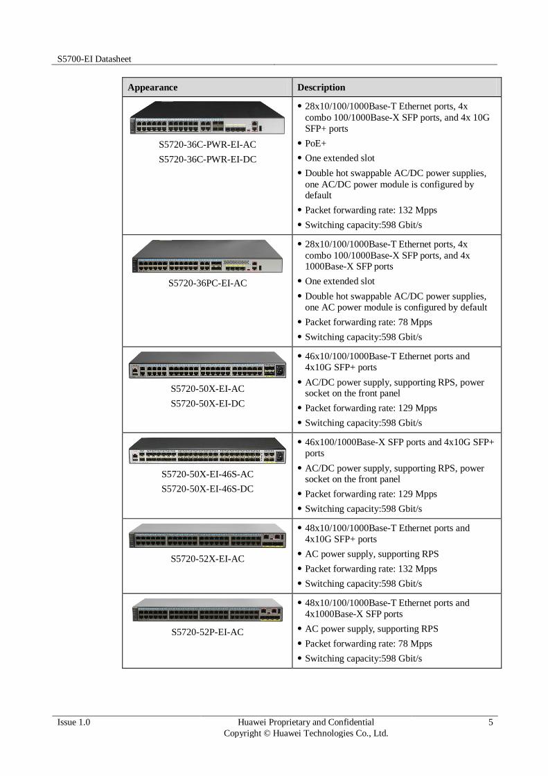
S5720-32P-EI-AC
24x10/100/1000Base-T Ethernet
ports,4x100/1000Base-X SFP ports, and
4x1000Base-X SFP ports
AC power supply, supporting Redundant Power
Supply (RPS), power socket on the front panel
Packet forwarding rate: 48 Mpps
Switching capacity:598 Gbit/s
S5720-32X-EI-AC
S5720-32X-EI-DC
24x10/100/1000Base-T Ethernet ports,
4x100/1000Base-X SFP ports, and 4x10G SFP+ ports
AC/DC power supply, supporting RPS, power socket on the front panel
Packet forwarding rate: 102Mpps
Switching capacity:598 Gbit/s
S5720-32X-EI-24S-AC
S5720-32X-EI-24S-DC
24x100/1000Base-X SFP ports,
4x10/100/1000Base-T Ethernet ports, and 4x10G
SFP+ ports
AC/DC power supply, supporting RPS, power socket on the front panel
Packet forwarding rate: 102 Mpps
Switching capacity:598 Gbit/s
S5720-36C-EI-28S-AC
S5720-36C-EI-28S-DC
28x100/1000Base-X SFP ports, 4x combo
10/100/1000Base-T Ethernet ports, and 4x10G SFP+ ports
One extended slot
Double hot swappable AC/DC power supplies,
one AC/DC power module is configured by default
Packet forwarding rate:132 Mpps
Switching capacity:598 Gbit/s
S5720-36C-EI-AC
S5720-36C-EI-DC
28x10/100/1000Base-T Ethernet ports,4x combo
100/1000Base-X SFP ports, and 4x 10G SFP+ ports
One extended slot
Double hot swappable AC/DC power supplies,
one AC/DC power module is configured by
default
Packet forwarding rate: 132 Mpps
Switching capacity:598 Gbit/s
S5700-EI Datasheet
Issue 1.0 Huawei Proprietary and Confidential
Copyright © Huawei Technologies Co., Ltd.
5
Appearance Description
S5720-36C-PWR-EI-AC
S5720-36C-PWR-EI-DC
28x10/100/1000Base-T Ethernet ports, 4x
combo 100/1000Base-X SFP ports, and 4x 10G
SFP+ ports
PoE+
One extended slot
Double hot swappable AC/DC power supplies,
one AC/DC power module is configured by default
Packet forwarding rate: 132 Mpps
Switching capacity:598 Gbit/s
S5720-36PC-EI-AC
28x10/100/1000Base-T Ethernet ports, 4x
combo 100/1000Base-X SFP ports, and 4x 1000Base-X SFP ports
One extended slot
Double hot swappable AC/DC power supplies,
one AC power module is configured by default
Packet forwarding rate: 78 Mpps
Switching capacity:598 Gbit/s
S5720-50X-EI-AC
S5720-50X-EI-DC
46x10/100/1000Base-T Ethernet ports and
4x10G SFP+ ports
AC/DC power supply, supporting RPS, power socket on the front panel
Packet forwarding rate: 129 Mpps
Switching capacity:598 Gbit/s
S5720-50X-EI-46S-AC
S5720-50X-EI-46S-DC
46x100/1000Base-X SFP ports and 4x10G SFP+
ports
AC/DC power supply, supporting RPS, power socket on the front panel
Packet forwarding rate: 129 Mpps
Switching capacity:598 Gbit/s
S5720-52X-EI-AC
48x10/100/1000Base-T Ethernet ports and
4x10G SFP+ ports
AC power supply, supporting RPS
Packet forwarding rate: 132 Mpps
Switching capacity:598 Gbit/s
S5720-52P-EI-AC
48x10/100/1000Base-T Ethernet ports and
4x1000Base-X SFP ports
AC power supply, supporting RPS
Packet forwarding rate: 78 Mpps
Switching capacity:598 Gbit/s

S5700-EI Datasheet
Issue 1.0 Huawei Proprietary and Confidential
Copyright © Huawei Technologies Co., Ltd.
6
Appearance Description
S5720-56C-EI-48S-AC
S5720-56C-EI-48S-DC
48x100/1000Base-X SFP ports and 4x10G SFP+
ports
One extended slot
Double hot swappable AC/DC power supplies,
one AC/DC power module is configured by
default
Packet forwarding rate: 162 Mpps
Switching capacity:598 Gbit/s
S5720-56C-EI-AC
S5720-56C-EI-DC
48x10/100/1000Base-T Ethernet ports and
4x10G SFP+ ports
One extended slot
Double hot swappable AC/DC power supplies,
one AC/DC power module is configured by default
Packet forwarding rate: 162 Mpps
Switching capacity:598 Gbit/s
S5720-56C-PWR-EI-AC
S5720-56C-PWR-EI-AC1
S5720-56C-PWR-EI-DC
48x10/100/1000Base-T Ethernet ports and
4x10G SFP+ ports
PoE+
One extended slot
Double hot swappable AC/DC power supplies,
one AC/DC power module is configured by default
Packet forwarding rate: 162 Mpps
Switching capacity:598 Gbit/s
S5720-56PC-EI-AC
48x10/100/1000Base-T Ethernet ports and
4x1000Base-X SFP ports
One extended slot
Double hot swappable AC/DC power supplies, one AC power module is configured by default
Packet forwarding rate: 108 Mpps
Switching capacity:598 Gbit/s

S5700-EI Datasheet
Issue 1.0 Huawei Proprietary and Confidential
Copyright © Huawei Technologies Co., Ltd.
7
3 Product Characteristics and Advantages
Powerful support for services
• The S5700-EI supports IGMP v1/v2/v3 snooping, IGMP filter, IGMP fast leave, and IGMP
proxy. It supports line-speed replication of multicast packets between VLANs, multicast load
balancing among member interfaces of a trunk, and controllable multicast, meeting
requirements for IPTV services and other multicast services.
• The S5700-EI provides the Multi-VPN-Instance CE (MCE) function to isolate users in
different VPNs on a device, ensuring data security and reducing costs.
• The S5710-EI supports multiple MPLS & VPN features, including Label Distribution
Protocol (LDP) or Resource Reservation Protocol for Traffic Engineering (RSVP-TE), MPLS
TE, VLL, VPLS, and MPLS L3VPN.
Comprehensive reliability mechanisms
• Besides STP, RSTP, and MSTP, the S5700-EI supports enhanced Ethernet reliability
technologies such as Smart Link and RRPP (Rapid Ring Protection Protocol), which
implement millisecond-level protection switchover and ensure network reliability. It also
provides Smart Link multi-instance and RRPP multiinstance to implement load balancing
among links, optimizing bandwidth usage.
• The S5700-EI supports enhanced trunk (E-Trunk) that enables a CE to be dual-homed to
two PEs (S5700s). E-Trunk greatly enhances link reliability between devices and implements
link aggregation between devices. This improves reliability of access devices.
• The S5700-EI supports the Smart Ethernet Protection (SEP) protocol, a ring network
protocol applied to the link layer on an Ethernet network. SEP can be used on open ring
networks and can be deployed on upper-layer aggregation devices to provide fast switchover
(within 50 ms), ensuring non-stop transmission of services. SEP features simplicity, high
reliability, fast switchover, easy maintenance, and flexible topology, facilitating network
planning and management.
• The S5700-EI supports Ethernet Ring Protection Switching (ERPS), also referred to as
G.8032. As the latest ring network protocol, ERPS was developed based on traditional
Ethernet MAC and bridging functions and uses mature Ethernet OAM function and a Ring
Automatic Protection Switching (R-APS) mechanism to implement millisecond-level
protection switching. ERPS supports various services and allows flexible networking, helping
customers build a network with lower OPEX and CAPEX.
• The S5700-EI supports redundant power supplies, and can use an AC power supply and
a DC power simultaneously. Users can choose a single power supply or use two power
supplies to ensure device reliability.
• The S5700-EI supports VRRP, and can set up VRRP groups with other Layer 3 switches.
VRRP provides redundant routes to ensure stable and reliable communication. Multiple equal-

S5700-EI Datasheet
Issue 1.0 Huawei Proprietary and Confidential
Copyright © Huawei Technologies Co., Ltd.
8
cost routes to an uplink device can be configured on the S5700-EI to provide route
redundancy. When an active route is unreachable, traffic is switched to a backup route.
• The S5700-EI supports Bidirectional Forwarding Detection (BFD) and provides
millisecond-level detection for protocols such as OSPF, IS-IS, VRRP, and PIM to improve
network reliability. The S5700-EI complies with IEEE 802.3ah and 802.1ag. IEEE 802.3ah
defines the mechanism for detecting faults on direct links over the Ethernet in the first mile,
and 802.1ag defines the mechanism for end-to-end service fault detection. The S5700-EI
supports Y.1731. Besides fast end-to-end service fault detection, the S5700-EI can use the
performance measurement tools defined in Y.1731 to monitor network performance,
providing accurate data about network quality.
Well-designed QoS policies and security mechanisms
• The S5700-EI implements complex traffic classification based on packet information such
as the 5-tuple, IP precedence, ToS, DSCP, IP protocol type, ICMP type, TCP/UDP port
number, VLAN ID, Ethernet protocol type. ACLs can be applied to inbound or outbound
direction on an interface. The S5700-EI supports a flow-based two-rate three-color CAR.
Each port supports eight priority queues and multiple queue scheduling algorithms such as
WRR, DRR, SP, WRR+SP, and DRR+SP. All of these ensure the quality of voice, video, and
data services.
• The S5700-EI provides multiple security measures to defend against Denial of Service
(DoS) attacks, and attacks against networks or users. DoS attack types include SYN Flood
attacks, Land attacks, Smurf attacks, and ICMP Flood attacks. Attacks to networks refer to
STP BPDU/root attacks. Attacks to users include bogus DHCP server attacks, man-in-the-
middle attacks, IP/MAC spoofing attacks, DHCP request flood attacks. DoS attacks that
change the CHADDR field in DHCP packets are also attacks against users.
• The S5700-EI supports DHCP snooping, which discards invalid packets that do not match
any binding entries, such as ARP spoofing packets and IP spoofing packets. This prevents
man-in-the-middle attacks to campus networks that hackers initiate by using ARP packets.
The interface connected to a DHCP server can be configured as a trusted interface to protect
the system against bogus DHCP server attacks.
• The S5700-EI supports strict ARP learning, which prevents ARP spoofing attacks that will
exhaust ARP entries. It also provides IP source check to prevent DoS attacks caused by MAC
address spoofing, IP address spoofing, and MAC/IP spoofing.
• The S5700-EI supports 802.1x authentication, MAC address authentication, and combined
authentication on a per port basis, as well as Portal authentication on a per VLANIF interface
basis. The S5700-EI also supports NAC. The S5700-EI authenticates users based on statically
or dynamically bound user information such as the user name, IP address, MAC address,
VLAN ID, access interface, and flag indicating whether antivirus software is installed.
VLANs, QoS policies, and ACLs can be applied to users dynamically.
• The S5700-EI can limit the number of MAC addresses learned on an interface to prevent
attackers from exhausting MAC address entries by using bogus source MAC addresses. This
function minimizes packet flooding that occurs when MAC addresses of users cannot be
found in the MAC address table.
Fine-grained traffic management
• The S5710-EI supports NetStream. The NetStream module supports V5, V8, and V9 packet
formats and provides various traffic analysis functions, such as real-time traffic sampling,
dynamic report generation, traffic attribute analysis, and traffic exception report. The Netstream module enables administrators to monitor network status in real time and provides
applications and analysis functions including potential fault detection, effective fault

S5700-EI Datasheet
Issue 1.0 Huawei Proprietary and Confidential
Copyright © Huawei Technologies Co., Ltd.
9
rectification, fast problem handling, and security monitoring, to help customers optimize
network structure and adjust resource deployment.
• The S5700-EI supports the Sampled Flow (sFlow) function, which uses a sampling
mechanism to obtain statistics about traffic forwarded on a network and sends the statistics to
the Collector in real time. The Collector analyzes traffic statistics to help customers manage
network traffic efficiently. The S5700-EI integrates the sFlow Agent module and uses
hardware for traffic monitoring. Unlike traffic monitoring through port mirroring, sFlow does
not degrade network performance during traffic monitoring.
Easy deployment and maintenance free
• The S5700-EI supports automatic configuration, plug-and-play, and batch remote upgrade.
These capabilities simplify device management and maintenance and reduce maintenance
costs. The S5700-EI supports SNMP v1/v2c/v3 and provides flexible methods for managing
devices. Users can manage the S5700-EI using the CLI and Web NMS. The NQA function
helps users with network planning and upgrading. In addition, the S5700-EI supports NTP,
SSH v2, HWTACACS+, RMON, log hosts, and portbased traffic statistics.
• EasyDeploy: The Commander collects information about the topology of the client
connecting to the Commander and saves client startup information based on the topology. The
client can be replaced without configuration. Configuration and scripts can be delivered to the
client in batches. In addition, the configuration delivery result can be queried. The
Commander can collect and display power consumption on the entire network.
• The S5700-EI supports the GARP VLAN Registration Protocol (GVRP), which
dynamically distributes, registers, and propagates VLAN attributes to reduce manual
configuration workloads of network administrators and to ensure correct VLAN configuration.
In a complex network topology, GVRP simplifies VLAN configuration and reduces network
communication faults caused by incorrect VLAN configuration.
• The S5700-EI supports MUX VLAN. MUX VLAN isolates Layer 2 traffic between
interfaces in a VLAN. Interfaces in a subordinate separate VLAN can communicate with ports
in the principal VLAN but cannot communicate with each other. MUX VLAN is usually used
on an enterprise intranet to isolate user interfaces from each other but allow them to
communicate with server interfaces. This function prevents communication between network
devices connected to certain interfaces or interface groups but allows the devices to
communicate with the default gateway.
PoE function
• The S5700-EI PWR can use PoE power supplies with different power levels to provide -
48V DC power for Powered Devices (PDs) such as IP phones, WLAN APs, and Bluetooth
APs. In its role as Power Sourcing Equipment (PSE), the S5700-EI PWR complies with IEEE
802.3af and 802.3at (PoE+) and can work with PDs that are incompatible with 802.3af or
802.3at. Each port provides a maximum of 30 W power, complying with IEEE 802.3at. The
PoE+ function increases the maximum power of each port and implements intelligent power
management for high-power consumption applications. This facilitates the use of PDs. PoE
ports can work in power-saving mode. The S5700-EI PWR provides improved PoE solutions.
Users can configure whether and when a PoE port supplies power.
High scalability
• The S5700-EI supports intelligent stacking (iStack). Multiple S5700-EI switches can be
connected with stack cables to set up a stack, which functions as a virtual switch. A stack
consists of a master switch, a backup switch, and several slave switches. The backup switch
takes over services when the master switch fails, reducing service interruption time. Stacks support intelligent upgrade so that users do not need to change the software version of a

S5700-EI Datasheet
Issue 1.0 Huawei Proprietary and Confidential
Copyright © Huawei Technologies Co., Ltd.
10
switch when adding it to a stack. The iStack function allows users to connect multiple
switches with stack cables to expand system capacity. These switches can be managed using a
single IP address, which greatly reduces the costs of system expansion, operation, and
maintenance. Compared with traditional networking technologies, iStack has advantages in
scalability, reliability, and system architecture.
Various IPv6 features
• The S5700-EI supports IPv4/IPv6 dual stack and can migrate from an IPv4 network to an
IPv6 network. S5700-EI hardware supports IPv4/IPv6 dual stack, IPv6 over IPv4 tunnels
(including manual tunnels, 6to4 tunnels, and ISATAP tunnels), and Layer 3 line-speed
forwarding. The S5700-EI can be deployed on IPv4 networks, IPv6 networks, or networks
that run both IPv4 and IPv6. This makes networking flexible and enables easy migration from
IPv4 to IPv6.
Huawei S5720-EI series have the following characteristics.
Easy operation and maintenance
The S5720-EI supports Super Virtual Fabric (SVF), which virtualizes the network
architecture consisting of "core/aggregation switches + access switches + APs" into one
device for management. SVF provides the industry's simplest network management
solution, which simplifies device management and enables access switches and wireless
APs to be plug-and-play. SVF Supports profile-based service configuration and
automatic delivery of the configuration on core devices to access devices, implementing
centralized device management and control, easy service configuration, and flexible
configuration adjustment. The S5720-EI functions as a client switch.
The model with prepositive power sockets can be installed in the 300 mm deep cabinet,
and can be maintained through the front panel. This simplifies operation and
maintenance (O&M). The cabinet can be placed against the wall or back to back, meeting requirements of small cabinets and limited equipment room space.
The S5720-EI supports Easy Operation, a solution that provides zero-touch deployment,
replacement of faulty devices without additional configuration, USB-based deployment,
batch configuration, and batch remote upgrade. The Easy Operation solution facilitates
device deployment, upgrade, service provisioning, and other management and
maintenance operations, and also greatly reduces O&M costs. The S5720-EI can be
managed using Simple Network Management Protocol (SNMP) v1, v2c, and v3,
command line interface (CLI), web-based network management system, or Secure Shell
(SSH) v2.0. Additionally, it supports remote network monitoring (RMON), multiple log
hosts, port traffic statistics collection, and network quality analysis, which help in network consolidation and reconstruction.
Powerful service processing capabilities, comprehensive security control
The S5720-EI supports the multi-VPN-instance CE (MCE) function, which allows users
in different VPNs to connect. The switch supports large multi-instance routing tables to
isolate users in different VPNs. Users in multiple VPNs connect to a provider edge (PE)
device through the same physical port on the switch, which reduces the cost on VPN network deployment. The S5720EI also supports MPLS feature in hardware.
The S5720-EI provides excellent quality of service (QoS) capabilities and supports
queue scheduling and congestion control algorithms.it can assign traffic to a queue based
on the MAC address,IP protocol type,and TCP/UDP Ports.Additionally, it adopts
innovative priority queuing and multi-level scheduling mechanisms to implement fine-

S5700-EI Datasheet
Issue 1.0 Huawei Proprietary and Confidential
Copyright © Huawei Technologies Co., Ltd.
11
grained scheduling of data flows, meeting service quality requirements of different user
terminals and services.
With enhanced network admission control (NAC) functions, the S5720-EI supports
802.1x authentication, MAC address authentication, Portal authentication, and hybrid
authentication, and can dynamically delivery user policies such as VLANs, QoS policies,
and access control lists (ACL). It also supports user management based on user groups.
You can specify authentication-free IP network segments and enable redirection of HTTP
connection requests to realize fast deployment of clients. If clients do not support HTTP
access, the S5720-EI can trigger Portal authentication for the clients.
The S5720-EI provides a series of mechanisms to defend against DoS attacks and user-
targeted attacks. DoS attacks are targeted at switches and include SYN flood, Land,
Smurf, and ICMP flood attacks. User-targeted attacks include bogus DHCP server
attacks, IP/MAC address spoofing, DHCP request flood, and change of the DHCP
CHADDR value.
The S5720-EI sets up and maintains a DHCP snooping binding table, and discards the
packets that do not match the table entries. You can specify DHCP snooping trusted and untrusted ports to ensure that users connect only to the authorized DHCP server.
The S5720-EI supports strict ARP learning, which protects a network against from ARP
spoofing attacks to ensure normal network access.
Flexible Ethernet networking
In addition to traditional Spanning Tree Protocol (STP), Rapid Spanning Tree Protocol
(RSTP), and Multiple Spanning Tree Protocol (MSTP), the S5720-EI supports Huawei-
developed Smart Ethernet Protection (SEP) technology and the latest Ethernet Ring
Protection Switching (ERPS) standard. SEP is a ring protection protocol specific to the
Ethernet link layer, and applies to various ring network topologies, such as open ring
topology, closed ring topology, and cascading ring topology. This protocol is reliable,
easy to maintain, and implements fast protection switching. ERPS is defined in ITU-T
G.8032. It implements millisecond-level protection switching based on traditional Ethernet MAC and bridging functions.
The S5720-EI supports Smart Link and Virtual Router Redundancy Protocol
(VRRP), which implement backup of uplinks. One S5720-EI switch can connect to
multiple aggregation switches through multiple links, significantly improving reliability of access devices.
The S5720-EI supports LLDP as a link layer protocol used for interconnected devices to
obtain the connection information of each other. Furthermore,it can support LLDP-MED
to enable the switches to get some layer 2 information of a phone and automatically
allocate certain network parameters including VLAN,policy and QoS and so on to the phone.
In addition, the S5720-EI provides multiple connection fault detection mechanisms,
including Ethernet OAM (IEEE 802.3ah/802.1ag /ITU Y.1731) and Bidirectional
Forwarding Detection (BFD).
Intelligent stack (iStack)
The S5720-EI supports the iStack function that combines multiple switches into a logical
switch. Member switches in a stack implement redundancy backup to improve device
reliability and use inter-device link aggregation to improve link reliability. iStack
provides high network scalability. You can increase ports, bandwidth, and processing
capacity of a stack by simply adding member switches to the stack. iStack also simplifies
device configuration and management. After a stack is set up, up to 9 physical switches
can be virtualized into one logical device. You can log in to any stack member switch to
manage all the member switches in the stack. S5720-EI can join a stack through its dedicated stacking cards for lower latency, and through its service ports that are currently

S5700-EI Datasheet
Issue 1.0 Huawei Proprietary and Confidential
Copyright © Huawei Technologies Co., Ltd.
12
supported by the two 10GE ports on the 2x10G interface cards exclusively for longer
distance connections..
Mature IPv6 technologies
The S5720-EI uses the mature, stable VRP software platform and supports IPv4/IPv6
dual stacks, IPv6 routing protocols (RIPng, OSPFv3, BGP4+, and IS-IS for IPv6), and
IPv6 over IPv4 tunnels including manual, 6-to-4, and Intra-Site Automatic Tunnel
Addressing Protocol (ISATAP) tunnels. With these IPv6 features, the S5720-EI can be
deployed on a pure IPv4 network, a pure IPv6 network, or a shared IPv4/IPv6 network, helping realize IPv4-to-IPv6 transition.
4 Product Specifications
4.1 Functions and Features
Table 4-1 lists the functions and features available on the S5720-EI.
Table 4-1
Table 4-2 Functions and features available on the S5720-EI
Feature Specification
MAC address
table
IEEE 802.1d
64K MAC address entries
MAC address learning and aging
Static, dynamic, and blackhole MAC address entries
Packet filtering based on source MAC addresses
VLAN 4K VLANs
Guest VLAN and voice VLAN
GVRP
MUX VLAN
VLAN assignment based on MAC addresses, protocols,
IP subnets, policies, and ports
1:1 and N:1 VLAN mapping

S5700-EI Datasheet
Issue 1.0 Huawei Proprietary and Confidential
Copyright © Huawei Technologies Co., Ltd.
13
VLAN-based transparent transmission of protocol packets
Jumbo frame 12K
Ring
protection
RRPP ring topology and RRPP multi-instance
Smart Link tree topology and Smart Link multi-
instance, providing millisecond-level protection switchover
Smart Ethernet Protection (SEP),G.8032 Ethernet Ring Protection Switching (ERPS)
STP (IEEE 802.1d), RSTP (IEEE 802.1w), and MSTP (IEEE 802.1s)
BPDU protection, root protection, and loop protection
BPDU tunnel
IP routing Static routing, RIPv1/2, RIPng, OSPF, OSPFv3, IS-IS,
IS-ISv6, BGP, BGP4+, ECMP, and policy-based routing
IPv6 features Neighbor Discovery (ND)
Path maximum transmission unit (PMTU)
IPv6 Ping, IPv6 Tracert, and IPv6 Telnet
6 to4 tunnel, ISATAP tunnel, and manually configured tunnel
ACLs based on source IPv6 addresses, destination IPv6 addresses, Layer 4 ports, or protocol types
Multicast Listener Discovery (MLD) v1/v2 snooping
Multicast
forwarding
IGMP v1/v2/v3 snooping and IGMP fast leave
Multicast forwarding in a VLAN and multicast replication between VLANs
Multicast load splitting among trunk member ports
Controllable multicast
Layer 2 multicast control
Port-based multicast traffic statistics collection
IGMPv1/v2/v3, Protocol Independent Multicast Sparse
Mode (PIM-SM), and Protocol Independent
Multicast Dense Mode (PIM-DM), and Protocol
Independent Multicast Source-Specific Multicast (PIM-SSM)
Multicast Source Discovery Protocol (MSDP)
QoS/ACL Inbound and outbound traffic rate limiting on a port
Packet redirection
Broadcast storm control
Port-based traffic policing and two-rate and three-color CAR
Eight queues per port,Weighted round robin (WRR),

S5700-EI Datasheet
Issue 1.0 Huawei Proprietary and Confidential
Copyright © Huawei Technologies Co., Ltd.
14
deficit round robin (DRR),
strict priority (SP), WRR+SP, and DRR+SP queue
scheduling algorithms
Weighted random early detection (WRED)
Re-marking of the 802.1p priority and DSCP value of packets
Packet filtering based on Layer 2 to Layer 4
information, including source MAC addresses,
destination MAC addresses, source IP addresses,
destination IP addresses, TCP/UCD source/destination ports, protocol types, and VLAN IDs
Per queue rate limiting and interface traffic shaping
1:1,N:1,N:4 port mirroring
VLAN mirroring
Security
features
Hierarchical user management and password protection
DoS attack defense, ARP attack defense, and ICMP attack defense
Binding of the IP address, MAC address, interface
number, and VLAN ID of a user
Port isolation, port security, and sticky MAC
MAC Forced Forwarding (MFF)
Blackhole MAC address entries
Limit on the number of learned MAC addresses
IEEE 802.1x authentication and the limit on the number
of users on an interface
AAA authentication, RADIUS authentication, HWTACACS+ authentication, and NAC
SSH v2.0
Hypertext Transfer Protocol Secure (HTTPS)
CPU defense
Blacklist and whitelist
MACSec ready
Access
security
DHCP Relay
DHCP Server
DHCP Snooping
DHCP Client
DHCP Security
Port
aggregation
LACP
Up to 64 trunk groups
Up to 8 member interfaces in each trunk group
Reliability Ethernet OAM (IEEE 802.3ah and 802.1ag)
ITU-Y.1731
BFD for BGP/IS-IS/OSPF/static route

S5700-EI Datasheet
Issue 1.0 Huawei Proprietary and Confidential
Copyright © Huawei Technologies Co., Ltd.
15
Super Virtual Fabric (SVF)
Working as an SVF client that is plug-and-play with zero configuration
Automatically loading the system software package and
patches of clients
One-click and automatic delivery of service configurations
Supports independent running client
Management
and Maintenance
iStack
Virtual cable test
SNMPv1/v2c/v3
RMON/RMON2
Web-based network management system
System logs and multi-level alarms
sFlow
LLDP/LLDP-MED
SCP (Secure Copy Protocol), TFTP, FTP
Store dual software images and configuration files
802.3az Energy Efficient Ethernet (EEE)
Interoperabili
ty
VLAN-based Spanning Tree (working with
PVST/PVST+/RPVST)
Link-type Negotiation Protocol (LNP), similar to the Dynamic Trunking Protocol (DTP)
VLAN Central Management Protocol (VCMP), similar to the VLAN Trunk Protocol (VTP)
5 Networking and Applications
5.1 Large-scale enterprise network
The S5700-EI can be used as an access switch in a large-sized enterprise network or as an
aggregation device in a small- or medium-sized campus network. It supports link aggregation
and dual-homing to improve network reliability.

S5700-EI Datasheet
Issue 1.0 Huawei Proprietary and Confidential
Copyright © Huawei Technologies Co., Ltd.
16
Figure 5-1 Position of the S5700-EI/S5720-EI on a large-scale enterprise network
5.2 Data center network As shown in Figure 5-2, The S5700-EI (including S5710-EI and S5720-EI) can be used in a
data center to connect to gigabit servers. In a data center, S5720-EI switches connect to
upstream aggregation switches through bundled links. If many servers are deployed in a rack,
multiple S5700-EI (including S5710-EI and S5720-EI) switches can set up a stack system to
simplify management and improve network reliability.
Figure 5-2 Position of the S5720-EI on a data center network

S5700-EI Datasheet
Issue 1.0 Huawei Proprietary and Confidential
Copyright © Huawei Technologies Co., Ltd.
17
6 Product Details
6.1 S5700-EI
6.1.1 S5700-28C-EI
Step 1 Version Mapping
Table 3-420 lists the mapping between the S5700-28C-EI and software versions.
Table 6-1 Version mapping
Series Model Software Version
S5700-EI S5700-28C-EI V100R005C01 to V200R005C03
NOTE
This model does not match V200R003C02 or V200R003C10.
Step 2 Appearance and Structure
Figure 6-1 S5700-28C-EI appearance
1 Twenty-four 10/100/1000BASE-T ports 2 One console port
3 ETH management port 4 Front card slot
NOTE
Card supported:
7.4 ES5D000G4S01 (4-Port GE SFP Front Optical Interface Card)

S5700-EI Datasheet
Issue 1.0 Huawei Proprietary and Confidential
Copyright © Huawei Technologies Co., Ltd.
18
7.2 ES5D000X2S00 (2-Port 10GE SFP+ Front Optical Interface Card)
7.3 ES5D000X4S01 (4-Port 10GE SFP+ Front Optical Interface Card)
5 ESD jack
NOTE
Before installing or maintaining a
switch, wear an ESD wrist strap and insert the other end of the ESD wrist strap into this ESD jack.
6 Rear card slot
NOTE
Card supported:
7.20 ES5D00ETPC00 (Stack Rear Card)
7.21 ES5D00ETPB00 (Extended Rear Card)
7 Fan slot
NOTE
Applicable fan module:
CX7E1FANA fan module
8 Power module slot 2
NOTE
Applicable power modules:
150 W AC power module
150 W DC power module
9 Power module slot 1
NOTE
Applicable power modules:
150 W AC power module
150 W DC power module
- -
Step 3 Port Description
10/100/1000BASE-T port
A 10/100/1000BASE-T Ethernet electrical port sends and receives service data at
10/100/1000 Mbit/s, and must use network cables. Table 3-421 describes the attributes of a
10/100/1000BASE-T Ethernet electrical port.
Table 6-2 Attributes of a 10/100/1000BASE-T Ethernet electrical port
Attribute Description
Connector type RJ45
Standards
compliance
IEEE802.3, IEEE802.3u, IEEE802.3ab
Working mode 10/100/1000 Mbit/s auto-sensing
Full-duplex
Maximum
transmission distance
100 m
Console port
The console port is connected to a console for on-site configuration. The port must use a
console cable. The console port is used when a switch is powered on for the first time. For details about the attributes of a console port, see Table 3-422.

S5700-EI Datasheet
Issue 1.0 Huawei Proprietary and Confidential
Copyright © Huawei Technologies Co., Ltd.
19
Table 6-3 Attributes of a console port
Attribute Description
Connector type RJ45
Standards
compliance
RS-232
Working mode Duplex Universal Asynchronous Receiver/Transmitter (UART)
Baud rate 9600 bit/s, 19200 bit/s, 38400 bit/s, 57600 bit/s, or 115200 bit/s
Default value: 9600 bit/s
ETH management port
You can connect a switch to a configuration terminal or network management workstation
through the ETH management port to configure the switch locally or remotely. The port must
use a network cable. You can choose to download the software package through the ETH
management port in the BootROM menu. File transfer through the ETH management port is
faster than transfer through the console port. For details on how to use the ETH management
port, see the Configuration Guide - Basic Configurations. Table 3-423 describes the attributes
of an ETH management port.
Table 6-4 Attributes of an ETH management port
Attribute Description
Connector type RJ45
Standards
compliance
IEEE802.3
Working mode 10/100 Mbit/s auto-sensing
Full duplex
Maximum
transmission
distance
100 m

S5700-EI Datasheet
Issue 1.0 Huawei Proprietary and Confidential
Copyright © Huawei Technologies Co., Ltd.
20
Step 4 Indicator Description
Figure 6-2 Indicators on the S5700-28C-EI
Table 6-5 Indicator Description
No. Indicator/Button
Color Description
1 PWR1: power
module indicator
- Off: No power module is available in
power module slot 1, or the switch has
only one power module but the power module does not work normally.
Green Steady on: A power module is installed in
power module slot 1 and is working
normally.
Red Steady on: The switch has two power
modules installed. Any of the following situations occurs in power module slot 1:
A power module is available in this
slot but its power switch is in the OFF
position.
A power module is available in this
slot but it is not connected to a power source.
The power module in this slot has failed.
2 PWR2: power
module indicator
- Off: No power module is available in
power module slot 2, or the switch has
only one power module but the power module does not work normally.
Green Steady on: A power module is installed in
power module slot 2 and is working normally.

S5700-EI Datasheet
Issue 1.0 Huawei Proprietary and Confidential
Copyright © Huawei Technologies Co., Ltd.
21
No. Indicator/Button
Color Description
Red Steady on: The switch has two power
modules installed. Any of the following
situations occurs in power module slot 2:
A power module is available in this
slot but its power switch is in the OFF position.
A power module is available in this
slot but it is not connected to a power source.
The power module in this slot has failed.
3 SYS: system
status indicator
- Off: The system is not running.
Green Steady on: The system is not running
normally or is starting.
Slow blinking: The system is running normally.
Yellow Steady on: The system is performing self-
check during startup.
Red Steady on: The system does not work
normally after registration, or a fan alarm
or temperature alarm has been generated.
4 MODE: mode
indicator
- Off: The service port indicators are in the
status mode (default). In the status mode,
the service port indicator shows the port link or activity state.
Green Steady on: The service port indicators
show the port speed. After 45 seconds,
the service port indicators automatically restore to the status mode.
Red Steady on: The service port indicators
show the stack ID of the switch. After 45
seconds, the service port indicators automatically restore to the status mode.
5 Mode switch
button
- When you press this button once, the
mode indicator turns green and the
service port indicators show the speed
of each service port.
When you press this button a second
time, the mode indicator turns red and
the service port indicators show the stack status.
When you press this button a third
time, the mode indicator turns off.
If you do not press the button within 45

S5700-EI Datasheet
Issue 1.0 Huawei Proprietary and Confidential
Copyright © Huawei Technologies Co., Ltd.
22
No. Indicator/Button
Color Description
seconds, the mode indicator restores to
status mode.
6 Service port
indicator
Meanings of service port indicators vary in different modes.
For details, see Table 3-425.
7 ETH indicator - Off: No link is established on the port.
Green Steady on: The port is connected.
Yellow Blinking: The port is sending or receiving
data.
Table 6-6 Description of service port indicators in different modes (one indicator for each port)
Display Mode Color Description
Status Green Off: The port is not connected or has
been shut down.
Steady on: The port is connected.
Blinking: The port is sending or receiving data.
Speed Green Off: The port is not connected or has
been shut down.
Steady on:
10M/100M/1000M port: The port is
operating at 10/100 Mbit/s.
1000M/10GE port: The port is operating at 1000 Mbit/s.
Blinking:
10M/100M/1000M port: The port is operating at 1000 Mbit/s.
1000M/10GE port: The port is
operating at 10 Gbit/s.
Stack Green Off: Port indicators do not show the
stack ID of the switch.
If the indicator is steady on, the switch is not a master switch:
If the indicator of a port is steady
on, the number of this port is the stack ID of the switch.
If the first nine port indicators are
steady on, the stack ID of the switch is 0.
If the indicator is blinking, the switch is a master switch:

S5700-EI Datasheet
Issue 1.0 Huawei Proprietary and Confidential
Copyright © Huawei Technologies Co., Ltd.
23
Display Mode Color Description
If the indicator of a port is
blinking, the number of this port is the stack ID of the switch.
If the first nine port indicators are
blinking, the stack ID of the switch is 0.
Step 5 Power Supply Configuration
The S5700-28C-EI can use a single power module or double power modules for 1+1 power
redundancy. In versions prior to V200R005C00, the AC and DC power modules cannot be
configured on the same device, while in V200R005C00 and later versions, they can be
configured on the same device.
Figure 3-155 shows the power supply connections of dual DC power modules. After DC
power is transmitted to the PWR module, the PWR module provides 12 V output voltage, and
the motherboard provides power for the entire device.
Figure 6-3 Power supply connections of dual DC power modules
PWR2
NEG RTN
Motherboard
GND12V
PWR1
NEG RTN
NEG: negative cable RTN: positive cable GND: 12 V reference ground
Figure 3-156 shows the power supply connections of dual non-PoE AC power modules. After
AC power is transmitted to the PWR module, the PWR module provides 12 V output voltage,
and the motherboard provides power for the entire device.
Figure 6-4 Power supply connections of dual non-PoE AC power modules
PWR2
L N
Motherboard
GND12V
PGND
PWR1
L N PGND

S5700-EI Datasheet
Issue 1.0 Huawei Proprietary and Confidential
Copyright © Huawei Technologies Co., Ltd.
24
L:
Live wire
N:
Neutral wire
PGND: Protective
ground wire
GND: 12 V reference
ground
Step 6 Heat Dissipation
The S5700-28C-EI uses pluggable fan modules for forced air cooling. Air flows in from the
left and right sides, and exhausts from the rear panel.
Step 7 Technical Specifications
Table 3-426 lists specifications of the S5700-28C-EI.
Table 6-7 Technical specifications
Item Description
Memory (RAM) 256 MB
Flash 32 MB
Mean time between
failures (MTBF)
53.11 years when a 2-port 10GE interface card is configured, 68.33
years when a 4-port GE front card is configured, 25.52 years when a
4-port 10GE front card is configured
Mean time to repair
(MTTR)
2 hours
Availability > 0.99999
Service port surge
protection
±2 kV in common mode
Power supply surge
protection
Using AC power modules: ±6 kV in differential mode, ±6 kV in
common mode
Using DC power modules: ±1 kV in differential mode, ±2 kV in common mode
Dimensions (W
x D x H)
442.0 mm x 420.0 mm x 43.6 mm (17.4 in. x 16.5 in. x 1.72 in.)
Weight Empty: ≤ 5 kg (11.02 lb)

S5700-EI Datasheet
Issue 1.0 Huawei Proprietary and Confidential
Copyright © Huawei Technologies Co., Ltd.
25
Item Description
Fully loaded: ≤ 8.5 kg (18.74 lb)
Stack ports Two stack ports available on each stack card
RPS Not supported
PoE Not supported
Rated voltage range 100 V AC to 240 V AC, 50/60 Hz
-48 V DC to -60 V DC
Maximum voltage
range
90 V AC to 264 V AC, 47 Hz to 63 Hz
-36 V DC to -72 V DC
Maximum power
consumption
(100% throughput, full speed of fans)
60 W
Operating
temperature
0°C to 50°C (32°F to 122°F)
Storage
temperature
-40°C to +70°C (-40°F to +158°F)
Noise under normal
temperature (27°C,
sound power)
< 41 dBA
Relative humidity 5% to 95%, noncondensing
Operating altitude AC power modules configured: 0-5000 m (0-16404 ft.)
DC power modules configured: 0-2000 m (0-6562 ft.)
Certification EMC certification
Safety certification
Manufacturing certification
6.1.2 S5700-28C-EI-24S
Step 1 Version Mapping
Table 3-427 lists the mapping between the S5700-28C-EI-24S and software versions.
Table 6-8 Version mapping
Series Model Software Version
S5700-EI S5700-28C-EI-24S V100R005C01 to V200R005C03
NOTE
This model does not match V200R003C02 or V200R003C10.
S5700-EI Datasheet
Issue 1.0 Huawei Proprietary and Confidential
Copyright © Huawei Technologies Co., Ltd.
26
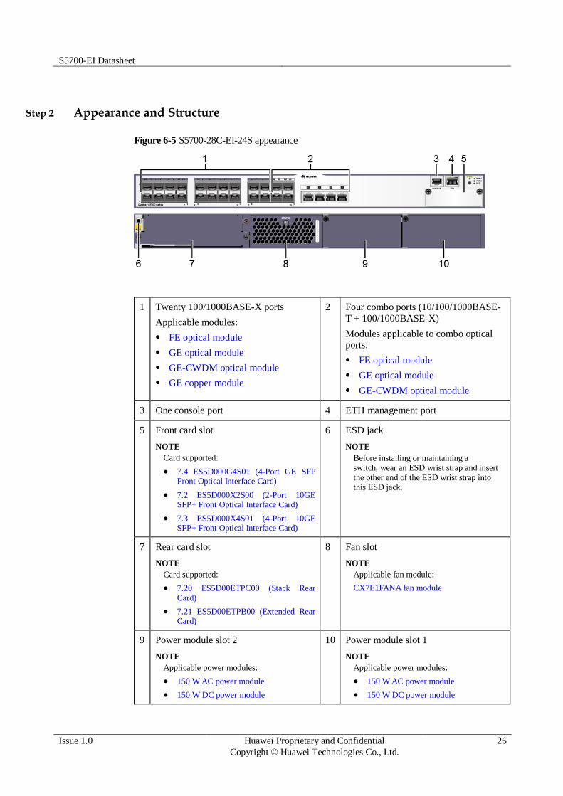
Step 2 Appearance and Structure
Figure 6-5 S5700-28C-EI-24S appearance
1 Twenty 100/1000BASE-X ports
Applicable modules:
FE optical module
GE optical module
GE-CWDM optical module
GE copper module
2 Four combo ports (10/100/1000BASE-
T + 100/1000BASE-X)
Modules applicable to combo optical ports:
FE optical module
GE optical module
GE-CWDM optical module
3 One console port 4 ETH management port
5 Front card slot
NOTE
Card supported:
7.4 ES5D000G4S01 (4-Port GE SFP Front Optical Interface Card)
7.2 ES5D000X2S00 (2-Port 10GE SFP+ Front Optical Interface Card)
7.3 ES5D000X4S01 (4-Port 10GE SFP+ Front Optical Interface Card)
6 ESD jack
NOTE
Before installing or maintaining a switch, wear an ESD wrist strap and insert the other end of the ESD wrist strap into this ESD jack.
7 Rear card slot
NOTE
Card supported:
7.20 ES5D00ETPC00 (Stack Rear Card)
7.21 ES5D00ETPB00 (Extended Rear Card)
8 Fan slot
NOTE
Applicable fan module:
CX7E1FANA fan module
9 Power module slot 2
NOTE
Applicable power modules:
150 W AC power module
150 W DC power module
10 Power module slot 1
NOTE
Applicable power modules:
150 W AC power module
150 W DC power module

S5700-EI Datasheet
Issue 1.0 Huawei Proprietary and Confidential
Copyright © Huawei Technologies Co., Ltd.
27
Step 3 Port Description
100/1000BASE-X port
A 100/1000BASE-X port can send and receive data at 100 Mbit/s or 1000 Mbit/s. Table 3-428
describes the attributes of a 100/1000BASE-X port.
Table 6-9 Attributes of a 100/1000BASE-X port
Attribute Description
Connector type LC/PC
Optical interface
attributes
Depend on the optical module used
Standards
compliance
IEEE802.3z
Working mode 100/1000 Mbit/s auto-sensing
Full-duplex
Combo port
A combo port refers to a pair of ports consisting of an optical Ethernet port and an electrical
Ethernet port on the panel. Each combo port matches only one internal forwarding port. A
combo port can be configured as an electrical port or an optical port, but only one port can be
active at a time. When one port is active, the other port is shut down.
By default, a combo port works in auto mode, in which the port type is determined as follows:
If the optical port has no optical module installed and the electrical port has no network cable connected, the port type depends on which port is connected first. If the electrical port is connected by a network cable first, the electrical port is used for data switching. If the optical port has an optical module installed first, the optical port is used for data switching.
If the electrical port has a network cable connected and is in Up state, the electrical port is still used for data switching when the optical port has an optical module installed.
If the optical port, no matter in Up or Down state, has an optical module installed, the optical port is still used for data switching when the electrical port has a network cable connected.
If the optical port has an optical module installed and the electrical port has a network cable connected, the optical port is used for data switching after the switch restarts.
You can configure a combo port as an electrical or optical port using the combo-port command.
Console port
The console port is connected to a console for on-site configuration. The port must use a
console cable. The console port is used when a switch is powered on for the first time. For
details about the attributes of a console port, see Table 3-429.
Table 6-10 Attributes of a console port
Attribute Description
Connector type RJ45
Standards RS-232

S5700-EI Datasheet
Issue 1.0 Huawei Proprietary and Confidential
Copyright © Huawei Technologies Co., Ltd.
28
Attribute Description
compliance
Working mode Duplex Universal Asynchronous Receiver/Transmitter (UART)
Baud rate 9600 bit/s, 19200 bit/s, 38400 bit/s, 57600 bit/s, or 115200 bit/s
Default value: 9600 bit/s
ETH management port
You can connect a switch to a configuration terminal or network management workstation
through the ETH management port to configure the switch locally or remotely. The port must
use a network cable. You can choose to download the software package through the ETH
management port in the BootROM menu. File transfer through the ETH management port is
faster than transfer through the console port. For details on how to use the ETH management
port, see the Configuration Guide - Basic Configurations. Table 3-430 describes the attributes
of an ETH management port.
Table 6-11 Attributes of an ETH management port
Attribute Description
Connector type RJ45
Standards
compliance
IEEE802.3
Working mode 10/100 Mbit/s auto-sensing
Full duplex
Maximum
transmission distance
100 m
Step 4 Indicator Description
The S5700-28C-EI-24S has the same types of indicators as the S5700-28C-EI. For details, see
Indicator Description.
Step 5 Power Supply Configuration
The S5700-28C-EI-24S can use a single power module or double power modules for 1+1
power redundancy. In versions prior to V200R005C00, the AC and DC power modules cannot
be configured on the same device, while in V200R005C00 and later versions, they can be
configured on the same device.
Figure 3-158 shows the power supply connections of dual DC power modules. After DC
power is transmitted to the PWR module, the PWR module provides 12 V output voltage, and
the motherboard provides power for the entire device.

S5700-EI Datasheet
Issue 1.0 Huawei Proprietary and Confidential
Copyright © Huawei Technologies Co., Ltd.
29
Figure 6-6 Power supply connections of dual DC power modules
PWR2
NEG RTN
Motherboard
GND12V
PWR1
NEG RTN
NEG: negative cable RTN: positive cable GND: 12 V reference ground
Figure 3-159 shows the power supply connections of dual non-PoE AC power modules. After
AC power is transmitted to the PWR module, the PWR module provides 12 V output voltage,
and the motherboard provides power for the entire device.
Figure 6-7 Power supply connections of dual non-PoE AC power modules
PWR2
L N
Motherboard
GND12V
PGND
PWR1
L N PGND
L:
Live wire
N:
Neutral wire
PGND: Protective
ground wire
GND: 12 V reference
ground
Step 6 Heat Dissipation
The S5700-28C-EI-24S uses pluggable fan modules for forced air cooling. Air flows in from
the left and right sides, and exhausts from the rear panel.

S5700-EI Datasheet
Issue 1.0 Huawei Proprietary and Confidential
Copyright © Huawei Technologies Co., Ltd.
30
This figure only shows the airflow direction and does not depict the actual device.
Step 7 Technical Specifications
Table 3-431 lists specifications of the S5700-28C-EI-24S.
Table 6-12 Technical specifications
Item Description
Memory (RAM) 256 MB
Flash 32 MB
Mean time between
failures (MTBF)
52.80 years when no interface card is configured, 41.33 years when a
2-port 10GE interface card is configured, 50.00 years when a 4-port
GE front card is configured, 26.52 years when a 4-port 10GE front card is configured
Mean time to repair
(MTTR)
2 hours
Availability > 0.99999
Service port surge
protection
±2 kV in common mode
Power supply surge
protection
Using AC power modules: ±6 kV in differential mode, ±6 kV in
common mode
Using DC power modules: ±1 kV in differential mode, ±2 kV in
common mode
Dimensions (W
x D x H)
442.0 mm x 420.0 mm x 43.6 mm (17.4 in. x 16.5 in. x 1.72 in.)
Weight Empty: ≤ 5 kg (11.02 lb)
Fully loaded: ≤ 8.5 kg (18.74 lb)
Stack ports Two stack ports available on each stack card
RPS Not supported
PoE Not supported
Rated voltage range 100 V AC to 240 V AC, 50/60 Hz
-48 V DC to -60 V DC
Maximum voltage
range
90 V AC to 264 V AC, 47 Hz to 63 Hz
-36 V DC to -72 V DC
Maximum power
consumption
(100% throughput, full speed of fans)
63 W
Operating temperature
0°C to 50°C (32°F to 122°F)

S5700-EI Datasheet
Issue 1.0 Huawei Proprietary and Confidential
Copyright © Huawei Technologies Co., Ltd.
31
Item Description
Storage
temperature
-40°C to +70°C (-40°F to +158°F)
Noise under normal
temperature (27°C, sound power)
< 41 dBA
Relative humidity 5% to 95%, noncondensing
Operating altitude AC power modules configured: 0-5000 m (0-16404 ft.)
DC power modules configured: 0-2000 m (0-6562 ft.)
Certification EMC certification
Safety certification
Manufacturing certification
S5700-28C-PWR-EI
Step 8 Version Mapping
Table 3-432 lists the mapping between the S5700-28C-PWR-EI and software versions.
Table 6-13 Version mapping
Series Model Software Version
S5700-EI S5700-28C-PWR-EI V100R005C01 to V200R005C03
NOTE
This model does not match V200R003C02 or V200R003C10.
Step 9 Appearance and Structure
Figure 6-8 S5700-28C-PWR-EI appearance

S5700-EI Datasheet
Issue 1.0 Huawei Proprietary and Confidential
Copyright © Huawei Technologies Co., Ltd.
32
1 Twenty-four PoE+ 10/100/1000BASE-T ports
2 One console port
3 ETH management port 4 Front card slot
NOTE
Card supported:
7.4 ES5D000G4S01 (4-Port GE SFP Front Optical Interface Card)
7.2 ES5D000X2S00 (2-Port 10GE SFP+ Front Optical Interface Card)
7.3 ES5D000X4S01 (4-Port 10GE SFP+ Front Optical Interface Card)
5 ESD jack
NOTE
Before installing or maintaining a switch, wear an ESD wrist strap and insert the other end of the ESD wrist strap into this ESD jack.
6 Rear card slot
NOTE
Card supported:
7.20 ES5D00ETPC00 (Stack Rear Card)
7.21 ES5D00ETPB00 (Extended Rear Card)
7 Fan slot
NOTE
Applicable fan module:
CX7E1FANA fan module
8 Power module slot 2
NOTE
Applicable power modules:
250 W AC PoE power module
500 W AC PoE power module
9 Power module slot 1
NOTE
Applicable power modules:
250 W AC PoE power module
500 W AC PoE power module
- -
Step 10 Port Description
10/100/1000BASE-T port
A 10/100/1000BASE-T Ethernet electrical port sends and receives service data at
10/100/1000 Mbit/s, and must use network cables. Table 3-433 describes the attributes of a
10/100/1000BASE-T Ethernet electrical port.
Table 6-14 Attributes of a 10/100/1000BASE-T Ethernet electrical port
Attribute Description
Connector type RJ45
Standards
compliance
IEEE802.3, IEEE802.3u, IEEE802.3ab
Working mode 10/100/1000 Mbit/s auto-sensing
Full-duplex
Maximum
transmission
100 m

S5700-EI Datasheet
Issue 1.0 Huawei Proprietary and Confidential
Copyright © Huawei Technologies Co., Ltd.
33
Attribute Description
distance
Console port
The console port is connected to a console for on-site configuration. The port must use a
console cable. The console port is used when a switch is powered on for the first time. For
details about the attributes of a console port, see Table 3-434.
Table 6-15 Attributes of a console port
Attribute Description
Connector type RJ45
Standards
compliance
RS-232
Working mode Duplex Universal Asynchronous Receiver/Transmitter (UART)
Baud rate 9600 bit/s, 19200 bit/s, 38400 bit/s, 57600 bit/s, or 115200 bit/s
Default value: 9600 bit/s
ETH management port
You can connect a switch to a configuration terminal or network management workstation
through the ETH management port to configure the switch locally or remotely. The port must
use a network cable. You can choose to download the software package through the ETH
management port in the BootROM menu. File transfer through the ETH management port is
faster than transfer through the console port. For details on how to use the ETH management
port, see the Configuration Guide - Basic Configurations. Table 3-435 describes the attributes
of an ETH management port.
Table 6-16 Attributes of an ETH management port
Attribute Description
Connector type RJ45
Standards
compliance
IEEE802.3
Working mode 10/100 Mbit/s auto-sensing
Full duplex
Maximum
transmission distance
100 m

S5700-EI Datasheet
Issue 1.0 Huawei Proprietary and Confidential
Copyright © Huawei Technologies Co., Ltd.
34
Step 11 Indicator Description
Figure 6-9 Indicators on the S5700-28C-PWR-EI
Table 6-17 Description of indicators on the switch
Number
Indicator/Button
Color Description
1 PWR1: power
supply indicator
- Off: No power module is available in
power module slot 1, or the switch has
only one power module but the power module does not work normally.
Green Steady on: A power module is installed in
power module slot 1 and is working
normally.
Red Steady on: The switch has two power
modules installed. Any of the following situations occurs in power module slot 1:
A power module is available in this
slot but its power switch is in the OFF
position.
A power module is available in this
slot but it is not connected to a power source.
The system power and PoE power are faulty.
Yellow Steady on: If a single power module is
installed, the PoE power is out of range.
If dual power modules are installed, the
system power or PoE power is out of range.
2 PWR2: power - Off: No power module is available in
power module slot 2, or the switch has

S5700-EI Datasheet
Issue 1.0 Huawei Proprietary and Confidential
Copyright © Huawei Technologies Co., Ltd.
35
Number
Indicator/Button
Color Description
supply indicator only one power module but the power
module does not work normally.
Green Steady on: A power module is installed in
power module slot 2 and is working normally.
Red Steady on: The switch has two power
modules installed. Any of the following
situations occurs in power module slot 2:
A power module is available in this
slot but its power switch is in the OFF position.
A power module is available in this
slot but it is not connected to a power
source.
The system power and PoE power are faulty.
Yellow Steady on: If a single power module is
installed, the PoE power is out of range.
If dual power modules are installed, the
system power or PoE power is out of range.
3 SYS: system
status indicator
- Off: The system is not running.
Green Steady on: The system is not
operating properly or is starting.
Slow blinking: The system is running normally.
Yellow Steady on: The system is performing self-
check during startup.
Red Steady on: The system does not work
normally after registration, or a fan or
temperature alarm has been generated.
4 Mode indicator - Off: The service port indicators are in the
status mode (default). In the status mode,
the service port indicator shows the port link or activity state.
Green Steady on: The service port indicators
show the port speed. After 45 seconds,
the service port indicators automatically restore to the status mode.
Red Steady on: The service port indicators
show the stack ID of the switch. After 45
seconds, the service port indicators
automatically restore to the status mode.

S5700-EI Datasheet
Issue 1.0 Huawei Proprietary and Confidential
Copyright © Huawei Technologies Co., Ltd.
36
Number
Indicator/Button
Color Description
Yellow Steady on: The service port indicators
show the PoE status. After 45 seconds,
the service port indicators automatically restore to the status mode.
5 Mode switch
button
- When you press this button once, the
mode indicator turns green and the
service port indicators show the speed
of each service port.
When you press this button a second
time, the mode indicator turns red and
the service port indicators show the
stack status.
When you press this button a third
time, the mode indicator turns yellow
and the service port indicators show
the PoE status.
When you press this button a fourth time, the mode indicator turns off.
If you do not press the button within 45
seconds, the mode indicator restores to status mode.
6 Service port indicator
Meanings of service port indicators vary in different modes. For details, see Table 3-437.
7 ETH indicator - Off: No link is established on the port.
Green Steady on: The port is connected.
Yellow Blinking: The port is sending or receiving
data.
Table 6-18 Description of service port indicators in different modes
Display Mode Color Description
Status Green Off: The port is not connected or has
been shut down.
Steady on: The port is connected.
Blinking: The port is sending or receiving data.
Speed Green Off: The port is not connected or has
been shut down.
Steady on:
10M/100M/1000M port: The port is operating at 10/100 Mbit/s.
1000M/10GE port: The port is

S5700-EI Datasheet
Issue 1.0 Huawei Proprietary and Confidential
Copyright © Huawei Technologies Co., Ltd.
37
Display Mode Color Description
operating at 1000 Mbit/s.
Blinking:
10M/100M/1000M port: The port is operating at 1000 Mbit/s.
1000M/10GE port: The port is operating at 10 Gbit/s.
PoE Green Off: The port does not provide PoE
power.
Steady on: The port is providing PoE
power.
Blinking: The PD connected to the
port is not a standard PD or its power
exceeds the maximum power or
power threshold of the port.
Stack Green Off: The STCK mode is not selected.
If the indicator is steady on, the
switch is not a master switch:
If the indicator of a port is steady
on, the number of this port is the stack ID of the switch.
If the first nine port indicators of
the switch are steady on, the stack
ID of the switch is 0.
If the indicator is blinking, the switch is a master switch:
If the indicator of a port is
blinking, the number of this port is
the stack ID of the switch.
If the first nine port indicators of
the switch are blinking, the stack ID of the switch is 0.
Step 12 Power Supply Configuration
The S5700-28C-PWR-EI is a PoE switch. It has two power module slots, each of which can
have a 500 W or 250 W power module installed. A power module can provide 369.6 W or
123.2 W of PoE power for powered devices (PDs). Table 3-438 lists its power supply
configurations.
Table 6-19 Power supply configurations
Power Module 1
Power Module 2
Available PoE Power
Maximum Number of Ports (Fully Loaded)
250 W – 123.2 W 802.3af (15.4 W per port): 8

S5700-EI Datasheet
Issue 1.0 Huawei Proprietary and Confidential
Copyright © Huawei Technologies Co., Ltd.
38
Power Module 1
Power Module 2
Available PoE Power
Maximum Number of Ports (Fully Loaded)
802.3at (30 W per port): 4
500 W – 369.6 W 802.3af (15.4 W per port):
24
802.3at (30 W per port):
12
250 W 250 W 246.4 W 802.3af (15.4 W per port):
16
802.3at (30 W per port): 8
500 W 500 W 369.6 W (with PCB of
version A for the S5700-28C-PWR-EI)
802.3af (15.4 W per port):
24
802.3at (30 W per port): 12
739.2 W (with PCB of
version B for the
S5700-28C-PWR-EI)
802.3af (15.4 W per port):
24
802.3at (30 W per port):
24
Figure 3-162 shows the power supply mode of dual AC PoE power modules (PWR1 and
PWR2). After AC power is transmitted to the PWR modules, the PWR modules provide 12 V
and -53 V outputs. The outputs are combined on the motherboard, which then provides 12 V
voltage for the switch and -53 V voltage for the PDs.
Figure 6-10 Power supply by dual AC PoE power modules
PWR2
L N
Motherboard
GND12V
PGND
PWR1
L N PGND
-53V RTN
L:
live wire
N:
neutral wire
PGND: protection
ground
GND: 12 V
reference ground
RTN: -53 V
reference ground
Step 13 Heat Dissipation
The S5700-28C-PWR-EI uses pluggable fan modules for forced air cooling. Air flows in from
the left and right sides, and exhausts from the rear panel.

S5700-EI Datasheet
Issue 1.0 Huawei Proprietary and Confidential
Copyright © Huawei Technologies Co., Ltd.
39
Step 14 Technical Specifications
Table 3-439 lists specifications of the S5700-28C-PWR-EI.
Table 6-20 Technical specifications
Item Description
Memory (RAM) 256 MB
Flash 32 MB
Mean time between
failures (MTBF)
52 years when a 2-port 10GE interface card is configured, 55.4
years when a 4-port GE front card is configured, 32.92 years when a 4-port 10GE front card is configured
Mean time to repair
(MTTR)
2 hours
Availability > 0.99999
Service port surge
protection
±1 kV in common mode
Power supply surge
protection
±2 kV in differential mode, ±4 kV in common mode
Dimensions (W
x D x H)
442.0 mm x 420.0 mm x 43.6 mm (17.4 in. x 16.5 in. x 1.72 in.)
Weight Empty: ≤ 5 kg (11.02 lb)
Fully loaded: ≤ 8.5 kg (18.74 lb)
Stack ports Two stack ports available on each stack card
RPS Not supported
PoE Supported
Rated voltage range 100 V AC to 240 V AC, 50/60 Hz
Maximum voltage
range
90 V AC to 264 V AC, 47 Hz to 63 Hz
Maximum power
consumption
842 W (system power consumption: 102 W, PoE: 740 W)

S5700-EI Datasheet
Issue 1.0 Huawei Proprietary and Confidential
Copyright © Huawei Technologies Co., Ltd.
40
Item Description
(100% throughput,
100% PoE loads, full speed of fans)
Operating
temperature
0°C to 50°C (32°F to 122°F)
Storage
temperature
-40°C to +70°C (-40°F to +158°F)
Noise under normal
temperature (27°C, sound power)
< 45 dBA
Relative humidity 5% to 95%, noncondensing
Operating altitude 0-5000 m (0-16404 ft.)
Certification EMC certification
Safety certification
Manufacturing certification
6.1.3 S5700-52C-EI
Step 1 Version Mapping
Table 3-440 lists the mapping between the S5700-52C-EI and software versions.
Table 6-21 Version mapping
Series Model Software Version
S5700-EI S5700-52C-EI V100R005C01 to V200R005C03
NOTE
This model does not match V200R003C02 or V200R003C10.

S5700-EI Datasheet
Issue 1.0 Huawei Proprietary and Confidential
Copyright © Huawei Technologies Co., Ltd.
41
Step 2 Appearance and Structure
Figure 6-11 S5700-52C-EI appearance
1 Forty-eight 10/100/1000BASE-T ports 2 One console port
3 ETH management port 4 Front card slot
NOTE
Card supported:
7.4 ES5D000G4S01 (4-Port GE SFP Front Optical Interface Card)
7.2 ES5D000X2S00 (2-Port 10GE SFP+ Front Optical Interface Card)
7.3 ES5D000X4S01 (4-Port 10GE SFP+ Front Optical Interface Card)
5 ESD jack
NOTE
Before installing or maintaining a switch, wear an ESD wrist strap and insert the other end of the ESD wrist strap into this ESD jack.
6 Rear card slot
NOTE
Card supported:
7.20 ES5D00ETPC00 (Stack Rear Card)
7.21 ES5D00ETPB00 (Extended Rear Card)
7 Fan slot
NOTE
Applicable fan module:
CX7E1FANA fan module
8 Power module slot 2
NOTE
Applicable power modules:
150 W AC power module
150 W DC power module
9 Power module slot 1
NOTE
Applicable power modules:
150 W AC power module
150 W DC power module
- -
Step 3 Port Description
10/100/1000BASE-T port

S5700-EI Datasheet
Issue 1.0 Huawei Proprietary and Confidential
Copyright © Huawei Technologies Co., Ltd.
42
A 10/100/1000BASE-T Ethernet electrical port sends and receives service data at
10/100/1000 Mbit/s, and must use network cables. Table 3-441 describes the attributes of a
10/100/1000BASE-T Ethernet electrical port.
Table 6-22 Attributes of a 10/100/1000BASE-T Ethernet electrical port
Attribute Description
Connector type RJ45
Standards
compliance
IEEE802.3, IEEE802.3u, IEEE802.3ab
Working mode 10/100/1000 Mbit/s auto-sensing
Full-duplex
Maximum
transmission distance
100 m
Console port
The console port is connected to a console for on-site configuration. The port must use a
console cable. The console port is used when a switch is powered on for the first time. For
details about the attributes of a console port, see Table 3-442.
Table 6-23 Attributes of a console port
Attribute Description
Connector type RJ45
Standards compliance
RS-232
Working mode Duplex Universal Asynchronous Receiver/Transmitter (UART)
Baud rate 9600 bit/s, 19200 bit/s, 38400 bit/s, 57600 bit/s, or 115200 bit/s
Default value: 9600 bit/s
ETH management port
You can connect a switch to a configuration terminal or network management workstation
through the ETH management port to configure the switch locally or remotely. The port must
use a network cable. You can choose to download the software package through the ETH
management port in the BootROM menu. File transfer through the ETH management port is
faster than transfer through the console port. For details on how to use the ETH management
port, see the Configuration Guide - Basic Configurations. Table 3-443 describes the attributes
of an ETH management port.

S5700-EI Datasheet
Issue 1.0 Huawei Proprietary and Confidential
Copyright © Huawei Technologies Co., Ltd.
43
Table 6-24 Attributes of an ETH management port
Attribute Description
Connector type RJ45
Standards
compliance
IEEE802.3
Working mode 10/100 Mbit/s auto-sensing
Full duplex
Maximum
transmission
distance
100 m
Step 4 Indicator Description
The S5700-52C-EI has the same types of indicators as the S5700-28C-EI. For details, see
Indicator Description.
Step 5 Power Supply Configuration
The S5700-52C-EI can use a single power module or double power modules for 1+1 power
redundancy. In versions prior to V200R005C00, the switch cannot use pluggable AC and DC
power modules simultaneously. In V200R005C00 and later versions, the switch supports
mixing of pluggable AC and DC power modules.
Figure 3-164 shows the power supply connections of dual DC power modules. After DC
power is transmitted to the PWR module, the PWR module provides 12 V output voltage, and
the motherboard provides power for the entire device.
Figure 6-12 Power supply connections of dual DC power modules
PWR2
NEG RTN
Motherboard
GND12V
PWR1
NEG RTN
NEG: negative cable RTN: positive cable GND: 12 V reference ground
Figure 3-165 shows the power supply connections of dual non-PoE AC power modules. After
AC power is transmitted to the PWR module, the PWR module provides 12 V output voltage,
and the motherboard provides power for the entire device.

S5700-EI Datasheet
Issue 1.0 Huawei Proprietary and Confidential
Copyright © Huawei Technologies Co., Ltd.
44
Figure 6-13 Power supply connections of dual non-PoE AC power modules
PWR2
L N
Motherboard
GND12V
PGND
PWR1
L N PGND
L:
Live wire
N:
Neutral wire
PGND: Protective
ground wire
GND: 12 V reference
ground
Step 6 Heat Dissipation
The S5700-52C-EI uses pluggable fan modules for forced air cooling. Air flows in from the
left and right sides, and exhausts from the rear panel.
This figure only shows the airflow direction and does not depict the actual device.
Step 7 Technical Specifications
Table 3-444 lists specifications of the S5700-52C-EI.
Table 6-25 Technical specifications
Item Description
Memory (RAM) 256 MB
Flash 32 MB
Mean time between
failures (MTBF)
46.05 years when a 2-port 10GE interface card is configured, 57.08
years when a 4-port GE front card is configured, 25.58 years when a 4x10GE front card is configured
Mean time to repair (MTTR)
2 years

S5700-EI Datasheet
Issue 1.0 Huawei Proprietary and Confidential
Copyright © Huawei Technologies Co., Ltd.
45
Item Description
Availability > 0.99999
Service port surge
protection
Common mode: ±2 kV
Power supply surge
protection
Using AC power modules: ±6 kV in differential mode, ±6 kV in
common mode
Using DC power modules: ±1 kV in differential mode, ±2 kV in
common mode
Dimensions (W
x D x H)
442.0 mm x 420.0 mm x 43.6 mm (17.4 in. x 16.5 in. x 1.72 in.)
Weight Empty: ≤ 5 kg (11.02 lb)
Fully loaded: ≤ 8.5 kg (18.74 lb)
Stack ports Two stack ports available on each stack card
RPS Not supported
PoE Not supported
Rated voltage range 100 V AC to 240 V AC, 50/60 Hz
-48 V DC to -60 V DC
Maximum voltage
range
90 V AC to 264 V AC, 47 Hz to 63 Hz
-36 V DC to -72 V DC
Maximum power
consumption
(100% throughput, full speed of fans)
88 W
Operating
temperature
0°C to 50°C (32°F to 122°F)
Storage
temperature
-40°C to +70°C (-40°F to +158°F)
Noise under normal
temperature (27°C,
sound power)
< 41 dBA
Relative humidity 5% to 95%, noncondensing
Operating altitude AC power modules configured: 0-5000 m (0-16404 ft.)
DC power modules configured: 0-2000 m (0-6562 ft.)
Certification EMC certification
Safety certification
Manufacturing certification

S5700-EI Datasheet
Issue 1.0 Huawei Proprietary and Confidential
Copyright © Huawei Technologies Co., Ltd.
46
6.1.4 S5700-52C-PWR-EI
Step 1 Version Mapping
Table 3-445 lists the mapping between the S5700-52C-PWR-EI and software versions.
Table 6-26 Version mapping
Series Model Software Version
S5700-EI S5700-52C-PWR-EI V100R005C01 to V200R005C03
NOTE
This model does not match V200R003C02 or V200R003C10.
Step 2 Appearance and Structure
Figure 6-14 S5700-52C-PWR-EI appearance
1 Forty-eight PoE+ 10/100/1000BASE-T
ports
2 One console port
3 ETH management port 4 Front card slot
NOTE
Card supported:
7.4 ES5D000G4S01 (4-Port GE SFP Front Optical Interface Card)
7.2 ES5D000X2S00 (2-Port 10GE SFP+ Front Optical Interface Card)
7.3 ES5D000X4S01 (4-Port 10GE SFP+ Front Optical Interface Card)
5 ESD jack
NOTE
Before installing or maintaining a switch, wear an ESD wrist strap and insert the other end of the ESD wrist strap into this ESD jack.
6 Rear card slot
NOTE
Card supported:
7.20 ES5D00ETPC00 (Stack Rear Card)
7.21 ES5D00ETPB00 (Extended Rear Card)
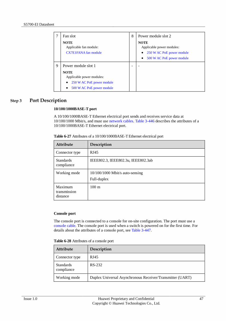
S5700-EI Datasheet
Issue 1.0 Huawei Proprietary and Confidential
Copyright © Huawei Technologies Co., Ltd.
47
7 Fan slot
NOTE
Applicable fan module:
CX7E1FANA fan module
8 Power module slot 2
NOTE
Applicable power modules:
250 W AC PoE power module
500 W AC PoE power module
9 Power module slot 1
NOTE
Applicable power modules:
250 W AC PoE power module
500 W AC PoE power module
- -
Step 3 Port Description
10/100/1000BASE-T port
A 10/100/1000BASE-T Ethernet electrical port sends and receives service data at
10/100/1000 Mbit/s, and must use network cables. Table 3-446 describes the attributes of a
10/100/1000BASE-T Ethernet electrical port.
Table 6-27 Attributes of a 10/100/1000BASE-T Ethernet electrical port
Attribute Description
Connector type RJ45
Standards
compliance
IEEE802.3, IEEE802.3u, IEEE802.3ab
Working mode 10/100/1000 Mbit/s auto-sensing
Full-duplex
Maximum
transmission distance
100 m
Console port
The console port is connected to a console for on-site configuration. The port must use a
console cable. The console port is used when a switch is powered on for the first time. For
details about the attributes of a console port, see Table 3-447.
Table 6-28 Attributes of a console port
Attribute Description
Connector type RJ45
Standards
compliance
RS-232
Working mode Duplex Universal Asynchronous Receiver/Transmitter (UART)

S5700-EI Datasheet
Issue 1.0 Huawei Proprietary and Confidential
Copyright © Huawei Technologies Co., Ltd.
48
Attribute Description
Baud rate 9600 bit/s, 19200 bit/s, 38400 bit/s, 57600 bit/s, or 115200 bit/s
Default value: 9600 bit/s
ETH management port
You can connect a switch to a configuration terminal or network management workstation
through the ETH management port to configure the switch locally or remotely. The port must
use a network cable. You can choose to download the software package through the ETH
management port in the BootROM menu. File transfer through the ETH management port is
faster than transfer through the console port. For details on how to use the ETH management
port, see the Configuration Guide - Basic Configurations. Table 3-448 describes the attributes
of an ETH management port.
Table 6-29 Attributes of an ETH management port
Attribute Description
Connector type RJ45
Standards
compliance
IEEE802.3
Working mode 10/100 Mbit/s auto-sensing
Full duplex
Maximum
transmission distance
100 m
Step 4 Indicator Description
The S5700-52C-PWR-EI has the same types of indicators as the S5700-28C-PWR-EI. For
details, see Indicator Description.
Step 5 Power Supply Configuration
The S5700-52C-PWR-EI is a PoE switch. It has two power module slots, each of which can
have a 500 W or 250 W power module installed. A power module can provide 369.6 W or
123.2 W of PoE power for powered devices (PDs). Table 3-449 lists its power supply
configurations.
Table 6-30 Power supply configurations
Power Module 1
Power Module 2
Available PoE Power
Maximum Number of Ports (Fully Loaded)
250 W – 123.2 W 802.3af (15.4 W per port):
8
802.3at (30 W per port): 4

S5700-EI Datasheet
Issue 1.0 Huawei Proprietary and Confidential
Copyright © Huawei Technologies Co., Ltd.
49
Power Module 1
Power Module 2
Available PoE Power
Maximum Number of Ports (Fully Loaded)
500 W – 369.6 W 802.3af (15.4 W per port):
24
802.3at (30 W per port):
12
250 W 250 W 246.4 W 802.3af (15.4 W per port):
16
802.3at (30 W per port): 8
500 W 500 W 739.2 W 802.3af (15.4 W per port):
48
802.3at (30 W per port): 24
When a switch has two power modules installed, the two power modules work in redundancy mode to provide power for the chassis and in load balancing mode to provide power for PDs.
Figure 3-167 shows the power supply mode of dual AC PoE power modules (PWR1 and
PWR2). After AC power is transmitted to the PWR modules, the PWR modules provide 12 V
and -53 V outputs. The outputs are combined on the motherboard, which then provides 12 V
voltage for the switch and -53 V voltage for the PDs.
Figure 6-15 Power supply by dual AC PoE power modules
PWR2
L N
Motherboard
GND12V
PGND
PWR1
L N PGND
-53V RTN
L:
live wire
N:
neutral wire
PGND: protection
ground
GND: 12 V
reference ground
RTN: -53 V
reference ground
Step 6 Heat Dissipation
The S5700-52C-PWR-EI uses pluggable fan modules for forced air cooling. Air flows in from
the left and right sides, and exhausts from the rear panel.

S5700-EI Datasheet
Issue 1.0 Huawei Proprietary and Confidential
Copyright © Huawei Technologies Co., Ltd.
50
This figure only shows the airflow direction and does not depict the actual device.
Step 7 Technical Specifications
Table 3-450 lists specifications of the S5700-52C-PWR-EI.
Table 6-31 Technical specifications
Item Description
Memory (RAM) 256 MB
Flash 32 MB
Mean time between
failures (MTBF)
44.8 years when a 2-port 10GE interface card is configured, 66.8
years when a 4-port GE front card is configured, 29.89 years when a 4x10GE front card is configured
Mean time to repair
(MTTR)
2 hours
Availability > 0.99999
Service port surge
protection
Common mode: ±1 kV
Power supply surge
protection
±2 kV in differential mode, ±4 kV in common mode
Dimensions (W
x D x H)
442.0 mm x 420.0 mm x 43.6 mm (17.4 in. x 16.5 in. x 1.72 in.)
Weight Empty: ≤ 5 kg (11.02 lb)
Fully loaded: ≤ 8.5 kg (18.74 lb)
Stack ports Two stack ports available on each stack card
RPS Not supported
PoE Supported
Rated voltage range 100 V AC to 240 V AC, 50/60 Hz
Maximum voltage range
90 V AC to 264 V AC, 47 Hz to 63 Hz

S5700-EI Datasheet
Issue 1.0 Huawei Proprietary and Confidential
Copyright © Huawei Technologies Co., Ltd.
51
Item Description
Maximum power
consumption
(100% throughput,
100% PoE loads,
full speed of fans)
930 W (system power consumption: 190 W, PoE: 740 W)
Operating
temperature
0°C to 50°C (32°F to 122°F)
Storage
temperature
-40°C to +70°C (-40°F to +158°F)
Noise under normal
temperature (27°C, sound power)
< 45 dBA
Relative humidity 5% to 95%, noncondensing
Operating altitude 0-5000 m (0-16404 ft.)
Certification EMC certification
Safety certification
Manufacturing certification
6.2 S5710-EI
6.2.1 S5710-28C-EI
Step 1 Version Mapping
Table 3-451 lists the mapping between the S5710-28C-EI chassis and software versions.
Table 6-32 Version mapping
Series Model Software Version
S5710-EI S5710-28C-EI V200R001C00 to V200R005C02
NOTE
This model does not match V200R001C01, V200R003C02, V200R003C10, or V200R005C01.

S5700-EI Datasheet
Issue 1.0 Huawei Proprietary and Confidential
Copyright © Huawei Technologies Co., Ltd.
52
Step 2 Appearance and Structure
Figure 6-16 S5710-28C-EI appearance
1 Twenty 10/100/1000BASE-T ports 2 Four combo ports (10/100/1000BASE-
T + 100/1000BASE-X)
Modules applicable to the combo optical ports:
FE optical module
GE optical module
GE-CWDM optical module
GE-DWDM optical module
3 Four 10GE SFP+ ports
Applicable modules and cables:
GE optical module
GE-CWDM optical module
GE-DWDM optical module
GE copper module
10GE SFP+ optical module
10GE-CWDM optical module (applicable in V200R005C00)
1 m, 3 m, and 10 m SFP+ high-speed copper cables
3 m and 10 m AOC cables
(applicable in V200R003C00 and later versions)
4 ETH management port
5 One mini USB port 6 One console port
7 One USB port 8 Ground screw
NOTE
It is used with a ground cable.
9 Rear card slot 1
NOTE
Card supported:
10 Rear card slot 2
NOTE
Card supported:

S5700-EI Datasheet
Issue 1.0 Huawei Proprietary and Confidential
Copyright © Huawei Technologies Co., Ltd.
53
7.9 ES5D21G08S00 (8-Port GE SFP Rear Optical Interface Card)
7.10 ES5D21G08T00 (8-Port GE Rear Electrical Interface Card)
7.11 ES5D21X02S00 (2-Port GE SFP/10GE SFP+ Rear Optical Interface Card)
7.9 ES5D21G08S00 (8-Port GE SFP Rear Optical Interface Card)
7.10 ES5D21G08T00 (8-Port GE Rear Electrical Interface Card)
7.11 ES5D21X02S00 (2-Port GE SFP/10GE SFP+ Rear Optical Interface Card)
11 ESN label
NOTE
You can draw it out to view the ESN and MAC address of the switch.
12 Power module slot 2
NOTE
Applicable power modules:
150 W AC power module
150 W DC power module
13 Power module slot 1
NOTE
Applicable power modules:
150 W AC power module
150 W DC power module
- -
Step 3 Port Description
10/100/1000BASE-T port
A 10/100/1000BASE-T Ethernet electrical port sends and receives service data at
10/100/1000 Mbit/s, and must use network cables. Table 3-452 describes the attributes of a
10/100/1000BASE-T Ethernet electrical port.
Table 6-33 Attributes of a 10/100/1000BASE-T Ethernet electrical port
Attribute Description
Connector type RJ45
Standards
compliance
IEEE802.3, IEEE802.3u, IEEE802.3ab
Working mode 10/100/1000 Mbit/s auto-sensing
Full-duplex
Maximum
transmission distance
100 m
Combo port
A combo port refers to a pair of ports consisting of an optical Ethernet port and an electrical
Ethernet port on the panel. Each combo port matches only one internal forwarding port. A
combo port can be configured as an electrical port or an optical port, but only one port can be
active at a time. When one port is active, the other port is shut down.
By default, a combo port works in auto mode, in which the port type is determined as follows:
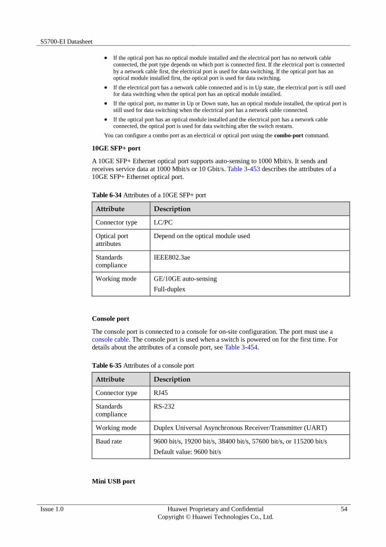
S5700-EI Datasheet
Issue 1.0 Huawei Proprietary and Confidential
Copyright © Huawei Technologies Co., Ltd.
54
If the optical port has no optical module installed and the electrical port has no network cable connected, the port type depends on which port is connected first. If the electrical port is connected
by a network cable first, the electrical port is used for data switching. If the optical port has an optical module installed first, the optical port is used for data switching.
If the electrical port has a network cable connected and is in Up state, the electrical port is still used for data switching when the optical port has an optical module installed.
If the optical port, no matter in Up or Down state, has an optical module installed, the optical port is still used for data switching when the electrical port has a network cable connected.
If the optical port has an optical module installed and the electrical port has a network cable connected, the optical port is used for data switching after the switch restarts.
You can configure a combo port as an electrical or optical port using the combo-port command.
10GE SFP+ port
A 10GE SFP+ Ethernet optical port supports auto-sensing to 1000 Mbit/s. It sends and
receives service data at 1000 Mbit/s or 10 Gbit/s. Table 3-453 describes the attributes of a
10GE SFP+ Ethernet optical port.
Table 6-34 Attributes of a 10GE SFP+ port
Attribute Description
Connector type LC/PC
Optical port
attributes
Depend on the optical module used
Standards
compliance
IEEE802.3ae
Working mode GE/10GE auto-sensing
Full-duplex
Console port
The console port is connected to a console for on-site configuration. The port must use a
console cable. The console port is used when a switch is powered on for the first time. For
details about the attributes of a console port, see Table 3-454.
Table 6-35 Attributes of a console port
Attribute Description
Connector type RJ45
Standards
compliance
RS-232
Working mode Duplex Universal Asynchronous Receiver/Transmitter (UART)
Baud rate 9600 bit/s, 19200 bit/s, 38400 bit/s, 57600 bit/s, or 115200 bit/s
Default value: 9600 bit/s
Mini USB port

S5700-EI Datasheet
Issue 1.0 Huawei Proprietary and Confidential
Copyright © Huawei Technologies Co., Ltd.
55
The mini USB port is connected to a console for on-site configuration. When both the Mini
USB and console port have a cable connected, only the Mini USB port works.
ETH management port
You can connect a switch to a configuration terminal or network management workstation
through the ETH management port to configure the switch locally or remotely. The port must
use a network cable. You can choose to download the software package through the ETH
management port in the BootROM menu. File transfer through the ETH management port is
faster than transfer through the console port. For details on how to use the ETH management
port, see the Configuration Guide - Basic Configurations. Table 3-455 describes the attributes
of an ETH management port.
Table 6-36 Attributes of an ETH management port
Attribute Description
Connector type RJ45
Standards
compliance
IEEE802.3
Working mode 10/100 Mbit/s auto-sensing
Full duplex
Maximum
transmission distance
100 m
USB port
The USB port can have a USB flash drive connected to upgrade the switch, or transfer
configuration files or other files. The USB flash drive used on a switch must comply with
USB 1.1 and support the Linux operating system. Table 3-456 lists the USB flash drives
applicable to a switch.
Table 6-37 USB flash drives applicable to a switch
Capacity
Vendor Model Remarks
4 GB Netac U208 You can buy Netac USB 4 GB flash drives
from Huawei or other vendors.
SanDisk Cruzer Blade Huawei does not offer this USB flash drive,
and you must buy it from other vendors.
Hewlett-
Packard
v218G Huawei does not offer this USB flash drive,
and you must buy it from other vendors.
PNY M1 Huawei does not offer this USB flash drive,
and you must buy it from other vendors.
8 GB Netac U208 Huawei does not offer this USB flash drive,
and you must buy it from other vendors.

S5700-EI Datasheet
Issue 1.0 Huawei Proprietary and Confidential
Copyright © Huawei Technologies Co., Ltd.
56
Capacity
Vendor Model Remarks
Hewlett-
Packard
v225w Huawei does not offer this USB flash drive,
and you must buy it from other vendors.
STEC SLUFD8GU2TUI
Huawei does not offer this USB flash drive, and you must buy it from other vendors.
Huawei is not responsible for maintenance service of USB flash drives purchased from other vendors.
Step 4 Indicator Description
Figure 6-17 Indicators on the S5710-28C-EI
Table 6-38 Description of indicators on the switch
Number Indicator Color Description
1 PWR1: power
supply indicator
- Off: No power module is available in
power module slot 1, or the switch has
only one power module but the power module does not work normally.
Green Steady on: A power module is installed in
power module slot 1 and is working
normally.
Yellow Steady on: The switch has two power
modules installed. Any of the following situations occurs in power module slot 1:
A power module is available in this
slot but its power switch is in the OFF
position.

S5700-EI Datasheet
Issue 1.0 Huawei Proprietary and Confidential
Copyright © Huawei Technologies Co., Ltd.
57
Number Indicator Color Description
A power module is available in this
slot but it is not connected to a power source.
The power module in power module
slot 1 fails.
2 PWR2: power
supply indicator
- Off: No power module is available in
power module slot 2, or the switch has
only one power module but the power module does not work normally.
Green Steady on: A power module is installed in
power module slot 2 and is working
normally.
Yellow Steady on: The switch has two power
modules installed. Any of the following situations occurs in power module slot 2:
A power module is available in this
slot but its power switch is in the OFF
position.
A power module is available in this
slot but it is not connected to a power source.
The power module in power module
slot 2 fails.
3 SYS: system
status indicator
- Off: The system is not running.
Green Fast blinking: The system is starting
or is copying the system software and
configuration file from a USB flash drive.
Slow blinking: The system is running properly.
Yellow Blinking: The system has been
successfully upgraded using a USB flash
drive and the switch has restarted. You
can remove the USB flash drive from the switch.
Red Steady on: The system does not work
normally after registration, or a fan or
temperature alarm has been generated.
Blinking: An error occurred during
USB-based upgrade and the system
failed to be upgraded after a USB
flash drive is inserted.
4 STAT: status
indicator
Green Off: The status mode is not selected.
Steady on: The status mode (default
mode) is selected. If the status mode
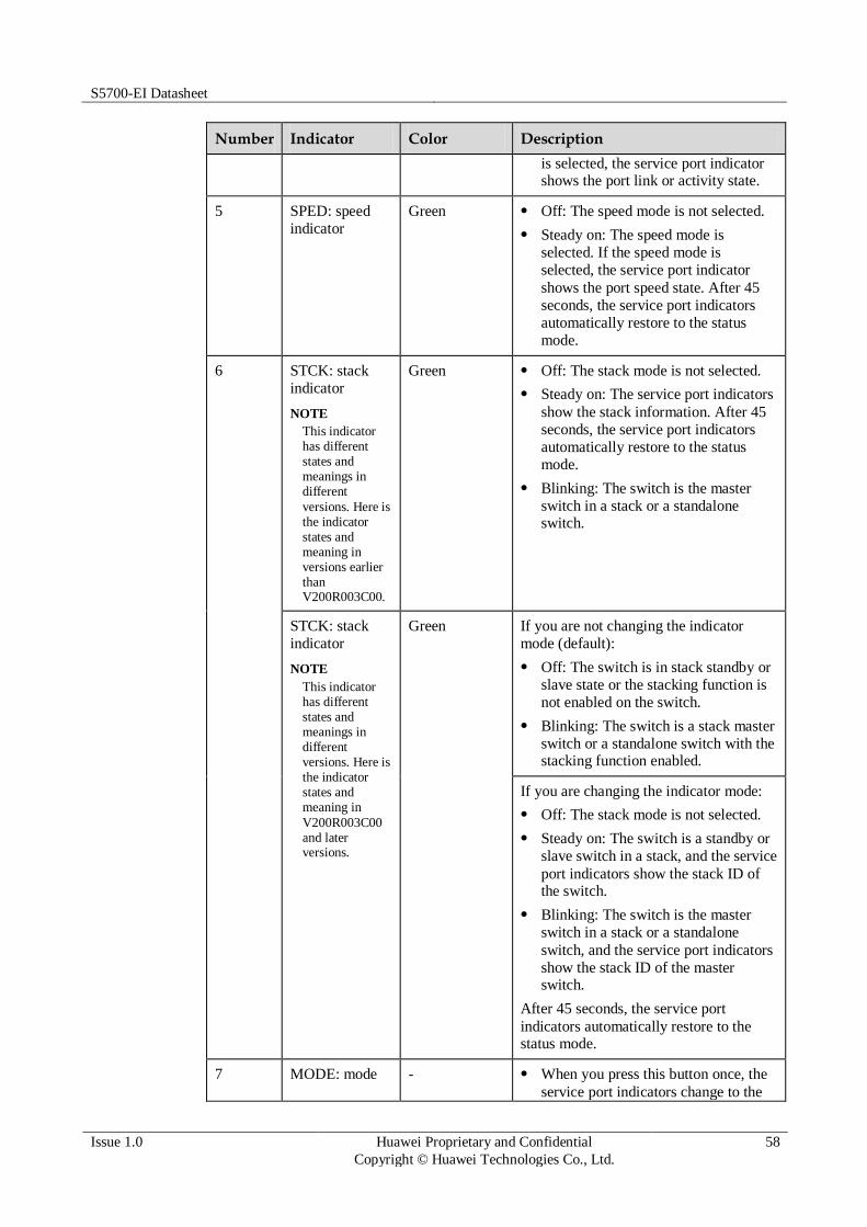
S5700-EI Datasheet
Issue 1.0 Huawei Proprietary and Confidential
Copyright © Huawei Technologies Co., Ltd.
58
Number Indicator Color Description
is selected, the service port indicator shows the port link or activity state.
5 SPED: speed
indicator
Green Off: The speed mode is not selected.
Steady on: The speed mode is
selected. If the speed mode is
selected, the service port indicator
shows the port speed state. After 45
seconds, the service port indicators
automatically restore to the status
mode.
6 STCK: stack
indicator
NOTE
This indicator has different states and meanings in different
versions. Here is the indicator states and meaning in versions earlier than V200R003C00.
Green Off: The stack mode is not selected.
Steady on: The service port indicators
show the stack information. After 45
seconds, the service port indicators
automatically restore to the status
mode.
Blinking: The switch is the master
switch in a stack or a standalone switch.
STCK: stack
indicator
NOTE
This indicator has different states and meanings in different versions. Here is the indicator states and meaning in
V200R003C00 and later versions.
Green If you are not changing the indicator
mode (default):
Off: The switch is in stack standby or
slave state or the stacking function is
not enabled on the switch.
Blinking: The switch is a stack master
switch or a standalone switch with the stacking function enabled.
If you are changing the indicator mode:
Off: The stack mode is not selected.
Steady on: The switch is a standby or
slave switch in a stack, and the service
port indicators show the stack ID of the switch.
Blinking: The switch is the master
switch in a stack or a standalone
switch, and the service port indicators
show the stack ID of the master switch.
After 45 seconds, the service port
indicators automatically restore to the status mode.
7 MODE: mode - When you press this button once, the
service port indicators change to the

S5700-EI Datasheet
Issue 1.0 Huawei Proprietary and Confidential
Copyright © Huawei Technologies Co., Ltd.
59
Number Indicator Color Description
switch button speed mode and show the speed of each service port.
When you press this button a second
time, the service port indicators
change to the stack mode and show the stack ID of the local switch.
When you press this button a third
time, the STAT indicator turns green
and the service port indicators restore to the default mode.
If you do not press the MODE
button within 45 seconds, the service port
indicators restore to the default mode. In
this case, the STAT indicator is steady
green, the SPED indicator is off, and the STCK indicator is off or blinking green.
8 Service port
indicator
GE electrical
ports: The
ports are
numbered
from bottom
to top and
left to right,
starting with 1.
GE/10GE
optical ports:
Each port
has an
indicator above it.
Meanings of service port indicators vary in different modes.
For details, see Table 3-458.
9 Mini USB
indicator
Green Off: The Mini USB port is not active,
and the console port is active.
Steady on: The Mini USB port is
active.
When this indicator is on, the console indicator is off.
10 Console
indicator
Green Off: The console port is not active,
and the Mini USB port is active.
Steady on (default): The console port is active.
When this LED is on, the Mini USB port
indicator is off.
11 ETH indicator Green Off: No link is established on the port.
Steady on: The port is connected.

S5700-EI Datasheet
Issue 1.0 Huawei Proprietary and Confidential
Copyright © Huawei Technologies Co., Ltd.
60
Number Indicator Color Description
Blinking: The port is sending or receiving data.
Table 6-39 Description of service port indicators in different modes (one indicator for each port)
Display Mode Color Description
Status Green Off: The port is not connected or has
been shut down.
Steady on: The port is connected.
Blinking: The port is sending or receiving data.
Speed Green Off: The port is not connected or has
been shut down.
Steady on:
10M/100M/1000M port: The port is operating at 10/100 Mbit/s.
1000M/10GE port: The port is
operating at 1000 Mbit/s.
Blinking:
10M/100M/1000M port: The port is operating at 1000 Mbit/s.
1000M/10GE port: The port is operating at 10 Gbit/s.
Stack Green Off: Port indicators do not show the
stack ID of the switch.
If the indicator is steady on, the switch is not a master switch:
If the indicator of a port is steady
on, the number of this port is the stack ID of the switch.
If the first nine port indicators are
steady on, the stack ID of the
switch is 0.
If the indicator is blinking, the switch is a master switch:
If the indicator of a port is
blinking, the number of this port is
the stack ID of the switch.
If the first nine port indicators are
blinking, the stack ID of the switch is 0.

S5700-EI Datasheet
Issue 1.0 Huawei Proprietary and Confidential
Copyright © Huawei Technologies Co., Ltd.
61
Step 5 Power Supply Configuration
The S5710-28C-EI uses pluggable power modules. It can be configured with a single power
module or double power modules for 1+1 power redundancy. Pluggable AC and DC power
modules can be used together in the same switch.
Figure 3-170 shows the power supply connections of dual DC power modules. After DC
power is transmitted to the PWR module, the PWR module provides 12 V output voltage, and
the motherboard provides power for the entire device.
Figure 6-18 Power supply connections of dual DC power modules
PWR2
NEG RTN
Motherboard
GND12V
PWR1
NEG RTN
NEG: negative cable RTN: positive cable GND: 12 V reference ground
Figure 3-171 shows the power supply connections of dual non-PoE AC power modules. After
AC power is transmitted to the PWR module, the PWR module provides 12 V output voltage,
and the motherboard provides power for the entire device.
Figure 6-19 Power supply connections of dual non-PoE AC power modules
PWR2
L N
Motherboard
GND12V
PGND
PWR1
L N PGND
L:
Live wire
N:
Neutral wire
PGND: Protective
ground wire
GND: 12 V reference
ground
Step 6 Heat Dissipation
The S5710-28C-EI has built-in fans for forced air cooling. The airflow direction is left-to-
right.

S5700-EI Datasheet
Issue 1.0 Huawei Proprietary and Confidential
Copyright © Huawei Technologies Co., Ltd.
62
Step 7 Technical Specifications
Table 3-459 lists specifications of the S5710-28C-EI.
Table 6-40 Technical specifications
Item Description
Memory (RAM) 512 MB
Flash V200R001: 64 MB
V200R002 and later versions: 200 MB
Mean time between
failures (MTBF)
55.98 years when an 8-port GE optical card is configured, 54.93
years when an 8-port GE electrical card is configured, 52.69 years when a 2-port 10GE interface card is configured
Mean time to repair
(MTTR)
2 hours
Availability > 0.99999
Service port surge
protection
Common mode: ±2 kV
Power supply surge
protection
Using AC power modules: ±6 kV in differential mode, ±6 kV in
common mode
Using DC power modules: ±1 kV in differential mode, ±2 kV in common mode
Dimensions (W
x D x H)
442.0 mm x 420.0 mm x 44.4 mm (17.4 in. x 16.5 in. x 1.75 in.)
Weight Empty: ≤ 6 kg (13.23 lb)
Fully loaded: ≤ 10 kg (22.05 lb)
Stack ports Four fixed 10GE SFP+ ports on the front panel or ports on the 2-port
10GE rear card
RPS Not supported
PoE Not supported
Rated voltage range 100 V AC to 240 V AC, 50/60 Hz
-48 V DC to -60 V DC

S5700-EI Datasheet
Issue 1.0 Huawei Proprietary and Confidential
Copyright © Huawei Technologies Co., Ltd.
63
Item Description
Maximum voltage
range
90 V AC to 264 V AC, 47 Hz to 63 Hz
-36 V DC to -72 V DC
Maximum power
consumption
(100% throughput, full speed of fans)
98 W
Operating
temperature
0°C to 50°C (32°F to 122°F) at an altitude of 0-1800 m (0-5096 ft.)
NOTE
When the altitude is 1800-5000 m (5096-16404 ft.), the highest operating temperature reduces by 1°C (1.8°F) every time the altitude increases by 220 m (722 ft.).
Storage
temperature
-40°C to +70°C (-40°F to +158°F)
Noise under normal
temperature (27°C,
sound power)
< 53.9 dBA
Relative humidity 5% to 95%, noncondensing
Operating altitude AC power modules configured: 0-5000 m (0-16404 ft.)
DC power modules configured: 0-2000 m (0-6562 ft.)
Certification EMC certification
Safety certification
Manufacturing certification
6.2.2 S5710-28C-PWR-EI-AC
Step 1 Version Mapping
Table 3-460 lists the mapping between the S5710-28C-PWR-EI-AC chassis and software
versions.
Table 6-41 Version mapping
Series Model Software Version
S5710-EI S5710-28C-PWR-EI-AC V200R002C00 to V200R005C02
NOTE
This model does not match V200R003C02, V200R003C10, or V200R005C01.

S5700-EI Datasheet
Issue 1.0 Huawei Proprietary and Confidential
Copyright © Huawei Technologies Co., Ltd.
64
Step 2 Appearance and Structure
Figure 6-20 S5710-28C-PWR-EI-AC appearance
1 Twenty PoE+ 10/100/1000BASE-T
ports
2 Four combo ports (10/100/1000BASE-
T (PoE+) + 100/1000BASE-X)
Modules applicable to the combo optical ports:
FE optical module
GE optical module
GE-CWDM optical module
GE-DWDM optical module
3 Four 10GE SFP+ ports
Applicable modules and cables:
GE optical module
GE-CWDM optical module
GE-DWDM optical module
GE copper module
10GE SFP+ optical module
10GE-CWDM optical module (applicable in V200R005C00)
1 m, 3 m, and 10 m SFP+ high-speed copper cables
3 m and 10 m AOC cables
(applicable in V200R003C00 and later versions)
4 ETH management port
5 One mini USB port 6 One console port
7 One USB port 8 Ground screw
NOTE
It is used with a ground cable.
9 Rear card slot 1
NOTE
Card supported:
10 Rear card slot 2
NOTE
Card supported:

S5700-EI Datasheet
Issue 1.0 Huawei Proprietary and Confidential
Copyright © Huawei Technologies Co., Ltd.
65
7.9 ES5D21G08S00 (8-Port GE SFP Rear Optical Interface Card)
7.10 ES5D21G08T00 (8-Port GE Rear Electrical Interface Card)
7.11 ES5D21X02S00 (2-Port GE SFP/10GE SFP+ Rear Optical Interface Card)
7.9 ES5D21G08S00 (8-Port GE SFP Rear Optical Interface Card)
7.10 ES5D21G08T00 (8-Port GE Rear Electrical Interface Card)
7.11 ES5D21X02S00 (2-Port GE SFP/10GE SFP+ Rear Optical Interface Card)
11 ESN label
NOTE
You can draw it out to view the ESN and MAC address of the switch.
12 Power module slot 2
NOTE
Applicable power module:
580 W AC PoE power module
13 Power module slot 1
NOTE
Applicable power module:
580 W AC PoE power module
- -
Step 3 Port Description
10/100/1000BASE-T port
A 10/100/1000BASE-T Ethernet electrical port sends and receives service data at
10/100/1000 Mbit/s, and must use network cables. Table 3-461 describes the attributes of a
10/100/1000BASE-T Ethernet electrical port.
Table 6-42 Attributes of a 10/100/1000BASE-T Ethernet electrical port
Attribute Description
Connector type RJ45
Standards
compliance
IEEE802.3, IEEE802.3u, IEEE802.3ab
Working mode 10/100/1000 Mbit/s auto-sensing
Full-duplex
Maximum
transmission distance
100 m
Combo port
A combo port refers to a pair of ports consisting of an optical Ethernet port and an electrical
Ethernet port on the panel. Each combo port matches only one internal forwarding port. A
combo port can be configured as an electrical port or an optical port, but only one port can be
active at a time. When one port is active, the other port is shut down.
By default, a combo port works in auto mode, in which the port type is determined as follows:

S5700-EI Datasheet
Issue 1.0 Huawei Proprietary and Confidential
Copyright © Huawei Technologies Co., Ltd.
66
If the optical port has no optical module installed and the electrical port has no network cable connected, the port type depends on which port is connected first. If the electrical port is connected
by a network cable first, the electrical port is used for data switching. If the optical port has an optical module installed first, the optical port is used for data switching.
If the electrical port has a network cable connected and is in Up state, the electrical port is still used for data switching when the optical port has an optical module installed.
If the optical port, no matter in Up or Down state, has an optical module installed, the optical port is still used for data switching when the electrical port has a network cable connected.
If the optical port has an optical module installed and the electrical port has a network cable connected, the optical port is used for data switching after the switch restarts.
You can configure a combo port as an electrical or optical port using the combo-port command.
10GE SFP+ port
A 10GE SFP+ Ethernet optical port supports auto-sensing to 1000 Mbit/s. It sends and
receives service data at 1000 Mbit/s or 10 Gbit/s. Table 3-462 describes the attributes of a
10GE SFP+ Ethernet optical port.
Table 6-43 Attributes of a 10GE SFP+ port
Attribute Description
Connector type LC/PC
Optical port
attributes
Depend on the optical module used
Standards
compliance
IEEE802.3ae
Working mode GE/10GE auto-sensing
Full-duplex
Console port
The console port is connected to a console for on-site configuration. The port must use a
console cable. The console port is used when a switch is powered on for the first time. For
details about the attributes of a console port, see Table 3-463.
Table 6-44 Attributes of a console port
Attribute Description
Connector type RJ45
Standards
compliance
RS-232
Working mode Duplex Universal Asynchronous Receiver/Transmitter (UART)
Baud rate 9600 bit/s, 19200 bit/s, 38400 bit/s, 57600 bit/s, or 115200 bit/s
Default value: 9600 bit/s
Mini USB port

S5700-EI Datasheet
Issue 1.0 Huawei Proprietary and Confidential
Copyright © Huawei Technologies Co., Ltd.
67
The mini USB port is connected to a console for on-site configuration. When both the Mini
USB and console port have a cable connected, only the Mini USB port works.
ETH management port
You can connect a switch to a configuration terminal or network management workstation
through the ETH management port to configure the switch locally or remotely. The port must
use a network cable. You can choose to download the software package through the ETH
management port in the BootROM menu. File transfer through the ETH management port is
faster than transfer through the console port. For details on how to use the ETH management
port, see the Configuration Guide - Basic Configurations. Table 3-464 describes the attributes
of an ETH management port.
Table 6-45 Attributes of an ETH management port
Attribute Description
Connector type RJ45
Standards
compliance
IEEE802.3
Working mode 10/100 Mbit/s auto-sensing
Full duplex
Maximum
transmission distance
100 m
USB port
The USB port can have a USB flash drive connected to upgrade the switch, or transfer
configuration files or other files. The USB flash drive used on a switch must comply with
USB 1.1 and support the Linux operating system. Table 3-465 lists the USB flash drives
applicable to a switch.
Table 6-46 USB flash drives applicable to a switch
Capacity
Vendor Model Remarks
4 GB Netac U208 You can buy Netac USB 4 GB flash drives
from Huawei or other vendors.
SanDisk Cruzer Blade Huawei does not offer this USB flash drive,
and you must buy it from other vendors.
Hewlett-
Packard
v218G Huawei does not offer this USB flash drive,
and you must buy it from other vendors.
PNY M1 Huawei does not offer this USB flash drive,
and you must buy it from other vendors.
8 GB Netac U208 Huawei does not offer this USB flash drive,
and you must buy it from other vendors.

S5700-EI Datasheet
Issue 1.0 Huawei Proprietary and Confidential
Copyright © Huawei Technologies Co., Ltd.
68
Capacity
Vendor Model Remarks
Hewlett-
Packard
v225w Huawei does not offer this USB flash drive,
and you must buy it from other vendors.
STEC SLUFD8GU2TUI
Huawei does not offer this USB flash drive, and you must buy it from other vendors.
Huawei is not responsible for maintenance service of USB flash drives purchased from other vendors.
Step 4 Indicator Description
Figure 6-21 Indicators on the S5710-28C-PWR-EI-AC
Table 6-47 Description of indicators on the switch
Number Indicator Color Description
1 PWR1: power
supply indicator
- Off: No power module is available in
power module slot 1, or the switch has
only one power module but the power module does not work normally.
Green Steady on: A power module is installed in
power module slot 1 and is working
normally.
Yellow Steady on: The switch has two power
modules installed. Any of the following situations occurs in power module slot 1:
A power module is available in this
slot but its power switch is in the OFF
position.

S5700-EI Datasheet
Issue 1.0 Huawei Proprietary and Confidential
Copyright © Huawei Technologies Co., Ltd.
69
Number Indicator Color Description
A power module is available in this
slot but it is not connected to a power source.
The power module in power module
slot 1 fails.
2 PWR2: power
supply indicator
- Off: No power module is available in
power module slot 2, or the switch has
only one power module but the power module does not work normally.
Green Steady on: A power module is installed in
power module slot 2 and is working
normally.
Yellow Steady on: The switch has two power
modules installed. Any of the following situations occurs in power module slot 2:
A power module is available in this
slot but its power switch is in the OFF
position.
A power module is available in this
slot but it is not connected to a power source.
The power module in power module
slot 2 fails.
3 SYS: system
status indicator
- Off: The system is not running.
Green Fast blinking: The system is starting
or is copying the system software and
configuration file from a USB flash drive.
Slow blinking: The system is running properly.
Yellow Blinking: The system has been
successfully upgraded using a USB flash
drive and the switch has restarted. You
can remove the USB flash drive from the switch.
Red Steady on: The system does not work
normally after registration, or a fan or
temperature alarm has been generated.
Blinking: An error occurred during
USB-based upgrade and the system
failed to be upgraded after a USB
flash drive is inserted.
4 STAT: status
indicator
Green Off: The status mode is not selected.
Steady on: The status mode (default
mode) is selected. If the status mode

S5700-EI Datasheet
Issue 1.0 Huawei Proprietary and Confidential
Copyright © Huawei Technologies Co., Ltd.
70
Number Indicator Color Description
is selected, the service port indicator shows the port link or activity state.
5 SPED: speed
indicator
Green Off: The speed mode is not selected.
Steady on: The speed mode is
selected. If the speed mode is
selected, the service port indicator
shows the port speed state. After 45
seconds, the service port indicators
automatically restore to the status
mode.
6 STCK: stack
indicator
NOTE
This indicator has different states and meanings in different
versions. Here is the indicator states and meaning in versions earlier than V200R003C00.
Green Off: The stack mode is not selected.
Steady on: The service port indicators
show the stack information. After 45
seconds, the service port indicators
automatically restore to the status
mode.
Blinking: The switch is the master
switch in a stack or a standalone switch.
STCK: stack
indicator
NOTE
This indicator has different states and meanings in different versions. Here is the indicator states and meaning in
V200R003C00 and later versions.
Green If you are not changing the indicator
mode (default):
Off: The switch is in stack standby or
slave state or the stacking function is
not enabled on the switch.
Blinking: The switch is a stack master
switch or a standalone switch with the stacking function enabled.
If you are changing the indicator mode:
Off: The stack mode is not selected.
Steady on: The switch is a standby or
slave switch in a stack, and the service
port indicators show the stack ID of the switch.
Blinking: The switch is the master
switch in a stack or a standalone
switch, and the service port indicators
show the stack ID of the master switch.
After 45 seconds, the service port
indicators automatically restore to the status mode.
7 PoE: PoE Green Off: The PoE mode is not selected.

S5700-EI Datasheet
Issue 1.0 Huawei Proprietary and Confidential
Copyright © Huawei Technologies Co., Ltd.
71
Number Indicator Color Description
indicator Steady on: The service port indicators
show the PoE status. After 45
seconds, the service port indicators
automatically restore to the status mode.
8 MODE: mode
switch button
- When you press this button once, the
service port indicators change to the
speed mode and show the speed of
each service port.
When you press this button a second
time, the service port indicators
change to the stack mode and show
the stack ID of the local switch.
When you press this button a third
time, the service port indicators
change to PoE mode and show the PoE status of ports.
When you press this button a fourth
time, the STAT indicator turns green
and the service port indicators restore to the default mode.
If you do not press the MODE
button within 45 seconds, the service port
indicators restore to the default mode. In
this case, the STAT indicator is steady
green, the SPED and PoE indicators are
off, and the STCK indicator is off or blinking green.
9 Service port
indicator
GE electrical
ports: The
ports are
numbered
from bottom
to top and
left to right,
starting with
1.
GE/10GE
optical ports:
Each port
has an
indicator above it.
Meanings of service port indicators vary in different modes.
For details, see Table 3-467.
10 Mini USB
indicator
Green Off: The Mini USB port is not active,
and the console port is active.
Steady on: The Mini USB port is

S5700-EI Datasheet
Issue 1.0 Huawei Proprietary and Confidential
Copyright © Huawei Technologies Co., Ltd.
72
Number Indicator Color Description
active.
When this indicator is on, the console indicator is off.
11 Console
indicator
Green Off: The console port is not active,
and the Mini USB port is active.
Steady on (default): The console port is active.
When this LED is on, the Mini USB port
indicator is off.
12 ETH indicator Green Off: No link is established on the port.
Steady on: The port is connected.
Blinking: The port is sending or
receiving data.
Table 6-48 Description of service port indicators in different modes (one indicator for each port)
Display Mode Color Description
Status Green Off: The port is not connected or has
been shut down.
Steady on: The port is connected.
Blinking: The port is sending or
receiving data.
Speed Green Off: The port is not connected or has
been shut down.
Steady on:
10M/100M/1000M port: The port is operating at 10/100 Mbit/s.
1000M/10GE port: The port is operating at 1000 Mbit/s.
Blinking:
10M/100M/1000M port: The port is operating at 1000 Mbit/s.
1000M/10GE port: The port is
operating at 10 Gbit/s.
PoE - Off: The port does not provide PoE
power.
Green Steady on: The port is providing PoE
power.
Yellow Steady on: The PoE function is
disabled on the port.
Blinking: A PoE fault has occurred.

S5700-EI Datasheet
Issue 1.0 Huawei Proprietary and Confidential
Copyright © Huawei Technologies Co., Ltd.
73
Display Mode Color Description
For example, an incompatible PD is connected to the port.
Green and
yellow
Blinking green and yellow alternately:
The port cannot provide power to a PD. The possible reasons include:
The power of the PD exceeds the
maximum power or power threshold
of the port.
The total power consumption of PDs
has reached the maximum power of the switch.
The manual power management mode
is used and the port is not enabled to provide power to the PD.
Stack Green Off: Port indicators do not show the
stack ID of the switch.
If the indicator is steady on, the switch is not a master switch:
If the indicator of a port is steady
on, the number of this port is the
stack ID of the switch.
If the first nine port indicators are
steady on, the stack ID of the switch is 0.
If the indicator is blinking, the switch
is a master switch:
If the indicator of a port is
blinking, the number of this port is the stack ID of the switch.
If the first nine port indicators are
blinking, the stack ID of the switch is 0.
Step 5 Power Supply Configuration
The S5710-28C-PWR-EI-AC is a PoE switch and uses 580 W AC PoE power modules. It has
two power module slots. Table 3-468 lists its power supply configurations.
Table 6-49 Power supply configurations
Power Module 1
Power Module 2
Available PoE Power
Maximum Number of Ports (Fully Loaded)
580 W – 369.6 W 802.3af (15.4 W per port):
24
802.3at (30 W per port):

S5700-EI Datasheet
Issue 1.0 Huawei Proprietary and Confidential
Copyright © Huawei Technologies Co., Ltd.
74
Power Module 1
Power Module 2
Available PoE Power
Maximum Number of Ports (Fully Loaded)
12
580 W 580 W 739.2 W 802.3af (15.4 W per port):
24
802.3at (30 W per port):
24
When a switch has two power modules installed, the two power modules work in redundancy mode to provide power for the chassis and in load balancing mode to provide power for PDs.
Figure 3-174 shows the power supply mode of dual AC PoE power modules (PWR1 and
PWR2). After AC power is transmitted to the PWR modules, the PWR modules provide 12 V
and -53 V outputs. The outputs are combined on the motherboard, which then provides 12 V
voltage for the switch and -53 V voltage for the PDs.
Figure 6-22 Power supply by dual AC PoE power modules
PWR2
L N
Motherboard
GND12V
PGND
PWR1
L N PGND
-53V RTN
L:
live wire
N:
neutral wire
PGND: protection
ground
GND: 12 V
reference ground
RTN: -53 V
reference ground
Step 6 Heat Dissipation
The S5710-28C-PWR-EI-AC has built-in fans for forced air cooling. The airflow direction is
left-to-right.

S5700-EI Datasheet
Issue 1.0 Huawei Proprietary and Confidential
Copyright © Huawei Technologies Co., Ltd.
75
Step 7 Technical Specifications
Table 3-469 lists technical specifications of the S5710-28C-PWR-EI-AC.
Table 6-50 Technical specifications
Item Description
Memory (RAM) 512 MB
Flash 200 MB
Mean time between
failures (MTBF)
51.28 years when an 8-port GE optical card is configured, 50.31
years when an 8-port GE electrical card is configured, 48.25 years when a 2-port 10GE interface card is configured
Mean time to repair
(MTTR)
2 hours
Availability > 0.99999
Service port surge
protection
Common mode: ±1 kV
Power supply surge
protection
±6 kV in differential mode, ±6 kV in common mode
Dimensions (W
x D x H)
442.0 mm x 420.0 mm x 44.4 mm (17.4 in. x 16.5 in. x 1.75 in.)
Weight Empty: ≤ 6 kg (13.23 lb)
Fully loaded: ≤ 10 kg (22.05 lb)
Stack ports Four fixed 10GE SFP+ ports on the front panel or ports on the 2-port
10GE rear card
RPS Not supported
PoE Supported
Rated voltage range 100 V AC to 240 V AC, 50/60 Hz
Maximum voltage
range
90 V AC to 264 V AC, 47 Hz to 63 Hz
Maximum power No card: 920 W (system power consumption: 180 W, PoE: 740

S5700-EI Datasheet
Issue 1.0 Huawei Proprietary and Confidential
Copyright © Huawei Technologies Co., Ltd.
76
Item Description
consumption
(100% throughput,
100% PoE loads,
full speed of fans)
W)
Two 8-port GE electrical card: 934 W (system power consumption: 194 W, PoE: 740 W)
Two 8-port GE optical card: 942 W (system power consumption: 202 W, PoE: 740 W)
Two 2-port 10GE optical card: 941 W (system power
consumption: 201 W, PoE: 740 W)
Operating
temperature
0°C to 50°C (32°F to 122°F) at an altitude of 0-1800 m (0-5096 ft.)
NOTE
When the altitude is 1800-5000 m (5096-16404 ft.), the highest operating temperature reduces by 1°C (1.8°F) every time the altitude increases by 220 m (722 ft.).
Storage
temperature
-40°C to +70°C (-40°F to +158°F)
Noise under normal
temperature (27°C, sound power)
< 59.7 dBA
Relative humidity 5% to 95%, noncondensing
Operating altitude 0-5000 m (0-16404 ft.)
Certification EMC certification
Safety certification
Manufacturing certification
6.2.3 S5710-52C-EI
Step 1 Version Mapping
Table 3-470 lists the mapping between the S5710-52C-EI chassis and software versions.
Table 6-51 Version mapping
Series Model Software Version
S5710-EI S5710-52C-EI V200R001C00 to V200R005C02
NOTE
This model does not match V200R001C01, V200R003C02, V200R003C10, or V200R005C01.

S5700-EI Datasheet
Issue 1.0 Huawei Proprietary and Confidential
Copyright © Huawei Technologies Co., Ltd.
77
Step 2 Appearance and Structure
Figure 6-23 S5710-52C-EI appearance
1 Forty-eight 10/100/1000BASE-T ports 2 Four 10GE SFP+ ports
Applicable modules and cables:
GE optical module
GE-CWDM optical module
GE-DWDM optical module
GE copper module
10GE SFP+ optical module
10GE-CWDM optical module
(applicable in V200R005C00)
1 m, 3 m, and 10 m SFP+ high-speed copper cables
3 m and 10 m AOC cables
(applicable in V200R003C00 and later versions)
3 ETH management port 4 One mini USB port
5 One console port 6 One USB port
7 Ground screw
NOTE
It is used with a ground cable.
8 Rear card slot 1
NOTE
Card supported:
7.9 ES5D21G08S00 (8-Port GE SFP Rear Optical Interface Card)
7.10 ES5D21G08T00 (8-Port GE Rear Electrical Interface Card)
7.11 ES5D21X02S00 (2-Port GE SFP/10GE SFP+ Rear Optical Interface Card)
9 Rear card slot 2
NOTE
Card supported:
7.9 ES5D21G08S00 (8-Port GE SFP Rear Optical Interface Card)
10 ESN label
NOTE
You can draw it out to view the ESN and MAC address of the switch.

S5700-EI Datasheet
Issue 1.0 Huawei Proprietary and Confidential
Copyright © Huawei Technologies Co., Ltd.
78
7.10 ES5D21G08T00 (8-Port GE Rear Electrical Interface Card)
7.11 ES5D21X02S00 (2-Port GE
SFP/10GE SFP+ Rear Optical Interface Card)
11 Power module slot 2
NOTE
Applicable power modules:
150 W AC power module
150 W DC power module
12 Power module slot 1
NOTE
Applicable power modules:
150 W AC power module
150 W DC power module
Step 3 Port Description
10/100/1000BASE-T port
A 10/100/1000BASE-T Ethernet electrical port sends and receives service data at
10/100/1000 Mbit/s, and must use network cables. Table 3-471 describes the attributes of a
10/100/1000BASE-T Ethernet electrical port.
Table 6-52 Attributes of a 10/100/1000BASE-T Ethernet electrical port
Attribute Description
Connector type RJ45
Standards
compliance
IEEE802.3, IEEE802.3u, IEEE802.3ab
Working mode 10/100/1000 Mbit/s auto-sensing
Full-duplex
Maximum
transmission
distance
100 m
10GE SFP+ port
A 10GE SFP+ Ethernet optical port supports auto-sensing to 1000 Mbit/s. It sends and
receives service data at 1000 Mbit/s or 10 Gbit/s. Table 3-472 describes the attributes of a
10GE SFP+ Ethernet optical port.
Table 6-53 Attributes of a 10GE SFP+ port
Attribute Description
Connector type LC/PC
Optical port
attributes
Depend on the optical module used
Standards
compliance
IEEE802.3ae
Working mode GE/10GE auto-sensing

S5700-EI Datasheet
Issue 1.0 Huawei Proprietary and Confidential
Copyright © Huawei Technologies Co., Ltd.
79
Attribute Description
Full-duplex
Console port
The console port is connected to a console for on-site configuration. The port must use a
console cable. The console port is used when a switch is powered on for the first time. For
details about the attributes of a console port, see Table 3-473.
Table 6-54 Attributes of a console port
Attribute Description
Connector type RJ45
Standards
compliance
RS-232
Working mode Duplex Universal Asynchronous Receiver/Transmitter (UART)
Baud rate 9600 bit/s, 19200 bit/s, 38400 bit/s, 57600 bit/s, or 115200 bit/s
Default value: 9600 bit/s
Mini USB port
The mini USB port is connected to a console for on-site configuration. When both the Mini
USB and console port have a cable connected, only the Mini USB port works.
ETH management port
You can connect a switch to a configuration terminal or network management workstation
through the ETH management port to configure the switch locally or remotely. The port must
use a network cable. You can choose to download the software package through the ETH
management port in the BootROM menu. File transfer through the ETH management port is
faster than transfer through the console port. For details on how to use the ETH management
port, see the Configuration Guide - Basic Configurations. Table 3-474 describes the attributes
of an ETH management port.
Table 6-55 Attributes of an ETH management port
Attribute Description
Connector type RJ45
Standards
compliance
IEEE802.3
Working mode 10/100 Mbit/s auto-sensing
Full duplex
Maximum
transmission distance
100 m

S5700-EI Datasheet
Issue 1.0 Huawei Proprietary and Confidential
Copyright © Huawei Technologies Co., Ltd.
80
USB port
The USB port can have a USB flash drive connected to upgrade the switch, or transfer
configuration files or other files. The USB flash drive used on a switch must comply with
USB 1.1 and support the Linux operating system. Table 3-475 lists the USB flash drives
applicable to a switch.
Table 6-56 USB flash drives applicable to a switch
Capacity
Vendor Model Remarks
4 GB Netac U208 You can buy Netac USB 4 GB flash drives
from Huawei or other vendors.
SanDisk Cruzer Blade Huawei does not offer this USB flash drive,
and you must buy it from other vendors.
Hewlett-
Packard
v218G Huawei does not offer this USB flash drive,
and you must buy it from other vendors.
PNY M1 Huawei does not offer this USB flash drive,
and you must buy it from other vendors.
8 GB Netac U208 Huawei does not offer this USB flash drive,
and you must buy it from other vendors.
Hewlett-
Packard
v225w Huawei does not offer this USB flash drive,
and you must buy it from other vendors.
STEC SLUFD8GU2T
UI
Huawei does not offer this USB flash drive,
and you must buy it from other vendors.
Huawei is not responsible for maintenance service of USB flash drives purchased from other vendors.
Step 4 Indicator Description
The S5710-52C-EI has the same types of indicators as the S5710-28C-EI. For details, see
Indicator Description.
Step 5 Power Supply Configuration
The S5710-52C-EI uses pluggable power modules. It can be configured with a single power
module or double power modules for 1+1 power redundancy. Pluggable AC and DC power
modules can be used together in the same switch.
Figure 3-176 shows the power supply connections of dual DC power modules. After DC
power is transmitted to the PWR module, the PWR module provides 12 V output voltage, and
the motherboard provides power for the entire device.

S5700-EI Datasheet
Issue 1.0 Huawei Proprietary and Confidential
Copyright © Huawei Technologies Co., Ltd.
81
Figure 6-24 Power supply connections of dual DC power modules
PWR2
NEG RTN
Motherboard
GND12V
PWR1
NEG RTN
NEG: negative cable RTN: positive cable GND: 12 V reference ground
Figure 3-177 shows the power supply connections of dual non-PoE AC power modules. After
AC power is transmitted to the PWR module, the PWR module provides 12 V output voltage,
and the motherboard provides power for the entire device.
Figure 6-25 Power supply connections of dual non-PoE AC power modules
PWR2
L N
Motherboard
GND12V
PGND
PWR1
L N PGND
L:
Live wire
N:
Neutral wire
PGND: Protective
ground wire
GND: 12 V reference
ground
Step 6 Heat Dissipation
The S5710-52C-EI has built-in fans for forced air cooling. The airflow direction is left-to-
right.

S5700-EI Datasheet
Issue 1.0 Huawei Proprietary and Confidential
Copyright © Huawei Technologies Co., Ltd.
82
This figure only shows the airflow direction and does not depict the actual device.
Step 7 Technical Specifications
Table 3-476 lists specifications of the S5710-52C-EI.
Table 6-57 Technical specifications
Item Description
Memory (RAM) 512 MB
Flash V200R001: 64 MB
V200R002 and later versions: 200 MB
Mean time between
failures (MTBF)
45.57 years when an 8-port GE optical card is configured, 44.85
years when an 8-port GE electrical card is configured, 43.33 years when a 2-port 10GE interface card is configured
Mean time to repair
(MTTR)
2 hours
Availability > 0.99999
Service port surge
protection
Common mode: ±2 kV
Power supply surge
protection
Using AC power modules: ±6 kV in differential mode, ±6 kV in
common mode
Using DC power modules: ±1 kV in differential mode, ±2 kV in common mode
Dimensions (W
x D x H)
442.0 mm x 420.0 mm x 44.4 mm (17.4 in. x 16.5 in. x 1.75 in.)
Weight Empty: ≤ 6 kg (13.23 lb)
Fully loaded: ≤ 10 kg (22.05 lb)
Stack ports Four fixed 10GE SFP+ ports on the front panel or ports on the 2-port
10GE rear card
RPS Not supported
PoE Not supported
Rated voltage range 100 V AC to 240 V AC, 50/60 Hz
-48 V DC to -60 V DC
Maximum voltage
range
90 V AC to 264 V AC, 47 Hz to 63 Hz
-36 V DC to -72 V DC
Maximum power
consumption
(100% throughput, full speed of fans)
146.9 W

S5700-EI Datasheet
Issue 1.0 Huawei Proprietary and Confidential
Copyright © Huawei Technologies Co., Ltd.
83
Item Description
Operating
temperature
0°C to 50°C (32°F to 122°F) at an altitude of 0-1800 m (0-5096 ft.)
NOTE
When the altitude is 1800-5000 m (5096-16404 ft.), the highest operating temperature reduces by 1°C (1.8°F) every time the altitude increases by 220 m (722 ft.).
Storage
temperature
-40°C to +70°C (-40°F to +158°F)
Noise under normal
temperature (27°C, sound power)
< 53.9 dBA
Relative humidity 5% to 95%, noncondensing
Operating altitude AC power modules configured: 0-5000 m (0-16404 ft.)
DC power modules configured: 0-2000 m (0-6562 ft.)
Certification EMC certification
Safety certification
Manufacturing certification
6.2.4 S5710-52C-PWR-EI
Step 1 Version Mapping
Table 3-477 lists the mapping between the S5710-52C-PWR-EI chassis and software versions.
Table 6-58 Version mapping
Series Model Software Version
S5710-EI S5710-52C-PWR-EI V200R002C00 to V200R005C02
NOTE
This model does not match V200R003C02, V200R003C10, or V200R005C01.

S5700-EI Datasheet
Issue 1.0 Huawei Proprietary and Confidential
Copyright © Huawei Technologies Co., Ltd.
84
Step 2 Appearance and Structure
Figure 6-26 S5710-52C-PWR-EI appearance
1 Forty-eight PoE+ 10/100/1000BASE-T
ports
2 Four 10GE SFP+ ports
Applicable modules and cables:
GE optical module
GE-CWDM optical module
GE-DWDM optical module
GE copper module
10GE SFP+ optical module
10GE-CWDM optical module
(applicable in V200R005C00)
1 m, 3 m, and 10 m SFP+ high-speed copper cables
3 m and 10 m AOC cables
(applicable in V200R003C00 and later versions)
3 ETH management port 4 One mini USB port
5 One console port 6 One USB port
7 Ground screw
NOTE
It is used with a ground cable.
8 Rear card slot 1
NOTE
Card supported:
7.9 ES5D21G08S00 (8-Port GE SFP Rear Optical Interface Card)
7.10 ES5D21G08T00 (8-Port GE Rear Electrical Interface Card)
7.11 ES5D21X02S00 (2-Port GE SFP/10GE SFP+ Rear Optical Interface Card)
9 Rear card slot 2
NOTE
Card supported:
7.9 ES5D21G08S00 (8-Port GE SFP Rear Optical Interface Card)
10 ESN label
NOTE
You can draw it out to view the ESN and MAC address of the switch.
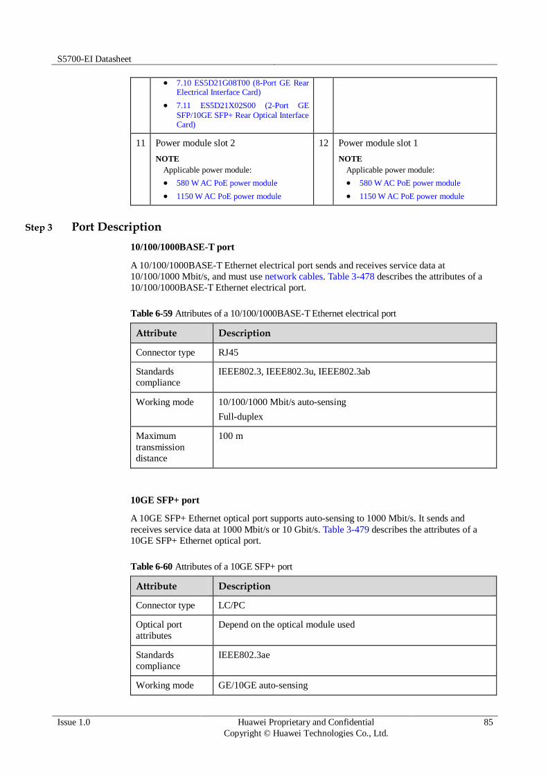
S5700-EI Datasheet
Issue 1.0 Huawei Proprietary and Confidential
Copyright © Huawei Technologies Co., Ltd.
85
7.10 ES5D21G08T00 (8-Port GE Rear Electrical Interface Card)
7.11 ES5D21X02S00 (2-Port GE
SFP/10GE SFP+ Rear Optical Interface Card)
11 Power module slot 2
NOTE
Applicable power module:
580 W AC PoE power module
1150 W AC PoE power module
12 Power module slot 1
NOTE
Applicable power module:
580 W AC PoE power module
1150 W AC PoE power module
Step 3 Port Description
10/100/1000BASE-T port
A 10/100/1000BASE-T Ethernet electrical port sends and receives service data at
10/100/1000 Mbit/s, and must use network cables. Table 3-478 describes the attributes of a
10/100/1000BASE-T Ethernet electrical port.
Table 6-59 Attributes of a 10/100/1000BASE-T Ethernet electrical port
Attribute Description
Connector type RJ45
Standards
compliance
IEEE802.3, IEEE802.3u, IEEE802.3ab
Working mode 10/100/1000 Mbit/s auto-sensing
Full-duplex
Maximum
transmission
distance
100 m
10GE SFP+ port
A 10GE SFP+ Ethernet optical port supports auto-sensing to 1000 Mbit/s. It sends and
receives service data at 1000 Mbit/s or 10 Gbit/s. Table 3-479 describes the attributes of a
10GE SFP+ Ethernet optical port.
Table 6-60 Attributes of a 10GE SFP+ port
Attribute Description
Connector type LC/PC
Optical port
attributes
Depend on the optical module used
Standards
compliance
IEEE802.3ae
Working mode GE/10GE auto-sensing
S5700-EI Datasheet
Issue 1.0 Huawei Proprietary and Confidential
Copyright © Huawei Technologies Co., Ltd.
86
Attribute Description
Full-duplex
Console port
The console port is connected to a console for on-site configuration. The port must use a
console cable. The console port is used when a switch is powered on for the first time. For
details about the attributes of a console port, see Table 3-480.
Table 6-61 Attributes of a console port
Attribute Description
Connector type RJ45
Standards
compliance
RS-232
Working mode Duplex Universal Asynchronous Receiver/Transmitter (UART)
Baud rate 9600 bit/s, 19200 bit/s, 38400 bit/s, 57600 bit/s, or 115200 bit/s
Default value: 9600 bit/s
Mini USB port
The mini USB port is connected to a console for on-site configuration. When both the Mini
USB and console port have a cable connected, only the Mini USB port works.
ETH management port
You can connect a switch to a configuration terminal or network management workstation
through the ETH management port to configure the switch locally or remotely. The port must
use a network cable. You can choose to download the software package through the ETH
management port in the BootROM menu. File transfer through the ETH management port is
faster than transfer through the console port. For details on how to use the ETH management
port, see the Configuration Guide - Basic Configurations. Table 3-481 describes the attributes
of an ETH management port.
Table 6-62 Attributes of an ETH management port
Attribute Description
Connector type RJ45
Standards
compliance
IEEE802.3
Working mode 10/100 Mbit/s auto-sensing
Full duplex
Maximum
transmission distance
100 m
S5700-EI Datasheet
Issue 1.0 Huawei Proprietary and Confidential
Copyright © Huawei Technologies Co., Ltd.
87
USB port
The USB port can have a USB flash drive connected to upgrade the switch, or transfer
configuration files or other files. The USB flash drive used on a switch must comply with
USB 1.1 and support the Linux operating system. Table 3-482 lists the USB flash drives
applicable to a switch.
Table 6-63 USB flash drives applicable to a switch
Capacity
Vendor Model Remarks
4 GB Netac U208 You can buy Netac USB 4 GB flash drives
from Huawei or other vendors.
SanDisk Cruzer Blade Huawei does not offer this USB flash drive,
and you must buy it from other vendors.
Hewlett-
Packard
v218G Huawei does not offer this USB flash drive,
and you must buy it from other vendors.
PNY M1 Huawei does not offer this USB flash drive,
and you must buy it from other vendors.
8 GB Netac U208 Huawei does not offer this USB flash drive,
and you must buy it from other vendors.
Hewlett-
Packard
v225w Huawei does not offer this USB flash drive,
and you must buy it from other vendors.
STEC SLUFD8GU2T
UI
Huawei does not offer this USB flash drive,
and you must buy it from other vendors.
Huawei is not responsible for maintenance service of USB flash drives purchased from other vendors.
Step 4 Indicator Description
The S5710-52C-PWR-EI has the same types of indicators as the S5710-28C-PWR-EI-AC.
For details, see Indicator Description.
Step 5 Power Supply Configuration
The S5710-52C-PWR-EI is a PoE switch and uses 580 W or 1150 W AC PoE power modules.
It has two power module slots. Table 3-483 lists its power supply configurations.
Table 6-64 Power supply configurations
Power Module 1
Power Module 2
Available PoE Power
Maximum Number of Ports (Fully Loaded)
580 W – 369.6 W 802.3af (15.4 W per port):
24

S5700-EI Datasheet
Issue 1.0 Huawei Proprietary and Confidential
Copyright © Huawei Technologies Co., Ltd.
88
Power Module 1
Power Module 2
Available PoE Power
Maximum Number of Ports (Fully Loaded)
802.3at (30 W per port):
12
580 W 580 W 739.2 W 802.3af (15.4 W per port):
48
802.3at (30 W per port): 24
1150 W – 785.4 W 802.3af (15.4 W per port):
48
802.3at (30 W per port): 26
1150 W 1150 W 1440 W 802.3af (15.4 W per port):
48
802.3at (30 W per port): 48
When a switch has two power modules installed, the two power modules work in redundancy mode to provide power for the chassis and in load balancing mode to provide power for PDs.
Figure 3-179 shows the power supply mode of dual AC PoE power modules (PWR1 and
PWR2). After AC power is transmitted to the PWR modules, the PWR modules provide 12 V
and -53 V outputs. The outputs are combined on the motherboard, which then provides 12 V
voltage for the switch and -53 V voltage for the PDs.
Figure 6-27 Power supply by dual AC PoE power modules
PWR2
L N
Motherboard
GND12V
PGND
PWR1
L N PGND
-53V RTN
L:
live wire
N:
neutral wire
PGND: protection
ground
GND: 12 V
reference ground
RTN: -53 V
reference ground
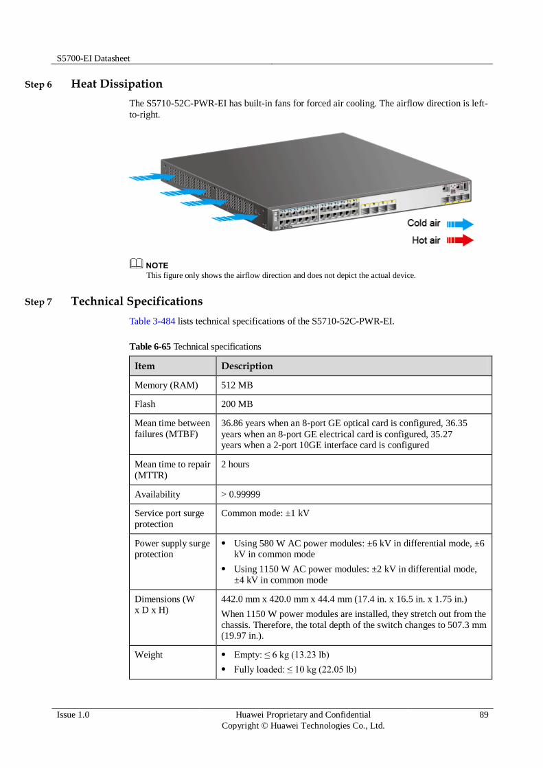
S5700-EI Datasheet
Issue 1.0 Huawei Proprietary and Confidential
Copyright © Huawei Technologies Co., Ltd.
89
Step 6 Heat Dissipation
The S5710-52C-PWR-EI has built-in fans for forced air cooling. The airflow direction is left-
to-right.
This figure only shows the airflow direction and does not depict the actual device.
Step 7 Technical Specifications
Table 3-484 lists technical specifications of the S5710-52C-PWR-EI.
Table 6-65 Technical specifications
Item Description
Memory (RAM) 512 MB
Flash 200 MB
Mean time between
failures (MTBF)
36.86 years when an 8-port GE optical card is configured, 36.35
years when an 8-port GE electrical card is configured, 35.27 years when a 2-port 10GE interface card is configured
Mean time to repair
(MTTR)
2 hours
Availability > 0.99999
Service port surge
protection
Common mode: ±1 kV
Power supply surge protection
Using 580 W AC power modules: ±6 kV in differential mode, ±6 kV in common mode
Using 1150 W AC power modules: ±2 kV in differential mode,
±4 kV in common mode
Dimensions (W
x D x H)
442.0 mm x 420.0 mm x 44.4 mm (17.4 in. x 16.5 in. x 1.75 in.)
When 1150 W power modules are installed, they stretch out from the
chassis. Therefore, the total depth of the switch changes to 507.3 mm (19.97 in.).
Weight Empty: ≤ 6 kg (13.23 lb)
Fully loaded: ≤ 10 kg (22.05 lb)

S5700-EI Datasheet
Issue 1.0 Huawei Proprietary and Confidential
Copyright © Huawei Technologies Co., Ltd.
90
Item Description
Stack ports Four fixed 10GE SFP+ ports on the front panel or ports on the 2-port
10GE rear card
RPS Not supported
PoE Supported
Rated voltage range 100 V AC to 240 V AC, 50/60 Hz
Maximum voltage
range
90 V AC to 264 V AC, 47 Hz to 63 Hz
Maximum power
consumption
(100% throughput,
100% PoE loads, full speed of fans)
Using two 580 W power modules
No card: 1023 W (system power consumption: 283 W, PoE: 740 W)
Two 8-port GE electrical card: 1035 W (system power consumption: 295 W, PoE: 740 W)
Two 8-port GE optical card: 1043 W (system power
consumption: 303 W, PoE: 740 W)
Two 2-port 10GE optical card: 1040 W (system power consumption: 300 W, PoE: 740 W)
Using two 1150 W power modules
No card: 1605 W (system power consumption: 165 W, PoE: 1440 W)
Two 8-port GE electrical card: 1625 W (system power consumption: 185 W, PoE: 1440 W)
Two 8-port GE optical card: 1635 W (system power
consumption: 195 W, PoE: 1440 W)
Two 2-port 10GE optical card: 1633 W (system power consumption: 193 W, PoE: 1440 W)
Operating
temperature
0°C to 50°C (32°F to 122°F) at an altitude of 0-1800 m (0-5096 ft.)
NOTE
When the altitude is 1800-5000 m (5096-16404 ft.), the highest operating temperature reduces by 1°C (1.8°F) every time the altitude increases by 220 m (722 ft.).
Storage
temperature
-40°C to +70°C (-40°F to +158°F)
Noise under normal
temperature (27°C,
sound power)
< 60 dBA
Relative humidity 5% to 95%, noncondensing
Operating altitude 0-5000 m (0-16404 ft.)
Certification EMC certification
Safety certification
Manufacturing certification

S5700-EI Datasheet
Issue 1.0 Huawei Proprietary and Confidential
Copyright © Huawei Technologies Co., Ltd.
91
6.2.5 S5710-52C-PWR-EI-AC
Step 1 Version Mapping
Table 3-485 lists the mapping between the S5710-52C-PWR-EI-AC chassis and software
versions.
Table 6-66 Version mapping
Series Model Software Version
S5710-EI S5710-52C-PWR-EI-AC V200R002C00 to V200R005C02
NOTE
This model does not match V200R003C02, V200R003C10, or V200R005C01.
Step 2 Appearance and Structure
Figure 6-28 S5710-52C-PWR-EI-AC appearance
1 Forty-eight PoE+ 10/100/1000BASE-T
ports
2 Four 10GE SFP+ ports
Applicable modules and cables:
GE optical module
GE-CWDM optical module
GE-DWDM optical module
GE copper module
10GE SFP+ optical module
10GE-CWDM optical module (applicable in V200R005C00)
1 m, 3 m, and 10 m SFP+ high-speed copper cables
3 m and 10 m AOC cables
(applicable in V200R003C00 and later versions)

S5700-EI Datasheet
Issue 1.0 Huawei Proprietary and Confidential
Copyright © Huawei Technologies Co., Ltd.
92
3 ETH management port 4 One mini USB port
5 One console port 6 One USB port
7 Ground screw
NOTE
It is used with a ground cable.
8 Rear card slot 1
NOTE
Card supported:
7.9 ES5D21G08S00 (8-Port GE SFP Rear Optical Interface Card)
7.10 ES5D21G08T00 (8-Port GE Rear Electrical Interface Card)
7.11 ES5D21X02S00 (2-Port GE SFP/10GE SFP+ Rear Optical Interface Card)
9 Rear card slot 2
NOTE
Card supported:
7.9 ES5D21G08S00 (8-Port GE SFP Rear Optical Interface Card)
7.10 ES5D21G08T00 (8-Port GE Rear Electrical Interface Card)
7.11 ES5D21X02S00 (2-Port GE SFP/10GE SFP+ Rear Optical Interface Card)
10 ESN label
NOTE
You can draw it out to view the ESN and MAC address of the switch.
11 Power module slot 2
NOTE
Applicable power module:
580 W AC PoE power module
12 Power module slot 1
NOTE
Applicable power module:
580 W AC PoE power module
Step 3 Port Description
10/100/1000BASE-T port
A 10/100/1000BASE-T Ethernet electrical port sends and receives service data at
10/100/1000 Mbit/s, and must use network cables. Table 3-486 describes the attributes of a
10/100/1000BASE-T Ethernet electrical port.
Table 6-67 Attributes of a 10/100/1000BASE-T Ethernet electrical port
Attribute Description
Connector type RJ45
Standards
compliance
IEEE802.3, IEEE802.3u, IEEE802.3ab
Working mode 10/100/1000 Mbit/s auto-sensing
Full-duplex
Maximum
transmission
distance
100 m

S5700-EI Datasheet
Issue 1.0 Huawei Proprietary and Confidential
Copyright © Huawei Technologies Co., Ltd.
93
10GE SFP+ port
A 10GE SFP+ Ethernet optical port supports auto-sensing to 1000 Mbit/s. It sends and
receives service data at 1000 Mbit/s or 10 Gbit/s. Table 3-487 describes the attributes of a
10GE SFP+ Ethernet optical port.
Table 6-68 Attributes of a 10GE SFP+ port
Attribute Description
Connector type LC/PC
Optical port
attributes
Depend on the optical module used
Standards
compliance
IEEE802.3ae
Working mode GE/10GE auto-sensing
Full-duplex
Console port
The console port is connected to a console for on-site configuration. The port must use a
console cable. The console port is used when a switch is powered on for the first time. For
details about the attributes of a console port, see Table 3-488.
Table 6-69 Attributes of a console port
Attribute Description
Connector type RJ45
Standards
compliance
RS-232
Working mode Duplex Universal Asynchronous Receiver/Transmitter (UART)
Baud rate 9600 bit/s, 19200 bit/s, 38400 bit/s, 57600 bit/s, or 115200 bit/s
Default value: 9600 bit/s
Mini USB port
The mini USB port is connected to a console for on-site configuration. When both the Mini
USB and console port have a cable connected, only the Mini USB port works.
ETH management port
You can connect a switch to a configuration terminal or network management workstation
through the ETH management port to configure the switch locally or remotely. The port must
use a network cable. You can choose to download the software package through the ETH
management port in the BootROM menu. File transfer through the ETH management port is
faster than transfer through the console port. For details on how to use the ETH management

S5700-EI Datasheet
Issue 1.0 Huawei Proprietary and Confidential
Copyright © Huawei Technologies Co., Ltd.
94
port, see the Configuration Guide - Basic Configurations. Table 3-489 describes the attributes
of an ETH management port.
Table 6-70 Attributes of an ETH management port
Attribute Description
Connector type RJ45
Standards
compliance
IEEE802.3
Working mode 10/100 Mbit/s auto-sensing
Full duplex
Maximum
transmission distance
100 m
USB port
The USB port can have a USB flash drive connected to upgrade the switch, or transfer
configuration files or other files. The USB flash drive used on a switch must comply with
USB 1.1 and support the Linux operating system. Table 3-490 lists the USB flash drives
applicable to a switch.
Table 6-71 USB flash drives applicable to a switch
Capacity
Vendor Model Remarks
4 GB Netac U208 You can buy Netac USB 4 GB flash drives
from Huawei or other vendors.
SanDisk Cruzer Blade Huawei does not offer this USB flash drive,
and you must buy it from other vendors.
Hewlett-
Packard
v218G Huawei does not offer this USB flash drive,
and you must buy it from other vendors.
PNY M1 Huawei does not offer this USB flash drive,
and you must buy it from other vendors.
8 GB Netac U208 Huawei does not offer this USB flash drive,
and you must buy it from other vendors.
Hewlett-
Packard
v225w Huawei does not offer this USB flash drive,
and you must buy it from other vendors.
STEC SLUFD8GU2T
UI
Huawei does not offer this USB flash drive,
and you must buy it from other vendors.
Huawei is not responsible for maintenance service of USB flash drives purchased from other vendors.

S5700-EI Datasheet
Issue 1.0 Huawei Proprietary and Confidential
Copyright © Huawei Technologies Co., Ltd.
95
Step 4 Indicator Description
The S5710-52C-PWR-EI-AC has the same types of indicators as the S5710-28C-PWR-EI-AC.
For details, see Indicator Description.
Step 5 Power Supply Configuration
The S5710-52C-PWR-EI-AC is a PoE switch and uses 580 W AC PoE power modules. It has
two power module slots. Table 3-491 lists its power supply configurations.
Table 6-72 Power supply configurations
Power Module 1
Power Module 2
Available PoE Power
Maximum Number of Ports (Fully Loaded)
580 W – 369.6 W 802.3af (15.4 W per port):
24
802.3at (30 W per port): 12
580 W 580 W 739.2 W 802.3af (15.4 W per port):
48
802.3at (30 W per port):
24
When a switch has two power modules installed, the two power modules work in redundancy mode to provide power for the chassis and in load balancing mode to provide power for PDs.
Figure 3-181 shows the power supply mode of dual AC PoE power modules (PWR1 and
PWR2). After AC power is transmitted to the PWR modules, the PWR modules provide 12 V
and -53 V outputs. The outputs are combined on the motherboard, which then provides 12 V
voltage for the switch and -53 V voltage for the PDs.
Figure 6-29 Power supply by dual AC PoE power modules
PWR2
L N
Motherboard
GND12V
PGND
PWR1
L N PGND
-53V RTN
L:
live wire
N:
neutral wire
PGND: protection
ground
GND: 12 V
reference ground
RTN: -53 V
reference ground

S5700-EI Datasheet
Issue 1.0 Huawei Proprietary and Confidential
Copyright © Huawei Technologies Co., Ltd.
96
Step 6 Heat Dissipation
The S5710-52C-PWR-EI-AC has built-in fans for forced air cooling. The airflow direction is
left-to-right.
This figure only shows the airflow direction and does not depict the actual device.
Step 7 Technical Specifications
Table 3-492 lists technical specifications of the S5710-52C-PWR-EI-AC.
Table 6-73 Technical specifications
Item Description
Memory (RAM) 512 MB
Flash 200 MB
Mean time between
failures (MTBF)
36.86 years when an 8-port GE optical card is configured, 36.35
years when an 8-port GE electrical card is configured, 35.27 years when a 2-port 10GE interface card is configured
Mean time to repair
(MTTR)
2 hours
Availability > 0.99999
Service port surge
protection
Common mode: ±1 kV
Power supply surge protection
±6 kV in differential mode, ±6 kV in common mode
Dimensions (W
x D x H)
442.0 mm x 420.0 mm x 44.4 mm (17.4 in. x 16.5 in. x 1.75 in.)
Weight Empty: ≤ 6 kg (13.23 lb)
Fully loaded: ≤ 10 kg (22.05 lb)
Stack ports Four fixed 10GE SFP+ ports on the front panel or ports on the 2-port
10GE rear card
RPS Not supported

S5700-EI Datasheet
Issue 1.0 Huawei Proprietary and Confidential
Copyright © Huawei Technologies Co., Ltd.
97
Item Description
PoE Supported
Rated voltage range 100 V AC to 240 V AC, 50/60 Hz
Maximum voltage
range
90 V AC to 264 V AC, 47 Hz to 63 Hz
Maximum power
consumption
(100% throughput,
100% PoE loads, full speed of fans)
No card: 1023 W (system power consumption: 283 W, PoE: 740
W)
Two 8-port GE electrical card: 1035 W (system power
consumption: 295 W, PoE: 740 W)
Two 8-port GE optical card: 1043 W (system power consumption: 303 W, PoE: 740 W)
Two 2-port 10GE optical card: 1040 W (system power consumption: 300 W, PoE: 740 W)
Operating
temperature
0°C to 50°C (32°F to 122°F) at an altitude of 0-1800 m (0-5096 ft.)
NOTE
When the altitude is 1800-5000 m (5096-16404 ft.), the highest operating temperature reduces by 1°C (1.8°F) every time the altitude increases by 220 m (722 ft.).
Storage
temperature
-40°C to +70°C (-40°F to +158°F)
Noise under normal
temperature (27°C,
sound power)
< 60 dBA
Relative humidity 5% to 95%, noncondensing
Operating altitude 0-5000 m (0-16404 ft.)
Certification EMC certification
Safety certification
Manufacturing certification
6.3 S5720-EI
6.3.1 S5720-36C-EI-AC
Step 1 Version Mapping
Table 3-493 lists the mapping between the S5720-36C-EI-AC chassis and software versions.

S5700-EI Datasheet
Issue 1.0 Huawei Proprietary and Confidential
Copyright © Huawei Technologies Co., Ltd.
98
Table 6-74 Version mapping
Series Model Software Version
S5720-EI S5720-C-
EI
S5720-36C-EI-AC V200R007C00 and later versions
NOTE
This model does not match V200R007C10.
Step 2 Appearance and Structure
Figure 6-30 S5720-36C-EI-AC appearance
1 Twenty-four 10/100/1000BASE-T
ports
2 Four combo ports (10/100/1000BASE-
T + 100/1000BASE-X)
Modules applicable to the combo optical ports:
FE optical module
GE optical module
GE-CWDM optical module
GE-DWDM optical module
3 Four 10GE SFP+ ports
Applicable modules and cables:
GE optical module
GE-CWDM optical module
GE-DWDM optical module
GE copper module
10GE SFP+ optical module
(OSXD22N00 not supported)
10GE-CWDM optical module
1 m, 3 m, and 10 m SFP+ high-speed copper cables
5 m SFP+ high-speed copper cable
(applicable in V200R009C00 and
4 One mini USB port

S5700-EI Datasheet
Issue 1.0 Huawei Proprietary and Confidential
Copyright © Huawei Technologies Co., Ltd.
99
later versions)
3 m and 10 m AOC cables
5 One console port
NOTE
It is used with a console cable. The console cable is not delivered with the switch and needs to be separately purchased if needed.
6 ETH management port
7 One USB port 8 Ground screw
NOTE
It is used with a ground cable.
9 ESN label
NOTE
You can draw it out to view the ESN and MAC address of the switch.
10 Rear card slot
NOTE
Card supported:
7.17 ES5D21X02S01 (2-Port 10 Gig SFP+ Rear Interface Card, Used in S5720-EI Series)
7.18 ES5D21X02T01 (2-Port 10 Gig
RJ45 Rear Interface Card, Used in S5720-EI Series)
7.19 ES5D21VST000 (Dedicated Stack
Card with 2*QSFP+ Interface, Used in S5720-EI Series)
11 Fan slot
NOTE
Applicable fan module: 6.3 FAN-028A-B Fan Module
12 Power module slot 2
NOTE
Applicable power modules:
150 W AC power module
150 W DC power module
13 Power module slot 1
NOTE
Applicable power modules:
150 W AC power module
150 W DC power module
- -
Step 3 Port Description
10/100/1000BASE-T port
A 10/100/1000BASE-T Ethernet electrical port sends and receives service data at
10/100/1000 Mbit/s, and must use network cables. Table 3-494 describes the attributes of a
10/100/1000BASE-T Ethernet electrical port.
Table 6-75 Attributes of a 10/100/1000BASE-T Ethernet electrical port
Attribute Description
Connector type RJ45
Standards compliance
IEEE802.3, IEEE802.3u, IEEE802.3ab

S5700-EI Datasheet
Issue 1.0 Huawei Proprietary and Confidential
Copyright © Huawei Technologies Co., Ltd.
100
Attribute Description
Working mode 10/100/1000 Mbit/s auto-sensing
Full-duplex
Maximum
transmission
distance
100 m
Combo port
A combo port refers to a pair of ports consisting of an optical Ethernet port and an electrical
Ethernet port on the panel. Each combo port matches only one internal forwarding port. A
combo port can be configured as an electrical port or an optical port, but only one port can be
active at a time. When one port is active, the other port is shut down.
By default, a combo port works in auto mode, in which the port type is determined as follows:
If the optical port has no optical module installed and the electrical port has no network cable connected, the port type depends on which port is connected first. If the electrical port is connected by a network cable first, the electrical port is used for data switching. If the optical port has an optical module installed first, the optical port is used for data switching.
If the electrical port has a network cable connected and is in Up state, the electrical port is still used for data switching when the optical port has an optical module installed.
If the optical port, no matter in Up or Down state, has an optical module installed, the optical port is still used for data switching when the electrical port has a network cable connected.
If the optical port has an optical module installed and the electrical port has a network cable connected, the optical port is used for data switching after the switch restarts.
You can configure a combo port as an electrical or optical port using the combo-port command.
10GE SFP+ port
A 10GE SFP+ Ethernet optical port supports auto-sensing to 1000 Mbit/s. It sends and
receives service data at 1000 Mbit/s or 10 Gbit/s. Table 3-495 describes the attributes of a
10GE SFP+ Ethernet optical port.
Table 6-76 Attributes of a 10GE SFP+ port
Attribute Description
Connector type LC/PC
Optical port
attributes
Depend on the optical module used
Standards
compliance
IEEE802.3ae
Working mode GE/10GE auto-sensing
Full-duplex
Console port

S5700-EI Datasheet
Issue 1.0 Huawei Proprietary and Confidential
Copyright © Huawei Technologies Co., Ltd.
101
The console port is connected to a console for on-site configuration. The port must use a
console cable. The console port is used when a switch is powered on for the first time. For
details about the attributes of a console port, see Table 3-496.
Table 6-77 Attributes of a console port
Attribute Description
Connector type RJ45
Standards
compliance
RS-232
Working mode Duplex Universal Asynchronous Receiver/Transmitter (UART)
Baud rate 9600 bit/s, 19200 bit/s, 38400 bit/s, 57600 bit/s, or 115200 bit/s
Default value: 9600 bit/s
Mini USB port
The mini USB port is connected to a console for on-site configuration. When both the Mini
USB and console port have a cable connected, only the Mini USB port works.
ETH management port
You can connect a switch to a configuration terminal or network management workstation
through the ETH management port to configure the switch locally or remotely. The port must
use a network cable. You can choose to download the software package through the ETH
management port in the BootLoad menu. File transfer through the ETH management port is
faster than transfer through the console port. For details on how to use the ETH management
port, see the Configuration Guide - Basic Configurations. Table 3-497 describes the attributes
of an ETH management port.
Table 6-78 Attributes of an ETH management port
Attribute Description
Connector type RJ45
Standards
compliance
IEEE802.3
Working mode 10/100 Mbit/s auto-sensing
Full duplex
Maximum
transmission distance
100 m
USB port
The USB port can have a USB flash drive connected to upgrade the switch, or transfer
configuration files or other files. The USB port of the S5720-EI does not support USB 1.1 and

S5700-EI Datasheet
Issue 1.0 Huawei Proprietary and Confidential
Copyright © Huawei Technologies Co., Ltd.
102
can only connect to a USB flash drive that complies with USB 2.0 and supports the Linux
operating system.
Step 4 Indicator Description
The S5720-36C-EI-AC has similar indicators to those on the S5720-36C-PWR-EI-AC, except
that the S5720-36C-EI-AC does not have a PoE mode indicator. For details, see
Indicator Description.
Step 5 Power Supply Configuration
The S5720-36C-EI-AC uses pluggable power modules. It can be configured with a single
power module or double power modules for 1+1 power redundancy. Pluggable AC and DC
power modules can be used together in the same switch.
Figure 3-183 shows the power supply connections of dual DC power modules. After DC
power is transmitted to the PWR module, the PWR module provides 12 V output voltage, and
the motherboard provides power for the entire device.
Figure 6-31 Power supply connections of dual DC power modules
PWR2
NEG RTN
Motherboard
GND12V
PWR1
NEG RTN
NEG: negative cable RTN: positive cable GND: 12 V reference ground
Figure 3-184 shows the power supply connections of dual non-PoE AC power modules. After
AC power is transmitted to the PWR module, the PWR module provides 12 V output voltage,
and the motherboard provides power for the entire device.
Figure 6-32 Power supply connections of dual non-PoE AC power modules
PWR2
L N
Motherboard
GND12V
PGND
PWR1
L N PGND
L:
Live wire
N:
Neutral wire
PGND: Protective
ground wire
GND: 12 V reference
ground

S5700-EI Datasheet
Issue 1.0 Huawei Proprietary and Confidential
Copyright © Huawei Technologies Co., Ltd.
103
Step 6 Heat Dissipation
The S5720-36C-EI-AC uses pluggable fan modules for forced air cooling. Air flows in from
the left side, right side, and front panel, and exhausts from the rear panel.
Step 7 Technical Specifications
Table 3-498 lists technical specifications of the S5720-36C-EI-AC.
Table 6-79 Technical specifications
Item Description
Memory (RAM) 2 GB
Flash 340 MB
Mean time between
failures (MTBF)
80.05 years when no card is configured; 73.65 years when a 2-port
10GE SFP+ interface card is configured; 71.58 years when a 2-port
10GE RJ45 interface card is configured; 71.74 years when a stack
card is configured
Mean time to repair
(MTTR)
2 hours
Availability > 0.99999
Service port surge
protection
Common mode: ±6 kV
Power supply surge
protection
Using AC power modules: ±6 kV in differential mode, ±6 kV in
common mode
Using DC power modules: ±1 kV in differential mode, ±2 kV in common mode
Dimensions (W
x D x H)
442.0 mm x 420.0 mm x 44.4 mm (17.4 in. x 16.5 in. x 1.74 in.)
Weight Empty: ≤ 8 kg (17.64 lb)
Fully loaded: ≤ 12 kg (26.46 lb)

S5700-EI Datasheet
Issue 1.0 Huawei Proprietary and Confidential
Copyright © Huawei Technologies Co., Ltd.
104
Item Description
Stack ports Ports on the 2-port 10GE SFP+ rear interface card
Ports on the 2-port 10GE RJ45 rear interface card
Ports on the 2-port QSFP+ rear stack card
RPS Not supported
PoE Not supported
Rated voltage range 100 V AC to 240 V AC, 50/60 Hz
-48 V DC to -60 V DC
Maximum voltage
range
90 V AC to 264 V AC, 47 Hz to 63 Hz
-36 V DC to -72 V DC
Maximum power
consumption
(100% throughput, full speed of fans)
75.8 W
Operating
temperature
0°C to 45°C (32°F to 113°F) at an altitude of 0-1800 m (0-5096 ft.)
NOTE
When the altitude is 1800-5000 m (5096-16404 ft.), the highest operating temperature reduces by 1°C (1.8°F) every time the altitude increases by 220 m (722 ft.).
Storage
temperature
-40°C to +70°C (-40°F to +158°F)
Noise under normal
temperature (27°C,
sound power)
< 51.2 dBA
Relative humidity 5% to 95%, noncondensing
Operating altitude AC power modules configured: 0-5000 m (0-16404 ft.)
DC power modules configured: 0-2000 m (0-6562 ft.)
Certification EMC certification
Safety certification
Manufacturing certification
6.3.2 S5720-36C-EI-DC
Step 1 Version Mapping
Table 3-499 lists the mapping between the S5720-36C-EI-DC chassis and software versions.

S5700-EI Datasheet
Issue 1.0 Huawei Proprietary and Confidential
Copyright © Huawei Technologies Co., Ltd.
105
Table 6-80 Version mapping
Series Model Software Version
S5720-EI S5720-C-
EI
S5720-36C-EI-DC V200R009C00 and later versions
Step 2 Appearance and Structure
Figure 6-33 S5720-36C-EI-DC appearance
1 Twenty-four 10/100/1000BASE-T
ports
2 Four combo ports (10/100/1000BASE-
T + 100/1000BASE-X)
Modules applicable to the combo optical ports:
FE optical module
GE optical module
GE-CWDM optical module
GE-DWDM optical module
3 Four 10GE SFP+ ports
Applicable modules and cables:
GE optical module
GE-CWDM optical module
GE-DWDM optical module
GE copper module
10GE SFP+ optical module
(OSXD22N00 not supported)
10GE-CWDM optical module
1 m, 3 m, and 10 m SFP+ high-speed copper cables
5 m SFP+ high-speed copper cable
(applicable in V200R009C00 and
later versions)
3 m and 10 m AOC cables
4 One mini USB port

S5700-EI Datasheet
Issue 1.0 Huawei Proprietary and Confidential
Copyright © Huawei Technologies Co., Ltd.
106
5 One console port
NOTE
It is used with a console cable. The console
cable is not delivered with the switch and needs to be separately purchased if needed.
6 ETH management port
7 One USB port 8 Ground screw
NOTE
It is used with a ground cable.
9 ESN label
NOTE
You can draw it out to view the ESN and MAC address of the switch.
10 Rear card slot
NOTE
Card supported:
7.17 ES5D21X02S01 (2-Port 10 Gig SFP+ Rear Interface Card, Used in S5720-EI Series)
7.18 ES5D21X02T01 (2-Port 10 Gig RJ45 Rear Interface Card, Used in S5720-EI Series)
7.19 ES5D21VST000 (Dedicated Stack Card with 2*QSFP+ Interface, Used in S5720-EI Series)
11 Fan slot
NOTE
Applicable fan module: 6.3 FAN-028A-B Fan Module
12 Power module slot 2
NOTE
Applicable power modules:
150 W AC power module
150 W DC power module
13 Power module slot 1
NOTE
Applicable power modules:
150 W AC power module
150 W DC power module
- -
Step 3 Port Description
10/100/1000BASE-T port
A 10/100/1000BASE-T Ethernet electrical port sends and receives service data at
10/100/1000 Mbit/s, and must use network cables. Table 3-500 describes the attributes of a
10/100/1000BASE-T Ethernet electrical port.
Table 6-81 Attributes of a 10/100/1000BASE-T Ethernet electrical port
Attribute Description
Connector type RJ45
Standards
compliance
IEEE802.3, IEEE802.3u, IEEE802.3ab
Working mode 10/100/1000 Mbit/s auto-sensing
Full-duplex

S5700-EI Datasheet
Issue 1.0 Huawei Proprietary and Confidential
Copyright © Huawei Technologies Co., Ltd.
107
Attribute Description
Maximum
transmission distance
100 m
Combo port
A combo port refers to a pair of ports consisting of an optical Ethernet port and an electrical
Ethernet port on the panel. Each combo port matches only one internal forwarding port. A
combo port can be configured as an electrical port or an optical port, but only one port can be
active at a time. When one port is active, the other port is shut down.
By default, a combo port works in auto mode, in which the port type is determined as follows:
If the optical port has no optical module installed and the electrical port has no network cable
connected, the port type depends on which port is connected first. If the electrical port is connected by a network cable first, the electrical port is used for data switching. If the optical port has an optical module installed first, the optical port is used for data switching.
If the electrical port has a network cable connected and is in Up state, the electrical port is still used for data switching when the optical port has an optical module installed.
If the optical port, no matter in Up or Down state, has an optical module installed, the optical port is still used for data switching when the electrical port has a network cable connected.
If the optical port has an optical module installed and the electrical port has a network cable connected, the optical port is used for data switching after the switch restarts.
You can configure a combo port as an electrical or optical port using the combo-port command.
10GE SFP+ port
A 10GE SFP+ Ethernet optical port supports auto-sensing to 1000 Mbit/s. It sends and
receives service data at 1000 Mbit/s or 10 Gbit/s. Table 3-501 describes the attributes of a
10GE SFP+ Ethernet optical port.
Table 6-82 Attributes of a 10GE SFP+ port
Attribute Description
Connector type LC/PC
Optical port
attributes
Depend on the optical module used
Standards
compliance
IEEE802.3ae
Working mode GE/10GE auto-sensing
Full-duplex
Console port
The console port is connected to a console for on-site configuration. The port must use a
console cable. The console port is used when a switch is powered on for the first time. For
details about the attributes of a console port, see Table 3-502.

S5700-EI Datasheet
Issue 1.0 Huawei Proprietary and Confidential
Copyright © Huawei Technologies Co., Ltd.
108
Table 6-83 Attributes of a console port
Attribute Description
Connector type RJ45
Standards
compliance
RS-232
Working mode Duplex Universal Asynchronous Receiver/Transmitter (UART)
Baud rate 9600 bit/s, 19200 bit/s, 38400 bit/s, 57600 bit/s, or 115200 bit/s
Default value: 9600 bit/s
Mini USB port
The mini USB port is connected to a console for on-site configuration. When both the Mini
USB and console port have a cable connected, only the Mini USB port works.
ETH management port
You can connect a switch to a configuration terminal or network management workstation
through the ETH management port to configure the switch locally or remotely. The port must
use a network cable. You can choose to download the software package through the ETH
management port in the BootLoad menu. File transfer through the ETH management port is
faster than transfer through the console port. For details on how to use the ETH management
port, see the Configuration Guide - Basic Configurations. Table 3-503 describes the attributes
of an ETH management port.
Table 6-84 Attributes of an ETH management port
Attribute Description
Connector type RJ45
Standards
compliance
IEEE802.3
Working mode 10/100 Mbit/s auto-sensing
Full duplex
Maximum
transmission distance
100 m
USB port
The USB port can have a USB flash drive connected to upgrade the switch, or transfer
configuration files or other files. The USB port of the S5720-EI does not support USB 1.1 and
can only connect to a USB flash drive that complies with USB 2.0 and supports the Linux
operating system.

S5700-EI Datasheet
Issue 1.0 Huawei Proprietary and Confidential
Copyright © Huawei Technologies Co., Ltd.
109
Step 4 Indicator Description
The S5720-36C-EI-DC has similar indicators to those on the S5720-36C-PWR-EI-AC, except
that the S5720-56C-EI-DC does not have a PoE mode indicator. For details, see
Indicator Description.
Step 5 Power Supply Configuration
The S5720-36C-EI-DC uses pluggable power modules. It can be configured with a single
power module or double power modules for 1+1 power redundancy. Pluggable AC and DC
power modules can be used together in the same switch.
Figure 3-186 shows the power supply connections of dual DC power modules. After DC
power is transmitted to the PWR module, the PWR module provides 12 V output voltage, and
the motherboard provides power for the entire device.
Figure 6-34 Power supply connections of dual DC power modules
PWR2
NEG RTN
Motherboard
GND12V
PWR1
NEG RTN
NEG: negative cable RTN: positive cable GND: 12 V reference ground
Figure 3-187 shows the power supply connections of dual non-PoE AC power modules. After
AC power is transmitted to the PWR module, the PWR module provides 12 V output voltage,
and the motherboard provides power for the entire device.
Figure 6-35 Power supply connections of dual non-PoE AC power modules
PWR2
L N
Motherboard
GND12V
PGND
PWR1
L N PGND
L:
Live wire
N:
Neutral wire
PGND: Protective
ground wire
GND: 12 V reference
ground

S5700-EI Datasheet
Issue 1.0 Huawei Proprietary and Confidential
Copyright © Huawei Technologies Co., Ltd.
110
Step 6 Heat Dissipation
The S5720-36C-EI-DC uses pluggable fan modules for forced air cooling. Air flows in from
the left side, right side, and front panel, and exhausts from the rear panel.
Step 7 Technical Specifications
Table 3-504 lists technical specifications of the S5720-36C-EI-DC.
Table 6-85 Technical specifications
Item Description
Memory (RAM) 2 GB
Flash 340 MB
Mean time between
failures (MTBF)
80.05 years when no card is configured; 73.65 years when a 2-port
10GE SFP+ interface card is configured; 71.58 years when a 2-port
10GE RJ45 interface card is configured; 71.74 years when a stack card is configured
Mean time to repair
(MTTR)
2 hours
Availability > 0.99999
Service port surge
protection
Common mode: ±6 kV
Power supply surge
protection
Using AC power modules: ±6 kV in differential mode, ±6 kV in
common mode
Using DC power modules: ±1 kV in differential mode, ±2 kV in common mode
Dimensions (W
x D x H)
442.0 mm x 420.0 mm x 44.4 mm (17.4 in. x 16.5 in. x 1.74 in.)
Weight Empty: ≤ 8 kg (17.64 lb)
Fully loaded: ≤ 12 kg (26.46 lb)
Stack ports Ports on the 2-port 10GE SFP+ rear interface card

S5700-EI Datasheet
Issue 1.0 Huawei Proprietary and Confidential
Copyright © Huawei Technologies Co., Ltd.
111
Item Description
Ports on the 2-port 10GE RJ45 rear interface card
Ports on the 2-port QSFP+ rear stack card
RPS Not supported
PoE Not supported
Rated voltage range 100 V AC to 240 V AC, 50/60 Hz
-48 V DC to -60 V DC
Maximum voltage
range
90 V AC to 264 V AC, 47 Hz to 63 Hz
-36 V DC to -72 V DC
Maximum power
consumption
(100% throughput, full speed of fans)
75.8 W
Operating
temperature
0°C to 45°C (32°F to 113°F) at an altitude of 0-1800 m (0-5096 ft.)
NOTE
When the altitude is 1800-5000 m (5096-16404 ft.), the highest operating
temperature reduces by 1°C (1.8°F) every time the altitude increases by 220 m (722 ft.).
Storage
temperature
-40°C to +70°C (-40°F to +158°F)
Noise under normal
temperature (27°C, sound power)
< 51.2 dBA
Relative humidity 5% to 95%, noncondensing
Operating altitude AC power modules configured: 0-5000 m (0-16404 ft.)
DC power modules configured: 0-2000 m (0-6562 ft.)
Certification EMC certification
Safety certification
Manufacturing certification
6.3.3 S5720-36C-EI-28S-AC
Step 1 Version Mapping
Table 3-505 lists the mapping between the S5720-36C-EI-28S-AC chassis and software
versions.

S5700-EI Datasheet
Issue 1.0 Huawei Proprietary and Confidential
Copyright © Huawei Technologies Co., Ltd.
112
Table 6-86 Version mapping
Series Model Software Version
S5720-EI S5720-C-
EI
S5720-36C-EI-28S-
AC
V200R007C00 and later versions
NOTE
This model does not match V200R007C10.
Step 2 Appearance and Structure
Figure 6-36 S5720-36C-EI-28S-AC appearance
1 Twenty-four 100/1000BASE-X ports
Applicable modules:
FE optical module
GE optical module
GE-CWDM optical module
GE copper module
2 Four combo ports (10/100/1000BASE-
T + 100/1000BASE-X)
Modules applicable to the combo optical ports:
FE optical module
GE optical module
GE-CWDM optical module
3 Four 10GE SFP+ ports
Applicable modules and cables:
GE optical module
GE-CWDM optical module
GE-DWDM optical module
GE copper module
10GE SFP+ optical module
(OSXD22N00 not supported)
10GE-CWDM optical module
1 m, 3 m, and 10 m SFP+ high-speed copper cables
5 m SFP+ high-speed copper cable
(applicable in V200R009C00 and
later versions)
4 One mini USB port

S5700-EI Datasheet
Issue 1.0 Huawei Proprietary and Confidential
Copyright © Huawei Technologies Co., Ltd.
113
3 m and 10 m AOC cables
5 One console port
NOTE
It is used with a console cable. The console cable is not delivered with the switch and needs to be separately purchased if needed.
6 ETH management port
7 One USB port 8 Ground screw
NOTE
It is used with a ground cable.
9 ESN label
NOTE
You can draw it out to view the ESN and MAC address of the switch.
10 Rear card slot
NOTE
Card supported:
7.17 ES5D21X02S01 (2-Port 10 Gig
SFP+ Rear Interface Card, Used in S5720-EI Series)
7.18 ES5D21X02T01 (2-Port 10 Gig
RJ45 Rear Interface Card, Used in S5720-EI Series)
7.19 ES5D21VST000 (Dedicated Stack
Card with 2*QSFP+ Interface, Used in S5720-EI Series)
11 Fan slot
NOTE
Applicable fan module: 6.3 FAN-028A-B Fan Module
12 Power module slot 2
NOTE
Applicable power modules:
150 W AC power module
150 W DC power module
13 Power module slot 1
NOTE
Applicable power modules:
150 W AC power module
150 W DC power module
- -
Step 3 Port Description
100/1000BASE-X port
A 100/1000BASE-X port can send and receive data at 100 Mbit/s or 1000 Mbit/s. Table 3-506
describes the attributes of a 100/1000BASE-X port.
Table 6-87 Attributes of a 100/1000BASE-X port
Attribute Description
Connector type LC/PC
Optical interface
attributes
Depend on the optical module used
Standards compliance
IEEE802.3z

S5700-EI Datasheet
Issue 1.0 Huawei Proprietary and Confidential
Copyright © Huawei Technologies Co., Ltd.
114
Attribute Description
Working mode 100/1000 Mbit/s auto-sensing
Full-duplex
Combo port
A combo port consists of an optical Ethernet port and an electrical Ethernet port on the panel.
Each combo port matches only one internal forwarding port. The electrical and optical ports
of a combo port are multiplexed, and only one of them can work at a time. When one of the
Ethernet ports is working, the other port is shut down.
By default, a combo port works in auto mode, in which the port type is determined as follows:
If the optical port has no optical module installed and the electrical port has no network cable connected, the port type depends on which port is connected first. If the electrical port is connected by a network cable first, the electrical port is used for data switching. If the optical port has an optical module installed first, the optical port is used for data switching.
If the electrical port has a network cable connected and is in Up state, the electrical port is still used for data switching when the optical port has an optical module installed.
If the optical port, no matter in Up or Down state, has an optical module installed, the optical port is still used for data switching when the electrical port has a network cable connected.
If the optical port has an optical module installed and the electrical port has a network cable connected, the optical port is used for data switching after the switch restarts.
You can configure a combo port as an electrical or optical port using the combo-port command.
10GE SFP+ port
A 10GE SFP+ Ethernet optical port supports auto-sensing to 1000 Mbit/s. It sends and
receives service data at 1000 Mbit/s or 10 Gbit/s. Table 3-507 describes the attributes of a
10GE SFP+ Ethernet optical port.
Table 6-88 Attributes of a 10GE SFP+ port
Attribute Description
Connector type LC/PC
Optical port
attributes
Depend on the optical module used
Standards
compliance
IEEE802.3ae
Working mode GE/10GE auto-sensing
Full-duplex
Console port
The console port is connected to a console for on-site configuration. The port must use a
console cable. The console port is used when a switch is powered on for the first time. For
details about the attributes of a console port, see Table 3-508.

S5700-EI Datasheet
Issue 1.0 Huawei Proprietary and Confidential
Copyright © Huawei Technologies Co., Ltd.
115
Table 6-89 Attributes of a console port
Attribute Description
Connector type RJ45
Standards
compliance
RS-232
Working mode Duplex Universal Asynchronous Receiver/Transmitter (UART)
Baud rate 9600 bit/s, 19200 bit/s, 38400 bit/s, 57600 bit/s, or 115200 bit/s
Default value: 9600 bit/s
Mini USB port
The mini USB port is connected to a console for on-site configuration. When both the Mini
USB and console port have a cable connected, only the Mini USB port works.
ETH management port
You can connect a switch to a configuration terminal or network management workstation
through the ETH management port to configure the switch locally or remotely. The port must
use a network cable. You can choose to download the software package through the ETH
management port in the BootLoad menu. File transfer through the ETH management port is
faster than transfer through the console port. For details on how to use the ETH management
port, see the Configuration Guide - Basic Configurations. Table 3-509 describes the attributes
of an ETH management port.
Table 6-90 Attributes of an ETH management port
Attribute Description
Connector type RJ45
Standards
compliance
IEEE802.3
Working mode 10/100 Mbit/s auto-sensing
Full duplex
Maximum
transmission distance
100 m
USB port
The USB port can have a USB flash drive connected to upgrade the switch, or transfer
configuration files or other files. The USB port of the S5720-EI does not support USB 1.1 and
can only connect to a USB flash drive that complies with USB 2.0 and supports the Linux
operating system.
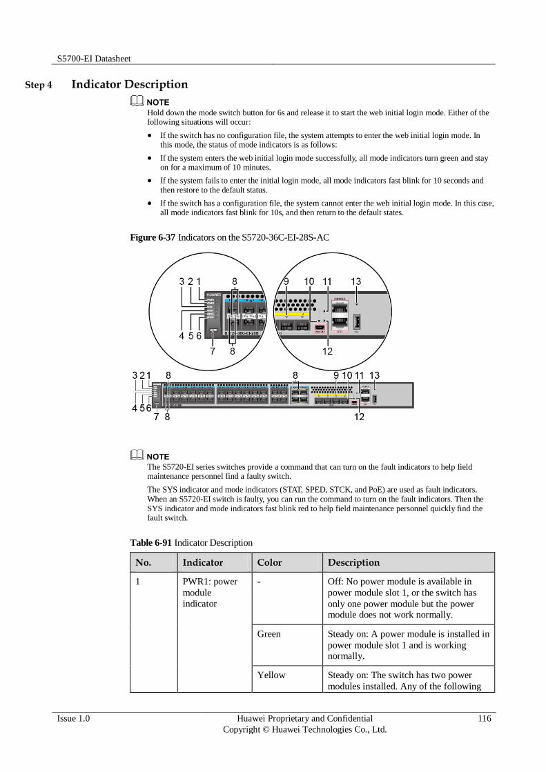
S5700-EI Datasheet
Issue 1.0 Huawei Proprietary and Confidential
Copyright © Huawei Technologies Co., Ltd.
116
Step 4 Indicator Description
Hold down the mode switch button for 6s and release it to start the web initial login mode. Either of the following situations will occur:
If the switch has no configuration file, the system attempts to enter the web initial login mode. In this mode, the status of mode indicators is as follows:
If the system enters the web initial login mode successfully, all mode indicators turn green and stay on for a maximum of 10 minutes.
If the system fails to enter the initial login mode, all mode indicators fast blink for 10 seconds and then restore to the default status.
If the switch has a configuration file, the system cannot enter the web initial login mode. In this case, all mode indicators fast blink for 10s, and then return to the default states.
Figure 6-37 Indicators on the S5720-36C-EI-28S-AC
The S5720-EI series switches provide a command that can turn on the fault indicators to help field maintenance personnel find a faulty switch.
The SYS indicator and mode indicators (STAT, SPED, STCK, and PoE) are used as fault indicators. When an S5720-EI switch is faulty, you can run the command to turn on the fault indicators. Then the SYS indicator and mode indicators fast blink red to help field maintenance personnel quickly find the fault switch.
Table 6-91 Indicator Description
No. Indicator Color Description
1 PWR1: power
module
indicator
- Off: No power module is available in
power module slot 1, or the switch has
only one power module but the power module does not work normally.
Green Steady on: A power module is installed in
power module slot 1 and is working normally.
Yellow Steady on: The switch has two power
modules installed. Any of the following

S5700-EI Datasheet
Issue 1.0 Huawei Proprietary and Confidential
Copyright © Huawei Technologies Co., Ltd.
117
No. Indicator Color Description
situations occurs in power module slot 1:
A power module is available in this
slot but its power switch is in the OFF position.
A power module is available in this
slot but it is not connected to a power source.
The power module in this slot has failed.
2 PWR2: power
module
indicator
- Off: No power module is available in
power module slot 2, or the switch has
only one power module but the power module does not work normally.
Green Steady on: A power module is installed in
power module slot 2 and is working normally.
Yellow Steady on: The switch has two power
modules installed. Any of the following
situations occurs in power module slot 2:
A power module is available in this
slot but its power switch is in the OFF position.
A power module is available in this
slot but it is not connected to a power
source.
The power module in this slot has failed.
3 SYS: system
status indicator
- Off: The system is not running.
Green Fast blinking: The system is starting.
Slow blinking: The system is running normally.
Red Steady on: The system does not work
normally after registration, or a fan alarm or temperature alarm has been generated.
4 STAT: status
indicator
Green Off: The status mode is not selected.
Steady on: The status mode (default
mode) is selected. In this mode,
service port indicators show the port link or activity state.
5 SPED: speed
indicator
Green Off: The speed mode is not selected.
Steady on: The speed mode is
selected. In this mode, service port
indicators show port speeds. After 45
seconds, the service port indicators
S5700-EI Datasheet
Issue 1.0 Huawei Proprietary and Confidential
Copyright © Huawei Technologies Co., Ltd.
118
No. Indicator Color Description
automatically restore to the status mode.
6 STCK: stack
indicator
Green If you are not changing the indicator
mode (default state):
Off: The switch is the standby or
slave switch in a stack or a standalone
switch with the stacking function disabled.
Blinking: The switch is the master
switch in a stack or a standalone
switch with the stacking function enabled.
If you are changing the indicator mode:
Off: The stack mode is not selected.
Steady on: The stack mode is
selected. The switch is a standby or
slave switch in a stack, and the service
port indicators show the stack ID of the switch.
Blinking: The switch is the master
switch in a stack or a standalone
switch, and the service port indicators
show the stack ID of the master switch.
After 45 seconds, the service port
indicators automatically restore to the
status mode.
7 MODE: mode
switch button
- When you press this button once, the
service port indicators change to the
speed mode and show the speed of each service port.
When you press this button a second
time, the service port indicators
change to the stack mode and show the stack ID of the local switch.
When you press the button a third
time, the service port indicators
restore to the default mode, and the STAT indicator turns green.
If you do not press the MODE
button within 45 seconds, the service port
indicators restore to the default mode. In
this case, the STAT indicator is steady
green, the SPED indicator is off, and the
STCK indicator is off or blinking green.
8 Service port
indicator (two
Meanings of service port indicators vary in different modes. For details, see Table 3-511.

S5700-EI Datasheet
Issue 1.0 Huawei Proprietary and Confidential
Copyright © Huawei Technologies Co., Ltd.
119
No. Indicator Color Description
indicators for each port)
NOTE
Arrowheads show the
positions of ports. A down arrowhead indicates a port at the bottom, and an up arrowhead indicates a port at the top.
9 Service port
indicator (one
indicator for each port)
Meanings of service port indicators vary in different modes.
For details, see Table 3-512.
10 Mini USB
indicator
Green Off: The Mini USB port is disabled,
and the console port is enabled.
Steady on: The Mini USB port is enabled.
When the Mini USB indicator is steady
green, the console indicator is off.
11 Console
indicator
Green Off: The console port is disabled, and
the Mini USB port is enabled.
Steady on: The console port is enabled (default state).
When the console indicator is steady green, the Mini USB indicator is off.
12 ETH port
indicator
Green Off: The ETH management port is not
connected.
Steady on: The ETH management
port is connected.
Blinking: The port is sending or receiving data.
13 USB-based
deployment indicator
- Off:
No USB flash drive is connected to the switch.
The USB port is damaged.
The indicator is damaged.
The USB flash drive does not have
any configuration file and cannot be
used for deployment.
The switch has been upgraded using the USB flash drive and is restarting.

S5700-EI Datasheet
Issue 1.0 Huawei Proprietary and Confidential
Copyright © Huawei Technologies Co., Ltd.
120
No. Indicator Color Description
Green Steady on: A USB-based deployment
has been completed.
Blinking: The system is reading data from the USB flash drive.
Yellow Steady on: The switch has copied all the
required files and completed the file
check. The USB flash drive can be
removed from the switch.
Red Blinking: An error has occurred when the
system is executing the configuration file or reading data from the USB flash drive.
Table 6-92 Description of service port indicators in different modes (two indicators for each port)
Display Mode Color Description
Status - Off: The port is not connected or has
been shut down.
Green Steady on: The port is connected.
Yellow Blinking: The port is sending or receiving
data.
Speed Green and
yellow
Off: The port is not connected or has
been shut down.
Both steady on:
10M/100M/1000M port: The port is operating at 10/100 Mbit/s.
1000M/10GE port: The port is operating at 1000 Mbit/s.
Both blinking:
10M/100M/1000M port: The port is operating at 1000 Mbit/s.
1000M/10GE port: The port is
operating at 10 Gbit/s.
Stack Green and
yellow
Off: Service port indicators do not
show the stack ID of the switch.
If both indicators are steady on, the switch is not a master switch:
If the indicator of a port is steady
on, the number of this port is the
stack ID of the switch.
If the first nine port indicators are
steady on, the stack ID of the switch is 0.

S5700-EI Datasheet
Issue 1.0 Huawei Proprietary and Confidential
Copyright © Huawei Technologies Co., Ltd.
121
Display Mode Color Description
If both indicators are blinking, the switch is a master switch:
If the indicator of a port is
blinking, the number of this port is
the stack ID of the switch.
If the first nine port indicators are
blinking, the stack ID of the switch is 0.
Table 6-93 Description of service port indicators in different modes (one indicator for each port)
Display Mode Color Description
Status Green Off: The port is not connected or has
been shut down.
Steady on: The port is connected.
Blinking: The port is sending or receiving data.
Speed Green Off: The port is not connected or has
been shut down.
Steady on:
10M/100M/1000M port: The port is operating at 10/100 Mbit/s.
1000M/10GE port: The port is
operating at 1000 Mbit/s.
Blinking:
10M/100M/1000M port: The port is operating at 1000 Mbit/s.
1000M/10GE port: The port is operating at 10 Gbit/s.
Stack Green Off: Port indicators do not show the
stack ID of the switch.
If the indicator is steady on, the
switch is not a master switch:
If the indicator of a port is steady
on, the number of this port is the stack ID of the switch.
If the first nine port indicators are
steady on, the stack ID of the switch is 0.
If the indicator is blinking, the switch is a master switch:
If the indicator of a port is
blinking, the number of this port is the stack ID of the switch.
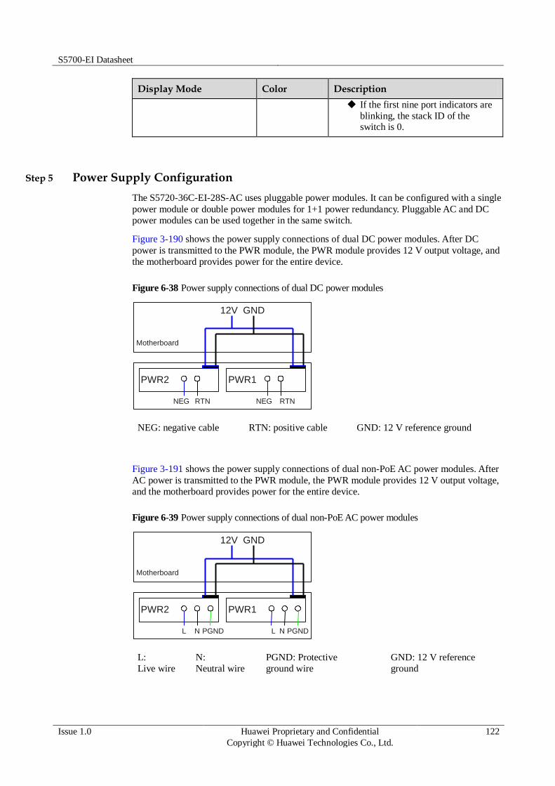
S5700-EI Datasheet
Issue 1.0 Huawei Proprietary and Confidential
Copyright © Huawei Technologies Co., Ltd.
122
Display Mode Color Description
If the first nine port indicators are
blinking, the stack ID of the switch is 0.
Step 5 Power Supply Configuration
The S5720-36C-EI-28S-AC uses pluggable power modules. It can be configured with a single
power module or double power modules for 1+1 power redundancy. Pluggable AC and DC
power modules can be used together in the same switch.
Figure 3-190 shows the power supply connections of dual DC power modules. After DC
power is transmitted to the PWR module, the PWR module provides 12 V output voltage, and
the motherboard provides power for the entire device.
Figure 6-38 Power supply connections of dual DC power modules
PWR2
NEG RTN
Motherboard
GND12V
PWR1
NEG RTN
NEG: negative cable RTN: positive cable GND: 12 V reference ground
Figure 3-191 shows the power supply connections of dual non-PoE AC power modules. After
AC power is transmitted to the PWR module, the PWR module provides 12 V output voltage,
and the motherboard provides power for the entire device.
Figure 6-39 Power supply connections of dual non-PoE AC power modules
PWR2
L N
Motherboard
GND12V
PGND
PWR1
L N PGND
L:
Live wire
N:
Neutral wire
PGND: Protective
ground wire
GND: 12 V reference
ground

S5700-EI Datasheet
Issue 1.0 Huawei Proprietary and Confidential
Copyright © Huawei Technologies Co., Ltd.
123
Step 6 Heat Dissipation
The S5720-36C-EI-28S-AC uses pluggable fan modules for forced air cooling. Air flows in
from the left side, right side, and front panel, and exhausts from the rear panel.
This figure only shows the airflow direction and does not depict the actual device.
Step 7 Technical Specifications
Table 3-513 lists technical specifications of the S5720-36C-EI-28S-AC.
Table 6-94 Technical specifications
Item Description
Memory (RAM) 2 GB
Flash 340 MB
Mean time between
failures (MTBF)
85.45 years when no card is configured; 78.2 years when a 2-port
10GE SFP+ interface card is configured; 75.87 years when a 2-port
10GE RJ45 interface card is configured; 76.05 years when a stack
card is configured
Mean time to repair
(MTTR)
2 hours
Availability > 0.99999
Service port surge
protection
Common mode: ±6 kV
Power supply surge
protection
Using AC power modules: ±6 kV in differential mode, ±6 kV in
common mode
Using DC power modules: ±1 kV in differential mode, ±2 kV in common mode
Dimensions (W
x D x H)
442.0 mm x 420.0 mm x 44.4 mm (17.4 in. x 16.5 in. x 1.74 in.)
Weight Empty: ≤ 8 kg (17.64 lb)
Fully loaded: ≤ 12 kg (26.46 lb)

S5700-EI Datasheet
Issue 1.0 Huawei Proprietary and Confidential
Copyright © Huawei Technologies Co., Ltd.
124
Item Description
Stack ports Ports on the 2-port 10GE SFP+ rear interface card
Ports on the 2-port 10GE RJ45 rear interface card
Ports on the 2-port QSFP+ rear stack card
RPS Not supported
PoE Not supported
Rated voltage range 100 V AC to 240 V AC, 50/60 Hz
-48 V DC to -60 V DC
Maximum voltage
range
90 V AC to 264 V AC, 47 Hz to 63 Hz
-36 V DC to -72 V DC
Maximum power
consumption
(100% throughput, full speed of fans)
83.9 W
Operating
temperature
0°C to 45°C (32°F to 113°F) at an altitude of 0-1800 m (0-5096 ft.)
NOTE
When the altitude is 1800-5000 m (5096-16404 ft.), the highest operating temperature reduces by 1°C (1.8°F) every time the altitude increases by 220 m (722 ft.).
Storage
temperature
-40°C to +70°C (-40°F to +158°F)
Noise under normal
temperature (27°C,
sound power)
< 51.2 dBA
Relative humidity 5% to 95%, noncondensing
Operating altitude AC power modules configured: 0-5000 m (0-16404 ft.)
DC power modules configured: 0-2000 m (0-6562 ft.)
Certification EMC certification
Safety certification
Manufacturing certification
6.3.4 S5720-36C-EI-28S-DC
Step 1 Version Mapping
Table 3-514 lists the mapping between the S5720-36C-EI-28S-DC chassis and software
versions.

S5700-EI Datasheet
Issue 1.0 Huawei Proprietary and Confidential
Copyright © Huawei Technologies Co., Ltd.
125
Table 6-95 Version mapping
Series Model Software Version
S5720-EI S5720-C-
EI
S5720-36C-EI-28S-
DC
V200R009C00 and later versions
Step 2 Appearance and Structure
Figure 6-40 S5720-36C-EI-28S-DC appearance
1 Twenty-four 100/1000BASE-X ports
Applicable modules:
FE optical module
GE optical module
GE-CWDM optical module
GE copper module
2 Four combo ports (10/100/1000BASE-
T + 100/1000BASE-X)
Modules applicable to the combo optical ports:
FE optical module
GE optical module
GE-CWDM optical module
3 Four 10GE SFP+ ports
Applicable modules and cables:
GE optical module
GE-CWDM optical module
GE-DWDM optical module
GE copper module
10GE SFP+ optical module
(OSXD22N00 not supported)
10GE-CWDM optical module
1 m, 3 m, and 10 m SFP+ high-speed copper cables
5 m SFP+ high-speed copper cable
(applicable in V200R009C00 and
later versions)
3 m and 10 m AOC cables
4 One mini USB port
5 One console port 6 ETH management port

S5700-EI Datasheet
Issue 1.0 Huawei Proprietary and Confidential
Copyright © Huawei Technologies Co., Ltd.
126
NOTE
It is used with a console cable. The console cable is not delivered with the switch and needs to be separately purchased if needed.
7 One USB port 8 Ground screw
NOTE
It is used with a ground cable.
9 ESN label
NOTE
You can draw it out to view the ESN and MAC address of the switch.
10 Rear card slot
NOTE
Card supported:
7.17 ES5D21X02S01 (2-Port 10 Gig SFP+ Rear Interface Card, Used in S5720-EI Series)
7.18 ES5D21X02T01 (2-Port 10 Gig RJ45 Rear Interface Card, Used in S5720-EI Series)
7.19 ES5D21VST000 (Dedicated Stack Card with 2*QSFP+ Interface, Used in S5720-EI Series)
11 Fan slot
NOTE
Applicable fan module: 6.3 FAN-028A-B Fan Module
12 Power module slot 2
NOTE
Applicable power modules:
150 W AC power module
150 W DC power module
13 Power module slot 1
NOTE
Applicable power modules:
150 W AC power module
150 W DC power module
- -
Step 3 Port Description
100/1000BASE-X port
A 100/1000BASE-X port can send and receive data at 100 Mbit/s or 1000 Mbit/s. Table 3-515
describes the attributes of a 100/1000BASE-X port.
Table 6-96 Attributes of a 100/1000BASE-X port
Attribute Description
Connector type LC/PC
Optical interface
attributes
Depend on the optical module used
Standards
compliance
IEEE802.3z
Working mode 100/1000 Mbit/s auto-sensing
Full-duplex

S5700-EI Datasheet
Issue 1.0 Huawei Proprietary and Confidential
Copyright © Huawei Technologies Co., Ltd.
127
Combo port
A combo port consists of an optical Ethernet port and an electrical Ethernet port on the panel.
Each combo port matches only one internal forwarding port. The electrical and optical ports
of a combo port are multiplexed, and only one of them can work at a time. When one of the
Ethernet ports is working, the other port is shut down.
By default, a combo port works in auto mode, in which the port type is determined as follows:
If the optical port has no optical module installed and the electrical port has no network cable connected, the port type depends on which port is connected first. If the electrical port is connected
by a network cable first, the electrical port is used for data switching. If the optical port has an optical module installed first, the optical port is used for data switching.
If the electrical port has a network cable connected and is in Up state, the electrical port is still used for data switching when the optical port has an optical module installed.
If the optical port, no matter in Up or Down state, has an optical module installed, the optical port is still used for data switching when the electrical port has a network cable connected.
If the optical port has an optical module installed and the electrical port has a network cable connected, the optical port is used for data switching after the switch restarts.
You can configure a combo port as an electrical or optical port using the combo-port command.
10GE SFP+ port
A 10GE SFP+ Ethernet optical port supports auto-sensing to 1000 Mbit/s. It sends and
receives service data at 1000 Mbit/s or 10 Gbit/s. Table 3-516 describes the attributes of a
10GE SFP+ Ethernet optical port.
Table 6-97 Attributes of a 10GE SFP+ port
Attribute Description
Connector type LC/PC
Optical port
attributes
Depend on the optical module used
Standards
compliance
IEEE802.3ae
Working mode GE/10GE auto-sensing
Full-duplex
Console port
The console port is connected to a console for on-site configuration. The port must use a
console cable. The console port is used when a switch is powered on for the first time. For
details about the attributes of a console port, see Table 3-517.
Table 6-98 Attributes of a console port
Attribute Description
Connector type RJ45

S5700-EI Datasheet
Issue 1.0 Huawei Proprietary and Confidential
Copyright © Huawei Technologies Co., Ltd.
128
Attribute Description
Standards
compliance
RS-232
Working mode Duplex Universal Asynchronous Receiver/Transmitter (UART)
Baud rate 9600 bit/s, 19200 bit/s, 38400 bit/s, 57600 bit/s, or 115200 bit/s
Default value: 9600 bit/s
Mini USB port
The mini USB port is connected to a console for on-site configuration. When both the Mini
USB and console port have a cable connected, only the Mini USB port works.
ETH management port
You can connect a switch to a configuration terminal or network management workstation
through the ETH management port to configure the switch locally or remotely. The port must
use a network cable. You can choose to download the software package through the ETH
management port in the BootLoad menu. File transfer through the ETH management port is
faster than transfer through the console port. For details on how to use the ETH management
port, see the Configuration Guide - Basic Configurations. Table 3-518 describes the attributes
of an ETH management port.
Table 6-99 Attributes of an ETH management port
Attribute Description
Connector type RJ45
Standards
compliance
IEEE802.3
Working mode 10/100 Mbit/s auto-sensing
Full duplex
Maximum
transmission distance
100 m
USB port
The USB port can have a USB flash drive connected to upgrade the switch, or transfer
configuration files or other files. The USB port of the S5720-EI does not support USB 1.1 and
can only connect to a USB flash drive that complies with USB 2.0 and supports the Linux
operating system.
Step 4 Indicator Description
The S5720-36C-EI-28S-DC have the same types of indicators as the S5720-36C-EI-28S-AC.
For details, see Indicator Description.

S5700-EI Datasheet
Issue 1.0 Huawei Proprietary and Confidential
Copyright © Huawei Technologies Co., Ltd.
129
Step 5 Power Supply Configuration
The S5720-36C-EI-28S-DC uses pluggable power modules. It can be configured with a single
power module or double power modules for 1+1 power redundancy. Pluggable AC and DC
power modules can be used together in the same switch.
Figure 3-193 shows the power supply connections of dual DC power modules. After DC
power is transmitted to the PWR module, the PWR module provides 12 V output voltage, and
the motherboard provides power for the entire device.
Figure 6-41 Power supply connections of dual DC power modules
PWR2
NEG RTN
Motherboard
GND12V
PWR1
NEG RTN
NEG: negative cable RTN: positive cable GND: 12 V reference ground
Figure 3-194 shows the power supply connections of dual non-PoE AC power modules. After
AC power is transmitted to the PWR module, the PWR module provides 12 V output voltage,
and the motherboard provides power for the entire device.
Figure 6-42 Power supply connections of dual non-PoE AC power modules
PWR2
L N
Motherboard
GND12V
PGND
PWR1
L N PGND
L:
Live wire
N:
Neutral wire
PGND: Protective
ground wire
GND: 12 V reference
ground
Step 6 Heat Dissipation
The S5720-36C-EI-28S-DC uses pluggable fan modules for forced air cooling. Air flows in
from the left side, right side, and front panel, and exhausts from the rear panel.

S5700-EI Datasheet
Issue 1.0 Huawei Proprietary and Confidential
Copyright © Huawei Technologies Co., Ltd.
130
This figure only shows the airflow direction and does not depict the actual device.
Step 7 Technical Specifications
Table 3-519 lists technical specifications of the S5720-36C-EI-28S-DC.
Table 6-100 Technical specifications
Item Description
Memory (RAM) 2 GB
Flash 340 MB
Mean time between
failures (MTBF)
85.45 years when no card is configured; 78.2 years when a 2-port
10GE SFP+ interface card is configured; 75.87 years when a 2-port
10GE RJ45 interface card is configured; 76.05 years when a stack card is configured
Mean time to repair
(MTTR)
2 hours
Availability > 0.99999
Service port surge
protection
Common mode: ±6 kV
Power supply surge
protection
Using AC power modules: ±6 kV in differential mode, ±6 kV in
common mode
Using DC power modules: ±1 kV in differential mode, ±2 kV in common mode
Dimensions (W
x D x H)
442.0 mm x 420.0 mm x 44.4 mm (17.4 in. x 16.5 in. x 1.74 in.)
Weight Empty: ≤ 8 kg (17.64 lb)
Fully loaded: ≤ 12 kg (26.46 lb)
Stack ports Ports on the 2-port 10GE SFP+ rear interface card
Ports on the 2-port 10GE RJ45 rear interface card
Ports on the 2-port QSFP+ rear stack card

S5700-EI Datasheet
Issue 1.0 Huawei Proprietary and Confidential
Copyright © Huawei Technologies Co., Ltd.
131
Item Description
RPS Not supported
PoE Not supported
Rated voltage range 100 V AC to 240 V AC, 50/60 Hz
-48 V DC to -60 V DC
Maximum voltage
range
90 V AC to 264 V AC, 47 Hz to 63 Hz
-36 V DC to -72 V DC
Maximum power
consumption
(100% throughput, full speed of fans)
83.9 W
Operating
temperature
0°C to 45°C (32°F to 113°F) at an altitude of 0-1800 m (0-5096 ft.)
NOTE
When the altitude is 1800-5000 m (5096-16404 ft.), the highest operating
temperature reduces by 1°C (1.8°F) every time the altitude increases by 220 m (722 ft.).
Storage
temperature
-40°C to +70°C (-40°F to +158°F)
Noise under normal
temperature (27°C, sound power)
< 51.2 dBA
Relative humidity 5% to 95%, noncondensing
Operating altitude AC power modules configured: 0-5000 m (0-16404 ft.)
DC power modules configured: 0-2000 m (0-6562 ft.)
Certification EMC certification
Safety certification
Manufacturing certification
6.3.5 S5720-36C-PWR-EI-AC
Step 1 Version Mapping
Table 3-520 lists the mapping between the S5720-36C-PWR-EI-AC chassis and software
versions.
Table 6-101 Version mapping
Series Model Software Version
S5720-EI S5720-C-
EI
S5720-36C-PWR-EI-
AC
V200R007C00 and later versions
NOTE
This model does not match

S5700-EI Datasheet
Issue 1.0 Huawei Proprietary and Confidential
Copyright © Huawei Technologies Co., Ltd.
132
Series Model Software Version
V200R007C10.
Step 2 Appearance and Structure
Figure 6-43 S5720-36C-PWR-EI-AC appearance
1 Twenty-four PoE+ 10/100/1000BASE-
T ports
2 Four combo ports (10/100/1000BASE-
T (PoE+) + 100/1000BASE-X)
Modules applicable to the combo
optical ports:
FE optical module
GE optical module
GE-CWDM optical module
GE-DWDM optical module
3 Four 10GE SFP+ ports
Applicable modules and cables:
GE optical module
GE-CWDM optical module
GE-DWDM optical module
GE copper module
10GE SFP+ optical module
(OSXD22N00 not supported)
10GE-CWDM optical module
1 m, 3 m, and 10 m SFP+ high-speed copper cables
5 m SFP+ high-speed copper cable
(applicable in V200R009C00 and later versions)
3 m and 10 m AOC cables
4 One mini USB port
5 One console port
NOTE
6 ETH management port

S5700-EI Datasheet
Issue 1.0 Huawei Proprietary and Confidential
Copyright © Huawei Technologies Co., Ltd.
133
It is used with a console cable. The console cable is not delivered with the switch and needs to be separately purchased if needed.
7 One USB port 8 Ground screw
NOTE
It is used with a ground cable.
9 ESN label
NOTE
You can draw it out to view the ESN and MAC address of the switch.
10 Rear card slot
NOTE
Card supported:
7.17 ES5D21X02S01 (2-Port 10 Gig SFP+ Rear Interface Card, Used in S5720-EI Series)
7.18 ES5D21X02T01 (2-Port 10 Gig RJ45 Rear Interface Card, Used in S5720-EI Series)
7.19 ES5D21VST000 (Dedicated Stack Card with 2*QSFP+ Interface, Used in S5720-EI Series)
11 Fan slot
NOTE
Applicable fan module: 6.3 FAN-028A-B Fan Module
12 Power module slot 2
NOTE
Applicable power modules:
500 W AC PoE power module
650 W DC PoE power module
13 Power module slot 1
NOTE
Applicable power modules:
500 W AC PoE power module
650 W DC PoE power module
- -
Step 3 Port Description
10/100/1000BASE-T port
A 10/100/1000BASE-T Ethernet electrical port sends and receives service data at
10/100/1000 Mbit/s, and must use network cables. Table 3-521 describes the attributes of a
10/100/1000BASE-T Ethernet electrical port.
Table 6-102 Attributes of a 10/100/1000BASE-T Ethernet electrical port
Attribute Description
Connector type RJ45
Standards
compliance
IEEE802.3, IEEE802.3u, IEEE802.3ab
Working mode 10/100/1000 Mbit/s auto-sensing
Full-duplex
Maximum
transmission
100 m

S5700-EI Datasheet
Issue 1.0 Huawei Proprietary and Confidential
Copyright © Huawei Technologies Co., Ltd.
134
Attribute Description
distance
Combo port
A combo port refers to a pair of ports consisting of an optical Ethernet port and an electrical
Ethernet port on the panel. Each combo port matches only one internal forwarding port. A
combo port can be configured as an electrical port or an optical port, but only one port can be
active at a time. When one port is active, the other port is shut down.
By default, a combo port works in auto mode, in which the port type is determined as follows:
If the optical port has no optical module installed and the electrical port has no network cable connected, the port type depends on which port is connected first. If the electrical port is connected by a network cable first, the electrical port is used for data switching. If the optical port has an optical module installed first, the optical port is used for data switching.
If the electrical port has a network cable connected and is in Up state, the electrical port is still used for data switching when the optical port has an optical module installed.
If the optical port, no matter in Up or Down state, has an optical module installed, the optical port is still used for data switching when the electrical port has a network cable connected.
If the optical port has an optical module installed and the electrical port has a network cable connected, the optical port is used for data switching after the switch restarts.
You can configure a combo port as an electrical or optical port using the combo-port command.
10GE SFP+ port
A 10GE SFP+ Ethernet optical port supports auto-sensing to 1000 Mbit/s. It sends and
receives service data at 1000 Mbit/s or 10 Gbit/s. Table 3-522 describes the attributes of a
10GE SFP+ Ethernet optical port.
Table 6-103 Attributes of a 10GE SFP+ port
Attribute Description
Connector type LC/PC
Optical port
attributes
Depend on the optical module used
Standards
compliance
IEEE802.3ae
Working mode GE/10GE auto-sensing
Full-duplex
Console port
The console port is connected to a console for on-site configuration. The port must use a
console cable. The console port is used when a switch is powered on for the first time. For
details about the attributes of a console port, see Table 3-523.

S5700-EI Datasheet
Issue 1.0 Huawei Proprietary and Confidential
Copyright © Huawei Technologies Co., Ltd.
135
Table 6-104 Attributes of a console port
Attribute Description
Connector type RJ45
Standards
compliance
RS-232
Working mode Duplex Universal Asynchronous Receiver/Transmitter (UART)
Baud rate 9600 bit/s, 19200 bit/s, 38400 bit/s, 57600 bit/s, or 115200 bit/s
Default value: 9600 bit/s
Mini USB port
The mini USB port is connected to a console for on-site configuration. When both the Mini
USB and console port have a cable connected, only the Mini USB port works.
ETH management port
You can connect a switch to a configuration terminal or network management workstation
through the ETH management port to configure the switch locally or remotely. The port must
use a network cable. You can choose to download the software package through the ETH
management port in the BootLoad menu. File transfer through the ETH management port is
faster than transfer through the console port. For details on how to use the ETH management
port, see the Configuration Guide - Basic Configurations. Table 3-524 describes the attributes
of an ETH management port.
Table 6-105 Attributes of an ETH management port
Attribute Description
Connector type RJ45
Standards
compliance
IEEE802.3
Working mode 10/100 Mbit/s auto-sensing
Full duplex
Maximum
transmission distance
100 m
USB port
The USB port can have a USB flash drive connected to upgrade the switch, or transfer
configuration files or other files. The USB port of the S5720-EI does not support USB 1.1 and
can only connect to a USB flash drive that complies with USB 2.0 and supports the Linux
operating system.

S5700-EI Datasheet
Issue 1.0 Huawei Proprietary and Confidential
Copyright © Huawei Technologies Co., Ltd.
136
Step 4 Indicator Description
Hold down the mode switch button for 6s and release it to start the web initial login mode. Either of the following situations will occur:
If the switch has no configuration file, the system attempts to enter the web initial login mode. In this mode, the status of mode indicators is as follows:
If the system enters the web initial login mode successfully, all mode indicators turn green and stay on for a maximum of 10 minutes.
If the system fails to enter the initial login mode, all mode indicators fast blink for 10 seconds and then restore to the default status.
If the switch has a configuration file, the system cannot enter the web initial login mode. In this case, all mode indicators fast blink for 10s, and then return to the default states.
Figure 6-44 Indicators on the S5720-36C-PWR-EI-AC
The S5720-EI series switches provide a command that can turn on the fault indicators to help field maintenance personnel find a faulty switch.
The SYS indicator and mode indicators (STAT, SPED, STCK, and PoE) are used as fault indicators. When an S5720-EI switch is faulty, you can run the command to turn on the fault indicators. Then the SYS indicator and mode indicators fast blink red to help field maintenance personnel quickly find the fault switch.
Table 6-106 Indicator Description
No. Indicator Color Description
1 PWR1: power
module indicator
- Off: No power module is available in
power module slot 1, or the switch has
only one power module but the power module does not work normally.
Green Steady on: A power module is installed in
power module slot 1 and is working
normally.
Yellow Steady on: The switch has two power
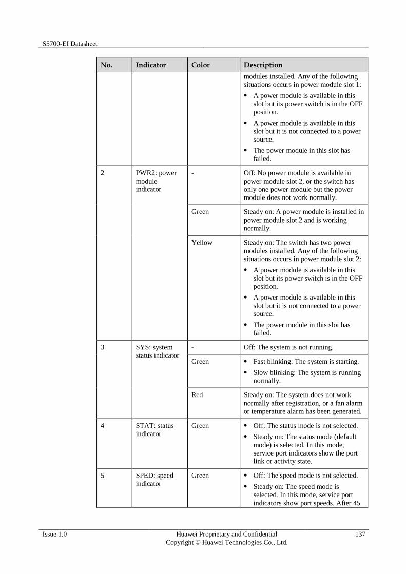
S5700-EI Datasheet
Issue 1.0 Huawei Proprietary and Confidential
Copyright © Huawei Technologies Co., Ltd.
137
No. Indicator Color Description
modules installed. Any of the following situations occurs in power module slot 1:
A power module is available in this
slot but its power switch is in the OFF
position.
A power module is available in this
slot but it is not connected to a power source.
The power module in this slot has failed.
2 PWR2: power
module indicator
- Off: No power module is available in
power module slot 2, or the switch has
only one power module but the power module does not work normally.
Green Steady on: A power module is installed in
power module slot 2 and is working
normally.
Yellow Steady on: The switch has two power
modules installed. Any of the following situations occurs in power module slot 2:
A power module is available in this
slot but its power switch is in the OFF
position.
A power module is available in this
slot but it is not connected to a power source.
The power module in this slot has failed.
3 SYS: system
status indicator
- Off: The system is not running.
Green Fast blinking: The system is starting.
Slow blinking: The system is running normally.
Red Steady on: The system does not work
normally after registration, or a fan alarm
or temperature alarm has been generated.
4 STAT: status
indicator
Green Off: The status mode is not selected.
Steady on: The status mode (default
mode) is selected. In this mode,
service port indicators show the port link or activity state.
5 SPED: speed
indicator
Green Off: The speed mode is not selected.
Steady on: The speed mode is
selected. In this mode, service port
indicators show port speeds. After 45

S5700-EI Datasheet
Issue 1.0 Huawei Proprietary and Confidential
Copyright © Huawei Technologies Co., Ltd.
138
No. Indicator Color Description
seconds, the service port indicators
automatically restore to the status mode.
6 STCK: stack
indicator
Green If you are not changing the indicator
mode (default state):
Off: The switch is the standby or
slave switch in a stack or a standalone
switch with the stacking function disabled.
Blinking: The switch is the master
switch in a stack or a standalone
switch with the stacking function enabled.
If you are changing the indicator mode:
Off: The stack mode is not selected.
Steady on: The stack mode is
selected. The switch is a standby or
slave switch in a stack, and the service
port indicators show the stack ID of the switch.
Blinking: The switch is the master
switch in a stack or a standalone
switch, and the service port indicators
show the stack ID of the master switch.
After 45 seconds, the service port
indicators automatically restore to the status mode.
7 PoE: PoE mode
indicator
Green Off: The PoE mode is not selected.
Steady on: The service port indicators
show the PoE status. After 45
seconds, the service port indicators
automatically restore to the status mode.
8 MODE: mode
switch button
- When you press this button once, the
service port indicators change to the
speed mode and show the speed of
each service port.
When you press this button a second
time, the service port indicators
change to the stack mode and show
the stack ID of the local switch.
When you press this button a third
time, the service port indicators
change to the PoE mode and show the PoE status of ports.
When you press this button a fourth

S5700-EI Datasheet
Issue 1.0 Huawei Proprietary and Confidential
Copyright © Huawei Technologies Co., Ltd.
139
No. Indicator Color Description
time, the service port indicators
restore to the default mode, and the STAT indicator turns green.
If you do not press the MODE
button within 45 seconds, the service port
indicators restore to the default mode. In
this case, the STAT indicator is steady
green, the SPED and PoE indicators are
off, and the STCK indicator is off or blinking green.
9 Service port
indicator (one
indicator for each port)
Meanings of service port indicators vary in different modes.
For details, see Table 3-526.
10 Mini USB
indicator
Green Off: The Mini USB port is disabled,
and the console port is enabled.
Steady on: The Mini USB port is enabled.
When the Mini USB indicator is steady green, the console indicator is off.
11 Console
indicator
Green Off: The console port is disabled, and
the Mini USB port is enabled.
Steady on: The console port is enabled (default state).
When the console indicator is steady green, the Mini USB indicator is off.
12 ETH port
indicator
Green Off: The ETH management port is not
connected.
Steady on: The ETH management port is connected.
Blinking: The ETH management port
is sending or receiving data.
13 USB-based
deployment indicator
- Off:
No USB flash drive is connected to
the switch.
The USB port is damaged.
The indicator is damaged.
The USB flash drive does not have
any configuration file and cannot be used for deployment.
The switch has been upgraded using
the USB flash drive and is restarting.
Green Steady on: A USB-based deployment
has been completed.
Blinking: The system is reading data

S5700-EI Datasheet
Issue 1.0 Huawei Proprietary and Confidential
Copyright © Huawei Technologies Co., Ltd.
140
No. Indicator Color Description
from the USB flash drive.
Yellow Steady on: The switch has copied all the
required files and completed the file
check. The USB flash drive can be removed from the switch.
Red Blinking: An error has occurred when the
system is executing the configuration file
or reading data from the USB flash drive.
Table 6-107 Description of service port indicators in different modes (one indicator for each port)
Display Mode Color Description
Status Green Off: The port is not connected or has
been shut down.
Steady on: The port is connected.
Blinking: The port is sending or
receiving data.
Speed Green Off: The port is not connected or has
been shut down.
Steady on:
10M/100M/1000M port: The port is operating at 10/100 Mbit/s.
1000M/10GE port: The port is operating at 1000 Mbit/s.
Blinking:
10M/100M/1000M port: The port is
operating at 1000 Mbit/s.
1000M/10GE port: The port is operating at 10 Gbit/s.
PoE - Off: The port does not provide PoE
power.
Green Steady on: The port is providing PoE
power.
Yellow Steady on: The PoE function is
disabled on the port.
Blinking: A PoE fault has occurred.
For example, an incompatible PD is
connected to the port.
Green and
yellow
Blinking green and yellow alternately:
The port cannot provide power to a PD.
The possible reasons include:
The power of the PD exceeds the

S5700-EI Datasheet
Issue 1.0 Huawei Proprietary and Confidential
Copyright © Huawei Technologies Co., Ltd.
141
Display Mode Color Description
maximum power or power threshold of the port.
The total power consumption of PDs
has reached the maximum power of
the switch.
The manual power management mode
is used and the port is not enabled to provide power to the PD.
Stack Green Off: Port indicators do not show the
stack ID of the switch.
If the indicator is steady on, the
switch is not a master switch:
If the indicator of a port is steady
on, the number of this port is the stack ID of the switch.
If the first nine port indicators are
steady on, the stack ID of the
switch is 0.
If the indicator is blinking, the switch is a master switch:
If the indicator of a port is
blinking, the number of this port is
the stack ID of the switch.
If the first nine port indicators are
blinking, the stack ID of the switch is 0.
Step 5 Power Supply Configuration
The S5720-36C-PWR-EI-AC is a PoE switch. It has two power module slots, each of which
can have a 500 W or 650 W power module installed. A power module can provide 369.6 W of
PoE power for powered devices (PDs). A 500 W AC power module and a 650 W DC power
module can be used together in the switch. Table 3-527 lists its power supply configurations.
Table 6-108 Power supply configurations
Power Module 1
Power Module 2
Available PoE Power
Maximum Number of Ports (Fully Loaded)
500 W or 650
W
- 369.6 W 802.3af (15.4 W per port):
24
802.3at (30 W per port): 12
500 W or 650
W
500 W or 650
W
739.2 W 802.3af (15.4 W per port):
28
802.3at (30 W per port):

S5700-EI Datasheet
Issue 1.0 Huawei Proprietary and Confidential
Copyright © Huawei Technologies Co., Ltd.
142
Power Module 1
Power Module 2
Available PoE Power
Maximum Number of Ports (Fully Loaded)
24
When a switch has two power modules installed, the two power modules work in redundancy mode to provide power for the chassis and in load balancing mode to provide power for PDs.
Figure 3-197 shows the power supply mode of dual AC PoE power modules (PWR1 and
PWR2). After AC power is transmitted to the PWR modules, the PWR modules provide 12 V
and -53 V outputs. The outputs are combined on the motherboard, which then provides 12 V
voltage for the switch and -53 V voltage for the PDs.
Figure 6-45 Power supply by dual AC PoE power modules
PWR2
L N
Motherboard
GND12V
PGND
PWR1
L N PGND
-53V RTN
L:
live wire
N:
neutral wire
PGND: protection
ground
GND: 12 V
reference ground
RTN: -53 V
reference ground
Figure 3-198 shows the power supply connections of dual DC PoE power modules. After DC
power is transmitted to the PWR module, the PWR module provides 12 V and -53 V output
voltages, and the motherboard provides 12 V voltage for the entire device and -53 V voltage
for the PDs.
Figure 6-46 Power supply connections of dual DC PoE power modules
PWR2
NEG RTN
Motherboard
GND12V
PWR1
-53V RTN
NEG RTN

S5700-EI Datasheet
Issue 1.0 Huawei Proprietary and Confidential
Copyright © Huawei Technologies Co., Ltd.
143
NEG: negative
cable
RTN: positive
cable
GND: 12 V reference
ground
RTN: -53 V reference
ground
Step 6 Heat Dissipation
The S5720-36C-PWR-EI-AC uses pluggable fan modules for forced air cooling. Air flows in
from the left side, right side, and front panel, and exhausts from the rear panel.
Step 7 Technical Specifications
Table 3-528 lists technical specifications of the S5720-36C-PWR-EI-AC.
Table 6-109 Technical specifications
Item Description
Memory (RAM) 2 GB
Flash 340 MB
Mean time between
failures (MTBF)
60.72 years when no card is configured; 56.97 years when a 2-port
10GE SFP+ interface card is configured; 55.72 years when a 2-port
10GE RJ45 interface card is configured; 55.82 years when a stack card is configured
Mean time to repair
(MTTR)
2 hours
Availability > 0.99999
Service port surge
protection
Common mode: ±6 kV
Power supply surge
protection
Using 500 W AC power modules: ±6 kV in differential mode, ±6
kV in common mode
Using 650 W DC power modules: ±2 kV in differential mode, ±4 kV in common mode
Dimensions (W x D x H)
442.0 mm x 420.0 mm x 44.4 mm (17.4 in. x 16.5 in. x 1.74 in.)

S5700-EI Datasheet
Issue 1.0 Huawei Proprietary and Confidential
Copyright © Huawei Technologies Co., Ltd.
144
Item Description
Weight Empty: ≤ 8 kg (17.64 lb)
Fully loaded: ≤ 12 kg (26.46 lb)
Stack ports Ports on the 2-port 10GE SFP+ rear interface card
Ports on the 2-port 10GE RJ45 rear interface card
Ports on the 2-port QSFP+ rear stack card
RPS Not supported
PoE Supported
Rated voltage range 100 V AC to 240 V AC, 50/60 Hz
-48 V DC to -60 V DC
Maximum voltage
range
90 V AC to 264 V AC, 47 Hz to 63 Hz
-38.4 V DC to -72 V DC
Maximum power
consumption
(100% throughput,
full speed of fans)
Without PoE: 78 W
100% PoE loads: 864.3 W (system power consumption: 124.3 W, PoE: 740 W)
Operating
temperature
0°C to 45°C (32°F to 113°F) at an altitude of 0-1800 m (0-5096 ft.)
NOTE
When the altitude is 1800-5000 m (5096-16404 ft.), the highest operating temperature reduces by 1°C (1.8°F) every time the altitude increases by 220 m (722 ft.).
Storage
temperature
-40°C to +70°C (-40°F to +158°F)
Noise under normal
temperature (27°C, sound power)
< 53.7 dBA
Relative humidity 5% to 95%, noncondensing
Operating altitude 0-5000 m (0-16404 ft.)
Certification EMC certification
Safety certification
Manufacturing certification
6.3.6 S5720-36C-PWR-EI-DC
Step 1 Version Mapping
Table 3-529 lists the mapping between the S5720-36C-PWR-EI-DC chassis and software
versions.

S5700-EI Datasheet
Issue 1.0 Huawei Proprietary and Confidential
Copyright © Huawei Technologies Co., Ltd.
145
Table 6-110 Version mapping
Series Model Software Version
S5720-EI S5720-C-
EI
S5720-36C-PWR-EI-
DC
V200R009C00 and later versions
Step 2 Appearance and Structure
Figure 6-47 S5720-36C-PWR-EI-DC appearance
1 Twenty-four PoE+ 10/100/1000BASE-
T ports
2 Four combo ports (10/100/1000BASE-
T (PoE+) + 100/1000BASE-X)
Modules applicable to the combo optical ports:
FE optical module
GE optical module
GE-CWDM optical module
GE-DWDM optical module
3 Four 10GE SFP+ ports
Applicable modules and cables:
GE optical module
GE-CWDM optical module
GE-DWDM optical module
GE copper module
10GE SFP+ optical module
(OSXD22N00 not supported)
10GE-CWDM optical module
1 m, 3 m, and 10 m SFP+ high-speed copper cables
5 m SFP+ high-speed copper cable
(applicable in V200R009C00 and
later versions)
3 m and 10 m AOC cables
4 One mini USB port

S5700-EI Datasheet
Issue 1.0 Huawei Proprietary and Confidential
Copyright © Huawei Technologies Co., Ltd.
146
5 One console port
NOTE
It is used with a console cable. The console
cable is not delivered with the switch and needs to be separately purchased if needed.
6 ETH management port
7 One USB port 8 Ground screw
NOTE
It is used with a ground cable.
9 ESN label
NOTE
You can draw it out to view the ESN and MAC address of the switch.
10 Rear card slot
NOTE
Card supported:
7.17 ES5D21X02S01 (2-Port 10 Gig SFP+ Rear Interface Card, Used in S5720-EI Series)
7.18 ES5D21X02T01 (2-Port 10 Gig RJ45 Rear Interface Card, Used in S5720-EI Series)
7.19 ES5D21VST000 (Dedicated Stack Card with 2*QSFP+ Interface, Used in S5720-EI Series)
11 Fan slot
NOTE
Applicable fan module: 6.3 FAN-028A-B Fan Module
12 Power module slot 2
NOTE
Applicable power modules:
500 W AC PoE power module
650 W DC PoE power module
13 Power module slot 1
NOTE
Applicable power modules:
500 W AC PoE power module
650 W DC PoE power module
- -
Step 3 Port Description
10/100/1000BASE-T port
A 10/100/1000BASE-T Ethernet electrical port sends and receives service data at
10/100/1000 Mbit/s, and must use network cables. Table 3-530 describes the attributes of a
10/100/1000BASE-T Ethernet electrical port.
Table 6-111 Attributes of a 10/100/1000BASE-T Ethernet electrical port
Attribute Description
Connector type RJ45
Standards
compliance
IEEE802.3, IEEE802.3u, IEEE802.3ab
Working mode 10/100/1000 Mbit/s auto-sensing
Full-duplex

S5700-EI Datasheet
Issue 1.0 Huawei Proprietary and Confidential
Copyright © Huawei Technologies Co., Ltd.
147
Attribute Description
Maximum
transmission distance
100 m
Combo port
A combo port refers to a pair of ports consisting of an optical Ethernet port and an electrical
Ethernet port on the panel. Each combo port matches only one internal forwarding port. A
combo port can be configured as an electrical port or an optical port, but only one port can be
active at a time. When one port is active, the other port is shut down.
By default, a combo port works in auto mode, in which the port type is determined as follows:
If the optical port has no optical module installed and the electrical port has no network cable
connected, the port type depends on which port is connected first. If the electrical port is connected by a network cable first, the electrical port is used for data switching. If the optical port has an optical module installed first, the optical port is used for data switching.
If the electrical port has a network cable connected and is in Up state, the electrical port is still used for data switching when the optical port has an optical module installed.
If the optical port, no matter in Up or Down state, has an optical module installed, the optical port is still used for data switching when the electrical port has a network cable connected.
If the optical port has an optical module installed and the electrical port has a network cable connected, the optical port is used for data switching after the switch restarts.
You can configure a combo port as an electrical or optical port using the combo-port command.
10GE SFP+ port
A 10GE SFP+ Ethernet optical port supports auto-sensing to 1000 Mbit/s. It sends and
receives service data at 1000 Mbit/s or 10 Gbit/s. Table 3-531 describes the attributes of a
10GE SFP+ Ethernet optical port.
Table 6-112 Attributes of a 10GE SFP+ port
Attribute Description
Connector type LC/PC
Optical port
attributes
Depend on the optical module used
Standards
compliance
IEEE802.3ae
Working mode GE/10GE auto-sensing
Full-duplex
Console port
The console port is connected to a console for on-site configuration. The port must use a
console cable. The console port is used when a switch is powered on for the first time. For
details about the attributes of a console port, see Table 3-532.

S5700-EI Datasheet
Issue 1.0 Huawei Proprietary and Confidential
Copyright © Huawei Technologies Co., Ltd.
148
Table 6-113 Attributes of a console port
Attribute Description
Connector type RJ45
Standards
compliance
RS-232
Working mode Duplex Universal Asynchronous Receiver/Transmitter (UART)
Baud rate 9600 bit/s, 19200 bit/s, 38400 bit/s, 57600 bit/s, or 115200 bit/s
Default value: 9600 bit/s
Mini USB port
The mini USB port is connected to a console for on-site configuration. When both the Mini
USB and console port have a cable connected, only the Mini USB port works.
ETH management port
You can connect a switch to a configuration terminal or network management workstation
through the ETH management port to configure the switch locally or remotely. The port must
use a network cable. You can choose to download the software package through the ETH
management port in the BootLoad menu. File transfer through the ETH management port is
faster than transfer through the console port. For details on how to use the ETH management
port, see the Configuration Guide - Basic Configurations. Table 3-533 describes the attributes
of an ETH management port.
Table 6-114 Attributes of an ETH management port
Attribute Description
Connector type RJ45
Standards
compliance
IEEE802.3
Working mode 10/100 Mbit/s auto-sensing
Full duplex
Maximum
transmission distance
100 m
USB port
The USB port can have a USB flash drive connected to upgrade the switch, or transfer
configuration files or other files. The USB port of the S5720-EI does not support USB 1.1 and
can only connect to a USB flash drive that complies with USB 2.0 and supports the Linux
operating system.

S5700-EI Datasheet
Issue 1.0 Huawei Proprietary and Confidential
Copyright © Huawei Technologies Co., Ltd.
149
Step 4 Indicator Description
The S5720-36C-PWR-EI-DC have the same types of indicators as the S5720-36C-PWR-EI-
AC. For details, see Indicator Description.
Step 5 Power Supply Configuration
The S5720-36C-PWR-EI-DC is a PoE switch. It has two power module slots, each of which
can have a 500 W or 650 W power module installed. A power module can provide 369.6 W of
PoE power for powered devices (PDs). A 500 W AC power module and a 650 W DC power
module can be used together in the switch. Table 3-534 lists its power supply configurations.
Table 6-115 Power supply configurations
Power Module 1
Power Module 2
Available PoE Power
Maximum Number of Ports (Fully Loaded)
500 W or 650
W
- 369.6 W 802.3af (15.4 W per port):
24
802.3at (30 W per port): 12
500 W or 650
W
500 W or 650
W
739.2 W 802.3af (15.4 W per port):
28
802.3at (30 W per port): 24
When a switch has two power modules installed, the two power modules work in redundancy mode to provide power for the chassis and in load balancing mode to provide power for PDs.
Figure 3-200 shows the power supply mode of dual AC PoE power modules (PWR1 and
PWR2). After AC power is transmitted to the PWR modules, the PWR modules provide 12 V
and -53 V outputs. The outputs are combined on the motherboard, which then provides 12 V
voltage for the switch and -53 V voltage for the PDs.
Figure 6-48 Power supply by dual AC PoE power modules
PWR2
L N
Motherboard
GND12V
PGND
PWR1
L N PGND
-53V RTN
L: live wire
N: neutral wire
PGND: protection ground
GND: 12 V reference ground
RTN: -53 V reference ground

S5700-EI Datasheet
Issue 1.0 Huawei Proprietary and Confidential
Copyright © Huawei Technologies Co., Ltd.
150
Figure 3-201 shows the power supply connections of dual DC PoE power modules. After DC
power is transmitted to the PWR module, the PWR module provides 12 V and -53 V output
voltages, and the motherboard provides 12 V voltage for the entire device and -53 V voltage
for the PDs.
Figure 6-49 Power supply connections of dual DC PoE power modules
PWR2
NEG RTN
Motherboard
GND12V
PWR1
-53V RTN
NEG RTN
NEG: negative
cable
RTN: positive
cable
GND: 12 V reference
ground
RTN: -53 V reference
ground
Step 6 Heat Dissipation
The S5720-36C-PWR-EI-DC uses pluggable fan modules for forced air cooling. Air flows in
from the left side, right side, and front panel, and exhausts from the rear panel.
Step 7 Technical Specifications
Table 3-535 lists technical specifications of the S5720-36C-PWR-EI-DC.
Table 6-116 Technical specifications
Item Description
Memory (RAM) 2 GB

S5700-EI Datasheet
Issue 1.0 Huawei Proprietary and Confidential
Copyright © Huawei Technologies Co., Ltd.
151
Item Description
Flash 340 MB
Mean time between
failures (MTBF)
60.72 years when no card is configured; 56.97 years when a 2-port
10GE SFP+ interface card is configured; 55.72 years when a 2-port
10GE RJ45 interface card is configured; 55.82 years when a stack card is configured
Mean time to repair
(MTTR)
2 hours
Availability > 0.99999
Service port surge
protection
Common mode: ±6 kV
Power supply surge
protection
Using 500 W AC power modules: ±6 kV in differential mode, ±6
kV in common mode
Using 650 W DC power modules: ±2 kV in differential mode, ±4 kV in common mode
Dimensions (W
x D x H)
442.0 mm x 420.0 mm x 44.4 mm (17.4 in. x 16.5 in. x 1.74 in.)
Weight Empty: ≤ 8 kg (17.64 lb)
Fully loaded: ≤ 12 kg (26.46 lb)
Stack ports Ports on the 2-port 10GE SFP+ rear interface card
Ports on the 2-port 10GE RJ45 rear interface card
Ports on the 2-port QSFP+ rear stack card
RPS Not supported
PoE Supported
Rated voltage range 100 V AC to 240 V AC, 50/60 Hz
-48 V DC to -60 V DC
Maximum voltage
range
90 V AC to 264 V AC, 47 Hz to 63 Hz
-38.4 V DC to -72 V DC
Maximum power
consumption
(100% throughput,
full speed of fans)
Without PoE: 78 W
100% PoE loads: 864.3 W (system power consumption: 124.3 W, PoE: 740 W)
Operating
temperature
0°C to 45°C (32°F to 113°F) at an altitude of 0-1800 m (0-5096 ft.)
NOTE
When the altitude is 1800-5000 m (5096-16404 ft.), the highest operating temperature reduces by 1°C (1.8°F) every time the altitude increases by 220 m (722 ft.).
Storage
temperature
-40°C to +70°C (-40°F to +158°F)
Noise under normal < 53.7 dBA

S5700-EI Datasheet
Issue 1.0 Huawei Proprietary and Confidential
Copyright © Huawei Technologies Co., Ltd.
152
Item Description
temperature (27°C, sound power)
Relative humidity 5% to 95%, noncondensing
Operating altitude 0-5000 m (0-16404 ft.)
Certification EMC certification
Safety certification
Manufacturing certification
6.3.7 S5720-56C-EI-AC
Step 1 Version Mapping
Table 3-536 lists the mapping between the S5720-56C-EI-AC chassis and software versions.
Table 6-117 Version mapping
Series Model Software Version
S5720-EI S5720-C-
EI
S5720-56C-EI-AC V200R007C00 and later versions
NOTE
This model does not match V200R007C10.
Step 2 Appearance and Structure
Figure 6-50 S5720-56C-EI-AC appearance
1 Forty-eight 10/100/1000BASE-T ports 2 Four 10GE SFP+ ports
Applicable modules and cables:
GE optical module
GE-CWDM optical module

S5700-EI Datasheet
Issue 1.0 Huawei Proprietary and Confidential
Copyright © Huawei Technologies Co., Ltd.
153
GE-DWDM optical module
GE copper module
10GE SFP+ optical module
(OSXD22N00 not supported)
10GE-CWDM optical module
1 m, 3 m, and 10 m SFP+ high-speed copper cables
5 m SFP+ high-speed copper cable
(applicable in V200R009C00 and
later versions)
3 m and 10 m AOC cables
3 ETH management port 4 One mini USB port
5 One console port
NOTE
It is used with a console cable. The console
cable is not delivered with the switch and needs to be separately purchased if needed.
6 One USB port
7 Ground screw
NOTE
It is used with a ground cable.
8 ESN label
NOTE
You can draw it out to view the ESN and MAC address of the switch.
9 Rear card slot
NOTE
Card supported:
7.17 ES5D21X02S01 (2-Port 10 Gig SFP+ Rear Interface Card, Used in S5720-EI Series)
7.18 ES5D21X02T01 (2-Port 10 Gig
RJ45 Rear Interface Card, Used in S5720-EI Series)
7.19 ES5D21VST000 (Dedicated Stack
Card with 2*QSFP+ Interface, Used in S5720-EI Series)
10 Fan slot
NOTE
Applicable fan module: 6.3 FAN-028A-B Fan Module
11 Power module slot 2
NOTE
Applicable power modules:
150 W AC power module
150 W DC power module
12 Power module slot 1
NOTE
Applicable power modules:
150 W AC power module
150 W DC power module
Step 3 Port Description
10/100/1000BASE-T port
A 10/100/1000BASE-T Ethernet electrical port sends and receives service data at
10/100/1000 Mbit/s, and must use network cables. Table 3-537 describes the attributes of a
10/100/1000BASE-T Ethernet electrical port.

S5700-EI Datasheet
Issue 1.0 Huawei Proprietary and Confidential
Copyright © Huawei Technologies Co., Ltd.
154
Table 6-118 Attributes of a 10/100/1000BASE-T Ethernet electrical port
Attribute Description
Connector type RJ45
Standards
compliance
IEEE802.3, IEEE802.3u, IEEE802.3ab
Working mode 10/100/1000 Mbit/s auto-sensing
Full-duplex
Maximum
transmission
distance
100 m
10GE SFP+ port
A 10GE SFP+ Ethernet optical port supports auto-sensing to 1000 Mbit/s. It sends and
receives service data at 1000 Mbit/s or 10 Gbit/s. Table 3-538 describes the attributes of a
10GE SFP+ Ethernet optical port.
Table 6-119 Attributes of a 10GE SFP+ port
Attribute Description
Connector type LC/PC
Optical port
attributes
Depend on the optical module used
Standards
compliance
IEEE802.3ae
Working mode GE/10GE auto-sensing
Full-duplex
Console port
The console port is connected to a console for on-site configuration. The port must use a
console cable. The console port is used when a switch is powered on for the first time. For
details about the attributes of a console port, see Table 3-539.
Table 6-120 Attributes of a console port
Attribute Description
Connector type RJ45
Standards
compliance
RS-232
Working mode Duplex Universal Asynchronous Receiver/Transmitter (UART)
Baud rate 9600 bit/s, 19200 bit/s, 38400 bit/s, 57600 bit/s, or 115200 bit/s
S5700-EI Datasheet
Issue 1.0 Huawei Proprietary and Confidential
Copyright © Huawei Technologies Co., Ltd.
155
Attribute Description
Default value: 9600 bit/s
Mini USB port
The mini USB port is connected to a console for on-site configuration. When both the Mini
USB and console port have a cable connected, only the Mini USB port works.
ETH management port
You can connect a switch to a configuration terminal or network management workstation
through the ETH management port to configure the switch locally or remotely. The port must
use a network cable. You can choose to download the software package through the ETH
management port in the BootLoad menu. File transfer through the ETH management port is
faster than transfer through the console port. For details on how to use the ETH management
port, see the Configuration Guide - Basic Configurations. Table 3-540 describes the attributes
of an ETH management port.
Table 6-121 Attributes of an ETH management port
Attribute Description
Connector type RJ45
Standards
compliance
IEEE802.3
Working mode 10/100 Mbit/s auto-sensing
Full duplex
Maximum
transmission distance
100 m
USB port
The USB port can have a USB flash drive connected to upgrade the switch, or transfer
configuration files or other files. The USB port of the S5720-EI does not support USB 1.1 and
can only connect to a USB flash drive that complies with USB 2.0 and supports the Linux
operating system.
Step 4 Indicator Description
The S5720-56C-EI-AC has similar indicators to those on the S5720-36C-PWR-EI-AC, except
that the S5720-56C-EI-AC does not have a PoE mode indicator. For details, see
Indicator Description.
Step 5 Power Supply Configuration
The S5720-56C-EI-AC uses pluggable power modules. It can be configured with a single
power module or double power modules for 1+1 power redundancy. Pluggable AC and DC
power modules can be used together in the same switch.

S5700-EI Datasheet
Issue 1.0 Huawei Proprietary and Confidential
Copyright © Huawei Technologies Co., Ltd.
156
Figure 3-203 shows the power supply connections of dual DC power modules. After DC
power is transmitted to the PWR module, the PWR module provides 12 V output voltage, and
the motherboard provides power for the entire device.
Figure 6-51 Power supply connections of dual DC power modules
PWR2
NEG RTN
Motherboard
GND12V
PWR1
NEG RTN
NEG: negative cable RTN: positive cable GND: 12 V reference ground
Figure 3-204 shows the power supply connections of dual non-PoE AC power modules. After
AC power is transmitted to the PWR module, the PWR module provides 12 V output voltage,
and the motherboard provides power for the entire device.
Figure 6-52 Power supply connections of dual non-PoE AC power modules
PWR2
L N
Motherboard
GND12V
PGND
PWR1
L N PGND
L:
Live wire
N:
Neutral wire
PGND: Protective
ground wire
GND: 12 V reference
ground
Step 6 Heat Dissipation
The S5720-56C-EI-AC uses pluggable fan modules for forced air cooling. Air flows in from
the left and right sides, and exhausts from the rear panel.

S5700-EI Datasheet
Issue 1.0 Huawei Proprietary and Confidential
Copyright © Huawei Technologies Co., Ltd.
157
Step 7 Technical Specifications
Table 3-541 lists technical specifications of the S5720-56C-EI-AC.
Table 6-122 Technical specifications
Item Description
Memory (RAM) 2 GB
Flash 340 MB
Mean time between
failures (MTBF)
71.18 years when no card is configured; 66.07 years when a 2-port
10GE SFP+ interface card is configured; 66.40 years when a 2-port
10GE RJ45 interface card is configured; 64.53 years when a stack card is configured
Mean time to repair
(MTTR)
2 hours
Availability > 0.99999
Service port surge
protection
Common mode: ±6 kV
Power supply surge
protection
Using AC power modules: ±6 kV in differential mode, ±6 kV in
common mode
Using DC power modules: ±1 kV in differential mode, ±2 kV in common mode
Dimensions (W
x D x H)
442.0 mm x 420.0 mm x 44.4 mm (17.4 in. x 16.5 in. x 1.74 in.)
Weight Empty: ≤ 8 kg (17.64 lb)
Fully loaded: ≤ 12 kg (26.46 lb)
Stack ports Ports on the 2-port 10GE SFP+ rear interface card
Ports on the 2-port 10GE RJ45 rear interface card
Ports on the 2-port QSFP+ rear stack card
RPS Not supported
PoE Not supported

S5700-EI Datasheet
Issue 1.0 Huawei Proprietary and Confidential
Copyright © Huawei Technologies Co., Ltd.
158
Item Description
Rated voltage range 100 V AC to 240 V AC, 50/60 Hz
-48 V DC to -60 V DC
Maximum voltage
range
90 V AC to 264 V AC, 47 Hz to 63 Hz
-36 V DC to -72 V DC
Maximum power
consumption
(100% throughput,
full speed of fans)
86.9 W
Operating
temperature
0°C to 45°C (32°F to 113°F) at an altitude of 0-1800 m (0-5096 ft.)
NOTE
When the altitude is 1800-5000 m (5096-16404 ft.), the highest operating temperature reduces by 1°C (1.8°F) every time the altitude increases by 220 m (722 ft.).
Storage
temperature
-40°C to +70°C (-40°F to +158°F)
Noise under normal
temperature (27°C, sound power)
< 51.2 dBA
Relative humidity 5% to 95%, noncondensing
Operating altitude AC power modules configured: 0-5000 m (0-16404 ft.)
DC power modules configured: 0-2000 m (0-6562 ft.)
Certification EMC certification
Safety certification
Manufacturing certification
6.3.8 S5720-56C-EI-DC
Step 1 Version Mapping
Table 3-542 lists the mapping between the S5720-56C-EI-DC chassis and software versions.
Table 6-123 Version mapping
Series Model Software Version
S5720-EI S5720-C-
EI
S5720-56C-EI-DC V200R009C00 and later versions

S5700-EI Datasheet
Issue 1.0 Huawei Proprietary and Confidential
Copyright © Huawei Technologies Co., Ltd.
159
Step 2 Appearance and Structure
Figure 6-53 S5720-56C-EI-DC appearance
1 Forty-eight 10/100/1000BASE-T ports 2 Four 10GE SFP+ ports
Applicable modules and cables:
GE optical module
GE-CWDM optical module
GE-DWDM optical module
GE copper module
10GE SFP+ optical module (OSXD22N00 not supported)
10GE-CWDM optical module
1 m, 3 m, and 10 m SFP+ high-speed copper cables
5 m SFP+ high-speed copper cable
(applicable in V200R009C00 and later versions)
3 m and 10 m AOC cables
3 ETH management port 4 One mini USB port
5 One console port
NOTE
It is used with a console cable. The console cable is not delivered with the switch and needs to be separately purchased if needed.
6 One USB port
7 Ground screw
NOTE
It is used with a ground cable.
8 ESN label
NOTE
You can draw it out to view the ESN and MAC address of the switch.
9 Rear card slot
NOTE
Card supported:
7.17 ES5D21X02S01 (2-Port 10 Gig SFP+ Rear Interface Card, Used in S5720-EI Series)
10 Fan slot
NOTE
Applicable fan module: 6.3 FAN-028A-B Fan Module

S5700-EI Datasheet
Issue 1.0 Huawei Proprietary and Confidential
Copyright © Huawei Technologies Co., Ltd.
160
7.18 ES5D21X02T01 (2-Port 10 Gig RJ45 Rear Interface Card, Used in S5720-EI Series)
7.19 ES5D21VST000 (Dedicated Stack Card with 2*QSFP+ Interface, Used in S5720-EI Series)
11 Power module slot 2
NOTE
Applicable power modules:
150 W AC power module
150 W DC power module
12 Power module slot 1
NOTE
Applicable power modules:
150 W AC power module
150 W DC power module
Step 3 Port Description
10/100/1000BASE-T port
A 10/100/1000BASE-T Ethernet electrical port sends and receives service data at
10/100/1000 Mbit/s, and must use network cables. Table 3-543 describes the attributes of a
10/100/1000BASE-T Ethernet electrical port.
Table 6-124 Attributes of a 10/100/1000BASE-T Ethernet electrical port
Attribute Description
Connector type RJ45
Standards
compliance
IEEE802.3, IEEE802.3u, IEEE802.3ab
Working mode 10/100/1000 Mbit/s auto-sensing
Full-duplex
Maximum
transmission
distance
100 m
10GE SFP+ port
A 10GE SFP+ Ethernet optical port supports auto-sensing to 1000 Mbit/s. It sends and
receives service data at 1000 Mbit/s or 10 Gbit/s. Table 3-544 describes the attributes of a
10GE SFP+ Ethernet optical port.
Table 6-125 Attributes of a 10GE SFP+ port
Attribute Description
Connector type LC/PC
Optical port
attributes
Depend on the optical module used
Standards
compliance
IEEE802.3ae

S5700-EI Datasheet
Issue 1.0 Huawei Proprietary and Confidential
Copyright © Huawei Technologies Co., Ltd.
161
Attribute Description
Working mode GE/10GE auto-sensing
Full-duplex
Console port
The console port is connected to a console for on-site configuration. The port must use a
console cable. The console port is used when a switch is powered on for the first time. For
details about the attributes of a console port, see Table 3-545.
Table 6-126 Attributes of a console port
Attribute Description
Connector type RJ45
Standards
compliance
RS-232
Working mode Duplex Universal Asynchronous Receiver/Transmitter (UART)
Baud rate 9600 bit/s, 19200 bit/s, 38400 bit/s, 57600 bit/s, or 115200 bit/s
Default value: 9600 bit/s
Mini USB port
The mini USB port is connected to a console for on-site configuration. When both the Mini
USB and console port have a cable connected, only the Mini USB port works.
ETH management port
You can connect a switch to a configuration terminal or network management workstation
through the ETH management port to configure the switch locally or remotely. The port must
use a network cable. You can choose to download the software package through the ETH
management port in the BootLoad menu. File transfer through the ETH management port is
faster than transfer through the console port. For details on how to use the ETH management
port, see the Configuration Guide - Basic Configurations. Table 3-546 describes the attributes
of an ETH management port.
Table 6-127 Attributes of an ETH management port
Attribute Description
Connector type RJ45
Standards
compliance
IEEE802.3
Working mode 10/100 Mbit/s auto-sensing
Full duplex
Maximum
transmission
100 m

S5700-EI Datasheet
Issue 1.0 Huawei Proprietary and Confidential
Copyright © Huawei Technologies Co., Ltd.
162
Attribute Description
distance
USB port
The USB port can have a USB flash drive connected to upgrade the switch, or transfer
configuration files or other files. The USB port of the S5720-EI does not support USB 1.1 and
can only connect to a USB flash drive that complies with USB 2.0 and supports the Linux
operating system.
Step 4 Indicator Description
The S5720-56C-EI-DC has similar indicators to those on the S5720-36C-PWR-EI-AC, except
that the S5720-56C-EI-DC does not have a PoE mode indicator. For details, see
Indicator Description.
Step 5 Power Supply Configuration
The S5720-56C-EI-DC uses pluggable power modules. It can be configured with a single
power module or double power modules for 1+1 power redundancy. Pluggable AC and DC
power modules can be used together in the same switch.
Figure 3-206 shows the power supply connections of dual DC power modules. After DC
power is transmitted to the PWR module, the PWR module provides 12 V output voltage, and
the motherboard provides power for the entire device.
Figure 6-54 Power supply connections of dual DC power modules
PWR2
NEG RTN
Motherboard
GND12V
PWR1
NEG RTN
NEG: negative cable RTN: positive cable GND: 12 V reference ground
Figure 3-207 shows the power supply connections of dual non-PoE AC power modules. After
AC power is transmitted to the PWR module, the PWR module provides 12 V output voltage,
and the motherboard provides power for the entire device.

S5700-EI Datasheet
Issue 1.0 Huawei Proprietary and Confidential
Copyright © Huawei Technologies Co., Ltd.
163
Figure 6-55 Power supply connections of dual non-PoE AC power modules
PWR2
L N
Motherboard
GND12V
PGND
PWR1
L N PGND
L:
Live wire
N:
Neutral wire
PGND: Protective
ground wire
GND: 12 V reference
ground
Step 6 Heat Dissipation
The S5720-56C-EI-DC has pluggable fan modules for forced air cooling. Air flows in from
the left and right sides, and exhausts from the rear panel.
Step 7 Technical Specifications
Table 3-547 lists technical specifications of the S5720-56C-EI-DC.
Table 6-128 Technical specifications
Item Description
Memory (RAM) 2 GB
Flash 340 MB
Mean time between
failures (MTBF)
71.18 years when no card is configured; 66.07 years when a 2-port
10GE SFP+ interface card is configured; 66.40 years when a 2-port
10GE RJ45 interface card is configured; 64.53 years when a stack card is configured
Mean time to repair
(MTTR)
2 hours
Availability > 0.99999

S5700-EI Datasheet
Issue 1.0 Huawei Proprietary and Confidential
Copyright © Huawei Technologies Co., Ltd.
164
Item Description
Service port surge
protection
Common mode: ±6 kV
Power supply surge
protection
Using AC power modules: ±6 kV in differential mode, ±6 kV in
common mode
Using DC power modules: ±1 kV in differential mode, ±2 kV in common mode
Dimensions (W
x D x H)
442.0 mm x 420.0 mm x 44.4 mm (17.4 in. x 16.5 in. x 1.74 in.)
Weight Empty: ≤ 8 kg (17.64 lb)
Fully loaded: ≤ 12 kg (26.46 lb)
Stack ports Ports on the 2-port 10GE SFP+ rear interface card
Ports on the 2-port 10GE RJ45 rear interface card
Ports on the 2-port QSFP+ rear stack card
RPS Not supported
PoE Not supported
Rated voltage range 100 V AC to 240 V AC, 50/60 Hz
-48 V DC to -60 V DC
Maximum voltage
range
90 V AC to 264 V AC, 47 Hz to 63 Hz
-36 V DC to -72 V DC
Maximum power
consumption
(100% throughput, full speed of fans)
86.9 W
Operating
temperature
0°C to 45°C (32°F to 113°F) at an altitude of 0-1800 m (0-5096 ft.)
NOTE
When the altitude is 1800-5000 m (5096-16404 ft.), the highest operating temperature reduces by 1°C (1.8°F) every time the altitude increases by 220 m (722 ft.).
Storage temperature
-40°C to +70°C (-40°F to +158°F)
Noise under normal
temperature (27°C, sound power)
< 51.2 dBA
Relative humidity 5% to 95%, noncondensing
Operating altitude AC power modules configured: 0-5000 m (0-16404 ft.)
DC power modules configured: 0-2000 m (0-6562 ft.)
Certification EMC certification
Safety certification
Manufacturing certification

S5700-EI Datasheet
Issue 1.0 Huawei Proprietary and Confidential
Copyright © Huawei Technologies Co., Ltd.
165
6.3.9 S5720-56C-EI-48S-AC
Step 1 Version Mapping
Table 3-548 lists the mapping between the S5720-56C-EI-48S-AC chassis and software
versions.
Table 6-129 Version mapping
Series Model Software Version
S5720-EI S5720-C-
EI
S5720-56C-EI-48S-
AC
V200R007C00 and later versions
NOTE
This model does not match V200R007C10.
Step 2 Appearance and Structure
Figure 6-56 S5720-56C-EI-48S-AC appearance
1 Forty-eight 100/1000BASE-X ports
Applicable modules:
FE optical module
GE optical module
GE-CWDM optical module
GE copper module
2 Four 10GE SFP+ ports
Applicable modules and cables:
GE optical module
GE-CWDM optical module
GE-DWDM optical module
GE copper module
10GE SFP+ optical module (OSXD22N00 not supported)
10GE-CWDM optical module
1 m, 3 m, and 10 m SFP+ high-speed copper cables
5 m SFP+ high-speed copper cable
(applicable in V200R009C00 and later versions)

S5700-EI Datasheet
Issue 1.0 Huawei Proprietary and Confidential
Copyright © Huawei Technologies Co., Ltd.
166
3 m and 10 m AOC cables
3 ETH management port 4 One mini USB port
5 One console port
NOTE
It is used with a console cable. The console cable is not delivered with the switch and needs to be separately purchased if needed.
6 One USB port
7 Ground screw
NOTE
It is used with a ground cable.
8 ESN label
NOTE
You can draw it out to view the ESN and MAC address of the switch.
9 Rear card slot
NOTE
Card supported:
7.17 ES5D21X02S01 (2-Port 10 Gig SFP+ Rear Interface Card, Used in S5720-EI Series)
7.18 ES5D21X02T01 (2-Port 10 Gig RJ45 Rear Interface Card, Used in S5720-EI Series)
7.19 ES5D21VST000 (Dedicated Stack Card with 2*QSFP+ Interface, Used in S5720-EI Series)
10 Fan slot
NOTE
Applicable fan module: 6.3 FAN-028A-B Fan Module
11 Power module slot 2
NOTE
Applicable power modules:
150 W AC power module
150 W DC power module
12 Power module slot 1
NOTE
Applicable power modules:
150 W AC power module
150 W DC power module
Step 3 Port Description
100/1000BASE-X port
A 100/1000BASE-X port can send and receive data at 100 Mbit/s or 1000 Mbit/s. Table 3-549
describes the attributes of a 100/1000BASE-X port.
Table 6-130 Attributes of a 100/1000BASE-X port
Attribute Description
Connector type LC/PC
Optical interface
attributes
Depend on the optical module used
Standards
compliance
IEEE802.3z
Working mode 100/1000 Mbit/s auto-sensing
Full-duplex

S5700-EI Datasheet
Issue 1.0 Huawei Proprietary and Confidential
Copyright © Huawei Technologies Co., Ltd.
167
10GE SFP+ port
A 10GE SFP+ Ethernet optical port supports auto-sensing to 1000 Mbit/s. It sends and
receives service data at 1000 Mbit/s or 10 Gbit/s. Table 3-550 describes the attributes of a
10GE SFP+ Ethernet optical port.
Table 6-131 Attributes of a 10GE SFP+ port
Attribute Description
Connector type LC/PC
Optical port
attributes
Depend on the optical module used
Standards
compliance
IEEE802.3ae
Working mode GE/10GE auto-sensing
Full-duplex
Console port
The console port is connected to a console for on-site configuration. The port must use a
console cable. The console port is used when a switch is powered on for the first time. For
details about the attributes of a console port, see Table 3-551.
Table 6-132 Attributes of a console port
Attribute Description
Connector type RJ45
Standards
compliance
RS-232
Working mode Duplex Universal Asynchronous Receiver/Transmitter (UART)
Baud rate 9600 bit/s, 19200 bit/s, 38400 bit/s, 57600 bit/s, or 115200 bit/s
Default value: 9600 bit/s
Mini USB port
The mini USB port is connected to a console for on-site configuration. When both the Mini
USB and console port have a cable connected, only the Mini USB port works.
ETH management port
You can connect a switch to a configuration terminal or network management workstation
through the ETH management port to configure the switch locally or remotely. The port must
use a network cable. You can choose to download the software package through the ETH
management port in the BootLoad menu. File transfer through the ETH management port is
faster than transfer through the console port. For details on how to use the ETH management

S5700-EI Datasheet
Issue 1.0 Huawei Proprietary and Confidential
Copyright © Huawei Technologies Co., Ltd.
168
port, see the Configuration Guide - Basic Configurations. Table 3-552 describes the attributes
of an ETH management port.
Table 6-133 Attributes of an ETH management port
Attribute Description
Connector type RJ45
Standards
compliance
IEEE802.3
Working mode 10/100 Mbit/s auto-sensing
Full duplex
Maximum
transmission distance
100 m
USB port
The USB port can have a USB flash drive connected to upgrade the switch, or transfer
configuration files or other files. The USB port of the S5720-EI does not support USB 1.1 and
can only connect to a USB flash drive that complies with USB 2.0 and supports the Linux
operating system.
Step 4 Indicator Description
The S5720-56C-EI-48S-AC have the same types of indicators as the S5720-36C-EI-28S-AC.
For details, see Indicator Description.
Step 5 Power Supply Configuration
The S5720-56C-EI-48S-AC uses pluggable power modules. It can be configured with a single
power module or double power modules for 1+1 power redundancy. Pluggable AC and DC
power modules can be used together in the same switch.
Figure 3-209 shows the power supply connections of dual DC power modules. After DC
power is transmitted to the PWR module, the PWR module provides 12 V output voltage, and
the motherboard provides power for the entire device.
Figure 6-57 Power supply connections of dual DC power modules
PWR2
NEG RTN
Motherboard
GND12V
PWR1
NEG RTN

S5700-EI Datasheet
Issue 1.0 Huawei Proprietary and Confidential
Copyright © Huawei Technologies Co., Ltd.
169
NEG: negative cable RTN: positive cable GND: 12 V reference ground
Figure 3-210 shows the power supply connections of dual non-PoE AC power modules. After
AC power is transmitted to the PWR module, the PWR module provides 12 V output voltage,
and the motherboard provides power for the entire device.
Figure 6-58 Power supply connections of dual non-PoE AC power modules
PWR2
L N
Motherboard
GND12V
PGND
PWR1
L N PGND
L:
Live wire
N:
Neutral wire
PGND: Protective
ground wire
GND: 12 V reference
ground
Step 6 Heat Dissipation
The S5720-56C-EI-48S-AC uses pluggable fan modules for forced air cooling. Air flows in
from the left side, right side, and front panel, and exhausts from the rear panel.
This figure only shows the airflow direction and does not depict the actual device.
Step 7 Technical Specifications
Table 3-553 lists technical specifications of the S5720-56C-EI-48S-AC.

S5700-EI Datasheet
Issue 1.0 Huawei Proprietary and Confidential
Copyright © Huawei Technologies Co., Ltd.
170
Table 6-134 Technical specifications
Item Description
Memory (RAM) 2 GB
Flash 340 MB
Mean time between
failures (MTBF)
73.91 years when no card is configured; 68.42 years when a 2-port
10GE SFP+ interface card is configured; 66.63 years when a 2-port
10GE RJ45 interface card is configured; 66.77 years when a stack
card is configured
Mean time to repair
(MTTR)
2 hours
Availability > 0.99999
Service port surge
protection
NA
Power supply surge
protection
Using AC power modules: ±6 kV in differential mode, ±6 kV in
common mode
Using DC power modules: ±1 kV in differential mode, ±2 kV in common mode
Dimensions (W
x D x H)
442.0 mm x 420.0 mm x 44.4 mm (17.4 in. x 16.5 in. x 1.74 in.)
Weight Empty: ≤ 8 kg (17.64 lb)
Fully loaded: ≤ 12 kg (26.46 lb)
Stack ports Ports on the 2-port 10GE SFP+ rear interface card
Ports on the 2-port 10GE RJ45 rear interface card
Ports on the 2-port QSFP+ rear stack card
RPS Not supported
PoE Not supported
Rated voltage range 100 V AC to 240 V AC, 50/60 Hz
-48 V DC to -60 V DC
Maximum voltage
range
90 V AC to 264 V AC, 47 Hz to 63 Hz
-36 V DC to -72 V DC
Maximum power
consumption
(100% throughput, full speed of fans)
104 W
Operating
temperature
0°C to 45°C (32°F to 113°F) at an altitude of 0-1800 m (0-5096 ft.)
NOTE
When the altitude is 1800-5000 m (5096-16404 ft.), the highest operating
temperature reduces by 1°C (1.8°F) every time the altitude increases by 220 m (722 ft.).
Storage -40°C to +70°C (-40°F to +158°F)

S5700-EI Datasheet
Issue 1.0 Huawei Proprietary and Confidential
Copyright © Huawei Technologies Co., Ltd.
171
Item Description
temperature
Noise under normal
temperature (27°C, sound power)
< 51.2 dBA
Relative humidity 5% to 95%, noncondensing
Operating altitude AC power modules configured: 0-5000 m (0-16404 ft.)
DC power modules configured: 0-2000 m (0-6562 ft.)
Certification EMC certification
Safety certification
Manufacturing certification
6.3.10 S5720-56C-EI-48S-DC
Step 1 Version Mapping
Table 3-554 lists the mapping between the S5720-56C-EI-48S-DC chassis and software
versions.
Table 6-135 Version mapping
Series Model Software Version
S5720-EI S5720-C-
EI
S5720-56C-EI-48S-
DC
V200R009C00 and later versions
Step 2 Appearance and Structure
Figure 6-59 S5720-56C-EI-48S-DC appearance
1 Forty-eight 100/1000BASE-X ports
Applicable modules:
2 Four 10GE SFP+ ports
Applicable modules and cables:

S5700-EI Datasheet
Issue 1.0 Huawei Proprietary and Confidential
Copyright © Huawei Technologies Co., Ltd.
172
FE optical module
GE optical module
GE-CWDM optical module
GE copper module
GE optical module
GE-CWDM optical module
GE-DWDM optical module
GE copper module
10GE SFP+ optical module
(OSXD22N00 not supported)
10GE-CWDM optical module
1 m, 3 m, and 10 m SFP+ high-speed copper cables
5 m SFP+ high-speed copper cable
(applicable in V200R009C00 and
later versions)
3 m and 10 m AOC cables
3 ETH management port 4 One mini USB port
5 One console port
NOTE
It is used with a console cable. The console cable is not delivered with the switch and needs to be separately purchased if needed.
6 One USB port
7 Ground screw
NOTE
It is used with a ground cable.
8 ESN label
NOTE
You can draw it out to view the ESN and MAC address of the switch.
9 Rear card slot
NOTE
Card supported:
7.17 ES5D21X02S01 (2-Port 10 Gig SFP+ Rear Interface Card, Used in S5720-EI Series)
7.18 ES5D21X02T01 (2-Port 10 Gig RJ45 Rear Interface Card, Used in S5720-EI Series)
7.19 ES5D21VST000 (Dedicated Stack Card with 2*QSFP+ Interface, Used in S5720-EI Series)
10 Fan slot
NOTE
Applicable fan module: 6.3 FAN-028A-B Fan Module
11 Power module slot 2
NOTE
Applicable power modules:
150 W AC power module
150 W DC power module
12 Power module slot 1
NOTE
Applicable power modules:
150 W AC power module
150 W DC power module
Step 3 Port Description
100/1000BASE-X port
A 100/1000BASE-X port can send and receive data at 100 Mbit/s or 1000 Mbit/s. Table 3-555 describes the attributes of a 100/1000BASE-X port.

S5700-EI Datasheet
Issue 1.0 Huawei Proprietary and Confidential
Copyright © Huawei Technologies Co., Ltd.
173
Table 6-136 Attributes of a 100/1000BASE-X port
Attribute Description
Connector type LC/PC
Optical interface
attributes
Depend on the optical module used
Standards compliance
IEEE802.3z
Working mode 100/1000 Mbit/s auto-sensing
Full-duplex
10GE SFP+ port
A 10GE SFP+ Ethernet optical port supports auto-sensing to 1000 Mbit/s. It sends and
receives service data at 1000 Mbit/s or 10 Gbit/s. Table 3-556 describes the attributes of a
10GE SFP+ Ethernet optical port.
Table 6-137 Attributes of a 10GE SFP+ port
Attribute Description
Connector type LC/PC
Optical port
attributes
Depend on the optical module used
Standards
compliance
IEEE802.3ae
Working mode GE/10GE auto-sensing
Full-duplex
Console port
The console port is connected to a console for on-site configuration. The port must use a
console cable. The console port is used when a switch is powered on for the first time. For
details about the attributes of a console port, see Table 3-557.
Table 6-138 Attributes of a console port
Attribute Description
Connector type RJ45
Standards
compliance
RS-232
Working mode Duplex Universal Asynchronous Receiver/Transmitter (UART)
Baud rate 9600 bit/s, 19200 bit/s, 38400 bit/s, 57600 bit/s, or 115200 bit/s

S5700-EI Datasheet
Issue 1.0 Huawei Proprietary and Confidential
Copyright © Huawei Technologies Co., Ltd.
174
Attribute Description
Default value: 9600 bit/s
Mini USB port
The mini USB port is connected to a console for on-site configuration. When both the Mini
USB and console port have a cable connected, only the Mini USB port works.
ETH management port
You can connect a switch to a configuration terminal or network management workstation
through the ETH management port to configure the switch locally or remotely. The port must
use a network cable. You can choose to download the software package through the ETH
management port in the BootLoad menu. File transfer through the ETH management port is
faster than transfer through the console port. For details on how to use the ETH management
port, see the Configuration Guide - Basic Configurations. Table 3-558 describes the attributes
of an ETH management port.
Table 6-139 Attributes of an ETH management port
Attribute Description
Connector type RJ45
Standards
compliance
IEEE802.3
Working mode 10/100 Mbit/s auto-sensing
Full duplex
Maximum
transmission distance
100 m
USB port
The USB port can have a USB flash drive connected to upgrade the switch, or transfer
configuration files or other files. The USB port of the S5720-EI does not support USB 1.1 and
can only connect to a USB flash drive that complies with USB 2.0 and supports the Linux
operating system.
Step 4 Indicator Description
The S5720-56C-EI-48S-DC have the same types of indicators as the S5720-36C-EI-28S-AC.
For details, see Indicator Description.
Step 5 Power Supply Configuration
The S5720-56C-EI-48S-DC uses pluggable power modules. It can be configured with a single
power module or double power modules for 1+1 power redundancy. Pluggable AC and DC
power modules can be used together in the same switch.

S5700-EI Datasheet
Issue 1.0 Huawei Proprietary and Confidential
Copyright © Huawei Technologies Co., Ltd.
175
Figure 3-212 shows the power supply connections of dual DC power modules. After DC
power is transmitted to the PWR module, the PWR module provides 12 V output voltage, and
the motherboard provides power for the entire device.
Figure 6-60 Power supply connections of dual DC power modules
PWR2
NEG RTN
Motherboard
GND12V
PWR1
NEG RTN
NEG: negative cable RTN: positive cable GND: 12 V reference ground
Figure 3-213 shows the power supply connections of dual non-PoE AC power modules. After
AC power is transmitted to the PWR module, the PWR module provides 12 V output voltage,
and the motherboard provides power for the entire device.
Figure 6-61 Power supply connections of dual non-PoE AC power modules
PWR2
L N
Motherboard
GND12V
PGND
PWR1
L N PGND
L:
Live wire
N:
Neutral wire
PGND: Protective
ground wire
GND: 12 V reference
ground
Step 6 Heat Dissipation
The S5720-56C-EI-48S-DC uses pluggable fan modules for forced air cooling. Air flows in
from the left side, right side, and front panel, and exhausts from the rear panel.

S5700-EI Datasheet
Issue 1.0 Huawei Proprietary and Confidential
Copyright © Huawei Technologies Co., Ltd.
176
This figure only shows the airflow direction and does not depict the actual device.
Step 7 Technical Specifications
Table 3-559 lists technical specifications of the S5720-56C-EI-48S-DC.
Table 6-140 Technical specifications
Item Description
Memory (RAM) 2 GB
Flash 340 MB
Mean time between
failures (MTBF)
73.91 years when no card is configured; 68.42 years when a 2-port
10GE SFP+ interface card is configured; 66.63 years when a 2-port
10GE RJ45 interface card is configured; 66.77 years when a stack card is configured
Mean time to repair
(MTTR)
2
Availability > 0.99999
Service port surge
protection
NA
Power supply surge
protection
Using AC power modules: ±6 kV in differential mode, ±6 kV in
common mode
Using DC power modules: ±1 kV in differential mode, ±2 kV in common mode
Dimensions (W
x D x H)
442.0 mm x 420.0 mm x 44.4 mm (17.4 in. x 16.5 in. x 1.74 in.)
Weight Empty: ≤ 8 kg (17.64 lb)
Fully loaded: ≤ 12 kg (26.46 lb)
Stack ports Ports on the 2-port 10GE SFP+ rear interface card
Ports on the 2-port 10GE RJ45 rear interface card
Ports on the 2-port QSFP+ rear stack card

S5700-EI Datasheet
Issue 1.0 Huawei Proprietary and Confidential
Copyright © Huawei Technologies Co., Ltd.
177
Item Description
RPS Not supported
PoE Not supported
Rated voltage range 100 V AC to 240 V AC, 50/60 Hz
-48 V DC to -60 V DC
Maximum voltage
range
90 V AC to 264 V AC, 47 Hz to 63 Hz
-36 V DC to -72 V DC
Maximum power
consumption
(100% throughput, full speed of fans)
104 W
Operating
temperature
0°C to 45°C (32°F to 113°F) at an altitude of 0-1800 m (0-5096 ft.)
NOTE
When the altitude is 1800-5000 m (5096-16404 ft.), the highest operating
temperature reduces by 1°C (1.8°F) every time the altitude increases by 220 m (722 ft.).
Storage
temperature
-40°C to +70°C (-40°F to +158°F)
Noise under normal
temperature (27°C, sound power)
< 51.2 dBA
Relative humidity 5% to 95%, noncondensing
Operating altitude AC power modules configured: 0-5000 m (0-16404 ft.)
DC power modules configured: 0-2000 m (0-6562 ft.)
Certification EMC certification
Safety certification
Manufacturing certification
6.3.11 S5720-56C-PWR-EI-AC
Step 1 Version Mapping
Table 3-560 lists the mapping between the S5720-56C-PWR-EI-AC chassis and software
versions.
Table 6-141 Version mapping
Series Model Software Version
S5720-EI S5720-C-
EI
S5720-56C-PWR-EI-
AC
V200R007C00 and later versions
NOTE
This model does not match

S5700-EI Datasheet
Issue 1.0 Huawei Proprietary and Confidential
Copyright © Huawei Technologies Co., Ltd.
178
Series Model Software Version
V200R007C10.
Step 2 Appearance and Structure
Figure 6-62 S5720-56C-PWR-EI-AC appearance
1 Forty-eight PoE+ 10/100/1000BASE-T
ports
2 Four 10GE SFP+ ports
Applicable modules and cables:
GE optical module
GE-CWDM optical module
GE-DWDM optical module
GE copper module
10GE SFP+ optical module (OSXD22N00 not supported)
10GE-CWDM optical module
1 m, 3 m, and 10 m SFP+ high-
speed copper cables
5 m SFP+ high-speed copper cable
(applicable in V200R009C00 and later versions)
3 m and 10 m AOC cables
3 ETH management port 4 One mini USB port
5 One console port
NOTE
It is used with a console cable. The console cable is not delivered with the switch and needs to be separately purchased if needed.
6 One USB port
7 Ground screw
NOTE
It is used with a ground cable.
8 ESN label
NOTE
You can draw it out to view the ESN and MAC address of the switch.

S5700-EI Datasheet
Issue 1.0 Huawei Proprietary and Confidential
Copyright © Huawei Technologies Co., Ltd.
179
9 Rear card slot
NOTE
Card supported:
7.17 ES5D21X02S01 (2-Port 10 Gig SFP+ Rear Interface Card, Used in S5720-EI Series)
7.18 ES5D21X02T01 (2-Port 10 Gig RJ45 Rear Interface Card, Used in S5720-EI Series)
7.19 ES5D21VST000 (Dedicated Stack Card with 2*QSFP+ Interface, Used in S5720-EI Series)
10 Fan slot
NOTE
Applicable fan module: 6.3 FAN-028A-B Fan Module
11 Power module slot 2
NOTE
Applicable power modules:
500 W AC PoE power module
650 W DC PoE power module
12 Power module slot 1
NOTE
Applicable power modules:
500 W AC PoE power module
650 W DC PoE power module
Step 3 Port Description
10/100/1000BASE-T port
A 10/100/1000BASE-T Ethernet electrical port sends and receives service data at
10/100/1000 Mbit/s, and must use network cables. Table 3-561 describes the attributes of a
10/100/1000BASE-T Ethernet electrical port.
Table 6-142 Attributes of a 10/100/1000BASE-T Ethernet electrical port
Attribute Description
Connector type RJ45
Standards
compliance
IEEE802.3, IEEE802.3u, IEEE802.3ab
Working mode 10/100/1000 Mbit/s auto-sensing
Full-duplex
Maximum
transmission distance
100 m
10GE SFP+ port
A 10GE SFP+ Ethernet optical port supports auto-sensing to 1000 Mbit/s. It sends and
receives service data at 1000 Mbit/s or 10 Gbit/s. Table 3-562 describes the attributes of a
10GE SFP+ Ethernet optical port.

S5700-EI Datasheet
Issue 1.0 Huawei Proprietary and Confidential
Copyright © Huawei Technologies Co., Ltd.
180
Table 6-143 Attributes of a 10GE SFP+ port
Attribute Description
Connector type LC/PC
Optical port
attributes
Depend on the optical module used
Standards compliance
IEEE802.3ae
Working mode GE/10GE auto-sensing
Full-duplex
Console port
The console port is connected to a console for on-site configuration. The port must use a
console cable. The console port is used when a switch is powered on for the first time. For
details about the attributes of a console port, see Table 3-563.
Table 6-144 Attributes of a console port
Attribute Description
Connector type RJ45
Standards
compliance
RS-232
Working mode Duplex Universal Asynchronous Receiver/Transmitter (UART)
Baud rate 9600 bit/s, 19200 bit/s, 38400 bit/s, 57600 bit/s, or 115200 bit/s
Default value: 9600 bit/s
Mini USB port
The mini USB port is connected to a console for on-site configuration. When both the Mini
USB and console port have a cable connected, only the Mini USB port works.
ETH management port
You can connect a switch to a configuration terminal or network management workstation
through the ETH management port to configure the switch locally or remotely. The port must
use a network cable. You can choose to download the software package through the ETH
management port in the BootLoad menu. File transfer through the ETH management port is
faster than transfer through the console port. For details on how to use the ETH management
port, see the Configuration Guide - Basic Configurations. Table 3-564 describes the attributes
of an ETH management port.
Table 6-145 Attributes of an ETH management port
Attribute Description
Connector type RJ45

S5700-EI Datasheet
Issue 1.0 Huawei Proprietary and Confidential
Copyright © Huawei Technologies Co., Ltd.
181
Attribute Description
Standards
compliance
IEEE802.3
Working mode 10/100 Mbit/s auto-sensing
Full duplex
Maximum
transmission
distance
100 m
USB port
The USB port can have a USB flash drive connected to upgrade the switch, or transfer
configuration files or other files. The USB port of the S5720-EI does not support USB 1.1 and
can only connect to a USB flash drive that complies with USB 2.0 and supports the Linux
operating system.
Step 4 Indicator Description
The S5720-56C-PWR-EI-AC have the same types of indicators as the S5720-36C-PWR-EI-
AC. For details, see Indicator Description.
Step 5 Power Supply Configuration
The S5720-56C-PWR-EI-AC is a PoE switch. It has two power module slots, each of which
can have a 500 W or 650 W power module installed. A power module can provide 369.6 W of
PoE power for powered devices (PDs). A 500 W AC power module and a 650 W DC power
module can be used together in the switch. Table 3-565 lists its power supply configurations.
Table 6-146 Power supply configurations
Power Module 1
Power Module 2
Available PoE Power
Maximum Number of Ports (Fully Loaded)
500 W or 650
W
- 369.6 W 802.3af (15.4 W per port):
24
802.3at (30 W per port): 12
500 W or 650
W
500 W or 650
W
739.2 W 802.3af (15.4 W per port):
48
802.3at (30 W per port): 24
When a switch has two power modules installed, the two power modules work in redundancy mode to provide power for the chassis and in load balancing mode to provide power for PDs.
Figure 3-215 shows the power supply mode of dual AC PoE power modules (PWR1 and
PWR2). After AC power is transmitted to the PWR modules, the PWR modules provide 12 V

S5700-EI Datasheet
Issue 1.0 Huawei Proprietary and Confidential
Copyright © Huawei Technologies Co., Ltd.
182
and -53 V outputs. The outputs are combined on the motherboard, which then provides 12 V
voltage for the switch and -53 V voltage for the PDs.
Figure 6-63 Power supply by dual AC PoE power modules
PWR2
L N
Motherboard
GND12V
PGND
PWR1
L N PGND
-53V RTN
L:
live wire
N:
neutral wire
PGND: protection
ground
GND: 12 V
reference ground
RTN: -53 V
reference ground
Figure 3-216 shows the power supply connections of dual DC PoE power modules. After DC
power is transmitted to the PWR module, the PWR module provides 12 V and -53 V output
voltages, and the motherboard provides 12 V voltage for the entire device and -53 V voltage
for the PDs.
Figure 6-64 Power supply connections of dual DC PoE power modules
PWR2
NEG RTN
Motherboard
GND12V
PWR1
-53V RTN
NEG RTN
NEG: negative
cable
RTN: positive
cable
GND: 12 V reference
ground
RTN: -53 V reference
ground
Step 6 Heat Dissipation
The S5720-56C-PWR-EI-AC uses pluggable fan modules for forced air cooling. Air flows in
from the left and right sides, and exhausts from the rear panel.

S5700-EI Datasheet
Issue 1.0 Huawei Proprietary and Confidential
Copyright © Huawei Technologies Co., Ltd.
183
Step 7 Technical Specifications
Table 3-566 lists technical specifications of the S5720-56C-PWR-EI-AC.
Table 6-147 Technical specifications
Item Description
Memory (RAM) 2 GB
Flash 340 MB
Mean time between
failures (MTBF)
51.34 years when no card is configured; 48.63 years when a 2-port
10GE SFP+ interface card is configured; 47.71 years when a 2-port
10GE RJ45 interface card is configured; 47.79 years when a stack card is configured
Mean time to repair
(MTTR)
2 hours
Availability > 0.99999
Service port surge
protection
Common mode: ±6 kV
Power supply surge
protection
Using 500 W AC power modules: ±6 kV in differential mode, ±6
kV in common mode
Using 650 W DC power modules: ±2 kV in differential mode, ±4 kV in common mode
Dimensions (W
x D x H)
442.0 mm x 420.0 mm x 44.4 mm (17.4 in. x 16.5 in. x 1.74 in.)
Weight Empty: ≤ 8 kg (17.64 lb)
Fully loaded: ≤ 12 kg (26.46 lb)
Stack ports Ports on the 2-port 10GE SFP+ rear interface card
Ports on the 2-port 10GE RJ45 rear interface card
Ports on the 2-port QSFP+ rear stack card
RPS Not supported
PoE Supported

S5700-EI Datasheet
Issue 1.0 Huawei Proprietary and Confidential
Copyright © Huawei Technologies Co., Ltd.
184
Item Description
Rated voltage range 100 V AC to 240 V AC, 50/60 Hz
-48 V DC to -60 V DC
Maximum voltage
range
90 V AC to 264 V AC, 47 Hz to 63 Hz
-38.4 V DC to -72 V DC
Maximum power
consumption
(100% throughput,
full speed of fans)
Without PoE: 91.6 W
100% PoE loads: 889.4 W (system power consumption: 149.4 W, PoE: 740 W)
Operating
temperature
0°C to 45°C (32°F to 113°F) at an altitude of 0-1800 m (0-5096 ft.)
NOTE
When the altitude is 1800-5000 m (5096-16404 ft.), the highest operating temperature reduces by 1°C (1.8°F) every time the altitude increases by 220 m (722 ft.).
Storage
temperature
-40°C to +70°C (-40°F to +158°F)
Noise under normal
temperature (27°C, sound power)
< 53.7 dBA
Relative humidity 5% to 95%, noncondensing
Operating altitude 0-5000 m (0-16404 ft.)
Certification EMC certification
Safety certification
Manufacturing certification
6.3.12 S5720-56C-PWR-EI-DC
Step 1 Version Mapping
Table 3-567 lists the mapping between the S5720-56C-PWR-EI-DC chassis and software
versions.
Table 6-148 Version mapping
Series Model Software Version
S5720-EI S5720-C-
EI
S5720-56C-PWR-EI-
DC
V200R009C00 and later versions

S5700-EI Datasheet
Issue 1.0 Huawei Proprietary and Confidential
Copyright © Huawei Technologies Co., Ltd.
185
Step 2 Appearance and Structure
Figure 6-65 S5720-56C-PWR-EI-DC appearance
1 Forty-eight PoE+ 10/100/1000BASE-T
ports
2 Four 10GE SFP+ ports
Applicable modules and cables:
GE optical module
GE-CWDM optical module
GE-DWDM optical module
GE copper module
10GE SFP+ optical module (OSXD22N00 not supported)
10GE-CWDM optical module
1 m, 3 m, and 10 m SFP+ high-speed copper cables
5 m SFP+ high-speed copper cable
(applicable in V200R009C00 and later versions)
3 m and 10 m AOC cables
3 ETH management port 4 One mini USB port
5 One console port
NOTE
It is used with a console cable. The console cable is not delivered with the switch and needs to be separately purchased if needed.
6 One USB port
7 Ground screw
NOTE
It is used with a ground cable.
8 ESN label
NOTE
You can draw it out to view the ESN and MAC address of the switch.
9 Rear card slot
NOTE
Card supported:
7.17 ES5D21X02S01 (2-Port 10 Gig SFP+ Rear Interface Card, Used in S5720-EI Series)
10 Fan slot
NOTE
Applicable fan module: 6.3 FAN-028A-B Fan Module

S5700-EI Datasheet
Issue 1.0 Huawei Proprietary and Confidential
Copyright © Huawei Technologies Co., Ltd.
186
7.18 ES5D21X02T01 (2-Port 10 Gig RJ45 Rear Interface Card, Used in S5720-EI Series)
7.19 ES5D21VST000 (Dedicated Stack Card with 2*QSFP+ Interface, Used in S5720-EI Series)
11 Power module slot 2
NOTE
Applicable power modules:
500 W AC PoE power module
650 W DC PoE power module
12 Power module slot 1
NOTE
Applicable power modules:
500 W AC PoE power module
650 W DC PoE power module
Step 3 Port Description
10/100/1000BASE-T port
A 10/100/1000BASE-T Ethernet electrical port sends and receives service data at
10/100/1000 Mbit/s, and must use network cables. Table 3-568 describes the attributes of a
10/100/1000BASE-T Ethernet electrical port.
Table 6-149 Attributes of a 10/100/1000BASE-T Ethernet electrical port
Attribute Description
Connector type RJ45
Standards
compliance
IEEE802.3, IEEE802.3u, IEEE802.3ab
Working mode 10/100/1000 Mbit/s auto-sensing
Full-duplex
Maximum
transmission
distance
100 m
10GE SFP+ port
A 10GE SFP+ Ethernet optical port supports auto-sensing to 1000 Mbit/s. It sends and
receives service data at 1000 Mbit/s or 10 Gbit/s. Table 3-569 describes the attributes of a
10GE SFP+ Ethernet optical port.
Table 6-150 Attributes of a 10GE SFP+ port
Attribute Description
Connector type LC/PC
Optical port
attributes
Depend on the optical module used
Standards
compliance
IEEE802.3ae

S5700-EI Datasheet
Issue 1.0 Huawei Proprietary and Confidential
Copyright © Huawei Technologies Co., Ltd.
187
Attribute Description
Working mode GE/10GE auto-sensing
Full-duplex
Console port
The console port is connected to a console for on-site configuration. The port must use a
console cable. The console port is used when a switch is powered on for the first time. For
details about the attributes of a console port, see Table 3-570.
Table 6-151 Attributes of a console port
Attribute Description
Connector type RJ45
Standards
compliance
RS-232
Working mode Duplex Universal Asynchronous Receiver/Transmitter (UART)
Baud rate 9600 bit/s, 19200 bit/s, 38400 bit/s, 57600 bit/s, or 115200 bit/s
Default value: 9600 bit/s
Mini USB port
The mini USB port is connected to a console for on-site configuration. When both the Mini
USB and console port have a cable connected, only the Mini USB port works.
ETH management port
You can connect a switch to a configuration terminal or network management workstation
through the ETH management port to configure the switch locally or remotely. The port must
use a network cable. You can choose to download the software package through the ETH
management port in the BootLoad menu. File transfer through the ETH management port is
faster than transfer through the console port. For details on how to use the ETH management
port, see the Configuration Guide - Basic Configurations. Table 3-571 describes the attributes
of an ETH management port.
Table 6-152 Attributes of an ETH management port
Attribute Description
Connector type RJ45
Standards
compliance
IEEE802.3
Working mode 10/100 Mbit/s auto-sensing
Full duplex
Maximum
transmission
100 m

S5700-EI Datasheet
Issue 1.0 Huawei Proprietary and Confidential
Copyright © Huawei Technologies Co., Ltd.
188
Attribute Description
distance
USB port
The USB port can have a USB flash drive connected to upgrade the switch, or transfer
configuration files or other files. The USB port of the S5720-EI does not support USB 1.1 and
can only connect to a USB flash drive that complies with USB 2.0 and supports the Linux
operating system.
Step 4 Indicator Description
The S5720-56C-PWR-EI-DC has the same types of indicators as the S5720-36C-PWR-EI-AC.
For details, see Indicator Description.
Step 5 Power Supply Configuration
The S5720-56C-PWR-EI-DC is a PoE switch. It has two power module slots, each of which
can have a 500 W or 650 W power module installed. A power module can provide 369.6 W of
PoE power for powered devices (PDs). A 500 W AC power module and a 650 W DC power
module can be used together in the switch. Table 3-572 lists its power supply configurations.
Table 6-153 Power supply configurations
Power Module 1
Power Module 2
Available PoE Power
Maximum Number of Ports (Fully Loaded)
500 W or 650
W
- 369.6 W 802.3af (15.4 W per port):
24
802.3at (30 W per port):
12
500 W or 650
W
500 W or 650
W
739.2 W 802.3af (15.4 W per port):
48
802.3at (30 W per port): 24
When a switch has two power modules installed, the two power modules work in redundancy mode to provide power for the chassis and in load balancing mode to provide power for PDs.
Figure 3-218 shows the power supply mode of dual AC PoE power modules (PWR1 and
PWR2). After AC power is transmitted to the PWR modules, the PWR modules provide 12 V
and -53 V outputs. The outputs are combined on the motherboard, which then provides 12 V
voltage for the switch and -53 V voltage for the PDs.

S5700-EI Datasheet
Issue 1.0 Huawei Proprietary and Confidential
Copyright © Huawei Technologies Co., Ltd.
189
Figure 6-66 Power supply by dual AC PoE power modules
PWR2
L N
Motherboard
GND12V
PGND
PWR1
L N PGND
-53V RTN
L:
live wire
N:
neutral wire
PGND: protection
ground
GND: 12 V
reference ground
RTN: -53 V
reference ground
Figure 3-219 shows the power supply connections of dual DC PoE power modules. After DC
power is transmitted to the PWR module, the PWR module provides 12 V and -53 V output
voltages, and the motherboard provides 12 V voltage for the entire device and -53 V voltage
for the PDs.
Figure 6-67 Power supply connections of dual DC PoE power modules
PWR2
NEG RTN
Motherboard
GND12V
PWR1
-53V RTN
NEG RTN
NEG: negative
cable
RTN: positive
cable
GND: 12 V reference
ground
RTN: -53 V reference
ground
Step 6 Heat Dissipation
The S5720-56C-PWR-EI-DC uses pluggable fan modules for forced air cooling. Air flows in
from the left and right sides, and exhausts from the rear panel.
S5700-EI Datasheet
Issue 1.0 Huawei Proprietary and Confidential
Copyright © Huawei Technologies Co., Ltd.
190
Step 7 Technical Specifications
Table 3-573 lists technical specifications of the S5720-56C-PWR-EI-DC.
Table 6-154 Technical specifications
Item Description
Memory (RAM) 2 GB
Flash 340 MB
Mean time between
failures (MTBF)
51.34 years when no card is configured; 48.63 years when a 2-port
10GE SFP+ interface card is configured; 47.71 years when a 2-port
10GE RJ45 interface card is configured; 47.79 years when a stack card is configured
Mean time to repair
(MTTR)
2 hours
Availability > 0.99999
Service port surge
protection
Common mode: ±6 kV
Power supply surge
protection
Using 500 W AC power modules: ±6 kV in differential mode, ±6
kV in common mode
Using 650 W DC power modules: ±2 kV in differential mode, ±4 kV in common mode
Dimensions (W
x D x H)
442.0 mm x 420.0 mm x 44.4 mm (17.4 in. x 16.5 in. x 1.74 in.)
Weight Empty: ≤ 8 kg (17.64 lb)
Fully loaded: ≤ 12 kg (26.46 lb)
Stack ports Ports on the 2-port 10GE SFP+ rear interface card
Ports on the 2-port 10GE RJ45 rear interface card
Ports on the 2-port QSFP+ rear stack card
RPS Not supported
PoE Supported

S5700-EI Datasheet
Issue 1.0 Huawei Proprietary and Confidential
Copyright © Huawei Technologies Co., Ltd.
191
Item Description
Rated voltage range 100 V AC to 240 V AC, 50/60 Hz
-48 V DC to -60 V DC
Maximum voltage
range
90 V AC to 264 V AC, 47 Hz to 63 Hz
-38.4 V DC to -72 V DC
Maximum power
consumption
(100% throughput,
full speed of fans)
Without PoE: 98 W
100% PoE loads: 913 W (system power consumption: 173 W, PoE: 740 W)
Operating
temperature
0°C to 45°C (32°F to 113°F) at an altitude of 0-1800 m (0-5096 ft.)
NOTE
When the altitude is 1800-5000 m (5096-16404 ft.), the highest operating temperature reduces by 1°C (1.8°F) every time the altitude increases by 220 m (722 ft.).
Storage
temperature
-40°C to +70°C (-40°F to +158°F)
Noise under normal
temperature (27°C, sound power)
< 53.7 dBA
Relative humidity 5% to 95%, noncondensing
Operating altitude 0-5000 m (0-16404 ft.)
Certification EMC certification
Safety certification
Manufacturing certification
6.3.13 S5720-56C-PWR-EI-AC1
Step 1 Version Mapping
Table 3-574 lists the mapping between the S5720-56C-PWR-EI-AC1 chassis and software
versions.
Table 6-155 Version mapping
Series Model Software Version
S5720-EI S5720-C-
EI
S5720-56C-PWR-EI-
AC1
V200R007C00 and later versions
NOTE
This model does not match V200R007C10.
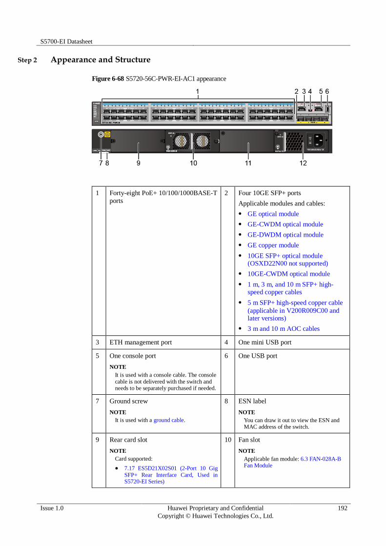
S5700-EI Datasheet
Issue 1.0 Huawei Proprietary and Confidential
Copyright © Huawei Technologies Co., Ltd.
192
Step 2 Appearance and Structure
Figure 6-68 S5720-56C-PWR-EI-AC1 appearance
1 Forty-eight PoE+ 10/100/1000BASE-T
ports
2 Four 10GE SFP+ ports
Applicable modules and cables:
GE optical module
GE-CWDM optical module
GE-DWDM optical module
GE copper module
10GE SFP+ optical module (OSXD22N00 not supported)
10GE-CWDM optical module
1 m, 3 m, and 10 m SFP+ high-speed copper cables
5 m SFP+ high-speed copper cable
(applicable in V200R009C00 and later versions)
3 m and 10 m AOC cables
3 ETH management port 4 One mini USB port
5 One console port
NOTE
It is used with a console cable. The console cable is not delivered with the switch and needs to be separately purchased if needed.
6 One USB port
7 Ground screw
NOTE
It is used with a ground cable.
8 ESN label
NOTE
You can draw it out to view the ESN and MAC address of the switch.
9 Rear card slot
NOTE
Card supported:
7.17 ES5D21X02S01 (2-Port 10 Gig SFP+ Rear Interface Card, Used in S5720-EI Series)
10 Fan slot
NOTE
Applicable fan module: 6.3 FAN-028A-B Fan Module

S5700-EI Datasheet
Issue 1.0 Huawei Proprietary and Confidential
Copyright © Huawei Technologies Co., Ltd.
193
7.18 ES5D21X02T01 (2-Port 10 Gig RJ45 Rear Interface Card, Used in S5720-EI Series)
7.19 ES5D21VST000 (Dedicated Stack Card with 2*QSFP+ Interface, Used in S5720-EI Series)
11 Power module slot 2
NOTE
Applicable power module: 1150 W AC PoE power module
12 Power module slot 1
NOTE
Applicable power module: 1150 W AC PoE power module
Step 3 Port Description
10/100/1000BASE-T port
A 10/100/1000BASE-T Ethernet electrical port sends and receives service data at
10/100/1000 Mbit/s, and must use network cables. Table 3-575 describes the attributes of a
10/100/1000BASE-T Ethernet electrical port.
Table 6-156 Attributes of a 10/100/1000BASE-T Ethernet electrical port
Attribute Description
Connector type RJ45
Standards
compliance
IEEE802.3, IEEE802.3u, IEEE802.3ab
Working mode 10/100/1000 Mbit/s auto-sensing
Full-duplex
Maximum
transmission distance
100 m
10GE SFP+ port
A 10GE SFP+ Ethernet optical port supports auto-sensing to 1000 Mbit/s. It sends and
receives service data at 1000 Mbit/s or 10 Gbit/s. Table 3-576 describes the attributes of a
10GE SFP+ Ethernet optical port.
Table 6-157 Attributes of a 10GE SFP+ port
Attribute Description
Connector type LC/PC
Optical port
attributes
Depend on the optical module used
Standards
compliance
IEEE802.3ae
Working mode GE/10GE auto-sensing

S5700-EI Datasheet
Issue 1.0 Huawei Proprietary and Confidential
Copyright © Huawei Technologies Co., Ltd.
194
Attribute Description
Full-duplex
Console port
The console port is connected to a console for on-site configuration. The port must use a
console cable. The console port is used when a switch is powered on for the first time. For
details about the attributes of a console port, see Table 3-577.
Table 6-158 Attributes of a console port
Attribute Description
Connector type RJ45
Standards
compliance
RS-232
Working mode Duplex Universal Asynchronous Receiver/Transmitter (UART)
Baud rate 9600 bit/s, 19200 bit/s, 38400 bit/s, 57600 bit/s, or 115200 bit/s
Default value: 9600 bit/s
Mini USB port
The mini USB port is connected to a console for on-site configuration. When both the Mini
USB and console port have a cable connected, only the Mini USB port works.
ETH management port
You can connect a switch to a configuration terminal or network management workstation
through the ETH management port to configure the switch locally or remotely. The port must
use a network cable. You can choose to download the software package through the ETH
management port in the BootLoad menu. File transfer through the ETH management port is
faster than transfer through the console port. For details on how to use the ETH management
port, see the Configuration Guide - Basic Configurations. Table 3-578 describes the attributes
of an ETH management port.
Table 6-159 Attributes of an ETH management port
Attribute Description
Connector type RJ45
Standards
compliance
IEEE802.3
Working mode 10/100 Mbit/s auto-sensing
Full duplex
Maximum
transmission distance
100 m
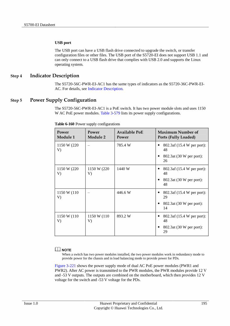
S5700-EI Datasheet
Issue 1.0 Huawei Proprietary and Confidential
Copyright © Huawei Technologies Co., Ltd.
195
USB port
The USB port can have a USB flash drive connected to upgrade the switch, or transfer
configuration files or other files. The USB port of the S5720-EI does not support USB 1.1 and
can only connect to a USB flash drive that complies with USB 2.0 and supports the Linux
operating system.
Step 4 Indicator Description
The S5720-56C-PWR-EI-AC1 has the same types of indicators as the S5720-36C-PWR-EI-
AC. For details, see Indicator Description.
Step 5 Power Supply Configuration
The S5720-56C-PWR-EI-AC1 is a PoE switch. It has two power module slots and uses 1150
W AC PoE power modules. Table 3-579 lists its power supply configurations.
Table 6-160 Power supply configurations
Power Module 1
Power Module 2
Available PoE Power
Maximum Number of Ports (Fully Loaded)
1150 W (220
V)
– 785.4 W 802.3af (15.4 W per port):
48
802.3at (30 W per port): 26
1150 W (220
V)
1150 W (220
V)
1440 W 802.3af (15.4 W per port):
48
802.3at (30 W per port):
48
1150 W (110
V)
– 446.6 W 802.3af (15.4 W per port):
29
802.3at (30 W per port): 14
1150 W (110
V)
1150 W (110
V)
893.2 W 802.3af (15.4 W per port):
48
802.3at (30 W per port): 29
When a switch has two power modules installed, the two power modules work in redundancy mode to provide power for the chassis and in load balancing mode to provide power for PDs.
Figure 3-221 shows the power supply mode of dual AC PoE power modules (PWR1 and
PWR2). After AC power is transmitted to the PWR modules, the PWR modules provide 12 V
and -53 V outputs. The outputs are combined on the motherboard, which then provides 12 V
voltage for the switch and -53 V voltage for the PDs.

S5700-EI Datasheet
Issue 1.0 Huawei Proprietary and Confidential
Copyright © Huawei Technologies Co., Ltd.
196
Figure 6-69 Power supply by dual AC PoE power modules
PWR2
L N
Motherboard
GND12V
PGND
PWR1
L N PGND
-53V RTN
L:
live wire
N:
neutral wire
PGND: protection
ground
GND: 12 V
reference ground
RTN: -53 V
reference ground
Step 6 Heat Dissipation
The S5720-56C-PWR-EI-AC1 uses pluggable fan modules for forced air cooling. Air flows in
from the left and right sides, and exhausts from the rear panel.
Step 7 Technical Specifications
Table 3-580 lists technical specifications of the S5720-56C-PWR-EI-AC1.
Table 6-161 Technical specifications
Item Description
Memory (RAM) 2 GB
Flash 340 MB
Mean time between
failures (MTBF)
51.34 years when no card is configured; 48.63 years when a 2-port
10GE SFP+ interface card is configured; 47.71 years when a 2-port
10GE RJ45 interface card is configured; 47.79 years when a stack card is configured
Mean time to repair 2 hours
S5700-EI Datasheet
Issue 1.0 Huawei Proprietary and Confidential
Copyright © Huawei Technologies Co., Ltd.
197
Item Description
(MTTR)
Availability > 0.99999
Service port surge
protection
Common mode: ±6 kV
Power supply surge
protection
±2 kV in differential mode, ±4 kV in common mode
Dimensions (W
x D x H)
442.0 mm x 420.0 mm x 44.4 mm (17.4 in. x 16.5 in. x 1.74 in.)
When 1150 W power modules are installed, they stretch out from the
chassis. Therefore, the total depth of the switch changes to 507.3 mm (19.97 in.).
Weight Empty: ≤ 8 kg (17.64 lb)
Fully loaded: ≤ 12 kg (26.46 lb)
Stack ports Ports on the 2-port 10GE SFP+ rear interface card
Ports on the 2-port 10GE RJ45 rear interface card
Ports on the 2-port QSFP+ rear stack card
RPS Not supported
PoE Supported
Rated voltage range 100 V AC to 240 V AC, 50/60 Hz
Maximum voltage
range
90 V AC to 264 V AC, 47 Hz to 63 Hz
Maximum power
consumption
(100% throughput, full speed of fans)
Without PoE: 91.6 W
100% PoE loads: 1564.8 W (system power consumption: 124.8 W, PoE: 1440 W)
Operating
temperature
0°C to 45°C (32°F to 113°F) at an altitude of 0-1800 m (0-5096 ft.)
NOTE
When the altitude is 1800-5000 m (5096-16404 ft.), the highest operating temperature reduces by 1°C (1.8°F) every time the altitude increases by 220 m (722 ft.).
Storage
temperature
-40°C to +70°C (-40°F to +158°F)
Noise under normal
temperature (27°C, sound power)
< 61.7 dBA
Relative humidity 5% to 95%, noncondensing
Operating altitude 0-5000 m (0-16404 ft.)
Certification EMC certification
Safety certification
Manufacturing certification

S5700-EI Datasheet
Issue 1.0 Huawei Proprietary and Confidential
Copyright © Huawei Technologies Co., Ltd.
198
6.3.14 S5720-36PC-EI-AC
Step 1 Version Mapping
Table 3-581 lists the mapping between the S5720-36PC-EI-AC chassis and software versions.
Table 6-162 Version mapping
Series Model Software Version
S5720-EI S5720-PC-
EI
S5720-36PC-EI-AC V200R007C00 and later versions
NOTE
This model does not match V200R007C10.
Step 2 Appearance and Structure
Figure 6-70 S5720-36PC-EI-AC appearance
1 Twenty-four 10/100/1000BASE-T
ports
2 Four combo ports (10/100/1000BASE-
T + 100/1000BASE-X)
Modules applicable to the combo optical ports:
FE optical module
GE optical module
GE-CWDM optical module
GE-DWDM optical module
3 Four 1000BASE-X ports
Applicable modules:
GE optical module
GE-CWDM optical module
GE-DWDM optical module
GE copper module (only 1000
4 One mini USB port

S5700-EI Datasheet
Issue 1.0 Huawei Proprietary and Confidential
Copyright © Huawei Technologies Co., Ltd.
199
Mbit/s supported)
5 One console port
NOTE
It is used with a console cable. The console cable is not delivered with the switch and needs to be separately purchased if needed.
6 ETH management port
7 One USB port 8 Ground screw
NOTE
It is used with a ground cable.
9 ESN label
NOTE
You can draw it out to view the ESN and MAC address of the switch.
10 Rear card slot
NOTE
Card supported:
7.17 ES5D21X02S01 (2-Port 10 Gig
SFP+ Rear Interface Card, Used in S5720-EI Series)
7.18 ES5D21X02T01 (2-Port 10 Gig
RJ45 Rear Interface Card, Used in S5720-EI Series)
7.19 ES5D21VST000 (Dedicated Stack
Card with 2*QSFP+ Interface, Used in S5720-EI Series)
11 Fan slot
NOTE
Applicable fan module: 6.3 FAN-028A-B Fan Module
12 Power module slot 2
NOTE
Applicable power modules:
150 W AC power module
150 W DC power module
13 Power module slot 1
NOTE
Applicable power modules:
150 W AC power module
150 W DC power module
- -
Step 3 Port Description
10/100/1000BASE-T port
A 10/100/1000BASE-T Ethernet electrical port sends and receives service data at
10/100/1000 Mbit/s, and must use network cables. Table 3-582 describes the attributes of a
10/100/1000BASE-T Ethernet electrical port.
Table 6-163 Attributes of a 10/100/1000BASE-T Ethernet electrical port
Attribute Description
Connector type RJ45
Standards
compliance
IEEE802.3, IEEE802.3u, IEEE802.3ab
Working mode 10/100/1000 Mbit/s auto-sensing

S5700-EI Datasheet
Issue 1.0 Huawei Proprietary and Confidential
Copyright © Huawei Technologies Co., Ltd.
200
Attribute Description
Full-duplex
Maximum
transmission distance
100 m
Combo port
A combo port refers to a pair of ports consisting of an optical Ethernet port and an electrical
Ethernet port on the panel. Each combo port matches only one internal forwarding port. A
combo port can be configured as an electrical port or an optical port, but only one port can be
active at a time. When one port is active, the other port is shut down.
By default, a combo port works in auto mode, in which the port type is determined as follows:
If the optical port has no optical module installed and the electrical port has no network cable connected, the port type depends on which port is connected first. If the electrical port is connected by a network cable first, the electrical port is used for data switching. If the optical port has an optical module installed first, the optical port is used for data switching.
If the electrical port has a network cable connected and is in Up state, the electrical port is still used for data switching when the optical port has an optical module installed.
If the optical port, no matter in Up or Down state, has an optical module installed, the optical port is still used for data switching when the electrical port has a network cable connected.
If the optical port has an optical module installed and the electrical port has a network cable connected, the optical port is used for data switching after the switch restarts.
You can configure a combo port as an electrical or optical port using the combo-port command.
1000BASE-X port
A 1000BASE-X Ethernet optical port sends and receives service data at 1000 Mbit/s. Table 3-
583 describes the attributes of a 1000BASE-X Ethernet optical port.
Table 6-164 Attributes of a 1000BASE-X Ethernet optical port
Attribute Description
Connector type LC/PC
Optical port
attributes
Depend on the optical module used
Standards
compliance
IEEE802.3z
Working mode 1000 Mbit/s
Full-duplex
Console port
The console port is connected to a console for on-site configuration. The port must use a
console cable. The console port is used when a switch is powered on for the first time. For details about the attributes of a console port, see Table 3-584.
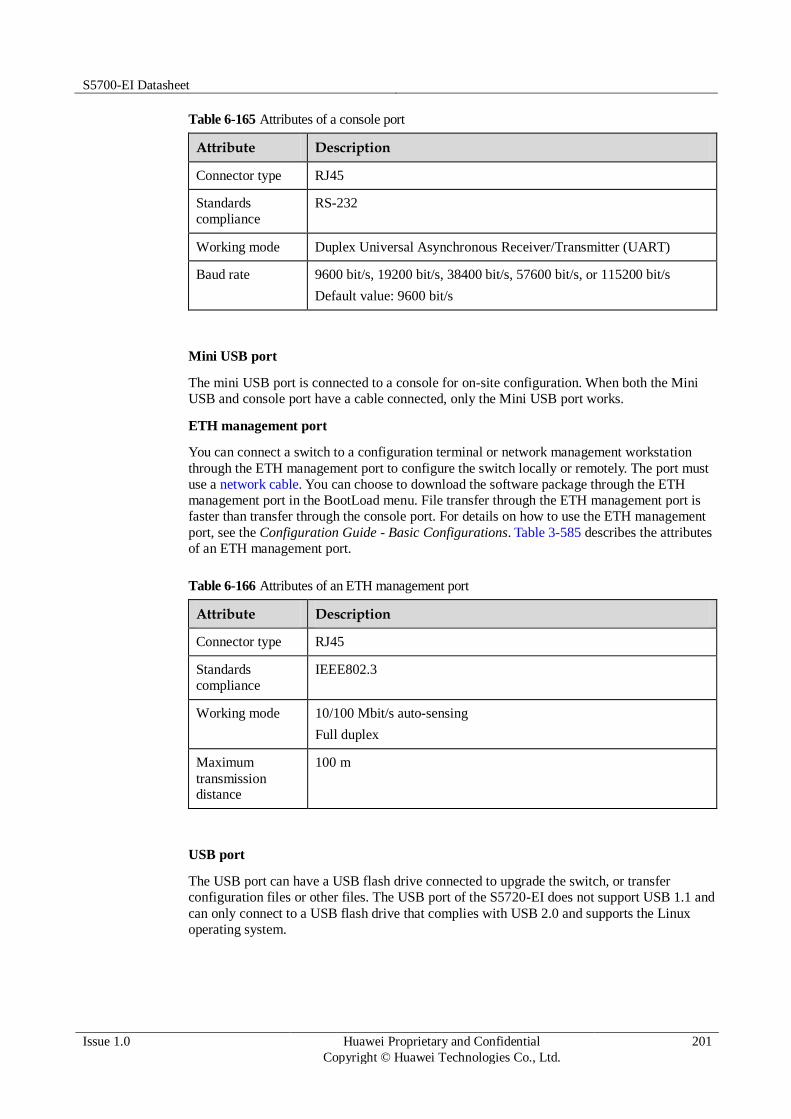
S5700-EI Datasheet
Issue 1.0 Huawei Proprietary and Confidential
Copyright © Huawei Technologies Co., Ltd.
201
Table 6-165 Attributes of a console port
Attribute Description
Connector type RJ45
Standards
compliance
RS-232
Working mode Duplex Universal Asynchronous Receiver/Transmitter (UART)
Baud rate 9600 bit/s, 19200 bit/s, 38400 bit/s, 57600 bit/s, or 115200 bit/s
Default value: 9600 bit/s
Mini USB port
The mini USB port is connected to a console for on-site configuration. When both the Mini
USB and console port have a cable connected, only the Mini USB port works.
ETH management port
You can connect a switch to a configuration terminal or network management workstation
through the ETH management port to configure the switch locally or remotely. The port must
use a network cable. You can choose to download the software package through the ETH
management port in the BootLoad menu. File transfer through the ETH management port is
faster than transfer through the console port. For details on how to use the ETH management
port, see the Configuration Guide - Basic Configurations. Table 3-585 describes the attributes
of an ETH management port.
Table 6-166 Attributes of an ETH management port
Attribute Description
Connector type RJ45
Standards
compliance
IEEE802.3
Working mode 10/100 Mbit/s auto-sensing
Full duplex
Maximum
transmission distance
100 m
USB port
The USB port can have a USB flash drive connected to upgrade the switch, or transfer
configuration files or other files. The USB port of the S5720-EI does not support USB 1.1 and
can only connect to a USB flash drive that complies with USB 2.0 and supports the Linux
operating system.

S5700-EI Datasheet
Issue 1.0 Huawei Proprietary and Confidential
Copyright © Huawei Technologies Co., Ltd.
202
Step 4 Indicator Description
The S5720-36PC-EI-AC has similar indicators to those on the S5720-36C-PWR-EI-AC,
except that the S5720-36PC-EI-AC does not have a PoE mode indicator. For details, see
Indicator Description.
Step 5 Power Supply Configuration
The S5720-36PC-EI-AC uses pluggable power modules. It can be configured with a single
power module or double power modules for 1+1 power redundancy. Pluggable AC and DC
power modules can be used together in the same switch.
Figure 3-223 shows the power supply connections of dual DC power modules. After DC
power is transmitted to the PWR module, the PWR module provides 12 V output voltage, and
the motherboard provides power for the entire device.
Figure 6-71 Power supply connections of dual DC power modules
PWR2
NEG RTN
Motherboard
GND12V
PWR1
NEG RTN
NEG: negative cable RTN: positive cable GND: 12 V reference ground
Figure 3-224 shows the power supply connections of dual non-PoE AC power modules. After
AC power is transmitted to the PWR module, the PWR module provides 12 V output voltage,
and the motherboard provides power for the entire device.
Figure 6-72 Power supply connections of dual non-PoE AC power modules
PWR2
L N
Motherboard
GND12V
PGND
PWR1
L N PGND
L:
Live wire
N:
Neutral wire
PGND: Protective
ground wire
GND: 12 V reference
ground

S5700-EI Datasheet
Issue 1.0 Huawei Proprietary and Confidential
Copyright © Huawei Technologies Co., Ltd.
203
Step 6 Heat Dissipation
The S5720-36PC-EI-AC uses pluggable fan modules for forced air cooling. Air flows in from
the left side, right side, and front panel, and exhausts from the rear panel.
Step 7 Technical Specifications
Table 3-586 lists technical specifications of the S5720-36PC-EI-AC.
Table 6-167 Technical specifications
Item Description
Memory (RAM) 2 GB
Flash 340 MB
Mean time between
failures (MTBF)
80.05 years when no card is configured; 73.65 years when a 2-port
10GE SFP+ interface card is configured; 71.58 years when a 2-port
10GE RJ45 interface card is configured; 71.74 years when a stack card is configured
Mean time to repair
(MTTR)
2 hours
Availability > 0.99999
Service port surge
protection
Common mode: ±6 kV
Power supply surge
protection
Using AC power modules: ±6 kV in differential mode, ±6 kV in
common mode
Using DC power modules: ±1 kV in differential mode, ±2 kV in common mode
Dimensions (W
x D x H)
442.0 mm x 420.0 mm x 44.4 mm (17.4 in. x 16.5 in. x 1.74 in.)
Weight Empty: ≤ 8 kg (17.64 lb)
Fully loaded: ≤ 12 kg (26.46 lb)
Stack ports Ports on the 2-port 10GE SFP+ rear interface card

S5700-EI Datasheet
Issue 1.0 Huawei Proprietary and Confidential
Copyright © Huawei Technologies Co., Ltd.
204
Item Description
Ports on the 2-port 10GE RJ45 rear interface card
Ports on the 2-port QSFP+ rear stack card
RPS Not supported
PoE Not supported
Rated voltage range 100 V AC to 240 V AC, 50/60 Hz
-48 V DC to -60 V DC
Maximum voltage
range
90 V AC to 264 V AC, 47 Hz to 63 Hz
-36 V DC to -72 V DC
Maximum power
consumption
(100% throughput, full speed of fans)
74.6 W
Operating
temperature
0°C to 45°C (32°F to 113°F) at an altitude of 0-1800 m (0-5096 ft.)
NOTE
When the altitude is 1800-5000 m (5096-16404 ft.), the highest operating
temperature reduces by 1°C (1.8°F) every time the altitude increases by 220 m (722 ft.).
Storage
temperature
-40°C to +70°C (-40°F to +158°F)
Noise under normal
temperature (27°C, sound power)
< 51.2 dBA
Relative humidity 5% to 95%, noncondensing
Operating altitude AC power modules configured: 0-5000 m (0-16404 ft.)
DC power modules configured: 0-2000 m (0-6562 ft.)
Certification EMC certification
Safety certification
Manufacturing certification
6.3.15 S5720-56PC-EI-AC
Step 1 Version Mapping
Table 3-587 lists the mapping between the S5720-56PC-EI-AC chassis and software versions.
Table 6-168 Version mapping
Series Model Software Version
S5720-EI S5720-PC- S5720-56PC-EI-AC V200R007C00 and later versions

S5700-EI Datasheet
Issue 1.0 Huawei Proprietary and Confidential
Copyright © Huawei Technologies Co., Ltd.
205
Series Model Software Version
EI NOTE
This model does not match V200R007C10.
Step 2 Appearance and Structure
Figure 6-73 S5720-56PC-EI-AC appearance
1 Forty-eight 10/100/1000BASE-T ports 2 Four 1000BASE-X ports
Applicable modules:
GE optical module
GE-CWDM optical module
GE-DWDM optical module
GE copper module (only 1000 Mbit/s supported)
3 ETH management port 4 One mini USB port
5 One console port
NOTE
It is used with a console cable. The console cable is not delivered with the switch and needs to be separately purchased if needed.
6 One USB port
7 Ground screw
NOTE
It is used with a ground cable.
8 ESN label
NOTE
You can draw it out to view the ESN and MAC address of the switch.
9 Rear card slot
NOTE
Card supported:
7.17 ES5D21X02S01 (2-Port 10 Gig SFP+ Rear Interface Card, Used in S5720-EI Series)
7.18 ES5D21X02T01 (2-Port 10 Gig RJ45 Rear Interface Card, Used in
10 Fan slot
NOTE
Applicable fan module: 6.3 FAN-028A-B Fan Module

S5700-EI Datasheet
Issue 1.0 Huawei Proprietary and Confidential
Copyright © Huawei Technologies Co., Ltd.
206
S5720-EI Series)
7.19 ES5D21VST000 (Dedicated Stack Card with 2*QSFP+ Interface, Used in S5720-EI Series)
11 Power module slot 2
NOTE
Applicable power modules:
150 W AC power module
150 W DC power module
12 Power module slot 1
NOTE
Applicable power modules:
150 W AC power module
150 W DC power module
Step 3 Port Description
10/100/1000BASE-T port
A 10/100/1000BASE-T Ethernet electrical port sends and receives service data at
10/100/1000 Mbit/s, and must use network cables. Table 3-588 describes the attributes of a
10/100/1000BASE-T Ethernet electrical port.
Table 6-169 Attributes of a 10/100/1000BASE-T Ethernet electrical port
Attribute Description
Connector type RJ45
Standards
compliance
IEEE802.3, IEEE802.3u, IEEE802.3ab
Working mode 10/100/1000 Mbit/s auto-sensing
Full-duplex
Maximum
transmission distance
100 m
1000BASE-X port
A 1000BASE-X Ethernet optical port sends and receives service data at 1000 Mbit/s. Table 3-
589 describes the attributes of a 1000BASE-X Ethernet optical port.
Table 6-170 Attributes of a 1000BASE-X Ethernet optical port
Attribute Description
Connector type LC/PC
Optical port attributes
Depend on the optical module used
Standards
compliance
IEEE802.3z
Working mode 1000 Mbit/s
Full-duplex
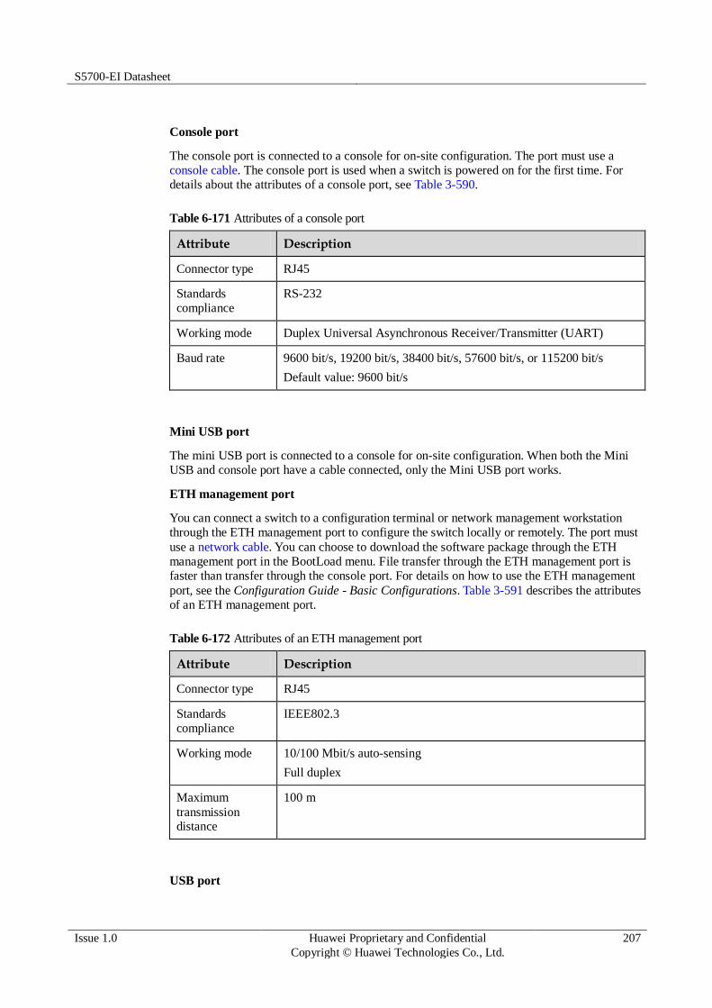
S5700-EI Datasheet
Issue 1.0 Huawei Proprietary and Confidential
Copyright © Huawei Technologies Co., Ltd.
207
Console port
The console port is connected to a console for on-site configuration. The port must use a
console cable. The console port is used when a switch is powered on for the first time. For
details about the attributes of a console port, see Table 3-590.
Table 6-171 Attributes of a console port
Attribute Description
Connector type RJ45
Standards
compliance
RS-232
Working mode Duplex Universal Asynchronous Receiver/Transmitter (UART)
Baud rate 9600 bit/s, 19200 bit/s, 38400 bit/s, 57600 bit/s, or 115200 bit/s
Default value: 9600 bit/s
Mini USB port
The mini USB port is connected to a console for on-site configuration. When both the Mini
USB and console port have a cable connected, only the Mini USB port works.
ETH management port
You can connect a switch to a configuration terminal or network management workstation
through the ETH management port to configure the switch locally or remotely. The port must
use a network cable. You can choose to download the software package through the ETH
management port in the BootLoad menu. File transfer through the ETH management port is
faster than transfer through the console port. For details on how to use the ETH management
port, see the Configuration Guide - Basic Configurations. Table 3-591 describes the attributes
of an ETH management port.
Table 6-172 Attributes of an ETH management port
Attribute Description
Connector type RJ45
Standards
compliance
IEEE802.3
Working mode 10/100 Mbit/s auto-sensing
Full duplex
Maximum
transmission distance
100 m
USB port
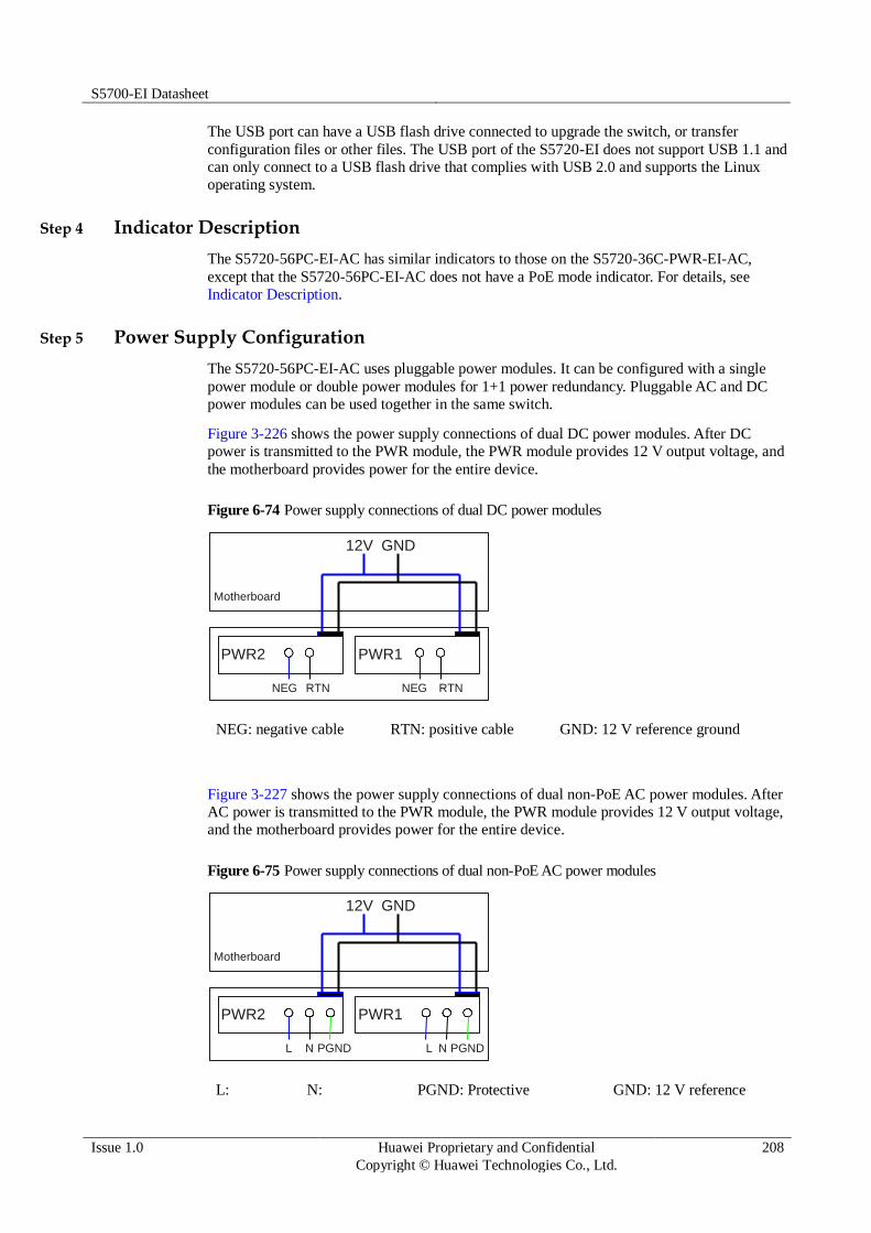
S5700-EI Datasheet
Issue 1.0 Huawei Proprietary and Confidential
Copyright © Huawei Technologies Co., Ltd.
208
The USB port can have a USB flash drive connected to upgrade the switch, or transfer
configuration files or other files. The USB port of the S5720-EI does not support USB 1.1 and
can only connect to a USB flash drive that complies with USB 2.0 and supports the Linux
operating system.
Step 4 Indicator Description
The S5720-56PC-EI-AC has similar indicators to those on the S5720-36C-PWR-EI-AC,
except that the S5720-56PC-EI-AC does not have a PoE mode indicator. For details, see
Indicator Description.
Step 5 Power Supply Configuration
The S5720-56PC-EI-AC uses pluggable power modules. It can be configured with a single
power module or double power modules for 1+1 power redundancy. Pluggable AC and DC
power modules can be used together in the same switch.
Figure 3-226 shows the power supply connections of dual DC power modules. After DC
power is transmitted to the PWR module, the PWR module provides 12 V output voltage, and
the motherboard provides power for the entire device.
Figure 6-74 Power supply connections of dual DC power modules
PWR2
NEG RTN
Motherboard
GND12V
PWR1
NEG RTN
NEG: negative cable RTN: positive cable GND: 12 V reference ground
Figure 3-227 shows the power supply connections of dual non-PoE AC power modules. After
AC power is transmitted to the PWR module, the PWR module provides 12 V output voltage,
and the motherboard provides power for the entire device.
Figure 6-75 Power supply connections of dual non-PoE AC power modules
PWR2
L N
Motherboard
GND12V
PGND
PWR1
L N PGND
L: N: PGND: Protective GND: 12 V reference

S5700-EI Datasheet
Issue 1.0 Huawei Proprietary and Confidential
Copyright © Huawei Technologies Co., Ltd.
209
Live wire Neutral wire ground wire ground
Step 6 Heat Dissipation
The S5720-56PC-EI-AC uses pluggable fan modules for forced air cooling. Air flows in from
the left and right sides, and exhausts from the rear panel.
Step 7 Technical Specifications
Table 3-592 lists technical specifications of the S5720-56PC-EI-AC.
Table 6-173 Technical specifications
Item Description
Memory (RAM) 2 GB
Flash 340 MB
Mean time between
failures (MTBF)
71.18 years when no card is configured; 66.07 years when a 2-port
10GE SFP+ interface card is configured; 66.40 years when a 2-port
10GE RJ45 interface card is configured; 64.53 years when a stack
card is configured
Mean time to repair
(MTTR)
2 hours
Availability > 0.99999
Service port surge
protection
Common mode: ±6 kV
Power supply surge
protection
Using AC power modules: ±6 kV in differential mode, ±6 kV in
common mode
Using DC power modules: ±1 kV in differential mode, ±2 kV in common mode
Dimensions (W
x D x H)
442.0 mm x 420.0 mm x 44.4 mm (17.4 in. x 16.5 in. x 1.74 in.)
Weight Empty: ≤ 8 kg (17.64 lb)

S5700-EI Datasheet
Issue 1.0 Huawei Proprietary and Confidential
Copyright © Huawei Technologies Co., Ltd.
210
Item Description
Fully loaded: ≤ 12 kg (26.46 lb)
Stack ports Ports on the 2-port 10GE SFP+ rear interface card
Ports on the 2-port 10GE RJ45 rear interface card
Ports on the 2-port QSFP+ rear stack card
RPS Not supported
PoE Not supported
Rated voltage range 100 V AC to 240 V AC, 50/60 Hz
-48 V DC to -60 V DC
Maximum voltage
range
90 V AC to 264 V AC, 47 Hz to 63 Hz
-36 V DC to -72 V DC
Maximum power
consumption
(100% throughput, full speed of fans)
85.7 W
Operating
temperature
0°C to 45°C (32°F to 113°F) at an altitude of 0-1800 m (0-5096 ft.)
NOTE
When the altitude is 1800-5000 m (5096-16404 ft.), the highest operating temperature reduces by 1°C (1.8°F) every time the altitude increases by 220 m (722 ft.).
Storage
temperature
-40°C to +70°C (-40°F to +158°F)
Noise under normal
temperature (27°C,
sound power)
< 51.2 dBA
Relative humidity 5% to 95%, noncondensing
Operating altitude AC power modules configured: 0-5000 m (0-16404 ft.)
DC power modules configured: 0-2000 m (0-6562 ft.)
Certification EMC certification
Safety certification
Manufacturing certification
6.3.16 S5720-32X-EI-AC
Step 1 Version Mapping
Table 3-593 lists the mapping between the S5720-32X-EI-AC chassis and software versions.
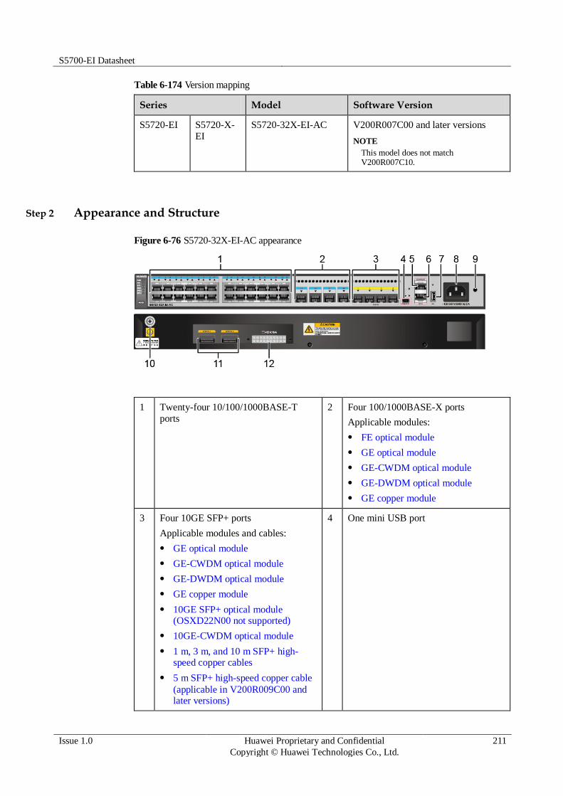
S5700-EI Datasheet
Issue 1.0 Huawei Proprietary and Confidential
Copyright © Huawei Technologies Co., Ltd.
211
Table 6-174 Version mapping
Series Model Software Version
S5720-EI S5720-X-
EI
S5720-32X-EI-AC V200R007C00 and later versions
NOTE
This model does not match V200R007C10.
Step 2 Appearance and Structure
Figure 6-76 S5720-32X-EI-AC appearance
1 Twenty-four 10/100/1000BASE-T
ports
2 Four 100/1000BASE-X ports
Applicable modules:
FE optical module
GE optical module
GE-CWDM optical module
GE-DWDM optical module
GE copper module
3 Four 10GE SFP+ ports
Applicable modules and cables:
GE optical module
GE-CWDM optical module
GE-DWDM optical module
GE copper module
10GE SFP+ optical module (OSXD22N00 not supported)
10GE-CWDM optical module
1 m, 3 m, and 10 m SFP+ high-speed copper cables
5 m SFP+ high-speed copper cable
(applicable in V200R009C00 and later versions)
4 One mini USB port

S5700-EI Datasheet
Issue 1.0 Huawei Proprietary and Confidential
Copyright © Huawei Technologies Co., Ltd.
212
3 m and 10 m AOC cables
5 One console port
NOTE
It is used with a console cable. The console cable is not delivered with the switch and needs to be separately purchased if needed.
6 One ETH management port
7 One USB port 8 AC socket
NOTE
It is used with an AC power cable.
9 Jack for AC terminal locking latch
NOTE
The AC terminal locking latch is not delivered with the switch.
10 Ground screw
NOTE
It is used with a ground cable.
11 Two QSFP+ stack optical ports
Applicable modules and cables:
QSFP+ optical module (only
QSFP-40G-SR4 and QSFP-40G-iSR supported)
1 m, 3 m, and 5 m QSFP+ high-speed copper cables
10 m QSFP+ AOC cable
(applicable in V200R009C00 and
later versions)
12 RPS socket
NOTE
It is used with an RPS cable, which is not hot swappable.
Step 3 Port Description
10/100/1000BASE-T port
A 10/100/1000BASE-T Ethernet electrical port sends and receives service data at
10/100/1000 Mbit/s, and must use network cables. Table 3-594 describes the attributes of a
10/100/1000BASE-T Ethernet electrical port.
Table 6-175 Attributes of a 10/100/1000BASE-T Ethernet electrical port
Attribute Description
Connector type RJ45
Standards
compliance
IEEE802.3, IEEE802.3u, IEEE802.3ab
Working mode 10/100/1000 Mbit/s auto-sensing
Full-duplex
Maximum
transmission distance
100 m
100/1000BASE-X port

S5700-EI Datasheet
Issue 1.0 Huawei Proprietary and Confidential
Copyright © Huawei Technologies Co., Ltd.
213
A 100/1000BASE-X port can send and receive data at 100 Mbit/s or 1000 Mbit/s. Table 3-595
describes the attributes of a 100/1000BASE-X port.
Table 6-176 Attributes of a 100/1000BASE-X port
Attribute Description
Connector type LC/PC
Optical interface
attributes
Depend on the optical module used
Standards
compliance
IEEE802.3z
Working mode 100/1000 Mbit/s auto-sensing
Full-duplex
10GE SFP+ port
A 10GE SFP+ Ethernet optical port supports auto-sensing to 1000 Mbit/s. It sends and
receives service data at 1000 Mbit/s or 10 Gbit/s. Table 3-596 describes the attributes of a
10GE SFP+ Ethernet optical port.
Table 6-177 Attributes of a 10GE SFP+ port
Attribute Description
Connector type LC/PC
Optical port
attributes
Depend on the optical module used
Standards
compliance
IEEE802.3ae
Working mode GE/10GE auto-sensing
Full-duplex
QSFP+ stack optical port
QSFP+ stack optical ports can only be used for stack connection. Table 3-597 describes the
attributes of a QSFP+ stack optical port.
Table 6-178 Attributes of a QSFP+ stack optical port
Attribute Description
Connector type MPO
Optical port
attributes
Depend on the optical module used
Standards IEEE802.3ae

S5700-EI Datasheet
Issue 1.0 Huawei Proprietary and Confidential
Copyright © Huawei Technologies Co., Ltd.
214
Attribute Description
compliance
Working Mode Full-duplex
Console port
The console port is connected to a console for on-site configuration. The port must use a
console cable. The console port is used when a switch is powered on for the first time. For
details about the attributes of a console port, see Table 3-598.
Table 6-179 Attributes of a console port
Attribute Description
Connector type RJ45
Standards
compliance
RS-232
Working mode Duplex Universal Asynchronous Receiver/Transmitter (UART)
Baud rate 9600 bit/s, 19200 bit/s, 38400 bit/s, 57600 bit/s, or 115200 bit/s
Default value: 9600 bit/s
Mini USB port
The mini USB port is connected to a console for on-site configuration. When both the Mini
USB and console port have a cable connected, only the Mini USB port works.
ETH management port
You can connect a switch to a configuration terminal or network management workstation
through the ETH management port to configure the switch locally or remotely. The port must
use a network cable. You can choose to download the software package through the ETH
management port in the BootLoad menu. File transfer through the ETH management port is
faster than transfer through the console port. For details on how to use the ETH management
port, see the Configuration Guide - Basic Configurations. Table 3-599 describes the attributes
of an ETH management port.
Table 6-180 Attributes of an ETH management port
Attribute Description
Connector type RJ45
Standards
compliance
IEEE802.3
Working mode 10/100 Mbit/s auto-sensing
Full duplex
Maximum
transmission
100 m

S5700-EI Datasheet
Issue 1.0 Huawei Proprietary and Confidential
Copyright © Huawei Technologies Co., Ltd.
215
Attribute Description
distance
USB port
The USB port can have a USB flash drive connected to upgrade the switch, or transfer
configuration files or other files. The USB port of the S5720-EI does not support USB 1.1 and
can only connect to a USB flash drive that complies with USB 2.0 and supports the Linux
operating system.
Step 4 Indicator Description
Hold down the mode switch button for 6s and release it to start the web initial login mode. Either of the following situations will occur:
If the switch has no configuration file, the system attempts to enter the web initial login mode. In this mode, the status of mode indicators is as follows:
If the system enters the web initial login mode successfully, all mode indicators turn green and stay on for a maximum of 10 minutes.
If the system fails to enter the initial login mode, all mode indicators fast blink for 10 seconds and then restore to the default status.
If the switch has a configuration file, the system cannot enter the web initial login mode. In this case, all mode indicators fast blink for 10s, and then return to the default states.
Figure 6-77 Indicators on the S5720-32X-EI-AC
The S5720-EI series switches provide a command that can turn on the fault indicators to help field maintenance personnel find a faulty switch.
The SYS indicator and mode indicators (STAT, SPED, STCK, and PoE) are used as fault indicators. When an S5720-EI switch is faulty, you can run the command to turn on the fault indicators. Then the SYS indicator and mode indicators fast blink red to help field maintenance personnel quickly find the fault switch.

S5700-EI Datasheet
Issue 1.0 Huawei Proprietary and Confidential
Copyright © Huawei Technologies Co., Ltd.
216
Table 6-181 Indicator Description
No. Indicator/Button
Color Description
1 PWR: internal
power module
indicator
- Off: The switch is not powered on.
Green Steady on: The power module is
supplying power normally.
Yellow Steady on: The power module has failed,
and the switch is receiving power from a
redundant power supply (RPS).
2 RPS: RPS
indicator
- Off: The RPS is not properly connected
to the switch.
Green Steady on: The RPS is in cold standby
state.
Blinking: The RPS is supplying power to another switch.
Yellow Blinking: The RPS is supplying power to
the local switch, and the built-in power module of the switch has failed.
3 SYS: system
status indicator
- Off: The system is not running.
Green Fast blinking: The system is starting.
Slow blinking: The system is running normally.
Red Steady on: The system does not work
normally after registration, or a fan alarm
or temperature alarm has been generated.
4 STAT: status
indicator
Green Off: The status mode is not selected.
Steady on: The status mode (default
mode) is selected. In this mode,
service port indicators show the port link or activity state.
5 SPED: speed
indicator
Green Off: The speed mode is not selected.
Steady on: The speed mode is
selected. In this mode, service port
indicators show port speeds. After 45
seconds, the service port indicators
automatically restore to the status
mode.
6 STCK: stack
indicator
Green If you are not changing the indicator
mode (default state):
Off: The switch is the standby or
slave switch in a stack or a standalone
switch with the stacking function disabled.
Blinking: The switch is the master

S5700-EI Datasheet
Issue 1.0 Huawei Proprietary and Confidential
Copyright © Huawei Technologies Co., Ltd.
217
No. Indicator/Button
Color Description
switch in a stack or a standalone
switch with the stacking function enabled.
If you are changing the indicator mode:
Off: The stack mode is not selected.
Steady on: The stack mode is
selected. The switch is a standby or
slave switch in a stack, and the service
port indicators show the stack ID of the switch.
Blinking: The switch is the master
switch in a stack or a standalone
switch, and the service port indicators
show the stack ID of the master switch.
After 45 seconds, the service port
indicators automatically restore to the status mode.
7 MODE: mode
switch button
- When you press this button once, the
service port indicators change to the
speed mode and show the speed of
each service port.
When you press this button a second
time, the service port indicators
change to the stack mode and show the stack ID of the local switch.
When you press the button a third
time, the service port indicators
restore to the default mode, and the STAT indicator turns green.
If you do not press the MODE
button within 45 seconds, the service port
indicators restore to the default mode. In
this case, the STAT indicator is steady
green, the SPED indicator is off, and the STCK indicator is off or blinking green.
8 Service port
indicator (one
indicator for
each port)
Meanings of service port indicators vary in different modes.
For details, see Table 3-601.
9 Mini USB
indicator
Green Off: The Mini USB port is disabled,
and the console port is enabled.
Steady on: The Mini USB port is enabled.
When the Mini USB indicator is steady green, the console indicator is off.

S5700-EI Datasheet
Issue 1.0 Huawei Proprietary and Confidential
Copyright © Huawei Technologies Co., Ltd.
218
No. Indicator/Button
Color Description
10 Console
indicator
Green Off: The console port is disabled, and
the Mini USB port is enabled.
Steady on: The console port is
enabled (default state).
When the console indicator is steady green, the Mini USB indicator is off.
11 ETH port
indicator
Green Off: The ETH management port is not
connected.
Steady on: The ETH management port is connected.
Blinking: The port is sending or
receiving data.
12 USB-based
deployment indicator
- Off:
No USB flash drive is connected to
the switch.
The USB port is damaged.
The indicator is damaged.
The USB flash drive does not have
any configuration file and cannot be used for deployment.
The switch has been upgraded using
the USB flash drive and is restarting.
Green Steady on: A USB-based deployment
has been completed.
Blinking: The system is reading data from the USB flash drive.
Yellow Steady on: The switch has copied all the
required files and completed the file
check. The USB flash drive can be
removed from the switch.
Red Blinking: An error has occurred when the
system is executing the configuration file or reading data from the USB flash drive.
Table 6-182 Description of service port indicators in different modes (one indicator for each port)
Display Mode Color Description
Status Green Off: The port is not connected or has
been shut down.
Steady on: The port is connected.
Blinking: The port is sending or

S5700-EI Datasheet
Issue 1.0 Huawei Proprietary and Confidential
Copyright © Huawei Technologies Co., Ltd.
219
Display Mode Color Description
receiving data.
Speed Green Off: The port is not connected or has
been shut down.
Steady on:
10M/100M/1000M port: The port is operating at 10/100 Mbit/s.
1000M/10GE port: The port is operating at 1000 Mbit/s.
Blinking:
10M/100M/1000M port: The port is
operating at 1000 Mbit/s.
1000M/10GE port: The port is operating at 10 Gbit/s.
Stack Green Off: Port indicators do not show the
stack ID of the switch.
If the indicator is steady on, the switch is not a master switch:
If the indicator of a port is steady
on, the number of this port is the stack ID of the switch.
If the first nine port indicators are
steady on, the stack ID of the switch is 0.
If the indicator is blinking, the switch
is a master switch:
If the indicator of a port is
blinking, the number of this port is the stack ID of the switch.
If the first nine port indicators are
blinking, the stack ID of the switch is 0.
Step 5 Power Supply Configuration
The S5720-32X-EI-AC has a built-in power module and does not support pluggable power
modules. It can connect to an RPS1800 power supply for power redundancy.
Figure 3-230 shows the power supply mode of a built-in AC power module. The built-in AC
power module (PWR) receives power from an external power source and provides a 12 V
output to the chassis.

S5700-EI Datasheet
Issue 1.0 Huawei Proprietary and Confidential
Copyright © Huawei Technologies Co., Ltd.
220
Figure 6-78 Power supply mode of a built-in AC power module
Motherboard
GND12V
PWR
L N PGND
L: live wire N: neutral wire PGND: protection ground GND: 12 V reference ground
Step 6 Heat Dissipation
The S5720-32X-EI-AC has built-in fans for forced air cooling. Air flows in from the left side
and front panel, and exhausts from the right side.
Step 7 Technical Specifications
Table 3-602 lists technical specifications of the S5720-32X-EI-AC.
Table 6-183 Technical specifications
Item Description
Memory (RAM) 2 GB
Flash 340 MB
Mean time between
failures (MTBF)
80.32 years
Mean time to repair
(MTTR)
2 hours
Availability > 0.99999
Service port surge
protection
Common mode: ±6 kV
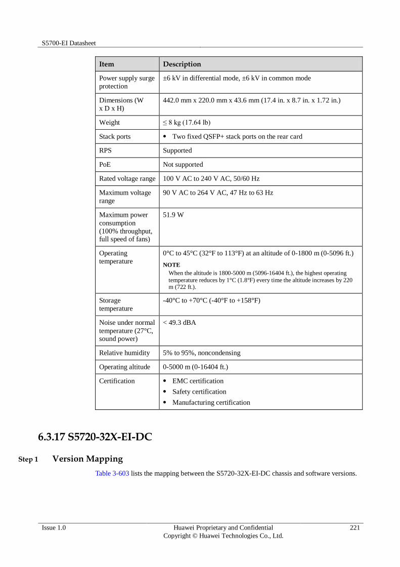
S5700-EI Datasheet
Issue 1.0 Huawei Proprietary and Confidential
Copyright © Huawei Technologies Co., Ltd.
221
Item Description
Power supply surge
protection
±6 kV in differential mode, ±6 kV in common mode
Dimensions (W
x D x H)
442.0 mm x 220.0 mm x 43.6 mm (17.4 in. x 8.7 in. x 1.72 in.)
Weight ≤ 8 kg (17.64 lb)
Stack ports Two fixed QSFP+ stack ports on the rear card
RPS Supported
PoE Not supported
Rated voltage range 100 V AC to 240 V AC, 50/60 Hz
Maximum voltage
range
90 V AC to 264 V AC, 47 Hz to 63 Hz
Maximum power
consumption
(100% throughput, full speed of fans)
51.9 W
Operating
temperature
0°C to 45°C (32°F to 113°F) at an altitude of 0-1800 m (0-5096 ft.)
NOTE
When the altitude is 1800-5000 m (5096-16404 ft.), the highest operating
temperature reduces by 1°C (1.8°F) every time the altitude increases by 220 m (722 ft.).
Storage
temperature
-40°C to +70°C (-40°F to +158°F)
Noise under normal
temperature (27°C, sound power)
< 49.3 dBA
Relative humidity 5% to 95%, noncondensing
Operating altitude 0-5000 m (0-16404 ft.)
Certification EMC certification
Safety certification
Manufacturing certification
6.3.17 S5720-32X-EI-DC
Step 1 Version Mapping
Table 3-603 lists the mapping between the S5720-32X-EI-DC chassis and software versions.

S5700-EI Datasheet
Issue 1.0 Huawei Proprietary and Confidential
Copyright © Huawei Technologies Co., Ltd.
222
Table 6-184 Version mapping
Series Model Software Version
S5720-EI S5720-X-
EI
S5720-32X-EI-DC V200R009C00 and later versions
Step 2 Appearance and Structure
Figure 6-79 S5720-32X-EI-DC appearance
1 Twenty-four 10/100/1000BASE-T
ports
2 Four 100/1000BASE-X ports
Applicable modules:
FE optical module
GE optical module
GE-CWDM optical module
GE-DWDM optical module
GE copper module
3 Four 10GE SFP+ ports
Applicable modules and cables:
GE optical module
GE-CWDM optical module
GE-DWDM optical module
GE copper module
10GE SFP+ optical module (OSXD22N00 not supported)
10GE-CWDM optical module
1 m, 3 m, and 10 m SFP+ high-speed copper cables
5 m SFP+ high-speed copper cable
(applicable in V200R009C00 and later versions)
3 m and 10 m AOC cables
4 One mini USB port

S5700-EI Datasheet
Issue 1.0 Huawei Proprietary and Confidential
Copyright © Huawei Technologies Co., Ltd.
223
5 One console port
NOTE
It is used with a console cable. The console
cable is not delivered with the switch and needs to be separately purchased if needed.
6 One ETH management port
7 One USB port 8 DC power terminal
NOTE
It is used together with a DC Power Cable.
9 Ground screw
NOTE
It is used with a ground cable.
10 Two QSFP+ stack optical ports
Applicable modules and cables:
QSFP+ optical module (only
QSFP-40G-SR4 and QSFP-40G-
iSR supported)
1 m, 3 m, and 5 m QSFP+ high-speed copper cables
10 m QSFP+ AOC cable
(applicable in V200R009C00 and
later versions)
11 RPS socket
NOTE
It is used with an RPS cable, which is not hot swappable.
- -
Step 3 Port Description
10/100/1000BASE-T port
A 10/100/1000BASE-T Ethernet electrical port sends and receives service data at
10/100/1000 Mbit/s, and must use network cables. Table 3-604 describes the attributes of a
10/100/1000BASE-T Ethernet electrical port.
Table 6-185 Attributes of a 10/100/1000BASE-T Ethernet electrical port
Attribute Description
Connector type RJ45
Standards
compliance
IEEE802.3, IEEE802.3u, IEEE802.3ab
Working mode 10/100/1000 Mbit/s auto-sensing
Full-duplex
Maximum
transmission distance
100 m
100/1000BASE-X port

S5700-EI Datasheet
Issue 1.0 Huawei Proprietary and Confidential
Copyright © Huawei Technologies Co., Ltd.
224
A 100/1000BASE-X port can send and receive data at 100 Mbit/s or 1000 Mbit/s. Table 3-605
describes the attributes of a 100/1000BASE-X port.
Table 6-186 Attributes of a 100/1000BASE-X port
Attribute Description
Connector type LC/PC
Optical interface
attributes
Depend on the optical module used
Standards
compliance
IEEE802.3z
Working mode 100/1000 Mbit/s auto-sensing
Full-duplex
10GE SFP+ port
A 10GE SFP+ Ethernet optical port supports auto-sensing to 1000 Mbit/s. It sends and
receives service data at 1000 Mbit/s or 10 Gbit/s. Table 3-606 describes the attributes of a
10GE SFP+ Ethernet optical port.
Table 6-187 Attributes of a 10GE SFP+ port
Attribute Description
Connector type LC/PC
Optical port
attributes
Depend on the optical module used
Standards
compliance
IEEE802.3ae
Working mode GE/10GE auto-sensing
Full-duplex
QSFP+ stack optical port
QSFP+ stack optical ports can only be used for stack connection. Table 3-607 describes the
attributes of a QSFP+ stack optical port.
Table 6-188 Attributes of a QSFP+ stack optical port
Attribute Description
Connector type MPO
Optical port
attributes
Depend on the optical module used
Standards IEEE802.3ae

S5700-EI Datasheet
Issue 1.0 Huawei Proprietary and Confidential
Copyright © Huawei Technologies Co., Ltd.
225
Attribute Description
compliance
Working Mode Full-duplex
Console port
The console port is connected to a console for on-site configuration. The port must use a
console cable. The console port is used when a switch is powered on for the first time. For
details about the attributes of a console port, see Table 3-608.
Table 6-189 Attributes of a console port
Attribute Description
Connector type RJ45
Standards
compliance
RS-232
Working mode Duplex Universal Asynchronous Receiver/Transmitter (UART)
Baud rate 9600 bit/s, 19200 bit/s, 38400 bit/s, 57600 bit/s, or 115200 bit/s
Default value: 9600 bit/s
Mini USB port
The mini USB port is connected to a console for on-site configuration. When both the Mini
USB and console port have a cable connected, only the Mini USB port works.
ETH management port
You can connect a switch to a configuration terminal or network management workstation
through the ETH management port to configure the switch locally or remotely. The port must
use a network cable. You can choose to download the software package through the ETH
management port in the BootLoad menu. File transfer through the ETH management port is
faster than transfer through the console port. For details on how to use the ETH management
port, see the Configuration Guide - Basic Configurations. Table 3-609 describes the attributes
of an ETH management port.
Table 6-190 Attributes of an ETH management port
Attribute Description
Connector type RJ45
Standards
compliance
IEEE802.3
Working mode 10/100 Mbit/s auto-sensing
Full duplex
Maximum
transmission
100 m

S5700-EI Datasheet
Issue 1.0 Huawei Proprietary and Confidential
Copyright © Huawei Technologies Co., Ltd.
226
Attribute Description
distance
USB port
The USB port can have a USB flash drive connected to upgrade the switch, or transfer
configuration files or other files. The USB port of the S5720-EI does not support USB 1.1 and
can only connect to a USB flash drive that complies with USB 2.0 and supports the Linux
operating system.
Step 4 Indicator Description
The S5720-32X-EI-DC have the same types of indicators as the S5720-32X-EI-AC. For
details, see Indicator Description.
Step 5 Power Supply Configuration
The S5720-32X-EI-DC has a built-in power module and does not support pluggable power
modules. It can connect to an RPS1800 power supply for power redundancy.
Figure 3-232 shows the power supply mode of a single DC power module. The built-in DC
power module (PWR) receives DC power from an external power source and provides a 12 V
output to the chassis.
Figure 6-80 Power supply by a single DC power module
Motherboard
GND12V
PWR
NEG RTN
NEG: negative cable RTN: positive cable GND: 12 V reference ground
Step 6 Heat Dissipation
The S5720-32X-EI-DC has built-in fans for forced air cooling. Air flows in from the left side
and front panel, and exhausts from the right side.

S5700-EI Datasheet
Issue 1.0 Huawei Proprietary and Confidential
Copyright © Huawei Technologies Co., Ltd.
227
This figure only shows the airflow direction and does not depict the actual device.
Step 7 Technical Specifications
Table 3-610 lists technical specifications of the S5720-32X-EI-DC.
Table 6-191 Technical specifications
Item Description
Memory (RAM) 2 GB
Flash 340 MB
Mean time between
failures (MTBF)
80.32 years
Mean time to repair
(MTTR)
2 hours
Availability > 0.99999
Service port surge
protection
Common mode: ±6 kV
Power supply surge
protection
±1 kV in differential mode, ±2 kV in common mode
Dimensions (W
x D x H)
442.0 mm x 220.0 mm x 43.6 mm (17.4 in. x 8.7 in. x 1.72 in.)
Weight ≤ 8 kg (17.64 lb)
Stack ports Two fixed QSFP+ stack ports on the rear card
RPS Supported
PoE Not supported
Rated voltage range -48 V DC to -60 V DC
Maximum voltage
range
-36 V DC to -72 V DC
Maximum power
consumption
51.9 W

S5700-EI Datasheet
Issue 1.0 Huawei Proprietary and Confidential
Copyright © Huawei Technologies Co., Ltd.
228
Item Description
(100% throughput, full speed of fans)
Operating
temperature
0°C to 45°C (32°F to 113°F) at an altitude of 0-1800 m (0-5096 ft.)
NOTE
When the altitude is 1800-5000 m (5096-16404 ft.), the highest operating temperature reduces by 1°C (1.8°F) every time the altitude increases by 220 m (722 ft.).
Storage
temperature
-40°C to +70°C (-40°F to +158°F)
Noise under normal
temperature (27°C,
sound power)
< 49.3 dBA
Relative humidity 5% to 95%, noncondensing
Operating altitude 0-2000 m (0-6562 ft.)
Certification EMC certification
Safety certification
Manufacturing certification
6.3.18 S5720-32X-EI-24S-AC
Step 1 Version Mapping
Table 3-611 lists the mapping between the S5720-32X-EI-24S-AC chassis and software
versions.
Table 6-192 Version mapping
Series Model Software Version
S5720-EI S5720-X-
EI
S5720-32X-EI-24S-
AC
V200R007C00 and later versions
NOTE
This model does not match V200R007C10.

S5700-EI Datasheet
Issue 1.0 Huawei Proprietary and Confidential
Copyright © Huawei Technologies Co., Ltd.
229
Step 2 Appearance and Structure
Figure 6-81 S5720-32X-EI-24S-AC appearance
1 Twenty-four 100/1000BASE-X ports
Applicable modules:
FE optical module
GE optical module
GE-CWDM optical module
GE copper module
2 Four 10/100/1000BASE-T ports
3 Four 10GE SFP+ ports
Applicable modules and cables:
GE optical module
GE-CWDM optical module
GE-DWDM optical module
GE copper module
10GE SFP+ optical module
(OSXD22N00 not supported)
10GE-CWDM optical module
1 m, 3 m, and 10 m SFP+ high-speed copper cables
5 m SFP+ high-speed copper cable
(applicable in V200R009C00 and later versions)
3 m and 10 m AOC cables
4 One mini USB port
5 One console port
NOTE
It is used with a console cable. The console cable is not delivered with the switch and needs to be separately purchased if needed.
6 One ETH management port
7 One USB port 8 AC socket
NOTE
It is used with an AC power cable.

S5700-EI Datasheet
Issue 1.0 Huawei Proprietary and Confidential
Copyright © Huawei Technologies Co., Ltd.
230
9 Jack for AC terminal locking latch
NOTE
The AC terminal locking latch is not delivered with the switch.
10 Ground screw
NOTE
It is used with a ground cable.
11 Two QSFP+ stack optical ports
Applicable modules and cables:
QSFP+ optical module (only
QSFP-40G-SR4 and QSFP-40G-
iSR supported)
1 m, 3 m, and 5 m QSFP+ high-speed copper cables
10 m QSFP+ AOC cable
(applicable in V200R009C00 and
later versions)
12 RPS socket
NOTE
It is used with an RPS cable, which is not hot swappable.
Step 3 Port Description
10/100/1000BASE-T port
A 10/100/1000BASE-T Ethernet electrical port sends and receives service data at
10/100/1000 Mbit/s, and must use network cables. Table 3-612 describes the attributes of a
10/100/1000BASE-T Ethernet electrical port.
Table 6-193 Attributes of a 10/100/1000BASE-T Ethernet electrical port
Attribute Description
Connector type RJ45
Standards
compliance
IEEE802.3, IEEE802.3u, IEEE802.3ab
Working mode 10/100/1000 Mbit/s auto-sensing
Full-duplex
Maximum
transmission distance
100 m
100/1000BASE-X port
A 100/1000BASE-X port can send and receive data at 100 Mbit/s or 1000 Mbit/s. Table 3-613
describes the attributes of a 100/1000BASE-X port.
Table 6-194 Attributes of a 100/1000BASE-X port
Attribute Description
Connector type LC/PC
Optical interface attributes
Depend on the optical module used

S5700-EI Datasheet
Issue 1.0 Huawei Proprietary and Confidential
Copyright © Huawei Technologies Co., Ltd.
231
Attribute Description
Standards
compliance
IEEE802.3z
Working mode 100/1000 Mbit/s auto-sensing
Full-duplex
10GE SFP+ port
A 10GE SFP+ Ethernet optical port supports auto-sensing to 1000 Mbit/s. It sends and
receives service data at 1000 Mbit/s or 10 Gbit/s. Table 3-614 describes the attributes of a
10GE SFP+ Ethernet optical port.
Table 6-195 Attributes of a 10GE SFP+ port
Attribute Description
Connector type LC/PC
Optical port
attributes
Depend on the optical module used
Standards
compliance
IEEE802.3ae
Working mode GE/10GE auto-sensing
Full-duplex
QSFP+ stack optical port
QSFP+ stack optical ports can only be used for stack connection. Table 3-615 describes the
attributes of a QSFP+ stack optical port.
Table 6-196 Attributes of a QSFP+ stack optical port
Attribute Description
Connector type MPO
Optical port
attributes
Depend on the optical module used
Standards
compliance
IEEE802.3ae
Working Mode Full-duplex
Console port

S5700-EI Datasheet
Issue 1.0 Huawei Proprietary and Confidential
Copyright © Huawei Technologies Co., Ltd.
232
The console port is connected to a console for on-site configuration. The port must use a
console cable. The console port is used when a switch is powered on for the first time. For
details about the attributes of a console port, see Table 3-616.
Table 6-197 Attributes of a console port
Attribute Description
Connector type RJ45
Standards
compliance
RS-232
Working mode Duplex Universal Asynchronous Receiver/Transmitter (UART)
Baud rate 9600 bit/s, 19200 bit/s, 38400 bit/s, 57600 bit/s, or 115200 bit/s
Default value: 9600 bit/s
Mini USB port
The mini USB port is connected to a console for on-site configuration. When both the Mini
USB and console port have a cable connected, only the Mini USB port works.
ETH management port
You can connect a switch to a configuration terminal or network management workstation
through the ETH management port to configure the switch locally or remotely. The port must
use a network cable. You can choose to download the software package through the ETH
management port in the BootLoad menu. File transfer through the ETH management port is
faster than transfer through the console port. For details on how to use the ETH management
port, see the Configuration Guide - Basic Configurations. Table 3-617 describes the attributes
of an ETH management port.
Table 6-198 Attributes of an ETH management port
Attribute Description
Connector type RJ45
Standards
compliance
IEEE802.3
Working mode 10/100 Mbit/s auto-sensing
Full duplex
Maximum
transmission distance
100 m
USB port
The USB port can have a USB flash drive connected to upgrade the switch, or transfer
configuration files or other files. The USB port of the S5720-EI does not support USB 1.1 and

S5700-EI Datasheet
Issue 1.0 Huawei Proprietary and Confidential
Copyright © Huawei Technologies Co., Ltd.
233
can only connect to a USB flash drive that complies with USB 2.0 and supports the Linux
operating system.
Step 4 Indicator Description
The S5720-32X-EI-24S-AC has 24 downlink optical port indicators, whereas the S5720-32X-
EI-AC has 24 downlink electrical port indicators. Symbols and meanings of other indicators
on the two switch models are the same. For details, see Indicator Description.
Step 5 Power Supply Configuration
The S5720-32X-EI-24S-AC has a built-in power module and does not support pluggable
power modules. It can connect to an RPS1800 power supply for power redundancy.
Figure 3-234 shows the power supply mode of a built-in AC power module. The built-in AC
power module (PWR) receives power from an external power source and provides a 12 V
output to the chassis.
Figure 6-82 Power supply mode of a built-in AC power module
Motherboard
GND12V
PWR
L N PGND
L: live wire N: neutral wire PGND: protection ground GND: 12 V reference ground
Step 6 Heat Dissipation
The S5720-32X-EI-24S-AC has built-in fans for forced air cooling. Air flows in from the left
side and front panel, and exhausts from the right side.
This figure only shows the airflow direction and does not depict the actual device.

S5700-EI Datasheet
Issue 1.0 Huawei Proprietary and Confidential
Copyright © Huawei Technologies Co., Ltd.
234
Step 7 Technical Specifications
Table 3-618 lists technical specifications of the S5720-32X-EI-24S-AC.
Table 6-199 Technical specifications
Item Description
Memory (RAM) 2 GB
Flash 340 MB
Mean time between
failures (MTBF)
82.54 years
Mean time to repair
(MTTR)
2 hours
Availability > 0.99999
Service port surge
protection
Common mode: ±6 kV
Power supply surge
protection
±6 kV in differential mode, ±6 kV in common mode
Dimensions (W
x D x H)
442.0 mm x 220.0 mm x 43.6 mm (17.4 in. x 8.7 in. x 1.72 in.)
Weight ≤ 8 kg (17.64 lb)
Stack ports Two fixed QSFP+ stack ports on the rear card
RPS Supported
PoE Not supported
Rated voltage range 100 V AC to 240 V AC, 50/60 Hz
Maximum voltage
range
90 V AC to 264 V AC, 47 Hz to 63 Hz
Maximum power
consumption
(100% throughput, full speed of fans)
58.9 W
Operating
temperature
0°C to 45°C (32°F to 113°F) at an altitude of 0-1800 m (0-5096 ft.)
NOTE
When the altitude is 1800-5000 m (5096-16404 ft.), the highest operating temperature reduces by 1°C (1.8°F) every time the altitude increases by 220 m (722 ft.).
Storage
temperature
-40°C to +70°C (-40°F to +158°F)
Noise under normal
temperature (27°C, sound power)
< 49.3 dBA

S5700-EI Datasheet
Issue 1.0 Huawei Proprietary and Confidential
Copyright © Huawei Technologies Co., Ltd.
235
Item Description
Relative humidity 5% to 95%, noncondensing
Operating altitude 0-5000 m (0-16404 ft.)
Certification EMC certification
Safety certification
Manufacturing certification
6.3.19 S5720-32X-EI-24S-DC
Step 1 Version Mapping
Table 3-619 lists the mapping between the S5720-32X-EI-24S-DC chassis and software
versions.
Table 6-200 Version mapping
Series Model Software Version
S5720-EI S5720-X-
EI
S5720-32X-EI-24S-
DC
V200R009C00 and later versions
Step 2 Appearance and Structure
Figure 6-83 S5720-32X-EI-24S-DC appearance
1 Twenty-four 100/1000BASE-X ports
Applicable modules:
FE optical module
GE optical module
GE-CWDM optical module
GE copper module
2 Four 10/100/1000BASE-T ports

S5700-EI Datasheet
Issue 1.0 Huawei Proprietary and Confidential
Copyright © Huawei Technologies Co., Ltd.
236
3 Four 10GE SFP+ ports
Applicable modules and cables:
GE optical module
GE-CWDM optical module
GE-DWDM optical module
GE copper module
10GE SFP+ optical module (OSXD22N00 not supported)
10GE-CWDM optical module
1 m, 3 m, and 10 m SFP+ high-
speed copper cables
5 m SFP+ high-speed copper cable
(applicable in V200R009C00 and later versions)
3 m and 10 m AOC cables
4 One mini USB port
5 One console port
NOTE
It is used with a console cable. The console cable is not delivered with the switch and needs to be separately purchased if needed.
6 One ETH management port
7 One USB port 8 DC power terminal
NOTE
It is used together with a DC Power Cable.
9 Ground screw
NOTE
It is used with a ground cable.
10 Two QSFP+ stack optical ports
Applicable modules and cables:
QSFP+ optical module (only
QSFP-40G-SR4 and QSFP-40G-
iSR supported)
1 m, 3 m, and 5 m QSFP+ high-
speed copper cables
10 m QSFP+ AOC cable
(applicable in V200R009C00 and later versions)
11 RPS socket
NOTE
It is used with an RPS cable, which is not hot swappable.
- -
Step 3 Port Description
10/100/1000BASE-T port
A 10/100/1000BASE-T Ethernet electrical port sends and receives service data at
10/100/1000 Mbit/s, and must use network cables. Table 3-620 describes the attributes of a
10/100/1000BASE-T Ethernet electrical port.

S5700-EI Datasheet
Issue 1.0 Huawei Proprietary and Confidential
Copyright © Huawei Technologies Co., Ltd.
237
Table 6-201 Attributes of a 10/100/1000BASE-T Ethernet electrical port
Attribute Description
Connector type RJ45
Standards
compliance
IEEE802.3, IEEE802.3u, IEEE802.3ab
Working mode 10/100/1000 Mbit/s auto-sensing
Full-duplex
Maximum
transmission
distance
100 m
100/1000BASE-X port
A 100/1000BASE-X port can send and receive data at 100 Mbit/s or 1000 Mbit/s. Table 3-621
describes the attributes of a 100/1000BASE-X port.
Table 6-202 Attributes of a 100/1000BASE-X port
Attribute Description
Connector type LC/PC
Optical interface
attributes
Depend on the optical module used
Standards
compliance
IEEE802.3z
Working mode 100/1000 Mbit/s auto-sensing
Full-duplex
10GE SFP+ port
A 10GE SFP+ Ethernet optical port supports auto-sensing to 1000 Mbit/s. It sends and
receives service data at 1000 Mbit/s or 10 Gbit/s. Table 3-622 describes the attributes of a
10GE SFP+ Ethernet optical port.
Table 6-203 Attributes of a 10GE SFP+ port
Attribute Description
Connector type LC/PC
Optical port
attributes
Depend on the optical module used
Standards
compliance
IEEE802.3ae
Working mode GE/10GE auto-sensing

S5700-EI Datasheet
Issue 1.0 Huawei Proprietary and Confidential
Copyright © Huawei Technologies Co., Ltd.
238
Attribute Description
Full-duplex
QSFP+ stack optical port
QSFP+ stack optical ports can only be used for stack connection. Table 3-623 describes the
attributes of a QSFP+ stack optical port.
Table 6-204 Attributes of a QSFP+ stack optical port
Attribute Description
Connector type MPO
Optical port
attributes
Depend on the optical module used
Standards
compliance
IEEE802.3ae
Working Mode Full-duplex
Console port
The console port is connected to a console for on-site configuration. The port must use a
console cable. The console port is used when a switch is powered on for the first time. For
details about the attributes of a console port, see Table 3-624.
Table 6-205 Attributes of a console port
Attribute Description
Connector type RJ45
Standards
compliance
RS-232
Working mode Duplex Universal Asynchronous Receiver/Transmitter (UART)
Baud rate 9600 bit/s, 19200 bit/s, 38400 bit/s, 57600 bit/s, or 115200 bit/s
Default value: 9600 bit/s
Mini USB port
The mini USB port is connected to a console for on-site configuration. When both the Mini
USB and console port have a cable connected, only the Mini USB port works.
ETH management port
You can connect a switch to a configuration terminal or network management workstation
through the ETH management port to configure the switch locally or remotely. The port must use a network cable. You can choose to download the software package through the ETH
management port in the BootLoad menu. File transfer through the ETH management port is

S5700-EI Datasheet
Issue 1.0 Huawei Proprietary and Confidential
Copyright © Huawei Technologies Co., Ltd.
239
faster than transfer through the console port. For details on how to use the ETH management
port, see the Configuration Guide - Basic Configurations. Table 3-625 describes the attributes
of an ETH management port.
Table 6-206 Attributes of an ETH management port
Attribute Description
Connector type RJ45
Standards
compliance
IEEE802.3
Working mode 10/100 Mbit/s auto-sensing
Full duplex
Maximum
transmission distance
100 m
USB port
The USB port can have a USB flash drive connected to upgrade the switch, or transfer
configuration files or other files. The USB port of the S5720-EI does not support USB 1.1 and
can only connect to a USB flash drive that complies with USB 2.0 and supports the Linux
operating system.
Step 4 Indicator Description
The S5720-32X-EI-24S-DC has 24 downlink optical port indicators, whereas the S5720-32X-
EI-AC has 24 downlink electrical port indicators. Symbols and meanings of other indicators
on the two switch models are the same. For details, see Indicator Description.
Step 5 Power Supply Configuration
The S5720-32X-EI-24S-DC has a built-in power module and does not support pluggable
power modules. It can connect to an RPS1800 power supply for power redundancy.
Figure 3-236 shows the power supply mode of a single DC power module. The built-in DC
power module (PWR) receives DC power from an external power source and provides a 12 V
output to the chassis.
Figure 6-84 Power supply by a single DC power module
Motherboard
GND12V
PWR
NEG RTN

S5700-EI Datasheet
Issue 1.0 Huawei Proprietary and Confidential
Copyright © Huawei Technologies Co., Ltd.
240
NEG: negative cable RTN: positive cable GND: 12 V reference ground
Step 6 Heat Dissipation
The S5720-32X-EI-24S-DC has built-in fans for forced air cooling. Air flows in from the left
side and front panel, and exhausts from the right side.
This figure only shows the airflow direction and does not depict the actual device.
Step 7 Technical Specifications
Table 3-626 lists technical specifications of the S5720-32X-EI-24S-DC.
Table 6-207 Technical specifications
Item Description
Memory (RAM) 2 GB
Flash 340 MB
Mean time between
failures (MTBF)
82.54 years
Mean time to repair
(MTTR)
2 hours
Availability > 0.99999
Service port surge
protection
Common mode: ±6 kV
Power supply surge
protection
±1 kV in differential mode, ±2 kV in common mode
Dimensions (W
x D x H)
442.0 mm x 220.0 mm x 43.6 mm (17.4 in. x 8.7 in. x 1.72 in.)
Weight ≤ 8 kg (17.64 lb)
Stack ports Two fixed QSFP+ stack ports on the rear card
RPS Supported

S5700-EI Datasheet
Issue 1.0 Huawei Proprietary and Confidential
Copyright © Huawei Technologies Co., Ltd.
241
Item Description
PoE Not supported
Rated voltage range -48 V DC to -60 V DC
Maximum voltage
range
-36 V DC to -72 V DC
Maximum power
consumption
(100% throughput, full speed of fans)
58.9 W
Operating
temperature
0°C to 45°C (32°F to 113°F) at an altitude of 0-1800 m (0-5096 ft.)
NOTE
When the altitude is 1800-5000 m (5096-16404 ft.), the highest operating temperature reduces by 1°C (1.8°F) every time the altitude increases by 220 m (722 ft.).
Storage
temperature
-40°C to +70°C (-40°F to +158°F)
Noise under normal
temperature (27°C, sound power)
< 49.3 dBA
Relative humidity 5% to 95%, noncondensing
Operating altitude 0-2000 m (0-6562 ft.)
Certification EMC certification
Safety certification
Manufacturing certification
6.3.20 S5720-50X-EI-AC
Step 1 Version Mapping
Table 3-627 lists the mapping between the S5720-50X-EI-AC chassis and software versions.
Table 6-208 Version mapping
Series Model Software Version
S5720-EI S5720-X-
EI
S5720-50X-EI-AC V200R007C00 and later versions
NOTE
This model does not match V200R007C10.

S5700-EI Datasheet
Issue 1.0 Huawei Proprietary and Confidential
Copyright © Huawei Technologies Co., Ltd.
242
Step 2 Appearance and Structure
Figure 6-85 S5720-50X-EI-AC appearance
1 One console port
NOTE
It is used with a console cable. The console cable is not delivered with the switch and needs to be separately purchased if needed.
2 One USB port
3 Forty-six 10/100/1000BASE-T ports 4 Four 10GE SFP+ ports
Applicable modules and cables:
GE optical module
GE-CWDM optical module
GE-DWDM optical module
GE copper module
10GE SFP+ optical module (OSXD22N00 not supported)
10GE-CWDM optical module
1 m, 3 m, and 10 m SFP+ high-speed copper cables
5 m SFP+ high-speed copper cable
(applicable in V200R009C00 and later versions)
3 m and 10 m AOC cables
5 AC socket
NOTE
It is used with an AC power cable.
6 Ground screw
NOTE
It is used with a ground cable.
7 Two QSFP+ stack optical ports
Applicable modules and cables:
QSFP+ optical module (only QSFP-
40G-SR4 and QSFP-40G-iSR supported)
1 m, 3 m, and 5 m QSFP+ high-speed copper cables
10 m QSFP+ AOC cable (applicable
8 RPS socket
NOTE
It is used with an RPS cable, which is not hot swappable.

S5700-EI Datasheet
Issue 1.0 Huawei Proprietary and Confidential
Copyright © Huawei Technologies Co., Ltd.
243
in V200R009C00 and later versions)
Step 3 Port Description
10/100/1000BASE-T port
A 10/100/1000BASE-T Ethernet electrical port sends and receives service data at
10/100/1000 Mbit/s, and must use network cables. Table 3-628 describes the attributes of a
10/100/1000BASE-T Ethernet electrical port.
Table 6-209 Attributes of a 10/100/1000BASE-T Ethernet electrical port
Attribute Description
Connector type RJ45
Standards
compliance
IEEE802.3, IEEE802.3u, IEEE802.3ab
Working mode 10/100/1000 Mbit/s auto-sensing
Full-duplex
Maximum
transmission distance
100 m
10GE SFP+ port
A 10GE SFP+ Ethernet optical port supports auto-sensing to 1000 Mbit/s. It sends and
receives service data at 1000 Mbit/s or 10 Gbit/s. Table 3-629 describes the attributes of a
10GE SFP+ Ethernet optical port.
Table 6-210 Attributes of a 10GE SFP+ port
Attribute Description
Connector type LC/PC
Optical port attributes
Depend on the optical module used
Standards
compliance
IEEE802.3ae
Working mode GE/10GE auto-sensing
Full-duplex
QSFP+ stack optical port
QSFP+ stack optical ports can only be used for stack connection. Table 3-630 describes the
attributes of a QSFP+ stack optical port.
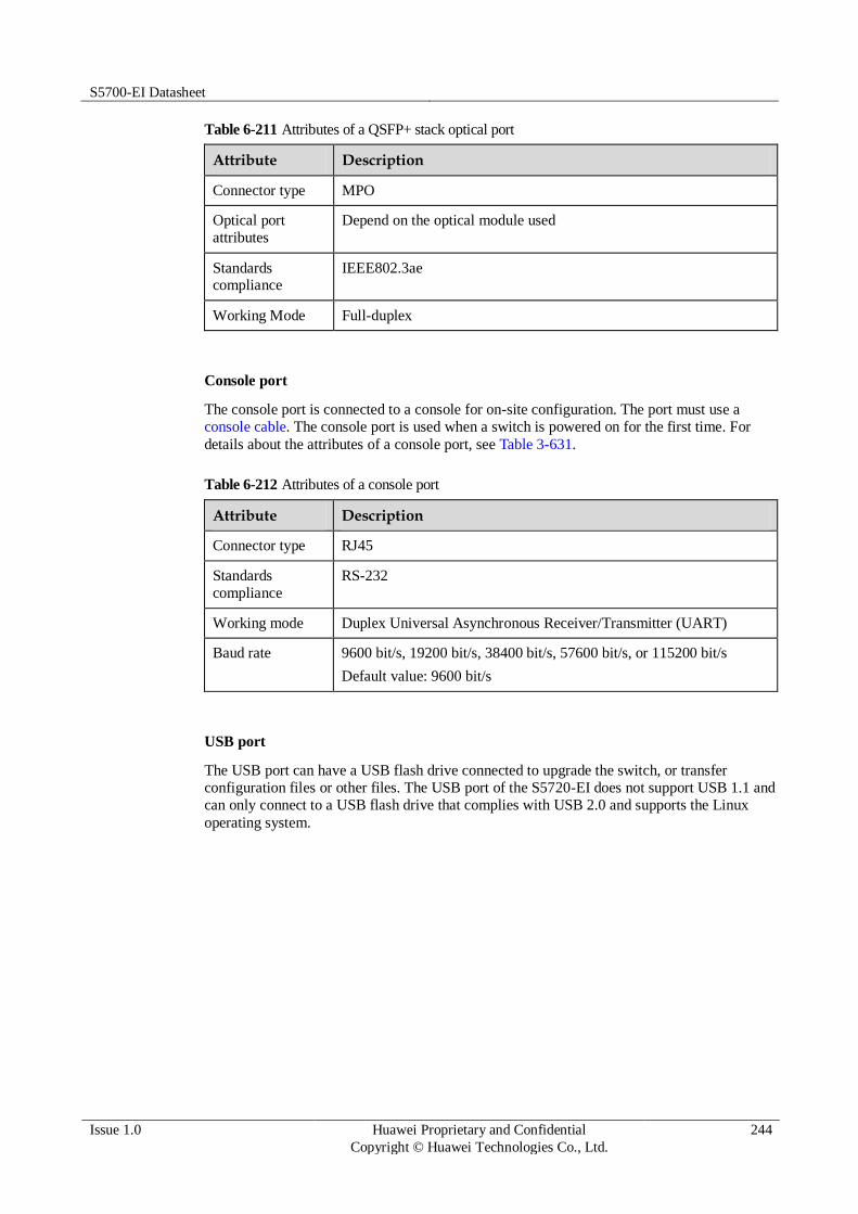
S5700-EI Datasheet
Issue 1.0 Huawei Proprietary and Confidential
Copyright © Huawei Technologies Co., Ltd.
244
Table 6-211 Attributes of a QSFP+ stack optical port
Attribute Description
Connector type MPO
Optical port
attributes
Depend on the optical module used
Standards compliance
IEEE802.3ae
Working Mode Full-duplex
Console port
The console port is connected to a console for on-site configuration. The port must use a
console cable. The console port is used when a switch is powered on for the first time. For
details about the attributes of a console port, see Table 3-631.
Table 6-212 Attributes of a console port
Attribute Description
Connector type RJ45
Standards
compliance
RS-232
Working mode Duplex Universal Asynchronous Receiver/Transmitter (UART)
Baud rate 9600 bit/s, 19200 bit/s, 38400 bit/s, 57600 bit/s, or 115200 bit/s
Default value: 9600 bit/s
USB port
The USB port can have a USB flash drive connected to upgrade the switch, or transfer
configuration files or other files. The USB port of the S5720-EI does not support USB 1.1 and
can only connect to a USB flash drive that complies with USB 2.0 and supports the Linux
operating system.

S5700-EI Datasheet
Issue 1.0 Huawei Proprietary and Confidential
Copyright © Huawei Technologies Co., Ltd.
245
Step 4 Indicator Description
Figure 6-86 Indicators on the S5720-50X-EI-AC
Table 6-213 Description of indicators on the switch
No. Indicator/Button
Color Description
1 SYS: system
status indicator
- Off: The system is not running.
Green Fast blinking: The system is starting.
Slow blinking: The system is running normally.
Red Steady on: The system does not work
normally after registration, or a fan alarm or temperature alarm has been generated.
2 USB-based
deployment
indicator
- Off:
No USB flash drive is connected to the switch.
The USB port is damaged.
The indicator is damaged.
The USB flash drive does not have
any configuration file and cannot be used for deployment.
The switch has been upgraded using the USB flash drive and is restarting.
Green Steady on: A USB-based deployment
has been completed.
Blinking: The system is reading data
from the USB flash drive.
Yellow Steady on: The switch has copied all the
required files and completed the file
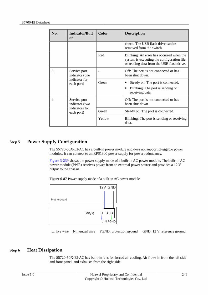
S5700-EI Datasheet
Issue 1.0 Huawei Proprietary and Confidential
Copyright © Huawei Technologies Co., Ltd.
246
No. Indicator/Button
Color Description
check. The USB flash drive can be
removed from the switch.
Red Blinking: An error has occurred when the
system is executing the configuration file or reading data from the USB flash drive.
3 Service port
indicator (one
indicator for each port)
- Off: The port is not connected or has
been shut down.
Green Steady on: The port is connected.
Blinking: The port is sending or receiving data.
4 Service port
indicator (two
indicators for each port)
- Off: The port is not connected or has
been shut down.
Green Steady on: The port is connected.
Yellow Blinking: The port is sending or receiving
data.
Step 5 Power Supply Configuration
The S5720-50X-EI-AC has a built-in power module and does not support pluggable power
modules. It can connect to an RPS1800 power supply for power redundancy.
Figure 3-239 shows the power supply mode of a built-in AC power module. The built-in AC
power module (PWR) receives power from an external power source and provides a 12 V
output to the chassis.
Figure 6-87 Power supply mode of a built-in AC power module
Motherboard
GND12V
PWR
L N PGND
L: live wire N: neutral wire PGND: protection ground GND: 12 V reference ground
Step 6 Heat Dissipation
The S5720-50X-EI-AC has built-in fans for forced air cooling. Air flows in from the left side
and front panel, and exhausts from the right side.

S5700-EI Datasheet
Issue 1.0 Huawei Proprietary and Confidential
Copyright © Huawei Technologies Co., Ltd.
247
This figure only shows the airflow direction and does not depict the actual device.
Step 7 Technical Specifications
Table 3-633 lists technical specifications of the S5720-50X-EI-AC.
Table 6-214 Technical specifications
Item Description
Memory (RAM) 2 GB
Flash 340 MB
Mean time between
failures (MTBF)
74.31 years
Mean time to repair
(MTTR)
2 hours
Availability > 0.99999
Service port surge
protection
Common mode: ±6 kV
Power supply surge
protection
±6 kV in differential mode, ±6 kV in common mode
Dimensions (W
x D x H)
442.0 mm x 220.0 mm x 43.6 mm (17.4 in. x 8.7 in. x 1.72 in.)
Weight ≤ 8 kg (17.64 lb)
Stack ports Two fixed QSFP+ stack ports on the rear card
RPS Supported
PoE Not supported
Rated voltage range 100 V AC to 240 V AC, 50/60 Hz
Maximum voltage
range
90 V AC to 264 V AC, 47 Hz to 63 Hz
Maximum power
consumption
55.3 W

S5700-EI Datasheet
Issue 1.0 Huawei Proprietary and Confidential
Copyright © Huawei Technologies Co., Ltd.
248
Item Description
(100% throughput, full speed of fans)
Operating
temperature
0°C to 45°C (32°F to 113°F) at an altitude of 0-1800 m (0-5096 ft.)
NOTE
When the altitude is 1800-5000 m (5096-16404 ft.), the highest operating temperature reduces by 1°C (1.8°F) every time the altitude increases by 220 m (722 ft.).
Storage
temperature
-40°C to +70°C (-40°F to +158°F)
Noise under normal
temperature (27°C,
sound power)
< 49.3 dBA
Relative humidity 5% to 95%, noncondensing
Operating altitude 0-5000 m (0-16404 ft.)
Certification EMC certification
Safety certification
Manufacturing certification
6.3.21 S5720-50X-EI-DC
Step 1 Version Mapping
Table 3-634 lists the mapping between the S5720-50X-EI-DC chassis and software versions.
Table 6-215 Version mapping
Series Model Software Version
S5720-EI S5720-X-
EI
S5720-50X-EI-DC V200R009C00 and later versions

S5700-EI Datasheet
Issue 1.0 Huawei Proprietary and Confidential
Copyright © Huawei Technologies Co., Ltd.
249
Step 2 Appearance and Structure
Figure 6-88 S5720-50X-EI-DC appearance
1 One console port
NOTE
It is used with a console cable. The console cable is not delivered with the switch and needs to be separately purchased if needed.
2 One USB port
3 Forty-six 10/100/1000BASE-T ports 4 Four 10GE SFP+ ports
Applicable modules and cables:
GE optical module
GE-CWDM optical module
GE-DWDM optical module
GE copper module
10GE SFP+ optical module (OSXD22N00 not supported)
10GE-CWDM optical module
1 m, 3 m, and 10 m SFP+ high-speed copper cables
5 m SFP+ high-speed copper cable
(applicable in V200R009C00 and later versions)
3 m and 10 m AOC cables
5 DC power terminal
NOTE
It is used together with a DC Power Cable.
6 Ground screw
NOTE
It is used with a ground cable.
7 Two QSFP+ stack optical ports
Applicable modules and cables:
QSFP+ optical module (only QSFP-
40G-SR4 and QSFP-40G-iSR supported)
1 m, 3 m, and 5 m QSFP+ high-speed copper cables
10 m QSFP+ AOC cable (applicable
8 RPS socket
NOTE
It is used with an RPS cable, which is not hot swappable.

S5700-EI Datasheet
Issue 1.0 Huawei Proprietary and Confidential
Copyright © Huawei Technologies Co., Ltd.
250
in V200R009C00 and later versions)
Step 3 Port Description
10/100/1000BASE-T port
A 10/100/1000BASE-T Ethernet electrical port sends and receives service data at
10/100/1000 Mbit/s, and must use network cables. Table 3-635 describes the attributes of a
10/100/1000BASE-T Ethernet electrical port.
Table 6-216 Attributes of a 10/100/1000BASE-T Ethernet electrical port
Attribute Description
Connector type RJ45
Standards
compliance
IEEE802.3, IEEE802.3u, IEEE802.3ab
Working mode 10/100/1000 Mbit/s auto-sensing
Full-duplex
Maximum
transmission distance
100 m
10GE SFP+ port
A 10GE SFP+ Ethernet optical port supports auto-sensing to 1000 Mbit/s. It sends and
receives service data at 1000 Mbit/s or 10 Gbit/s. Table 3-636 describes the attributes of a
10GE SFP+ Ethernet optical port.
Table 6-217 Attributes of a 10GE SFP+ port
Attribute Description
Connector type LC/PC
Optical port attributes
Depend on the optical module used
Standards
compliance
IEEE802.3ae
Working mode GE/10GE auto-sensing
Full-duplex
QSFP+ stack optical port
QSFP+ stack optical ports can only be used for stack connection. Table 3-637 describes the
attributes of a QSFP+ stack optical port.

S5700-EI Datasheet
Issue 1.0 Huawei Proprietary and Confidential
Copyright © Huawei Technologies Co., Ltd.
251
Table 6-218 Attributes of a QSFP+ stack optical port
Attribute Description
Connector type MPO
Optical port
attributes
Depend on the optical module used
Standards compliance
IEEE802.3ae
Working Mode Full-duplex
Console port
The console port is connected to a console for on-site configuration. The port must use a
console cable. The console port is used when a switch is powered on for the first time. For
details about the attributes of a console port, see Table 3-638.
Table 6-219 Attributes of a console port
Attribute Description
Connector type RJ45
Standards
compliance
RS-232
Working mode Duplex Universal Asynchronous Receiver/Transmitter (UART)
Baud rate 9600 bit/s, 19200 bit/s, 38400 bit/s, 57600 bit/s, or 115200 bit/s
Default value: 9600 bit/s
USB port
The USB port can have a USB flash drive connected to upgrade the switch, or transfer
configuration files or other files. The USB port of the S5720-EI does not support USB 1.1 and
can only connect to a USB flash drive that complies with USB 2.0 and supports the Linux
operating system.
Step 4 Indicator Description
The S5720-50X-EI-DC have the same types of indicators as the S5720-50X-EI-AC. For
details, see Indicator Description.
Step 5 Power Supply Configuration
The S5720-50X-EI-DC has a built-in power module and does not support pluggable power
modules. It can connect to an RPS1800 power supply for power redundancy.
Figure 3-241 shows the power supply mode of a single DC power module. The built-in DC
power module (PWR) receives DC power from an external power source and provides a 12 V
output to the chassis.

S5700-EI Datasheet
Issue 1.0 Huawei Proprietary and Confidential
Copyright © Huawei Technologies Co., Ltd.
252
Figure 6-89 Power supply by a single DC power module
Motherboard
GND12V
PWR
NEG RTN
NEG: negative cable RTN: positive cable GND: 12 V reference ground
Step 6 Heat Dissipation
The S5720-50X-EI-DC has built-in fans for forced air cooling. Air flows in from the left side
and front panel, and exhausts from the right side.
This figure only shows the airflow direction and does not depict the actual device.
Step 7 Technical Specifications
Table 3-639 lists technical specifications of the S5720-50X-EI-DC.
Table 6-220 Technical specifications
Item Description
Memory (RAM) 2 GB
Flash 340 MB
Mean time between
failures (MTBF)
74.31 years
Mean time to repair
(MTTR)
2
Availability > 0.99999
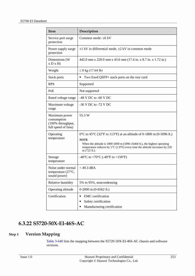
S5700-EI Datasheet
Issue 1.0 Huawei Proprietary and Confidential
Copyright © Huawei Technologies Co., Ltd.
253
Item Description
Service port surge
protection
Common mode: ±6 kV
Power supply surge
protection
±1 kV in differential mode, ±2 kV in common mode
Dimensions (W
x D x H)
442.0 mm x 220.0 mm x 43.6 mm (17.4 in. x 8.7 in. x 1.72 in.)
Weight ≤ 8 kg (17.64 lb)
Stack ports Two fixed QSFP+ stack ports on the rear card
RPS Supported
PoE Not supported
Rated voltage range -48 V DC to -60 V DC
Maximum voltage
range
-36 V DC to -72 V DC
Maximum power
consumption
(100% throughput, full speed of fans)
55.3 W
Operating
temperature
0°C to 45°C (32°F to 113°F) at an altitude of 0-1800 m (0-5096 ft.)
NOTE
When the altitude is 1800-5000 m (5096-16404 ft.), the highest operating temperature reduces by 1°C (1.8°F) every time the altitude increases by 220 m (722 ft.).
Storage
temperature
-40°C to +70°C (-40°F to +158°F)
Noise under normal
temperature (27°C, sound power)
< 49.3 dBA
Relative humidity 5% to 95%, noncondensing
Operating altitude 0-2000 m (0-6562 ft.)
Certification EMC certification
Safety certification
Manufacturing certification
6.3.22 S5720-50X-EI-46S-AC
Step 1 Version Mapping
Table 3-640 lists the mapping between the S5720-50X-EI-46S-AC chassis and software versions.
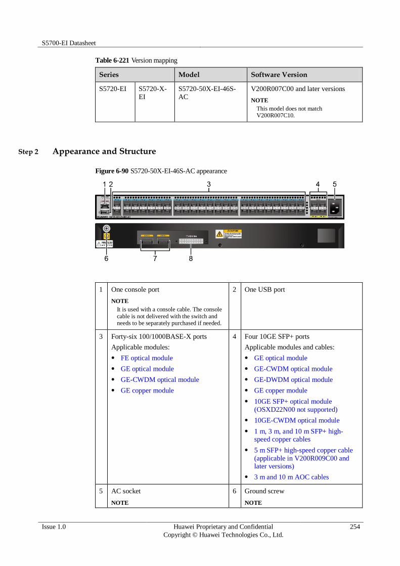
S5700-EI Datasheet
Issue 1.0 Huawei Proprietary and Confidential
Copyright © Huawei Technologies Co., Ltd.
254
Table 6-221 Version mapping
Series Model Software Version
S5720-EI S5720-X-
EI
S5720-50X-EI-46S-
AC
V200R007C00 and later versions
NOTE
This model does not match V200R007C10.
Step 2 Appearance and Structure
Figure 6-90 S5720-50X-EI-46S-AC appearance
1 One console port
NOTE
It is used with a console cable. The console cable is not delivered with the switch and needs to be separately purchased if needed.
2 One USB port
3 Forty-six 100/1000BASE-X ports
Applicable modules:
FE optical module
GE optical module
GE-CWDM optical module
GE copper module
4 Four 10GE SFP+ ports
Applicable modules and cables:
GE optical module
GE-CWDM optical module
GE-DWDM optical module
GE copper module
10GE SFP+ optical module
(OSXD22N00 not supported)
10GE-CWDM optical module
1 m, 3 m, and 10 m SFP+ high-speed copper cables
5 m SFP+ high-speed copper cable
(applicable in V200R009C00 and later versions)
3 m and 10 m AOC cables
5 AC socket
NOTE
6 Ground screw
NOTE

S5700-EI Datasheet
Issue 1.0 Huawei Proprietary and Confidential
Copyright © Huawei Technologies Co., Ltd.
255
It is used with an AC power cable. It is used with a ground cable.
7 Two QSFP+ stack optical ports
Applicable modules and cables:
QSFP+ optical module (only QSFP-
40G-SR4 and QSFP-40G-iSR
supported)
1 m, 3 m, and 5 m QSFP+ high-speed copper cables
10 m QSFP+ AOC cable (applicable in V200R009C00 and later versions)
8 RPS socket
NOTE
It is used with an RPS cable, which is not hot swappable.
Step 3 Port Description
100/1000BASE-X port
A 100/1000BASE-X port can send and receive data at 100 Mbit/s or 1000 Mbit/s. Table 3-641
describes the attributes of a 100/1000BASE-X port.
Table 6-222 Attributes of a 100/1000BASE-X port
Attribute Description
Connector type LC/PC
Optical interface
attributes
Depend on the optical module used
Standards compliance
IEEE802.3z
Working mode 100/1000 Mbit/s auto-sensing
Full-duplex
10GE SFP+ port
A 10GE SFP+ Ethernet optical port supports auto-sensing to 1000 Mbit/s. It sends and
receives service data at 1000 Mbit/s or 10 Gbit/s. Table 3-642 describes the attributes of a
10GE SFP+ Ethernet optical port.
Table 6-223 Attributes of a 10GE SFP+ port
Attribute Description
Connector type LC/PC
Optical port
attributes
Depend on the optical module used
Standards
compliance
IEEE802.3ae
Working mode GE/10GE auto-sensing

S5700-EI Datasheet
Issue 1.0 Huawei Proprietary and Confidential
Copyright © Huawei Technologies Co., Ltd.
256
Attribute Description
Full-duplex
QSFP+ stack optical port
QSFP+ stack optical ports can only be used for stack connection. Table 3-643 describes the
attributes of a QSFP+ stack optical port.
Table 6-224 Attributes of a QSFP+ stack optical port
Attribute Description
Connector type MPO
Optical port
attributes
Depend on the optical module used
Standards
compliance
IEEE802.3ae
Working Mode Full-duplex
Console port
The console port is connected to a console for on-site configuration. The port must use a
console cable. The console port is used when a switch is powered on for the first time. For
details about the attributes of a console port, see Table 3-644.
Table 6-225 Attributes of a console port
Attribute Description
Connector type RJ45
Standards
compliance
RS-232
Working mode Duplex Universal Asynchronous Receiver/Transmitter (UART)
Baud rate 9600 bit/s, 19200 bit/s, 38400 bit/s, 57600 bit/s, or 115200 bit/s
Default value: 9600 bit/s
USB port
The USB port can have a USB flash drive connected to upgrade the switch, or transfer
configuration files or other files. The USB port of the S5720-EI does not support USB 1.1 and
can only connect to a USB flash drive that complies with USB 2.0 and supports the Linux
operating system.

S5700-EI Datasheet
Issue 1.0 Huawei Proprietary and Confidential
Copyright © Huawei Technologies Co., Ltd.
257
Step 4 Indicator Description
The S5720-50X-EI-46S-AC has 46 downlink optical port indicators, whereas the S5720-50X-
EI-AC has 46 downlink electrical port indicators. Symbols and meanings of other indicators
on the two switch models are the same. For details, see Indicator Description.
Step 5 Power Supply Configuration
The S5720-50X-EI-46S-AC has a built-in power module and does not support pluggable
power modules. It can connect to an RPS1800 power supply for power redundancy.
Figure 3-243 shows the power supply mode of a built-in AC power module. The built-in AC
power module (PWR) receives power from an external power source and provides a 12 V
output to the chassis.
Figure 6-91 Power supply mode of a built-in AC power module
Motherboard
GND12V
PWR
L N PGND
L: live wire N: neutral wire PGND: protection ground GND: 12 V reference ground
Step 6 Heat Dissipation
The S5720-50X-EI-46S-AC has built-in fans for forced air cooling. Air flows in from the left
side and front panel, and exhausts from the right side.
This figure only shows the airflow direction and does not depict the actual device.
Step 7 Technical Specifications
Table 3-645 lists technical specifications of the S5720-50X-EI-46S-AC.

S5700-EI Datasheet
Issue 1.0 Huawei Proprietary and Confidential
Copyright © Huawei Technologies Co., Ltd.
258
Table 6-226 Technical specifications
Item Description
Memory (RAM) 2 GB
Flash 340 MB
Mean time between
failures (MTBF)
67.59 years
Mean time to repair
(MTTR)
2 hours
Availability > 0.99999
Service port surge
protection
NA
Power supply surge
protection
±6 kV in differential mode, ±6 kV in common mode
Dimensions (W
x D x H)
442.0 mm x 220.0 mm x 43.6 mm (17.4 in. x 8.7 in. x 1.72 in.)
Weight ≤ 8 kg (17.64 lb)
Stack ports Two fixed QSFP+ stack ports on the rear card
RPS Supported
PoE Not supported
Rated voltage range 100 V AC to 240 V AC, 50/60 Hz
Maximum voltage
range
90 V AC to 264 V AC, 47 Hz to 63 Hz
Maximum power
consumption
(100% throughput, full speed of fans)
81.5 W
Operating
temperature
0°C to 45°C (32°F to 113°F) at an altitude of 0-1800 m (0-5096 ft.)
NOTE
When the altitude is 1800-5000 m (5096-16404 ft.), the highest operating temperature reduces by 1°C (1.8°F) every time the altitude increases by 220 m (722 ft.).
Storage
temperature
-40°C to +70°C (-40°F to +158°F)
Noise under normal
temperature (27°C, sound power)
< 51.1 dBA
Relative humidity 5% to 95%, noncondensing
Operating altitude 0-5000 m (0-16404 ft.)
Certification EMC certification

S5700-EI Datasheet
Issue 1.0 Huawei Proprietary and Confidential
Copyright © Huawei Technologies Co., Ltd.
259
Item Description
Safety certification
Manufacturing certification
6.3.23 S5720-50X-EI-46S-DC
Step 1 Version Mapping
Table 3-646 lists the mapping between the S5720-50X-EI-46S-DC chassis and software
versions.
Table 6-227 Version mapping
Series Model Software Version
S5720-EI S5720-X-
EI
S5720-50X-EI-46S-
DC
V200R009C00 and later versions
Step 2 Appearance and Structure
Figure 6-92 S5720-50X-EI-46S-DC appearance
1 One console port
NOTE
It is used with a console cable. The console cable is not delivered with the switch and needs to be separately purchased if needed.
2 One USB port
3 Forty-six 100/1000BASE-X ports
Applicable modules:
FE optical module
GE optical module
GE-CWDM optical module
GE copper module
4 Four 10GE SFP+ ports
Applicable modules and cables:
GE optical module
GE-CWDM optical module
GE-DWDM optical module
GE copper module

S5700-EI Datasheet
Issue 1.0 Huawei Proprietary and Confidential
Copyright © Huawei Technologies Co., Ltd.
260
10GE SFP+ optical module (OSXD22N00 not supported)
10GE-CWDM optical module
1 m, 3 m, and 10 m SFP+ high-speed copper cables
5 m SFP+ high-speed copper cable
(applicable in V200R009C00 and
later versions)
3 m and 10 m AOC cables
5 DC power terminal
NOTE
It is used together with a DC Power Cable.
6 Ground screw
NOTE
It is used with a ground cable.
7 Two QSFP+ stack optical ports
Applicable modules and cables:
QSFP+ optical module (only QSFP-
40G-SR4 and QSFP-40G-iSR supported)
1 m, 3 m, and 5 m QSFP+ high-speed copper cables
10 m QSFP+ AOC cable (applicable in V200R009C00 and later versions)
8 RPS socket
NOTE
It is used with an RPS cable, which is not hot swappable.
Step 3 Port Description
100/1000BASE-X port
A 100/1000BASE-X port can send and receive data at 100 Mbit/s or 1000 Mbit/s. Table 3-647
describes the attributes of a 100/1000BASE-X port.
Table 6-228 Attributes of a 100/1000BASE-X port
Attribute Description
Connector type LC/PC
Optical interface
attributes
Depend on the optical module used
Standards
compliance
IEEE802.3z
Working mode 100/1000 Mbit/s auto-sensing
Full-duplex
10GE SFP+ port
A 10GE SFP+ Ethernet optical port supports auto-sensing to 1000 Mbit/s. It sends and
receives service data at 1000 Mbit/s or 10 Gbit/s. Table 3-648 describes the attributes of a
10GE SFP+ Ethernet optical port.
S5700-EI Datasheet
Issue 1.0 Huawei Proprietary and Confidential
Copyright © Huawei Technologies Co., Ltd.
261
Table 6-229 Attributes of a 10GE SFP+ port
Attribute Description
Connector type LC/PC
Optical port
attributes
Depend on the optical module used
Standards compliance
IEEE802.3ae
Working mode GE/10GE auto-sensing
Full-duplex
QSFP+ stack optical port
QSFP+ stack optical ports can only be used for stack connection. Table 3-649 describes the
attributes of a QSFP+ stack optical port.
Table 6-230 Attributes of a QSFP+ stack optical port
Attribute Description
Connector type MPO
Optical port
attributes
Depend on the optical module used
Standards
compliance
IEEE802.3ae
Working Mode Full-duplex
Console port
The console port is connected to a console for on-site configuration. The port must use a
console cable. The console port is used when a switch is powered on for the first time. For
details about the attributes of a console port, see Table 3-650.
Table 6-231 Attributes of a console port
Attribute Description
Connector type RJ45
Standards
compliance
RS-232
Working mode Duplex Universal Asynchronous Receiver/Transmitter (UART)
Baud rate 9600 bit/s, 19200 bit/s, 38400 bit/s, 57600 bit/s, or 115200 bit/s
Default value: 9600 bit/s

S5700-EI Datasheet
Issue 1.0 Huawei Proprietary and Confidential
Copyright © Huawei Technologies Co., Ltd.
262
USB port
The USB port can have a USB flash drive connected to upgrade the switch, or transfer
configuration files or other files. The USB port of the S5720-EI does not support USB 1.1 and
can only connect to a USB flash drive that complies with USB 2.0 and supports the Linux
operating system.
Step 4 Indicator Description
The S5720-50X-EI-46S-DC has 46 downlink optical port indicators, whereas the S5720-50X-
EI-AC has 46 downlink electrical port indicators. Symbols and meanings of other indicators
on the two switch models are the same. For details, see Indicator Description.
Step 5 Power Supply Configuration
The S5720-50X-EI-46S-DC has a built-in power module and does not support pluggable
power modules. It can connect to an RPS1800 power supply for power redundancy.
Figure 3-245 shows the power supply mode of a single DC power module. The built-in DC
power module (PWR) receives DC power from an external power source and provides a 12 V
output to the chassis.
Figure 6-93 Power supply by a single DC power module
Motherboard
GND12V
PWR
NEG RTN
NEG: negative cable RTN: positive cable GND: 12 V reference ground
Step 6 Heat Dissipation
The S5720-50X-EI-46S-DC has built-in fans for forced air cooling. Air flows in from the left
side and front panel, and exhausts from the right side.

S5700-EI Datasheet
Issue 1.0 Huawei Proprietary and Confidential
Copyright © Huawei Technologies Co., Ltd.
263
This figure only shows the airflow direction and does not depict the actual device.
Step 7 Technical Specifications
Table 3-651 lists technical specifications of the S5720-50X-EI-46S-DC.
Table 6-232 Technical specifications
Item Description
Memory (RAM) 2 GB
Flash 340 MB
Mean time between
failures (MTBF)
67.59 years
Mean time to repair
(MTTR)
2 hours
Availability > 0.99999
Service port surge
protection
NA
Power supply surge
protection
±1 kV in differential mode, ±2 kV in common mode
Dimensions (W
x D x H)
442.0 mm x 220.0 mm x 43.6 mm (17.4 in. x 8.7 in. x 1.72 in.)
Weight ≤ 8 kg (17.64 lb)
Stack ports Two fixed QSFP+ stack ports on the rear card
RPS Supported
PoE Not supported
Rated voltage range -48 V DC to -60 V DC
Maximum voltage
range
-36 V DC to -72 V DC
Maximum power
consumption
(100% throughput, full speed of fans)
81.5 W
Operating
temperature
0°C to 45°C (32°F to 113°F) at an altitude of 0-1800 m (0-5096 ft.)
NOTE
When the altitude is 1800-5000 m (5096-16404 ft.), the highest operating temperature reduces by 1°C (1.8°F) every time the altitude increases by 220 m (722 ft.).
Storage
temperature
-40°C to +70°C (-40°F to +158°F)

S5700-EI Datasheet
Issue 1.0 Huawei Proprietary and Confidential
Copyright © Huawei Technologies Co., Ltd.
264
Item Description
Noise under normal
temperature (27°C, sound power)
< 51.1 dBA
Relative humidity 5% to 95%, noncondensing
Operating altitude 0-2000 m (0-6562 ft.)
Certification EMC certification
Safety certification
Manufacturing certification
6.3.24 S5720-52X-EI-AC
Step 1 Version Mapping
Table 3-652 lists the mapping between the S5720-52X-EI-AC chassis and software versions.
Table 6-233 Version mapping
Series Model Software Version
S5720-EI S5720-X-
EI
S5720-52X-EI-AC V200R007C00 and later versions
NOTE
This model does not match V200R007C10.
Step 2 Appearance and Structure
Figure 6-94 S5720-52X-EI-AC appearance
1 Forty-eight 10/100/1000BASE-T ports 2 Four 10GE SFP+ ports
Applicable modules and cables:
GE optical module

S5700-EI Datasheet
Issue 1.0 Huawei Proprietary and Confidential
Copyright © Huawei Technologies Co., Ltd.
265
GE-CWDM optical module
GE-DWDM optical module
GE copper module
10GE SFP+ optical module
(OSXD22N00 not supported)
10GE-CWDM optical module
1 m, 3 m, and 10 m SFP+ high-speed copper cables
5 m SFP+ high-speed copper cable
(applicable in V200R009C00 and
later versions)
3 m and 10 m AOC cables
3 One ETH management port 4 One mini USB port
5 One console port
NOTE
It is used with a console cable. The console
cable is not delivered with the switch and needs to be separately purchased if needed.
6 One USB port
7 Ground screw
NOTE
It is used with a ground cable.
8 Two QSFP+ stack optical ports
Applicable modules and cables:
QSFP+ optical module (only QSFP-
40G-SR4 and QSFP-40G-iSR
supported)
1 m, 3 m, and 5 m QSFP+ high-speed copper cables
10 m QSFP+ AOC cable (applicable
in V200R009C00 and later
versions)
9 RPS socket
NOTE
It is used with an RPS cable, which is not hot swappable.
10 AC socket
NOTE
It is used with an AC power cable.
Step 3 Port Description
10/100/1000BASE-T port
A 10/100/1000BASE-T Ethernet electrical port sends and receives service data at
10/100/1000 Mbit/s, and must use network cables. Table 3-653 describes the attributes of a
10/100/1000BASE-T Ethernet electrical port.
Table 6-234 Attributes of a 10/100/1000BASE-T Ethernet electrical port
Attribute Description
Connector type RJ45
Standards IEEE802.3, IEEE802.3u, IEEE802.3ab

S5700-EI Datasheet
Issue 1.0 Huawei Proprietary and Confidential
Copyright © Huawei Technologies Co., Ltd.
266
Attribute Description
compliance
Working mode 10/100/1000 Mbit/s auto-sensing
Full-duplex
Maximum
transmission distance
100 m
10GE SFP+ port
A 10GE SFP+ Ethernet optical port supports auto-sensing to 1000 Mbit/s. It sends and
receives service data at 1000 Mbit/s or 10 Gbit/s. Table 3-654 describes the attributes of a
10GE SFP+ Ethernet optical port.
Table 6-235 Attributes of a 10GE SFP+ port
Attribute Description
Connector type LC/PC
Optical port
attributes
Depend on the optical module used
Standards
compliance
IEEE802.3ae
Working mode GE/10GE auto-sensing
Full-duplex
QSFP+ stack optical port
QSFP+ stack optical ports can only be used for stack connection. Table 3-655 describes the
attributes of a QSFP+ stack optical port.
Table 6-236 Attributes of a QSFP+ stack optical port
Attribute Description
Connector type MPO
Optical port
attributes
Depend on the optical module used
Standards
compliance
IEEE802.3ae
Working Mode Full-duplex
Console port

S5700-EI Datasheet
Issue 1.0 Huawei Proprietary and Confidential
Copyright © Huawei Technologies Co., Ltd.
267
The console port is connected to a console for on-site configuration. The port must use a
console cable. The console port is used when a switch is powered on for the first time. For
details about the attributes of a console port, see Table 3-656.
Table 6-237 Attributes of a console port
Attribute Description
Connector type RJ45
Standards
compliance
RS-232
Working mode Duplex Universal Asynchronous Receiver/Transmitter (UART)
Baud rate 9600 bit/s, 19200 bit/s, 38400 bit/s, 57600 bit/s, or 115200 bit/s
Default value: 9600 bit/s
Mini USB port
The mini USB port is connected to a console for on-site configuration. When both the Mini
USB and console port have a cable connected, only the Mini USB port works.
ETH management port
You can connect a switch to a configuration terminal or network management workstation
through the ETH management port to configure the switch locally or remotely. The port must
use a network cable. You can choose to download the software package through the ETH
management port in the BootLoad menu. File transfer through the ETH management port is
faster than transfer through the console port. For details on how to use the ETH management
port, see the Configuration Guide - Basic Configurations. Table 3-657 describes the attributes
of an ETH management port.
Table 6-238 Attributes of an ETH management port
Attribute Description
Connector type RJ45
Standards
compliance
IEEE802.3
Working mode 10/100 Mbit/s auto-sensing
Full duplex
Maximum
transmission distance
100 m
USB port
The USB port can have a USB flash drive connected to upgrade the switch, or transfer
configuration files or other files. The USB port of the S5720-EI does not support USB 1.1 and

S5700-EI Datasheet
Issue 1.0 Huawei Proprietary and Confidential
Copyright © Huawei Technologies Co., Ltd.
268
can only connect to a USB flash drive that complies with USB 2.0 and supports the Linux
operating system.
Step 4 Indicator Description
The S5720-52X-EI-AC have the same types of indicators as the S5720-32X-EI-AC. For
details, see Indicator Description.
Step 5 Power Supply Configuration
The S5720-52X-EI-AC has a built-in power module and does not support pluggable power
modules. It can connect to an RPS1800 power supply for power redundancy.
Figure 3-247 shows the power supply mode of a built-in AC power module. The built-in AC
power module (PWR) receives power from an external power source and provides a 12 V
output to the chassis.
Figure 6-95 Power supply mode of a built-in AC power module
Motherboard
GND12V
PWR
L N PGND
L: live wire N: neutral wire PGND: protection ground GND: 12 V reference ground
Step 6 Heat Dissipation
The S5720-52X-EI-AC has built-in fans for forced air cooling. The airflow direction is left-
to-right.
Step 7 Technical Specifications
Table 3-658 lists technical specifications of the S5720-52X-EI-AC.

S5700-EI Datasheet
Issue 1.0 Huawei Proprietary and Confidential
Copyright © Huawei Technologies Co., Ltd.
269
Table 6-239 Technical specifications
Item Description
Memory (RAM) 2 GB
Flash 340 MB
Mean time between
failures (MTBF)
73.12 years
Mean time to repair
(MTTR)
2 hours
Availability > 0.99999
Service port surge
protection
Common mode: ±6 kV
Power supply surge
protection
±6 kV in differential mode, ±6 kV in common mode
Dimensions (W
x D x H)
442.0 mm x 220.0 mm x 43.6 mm (17.4 in. x 8.7 in. x 1.72 in.)
Weight ≤ 8 kg (17.64 lb)
Stack ports Two fixed QSFP+ stack ports on the rear card
RPS Supported
PoE Not supported
Rated voltage range 100 V AC to 240 V AC, 50/60 Hz
Maximum voltage
range
90 V AC to 264 V AC, 47 Hz to 63 Hz
Maximum power
consumption
(100% throughput, full speed of fans)
61.5 W
Operating
temperature
0°C to 45°C (32°F to 113°F) at an altitude of 0-1800 m (0-5096 ft.)
NOTE
When the altitude is 1800-5000 m (5096-16404 ft.), the highest operating temperature reduces by 1°C (1.8°F) every time the altitude increases by 220 m (722 ft.).
Storage
temperature
-40°C to +70°C (-40°F to +158°F)
Noise under normal
temperature (27°C, sound power)
< 49.3 dBA
Relative humidity 5% to 95%, noncondensing
Operating altitude 0-5000 m (0-16404 ft.)
Certification EMC certification

S5700-EI Datasheet
Issue 1.0 Huawei Proprietary and Confidential
Copyright © Huawei Technologies Co., Ltd.
270
Item Description
Safety certification
Manufacturing certification
6.3.25 S5720-32P-EI-AC
Step 1 Version Mapping
Table 3-659 lists the mapping between the S5720-32P-EI-AC chassis and software versions.
Table 6-240 Version mapping
Series Model Software Version
S5720-EI S5720-P-
EI
S5720-32P-EI-AC V200R007C00 and later versions
NOTE
This model does not match V200R007C10.
Step 2 Appearance and Structure
Figure 6-96 S5720-32P-EI-AC appearance
1 Twenty-four 10/100/1000BASE-T
ports
2 Four 100/1000BASE-X ports
Applicable modules:
FE optical module
GE optical module
GE-CWDM optical module
GE-DWDM optical module
GE copper module
3 Four 1000BASE-X ports
Applicable modules:
4 One mini USB port

S5700-EI Datasheet
Issue 1.0 Huawei Proprietary and Confidential
Copyright © Huawei Technologies Co., Ltd.
271
GE optical module
GE-CWDM optical module
GE-DWDM optical module
GE copper module (only 1000
Mbit/s supported)
5 One console port
NOTE
It is used with a console cable. The console cable is not delivered with the switch and needs to be separately purchased if needed.
6 One ETH management port
7 One USB port 8 AC socket
NOTE
It is used with an AC power cable.
9 Jack for AC terminal locking latch
NOTE
The AC terminal locking latch is not delivered with the switch.
10 Ground screw
NOTE
It is used with a ground cable.
11 Two QSFP+ stack optical ports
Applicable modules and cables:
QSFP+ optical module (only
QSFP-40G-SR4 and QSFP-40G-iSR supported)
1 m, 3 m, and 5 m QSFP+ high-speed copper cables
10 m QSFP+ AOC cable
(applicable in V200R009C00 and later versions)
12 RPS socket
NOTE
It is used with an RPS cable, which is not hot swappable.
Step 3 Port Description
10/100/1000BASE-T port
A 10/100/1000BASE-T Ethernet electrical port sends and receives service data at
10/100/1000 Mbit/s, and must use network cables. Table 3-660 describes the attributes of a
10/100/1000BASE-T Ethernet electrical port.
Table 6-241 Attributes of a 10/100/1000BASE-T Ethernet electrical port
Attribute Description
Connector type RJ45
Standards compliance
IEEE802.3, IEEE802.3u, IEEE802.3ab
Working mode 10/100/1000 Mbit/s auto-sensing
Full-duplex
Maximum
transmission
100 m
S5700-EI Datasheet
Issue 1.0 Huawei Proprietary and Confidential
Copyright © Huawei Technologies Co., Ltd.
272
Attribute Description
distance
100/1000BASE-X port
A 100/1000BASE-X port can send and receive data at 100 Mbit/s or 1000 Mbit/s. Table 3-661
describes the attributes of a 100/1000BASE-X port.
Table 6-242 Attributes of a 100/1000BASE-X port
Attribute Description
Connector type LC/PC
Optical interface
attributes
Depend on the optical module used
Standards
compliance
IEEE802.3z
Working mode 100/1000 Mbit/s auto-sensing
Full-duplex
1000BASE-X port
A 1000BASE-X Ethernet optical port sends and receives service data at 1000 Mbit/s. Table 3-
662 describes the attributes of a 1000BASE-X Ethernet optical port.
Table 6-243 Attributes of a 1000BASE-X Ethernet optical port
Attribute Description
Connector type LC/PC
Optical port
attributes
Depend on the optical module used
Standards
compliance
IEEE802.3z
Working mode 1000 Mbit/s
Full-duplex
QSFP+ stack optical port
QSFP+ stack optical ports can only be used for stack connection. Table 3-663 describes the
attributes of a QSFP+ stack optical port.

S5700-EI Datasheet
Issue 1.0 Huawei Proprietary and Confidential
Copyright © Huawei Technologies Co., Ltd.
273
Table 6-244 Attributes of a QSFP+ stack optical port
Attribute Description
Connector type MPO
Optical port
attributes
Depend on the optical module used
Standards compliance
IEEE802.3ae
Working Mode Full-duplex
Console port
The console port is connected to a console for on-site configuration. The port must use a
console cable. The console port is used when a switch is powered on for the first time. For
details about the attributes of a console port, see Table 3-664.
Table 6-245 Attributes of a console port
Attribute Description
Connector type RJ45
Standards
compliance
RS-232
Working mode Duplex Universal Asynchronous Receiver/Transmitter (UART)
Baud rate 9600 bit/s, 19200 bit/s, 38400 bit/s, 57600 bit/s, or 115200 bit/s
Default value: 9600 bit/s
Mini USB port
The mini USB port is connected to a console for on-site configuration. When both the Mini
USB and console port have a cable connected, only the Mini USB port works.
ETH management port
You can connect a switch to a configuration terminal or network management workstation
through the ETH management port to configure the switch locally or remotely. The port must
use a network cable. You can choose to download the software package through the ETH
management port in the BootLoad menu. File transfer through the ETH management port is
faster than transfer through the console port. For details on how to use the ETH management
port, see the Configuration Guide - Basic Configurations. Table 3-665 describes the attributes
of an ETH management port.
Table 6-246 Attributes of an ETH management port
Attribute Description
Connector type RJ45

S5700-EI Datasheet
Issue 1.0 Huawei Proprietary and Confidential
Copyright © Huawei Technologies Co., Ltd.
274
Attribute Description
Standards
compliance
IEEE802.3
Working mode 10/100 Mbit/s auto-sensing
Full duplex
Maximum
transmission
distance
100 m
USB port
The USB port can have a USB flash drive connected to upgrade the switch, or transfer
configuration files or other files. The USB port of the S5720-EI does not support USB 1.1 and
can only connect to a USB flash drive that complies with USB 2.0 and supports the Linux
operating system.
Step 4 Indicator Description
The S5720-32P-EI-AC have the same types of indicators as the S5720-32X-EI-AC. For
details, see Indicator Description.
Step 5 Power Supply Configuration
The S5720-32P-EI-AC has a built-in power module and does not support pluggable power
modules. It can connect to an RPS1800 power supply for power redundancy.
Figure 3-249 shows the power supply mode of a built-in AC power module. The built-in AC
power module (PWR) receives power from an external power source and provides a 12 V
output to the chassis.
Figure 6-97 Power supply mode of a built-in AC power module
Motherboard
GND12V
PWR
L N PGND
L: live wire N: neutral wire PGND: protection ground GND: 12 V reference ground
Step 6 Heat Dissipation
The S5720-32P-EI-AC has built-in fans for forced air cooling. Air flows in from the left side and front panel, and exhausts from the right side.

S5700-EI Datasheet
Issue 1.0 Huawei Proprietary and Confidential
Copyright © Huawei Technologies Co., Ltd.
275
Step 7 Technical Specifications
Table 3-666 lists technical specifications of the S5720-32P-EI-AC.
Table 6-247 Technical specifications
Item Description
Memory (RAM) 2 GB
Flash 340 MB
Mean time between
failures (MTBF)
80.32 years
Mean time to repair
(MTTR)
2 hours
Availability > 0.99999
Service port surge
protection
Common mode: ±6 kV
Power supply surge
protection
±6 kV in differential mode, ±6 kV in common mode
Dimensions (W
x D x H)
442.0 mm x 220.0 mm x 43.6 mm (17.4 in. x 8.7 in. x 1.72 in.)
Weight ≤ 8 kg (17.64 lb)
Stack ports Two fixed QSFP+ stack ports on the rear card
RPS Supported
PoE Not supported
Rated voltage range 100 V AC to 240 V AC, 50/60 Hz
Maximum voltage
range
90 V AC to 264 V AC, 47 Hz to 63 Hz
Maximum power
consumption
(100% throughput, full speed of fans)
50.7 W

S5700-EI Datasheet
Issue 1.0 Huawei Proprietary and Confidential
Copyright © Huawei Technologies Co., Ltd.
276
Item Description
Operating
temperature
0°C to 45°C (32°F to 113°F) at an altitude of 0-1800 m (0-5096 ft.)
NOTE
When the altitude is 1800-5000 m (5096-16404 ft.), the highest operating temperature reduces by 1°C (1.8°F) every time the altitude increases by 220 m (722 ft.).
Storage
temperature
-40°C to +70°C (-40°F to +158°F)
Noise under normal
temperature (27°C, sound power)
< 49.3 dBA
Relative humidity 5% to 95%, noncondensing
Operating altitude 0-5000 m (0-16404 ft.)
Certification EMC certification
Safety certification
Manufacturing certification
6.3.26 S5720-52P-EI-AC
Step 1 Version Mapping
Table 3-667 lists the mapping between the S5720-52P-EI-AC chassis and software versions.
Table 6-248 Version mapping
Series Model Software Version
S5720-EI S5720-P-
EI
S5720-52P-EI-AC V200R007C00 and later versions
NOTE
This model does not match V200R007C10.

S5700-EI Datasheet
Issue 1.0 Huawei Proprietary and Confidential
Copyright © Huawei Technologies Co., Ltd.
277
Step 2 Appearance and Structure
Figure 6-98 S5720-52P-EI-AC appearance
1 Forty-eight 10/100/1000BASE-T ports 2 Four 1000BASE-X ports
Applicable modules:
GE optical module
GE-CWDM optical module
GE-DWDM optical module
GE copper module (only 1000 Mbit/s supported)
3 One ETH management port 4 One mini USB port
5 One console port
NOTE
It is used with a console cable. The console cable is not delivered with the switch and needs to be separately purchased if needed.
6 One USB port
7 Ground screw
NOTE
It is used with a ground cable.
8 Two QSFP+ stack optical ports
Applicable modules and cables:
QSFP+ optical module (only QSFP-
40G-SR4 and QSFP-40G-iSR supported)
1 m, 3 m, and 5 m QSFP+ high-
speed copper cables
10 m QSFP+ AOC cable (applicable
in V200R009C00 and later versions)
9 RPS socket
NOTE
It is used with an RPS cable, which is not hot swappable.
10 AC socket
NOTE
It is used with an AC power cable.
Step 3 Port Description
10/100/1000BASE-T port

S5700-EI Datasheet
Issue 1.0 Huawei Proprietary and Confidential
Copyright © Huawei Technologies Co., Ltd.
278
A 10/100/1000BASE-T Ethernet electrical port sends and receives service data at
10/100/1000 Mbit/s, and must use network cables. Table 3-668 describes the attributes of a
10/100/1000BASE-T Ethernet electrical port.
Table 6-249 Attributes of a 10/100/1000BASE-T Ethernet electrical port
Attribute Description
Connector type RJ45
Standards
compliance
IEEE802.3, IEEE802.3u, IEEE802.3ab
Working mode 10/100/1000 Mbit/s auto-sensing
Full-duplex
Maximum
transmission distance
100 m
1000BASE-X port
A 1000BASE-X Ethernet optical port sends and receives service data at 1000 Mbit/s. Table 3-
669 describes the attributes of a 1000BASE-X Ethernet optical port.
Table 6-250 Attributes of a 1000BASE-X Ethernet optical port
Attribute Description
Connector type LC/PC
Optical port
attributes
Depend on the optical module used
Standards
compliance
IEEE802.3z
Working mode 1000 Mbit/s
Full-duplex
QSFP+ stack optical port
QSFP+ stack optical ports can only be used for stack connection. Table 3-670 describes the
attributes of a QSFP+ stack optical port.
Table 6-251 Attributes of a QSFP+ stack optical port
Attribute Description
Connector type MPO
Optical port
attributes
Depend on the optical module used

S5700-EI Datasheet
Issue 1.0 Huawei Proprietary and Confidential
Copyright © Huawei Technologies Co., Ltd.
279
Attribute Description
Standards
compliance
IEEE802.3ae
Working Mode Full-duplex
Console port
The console port is connected to a console for on-site configuration. The port must use a
console cable. The console port is used when a switch is powered on for the first time. For
details about the attributes of a console port, see Table 3-671.
Table 6-252 Attributes of a console port
Attribute Description
Connector type RJ45
Standards
compliance
RS-232
Working mode Duplex Universal Asynchronous Receiver/Transmitter (UART)
Baud rate 9600 bit/s, 19200 bit/s, 38400 bit/s, 57600 bit/s, or 115200 bit/s
Default value: 9600 bit/s
Mini USB port
The mini USB port is connected to a console for on-site configuration. When both the Mini
USB and console port have a cable connected, only the Mini USB port works.
ETH management port
You can connect a switch to a configuration terminal or network management workstation
through the ETH management port to configure the switch locally or remotely. The port must
use a network cable. You can choose to download the software package through the ETH
management port in the BootLoad menu. File transfer through the ETH management port is
faster than transfer through the console port. For details on how to use the ETH management
port, see the Configuration Guide - Basic Configurations. Table 3-672 describes the attributes
of an ETH management port.
Table 6-253 Attributes of an ETH management port
Attribute Description
Connector type RJ45
Standards compliance
IEEE802.3
Working mode 10/100 Mbit/s auto-sensing
Full duplex

S5700-EI Datasheet
Issue 1.0 Huawei Proprietary and Confidential
Copyright © Huawei Technologies Co., Ltd.
280
Attribute Description
Maximum
transmission distance
100 m
USB port
The USB port can have a USB flash drive connected to upgrade the switch, or transfer
configuration files or other files. The USB port of the S5720-EI does not support USB 1.1 and
can only connect to a USB flash drive that complies with USB 2.0 and supports the Linux
operating system.
Step 4 Indicator Description
The S5720-52P-EI-AC have the same types of indicators as the S5720-32X-EI-AC. For
details, see Indicator Description.
Step 5 Power Supply Configuration
The S5720-52P-EI-AC has a built-in power module and does not support pluggable power
modules. It can connect to an RPS1800 power supply for power redundancy.
Figure 3-251 shows the power supply mode of a built-in AC power module. The built-in AC
power module (PWR) receives power from an external power source and provides a 12 V
output to the chassis.
Figure 6-99 Power supply mode of a built-in AC power module
Motherboard
GND12V
PWR
L N PGND
L: live wire N: neutral wire PGND: protection ground GND: 12 V reference ground
Step 6 Heat Dissipation
The S5720-52P-EI-AC has built-in fans for forced air cooling. The airflow direction is left-to-
right.

S5700-EI Datasheet
Issue 1.0 Huawei Proprietary and Confidential
Copyright © Huawei Technologies Co., Ltd.
281
Step 7 Technical Specifications
Table 3-673 lists technical specifications of the S5720-52P-EI-AC.
Table 6-254 Technical specifications
Item Description
Memory (RAM) 2 GB
Flash 340 MB
Mean time between
failures (MTBF)
73.12 years
Mean time to repair
(MTTR)
2 hours
Availability > 0.99999
Service port surge
protection
Common mode: ±6 kV
Power supply surge
protection
±6 kV in differential mode, ±6 kV in common mode
Dimensions (W
x D x H)
442.0 mm x 220.0 mm x 43.6 mm (17.4 in. x 8.7 in. x 1.72 in.)
Weight ≤ 8 kg (17.64 lb)
Stack ports Two fixed QSFP+ stack ports on the rear card
RPS Supported
PoE Not supported
Rated voltage range 100 V AC to 240 V AC, 50/60 Hz
Maximum voltage
range
90 V AC to 264 V AC, 47 Hz to 63 Hz
Maximum power
consumption
(100% throughput, full speed of fans)
60.3 W
Operating 0°C to 45°C (32°F to 113°F) at an altitude of 0-1800 m (0-5096 ft.)

S5700-EI Datasheet
Issue 1.0 Huawei Proprietary and Confidential
Copyright © Huawei Technologies Co., Ltd.
282
Item Description
temperature NOTE
When the altitude is 1800-5000 m (5096-16404 ft.), the highest operating temperature reduces by 1°C (1.8°F) every time the altitude increases by 220 m (722 ft.).
Storage
temperature
-40°C to +70°C (-40°F to +158°F)
Noise under normal
temperature (27°C,
sound power)
< 49.3 dBA
Relative humidity 5% to 95%, noncondensing
Operating altitude 0-5000 m (0-16404 ft.)
Certification EMC certification
Safety certification
Manufacturing certification
7 Safety and Regulatory Compliance
Table 7-1 lists the safety and regulatory compliance of S5700-EI.

S5700-EI Datasheet
Issue 1.0 Huawei Proprietary and Confidential
Copyright © Huawei Technologies Co., Ltd.
283
Table 7-1 S5700-EI safety and regulatory compliance
Certification Category Description
Safety
IEC 60950-1
EN 60950-1/A11/A12
UL 60950-1
CSA C22.2 No 60950-1
AS/NZS 60950.1
CNS 14336-1
IEC60825-1
IEC60825-2
EN60825-1
EN60825-2
Electromagnetic
Compatibility (EMC)
CISPR22 Class A
CISPR24
EN55022 Class A
EN55024
ETSI EN 300 386 Class A
CFR 47 FCC Part 15 Class A
ICES 003 Class A
AS/NZS CISPR22 Class A
VCCI Class A
IEC61000-4-2
ITU-T K 20
ITU-T K 21
ITU-T K 44
CNS13438
Environment
RoHS
REACH
WEEE

S5700-EI Datasheet
Issue 1.0 Huawei Proprietary and Confidential
Copyright © Huawei Technologies Co., Ltd.
284
EMC: electromagnetic compatibility
CISPR: International Special Committee on Radio Interference
EN: European Standard
ETSI: European Telecommunications Standards Institute
CFR: Code of Federal Regulations
FCC: Federal Communication Commission
IEC: International Electrotechnical Commission
AS/NZS: Australian/New Zealand Standard
VCCI: Voluntary Control Council for Interference
UL: Underwriters Laboratories
CSA: Canadian Standards Association
IEEE: Institute of Electrical and Electronics Engineers
RoHS: restriction of the use of certain hazardous substances
REACH: Registration Evaluation Authorization and Restriction of Chemicals
WEEE: Waste Electrical and Electronic Equipment
8 MIB and Standards Compliance
8.1 Supported MIBs Table 8-1 lists the MIBs supported by S5700-EI.
Table 8-1 S5700-EI MIBs
Category MIB
Public MIB
BRIDGE-MIB
DISMAN-NSLOOKUP-MIB
DISMAN-PING-MIB
DISMAN-TRACEROUTE-MIB
ENTITY-MIB
EtherLike-MIB
IF-MIB
IP-FORWARD-MIB
IPv6-MIB

S5700-EI Datasheet
Issue 1.0 Huawei Proprietary and Confidential
Copyright © Huawei Technologies Co., Ltd.
285
Category MIB
LAG-MIB
LLDP-EXT-DOT1-MIB
LLDP-EXT-DOT3-MIB
LLDP-MIB
MPLS-FTN-STD-MIB
MPLS-L3VPN-STD-MIB
MPLS-LDP-GENERIC-STD-MIB
MPLS-LDP-STD-MIB
MPLS-LSR-STD-MIB
MPLS-TE-STD-MIB
NOTIFICATION-LOG-MIB
NQA-MIB
OSPF-TRAP-MIB
P-BRIDGE-MIB
Q-BRIDGE-MIB
RFC1213-MIB
RIPv2-MIB
RMON2-MIB
RMON-MIB
SAVI-MIB
SNMP-FRAMEWORK-MIB
SNMP-MPD-MIB
SNMP-NOTIFICATION-MIB
SNMP-TARGET-MIB
SNMP-USER-BASED-SM-MIB
SNMPv2-MIB
TCP-MIB
UDP-MIB

S5700-EI Datasheet
Issue 1.0 Huawei Proprietary and Confidential
Copyright © Huawei Technologies Co., Ltd.
286
Category MIB
Huawei-proprietary
MIB
HUAWEI-AAA-MIB
HUAWEI-ACL-MIB
HUAWEI-ALARM-MIB
HUAWEI-ALARM-RELIABILITY-MIB
HUAWEI-BASE-TRAP-MIB
HUAWEI-BRAS-RADIUS-MIB
HUAWEI-BRAS-SRVCFG-EAP-MIB
HUAWEI-BRAS-SRVCFG-STATICUSER-MIB
HUAWEI-CBQOS-MIB
HUAWEI-CDP-COMPLIANCE-MIB
HUAWEI-CONFIG-MAN-MIB
HUAWEI-CPU-MIB
HUAWEI-DAD-TRAP-MIB
HUAWEI-DC-MIB
HUAWEI-DATASYNC-MIB
HUAWEI-DEVICE-MIB
HUAWEI-DHCPR-MIB
HUAWEI-DHCPS-MIB
HUAWEI-DHCP-SNOOPING-MIB
HUAWEI-DIE-MIB
HUAWEI-DNS-MIB
HUAWEI-DLDP-MIB
HUAWEI-ELMI-MIB
HUAWEI-ERPS-MIB
HUAWEI-ERRORDOWN-MIB
HUAWEI-ENERGYMNGT-MIB
HUAWEI-EASY-OPERATION-MIB
HUAWEI-ENTITY-EXTENT-MIB
HUAWEI-ENTITY-TRAP-MIB
HUAWEI-ETHARP-MIB
HUAWEI-ETHOAM-MIB
HUAWEI-FLASH-MAN-MIB
HUAWEI-FWD-RES-TRAP-MIB
HUAWEI-GARP-APP-MIB
HUAWEI-GTSM-MIB
HUAWEI-HGMP-MIB
HUAWEI-HWTACACS-MIB
HUAWEI-IF-EXT-MIB
HUAWEI-INFOCENTER-MIB
HUAWEI-IPPOOL-MIB

S5700-EI Datasheet
Issue 1.0 Huawei Proprietary and Confidential
Copyright © Huawei Technologies Co., Ltd.
287
Category MIB
HUAWEI-IPV6-MIB
HUAWEI-ISOLATE-MIB
HUAWEI-L2IF-MIB
HUAWEI-L2MAM-MIB
HUAWEI-L2VLAN-MIB
HUAWEI_LDT-MIB
HUAWEI-LLDP-MIB
HUAWEI-MAC-AUTHEN-MIB
HUAWEI-MEMORY-MIB
HUAWEI-MFF-MIB
HUAWEI-MFLP-MIB
HUAWEI-MSTP-MIB
HUAWEI-MULTICAST-MIB
HUAWEI-NAP-MIB
HUAWEI-NTPV3-MIB
HUAWEI-PERFORMANCE-MIB
HUAWEI-PORT-MIB
HUAWEI-PORTAL-MIB
HUAWEI-QINQ-MIB
HUAWEI-RIPv2-EXT-MIB
HUAWEI-RM-EXT-MIB
HUAWEI-RRPP-MIB
HUAWEI-SECURITY-MIB
HUAWEI-SEP-MIB
HUAWEI-SNMP-EXT-MIB
HUAWEI-SSH-MIB
HUAWEI-STACK-MIB
HUAWEI-SWITCH-L2MAM-EXT-MIB
HUAWEI-SWITCH-SRV-TRAP-MIB
HUAWEI-SYS-MAN-MIB
HUAWEI-TCP-MIB
HUAWEI-TFTPC-MIB
HUAWEI-TRNG-MIB
HUAWEI-XQOS-MIB
8.2 Standard Compliance
Table 8-2 lists the standards the S5700-EI complies with.

S5700-EI Datasheet
Issue 1.0 Huawei Proprietary and Confidential
Copyright © Huawei Technologies Co., Ltd.
288
Table 8-2 S5700-EI standards compliance
Standard Organization
Standard or Protocol
IETF
RFC 768 User Datagram Protocol (UDP)
RFC 792 Internet Control Message Protocol (ICMP)
RFC 793 Transmission Control Protocol (TCP)
RFC 826 Ethernet Address Resolution Protocol (ARP)
RFC 854 Telnet Protocol Specification
RFC 951 Bootstrap Protocol (BOOTP)
RFC 959 File Transfer Protocol (FTP)
RFC 1058 Routing Information Protocol (RIP)
RFC 1112 Host extensions for IP multicasting
RFC 1157 A Simple Network Management Protocol (SNMP)
RFC 1256 ICMP Router Discovery
RFC 1305 Network Time Protocol Version 3 (NTP)
RFC 1349 Internet Protocol (IP)
RFC 1493 Definitions of Managed Objects for Bridges
RFC 1542 Clarifications and Extensions for the Bootstrap Protocol
RFC 1643 Ethernet Interface MIB
RFC 1757 Remote Network Monitoring (RMON)
RFC 1901 Introduction to Community-based SNMPv2
RFC 1902-1907 SNMP v2
RFC 1981 Path MTU Discovery for IP version 6
RFC 2131 Dynamic Host Configuration Protocol (DHCP)
RFC 2328 OSPF Version 2
RFC 2453 RIP Version 2
RFC 2460 Internet Protocol, Version 6 Specification (IPv6)
RFC 2461 Neighbor Discovery for IP Version 6 (IPv6)
RFC 2462 IPv6 Stateless Address Auto configuration
RFC 2463 Internet Control Message Protocol for IPv6 (ICMPv6)
RFC 2474 Differentiated Services Field (DS Field)
RFC 2740 OSPF for IPv6 (OSPFv3)
RFC 2863 The Interfaces Group MIB
RFC 2597 Assured Forwarding PHB Group
RFC 2598 An Expedited Forwarding PHB
RFC 2571 SNMP Management Frameworks
RFC 2865 Remote Authentication Dial In User Service (RADIUS)
RFC 3046 DHCP Option82
RFC 3376 Internet Group Management Protocol, Version 3 (IGMPv3)
RFC 3513 IP Version 6 Addressing Architecture
RFC 3579 RADIUS Support For EAP

S5700-EI Datasheet
Issue 1.0 Huawei Proprietary and Confidential
Copyright © Huawei Technologies Co., Ltd.
289
Standard Organization
Standard or Protocol
RFC 4271 A Border Gateway Protocol 4 (BGP-4)
RFC 4760 Multiprotocol Extensions for BGP-4
draft-grant-tacacs-02 TACACS+
IEEE
IEEE 802.1D Media Access Control (MAC) Bridges
IEEE 802.1p Virtual Bridged Local Area Networks
IEEE 802.1Q Virtual Bridged Local Area Networks
IEEE 802.1ad Provider Bridges
IEEE 802.2 Logical Link Control
IEEE Std 802.3 CSMA/CD
IEEE Std 802.3ab 1000BASE-T specification
IEEE Std 802.3ad Aggregation of Multiple Link Segments
IEEE Std 802.3ae 10GE WEN/LAN Standard
IEEE Std 802.3x Full Duplex and flow control
IEEE Std 802.3z Gigabit Ethernet Standard
IEEE802.1ax/IEEE802.3ad Link Aggregation
IEEE 802.3ah Ethernet in the First Mile.
IEEE 802.1ag Connectivity Fault Management
IEEE 802.1ab Link Layer Discovery Protocol
IEEE 802.1D Spanning Tree Protocol
IEEE 802.1w Rapid Spanning Tree Protocol
IEEE 802.1s Multiple Spanning Tree Protocol
IEEE802.1x Port based network access control protocol
IEEE802.3af DTE Power via MIDI
IEEE802.3at DTE Power via the MDI Enhancements
ITU
ITU SG13 Y.17ethoam
ITU SG13 QoS control Ethernet-Based IP Access
ITU-T Y.1731 ETH OAM performance monitor
ISO ISO 10589 IS-IS Routing Protocol
MEF
MEF 2 Requirements and Framework for Ethernet Service Protection
MEF 9 Abstract Test Suite for Ethernet Services at the UNI
MEF 10.2 Ethernet Services Attributes Phase 2
MEF 11 UNI Requirements and Framework
MEF 13 UNI Type 1 Implementation Agreement
MEF 15 Requirements for Management of Metro Ethernet Phase 1
Network Elements

S5700-EI Datasheet
Issue 1.0 Huawei Proprietary and Confidential
Copyright © Huawei Technologies Co., Ltd.
290
Standard Organization
Standard or Protocol
MEF 17 Service OAM Framework and Requirements
MEF 20 UNI Type 2 Implementation Agreement
MEF 23 Class of Service Phase 1 Implementation Agreement
Xmodem XMODEM/YMODEM Protocol Reference
The listed standards and protocols are fully or partially supported by Huawei switches. For details, visit http://e.huawei.com or contact your local Huawei sales office.
9 Ordering Information
Table 9-1 Ordering list of S5700-EI series Ethernet switches
Product Description
S5700-28C-EI-24S(24xGig SFP, 4 of which are dual-purpose 10/100/1000 or SFP, with 1
interface slot)
S5700-28C-EI(24xEthernet 10/100/1000 ports,4 of which are dual-purpose 10/100/1000 or
SFP, with 1
interface slot)
S5710-28C-EI(24xEthernet 10/100/1000 ports,4 of which are dual-purpose 10/100/1000 or
SFP,4x10 Gig
SFP+, without power module)
S5700-28C-PWR-EI(24xEthernet 10/100/1000 PoE+ ports, with 1 interface slot)
S5700-52C-EI(48xEthernet 10/100/1000 ports, with 1 interface slot)
S5700-52C-PWR-EI(48xEthernet 10/100/1000 PoE+ ports, with 1 interface slot)
S5710-52C-PWR-EI-AC(48xEthernet 10/100/1000 PoE+ ports, 4x10 Gig SFP+, with 2
interface slots, with
580W AC power supply)
S5710-52C-PWR-EI(48xEthernet 10/100/1000 PoE+ ports, 4x10 Gig SFP+, with 2
interface slots, without

S5700-EI Datasheet
Issue 1.0 Huawei Proprietary and Confidential
Copyright © Huawei Technologies Co., Ltd.
291
Product Description
power module)
S5720-32P-EI-AC(24 Ethernet 10/100/1000 ports,8 Gig SFP,AC 110/220V,front access)
S5720-32X-EI-AC(24 Ethernet 10/100/1000 ports,4 Gig SFP,4 10 Gig SFP+,AC
110/220V,front access)
S5720-32X-EI-DC(24 Ethernet 10/100/1000 ports,4 Gig SFP,4 10 Gig SFP+,DC,front
access)
S5720-32X-EI-24S-AC(24 Gig SFP,4 Ethernet 10/100/1000 ports,4 10 Gig SFP+,AC
110/220V,front access)
S5720-32X-EI-24S-DC(24 Gig SFP,4 Ethernet 10/100/1000 ports,4 10 Gig SFP+,DC,front
access)
S5720-36C-EI-AC(28 Ethernet 10/100/1000 ports,4 of which are dual-purpose
10/100/1000 or SFP,4 10 Gig SFP+, 1 interface slot, with 150W AC)
S5720-36C-EI-DC(28 Ethernet 10/100/1000 ports,4 of which ar e dual-purpose
10/100/1000 or SFP,4 10 Gig SFP+, 1 interface slot, with 150W DC)
S5720-36C-PWR-EI-AC(28 Ethernet 10/100/1000 PoE+ ports,4 of which are dual-purpose
10/100/1000 or SFP,4 10 Gig SFP+,with 500W AC power)
S5720-36C-PWR-EI-DC(28 Ethernet 10/100/1000 PoE+ ports,4 of which are dual-purpose
10/100/1000 or SFP,4 10 Gig SFP+, with 650W DC power)
S5720-36PC-EI-AC(28 Ethernet 10/100/1000 ports,4 of which are dual-purpose
10/100/1000 or SFP,4 Gig SFP, 1 interface slot, with 150W AC )
S5720-36C-EI-28S-AC(28 Gig SFP,4 of which are dual-purpose 10/100/1000 or SFP,4 10
Gig SFP+,with 1 interface slot,with 150W AC power supply )
SS5720-36C-EI-28S-DC(28 Gig SFP,4 of which are dual-purpose 10/100/1000 or SFP,4
10 Gig SFP+,with 1 interface slot, with 150W DC power supply )
S5720-50X-EI-AC(46 Ethernet 10/100/1000 ports,4 10 Gig SFP+,AC 110/220V,front
access)
S5720-50X-EI-DC(46 Ethernet 10/100/1000 ports,4 10 Gig SFP+,DC,front access)
S5720-50X-EI-46S-AC(46 Gig SFP,4 10 Gig SFP+,AC 110/220V,front access)
S5720-50X-EI-46S-DC(46 Gig SFP,4 10 Gig SFP+,DC,front access)
S5720-52X-EI-AC(48 Ethernet 10/100/1000 ports,4 10 Gig SFP+,AC 110/220V)
S5720-52P-EI-AC(48 Ethernet 10/100/1000 ports,4 Gig SFP,AC 110/220V)
S5720-56C-EI-48S-AC(48 Gig SFP,4 10 Gig SFP+,with 1 interface slot,with 150W AC
power supply)
S5720-56C-EI-48S-DC(48 Gig SFP,4 10 Gig SFP+,with 1 interface slot,with 150W DC
power supply)
S5720-56C-EI-AC(48 Ethernet 10/100/1000 ports,4 10 Gig SFP+,with 1 interface slot,with
150W AC power supply)
S5720-56C-EI-DC(48 Ethernet 10/100/1000 ports,4 10 Gig SFP+,with 1 interface slot,with 150W DC power supply)

S5700-EI Datasheet
Issue 1.0 Huawei Proprietary and Confidential
Copyright © Huawei Technologies Co., Ltd.
292
Product Description
S5720-56PC-EI-AC(48 Ethernet 10/100/1000 ports,4 Gig SFP,with 1 interface slot,with
150W AC power supply)
S5720-56C-PWR-EI-AC(48 Ethernet 10/100/1000 PoE+ ports,4 10 Gig SFP+,with 1
interface slot,with 500W AC power supply)
S5720-56C-PWR-EI-DC(48 Ethernet 10/100/1000 PoE+ ports,4 10 Gig SFP+,with 1
interface slot,with 650W DC power supply)
S5720-56C-PWR-EI-AC1(48 Ethernet 10/100/1000 PoE+ ports,4 10 Gig SFP+,with 1
interface slot,with 1150W AC power supply)
2 10 Gig SFP+ Interface Card(used in S5720EI series)
2 10 Gig RJ45 Interface Card(used in S5720EI series)
Dedicated stack card with 2*QSFP+ interface(Including one PCS of 1M QSFP+
cable ,Used in S5720EI series)
RPS1800 redundant power supply
S5720-EI Fan box(F,FAN panel side intake)
150 W AC power module
150 W DC power module
500 W AC PoE power module
650 W DC PoE power module
1150 W AC power module
For more information, visit http://e.huawei.com or contact your local Huawei sales office.