S2B 2U TG Ver 2 - Hyperscalers · CONVENTIONS XI Conventions Several different typographic...
30
Version: 2.0 QuantaGrid Series D51B-2U Full-Featured Energy Efficient 2-Way Server User's Guide
Transcript of S2B 2U TG Ver 2 - Hyperscalers · CONVENTIONS XI Conventions Several different typographic...
Version: 2.0
QuantaGrid Series
D51B-2UFull-Featured Energy Efficient 2-Way Server
User's Guide
COPYRIGHT
I
CopyrightCopyright © 2014 Quanta Computer Inc. This publication, including all photographs, illus-trations and software, is protected under international copyright laws, with all rights reserved. Neither this technical guide, nor any of the material contained herein, may be reproduced without the express written consent of the manufacturer. All trademarks and logos are copyrights of their respective owners.
Version 2.0 / October 9, 2014
Disclaimer
The information in this document is subject to change without notice. The manufacturer makes no representations or warranties with respect to the contents hereof and specifi-cally disclaims any implied warranties of merchantability or fitness for any particular pur-pose. Furthermore, the manufacturer reserves the right to revise this publication and to make changes from time to time in the content hereof without obligation of the manufac-turer to notify any person of such revision or changes.
For the latest information and updates please see www.QuantaQCT.com
All the illustrations in this technical guide are for reference only and are subject to change without prior notice.
CONVENTIONS
XI
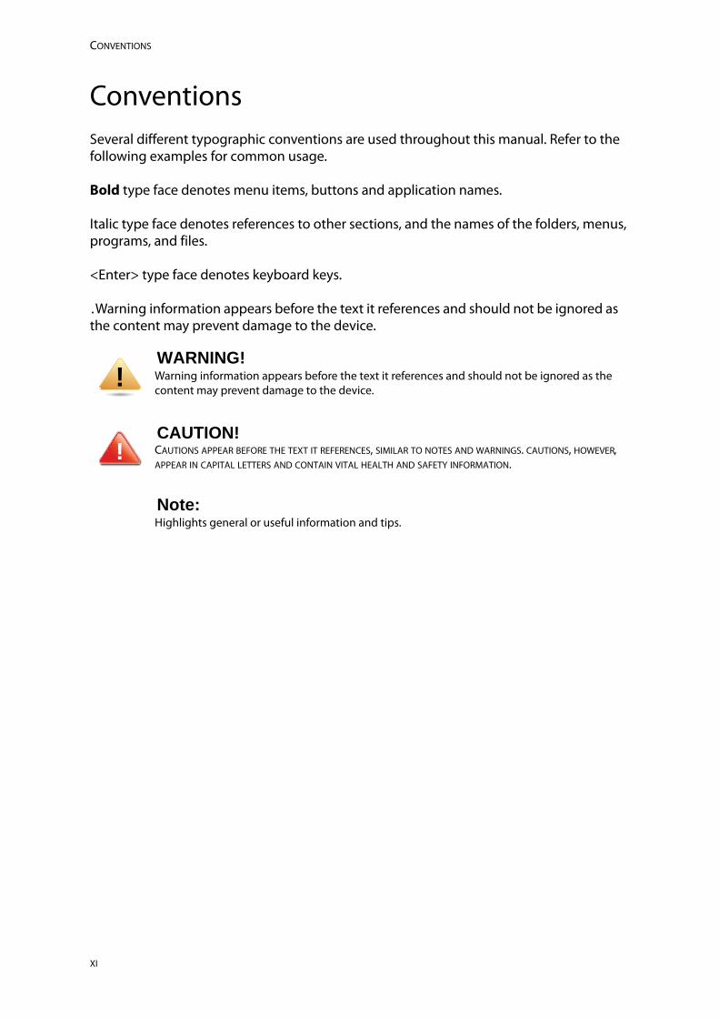
ConventionsSeveral different typographic conventions are used throughout this manual. Refer to the following examples for common usage.
Bold type face denotes menu items, buttons and application names.
Italic type face denotes references to other sections, and the names of the folders, menus, programs, and files.
<Enter> type face denotes keyboard keys.
.Warning information appears before the text it references and should not be ignored as the content may prevent damage to the device.
WARNING!Warning information appears before the text it references and should not be ignored as the content may prevent damage to the device.
CAUTION!CAUTIONS APPEAR BEFORE THE TEXT IT REFERENCES, SIMILAR TO NOTES AND WARNINGS. CAUTIONS, HOWEVER, APPEAR IN CAPITAL LETTERS AND CONTAIN VITAL HEALTH AND SAFETY INFORMATION.
Note:Highlights general or useful information and tips.
!
!
PRECAUTIONARY MEASURES
Precautionary MeasuresRead all caution and safety statements in this document before performing any of the instructions. To reduce the risk of bodily injury, electrical shock, fire, and equipment dam-age, read and observe all warnings and precautions in this chapter before installing or maintaining your system. To avoid personal injury or property damage, before you begin installing the product, read, observe, and adhere to all of the following instructions and information. The following symbols may be used throughout this guide and may be marked on the product and / or the product packaging.
Safety Instructions about your system
In the event of a conflict between the information in this guide and information provided with the product or on the website for a particular product, the product documentation takes precedence.
Your system should be integrated and serviced only by technically qualified persons.
You must adhere to the guidelines in this guide and the assembly instructions in related chapters to ensure and maintain compliance with existing product certifications and approvals. Use only the described, regulated components specified in this guide. Use of other products / components will void the UL Listing and other regulatory approvals of the product, and may result in noncompliance with product regulations in the region(s) in which the product is sold.
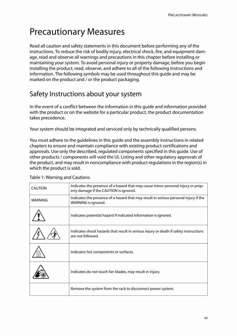
Table 1: Warning and Cautions
CAUTIONIndicates the presence of a hazard that may cause minor personal injury or prop-erty damage if the CAUTION is ignored.
WARNINGIndicates the presence of a hazard that may result in serious personal injury if the WARNING is ignored.
Indicates potential hazard if indicated information is ignored.
Indicates shock hazards that result in serious injury or death if safety instructions are not followed.
Indicates hot components or surfaces.
Indicates do not touch fan blades, may result in injury.
Remove the system from the rack to disconnect power system.
XII
PRECAUTIONARY MEASURES
Intended Application Uses
This product was evaluated as Information Technology Equipment (ITE), which may be installed in offices, schools, computer rooms, and similar commercial type locations. The suitability of this product for other product categories and environments (such as medical, industrial, residential, alarm systems, and test equipment), other than an ITE application, may require further evaluation.
Site Selection
The system is designed to operate in a typical office environment. Choose a site that is:
Clean, dry, and free of airborne particles (other than normal room dust).
Well-ventilated and away from sources of heat including direct sunlight and radia-tors.
Away from sources of vibration or physical shock.
Isolated from strong electromagnetic fields produced by electrical devices.
In regions that are susceptible to electrical storms, we recommend you plug your system into a surge suppressor and disconnect telecommunication lines to your modem during an electrical storm.
Provided with a properly grounded wall outlet.
Provided with sufficient space to access the power system, because they serve as the product's main power disconnect.
Provided with either two independent DC power system or two independent phases from a single power system.
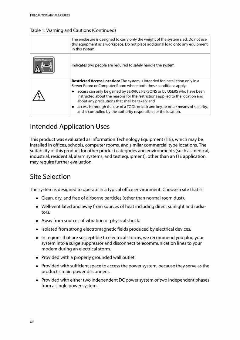
The enclosure is designed to carry only the weight of the system sled. Do not use this equipment as a workspace. Do not place additional load onto any equipment in this system.
Indicates two people are required to safely handle the system.
Restricted Access Location: The system is intended for installation only in a Server Room or Computer Room where both these conditions apply: access can only be gained by SERVICE PERSONS or by USERS who have been
instructed about the reasons for the restrictions applied to the location and about any precautions that shall be taken; and
access is through the use of a TOOL or lock and key, or other means of security, and is controlled by the authority responsible for the location.
Table 1: Warning and Cautions (Continued)
XIII
PRECAUTIONARY MEASURES
Equipment Handling Practices
Reduce the risk of personal injury or equipment damage:
Conform to local occupational health and safety requirements when moving and lifting equipment.
Use mechanical assistance or other suitable assistance when moving and lifting equipment.
To reduce the weight for easier handling, remove any easily detachable compo-nents.
Never lift or move your system soley by the handle on the component.
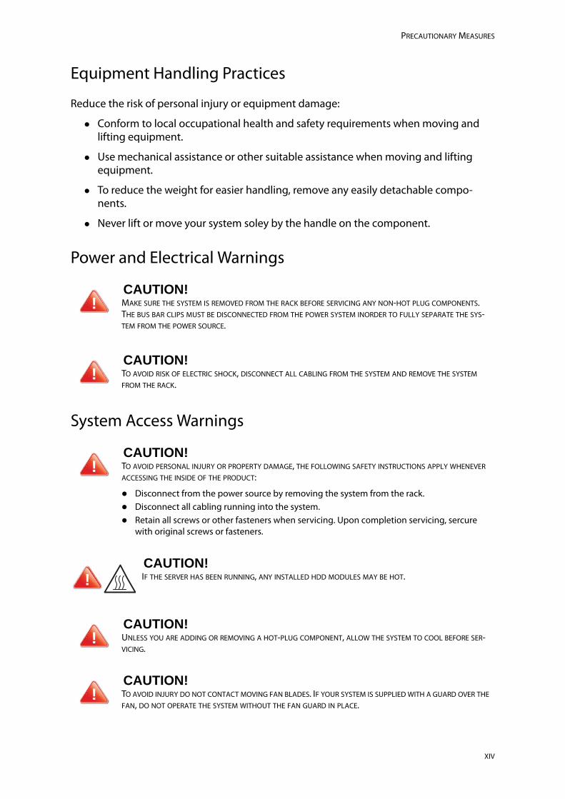
Power and Electrical Warnings
System Access Warnings
CAUTION!MAKE SURE THE SYSTEM IS REMOVED FROM THE RACK BEFORE SERVICING ANY NON-HOT PLUG COMPONENTS. THE BUS BAR CLIPS MUST BE DISCONNECTED FROM THE POWER SYSTEM INORDER TO FULLY SEPARATE THE SYS-TEM FROM THE POWER SOURCE.
CAUTION!TO AVOID RISK OF ELECTRIC SHOCK, DISCONNECT ALL CABLING FROM THE SYSTEM AND REMOVE THE SYSTEM FROM THE RACK.
CAUTION!TO AVOID PERSONAL INJURY OR PROPERTY DAMAGE, THE FOLLOWING SAFETY INSTRUCTIONS APPLY WHENEVER ACCESSING THE INSIDE OF THE PRODUCT:
Disconnect from the power source by removing the system from the rack. Disconnect all cabling running into the system. Retain all screws or other fasteners when servicing. Upon completion servicing, sercure
with original screws or fasteners.
CAUTION!IF THE SERVER HAS BEEN RUNNING, ANY INSTALLED HDD MODULES MAY BE HOT.
CAUTION!UNLESS YOU ARE ADDING OR REMOVING A HOT-PLUG COMPONENT, ALLOW THE SYSTEM TO COOL BEFORE SER-VICING.
CAUTION!TO AVOID INJURY DO NOT CONTACT MOVING FAN BLADES. IF YOUR SYSTEM IS SUPPLIED WITH A GUARD OVER THE FAN, DO NOT OPERATE THE SYSTEM WITHOUT THE FAN GUARD IN PLACE.
!
!
!
!
!
!
XIV

PRECAUTIONARY MEASURES
Rack Mount Warnings
The following installation guidelines are required by UL for maintaining safety compliance when installing your system into a rack.
The equipment rack must be anchored to an unmovable support to prevent it from tip-ping when your system or piece of equipment is extended from it. The equipment rack must be installed according to the rack manufacturer's instructions.
Install equipment in the rack from the bottom up, with the heaviest equipment at the bot-tom of the rack.
Extend only one piece of equipment from the rack at a time.
You are responsible for installing a main power disconnect for the entire rack unit. This main disconnect must be readily accessible, and it must be labeled as controlling power to the entire unit, not just to the system(s).
To avoid risk of potential electric shock, a proper safety ground must be implemented for the rack and each piece of equipment installed in it.
Elevated Operating Ambient - If installed in a closed or multi-unit rack assembly, the oper-ating ambient temperature of the rack environment may be greater than room ambient. Therefore, consideration should be given to installing the equipment in an environment compatible with the maximum ambient temperature (Tma) specified by the manufac-turer.
Reduced Air Flow - Installation of the equipment in a rack should be such that the amount of air flow required for safe operation of the equipment is not compromised.
Mechanical Loading - Mounting of the equipment in the rack should be such that a haz-ardous condition is not achieved due to uneven mechanical loading.
Circuit Overloading - Consideration should be given to the connection of the equipment to the supply circuit and the effect that overloading of the circuits might have on over-cur-rent protection and supply wiring. Appropriate consideration of equipment nameplate ratings should be used when addressing this concern.
Reliable Earthing - Reliable earthing of rack-mounted equipment should be maintained.
Particular attention should be given to supply connections other than direct connections to the branch circuit (e.g. use of power strips).
XV
PRECAUTIONARY MEASURES
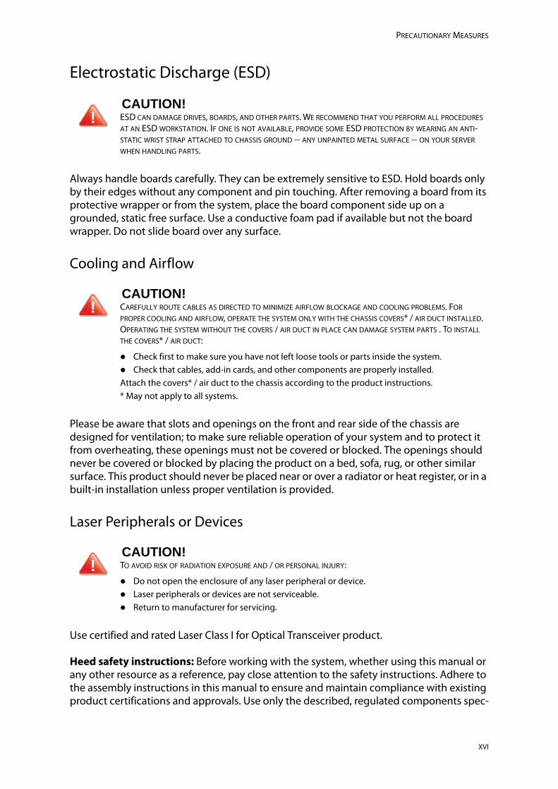
Electrostatic Discharge (ESD)
Always handle boards carefully. They can be extremely sensitive to ESD. Hold boards only by their edges without any component and pin touching. After removing a board from its protective wrapper or from the system, place the board component side up on a grounded, static free surface. Use a conductive foam pad if available but not the board wrapper. Do not slide board over any surface.
Cooling and Airflow
Please be aware that slots and openings on the front and rear side of the chassis are designed for ventilation; to make sure reliable operation of your system and to protect it from overheating, these openings must not be covered or blocked. The openings should never be covered or blocked by placing the product on a bed, sofa, rug, or other similar surface. This product should never be placed near or over a radiator or heat register, or in a built-in installation unless proper ventilation is provided.
Laser Peripherals or Devices
Use certified and rated Laser Class I for Optical Transceiver product.
Heed safety instructions: Before working with the system, whether using this manual or any other resource as a reference, pay close attention to the safety instructions. Adhere to the assembly instructions in this manual to ensure and maintain compliance with existing product certifications and approvals. Use only the described, regulated components spec-
CAUTION!ESD CAN DAMAGE DRIVES, BOARDS, AND OTHER PARTS. WE RECOMMEND THAT YOU PERFORM ALL PROCEDURES AT AN ESD WORKSTATION. IF ONE IS NOT AVAILABLE, PROVIDE SOME ESD PROTECTION BY WEARING AN ANTI-STATIC WRIST STRAP ATTACHED TO CHASSIS GROUND -- ANY UNPAINTED METAL SURFACE -- ON YOUR SERVER WHEN HANDLING PARTS.
CAUTION!CAREFULLY ROUTE CABLES AS DIRECTED TO MINIMIZE AIRFLOW BLOCKAGE AND COOLING PROBLEMS. FOR PROPER COOLING AND AIRFLOW, OPERATE THE SYSTEM ONLY WITH THE CHASSIS COVERS* / AIR DUCT INSTALLED. OPERATING THE SYSTEM WITHOUT THE COVERS / AIR DUCT IN PLACE CAN DAMAGE SYSTEM PARTS . TO INSTALL THE COVERS* / AIR DUCT:
Check first to make sure you have not left loose tools or parts inside the system. Check that cables, add-in cards, and other components are properly installed.Attach the covers* / air duct to the chassis according to the product instructions. * May not apply to all systems.
CAUTION!TO AVOID RISK OF RADIATION EXPOSURE AND / OR PERSONAL INJURY:
Do not open the enclosure of any laser peripheral or device. Laser peripherals or devices are not serviceable. Return to manufacturer for servicing.
!
!
!
XVI
PRECAUTIONARY MEASURES
ified in this manual. Use of other products / components will void the UL listing and other regulatory approvals of the product and will most likely result in non-compliance with product regulations in the region(s) in which the product is sold.
System power on/off: To remove power from system, you must remove the system from rack. Make sure the system is removed from the rack before opening the chassis, adding, or removing any non hot-plug components.
Hazardous conditions, devices and cables: Hazardous electrical conditions may be present on power, telephone, and communication cables. Turn off the system and discon-nect the cables attached to the system before opening it. Otherwise, personal injury or equipment damage can result.
Electrostatic discharge (ESD) and ESD protection: ESD can damage drives, boards, and other parts. We recommend that you perform all procedures in this chapter only at an ESD workstation. If one is not available, provide some ESD protection by wearing an antistatic wrist strap attached to chassis ground any unpainted metal surface on the server when handling parts.
ESD and handling boards: Always handle boards carefully. They can be extremely sensi-tive to electrostatic discharge (ESD). Hold boards only by their edges. After removing a board from its protective wrapper or from the server, place the board component side up on a grounded, static free surface. Use a conductive foam pad if available but not the board wrapper. Do not slide board over any surface.
Installing or removing jumpers: A jumper is a small plastic encased conductor that slips over two jumper pins. Some jumpers have a small tab on top that can be gripped with fin-gertips or with a pair of fine needle nosed pliers. If the jumpers do not have such a tab, take care when using needle nosed pliers to remove or install a jumper; grip the narrow sides of the jumper with the pliers, never the wide sides. Gripping the wide sides can dam-age the contacts inside the jumper, causing intermittent problems with the function con-trolled by that jumper. Take care to grip with, but not squeeze, the pliers or other tool used to remove a jumper, or the pins on the board may bend or break.
General Information
The information about rack and the wording “rack” in this technical guide supports the organization of Open Compute definition.
The term Rack as found in this technical guide referes to the term Rack or Open Rack as described and used in the Open Compute Project definition.
Before servicing this system, it is recommened to read this technical guide completely to be aware of any safety issues or requirements involved in the servicing of this system.
XVII
PRECAUTIONARY MEASURES
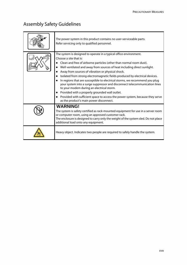
Assembly Safety Guidelines
The power system in this product contains no user-serviceable parts.Refer servicing only to qualified personnel.
The system is designed to operate in a typical office environment.Choose a site that is: Clean and free of airborne particles (other than normal room dust). Well ventilated and away from sources of heat including direct sunlight. Away from sources of vibration or physical shock. Isolated from strong electromagnetic fields produced by electrical devices. In regions that are susceptible to electrical storms, we recommend you plug
your system into a surge suppressor and disconnect telecommunication lines to your modem during an electrical storm.
Provided with a properly grounded wall outlet. Provided with sufficient space to access the power system, because they serve
as the product's main power disconnect.
WARNING!The system is safety certified as rack-mounted equipment for use in a server room or computer room, using an approved customer rack.The enclosure is designed to carry only the weight of the system sled. Do not place additional load onto any equipment.
Heavy object. Indicates two people are required to safely handle the system.
XVIII

About the SystemChapter 1
This section introduces the system, its different configuration(s) and the main features.
INTRODUCTION ABOUT THE SYSTEM
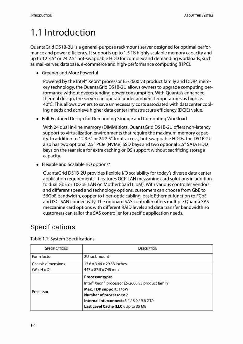
1.1 IntroductionQuantaGrid D51B-2U is a general-purpose rackmount server designed for optimal perfor-mance and power efficiency. It supports up to 1.5 TB highly scalable memory capacity and up to 12 3.5” or 24 2.5” hot-swappable HDD for complex and demanding workloads, such as mail-server, database, e-commerce and high-performance computing (HPC).
Greener and More Powerful
Powered by the Intel® Xeon® processor E5-2600 v3 product family and DDR4 mem-ory technology, the QuantaGrid D51B-2U allows owners to upgrade computing per-formance without overextending power consumption. With Quanta’s enhanced thermal design, the server can operate under ambient temperatures as high as 40°C. This allows owners to save unnecessary costs associated with datacenter cool-ing needs and achieve higher data center infrastructure efficiency (DCIE) value.
Full-Featured Design for Demanding Storage and Computing Workload
With 24 dual in-line memory (DIMM) slots, QuantaGrid D51B-2U offers non-latency support to virtualization environments that require the maximum memory capac-ity. In addition to 12 3.5” or 24 2.5” front-access, hot-swappable HDDs, the D51B-2U also has two optional 2.5” PCIe (NVMe) SSD bays and two optional 2.5” SATA HDD bays on the rear side for extra caching or OS support without sacrificing storage capacity.
Flexible and Scalable I/O options*
QuantaGrid D51B-2U provides flexible I/O scalability for today’s diverse data center application requirements. It features OCP LAN mezzanine card solutions in addition to dual GbE or 10GbE LAN on Motherboard (LoM). With various controller vendors and different speed and technology options, customers can choose from GbE to 56GbE bandwidth, copper to fiber-optic cabling, basic Ethernet function to FCoE and ISCI SAN connectivity. The onboard SAS controller offers multiple Quanta SAS mezzanine card options with different RAID levels and data transfer bandwidth so customers can tailor the SAS controller for specific application needs.
Specifications
Table 1.1: System Specifications
SPECIFICATIONS DESCRIPTION
Form factor 2U rack mount
Chassis dimensions(W x H x D)
17.6 x 3.44 x 29.33 inches447 x 87.5 x 745 mm
Processor
Processor type:Intel® Xeon® processor E5-2600 v3 product familyMax. TDP support: 145WNumber of processors: 2Internal Interconnect: 6.4 / 8.0 / 9.6 GT/sLast Level Cache (LLC): Up to 35 MB
1-1
ABOUT THE SYSTEM INTRODUCTION
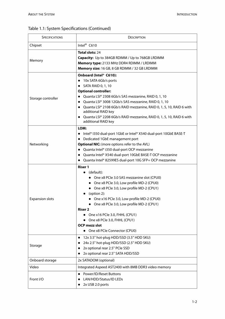
Chipset Intel® C610
Memory
Total slots: 24Capacity: Up to 384GB RDIMM / Up to 768GB LRDIMMMemory type: 2133 MHz DDR4 RDIMM / LRDIMMMemory size: 16 GB, 8 GB RDIMM / 32 GB LRDIMM
Storage controller
Onboard (Intel® C610): 10x SATA 6Gb/s ports SATA RAID 0, 1, 10Optional controller: Quanta LSI® 2308 6Gb/s SAS mezzanine, RAID 0, 1, 10 Quanta LSI® 3008 12Gb/s SAS mezzanine, RAID 0, 1, 10 Quanta LSI® 2108 6Gb/s RAID mezzanine, RAID 0, 1, 5, 10, RAID 6 with
additional RAID key Quanta LSI® 2208 6Gb/s RAID mezzanine, RAID 0, 1, 5, 10, RAID 6 with
additional RAID key
Networking
LOM: Intel® I350 dual-port 1GbE or Intel® X540 dual-port 10GbE BASE-T Dedicated 1GbE management portOptional NIC: (more options refer to the AVL) Quanta Intel® i350 dual-port OCP mezzanine Quanta Intel® X540 dual-port 10GbE BASE-T OCP mezzanine Quanta Intel® 82599ES dual-port 10G SFP+ OCP mezzanine
Expansion slots
Riser 1 (default): One x8 PCIe 3.0 SAS mezzanine slot (CPU0) One x8 PCIe 3.0, Low profile MD-2 (CPU0) One x8 PCIe 3.0, Low profile MD-2 (CPU1)
(option 2): One x16 PCIe 3.0, Low profile MD-2 (CPU0) One x8 PCIe 3.0, Low profile MD-2 (CPU1)
Riser 2 One x16 PCIe 3.0, FHHL (CPU1) One x8 PCIe 3.0, FHHL (CPU1)
OCP mezz slot One x8 PCIe Connector (CPU0)
Storage
12x 3.5" hot-plug HDD/SSD (3.5” HDD SKU) 24x 2.5" hot-plug HDD/SSD (2.5” HDD SKU) 2x optional rear 2.5" PCIe SSD 2x optional rear 2.5" SATA HDD/SSD
Onboard storage 2x SATADOM (optional)
Video Integrated Aspeed AST2400 with 8MB DDR3 video memory
Front I/O Power/ID/Reset Buttons LAN/HDD/Status/ID LEDs 2x USB 2.0 ports
Table 1.1: System Specifications (Continued)
SPECIFICATIONS DESCRIPTION
1-2
INTRODUCTION ABOUT THE SYSTEM
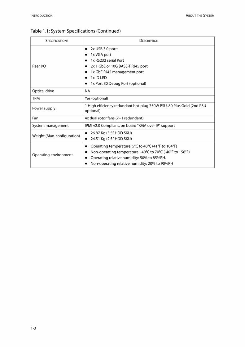
Rear I/O
2x USB 3.0 ports 1x VGA port 1x RS232 serial Port 2x 1 GbE or 10G BASE-T RJ45 port 1x GbE RJ45 management port 1x ID LED 1x Port 80 Debug Port (optional)
Optical drive NA
TPM Yes (optional)
Power supply1 High efficiency redundant hot-plug 750W PSU, 80 Plus Gold (2nd PSU optional)
Fan 4x dual rotor fans (7+1 redundant)
System management IPMI v2.0 Compliant, on board "KVM over IP" support
Weight (Max. configuration) 26.87 Kg (3.5” HDD SKU) 24.51 Kg (2.5” HDD SKU)
Operating environment
Operating temperature: 5°C to 40°C (41°F to 104°F) Non-operating temperature: -40°C to 70°C (-40°F to 158°F) Operating relative humidity: 50% to 85%RH. Non-operating relative humidity: 20% to 90%RH
Table 1.1: System Specifications (Continued)
SPECIFICATIONS DESCRIPTION
1-3
ABOUT YOUR SYSTEM PACKAGE CONTENTS
1-4
1.2 Package Contents (1) D51B-2U system
(2) processor heat sinks
(1) power supply unit
(1) power cord (optional)
(1) utility CD (Technical Guide included)
(1) rail kit
Note:For exact shipping contents, contact your Quanta sales representative.
A TOUR OF THE SYSTEM ABOUT THE SYSTEM
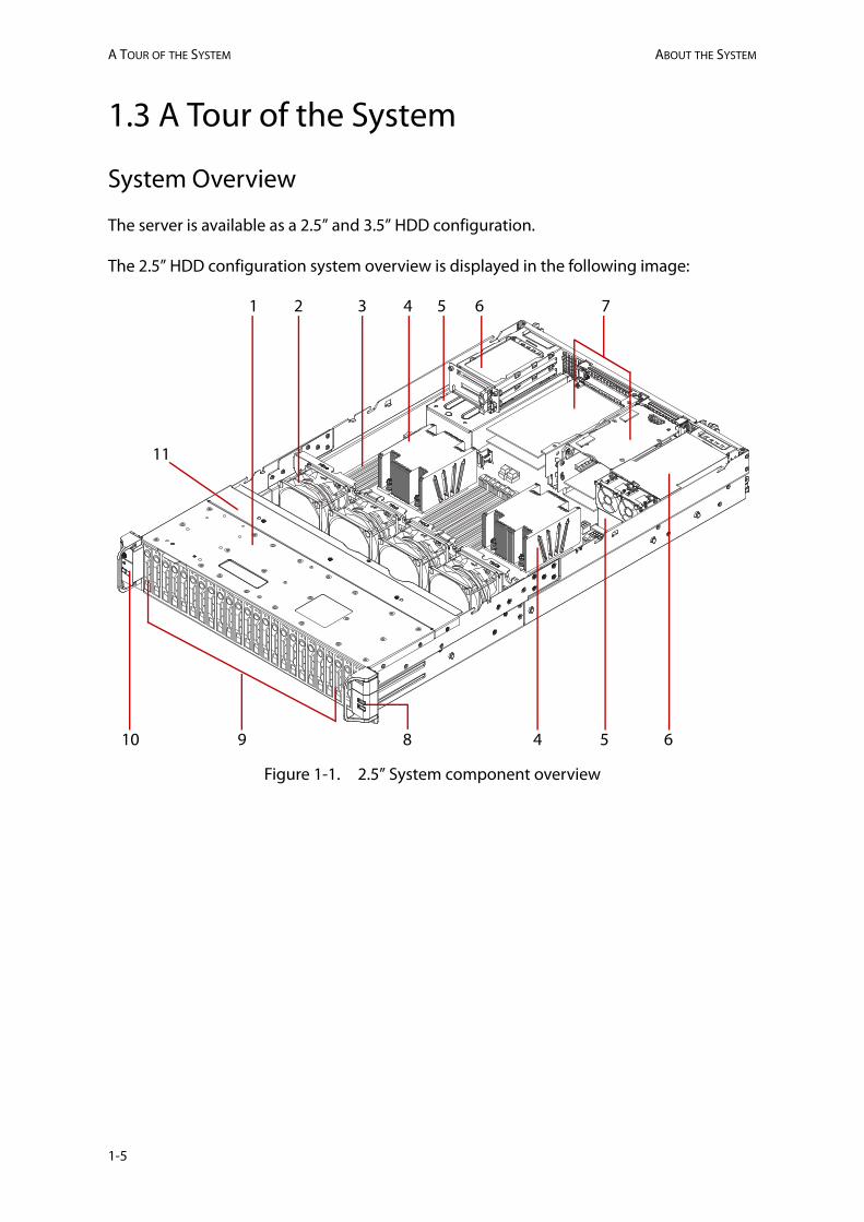
1.3 A Tour of the System
System Overview
The server is available as a 2.5” and 3.5” HDD configuration.
The 2.5” HDD configuration system overview is displayed in the following image:
Figure 1-1. 2.5” System component overview
321 4
8910
5
54
6
6
11
7
1-5
ABOUT THE SYSTEM SYSTEM OVERVIEW
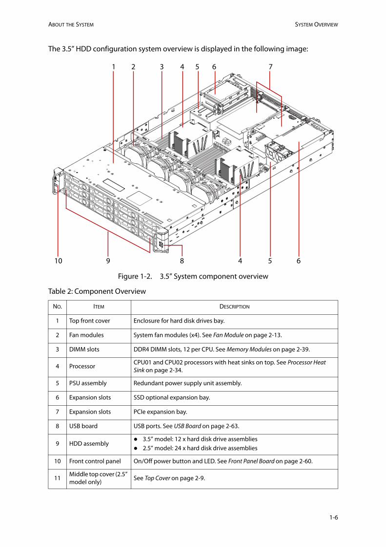
The 3.5” HDD configuration system overview is displayed in the following image:
Figure 1-2. 3.5” System component overview
Table 2: Component Overview
NO. ITEM DESCRIPTION
1 Top front cover Enclosure for hard disk drives bay.
2 Fan modules System fan modules (x4). See Fan Module on page 2-13.
3 DIMM slots DDR4 DIMM slots, 12 per CPU. See Memory Modules on page 2-39.
4 ProcessorCPU01 and CPU02 processors with heat sinks on top. See Processor Heat Sink on page 2-34.
5 PSU assembly Redundant power supply unit assembly.
6 Expansion slots SSD optional expansion bay.
7 Expansion slots PCIe expansion bay.
8 USB board USB ports. See USB Board on page 2-63.
9 HDD assembly 3.5” model: 12 x hard disk drive assemblies 2.5” model: 24 x hard disk drive assemblies
10 Front control panel On/Off power button and LED. See Front Panel Board on page 2-60.
11Middle top cover (2.5” model only)
See Top Cover on page 2-9.
321 74
8910
5
54
6
6
1-6

SYSTEM OVERVIEW ABOUT THE SYSTEM
System Front View
Figure 1-3. 2.5” System front view
Figure 1-4. 3.5” System front view
Table 3: Front Panel View
NO. NAME DESCRIPTION
1 Front control panel On/Off power button and LED.
2 HDD bays 12 x 3.5” HDDs 24 x 2.5” HDDs
3 USB board USB 2.0 ports x 2. Front panel USB port.
1 2 3
1 2 3
1-7

ABOUT THE SYSTEM SYSTEM OVERVIEW
Front Control Panel
Figure 1-5. Front Control Panel
Table 4: Front Control Panel Definition
NO. ICON NAME DESCRIPTION
1Power button with LED
Power on / off
2 Reset button Soft reset system function
3 ID button Activates identification event
4 Fault LED Provides critical and non-critical failure notification
5HDD access LED
Hard disk drive access
6 LAN1 LED LAN access
7 LAN2 LED LAN access
8 ID LED Displays when ID button is pressed
1
2
3 876
54
1-8
SYSTEM OVERVIEW ABOUT THE SYSTEM
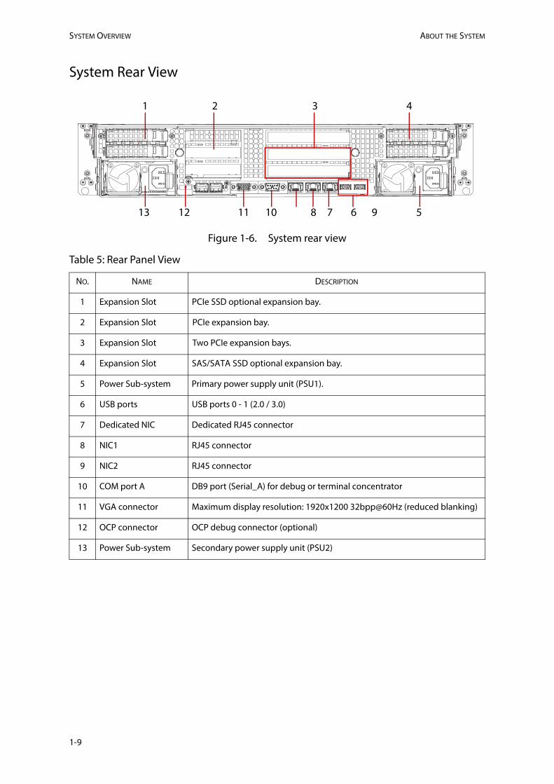
System Rear View
Figure 1-6. System rear view
Table 5: Rear Panel View
NO. NAME DESCRIPTION
1 Expansion Slot PCIe SSD optional expansion bay.
2 Expansion Slot PCIe expansion bay.
3 Expansion Slot Two PCIe expansion bays.
4 Expansion Slot SAS/SATA SSD optional expansion bay.
5 Power Sub-system Primary power supply unit (PSU1).
6 USB ports USB ports 0 - 1 (2.0 / 3.0)
7 Dedicated NIC Dedicated RJ45 connector
8 NIC1 RJ45 connector
9 NIC2 RJ45 connector
10 COM port A DB9 port (Serial_A) for debug or terminal concentrator
11 VGA connector Maximum display resolution: 1920x1200 32bpp@60Hz (reduced blanking)
12 OCP connector OCP debug connector (optional)
13 Power Sub-system Secondary power supply unit (PSU2)
13 8 5
4321
611 10 7 912
1-9
ABOUT THE SYSTEM LED DEFINITIONS
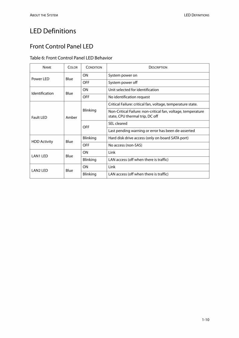
LED Definitions
Front Control Panel LED
Table 6: Front Control Panel LED Behavior
NAME COLOR CONDITION DESCRIPTION
Power LED BlueON System power on
OFF System power off
Identification BlueON Unit selected for identification
OFF No identification request
Fault LED Amber
Blinking
Critical Failure: critical fan, voltage, temperature state.
Non-Critical Failure: non-critical fan, voltage, temperature state, CPU thermal trip, DC off
OFFSEL cleared
Last pending warning or error has been de-asserted
HDD Activity BlueBlinking Hard disk drive access (only on board SATA port)
OFF No access (non-SAS)
LAN1 LED BlueON Link
Blinking LAN access (off when there is traffic)
LAN2 LED BlueON Link
Blinking LAN access (off when there is traffic)
1-10
LED DEFINITIONS ABOUT THE SYSTEM
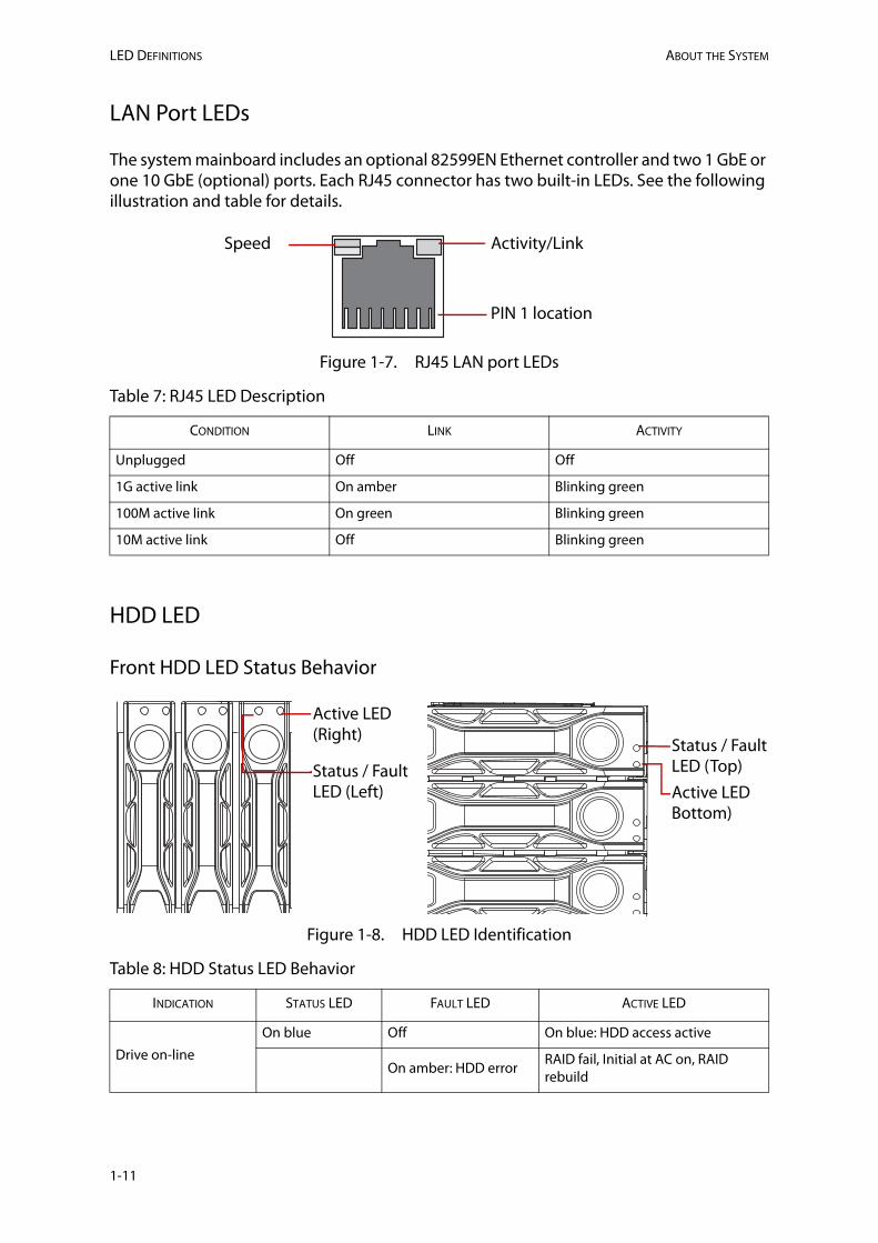
LAN Port LEDs
The system mainboard includes an optional 82599EN Ethernet controller and two 1 GbE or one 10 GbE (optional) ports. Each RJ45 connector has two built-in LEDs. See the following illustration and table for details.
Figure 1-7. RJ45 LAN port LEDs
HDD LED
Front HDD LED Status Behavior
Figure 1-8. HDD LED Identification
Table 7: RJ45 LED Description
CONDITION LINK ACTIVITY
Unplugged Off Off
1G active link On amber Blinking green
100M active link On green Blinking green
10M active link Off Blinking green
Table 8: HDD Status LED Behavior
INDICATION STATUS LED FAULT LED ACTIVE LED
Drive on-line
On blue Off On blue: HDD access active
On amber: HDD errorRAID fail, Initial at AC on, RAID rebuild
Speed Activity/Link
PIN 1 location
Active LED (Right)
Status / Fault LED (Left)
Status / Fault LED (Top)Active LED Bottom)
1-11
ABOUT THE SYSTEM LED DEFINITIONS
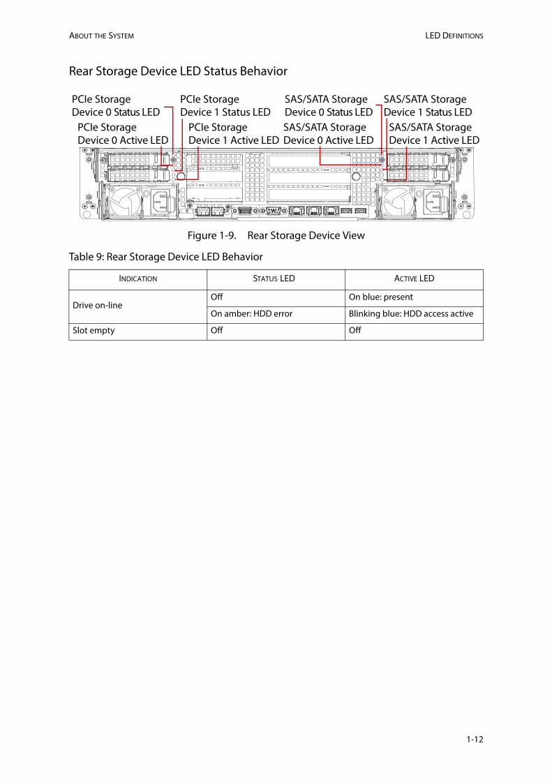
Rear Storage Device LED Status Behavior
Figure 1-9. Rear Storage Device View
Table 9: Rear Storage Device LED Behavior
INDICATION STATUS ADEL CTIVE LED
Drive on-linetneserp :eulb nOffO
On amber: HDD error Blinking blue: HDD access active
ffOffOytpme tolS
PCIe Storage Device 0 Active LED
PCIe Storage Device 1 Active LED
SAS/SATA Storage Device 0 Active LED
SAS/SATA Storage Device 1 Active LED
PCIe Storage Device 0 Status LED
PCIe Storage Device 1 Status LED
SAS/SATA Storage Device 0 Status LED
SAS/SATA Storage Device 1 Status LED
1-12

This page left blank intentionally.
Regulatory and Compliance InformationChapter2
This section provides regulatory and compliance information applicable to this system.

ELECTROMAGNETIC COMPATIBILITY NOTICES REGULATORY AND COMPLIANCE INFORMATION
2.1 Electromagnetic Compatibility Notices
FCC Verification Statement (USA)
This device complies with Part 15 of the FCC Rules. Operation is subject to the following two conditions: (1) this device may not cause harmful interference, and (2) this device must accept any interference received, including interference that may cause undesired operation.
This equipment has been tested and found to comply with the limits for a Class A digital device, pursuant to Part 15 of the FCC Rules. These limits are designed to provide reason-able protection against harmful interference in a residential installation. This equipment generates, uses, and can radiate radio frequency energy and, if not installed and used in accordance with the instructions, may cause harmful interference to radio communica-tions. However, there is no guarantee that interference will not occur in a particular instal-lation. If this equipment does cause harmful interference to radio or television reception, which can be determined by turning the equipment off and on, the user is encouraged to try to correct the interference by one or more of the following measures:
Reorient or relocate the receiving antenna.
Increase the separation between the equipment and the receiver
Connect the equipment to an outlet on a circuit other than the one to which the receiver is connected.
Consult the dealer or an experienced radio/TV technician for help.
Any changes or modifications not expressly approved by the grantee of this device could void the user's authority to operate the equipment. The customer is responsible for ensur-ing compliance of the modified product.
Only peripherals (computer input/output devices, terminals, printers, etc.) that comply with FCC Class A or B limits may be attached to this computer product. Operation with noncompliant peripherals is likely to result in interference to radio and TV reception.
All cables used to connect to peripherals must be shielded and grounded. Operation with cables, connected to peripherals, that are not shielded and grounded may result in inter-ference to radio and TV reception.
Europe (CE Declaration of Conformity)
This product has been tested in accordance too, and complies with the Low Voltage Direc-tive (73/23/EEC) and EMC Directive (89/336/EEC). The product has been marked with the CE Mark to illustrate its compliance.
2-1
REGULATORY AND COMPLIANCE INFORMATION VCCI (JAPAN)
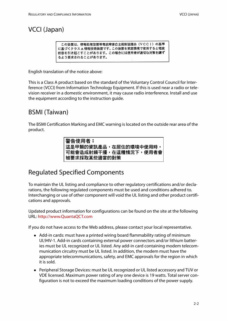
VCCI (Japan)
English translation of the notice above:
This is a Class A product based on the standard of the Voluntary Control Council for Inter-ference (VCCI) from Information Technology Equipment. If this is used near a radio or tele-vision receiver in a domestic environment, it may cause radio interference. Install and use the equipment according to the instruction guide.
BSMI (Taiwan)
The BSMI Certification Marking and EMC warning is located on the outside rear area of the product.
Regulated Specified Components
To maintain the UL listing and compliance to other regulatory certifications and/or decla-rations, the following regulated components must be used and conditions adhered to. Interchanging or use of other component will void the UL listing and other product certifi-cations and approvals.
Updated product information for configurations can be found on the site at the following URL: http://www.QuantaQCT.com
If you do not have access to the Web address, please contact your local representative.
Add-in cards: must have a printed wiring board flammability rating of minimum UL94V-1. Add-in cards containing external power connectors and/or lithium batter-ies must be UL recognized or UL listed. Any add-in card containing modem telecom-munication circuitry must be UL listed. In addition, the modem must have the appropriate telecommunications, safety, and EMC approvals for the region in which it is sold.
Peripheral Storage Devices: must be UL recognized or UL listed accessory and TUV or VDE licensed. Maximum power rating of any one device is 19 watts. Total server con-figuration is not to exceed the maximum loading conditions of the power supply.
2-2

RESTRICTION OF HAZARDOUS SUBSTANCES (ROHS) COMPLIANCE REGULATORY AND COMPLIANCE INFORMATION
Restriction of Hazardous Substances (RoHS) Compliance
Quanta® Computer Inc. has a system in place to restrict the use of banned substances in accordance with the European Directive 2002/95/EC. Compliance is based on declaration that materials banned in the RoHS Directive are either (1) below all applicable threshold limits or (2) an approved / pending RoHS exemption applies.
RoHS implementation details are not fully defined and may change.
Threshold limits and banned substances are noted below:
Quantity limit of 0.1% by mass (1000 PPM) for:
Lead
Mercury
Hexavalent Chromium
Polybrominated Biphenyls Diphenyl Ethers (PBDE)
Quantity limit of 0.01% by mass (100 PPM) for:
Cadmium
End of Life / Product Recycling
Product recycling and end-of-life take-back systems and requirements vary by country. Contact the retailer or distributor of this product for information about product recycling and / or take-back.
2-3
REGULATORY AND COMPLIANCE INFORMATION PRODUCT REGULATORY COMPLIANCE MARKINGS
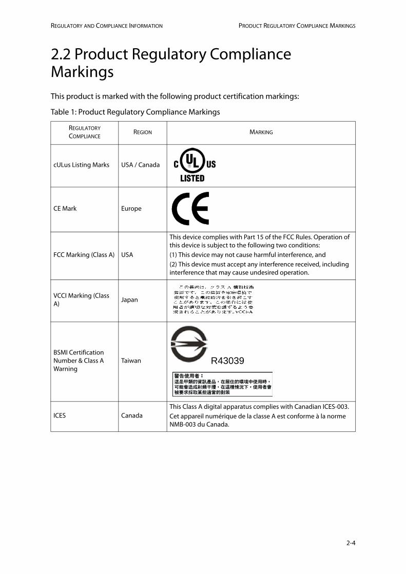
2.2 Product Regulatory Compliance MarkingsThis product is marked with the following product certification markings:
Table 1: Product Regulatory Compliance Markings
REGULATORY COMPLIANCE
REGION MARKING
cULus Listing Marks USA / Canada
CE Mark Europe
FCC Marking (Class A) USA
This device complies with Part 15 of the FCC Rules. Operation of this device is subject to the following two conditions:(1) This device may not cause harmful interference, and(2) This device must accept any interference received, including interference that may cause undesired operation.
VCCI Marking (Class A)
Japan
BSMI Certification Number & Class A Warning
Taiwan R43039
ICES CanadaThis Class A digital apparatus complies with Canadian ICES-003.Cet appareil numérique de la classe A est conforme à la norme NMB-003 du Canada.
2-4
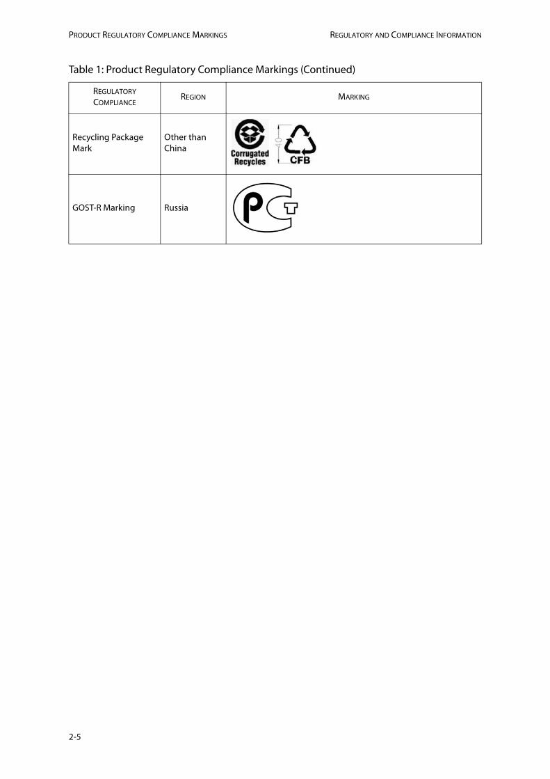
PRODUCT REGULATORY COMPLIANCE MARKINGS REGULATORY AND COMPLIANCE INFORMATION
Recycling Package Mark
Other than China
GOST-R Marking Russia
Table 1: Product Regulatory Compliance Markings (Continued)
REGULATORY COMPLIANCE
REGION MARKING
2-5