
S260-20-9 Types VR, VCR, VLR Maintenance Instructions · September 1983 New Issue Printed in USA...
28
September 1983 ● New Issue Printed in USA Oil Switches Types VR, VCR, VLR Maintenance Instructions 1 S260-20-9 Service Information Figure 1. Type VR,VCR and VLR electronically controlled three phase oil switch. These instructions do not claim to cover all details or variations in the equipment, procedure, or process described, nor to provide directions for meeting every contingency during installation, operation, or maintenance. When additional information is desired to satisfy a problem not covered sufficiently for the user’s purpose, please contact your Cooper Power Systems sales engineer. CAUTION: Do not energize this equipment out of oil. ! CONTENTS Introduction . . . . . . . . . . . . . . . . . 1 General Description . . . . . . . . . . 1 Description of Operation . . . . . . 3 Standard Actuator . . . . . . . . . . . . 3 Quick-Close Actuator . . . . . . . . . 4 Ratings and Specifications . . . . 5 Maintenance . . . . . . . . . . . . . . . . 5 Frequency of Maintenance . . . . . 5 Periodic Maintenance Inspection . 5 Operating Instructions . . . . . . . . 6 Electrical Operation . . . . . . . . . 6 Standard Actuator . . . . . . . . . 6 Quick-Close Actuator . . . . . . . 6 Manual Operation . . . . . . . . . 6 To Close Switch . . . . . . . . . 6 To open Switch . . . . . . . . . . 6 Oil Condition . . . . . . . . . . . . . . 6 Insulation Level Withstand Tests 6 Shop Repair Procedures . . . . . 7 Bushings . . . . . . . . . . . . . . . . . 7 Contacts . . . . . . . . . . . . . . . . . 7 Type VR and VCR Switches . 8 Type VLR Switches . . . . . . . . 11 Actuator Mechanism . . . . . . . . 13 Electrical Components . . . . . 13 Trip Solenoid . . . . . . . . . . . . 14 Motor Replacement . . . . . . . 15 Speed Reducer . . . . . . . . . . 15 Service Parts List ..................... 17 Tank and Head Assembly Parts (Figure 39) .......................... 18 Type VR Contact Assembly Parts (Figure 40) .......................... 20 Type VCR Contact Assembly Parts (Figure 41) .......................... 21 Type VLR Contact Assembly Parts (Figure 42) .......................... 22 Actuator Mechanism Parts (Figure 43) .......................... 24 Quick-Close Mechanism Parts (Figure 44) .......................... 26
Transcript of S260-20-9 Types VR, VCR, VLR Maintenance Instructions · September 1983 New Issue Printed in USA...

September 1983 ● New IssuePrinted in USA
Oil Switches
Types VR, VCR, VLRMaintenance Instructions
1
S260-20-9Service Information
Figure 1.Type VR,VCR and VLR electronically controlled three phase oil switch.
These instructions do not claim to cover all details or variations in the equipment, procedure, or process described, nor to providedirections for meeting every contingency during installation, operation, or maintenance. When additional information is desired tosatisfy a problem not covered sufficiently for the user’s purpose, please contact your Cooper Power Systems sales engineer.
CAUTION: Do not energize thisequipment out of oil.!
CONTENTSIntroduction . . . . . . . . . . . . . . . . . 1General Description . . . . . . . . . . 1Description of Operation . . . . . . 3
Standard Actuator . . . . . . . . . . . . 3Quick-Close Actuator . . . . . . . . . 4
Ratings and Specifications . . . . 5Maintenance . . . . . . . . . . . . . . . . 5
Frequency of Maintenance . . . . . 5Periodic Maintenance Inspection . 5Operating Instructions . . . . . . . . 6
Electrical Operation . . . . . . . . . 6Standard Actuator . . . . . . . . . 6Quick-Close Actuator . . . . . . . 6Manual Operation . . . . . . . . . 6
To Close Switch . . . . . . . . . 6To open Switch . . . . . . . . . . 6
Oil Condition . . . . . . . . . . . . . . 6Insulation Level Withstand Tests 6
Shop Repair Procedures . . . . . 7Bushings . . . . . . . . . . . . . . . . . 7Contacts . . . . . . . . . . . . . . . . . 7
Type VR and VCR Switches . 8Type VLR Switches . . . . . . . . 11
Actuator Mechanism . . . . . . . . 13Electrical Components . . . . . 13Trip Solenoid . . . . . . . . . . . . 14Motor Replacement . . . . . . . 15Speed Reducer . . . . . . . . . . 15
Service Parts List ..................... 17Tank and Head Assembly Parts
(Figure 39) .......................... 18Type VR Contact Assembly Parts
(Figure 40) .......................... 20Type VCR Contact Assembly Parts
(Figure 41) .......................... 21Type VLR Contact Assembly Parts
(Figure 42) .......................... 22Actuator Mechanism Parts
(Figure 43) .......................... 24Quick-Close Mechanism Parts
(Figure 44) .......................... 26

2
INTRODUCTlONService Information S260-20-9 coversthe maintenance instructions for TypesVR VCR, and VLR motor operated oilswitches. This includes their generaldescription, operating principles andinstructions for periodic inspection, test-ing, trouble shooting and shop repairs.A service parts list, keyed to explodedview drawings of the equipment isincluded at the back of the manual.NOTE: Maintenance instructions for early(pre1970) versions of these switches is cov-ered in the original service bulletin 287-10SB-1.
GENERAL DESCRIPTlONThese oil-filled, electrically-operateddevices provide, three-phase switchingfor general purpose loads (Type VR)capacitive loads (Type VCR) and induc-tive loads (Type VLR) on manual orautomatic command. These switchesutilize a common operating mechanismand package configuration, and are dif-ferentiated by their contact assemblies.
The Type VCR switch utilizes a set ofwedge-shaped moving contacts for arc-ing and a set of bayonet-type contactsfor load-carrying. In addition, resistors inseries with the arcing contacts dampboth the magnitude and frequency oftransient inrush currents for parallelcapacitor bank switching applications(Figure 2).
The Type VR switch utilizes two setsof wedge-shaped moving contacts, oneset for arcing and the second for load-carrying (Figure 3).
The Type VLR switch utilizes a set ofbayonet-type moving contacts whichoperate within self-blast interrupter-chambers for quick and effective arcinterruption when switching inductiveloads (Figure 4).
The contact structures for all threephases are linked with bell cranks to acommon torque shaft operated by theactuator mechanism located in the cabi-net on the front of the switch.
Figure 2.Untanked Type VCR switch.
Figure 3.Type VR contact arrangement.
Figure 4.Type VLR contact arrangement.
S260-20-9
3
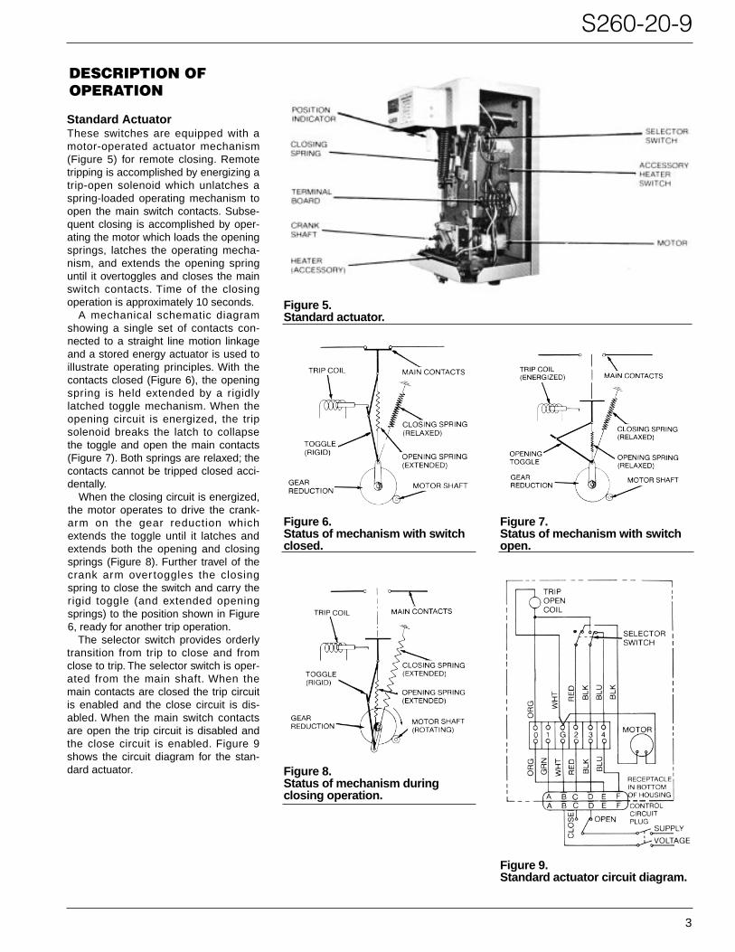
Figure 5.Standard actuator.
Figure 6.Status of mechanism with switchclosed.
Figure 8.Status of mechanism during closing operation.
Figure 9.Standard actuator circuit diagram.
Figure 7.Status of mechanism with switchopen.
DESCRIPTION OFOPERATION
Standard ActuatorThese switches are equipped with amotor-operated actuator mechanism(Figure 5) for remote closing. Remotetripping is accomplished by energizing atrip-open solenoid which unlatches aspring-loaded operating mechanism toopen the main switch contacts. Subse-quent closing is accomplished by oper-ating the motor which loads the openingsprings, latches the operating mecha-nism, and extends the opening springuntil it overtoggles and closes the mainswitch contacts. Time of the closingoperation is approximately 10 seconds.
A mechanical schematic diagramshowing a single set of contacts con-nected to a straight line motion linkageand a stored energy actuator is used toillustrate operating principles. With thecontacts closed (Figure 6), the openingspring is held extended by a rigidlylatched toggle mechanism. When theopening circuit is energized, the tripsolenoid breaks the latch to collapsethe toggle and open the main contacts(Figure 7). Both springs are relaxed; thecontacts cannot be tripped closed acci-dentally.
When the closing circuit is energized,the motor operates to drive the crank-arm on the gear reduction whichextends the toggle until it latches andextends both the opening and closingsprings (Figure 8). Further travel of thecrank arm over toggles the closingspring to close the switch and carry therigid toggle (and extended openingsprings) to the position shown in Figure6, ready for another trip operation.
The selector switch provides orderlytransition from trip to close and fromclose to trip. The selector switch is oper-ated from the main shaft. When themain contacts are closed the trip circuitis enabled and the close circuit is dis-abled. When the main switch contactsare open the trip circuit is disabled andthe close circuit is enabled. Figure 9shows the circuit diagram for the stan-dard actuator.
4
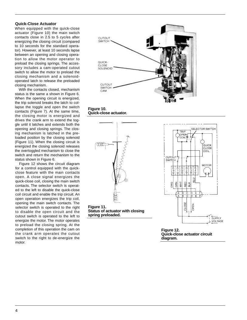
Figure 10.Quick-close actuator.
Figure 11.Status of actuator with closingspring preloaded.
Figure 12.Quick-close actuator circuit diagram.
Quick-Close ActuatorWhen equipped with the quick-closeactuator (Figure 10) the main switchcontacts close in 2.5 to 5 cyc/es afterenergizing the closing circuit (comparedto 10 seconds for the standard opera-tor). However, at least 10 seconds lapsebetween an opening and closing opera-tion to allow the motor operator topreload the closing springs. The acces-sory includes a cam-operated cutoutswitch to allow the motor to preload theclosing mechanism and a solenoid-operated latch to release the preloadedclosing mechanism.
With the contacts closed, mechanismstatus is the same a shown in Figure 6.When the opening circuit is energized,the trip solenoid breaks the latch to col-lapse the toggle and open the switchcontacts (Figure 7). At the same time,the closing motor is energized anddrives the crank arm to extend the tog-gle until it latches and extends both theopening and closing springs. The clos-ing mechanism is latched in the pre-loaded position by the closing solenoid(Figure 11). When the closing circuit isenergized the closing solenoid releasesthe overtoggled mechanism to close theswitch and return the mechanism to thestatus shown in Figure 6.
Figure 12 shows the circuit diagramfor a control equipped with the quick-close feature with the main contactsopen. A close signal energizes thequick-close coil, closing the main switchcontacts. The selector switch is operat-ed to the left to disable the quick-closecoil circuit and enable the trip circuit. Anopen operation energizes the trip coil,opening the main switch contacts. Theselector switch is operated to the rightto disable the open circuit and thecutout switch is operated to the left toenergize the motor. The motor operatesto preload the closing spring. At thecompletion of this operation the cam onthe crank arm operates the cutoutswitch to the right to de-energize themotor.

S260-20-9
5
Table 1Electrical Ratings
Table 2Load Switching Ratings
Table 3Short-Time Current Ratings
Table 4Actuator Operating Data
CAUTION: Never usevolatile solutions, detergents,
or water-soluble cleaners.
!
RATINGS AND SPECIFICATIONS
Rated maximum voltage (kv rms) 15.5Nominal system voltage (kv rms) 2.4-14.4Rated impulse withstand voltage
(BIL) (kv cress) 11060-Hz insulation level withstand (kv rms)
Dry, 1 minute 50Wet, 10 seconds 45
Rated continuous current (amps) 400
RatedSwitch Power CurrentType Application Factor (amps)
VR Capacitive currentswitching — 300
7.2 kv 14.4 kvInductive load 75-100 400 200switching 50-75 200 100
10-50 100 50VCR Capacitive current
switching* — 400VLR Inductive load
switching 10-100 400
Rated momentary asymmetrical current (amps) 20,000Rated 1/2-second symmetrical current (amps) 13,500Rated 1-second symmetrical current (amps) 10,000Rated 4-second symmetrical current (amps) 6,000Rated asymmetrical making current (amps) 20,000
Closing motor:Nominal operating voltage (vac) 120operating voltage range (vac) 95-130Inrush current (amps) 6Stead-state current (amps) 3Running time (see) 10Trip coil current at 120 vac (amps) 5
MAINTENANCEFrequency of MaintenanceBecause these switches are appliedunder widely varying operating and cli-matic conditions, maintenance intervalsare best determined by the user basedon actual operating experience. CooperPower Systems recommends the switchbe inspected and serviced yearly untilexperience indicates a more advanta-geous schedule. In no case should theservice interval extend beyond 1200operations.
Periodic MaintenanceInspectionEach periodic maintenance inspectionshould include at least the following:1. By-pass and remove the switch from
service.2. Inspect external components.
A. Clean the bushings and inspectfor chips, cracks and breaks.Replace as necessary. (Seepage 7 for procedure.)
B. Check for paint scratches andother mechanical damage. Paintto inhibit corrosion.
3. Perform a dielectric withstand test todetermine the insulation level. (Seepage 6 for procedure.)
4. Loosen the head bolts and removethe mechanism from the tank. Becareful not to damage the gasket, ifthe tank and head must be priedapart to break the seal.
5. Allow the oil to drain off the mech-anism.
6. Clean the internal components.A. Remove all traces of carbon by
wiping with a clean, lint-freecloth.
B. Flush the internal componentswith clean transformer oil.
7. Check the moving and stationarycontacts.A. Slight pitting and discoloration can
be dressed with crocus cloth or afine-tooth file.
B. Replace both the moving and sta-tionary contacts if they areseverely eroded. (See page 7 forprocedures.)NOTE: The contacts should bereplaced before erosion of the load-current transfer surfaces impairs theireffectiveness.
8. Manually close and trip the switchseveral times to check that all com-ponents perform properly. (See page6 for manual closing procedure.)
9. Inspect the tank wall liners. Soft orspongy areas indicate that water has

6
Figure 13.Manually cranking actuator toclose switch.
been absorbed. Replace liners ifthis condition is detected or evensuspected.
10. Check the dielectric strength of theinsulating oil.A. A sample taken near the bottom
of the tank should have adielectric strength of not lessthan 22 kv rms.
B. Low dielectric strength indicatesthe presence of water or carbondeposits; replace the oil. (SeeOil Condition.)
11. If oil must be replaced, drain thetank and discard the tank wall lin-ers.
12. Thoroughly clean out all sludge andcarbon deposits and rinse the tankwith clean oil.
13. Install new tank wall liners and fillthe tank with clean, new insulatingoil to within 1-1/4” of the top of thetank flange. Oil capacity is approxi-mately 19 gallons.NOTE: Use only new, or like new recon-ditioned transformer oil which conformsto the specifications in Cooper PowerSystems Reference Data R280 901, “OilSpecifications and Test”.
14. Clean and examine the head gas-ket. Replace if it is damaged or hastaken a permanent set.
15. Clean the head gasket seat andretank the switch.A. Replace the head bolts and
torque to 12-15 ft-lbs. Applyclamping force gradually andequally, in rotation, to each boltto achieve an evenly distributedgasket sealing pressure.NOTE: Maximum gap between tankflange and head casting shall be3/16 inch.
16. Check the oil level with the dipstickin the head and adjust the level tothe upper line on the stick.
17. Electrically operate the switch tocheck for proper operation.
18. Repeat the high voltage dielectricwithstand test (Step 3) to makesure the dielectric clearances with-in the tank have not been compro-mised.
Operating InstructionsELECTRICAL OPERATIONThe switch may be opened and closedelectrically by applying rated operatingvoltage directly to the terminal block ofthe actuator. See nameplate for ratedoperating voltage for the control.
Standard ActuatorRefer to the connection diagram for thestandard actuator (Figure 9) and pro-ceed as follows:
TO CLOSE SWITCH—Apply ratedoperating voltage across terminals 2and G long enough for the motor tocomplete its closing cycle (approximate-ly 10 seconds).
TO OPEN SWITCH—Momentar ilyapply rated operating voltage acrossterminals 3 and G to energize the tripsolenoid.
Quick-Close ActuatorRefer to the connection diagram for thequick-close actuator (Figure 12) andproceed as follows:
TO CLOSE SWITCH—Apply ratedoperating voltage across terminals 1and G. If the closing spr ing is notpreloaded, the motor will operate toextend the spring (approximately 10seconds). When closing spr ing ispreloaded, temporarily jumper terminals1 and 2 to energize the quickclosesolenoid.
TO OPEN SWITCH—Apply rated oper-ating voltage across terminals 3 and Gto energize the trip solenoid.
MANUAL OPERATIONA crank is included in the bottom of theactuator cabinet for closing the switchmanually.
To Close SwitchSTANDARD ACTUATOR—Apply crankto shaft on the front of the mechanism(Figure 13) and turn crank clockwiseuntil the closing spring overtoggles andcloses the switch (approximately 42turns).
QUICK CLOSE ACTUATOR — Applycrank to shaft on the front of the mecha-nism (Figure 13) and turn crank clock-wise until the closing spring drive crankhits its mechanical stop (approximately42 turns). Then mechanically operatethe quickclose solenoid to release thespring and close the switch.
To Open SwitchFor both the standard and quick-closeactuators, pull down the pull ring under-neath the actuator cabinet to mechani-cally operate the trip solenoid.
Oil ConditionOil plays an important role in the properfunctioning of the switch. It provides theinternal insulating barrier between phas-es and from phase to ground, and actsas an arc quencher. Switching opera-tions cause reductions of some of theoil into chemical compounds, free car-bon and gases. Some of these com-pounds form water-absorbing particleswhich reduce the dielectric strength ofthe oil. For effective switch operation theoil must be replaced before it deterio-rates below a safe level. OiI that hasbeen contaminated with carbon sludgeor has a dielectric strength of less than22 kv should be replaced.
Used oil must be reconditionedbefore using. Filtering may removeabsorbed and free water, and other con-taminants to raise the dielectric strengthto an acceptable level. However, it doesnot always remove water absorbingcontaminants. Thus, the dielectr icstrength of the oil may fall rapidly afterthe switch is returned to service. There-fore the switch should be filled with newoil or oil that has been restored to like-new condition. Oil used in these switch-es conforms to ASTM Standard D3487,Type l; its property limits are listed inReference Data R280-90-1; ”Oil Specifi-cations and Tests”.
New oil should always be filteredbefore using even though it is obtainedfrom an approved source. Passing oilthrough a blotter press will remove freewater and solid contaminants such asrust, dirt, and lint. When filtering the oil,aeration should be kept to a minimum toprevent moisture in the air from con-densing in the oil and lowering itsdielectric strength.
Insulation Level Withstand TestsHigh-potential withstand tests provideinformation regarding the dielectric con-dition of the switch. Testing is performedat 75% of the rated low-frequency with-stand voltage (37.5 kv). Proceed as fol-lows:
TEST 1: Proceed as follows:1. Close the switch.2. Ground switch tank and head.3. Connect together all three bushings
on one side of the switch.4. Apply test voltage (37.5 kv) to the
connected bushings.• The switch should withstand the
test voltage for 60 seconds.
S260-20-9
7
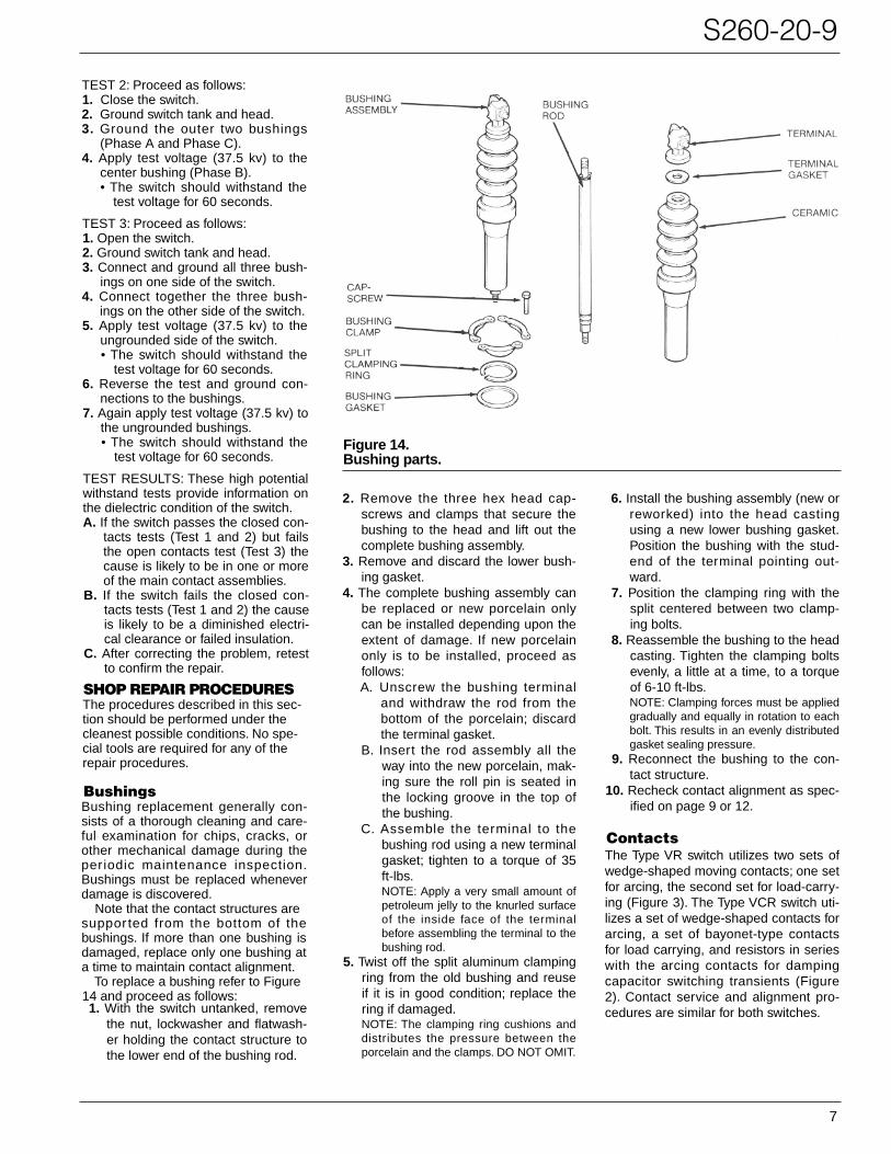
Figure 14.Bushing parts.
TEST 2: Proceed as follows:1. Close the switch.2. Ground switch tank and head.3. Ground the outer two bushings
(Phase A and Phase C).4. Apply test voltage (37.5 kv) to the
center bushing (Phase B).• The switch should withstand the
test voltage for 60 seconds.
TEST 3: Proceed as follows:1. Open the switch.2. Ground switch tank and head.3. Connect and ground all three bush-
ings on one side of the switch.4. Connect together the three bush-
ings on the other side of the switch.5. Apply test voltage (37.5 kv) to the
ungrounded side of the switch.• The switch should withstand the
test voltage for 60 seconds.6. Reverse the test and ground con-
nections to the bushings.7. Again apply test voltage (37.5 kv) to
the ungrounded bushings.• The switch should withstand the
test voltage for 60 seconds.
TEST RESULTS: These high potentialwithstand tests provide information onthe dielectric condition of the switch.A. If the switch passes the closed con-
tacts tests (Test 1 and 2) but failsthe open contacts test (Test 3) thecause is likely to be in one or moreof the main contact assemblies.
B. If the switch fails the closed con-tacts tests (Test 1 and 2) the causeis likely to be a diminished electri-cal clearance or failed insulation.
C. After correcting the problem, retestto confirm the repair.
SHOP REPAIR PROCEDURESThe procedures described in this sec-tion should be performed under thecleanest possible conditions. No spe-cial tools are required for any of therepair procedures.
BushingsBushing replacement generally con-sists of a thorough cleaning and care-ful examination for chips, cracks, orother mechanical damage during theperiodic maintenance inspection.Bushings must be replaced wheneverdamage is discovered.
Note that the contact structures aresuppor ted from the bottom of thebushings. If more than one bushing isdamaged, replace only one bushing ata time to maintain contact alignment.
To replace a bushing refer to Figure14 and proceed as follows:1. With the switch untanked, remove
the nut, lockwasher and flatwash-er holding the contact structure tothe lower end of the bushing rod.
2. Remove the three hex head cap-screws and clamps that secure thebushing to the head and lift out thecomplete bushing assembly.
3. Remove and discard the lower bush-ing gasket.
4. The complete bushing assembly canbe replaced or new porcelain onlycan be installed depending upon theextent of damage. If new porcelainonly is to be installed, proceed asfollows:A. Unscrew the bushing terminal
and withdraw the rod from thebottom of the porcelain; discardthe terminal gasket.
B. Insert the rod assembly all theway into the new porcelain, mak-ing sure the roll pin is seated inthe locking groove in the top ofthe bushing.
C. Assemble the terminal to thebushing rod using a new terminalgasket; tighten to a torque of 35ft-lbs.NOTE: Apply a very small amount ofpetroleum jelly to the knurled surfaceof the inside face of the terminalbefore assembling the terminal to thebushing rod.
5. Twist off the split aluminum clampingring from the old bushing and reuseif it is in good condition; replace thering if damaged.NOTE: The clamping ring cushions anddistributes the pressure between theporcelain and the clamps. DO NOT OMIT.
6. Install the bushing assembly (new orreworked) into the head castingusing a new lower bushing gasket.Position the bushing with the stud-end of the terminal pointing out-ward.
7. Position the clamping ring with thesplit centered between two clamp-ing bolts.
8. Reassemble the bushing to the headcasting. Tighten the clamping boltsevenly, a little at a time, to a torqueof 6-10 ft-lbs.NOTE: Clamping forces must be appliedgradually and equally in rotation to eachbolt. This results in an evenly distributedgasket sealing pressure.
9. Reconnect the bushing to the con-tact structure.
10. Recheck contact alignment as spec-ified on page 9 or 12.
ContactsThe Type VR switch utilizes two sets ofwedge-shaped moving contacts; one setfor arcing, the second set for load-carry-ing (Figure 3). The Type VCR switch uti-lizes a set of wedge-shaped contacts forarcing, a set of bayonet-type contactsfor load carrying, and resistors in serieswith the arcing contacts for dampingcapacitor switching transients (Figure2). Contact service and alignment pro-cedures are similar for both switches.
8
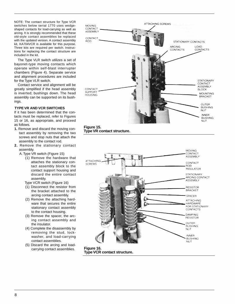
Figure 15.Type VR contact structure.
Figure 16.Type VCR contact structure.
NOTE: The contact structure for Type VCRswitches below serial 1770 uses wedge-shaped contacts for load-carrying as well asarcing. It is strongly recommended that theseold-style contact assemblies be replacedwith the updated version. A contact assemblykit, KA704VCR is available for this purpose.Three kits are required per switch. Instruc-tions for replacing the contact structure areincluded in the kit.
The Type VLR switch utilizes a set ofbayonet-type moving contacts whichoperate within self-blast interrupterchambers (Figure 4). Separate serviceand alignment procedures are includedfor the Type VLR switch.
Contact service and alignment will begreatly simplified if the head assemblyis inverted; bushings down. The headassembly can be supported on its bush-ings.
TYPE VR AND VCR SWITCHESIf it has been determined that the con-tacts must be replaced, refer to Figures15 or 16, as appropriate, and proceedas follows.1. Remove and discard the moving con-
tact assembly by removing the twoscrews and stop nuts that attach theassembly to the contact rod.
2. Remove the stationary contactassembly.A. Type VR switch (Figure 15)
(1) Remove the hardware thatattaches the stationary con-tact assembly block to thecontact support housing anddiscard the entire contactassembly.
Type VCR switch (Figure 16)(1) Disconnect the resistor from
the bracket attached to thearcing contact assembly.
(2) Remove the attaching hard-ware that secures the entirestationary contact assemblyto the contact housing.
(3) Remove the spacer, the arc-ing contact assembly andthe insulator.
(4) Complete the disassembly byremoving the stud, lock-washer, and load-carryingcontact assemblies.
(5) Discard the arcing and load-carrying contact assemblies.
S260-20-9
9
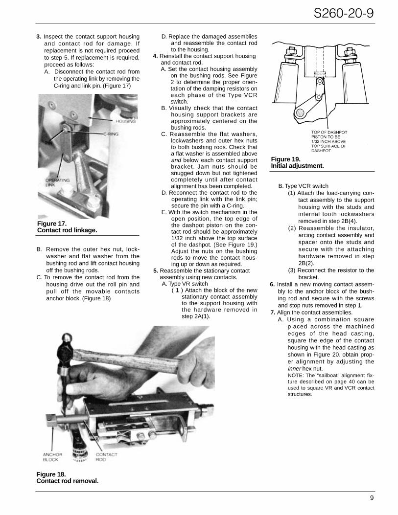
Figure 19.Initial adjustment.
Figure 18.Contact rod removal.
Figure 17.Contact rod linkage.
3. Inspect the contact support housingand contact rod for damage. Ifreplacement is not required proceedto step 5. If replacement is required,proceed as follows:A. Disconnect the contact rod from
the operating link by removing theC-ring and link pin. (Figure 17)
B. Remove the outer hex nut, lock-washer and flat washer from thebushing rod and lift contact housingoff the bushing rods.
C. To remove the contact rod from thehousing drive out the roll pin andpull off the movable contactsanchor block. (Figure 18)
D. Replace the damaged assembliesand reassemble the contact rodto the housing.
4. Reinstall the contact support housingand contact rod.A. Set the contact housing assembly
on the bushing rods. See Figure2 to determine the proper orien-tation of the damping resistors oneach phase of the Type VCRswitch.
B. VisualIy check that the contacthousing support brackets areapproximately centered on thebushing rods.
C. Reassemble the flat washers,lockwashers and outer hex nutsto both bushing rods. Check thata flat washer is assembled aboveand below each contact supportbracket. Jam nuts should besnugged down but not tightenedcompletely until after contactalignment has been completed.
D. Reconnect the contact rod to theoperating link with the link pin;secure the pin with a C-ring.
E. With the switch mechanism in theopen position, the top edge ofthe dashpot piston on the con-tact rod should be approximately1/32 inch above the top surfaceof the dashpot. (See Figure 19.)Adjust the nuts on the bushingrods to move the contact hous-ing up or down as required.
5. Reassemble the stationary contactassembly using new contacts.A. Type VR switch
( 1 ) Attach the block of the newstationary contact assemblyto the support housing withthe hardware removed instep 2A(1).
B. Type VCR switch(1) Attach the load-carrying con-
tact assembly to the supporthousing with the studs andinternal tooth lockwashersremoved in step 2B(4).
(2) Reassemble the insulator,arcing contact assembly andspacer onto the studs andsecure with the attachinghardware removed in step2B(2).
(3) Reconnect the resistor to thebracket.
6. Install a new moving contact assem-bly to the anchor block of the bush-ing rod and secure with the screwsand stop nuts removed in step 1.
7. Align the contact assemblies.A. Using a combination square
placed across the machinededges of the head casting,square the edge of the contacthousing with the head casting asshown in Figure 20. obtain prop-er alignment by adjusting theinner hex nut.NOTE: The “sailboat” alignment fix-ture described on page 40 can beused to square VR and VCR contactstructures.
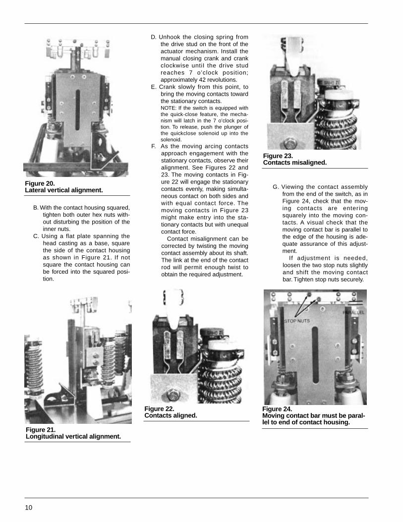
Figure 20.Lateral vertical alignment.
Figure 21.Longitudinal vertical alignment.
Figure 22.Contacts aligned.
Figure 23.Contacts misaligned.
Figure 24.Moving contact bar must be paral-lel to end of contact housing.
10
B. With the contact housing squared,tighten both outer hex nuts with-out disturbing the position of theinner nuts.
C. Using a flat plate spanning thehead casting as a base, squarethe side of the contact housingas shown in Figure 21. If notsquare the contact housing canbe forced into the squared posi-tion.
G. Viewing the contact assemblyfrom the end of the switch, as inFigure 24, check that the mov-ing contacts are enter ingsquarely into the moving con-tacts. A visual check that themoving contact bar is parallel tothe edge of the housing is ade-quate assurance of this adjust-ment.
If adjustment is needed,loosen the two stop nuts slightlyand shift the moving contactbar. Tighten stop nuts securely.
D. Unhook the closing spring fromthe drive stud on the front of theactuator mechanism. Install themanual closing crank and crankclockwise untiI the drive studreaches 7 o’clock position;approximately 42 revolutions.
E. Crank slowly from this point, tobring the moving contacts towardthe stationary contacts.NOTE: If the switch is equipped withthe quick-close feature, the mecha-nism will latch in the 7 o’clock posi-tion. To release, push the plunger ofthe quickclose solenoid up into thesolenoid.
F. As the moving arcing contactsapproach engagement with thestationary contacts, observe theiralignment. See Figures 22 and23. The moving contacts in Fig-ure 22 will engage the stationarycontacts evenly, making simulta-neous contact on both sides andwith equal contact force. Themoving contacts in Figure 23might make entry into the sta-tionary contacts but with unequalcontact force.
Contact misalignment can becorrected by twisting the movingcontact assembly about its shaft.The link at the end of the contactrod will permit enough twist toobtain the required adjustment.
S260-20-9
11
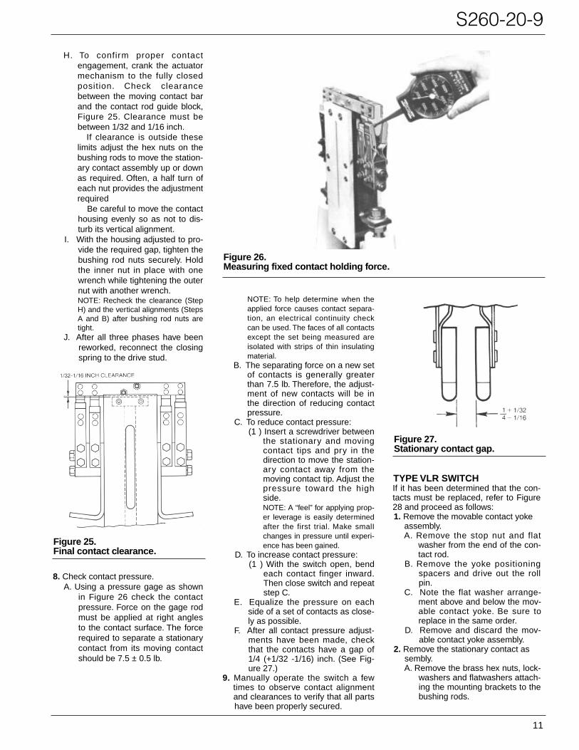
Figure 26.Measuring fixed contact holding force.
Figure 25.Final contact clearance.
H. To confirm proper contactengagement, crank the actuatormechanism to the fully closedposition. Check clearancebetween the moving contact barand the contact rod guide block,Figure 25. Clearance must bebetween 1/32 and 1/16 inch.
If clearance is outside theselimits adjust the hex nuts on thebushing rods to move the station-ary contact assembly up or downas required. Often, a half turn ofeach nut provides the adjustmentrequired
Be careful to move the contacthousing evenly so as not to dis-turb its vertical alignment.
I. With the housing adjusted to pro-vide the required gap, tighten thebushing rod nuts securely. Holdthe inner nut in place with onewrench while tightening the outernut with another wrench.NOTE: Recheck the clearance (StepH) and the vertical alignments (StepsA and B) after bushing rod nuts aretight.
J. After all three phases have beenreworked, reconnect the closingspring to the drive stud.
Figure 27.Stationary contact gap.
8. Check contact pressure.A. Using a pressure gage as shown
in Figure 26 check the contactpressure. Force on the gage rodmust be applied at right anglesto the contact surface. The forcerequired to separate a stationarycontact from its moving contactshould be 7.5 ± 0.5 lb.
NOTE: To help determine when theapplied force causes contact separa-tion, an electrical continuity checkcan be used. The faces of all contactsexcept the set being measured areisolated with strips of thin insulatingmaterial.
B. The separating force on a new setof contacts is generally greaterthan 7.5 lb. Therefore, the adjust-ment of new contacts will be inthe direction of reducing contactpressure.
C. To reduce contact pressure:(1 ) Insert a screwdriver between
the stationary and movingcontact tips and pry in thedirection to move the station-ary contact away from themoving contact tip. Adjust thepressure toward the highside.NOTE: A “feel” for applying prop-er leverage is easily determinedafter the first trial. Make smalIchanges in pressure until experi-ence has been gained.
D. To increase contact pressure:(1 ) With the switch open, bend
each contact finger inward.Then close switch and repeatstep C.
E. Equalize the pressure on eachside of a set of contacts as close-ly as possible.
F. After all contact pressure adjust-ments have been made, checkthat the contacts have a gap of1/4 (+1/32 -1/16) inch. (See Fig-ure 27.)
9. Manually operate the switch a fewtimes to observe contact alignment and clearances to verify that all parts have been properly secured.
TYPE VLR SWITCHIf it has been determined that the con-tacts must be replaced, refer to Figure28 and proceed as follows:1. Remove the movable contact yoke
assembly.A. Remove the stop nut and flat
washer from the end of the con-tact rod.
B. Remove the yoke positioningspacers and drive out the rollpin.
C. Note the flat washer arrange-ment above and below the mov-able contact yoke. Be sure toreplace in the same order.
D. Remove and discard the mov-able contact yoke assembly.
2. Remove the stationary contact assembly.A. Remove the brass hex nuts, lock-
washers and flatwashers attach-ing the mounting brackets to thebushing rods.

Figure 28.Type VLR switch contact assembly.
Figure 29.Dismantling contact tubes.
12
B. Lift the entire contact housingassembly from the bushings andthe contact rod, which remainsattached to the operating link.
3. Disassemble the stationary contactassembly.A. Remove the contact tube straps
by removing the round headmachine screw and associatedhardware.
B. To free the contact tubes from thehousing, grasp a tube firmly ineach hand and with a slowsteady movement spread thetubes away from the housing, asshown in Figure 29, until theband is released from the tubes.
C. Remove and discard the station-ary contact tube assemblies.
4. Reassemble the stationary contactstructure with new contact tubeassemblies.A. Use the reverse order of step 3B
and Figure 29 to reassemble thetubes and tube band, makingsure the notch in the tube linesup with the tab in the band.
B. Secure the tubes to the housingwith the tube straps.
5. Reinstall the stationary contact struc-ture into the switch.A. Install the assembly over the con-
tact rod and attach to the bush-ing rods with the flat washers,lockwashers, and brass nuts; donot tighten.
Figure 30.Checking axial and longitudinalsquareness with “sailboat” align-ment fixture.
6. Align the stationary contact assembly.A. With the switch mechanism in theopen position, the top of the dashpotpiston on the contact rod should be1/32 inch above the top surface ofthe dashpot. (See Figure 19.) Adjustthe nuts on the bushing rod to movethe contact housing up or down asrequired.B. With a “sailboat” alignment fixture
spanning the machined surfacesof the head casting, check theaxial squareness of the contacthousing as shown in Figure 30.obtain proper squareness byadjusting the bushing nuts while
maintaining the alignment of step6A.NOTE: A typical sailboat alignmentfixture is shown in Figure 31. If a fix-ture is not available the procedure foraligning VR and VCR contact boxes,described on page 31, can be used.
C. With the contact housing squared,tighten both outer bushing nutssecurely without disturbing theposition of the inner nuts.
D. Square the side of the contacthousing with the head casting asshown in Figure 30. If misalign-ment exists, adjust by bendingthe entire structure as required.
7. Install and align the movable contactyoke assembly.A. Replace the correct number of
washers above and below thecontact yoke as noted in Step 1C during disassembly.
B. Reinstall roll pin, spacers, washerand stop nut to complete thereassembly.
C. Unhook the closing spring fromthe drive stud and manuallycrank the mechanism until thedrive stud reaches the 7 o’clockposition; approximately 42 revo-lutions.
D. Crank slowly from this point tobring moving contacts toward thestationary contacts.NOTE: If switch is equipped withquickclose accessory, the mecha-nism will latch in the 7 o-clock posi-tion. To release, push the quick closesolenoid plunger up into the solenoid.
E. As the moving contacts approachthe stationary contacts observetheir alignment. Misalignmentcan be corrected by twisting the
S260-20-9
13
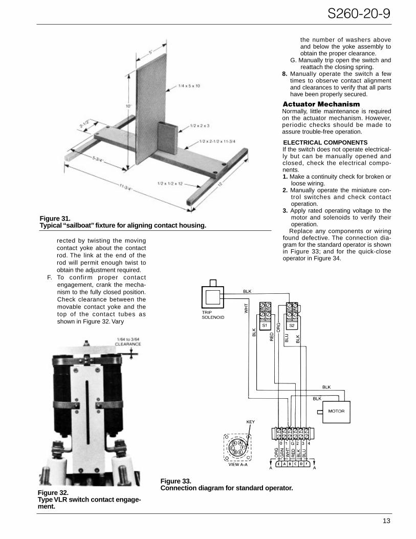
Figure 31.Typical “sailboat” fixture for aligning contact housing.
Figure 32.Type VLR switch contact engage-ment.
Figure 33.Connection diagram for standard operator.
rected by twisting the movingcontact yoke about the contactrod. The link at the end of therod will permit enough twist toobtain the adjustment required.
F. To confirm proper contactengagement, crank the mecha-nism to the fully closed position.Check clearance between themovable contact yoke and thetop of the contact tubes asshown in Figure 32. Vary
the number of washers aboveand below the yoke assembly toobtain the proper clearance.
G. Manually trip open the switch andreattach the closing spring.
8. ManualIy operate the switch a fewtimes to observe contact alignmentand clearances to verify that all partshave been properly secured.
Actuator MechanismNormally, little maintenance is requiredon the actuator mechanism. However,periodic checks should be made toassure trouble-free operation.
ELECTRICAL COMPONENTSIf the switch does not operate electrical-ly but can be manually opened andclosed, check the electrical compo-nents.1. Make a continuity check for broken or
loose wiring.2. Manually operate the miniature con-
trol switches and check contactoperation.
3. Apply rated operating voltage to themotor and solenoids to verify theiroperation.
Replace any components or wiringfound defective. The connection dia-gram for the standard operator is shownin Figure 33; and for the quick-closeoperator in Figure 34.
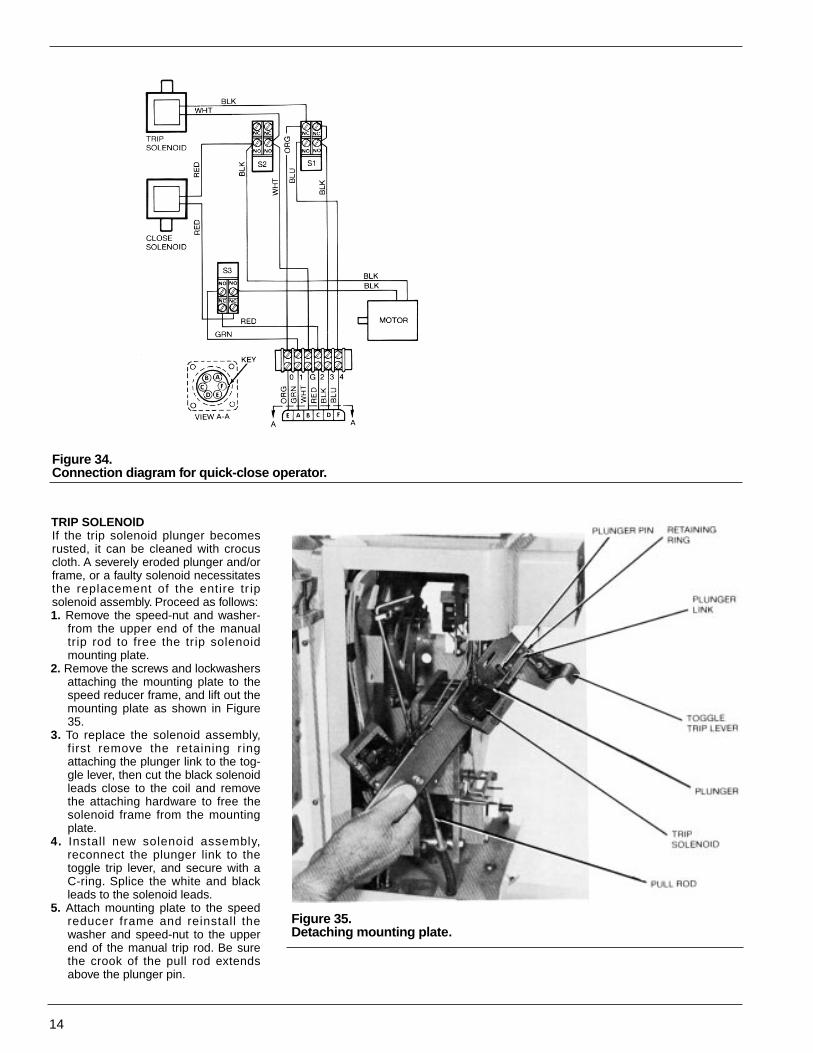
Figure 34.Connection diagram for quick-close operator.
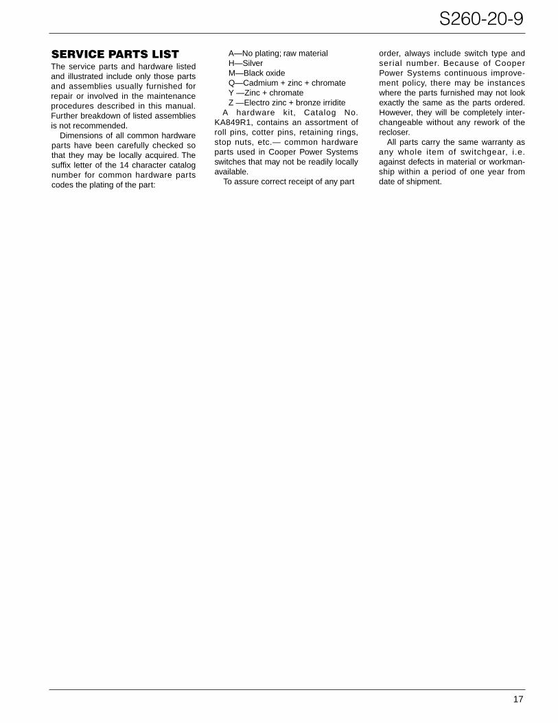
Figure 35.Detaching mounting plate.
14
TRIP SOLENOlDIf the trip solenoid plunger becomesrusted, it can be cleaned with crocuscloth. A severely eroded plunger and/orframe, or a faulty solenoid necessitatesthe replacement of the entire tr ipsolenoid assembly. Proceed as follows:1. Remove the speed-nut and washer-
from the upper end of the manualtrip rod to free the trip solenoidmounting plate.
2. Remove the screws and lockwashersattaching the mounting plate to thespeed reducer frame, and lift out themounting plate as shown in Figure35.
3. To replace the solenoid assembly,first remove the retaining r ingattaching the plunger link to the tog-gle lever, then cut the black solenoidleads close to the coil and removethe attaching hardware to free thesolenoid frame from the mountingplate.
4. Install new solenoid assembly,reconnect the plunger link to thetoggle trip lever, and secure with aC-ring. Splice the white and blackleads to the solenoid leads.
5. Attach mounting plate to the speedreducer frame and reinstall thewasher and speed-nut to the upperend of the manual trip rod. Be surethe crook of the pull rod extendsabove the plunger pin.

S260-20-9
15
Figure 36.Actuator parts identification.
Figure 37.Operating shaft lever attachement.
MOTOR REPLACEMENTThe actuator motor used in Type VR,VCR, and VLR switches with serialnumbers below those listed in Table 4 isno longer available. To adapt the newmotor to these switches a motorreplacement kit, KA725VR, is available.The kit includes the new motor and allpar ts required for the adaptation.Replacement instructions are includedwith the kit.
Switches with serial numbers abovethose referenced in Table 4 have thenew design motors installed duringmanufacture and do not require thereplacement kit. They may be replaceddirectly on a one-to-one basis.
To replace a motor simply disconnectthe motor leads and remove the attach-ing hardware. Make sure the drive gearon the motor shaft meshes correctlywith its mating reduction gear wheninstalling the new motor.
BelowType Serial Number
VR 2809 VCR 2344VLR 1208
SPEED REDUCERSpeed reducer maintenance is limitedto a periodic greasing of gears with anallweather, non-freezing grease. Ifspeed reducer must be replaced, referto Figure 36 and proceed as follows:
1. With the main switch contacts open,remove the closing spring from thecrank lever drive pin.
2. Disconnect the two black motorleads.
3. Remove the pull rod and the mount-ing plates. See page 45.
4. Remove the C ring, identified in Fig-ure 37, to free the toggle assemblypin. Raisethetripleverandpullout-thepin, releasing a spacer andfreeing the spring link and togglefrom the shaft lever.
Table 4Switches Requiring MotorReplacemnt Kit.

Figure 38.Detached speed reducer.
16
5. Remove hexhead screws that securethe speed reducer to the actuatorhousing.
6. Lift out the speed reducer with toggleassembly and opening spr ingsattached as shown in Figure 38.Remove the springs from the lowerspring link.
7. Remove the C ring to release the flatwasher, lower spring link, spacer andtoggle assembly from the toggleshaft. Remove C ring and closingspring bushing from the crank lever.
8. Replace spring link and spacer ontoggle shaft of new speed reduc-erand secure with C ring. Attachopening springs to spring link.
CAUTION: Stop bolt, foroperating shaft lever, is factory
set and should never be readjusted.
!
9. Install new speed reducer in actua-tor housing. Moderately tighten hex-head screws. Be sure latch lever ispositioned behind stop-lever roll pinas shown in Figure 36.
10. Lift trip lever and insert toggle pin tosecure toggle, spacer, and upperspring link to shaft lever. Secure pinwith C ring. Attach opening springsto upper spring link. Be sure toggle,spacer, and link are positioned as inFigure 37.
11. Attach mounting plate to speedreducer frame. Slip pull rod throughmounting plate slot and secure withspeed nut and washer.
12. Tighten hexhead screws that securespeed reducer to actuator housing.
13. Install closing spring bushing andsecure with C ring.
14. Attach closing spring onto cranklever drive pin. Operate actuatormechanism manually with crank toclose contacts. Open contacts withmanual trip rod. Repeat operationof actuator mechanism electricallyand check for proper operation.
S260-20-9
17
SERVICE PARTS LISTThe service parts and hardware listedand illustrated include only those partsand assemblies usually furnished forrepair or involved in the maintenanceprocedures described in this manual.Further breakdown of listed assembliesis not recommended.
Dimensions of all common hardwareparts have been carefully checked sothat they may be locally acquired. Thesuffix letter of the 14 character catalognumber for common hardware partscodes the plating of the part:
A—No plating; raw materialH—SilverM—Black oxideQ—Cadmium + zinc + chromateY —Zinc + chromateZ —Electro zinc + bronze irridite
A hardware kit, Catalog No.KA849R1, contains an assortment ofroll pins, cotter pins, retaining rings,stop nuts, etc.— common hardwareparts used in Cooper Power Systemsswitches that may not be readily locallyavailable.
To assure correct receipt of any part
order, always include switch type andserial number. Because of CooperPower Systems continuous improve-ment policy, there may be instanceswhere the parts furnished may not lookexactly the same as the parts ordered.However, they will be completely inter-changeable without any rework of therecloser.
All parts carry the same warranty asany whole item of switchgear, i.e.against defects in material or workman-ship within a period of one year fromdate of shipment.

Figure 39.Tank and head assembly parts.
18

S260-20-9
19
Tank and Head Assembly Parts (Figure 39)
Qty.Item Catalog PerNo. Description Number Assy.
1 Bushing assembly, complete(includes items 6, 7, 8 and 9)Standard creepage KA160E7 617-inch creepage KA160E8 6
2 Capscrew, hex hd, 3/8-16 x1-5/8, stl K730101137162Q 18
3 Bushing clamp KP41L 184 Clamping ring KP121L 65 Lower bushing gasket KP2020A29 66 Terminal KA143L900 17 Terminal gasket KP2090A57 18 Ceramic bushing
Standard creepage KP130VR 117-inch extra creepage KP318VR 1
9 Bushing rod KA160E907 110 Vented dipstick KA213VR 111 O-ring gasket KP2000A46 112 Capscrew, hex hd, 3/8-16
x 3, stl K73101137300Q 1013 Washer KP2028A23 1014 Combination nut and pin KP3061A3 1015 Capscrew, hex hd,1/2-13
x 1-1/4, stl K730101150125Q 216 Split lockwasher, med,1/2, stl K900801050000Z 217 Lifting lug KP456H1 2
Qty.Item Catalog PerNo. Description Number Assy.
18 Head casting (includesoperating shaft bushing) KA701VR 1
19 Oil seal KP259VR 120 Head gasket KP2103A6 121 Shaft and levers assembly KA23VR 122 Rubber seal KP2090A44 123 Indicator KA19VR 124 Roll pin, 3/16 x 1-1/8, stl K970801187112M 125 Washer KP164VR 126 External retaining ring KP2013A1 127 Shaft bearing KP88VR 128 Split lockwasher, med, 5/8, stl K900801062000Q 629 Capscrew, hex hd, 5/8-18 x 2,
stl K730101162200Q 630 Retaining ring, Type C, 1/4
stl (WA514) K970901250000M 631 Pin KP3124A18 332 Contact operating link KP17VR 333 Tank liner kit KA761H3-2 134 Tank assembly KA3VCR 135 Capscrew, hex hd, 1/2-13 x 1,
stl K730101150100Q 136 Parallel ground clamp KA227H 137 Pipe plug 1/2, sq hd KP2007A3 138 Oil sampling and drain valves KA809R 1

Figure 40.Type VR contact assembly parts.
20
Type VR Contact Assembly Parts (Figure 40)Qty.
Item Catalog PerNo. Description Number Assy.
1 Hex jam nut, light, 5/8-18,brass K880725318062A 4
2 Washer KP2028A45 43 Split lockwasher, med, 5/8,
bronze K900830062000A 24 Retaining ring, Type C, 1/4,
stl (WA514) K970901250000M 25 Pin KP31 24A18 16 Contact rod assembly KA200VR 1
Stationary contact assemblycomplete (includes items 7through 11) KA199VR1 1
Qty.Item Catalog PerNo. Description Number Assy.
7 Contact housing supportassembly KA211 VR1 1
8 Mounting bracket KP134VR1 29 Stationary contact assembly KA209VR 210 Capscrew, hex hd, 5/16-18 x
2-1/4, stl K730101131225A 411 Split lockwasher, med, 5/8, stl K900801062000A 412 Movable contact assembly KA201VR 113 Machine screw, rd hd, 10-32
x 1, stl K721501310100A 2

S260-20-9
21
Type VCR Contact Assembly (Figure 41)
Figure 41.Type VCR contact assembly parts.
Qty.Item Catalog PerNo. Description Number Assy.
14 Double-ended stud KP138VCR 415 Plate, right hand KP127VCR1 1
Plate, left hand KP127VCR2 116 Stationary contact assembly,
arcingRight hand KA33VCR1 1Left hand KA33VCR2 1
17 Plate KP128VCR 218 Plain washer, 5/16, SAE, stl K900201031000A 419 Internal tooth lockwasher,
5/16, sil brz K901033031000A 420 Hex nut, 5/16-18, stl K881001118031A 421 Resistor mounting bracket
right hand KP118VCR901 1Resistor mounting bracket,left hand KP118VCR902 1
22 Split lockwasher, med, No. 8,stl K900801008000A 4
23 Machine screw rd hd8-32 x 7/16, stl K721501108043A 4
24 Resistor, 3.2 ohms (CutlerHammer G3AL320) K999904250136A 2
Qty.Item Catalog PerNo. Description Number Assy.
1 Hex jam nut, light, 5/8-18brass K88072S318062A 4
2 Washer KP2028A45 43 Split lockwasher K9008300620000A 24 Retaining ring, Type C, 1/4,
stl (WA514) K970901250000M 25 Pin KP3124A18 1
Contact assembly, complete(includes items 6 through 24) KA704VCR 1
6 Contact rod assembly KA200VR 17 Movable contact assembly KA36VCR 18 Machine screw, rd hd, 10-32
x 1, stl K721501310100A 29 Elastic stop nut, 10-32 KP2020A1 2
Stationary contact assemblycomplete (includes items 10through 24) KA30VCR 1
10 Contact support assembly KA34VCR 111 Mounting bracket KP134VR2 212 Stationary contact assembly,
load KA32VRC 213 Internal tooth lockwasher
5/16 sil brz K901033031000A 4
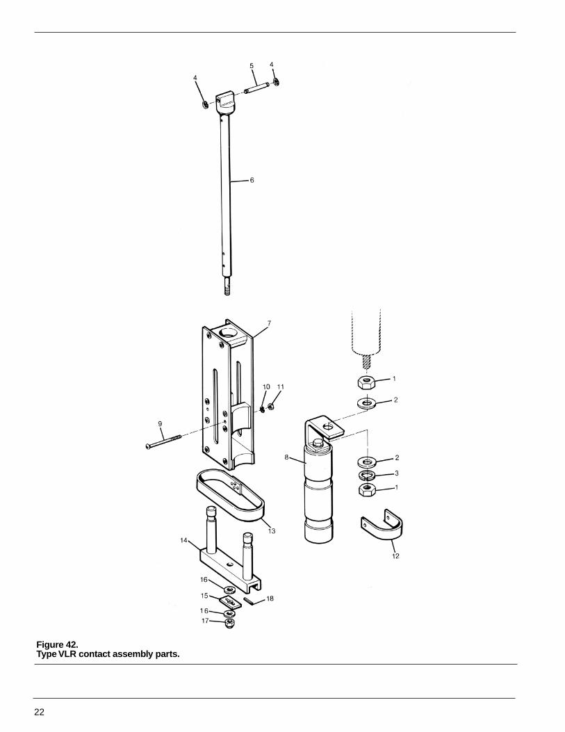
Figure 42.Type VLR contact assembly parts.
22

S260-20-9
23
Type VLR Contact Assembly (Figure 42)
Qty.Item Catalog PerNo. Description Number Assy.
9 Machine screw, rd hd, 10-32x 2-1/2, stl K721501310250A 2
10 Split lockwasher, medNo. 10, stl K900801010000Z 2
11 Hex nut, 10-32, stl K881001332010A 212 Tube strap KP111 VLR 213 Contact tube band KA98VR 114 Movable contact yoke
assembly KA16VLR 115 Spacer KP1505R 116 Plain washer, 5/8 SAE,
steel K900201031000A 417 Stop nut KP2020A4 118 Roll pin, 1/8 x 13/16 K970801125081M 1
QtyItem Catalog PerNo. Description Number Assy.
1 Hex jam nut, light, 5/8-18,brass K880725318062A 4
2 Washer KP2028A4S 43 Split lockwasher, med, 5/8
bronze K900830062000A 24 Retaining ring, Type C 1/4
stl (WAS14) K970901250000M 25 Pin KP3124A18 16 Contact rod assembly KA5VLR 1
Stationary contact assemblycomplete (includes items 7through 13) KA4VLR1 1
7 Contact housing support KA3VLR 18 Stationary contact housing
assembly KA7VLR 1 2
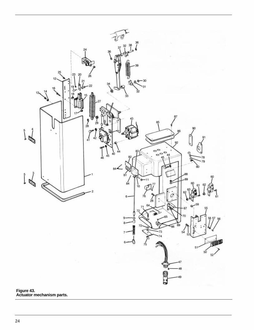
Figure 43.Actuator mechanism parts.
24

S260-20-9
25
Actuator Mechanism Parts (Figure 43)
Qty.Item Catalog PerNo. Descrliption Number Assy.
49 Plug assembly KA98NR 150 Terminal strip KP2101A7 151 Marker KP40VR 152 Machine screw, rd hd, 8-32
x 3/4, stl K721501108075Z 253 Split lockwasher, med, No. 8,
stl K900801008000Z 254 Hex nut, 8-32, stl K881001132008Z 255 Switch mounting panel KP344VR 156 Machine screw, rd hd, 100-32
x 3/4, stl K721501310075Z 357 Split lockwasher, med, No. 10,
stl K900801010000Z 358 Plain washer, No. 10, stl K900201010000Z 359 Spacer KP3007A37 360 Switch and latch assembly KA182VR900 261 Machine screw, rd hd, 8-32
x 1/2, stl K721501108050Z 462 Elastic stop nut, 8-32 KP2020A5 463 Spacer KP3007A35 264 Crank assembly KP141VR 165 Self-tap screw, pan hd,.10-32
x 1/8, sst KP751717110037A 166 Mounting clip KP1091ME 167 Latch-in spring KP72VR 168 Machine screw, rd hd, 10-32
x 7/8, stl K721501310087Z 269 Split lockwasher, med, No. 10
stl K900201010000Z 270 Hex nut, 10-32, stl K881001332010Z 271 Machine screw, rd hd, 5/16-18
x 1-1/4, brass K721525131125A 172 Flat washer, 5/16 AN, stl K900201032056Z 273 Hex nut, 5/16-28, stl K880201118031Q 174 Latch KP268VR 175 Wing nut K881201118031Z 176 Counter assembly KA28C03 177 Self-tap screw, rd hd, No. 6
x 3/8, sst K801515006037A 278 Capscrew, hex hd, 3/8-16
x 1-1/2, stl K730101137150Q 179 Hex nut, 3/8-16, stl K880201116037Q 180 Split lockwaser, med, 3/8, stl K900801037000Z 181 Plate, CLOSED KP729R 182 Nameplate KP131 VR 183 Control rating plate KP289VR1 684 Self-tap screw, rd hd, Type Z,
No. 2 x 3/16, stl K801515002018A 685 Cover KP158VR 186 Gasket KP649VR 187 Machine screw, rd hd, 10-32
x 3/4, sst K721515310075A 488 Split lockwasher, med, No. 10,
stl K900801010000Z 489 Hex nut, 10-32, stl K880201332010Z 490 Gasket KP78VR 191 Gasket KP77VR 192 Mechanism housing KA230VR1 193 Capscrew, hex hd, 3/8-16 x 1,
stl K730101137100Q 494 Split lockwasher, med, 3/8, stl K900801037000Z 4
Qty.Item Catalog PerNo. Description Number Assy.
1 Cover KP129VR 12 Cover gasket KP2084A1 13 Plate, MANUAL TRIP KP245VR 14 Plate, OPEN KP730R 15 Self-tap screw, rd hd, Type Z,
No. 2 x 3/16, sst K801515002018A 46 Manual trip assembly KA65VR900 17 Spring KP157VR 18 Spacer KP3007A8 19 Plain washer, 1/4 AN, stl K900201026050Z 110 Plain washer, No. 10S, brass K900525020043A 111 Speed nut KP2005A1 112 Mounting plate KP87VR 113 Machine screw, rd hd, 10-32
x 3/4, sst K721515310075A 214 Split lockwasher, med, No. 10,
stl K900801010000Z 215 Trip solenoid assembly
120 vac KA185VR1 1125 vdc KA185VR2 148 vdc KA185VR3 124 vdc KA185VR4 1
16 Machine screw, 10-32 x 1/2, stl K72150130050Z 417 Elastic stop nut, 10-32 KP2020A1 418 Nylon wire clip KP2006A1 119 Pin KP314VR 120 Link KP83VR 121 Spacer KP3004A24 122 Plain washer, No. 6 SAE, stl K900201006000Z 123 Retaining ring, Type C, 1/4,
stl (WA514) K970901250000M 124 Support and lever assembly KA41VR 125 Machine screw, 10-32 x 1/2, stl K721501310050Z 226 Elastic stop nut, 10-32 KP2020A1 227 Closing spring KP533GW 128 Retaining ring, Type C, 3/8,
stl (WA518) K970901375000M 129 Sleeve KP280VR 130 Retaining ring, Type C, 5/16,
stl (WA516) K970901312000M 131 Plain washer, No. 20S, brass K900525312000A 132 Spring link KP31VR 233 Spacer KP3011A6 134 Plain washer, 1/2, brass K900525056125A 135 Toggle assembly KA11 VR1 136 Retaining ring Type C, 5/16,
stl K970901312000A 237 Spacer KP3010A7 138 Pin KP3125A7 139 Opening spring KP35VR 240 Speed reducer (includes items
42 through 45) KA32VR 141 Capscrew, hex hd, 5/16-18
x 3/4, stl K731001131075Q 442 Split lockwasher, med, 5/16, stl K900801031000Z 443 Motor assembly KA225VR 144 Spacer KP3009A159 345 Split lockwasher, med, 14, stl K900801025000Z 346 Machine screw, rd hd, 1/4-28
x 1 -18, stl K721501325112Q 347 Receptacle assembly KA129VR 148 Self tap screw, rd hd, Type Z,
No. 6 x 3/8, stl K801515006037A 4
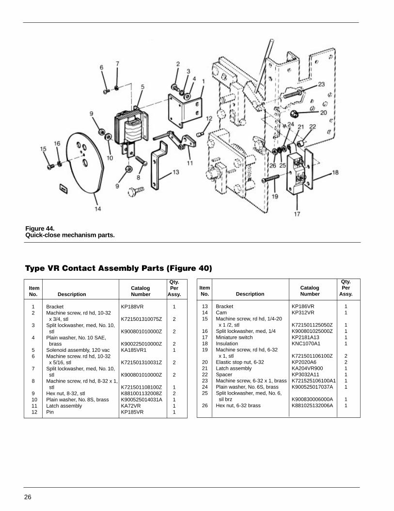
Figure 44.Quick-close mechanism parts.
26
Type VR Contact Assembly Parts (Figure 40)
Qty.Item Catalog PerNo. Description Number Assy.
1 Bracket KP188VR 12 Machine screw, rd hd, 10-32
x 3/4, stl K721501310075Z 23 Split lockwasher, med, No. 10,
stl K900801010000Z 24 Plain washer, No. 10 SAE,
brass K900225010000Z 25 Solenoid assembly, 120 vac KA185VR1 16 Machine screw. rd hd, 10-32
x 5/16, stl K721501310031Z 27 Split lockwasher, med, No. 10,
stl K900801010000Z 28 Machine screw, rd hd, 8-32 x 1,
stl K721501108100Z 19 Hex nut, 8-32, stl K881001132008Z 210 Plain washer, No. 8S, brass K900525014031A 111 Latch assembly KA72VR 112 Pin KP185VR 1
Qty.Item Catalog PerNo. Description Number Assy.
13 Bracket KP186VR 114 Cam KP312VR 115 Machine screw, rd hd, 1/4-20
x 1 /2, stl K721501125050Z 116 Split lockwasher, med, 1/4 K900801025000Z 117 Miniature switch KP2181A13 118 Insulation KNC1070A1 119 Machine screw, rd hd, 6-32
x 1, stl K721501106100Z 220 Elastic stop nut, 6-32 KP2020A6 221 Latch assembly KA204VR900 122 Spacer KP3032A11 123 Machine screw, 6-32 x 1, brass K721525106100A1 124 Plain washer, No. 6S, brass K900525017037A 125 Split lockwasher, med, No. 6,
sil brz K900830006000A 126 Hex nut, 6-32 brass K881025132006A 1


KBP11/83
P.O. Box 2850, Pittsburgh, PA 15230©1989 Cooper Industries, Inc.