S SERIES SUBMERSIBLE PUMPSSUBMERSIBLE PUMPS. S SERIES PUMPS OM-04151 ... The integral electric motor...
34
PUBLICATION NUMBER OM-04151 December 12, 1994 Rev. G 08‐09‐18 GORMAN‐RUPP PUMPS www.grpumps.com e1994 Gorman‐Rupp Pumps Printed in U.S.A. S SERIES SUBMERSIBLE PUMPS
Transcript of S SERIES SUBMERSIBLE PUMPSSUBMERSIBLE PUMPS. S SERIES PUMPS OM-04151 ... The integral electric motor...
PUBLICATION NUMBER OM-04151December 12, 1994Rev. G 08‐09‐18
GORMAN‐RUPP PUMPSwww.grpumps.com
�1994 Gorman‐Rupp Pumps Printed in U.S.A.
S SERIESSUBMERSIBLE PUMPS
OM-04151S SERIES PUMPS
PAGE I - 1INTRODUCTION
INTRODUCTION
Thank You for purchasing a Gorman‐Rupp S Se
ries Pump. Read this manual carefully to learn
how to safely install and operate your pump. Fail
ure to do so could result in personal injury or dam
age to the pump.
A set of three manuals accompanies your pump.
Each set consists of three parts; the Installation/
Operation Manual contains essential information
on installing and operating the pump, and on mak
ing electrical connections. However, since pump
installations are seldom identical, some of the in
formation only summarizes general recommenda
tions and practices required to inspect, position,
and arrange the pump and piping.
The Parts List Manual provides performance
curve(s), a pump model cross‐section drawing,
and parts list for your pump.
The Maintenance and Repair Manual provides
troubleshooting and maintenance instructions re
quired to properly diagnose operational problems,
and to service the pump hydraulic components.
Pump motor maintenance may be performed only
by a Gorman‐Rupp authorized repair facility, or the
factory. Otherwise, the pump warranty will be ne
gated, and damage to the pump, and injury or
death to personnel can result. Contact the factory
for the authorized repair facility closest to you.
The integral electric motor must be operated
through the control box furnished with the pump as
standard equipment. If the motor is dual‐voltage,
the pump is shipped from the factory wired only for
the voltage shown on the nameplate. If desired to
have the voltage changed, return the pump to the
factory or to a Gorman‐Rupp authorized submers
ible repair facility.
The pump motor must be operated through an ap
propriate control box matching the voltage, phase
and other characteristics of the motor. The control
box must be approved by Gorman‐Rupp for the
application and environment intended, and must
also provide for proper operation of the motor pro
tection devices, such as the integral moisture and
thermal switches. Control boxes and other control
devices not integral to the pump are not covered
in this manual.
Pump construction may be aluminum with ductile
iron or steel wearing parts, or stainless steel fitted,
or completely stainless steel. The pump may be
operated fully or partially submerged. Neither the
pump nor the control box are explosion‐proof, and
should not be operated in a hazardous atmo
sphere.
Because pump installations are seldom identical,
this manual cannot possibly provide detailed in
structions and precautions for every aspect of
each specific application. Therefore, it is the re
sponsibility of the owner/installer of the pump to
ensure that applications not addressed in this
manual are performed only after establishing that
neither operator safety nor pump integrity are com
promised by the installation. Pumps and related
equipment must be installed and operated ac
cording to all national, local and industry stan
dards.
If there are any questions regarding the pump
which are not covered in this manual or in other lit
erature accompanying the unit, please contact
your Gorman‐Rupp distributor or the Gorman‐
Rupp Company:
The Gorman‐Rupp Company
P.O. Box 1217
Mansfield, Ohio 44901-1217
or:
Gorman‐Rupp of Canada Limited
70 Burwell Road
St. Thomas, Ontario N5P 3R7
CONTENTS
SAFETY - SECTION A
INSTALLATION - SECTION B
GENERAL INFORMATION PAGE B - 1. . . . . . . . . . . . . . . . . . . . . . . . . . . . . . . . . . . . . . . . . . . . . . . . . . . . .
PREINSTALLATION INSPECTION PAGE B - 1. . . . . . . . . . . . . . . . . . . . . . . . . . . . . . . . . . . . . . . . . . . . . . .
LUBRICATION PAGE B - 1. . . . . . . . . . . . . . . . . . . . . . . . . . . . . . . . . . . . . . . . . . . . . . . . . . . . . . . . . . . . . . . .
MOTOR SPECIFICATIONS PAGE B - 2. . . . . . . . . . . . . . . . . . . . . . . . . . . . . . . . . . . . . . . . . . . . . . . . . . . . .
PUMP INSTALLATION PAGE B - 10. . . . . . . . . . . . . . . . . . . . . . . . . . . . . . . . . . . . . . . . . . . . . . . . . . . . . . . .
OM-04151 S SERIES PUMPS
PAGE I - 2 INTRODUCTION
ELECTRICAL CONNECTIONS PAGE B - 11. . . . . . . . . . . . . . . . . . . . . . . . . . . . . . . . . . . . . . . . . . . . . . . . .
OPERATION - SECTION C
GENERAL INFORMATION PAGE C - 1. . . . . . . . . . . . . . . . . . . . . . . . . . . . . . . . . . . . . . . . . . . . . . . . . . . . .
PUMP OPERATION PAGE C - 1. . . . . . . . . . . . . . . . . . . . . . . . . . . . . . . . . . . . . . . . . . . . . . . . . . . . . . . . . . .
STARTING, STOPPING, AND OPERATIONAL CHECKS PAGE C - 3. . . . . . . . . . . . . . . . . . . . . . . . . . . .
COLD WEATHER PRESERVATION PAGE C - 4. . . . . . . . . . . . . . . . . . . . . . . . . . . . . . . . . . . . . . . . . . . . . .
LUBRICATION PAGE C - 4. . . . . . . . . . . . . . . . . . . . . . . . . . . . . . . . . . . . . . . . . . . . . . . . . . . . . . . . . . . . . . . .
RECORDING MODEL AND
SERIAL NUMBERS
Please record the pump model, serial number, volt
age, and motor frame size in the spaces provided
below. Your Gorman‐Rupp distributor needs this
information when you require parts or service.
Pump Model:
Serial Number:
Voltage:
Phase:
WARRANTY INFORMATION
The warranty provided with your pump is part of
Gorman‐Rupp's support program for customers
who operate and maintain their equipment as de
scribed in this and the other accompanying litera
ture. Please note that should the equipment be
abused or modified to change its performance be
yond the original factory specifications, the war
ranty will become void and any claim will be de
nied.
The following are used to alert personnel to procedures which require special attention, to those which
could damage equipment, and to those which could be dangerous to personnel:
Immediate hazards which WILL result insevere personal injury or death. Theseinstructions describe the procedure required and the injury which will resultfrom failure to follow the procedure.
Hazards or unsafe practices whichCOULD result in severe personal injuryor death. These instructions describethe procedure required and the injurywhich could result from failure to followthe procedure.
Hazards or unsafe practices which COULDresult in minor personal injury or product orproperty damage. These instructions describe the requirements and the possibledamage which could result from failure tofollow the procedure.
NOTEInstructions to aid in installation, operation, and
maintenance or which clarify a procedure.
OM-04151 S SERIES PUMPS
PAGE A - 1SAFETY
SAFETY - SECTION A
This information applies to the S Seriessubmersible motor driven pumps andcontrol boxes.
Because pump installations are seldomidentical, this manual cannot possiblyprovide detailed instructions and precautions for each specific application.Therefore, it is the owner/installer's responsibility to ensure that applicationsnot addressed in this manual are performed only after establishing that neither operator safety nor pump integrityare compromised by the installation.
Before attempting to open or service thepump:
1. Familiarize yourself with this manual.
2. Lock out incoming power to thecontrol box to ensure that thepump will remain inoperative.
3. Allow the pump to completely coolif overheated.
5. Close the discharge valve (ifused).
This pump is not designed to pump volatile, explosive, or flammable materials.Do not attempt to pump any liquids forwhich you pump is not approved, orwhich may damage the pump or endanger personnel as a result of pump failure. Consult the factory for specific application data.
Before connecting any cable to the control box, be sure to ground the controlbox. Refer to the Control Box Manual forthe suggested grounding methods.
The pump motor is designed to be operated through the control box furnishedwith the pump. The control box providesoverload protection and power control.Do not connect the pump motor directlyto the incoming power lines.
The electrical power used to operatethis pump is high enough to cause injury or death. Obtain the services of aqualified electrician to make all electrical connections. Make certain that thepump and enclosure are properlygrounded; never use gas pipe as anelectrical ground. Be sure that the incoming power matches the voltage andphase of the pump and control beforeconnecting the power source. Do notrun the pump if the voltage is not withinthe limits. If the overload unit is trippedduring pump operation, correct theproblem before restarting the pump.
The electrical power used to operatethis pump is high enough to cause injury or death. Make certain that the controlhandle on the control box is in the OFF
S SERIES PUMPS OM-04151
PAGE A-2 SAFETY
position and locked out, or that the power supply to the control box has beenotherwise cut off and locked out, beforeattempting to open or service the pumpassembly. Tag electrical circuits to prevent accidental start‐up.
Never attempt to alter the length or repair any power cable with a splice. Thepump motor and cable must be completely waterproof. Injury or death mayresult from alterations.
All electrical connections must be in accordance with The National ElectricCode and all local codes. If there is aconflict between the instructions provided and N.E.C. Specifications, N.E.C.Specifications shall take precedence.All electrical equipment supplied withthis pump was in conformance withN.E.C. requirements in effect on thedate of manufacture. Failure to followapplicable specifications, or substitution of electrical parts not supplied orapproved by the manufacturer, can result in severe injury or death and voidwarranty.
Death or serious personal injury anddamage to the pump or componentscan occur if proper lifting proceduresare not observed. Make certain thathoists, chains, slings or cables are ingood working condition and of sufficient capacity and that they are positioned so that loads will be balanced
and the pump or components will not bedamaged when lifting. Do not attempt tolift this pump by the motor or controlcables, or the piping. Attach proper lifting equipment to the lifting bail fitted onthe pump. Lift the pump or componentonly as high as necessary and keep personnel away from suspended objects.
After the pump has been installed, makecertain that the pump and all piping orhose connections are secure before operation.
Obtain the services of a qualified electrician to troubleshoot, test and/or service the electrical components of thispump.
Approach the pump cautiously after ithas been running. Although the motor iscooled by the liquid being pumped, normal operating temperatures can be highenough to cause burns. The temperature will be especially high if operatedagainst a closed discharge valve. Neveroperate against a closed dischargevalve for long periods of time.
Do not remove plates, covers, gauges,pipe plugs, or fittings from an overheated pump. Vapor pressure within thepump can cause parts being disengaged to be ejected with great force. Al
OM-04151 S SERIES PUMPS
PAGE A - 3SAFETY
low the pump to completely cool beforeservicing.
Do not attempt to lift the pump by themotor power cable or the piping. Attachproper lifting equipment to the liftingdevice fitted to the pump. If chains orcable are wrapped around the pump to
lift it, make certain that they are positioned so as not to damage the pump,and so that the load will be balanced.
Pumps and related equipment must beinstalled and operated according to all national, local and industry standards.
S SERIES PUMPS OM-04151
PAGE B - 1INSTALLATION
INSTALLATION - SECTION B
GENERAL INFORMATION
Review all SAFETY information in Section A.
Since pump installations are seldom identical, this
section is intended only to summarize general rec
ommendations and practices required to inspect,
position, and arrange the pump and piping. If there
are any questions concerning your specific instal
lation, contact your Gorman‐Rupp distributor or
the Gorman‐Rupp Company.
Liquid level devices are available from Gorman‐
Rupp as optional equipment. For information on
installing and operating these items, refer to the lit
erature accompanying them.
Pump Model Designation
Following is a description of the model numbering
system for S Series pumps. These submersible
pumps are available in a range of sizes. Refer to the
following chart to identify the size for your specific
pump model.
S
SeriesDischarge Size
Pump HydraulicsPump Construction
H.P. (If Shown)
Voltage/Phase
3 C 1 E 230/3- 6.2Pump Model
PREINSTALLATION INSPECTION
The pump assembly was inspected and tested be
fore shipment from the factory. Before installation,
check for damage which may have occurred dur
ing shipment. Check as follows:
a. Inspect the pump assembly for cracks, dents,
damaged threads, and other obvious dam
age.
b. Check for loose attaching hardware. Since
gaskets tend to shrink after drying, check for
loose hardware at the mating surfaces.
c. Inspect the power cable for cuts or any other
obvious damage.
d. Check that amperes, phase, voltage and
hertz indicated on the name plate match the
ratings on the control box and incoming pow
er.
e. Carefully read all tags, decals, and markings
on the pump, and perform all duties indicated.
f. Check for oil leaks. If there is any indication of
an oil leak, see LUBRICATION at the end of
this manual.
PUMP SEAL
S Series pumps utilize one of the following sealing
methods.
1. There are two shaft seals in the pump. The
lower seal prevents liquid from entering the in
termediate cavity at the impeller end. The up
per seal prevents oil leakage from the motor
housing cavity and acts as back‐up protection
in the event of lower seal failure.
2. The pump is equipped with one double‐faced
seal assembly. It is designed to prevent the
liquid being pumped from entering the inter
mediate cavity at the impeller end, and to pre
vent moisture from entering the motor hous
ing cavity at the motor end.
Regardless of which sealing method is used, the
seal is lubricated by premium quality submersible
pump oil.
LUBRICATION
S series pumps are lubricated in one of the follow
ing methods.
1. Some pumps utilize two lubrication cavities.
The motor housing cavity provides lubrication
to the motor assembly and bearings, while the
intermediate cavity provides lubrication to the
pump seal.
2. Some pumps utilize one lubrication cavity, lo
cated just behind the seal plate. It is filled with
premium quality submersible pump oil which
lubricates the pump seal. The motor operates
in and is cooled by air, therefore it requires no
lubrication.
All S Series pumps are fully lubricated when
shipped from the factory. However, lubrication lev
els must be checked before installing the pump
OM-04151 S SERIES PUMPS
PAGE B - 2 INSTALLATION
(see LUBRICATION in the MAINTENANCE AND
REPAIR MANUAL). An additional quart (0,9 liter)
of oil is provided to “top off” the oil level in the pump
motor cavity, if so required. If the oil level is abnor
mally low, determine the cause before putting the
pump into service.
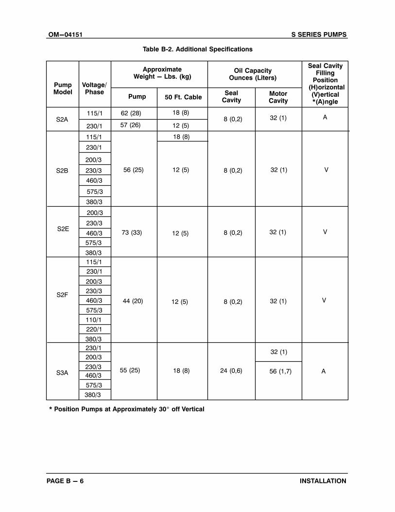
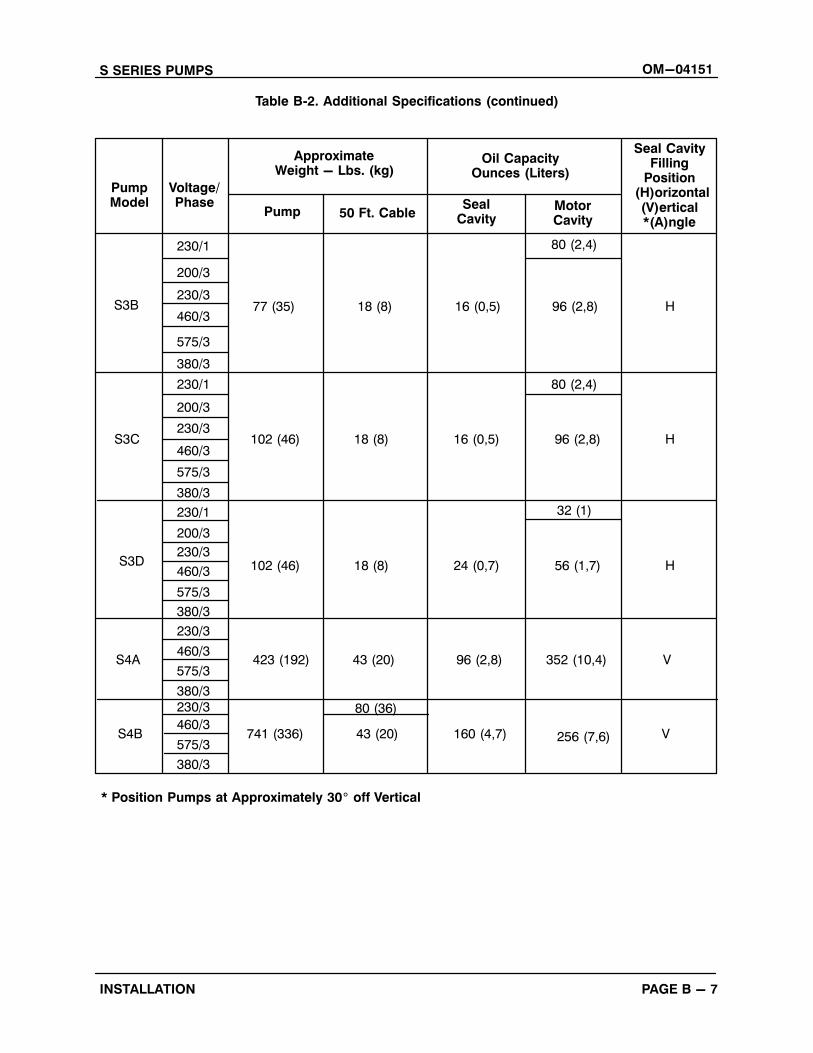
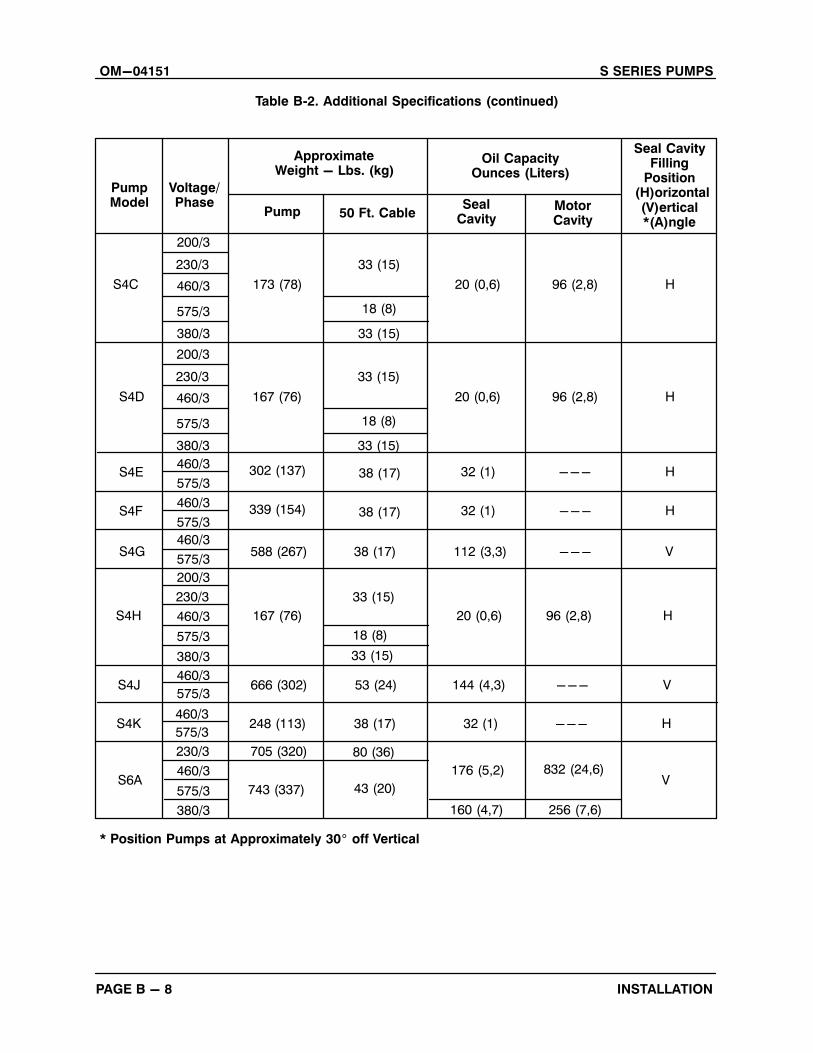
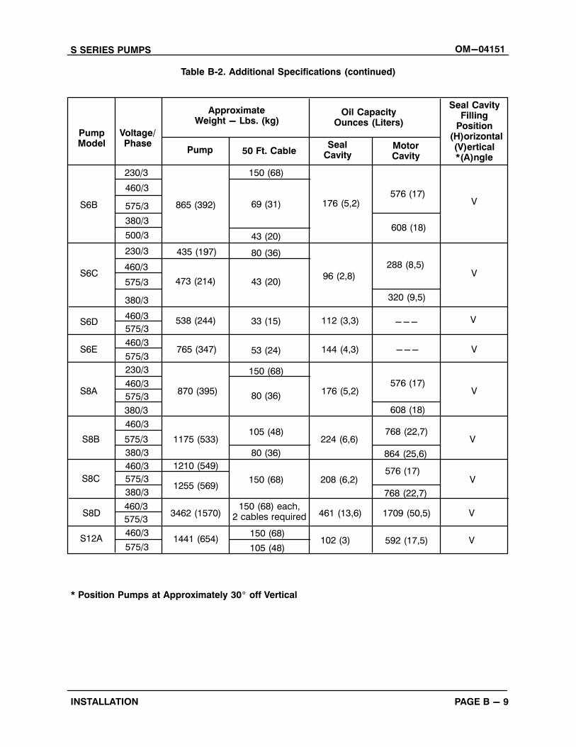
Due to differences in pump design, the quantity of
oil and manner in which oil is to be added to the
seal cavity varies between pump models. Refer to
Table B‐2 for oil capacities and positions for filling
the seal cavity in each pump. Motor cavities requir
ing lubrication should always be positioned verti
cally for filling. Refer to LUBRICATION, Section C
for lubrication specifications and intervals.
PUMP INSTALLATION
Pump Motor Specifications
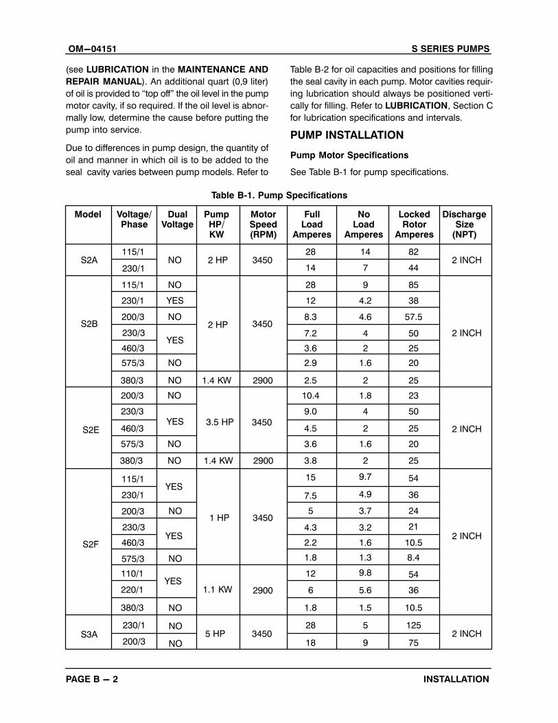
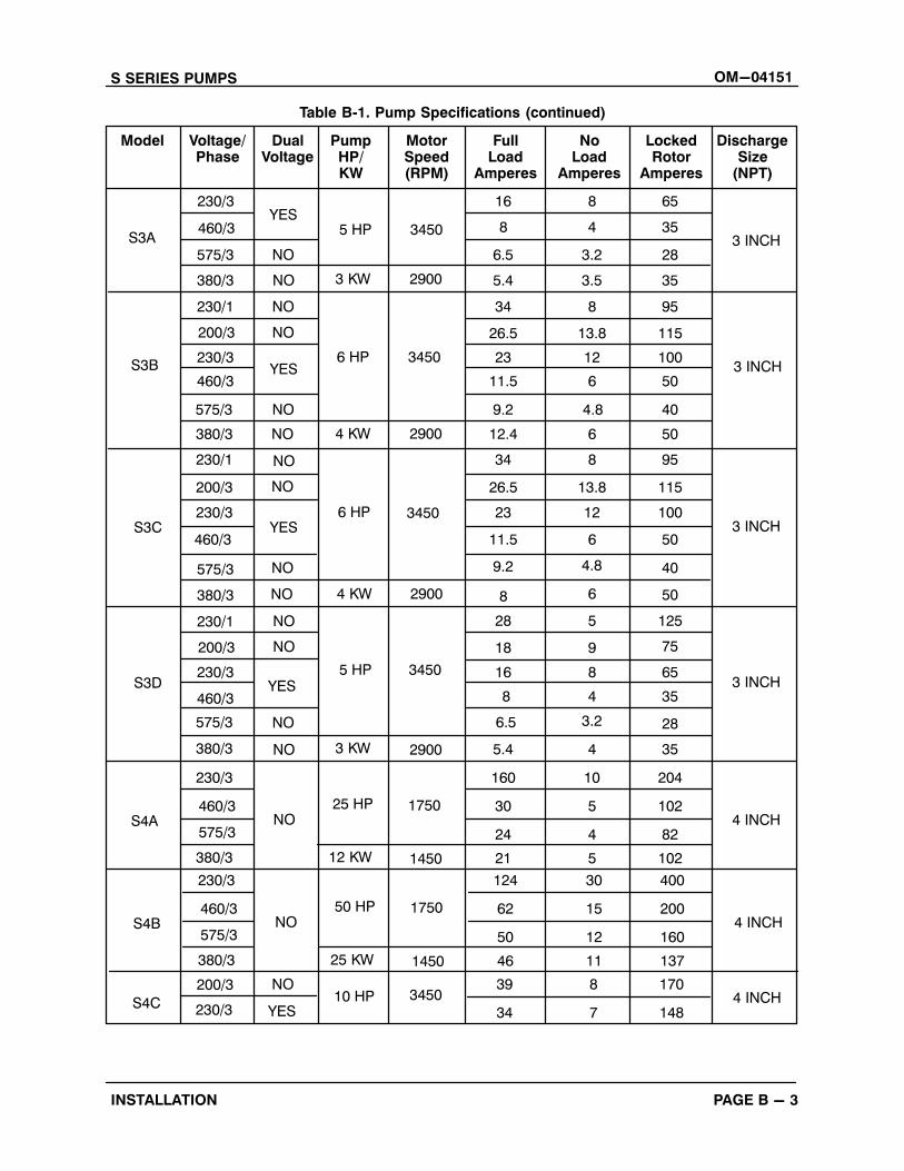
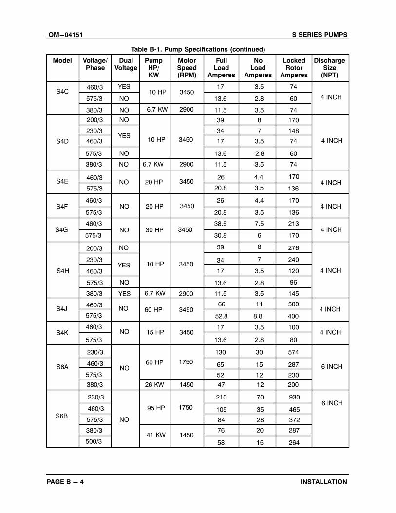
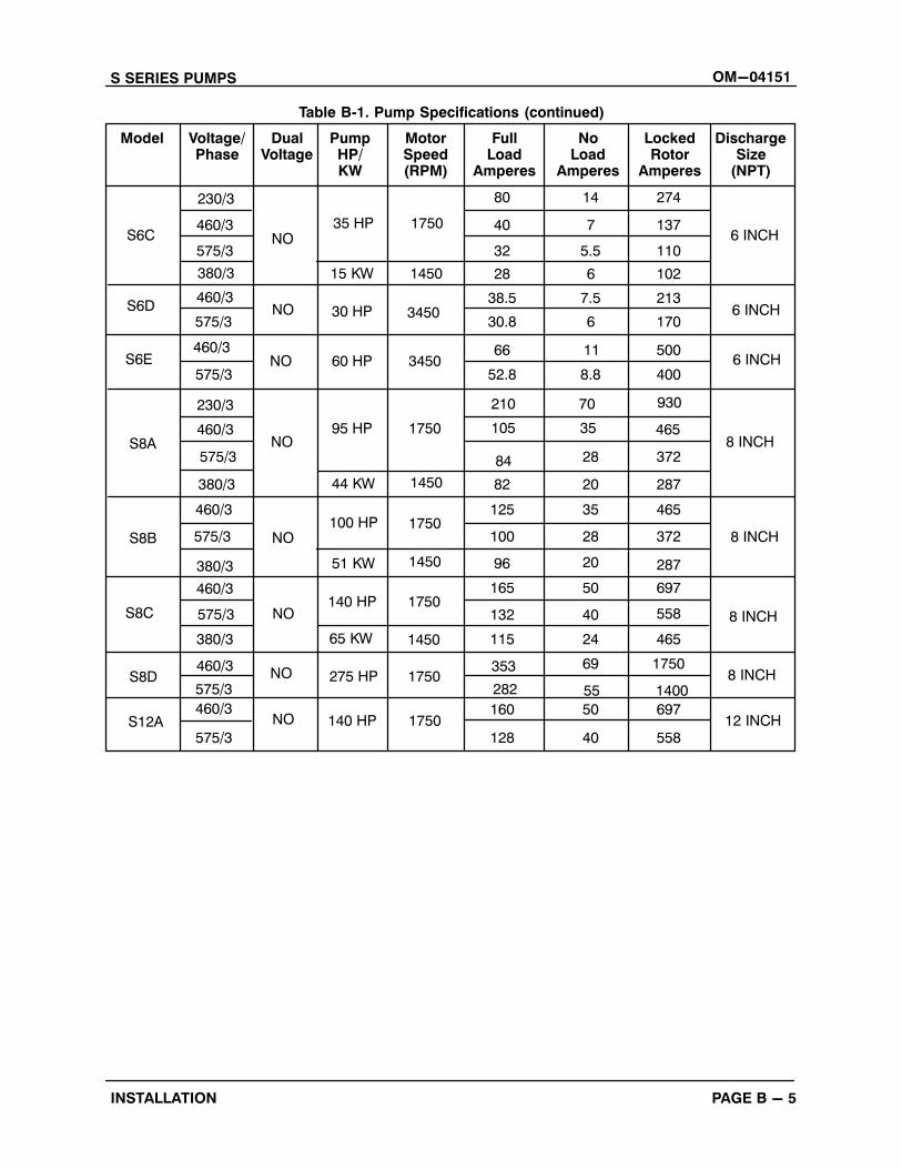
See Table B‐1 for pump specifications.
Table B‐1. Pump Specifications
DualVoltage
LockedRotor
Amperes
PumpHP/KW
MotorSpeed(RPM)
FullLoad
Amperes
NoLoad
Amperes
DischargeSize
(NPT)
Model Voltage/Phase
S2A115/1
NO 2 HP 345028
14
14
7
82
442 INCH
S2B
230/1
115/1
230/1
200/3
230/3
460/3
575/3
380/3
NO
YES
NO
YES
NO
NO
2 HP 3450
1.4 KW 2900
2 INCH
28
12
8.3
7.2
3.6
2.9
2.5
9
4.2
4.6
4
2
1.6
2
85
38
57.5
50
25
20
25
200/3
230/3
460/3
575/3
380/3
NO
YES
NO
NO
S2E
1.4 KW
3.5 HP 3450
2900
10.4
9.0
4.5
3.6
3.8
2 INCH
1.8
4
2
1.6
2
23
50
25
20
25
115/1
230/1
200/3
230/3
460/3
575/3
110/1
220/1
380/3
S2F
S3A230/1
200/3
NO
NO
2 INCH
2 INCH
YES
YES
YES
NO
NO
NO
1 HP
1.1 KW
5 HP
2900
3450
3450
15
7.5
5
4.3
2.2
1.8
12
6
1.8
28
18
9.7
4.9
3.7
3.2
1.6
1.3
9.8
5.6
1.5
5
9
54
36
24
21
10.5
8.4
54
36
10.5
125
75
S SERIES PUMPS OM-04151
PAGE B - 3INSTALLATION
Table B‐1. Pump Specifications (continued)
DualVoltage
LockedRotor
Amperes
PumpHP/KW
MotorSpeed(RPM)
FullLoad
Amperes
NoLoad
Amperes
DischargeSize
(NPT)
Model Voltage/Phase
S3A
230/3YES
5 HP 3450
16
8
8
4
65
353 INCH
S3B
460/3
575/3
380/3
230/1
200/3
230/3
460/3
575/3
NO
NO
NO
YES
NO
NO
6 HP 3450
4 KW 2900
3 INCH
6.5
5.4
34
26.5
23
11.5
9.2
3.2
3.5
8
13.8
12
6
4.8
28
35
95
115
100
50
40
380/3
230/1
200/3
230/3
460/3
NO
YES
NO
NO
S3C6 HP 3450
2900
12.4
34
26.5
23
11.53 INCH
6
8
13.8
12
6
50
95
115
100
50
575/3
380/3
230/1
200/3
230/3
460/3
575/3
380/3
230/3
S3D
S4A460/3
575/3NO
3 INCH
4 INCH
NO
YES
NO
NO
NO
5 HP
3 KW
25 HP
2900
3450
1750
9.2
8
28
18
16
8
6.5
5.4
160
30
24
4.8
6
5
9
8
4
3.2
4
10
5
4
40
50
125
75
65
35
28
35
204
102
82
3 KW 2900
4 KW
NO
NO
380/3 12 KW 1450 21 5 102
230/3
S4B460/3
575/3NO 4 INCH
50 HP 1750
124
62
50
30
15
12
400
200
160
380/3 25 KW 1450 46 11 137
S4C
200/3
230/3
NO
YES10 HP 3450 4 INCH
39
34
8
7
170
148
OM-04151 S SERIES PUMPS
PAGE B - 4 INSTALLATION
Table B‐1. Pump Specifications (continued)
DualVoltage
LockedRotor
Amperes
PumpHP/KW
MotorSpeed(RPM)
FullLoad
Amperes
NoLoad
Amperes
DischargeSize
(NPT)
Model Voltage/Phase
S4CYES
10 HP 345017 3.5 74
4 INCH
S4D
460/3
575/3
380/3
200/3
230/3
460/3
575/3
NO
NO
YES
NO
NO
10 HP 3450
6.7 KW 2900
4 INCH
13.6
11.5
39
34
17
13.6
2.8
3.5
8
7
3.5
2.8
60
74
170
148
74
60
380/3
460/3
575/3
460/3
575/3
NO
NO
NO
NO
S4F
30 HP 3450
11.5
26
20.8
38.5
30.84 INCH
3.5
4.4
3.5
7.5
6
74
170
136
213
170
200/3
230/3
460/3
575/3
380/3
460/3
575/3
460/3
575/3
S4H
S4K
230/3
460/3NO
4 INCH
6 INCH
YES
NO
YES
NO
10 HP
15 HP
60 HP
2900
3450
1750
39
34
17
13.6
11.5
66
52.8
17
13.6
130
65
8
7
3.5
2.8
3.5
11
8.8
3.5
2.8
30
15
276
240
120
96
145
500
400
100
80
574
287
6.7 KW 2900
NO
575/3
26 KW 1450
52 12 230
380/3
S6A
230/3
460/3
NO
6 INCH95 HP 1750
47
210
105
12
70
35
200
930
465
575/3
41 KW
84 28 372S6B
380/3
500/31450
76
58
20
15
287
264
S4E460/3
575/3NO 20 HP 3450
26
20.8
4.4
3.5
170
1364 INCH
20 HP 3450 4 INCH
S4G
6.7 KW
S4J 60 HP 3450 4 INCH
3450 4 INCH
S SERIES PUMPS OM-04151
PAGE B - 5INSTALLATION
Table B‐1. Pump Specifications (continued)
DualVoltage
LockedRotor
Amperes
PumpHP/KW
MotorSpeed(RPM)
FullLoad
Amperes
NoLoad
Amperes
DischargeSize
(NPT)
Model Voltage/Phase
S6C35 HP 1750
80 14 274
6 INCH
S6D
230/3
460/3
575/3
380/3
460/3
575/3
NO
NO 30 HP 3450
60 HP 3450
6 INCH
40
32
28
38.5
30.8
66
7
5.5
6
7.5
6
11
137
110
102
213
170
500
575/3
575/3
380/3
460/3
575/3
NO
NO
NOS8A
100 HP 1750
52.8
84
82
125
100 8 INCH
8.8
28
20
35
28
400
372
287
465
372
380/3
460/3
575/3
380/3
460/3
575/3
460/3
575/3
S8B
S12A
8 INCH
NO
NO
140 HP
140 HP
1450
1750
96
165
132
115
353
282
160
128
20
50
40
24
69
55
50
40
287
697
558
465
1750
1400
697
558
15 KW 1450
NO
230/3
460/3 95 HP 1750
210
105
70
35
930
465
44 KW 1450
8 INCH
65 KW
S8D 275 HP 1750 8 INCH
1750 12 INCH
S6E460/3
6 INCH
51 KW 1450
S8C
OM-04151 S SERIES PUMPS
PAGE B - 6 INSTALLATION
Table B‐2. Additional Specifications
PumpModel
Voltage/Phase
S2B
230/1
115/1
230/1
200/3
230/3
380/3
200/3
230/3
460/3
575/3
380/3
115/1
230/1
380/3
460/3
575/3
110/1
S2F
230/1
200/3
S3A230/3
460/3
575/3
380/3
460/3
575/3
S2E
ApproximateWeight - Lbs. (kg)
Oil CapacityOunces (Liters)
Seal CavityFilling
Position (H)orizontal
(V)ertical*(A)ngle
Pump 50 Ft. CableSeal
CavityMotorCavity
115/1S2A 8 (0,2) 32 (1)
62 (28)
57 (26)
18 (8)
12 (5)
A
18 (8)
56 (25) 12 (5) 8 (0,2) 32 (1) V
73 (33) 12 (5) 8 (0,2) 32 (1) V
200/3
230/3
220/1
44 (20) 12 (5) 8 (0,2) 32 (1) V
55 (25) 18 (8) 24 (0,6)
32 (1)
56 (1,7) A
* Position Pumps at Approximately 30� off Vertical
S SERIES PUMPS OM-04151
PAGE B - 7INSTALLATION
Table B‐2. Additional Specifications (continued)
PumpModel
Voltage/Phase
S3C
200/3
230/3
460/3
575/3
380/3
230/3
460/3
575/3
380/3
230/1
200/3
230/3
460/3
380/3
230/3
460/3
575/3
S3D
S4A
230/3
460/3
575/3
380/3
230/1
200/3
ApproximateWeight - Lbs. (kg)
Oil CapacityOunces (Liters)
Seal CavityFilling
Position (H)orizontal
(V)ertical*(A)ngle
Pump 50 Ft. CableSeal
CavityMotorCavity
230/1
S3B
80 (2,4)
77 (35) 18 (8) 16 (0,5) 96 (2,8) H
102 (46) 18 (8) 16 (0,5) 96 (2,8) H
575/3
380/3
423 (192) 43 (20) 96 (2,8) 352 (10,4) V
741 (336) 43 (20) 160 (4,7) 256 (7,6)
80 (36)
V
* Position Pumps at Approximately 30� off Vertical
80 (2,4)
102 (46) 18 (8) 24 (0,7) 56 (1,7) H
32 (1)
S4B
OM-04151 S SERIES PUMPS
PAGE B - 8 INSTALLATION
Table B‐2. Additional Specifications (continued)
PumpModel
Voltage/Phase
200/3
230/3
460/3
575/3
380/3
460/3
575/3
460/3
575/3
460/3
460/3
575/3
380/3
S4G
S4H
575/3
460/3
575/3
380/3
ApproximateWeight - Lbs. (kg)
Oil CapacityOunces (Liters)
Seal CavityFilling
Position (H)orizontal
(V)ertical*(A)ngle
Pump 50 Ft. CableSeal
CavityMotorCavity
S4C 173 (78)
18 (8)
20 (0,6) 96 (2,8) H
200/3
230/3
167 (76)
33 (15)
20 (0,6) 96 (2,8) H
743 (337) 43 (20)
176 (5,2) 832 (24,6)
80 (36)
V
* Position Pumps at Approximately 30� off Vertical
588 (267) 38 (17) 112 (3,3) --- V
S6A
33 (15)
33 (15)
200/3
230/3
460/3
575/3
380/3
S4D 167 (76)
18 (8)
20 (0,6) 96 (2,8) H
33 (15)
33 (15)
S4E 302 (137) 38 (17) 32 (1) --- H
460/3
575/3S4F 339 (154) 38 (17) 32 (1) --- H
18 (8)
33 (15)
S4J 666 (302) 53 (24) 144 (4,3) --- V
460/3
575/3S4K 248 (113) 38 (17) 32 (1) --- H
230/3 705 (320)
160 (4,7) 256 (7,6)
S SERIES PUMPS OM-04151
PAGE B - 9INSTALLATION
Table B‐2. Additional Specifications (continued)
PumpModel
Voltage/Phase
500/3
230/3
460/3
575/3
380/3
575/3
230/3
460/3
460/3
460/3
575/3
380/3
S8A
S8B
575/3
460/3
575/3
ApproximateWeight - Lbs. (kg)
Oil CapacityOunces (Liters)
Seal CavityFilling
Position (H)orizontal
(V)ertical*(A)ngle
Pump 50 Ft. CableSeal
CavityMotorCavity
S6B 865 (392) 69 (31) 176 (5,2)576 (17)
V
575/3
380/3
1175 (533)105 (48)
224 (6,6)768 (22,7)
V
105 (48)102 (3) 592 (17,5)
150 (68)V
* Position Pumps at Approximately 30� off Vertical
870 (395)
150 (68)
176 (5,2)576 (17)
V
S12A
43 (20)
150 (68)
230/3
460/3
575/3
380/3
460/3
S6C473 (214)
96 (2,8)
288 (8,5)V
33 (15)
43 (20)
S6D 538 (244) 112 (3,3) V
460/3
575/3S6E 765 (347) 53 (24) 144 (4,3) --- V
80 (36)
S8C1255 (569)
150 (68) 208 (6,2) V
460/3
575/3S8D 3462 (1570)
150 (68) each,2 cables required 461 (13,6) 1709 (50,5) V
1441 (654)
608 (18)
435 (197) 80 (36)
320 (9,5)
---
80 (36)
608 (18)
864 (25,6)
380/3
1210 (549)576 (17)
768 (22,7)
OM-04151 S SERIES PUMPS
PAGE B - 10 INSTALLATION
Pump Dimensions
For the approximate physical dimensions of your
pump, refer to the pump specification data sheet
or contact your Gorman‐Rupp distributor or the
Gorman‐Rupp Company.
PUMP INSTALLATION
When installing or servicing the pumpor controls, follow all requirements forthe installation of wiring or electricalequipment as outlined in the NationalElectric Code. Follow all safety requirements. Failure to observe these requirements could result in injury or death topersonnel.
Do not allow the free end of the powercable to enter the liquid being pumped.The free end of the cable must be kept dryto prevent liquid from wicking through thecable and into the motor.
NOTERefer to the performance curve in the Parts List
Manual when determining the most efficient piping
installation. The recommended maximum sub
mergence depth is 65 feet.
Lifting
Pump unit weights will vary depending on the
mounting and drive provided. Check the shipping
tag on the unit packaging for the actual weight, and
use lifting equipment with appropriate capacity.
Drain the pump and remove all customer‐installed
equipment such as suction and discharge hoses
or piping before attempting to lift existing, installed
units.
Refer to Table B-2 for the approximate maximum
weight for each pump.
Death or serious personal injury anddamage to the pump or componentscan occur if proper lifting proceduresare not observed. Make certain thathoists, chains, slings or cables are ingood working condition and of sufficient capacity and that they are positioned so that loads will be balancedand the pump or components will not bedamaged when lifting. Do not attempt tolift this pump by the motor or controlcables, or the piping. Attach proper lifting equipment to the lifting bail fitted onthe pump. Lift the pump or componentonly as high as necessary and keep personnel away from suspended objects.
Use Only Genuine Gorman-Rupp replacement parts. Failure to do so may create a hazard and damage the pump or diminish optimal pump performance. Anysuch hazard, damage or diminished performance is not covered by the warranty.
NOTEWhen appropriate recycling facilities are available,
the user should recycle components and fluids
when doing any routine maintenance / repairs and
also at the end of the pump’s useful life. All other
components and fluids shall be disposed of ac
cording to all applicable codes and regulations.
Positioning the Pump
NOTEBefore installing and operating the pump, check
the direction of impeller rotation to ensure that the
pump is properly wired at the control box. See IM
PELLER ROTATION, Section C.
S SERIES PUMPS OM-04151
PAGE B - 11INSTALLATION
The pump is designed to operate fully or partially
submerged. The rotating parts are oil lubricated,
and the motor is cooled by a constant flow of liquid
or air discharged through internal passages.
As a safeguard against rupture or explosion due to
heat, models equipped with oil‐lubricated motors
are fitted with a pressure relief valve which will open
if vapor pressure within the pump motor reaches a
critical point.
The pump will operate if positioned on its side, but
this is not recommended because the motor
torque could cause the pump to roll during opera
tion.
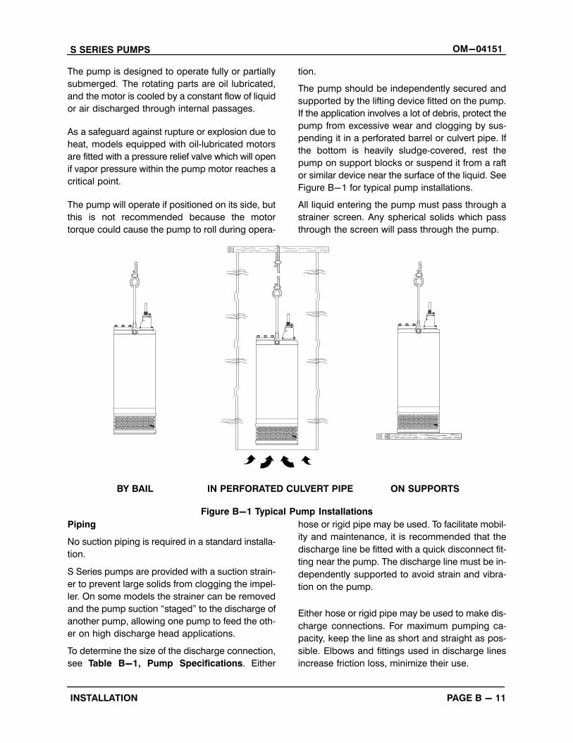
The pump should be independently secured and
supported by the lifting device fitted on the pump.
If the application involves a lot of debris, protect the
pump from excessive wear and clogging by sus
pending it in a perforated barrel or culvert pipe. If
the bottom is heavily sludge‐covered, rest the
pump on support blocks or suspend it from a raft
or similar device near the surface of the liquid. See
Figure B-1 for typical pump installations.
All liquid entering the pump must pass through a
strainer screen. Any spherical solids which pass
through the screen will pass through the pump.
BY BAIL IN PERFORATED CULVERT PIPE ON SUPPORTS
Figure B-1 Typical Pump Installations
Piping
No suction piping is required in a standard installa
tion.
S Series pumps are provided with a suction strain
er to prevent large solids from clogging the impel
ler. On some models the strainer can be removed
and the pump suction “staged” to the discharge of
another pump, allowing one pump to feed the oth
er on high discharge head applications.
To determine the size of the discharge connection,
see Table B-1, Pump Specifications. Either
hose or rigid pipe may be used. To facilitate mobil
ity and maintenance, it is recommended that the
discharge line be fitted with a quick disconnect fit
ting near the pump. The discharge line must be in
dependently supported to avoid strain and vibra
tion on the pump.
Either hose or rigid pipe may be used to make dis
charge connections. For maximum pumping ca
pacity, keep the line as short and straight as pos
sible. Elbows and fittings used in discharge lines
increase friction loss, minimize their use.
OM-04151 S SERIES PUMPS
PAGE B - 12 INSTALLATION
It is recommended that a check valve or throttling
valve be installed in the discharge line to control si
phoning or back flow when the pump is shut off.
ELECTRICAL CONNECTIONS
Install and operate this pump in accordance with the National Electrical Codeand all local codes. Have a qualifiedelectrician perform all checks and connections in this section.
Never attempt to alter the length of thepump motor cable or to repair it with asplice. The power cable and pump motor must be kept completely waterproof.Serious damage to the pump and injuryor death to personnel can result fromany alteration to the cable.
Control Box Installation
The pump is designed to be operatedthrough the control box furnished withthe pump. The control box providesoverload protection and power control.Do not connect the pump motor directlyto the incoming power lines.
The control box is a rainproof enclosure with a pad
lockable front cover. The enclosure is not de
signed to be watertight, and should not be sub
merged. Refer to the control box manual for enclo
sure dimensions and parts.
Secure the control vertically on a level surface,
above flood level. The box should be easily acces
sible to the operator, and located close enough to
the pump to avoid excessive voltage drop due to
cable length (see Pump Power Cable Connec
tion). After the box is installed, make certain the
front cover latches properly.
Failure to mount the control box verticallyon a level surface may affect operation ofthe pump controls.
Dual Voltage Usage
Some pumps are powered by a dual‐voltage motor
for utilization with high or low voltage. The motor
was originally wired and shipped from the factory
for use with the voltage indicated as “Factory
Wired” on the pump's name plate. The name plate
also indicates the dual voltage pertaining to this
motor. If the alternate voltage must be utilized, con
trol box modifications and/or certain wiring
changes are required.
The control box assembly provided with this pump
has been designed to accommodate only the volt
age indicated on the front of the box. This voltage
coincides with the “Factory Wired” voltage of the
motor. If the alternate voltage is utilized, the control
box must be replaced with another box designed
for the appropriate voltage. Alternate voltage con
trol boxes are shown in the Parts List Manual under
Pump Options.
Dual voltage pumps are wired at the factory only for the voltage shown on thename plate. Make certain that the control box voltage matches the pump voltage before using. If the pump voltage ischanged, the pump name plate must bechanged and a new control box must beinstalled. Do not run the pump if the voltages do not match; otherwise, the pumpwarranty will be negated, and damageto the pump, and injury or death to personnel can result.
The motor wiring must also be changed before uti
lizing alternate voltage. For detailed instructions on
disassembly and reassembly of the terminal hous
ing, see Terminal Housing and Power Cable Dis
assembly and Terminal Housing and Power
S SERIES PUMPS OM-04151
PAGE B - 13INSTALLATION
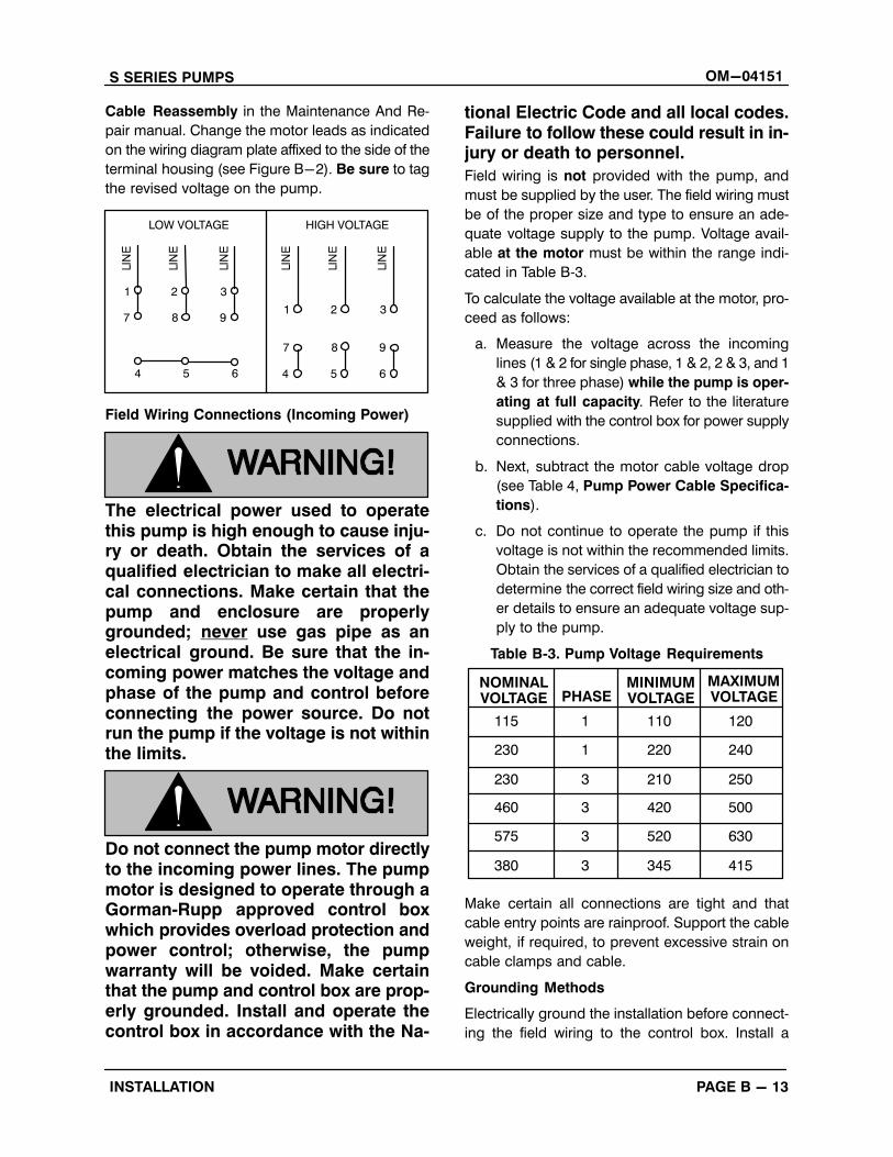
Cable Reassembly in the Maintenance And Re
pair manual. Change the motor leads as indicated
on the wiring diagram plate affixed to the side of the
terminal housing (see Figure B-2). Be sure to tag
the revised voltage on the pump.
LOW VOLTAGE HIGH VOLTAGE
1 2 3
7 8 9
4 5 6 4 5 6
7 8 9
1 2 3
Field Wiring Connections (Incoming Power)
The electrical power used to operatethis pump is high enough to cause injury or death. Obtain the services of aqualified electrician to make all electrical connections. Make certain that thepump and enclosure are properlygrounded; never use gas pipe as anelectrical ground. Be sure that the incoming power matches the voltage andphase of the pump and control beforeconnecting the power source. Do notrun the pump if the voltage is not withinthe limits.
Do not connect the pump motor directlyto the incoming power lines. The pumpmotor is designed to operate through aGorman‐Rupp approved control boxwhich provides overload protection andpower control; otherwise, the pumpwarranty will be voided. Make certainthat the pump and control box are properly grounded. Install and operate thecontrol box in accordance with the Na
tional Electric Code and all local codes.Failure to follow these could result in injury or death to personnel.
Field wiring is not provided with the pump, and
must be supplied by the user. The field wiring must
be of the proper size and type to ensure an ade
quate voltage supply to the pump. Voltage avail
able at the motor must be within the range indi
cated in Table B‐3.
To calculate the voltage available at the motor, pro
ceed as follows:
a. Measure the voltage across the incoming
lines (1 & 2 for single phase, 1 & 2, 2 & 3, and 1
& 3 for three phase) while the pump is oper
ating at full capacity. Refer to the literature
supplied with the control box for power supply
connections.
b. Next, subtract the motor cable voltage drop
(see Table 4, Pump Power Cable Specifica
tions).
c. Do not continue to operate the pump if this
voltage is not within the recommended limits.
Obtain the services of a qualified electrician to
determine the correct field wiring size and oth
er details to ensure an adequate voltage sup
ply to the pump.
Table B‐3. Pump Voltage Requirements
NOMINALVOLTAGE
3
3
230
460
210
420
250
500
PHASEMINIMUMVOLTAGE
MAXIMUMVOLTAGE
1230 220 240
575 3 520 630
1115 110 120
380 3 345 415
Make certain all connections are tight and that
cable entry points are rainproof. Support the cable
weight, if required, to prevent excessive strain on
cable clamps and cable.
Grounding Methods
Electrically ground the installation before connect
ing the field wiring to the control box. Install a
OM-04151 S SERIES PUMPS
PAGE B - 14 INSTALLATION
grounding terminal to the enclosure and connect
it to a properly embedded electrode.
The material used for the electrode must be an ex
cellent conductor of electricity, such as copper. If
iron or steel is used, it must be galvanized or other
wise metal plated to resist corrosion. Do not coat
the electrode with any material of poor conductiv
ity, such as paint or plastic.
The electrode must conform to the recommenda
tions of N.E.C. ARTICLE 250. Follow all installation
requirements of the N.E.C., and all applicable
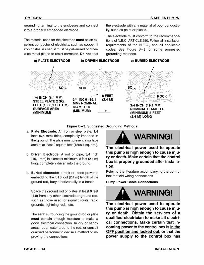
codes. See Figure B-3 for some suggested
grounding methods.
ROCK8 FEET(2,4 M)3/4 INCH (19,1
MM) NOMINALDIAMETER(MINIMUM)
3/4 INCH (19,1 MM)NOMINAL DIAMETER(MINIMUM) 8 FEET(2,4 M) LONG
SOILSOILSOIL
1/4 INCH (6,4 MM)STEEL PLATE 2 SQ.FEET (1858,1 SQ. CM)SURFACE AREA(MINIMUM)
a) PLATE ELECTRODE b) DRIVEN ELECTRODE c) BURIED ELECTRODE
Figure B-3. Suggested Grounding Methods
a. Plate Electrode: An iron or steel plate, 1/4
inch (6,4 mm) thick, completely impeded in
the ground. The plate must present a surface
area of at least 2 square feet (1858,1 sq. cm.).
b. Driven Electrode: A rod or pipe, 3/4 inch
(19,1 mm) in diameter minimum, 8 feet (2,4 m)
long, completely driven into the ground.
c. Buried electrode: If rock or stone prevents
embedding the full 8 foot (2,4 m) length of the
ground rod, bury it horizontally in a trench.
Space the ground rod or plates at least 6 feet
(1,8) from any other electrode or ground rod,
such as those used for signal circuits, radio
grounds, lightning rods, etc.
The earth surrounding the ground rod or plate
must contain enough moisture to make a
good electrical connection. In dry or sandy
areas, pour water around the rod, or consult
qualified personnel to devise a method of im
proving the connections.
The electrical power used to operatethis pump is high enough to cause injury or death. Make certain that the controlbox is properly grounded after installation.
Refer to the literature accompanying the control
box for field wiring connections.
Pump Power Cable Connections
The electrical power used to operatethis pump is high enough to cause injury or death. Obtain the services of aqualified electrician to make all electrical connections. Make certain that incoming power to the control box is in theOFF position and locked out, or that thepower supply to the control box has
S SERIES PUMPS OM-04151
PAGE B - 15INSTALLATION
been otherwise cut off and locked out,
before connecting power or accessory
cables.
The pump is provided with a 50 ft. (15,2 m) power
cable (see Table B-4 for standard power cable
specifications). If a longer cable is required, an op
tional cable assembly must be ordered from the
factory. Splicing of the power cable is not recom
mended by the Gorman‐Rupp Company due to
safety and warranty considerations.
Never attempt to alter the length or repair any power cable with a splice. Thepump motor and cable must be completely waterproof. Injury or death mayresult from alternations.
OM-04151 S SERIES PUMPS
PAGE B - 16 INSTALLATION
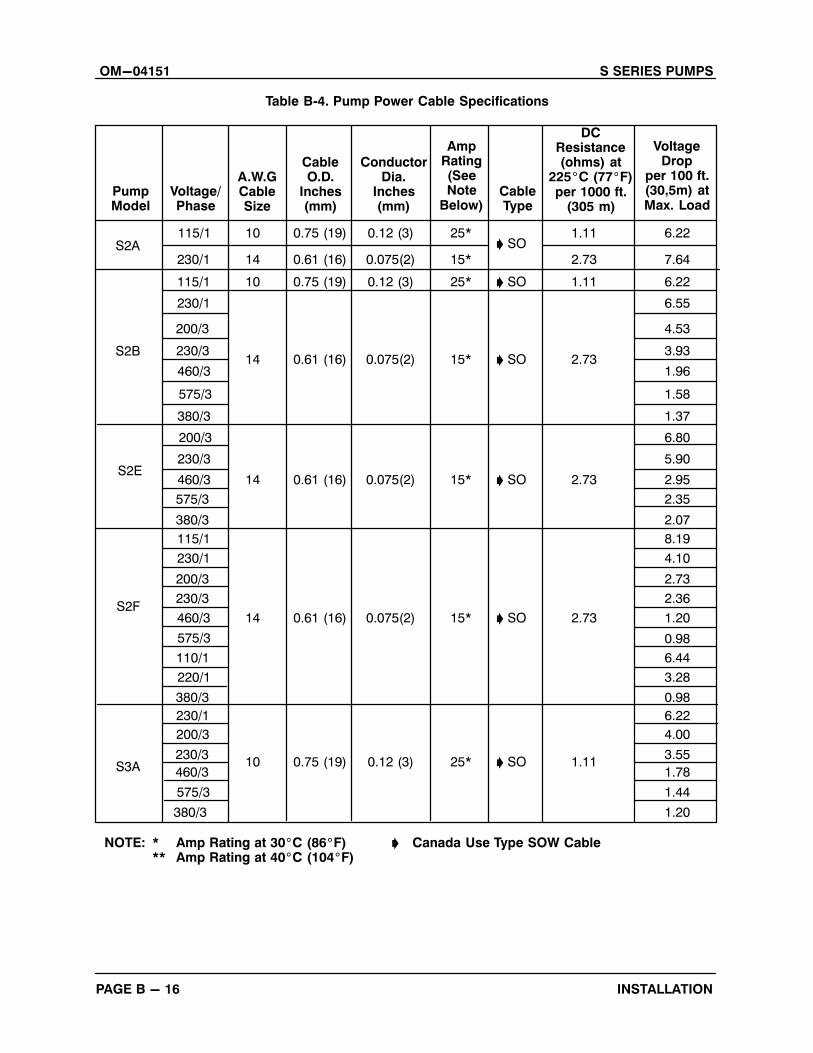
Table B‐4. Pump Power Cable Specifications
PumpModel
Voltage/Phase
S2B
230/1
115/1
230/1
200/3
230/3
380/3
200/3
230/3
460/3
575/3
380/3
115/1
230/1
380/3
460/3
575/3
110/1
S2F
230/1
200/3
S3A230/3
460/3
575/3
380/3
460/3
575/3
S2E
A.W.GCableSize
ConductorDia.
Inches(mm)
DCResistance(ohms) at
225�C (77�F)per 1000 ft.
(305 m)
CableO.D.
Inches(mm)
AmpRating(SeeNote
Below)CableType
115/1S2A
10
14
200/3
230/3
220/1
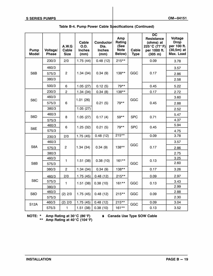
NOTE: * Amp Rating at 30�C (86�F) � Canada Use Type SOW Cable** Amp Rating at 40�C (104�F)
0.75 (19) 0.12 (3)
VoltageDrop
per 100 ft.(30,5m) atMax. Load
25*� SO
1.11 6.22
2.73 7.640.61 (16) 0.075(2) 15*
10 0.75 (19) 0.12 (3) 25* � SO 1.11 6.22
14 � SO 2.730.61 (16) 0.075(2) 15*
6.55
4.53
3.93
1.96
1.58
1.37
14 � SO 2.730.61 (16) 0.075(2) 15*
14 � SO 2.730.61 (16) 0.075(2) 15*
10 0.75 (19) 0.12 (3) 25* � SO 1.11
6.80
5.90
2.95
2.35
2.07
8.19
4.10
2.73
2.36
1.20
0.98
6.44
3.28
0.98
6.22
4.00
3.55
1.78
1.44
1.20
S SERIES PUMPS OM-04151
PAGE B - 17INSTALLATION
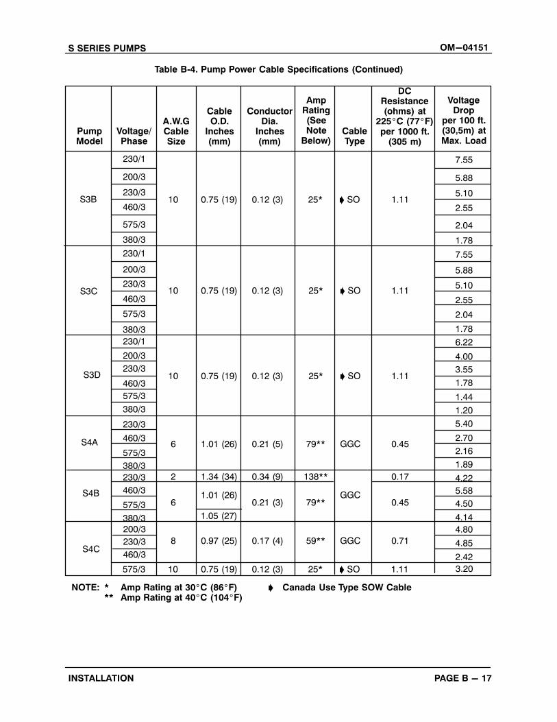
Table B‐4. Pump Power Cable Specifications (Continued)
PumpModel
Voltage/Phase
A.W.GCableSize
ConductorDia.
Inches(mm)
DCResistance(ohms) at
225�C (77�F)per 1000 ft.
(305 m)
CableO.D.
Inches(mm)
AmpRating(SeeNote
Below)CableType
10
NOTE: * Amp Rating at 30�C (86�F) � Canada Use Type SOW Cable** Amp Rating at 40�C (104�F)
0.75 (19) 0.12 (3)
VoltageDrop
per 100 ft.(30,5m) atMax. Load
25* � SO 1.11
7.55
5.88
10 0.75 (19) 0.12 (3) 25* � SO 1.11
5.10
2.55
2.04
1.78
7.55
5.88
5.10
6 1.01 (26) 0.21 (5) 79** GGC 0.45
2.55
2.04
1.78
6.22
4.00
3.55
1.78
1.44
1.20
5.40
2.70
2.16
1.89
4.22
5.58
4.50
4.14
4.80
4.85
2.42
S3C
200/3
230/3
460/3
575/3
380/3
230/3
460/3
575/3
380/3
230/1
200/3
230/3
460/3
380/3
230/3
460/3
575/3
S3D
S4A
230/3
460/3
575/3
380/3
230/1
200/3
230/1
S3B
575/3
380/3
S4B
10 0.75 (19) 0.12 (3) 25* � SO 1.11
2 1.34 (34) 0.34 (9) 138**
GGC
0.17
61.01 (26)
0.21 (3) 79** 0.45
1.05 (27)
S4C230/3
460/3
575/3
200/3
8 0.97 (25) 0.17 (4) 59** GGC 0.71
10 0.75 (19) 0.12 (3) 25* � SO 1.11 3.20
OM-04151 S SERIES PUMPS
PAGE B - 18 INSTALLATION
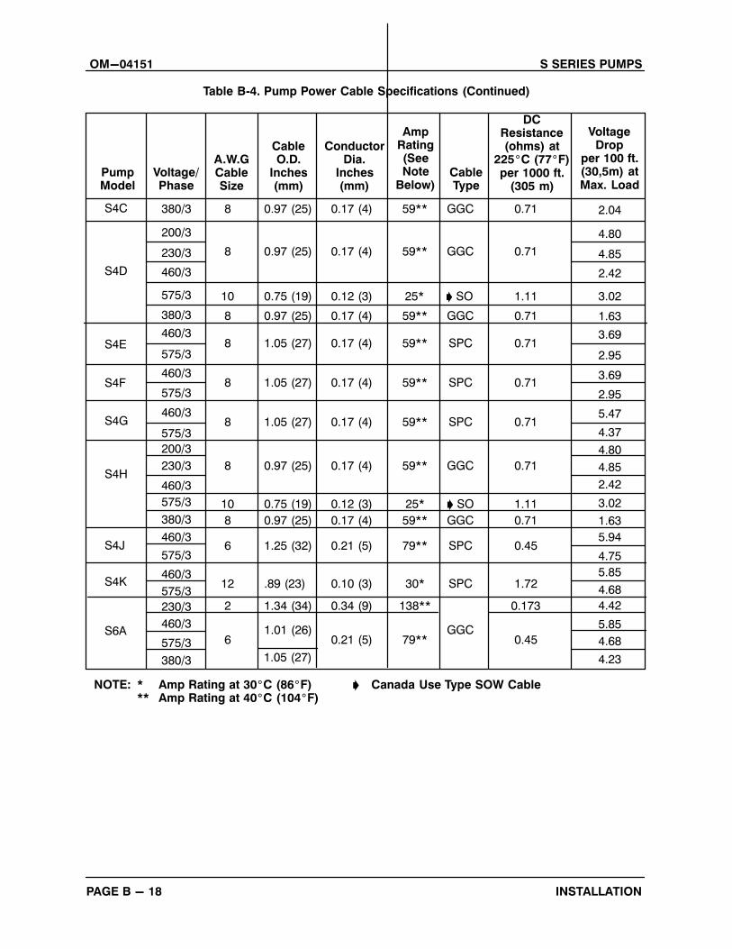
Table B‐4. Pump Power Cable Specifications (Continued)
PumpModel
Voltage/Phase
A.W.GCableSize
ConductorDia.
Inches(mm)
DCResistance(ohms) at
225�C (77�F)per 1000 ft.
(305 m)
CableO.D.
Inches(mm)
AmpRating(SeeNote
Below)CableType
10
NOTE: * Amp Rating at 30�C (86�F) � Canada Use Type SOW Cable** Amp Rating at 40�C (104�F)
0.75 (19) 0.12 (3)
VoltageDrop
per 100 ft.(30,5m) atMax. Load
25* � SO 1.11
2.04
4.80
4.85
2.42
3.02
1.63
3.69
2.95
3.69
12 .89 (23) 0.10 (3) 30* SPC 1.72
2.95
5.47
4.37
4.80
4.85
2.42
3.02
1.63
5.94
4.75
5.85
4.68
4.42
5.85
4.68
4.23
S4F
200/3
230/3
460/3
575/3
380/3
460/3
575/3
460/3
575/3
200/3
230/3
460/3
575/3
460/3
575/3
460/3
S4H
S4J
230/3
460/3
575/3
380/3
460/3
575/3
380/3S4C
575/3
380/3
S6A
10 0.75 (19) 0.12 (3) 25* � SO 1.11
2 1.34 (34) 0.34 (9) 138**
GGC
0.173
61.01 (26)
0.21 (5) 79** 0.45
1.05 (27)
8 0.97 (25) 0.17 (4) 59** GGC 0.71
S4D
8 0.97 (25) 0.17 (4) 59** GGC 0.71
8 0.97 (25) 0.17 (4) 59** GGC 0.71
S4E 8 1.05 (27) 0.17 (4) 59** SPC 0.71
8 1.05 (27) 0.17 (4) 59** SPC 0.71
S4G 8 1.05 (27) 0.17 (4) 59** SPC 0.71
8 0.97 (25) 0.17 (4) 59** GGC 0.71
8 0.97 (25) 0.17 (4) 59** GGC 0.71
6 1.25 (32) 0.21 (5) 79** SPC 0.45
S4K
S SERIES PUMPS OM-04151
PAGE B - 19INSTALLATION
Table B‐4. Pump Power Cable Specifications (Continued)
PumpModel
Voltage/Phase
A.W.GCableSize
ConductorDia.
Inches(mm)
DCResistance(ohms) at
225�C (77�F)per 1000 ft.
(305 m)
CableO.D.
Inches(mm)
AmpRating(SeeNote
Below)CableType
6
NOTE: * Amp Rating at 30�C (86�F) � Canada Use Type SOW Cable** Amp Rating at 40�C (104�F)
1.05 (27) 0.12 (5)
VoltageDrop
per 100 ft.(30,5m) atMax. Load
79** 0.45
3.78
3.57
2.86
2.58
5.22
2.72
3.60
2.88
2.52
2 1.34 (34) 0.34 (9) 138** 0.17
5.47
4.37
5.94
4.75
2.86
3.25
2.60
3.26
2.97
3.43
2.99
460/3
575/3
380/3
500/3
230/3
380/3
460/3
575/3
460/3
380/3
460/3
575/3
S6E
S8A
460/3
575/3
380/3
460/3
575/3
230/3
S6B
575/3
380/3
S8C
2/0 1.75 (45) 0.48 (12) 215**
GGC
0.09
1 1.51 (38) 0.38 (10) 161** 0.13
2/0 1.75 (44) 0.48 (12) 215** 0.09
2 1.34 (34) 0.34 (8) 138**
GGC
0.17
2 1.34 (34) 0.34 (9) 138** GGC 0.17
S6C6
1.05 (27)
0.21 (5) 79** 0.45
S6D 8 1.05 (27) 0.17 (4) 59** SPC 0.71
6 1.25 (32) 0.21 (5) 79** SPC 0.45
2 1.34 (34) 0.34 (9) 138**GGC
0.17
1 1.51 (38) 0.38 (10) 161**GGC
0.13S8B
1.01 (26)
460/3
230/3
575/3
2/0 1.75 (45) 0.48 (12) 215** 0.09 3.78
3.57
2.75
460/3
575/3S8D (2) 2/0
2.88
2.301.75 (45) 0.48 (12) 215** 0.09GGC
460/3
575/3S12A
1
3.04
3.521.51 (38) 0.38 (10) 161**
0.09GGC
0.13
(2) 2/0 1.75 (45) 0.48 (12) 215**
OM-04151 S SERIES PUMPS
PAGE B - 20 INSTALLATION
When necessary to change or connect the pump
power cable to the control box, make certain the in
coming power is OFF and LOCKED OUT, Make
certain the control box is PROPERLY GROUNDED
and that the electrical data on the control matches
the motor name plate data.
Connect the pump power cable to the control box
as shown in the wiring diagrams in the control box
manual. Use conduit or cable clamps to secure the
power cable to the control box. Make certain that
all connections are tight and that cable entry points
are rainproof.
NOTEThe power cable furnished with the pump includes
three electrical conductors (white, red, and black),
two grounding conductors (green) and one ground
check conductor (yellow). The yellow ground
check lead is used in conjunction with customer‐
supplied ground monitoring equipment. If this
equipment is not used, the yellow lead should be
used as a ground conductor.
Control Box Specifications
Any control box used to operate thepump must be approved by the Gorman‐Rupp Company for the application.
Motor Cable Grounding Test
Do not connect the pump control cableto the control box or incoming voltagebefore verifying the pump ground;otherwise, personnel will be exposed toserious injury or death.
Using a volt‐ohm meter, connect one lead to the
motor cable green/yellow ground lead. Connect
the other lead to an uninsulated point on the pump
body. The test circuit should close.
If the test circuit does not close, there is a defect in
the cable or motor which must be corrected.
Control Box Connections
This pump is shipped completely wired for the volt
age shown on the name plate, and is ready for op
eration through an approved control box.
Ground and wire the control box in accordance
with the instructions accompanying it.
NOTEFor reference, internal motor wiring connections
are shown in the Maintenance and Repair manual.
Liquid Level Devices
The standard pump is not furnished with a means
to automatically regulate liquid level. However, the
pump may be controlled to perform filling or dewa
tering functions by using either of the following op
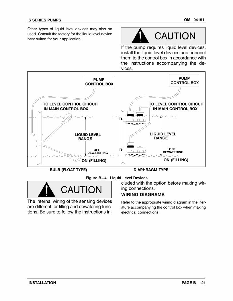
tional sensing devices (see Figure B-4):
� Diaphragm Type: two fixed‐position sen
sors (upper and lower) each contain a diaphragm which flexes with changes in liquidlevel, thus activating an enclosed miniatureswitch.
� Bulb (Float) Type: a bulb raises or lowers
(floats) with the liquid level, thus activating
an enclosed miniature switch.
Models under 6 horsepower require an additional
control box to incorporate liquid level controls. For
models over 6 horsepower, the circuitry may be
prewired as a factory option, or easily added to the
standard control box in the field by qualified per
sonnel. The unit is complete except for the remote
float switches. For installation and operation, see
the detailed instructions included with the optional
package.
Liquid level devices must be positioned farenough apart to allow 10 minutes betweenstarts. If the pump motor cycles more than6 starts per hour, it will over‐heat, resultingin damage to the motor windings or controlbox components.
S SERIES PUMPS OM-04151
PAGE B - 21INSTALLATION
Other types of liquid level devices may also be
used. Consult the factory for the liquid level device
best suited for your application.
If the pump requires liquid level devices,install the liquid level devices and connectthem to the control box in accordance withthe instructions accompanying the devices.
PUMPCONTROL BOX
LIQUID LEVELRANGE
ON (FILLING)
TO LEVEL CONTROL CIRCUIT
IN MAIN CONTROL BOX
BULB (FLOAT TYPE)
OFFDEWATERING
PUMPCONTROL BOX
TO LEVEL CONTROL CIRCUIT
IN MAIN CONTROL BOX
LIQUID LEVELRANGE
OFFDEWATERING
ON (FILLING)
DIAPHRAGM TYPE
Figure B-4. Liquid Level Devices
The internal wiring of the sensing devicesare different for filling and dewatering functions. Be sure to follow the instructions in
cluded with the option before making wiring connections.
WIRING DIAGRAMS
Refer to the appropriate wiring diagram in the liter
ature accompanying the control box when making
electrical connections.
S SERIES PUMPS OM-04151
PAGE C - 1OPERATION
OPERATION - SECTION C
GENERAL INFORMATION
Review all SAFETY information in Section A.
This pump is designed to handle mostnon‐volatile, non‐flammable liquids. Donot attempt to pump any liquids forwhich your pump is not approved, orwhich may damage the pump or endanger personnel as a result of pump failure. Consult the factory for specific application data.
Follow the instructions on all tags, labels and de
cals attached to the pump.
Pump Performance
Since operation of the pump motor is dependent upon the quality and performanceof the electrical controls, the pump warranty is valid only when controls have beenspecified or provided by The Gorman‐Rupp Company.
Refer to the pump Specification Data Sheet or the
accompanying Parts List Manual for the specific
performance for your pump.
Control Box
A control box is provided to facilitate operation of
the pump. It contains controls for starting and stop
ping the pump, and provides overload protection
for the pump motor. The pump control (for models
10 horsepower and up) may be equipped with an
optional automatic liquid level sensing device, in
which case those circuits are also contained within
the control box. Pump models under 6 horsepower
require an additional control box to incorporate liq
uid level controls.
The pump motor and control box are notdesigned to be explosion‐proof. Do notoperate in an explosive atmosphere.Any control box used to operate thepump must be approved by the Gorman‐Rupp Company for the application.Improper location of a non‐explosionproof control box could result in destruction of equipment, injury or deathto personnel.
See the operating instructions furnished with the
control box, and with other optional accessories
and controls, before attempting to start the pump.
PUMP OPERATION
Liquid Temperature and Overheating.
Overheated pumps can cause severeburns and injury. If the pump becomesoverheated:
1. Stop the pump immediately.2. Lock out the power to the control
panel to ensure that the pump willremain inoperative.
3. Allow the pump to completely coolif overheated.
4. Close the discharge valve (ifused).
5. Refer to instructions in this manualbefore restarting the pump.
Overheating can occur if the pump is misapplied;
if it is started more than 6 times within one hour; if
the temperature of the liquid being pumped ex
OM-04151 S SERIES PUMPS
PAGE C - 2 OPERATION
ceeds the temperature for which the pump was de
signed, if the control box fails to provide overload
or thermal protection, or if the pump is operated
against a closed discharge valve for an extended
period of time.
Do not start the pump more than 6 timesper hour. If the motor does not cool between starts it will overheat, resulting indamage to the motor windings.
As a safeguard against rupture or explosion due to
heat, models equipped with oil‐lubricated motors
are fitted with a pressure relief valve which will open
if vapor pressure within the pump motor reaches a
critical point. Always terminate power to the pump
and control before investigating pump or control
box problems.
Approach the pump cautiously after ithas been running. Although the motor iscooled by the liquid being pumped, normal operating temperatures can be highenough to cause burns. The temperature will be especially high if operatedagainst a closed discharge valve. Neveroperate against a closed dischargevalve for long periods of time.
If overheating does occur, stop the pump immedi
ately and allow it to cool before servicing it. Ap
proach any overheated pump cautiously.
Overheated pumps can cause severeburns and injuries. If overheating of thepump occurs:
1. Stop the pump immediately.
2. Ventilate the area.3. Allow the pump to completely cool.4. Check the temperature before ser
vicing.5. Vent the pump slowly and cau
tiously6. Refer to instructions in this manual
before restarting the pump.
Is so equipped, it is recommended that the pres
sure relief valve assembly be replaced at each
overhaul, or any time the pump motor overheats
and activates the valve. Never replace this valve
with a substitute which has not been specified or
provided by the Gorman‐Rupp Company.
Impeller Rotation
Check impeller rotation as follows before operation
to ensure that the impeller is rotating in the correct
direction.
While checking impeller rotation, securethe pump to prevent the power cable fromcoiling.
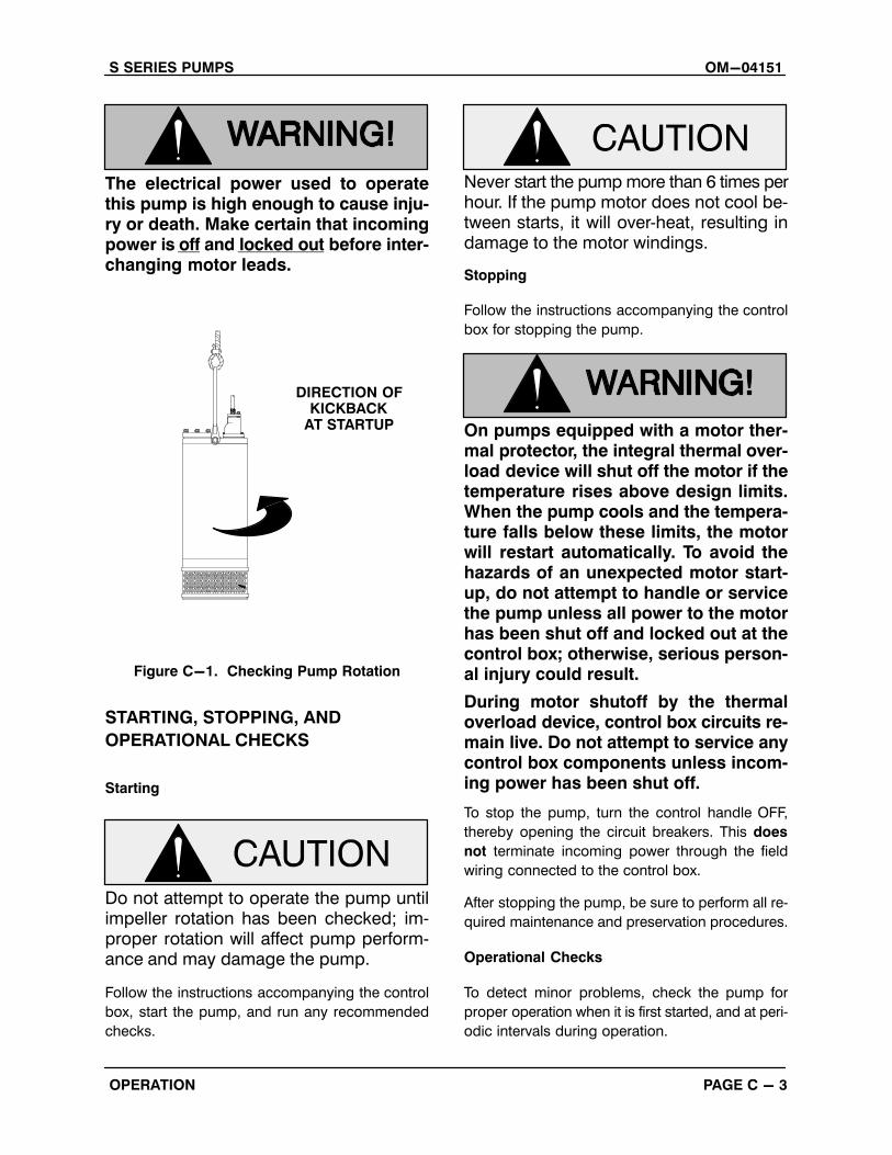
Suspend the pump from the lifting device fitted on
the pump. Apply power briefly and note the direc
tion of pump kickback. As viewed from the top, the
pump should kick in a counterclockwise direc
tion; this will indicate that impeller rotation is cor
rect.
If the pump kicks in a clockwise direction, impeller
rotation is incorrect. If the pump is powered by a
three‐phase motor, have a qualified electrician in
terchange the control box connections of any two
pump motor power leads. Re‐check pump kick
back; it should now be in a counterclockwise direc
tion.
If rotation is incorrect on a single‐phase motor, con
tact the factory before installing the pump.
S SERIES PUMPS OM-04151
PAGE C - 3OPERATION
The electrical power used to operatethis pump is high enough to cause injury or death. Make certain that incomingpower is off and locked out before interchanging motor leads.
DIRECTION OFKICKBACK
AT STARTUP
Figure C-1. Checking Pump Rotation
STARTING, STOPPING, AND
OPERATIONAL CHECKS
Starting
Do not attempt to operate the pump untilimpeller rotation has been checked; improper rotation will affect pump performance and may damage the pump.
Follow the instructions accompanying the control
box, start the pump, and run any recommended
checks.
Never start the pump more than 6 times perhour. If the pump motor does not cool between starts, it will over‐heat, resulting indamage to the motor windings.
Stopping
Follow the instructions accompanying the control
box for stopping the pump.
On pumps equipped with a motor thermal protector, the integral thermal overload device will shut off the motor if thetemperature rises above design limits.When the pump cools and the temperature falls below these limits, the motorwill restart automatically. To avoid thehazards of an unexpected motor start‐up, do not attempt to handle or servicethe pump unless all power to the motorhas been shut off and locked out at thecontrol box; otherwise, serious personal injury could result.
During motor shutoff by the thermaloverload device, control box circuits remain live. Do not attempt to service anycontrol box components unless incoming power has been shut off.
To stop the pump, turn the control handle OFF,
thereby opening the circuit breakers. This does
not terminate incoming power through the field
wiring connected to the control box.
After stopping the pump, be sure to perform all re
quired maintenance and preservation procedures.
Operational Checks
To detect minor problems, check the pump for
proper operation when it is first started, and at peri
odic intervals during operation.
OM-04151 S SERIES PUMPS
PAGE C - 4 OPERATION
To avoid serious damage to the pump,check for unusual noises or excessive vibration while the pump is running. If noiseor vibration is excessive, stop operationand refer to the troubleshooting chart in themaintenance and repair manual.
The suction inlet or impeller may become clogged
with debris. In some cases, stopping the pump
momentarily may backflush this blockage. If back
flushing does not clear the debris, remove the
pump from the sump or wet well and clear manu
ally.
Never introduce air or steam pressureinto the pump casing to remove a blockage. This could result in personal injuryor damage to the equipment. If backflushing is absolutely necessary, limitliquid pressure input to 50% of the maximum permissible operating pressureshown in the pump performance curve(refer to the accompanying Parts ListManual).
Check the pump for overheating. Overheating can
occur if the pump is misapplied, required to start
repeatedly, if the control box fails to provide over
load or thermal protection, or if the pump is oper
ated against a closed discharge valve for an ex
tended period of time.
Do not start the pump more than 6 timesper hour. If the motor does not cool between starts it will overheat, resulting indamage to the motor windings.
Check the oil level(s) as indicated in the following
LUBRICATION section.
COLD WEATHER PRESERVATION
Do not attempt to thaw the pump by using a torch or other source of flame. Thiscould damage gaskets, O‐rings or heatthe oil in the seal housing above criticaltemperatures, causing the pump to rupture or explode.
The pump will not freeze as long as the casing is
submerged in liquid. If the casing is not sub
merged, or if the liquid begins to freeze, remove the
pump from the sump or wet well and dry it thor
oughly. Run the pump for two or three minutes to
dry the inner walls.
If the pump does freeze while it is out of the liquid,
submerge it until thawed; if the liquid is near freez
ing, the pump must be submerged for an extended
period of time. Check thawing by starting the pump
and checking that the shaft rotates freely. If the
pump remains frozen, allow additional thawing
time before attempting to restart.
If submerging does not thaw the pump, move it
into a warm area until completely thawed.
LUBRICATION
Do not remove plates, covers, gauges,pipe plugs or fittings from an overheated pump. Vapor pressure within thepump can cause parts being disengaged to be ejected with great force. Allow the pump to completely cool beforeservicing.
On a new pump, check the oil level in both seal and
motor cavities (if oil lubricated) before initial start
up, and drain and replace the oil after the first 200
hours of operation. Following this, check the oil lev
el in the seal cavity after the first two weeks of op
S SERIES PUMPS OM-04151
PAGE C - 5OPERATION
eration, and every month thereafter. Check the mo
tor lubrication level any time the pressure relief
valve is activated, and replace the oil annually.
Before installing or removing the lubrication
plug(s), always clean the area around the plug(s)
to prevent contamination.
Draining Oil
Refer to the Parts List Manual for drain plug loca
tion.
For the smaller pump, lay the pump horizontal on
a flat work surface with the seal cavity drain plug
facing up. Remove the drain plug slowly to release
any pressure. Install a short pipe nipple in the hole.
Place a clean container under the plug and roll the
pump on its side to drain the seal housing.
For the larger pump, remove the drain plug slowly
to release any pressure. Install a short pipe nipple
in the hole. Place a clean container under the plug
and using a hoist, tilt the pump at an angle of
approximately 60 degrees.
If the motor is oil‐cooled, repeat the procedure for
the motor housing oil.
Condition Of Oil
Check the condition of the oil drained from the
pump. Clear oil indicates that the pump seal(s) are
functioning properly. If the oil is milky or contains
a small amount of water, it must be changed.
If the oil contains a large amount of water, it must
be changed, and the seal(s) must be checked be
fore the pump is put back in operation (refer to the
Maintenance and Repair Manual).
Adding Oil
Due to differences in pump design, the quantity of
oil and manner in which oil is to be added to the
seal cavity varies between pump models. Refer to
Table B-2 in INSTALLATION for oil capacities and
positions for filling the seal cavity in each pump.
Motor cavities requiring lubrication should always
be positioned vertically for filling.
The grade of lubricant used is critical to the opera
tion of this pump. Use premium quality submers
ible pump oil as specified in the following table. Oil
must be stored in a clean, tightly closed container
in a reasonably dry environment.
When lubricating the seal cavity, remove the lu
brication plug as indicated in Draining Oil, and
position the pump as indicated in Table B-2. Add
premium quality submersible pump oil through
this plug hole. If the pump is to be positioned verti
cally or at an angle, fill the cavity to the bottom of
the plug hole. If the pump is to be positioned hori
zontally, completely fill the cavity.
Install and tighten the lubrication plug.
When lubricating the motor cavity, add oil through
the hole for the pressure relief valve. If the pump is
equipped with a motor lubricant level plug, remove
this plug and fill the cavity until oil escapes through
the hole. If the pump is not equipped with a motor
lubricant level plug, fill the cavity to the top of the
hole.
Reinstall the pressure relief valve.
OM-04151 S SERIES PUMPS
PAGE C - 6 OPERATION
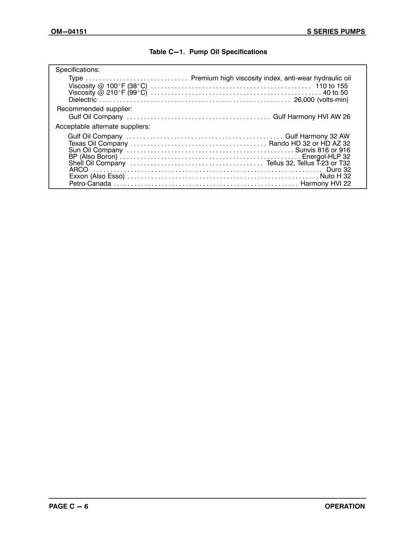
Table C-1. Pump Oil Specifications
Specifications:
Type Premium high viscosity index, anti‐wear hydraulic oil. . . . . . . . . . . . . . . . . . . . . . . . . . . . . .Viscosity @ 100�F (38�C) 110 to 155. . . . . . . . . . . . . . . . . . . . . . . . . . . . . . . . . . . . . . . . . . . . . . .
Dielectric 26,000 (volts‐min). . . . . . . . . . . . . . . . . . . . . . . . . . . . . . . . . . . . . . . . . . . . . . . . . . . . . . . .
Acceptable alternate suppliers:
Gulf Oil Company Gulf Harmony HVI AW 26. . . . . . . . . . . . . . . . . . . . . . . . . . . . . . . . . . . . . . . . . .
Texas Oil Company Rando HD 32 or HD AZ 32. . . . . . . . . . . . . . . . . . . . . . . . . . . . . . . . . . . . . . . .Sun Oil Company Sunvis 816 or 916. . . . . . . . . . . . . . . . . . . . . . . . . . . . . . . . . . . . . . . . . . . . . . . . .BP (Also Boron) Energol‐HLP 32. . . . . . . . . . . . . . . . . . . . . . . . . . . . . . . . . . . . . . . . . . . . . . . . . . . . .Shell Oil Company Tellus 32, Tellus T‐23 or T32. . . . . . . . . . . . . . . . . . . . . . . . . . . . . . . . . . . . . . .
Viscosity @ 210�F (99�C) 40 to 50. . . . . . . . . . . . . . . . . . . . . . . . . . . . . . . . . . . . . . . . . . . . . . . . . .
Recommended supplier:
Gulf Oil Company Gulf Harmony 32 AW. . . . . . . . . . . . . . . . . . . . . . . . . . . . . . . . . . . . . . . . . . . . . .
ARCO Duro 32. . . . . . . . . . . . . . . . . . . . . . . . . . . . . . . . . . . . . . . . . . . . . . . . . . . . . . . . . . . . . . . . . . .Exxon (Also Esso) Nuto H 32. . . . . . . . . . . . . . . . . . . . . . . . . . . . . . . . . . . . . . . . . . . . . . . . . . . . . . . .Petro‐Canada Harmony HVI 22. . . . . . . . . . . . . . . . . . . . . . . . . . . . . . . . . . . . . . . . . . . . . . . . . . . . . .

For Warranty Information, Please Visitwww.grpumps.com/warranty
or call:U.S.: 419-755-1280
Canada: 519-631-2870International: +1-419-755-1352
GORMAN‐RUPP PUMPS