Š Aerial Cams - jiscco.com · Ease of spring replacement from back of cam; the cam base...
52
Aerial Cams
Transcript of Š Aerial Cams - jiscco.com · Ease of spring replacement from back of cam; the cam base...
� Aerial Cams
2
TABLE OF CONTENTS
Introduction ..................................................... 2
General Information ......................................... 3
50 Series Cams .............................................. 4
75 Series Cams .............................................. 8
125-150 Series Cams .................................... 12
175-200 Series Cams .................................... 16
250-300 Series Cams .................................... 20
Installation Instructions.................................. 24
Installation Tool ............................................. 25
!!!!! Ease of spring replacement from back of cam; the cam base incorporates a safety restraint system toretain the slide during spring removal
!!!!! High quality materials used throughout, including high-strength steel castings for major components
!!!!! All wear areas are double-plated with self-lubricated wear plates to reduce maintenance andaccommodate high production volumes
!!!!! Three Return Spring Kit options are available: mechanical ISO spring, combination mechanical/nitrogen springs and nitrogen spring
!!!!! Pentahedron design ensures smooth and stable slide movement on 125 through 300 Series Cams
!!!!! Urethane bumper cushion on slide return; Optional hydraulic shock absorber available
!!!!! Mounting/locating provisions include both square keys and dowel holes
!!!!! Meets or exceeds all of �NAAMS� cam requirements
!!!!! Lockout kit installed, ready for cam installation and set up
!!!!! Safety backup provisions for retaining keeper plates
!!!!! Improved, super-duty accelerator system standard on 0° through 50° angles
!!!!! Dual external positive return system
Anchor Lamina has made a commitment to themetal stamping industry by manufacturing and dis-tributing a comprehensive collection of high qual-ity products.
Lamina has long been known for expertise in pro-ducing precision products and has applied thatknowledge into the design and production of camswith truly interchangeable parts. LamCams�maintain consistency throughout standard linesavailable from bump cams to Aerial and Diemountcams to Large Modular Style Cams.
Input from our customers has been and continuesto be an important part of cam development andmaintenance which assures Lamina�s leadershipposition.
No other company surpasses our obligation to you, ourcustomer, in supporting cam products. We listen to yourneeds and respond when you require our assistance.

3
Recognizing that different cam applications have different re-quirements, Lamina offers three Return Spring Kit Options.
1. Mechanical � Employs a conventional ISO Die Spring, usedin cam applications where additional stripping force is notrequired.
2. Combination Mechanical/Nitrogen � This unique Laminadesign employs an ISO Die Spring in series combinationwith a Nitrogen Spring. This return system utilizes the me-chanical spring for preload, keeping the initial contact forceslow, while providing high final loads from the nitrogen springfor part stripping.
3. Nitrogen � This return system provides high return springforces for stripping. By nature of the nitrogen spring, it alsohas a higher initial contact force than other return springoptions. This higher contact force may result in greater wearon the cam and its accelerator system (where applicable).
Mechanical Spring
Mechanical & Nitrogen Spring*(Recommended)
Nitrogen Spring
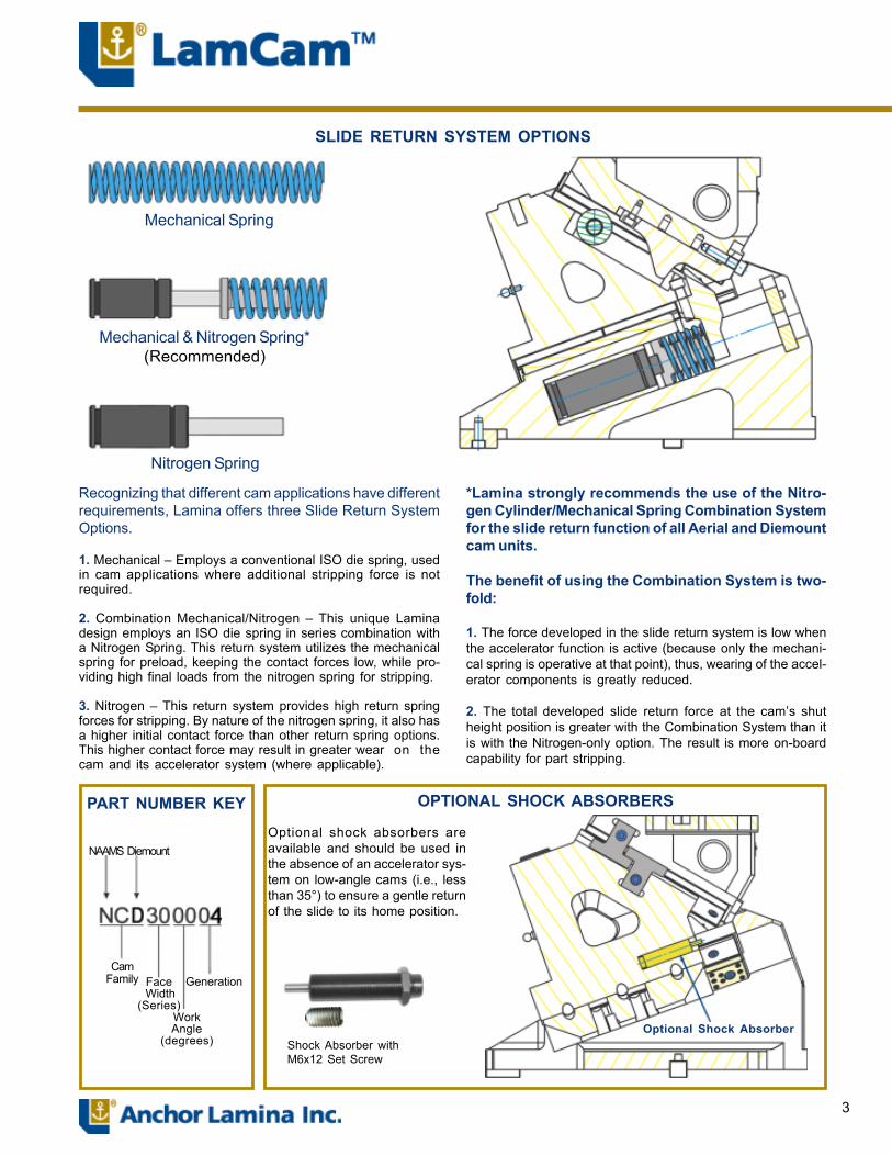
SLIDE RETURN SYSTEM OPTIONS
*Lamina strongly recommends the use of the Nitro-gen Cylinder/Mechanical Spring Combination Systemfor the slide return function of all Aerial and Diemountcam units.
The benefit of using the Combination System is two-fold:
1. The force developed in the slide return system is low whenthe accelerator function is active (because only the mechanicalspring is operative at that point), thus, wearing of the accelera-tor components is greatly reduced.
2. The total developed slide return force at the cam�s shut heightposition is greater with the Combination System than it is withthe Nitrogen-only option. The result is more on-board capabil-ity for part stripping.
OPTIONAL SHOCK ABSORBERSPART NUMBER KEY
Optional shock absorbers areavailable and should be used inthe absence of an accelerator sys-tem on low-angle cams (i.e., lessthan 35°) to ensure a gentle returnof the slide to its home position.
Shock Absorber &M6x12 Set Screw
NAAMS Aerial
CamFamily
Face Width
(Series)WorkAngle
(degrees)
OptionalShock
Absorber
Gener-ation

4
CAM DIAGRAM
ANGLE PRESSSTROKE
WORKSTROKE
0 34.5 28.9 5 34.6 31.910 35.0 35.015 35.7 38.220 36.7 41.525 38.0 45.030 39.8 48.835 42.1 53.140 45.0 57.945 48.8 63.450 53.6 70.055 67.9 78.260 77.9 90.0
X1 ±0.025
X4 (A to B) (+ Dim = B Right)
X5
26
2611
Ø12 (H7)Dowel 2
M12 S.H.C.S. (4)
BASE(Upper)
AERIAL CAMAERIAL CAMAERIAL CAMAERIAL CAMAERIAL CAM50 Series50 Series50 Series50 Series50 Series
52 80
12 (Dowel ±0.013)
X2 (Dowel ±0.013)
X3B
X7 25 Typ 12
Z1
Ø10 (H7)20
±0.25
Angle
X5
60 ±0.25
Ø6 (H7) (2)
20
225 ±0.5
A
X8 (±0.013 Dowels)10 (±0.013 Dowel)
70(±0.013 Dowels)
90DRIVER (0° � 25°)(Bottom View)
M12 S.H.C.S. (3)Ø12 Dowel (H7) (2)
M12 S.H.C.S. (2)X8 (±0.013 Dowels)
10 ±0.013 Dowels)
DRIVER (30° � 60°)(Bottom View)
Ø12 (H7) (2)
70(±0.013 Dowels)
90
X5
* Tooling Ball offset from center.(-Dim = T.B. below center)Note: T.B. (NAAMS M011222)Shown in NAAMS defined locationis for reference only; part and mount-ing provisions not included.
*Z2
100 59
70 ±0.25
90
SLIDE
X6
5
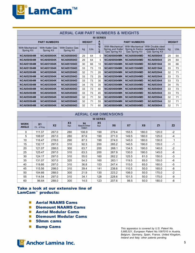
AERIAL CAM PART NUMBERS & WEIGHTS50 SERIES
PART NUMBERS WEIGHT ANGLE
PART NUMBERS WEIGHT
With MechanicalSpring Kit
With Kaller GasSpring Kit
With Dadco GasSpring Kit kg Lbs.
With MechanicalSpring and KallerGas Spring Kit
With MechanicalSpring & DadcoGas Spring Kit
With Double steelwearplates & Dadco
Gas Spring Kitkg Lbs.
NCA050004M NCA050004K NCA050004D 29 64 0 NCA050004MK NCA050004MD NCA050044 29 64NCA050504M NCA050504K NCA050504D 29 64 5 NCA050504MK NCA050504MD NCA050544 29 64NCA051004M NCA051004K NCA051004D 30 66 10 NCA051004MK NCA051004MD NCA051044 30 66NCA051504M NCA051504K NCA051504D 33 73 15 NCA051504MK NCA051504MD NCA051544 33 73NCA052004M NCA052004K NCA052004D 32 71 20 NCA052004MK NCA052004MD NCA052044 32 71NCA052504M NCA052504K NCA052504D 33 73 25 NCA052504MK NCA052504MD NCA052544 33 73NCA053004M NCA053004K NCA053004D 33 73 30 NCA053004MK NCA053004MD NCA053044 33 73NCA053504M NCA053504K NCA053504D 34 75 35 NCA053504MK NCA053504MD NCA053544 34 75NCA054004M NCA054004K NCA054004D 33 73 40 NCA054004MK NCA054004MD NCA054044 33 73NCA054504M NCA054504K NCA054504D 33 73 45 NCA054504MK NCA054504MD NCA054544 33 73NCA055004M NCA055004K NCA055004D 32 71 50 NCA055004MK NCA055004MD NCA055044 32 71NCA055504M NCA055504K NCA055504D 32 71 55 NCA055504MK NCA055504MD NCA055544 32 71NCA056004M NCA056004K NCA056004D 32 71 60 NCA056004MK NCA056004MD NCA056044 32 71
AERIAL CAM DIMENSIONS50 SERIES
WORKANGLE
X1CL of Key
X2X3Ref.
X4Base to Driver
Datum
X5Ref. X6 X7 X8 Z1 Z2
0 111.37 267.0 280 106.9 190 279.4 155.5 180.0 120.0 -2 5 108.97 267.0 280 87.6 190 271.0 149.5 180.0 125.0 -410 116.47 278.0 290 87.3 190 274.0 145.0 180.0 130.0 115 132.17 297.0 310 92.3 200 285.2 140.5 190.0 135.0 -120 121.07 288.0 300 63.7 200 268.1 134.5 190.0 140.0 -225 125.47 297.0 310 63.3 200 267.9 130.0 190.0 145.0 -630 124.17 297.0 310 55.0 160 262.2 125.5 81.0 150.0 -335 131.07 307.0 320 54.3 160 263.1 119.5 85.0 155.0 -640 119.86 297.0 310 36.8 153 247.4 115.0 65.0 160.0 -545 115.56 298.0 310 39.4 141 238.6 110.5 50.0 165.0 -850 104.66 288.0 300 21.9 130 223.2 106.0 50.0 170.0 -255 114.54 297.0 310 34.1 128 228.6 101.5 50.0 175.0 -960 96.64 288.0 300 14.5 123 207.6 98.5 50.0 180.0 -8
Take a look at our extensive line ofLamCam� products:
! Aerial NAAMS Cams! Diemount NAAMS Cams! Aerial Modular Cams! Diemount Modular Cams! 50mm cams! Bump Cams This apparatus is covered by U.S. Patent No.
5,885,521, European Patent No.1097010 in Austria,Belgium, Germany, Spain, France, United Kingdom,Ireland and Italy; other patents pending.

6
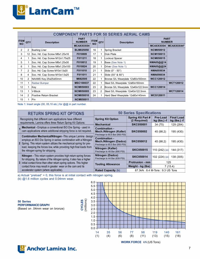
COMPONENT PARTS for 50 Series Aerial Cams
Refer to 50 Series Specification Table for Return Spring Options. See page 3 for more information.
15 19 22 18 8 10
3
24
16
21
3
14
23 13 12 7 20
8
2
6
17
4
11
5
7
6.05.55.04.54.03.53.02.52.01.51.00.50.0
14(1)
35(4)
56(6)
77(8)
98(11)
119(13)
140(15)
161(18)
WORK FORCE kN (US Tons)
CYCL
ES(m
illio
ns)
50 SeriesPERFORMANCE GRAPH(Based on .04mm wear on bronze)
a) Actual �preload� = 0, this force is at initial contact with nitrogen spring.(b) @1.6 million cycles and 0.04mm wear.
50 Series Specifications Spring Kit Option Spring Kit Part #
(2 Required) Pre-Loadkg (lbs.) -f
Final Loadkg (lbs.) -f
Mechanical SKC050001 34 (75) 129 (284) Combination - Mech./Nitrogen (Kaller) Precharge to 65.5 Bar (950 PSI)
SKC050002 45 (98.2) 195 (430)
Combination - Mech./Nitrogen (Dadco) Precharge to 65.5 Bar (950 PSI)
SKC050012 45 (98.2) 195 (430)
Nitrogen (Kaller) Precharge to 48 Bar (690 PSI)
SKC050015 110 (242) (a) 144 (317)
Nitrogen (Dadco) Precharge to 44 Bar (639 PSI)
SKC050014 102 (224) (a) 138 (305)
Tooling Allowance Protrusion - mm 125Weight - kg (lbs) 7 (15.4)
Rated Capacity (b) 87.3kN : 8.4 M-Tons : 9.3 US Tons
RETURN SPRING KIT OPTIONS Recognizing that different cam applications have different requirements, Lamina offers three Return Spring Kit Options:
1 Mechanical - Employs a conventional ISO Die Spring - used in cam applications where additional stripping force is not required.
2
Combination Mechanical/Nitrogen -This unique Lamina design employs an ISO Die Spring in series combination with a Nitrogen Spring. This return system utilizes the mechanical spring for pre- load, keeping the forces low, while providing high final loads from the nitrogen spring for stripping.
3
Nitrogen - This return system provides high return spring forces for stripping. By nature of the nitrogen spring, it also has a higher initial contact force than other return spring options. This higher contact force may result in greater wear on the cam and its accelerator system (where applicable).
COMPONENT PARTS FOR 50 SERIES AERIAL CAMSITEMNO QTY Description
PARTNUMBER ITEM
NO QTY DescriptionPART
NUMBERMCAXXXX04 MCAXXXX04 MCAXXXX44*
2 2 Bushing Liner BLM025050 16 1 Spring Bracket NCM0500123 12 Soc. Hd. Cap Screw M8x1.25x16 F010809 17 1 Disk Plate NCM1500134 1 Soc. Hd. Cap Screw M12x1.75x25 F011211 18 1 Lockout Spacer NCM0500155 1 Soc. Hd. Cap Screw M8x1.25x30 F010812 19 1 Base (See Note 1) NMA05@@146 1 Soc. Hd. Cap Screw M8x1.25x100 F010824 20 1 Driver (See Note 1) NMA05@@247 2 Soc. Hd. Cap Screw M10x1.5x20 F011010 21 1 Slide (0° - 50°) NMA0550348 4 Soc. Hd. Cap Screw M10x1.5x25 F011011 21 1 Slide (55° & 60°) NMA05603410 2 NAAMS Key 25x25x50mm M082505 22 1 Bronze S/L Wearplate 12x80x160mm WCC12001211 1 Rubber Bumper MSC100037 22 1 Steel S/L Wearplate 12x80x160mm WCT12001212 1 Key NCM050003 23 2 Bronze S/L Wearplate 12x40x122.5mm WCC12001413 1 V-Block NCM050005 23 2 Steel S/L Wearplate 12x40x122.5mm WCT12001414 2 Positive Return Bracket NCM050010 24 1 Hard Steel Wearplate 12x80x145mm WCS12001115 1 Pin NCM050011
Note 1: Insert angle (00, 05,10 etc.) for @@ in part number.

8
AERIAL CAM75 Series
22.5
Ø12 (H7) Dowels (2)
Ø12 S.H.C.S. (4)
X2 (Dowel ±0.013)
85 110
13 (Dowel ±0.013)
X3B
X625
12X7
BASE(Upper)
275 ±0.5
X4(A to B)+ Dim = B right)
Angle
AX5X8
X9 ±0.01313 (Dowel ±0.013)
Ø10 (H7)20 ±0.25
70 ±0.25
Ø6 (H7) (2)
Z1
90 ±0.25
115
DRIVER (0° � 20°)(Bottom View)
85 110
Ø12 S/H.C.S. (4)Ø12 (H7) Dowels (2)
X8X9 ±0.013
13
85(±0.013Dowels)
110DRIVER (25° � 60°)(Bottom View)
55110
SLIDE
* Tooling Ball offset from center.(-Dim = T.B. below center)Note: T.B. (NAAMS M011222)Shown in NAAMS defined locationis for reference only; part and mount-ing provisions not included.
*Z2
ANGLE PRESSSTROKE
WORKSTROKE
0 46.0 38.6 5 46.1 42.610 46.7 46.715 47.6 50.920 48.9 55.325 50.7 60.030 53.1 65.135 56.1 70.840 60.0 77.145 65.0 84.550 71.5 93.355 90.6 104.2 60 103.9 120.0
X1 ±0.025
22.5
9
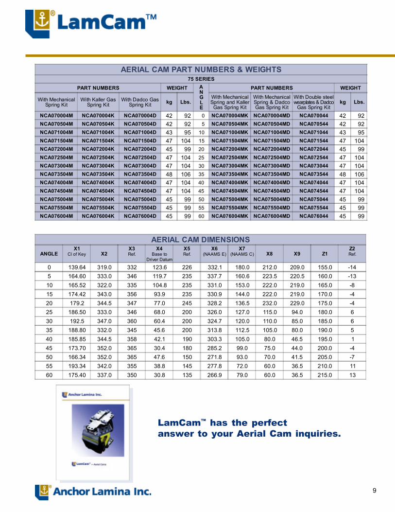
AERIAL CAM DIMENSIONS
ANGLEX1
Cl of Key X2X3Ref.
X4Base to
Driver Datum
X5Ref.
X6(NAAMS E)
X7(NAAMS C) X8 X9 Z1
Z2Ref.
0 139.64 319.0 332 123.6 226 332.1 180.0 212.0 209.0 155.0 -145 164.60 333.0 346 119.7 235 337.7 160.6 223.5 220.5 160.0 -1310 165.52 322.0 335 104.8 235 331.0 153.0 222.0 219.0 165.0 -815 174.42 343.0 356 93.9 235 330.9 144.0 222.0 219.0 170.0 -420 179.2 344.5 347 77.0 245 328.2 136.5 232.0 229.0 175.0 -425 186.50 333.0 346 68.0 200 326.0 127.0 115.0 94.0 180.0 630 192.5 347.0 360 60.4 200 324.7 120.0 110.0 85.0 185.0 635 188.80 332.0 345 45.6 200 313.8 112.5 105.0 80.0 190.0 540 185.85 344.5 358 42.1 190 303.3 105.0 80.0 46.5 195.0 145 173.70 352.0 365 30.4 180 285.2 99.0 75.0 44.0 200.0 -450 166.34 352.0 365 47.6 150 271.8 93.0 70.0 41.5 205.0 -755 193.34 342.0 355 38.8 145 277.8 72.0 60.0 36.5 210.0 1160 175.40 337.0 350 30.8 135 266.9 79.0 60.0 36.5 215.0 13
AERIAL CAM PART NUMBERS & WEIGHTS75 SERIES
PART NUMBERS WEIGHT ANGLE
PART NUMBERS WEIGHT
With MechanicalSpring Kit
With Kaller GasSpring Kit
With Dadco GasSpring Kit kg Lbs.
With MechanicalSpring and KallerGas Spring Kit
With MechanicalSpring & DadcoGas Spring Kit
With Double steelwearplates & Dadco
Gas Spring Kitkg Lbs.
NCA070004M NCA070004K NCA070004D 42 92 0 NCA070004MK NCA070004MD NCA070044 42 92NCA070504M NCA070504K NCA070504D 42 92 5 NCA070504MK NCA070504MD NCA070544 42 92NCA071004M NCA071004K NCA071004D 43 95 10 NCA071004MK NCA071004MD NCA071044 43 95NCA071504M NCA071504K NCA071504D 47 104 15 NCA071504MK NCA071504MD NCA071544 47 104NCA072004M NCA072004K NCA072004D 45 99 20 NCA072004MK NCA072004MD NCA072044 45 99NCA072504M NCA072504K NCA072504D 47 104 25 NCA072504MK NCA072504MD NCA072544 47 104NCA073004M NCA073004K NCA073004D 47 104 30 NCA073004MK NCA073004MD NCA073044 47 104NCA073504M NCA073504K NCA073504D 48 106 35 NCA073504MK NCA073504MD NCA073544 48 106NCA074004M NCA074004K NCA074004D 47 104 40 NCA074004MK NCA074004MD NCA074044 47 104NCA074504M NCA074504K NCA074504D 47 104 45 NCA074504MK NCA074504MD NCA074544 47 104NCA075004M NCA075004K NCA075004D 45 99 50 NCA075004MK NCA075004MD NCA075044 45 99NCA075504M NCA075504K NCA075504D 45 99 55 NCA075504MK NCA075504MD NCA075544 45 99NCA076004M NCA076004K NCA076004D 45 99 60 NCA076004MK NCA076004MD NCA076044 45 99
LamCam� has the perfectanswer to your Aerial Cam inquiries.
10
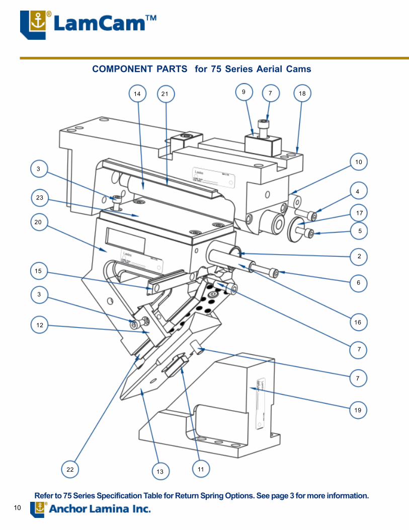
COMPONENT PARTS for 75 Series Aerial Cams
Refer to 75 Series Specification Table for Return Spring Options. See page 3 for more information.
14 21 9 7 18
10
4
17
5
2
6
16
7
7
19
111322
12
3
15
20
3
23
11
6.05.55.04.54.03.53.02.52.01.51.00.50.0
12(1)
47(5)
82(9)
107(12)
140(15)
175(19)
210(23)
245(27)
280(31)
WORK FORCE kN (US Tons)
CYCL
ES(m
illio
ns)
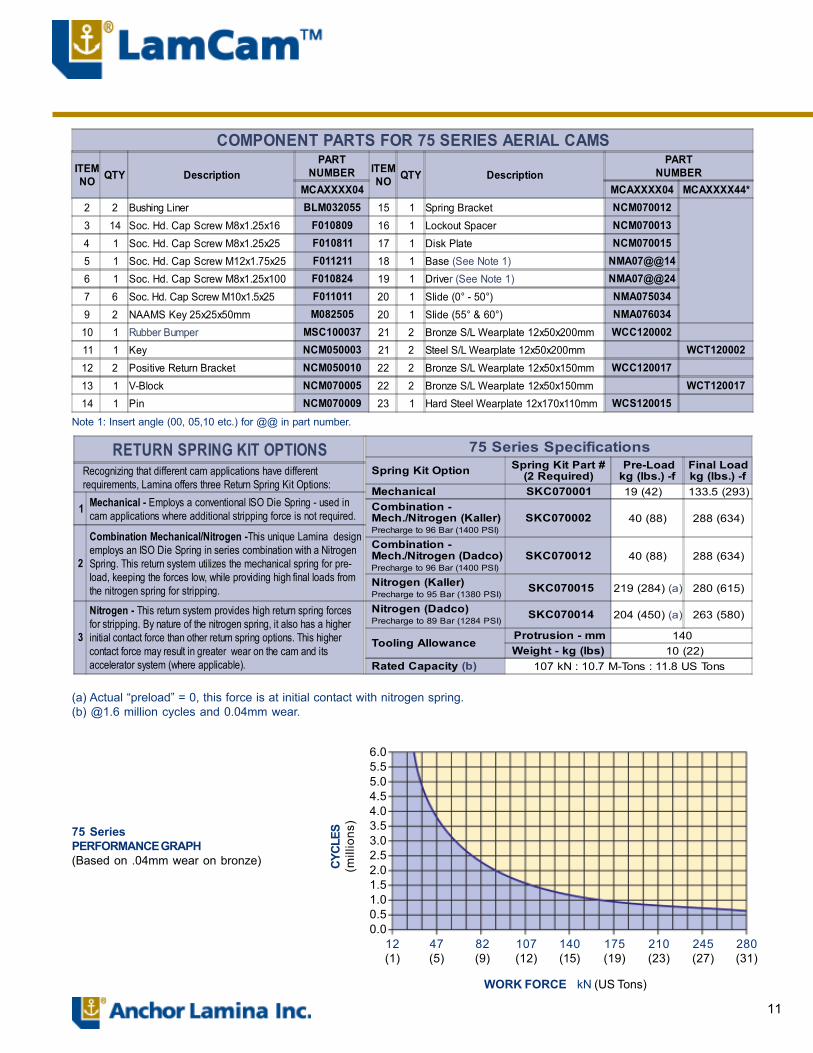
75 SeriesPERFORMANCE GRAPH(Based on .04mm wear on bronze)
(a) Actual �preload� = 0, this force is at initial contact with nitrogen spring.(b) @1.6 million cycles and 0.04mm wear.
75 Series Specifications Spring Kit Option Spring Kit Part #
(2 Required) Pre-Loadkg (lbs.) -f
Final Loadkg (lbs.) -f
Mechanical SKC070001 19 (42) 133.5 (293) Combination - Mech./Nitrogen (Kaller) Precharge to 96 Bar (1400 PSI)
SKC070002 40 (88) 288 (634)
Combination - Mech./Nitrogen (Dadco) Precharge to 96 Bar (1400 PSI)
SKC070012 40 (88) 288 (634)
Nitrogen (Kaller) Precharge to 95 Bar (1380 PSI)
SKC070015 219 (284) (a) 280 (615)
Nitrogen (Dadco) Precharge to 89 Bar (1284 PSI)
SKC070014 204 (450) (a) 263 (580)
Tooling Allowance Protrusion - mm 140Weight - kg (lbs) 10 (22)
Rated Capacity (b) 107 kN : 10.7 M-Tons : 11.8 US Tons
RETURN SPRING KIT OPTIONS Recognizing that different cam applications have different requirements, Lamina offers three Return Spring Kit Options:
1 Mechanical - Employs a conventional ISO Die Spring - used in cam applications where additional stripping force is not required.
2
Combination Mechanical/Nitrogen -This unique Lamina design employs an ISO Die Spring in series combination with a Nitrogen Spring. This return system utilizes the mechanical spring for pre- load, keeping the forces low, while providing high final loads from the nitrogen spring for stripping.
3
Nitrogen - This return system provides high return spring forces for stripping. By nature of the nitrogen spring, it also has a higher initial contact force than other return spring options. This higher contact force may result in greater wear on the cam and its accelerator system (where applicable).
COMPONENT PARTS FOR 75 SERIES AERIAL CAMSITEMNO QTY Description
PARTNUMBER ITEM
NO QTY DescriptionPART
NUMBERMCAXXXX04 MCAXXXX04 MCAXXXX44*
2 2 Bushing Liner BLM032055 15 1 Spring Bracket NCM0700123 14 Soc. Hd. Cap Screw M8x1.25x16 F010809 16 1 Lockout Spacer NCM0700134 1 Soc. Hd. Cap Screw M8x1.25x25 F010811 17 1 Disk Plate NCM0700155 1 Soc. Hd. Cap Screw M12x1.75x25 F011211 18 1 Base (See Note 1) NMA07@@146 1 Soc. Hd. Cap Screw M8x1.25x100 F010824 19 1 Driver (See Note 1) NMA07@@247 6 Soc. Hd. Cap Screw M10x1.5x25 F011011 20 1 Slide (0° - 50°) NMA0750349 2 NAAMS Key 25x25x50mm M082505 20 1 Slide (55° & 60°) NMA07603410 1 Rubber Bumper MSC100037 21 2 Bronze S/L Wearplate 12x50x200mm WCC12000211 1 Key NCM050003 21 2 Steel S/L Wearplate 12x50x200mm WCT12000212 2 Positive Return Bracket NCM050010 22 2 Bronze S/L Wearplate 12x50x150mm WCC12001713 1 V-Block NCM070005 22 2 Bronze S/L Wearplate 12x50x150mm WCT12001714 1 Pin NCM070009 23 1 Hard Steel Wearplate 12x170x110mm WCS120015
Note 1: Insert angle (00, 05,10 etc.) for @@ in part number.
12
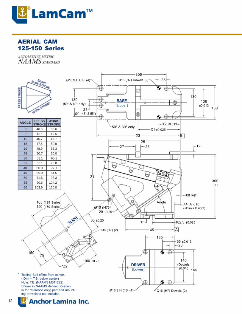
AERIAL CAM125-150 Series
305Ø16 S.H.C.S. (4) Ø16 (H7) Dowels (2) 35
130136
±0.013160
130(50° & 60° only)
28(0° � 45° & 55°)
BASE(Upper)
50° & 60° onlyX2 ±0.013
X1 ±0.025
X3 B
X6X7 25 12
Z1300±0.5
X8 Ref
X4 (A to B)(+Dim = B right)
AngleØ10 (H7)
20 ±0.25
80 ±0.25
Ø6 (H7) (2)
13 102.5 ±0.025
X5 A
13555 ±0.01320
100 ±0.25DRIVER(Lower)
140(Dowels±0.013 165
Ø16 S.H.C.S. (4) Ø16 (H7) Dowels (2)
*Z2
165 (125 Series)190 (150 Series)
15075
SLIDE
* Tooling Ball offset from center.(-Dim = T.B. below center)Note: T.B. (NAAMS M011222)Shown in NAAMS defined locationis for reference only; part and mount-ing provisions not included.
ELGNA SSERPEKORTS
KROWEKORTS
0 0.64 6.83
5 1.64 6.24
01 7.64 7.64
51 6.74 9.05
02 9.84 3.55
52 7.05 0.06
03 1.35 1.56
53 1.65 8.07
04 0.06 1.77
54 0.56 5.48
05 5.17 3.39
55 6.09 2.401
06 9.301 0.021
13
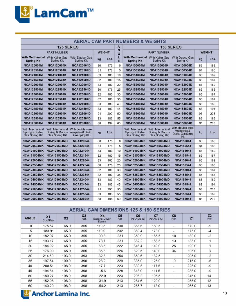
AERIAL CAM PART NUMBERS & WEIGHTS125 SERIES A
NGLE
150 SERIESPART NUMBER WEIGHT PART NUMBER WEIGHT
With MechanicalSpring Kit
With Kaller GasSpring Kit
With Dadco GasSpring Kit kg Lbs. With Mechanical
Spring KitWith Kaller Gas
Spring KitWith Dadco Gas
Spring Kit kg Lbs.
NCA120004M NCA120004K NCA120004D 80 175 0 NCA150004M NCA150004K NCA150004D 83 183NCA120504M NCA120504K NCA120504D 81 178 5 NCA150504M NCA150504K NCA150504D 84 185NCA121004M NCA121004K NCA121004D 83 183 10 NCA151004M NCA151004K NCA151004D 86 189NCA121504M NCA121504K NCA121504D 82 180 15 NCA151504M NCA151504K NCA151504D 85 187NCA122004M NCA122004K NCA122004D 83 183 20 NCA152004M NCA152004K NCA152004D 86 189NCA122504M NCA122504K NCA122504D 80 176 25 NCA152504M NCA152504K NCA152504D 83 183NCA123004M NCA123004K NCA123004D 82 180 30 NCA153004M NCA153004K NCA153004D 85 187NCA123504M NCA123504K NCA123504D 82 180 35 NCA153504M NCA153504K NCA153504D 85 187NCA124004M NCA124004K NCA124004D 83 183 40 NCA154004M NCA154004K NCA154004D 86 189NCA124504M NCA124504K NCA124504D 83 183 45 NCA154504M NCA154504K NCA154504D 88 194NCA125004M NCA125004K NCA125004D 91 200 50 NCA155004M NCA155004K NCA155004D 93 205NCA125504M NCA125504K NCA125504D 83 183 55 NCA155504M NCA155504K NCA155504D 86 189NCA126004M NCA126004K NCA126004D 88 194 60 NCA156004M NCA156004K NCA156004D 91 200
With MechanicalSpring & KallerGas Spring Kit
With MechanicalSpring & DadcoGas Spring Kit
With double steelwearplates & Dadco
Gas Spring Kitkg Lbs.
With MechanicalSpring & KallerGas Spring Kit
With MechanicalSpring & DadcoGas Spring Kit
With double steelwearplates &
Dadco Gas SpringKit
kg Lbs.
NCA120004MK NCA120004MD NCA120044 80 175 0 NCA150004MK NCA150004MD NCA150044 83 183NCA120504MK NCA120504MD NCA120544 81 178 5 NCA150504MK NCA150504MD NCA150544 84 185NCA121004MK NCA121004MD NCA121044 83 183 10 NCA151004MK NCA151004MD NCA151044 86 189NCA121504MK NCA121504MD NCA121544 82 180 15 NCA151504MK NCA151504MD NCA151544 85 187NCA122004MK NCA122004MD NCA122044 83 183 20 NCA152004MK NCA152004MD NCA152044 86 189NCA122504MK NCA122504MD NCA122544 80 176 25 NCA152504MK NCA152504MD NCA152544 83 183NCA123004MK NCA123004MD NCA123044 82 180 30 NCA153004MK NCA153004MD NCA153044 85 187NCA123504MK NCA123504MD NCA123544 82 180 35 NCA153504MK NCA153504MD NCA153544 85 187NCA124004MK NCA124004MD NCA124044 83 183 40 NCA154004MK NCA154004MD NCA154044 86 189NCA124504MK NCA124504MD NCA124544 83 183 45 NCA154504MK NCA154504MD NCA154544 88 194NCA125004MK NCA125004MD NCA125044 91 200 50 NCA155004MK NCA155004MD NCA155044 93 205NCA125504MK NCA125504MD NCA125544 83 183 55 NCA155504MK NCA155504MD NCA155544 86 189NCA126004MK NCA126004MD NCA126044 88 194 60 NCA156004MK NCA156004MD NCA156044 91 200
AERIAL CAM DIMENSIONS 125 & 150 SERIESANGLE X1
CL of Key X2X3Ref.
X4Base to Driver
Datum
X5Ref.
X6(NAAMS E)
X7(NAAMS C)
X8Ref. Z1
Z2Ref.
0 175.57 65.0 355 119.5 230 368.6 180.5 - 170.0 -9 5 183.91 65.0 355 110.0 232 369.4 173.0 - 175.0 -410 182.97 65.0 355 90.8 231 359.9 165.5 10 180.0 -215 193.17 65.0 355 78.7 231 362.2 156.5 13 185.0 120 184.92 65.0 355 63.5 222 346.4 149.0 25 190.0 125 176.99 65.0 355 35.3 226 329.5 140.0 34 195.0 330 214.60 103.0 393 32.3 254 359.6 132.5 - 205.0 -235 197.54 100.0 390 28.2 229 335.0 125.0 9 215.0 -640 200.51 108.0 398 17.7 223 330.5 117.5 - 225.0 -945 194.84 108.0 398 -5.6 228 318.9 111.5 - 235.0 -950 180.27 108.0 398 -22.0 223 298.2 105.5 - 245.0 -14 55 152.08 108.0 398 -31.9 213 284.6 120.0 - 255.0 -12 60 140.20 108.0 398 -54.2 213 265.7 113.0 - 265.0 -13

14
COMPONENT PARTS for 125�150 Series Aerial Cams
Refer to 125/150 Series Specification Table for ReturnSpring Options. See page 3 for more information.
7 30 28 11 18 32 20
19
25
3
5
10
21
33
12
27
14
1
7
29
3748229
31
26
23
8
30
17
15
24
13
35
36
6
7
34
SHOCK ABSORBERS � OPTIONALQty PART
NUMBER DESCRIPTION
2 MSC100028 Shock Absorber AssembliesShock absorber locations noted in red on drawing
15
6.05.55.04.54.03.53.02.52.01.51.00.50.0
14(1)
56(6)
98(11)
140(15)
177(19)
210(23)
252(28)
294(32)
336(37)
WORK FORCE kN (US Tons)
CYCL
ES(m
illio
ns)
125/150 SeriesPERFORMANCE GRAPH(Based on .04mm wear on bronze)
a) Actual �preload� = 0, this force is at initial contact with nitrogen spring.(b) @1.6 million cycles and 0.04mm wear.
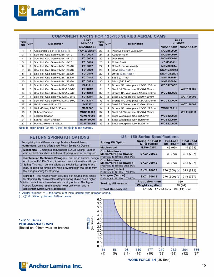
Note 1: Insert angle (00, 05,10 etc.) for @@ in part number.
125 - 150 Series SpecificationsSpring Kit Option Spring Kit Part #
(2 Required) Pre-Loadkg (lbs.) -f
Final Loadkg (lbs.) -f
Mechanical ILD040254 45 (99) 149 (328)Combination -Mech./Nitrogen (Kaller)PreCharge to 150 Bar (2175 PSI)
SKC120002 33 (73) 361 (797)
Combination -Mech./Nitrogen (Dadco)PreCharge to 150 Bar (2175 PSI)
SKC120012 33 (73) 361 (797)
Nitrogen (Kaller)PreCharge to 121 Bar (1750 PSI)
SKC120003 276 (609) (a) 373 (822)
Nitrogen (Dadco)PreCharge to 121 Bar (1750 PSI)
SKC120013 276 (609) (a) 348 (767)
Tooling Allowance Protrusion - mm 150Weight - kg (lbs) 20 (44)
Rated Capacity (b) 176 kN : 17.7 M-Tons : 19.5 US Tons
RETURN SPRING KIT OPTIONS Recognizing that different cam applications have different requirements, Lamina offers three Return Spring Kit Options:
1 Mechanical - Employs a conventional ISO Die Spring - used in cam applications where additional stripping force is not required.
2
Combination Mechanical/Nitrogen -This unique Lamina design employs an ISO Die Spring in series combination with a Nitrogen Spring. This return system utilizes the mechanical spring for pre- load, keeping the forces low, while providing high final loads from the nitrogen spring for stripping.
3
Nitrogen - This return system provides high return spring forces for stripping. By nature of the nitrogen spring, it also has a higher initial contact force than other return spring options. This higher contact force may result in greater wear on the cam and its accelerator system (where applicable).
COMPONENT PARTS FOR 125-150 SERIES AERIAL CAMSITEMNO QTY Description
PARTNUMBER ITEM
NO QTY DescriptionPART
NUMBERNCAXXXX04 NCAXXXX04 NCAXXXX44*
1 1 Accelerator Block (See Note 1) 14A1230@@R 23 2 Positive Return Guideway NCM1500093 1 Soc. Hd. Cap Screw M6x1.0x12 F010608 24 2 Keeper Plate NCM1500104 2 Soc. Hd. Cap Screw M6x1.0x16 F010609 25 1 Disk Plate NCM1500145 2 Soc. Hd. Cap Screw M6x1.0x20 F010610 26 1 Roller Shaft NCM3000116 3 Soc. Hd. Cap Screw M8x1.25x10 F010807 27 1 Roller/Liner Assembly NCM300014
7 35 Soc. Hd. Cap Screw M8x1.25x16 F010809 28 1 Base (See Note 1) NMA12@@138 3 Soc. Hd. Cap Screw M8x1.25x20 F010810 29 1 Driver (See Note 1) NMA12@@249 4 Soc. Hd. Cap Screw M8x1.25x40 F010814 30 1 Slide (0° � 50°) NMA15503410 2 Soc. Hd. Cap Screw M8x1.25x90 F010823 30 1 Slide (55° & 60°) NMA15603411 3 Soc. Hd. Cap Screw M10x1.5x25 F011011 31 2 Bronze S/L Wearplate 12x50x200mm WCC12000212 2 Soc. Hd. Cap Screw M12x1.50x30 F011012 31 2 Steel S/L Wearplate 12x50x200mm WCT12000213 6 Soc. Hd. Cap Screw M12x1.75x35 F011213 32 2 Bronze S/L Wearplate 12x30x160mm WCC12000614 1 Soc. Hd. Cap Screw M12x1.75x45 F011215 32 2 Steel S/L Wearplate 12x30x160mm WCT12000615 4 Soc. Hd. Cap Screw M12x1.75x90 F011223 33 6 Bronze S/L Wearplate 12x30x125mm WCC12000917 4 Hex Locknut M12x1.75 M1217 33 6 Steel S/L Wearplate 12x30x125mm WCT12000918 3 NAAMS Key 25x25x50mm M082505 34 1 Bronze S/L Wearplate 12x50x225mm WCC12001119 1 Rubber Bumper MSC100003 34 1 Steel S/L Wearplate 12x50x225mm WCT12001120 2 Lockout Spacer NCM070008 35 2 Steel Wearplate 12x30x285mm WCS12000821 1 Spring Return Bracket NCM150001 36 1 Steel Wearplate 12x48x280mm WCS12001022 2 Positive Return Bracket NCM150008 37 2 Steel Wearplate 12x48x225mm WCS120005
16
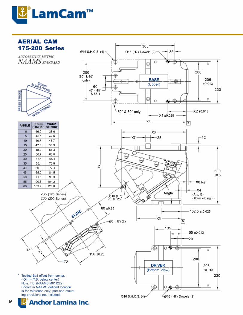
AERIAL CAM175-200 Series 305
35Ø16 (H7) Dowels (2)Ø16 S.H.C.S. (4)
200(50° & 60°
only) BASE(Upper)
200
206±0.013
60(0° - 45°& 55°)
50° & 60° only
230
X2 ±0.013X1 ±0.025
X3 B
X6X7 25 12
Z1300±0.5
X8 Ref
Angle X4(A to B)(+Dim = B right)
Ø10 (H7)20 ±0.25
80 ±0.25
Ø6 (H7) (2)X5
102.5 ± 0.025
A
13555 ±0.013
20
200
206±0.013
230
Ø16 S.H.C.S. (4) Ø16 (H7) Dowels (2)
DRIVER(Bottom View)
156 ±0.25
*Z2
75150
235 (175 Series)260 (200 Series)
SLIDE
* Tooling Ball offset from center.(-Dim = T.B. below center)Note: T.B. (NAAMS M011222)Shown in NAAMS defined locationis for reference only; part and mount-ing provisions not included.
ANGLE PRESSSTROKE
WORKSTROKE
0 46.0 38.6 5 46.1 42.610 46.7 46.715 47.6 50.920 48.9 55.325 50.7 60.030 53.1 65.135 56.1 70.840 60.0 77.145 65.0 84.550 71.5 93.355 90.6 104.2 60 103.9 120.0

17
AERIAL CAM PART NUMBERS & WEIGHTS175 SERIES A
NGLE
200 SERIESPART NUMBER WEIGHT PART NUMBER WEIGHT
With MechanicalSpring Kit
With Kaller GasSpring Kit
With Dadco GasSpring Kit kg Lbs. With Mechanical
Spring KitWith Kaller Gas
Spring KitWith Dadco Gas
Spring Kit kg Lbs.
NCA170004M NCA170004K NCA170004D 193 425 0 NCA200004M NCA200004K NCA200004D 197 433NCA170504M NCA170504K NCA170504D 187 411 5 NCA200504M NCA200504K NCA200504D 191 420NCA171004M NCA171004K NCA171004D 190 418 10 NCA201004M NCA201004K NCA201004D 194 427NCA171504M NCA171504K NCA171504D 189 416 15 NCA201504M NCA201504K NCA201504D 193 425NCA172004M NCA172004K NCA172004D 189 416 20 NCA202004M NCA202004K NCA202004D 193 425NCA172504M NCA172504K NCA172504D 188 414 25 NCA202504M NCA202504K NCA202504D 192 422NCA173004M NCA173004K NCA173004D 188 414 30 NCA203004M NCA203004K NCA203004D 192 422NCA173504M NCA173504K NCA173504D 187 411 35 NCA203504M NCA203504K NCA203504D 191 420NCA174004M NCA174004K NCA174004D 188 414 40 NCA204004M NCA204004K NCA204004D 192 422NCA174504M NCA174504K NCA174504D 191 420 45 NCA204504M NCA204504K NCA204504D 195 429NCA175004M NCA175004K NCA175004D 208 458 50 NCA205004M NCA205004K NCA205004D 212 466NCA175504M NCA175504K NCA175504D 211 464 55 NCA205504M NCA205504K NCA205504D 215 473NCA176004M NCA176004K NCA176004D 213 469 60 NCA206004M NCA206004K NCA206004D 217 477
With MechanicalSpring & KallerGas Spring Kit
With MechanicalSpring & DadcoGas Spring Kit
With double steelwearplates & Dadco
Gas Spring Kitkg Lbs.
With MechanicalSpring & KallerGas Spring Kit
With MechanicalSpring & DadcoGas Spring Kit
With double steelwearplates & Dadco
Gas Spring Kitkg Lbs.
NCA170004MK NCA170004MD NCA170044 193 425 0 NCA200004MK NCA200004MD NCA200044 197 433NCA170504MK NCA170504MD NCA170544 187 411 5 NCA200504MK NCA200504MD NCA200544 191 420NCA171004MK NCA171004MD NCA171044 190 418 10 NCA201004MK NCA201004MD NCA201044 194 427NCA171504MK NCA171504MD NCA171544 189 416 15 NCA201504MK NCA201504MD NCA201544 193 425NCA172004MK NCA172004MD NCA172044 189 416 20 NCA202004MK NCA202004MD NCA202044 193 425NCA172504MK NCA172504MD NCA172544 188 414 25 NCA202504MK NCA202504MD NCA202544 192 422NCA173004MK NCA173004MD NCA173044 188 414 30 NCA203004MK NCA203004MD NCA203044 192 422NCA173504MK NCA173504MD NCA173544 187 411 35 NCA203504MK NCA203504MD NCA203544 191 420NCA174004MK NCA174004MD NCA174044 188 414 40 NCA204004MK NCA204004MD NCA204044 192 422NCA174504MK NCA174504MD NCA174544 191 420 45 NCA204504MK NCA204504MD NCA204544 195 429NCA175004MK NCA175004MD NCA175044 208 458 50 NCA205004MK NCA205004MD NCA205044 212 466NCA175504MK NCA175504MD NCA175544 211 464 55 NCA205504MK NCA205504MD NCA205544 215 473NCA176004MK NCA176004MD NCA176044 213 469 60 NCA206004MK NCA206004MD NCA206044 217 477
AERIAL CAM DIMENSIONS 175 & 200 SERIES
ANGLE X1Cl of Key
X2X3Ref.
X4Base to
Driver Datum
X5Ref.
X6(NAAMS E)
X7(NAAMS C)
X8Ref. Z1
Z2Ref.
0 175.54 65.0 355 119.5 230 368.6 180.5 - 170.0 -9 5 183.90 65.0 355 110.1 232 369.4 173.0 - 175.0 -410 177.20 65.0 355 86.9 231 355.2 165.5 17.2 180.0 -115 193.20 65.0 355 84.7 231 362.2 156.5 11.0 185.0 120 184.90 65.0 355 63.7 222 346.4 149.0 25.0 190.0 125 177.00 65.0 355 34.2 226 329.5 140.0 36.0 195.0 330 214.65 103.0 393 35.4 254 359.6 132.5 - 205.0 -235 202.50 100.0 390 32.4 229 340.0 125.0 4.0 215.0 -640 202.50 110.0 400 22.1 223 332.5 117.5 - 225.0 -945 191.90 115.0 405 -6.4 228 315.9 111.5 - 235.0 -950 180.27 108.0 398 -20.0 223 298.2 105.5 - 245.0 -1455 148.89 115.0 405 -33.3 213 281.6 120.0 - 255.0 -1260 140.20 108.0 398 -51.9 213 265.7 113.0 - 265.0 -13

18
COMPONENT PARTS for 175�200 Series Aerial Cams
Refer to 175/200 Series Specification Table for ReturnSpring Options. See page 3 for more information.
SHOCK ABSORBERS � OPTIONALQty PART
NUMBER DESCRIPTION
2 MSC100028 Shock Absorber AssembliesShock absorber locations noted in red on drawing
35 6 30 17 10 30 27
19
9
18
24
3
5
23
11
13
28613672084
31
25
26
21
22
14
16
29
7
12
33
6
32
34

19
6.05.55.04.54.03.53.02.52.01.51.00.50.0
175/200 SeriesPERFORMANCE GRAPH(Based on .04mm wear on bronze)
WORK FORCE kN (US Tons)
CYCL
ES(m
illio
ns)
(a) Actual �preload� = 0, this force is at initial contact with nitrogen spring.(b) @1.6 million cycles and 0.04mm wear.
Note 1: Insert angle (00, 05,10 etc.) for @@ in part number.
22(2)
90(10)
157(17)
224(25)
269(30)
336(37)
403(45)
470(52)
537(60)
RETURN SPRING KIT OPTIONS Recognizing that different cam applications have different requirements, Lamina offers three Return Spring Kit Options:
1 Mechanical - Employs a conventional ISO Die Spring - used in cam applications where additional stripping force is not required.
2
Combination Mechanical/Nitrogen -This unique Lamina design employs an ISO Die Spring in series combination with a Nitrogen Spring. This return system utilizes the mechanical spring for pre- load, keeping the forces low, while providing high final loads from the nitrogen spring for stripping.
3
Nitrogen - This return system provides high return spring forces for stripping. By nature of the nitrogen spring, it also has a higher initial contact force than other return spring options. This higher contact force may result in greater wear on the cam and its accelerator system (where applicable).
175 - 200 Series SpecificationsSpring Kit Option Spring Kit Part # Pre-Load
kg (lbs.) -fFinal Loadkg (lbs.) -f
Mechanical SKC170001 64 (141) 278 (613)Combination -Mech./Nitrogen (Kaller)PreCharge to 110 Bar (1595 PSI)
SKC170002 51.3 (113) 458 (1010)
Combination -Mech./Nitrogen (Dadco)PreCharge to 110 Bar (1595 PSI)
SKC170012 51.3 (113) 458 (1010)
Nitrogen (Kaller)PreCharge to 86 Bar (1250 PSI)
SKC170003 276 (609) (a) 373 (822)
Nitrogen (Dadco)PreCharge to 69 Bar (1250 PSI)
SKC170013 276 (609) (a) 348 (767)
Tooling Allowance Protrusion - mm 175Weight - kg (lbs) 32 (70)
Rated Capacity (b) 241.8 kN : 24.2 M-Tons : 26.6 US Tons
COMPONENT PARTS FOR 175-200 SERIES AERIAL CAMSITEMNO QTY Description
PARTNUMBER ITEM
NO QTY DescriptionPART
NUMBERMCAXXXX04 MCAXXXX04 MCAXXXX44*
1 1 Accelerator Block (See Note 1) 14A1230@@R 23 1 Spring Return Bracket NCM2000013 1 Soc. Hd. Cap Screw M6x1.0x12 F010608 24 1 Disk Plate NCM2000084 2 Soc. Hd. Cap Screw M6x1.0x16 F010609 25 1 Roller Shaft NCM3000115 2 Soc. Hd. Cap Screw M6x1.0x20 F010610 26 1 Roller/Liner Assembly NCM300014
6 50 Soc. Hd. Cap Screw M8x1.25x16 F010809 27 1 Base (See Note 1) NMA17@@137 3 Soc. Hd. Cap Screw M8x1.25x20 F010810 28 1 Driver (See Note 1) NMA17@@248 4 Soc. Hd. Cap Screw M8x1.25x40 F010814 29 1 Slide (0° � 50°) NMA2050349 2 Soc. Hd. Cap Screw M8x1.25x90 F010823 29 1 Slide (55° & 60°) NMA20603410 3 Soc. Hd. Cap Screw M10x1.5x25 F011011 30 2 Bronze S/L Wearplate 12x30x160mm WCC12000611 2 Soc. Hd. Cap Screw M10x1.5x30 F011012 30 2 Steel S/L Wearplate 12x30x160mm WCT12000612 6 Soc. Hd. Cap Screw M12x1.75x35 F011213 31 4 Bronze S/L Wearplate 12x38x200mm WCC12000713 1 Soc. Hd. Cap Screw M12x1.75x45 F011215 31 4 Steel S/L Wearplate 12x38x200mm WCT12000714 4 Soc. Hd. Cap Screw M12x1.75x90 F011223 32 1 Bronze S/L Wearplate 12x100x240mm WCC12000816 4 Hex Locknut M12x1.75 M1217 32 1 Steel S/L Wearplate 12x100x240mm WCT12000817 3 NAAMS Key 25x25x50mm M082505 33 6 Bronze S/L Wearplate 12x30x125mm WCC12000918 1 Rubber Bumper MSC100003 33 6 Steel S/L Wearplate 12x30x125mm WCT12000919 2 Lockout Spacer NCM070008 34 1 Steel Wearplate 12x100x290mm WCS12000620 2 Positive Return Bracket NCM150008 35 2 Steel Wearplate 12x30x285mm WCS12000821 2 Positive Return Guideway NCM150009 36 4 Hard Steel Wearplate 12x38x225mm WCS12000922 2 Keeper Plate NCM150010

20
AERIAL CAM250-300 Series
Ø020 S.H.C.S. (4)
X9
Ø20 (H7)Dowels (2)
40
90 BASE(Upper)
285
290±0.013
330
X2 ±0.013
X1 ±0.025
X3 B
X612X7 25
Z1
X8 Ref375±0.5
X4 (A to B)(+Dim = B right)
AngleØ10 (H7)20±0.25
110 ±0.25
112.5
X5 A
Ø6 (H7) (2)145
55 ±0.013
20
280290
±0.013320
DRIVER(Bottom View)
Ø20 S.H.C.S. (4) Ø20 (H7) Dowels (2)
330 (250 Series)400 (300 Series)
180 90 230 ±0.25
*Z2
SLIDE
* Tooling Ball offset from center.(-Dim = T.B. below center)Note: T.B. (NAAMS M011222)Shown in NAAMS defined location is forreference only; part and mounting provisions not included.
ANGLE PRESSSTROKE
WORKSTROKE
0 46.0 38.6 5 46.1 42.610 46.7 46.715 47.6 50.920 48.9 55.325 50.7 60.030 53.1 65.135 56.1 70.840 60.0 77.145 65.0 84.550 71.5 93.355 90.6 104.2 60 103.9 120.0
21
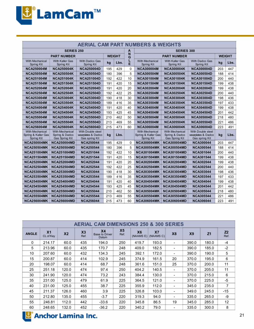
AERIAL CAM PART NUMBERS & WEIGHTS SERIES 250 A
NGLE
SERIES 300PART NUMBER WEIGHT PART NUMBER WEIGHT
With MechanicalSpring Kit
With Kaller GasSpring Kit
With Dadco GasSpring Kit kg Lbs. With Mechanical
Spring KitWith Kaller Gas
Spring KitWith Dadco Gas
Spring Kit kg Lbs.
NCA250004M NCA250004K NCA250004D 195 429 0 NCA300004M NCA300004K NCA300004D 203 447NCA250504M NCA250504K NCA250504D 180 396 5 NCA300504M NCA300504K NCA300504D 188 414NCA251004M NCA251004K NCA251004D 192 422 10 NCA301004M NCA301004K NCA301004D 200 440NCA251504M NCA251504K NCA251504D 191 420 15 NCA301504M NCA301504K NCA301504D 199 438NCA252004M NCA252004K NCA252004D 191 420 20 NCA302004M NCA302004K NCA302004D 199 438NCA252504M NCA252504K NCA252504D 192 422 25 NCA302504M NCA302504K NCA302504D 200 440NCA253004M NCA253004K NCA253004D 190 418 30 NCA303004M NCA303004K NCA303004D 198 436NCA253504M NCA253504K NCA253504D 189 416 35 NCA303504M NCA303504K NCA303504D 197 433NCA254004M NCA254004K NCA254004D 191 420 40 NCA304004M NCA304004K NCA304004D 199 438NCA254504M NCA254504K NCA254504D 193 425 45 NCA304504M NCA304504K NCA304504D 201 442NCA255004M NCA255004K NCA255004D 210 462 50 NCA305004M NCA305004K NCA305004D 218 480NCA255504M NCA255504K NCA255504D 213 469 55 NCA305504M NCA305504K NCA305504D 221 486NCA256004M NCA256004K NCA256004D 215 473 60 NCA306004M NCA306004K NCA306004D 223 491With Mechanical
Spring & Kaller GasSpring Kit
With MechanicalSpring & DadcoGas Spring Kit
With Double steelwearplates & Dadco
Gas spring Kitkg Lbs.
With MechanicalSpring & Kaller Gas
Spring Kit
With MechanicalSpring & DadcoGas Spring Kit
With Double steelwearplates & Dadco
Gas spring Kitkg Lbs.
NCA250004MK NCA250004MD NCA250044 195 429 0 NCA300004MK NCA300004MD NCA300044 203 447NCA250504MK NCA250504MD NCA250544 180 396 5 NCA300504MK NCA300504MD NCA300544 188 414NCA251004MK NCA251004MD NCA251044 192 422 10 NCA301004MK NCA301004MD NCA301044 200 440NCA251504MK NCA251504MD NCA251544 191 420 15 NCA301504MK NCA301504MD NCA301544 199 438NCA252004MK NCA252004MD NCA252044 191 420 20 NCA302004MK NCA302004MD NCA302044 199 438NCA252504MK NCA252504MD NCA252544 192 422 25 NCA302504MK NCA302504MD NCA302544 200 440NCA253004MK NCA253004MD NCA253044 190 418 30 NCA303004MK NCA303004MD NCA303044 198 436NCA253504MK NCA253504MD NCA253544 189 416 35 NCA303504MK NCA303504MD NCA303544 197 433NCA254004MK NCA254004MD NCA254044 191 420 40 NCA304004MK NCA304004MD NCA304044 199 438NCA254504MK NCA254504MD NCA254544 193 425 45 NCA304504MK NCA304504MD NCA304544 201 442NCA255004MK NCA255004MD NCA255044 210 462 50 NCA305004MK NCA305004MD NCA305044 218 480NCA255504MK NCA255504MD NCA255544 213 469 55 NCA305504MK NCA305504MD NCA305544 221 486NCA256004MK NCA256004MD NCA256044 215 473 60 NCA306004MK NCA306004MD NCA306044 223 491
AERIAL CAM DIMENSIONS 250 & 300 SERIES
ANGLE X1CL of Key
X2 X3Ref.
X4Base to Driver
Datum
X5Ref. X6
(NAAMS E)X7
(NAAMS C)X8 X9 Z1 Z2
Ref.
0 214.17 60.0 435 194.0 250 419.7 193.0 - 390.0 180.0 -4 5 213.96 60.0 435 170.7 248 409.0 182.5 - 390.0 185.0 -210 207.60 60.0 432 134.3 245 392.1 172.0 - 390.0 190.0 515 200.87 60.0 414 102.9 245 374.9 161.5 20 370.0 195.0 620 198.07 60.0 414 68.7 248 361.6 151.0 25 370.0 200.0 11 25 251.18 120.0 474 97.4 250 404.2 140.5 - 370.0 205.0 11 30 241.90 120.0 474 73.2 243 384.4 130.0 - 370.0 215.0 635 231.00 125.0 479 61.9 225 364.5 121.0 - 370.0 225.0 -540 231.00 125.0 455 38.7 225 355.9 112.0 - 345.0 235.0 745 211.37 126.0 460 3.9 225 326.8 103.0 - 349.0 245.0 -15 50 212.80 135.0 455 -3.7 220 319.3 94.0 - 335.0 265.0 -955 246.81 112.0 442 -33.6 220 345.8 86.5 19 345.0 285.0 1260 248.65 132.0 452 -36.2 220 340.2 79.0 - 335.0 300.0 8
22
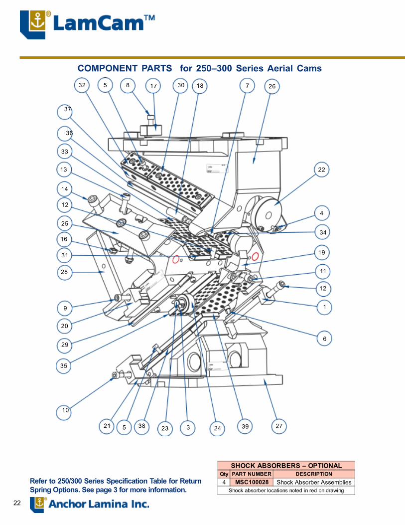
Refer to 250/300 Series Specification Table for ReturnSpring Options. See page 3 for more information.
COMPONENT PARTS for 250�300 Series Aerial Cams32 5 8 17 30 18 7 26
22
4
34
19
11
12
1
6
27392432338521
10
35
29
20
9
28
31
16
25
12
14
13
33
37
36
SHOCK ABSORBERS � OPTIONALQty PART NUMBER DESCRIPTION4 MSC100028 Shock Absorber Assemblies
Shock absorber locations noted in red on drawing
23
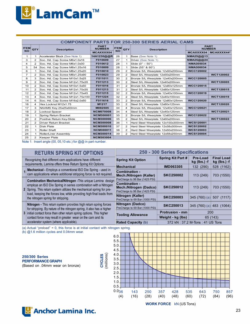
6.05.55.04.54.03.53.02.52.01.51.00.50.036
(4)143(16)
250(28)
357(40)
428(48)
535(60)
643(72)
750(84)
857(96)
WORK FORCE kN (US Tons)
CYCL
ES(m
illio
ns)
250/300 SeriesPERFORMANCE GRAPH(Based on .04mm wear on bronze)
(a) Actual �preload� = 0, this force is at initial contact with nitrogen spring.(b) @1.6 million cycles and 0.04mm wear.
Note 1: Insert angle (00, 05,10 etc.) for @@ in part number.
RETURN SPRING KIT OPTIONS Recognizing that different cam applications have different requirements, Lamina offers three Return Spring Kit Options:
1 Mechanical - Employs a conventional ISO Die Spring - used in cam applications where additional stripping force is not required.
2
Combination Mechanical/Nitrogen -This unique Lamina design employs an ISO Die Spring in series combination with a Nitrogen Spring. This return system utilizes the mechanical spring for pre- load, keeping the forces low, while providing high final loads from the nitrogen spring for stripping.
3
Nitrogen - This return system provides high return spring forces for stripping. By nature of the nitrogen spring, it also has a higher initial contact force than other return spring options. This higher contact force may result in greater wear on the cam and its accelerator system (where applicable).
250 - 300 Series SpecificationsSpring Kit Option Spring Kit Part # Pre-Load
kg (lbs.) -fFinal Loadkg (lbs.) -f
Mechanical IMD063305 132 (290) 528 (1162)Combination -Mech./Nitrogen (Kaller)PreCharge to 98 Bar (1425 PSI)
SKC250002 113 (249) 703 (1550)
Combination -Mech./Nitrogen (Dadco)PreCharge to 98 Bar (1425 PSI)
SKC250012 113 (249) 703 (1550)
Nitrogen (Kaller)PreCharge to 69 Bar (1000 PSI)
SKC250003 345 (760) (a) 507 (1117)
Nitrogen (Dadco)PreCharge to 69 Bar (1000 PSI)
SKC250013 345 (760) (a) 483 (1064)
Tooling Allowance Protrusion - mm 200Weight - kg (lbs) 65 (143)
Rated Capacity (b) 372 kN : 37.2 M-Tons : 41 US Tons
COMPONENT PARTS FOR 250-300 SERIES AERIAL CAMSITEMNO QTY Description
PARTNUMBER ITEM
NO QTY DescriptionPART
NUMBERMCAXXXX04 MCAXXXX04 MCAXXXX44*
1 1 Accelerator Block (See Note 1) 14A1230@@R 26 1 Base (See Note 1) NMA25@@133 2 Soc. Hd. Cap Screw M6x1.0x16 F010609 27 1 Driver (See Note 1) NMA25@@244 2 Soc. Hd. Cap Screw M6x1.0x30 F010612 28 1 Slide (0° � 50°) NMA3050345 54 Soc. Hd. Cap Screw M8x1.25x16 F010809 28 1 Slide (55° & 60°) NMA3060346 1 Soc. Hd. Cap Screw M8x1.25x20 F010810 29 2 Bronze S/L Wearplate 12x50x200mm WCC1200027 2 Soc. Hd. Cap Screw M8x1.25x90 F010823 29 2 Steel S/L Wearplate 12x50x200mm WCT1200028 3 Soc. Hd. Cap Screw M10x1.5x25 F011011 30 2 Bronze S/L Wearplate 12x40x200mm WCC1200059 2 Soc. Hd. Cap Screw M12x1.75x35 F011213 30 2 Steel S/L Wearplate 12x40x200mm WCT12000510 2 Soc. Hd. Cap Screw M10x1.5x50 F011016 31 2 Bronze S/L Wearplate 12x80x125mm WCC12001511 2 Soc. Hd. Cap Screw M12x1.75x35 F011213 31 2 Steel S/L Wearplate 12x80x125mm WCT12001512 2 Soc. Hd. Cap Screw M12x1.75x45 F011215 32 2 Bronze S/L Wearplate 12x40x100mm WCC12001913 4 Soc. Hd. Cap Screw M12x1.75x100 F011224 32 2 Steel S/L Wearplate 12x40x100mm WCT12001914 6 Soc. Hd. Cap Screw M16x2.0x50 F011616 33 2 Bronze S/L Wearplate 12x80x125mm WCC12002016 4 Hex Locknut M12x1.75 M1217 33 2 Steel S/L Wearplate 12x80x125mm WCT12002017 3 NAAMS Key 25x25x50mm M082505 34 4 Bronze S/L Wearplate 12x40x125mm WCC12002118 2 Lockout Spacer NCM070008 34 4 Steel S/L Wearplate 12x40x125mm WCT12002119 1 Spring Return Bracket NCM300001 35 2 Bronze S/L Wearplate 12x60x200mm WCC12002220 2 Positive Return Key-Slide NCM300006 35 2 Steel S/L Wearplate 12x60x200mm WCT12002221 2 Driver Return Bracket NCM300008 36 1 Hard Steel Wearplate 12x150x300mm WCS12000122 1 Disk Plate NCM300010 37 2 Hard Steel Wearplate 12x38x300mm WCS12000223 1 Roller Shaft NCM300011 38 2 Hard Steel Wearplate 12x50x250mm WCS12000324 1 Roller/Liner Assembly NCM300014 39 2 Hard Steel Wearplate 12x58x250mm WCS12000425 2 Keeper Plate NCM303004
24
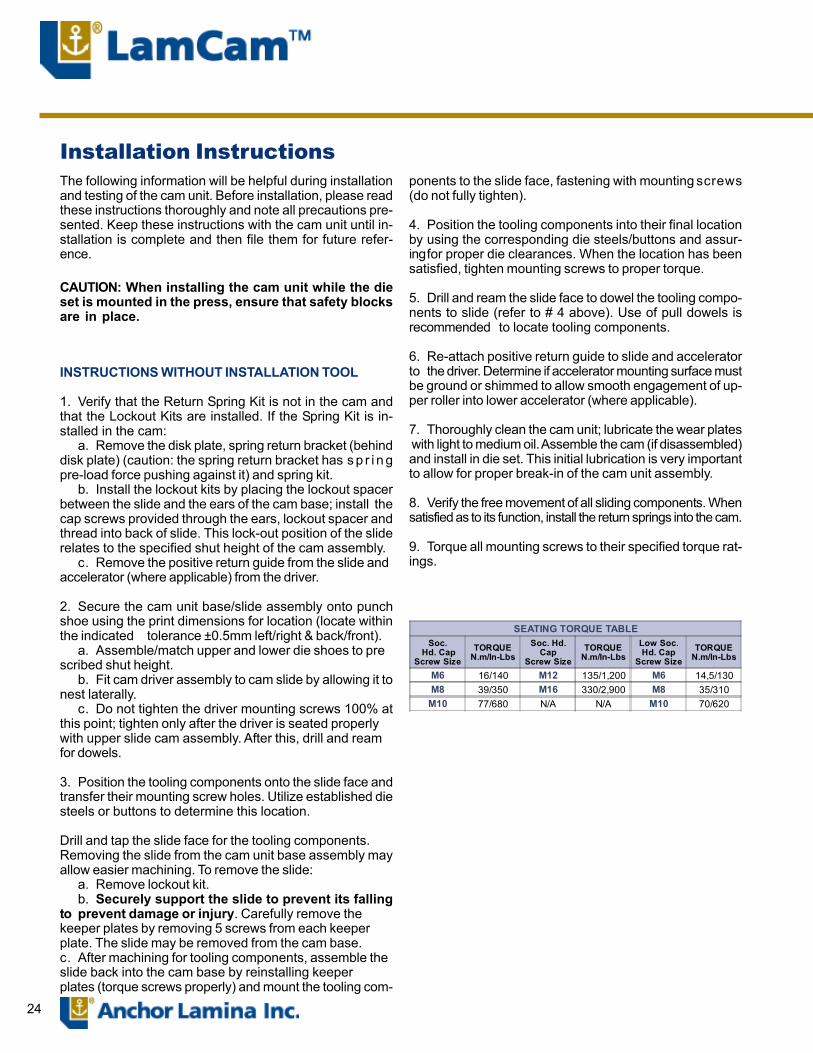
Installation InstructionsThe following information will be helpful during installationand testing of the cam unit. Before installation, please readthese instructions thoroughly and note all precautions pre-sented. Keep these instructions with the cam unit until in-stallation is complete and then file them for future refer-ence.
CAUTION: When installing the cam unit while the dieset is mounted in the press, ensure that safety blocksare in place.
INSTRUCTIONS WITHOUT INSTALLATION TOOL
1. Verify that the Return Spring Kit is not in the cam andthat the Lockout Kits are installed. If the Spring Kit is in-stalled in the cam:
a. Remove the disk plate, spring return bracket (behinddisk plate) (caution: the spring return bracket has s p r i n gpre-load force pushing against it) and spring kit.
b. Install the lockout kits by placing the lockout spacerbetween the slide and the ears of the cam base; install thecap screws provided through the ears, lockout spacer andthread into back of slide. This lock-out position of the sliderelates to the specified shut height of the cam assembly.
c. Remove the positive return guide from the slide andaccelerator (where applicable) from the driver.
2. Secure the cam unit base/slide assembly onto punchshoe using the print dimensions for location (locate withinthe indicated tolerance ±0.5mm left/right & back/front).
a. Assemble/match upper and lower die shoes to prescribed shut height.
b. Fit cam driver assembly to cam slide by allowing it tonest laterally.
c. Do not tighten the driver mounting screws 100% atthis point; tighten only after the driver is seated properlywith upper slide cam assembly. After this, drill and reamfor dowels.
3. Position the tooling components onto the slide face andtransfer their mounting screw holes. Utilize established diesteels or buttons to determine this location.
Drill and tap the slide face for the tooling components.Removing the slide from the cam unit base assembly mayallow easier machining. To remove the slide:
a. Remove lockout kit.b. Securely support the slide to prevent its falling
to prevent damage or injury. Carefully remove thekeeper plates by removing 5 screws from each keeperplate. The slide may be removed from the cam base.c. After machining for tooling components, assemble theslide back into the cam base by reinstalling keeperplates (torque screws properly) and mount the tooling com-
ponents to the slide face, fastening with mounting screws(do not fully tighten).
4. Position the tooling components into their final locationby using the corresponding die steels/buttons and assur-ingfor proper die clearances. When the location has beensatisfied, tighten mounting screws to proper torque.
5. Drill and ream the slide face to dowel the tooling compo-nents to slide (refer to # 4 above). Use of pull dowels isrecommended to locate tooling components.
6. Re-attach positive return guide to slide and acceleratorto the driver. Determine if accelerator mounting surface mustbe ground or shimmed to allow smooth engagement of up-per roller into lower accelerator (where applicable).
7. Thoroughly clean the cam unit; lubricate the wear plates with light to medium oil. Assemble the cam (if disassembled)and install in die set. This initial lubrication is very importantto allow for proper break-in of the cam unit assembly.
8. Verify the free movement of all sliding components. Whensatisfied as to its function, install the return springs into the cam.
9. Torque all mounting screws to their specified torque rat-ings.
SEATING TORQUE TABLESoc.
Hd. CapScrew Size
TORQUEN.m/In-Lbs
Soc. Hd.Cap
Screw SizeTORQUE
N.m/In-LbsLow Soc.Hd. Cap
Screw SizeTORQUE
N.m/In-Lbs
M6 16/140 M12 135/1,200 M6 14,5/130M8 39/350 M16 330/2,900 M8 35/310
M10 77/680 N/A N/A M10 70/620

25
INSTRUCTIONS USING INSTALLATION TOOLWith the use of our Installation Tool, Aerial Cams may beplaced in a fraction of the time needed to install them with-out the tool.
1. After location of the cam is determined between the up-per and lower die and the die is open and separated in thedie work area, carefully remove the slide from the cam bodyusing handling holes (if necessary).
2. Remove accelerator bracket from slide (where applicable).(55° and 60° cams do not have accelerator brackets.)
3. Remove accelerator ramp from driver (where applicable).(55° and 60° cams do not have accelerator ramps.)
4. Bolt the square bar to the center slot of the cam driver.(The tapped hole at the end of the square bar should facetoward the back of the cam away from the cam work area.)
5. Position the cam slide onto the cam driver. Let the slidenestle on the driver toward the forward position while engag-ing the external positive returns (close to the work area).
6. Attach the cam installation bracket to the back of thecam slide using the two mounting screws provided. Be surethat the slide is properly seated on wear surfaces of thedriver and at the same time the bracket should be properlyseated against bottom side of the square bar. No gap should
Adapter Plate
Punch Assembly
Slide
External Positive Returns
Square BarInstallation Bracket
Mounting Screw
10mmHex Key
Cam Driver
Adjustment Screw
For use with LaminaNAAMS Aerial 125, 150,175, 200, 250 & 300Series Cams and AerialModular Cams
NCK121500for 125 � 150Series
NCK172000for 175�200 Series
be present between the 30° wear plates of the slide anddriver. Tighten the two mounting screws securely to the slide.(It may be necessary to simultaneously push the slide tothe driver and the bracket against the bottom of the squarebar.)
7. Insert the adjustment screw in the slot provided in thebracket which will put the adjustment screw in line with thehole in the end of the square bar.
8. Use of a 10mm Hex Key or Air Rachet to rotate adjust-ment screw counter clockwise or clockwise will accuratelysimulate the slide movement on the driver for evaluating orprecise setting of punches and trim steels.
SEATING TORQUE TABLESoc.
Hd. CapScrew Size
TORQUEN.m/In-Lbs
Soc. Hd.Cap
Screw SizeTORQUE
N.m/In-LbsLow Soc.Hd. Cap
Screw SizeTORQUE
N.m/In-Lbs
M6 16/140 M12 135/1,200 M6 14,5/130M8 39/350 M16 330/2,900 M8 35/310
M10 77/680 N/A N/A M10 70/620
NCK253000for 250 � 300 Series
26
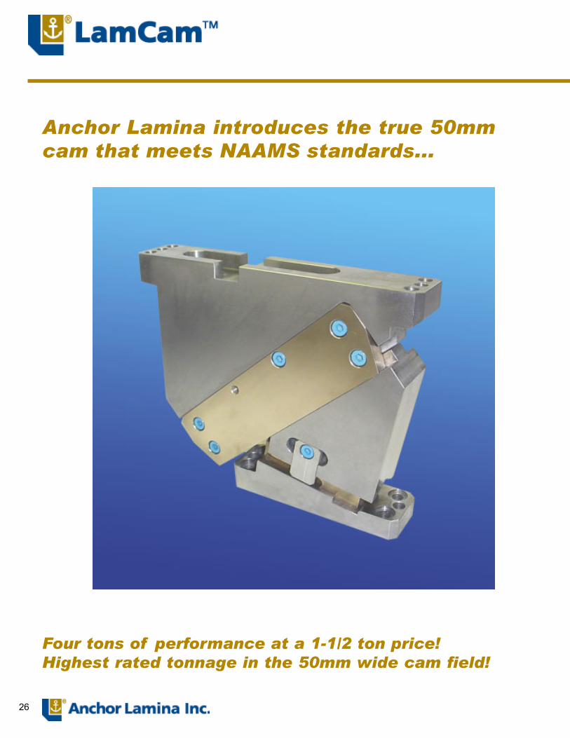
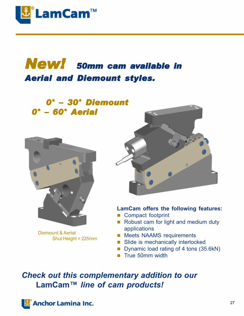
Anchor Lamina introduces the true 50mmcam that meets NAAMS standards...
Four tons of performance at a 1-1/2 ton price!Highest rated tonnage in the 50mm wide cam field!
27
NeNeNeNeNew! w! w! w! w! 50mm cam a 50mm cam a 50mm cam a 50mm cam a 50mm cam avvvvvailaailaailaailaailabbbbble inle inle inle inle in
Aerial and Diemount styles.Aerial and Diemount styles.Aerial and Diemount styles.Aerial and Diemount styles.Aerial and Diemount styles.
LamCam offers the following features:! Compact footprint! Robust cam for light and medium duty
applications! Meets NAAMS requirements! Slide is mechanically interlocked! Dynamic load rating of 4 tons (35.6kN)! True 50mm width
Check out this complementary addition to ourLamCam� line of cam products!
Diemount & AerialShut Height = 225mm
0° � 30° Diemount0° � 30° Diemount0° � 30° Diemount0° � 30° Diemount0° � 30° Diemount0° � 60° Aerial0° � 60° Aerial0° � 60° Aerial0° � 60° Aerial0° � 60° Aerial
Anchor Lamina Contacts
Lamina Components38505 Country Club Drive Suite 200Farmington Hills, MI USA 48331Tel: 248-489-9122, 800-652-6462; Fax: 248-553-6842, 800-406-4410E-mail: [email protected]
Anchor Die Sets2590 Ouellette Avenue, Windsor, ON, Canada N8X 1L7Tel: 519-966-4431, 800-265-5007; Fax: 519-966-3594E-mail: [email protected]
1450 Alphonse D-Roy, Montreal, QC, Canada H1W 2K8Tel: 514-525-5560, 800-263-5560; Fax: 514-525-7835E-mail: [email protected]
1200 Lakeshore Road East, Mississauga, ON, Canada L5E 1E9Tel: 905-274-3448, 800-268-5230; Fax: 905-274-7303E-mail: [email protected]
311 Pinebush Road, Cambridge, ON, Canada N1T 1B2Tel: 519-740-3060, 800-265-7842 (Canada only); Fax: 519-740-8213E-mail: [email protected]
95 East Ten Mile Road, Madison Heights, MI USA 48071Tel: 248-547-5910, 800-543-3790; Fax: 248-547-5918, 800-963-0400E-mail: [email protected]
4300 40th Street, S.E., Kentwood, MI USA 49512Tel: 616-949-8700, 888-526-2467; Fax: 616-949-9580E-mail: [email protected]
Reliance Fabrications95 Lyon Avenue North, Tilbury, ON, Canada N0P 2L0Tel: 519-682-0470, 800-265-5295; Fax: 519-682-3616E-mail: [email protected]
www.anchorlamina.com
Committed to Quality & Customer Satisfaction
Anchor Lamina is committed to be the �customerfocused� world-class supplier of choice to the metal-working and plastics forming industry.
We will help our customers to compete globally byproviding innovative and value added products andservices.
075-0804-1m
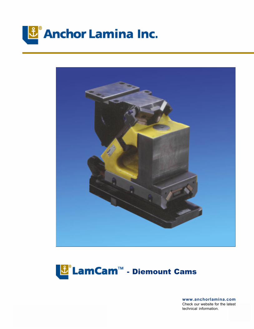
- Diemount Cams
www.anchorlamina.comCheck our website for the latesttechnical information.

2
!!!!! Ease of spring replacement from back of cam; the cam base incorporates a safety restraint system to retainthe slide during spring removal
!!!!! High quality materials used throughout, including high-strength steel castings for major components
!!!!! All wear areas are double-plated with self-lubricated wear plates to reduce maintenance andaccommodate high production volumes
!!!!! Three Return Spring Kit options are available: mechanical ISO spring, combination mechanical/nitrogen springs and nitrogen spring
!!!!! Pentahedron design ensures smooth and stable slide movement on 125 through 300 Series Cams
!!!!! Dual external positive return system; Urethane bumper cushion on slide return
!!!!! Mounting/locating provisions include both square keys and dowel holes
!!!!! Meets or exceeds all of �NAAMS� cam requirements
!!!!! Lock-out kit installed, ready for cam installation and set up
!!!!! Safety back-up provisions for retaining keeper plates
!!!!! Improved, super-duty accelerator system standard on 0° through 30° angles
!!!!! Optional hydraulic shock absorber available
TABLE OF CONTENTS
Introduction ...................................................... 2
General Information ......................................... 3
50 Series Cams .............................................. 4
75 Series Cams .............................................. 8
125-150 Series Cams ..................................... 12
175-200 Series Cams ..................................... 16
250-300 Series Cams ..................................... 20
Installation Instructions ..................................... 24
Anchor Lamina has made a commitment to themetal stamping industry by manufacturing and dis-tributing a comprehensive collection of high qual-ity products.
Lamina has long been known for expertise in pro-ducing precision products and has applied thatknowledge into the design and production of camswith truly interchangeable parts. LamCams�maintain consistency throughout standard linesavailable from bump cams to Aerial and Diemountcams to large Modular Styles.
Input from our customers has been and continuesto be an important part of cam development andmaintenance which assures Lamina�s leadershipposition.
No other company surpasses our obligation to you,our customer, in supporting cam products. We lis-ten to your needs and respond when you require ourassistance.
3
Mechanical Spring
Mechanical & Nitrogen Spring*(Recommended)
Nitrogen Spring
SLIDE RETURN SYSTEM OPTIONS
Recognizing that different cam applications have differentrequirements, Lamina offers three Slide Return SystemOptions.
1. Mechanical � Employs a conventional ISO die spring, usedin cam applications where additional stripping force is notrequired.
2. Combination Mechanical/Nitrogen � This unique Laminadesign employs an ISO die spring in series combination witha Nitrogen Spring. This return system utilizes the mechanicalspring for preload, keeping the contact forces low, while pro-viding high final loads from the nitrogen spring for stripping.
3. Nitrogen � This return system provides high return springforces for stripping. By nature of the nitrogen spring, it also hasa higher initial contact force than other return spring options.This higher contact force may result in greater wear on thecam and its accelerator system (where applicable).
*Lamina strongly recommends the use of the Nitro-gen Cylinder/Mechanical Spring Combination Systemfor the slide return function of all Aerial and Diemountcam units.
The benefit of using the Combination System is two-fold:
1. The force developed in the slide return system is low whenthe accelerator function is active (because only the mechani-cal spring is operative at that point), thus, wearing of the accel-erator components is greatly reduced.
2. The total developed slide return force at the cam�s shutheight position is greater with the Combination System than itis with the Nitrogen-only option. The result is more on-boardcapability for part stripping.
OPTIONAL SHOCK ABSORBERSPART NUMBER KEY
NAAMS Diemount
CamFamily Face
Width(Series)
WorkAngle
(degrees)
Generation
Optional Shock Absorber
Optional shock absorbers areavailable and should be used inthe absence of an accelerator sys-tem on low-angle cams (i.e., lessthan 35°) to ensure a gentle returnof the slide to its home position.
Shock Absorber withM6x12 Set Screw

4
X5
X8 ±0.013 Dowels10 (±0.013 Dowel)
DRIVER(25° & 30°)
70(±0.013Dowels)
90
Ø12 S.H.C.S. (3)Ø12 Dowel (H7) (2)
Ø12 S.H.C.S. (2)X8 (±0.013 Dowels)
10 (±0.013 Dowel)
70(±0.013Dowels)
90DRIVER(0° � 20°)
X5
AX5
225 ±0.5
X4(A to B)(+Dim =B Right)
12Ref
20 ±0.25Ø10 (H7)42.5 ±0.25
Ø6 (H7)Z1
12
Angle
X7
X6
X3
25 Typ.
B
X2 (Dowel ±0.013)
X1 ±0.025
52 80BASE(Body)
Ø12 S.H.C.S. (4)Ø12 (H7) Dowel (4)
1126
26
9547.5
Z2
90
40 ±0.25
SLIDE
Tooling Ball offset from center.(-Dim = T.B. below center)NOTE: T.B. (NAAMS M011222),is for reference only; part andmounting provisions not included.
DIEMOUNT CAMDIEMOUNT CAMDIEMOUNT CAMDIEMOUNT CAMDIEMOUNT CAM50 Series
12 (Dowel ±0.013)
STROKE
ANGLE PRESSSTROKE
WORKSTROKE
0 53.6 45 5 48.8 4510 45.0 4515 42.1 4520 39.8 4525 38.0 4530 36.7 45
5
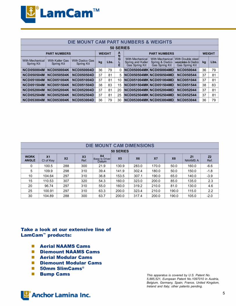
DIE MOUNT CAM DIMENSIONS50 SERIES
WORKANGLE
X1Cl of Key X2 X3
Ref.X4
Base to DriverDatum
X5 X6 X7 X8 Z1NAAMS A
Z2Ref.
0 100.5 288 300 21.9 130.9 283.0 170.0 50.0 160.0 -6.6 5 109.9 298 310 39.4 141.9 302.4 180.0 50.0 150.0 -1.810 104.64 297 310 36.8 153.5 307.1 190.0 65.0 140.0 -3.915 110.53 307 320 54.3 160.0 323.0 200.0 85.0 135.0 2.320 96.74 297 310 55.0 160.0 319.2 210.0 81.0 130.0 4.625 100.91 297 310 63.3 200.0 323.4 210.0 190.0 115.0 2.230 104.89 288 300 63.7 200.0 317.4 200.0 190.0 105.0 -2.0
DIE MOUNT CAM PART NUMBERS & WEIGHTS50 SERIES
PART NUMBERS WEIGHT ANGLE
PART NUMBERS WEIGHT
With MechanicalSpring Kit
With Kaller GasSpring Kit
With Dadco GasSpring Kit kg Lbs.
With MechanicalSpring and Kaller
Gas Spring Kit
With MechanicalSpring & DadcoGas Spring Kit
With Double steelwearplates & Dadco
Gas Spring Kitkg Lbs.
NCD050004M NCD050004K NCD050004D 36 79 0 NCD050004MK NCD050004MD NCD050044 36 79NCD050504M NCD050504K NCD050504D 37 81 5 NCD050504MK NCD050504MD NCD050544 37 81NCD051004M NCD051004K NCD051004D 37 81 10 NCD051004MK NCD051004MD NCD051044 37 81NCD051504M NCD051504K NCD051504D 38 83 15 NCD051504MK NCD051504MD NCD051544 38 83NCD052004M NCD052004K NCD052004D 37 81 20 NCD052004MK NCD052004MD NCD052044 37 81NCD052504M NCD052504K NCD052504D 37 81 25 NCD052504MK NCD052504MD NCD052544 37 81NCD053004M NCD053004K NCD053004D 36 79 30 NCD053004MK NCD053004MD NCD053044 36 79
Take a look at our extensive line ofLamCam� products:
! Aerial NAAMS Cams! Diemount NAAMS Cams! Aerial Modular Cams! Diemount Modular Cams! 50mm SlimCams®
! Bump Cams This apparatus is covered by U.S. Patent No.5,885,521, European Patent No.1097010 in Austria,Belgium, Germany, Spain, France, United Kingdom,Ireland and Italy; other patents pending.

6
Refer to 50 Series Specifications Table for Return Spring Options. See page 3 for more information.
COMPONENT PARTS for 50 Series Diemount Cams
13 19 12
23
16
8
18
6
2
5
4
17
10811222115
24
20
7
14
3
7
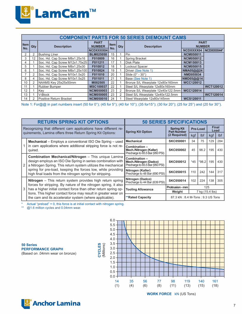
COMPONENT PARTS FOR 50 SERIES DIEMOUNT CAMSItemNo. Qty Description
PARTNUMBER Item
No. Qty DescriptionPART
NUMBERNCDXXXX04 NCDXXXX04 NCDXXXX44*
2 2 Bushing LIner BLM025050 15 1 Pin NCM0500113 12 Soc. Hd. Cap Screw M8x1.25x16 F010809 16 1 Spring Bracket NCM0500124 1 Soc. Hd. Cap Screw M12x1.75x25 F011211 17 1 Disk Plate NCM1500135 1 Soc. Hd. Cap Screw M8x1.25x30 F010812 18 1 Lockout Spacer NCM0500156 1 Soc. Hd. Cap Screw M8x1.25x100 F010824 19 1 Driver (See Note 1) NMA05@@247 2 Soc. Hd. Cap Screw M10x1.5x20 F011010 20 1 Slide (0° - 30°) NMD0550348 4 Soc. Hd. Cap Screw M10x1.5x25 F011011 21 1 Base (See Note 1) NMD05@@14
10 2 NAAMS Key 25x25x50mm M082505 22 1 Bronze S/L Wearplate 12x80x160mm WCC12001211 1 Rubber Bumper MSC100037 22 1 Steel S/L Wearplate 12x80x160mm WCT12001212 1 Key NCM050003 23 2 Bronze S/L Wearplate 12x40x122.5mm WCC12001413 1 V-Block NCM050005 23 2 Steel S/L Wearplate 12x40x122.5mm WCT12001414 2 Positive Return Bracket NCM050010 24 1 Steel Wearplate 12x80x145mm WCS120011
Note 1: For@@ in part numbers insert (50 for 0°); (45 for 5°); (40 for 10°); (35 for15°); (30 for 20°); (25 for 25°) and (20 for 30°).
RETURN SPRING KIT OPTIONSRecognizing that different cam applications have different re-quirements, Lamina offers three Return Spring Kit Options:
1Mechanical – Employs a conventional ISO Die Spring – used in cam applications where additional stripping force is not re-quired.
2
Combination Mechanical/Nitrogen – This unique Lamina design employs an ISO Die Spring in series combination with a Nitrogen Spring. This return system utilizes the mechanical spring for pre-load, keeping the forces low, while providing high fi nal loads from the nitrogen spring for stripping.
3
Nitrogen – This return system provides high return spring forces for stripping. By nature of the nitrogen spring, it also has a higher initial contact force than other return spring op-tions. This higher contact force may result in greater wear on the cam and its accelerator system (where applicable).
50 SERIES SPECIFICATIONS
Spring Kit OptionSpring Kit
Part Number(2 Required)
Pre-Load Final Load
kgf lbf kgf lbfMechanical SKC050001 34 75 129 284
Combination – Mech./Nitrogen (Kaller)Precharge to 65.5 Bar (950 PSI)
SKC050002 45 98.2 195 430
Combination – Mech./Nitrogen (Dadco)Precharge to 65.5 Bar (950 PSI)
SKC050012 *45 *98.2 195 430
Nitrogen (Kaller)Precharge to 48 Bar (690 PSI) SKC050015 110 242 144 317
Nitrogen (Dadco)Precharge to 44 Bar (639 PSI) SKC050014 102 224 138 305
Tooling Allowance Protrusion - mm 125Weight 7 kg (15.4 lbs)
**Rated Capacity 87.3 kN : 8.4 M-Tons : 9.3 US Tons
* Actual “preload” = 0, this force is at initial contact with nitrogen spring.** @1.6 million cycles and 0.04mm wear.
50 SeriesPERFORMANCE GRAPH(Based on .04mm wear on bronze)
6.05.55.04.54.03.53.02.52.01.51.00.50.0
CYC
LES
(Mill
ions
)
14(1)
35(4)
56(6)
77(8)
98(11)
119(13)
140(15)
161(18)
WORK FORCE kN (US Tons)
8
X5
85 110
13 Dowel ±0.013
DRIVER(30° only)
DRIVER(0° � 25°)
X9 ±0.013
X8
85(±0.013Dowels)
110
13
Ø12 Dowels (2)Ø12 S.H.C.S. (4)
X9 (±0.013)X8
X5 A
20 ±0.025
Ø10 (H7)
275 ±0.5
Angle
25 Typ.
BX6X7
X3
Z1
X2 (Dowel ±0.013)
12
Ø12 S.H.C.S. (4)
Ø12 Dowels (H7) (2)
22.5
X1 ±0.02513 (Dowel ±0.013)
1108525BASE
(Body)
115
10552.5
47.5 ±0.25
Ø6 (H7)
52.5 ±0.25Z2*
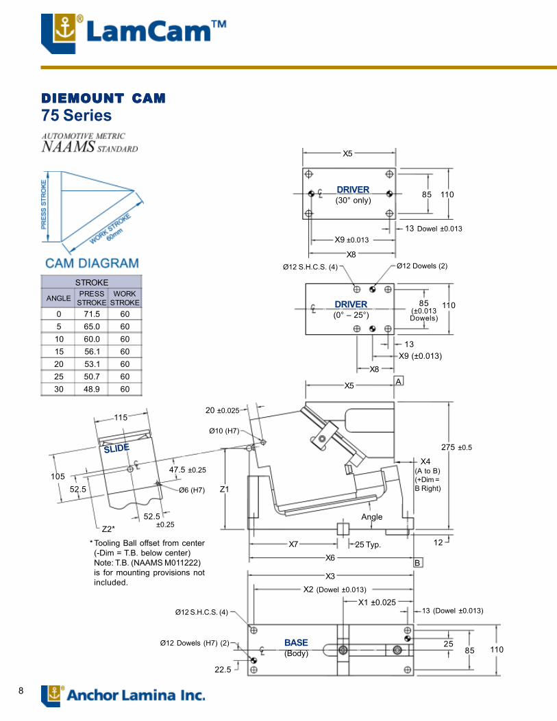
Tooling Ball offset from center(-Dim = T.B. below center)Note: T.B. (NAAMS M011222)is for mounting provisions notincluded.
*
DIEMOUNT CAMDIEMOUNT CAMDIEMOUNT CAMDIEMOUNT CAMDIEMOUNT CAM75 Series
SLIDE
STROKE
ANGLE PRESSSTROKE
WORKSTROKE
0 71.5 605 65.0 6010 60.0 6015 56.1 6020 53.1 6025 50.7 6030 48.9 60
X4(A to B)(+Dim =B Right)
9
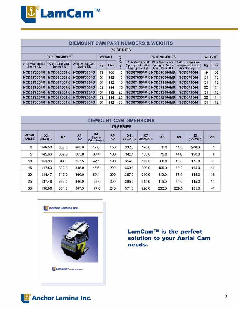
DIEMOUNT CAM PART NUMBERS & WEIGHTS75 SERIES
PART NUMBERS WEIGHT ANGLE
PART NUMBERS WEIGHT
With MechanicalSpring Kit
With Kaller GasSpring Kit
With Dadco GasSpring Kit kg Lbs.
With MechanicalSpring and Kaller
Gas Spring Kit
With MechanicalSpring & DadcoGas Spring Kit
With Double steelwearplates & Dadco
Gas Spring Kitkg Lbs.
NCD070004M NCD070004K NCD070004D 49 108 0 NCD070004MK NCD070004MD NCD070044 49 108NCD070504M NCD070504K NCD070504D 51 112 5 NCD070504MK NCD070504MD NCD070544 51 112NCD071004M NCD071004K NCD071004D 51 112 10 NCD071004MK NCD071004MD NCD071044 51 112NCD071504M NCD071504K NCD071504D 52 114 15 NCD071504MK NCD071504MD NCD071544 52 114NCD072004M NCD072004K NCD072004D 51 112 20 NCD072004MK NCD072004MD NCD072044 51 112NCD072504M NCD072504K NCD072504D 52 114 25 NCD072504MK NCD072504MD NCD072544 52 114NCD073004M NCD073004K NCD073004D 51 112 30 NCD073004MK NCD073004MD NCD073044 51 112
DIEMOUNT CAM DIMENSIONS 75 SERIES
WORKANGLE
X1(Cl of Key) X2 X3
Ref
X4Base to
Driver Datum
X5Ref
X6(NAAMS E)
X7(NAAMS C)
X8 X9 Z1(NAAMS A) Z2
0 149.50 352.0 365.0 47.6 150 332.0 170.0 70.0 41.5 200.0 4
5 149.60 352.0 365.0 30.4 180 342.1 180.0 75.0 44.0 190.0 1
10 151.96 344.5 357.5 42.1 190 354.5 190.0 80.0 46.5 175.0 -8
15 147.50 332.0 345.0 45.6 200 360.0 200.0 105.0 80.0 165.0 -11
20 144.47 347.0 360.0 60.4 200 367.0 210.0 110.0 85.0 155.0 -13
25 137.48 333.0 346.0 68.0 200 365.0 215.0 115.0 94.0 145.0 -15
30 138.96 334.5 347.5 77.0 245 371.5 220.0 232.0 229.0 135.0 -7
LamCam� is the perfectsolution to your Aerial Camneeds.
10
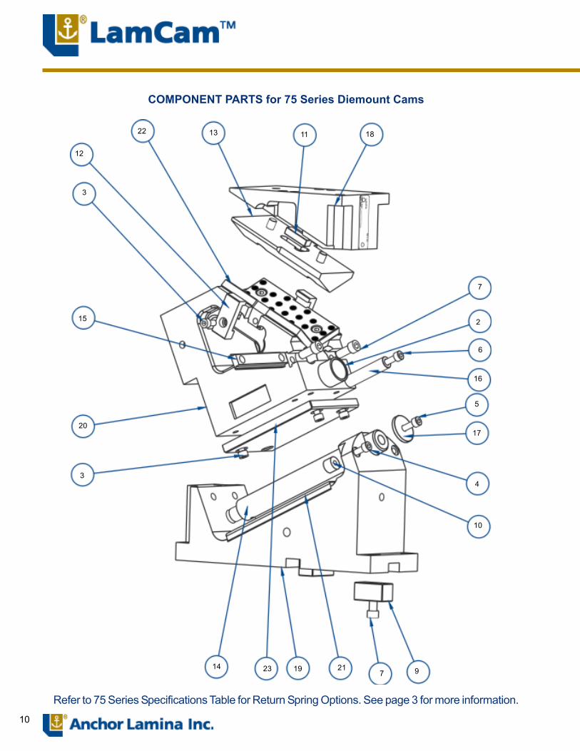
COMPONENT PARTS for 75 Series Diemount Cams
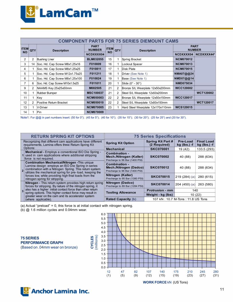
Refer to 75 Series Specifications Table for Return Spring Options. See page 3 for more information.
22 13 11 18
12
3
15
20
3
14 23 19 217 9
16
5
17
4
10
7
2
6
11
(a) Actual �preload� = 0, this force is at initial contact with nitrogen spring.(b) @ 1.6 million cycles and 0.04mm wear.
75 SERIESPERFORMANCE GRAPH(Based on .04mm wear on bronze)
6.05.55.04.54.03.53.02.52.01.51.00.50.0
280(31)
245(27)
210(23)
175(19)
140(15)
107(12)
82(9)
47(5)
12(1)
WORK FORCE kN (US Tons)
CYCL
ES(m
illio
ns)
75 Series Specifications Spring Kit Option Spring Kit Part #
(2 Required) Pre-Loadkg (lbs.) -f
Final Loadkg (lbs.) -f
Mechanical SKC070001 19 (42) 133.5 (293) Combination - Mech./Nitrogen (Kaller) Precharge to 96 Bar (1400 PSI)
SKC070002 40 (88) 288 (634)
Combination - Mech./Nitrogen (Dadco) Precharge to 96 Bar (1400 PSI)
SKC070012 40 (88) 288 (634)
Nitrogen (Kaller) Precharge to 95 Bar (1380 PSI)
SKC070015 219 (284) (a) 280 (615)
Nitrogen (Dadco) Precharge to 89 Bar (1284 PSI)
SKC070014 204 (450) (a) 263 (580)
Tooling Allowance Protrusion - mm 140Weight - kg (lbs) 10 (22)
Rated Capacity (b) 107 kN : 10.7 M-Tons : 11.8 US Tons
RETURN SPRING KIT OPTIONS Recognizing that different cam applications have different requirements, Lamina offers three Return Spring Kit Options:
1 Mechanical - Employs a conventional ISO Die Spring - used in cam applications where additional strippingforce is not required.
2
Combination Mechanical/Nitrogen -This unique Lamina design employs an ISO Die Spring in series combination with a Nitrogen Spring. This return system utilizes the mechanical spring for pre- load, keeping the forces low, while providing high final loads from the nitrogen spring for stripping.
3
Nitrogen - This return system provides high return spring forces for stripping. By nature of the nitrogen spring, it also has a higher initial contact force than other return spring options. This higher contact force may result in greater wear on the cam and its accelerator system (where applicable).
Note1: For @@ in part numbers insert: (50 for 0°); (45 for 5°); (40 for 10°); (35 for 15°); (30 for 20°); (25 for 25°) and (20 for 30°).
COMPONENT PARTS FOR 75 SERIES DIEMOUNT CAMSITEMNO QTY Description
PARTNUMBER ITEM
NO QTY DescriptionPART
NUMBERNCDXXXX04 NCDXXXX04 NCDXXXX44*
2 2 Bushing Liner BLM032055 15 1 Spring Bracket NCM0700123 14 Soc. Hd. Cap Screw M8x1.25x16 F010809 16 1 Lockout Spacer NCM0700134 1 Soc. Hd. Cap Screw M8x1.25x25 F010811 17 1 Disk Plate NCM0700155 1 Soc. Hd. Cap Screw M12x1.75x25 F011211 18 1 Driver (See Note 1) NMA07@@246 1 Soc. Hd. Cap Screw M8x1.25x100 F010824 19 1 Base (See Note 1) NMD07@@147 6 Soc. Hd. Cap Screw M10x1.5x25 F011011 20 1 Slide (0° - 30°) NMD0750349 2 NAAMS Key 25x25x50mm M082505 21 2 Bronze S/L Wearplate 12x50x200mm WCC12000210 1 Rubber Bumper MSC100037 21 2 Steel S/L Wearplate 12x50x200mm WCT12000211 1 Key NCM050003 22 2 Bronze S/L Wearplate 12x50x150mm WCC12001712 2 Positive Return Bracket NCM050010 22 2 Steel S/L Wearplate 12x50x150mm WCT12001713 1 V-Driver NCM070005 23 1 Hard Steel Wearplate 12x170x110mm WCS12001514 1 Pin NCM070009
12
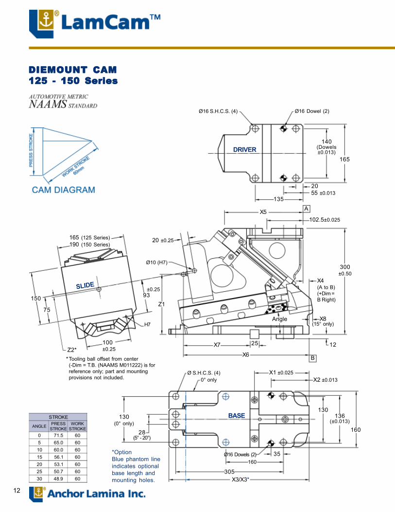
DIEMOUNT CAMDIEMOUNT CAMDIEMOUNT CAMDIEMOUNT CAMDIEMOUNT CAM125 - 150 Series125 - 150 Series125 - 150 Series125 - 150 Series125 - 150 Series
X3/X3*
STROKE
ANGLE PRESSSTROKE
WORKSTROKE
0 71.5 605 65.0 6010 60.0 6015 56.1 6020 53.1 6025 50.7 6030 48.9 60
Ø16 S.H.C.S. (4) Ø16 Dowel (2)
140(Dowels±0.013)
165
2055 ±0.013
135AX5
102.5±0.025
X4(A to B)(+Dim =B Right)
300±0.50
X8(15° only)
1225
BX6
Angle
X1 ±0.025X2 ±0.013
X7
Ø S.H.C.S. (4)0° only
130136
(±0.013)
160
35Ø16 Dowels (2)
305
130(0° only)
28(5° - 20°)
Z193
±0.25
100±0.25
H7
Z2*
75
150
Tooling ball offset from center(-Dim = T.B. (NAAMS M011222) is forreference only; part and mountingprovisions not included.
*
165 (125 Series)190 (150 Series)
20 ±0.25
Ø10 (H7)
SLIDE
DRIVER
BASE
*OptionBlue phantom lineindicates optionalbase length andmounting holes.
160
13
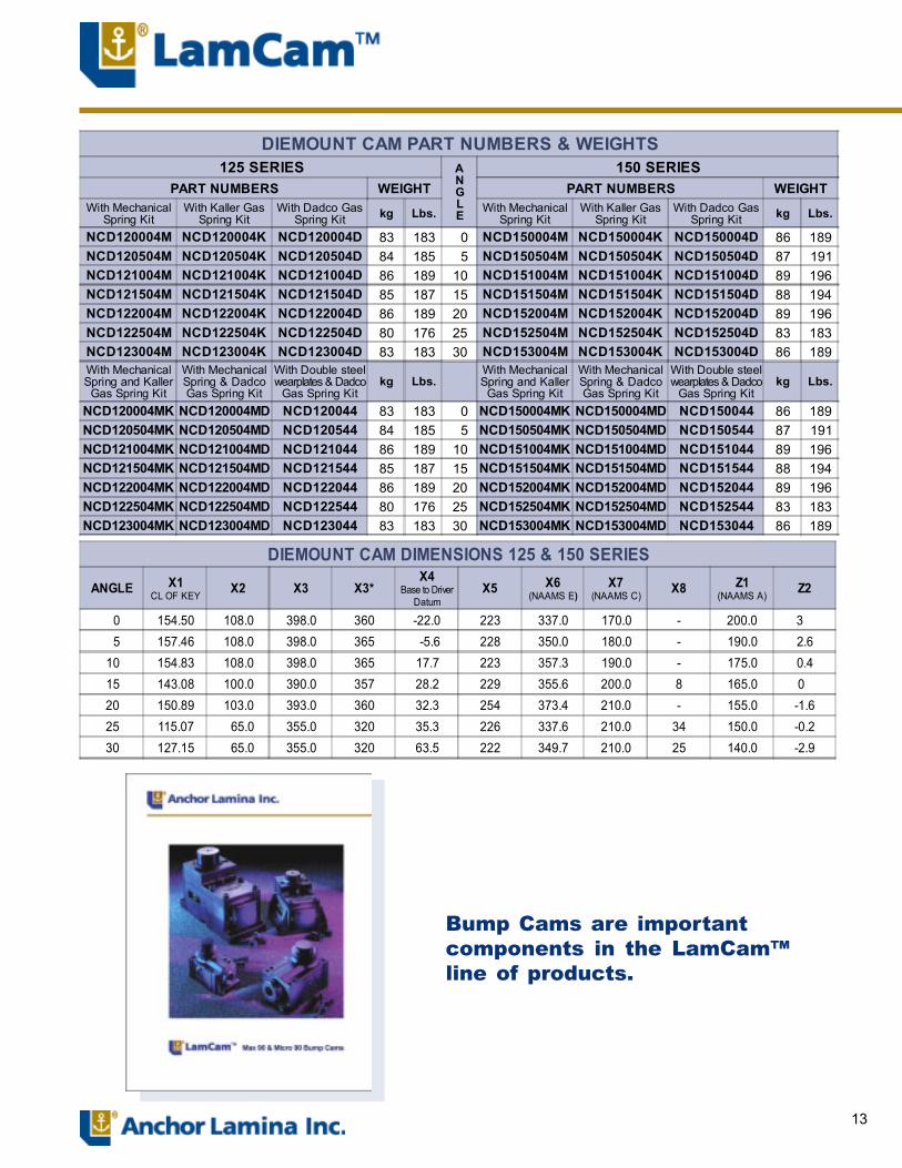
DIEMOUNT CAM DIMENSIONS 125 & 150 SERIES
ANGLE X1CL OF KEY X2 X3 X3*
X4Base to Driver
DatumX5 X6
(NAAMS E)X7
(NAAMS C) X8 Z1(NAAMS A) Z2
0 154.50 108.0 398.0 360 -22.0 223 337.0 170.0 - 200.0 3 5 157.46 108.0 398.0 365 -5.6 228 350.0 180.0 - 190.0 2.610 154.83 108.0 398.0 365 17.7 223 357.3 190.0 - 175.0 0.415 143.08 100.0 390.0 357 28.2 229 355.6 200.0 8 165.0 0 20 150.89 103.0 393.0 360 32.3 254 373.4 210.0 - 155.0 -1.625 115.07 65.0 355.0 320 35.3 226 337.6 210.0 34 150.0 -0.230 127.15 65.0 355.0 320 63.5 222 349.7 210.0 25 140.0 -2.9
Bump Cams are importantcomponents in the LamCam�line of products.
DIEMOUNT CAM PART NUMBERS & WEIGHTS125 SERIES A
NGLE
150 SERIESPART NUMBERS WEIGHT PART NUMBERS WEIGHT
With MechanicalSpring Kit
With Kaller GasSpring Kit
With Dadco GasSpring Kit kg Lbs. With Mechanical
Spring KitWith Kaller Gas
Spring KitWith Dadco Gas
Spring Kit kg Lbs.
NCD120004M NCD120004K NCD120004D 83 183 0 NCD150004M NCD150004K NCD150004D 86 189NCD120504M NCD120504K NCD120504D 84 185 5 NCD150504M NCD150504K NCD150504D 87 191NCD121004M NCD121004K NCD121004D 86 189 10 NCD151004M NCD151004K NCD151004D 89 196NCD121504M NCD121504K NCD121504D 85 187 15 NCD151504M NCD151504K NCD151504D 88 194NCD122004M NCD122004K NCD122004D 86 189 20 NCD152004M NCD152004K NCD152004D 89 196NCD122504M NCD122504K NCD122504D 80 176 25 NCD152504M NCD152504K NCD152504D 83 183NCD123004M NCD123004K NCD123004D 83 183 30 NCD153004M NCD153004K NCD153004D 86 189With MechanicalSpring and Kaller
Gas Spring Kit
With MechanicalSpring & DadcoGas Spring Kit
With Double steelwearplates & Dadco
Gas Spring Kitkg Lbs.
With MechanicalSpring and KallerGas Spring Kit
With MechanicalSpring & DadcoGas Spring Kit
With Double steelwearplates & Dadco
Gas Spring Kitkg Lbs.
NCD120004MK NCD120004MD NCD120044 83 183 0 NCD150004MK NCD150004MD NCD150044 86 189NCD120504MK NCD120504MD NCD120544 84 185 5 NCD150504MK NCD150504MD NCD150544 87 191NCD121004MK NCD121004MD NCD121044 86 189 10 NCD151004MK NCD151004MD NCD151044 89 196NCD121504MK NCD121504MD NCD121544 85 187 15 NCD151504MK NCD151504MD NCD151544 88 194NCD122004MK NCD122004MD NCD122044 86 189 20 NCD152004MK NCD152004MD NCD152044 89 196NCD122504MK NCD122504MD NCD122544 80 176 25 NCD152504MK NCD152504MD NCD152544 83 183NCD123004MK NCD123004MD NCD123044 83 183 30 NCD153004MK NCD153004MD NCD153044 86 189

14
COMPONENT PARTS for 125�150 Series Diemount Cams
Refer to 125�150 Series Specifications Table for ReturnSpring Options. See page 3 for more information.
4920
8 1
7
26
33
14
25
12
31
19
10
18
5
23
3
17
301116
27
32
6
35
34
13
22
24
29
21
28SHOCK ABSORBERS � OPTIONAL
Qty PART NUMBER DESCRIPTION2 MSC100028 Shock Absorber Assemblies
Shock absorber location noted in red on drawing

15
(a) Actual �preload� = 0, this force is at initial contact with nitrogen spring.(b) @ 1.6 million cycles and 0.04mm wear
125�150 SERIESPERFORMANCE GRAPH(Based on .04mm wear on bronze)
6.05.55.04.54.03.53.02.52.01.51.00.50.0
336(37)
294(32)
252(28)
210(23)
177(19)
140(15)
98(11)
56(6)
14(1)
CY
CLE
S(m
illio
ns)
WORK FORCE kN (US Tons)
Note1: For @@ in part numbers insert: (50 for 0°); (45 for 5°); (40 for 10°); (35 for 15°); (30 for 20°); (25 for 25°) and (20 for 30°).
125 - 150 Series SpecificationsSpring Kit Option Spring Kit Part #
(2 Required) Pre-Loadkg (lbs.) -f
Final Loadkg (lbs.) -f
Mechanical ILD040254 45 (99) 149 (328)Combination -Mech./Nitrogen (Kaller)PreCharge to 150 Bar (2175 PSI)
SKC120002 33 (73) 361 (797)
Combination -Mech./Nitrogen (Dadco)PreCharge to 150 Bar (2175 PSI)
SKC120012 33 (73) 361 (797)
Nitrogen (Kaller)PreCharge to 121 Bar (1750 PSI)
SKC120003 276 (609) (a) 373 (822)
Nitrogen (Dadco)PreCharge to 121 Bar (1750 PSI)
SKC120013 276 (609) (a) 348 (767)
Tooling Allowance Protrusion - mm 150Weight - kg (lbs) 20 (44)
Rated Capacity (b) 176 kN : 17.7 M-Tons : 19.5 US Tons
RETURN SPRING KIT OPTIONS Recognizing that different cam applications have different requirements, Lamina offers three Return Spring Kit Options:
1 Mechanical - Employs a conventional ISO Die Spring - used in cam applications where additional strippingforce is not required.
2
Combination Mechanical/Nitrogen -This unique Lamina design employs an ISO Die Spring in series combination with a Nitrogen Spring. This return system utilizes the mechanical spring for pre- load, keeping the forces low, while providing high final loads from the nitrogen spring for stripping.
3
Nitrogen - This return system provides high return spring forces for stripping. By nature of the nitrogen spring, it also has a higher initial contact force than other return spring options. This higher contact force may result in greater wear on the cam and its accelerator system (where applicable).
COMPONENT PARTS FOR 125-150 SERIES DIEMOUNT CAMSITEMNO QTY Description
PARTNUMBER ITEM
NO QTY DescriptionPART
NUMBERNCDXXXX04 NCDXXXX04 NCDXXXX44*
1 1 Accelerator Block (See Note 1) 14A1230@@R 22 2 Keeper Plate NCM1500103 1 Soc. Hd. Cap Screw M6x1.0x12 F010608 23 1 Disk Plate NCM1500144 2 Soc. Hd. Cap Screw M6x1.0x16 F010609 24 1 Roller Shaft NCM3000115 2 Soc. Hd. Cap Screw M6x1.0x20 F010610 25 1 Roller/Liner Assembly NCM300014
6 3 Soc. Hd. Cap Screw M8x1.25x10 F010807 26 1 Driver (See Note 1) NMA12@@247 35 Soc. Hd. Cap Screw M8x1.25x16 F010809 27 1 Slide (0° � 30°) NMD1550348 3 Soc. Hd. Cap Screw M8x1.25x20 F010810 28 1 Base (See Note 1) NMD12@@139 4 Soc. Hd. Cap Screw M8x1.25x40 F010814 29 2 Bronze S/L Wearplate 12x50x200mm WCC12000210 2 Soc. Hd. Cap Screw M8x1.25x90 F010823 29 2 Steel S/L Wearplate 12x50x200mm WCT12000211 3 Soc. Hd. Cap Screw M10x1.5x25 F011011 30 2 Bronze S/L Wearplate 12x30x160mm WCC12000612 2 Soc. Hd. Cap Screw M12x1.50x30 F011012 30 2 Steel S/L Wearplate 12x30x160mm WCT12000613 6 Soc. Hd. Cap Screw M12x1.75x35 F011213 31 6 Bronze S/L Wearplate 12x30x125mm WCC12000914 1 Soc. Hd. Cap Screw M12x1.75x45 F011215 31 6 Steel S/L Wearplate 12x30x125mm WCT12000916 3 NAAMS Key 25x25x50mm M082505 32 1 Bronze S/L Wearplate 12x50x225mm WCC12001117 1 Rubber Bumpers MSC100003 32 1 Steel S/L Wearplate 12x50x225mm WCT12001118 2 Lockout Spacer NCM070008 33 2 Steel Wearplate 12x30x285mm WCS12000819 1 Spring Return Bracket NCM150001 34 1 Steel Wearplate 12x48x280mm WCS12001020 2 Positive Return Bracket NCM150008 35 1 Steel Wear Plate 12x48x225mm WCS12001221 2 Positive Return Guideway NCM150009
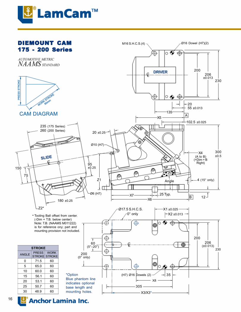
16
DIEMOUNT CAMDIEMOUNT CAMDIEMOUNT CAMDIEMOUNT CAMDIEMOUNT CAM175 - 200 Series175 - 200 Series175 - 200 Series175 - 200 Series175 - 200 Series
DRIVER
M16 S.H.C.S.(4) Ø16 Dowel (H7)(2)
230
206±0.013
200
2055 ±0.013
135X5 A
102.5 ±0.025
X4(A to B)
(+Dim = BRight)
300±0.5
4 (15° only)Angle
12BX7X6
25 Typ.
Z1
95±0.25
180 ±0.25
SLIDE
150
75
Z2*
Tooling Ball offset from center.(-Dim = T.B. below center)Note: T.B. (NAAMS M011222)is for reference ony; part andmounting provision not included.
*
Ø17.5 S.H.C.S.0° only
X1 ±0.025X2 ±0.013
200206
(±0.013)60
(5°�20°)
200(0° only)
(H7) Ø16 Dowels (2) 35
305
X3/X3*
STROKE
ANGLE PRESSSTROKE
WORKSTROKE
0 71.5 605 65.0 6010 60.0 6015 56.1 6020 53.1 6025 50.7 6030 48.9 60
235 (175 Series)260 (200 Series)
Ø6 (H7)
Ø10 (H7)
20 ±0.25
X8
*OptionBlue phantom lineindicates optionalbase length andmounting holes.
230
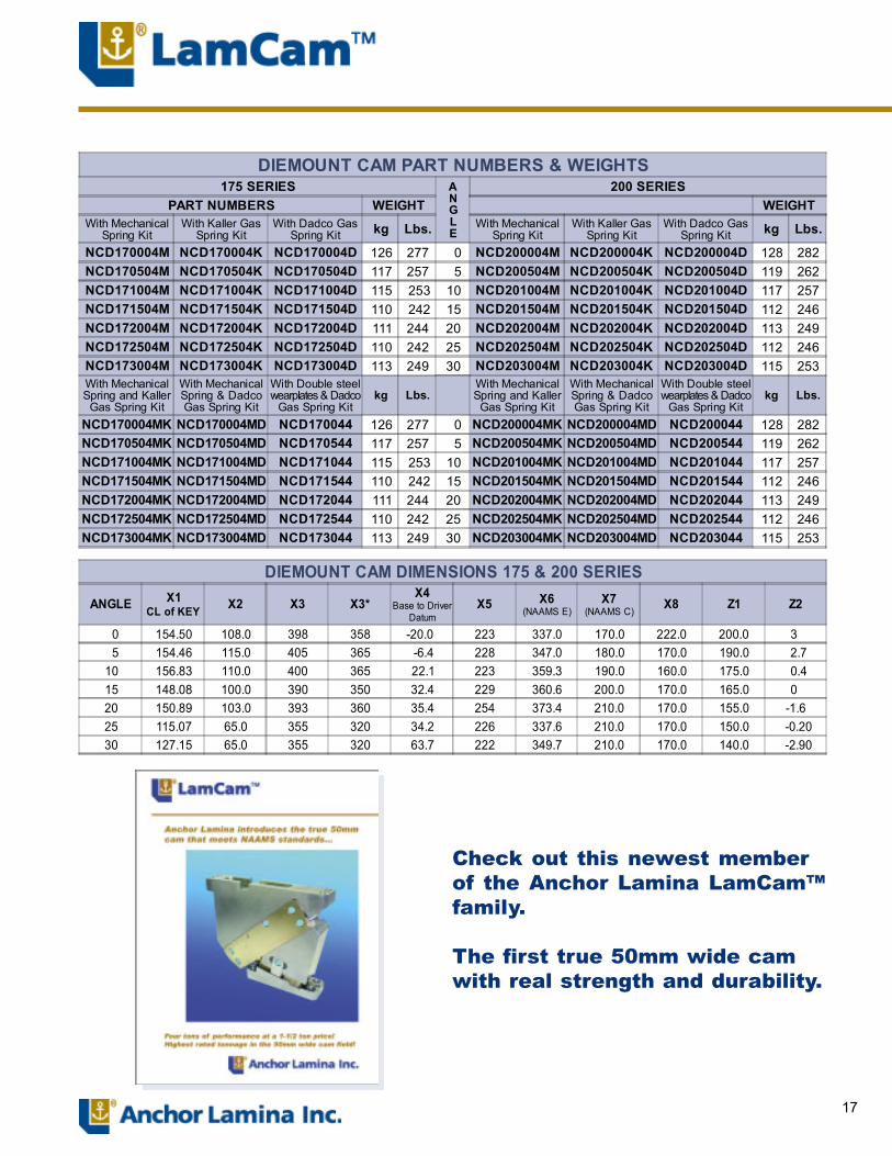
17
DIEMOUNT CAM PART NUMBERS & WEIGHTS175 SERIES A
NGLE
200 SERIESPART NUMBERS WEIGHT WEIGHT
With MechanicalSpring Kit
With Kaller GasSpring Kit
With Dadco GasSpring Kit kg Lbs. With Mechanical
Spring KitWith Kaller Gas
Spring KitWith Dadco Gas
Spring Kit kg Lbs.
NCD170004M NCD170004K NCD170004D 126 277 0 NCD200004M NCD200004K NCD200004D 128 282NCD170504M NCD170504K NCD170504D 117 257 5 NCD200504M NCD200504K NCD200504D 119 262NCD171004M NCD171004K NCD171004D 115 253 10 NCD201004M NCD201004K NCD201004D 117 257NCD171504M NCD171504K NCD171504D 110 242 15 NCD201504M NCD201504K NCD201504D 112 246NCD172004M NCD172004K NCD172004D 111 244 20 NCD202004M NCD202004K NCD202004D 113 249NCD172504M NCD172504K NCD172504D 110 242 25 NCD202504M NCD202504K NCD202504D 112 246NCD173004M NCD173004K NCD173004D 113 249 30 NCD203004M NCD203004K NCD203004D 115 253With MechanicalSpring and Kaller
Gas Spring Kit
With MechanicalSpring & DadcoGas Spring Kit
With Double steelwearplates & Dadco
Gas Spring Kitkg Lbs.
With MechanicalSpring and Kaller
Gas Spring Kit
With MechanicalSpring & DadcoGas Spring Kit
With Double steelwearplates & Dadco
Gas Spring Kitkg Lbs.
NCD170004MK NCD170004MD NCD170044 126 277 0 NCD200004MK NCD200004MD NCD200044 128 282NCD170504MK NCD170504MD NCD170544 117 257 5 NCD200504MK NCD200504MD NCD200544 119 262NCD171004MK NCD171004MD NCD171044 115 253 10 NCD201004MK NCD201004MD NCD201044 117 257NCD171504MK NCD171504MD NCD171544 110 242 15 NCD201504MK NCD201504MD NCD201544 112 246NCD172004MK NCD172004MD NCD172044 111 244 20 NCD202004MK NCD202004MD NCD202044 113 249NCD172504MK NCD172504MD NCD172544 110 242 25 NCD202504MK NCD202504MD NCD202544 112 246NCD173004MK NCD173004MD NCD173044 113 249 30 NCD203004MK NCD203004MD NCD203044 115 253
DIEMOUNT CAM DIMENSIONS 175 & 200 SERIES
ANGLE X1CL of KEY X2 X3 X3*
X4Base to Driver
DatumX5 X6
(NAAMS E)X7
(NAAMS C)X8 Z1 Z2
0 154.50 108.0 398 358 -20.0 223 337.0 170.0 222.0 200.0 3 5 154.46 115.0 405 365 -6.4 228 347.0 180.0 170.0 190.0 2.710 156.83 110.0 400 365 22.1 223 359.3 190.0 160.0 175.0 0.415 148.08 100.0 390 350 32.4 229 360.6 200.0 170.0 165.0 0 20 150.89 103.0 393 360 35.4 254 373.4 210.0 170.0 155.0 -1.625 115.07 65.0 355 320 34.2 226 337.6 210.0 170.0 150.0 -0.2030 127.15 65.0 355 320 63.7 222 349.7 210.0 170.0 140.0 -2.90
Check out this newest memberof the Anchor Lamina LamCam�family.
The first true 50mm wide camwith real strength and durability.
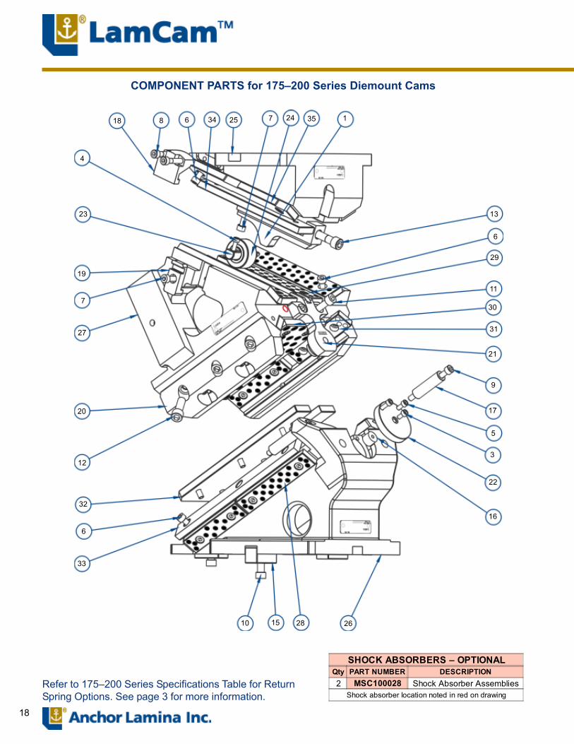
18
COMPONENT PARTS for 175�200 Series Diemount Cams
Refer to 175�200 Series Specifications Table for ReturnSpring Options. See page 3 for more information.
SHOCK ABSORBERS � OPTIONALQty PART NUMBER DESCRIPTION2 MSC100028 Shock Absorber Assemblies
Shock absorber location noted in red on drawing
18 8 6 34 25 7 24 35 1
13
6
29
11
30
31
21
20
9
17
5
3
22
16
26281510
33
6
32
12
27
7
19
23
4

19
175�200 SERIESPERFORMANCE GRAPH(Based on .04mm wear on bronze
6.05.55.04.54.03.53.02.52.01.51.00.50.0
537(60)
470(52)
403(45)
336(37)
269(30)
224(25)
157(17)
90(10)
22(2)
CYCL
ES(m
illio
ns)
WORK FORCE kN (US Tons)
(a) Actual �preload� = 0, this force is at initial contact with nitrogen spring(b) @1.6 million cycles and 0.04mm wear
Note1: For @@ in part numbers insert: (50 for 0°); (45 for 5°); (40 for 10°); (35 for 15°); (30 for 20°); (25 for 25°) and (20 for 30°).
RETURN SPRING KIT OPTIONS Recognizing that different cam applications have different requirements, Lamina offers three Return Spring Kit Options:
1 Mechanical - Employs a conventional ISO Die Spring - used in cam applications where additional strippingforce is not required.
2
Combination Mechanical/Nitrogen -This unique Lamina design employs an ISO Die Spring in series combination with a Nitrogen Spring. This return system utilizes the mechanical spring for pre- load, keeping the forces low, while providing high final loads from the nitrogen spring for stripping.
3
Nitrogen - This return system provides high return spring forces for stripping. By nature of the nitrogen spring, it also has a higher initial contact force than other return spring options. This higher contact force may result in greater wear on the cam and its accelerator system (where applicable).
175 - 200 Series SpecificationsSpring Kit Option Spring Kit Part # Pre-Load
kg (lbs.) -fFinal Loadkg (lbs.) -f
Mechanical SKC170001 64 (141) 278 (613)Combination -Mech./Nitrogen (Kaller)PreCharge to 110 Bar (1595 PSI)
SKC170002 51.3 (113) 458 (1010)
Combination -Mech./Nitrogen (Dadco)PreCharge to 110 Bar (1595 PSI)
SKC170012 51.3 (113) 458 (1010)
Nitrogen (Kaller)PreCharge to 86 Bar (1250 PSI)
SKC170003 276 (609) (a) 373 (822)
Nitrogen (Dadco)PreCharge to 69 Bar (1250 PSI)
SKC170013 276 (609) (a) 348 (767)
Tooling Allowance Protrusion - mm 175Weight - kg (lbs) 32 (70)
Rated Capacity (b) 241.8 kN : 24.2 M-Tons : 26.6 US Tons
COMPONENT PARTS FOR 175-200 SERIES DIEMOUNT CAMSITEMNO QTY Description
PARTNUMBER ITEM
NO QTY DescriptionPART
NUMBERNCDXXXX04 NCDXXXX04 NCDXXXX44*
1 1 Accelerator Block (See Note 1) 14A1230@@R 22 1 Disk Plate NCM2000083 1 Soc. Hd. Cap Screw M6x1.0x12 F010608 23 1 Roller Shaft NCM3000114 2 Soc. Hd. Cap Screw M6x1.0x16 F010609 24 1 Roller/Liner Assembly NCM300014
5 2 Soc. Hd. Cap Screw M6x1.0x20 F010610 25 1 Driver (See Note 1) NMA17@@246 50 Soc. Hd. Cap Screw M8x1.25x16 F010809 26 1 Base (See Note 1) NMD17@@137 3 Soc. Hd. Cap Screw M8x1.25x20 F010810 27 1 Slide (0° � 30°) NMD2050348 4 Soc. Hd. Cap Screw M8x1.25x40 F010814 28 2 Bronze S/L Wearplate 12x30x160mm WCC1200069 2 Soc. Hd. Cap Screw M8x1.25x90 F010823 28 2 Steel S/L Wearplate 12x30x160mm WCT12000610 3 Soc. Hd. Cap Screw M10x1.5x25 F011011 29 4 Bronze S/L Wearplate 12x38x200mm WCC12000711 2 Soc. Hd. Cap Screw M10x1.5x30 F011012 29 4 Steel S/L Wearplate 12x38x200mm WCT12000712 6 Soc. Hd. Cap Screw M12x1.75x35 F011213 30 1 Bronze S/L Wearplate 12x100x240mm WCC12000813 1 Soc. Hd. Cap Screw M12x1.75x45 F011215 30 1 Steel S/L Wearplate 12x100x240mm WCT12000815 3 NAAMS Key 25x25x50mm M082505 31 6 Bronze S/L Wearplate 12x30x125mm WCC12000916 1 Rubber Bumpers MSC100003 31 6 Steel S/L Wearplate 12x30x125mm WCT12000917 2 Lockout Spacer NCM070008 32 1 Steel Wearplate 12x100x290mm WCS12000618 2 Positive Return Bracket NCM150008 33 2 Steel Wearplate 12x30x285m WCS12000819 2 Positive Return Guideway NCM150009 34 4 Steel Wearplate 12x38x225mm WCS12000920 2 Keeper Plate NCM150010 34 2 Steel Wearplate 12x38x225mm(Notch) WCS12001421 1 Spring Return Bracket NCM200001
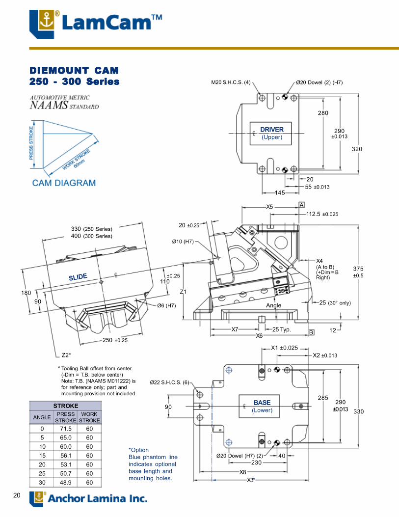
20
DIEMOUNT CAMDIEMOUNT CAMDIEMOUNT CAMDIEMOUNT CAMDIEMOUNT CAM250 - 300 Series250 - 300 Series250 - 300 Series250 - 300 Series250 - 300 Series M20 S.H.C.S. (4) Ø20 Dowel (2) (H7)
DRIVER(Upper)
280
290±0.013
320
2055 ±0.013
145
X5 A
375±0.5
X4(A to B)(+Dim = BRight)
20 ±0.25
Ø10 (H7)
112.5 ±0.025
110±0.25
Z1
25 (30° only)
12B
Angle
25 Typ.X7X6
Ø6 (H7)
X1 ±0.025X2 ±0.013
285290
±0.013
Ø22 S.H.C.S. (6)
BASE(Lower)90
Ø20 Dowel (H7) (2) 40
X8X3*
230
330
330 (250 Series)400 (300 Series)
18090
SLIDE
250 ±0.25
Z2*
Tooling Ball offset from center.(-Dim = T.B. below center)Note: T.B. (NAAMS M011222) isfor reference only; part andmounting provision not included.
*
STROKE
ANGLE PRESSSTROKE
WORKSTROKE
0 71.5 605 65.0 6010 60.0 6015 56.1 6020 53.1 6025 50.7 6030 48.9 60
*OptionBlue phantom lineindicates optionalbase length andmounting holes.
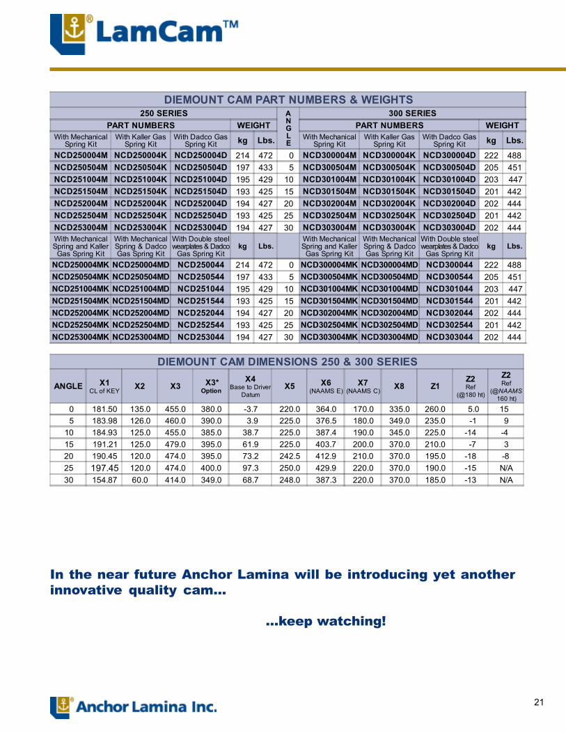
21
DIEMOUNT CAM PART NUMBERS & WEIGHTS250 SERIES A
NGLE
300 SERIESPART NUMBERS WEIGHT PART NUMBERS WEIGHT
With MechanicalSpring Kit
With Kaller GasSpring Kit
With Dadco GasSpring Kit kg Lbs. With Mechanical
Spring KitWith Kaller Gas
Spring KitWith Dadco Gas
Spring Kit kg Lbs.
NCD250004M NCD250004K NCD250004D 214 472 0 NCD300004M NCD300004K NCD300004D 222 488NCD250504M NCD250504K NCD250504D 197 433 5 NCD300504M NCD300504K NCD300504D 205 451NCD251004M NCD251004K NCD251004D 195 429 10 NCD301004M NCD301004K NCD301004D 203 447NCD251504M NCD251504K NCD251504D 193 425 15 NCD301504M NCD301504K NCD301504D 201 442NCD252004M NCD252004K NCD252004D 194 427 20 NCD302004M NCD302004K NCD302004D 202 444NCD252504M NCD252504K NCD252504D 193 425 25 NCD302504M NCD302504K NCD302504D 201 442NCD253004M NCD253004K NCD253004D 194 427 30 NCD303004M NCD303004K NCD303004D 202 444With MechanicalSpring and Kaller
Gas Spring Kit
With MechanicalSpring & DadcoGas Spring Kit
With Double steelwearplates & Dadco
Gas Spring Kitkg Lbs.
With MechanicalSpring and KallerGas Spring Kit
With MechanicalSpring & DadcoGas Spring Kit
With Double steelwearplates & Dadco
Gas Spring Kitkg Lbs.
NCD250004MK NCD250004MD NCD250044 214 472 0 NCD300004MK NCD300004MD NCD300044 222 488NCD250504MK NCD250504MD NCD250544 197 433 5 NCD300504MK NCD300504MD NCD300544 205 451NCD251004MK NCD251004MD NCD251044 195 429 10 NCD301004MK NCD301004MD NCD301044 203 447NCD251504MK NCD251504MD NCD251544 193 425 15 NCD301504MK NCD301504MD NCD301544 201 442NCD252004MK NCD252004MD NCD252044 194 427 20 NCD302004MK NCD302004MD NCD302044 202 444NCD252504MK NCD252504MD NCD252544 193 425 25 NCD302504MK NCD302504MD NCD302544 201 442NCD253004MK NCD253004MD NCD253044 194 427 30 NCD303004MK NCD303004MD NCD303044 202 444
DIEMOUNT CAM DIMENSIONS 250 & 300 SERIES
ANGLE X1CL of KEY X2 X3 X3*
Option
X4Base to Driver
DatumX5 X6
(NAAMS E)X7
(NAAMS C) X8 Z1Z2Ref
(@180 ht)
Z2Ref
(@NAAMS160 ht)
0 181.50 135.0 455.0 380.0 -3.7 220.0 364.0 170.0 335.0 260.0 5.0 15 5 183.98 126.0 460.0 390.0 3.9 225.0 376.5 180.0 349.0 235.0 -1 910 184.93 125.0 455.0 385.0 38.7 225.0 387.4 190.0 345.0 225.0 -14 -4 15 191.21 125.0 479.0 395.0 61.9 225.0 403.7 200.0 370.0 210.0 -7 320 190.45 120.0 474.0 395.0 73.2 242.5 412.9 210.0 370.0 195.0 -18 -8 25 197.45 120.0 474.0 400.0 97.3 250.0 429.9 220.0 370.0 190.0 -15 N/A30 154.87 60.0 414.0 349.0 68.7 248.0 387.3 220.0 370.0 185.0 -13 N/A
In the near future Anchor Lamina will be introducing yet anotherinnovative quality cam...
...keep watching!
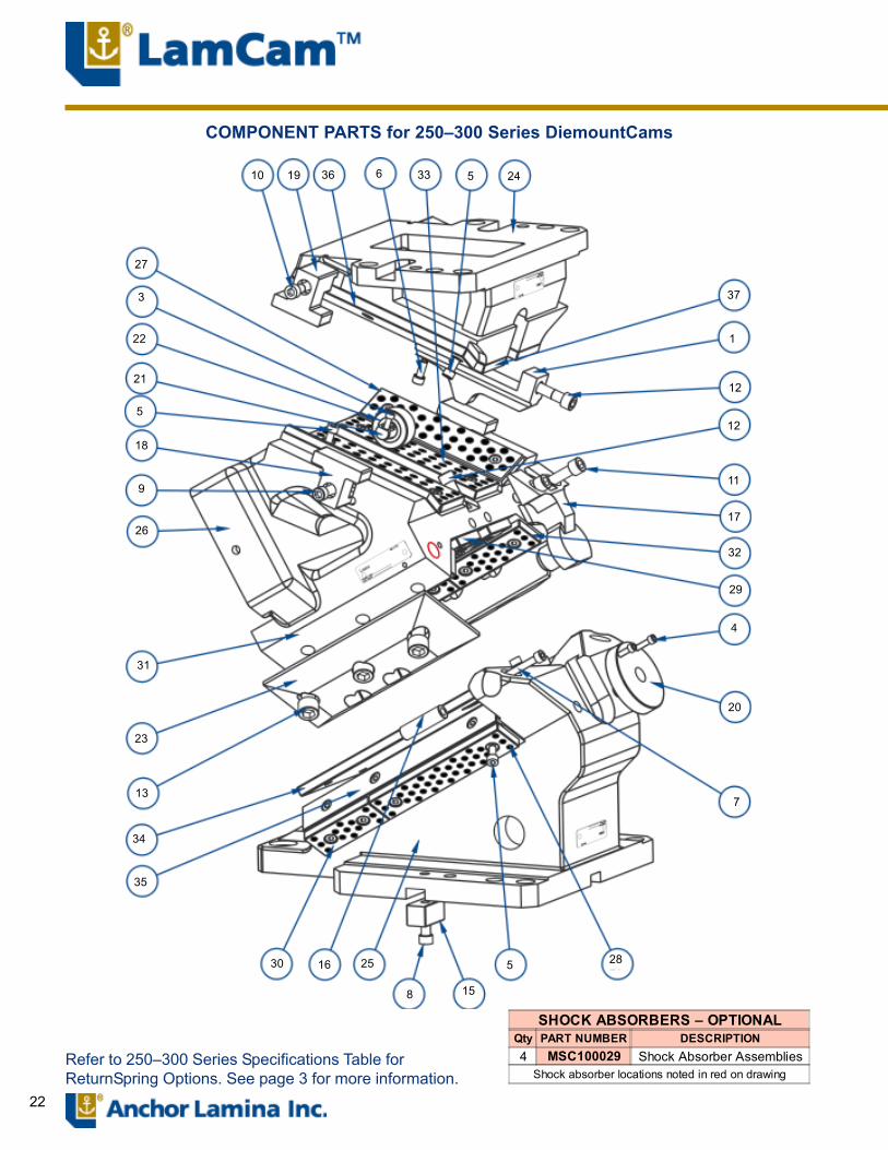
22
COMPONENT PARTS for 250�300 Series DiemountCams
Refer to 250�300 Series Specifications Table forReturnSpring Options. See page 3 for more information.
10 19 36 6 33 5 24
37
1
12
12
11
17
32
29
4
20
7
285
158
251630
35
34
13
23
31
26
9
27
3
22
21
5
18
SHOCK ABSORBERS � OPTIONALQty PART NUMBER DESCRIPTION4 MSC100029 Shock Absorber Assemblies
Shock absorber locations noted in red on drawing
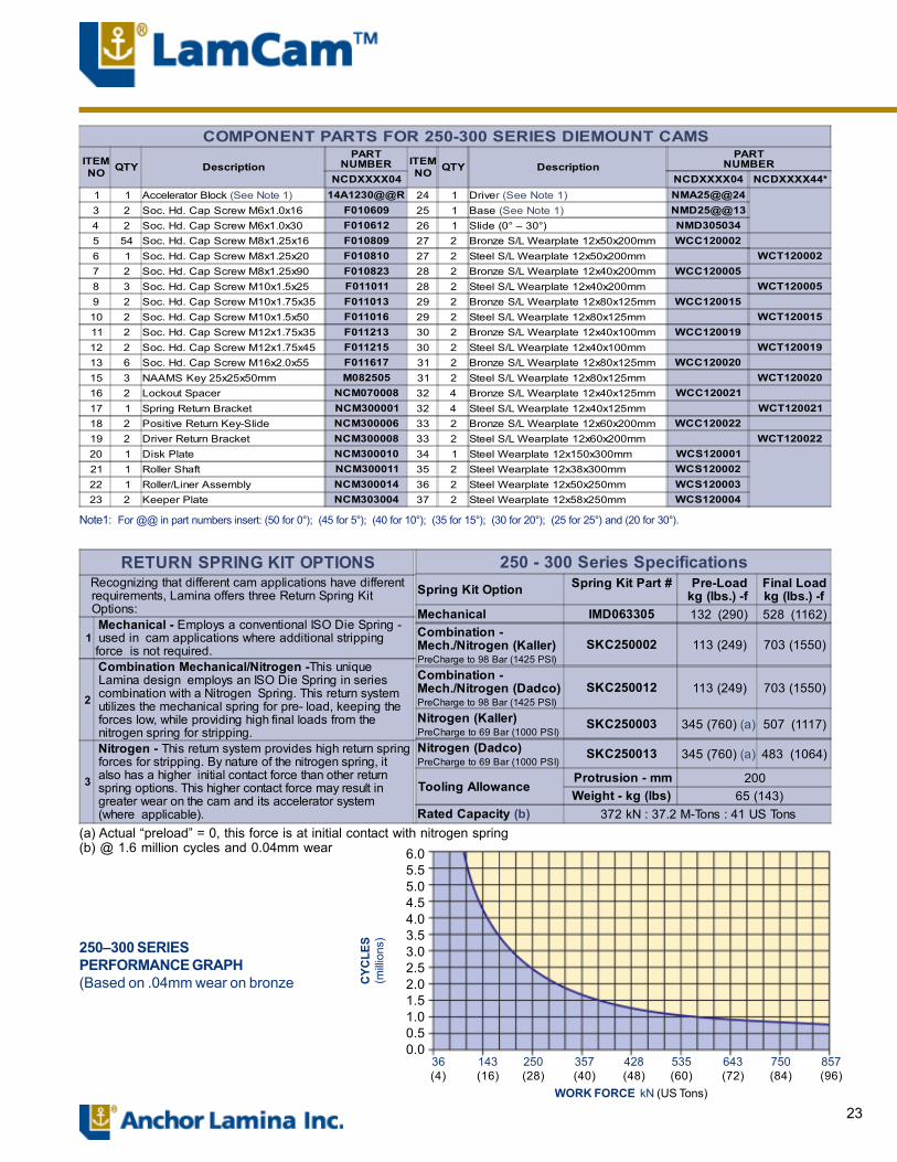
23
(a) Actual �preload� = 0, this force is at initial contact with nitrogen spring(b) @ 1.6 million cycles and 0.04mm wear
250�300 SERIESPERFORMANCE GRAPH(Based on .04mm wear on bronze
6.05.55.04.54.03.53.02.52.01.51.00.50.0
857(96)
750(84)
643(72)
535(60)
428(48)
357(40)
250(28)
143(16)
36(4)
CYC
LES
(milli
ons)
WORK FORCE kN (US Tons)
RETURN SPRING KIT OPTIONS Recognizing that different cam applications have different requirements, Lamina offers three Return Spring Kit Options:
1 Mechanical - Employs a conventional ISO Die Spring - used in cam applications where additional strippingforce is not required.
2
Combination Mechanical/Nitrogen -This unique Lamina design employs an ISO Die Spring in series combination with a Nitrogen Spring. This return system utilizes the mechanical spring for pre- load, keeping the forces low, while providing high final loads from the nitrogen spring for stripping.
3
Nitrogen - This return system provides high return spring forces for stripping. By nature of the nitrogen spring, it also has a higher initial contact force than other return spring options. This higher contact force may result in greater wear on the cam and its accelerator system (where applicable).
250 - 300 Series SpecificationsSpring Kit Option Spring Kit Part # Pre-Load
kg (lbs.) -fFinal Loadkg (lbs.) -f
Mechanical IMD063305 132 (290) 528 (1162)Combination -Mech./Nitrogen (Kaller)PreCharge to 98 Bar (1425 PSI)
SKC250002 113 (249) 703 (1550)
Combination -Mech./Nitrogen (Dadco)PreCharge to 98 Bar (1425 PSI)
SKC250012 113 (249) 703 (1550)
Nitrogen (Kaller)PreCharge to 69 Bar (1000 PSI)
SKC250003 345 (760) (a) 507 (1117)
Nitrogen (Dadco)PreCharge to 69 Bar (1000 PSI)
SKC250013 345 (760) (a) 483 (1064)
Tooling Allowance Protrusion - mm 200Weight - kg (lbs) 65 (143)
Rated Capacity (b) 372 kN : 37.2 M-Tons : 41 US Tons
Note1: For @@ in part numbers insert: (50 for 0°); (45 for 5°); (40 for 10°); (35 for 15°); (30 for 20°); (25 for 25°) and (20 for 30°).
COMPONENT PARTS FOR 250-300 SERIES DIEMOUNT CAMSITEMNO QTY Description
PARTNUMBER ITEM
NO QTY DescriptionPART
NUMBERNCDXXXX04 NCDXXXX04 NCDXXXX44*
1 1 Accelerator Block (See Note 1) 14A1230@@R 24 1 Driver (See Note 1) NMA25@@243 2 Soc. Hd. Cap Screw M6x1.0x16 F010609 25 1 Base (See Note 1) NMD25@@134 2 Soc. Hd. Cap Screw M6x1.0x30 F010612 26 1 Slide (0° � 30°) NMD3050345 54 Soc. Hd. Cap Screw M8x1.25x16 F010809 27 2 Bronze S/L Wearplate 12x50x200mm WCC1200026 1 Soc. Hd. Cap Screw M8x1.25x20 F010810 27 2 Steel S/L Wearplate 12x50x200mm WCT1200027 2 Soc. Hd. Cap Screw M8x1.25x90 F010823 28 2 Bronze S/L Wearplate 12x40x200mm WCC1200058 3 Soc. Hd. Cap Screw M10x1.5x25 F011011 28 2 Steel S/L Wearplate 12x40x200mm WCT1200059 2 Soc. Hd. Cap Screw M10x1.75x35 F011013 29 2 Bronze S/L Wearplate 12x80x125mm WCC12001510 2 Soc. Hd. Cap Screw M10x1.5x50 F011016 29 2 Steel S/L Wearplate 12x80x125mm WCT12001511 2 Soc. Hd. Cap Screw M12x1.75x35 F011213 30 2 Bronze S/L Wearplate 12x40x100mm WCC12001912 2 Soc. Hd. Cap Screw M12x1.75x45 F011215 30 2 Steel S/L Wearplate 12x40x100mm WCT12001913 6 Soc. Hd. Cap Screw M16x2.0x55 F011617 31 2 Bronze S/L Wearplate 12x80x125mm WCC12002015 3 NAAMS Key 25x25x50mm M082505 31 2 Steel S/L Wearplate 12x80x125mm WCT12002016 2 Lockout Spacer NCM070008 32 4 Bronze S/L Wearplate 12x40x125mm WCC12002117 1 Spring Return Bracket NCM300001 32 4 Steel S/L Wearplate 12x40x125mm WCT12002118 2 Positive Return Key-Slide NCM300006 33 2 Bronze S/L Wearplate 12x60x200mm WCC12002219 2 Driver Return Bracket NCM300008 33 2 Steel S/L Wearplate 12x60x200mm WCT12002220 1 Disk Plate NCM300010 34 1 Steel Wearplate 12x150x300mm WCS12000121 1 Roller Shaft NCM300011 35 2 Steel Wearplate 12x38x300mm WCS12000222 1 Roller/Liner Assembly NCM300014 36 2 Steel Wearplate 12x50x250mm WCS12000323 2 Keeper Plate NCM303004 37 2 Steel Wearplate 12x58x250mm WCS120004
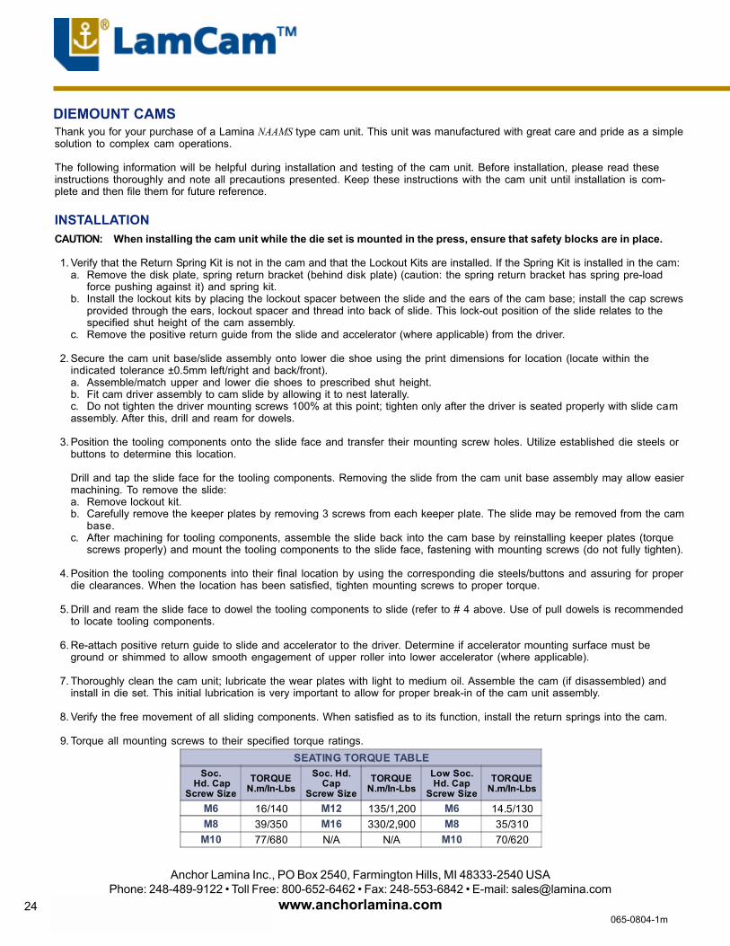
24
Thank you for your purchase of a Lamina NAAMS type cam unit. This unit was manufactured with great care and pride as a simplesolution to complex cam operations.
The following information will be helpful during installation and testing of the cam unit. Before installation, please read theseinstructions thoroughly and note all precautions presented. Keep these instructions with the cam unit until installation is com-plete and then file them for future reference.
INSTALLATIONCAUTION: When installing the cam unit while the die set is mounted in the press, ensure that safety blocks are in place.
1. Verify that the Return Spring Kit is not in the cam and that the Lockout Kits are installed. If the Spring Kit is installed in the cam:a. Remove the disk plate, spring return bracket (behind disk plate) (caution: the spring return bracket has spring pre-load
force pushing against it) and spring kit.b. Install the lockout kits by placing the lockout spacer between the slide and the ears of the cam base; install the cap screws
provided through the ears, lockout spacer and thread into back of slide. This lock-out position of the slide relates to thespecified shut height of the cam assembly.
c. Remove the positive return guide from the slide and accelerator (where applicable) from the driver.
2. Secure the cam unit base/slide assembly onto lower die shoe using the print dimensions for location (locate within theindicated tolerance ±0.5mm left/right and back/front).a. Assemble/match upper and lower die shoes to prescribed shut height.b. Fit cam driver assembly to cam slide by allowing it to nest laterally.c. Do not tighten the driver mounting screws 100% at this point; tighten only after the driver is seated properly with slide camassembly. After this, drill and ream for dowels.
3. Position the tooling components onto the slide face and transfer their mounting screw holes. Utilize established die steels orbuttons to determine this location.
Drill and tap the slide face for the tooling components. Removing the slide from the cam unit base assembly may allow easiermachining. To remove the slide:a. Remove lockout kit.b. Carefully remove the keeper plates by removing 3 screws from each keeper plate. The slide may be removed from the cam
base.c. After machining for tooling components, assemble the slide back into the cam base by reinstalling keeper plates (torque
screws properly) and mount the tooling components to the slide face, fastening with mounting screws (do not fully tighten).
4. Position the tooling components into their final location by using the corresponding die steels/buttons and assuring for properdie clearances. When the location has been satisfied, tighten mounting screws to proper torque.
5. Drill and ream the slide face to dowel the tooling components to slide (refer to # 4 above. Use of pull dowels is recommendedto locate tooling components.
6. Re-attach positive return guide to slide and accelerator to the driver. Determine if accelerator mounting surface must beground or shimmed to allow smooth engagement of upper roller into lower accelerator (where applicable).
7. Thoroughly clean the cam unit; lubricate the wear plates with light to medium oil. Assemble the cam (if disassembled) andinstall in die set. This initial lubrication is very important to allow for proper break-in of the cam unit assembly.
8. Verify the free movement of all sliding components. When satisfied as to its function, install the return springs into the cam.
9. Torque all mounting screws to their specified torque ratings.
DIEMOUNT CAMS
Anchor Lamina Inc., PO Box 2540, Farmington Hills, MI 48333-2540 USAPhone: 248-489-9122 � Toll Free: 800-652-6462 � Fax: 248-553-6842 � E-mail: [email protected]
www.anchorlamina.com065-0804-1m
SEATING TORQUE TABLESoc.
Hd. CapScrew Size
TORQUEN.m/In-Lbs
Soc. Hd.Cap
Screw SizeTORQUE
N.m/In-LbsLow Soc.Hd. Cap
Screw SizeTORQUE
N.m/In-Lbs
M6 16/140 M12 135/1,200 M6 14.5/130M8 39/350 M16 330/2,900 M8 35/310
M10 77/680 N/A N/A M10 70/620