S-38.121 Routing in Telecommunication Networks Services and service ... Call SVC Flow Internet...
32
S-38.121 / RKa, NB / Fall-04 1-1 S-38.121 Routing in Telecommunication Networks Prof. Raimo Kantola [email protected], Tel. 451 2471 Reception SE323, Wed 10-12 Lic.Sc. Nicklas Beijar [email protected], Tel. 451 5303 Reception: SE327, Fri 11-13 Assistant: Jari Huttunen and Juha Järvinen S-38.121 / RKa, NB / Fall-04 1-2 Information Course home page: http://www.netlab.hut.fi/opetus/s38121/ Newsgroup: opinnot.sahko.s-38.tietoverkkotekniikka
Transcript of S-38.121 Routing in Telecommunication Networks Services and service ... Call SVC Flow Internet...

S-38.121 / RKa, NB / Fall-04 1-1
S-38.121 Routing in Telecommunication Networks
Prof. Raimo Kantola
[email protected], Tel. 451 2471
Reception SE323, Wed 10-12
Lic.Sc. Nicklas Beijar
[email protected], Tel. 451 5303
Reception: SE327, Fri 11-13
Assistant: Jari Huttunen and Juha Järvinen
S-38.121 / RKa, NB / Fall-04 1-2
Information
Course home page:
http://www.netlab.hut.fi/opetus/s38121/
Newsgroup:
opinnot.sahko.s-38.tietoverkkotekniikka

S-38.121 / RKa, NB / Fall-04 1-3
Agenda – Fall 2004
Lectures Wed 14-16 in hall S3 and Fri 9-11 in hall S4
In English
1st half semester
Exercises Wed 8-10 in hall S4
In English
Exam 1.11.2003 13-16 in hall S4 (S1)
S-38.121 / RKa, NB / Fall-04 1-4
Agenda – Fall 2003
• 22.10 – last lecture
• 27.10 – last exercise session
• Pretty much the same topics as in 2003

S-38.121 / RKa, NB / Fall-04 1-5
Material
• A. Girard: Routing and dimensioning in circuit switched networks– Chapters 1 and 2.
• C. Huitema: Routing in the Internet– The 2nd version is recommended.– Chapters 1-6, 9-10 and 12-13.
• Specifications, RFCs, and Internet-drafts– Downloadable, links on course page
• Course handouts (via Edita) in Finnish– English versions on course homepage
S-38.121 / RKa, NB / Fall-04 1-6
Course requirements
• Goal: to understand routing on a functional level in different networks.
• Requirements: Exam + ½ of the exercises correctly solved and submitted

S-38.121 / RKa, NB / Fall-04 1-7
Exercises
• 5 exercises, 6 exercise lectures• Exam points
–4 (no exercises done) … +4 (all exercises done correctly)+ This year an extra exercise in MobileMan
• Return your answers before the following exercise lecture begins. – For example, you should submit your answer of exercise 1
before the lecture of exercise 2 begins.• You may bring your answers to the exercise class,
submit to the mailbox or send email to the assistant. – The mailbox is located in the corridor of 2nd floor near the
G-wing.
S-38.121 / RKa, NB / Fall-04 1-8
What is routing?Routing = a process of directing the user traffic from source to
destination so that the user’s service requirements are met and the constraints set by the network are taken into account.
Objectives of routing:• maximization of network performance or throughput and
minimization of the cost of the network• optimization criteria may be amount of carried traffic
(blocking probability), bandwidth, delay, jitter, reliability (loss), hop count, price.
• administrative or policy constraints and technical reasons may limit the selection.

S-38.121 / RKa, NB / Fall-04 1-9
The 1st key function of routing is collection of network state information and
information about the user traffic
• User service requirements• Location of the users• Description of network resources and use policies• Predicted or measured amount of traffic or resource
usage levelsThis information is used in route calculation andSelectionSome of this information is a´priori known or static
some is dynamic and collected on-line as needed.
S-38.121 / RKa, NB / Fall-04 1-10
Core function of routing is the generation and selection of feasible or optimal routes
• A feasible route satisfies the service requirements and constraints set by the user and the network
• An optimal route is the best based on one or many optimization criteria
• Depending on the routing algorithm may requireheavy processing. If many criteria are used, the algorithm often becomes NP-complete – i.e. not usable in practical networks.
S-38.121 / RKa, NB / Fall-04 1-11
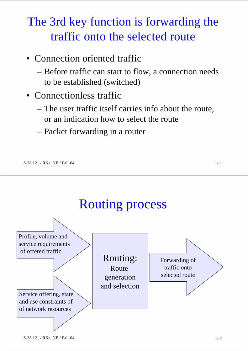
The 3rd key function is forwarding the traffic onto the selected route
• Connection oriented traffic– Before traffic can start to flow, a connection needs
to be established (switched)
• Connectionless traffic– The user traffic itself carries info about the route,
or an indication how to select the route
– Packet forwarding in a router
S-38.121 / RKa, NB / Fall-04 1-12
Forwarding oftraffic onto
selected route
Routing process
Routing:Route
generationand selection
Profile, volume andservice requirementsof offered traffic
Service offering, stateand use constraints ofof network resources

S-38.121 / RKa, NB / Fall-04 1-13
When is routing optimal?
From the user
point of view:
Network point of
view:
• Minimum probability of blocking, delay, jitter, loss or maximum bandwidth …
• Maximum network throughput. Requires short routes, while excess traffic needs to be directed to least loaded parts of the network.At the same time user service requirements need to be met.
It follows that routing is a complex optimization problem. Most times the optimum cannot be found in a closed form. Therefore, we are interested in near-optimal, heuristic approximations.
S-38.121 / RKa, NB / Fall-04 1-14
Routing is slower than switching as a mechanism of matching traffic to network resources
Slow Fast
DatagramsFlowswitching
Labelswitching
RoutingInternetmodel
Routeing PVC SVCTelephony
model
Handover
switching
S-38.121 / RKa, NB / Fall-04 1-15
Emerging inUMTS/3G
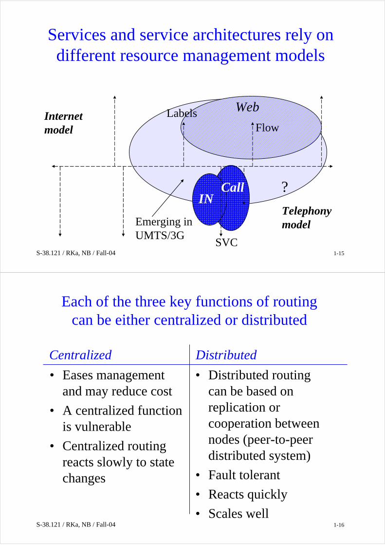
Services and service architectures rely on different resource management models
INCall
SVC
FlowLabelsInternet
model
Telephonymodel
Web
?
S-38.121 / RKa, NB / Fall-04 1-16
Each of the three key functions of routing can be either centralized or distributed
• Eases management and may reduce cost
• A centralized function is vulnerable
• Centralized routing reacts slowly to state changes
• Distributed routing can be based on replication or cooperation between nodes (peer-to-peer distributed system)
• Fault tolerant
• Reacts quickly
• Scales well
DistributedCentralized

S-38.121 / RKa, NB / Fall-04 1-17
Routing in circuit switched networks
S-38.121 / RKa, NB / Fall-04 1-18
Routing in circuit switched networks
Because a subset of functions is performed during off-line network
design, we talk about routeing (väylöitys).
Examples of routing algorithms:
• FHR - Fixed Hierarchical Routing (hierarkinen väylöitys)
• AAR - Automatic Alternate Routing (vaihtoehtoinen väylöitys)
• DAR - Dynamic Alternative Routing (dynaaminen vaihtoehtoinenväylöitys)
• DNHR - Dynamic Nonhierarchical routing (dynaaminen ei-hierarkinenväylöitys)
Lots of country-, operator- and vendor-specific variations.

S-38.121 / RKa, NB / Fall-04 1-19
The number analysis tree in an exchange connects routing to signaling information
ABC - maps to terminating exchangeABCd - shortest directory numberABCdefgh - longest directory nr
A
B
C
d
e
f
g
h
Nodes d,e,f,g,h are needed depending on nr length and switch
Buckets
The bucket file describes alternative routes/paths. Selection is based on network state.
In addition: incoming circuit groupmay affect the selection of root for analysis.Also number translations may be done before route selection.
From signaling:
S-38.121 / RKa, NB / Fall-04 1-21
Properties of number analysis in PSTN
• In originating and transit exchanges, only the leading digits need to be analyzed. “ABC…”
• The terminating exchange needs to analyze also the rest of the digits “…defgh” to find the identity of the subscriber’s physical interface
• Numbering plan can be “open ended” (variable length numbers) or be based on fixed length numbers per area code – has implications on number analysis.

S-38.121 / RKa, NB / Fall-04 1-22
Semantics of (E.164) directory numbers
• A directory number points to a subscriber or a service
• A subscriber number is at the same time the routing number as well as the “logical” directory number
• Subscriber number portability breaks this 1-1 mapping
• A service number is always only “logical” and requires a number translation to the corresponding routing number
• It must be possible to deduce the price of the call based on the dialed digits. Therefore, the allocation of directory=routing numbers is tied to geography and network topology. Plain routing numbers are tied to network topology for convenience.
S-38.121 / RKa, NB / Fall-04 1-23
Typical properties of number analysis
• Analysis takes place between Incoming Signaling and outgoing signaling. Analysis may take as input– dialed digits– incoming circuit group, origin or subscriber category (e.g.
operator)
• Analysis output may include– a set of alternative paths– translated number (e.g. for an 0800-number):
It may be necessary to repeat the analysis with the translated number as input
– all kinds of additional information that may be needed in outgoing signaling for the call
• Analysis trees are built by the operator using MML-commands based on the routing plan. (MML=man-machine language)

S-38.121 / RKa, NB / Fall-04 1-24
Example of a route description
First alternative path
Second alternativepath
Last alternativepath
Set of CG1
Set of CG3
Set of CG2
“Sets of Circuit Groups” may carry infothat is needed in signaling.
CircuitGroup
Outgoing circuits
Hunting = search of free circuit, Seizure = reservation of the circuit
The tree is traversed in some order following an algorithm until a free outgoing circuit is found. If the whole tree has been traversed, then the call is blocked.
S-38.121 / RKa, NB / Fall-04 1-25
Number portability requires a number translation prior to routing
Originatingnetwork
kauttakulku-verkkoTransit
networktuloverkkoTerminating
network
SCP(Service Control Point)
1 - Translation of the B-number to a routing nrTranslation of the routing nr of A-subscriberfor presentation and origin analysis.
1
The figure present the solution to operator to operator nr portability adopted in Finland in principle.
22
2
2 - Routing in the narrow sense

S-38.121 / RKa, NB / Fall-04 1-26
How to do routing if one or some of the networks are based on IP?
Originatingnetwork
kauttakulku-verkkoTransit
networktuloverkkoTerminating
network
SCP(Service Control Point)
Convergence of the Internet and PSTN/ISDN is happening today.
1
22
2
S-38.121 / RKa, NB / Fall-04 1-27
Service numbers require number translation
• 800-numbers, 700-numbers, 020-numbers
• Number translation can be done using IN or in an Exchange.
• Mobile numbers always require translation for a mobile terminated call – MS-ISDN → MSRN by HLR
• Management of number translation is easier in IN. An exchange is faster – (n x 100 ms vs. 1 ms).
Originatingnetwork
1
SCP(Service Control Point)

S-38.121 / RKa, NB / Fall-04 1-28
Gateway Location is the Telephony Routing prob-lem across a hybrid IP/Switched Circuit Network
+358-9-4511234
+1800-212133
+44-181-7551234
+1800-313122
Internet SCN
+358-9-657123
0800-2121
GW
GW
GW
S-38.121 / RKa, NB / Fall-04 1-29
VOIP and routing alternatives
• Gateways reside in – telephones or at customer premises – i.e. if the
destination is in the Internet use VOIP, if in PSTN use PSTN.
– Gateways reside in corporate PBX –networks.
– Gateways reside in a public network and can beaccessed from any IP address.
• two first cases are trivial, last requiresgateway location and AAA.

S-38.121 / RKa, NB / Fall-04 1-30
Network dimensioning and routing are dual tasks
• In routing, network dimensioning is given. The task is to determine how to transfer the offered traffic when network topology, link and node capacities are known.
• In dimensioning, the routing method and service level requirements are given. The task is to form a route plan and dimension the links (and nodes).
routing - väylöitysdimensioning - mitoitus
S-38.121 / RKa, NB / Fall-04 1-31
Offered or transferred traffic can bepresented in a Traffic Matrix
• Sources and destinations canbe aggregated on differentlevels
• Each element gives the amountof traffic over the measurement period.
• Is difficult to measure• When the match between the
matrix and the dimentionednetwork is far from ideal, routing may help to allocatetraffic onto the network so thatno bottlenecks are formed.
destinations
traf
fic
sour
ces

S-38.121 / RKa, NB / Fall-04 1-32
Routing systems are classified according to dynamic properties
• Does not consider the current state of the network nor changes in traffic matrix.
• Naturally takes into account the state of individual resources.– It is easy to aquire info
about resources close by.
• Dynamically reacts to changes in traffic load, traffic matrix and network state.
• Link and node failures.– It is a burden to collect
info about far away nodes
• Requires continuous processing by network nodes.
Dynamic routingStatic routing
S-38.121 / RKa, NB / Fall-04 1-33
Traditional routing in the PSTN (ISDN) is static
• Based on predicted traffic and a-prior knowledge of network topology and state
• Off-line network design produces the routing tables
• Is quite sufficient for example in the Finnish PSTN.

S-38.121 / RKa, NB / Fall-04 1-34
Adaptive routing can make more efficient use of network resources
• The collection of state information may be centralized or distributed
• It does not always pay off to react quickly to state changes, if the distribution of state changes takes too much time.
• Routing protocols are used in Internet.
• Newest PSTN routing systems collect information about call success/blocking events.
S-38.121 / RKa, NB / Fall-04 1-35
Dynamic predictive routing is an intermediate concept and is based on predicted traffic
• The use of the terms static, dynamic, and adaptiverouting varies in different sources.
• Even static routing hunts and seizures circuits – i.e. adapts to local network state.
• Dynamic (predictive) routing can for example use a set of routing tables, where each table is adapted to a time interval during a day – E.g. in USA, DHNR improved network throughput
considerably due to time difference between the east and west coasts.

S-38.121 / RKa, NB / Fall-04 1-36
The selection of route may be based on global or local information
• Efficient use of the network
• A lot of information. Real-time collection and distribution is difficult
• Vulnerable if centralized
• E.g. TINA architecture
• The solution is distributed. The nodes are autonomous.
• Scales to a network of any size.
• The goal is to find algorithms that are near optimal.
Local informationGlobal information
S-38.121 / RKa, NB / Fall-04 1-37
Traffic can be distributed to alternative paths
Ak
α k1
α k2
α k3
α kpΣp = 1 The load balancing coefficients can be
constant or be based on measurements.α k
n
In Finland needed e.g. for load distribution between alternative transitnetworks. We talk about percent-routeing.
percent-routing – prosenttiväylöitys
A very similar concept in the Internet is load balancing on a server bank based on DNS

S-38.121 / RKa, NB / Fall-04 1-38
Alternative routing is the basic family of routing methods in PSTN
B E F
A C
O D
O = Origin of the callD = Destination of the callArrows show traffic overflow or the orderof selection.
All alternate paths (routes) are describedin node routing tables. Design and mainte-nance of the tables is done off-line.
• The described alternate routes do not necessarily cover all possible routes present in the topology.
• Selection takes place using a given algorithm – the first available pathis always selected.
alternative routing – vaihtoehtoinen väylöitys
S-38.121 / RKa, NB / Fall-04 1-39
Example: Alternate routes O - D are
Primary: (o, d)Alternatives: (o, a, d)
(o, a, c, d) (o, a, e, f, d)(o, b, e, f, d)
B E F
A C
O D
X If the call has progressed to node C andthere are no free circuits on (c, d)- The call can be either blocked, or…
- The call can be returned to A(cranckback) and A may try another alternative depending on the algorithm.
S-38.121 / RKa, NB / Fall-04 1-40
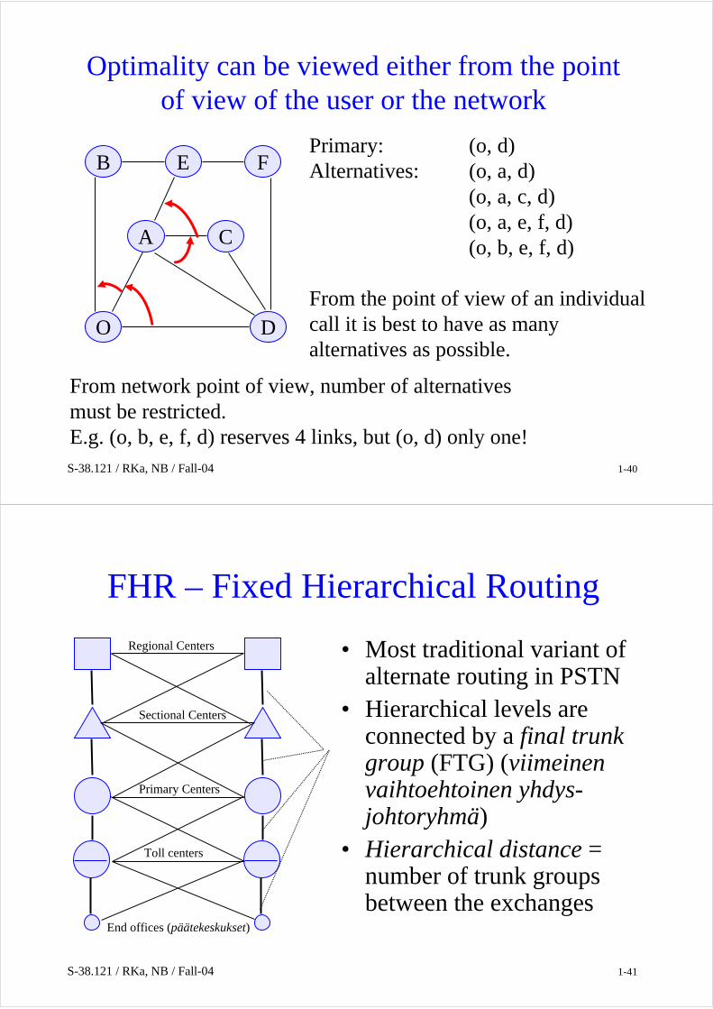
Optimality can be viewed either from the point of view of the user or the network
Primary: (o, d)Alternatives: (o, a, d)
(o, a, c, d) (o, a, e, f, d)(o, b, e, f, d)
From the point of view of an individualcall it is best to have as many alternatives as possible.
B E F
A C
O D
From network point of view, number of alternatives must be restricted.E.g. (o, b, e, f, d) reserves 4 links, but (o, d) only one!
S-38.121 / RKa, NB / Fall-04 1-41
FHR – Fixed Hierarchical Routing
• Most traditional variant of alternate routing in PSTN
• Hierarchical levels are connected by a final trunk group (FTG) (viimeinenvaihtoehtoinen yhdys-johtoryhmä)
• Hierarchical distance = number of trunk groups between the exchanges
End offices (päätekeskukset)
Toll centers
Primary Centers
Sectional Centers
Regional Centers

S-38.121 / RKa, NB / Fall-04 1-42
FHR routing algorithm1. Path selection is based only on leading
dialled digits (terminating end office). The origin of the call has no effect.
2. A node always selects the first available circuit group for an offered call among the alternatives.
3. Alternative paths are ordered according to ascending hierarchical distance measured from the current node to the terminating node.
4. Last alternative path always uses the final trunk group. If there are no free circuitson the FTG, the call is blocked.
• In different networks, variants of these basic principles can be used. End offices (päätekeskukset)
Toll centers
Primary Centers
Sectional Centers
Regional Centers
S-38.121 / RKa, NB / Fall-04 1-43
Properties of Fixed Hierarchical Routing
• Sets minimal requirements for the nodes
• Loops (call circulating in a loop) are not possible.
• Divides nodes into end offices and transit nodes. From the point of view of digital exchange technology, transit capability is almost a subset of end office capability.
• Can be shown to rather far from optimal in terms of network resource usage.
End offices (päätekeskukset)
Toll centers
Primary Centers
Sectional Centers
Regional Centers

S-38.121 / RKa, NB / Fall-04 1-44
DNHR – Dynamic Nonhierarchical Routing
• AT&T transit network, mid-1980’s – early 1990’s
• All exchanges are equal – there is no hierarchy. • A circuit group can be final for some call and
non-final for another.• Length of alternative paths is 2 hops, because
long alternative routes are problematic under overload in the network.
• Uses a series of routing tables, one is selected based on the time of the day.
• DNHR uses crankback.• Generation and optimization of routing tables
requires centralized traffic data collection Network Management
O D
C
B
A
S-38.121 / RKa, NB / Fall-04 1-45
The route tree describes the routing method
• The tree is traversed from the top to the bottom– Gives order of overflow
• In this example overflow control remains in O– OOC – Originating Office Control (lähtökeskusohjaus)
O
DA
CB O
DA
DB
Routing tree for calls from O to D: Network example:

S-38.121 / RKa, NB / Fall-04 1-46
Overflow control can move
• Overflow control moves to B, if circuit (o,b) is available.• If outgoing circuits in B are all reserved:
– blocking if there is no crankback– crankback returns the overflow control back to O
O
DC
DB
DA
A D
O
DA
CB
S-38.121 / RKa, NB / Fall-04 1-47
In Sequential Office Control (SOC), overflow control always moves
This simples tree presentation is unable to show the use of crankback.
O
C
B
A
A
C
C
O
DA
CB
D
D
D
D
D
D

S-38.121 / RKa, NB / Fall-04 1-48
An augmented tree with loss nodesdefines the routing method
D
B
C
B
NB: Link capacity to loss node is infinite.
All alternative routing methods can be describedusing such augmented route trees.
A
A
A
A
O
DA
CB
D
B
C
B*
*
A
*
A
A
*
A
S-38.121 / RKa, NB / Fall-04 1-49
Influence graph shows the presence or absence of routing loops
• If routing is based on SOC and alternative paths are longer than 2 hops, loops are possible.
• Mutual overflow (from link A to link B and from B to A) may also be undesirable.
• Influence graph can also define and analyze a partial order in a network.

S-38.121 / RKa, NB / Fall-04 1-50
Route tree with a loopD
C
B
D*
**
influence graph
D,A C,AD,C
B,D
C,B B,A
i, j Link of a route tree is mapped to a node of the influence grapth
Reservation (carry arc)
Overflow arc
Graph gives all possible paths, selected routedepends on the reservation state of the links
O
DA
CB
A
A
A
A
S-38.121 / RKa, NB / Fall-04 1-51
Influence graph can be presented in an algebraic form
σ(i, j) – For trunk group i, and calls destined for j, indicates number of the trunk group to which a blocked call will overflow.
ρ(i, j) – For trunk group i, and calls destined for j, indicates number of the trunk group to which calls that are carried on iwill be offered.
• Existence of a loop in the influence graph is equivalent with the existence of a routing loop in the network design.
• Lots of well known standard algorithms for graphs exist Loops are easy to find.

S-38.121 / RKa, NB / Fall-04 1-52
Mutual overflows are revealed by superposition of influence graphs
If there are no loops, a partial order exists in the network. Dimensioning
and modelling of the routing are simplified in case a partial order exists.
D,A D,B B,A
D,C C,A
C,B
SOC
D,A D,B B,A
D,C C,A
C,B
E
DA
CB
E
DA
CB
S-38.121 / RKa, NB / Fall-04 1-53
Adaptive routing
• Computer controlled exchanges can use a more varied set of input data for route calculation than just dialed digits.
• Alternate Routing allocates traffic to a small set of alternative paths in a predetermined order.
• Adaptive routing allocates traffic to a possible large set of alternative paths without a pre-determined order.
• Value function is calculated for the alternatives determining the selection of the path among all alternatives.
• Variations are based on the type of the value function, way of collecting input data for the value function etc.
S-38.121 / RKa, NB / Fall-04 1-54
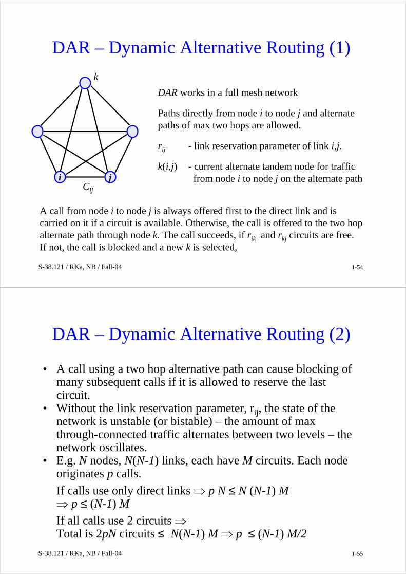
DAR – Dynamic Alternative Routing (1)
i jCij
DAR works in a full mesh network
Paths directly from node i to node j and alternate paths of max two hops are allowed.
rij - link reservation parameter of link i,j.
k(i,j) - current alternate tandem node for trafficfrom node i to node j on the alternate path
A call from node i to node j is always offered first to the direct link and iscarried on it if a circuit is available. Otherwise, the call is offered to the two hopalternate path through node k. The call succeeds, if rik and rkj circuits are free. If not, the call is blocked and a new k is selected,
k
S-38.121 / RKa, NB / Fall-04 1-55
DAR – Dynamic Alternative Routing (2)
• A call using a two hop alternative path can cause blocking of many subsequent calls if it is allowed to reserve the last circuit.
• Without the link reservation parameter, rij, the state of the network is unstable (or bistable) – the amount of max through-connected traffic alternates between two levels – the network oscillates.
• E.g. N nodes, N(N-1) links, each have M circuits. Each node originates p calls.
If calls use only direct links ⇒ p N ≤ N (N-1) M⇒ p ≤ (N-1) MIf all calls use 2 circuits ⇒Total is 2pN circuits ≤ N(N-1) M ⇒ p ≤ (N-1) M/2

S-38.121 / RKa, NB / Fall-04 1-56
DAR – Dynamic Alternative Routing (3)
• Even on high capacity links r is a small value.• It is even sufficient that r ≠ 0 is defined only for the first link
on the alternative paths.• If one call is allowed to try more than one alternative two hop
path, the value of r must be increased.
S-38.121 / RKa, NB / Fall-04 1-57
DAR variants
• Current tandem node is switched when the last allowed circuit is reserved on the alternative path.
• Some alternative nodes may be better than others →the selection of a new tandem node can be weighted to favor good nodes instead of being just random.
• If a lot of traffic is carried on the alternative route, it can be distributed to several current alternative paths each of which is switched independently.

S-38.121 / RKa, NB / Fall-04 1-58
BT implementation of DAR (1)
Local node The local exchanges that have the same parent (DMSU)form a Cluster
DMSU
Access link
Core link
Each node has two parents:(home and security) - dualparenting.
• Always two direct routes from the originating DMSU.
• Alternative path tandem DMSU has two paths to the destination.
• Alternative routing on the access links.
transit networkaccess network
Digital Main Switching Unit (DMSU) – a trunk exchange primarily used for connecting long distance calls.
S-38.121 / RKa, NB / Fall-04 1-59
BT implementation of DAR (2)
DMSU
Access link
Core link
BT has more than 60 DMSU’s.
Possibilities:
• Incoming and outgoing traffic on Access links can go primarily thrudifferent parents.
• Extension of the Scenario to multi-parent network.
• Nrof parents per access node can vary.
• Nrof alternative tandem nodes is N - 3.Last Chance priority• Incoming traffic that has reached the destination parent has only one chance to succeed.• Therefore, it makes sense to define a trunk reservation parameter for Access links
so that outgoing traffic is not allowed to reserve the last circuit on the primary accesslink for terminating traffic.

S-38.121 / RKa, NB / Fall-04 1-60
Adaptive routing in a (international) partial mesh network
Alternatives:• ISC-to-country link reservation status is
passed to DMSU which offers outgoing traffic to least loaded ISC – needs additional signaling.
• Proportionate routing (kuormanjako) –needs reliable predictions of traffic
• Crankback from ISC if int-links reserved –in overload the processing load in nodes grows quickly: call is transferred back and forth from one ISC to another + Additional capacity from DMSU to ISC can degrade the overall performance.
• DAR with fixed primary-ISC – problem is how to allocate the primary roles to ISC’s.
• DAR to one primary ISC, switch to alternative ISC if a call is blocked – one call has only one chance to succeed. This turns out to be the best algorithm!
DMSU
ISC
ISC
ISC
ISC USA
France
Japan
Bangladesh
S-38.121 / RKa, NB / Fall-04 1-61
Comparison of DAR variants
Alternative algorithms:
1. Outgoing traffic always offered to parent i and terminating traffic to parent j. In the full mesh transit network direct and all two alternative paths are allowed (single parenting) -high blocking probability.
2. All four direct routes are allowed, least loaded is chosen (LLR-least loaded routing).
NB: This requires distribution of the reservation state information! Performance approaches to theoretical optimum.
3. We are interested in finding a method with performance approaching to LLR, but such that it is easy to implement
⇒ sticky principle and last chance priority.
DMSU
Access link
Core link

S-38.121 / RKa, NB / Fall-04 1-62
Sticky principle retains a path if a call succeeds and skips the path if blocking occurs
1. Primary parent of node i towards j is it
2. Primary destination parent of tandem it
towards j is js
3. If call succeeds thru it js, primary roles are retained.
4. If blocking occurs thru it js, call is offered to it j1-s, if success, it adopts j1-s as the primary choice towards j.
5. If 4 fails, call is blocked and i adopts i1-t
as the primary choice towards j.
i j
it js
i1-t j1-s
S-38.121 / RKa, NB / Fall-04 1-63
General sticky principle combines sticky learning with last chance priority
Call from i to j
Primary parentfor (i, j ) is it
Primary pathfor (it , j ) is s
>ris,jt free circuits on (it, js)
>0 free circuits on (it, j1-s)
No
Offer callto (it, js)
Yes
Primary pathfor (it , j ) is 1-s
Yes Offer callto (it, j1-s)
Primary parentfor (i, j ) is i1-t
Call is blocked
No

S-38.121 / RKa, NB / Fall-04 1-64
RCAR - Residual Capacity Adaptive Routing is used in Canada
• Implementation name: DCR – dynamic call routing/Telecom Canada
• Info about outgoing circuit reservation status, number of blocked calls and CPU load is collected each 10s to a centralized network management center. The center calculates and downloads new routing tables for I and T switching nodes.
• The idea is to choose the path with most free circuits.
• Improves network performance significantly.
• Adapts quickly to unusual traffic patters and to link and node failures.
• Benefits relate to time difference between coasts.
• Vulnerable to failure of management center. Falls back to FHR model, if the center stops.
T
T
T
I I
X X
S-38.121 / RKa, NB / Fall-04 1-65
Summary of routing in SCN• Static routing is most common in PSTN• Alternative routing is easy since route pin-down is natural:
existing calls stay on their original route when fresh callattempts are placed on an alternative path – this is differentfrom the Internet in which a change in routing immediatelyaffects all packets towards the destination
• Dynamic routing with local information often achieves as lowblocking as least loaded routing that needs global knowledge.– may require careful tuning to achieve stability
• Dynamic Non-hierarchical routing in AT&T’s network led to the invention of TMN – Telecommunications Management Network
• We have learned methods to describe the routing algorithm in an SCN accurately.