RZ LioN-Link Brochure GB:LioN-Link - Belden...LioN-Link offers a complete range of connection...
64
Optimization of Field Wiring Through the Utilization of a Modular IP 67 Fieldbus Solution LioN-Link The Modular, Fieldbus Independent I/ O System
Transcript of RZ LioN-Link Brochure GB:LioN-Link - Belden...LioN-Link offers a complete range of connection...

Optimization of FieldWiring Through the Utilization of a Modular IP 67 Fieldbus Solution
LioN-LinkThe Modular, Fieldbus Independent I/O System
Lio
N-L
ink – T
he M
odula
r, Fie
ldbus In
dependent I/O
Syste
m
GLOBAL LOCATIONS
CONTACT FOR LUMBERGAUTOMATIONTM BRAND
Im Gewerbepark 258579 SchalksmühleGermanyPhone: +49-2355-5044-000Fax: [email protected]
CONTACT FORHIRSCHMANNTM BRAND
Stuttgarter Straße 45-5172654 NeckartenzlingenGermanyPhone: +49-7127-14-0Fax: [email protected]
CONTACT FOR BELDEN® BRAND
Edisonstraat 95928 PG VenloThe NetherlandsPhone: +31-77-3878-555Fax: [email protected]
©Copyright 2010, Belden Inc.
Printed in Germany
DS 280 720-884 04.2010
For worldwide sales and technical support, visit us at: www.lumberg-automation.com
www.beldensolutions.com
RZ_LioN-Link_Brochure_Umschlag-komplett_GB 12.04.2010 13:01 Uhr Seite 1
2
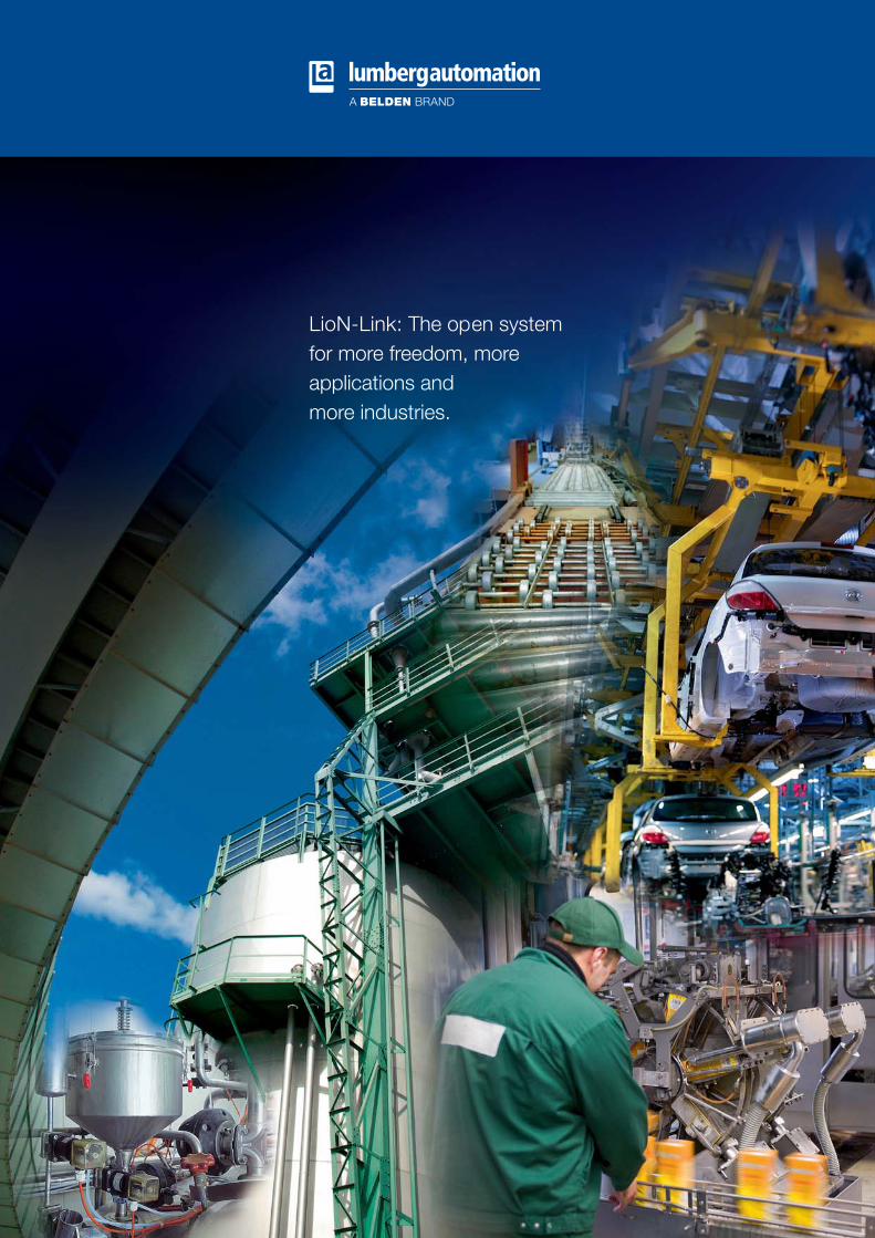
LioN-Link: The open system for more freedom, more applications and more industries.
RZ_LioN-Link_Brochure_GB:LioN-Link 12.04.2010 12:55 Uhr Seite 2

3
About Belden®
Effective Signal Transmission Solutions
At Belden, our customers and their require-ments are our top priority. All of our leadingbrands – Belden®, Hirschmann™ and LumbergAutomation™ – enjoy an excellent reputationfor quality and added value in their respectivecore markets.
The combination of proven experience and innovation behind these brands has madeBelden the largest provider of an integratedrange of wired and wireless systems.
Belden offers an extensive product range, including cables, connectors, I/O modules andnetworking components. Thanks to cooperationbetween our brands, we are able to providecomplete signal transmission solutions from a single source with worldwide market accessand delivery.
Products, People and Performance
Our extensive product range means we can deliver complete solutions backed up by comprehensive technical services. We can provide consultation, development, design and training to meet your standards and expectations.
We work with qualified partners and loca l experts to ensure that our world class productsintegrate seamlessly into your applications,helping you to achieve the best possible performance and added value.
Connectivity Solutions for AutomationTechnology
The Lumberg Automation™ and Hirschmann™brands are synonymous with high quality connectors and innovative wiring solutions for use in virtually all areas of automation. Our customers use Lumberg Automation™ andHirschmann™ products in machine building andplant engineering, building wiring installationand photovoltaic applications.
Contents Page
From the Solution of a Problem to the LioN-Link Standard 4–6
LioN-Link Wiring 7–8
Effective Connectivity Solutions 9–12
Advantages of the LioN-Link System 13
Technical Data 14–57
Wiring Accessories BusHead and I/O Modules 58–60
LioN-Link Configurator 61
Index 62
General Technical Information 63
The product portfolio for these two brands comprises a wide range of connectors for sensors and actuators, single and double endedcordsets as well as distribution systems and I/O modules for connection to fieldbus andEthernet networks.
Thanks to many years of close cooperationwith system integrators and end customers in the machine building market, Lumberg Automation™ is able to deliver customized solutions using a wide range of products de-signed according to the latest market standardsand leading edge technologies.
Lumberg Automation™ and Hirschmann™ pro-ducts are renowned for their high mechanicaland electrical loading capacity, excellentchemical resistance and ease of use.
Together, Lumberg Automation™ andHirschmann™ are among Europe’s leading suppliers of connectors and wiring solutionsfor automation technology.
RZ_LioN-Link_Brochure_GB:LioN-Link 12.04.2010 12:55 Uhr Seite 3

4
From the Solution of a Problem to the LioN-Link Standard
Lumberg Automation™offers effective connectivity solutionsfor demanding applications at fieldlevel.
The development and manufacturing expertise of Lumberg AutomationTM is evident not only in the extensive and continuously expanding range of catalogproducts, but also in the company’s individual and flexible customer solutions.
The LioN-Link decentralized I/O fieldbus system, which can be used to create line topologies of up to 100 meters in length, consists of bus coupler modules, which function as the interfaceto higher level fieldbuses such as Profibus, CANopen®, DeviceNet or ProfiNet, and protocol independent I/O modules.
Engineers therefore only have to make minimal changes to the hardware if their end customersuse different transmission protocols for the connection of systems to their communications network. Only the BusHead requires an address setting, the fieldbus independent I/O modulesare commissioned without module addressing. Furthermore, a terminator is not required in either link line. Both features contribute to protection against manipulation.
The bus coupler and I/O modules, whose connections are designed for M12 or M8 connectors,are easy to install and commission thanks to the plug and play principle. They also offer comprehensive diagnostics options, meet the requirements for degree of protection IP 67 andhave high vibration and shock resistance. Lumberg Automation™ fieldbus systems are thus idealfor use in extreme environments.
The LioN-Link I/O fieldbus system not only facilitates secure data communication, but also con-tributes to the efficient operation of machines and systems, however the field wiring may look.With LioN-Link it is always possible to implement customized solutions. The system offers a highdegree of flexibility, which is very useful in the planning phase and during subsequent retro-fitting or conversion. It also helps to reduce power consumption.
LioN-Link offers a complete range of connection components at field level. These include components for the control of electric drives, the networking of intelligent sensors and actuators (e.g. proximity switches, motor starters and valves), straightforward retro-fitting/conversion of machines, safety applications and decentralized power supplies.
CANopen® is a registered Community Trademark of CAN in Automation e.V.
RZ_LioN-Link_Brochure_GB:LioN-Link 12.04.2010 12:55 Uhr Seite 4

5
RZ_LioN-Link_Brochure_GB:LioN-Link 12.04.2010 12:55 Uhr Seite 5

6
Close to a Process
All LioN-Link modules are compliant with the IP 67 protection standard and are vibration andshock proof, which means that they can be used close to the process directly at field level.
Thanks to an innovative techno logical dev elop ment, the complete production process can becarried out without encapsulation, making LioN-Link modules ideal for use in the smallest handling robots due to their low weight.
Universal I/O Functionality
No matter what the final design of your field wiring may be , a single I/O module is all you needto realize a whole range of different configu ra tions. Each signal pin can be used as both an inputand an output – without any additional configuration.
This gives you maximum flexibility when it comes to planning, making changes during commissioning and when retrofitting at a later date.
Quick, Fast and Easy Installation
Thanks to the staggered arrangement of the ports and the opti mization of the distance betweenthe ports, it is easy to screw on both molded and field attachable conn ectors. The LioN-Linkmodules are designed for both rear and lateral installation and can even be attached directly to profile rails.
Color Coding
Thanks to the color coding of the individualplug conn ections, the function of the plug-inposition can be recognized directly at firstglance (fieldbus, link, power supply or I/O) .This allows you to quickly attach the connection cable you need .
Color Function
Purple Profibus bus connection
Black CANopen®/DeviceNet bus connection
Green ProfiNet
Orange LioN-Link connection
Grey Power supply connection
RZ_LioN-Link_Brochure_GB:LioN-Link 12.04.2010 12:56 Uhr Seite 6

7
Easy Wiring with Standard Connectors
Thanks to the utilization of standard components you are also assured of uninterrupted procurement and individual part inventory availability . All of the connectors and cables necessary for the LioN-Link system can be acquired anywhere in the world .
Standard M12 connectors are used exclusively for fieldbus and link, standard M8/M12 connectors for the coupling of the sensors and actuators and standard M12/7/8" connectors for the power supply.
Advantages
• Reduced variety of part types• Easy worldwide procurement
Link Wiring with:
Standard actuator/sensor cordsets,single and double ended
... or
Field attachable M12 connectors
CAN/DeviceNet Thin cables
... or
RZ_LioN-Link_Brochure_GB:LioN-Link 12.04.2010 12:56 Uhr Seite 7

8
Bus Connection
Bus
Hea
dI/
O M
odul
eI/
O M
odul
eI/
O M
odul
e
Line 1Line 2
LioN
-Lin
k C
onne
ctio
n
out
out
in in
out out
in in
out out
in in
100 m
Line 1Line 2
out
out
in in
out out
in in
out out
in in
in
out
in
out
(Profibus extension at 12 MBit = max.100 m!)
LioN-Link Wiring, Ideal for Large I/O Expansion
The LioN-Link 0941 UNC 601/…M powermodule is used for decentralized powersupply for I/O modules. It has four ports,two potential circuits and a 10 m leadwith a conductor gauge of 5x1 mm2. This provides for bridging distances of up to 25 m without voltage loss as well as for configuring separate potentialgroups each with their own fuses.
Effective Connectivity Solutionswith the LioN-Link Power Module
RZ_LioN-Link_Brochure_GB:LioN-Link 12.04.2010 12:56 Uhr Seite 8

9
Effective Connectivity Solutions with LioN-Link Support for I/O-Link: 0940 PSL 602/0940 ESL 601 and 0942 UEM 620
A strong Connection with LioN-Link and I/O-Link
From a user perspective, the issue of the wiringof analog signals in machines and systems has always been problematic due to the use of shielded connection cables. Although theprocessability of the various components such as cables and connectors has improvedsignificantly in recent years, the assembly of ashielded cable still remains quite an elaborateprocedure.
Lumberg Automation™ offers an effective solution to this problem. Thanks to the inte-gration of an I/O-Link interface into the LioN-Link system in conjunction with I/O-Linkcapable sensors, users can now utilize standardwiring components such as unshielded M12connection cables to set up the connection.
The 0942 UEM 620 I/O-Link master moduleprovides point-to-point connections for theintelligent sensors and actuators by means ofthe I/O-Link protocol. The four ports can beconfigured as digital I/Os or for communica-tions mode. The module is wired with three-conductor, unshielded standard cords that canbe up to 20 m in length. The PROFIBUS buscoupler module allows users to connect up to six master modules. In combination with a PROFINET bus coupler module from the LioN-Link family, the I/O-Link master modulecan also be used in Ethernet networks.
LioN-Link ProfiNet BusHead
Lumberg Automation™ has developed a newbus coupler with PROFINET interface for themodular, decentralized LioN-Link system. Thisbus coupler has an integrated switch, which allows wiring of the PROFINET network in theline structure familiar from PROFIBUS networks.
There is also an integrated web server, which canbe accessed via a standard TCP/ IP connection.With this connection, various information canbe retrieved and settings can be adjusted using astandard web browser. In addition to retrievingdevice information, it is also possible to set IPaddresses directly. Diagnostic data for the con-nected LioN-Link I/O modules is also displayed,as is status information. The integration of amonitoring function facilitates the checking of the sensors and actuators connected to theI/O modules. This is facilitated by the graphicalrepresentation of the LioN-Link system structurein the web browser.
These useful tools make the system much easier to use, particularly with regard to commissioning, installation and maintenance.
Effective Connectivity Solutions with LioN-Link. Outputs for Safety Critical Applications with 0942 UEM 612
The 0942 UEM 612 I/O module is suitable forintrinsically safe actuator control or reliable emergency power off functions. It has four digital outputs for increased output currentlimiting of 2 A per line and a maximum totalof 6 A. The module has outputs that are designed for safety critical applications up toPerformance Level D of the new machinery directive.
RZ_LioN-Link_Brochure_GB:LioN-Link 12.04.2010 12:56 Uhr Seite 9

10
Effective Connectivity Solutions with LioN-LinkShadow Mode: 0940 PSL 603 and 0942 UEM 620
Customized Solutions for High Flexibility
The 0940 PSL 603 bus coupler module permits the integration of up to 30 shadow modules in a Profibus network. Serving as inactive secondarycomponents, these modules each provide eight digital I/O connections.
They can be activated by means of a hot plug function without compromising the higher levelProfibus communication. In this way, systems can be retrofitted or upgraded when in operation andwithout the need for additional hardware.
The Lumberg Automation™ shadow module supportsthe management of just one, dynamically adaptable,but downwards compatible control software overthe entire life cycle or plant manufacture cycle. Retaining the created hardware configuration andcontrol program, it is possible to configure any assembly line individually in accordance with theequipment level.
Partial assembly of the sub bus system (due to differ-ent equipment levels) does not lead to a bus error.I/O modules that exist logically, but not physically,are ignored by the BusHead and no error message is generated.
This requires a configuration file, in which the com-missioning engineer specifies the available equip-ment. When control is activated, this configurationis transferred in the form of a binary pattern to theBusHead, which analyzes it for comparison with theoriginal configuration and applies the differences as the current status. If a module then fails duringoperation, this failure is identified according to theprevious LioN-Link standard and signaled as a buserror. Only universal modules of type 0942 UEM 670(8xM8) are used in the I/O area. The I/O memoryarea is always reserved for a complete assembly, irrespective of the respective equipment level.
The I/O modules can also be parameterized as dedicated input or output modules, whereby the I/O address space is not affected and is nevertheless reserved (shadow mode).
I/O
Mod
ule
I/O
Mod
ule
�
�� �
Bus Connection
out
in
in
out
out
in
out
in
out
out
in
out
in
Bus
Hea
dI/
O M
odul
e
out
out
in
Line 1
Line 2
RZ_LioN-Link_Brochure_GB:LioN-Link 12.04.2010 12:56 Uhr Seite 10

11
Effective Connectivity Solutions with LioN-LinkTool Changer Mode: 0940 PSL 603
The Fast System for Increasing Productivity and Efficiency
With the 0940 PSL 603 bus coupler module,Lumberg Automation™ has upgraded the LioN-Link product family for other areas of application and provides the options of quickand simple tool change.
The Lumberg Automation™ LioN-Link systemcan be connected or disconnected during operating time without affecting the super -imposed Profibus strand. Bus errors are thusavoided. Areas of application in this case aretool couplings on automatic assembly machines or robot systems.
The LioN-Link system from Lumberg Automation™saves both time and money and thus a perma-nent increase in productivity.
Bus Connection
Bus
Hea
dI/
O M
odul
eI/
O M
odul
e
�
out
out
in
out
in
�
Media Coupling
Media Coupling
Pluggable ToolCoupling
out
in
a) b)
out
out
outI/
O M
odul
e
�out
in
in
Line 1
Line 2
in
Media Coupling
out
in
out
�outin
in
RZ_LioN-Link_Brochure_GB:LioN-Link 12.04.2010 12:56 Uhr Seite 11

12
Effective Connectivity Solutions with LioN-Link Motion Drive Control: 0940 PSL 602 and 0942 UEM 620
Direct current drives are increasingly beingutilized in many areas of automation techno -logy for a wide variety of tasks. The advantagesare obvious – small, compact, energy efficientdrives with a high degree of performance efficiency. From a cost perspective, thesedrives often represent a good alternative toother solutions. However, integration into auniform bus concept is often difficult. Thecomponents needed for this purpose are notreadily available.
This gap has now been filled by a new modulein the LioN-Link family from Lumberg Automation™ – Motion Drive Control. This sys-tem makes it possible to set up the connectionbetween drives and the various bus systems.
The new module is equipped with four outletsthat can be configured for brushless (EC) motors as well as for brush loaded (DC) motorsand all types of digital actuators such as directcurrent motors or valves. Some of the specialfeatures of the LioN-Link Motion module include dynamic rpm control, parameterizablestart/stop ramps for EC motors and an inte-grated brake resistance for DC motors.
These parameters can also be modified at anytime during operation when a suitable controlsystem is utilized. The demand for increaseddynamics and maximum possible flexibility hasbeen met as a result. The module also provideseight digital inputs. The wiring complexity is thus minimized for the sensor system allocated.
The good diagnostics capability that is a feature of the entire LioN-Link system is ofcourse included with the Motion Drive Controldistribution box. As a result, motor and sensorfaults can be diagnosed according to channel,both visually and in the form of software messages. And of course we have also satisfiedstringent requirements with respect to thetype of protective system and resistance to vibrations and shocks, as is the case with theentire LioN-Link system.
Key Features
• Networking across multiple segments
• Each conveying zone is divided into segments. Multiple rollers are combined ineach segment, i.e. communication with thebus system beyond this segment is possible
• Utilization of standard sensors
• Reduced wiring complexity through the use of connectors
• Only one 24 V network, no AC network andno pneumatic components required
• Energy saving (savings potential can be realized with effective motor control, as the motors are only started when they areneeded)
• Dynamic rpm control (acceleration and deceleration) allows soft startup and braking of the rollers
• Comprehensive diagnostics options
• Up to 10,000 motors with one fieldbus master
• LioN-Link: a compact system for I/O andmotor control
Advantages for System Users
• Reduced operating costs, e.g. energy savingor control optimized utilization of rollers
• Minimal investment costs, good price/performance ratio thanks to an optimumcontrol concept
• Low maintenance costs thanks to standard-ized components. Rapid replacement throughutilization of M8/M12 connectors
Advantages for Conveyor Manufacturers
• Activation via Profibus with diagnosticfunctionality and fault management
• Easy commissioning and installation thanksto minimal wiring complexity with M8/M12connectors
• Variable motor roller running characteristicswith acceleration and deceleration profiles,which can be optimized specifically for theproduct to be conveyed
• Interface to other fieldbus systems and Ethernet technologies
Advantages for System Integrators andMachine Builders
• Very good diagnostics capability
• Low servicing costs loss thanks to durabilityand reliability
• LioN-Link: one system for all inputs andoutputs plus motor control
RZ_LioN-Link_Brochure_GB:LioN-Link 12.04.2010 12:56 Uhr Seite 12

13
Advantages of the LioN-Link System at a Glance
Per BusHead:
• 15 devices per line
• 100 m extension per line
• Unlimited distance between two devices up to maximum extension
• Cycle time approx. 2 ms
• No terminators
• Wiring with standard components:- Reduced variety of part types and costs - Easy purchasing worldwide (manufacturer independent)
• Input modules are supplied using the LioN-Link, no additional connection cable required
• Plug and play commissioning without special utilities
• Diagnostics for periphery faults and bus errors
• Visual differentiation of connections by means of color coding
• Low weight, ideal for small handling robots
• No module addressing and no terminator required
• Universal modules are configuration free
• Supply of safety critical actuators can take place decentrally in the field, no individual wiring
• Expansion of the PROFIBUS network WITHOUT repeaters and retaining the max. baud rate
RZ_LioN-Link_Brochure_GB:LioN-Link 12.04.2010 12:56 Uhr Seite 13

14
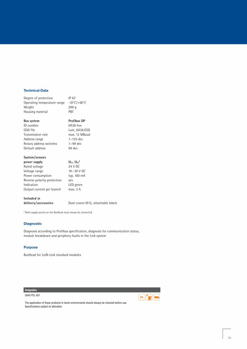
0940 PSL 601
LioN-Link BusHead Profibus-Slave
LioN-Link BusHead IP 67 bus coupler modulefor the connection between the higher levelfieldbus and the fieldbus independent I/Omodules, with M12 bus connection, rotaryswitches for addressing, M12 LioN-Linkconnection, M12 power supply connection
Diagnostic Indication
LED Indication Condition
I /O Line 1, I/O Line 2 red wrong configuration/module exchangedgreen online, communication with PLCoff branch not in use (module not connected)
US1 green sensor /system power supply Line 1
US2 green sensor /system power supply Line 2
BF red bus error
DIA red common indication for periphery faults
Pin Assignment
Bus connection M12, B coded LioN-Link connection M12 Power supply M12
1 = internal signals
1 = +5 V 1
2 = Line A3 = GND (0 V) 1
4 = Line B5 = Earth
1 = Drain2 = 24 V System3 = 0 V System4 = Data + 5 = Data -
1 = +24 V2 = +24 V3 = 0 V4 = 0 V5 = Earth
RZ_LioN-Link_Brochure_GB:LioN-Link 12.04.2010 12:56 Uhr Seite 14
15
Technical Data
Degree of protection IP 67Operating temperature range -10°C/+60°CWeight 200 gHousing material PBT
Bus system Profibus DPID number 0A36 hexGSD file Lum_0A36.GSDTransmission rate max. 12 MBaudAddress range 1–125 decRotary address switches 1–99 decDefault address 99 dec
System/sensors power supply US1, US2*Rated voltage 24 V DCVoltage range 19–30 V DCPower consumption typ. 100 mAReverse polarity protection yesIndication LED greenOutput current per branch max. 3 A
Included in delivery/accessories Dust covers M12, attachable labels
* Both supply points on the BusHead must always be connected.
Diagnostic
Diagnosis according to Profibus specification, diagnosis for communication status, module breakdown and periphery faults in the Link system
Purpose
BusHead for LioN-Link standard modules
Designation
0940 PSL 601
The application of these products in harsh environments should always be checked before use.Specifications subject to alteration.
��
RZ_LioN-Link_Brochure_GB:LioN-Link 12.04.2010 12:56 Uhr Seite 15

16
0940 PSL 602
LioN-Link BusHead Profibus-Slave
LioN-Link BusHead IP 67 bus coupler modulefor the connection between the higher levelfieldbus and the fieldbus independent I/Omodules, with M12 bus connection, rotaryswitches for addressing, M12 LioN-Linkconnection, M12 power supply connection
– Supports Profibus DP-V1 (acyclic communication)
Diagnostic Indication
LED Indication Condition
I /O Line 1, I/O Line 2 red wrong configuration/module exchangedgreen online, communication with PLCoff branch not in use (module not connected)
US1 green sensor /system power supply Line 1
US2 green sensor /system power supply Line 2
BF red bus error
DIA red common indication for periphery faults
Pin Assignment
Bus connection M12, B coded LioN-Link connection M12 Power supply M12
1 = internal signals
1 = +5 V 1
2 = Line A3 = GND (0 V) 1
4 = Line B5 = Earth
1 = Drain2 = 24 V System3 = 0 V System4 = Data + 5 = Data -
1 = +24 V2 = +24 V3 = 0 V4 = 0 V5 = Earth
RZ_LioN-Link_Brochure_GB:LioN-Link 12.04.2010 12:56 Uhr Seite 16

17
Technical Data
Degree of protection IP 67Operating temperature range -10°C/+60°CWeight 200 gHousing material PBT
Bus system Profibus DPID number 0B99 hexGSD file Lum_0B99.GSDTransmission rate max. 12 MBaudAddress range 1–125 decRotary address switches 1–99 decDefault address 99 dec
System/sensors power supply US1, US2*Rated voltage 24 V DCVoltage range 19–30 V DCPower consumption typ. 100 mAReverse polarity protection yesIndication LED greenOutput current per branch max. 3 A
Included in delivery/accessories Dust covers M12, attachable labels
* Both supply points on the BusHead must always be connected.
Diagnostic
Diagnosis according to Profibus specification, diagnosis for communication status, module breakdown and periphery faults in the Link system
Purpose
BusHead for LioN-Link standard modules, Motion module “0942 UEM 783” and I/O-Link module “0942 UEM 620”
Designation
0940 PSL 602
The application of these products in harsh environments should always be checked before use.Specifications subject to alteration.
��
RZ_LioN-Link_Brochure_GB:LioN-Link 12.04.2010 12:56 Uhr Seite 17

18
0940 PSL 603
LioN-Link BusHead Profibus-Slave
LioN-Link BusHead IP 67 bus coupler modulefor the connection between the higher levelfieldbus and the fieldbus independent I/Omodules, with M12 bus connection, rotaryswitches for addressing, M12 LioN-Link connection, M12 power supply connection
– Profibus-Slave, for applications such as toolchange or options handling with LioN-LinkI/O module 0942 UEM 670
Diagnostic Indication
LED Indication Condition
I /O Line 1, I/O Line 2 red wrong configuration/module exchangedgreen online, communication with PLCoff branch not in use (module not connected)
US1 green sensor /system power supply Line 1
US2 green sensor /system power supply Line 2
BF red bus error
DIA red common indication for periphery faults
Pin Assignment
Bus connection M12, B coded LioN-Link connection M12 Power supply M12
1 = internal signals
1 = +5 V 1
2 = Line A3 = GND (0 V) 1
4 = Line B5 = Earth
1 = Drain2 = 24 V System3 = 0 V System4 = Data + 5 = Data -
1 = +24 V2 = +24 V3 = 0 V4 = 0 V5 = Earth
RZ_LioN-Link_Brochure_GB:LioN-Link 12.04.2010 12:56 Uhr Seite 18

19
Technical Data
Degree of protection IP 67Operating temperature range -10°C/+60°CWeight 200 gHousing material PBT
Bus system Profibus DPID number 0B98 hexGSD file Lum_0B98.GSDTransmission rate max. 12 MBaudAddress range 1–125 decRotary address switches 1–99 decDefault address 99 dec
System/sensors power supply US1, US2*Rated voltage 24 V DCVoltage range 19–30 V DCPower consumption typ. 100 mAReverse polarity protection yesIndication LED greenOutput current per branch max. 3 A
Included in delivery/accessories Dust covers M12, attachable labels
* Both supply points on the BusHead must always be connected.
Diagnostic
Diagnosis according to Profibus specification, diagnosis for communication status, module breakdown and periphery faults in the Link system
Purpose
BusHead for LioN-Link standard modules, “shadow module 0942 UEM 670” and “tool change mode”
Designation
0940 PSL 603
The application of these products in harsh environments should always be checked before use.Specifications subject to alteration.
��
RZ_LioN-Link_Brochure_GB:LioN-Link 12.04.2010 12:56 Uhr Seite 19

20
0940 CSL 601
LioN-Link BusHead CANopen®-Slave
LioN-Link BusHead IP 67 bus coupler modulefor the connection between the higher levelfieldbus and the fieldbus independent I/Omodules, with M12 bus connection, rotaryswitches for addressing, M12 LioN-Link connection, M12 power supply connection
Diagnostic Indication
LED Indication Condition
I /O Line 1, I/O Line 2 red wrong configuration/module exchangedgreen online, communication with PLCoff branch not in use (module not connected)
US1 green sensor /system power supply Line 1
US2 green sensor /system power supply Line 2
MS green device is ready for operatinggreen flashing wrong configurationred unrecoverable faultred flashing recoverable faultred/green flashing self test is running
NS green online, communication with PLCgreen flashing online, no communication with PLCred flashing timeout state of one or more I/O connectionsred failed communication device, BUS-OFF status,
duplicate MAC-ID
Pin Assignment
Bus connection M12 LioN-Link connection M12 Power supply M12
1 = Drain2 = 24 V3 = GND (0 V)4 = CAN_H5 = CAN_LHousing / = Earth
1 = Drain2 = 24 V Sensor /System3 = 0 V Sensor /System4 = Data + 5 = Data -
1 = +24 V2 = +24 V3 = 0 V4 = 0 V5 = Earth
RZ_LioN-Link_Brochure_GB:LioN-Link 12.04.2010 12:56 Uhr Seite 20

21
Technical Data
Degree of protection IP 67Operating temperature range -10°C/+60°CWeight 200 gHousing material PBT
Bus system CANopen®GSD/EDS file 0940CSL601.EDSTransmission rate max. 1 MBaudAddress range 1–99 decRotary address switches 1–99 decDefault address 63 dec
Supply of the fieldbus interface US
Rated voltage 24 V DCVoltage range 11–30 V DCPower consumption typ. 10 mAReverse polarity protection yesIndication LED green
System/sensors power supply US1, US2*Rated voltage 24 V DCVoltage range 19–30 V DCPower consumption system: typ. 60 mA /
fieldbus: typ. 10 mAReverse polarity protection yesIndication LED greenOutput current per branch max. 3 A
Included in delivery/accessories Dust covers M12, attachable labels
* Both supply points on the BusHead must always be connected.
Designation
0940 CSL 601
The application of these products in harsh environments should always be checked before use.Specifications subject to alteration.
��
Diagnostic
Diagnosis for communication status, module breakdown and periphery faults in the Link system
Note
A maximum of 16 LioN-Link I/O modules can be operated on this BusHead
RZ_LioN-Link_Brochure_GB:LioN-Link 12.04.2010 12:56 Uhr Seite 21

22
0940 DSL 601
LioN-Link BusHead DeviceNet-Slave
LioN-Link BusHead IP 67 bus coupler modulefor the connection between the higher levelfieldbus and the fieldbus independent I/Omodules, with M12 bus connection, rotaryswitches for addressing, M12 LioN-Link connection, M12 power supply connection
Pin Assignment
Bus connection M12 LioN-Link connection M12 Power supply M12
1 = Drain2 = 24 V3 = GND (0 V)4 = CAN_H5 = CAN_LHousing / = Earth
1 = Drain2 = 24 V Sensor /System3 = 0 V Sensor /System4 = Data + 5 = Data -
1 = +24 V2 = +24 V3 = 0 V4 = 0 V5 = Earth
Diagnostic Indication
LED Indication Condition
I /O Line 1, I/O Line 2 red wrong configuration/module exchangedgreen online, communication with PLCoff branch not in use (module not connected)
US green power supply of fieldbus interface
US1 green sensor /system power supply Line 1
US2 green sensor /system power supply Line 2
MS green device is ready for operatinggreen flashing wrong configurationred unrecoverable faultred flashing recoverable faultred/green flashing self test is running
NS green online, communication with PLCgreen flashing online, no communication with PLCred flashing timeout state of one or more I/O connectionsred failed communication device, BUS-OFF status,
duplicate MAC-ID
Bit Assignment
Bit 7 6 5 4 3 2 1 0
Input
Byte 0 0 0 0 0 US1 US2 KS1 KS2
DIAG DIAG DIAG DIAG DIAG DIAG DIAG DIAGS_8 S_7 S_6 S_5 S_4 S_3 S_2 S_1
DIAG DIAG DIAG DIAG DIAG DIAG DIAG DIAGS_16 S_15 S_14 S_13 S_12 S_11 S_10 S_9
STATUS STATUS STATUS STATUS STATUS STATUS STATUS STATUSS_8 S_7 S_6 S_5 S_4 S_3 S_2 S_1
STATUS STATUS STATUS STATUS STATUS STATUS STATUS STATUSS_16 S_15 S_14 S_13 S_12 S_11 S_10 S_9
Byte 1
Byte 2
Byte 3
Byte 4
USx: Low voltage Line x KSx: Short circuit on Line x DIAG S_x: Diagnostic message I/O module x STATUS S_x: Configuration error I/O module x
RZ_LioN-Link_Brochure_GB:LioN-Link 12.04.2010 12:56 Uhr Seite 22

23
Technical Data
Degree of protection IP 67Operating temperature range -10°C/+60°CWeight 200 gHousing material PBT
Bus system DeviceNetEDS file 00_0940DSL601.edsTransmission rate max. 500 kBaudAddress range 1–63 decRotary address switches 1–63 decDefault address 63 dec
Supply of the fieldbus interface US
Rated voltage 24 V DCVoltage range 11–30 V DCPower consumption typ. 10 mAReverse polarity protection yesIndication LED green
System/sensors power supply US1, US2*Rated voltage 24 V DCVoltage range 19–30 V DCPower consumption typ. 50 mA Reverse polarity protection yesIndication LED greenOutput current per branch max. 3 A
Included in delivery/accessories Dust covers M12, attachable labels
* Both supply points on the BusHead must always be connected.
Designation
0940 DSL 601
The application of these products in harsh environments should always be checked before use.Specifications subject to alteration.
��
Diagnostic
Diagnosis for communication status, module breakdown and periphery faults in the Link system
Note
A maximum of 16 LioN-Link I/O modules can be operated on this BusHead
RZ_LioN-Link_Brochure_GB:LioN-Link 12.04.2010 12:56 Uhr Seite 23

Pin Assignment
LAN connection M12, D coded LioN-Link connection M12 Power supply M12
24
0940 ESL 601
LioN-Link BusHead ProfiNet-I/O-Device-Slave (ProfiNet LAN)
LioN-Link BusHead IP 67 bus coupler modulefor the connection between the higher levelfieldbus and the fieldbus independent I/Omodules, with M12 LioN-Link connection, M12 power supply connection
– M12 LAN connection, D coded, integrated3-port switch, web server, IRT (IsochroneReal Time communication)
1 = TD+2 = RD+3 = TD-4 = RD-Housing = Shield
1 = Drain2 = 24 V Sensor /System3 = 0 V Sensor /System4 = Data + 5 = Data -
1 = +24 V2 = +24 V3 = 0 V4 = 0 V5 = Earth
Diagnostic Indication
LED Indication Condition
I /OS1 red wrong configuration/module exchangedgreen online, communication with PLC
I/OS2 red wrong configuration/module exchangedgreen online, communication with PLCoff branch not in use
US1 green sensor /system power supply Line 1
US2 green sensor /system power supply Line 2
LNK/ACT green connection to an Ethernet deviceorange (flashing) I/O device exchanging data
BF red no I/O controller or wrong LioN-Link configuration
DIA red common indication for periphery faults
RZ_LioN-Link_Brochure_GB:LioN-Link 12.04.2010 12:56 Uhr Seite 24

25
Technical Data
Degree of protection IP 67Operating temperature range -10°C/+60°CWeight 800 gHousing material PBT
Bus system PROFINET IOVendorID 0016A hexDeviceID 0302 hexGSDML file gsdml-v2.2-Lumberg Automation-LioN Link-20090623.xmlTransmission rate 100 Mbit /s full duplexTransmission method 100Base-TXDefault IP address 0
System/sensors power supply US1, US2*Rated voltage 24 V DCVoltage range 19–30 V DCPower consumption typ. 100 mAReverse polarity protection yesIndication LED greenOutput current per branch max. 3 AConnection M12 plug insert (5 poles), see pin assignment
Included in delivery/accessories Dust covers M12, attachable labels
* Both supply points on the BusHead must always be connected.
Purpose
BusHead for LioN-Link standard modules, Motion module “0942 UEM 783” and I/O-Link module “0942 UEM 620”
Designation
0940 ESL 601
The application of these products in harsh environments should always be checked before use.Specifications subject to alteration.
��
RZ_LioN-Link_Brochure_GB:LioN-Link 12.04.2010 12:56 Uhr Seite 25

26
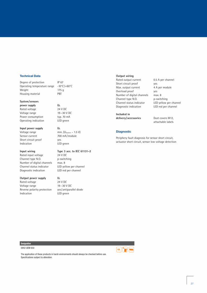
0942 UEM 650
LioN-Link I/O Module with 8 Digital Inputs and Outputs
8 IN/8 OUT universalLioN-Link I/O modulewith 8 digital I/O channels, channels can be used universally as inputs or outputs, M8 sockets (8x), 3 poles, M12 actuator supply
Bit Assignment
Bit 7 6 5 4 3 2 1 0
M8 Input
Byte 0 8 7 6 5 4 3 2 1
M8 Output
Byte 0 8 7 6 5 4 3 2 1
Diagnostic Indication
LED Indication Condition
1...8 yellow channel status
1...8 red periphery faults (actuator short circuit/overload)
I/O red wrong configuration/module exchangedred flashing not recognized by the BusHeadgreen online, communication with BusHead
US green sensor /system power supply
UL green actuator power supply
DIA red common indication for periphery faults
Pin Assignment
LioN-Link connection M12 Actuator/sensor connection M8 Actuator supply M12
1 = Drain2 = 24 V Sensor/System3 = 0 V Sensor/System4 = Data + 5 = Data -
1 = +24 V3 = 0 V4 = In /Out
1 = +24 V2 = n.c.3 = GND (0 V)4 = n.c.5 = Earth
RZ_LioN-Link_Brochure_GB:LioN-Link 12.04.2010 12:56 Uhr Seite 26
27
Technical Data
Degree of protection IP 67Operating temperature range -10°C/+60°CWeight 175 gHousing material PBT
System/sensors power supply US
Rated voltage 24 V DCVoltage range 19–30 V DCPower consumption typ. 70 mA Operating indication LED green
Input power supply US
Voltage range min. (USystem – 1.5 V)Sensor current 700 mA/moduleShort circuit proof yesIndication LED green
Input wiring Type 3 acc. to IEC 61131-2Rated input voltage 24 V DCChannel type N.O. p-switchingNumber of digital channels max. 8Channel status indicator LED yellow per channelDiagnostic indication LED red per channel
Output power supply UL
Rated voltage 24 V DCVoltage range 19–30 V DCReverse polarity protection yes/antiparallel diodeIndication LED green
Designation
0942 UEM 650
The application of these products in harsh environments should always be checked before use.Specifications subject to alteration.
Output wiring Rated output current 0.5 A per channelShort circuit proof yesMax. output current 4 A per moduleOverload proof yesNumber of digital channels max. 8Channel type N.O. p-switchingChannel status indicator LED yellow per channelDiagnostic indication LED red per channel
Included in delivery/accessories Dust covers M12,
attachable labels
Diagnostic
Periphery fault diagnosis for sensor short circuit, actuator short circuit, sensor low voltage detection
��
RZ_LioN-Link_Brochure_GB:LioN-Link 12.04.2010 12:56 Uhr Seite 27
28
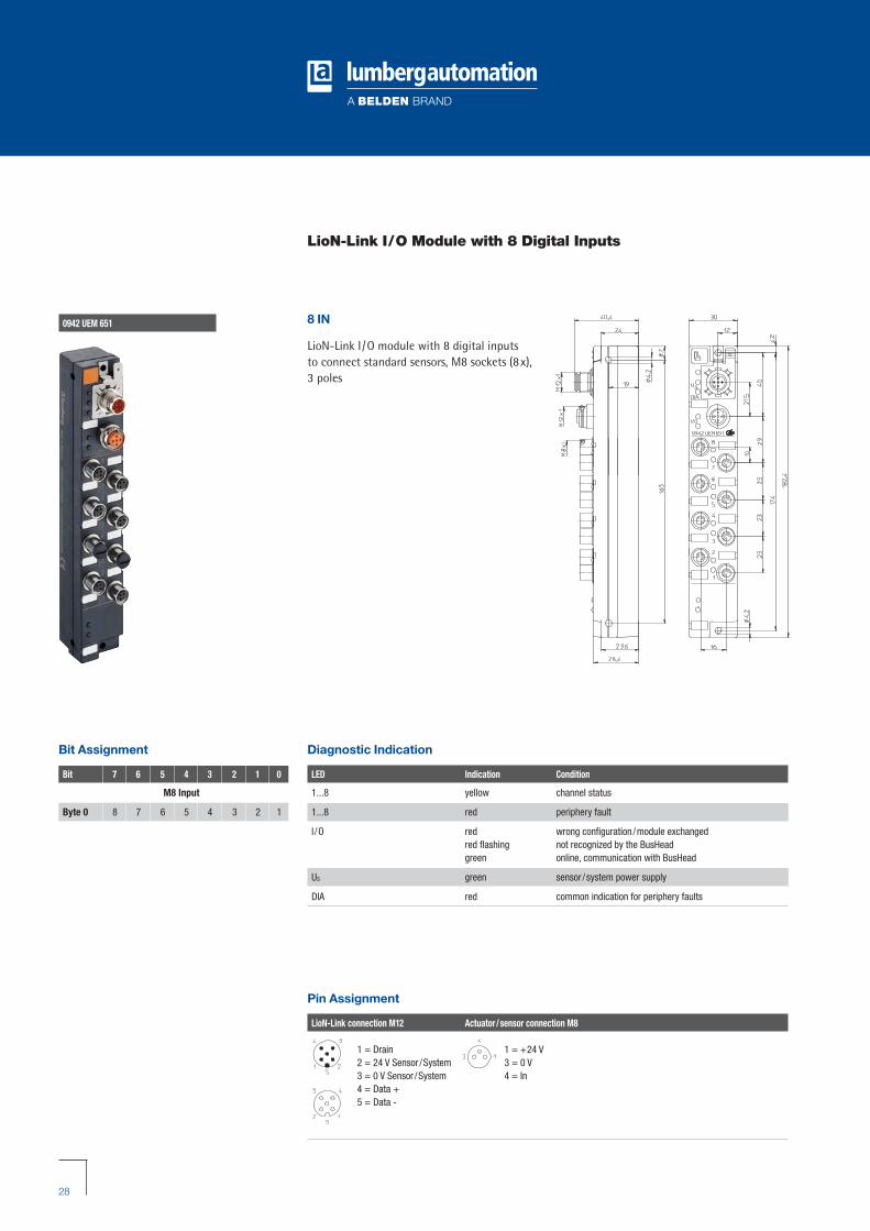
0942 UEM 651
LioN-Link I/O Module with 8 Digital Inputs
8 IN
LioN-Link I/O module with 8 digital inputs to connect standard sensors, M8 sockets (8x),3 poles
Pin Assignment
LioN-Link connection M12 Actuator/sensor connection M8
1 = Drain2 = 24 V Sensor /System3 = 0 V Sensor /System4 = Data + 5 = Data -
1 = +24 V3 = 0 V4 = In
Diagnostic Indication
LED Indication Condition
1...8 yellow channel status
1...8 red periphery fault
I/O red wrong configuration/module exchangedred flashing not recognized by the BusHeadgreen online, communication with BusHead
US green sensor /system power supply
DIA red common indication for periphery faults
Bit Assignment
Bit 7 6 5 4 3 2 1 0
M8 Input
Byte 0 8 7 6 5 4 3 2 1
RZ_LioN-Link_Brochure_GB:LioN-Link 12.04.2010 12:56 Uhr Seite 28

29
Technical Data
Degree of protection IP 67Operating temperature range -10°C/+60°CWeight 175 gHousing material PBT
System/sensors power supply US
Rated voltage 24 V DCVoltage range 19–30 V DCPower consumption typ. 70 mA Operating indication LED green
Input power supply US
Voltage range min. (USystem – 1.5 V)Sensor current 700 mA/module Short circuit proof yesIndication LED green
Input wiring Type 3 acc. to IEC 61131-2Rated input voltage 24 V DCChannel type N.O. p-switchingNumber of digital channels max. 8Channel status indicator LED yellow per channelDiagnostic indication LED red per channel
Included in delivery/accessories Dust covers M12, attachable labels
Diagnostic
Periphery fault diagnosis for sensor short circuit, sensor low voltage detection
Designation
0942 UEM 651
The application of these products in harsh environments should always be checked before use.Specifications subject to alteration.
��
RZ_LioN-Link_Brochure_GB:LioN-Link 12.04.2010 12:56 Uhr Seite 29

30
0942 UEM 600
LioN-Link I/O Module with 8 Digital Inputs and Outputs
8 IN/8 OUT
universal LioN-Link I/O module with 8 digitalI/O channels, channels can be used universallyas inputs or outputs, M12 sockets (4x), 5 poles,M12 actuator supply
Pin Assignment
LioN-Link connection M12 Actuator/sensor connection M12 Actuator supply M12
1 = Drain2 = 24 V Sensor /System3 = 0 V Sensor /System4 = Data + 5 = Data -
1 = +24 V2 = In /Out B3 = 0 V4 = In /Out A5 = Earth
1 = +24 V2 = n.c.3 = GND (0 V)4 = n.c.5 = Earth
Bit Assignment
Bit 7 6 5 4 3 2 1 0
M12 Input
Byte 0 4B 4A 3B 3A 2B 2A 1B 1A
M12 Output
Byte 0 4B 4A 3B 3A 2B 2A 1B 1A
Diagnostic Indication
LED Indication Condition
1...4 A/B yellow channel status
1...4 A/B red periphery fault
I/O red wrong configuration/module exchangedred flashing not recognized by the BusHeadgreen online, communication with BusHead
US green sensor /system power supply
UL green actuator power supply
DIA red common indication for periphery faults
RZ_LioN-Link_Brochure_GB:LioN-Link 12.04.2010 12:56 Uhr Seite 30

31
Technical Data
Degree of protection IP 67Operating temperature range -10°C/+60°CWeight 200 gHousing material PBT
System/sensors power supply US
Rated voltage 24 V DCVoltage range 19–30 V DCPower consumption typ. 70 mA Operating indication LED green
Input power supply US
Voltage range min. (USystem – 1.5 V)Sensor current 700 mA/module Short circuit proof yesIndication LED green
Input wiring Type 3 acc. to IEC 61131-2Rated input voltage 24 V DCChannel type N.O. p-switchingNumber of digital channels max. 8Channel status indicator LED yellow per channelDiagnostic indication LED red per channel
Output power supply UL
Rated voltage 24 V DCVoltage range 19–30 V DCReverse polarity protection yes/antiparallel diodeIndication LED green
Output wiring Rated output current 1.6 A per channelShort circuit proof yesMax. output current 4 A per moduleOverload proof yesNumber of digital channels max. 8Channel type N.O. p-switchingChannel status indicator LED yellow per channelDiagnostic indication LED red per channel
Designation
0942 UEM 600
The application of these products in harsh environments should always be checked before use.Specifications subject to alteration.
��
Included in delivery/accessoriesDust covers M12, attachable labels
Diagnostic
Periphery fault diagnosis for sensor short circuit, actuator short circuit /channel, sensor low voltage detection
RZ_LioN-Link_Brochure_GB:LioN-Link 12.04.2010 12:56 Uhr Seite 31

32
0942 UEM 601
LioN-Link I/O Module with 8 Digital Inputs
8 IN
LioN-Link I/O module with 8 digital inputs to connect standard sensors, M12 sockets (4x),5 poles
Diagnostic Indication
LED Indication Condition
1...4 A/B yellow channel status
1...4 A red periphery fault
I/O red wrong configuration/module exchangedred flashing not recognized by the BusHeadgreen online, communication with BusHead
US green sensor /system power supply
DIA red common indication for periphery faults
Pin Assignment
LioN-Link connection M12 Actuator/sensor connection M12
1 = Drain2 = 24 V Sensor /System3 = 0 V Sensor /System4 = Data + 5 = Data -
1 = +24 V2 = In B3 = GND (0 V)4 = In A5 = Earth
Bit Assignment
Bit 7 6 5 4 3 2 1 0
M12 Input
Byte 0 4B 4A 3B 3A 2B 2A 1B 1A
RZ_LioN-Link_Brochure_GB:LioN-Link 12.04.2010 12:56 Uhr Seite 32

33
Technical Data
Degree of protection IP 67Operating temperature range -10°C/+60°CWeight 175 gHousing material PBT
System/sensors power supply US
Rated voltage 24 V DCVoltage range 19–30 V DCPower consumption typ. 70 mA Operating indication LED green
Input power supply US
Voltage range min. (USystem – 1.5 V)Sensor current 700 mA/module Short circuit proof yesIndication LED green
Input wiring Type 3 acc. to IEC 61131-2Rated input voltage 24 V DCChannel type N.O. p-switchingNumber of digital channels max. 8Channel status indicator LED yellow per channelDiagnostic indication LED red per channel
Included in delivery/accessories Dust covers M12, attachable labels
Diagnostic
Periphery fault diagnosis for sensor short circuit, sensor low voltage detection
Designation
0942 UEM 601
The application of these products in harsh environments should always be checked before use.Specifications subject to alteration.
��
RZ_LioN-Link_Brochure_GB:LioN-Link 12.04.2010 12:56 Uhr Seite 33

34
0942 UEM 630
LioN-Link I/O Module with 4 Analog Inputs
4 IN
LioN-Link I/O module with 4 analog inputs0(4)–20 mA to connect standard sensors, M12 sockets (4x), 5 poles
Diagnostic Indication
LED Indication Condition
1...4 yellow channel status
1...4 DIA red periphery fault
I/O red wrong configuration/module exchangedred flashing not recognized by the BusHeadgreen online, communication with BusHead
US green sensor /system power supply
DIA red common indication for periphery faults
Pin Assignment
LioN-Link connection M12 Sensor connection M12
1 = Drain2 = +24 V 3 = GND (0 V) 4 = Data + 5 = Data -
1 = +24 V2 = Signal +3 = GND (0 V)4 = GND (0 V)5 = Earth
Bit Assignment
Bit 7 6 5 4 3 2 1 0
M12 Input
Byte 0Byte 1Byte 2Byte 3Byte 4Byte 5Byte 6Byte 7
Channel 1
Channel 2
Channel 3
Channel 4
RZ_LioN-Link_Brochure_GB:LioN-Link 12.04.2010 12:57 Uhr Seite 34

35
Technical Data
Degree of protection IP 67Operating temperature range -10°C/+60°CWeight 175 gHousing material PBT
Input power supply US
Voltage range 24 V DCSensor current 700 mA/moduleShort circuit proof yesPower consumption system: typ. 50 mA
Input wiring Current inputsMeasurement signal (0)4–20 mAResolution 12 bit + signMeasuring fault (full measuring range) ±1.2%Temperature fault (full measuring range) ±0.01%/KOutput formats Siemens S7Input impedance ≤400 ΩConversion time typ. 25 ms per channelPotential separation channel /channel noPotential separation power/channel noNumber of analog channels max. 4Channel status indicator LED yellow: channel active
Module diagnostic Module status Sensor short circuitIndication LED red/green (I/O)
Channel diagnostic0–20 mA Overload at current measurement4–20 mA Overload at current measurement/Underflow/Broken wire Indication LED red (DIA)
GSD configurationModule way Resolution 12 bit, 10 bit (Conversion time ≤3 ms/module)Channel way Measuring range 0–20 mA or 4–20 mA
Broken wire (only 4–20 mA), Channel on/off, Diagnostic on/off
Included in delivery/accessories Dust covers M12, attachable labels
Designation
0942 UEM 630
The application of these products in harsh environments should always be checked before use.Specifications subject to alteration.
��
RZ_LioN-Link_Brochure_GB:LioN-Link 12.04.2010 12:57 Uhr Seite 35

36
0942 UEM 631
LioN-Link I/O Module with 4 Analog Inputs
4 IN
LioN-Link I/O module with 4 analog inputs 0–10 V to connect standard sensors,M12 sockets (4x), 5 poles
Diagnostic Indication
LED Indication Condition
1...4 yellow channel status
1...4 DIA red periphery fault
I/O red wrong configuration/module exchangedred flashing not recognized by the BusHeadgreen online, communication with BusHead
US green sensor /system power supply
DIA red common indication for periphery faults
Pin Assignment
LioN-Link connection M12 Sensor connection M12
1 = Drain2 = +24 V 3 = GND (0 V) 4 = Data + 5 = Data -
1 = +24 V2 = Signal +3 = GND (0 V)4 = GND (0 V)5 = Earth
Bit Assignment
Bit 7 6 5 4 3 2 1 0
M12 Input
Byte 0Byte 1Byte 2Byte 3Byte 4Byte 5Byte 6Byte 7
Channel 1
Channel 2
Channel 3
Channel 4
RZ_LioN-Link_Brochure_GB:LioN-Link 12.04.2010 12:57 Uhr Seite 36
37
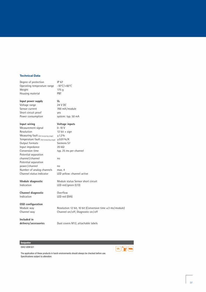
Technical Data
Degree of protection IP 67Operating temperature range -10°C/+60°CWeight 175 gHousing material PBT
Input power supply US
Voltage range 24 V DCSensor current 700 mA/moduleShort circuit proof yesPower consumption system: typ. 50 mA
Input wiring Voltage inputsMeasurement signal 0-10 VResolution 12 bit + signMeasuring fault (full measuring range) ±1.2%Temperature fault (full measuring range) ±0.01%/KOutput formats Siemens S7Input impedance 20 kΩConversion time typ. 25 ms per channelPotential separation channel /channel noPotential separation power/channel noNumber of analog channels max. 4Channel status indicator LED yellow: channel active
Module diagnostic Module status Sensor short circuitIndication LED red/green (I/O)
Channel diagnostic OverflowIndication LED red (DIA)
GSD configurationModule way Resolution 12 bit, 10 bit (Conversion time ≤3 ms/module)Channel way Channel on/off, Diagnostic on/off
Included in delivery/accessories Dust covers M12, attachable labels
Designation
0942 UEM 631
The application of these products in harsh environments should always be checked before use.Specifications subject to alteration.
��
RZ_LioN-Link_Brochure_GB:LioN-Link 12.04.2010 12:57 Uhr Seite 37

38
0942 UEM 783
LioN-Link I/O Module with 8 Digital Inputs and 4 Digital or Analog Outputs (Motion Drive Control)
8 IN/4 OUT (digital or analog)
LioN-Link Motion module with 8 digital inputs and 4 universal outputs that can be configured for the connection of brushless motors, DC motors or for valves. System specific specifications such as speed and acceleration/deceleration can be transmittedvia the DP-V1* protocol. Power supply is via a connecting cable with 7/8" connector.
* = Only with 0940 PSL 602
Diagnostic Indication
LED Indication Condition
1...4 A/B yellow channel status
1...4 A/B red periphery faults (actuator short circuit/overload)
I/O red wrong configuration/module exchangedred flashing not recognized by the BusHeadgreen online, communication with BusHead
US green sensor /system power supply
UL green actuator power supply
DIA red common indication for periphery faults
Pin Assignment
LioN-Link connection M12 Actuator/sensor connection M12 Power supply for motors
1 = Drain2 = 24 V Sensor /System3 = 0 V Sensor /System4 = Data +5 = Data -
In Out1 = +24 V DC 1 = +24 V DC2 = In B 2 = Dir3 = 0 V 3 = 0 V4 = In A 4 = Dia5 = Earth 5 = Speed ( 0-10 V)
Function Wire color1 = Diag. Out Black2 = +24 V Brown3 = 0 V Blue
Socket 8 Socket 7 Socket 6 Socket 5
Bit Assignment
Bit 7 6 5 4 3 2 1 0
M12 Input
Byte 0 4B 4A 3B 3A 2B 2A 1B 1A
M12 Output
Byte 0 Dir Start Dir Start Dir Start Dir Start
RZ_LioN-Link_Brochure_GB:LioN-Link 12.04.2010 12:57 Uhr Seite 38

39
Technical Data
Degree of protection IP 67Operating temperature range -10°C/+60°CWeight 175 gHousing material PBT
System/sensors power supply US
Rated voltage 24 V DCVoltage range 19–30 V DCPower consumption typ. 100 mA Reverse polarity protection noOperating indication LED green
Input power supply US
Voltage range 24 V DCSensor current 700 mA/module Short circuit proof yesIndication LED greenConnection M12 connector (5 poles),
see pin assignment
Input wiring Type 3 acc. to IEC 61131-2Rated input voltage 24 V DCInput current at 24 V DC typ. 5 mA Short circuit proof sensor supply yesChannel type N.O. p-switchingNumber of digital channels max. 8Channel status indicator LED yellow per channelDiagnostic indication LED red per channelConnection M12 coupling (5 poles),
see pin assignment
Output power supply UL
Rated voltage 24 V DCVoltage range 19–27 V DCReverse polarity protection yes/antiparallel diodeIndication LED greenConnection 7/8" connector (3 poles), see pin
assignment
Designation
0942 UEM 783
The application of these products in harsh environments should always be checked before use.Specifications subject to alteration.
��
Output wiring I Type 3 acc. to IEC 61131-2Output module Pin 2
Rated output current 1.5 A per channelSignal status “1” max. 4 A (max. 50 ms)Signal status “0” max. 1 mA (standard specification)Short circuit proof yesMax. output current 7.2 A per moduleOverload proof yesNumber of digital channels max. 4Channel type N.O. p-switchingChannel status indicator LED yellow per channelDiagnostic indication LED red per channelConnection M12 coupling (5 poles),
see pin assignment
Output wiring II Output module Pin 5Voltage range 0–10 V DC (motor dependent)Number of channels max. 4 analogChannel type PWM outputConnection M12 coupling (5 poles),
see pin assignment
Included in delivery/accessories Dust covers M12,
attachable labels
Diagnostic
Periphery fault diagnosis for sensor short circuit, actuator short circuit /channel, sensor low voltage detection
Note
Only to be used in combination with BusHead 0940 PSL 602. Module used to control brushless (EC) motors as well as brush loaded (DC) motors and all types of digital actuators (e.g. valves or direct current motors)
RZ_LioN-Link_Brochure_GB:LioN-Link 12.04.2010 12:57 Uhr Seite 39

40
0942 UEM 670
LioN-Link I/O Module with 8 Digital Inputs and Outputs(Shadow Mode)
8 IN/8 OUT universal
LioN-Link I/O module with 8 digital I/O channels, channels can be used universally as inputs or outputs, M8 sockets, 3 poles
Input or output functionality can be switched off while retaining the respective addressrange*.
* = Only with 0940 PSL 603
Pin Assignment
LioN-Link connection M12 Actuator/sensor connection M8 Actuator supply M12
1 = Drain2 = 24 V Sensor /System3 = 0 V Sensor /System4 = Data + 5 = Data -
1 = +24 V3 = 0 V4 = In /Out
1 = +24 V2 = n.c.3 = GND (0 V)4 = n.c.5 = Earth
Bit Assignment
Bit 7 6 5 4 3 2 1 0
M8 Input
Byte 0 8 7 6 5 4 3 2 1
M8 Output
Byte 0 8 7 6 5 4 3 2 1
Diagnostic Indication
LED Indication Condition
1...8 yellow channel status
1...8 red periphery faults (actuator short circuit/overload)
I/O red wrong configuration/module exchangedred flashing not recognized by the BusHeadgreen online, communication with BusHead
US green sensor /system power supply
UL green actuator power supply
DIA red common indication for periphery faults
0942 UEM 670
RZ_LioN-Link_Brochure_GB:LioN-Link 12.04.2010 12:57 Uhr Seite 40

41
Technical Data
Degree of protection IP 67Operating temperature range -10°C/+60°CWeight 175 gHousing material PBT
System/sensors power supply US
Rated voltage 24 V DCVoltage range 19–30 V DCPower consumption typ. 70 mA Operating indication LED green
Input power supply US
Voltage range 24 V DC Sensor current 700 mA/moduleShort circuit proof yesIndication LED green
Input wiring Type 3 acc. to IEC 61131-2Rated input voltage 24 V DCChannel type N.O. p-switchingNumber of digital channels max. 8Channel status indicator LED yellow per channelDiagnostic indication LED red per channel
Output power supply UL
Rated voltage 24 V DCVoltage range 19–30 V DCReverse polarity protection yes/antiparallel diodeIndication LED green
Output wiring Rated output current 0.5 A per channelShort circuit proof yesMax. output current 4 A per moduleOverload proof yesNumber of digital channels max. 8Channel type N.O. p-switchingChannel status indicator LED yellow per channelDiagnostic indication LED red per channel
Designation
0942 UEM 670
The application of these products in harsh environments should always be checked before use.Specifications subject to alteration.
��
Included in delivery/accessories Dust covers M12,
attachable labels
Diagnostic
Periphery fault diagnosis for sensor short circuit, actuator short circuit, sensor low voltage detection
Note
This I/O module can only be used with the BusHead 0940 PSL 603.
In addition to being used as a dedicated input or output module, this module can also be operated in Shadow Input and Shadow Output mode.The process data in both modes is 1 input and 1 output byte. In Shadow Input mode the input byte is set to 0. The outputs can be activated via the output byte. In Shadow Output mode,however, the outputs cannot be activated and the inputs can be used normally.
RZ_LioN-Link_Brochure_GB:LioN-Link 12.04.2010 12:57 Uhr Seite 41
42
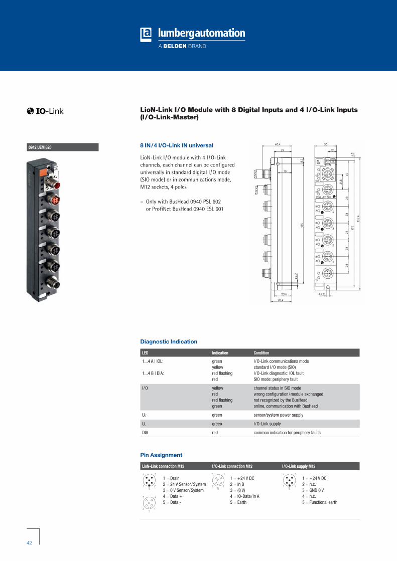
0942 UEM 620
LioN-Link I/O Module with 8 Digital Inputs and 4 I/O-Link Inputs(I/O-Link-Master)
8 IN/4 I/O-Link IN universal
LioN-Link I/O module with 4 I/O-Link channels, each channel can be configured universally in standard digital I/O mode (SIO mode) or in communications mode, M12 sockets, 4 poles
– Only with BusHead 0940 PSL 602or ProfiNet BusHead 0940 ESL 601
Diagnostic Indication
LED Indication Condition
1...4 A | IOL: green I/O-Link communications modeyellow standard I/O mode (SIO)
1...4 B | DIA: red flashing I/O-Link diagnostic: IOL faultred SIO mode: periphery fault
I/O yellow channel status in SIO modered wrong configuration/module exchangedred flashing not recognized by the BusHeadgreen online, communication with BusHead
US green sensor/system power supply
UL green I/O-Link supply
DIA red common indication for periphery faults
Pin Assignment
LioN-Link connection M12 I/O-Link connection M12 I/O-Link supply M12
1 = Drain2 = 24 V Sensor /System3 = 0 V Sensor /System4 = Data + 5 = Data -
1 = +24 V DC2 = In B3 = (0 V)4 = IO-Data/ In A5 = Earth
1 = +24 V DC2 = n.c.3 = GND 0 V4 = n.c.5 = Functional earth
RZ_LioN-Link_Brochure_GB:LioN-Link 12.04.2010 12:57 Uhr Seite 42

43
Technical Data
Degree of protection IP 67Operating temperature range -10°C/+60°CWeight 175 gHousing material PBT
System/sensors power supply US
Rated voltage 24 V DCVoltage range 19–30 V DCPower consumption typ. 70 mA Operating indication LED green
Input power supply US
Voltage range 24 V DC Sensor current 700 mA/moduleShort circuit proof yesIndication LED green
Designation
0942 UEM 620
The application of these products in harsh environments should always be checked before use.Specifications subject to alteration.
��
Input wiring Type 3 acc. to IEC 61131-2Rated input voltage 24 V DCChannel type N.O. p-switchingNumber of digital channels max. 8Channel status indicator LED A green/yellowDiagnostic indication LED red
I/O-Link power supply UL
Rated voltage 24 V DCVoltage range 19–30 V DCReverse polarity protection yes/antiparallel diodeIndication LED green
I/O-Link Specification 1.0
Included in delivery/accessories Dust covers M12, attachable labels
Note
The information in the operating instructions must be observed
Bit Assignment
Channel 1: 1 byte, 1 word or not configuredByte Byte 0 Byte 1Bit 15 14 13 12 11 10 9 8 7 6 5 4 3 2 1 0Port 1 1
Channel 2: 1 byte, 1 word or not configuredByte Byte 2 Byte 3Bit 15 14 13 12 11 10 9 8 7 6 5 4 3 2 1 0Port 2 2Assignment I/O-Link-Device process data/High Byte I/O-Link-Device process data/Low Byte
Channel 3: 1 byte, 1 word or not configuredByte Byte 4 Byte 5Bit 15 14 13 12 11 10 9 8 7 6 5 4 3 2 1 0Port 3 3Assignment I/O-Link-Device process data/High Byte I/O-Link-Device process data/Low Byte
Channel 4: 1 byte, 1 word or not configuredByte Byte 6 Byte 7Bit 15 14 13 12 11 10 9 8 7 6 5 4 3 2 1 0Port 4 4Assignment I/O-Link-Device process data/High Byte I/O-Link-Device process data/Low Byte
2 Bytes (module status)Byte Byte 8 Byte 9Bit 15 14 13 12 11 10 9 8 7 6 5 4 3 2 1 0Port 4 3 2 1 4 3 2 1 4 3 2 1Assignment 1=IO-Link 1=IO-Link 1=IO-Link 1=IO-Link
Pin 4 = DI Pin 4 = DI Pin 4 = DI Pin 4 = DI 0=SIO 0=SIO 0=SIO 0=SIO Pin 2 = DI Pin 2 = DI Pin 2 = DI Pin 2 = DI
RZ_LioN-Link_Brochure_GB:LioN-Link 12.04.2010 12:57 Uhr Seite 43

44
0942 UEM 700
LioN-Link I/O Module with 16 Digital Inputs and Outputs
16 IN/16 OUT universal
LioN-Link I/O module with 16 digital I/Ochannels, channels can be used universally as inputs or outputs, M12 sockets (8x), 5 poles, 7/8" actuator supply
Pin Assignment
LioN-Link connection M12 Actuator/sensor connection M12 Actuator supply 7/8"
1 = Drain2 = 24 V Sensor /System3 = 0 V Sensor /System4 = Data + 5 = Data -
1 = +24 V2 = In /Out B3 = 0 V4 = In /Out A5 = Earth
1 = GND (0 V)2 = GND (0 V)3 = Earth 4 = 24 V (UL 1–4)5 = 24 V (UL 5-8)
Diagnostic Indication
LED Indication Condition
1...8 A/B yellow channel status
1...8 red periphery faults (actuator short circuit/overload)
I/O red wrong configuration/module exchangedred flashing not recognized by the BusHeadgreen online, communication with BusHead
US green sensor /system power supply
UL green actuator power supply
DIA red common indication for periphery faults
Bit Assignment
Bit 7 6 5 4 3 2 1 0
M12 Input
Byte 0 4B 4A 3B 3A 2B 2A 1B 1AByte 1 8B 8A 7B 7A 6B 6A 5B 5A
M12 Output
Byte 0 4B 4A 3B 3A 2B 2A 1B 1AByte 1 8B 8A 7B 7A 6B 6A 5B 5A
RZ_LioN-Link_Brochure_GB:LioN-Link 12.04.2010 12:57 Uhr Seite 44

45
Technical Data
Degree of protection IP 67Operating temperature range -10°C/+60°CWeight 375 gHousing material PBT
System/sensors power supply US
Rated voltage 24 V DCVoltage range 19–30 V DCPower consumption typ. 100 mA
Input power supply US
Voltage range min. (USystem – 1.5 V)Sensor current 700 mA Short circuit proof yesIndication LED green
Input wiring Type 3 acc. to IEC 61131-2Rated input voltage 24 V DCChannel type N.O. p-switchingNumber of digital channels max. 16Channel status indicator LED yellow per channel
Output power supply UL
Rated voltage 24 V DCVoltage range 19–30 V DCReverse polarity protection yes/antiparallel diodeIndication LED green
Output wiringRated output current 1.6 A per channelShort circuit proof yesMax. output current 9 A (12 A*) per module* Test proven and approved under the following conditions:· Looped through sensor / system power supply max. 2.5 A· Power supply cable STL 204 (5 x1.00 mm2)
· Operating temperature range max. 40°C
Overload proof yesNumber of digital channels max. 16Channel type N.O. p-switchingChannel status indicator LED yellow per channelDiagnostic indication LED red per channel
Designation
0942 UEM 700
The application of these products in harsh environments should always be checked before use.Specifications subject to alteration.
��
Diagnostic
Periphery fault diagnosis for sensor short circuit, actuator short circuit, sensor low voltage detection
RZ_LioN-Link_Brochure_GB:LioN-Link 12.04.2010 12:57 Uhr Seite 45

46
0942 UEM 701
LioN-Link I/O Module with 16 Digital Inputs
16 IN
LioN-Link I/O module with 16 digital inputs to connect standard sensors, M12 sockets (8x), 5 poles
Pin Assignment
LioN-Link connection M12 Actuator/sensor connection M12
1 = Drain2 = 24 V Sensor /System3 = 0 V Sensor /System4 = Data + 5 = Data -
1 = +24 V2 = In /Out B3 = 0 V4 = In /Out A5 = Earth
Diagnostic Indication
LED Indication Condition
1...8 A/B yellow channel status
1...8 A red periphery faults (actuator short circuit/overload)
I/O red wrong configuration/module exchangedred flashing not recognized by the BusHeadgreen online, communication with BusHead
US green sensor /system power supply
DIA red common indication for periphery faults
Bit Assignment
Bit 7 6 5 4 3 2 1 0
M12 Input
Byte 0 4B 4A 3B 3A 2B 2A 1B 1AByte 1 8B 8A 7B 7A 6B 6A 5B 5A
RZ_LioN-Link_Brochure_GB:LioN-Link 12.04.2010 12:57 Uhr Seite 46

47
Technical Data
Degree of protection IP 67Operating temperature range -10°C/+60°CWeight 275 gHousing material PBT
System/sensors power supply US
Rated voltage 24 V DCVoltage range 19–30 V DCPower consumption typ. 100 mA
Input power supply US
Voltage range min. (USystem – 1.5 V)Sensor current 700 mA Short circuit proof yesIndication LED green
Input wiring Type 3 acc. to IEC 61131-2Rated input voltage 24 V DCChannel type N.O. p-switchingNumber of digital channels max. 16Channel status indicator LED yellow per channel
Diagnostic
Periphery fault diagnosis for sensor short circuit, sensor low voltage detection
Designation
0942 UEM 701
The application of these products in harsh environments should always be checked before use.Specifications subject to alteration.
��
RZ_LioN-Link_Brochure_GB:LioN-Link 12.04.2010 12:57 Uhr Seite 47

Pin Assignment
LioN-Link connection M12 Actuator connection M12 Actuator supply M12
1 = +24 V DC2 = +24 V DC3 = GND 0 V4 = GND 0 V5 = Functional earth
48
0942 UEM 602
LioN-Link I/O Module with 4 Digital Outputs
4 OUT
LioN-Link I/O module with 4 digital outputs,M12 sockets (4x), 5 poles, 2 A per channel, one channel per socket
1 = Drain2 = 24 V Sensor /System3 = 0 V Sensor /System4 = Data + 5 = Data -
1 = n.c.2 = n.c.3 = 0 V4 = Out A5 = Earth
Bit Assignment
Bit 7 6 5 4 3 2 1 0
M12 Output
Byte 0 - - - - 4A 3A 2A 1A
Diagnostic Indication
LED Indication Condition
1...4 A yellow channel status
1..4 DIA red periphery fault /output active with no actuator supply voltage
I/O red wrong configuration/module exchangedred flashing not recognized by the BusHeadgreen online, communication with BusHead
US green sensor /system power supply
UL green actuator power supply
DIA red common indication for periphery faults
0942 UEM 602
RZ_LioN-Link_Brochure_GB:LioN-Link 12.04.2010 12:57 Uhr Seite 48

49
Technical Data
Degree of protection IP 67Operating temperature range -10°C/+60°CWeight 200 gHousing material PBT
System/sensors power supply US
Rated voltage 24 V DCVoltage range 19–30 V DCPower consumption typ. 70 mA
Output power supply UL
Rated voltage 24 V DCVoltage range 19–30 V DCReverse polarity protection yes/antiparallel diodeIndication LED greenConnection M12 connector (3 or 5 poles)
Output wiringRated output current 2.0 A per channelShort circuit proof yesMax. output current 4 A (3 pole supply line); 6 A (5 pole supply line)Overload proof yesNumber of digital channels max. 4Channel type N.O. p-switchingChannel status indicator LED yellow per channelDiagnostic indication LED red per channel
Included in delivery/accessories Dust covers M12, attachable labels
Diagnostic
Periphery fault diagnosis for actuator short circuit /overload per channel
Note
Particularly suitable for the control of hydraulic valves
Designation
0942 UEM 602
The application of these products in harsh environments should always be checked before use.Specifications subject to alteration.
��
RZ_LioN-Link_Brochure_GB:LioN-Link 12.04.2010 12:57 Uhr Seite 49

50
0942 UEM 612
LioN-Link I/O Module with 4 Digital Outputs
4 OUT
LioN-Link I/O module with 4 digital outputs,M12 sockets (4x), 5 poles, M12 actuator supply, 2 A per channel, one channel persocket
– Suitable for safety critical applicationswithin Performance Levels A through D
Bit Assignment
Bit 7 6 5 4 3 2 1 0
M12 Output
Byte 0 - - - - 4A 3A 2A 1A
Pin Assignment
LioN-Link connection M12 Actuator connection M12 Actuator supply M12
1 = +24 V DC2 = +24 V DC3 = GND 0 V4 = GND 0 V5 = Functional earth
1 = Drain2 = 24 V Sensor /System3 = 0 V Sensor /System4 = Data + 5 = Data -
1 = n.c.2 = n.c.3 = 0 V4 = Out A5 = Earth
Diagnostic Indication
LED Indication Condition
1...4 A yellow channel status
1..4 DIA red periphery fault /output active with no actuator supply voltage
I/O red wrong configuration/module exchangedred flashing not recognized by the BusHeadgreen online, communication with BusHead
US green sensor /system power supply
UL green actuator power supply
DIA red common indication for periphery faults
0942 UEM 612
RZ_LioN-Link_Brochure_GB:LioN-Link 12.04.2010 12:57 Uhr Seite 50

51
Technical Data
Degree of protection IP 67Operating temperature range -10°C/+60°CWeight 200 gHousing material PBT
System/sensors power supply US
Rated voltage 24 V DCVoltage range 19–30 V DCPower consumption typ. 70 mAOperating indication LED green
Output power supply UL
Rated voltage 24 V DCVoltage range 19–28.8 V DC (SELV/PELV acc. to EN60950-1)Reverse polarity protection yes/antiparallel diode, external fuse with
4/6 A medium time lag mandatoryIndication LED greenConnection M12 connector (3 or 5 poles)
Output wiringRated output current 2.0 A per channelShort circuit proof yesMax. output current 4 A (3 pole supply line); 6 A (5 pole supply line)Overload proof yesNumber of digital channels max. 4Channel type N.O. p-switchingChannel status indicator LED yellow per channelDiagnostic indication LED red per channel
Included in delivery/accessories Dust covers M12, attachable labels
Diagnostic
Periphery fault diagnosis for actuator short circuit/overload per channel
Designation
0942 UEM 612
The application of these products in harsh environments should always be checked before use.Specifications subject to alteration.
��
Note
Due to the need to guarantee reliable, all pole disconnection of the output voltage supply on the customer side, utilization in emergencypower off circuits is possible for applicationsup to Performance Level D. The absence of reaction between the logic and output supplycircuits in the event of a hardware fault in themodule is guaranteed.
The instructions in the LioN-Link manual mustbe observed in this case.
RZ_LioN-Link_Brochure_GB:LioN-Link 12.04.2010 12:57 Uhr Seite 51
52
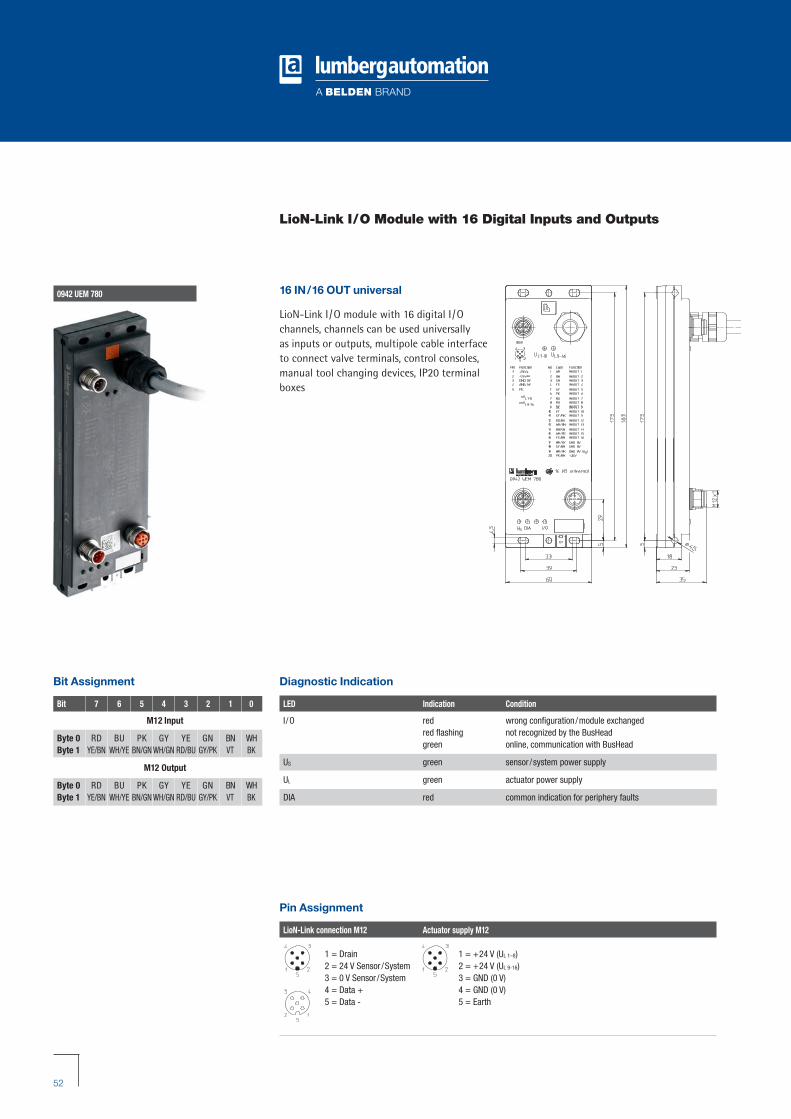
0942 UEM 780
LioN-Link I/O Module with 16 Digital Inputs and Outputs
Pin Assignment
LioN-Link connection M12 Actuator supply M12
1 = Drain2 = 24 V Sensor /System3 = 0 V Sensor /System4 = Data + 5 = Data -
1 = +24 V (UL 1–8)2 = +24 V (UL 9-16)3 = GND (0 V)4 = GND (0 V)5 = Earth
Diagnostic Indication
LED Indication Condition
I /O red wrong configuration/module exchangedred flashing not recognized by the BusHeadgreen online, communication with BusHead
US green sensor /system power supply
UL green actuator power supply
DIA red common indication for periphery faults
Bit Assignment
Bit 7 6 5 4 3 2 1 0
M12 Input
Byte 0 RD BU PK GY YE GN BN WHByte 1 YE/BN WH/YE BN/GN WH/GN RD/BU GY/PK VT BK
M12 Output
Byte 0 RD BU PK GY YE GN BN WHByte 1 YE/BN WH/YE BN/GN WH/GN RD/BU GY/PK VT BK
16 IN/16 OUT universal
LioN-Link I/O module with 16 digital I/Ochannels, channels can be used universally as inputs or outputs, multipole cable interfaceto connect valve terminals, control consoles,manual tool changing devices, IP20 terminalboxes
RZ_LioN-Link_Brochure_GB:LioN-Link 12.04.2010 12:57 Uhr Seite 52

53
Technical Data
Degree of protection IP 67Operating temperature range -10°C/+60°CWeight 800 g (with 5 m cable)Housing material PBT
System/sensors power supply US
Rated voltage 24 V DCVoltage range 19–30 V DCPower consumption 140 mA
Input power supply US
Voltage range min. (USystem – 1.5 V)Sensor current 700 mA Short circuit proof yesIndication LED green
Input wiring Type 3 acc. to IEC 61131-2Rated input voltage 24 V DCChannel type N.O. p-switchingNumber of digital channels max. 16
Output power supply UL
Rated voltage 24 V DCVoltage range 19–30 V DCReverse polarity protection yes/antiparallel diodeIndication LED green
Output wiringRated output current 0.5 A per channelShort circuit proof yesMax. output current 6 A (3 A per group)Group 1 Channel 1–8Group 2 Channel 9–16Overload proof yesNumber of digital channels max. 16Channel type N.O. p-switching
Designation
0942 UEM 780/... M
The application of these products in harsh environments should always be checked before use.Specifications subject to alteration.
��
Diagnostic
Periphery fault diagnosis for sensor short circuit, actuator short circuit, sensor low voltage detection
RZ_LioN-Link_Brochure_GB:LioN-Link 12.04.2010 12:57 Uhr Seite 53
54
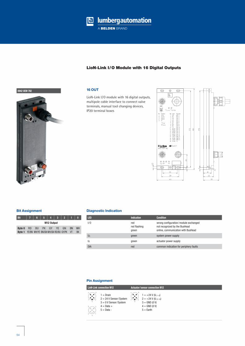
0942 UEM 782
LioN-Link I/O Module with 16 Digital Outputs
Pin Assignment
LioN-Link connection M12 Actuator/sensor connection M12
1 = Drain2 = 24 V Sensor /System3 = 0 V Sensor /System4 = Data + 5 = Data -
1 = +24 V (UL 1–8)2 = +24 V (UL 9–16)3 = GND (0 V)4 = GND (0 V)5 = Earth
Diagnostic Indication
LED Indication Condition
I /O red wrong configuration/module exchangedred flashing not recognized by the BusHeadgreen online, communication with BusHead
US green system power supply
UL green actuator power supply
DIA red common indication for periphery faults
Bit Assignment
Bit 7 6 5 4 3 2 1 0
M12 Output
Byte 0 RD BU PK GY YE GN BN WHByte 1 YE/BN WH/YE BN/GN WH/GN RD/BU GY/PK VT BK
16 OUT
LioN-Link I/O module with 16 digital outputs,multipole cable interface to connect valve terminals, manual tool changing devices, IP20 terminal boxes
RZ_LioN-Link_Brochure_GB:LioN-Link 12.04.2010 12:57 Uhr Seite 54

55
Technical Data
Degree of protection IP 67Operating temperature range -10°C/+60°CWeight 320 g (with 1 m cable)Housing material PBT
System power supply US
Rated voltage 24 V DCVoltage range 19–30 V DCPower consumption 40 mA
Output power supply UL
Rated voltage 24 V DCVoltage range 19–30 V DCReverse polarity protection yes/antiparallel diodeIndication LED green
Output wiringRated output current 0.5 A per channelShort circuit proof yesMax. output current 6 A (3 A per group)Group 1 Channel 1–8Group 2 Channel 9-16Overload proof yesNumber of digital channels max. 16Channel type N.O. p-switching
Diagnostic
Periphery fault diagnosis for actuator short circuit
Designation
0942 UEM 782/... M
The application of these products in harsh environments should always be checked before use.Specifications subject to alteration.
��
RZ_LioN-Link_Brochure_GB:LioN-Link 12.04.2010 12:57 Uhr Seite 55
56
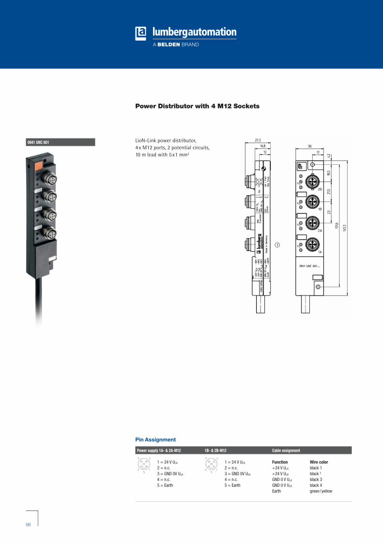
0941 UNC 601
Power Distributor with 4 M12 Sockets
LioN-Link power distributor, 4x M12 ports, 2 potential circuits, 10 m lead with 5x1 mm2
Pin Assignment
Power supply 1A- & 2A-M12 1B- & 2B-M12 Cable assignment
1 = 24 V ULA
2 = n.c.3 = GND 0V ULA
4 = n.c.5 = Earth
1 = 24 V ULB
2 = n.c.3 = GND 0V ULB
4 = n.c.5 = Earth
Function Wire color+24 V ULA black 1+24 V ULB black 2
GND 0 V ULA black 3GND 0 V ULB black 4Earth green/yellow
RZ_LioN-Link_Brochure_GB:LioN-Link 12.04.2010 12:57 Uhr Seite 56
57
Technical Data
MaterialHousing PBTContact holder PAContact M12 CuSn, pre-nickeled and 0.3 µm gold plated threaded bush CuZn, nickel platedO-ring FKM
Operating temperature range -25°C/+70°C
Mechanical dataDegree of protection IP 67
Only in the locked or bolted state with the corresponding counterparts or dust covers
Electrical data Type 3 acc. to IEC 61131-2Rated current at 40°C 4 A/port, 12 A/moduleRated voltage 10–30VOperating indication LED greenInsulation resistance >109 ΩDegree of contamination 3
Included in delivery/accessories Dust covers M12, attachable labels
Designation
0941 UNC 601/10M
The application of these products in harsh environments should always be checked before use.Specifications subject to alteration.
��
RZ_LioN-Link_Brochure_GB:LioN-Link 12.04.2010 12:57 Uhr Seite 57

58
Wiring Accessories BusHead
LioN-Link connection, 5 poles Designation
0935 253 10... CAN/DeviceNet signal cable, Thin Cable, M12
RST 5 ... Actuator /sensor cordset, M12 male connector with molded cable
RK(W)T 5 ... Actuator /sensor cordset, M12 female/ female right angle connector with molded cable
RST 5-RKT 5 ... Actuator /sensor cordset, M12 male and female connector
RSC(W) 5/9 Field attachable connector , M12 male/RSC(W) 5/9 male right angle connector or M12 female/ female right
angle connector, with threaded joint
Power supply connection, 5 poles Designation
RKT 5... Actuator /sensor cordset, RKWT 5... M12 female/ female right angle connector with molded cable
0906 UTP 101 T-connector with M12 male/ female connector, 5 poles
0940 PSL 601 0940 CSL 601 Bus connection, 5 poles Designation
0975 254 10... Profibus signal cable, M12, B coded0935 253 10... CAN/DeviceNet signal cable,
Thin Cable, M12
0979 PTX 101 Profibus terminating resistor, M12, B coded 0939 CTX 101 CAN/DeviceNet terminating resistor, M12
RZ_LioN-Link_Brochure_GB:LioN-Link 12.04.2010 12:57 Uhr Seite 58

59
Wiring Accessories I/O Modules
LioN-Link connection, 5 poles Designation
0935 253 10... CAN/DeviceNet signal cable, Thin Cable, M12
RST 5 ... Actuator /sensor cordset, M12 male connector with molded cable
RK(W)T 5... Actuator /sensor cordset, M12 female/ female right angle connector with molded cable
RST 5-RKT 5 ... Actuator /sensor cordset, M12 male and female connector
RSC(W) 5/9 Field attachable connector , M12 male/RSC(W) 5/9 male right angle connector or M12 female/ female right
angle connector, with threaded joint
0906 UTP 104 T-connector /splitter, 2-way, with mounting hole, M12 female connector with two M12 male connectors, 5-poles
Actuator/sensor connection, 3 and 5 poles Designation
RSMV... Actuator /sensor cordset, M8 male connector with molded cable
RSMC... Field attachable connector, RSMCW... M8 male/ male right angle connector, with threaded joint
RST... Actuator /sensor cordset, M12 male connector with molded cable
RSMV-RKM(WV)... Actuator /sensor cordset, RST-RKM... M8/M12 male connector and M8/M12 female/female right
angle connector
RSC... Field attachable connector, RSCW... M12 male/male right angle connector, with threaded joint
0942 UEM 65... 0942 UEM 60... /63...
Power supply connection, 5 poles Designation
RKT 5... Actuator /sensor cordset, RKWT 5... M12 female/ female right angle connector with molded cableRKT 5-226/... M P89
0906 UTP 101 T-connector with M12 male/ female connector, 5 poles
RZ_LioN-Link_Brochure_GB:LioN-Link 12.04.2010 12:57 Uhr Seite 59
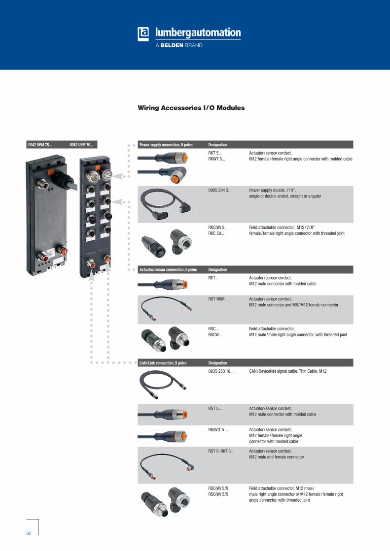
60
Wiring Accessories I/O Modules
Power supply connection, 5 poles Designation
RKT 5... Actuator /sensor cordset, RKWT 5... M12 female/ female right angle connector with molded cable
0905 204 3... Power supply double, 7/8",single or double ended, straight or angular
RKC(W) 5... Field attachable connector, M12/ 7/8"RKC 50... female/ female right angle connector with threaded joint
0942 UEM 78... 0942 UEM 70...
Actuator/sensor connection, 5 poles Designation
RST... Actuator /sensor cordset, M12 male connector with molded cable
RST-RKM... Actuator /sensor cordset, M12 male connector and M8/ M12 female connector
RSC... Field attachable connector, RSCW... M12 male/male right angle connector, with threaded joint
LioN-Link connection, 5 poles Designation
0935 253 10... CAN/DeviceNet signal cable, Thin Cable, M12
RST 5 ... Actuator /sensor cordset, M12 male connector with molded cable
RK(W)T 5 ... Actuator /sensor cordset, M12 female/ female right angle connector with molded cable
RST 5-RKT 5 ... Actuator /sensor cordset, M12 male and female connector
RSC(W) 5/9 Field attachable connector , M12 male/RSC(W) 5/9 male right angle connector or M12 female/ female right
angle connector, with threaded joint
RZ_LioN-Link_Brochure_GB:LioN-Link 12.04.2010 12:57 Uhr Seite 60

61
LioN-Link Configurator for Intermediate Supply
We provide a free calculation program to assist you in designing your LioN-Link network. This allows you to plan the necessary intermediate supplies accurately and select their optimumlocation within the network.
The table takes the following conditions into account:Calculation of the voltage drop (in volts and percent) for each cable section betweenthe designed Link modules of a Link branch, taking into account- the Link cable length- the Link cable cross section- the Link module type- the channel current load- the module resultant current- the total resultant current- the Link connector M12
The program and instructions are available from the download portal at www.beldensolutions.com
RZ_LioN-Link_Brochure_GB:LioN-Link 12.04.2010 12:57 Uhr Seite 61

62
Index
Designation Order number Page
0940 CSL 601 89975 20
0940 DSL 601 89974 22
0940 ESL 601 105689 24
0940 PSL 601 87058 14
0940 PSL 602 106172 16
0940 PSL 603 104873 18
0942 UEM 600 92356 30
0942 UEM 601 93201 32
0942 UEM 602 108105 48
0942 UEM 612 108106 50
0942 UEM 620 108053 42
0942 UEM 630 102076 34
0942 UEM 631 102080 36
0942 UEM 650 87040 26
0942 UEM 651 87043 28
0942 UEM 670 104872 40
0942 UEM 700 93199 44
0942 UEM 701 93198 46
0942 UEM 780/5 M 105165 52
0942 UEM 782/1 M 102840 54
0942 UEM 783 102163 38
0941 UNC 601/10 M 96720 56
Order number Designation Page
87040 0942 UEM 650 26
87043 0942 UEM 651 28
87058 0940 PSL 601 14
89974 0940 DSL 601 22
89975 0940 CSL 601 20
92356 0942 UEM 600 30
93198 0942 UEM 701 46
93199 0942 UEM 700 44
93201 0942 UEM 601 32
96720 0941 UNC 601/10 M 56
102076 0942 UEM 630 34
102080 0942 UEM 631 36
102163 0942 UEM 783 38
102840 0942 UEM 782/1 M 54
104872 0942 UEM 670 40
104873 0940 PSL 603 18
105165 0942 UEM 780/5 M 52
105689 0940 ESL 601 24
106172 0940 PSL 602 16
108053 0942 UEM 620 42
108105 0942 UEM 602 48
108106 0942 UEM 612 50
Index by designation
Index by order number
RZ_LioN-Link_Brochure_GB:LioN-Link 12.04.2010 12:57 Uhr Seite 62

63
General Technical Information
Important note
As a customer, you can expect our products to be in compliance with the latest technical standards. We therefore reserve the right to make design changes that may result in differences from the documented technical data.
If you have any special requirements or specifications, please consult our sales team. Our currentterms and conditions of sale can be found on the Internet at www.beldensolutions.com
UL approved
Highly resistant to oils, coolants, lubricants and emulsions
Highly resistant to vibrations and shocks
Explanation of product features
��
RZ_LioN-Link_Brochure_GB:LioN-Link 12.04.2010 12:57 Uhr Seite 63

Optimization of FieldWiring Through the Utilization of a Modular IP 67 Fieldbus Solution
LioN-LinkThe Modular, Fieldbus Independent I/O System
Lio
N-L
ink – T
he M
odula
r, Fie
ldbus In
dependent I/O
Syste
m
GLOBAL LOCATIONS
CONTACT FOR LUMBERGAUTOMATIONTM BRAND
Im Gewerbepark 258579 SchalksmühleGermanyPhone: +49-2355-5044-000Fax: [email protected]
CONTACT FORHIRSCHMANNTM BRAND
Stuttgarter Straße 45-5172654 NeckartenzlingenGermanyPhone: +49-7127-14-0Fax: [email protected]
CONTACT FOR BELDEN® BRAND
Edisonstraat 95928 PG VenloThe NetherlandsPhone: +31-77-3878-555Fax: [email protected]
©Copyright 2010, Belden Inc.
Printed in Germany
DS 280 720-884 04.2010
For worldwide sales and technical support, visit us at: www.lumberg-automation.com
www.beldensolutions.com
RZ_LioN-Link_Brochure_Umschlag-komplett_GB 12.04.2010 13:01 Uhr Seite 1