Ryobi MANUAL Weedwcker
17
FOR QUESTIONS, CALL 1-800-345-8746 in U.S. or 1-800-265-6778 in CANADA www.ryobi.com OPERATOR’S MANUAL Electric Trimmers 105r, 132r, & 137r
-
Upload
insipidonyx -
Category
Documents
-
view
233 -
download
0
Transcript of Ryobi MANUAL Weedwcker

8/4/2019 Ryobi MANUAL Weedwcker
http://slidepdf.com/reader/full/ryobi-manual-weedwcker 1/16
FOR QUESTIONS, CALL 1-800-345-8746 in U.S. or
1-800-265-6778 in CANADAwww.ryobi.com
IMPORTANT MANUAL DO NOT THROW AWAY
OPERATOR’S MANUAL
Electric Trimmers
105r, 132r, & 137r
8/4/2019 Ryobi MANUAL Weedwcker
http://slidepdf.com/reader/full/ryobi-manual-weedwcker 2/16
INTRODUCTION
2
TABLE OF CONTENTS
THANK YOU
Thank you for purchasing this quality product.This modern outdoor power tool is designed to
provide many hours of useful service. You willfind it to be a great labor-saving device.
This operator’s manual provides you with easy-to-understand operating instructions. Read theentire manual and follow all of the instructionsto keep your new outdoor power tool in topoperating condition.
The other manual that came with your powertool, the parts manual, contains all of theinformation that you need to order parts.
PRODUCT REFERENCES, ILLUSTRATIONS AND SPECIFICATIONS
All information, illustrations and specificationsin this manual are based on the latest productinformation available at the time of printing. Wereserve the right to make changes at any timewithout notice.
Copyright © 1998 Ryobi Outdoor Products, Inc. All Rights Reserved.
Click-Link® is a registered trademark of Ryobi
Outdoor Products, Inc.SpeedSpool® is a registered trademark of RyobiOutdoor Products, Inc.
NOTE: PROOF OF PURCHASE WILL BEREQUIRED FOR WARRANTY SERVICE.
I. Safety Warnings . . . . . . . . . . . . . . . . . . .3-6 A. Safety and International Symbols . . . . .6
II. Assembly Instructions . . . . . . . . . . . . . . .7-8 A. Installing the D-Handle . . . . . . . . . . . . .7B. Adjusting the D-Handle . . . . . . . . . . . . .7C. Installing the String Guard
Models 105r and 132r . . . . . . . . . . . . . .7D. Installing the String Guard
Model 137r . . . . . . . . . . . . . . . . . . . . . .8
III. Operating Instructions . . . . . . . . . . . . .8-10 A. Connecting the cord . . . . . . . . . . . . . . .8B. Starting the trimmer . . . . . . . . . . . . . . . .8C. Holding the trimmer . . . . . . . . . . . . . . . .8D. Operating two-speed switch
Models 132r and 137r . . . . . . . . . . . . . .9E. Operating the Click-Link System . . . . . .9F. Adjusting the trimming line length . . . . .10G. Decorative trimming . . . . . . . . . . . . . .10
IV. Maintenance and Repair Instructions .11-14 A. Line installation . . . . . . . . . . . . . . . . . .11B. Winding the existing reel . . . . . . . . . . .11C. Cleaning the SpeedSpool® . . . . . . . . .12D. Installing a prewound reel . . . . . . . . . .13E. Cleaning the trimmer . . . . . . . . . . . . . .14
V. Specifications . . . . . . . . . . . . . . . . . . . . .14
VI. Troubleshooting . . . . . . . . . . . . . . . . . . . .14
VII. Notes . . . . . . . . . . . . . . . . . . . . . . . . . . . .15
VIII. Warranty . . . . . . . . . . . . . . . . . . . . . . . . .16
Make sure this manual is carefully read andunderstood before starting or operating thisequipment.
CONTENTS OF CARTON
This carton includes the following:
1. For completely assembled models:
• Trimmer
• Operator’s manual
• Owner’s registration card2. For unassembled models - hardware pack
containing:
• D-Handle and hardware
• String guard and screws
• Operator's manual
• Owner’s registration card
THIS PRODUCT IS COVERED BY ONE OR MORE OFTHE US PATENTS: 5,076,149; 4,779,405; 4,651,422;4,505,040; 4,463,498; 4,369,742; 4,342,236; 4,223,441;
2,125,688; D-249,012; D-239,329; OTHER PATENTSPENDING.
SERVICE INFORMATION
Service on this unit both within and after thewarranty period should be performed only byan authorized and approved service dealer.
Dial 1-800-345-8746 in the United States and1-800-265-6778 in Canada to obtain a listingof the authorized service dealer nearest you.
Do not return the unit to the retailer.
8/4/2019 Ryobi MANUAL Weedwcker
http://slidepdf.com/reader/full/ryobi-manual-weedwcker 3/16
3
SAFETY WARNINGS
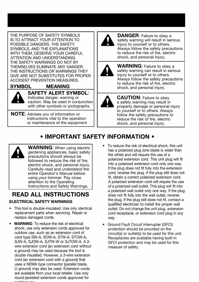
• To reduce the risk of electrical shock, this unithas a polarized plug (one blade is wider thanthe other) and will require the use of apolarized extension cord. This unit plug will fitinto a polarized extension cord only one way.If the plug does not fit fully into the extensioncord, reverse the plug. If the plug still does notfit, obtain a correct polarized extension cord. A polarized extension cord will require the useof a polarized wall outlet. This plug will fit intoa polarized wall outlet only one way. If the plugdoes not fit fully into the wall outlet, reversethe plug. If the plug still does not fit, contact aqualified electrician to install the proper walloutlet. Do not change the unit plug, extensioncord receptacle, or extension cord plug in anyway.
• Ground Fault Circuit Interrupter (GFCI)protection should be provided on thecircuit(s) or outlet(s) to be used for this unit.Receptacles are available having built-inGFCI protection and may be used for this
measure of safety.
ELECTRICAL SAFETY WARNINGS
• This tool is double-insulated. Use only identicalreplacement parts when servicing. Repair orreplace damaged cords.
• WARNING: To reduce the risk of electricalshock, use only extension cords approved foroutdoor use, such as an extension cord ofcord type SW-A, SOW-A, STW-A, STOW-A,SJW-A, SJOW-A, SJTW-W or SJTOW-A. A 2-
wire extension cord (an extension cord withouta ground) may be used because the tool isdouble insulated. However, a 3-wire extensioncord (an extension cord with a ground) thatuses a NEMA type connector (parallel blade,U ground) may also be used. Extension cordsare available from your local retailer. Use onlyround-jacketed extension cords approved foroutdoor use.
THE PURPOSE OF SAFETY SYMBOLSIS TO ATTRACT YOUR ATTENTION TOPOSSIBLE DANGERS. THE SAFETY
SYMBOLS, AND THE EXPLANATIONSWITH THEM, DESERVE YOUR CAREFUL ATTENTION AND UNDERSTANDING.THE SAFETY WARNINGS DO NOT BYTHEMSELVES ELIMINATE ANY DANGER.THE INSTRUCTIONS OR WARNINGS THEYGIVE ARE NOT SUBSTITUTES FOR PROPER ACCIDENT PREVENTION MEASURES.
SYMBOL MEANING
DANGER: Failure to obey asafety warning will result in seriousinjury to yourself or to others.
Always follow the safety precautionsto reduce the risk of fire, electricshock, and personal injury.
SAFETY ALERT SYMBOL:
Indicates danger, warning orcaution. May be used in conjunctionwith other symbols or pictographs.
WARNING: Failure to obey asafety warning can result in seriousinjury to yourself or to others. Always follow the safety precautionsto reduce the risk of fire, electricshock, and personal injury.
WARNING: When using electricgardening appliances, basic safetyprecautions should always befollowed to reduce the risk of fire,electric shock, and personal injury.Carefully read and understand theentire Operator's Manual beforeusing your trimmer. Pay closeattention to the OperatingInstructions and Safety Warnings.
CAUTION: Failure to obeya safety warning may result inproperty damage or personal injuryto yourself or to others. Alwaysfollow the safety precautions toreduce the risk of fire, electricshock, and personal injury.
NOTE: Advises you of information orinstructions vital to the operationor maintenance of the equipment.
• IMPORTANT SAFETY INFORMATION •
READ ALL INSTRUCTIONS
8/4/2019 Ryobi MANUAL Weedwcker
http://slidepdf.com/reader/full/ryobi-manual-weedwcker 4/16
SAFETY WARNINGS
4
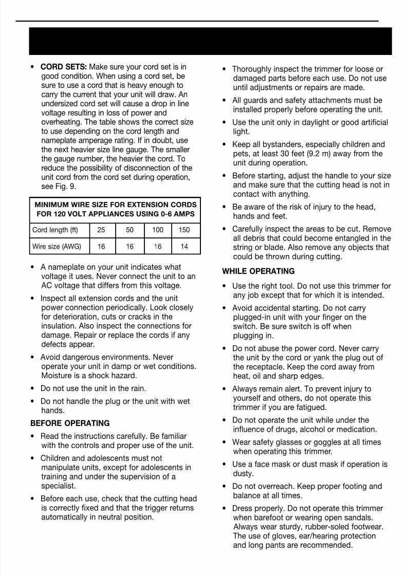
• Thoroughly inspect the trimmer for loose ordamaged parts before each use. Do not useuntil adjustments or repairs are made.
• All guards and safety attachments must beinstalled properly before operating the unit.
• Use the unit only in daylight or good artificiallight.
• Keep all bystanders, especially children andpets, at least 30 feet (9.2 m) away from theunit during operation.
• Before starting, adjust the handle to your sizeand make sure that the cutting head is not incontact with anything.
• Be aware of the risk of injury to the head,hands and feet.
• Carefully inspect the areas to be cut. Removeall debris that could become entangled in thestring or blade. Also remove any objects thatcould be thrown during cutting.
WHILE OPERATING
• Use the right tool. Do not use this trimmer forany job except that for which it is intended.
• Avoid accidental starting. Do not carryplugged-in unit with your finger on theswitch. Be sure switch is off whenplugging in.
• Do not abuse the power cord. Never carrythe unit by the cord or yank the plug out ofthe receptacle. Keep the cord away fromheat, oil and sharp edges.
• Always remain alert. To prevent injury toyourself and others, do not operate thistrimmer if you are fatigued.
• Do not operate the unit while under theinfluence of drugs, alcohol or medication.
• Wear safety glasses or goggles at all timeswhen operating this trimmer.
• Use a face mask or dust mask if operation isdusty.
• Do not overreach. Keep proper footing andbalance at all times.
• Dress properly. Do not operate this trimmerwhen barefoot or wearing open sandals. Always wear sturdy, rubber-soled footwear.The use of gloves, ear/hearing protectionand long pants are recommended.
• A nameplate on your unit indicates whatvoltage it uses. Never connect the unit to an AC voltage that differs from this voltage.
• Inspect all extension cords and the unitpower connection periodically. Look closelyfor deterioration, cuts or cracks in theinsulation. Also inspect the connections fordamage. Repair or replace the cords if anydefects appear.
• Avoid dangerous environments. Neveroperate your unit in damp or wet conditions.Moisture is a shock hazard.
• Do not use the unit in the rain.
• Do not handle the plug or the unit with wethands.
BEFORE OPERATING
• Read the instructions carefully. Be familiarwith the controls and proper use of the unit.
• Children and adolescents must notmanipulate units, except for adolescents intraining and under the supervision of aspecialist.
• Before each use, check that the cutting headis correctly fixed and that the trigger returnsautomatically in neutral position.
• CORD SETS: Make sure your cord set is ingood condition. When using a cord set, besure to use a cord that is heavy enough tocarry the current that your unit will draw. An
undersized cord set will cause a drop in linevoltage resulting in loss of power andoverheating. The table shows the correct sizeto use depending on the cord length andnameplate amperage rating. If in doubt, usethe next heavier size line gauge. The smallerthe gauge number, the heavier the cord. Toreduce the possibility of disconnection of theunit cord from the cord set during operation,see Fig. 9.
MINIMUM WIRE SIZE FOR EXTENSION CORDS
FOR 120 VOLT APPLIANCES USING 0-6 AMPS
Cord length (ft) 25 50 100 150
Wire size (AWG) 16 16 16 14
8/4/2019 Ryobi MANUAL Weedwcker
http://slidepdf.com/reader/full/ryobi-manual-weedwcker 5/16
5
SAFETY WARNINGS
• Do not wear loose fitting clothing or articlessuch as scarves, strings, chains, ties, etc.,because they could get caught in movingparts. Also make sure long hair does not getcaught in moving parts. Long hair must bepulled back and secured off shoulders andneck.
• Keep hands, face, and feet away from allmoving parts. Do not attempt to touch orstop the string when it is rotating.
• Always hold the trimmer with both handswhen operating. Keep a firm grip on boththe front and rear handles or grips.
• Frequently inspect the condition of thecutting head. All damaged parts must bereplaced immediately. Follow all the requiredprecautions when undertaking replacement.
• If you strike or become entangled with aforeign object, stop the engine immediatelyand check for damage. Repair any damagebefore further operation is attempted. Donot operate the trimmer with loose ordamaged parts.
• Do not operate the unit faster than the speednecessary to cut, trim or edge. Do not runthe unit at high speed when not cutting.
• Do not force the unit. It will do the job betterand with less likelihood of a risk of injury atthe rate for which it was designed.
• The string guard must be in place at alltimes while operating the trimmer. Failureto use the string guard may cause the unitto overheat. DO NOT OPERATE WITHOUTTHE GUARD IN PLACE.
• Do not extend the trimming line beyond thelength of the guard specified in this manual.
• Do not operate trimmer without bothtrimming lines extended, and the properline installed.
• Never use metal-reinforced or monofilamentline that is not specifically designed for usewith your model.
• Keep trimmer clean of vegetation and other
materials.
• Always stop the unit when cutting is delayedor when walking from one cutting locationto another.
• All interventions, whether for maintenance,repair or for changing cutting head or safetyattachments, must be undertaken with theunit disconnected from the power supply.
• Use only genuine replacement parts whenservicing this trimmer. These parts areavailable from your authorized dealer.The use of non-standard parts, or otheraccessories or attachments not designed forthis trimmer, could result in serious injury tothe user or damage to the trimmer and void
your warranty.
OTHER SAFETY WARNINGS
• Disconnect the unit from the power supplywhen not in use, before servicing, whenchanging accessories such as cutting head,and the like.
• Maintain trimmer with care. Keep the unitclean and serviced for the best and safestperformance. Follow the maintenance
instructions. Always use a clean cloth whencleaning. Never use strong detergents,gasoline, petroleum-based products, or anystrong solvents to clean the unit.
• Keep your unit in good working condition.Follow instructions for servicing andchanging accessories. Inspect unitperiodically, and if damaged, have it repairedby an authorized service facility. Inspectextension cords periodically and replace ifdamaged. Keep handles dry, clean, and freefrom oil and grease.
• Store unit indoors. When not in use,appliances should be stored indoors in a dry,and high or locked-up place, out of the reachof children.
• Keep these instructions. Refer to themfrequently and use them to instruct otherusers. If you loan someone this unit, alsoloan them these instructions.
SAVE THESE INSTRUCTIONS
8/4/2019 Ryobi MANUAL Weedwcker
http://slidepdf.com/reader/full/ryobi-manual-weedwcker 6/16
6
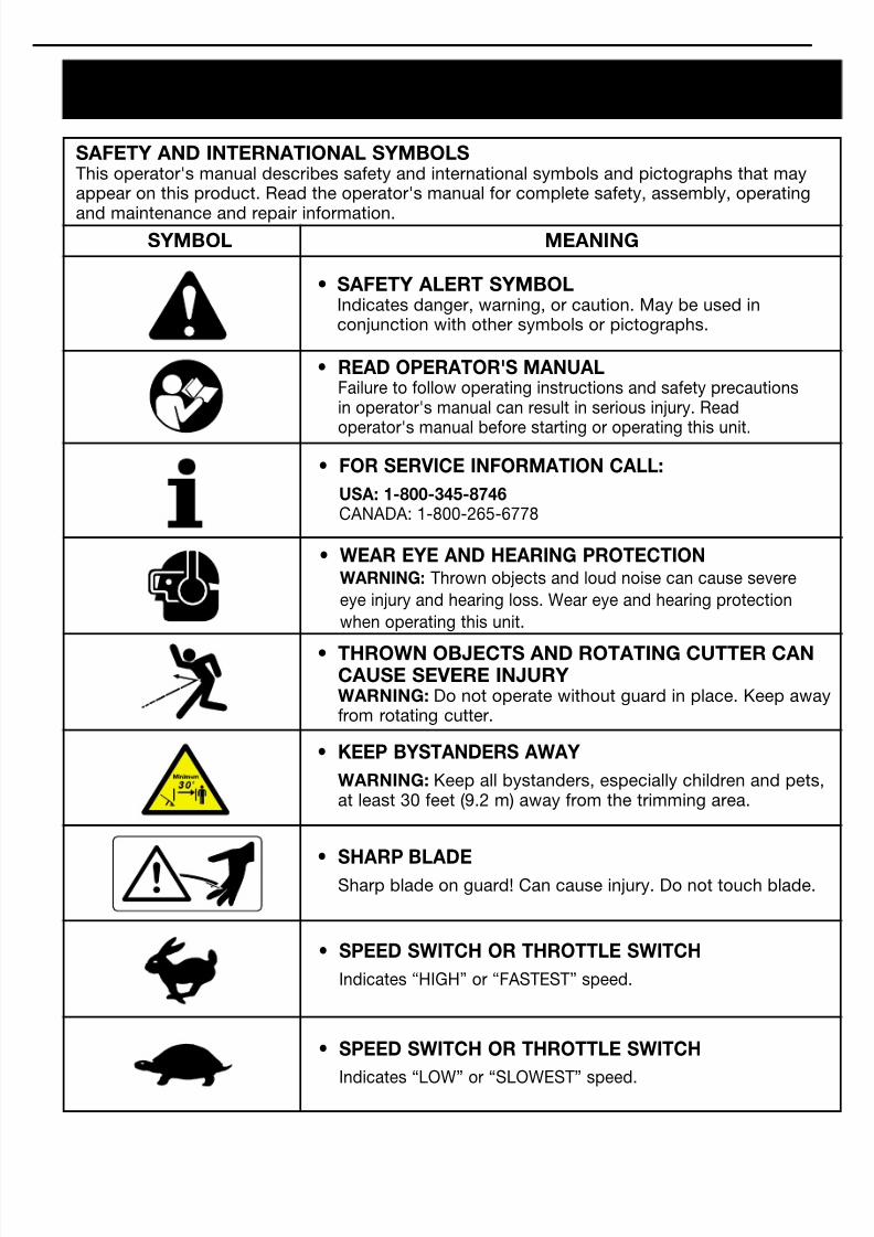
SAFETY AND INTERNATIONAL SYMBOLSThis operator's manual describes safety and international symbols and pictographs that mayappear on this product. Read the operator's manual for complete safety, assembly, operating
and maintenance and repair information.SYMBOL MEANING
• SAFETY ALERT SYMBOLIndicates danger, warning, or caution. May be used inconjunction with other symbols or pictographs.
• READ OPERATOR'S MANUALFailure to follow operating instructions and safety precautionsin operator's manual can result in serious injury. Read
operator's manual before starting or operating this unit.
• THROWN OBJECTS AND ROTATING CUTTER CANCAUSE SEVERE INJURYWARNING: Do not operate without guard in place. Keep awayfrom rotating cutter.
• WEAR EYE AND HEARING PROTECTIONWARNING: Thrown objects and loud noise can cause severe
eye injury and hearing loss. Wear eye and hearing protection
when operating this unit.
• FOR SERVICE INFORMATION CALL:
USA: 1-800-345-8746CANADA: 1-800-265-6778
• SPEED SWITCH OR THROTTLE SWITCH
Indicates “HIGH” or “FASTEST” speed.
• SPEED SWITCH OR THROTTLE SWITCH
Indicates “LOW” or “SLOWEST” speed.
• KEEP BYSTANDERS AWAY
WARNING: Keep all bystanders, especially children and pets,at least 30 feet (9.2 m) away from the trimming area.
• SHARP BLADESharp blade on guard! Can cause injury. Do not touch blade.
SAFETY WARNINGS
8/4/2019 Ryobi MANUAL Weedwcker
http://slidepdf.com/reader/full/ryobi-manual-weedwcker 7/16
7
ASSEMBLY INSTRUCTIONS
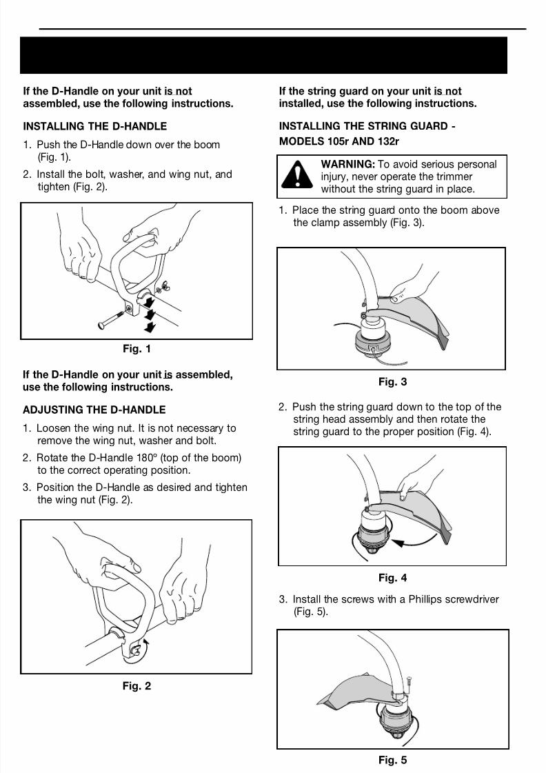
If the D-Handle on your unit is notassembled, use the following instructions.
INSTALLING THE D-HANDLE
1. Push the D-Handle down over the boom(Fig. 1).
2. Install the bolt, washer, and wing nut, andtighten (Fig. 2).
Fig. 1
Fig. 2
If the D-Handle on your unit is assembled,use the following instructions.
ADJUSTING THE D-HANDLE
1. Loosen the wing nut. It is not necessary toremove the wing nut, washer and bolt.
2. Rotate the D-Handle 180º (top of the boom)to the correct operating position.
3. Position the D-Handle as desired and tightenthe wing nut (Fig. 2).
If the string guard on your unit is notinstalled, use the following instructions.
INSTALLING THE STRING GUARD -
MODELS 105r AND 132r
WARNING: To avoid serious personalinjury, never operate the trimmerwithout the string guard in place.
Fig. 3
1. Place the string guard onto the boom abovethe clamp assembly (Fig. 3).
2. Push the string guard down to the top of thestring head assembly and then rotate thestring guard to the proper position (Fig. 4).
Fig. 4
3. Install the screws with a Phillips screwdriver(Fig. 5).
Fig. 5
8/4/2019 Ryobi MANUAL Weedwcker
http://slidepdf.com/reader/full/ryobi-manual-weedwcker 8/16
8
ASSEMBLY INSTRUCTIONS
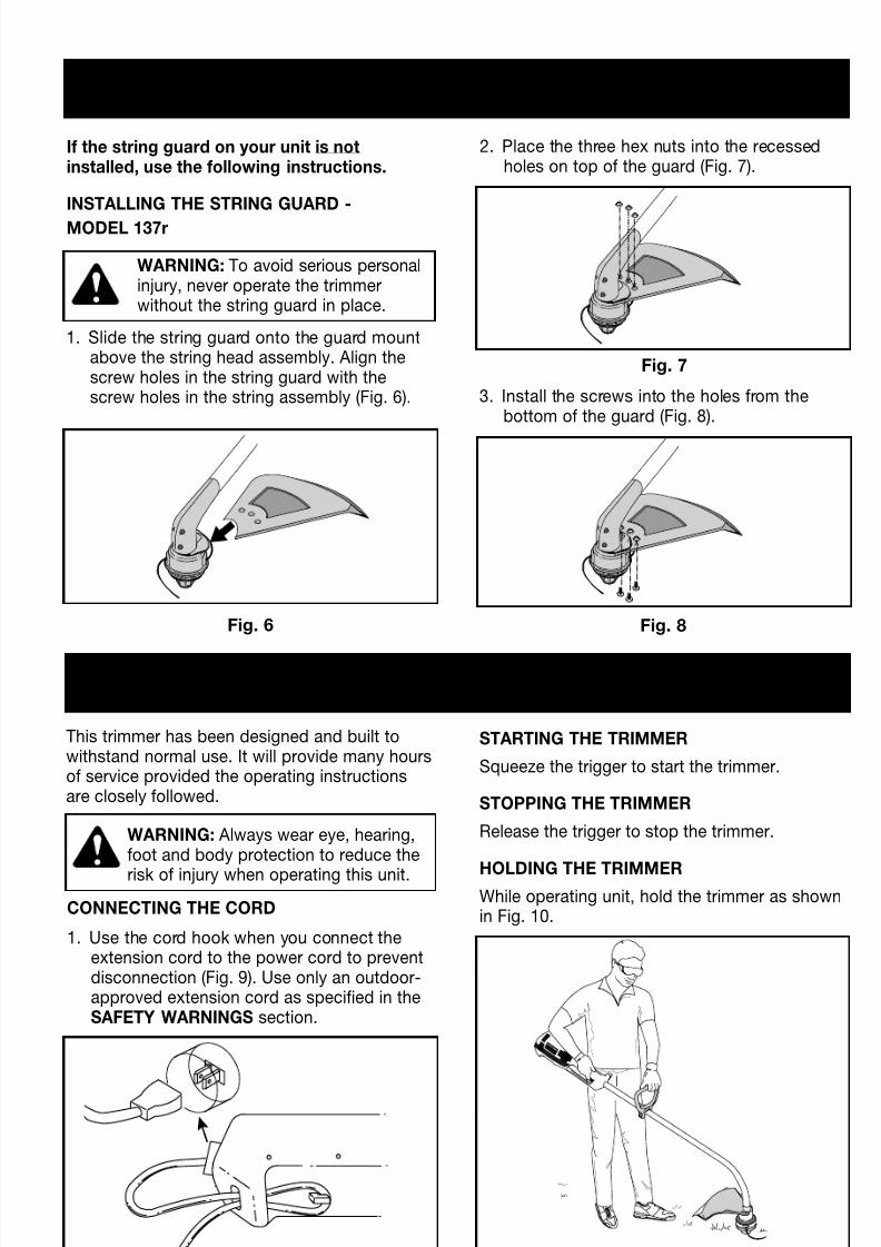
If the string guard on your unit is notinstalled, use the following instructions.
INSTALLING THE STRING GUARD -
MODEL 137r
WARNING: To avoid serious personalinjury, never operate the trimmerwithout the string guard in place.
Fig. 6
1. Slide the string guard onto the guard mountabove the string head assembly. Align thescrew holes in the string guard with thescrew holes in the string assembly (Fig. 6).
2. Place the three hex nuts into the recessedholes on top of the guard (Fig. 7).
Fig. 7
3. Install the screws into the holes from thebottom of the guard (Fig. 8).
Fig. 8
OPERATING INSTRUCTIONS
This trimmer has been designed and built towithstand normal use. It will provide many hoursof service provided the operating instructionsare closely followed.
WARNING: Always wear eye, hearing,foot and body protection to reduce the
risk of injury when operating this unit.
CONNECTING THE CORD
1. Use the cord hook when you connect theextension cord to the power cord to preventdisconnection (Fig. 9). Use only an outdoor-approved extension cord as specified in theSAFETY WARNINGS section.
Fig. 9
STARTING THE TRIMMER
Squeeze the trigger to start the trimmer.
STOPPING THE TRIMMER
Release the trigger to stop the trimmer.
HOLDING THE TRIMMERWhile operating unit, hold the trimmer as shownin Fig. 10.
Fig. 10
8/4/2019 Ryobi MANUAL Weedwcker
http://slidepdf.com/reader/full/ryobi-manual-weedwcker 9/16
9
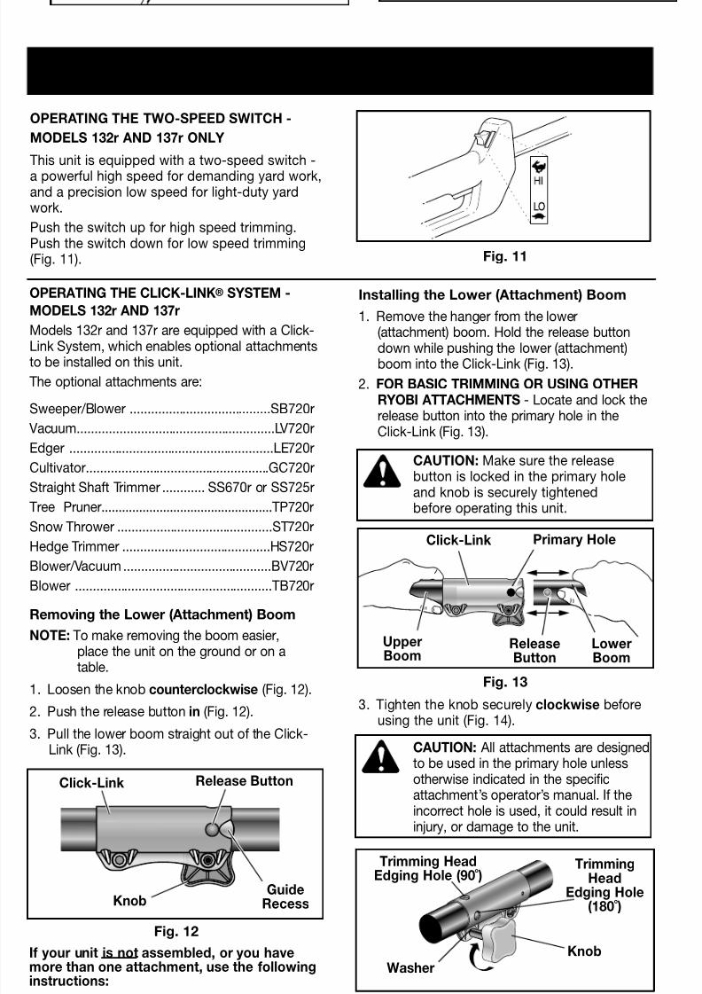
OPERATING THE CLICK-LINK® SYSTEM -
MODELS 132r AND 137r
Models 132r and 137r are equipped with a Click-
Link System, which enables optional attachmentsto be installed on this unit.
The optional attachments are:
Sweeper/Blower ........................................SB720r
Vacuum........................................................LV720r
Edger ..........................................................LE720r
Cultivator....................................................GC720r
Straight Shaft Trimmer ............ SS670r or SS725r
Tree Pruner..................................................TP720r
Snow Thrower ............................................ST720r
Hedge Trimmer ..........................................HS720r
Blower/Vacuum..........................................BV720r
Blower ........................................................TB720r
Removing the Lower (Attachment) Boom
NOTE: To make removing the boom easier,place the unit on the ground or on atable.
1. Loosen the knob counterclockwise (Fig. 12).2. Push the release button in (Fig. 12).
3. Pull the lower boom straight out of the Click-Link (Fig. 13).
CAUTION: Make sure the releasebutton is locked in the primary holeand knob is securely tightenedbefore operating this unit.
CAUTION: All attachments are designedto be used in the primary hole unlessotherwise indicated in the specificattachment’s operator’s manual. If theincorrect hole is used, it could result ininjury, or damage to the unit.
Click-Link
Click-Link
Release Button
GuideRecessKnob
Primary Hole
UpperBoom
LowerBoom
ReleaseButton
3. Tighten the knob securely clockwise beforeusing the unit (Fig. 14).
OPERATING INSTRUCTIONS
Fig. 11
OPERATING THE TWO-SPEED SWITCH -
MODELS 132r AND 137r ONLY
This unit is equipped with a two-speed switch -
a powerful high speed for demanding yard work,and a precision low speed for light-duty yardwork.
Push the switch up for high speed trimming.Push the switch down for low speed trimming(Fig. 11).
Installing the Lower (Attachment) Boom
1. Remove the hanger from the lower(attachment) boom. Hold the release button
down while pushing the lower (attachment)boom into the Click-Link (Fig. 13).
2. FOR BASIC TRIMMING OR USING OTHERRYOBI ATTACHMENTS - Locate and lock therelease button into the primary hole in theClick-Link (Fig. 13).
Fig. 12
Fig. 13
Fig. 14
If your unit is not assembled, or you havemore than one attachment, use the followinginstructions:
Trimming HeadEdging Hole (90 ̊) TrimmingHead
Edging Hole(180 ̊)
Knob
Washer
8/4/2019 Ryobi MANUAL Weedwcker
http://slidepdf.com/reader/full/ryobi-manual-weedwcker 10/16
10
OPERATING INSTRUCTIONS
Fig. 15a
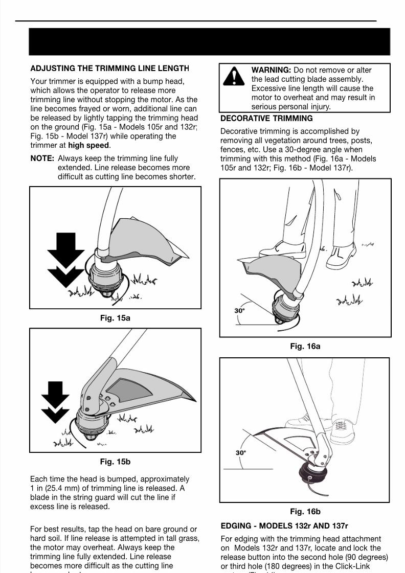
ADJUSTING THE TRIMMING LINE LENGTH
Your trimmer is equipped with a bump head,which allows the operator to release more
trimming line without stopping the motor. As theline becomes frayed or worn, additional line canbe released by lightly tapping the trimming headon the ground (Fig. 15a - Models 105r and 132r;Fig. 15b - Model 137r) while operating thetrimmer at high speed.
NOTE: Always keep the trimming line fullyextended. Line release becomes moredifficult as cutting line becomes shorter.
Fig. 15b
Each time the head is bumped, approximately1 in (25.4 mm) of trimming line is released. Ablade in the string guard will cut the line ifexcess line is released.
For best results, tap the head on bare ground orhard soil. If line release is attempted in tall grass,the motor may overheat. Always keep thetrimming line fully extended. Line releasebecomes more difficult as the cutting linebecomes shorter.
Fig. 16a
Fig. 16b
WARNING: Do not remove or alterthe lead cutting blade assembly.Excessive line length will cause the
motor to overheat and may result inserious personal injury.
DECORATIVE TRIMMING
Decorative trimming is accomplished byremoving all vegetation around trees, posts,fences, etc. Use a 30-degree angle whentrimming with this method (Fig. 16a - Models105r and 132r; Fig. 16b - Model 137r).
EDGING - MODELS 132r AND 137r
For edging with the trimming head attachmenton Models 132r and 137r, locate and lock therelease button into the second hole (90 degrees)or third hole (180 degrees) in the Click-Linksystem (Fig. 14).
8/4/2019 Ryobi MANUAL Weedwcker
http://slidepdf.com/reader/full/ryobi-manual-weedwcker 11/16
11
MAINTENANCE AND REPAIR INSTRUCTIONS
Fig. 17
Fig. 18
Fig. 19
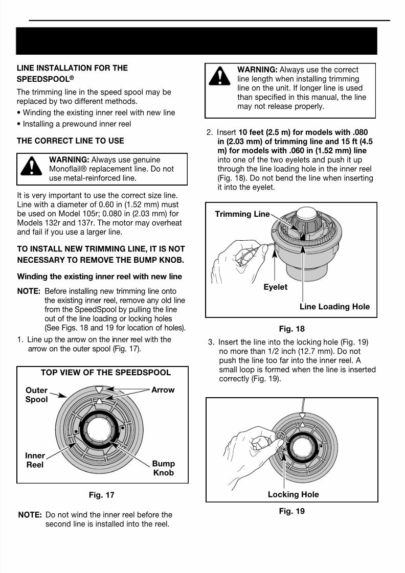
LINE INSTALLATION FOR THE
SPEEDSPOOL®
The trimming line in the speed spool may be
replaced by two different methods.• Winding the existing inner reel with new line
• Installing a prewound inner reel
THE CORRECT LINE TO USE
WARNING: Always use genuineMonoflail® replacement line. Do notuse metal-reinforced line.
It is very important to use the correct size line.Line with a diameter of 0.60 in (1.52 mm) mustbe used on Model 105r; 0.080 in (2.03 mm) forModels 132r and 137r. The motor may overheatand fail if you use a larger line.
TO INSTALL NEW TRIMMING LINE, IT IS NOT
NECESSARY TO REMOVE THE BUMP KNOB.
Winding the existing inner reel with new line
NOTE: Before installing new trimming line onto
the existing inner reel, remove any old linefrom the SpeedSpool by pulling the lineout of the line loading or locking holes(See Figs. 18 and 19 for location of holes).
1. Line up the arrow on the inner reel with thearrow on the outer spool (Fig. 17).
NOTE: Do not wind the inner reel before thesecond line is installed into the reel.
WARNING: Always use the correctline length when installing trimmingline on the unit. If longer line is used
than specified in this manual, the linemay not release properly.
2. Insert 10 feet (2.5 m) for models with .080in (2.03 mm) of trimming line and 15 ft (4.5m) for models with .060 in (1.52 mm) lineinto one of the two eyelets and push it upthrough the line loading hole in the inner reel(Fig. 18). Do not bend the line when insertingit into the eyelet.
3. Insert the line into the locking hole (Fig. 19)no more than 1/2 inch (12.7 mm). Do notpush the line too far into the inner reel. Asmall loop is formed when the line is insertedcorrectly (Fig. 19).
TOP VIEW OF THE SPEEDSPOOL
Outer
Spool
Arrow
InnerReel Bump
Knob
Trimming Line
Line Loading Hole
Eyelet
Locking Hole
8/4/2019 Ryobi MANUAL Weedwcker
http://slidepdf.com/reader/full/ryobi-manual-weedwcker 12/16
12
MAINTENANCE AND REPAIR INSTRUCTIONS
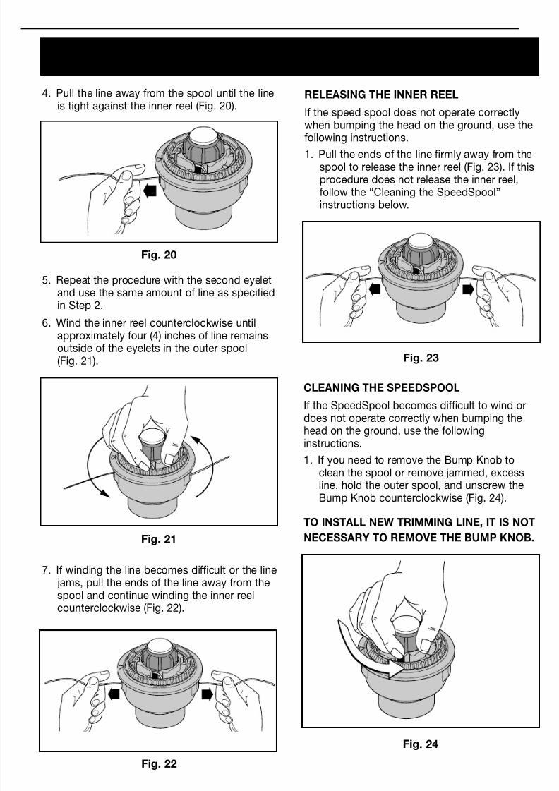
4. Pull the line away from the spool until the lineis tight against the inner reel (Fig. 20).
Fig. 20
Fig. 22
Fig. 24
Fig. 23
Fig. 21
5. Repeat the procedure with the second eyeletand use the same amount of line as specifiedin Step 2.
6. Wind the inner reel counterclockwise untilapproximately four (4) inches of line remainsoutside of the eyelets in the outer spool(Fig. 21).
7. If winding the line becomes difficult or the line jams, pull the ends of the line away from thespool and continue winding the inner reelcounterclockwise (Fig. 22).
RELEASING THE INNER REEL
If the speed spool does not operate correctlywhen bumping the head on the ground, use the
following instructions.1. Pull the ends of the line firmly away from the
spool to release the inner reel (Fig. 23). If thisprocedure does not release the inner reel,follow the “Cleaning the SpeedSpool”instructions below.
CLEANING THE SPEEDSPOOL
If the SpeedSpool becomes difficult to wind or
does not operate correctly when bumping thehead on the ground, use the followinginstructions.
1. If you need to remove the Bump Knob toclean the spool or remove jammed, excessline, hold the outer spool, and unscrew theBump Knob counterclockwise (Fig. 24).
TO INSTALL NEW TRIMMING LINE, IT IS NOT
NECESSARY TO REMOVE THE BUMP KNOB.
8/4/2019 Ryobi MANUAL Weedwcker
http://slidepdf.com/reader/full/ryobi-manual-weedwcker 13/16
13
MAINTENANCE AND REPAIR INSTRUCTIONS
Fig. 28
Fig. 27
Fig. 26
Fig. 25
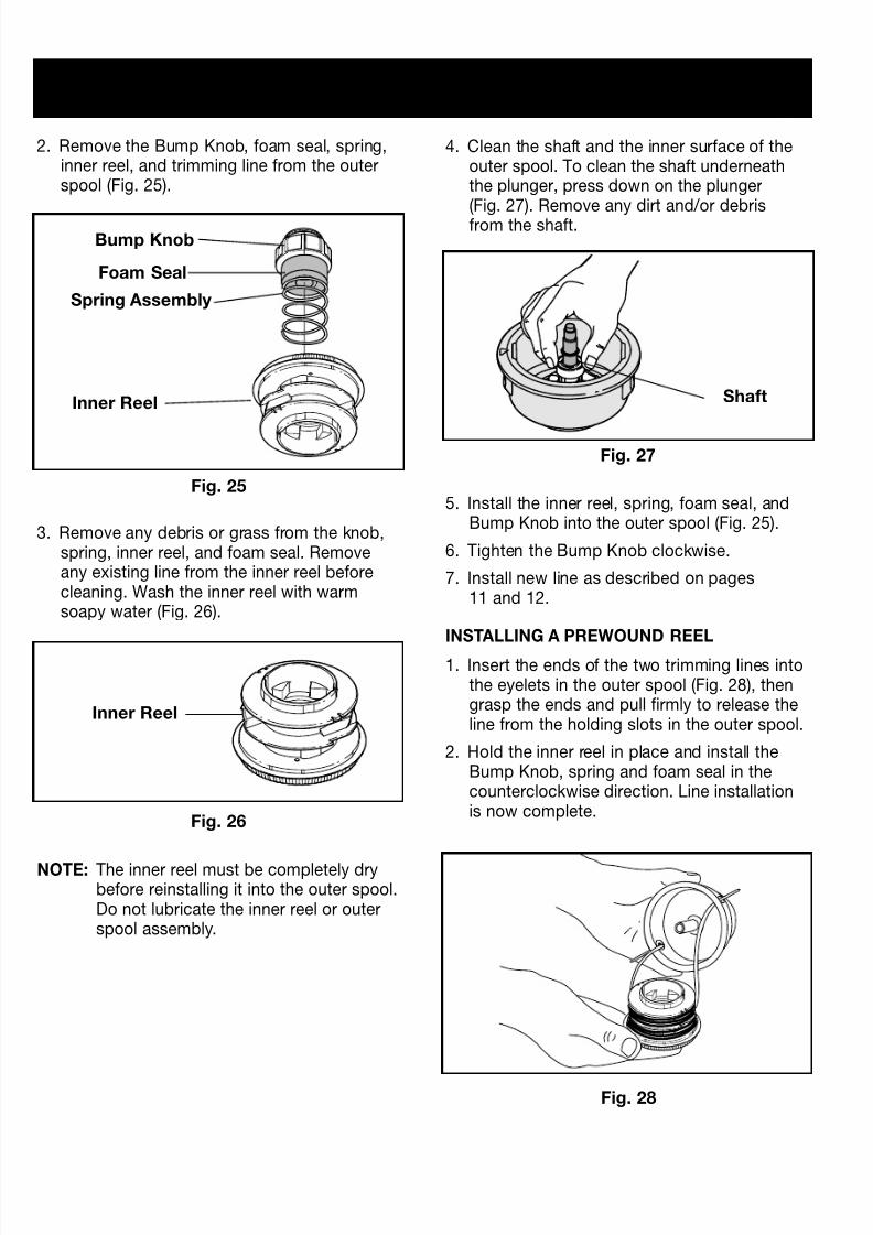
2. Remove the Bump Knob, foam seal, spring,inner reel, and trimming line from the outerspool (Fig. 25).
3. Remove any debris or grass from the knob,spring, inner reel, and foam seal. Removeany existing line from the inner reel beforecleaning. Wash the inner reel with warmsoapy water (Fig. 26).
NOTE: The inner reel must be completely drybefore reinstalling it into the outer spool.Do not lubricate the inner reel or outerspool assembly.
4. Clean the shaft and the inner surface of theouter spool. To clean the shaft underneaththe plunger, press down on the plunger(Fig. 27). Remove any dirt and/or debrisfrom the shaft.
5. Install the inner reel, spring, foam seal, andBump Knob into the outer spool (Fig. 25).
6. Tighten the Bump Knob clockwise.
7. Install new line as described on pages11 and 12.
INSTALLING A PREWOUND REEL
1. Insert the ends of the two trimming lines intothe eyelets in the outer spool (Fig. 28), thengrasp the ends and pull firmly to release theline from the holding slots in the outer spool.
2. Hold the inner reel in place and install theBump Knob, spring and foam seal in thecounterclockwise direction. Line installationis now complete.
Bump Knob
Foam Seal
Spring Assembly
Inner Reel
Inner Reel
Shaft
8/4/2019 Ryobi MANUAL Weedwcker
http://slidepdf.com/reader/full/ryobi-manual-weedwcker 14/16
14
MAINTENANCE AND
REPAIR INSTRUCTIONS
SPECIFICATIONS
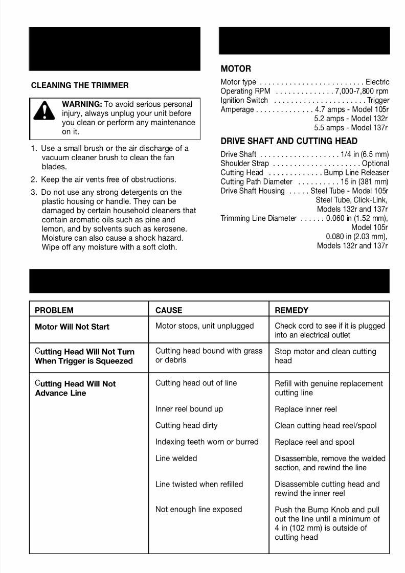
MOTOR
Motor type . . . . . . . . . . . . . . . . . . . . . . . . . ElectricOperating RPM . . . . . . . . . . . . . . 7,000-7,800 rpm
Ignition Switch . . . . . . . . . . . . . . . . . . . . . . Trigger Amperage . . . . . . . . . . . . . . 4.7 amps - Model 105r
5.2 amps - Model 132r5.5 amps - Model 137r
DRIVE SHAFT AND CUTTING HEAD
Drive Shaft . . . . . . . . . . . . . . . . . . . 1/4 in (6.5 mm)Shoulder Strap . . . . . . . . . . . . . . . . . . . . . OptionalCutting Head . . . . . . . . . . . . . Bump Line ReleaserCutting Path Diameter . . . . . . . . . . 15 in (381 mm)Drive Shaft Housing . . . . . Steel Tube - Model 105r
Steel Tube, Click-Link,Models 132r and 137r
Trimming Line Diameter . . . . . . 0.060 in (1.52 mm),Model 105r
0.080 in (2.03 mm),Models 132r and 137r
CLEANING THE TRIMMER
WARNING: To avoid serious personalinjury, always unplug your unit beforeyou clean or perform any maintenanceon it.
1. Use a small brush or the air discharge of avacuum cleaner brush to clean the fanblades.
2. Keep the air vents free of obstructions.
3. Do not use any strong detergents on the
plastic housing or handle. They can bedamaged by certain household cleaners thatcontain aromatic oils such as pine andlemon, and by solvents such as kerosene.Moisture can also cause a shock hazard.Wipe off any moisture with a soft cloth.
TROUBLESHOOTING
PROBLEM
Motor Will Not Start
Cutting Head Will Not TurnWhen Trigger is Squeezed
Cutting Head Will Not Advance Line
CAUSE
Motor stops, unit unplugged
Cutting head bound with grassor debris
Cutting head out of line
Inner reel bound up
Cutting head dirty
Indexing teeth worn or burred
Line welded
Line twisted when refilled
Not enough line exposed
REMEDY
Check cord to see if it is pluggedinto an electrical outlet
Stop motor and clean cuttinghead
Refill with genuine replacementcutting line
Replace inner reel
Clean cutting head reel/spool
Replace reel and spool
Disassemble, remove the weldedsection, and rewind the line
Disassemble cutting head andrewind the inner reel
Push the Bump Knob and pullout the line until a minimum of4 in (102 mm) is outside ofcutting head

8/4/2019 Ryobi MANUAL Weedwcker
http://slidepdf.com/reader/full/ryobi-manual-weedwcker 15/16
15
NOTES

8/4/2019 Ryobi MANUAL Weedwcker
http://slidepdf.com/reader/full/ryobi-manual-weedwcker 16/16
SAVE THESE INSTRUCTIONS FOR FUTURE REFERENCE.
FOR QUESTIONS CALL 1-800-345-8746 IN U.S.
OR 1-800-265-6778 IN CANADA
OPERATOR’S MANUAL PART NO. 181674 REV. B (51449)
PRINTED IN U.S.A. 10/98
RYOBI OUTDOOR PRODUCTS warrants each newRYOBI Product for two (2) years according to thefollowing terms.
This warranty extends to the original retailpurchaser only and commences on the date oforiginal retail purchase.
Any part of the RYOBI Product manufactured orsupplied by RYOBI and found in the reasonable
judgement of RYOBI to be defective in material orworkmanship will be repaired or replaced by anauthorized RYOBI service dealer without chargefor parts and labor.
The RYOBI Product including any defective partmust be returned to an authorized service dealerwithin the warranty period. The expense ofdelivering the RYOBI Product to the dealer forwarranty work and the expense of returning itback to the owner after repair or replacement will
be paid for by the owner. RYOBI’s responsibility inrespect to claims is limited to making the requiredrepairs or replacements and no claim of breach ofwarranty shall be cause for cancellation orrescission of the contract of sale of any RYOBIProduct. Proof of purchase will be required bythe dealer to substantiate any warranty claim. Allwarranty work must be performed by anauthorized RYOBI service dealer.
This warranty is limited to ninety (90) days from thedate of original retail purchase for any RYOBIProduct that is used for rental or commercialpurposes, or any other income-producing purpose.
This warranty does not cover any RYOBI Productthat has been subject to misuse, neglect,negligence, or accident, or that has beenoperated in any way contrary to the operatinginstructions as specified in the RYOBI Operator’sManual. This warranty does not apply to anydamage to the RYOBI Product that is the result ofimproper maintenance or to any RYOBI Productthat has been altered or modified so as toadversely affect the product's operation,performance or durability or that has beenaltered or modified so as to change its intendeduse. The warranty does not extend to repairs
made necessary by normal wear or by the use ofparts or accessories which are either incompatiblewith the RYOBI Product or adversely affect itsoperation, performance or durability.
RYOBI reserves the right to change or improvethe design of any RYOBI Product withoutassuming any obligation to modify any productpreviously manufactured.
ALL IMPLIED WARRANTIES ARE LIMITED INDURATION TO THE TWO (2) YEAR WARRANTYPERIOD OR NINETY (90) DAYS FOR PRODUCTSUSED FOR ANY COMMERCIAL PURPOSE.
ACCORDINGLY, ANY SUCH IMPLIEDWARRANTIES INCLUDING MERCHANTABILITY,FITNESS FOR A PARTICULAR PURPOSE, OR
OTHERWISE, ARE DISCLAIMED IN THEIRENTIRETY AFTER THE EXPIRATION OF THE APPROPRIATE TWO-YEAR OR NINETY DAYWARRANTY PERIOD. RYOBI’S OBLIGATIONUNDER THIS WARRANTY, IS STRICTLY ANDEXCLUSIVELY LIMITED TO THE REPAIR ORREPLACEMENT OF DEFECTIVE PARTS, ANDROP DOES NOT ASSUME OR AUTHORIZE
ANYONE TO ASSUME FOR THEM ANY OTHEROBLIGATION. SOME STATES DO NOT ALLOWLIMITATIONS ON HOW LONG AN IMPLIEDWARRANTY LASTS, SO THE ABOVE LIMITATIONMAY NOT APPLY TO YOU.
RYOBI ASSUMES NO RESPONSIBILITY FORINCIDENTAL, CONSEQUENTIAL OR OTHERDAMAGES INCLUDING, BUT NOT LIMITEDTO EXPENSE OF RETURNING THE RYOBIPRODUCT TO AN AUTHORIZED SERVICEDEALER AND EXPENSE OF DELIVERING IT BACKTO THE OWNER, MECHANIC’S TRAVEL TIME,TELEPHONE OR TELEGRAM CHARGES, RENTALOF A LIKE PRODUCT DURING THE TIMEWARRANTY SERVICE IS BEING PERFORMED,TRAVEL, LOSS OR DAMAGE TO PERSONALPROPERTY, LOSS OF REVENUE, LOSS OF USEOF THE PRODUCT, LOSS OF TIME, ORINCONVENIENCE. SOME STATES DO NOT
ALLOW THE EXCLUSION OR LIMITATION OFINCIDENTAL OR CONSEQUENTIAL DAMAGES,SO THE ABOVE LIMITATION OR EXCLUSIONMAY NOT APPLY TO YOU.
This warranty gives you specific legal rights, andyou may also have other rights which vary fromstate to state.
This warranty applies to all RYOBI Productsmanufactured by RYOBI and sold in the UnitedStates and Canada.
To locate your nearest service dealer dial1-800-345-8746 in the United States or1-800-265-6778 in Canada.
RYOBI OUTDOOR PRODUCTS550 N. 54th Street
Chandler, AZ 85226 U.S.A.
RYOBI CANADA INC.275 Industrial Rd
Cambridge, Ontario N1R 6K2 CANADA
LIMITED TWO-YEAR WARRANTY