Rynglok Hydraulic Tube Fitting System - Eatonpub/@eaton/@aero/...Rynglok® Hydraulic Tube Fitting...
12
Eaton’s Rynglok tube fitting system is the system of choice for aerospace hydraulic tubing for military, commercial and general aviation. Rynglok ® Hydraulic Tube Fitting System
-
Upload
truongtuong -
Category
Documents
-
view
220 -
download
0
Transcript of Rynglok Hydraulic Tube Fitting System - Eatonpub/@eaton/@aero/...Rynglok® Hydraulic Tube Fitting...

Eaton’s Rynglok tube fitting system is the system of choice for aerospace hydraulic tubing for military, commercial and general aviation.
Rynglok®
Hydraulic Tube Fitting System

2 EATON Aerospace Group TF100-1F April 2013
Rynglok Fitting Design Features
• Designed for operating systems up to 5,000 psi• All metal 6Al-4V titanium alloy construction• Zero leakage with no elas- tomeric seal or composite materials• Accommodates tube float up to 0.400 inches• Fitting joint unaffected by long term exposure to high temperature aerospace fluids• Available in titanium for high- pressure operating systems (up to 5,000 psi) and alu- minum for low pressure (up to 1,500 psi) applications• Similar technology available in Rynglok Repair System, adopted worldwide by both commercial airlines and mili- tary for aircraft service• Provides excellent high current lightening strike capabilities• Fittings available in size from 0.250 inch OD (-04) up to 1.50 inch OD (-24) tube• Exceeds flexure require- ments of MIL-F-85421 and MIL-F-85720• Provides torsional strength comparable to that of aero- space tube• Exceeds burst and impulse capability of aerospace tube• Passes 15 minute fire test with Type IIIb low flow rates and vibration (per AS1055B)• Exceeds tension strength requirements of Boeing BPS-F-142• Selected for high perform- ance applications in both military and commercial vehicles, including the Boeing F/A-18 E/F, Bombardier Lear 45 business jet, Bell Boeing MV-22 and General Dynamics AAAV

EATON Aerospace Group TF100-1F April 2013 3
Before Assembly
After Assembly
Design Features
Tube Gap Allowance Pre-set Ring
Positioning Mark
Inspection Mark Assembled Rings
Simple • Repeatable • Reliable

4 EATON Aerospace Group TF100-1F April 2013
Rynglok Performance Verification Testing
The superior capability of Rynglok tube joints has been successfully demonstrated in over 6000 tests for sealing integrity, flexure fatigue, pres-sure impulse, burst strength, tensile strength, resistance to torsion, fire and lightning strike conductivity.
Even after undergoing torsion, fire, stress corrosion, impulse, flexure, and thermal shock testing, the Rynglok tube joints exceed the burst strength of the tubing.
Rynglok fitting strength often exceeds the torsional strength of the tubing.
Lightning Strike
Spark-free Connection
Rynglok’s design makes it pos-sible to exceed lightning strike requirements by conducting high surface currents “spark free”.
The continuous metal contact ensures very low electrical resis-tance which prevents sparking in critical applications such as aircraft fuel tanks.

EATON Aerospace Group TF100-1F April 2013 5
High Pressure Fittings
• All metal 6Al-4V titanium alloy construction with no composite materials• Fitting capable of use on all sizes of standard tube wall• Proven to exceed tube capa- bilities on standard hydraulic tube• Light weight, compact size• Zero leakage with no elas- tomeric seal• Assembly process not con- trolled under time constraints or temperature limits• Fitting joint unaffected by long term exposure to high temperature aerospace fluids• Available in titanium for high pressure operating systems (up to 5,000 psi) and alu- minum for low pressure (up to 1,500 psi) applications• Similar technology available in Rynglok Repair System, used worldwide by both com- mercial airlines and military for aircraft service
Low Pressure Fittings
Rynglok Technology for Systems below 1,500 psi
• All metal 6061-T6 construc- tion with no elastomeric seals• Chemical Conversion Coated per MIL-C-5541 for improved corrosion resistance and elec- trical conductivity• Available in sizes 0.250" (-04) up to 1.500" (-24)
Fittings
Proven Performance
6 EATON Aerospace Group TF100-1F April 2013
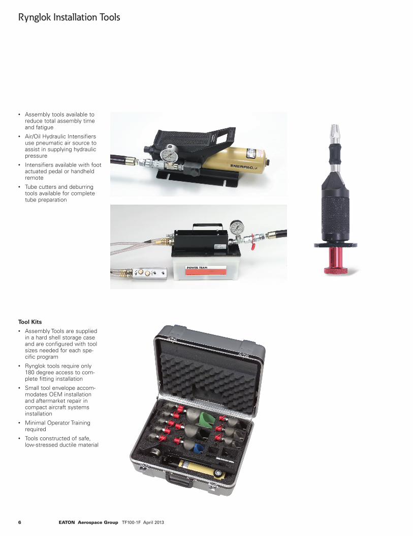
Rynglok Installation Tools
• Assembly tools available to reduce total assembly time and fatigue• Air/Oil Hydraulic Intensifiers use pneumatic air source to assist in supplying hydraulic pressure• Intensifiers available with foot actuated pedal or handheld remote• Tube cutters and deburring tools available for complete tube preparation
Tool Kits
• Assembly Tools are supplied in a hard shell storage case and are configured with tool sizes needed for each spe- cific program • Rynglok tools require only 180 degree access to com- plete fitting installation• Small tool envelope accom- modates OEM installation and aftermarket repair in compact aircraft systems installation• Minimal Operator Training required• Tools constructed of safe, low-stressed ductile material
EATON Aerospace Group TF100-1F April 2013 7
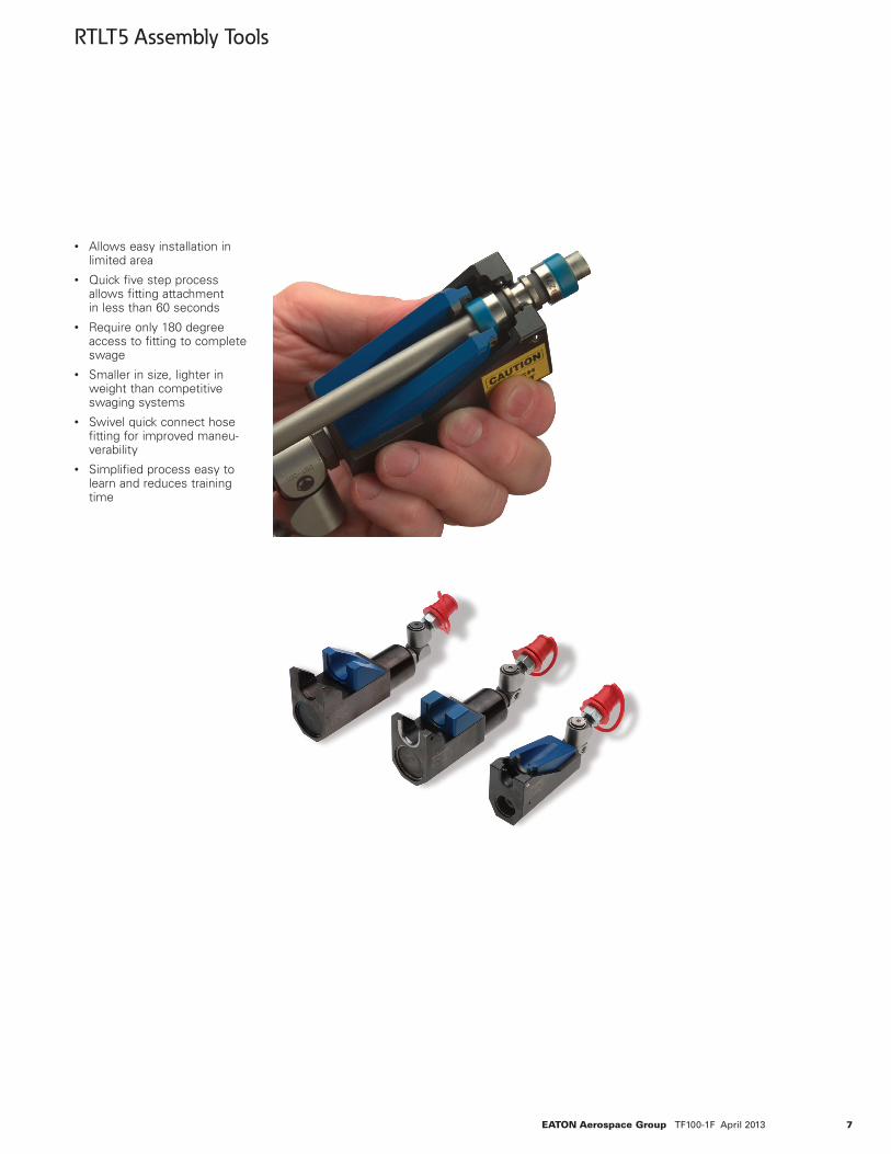
• Allows easy installation in limited area• Quick five step process allows fitting attachment in less than 60 seconds• Require only 180 degree access to fitting to complete swage• Smaller in size, lighter in weight than competitive swaging systems• Swivel quick connect hose fitting for improved maneu- verability• Simplified process easy to learn and reduces training time
RTLT5 Assembly Tools

8 EATON Aerospace Group TF100-1F April 2013
Rynglok Fitting System Installation SequenceSIMPLE AND EASY
1. Mark the Tube
Position the marking gauge on the end of the cut tube. Use a suitable marking pen to make the position and inspection marks. Electro etching of the position and inspection marks is an acceptable method of marking and is common for production tubing.
2. Position the Fitting
Place the fitting on the tube within the limits of the positioning mark.
3. Position the Tool
When using the tool in the forward mode as shown, position the tool onto the fitting with the tube side of the ring nested into the moveable jaw. If positioned properly, the front end of the tool will be in the fitting groove. Make sure that the fitting is bottomed into the tool.
Fitting Groove
Inspection Mark
Moveable Jaw
Position Mark

EATON Aerospace Group TF100-1F April 2013 9
4. Swaging the Fitting
To swage the fitting, apply pressure. Upon completion of swaging, release the pressure, the moveable jaw will return to the original position.
5. Inspect the Installation
Visually inspect the ring to assure it is fully advanced onto the fitting using the inspection gauge. Be sure to verify that the edge of the fit-ting is within the limits of the inspection mark.
The above steps are repeated for each operation of the Rynglok fitting installation sequence.
For a more detailed outline of the Rynglok installation sequence see our installation bulletin.
Inspection Mark
Position Mark

10 EATON Aerospace Group TF100-1F April 2013
Basic Part Number Designation
R5 X 0 T
T = Titanium fitting material (6Al-4V) D = Aluminum fitting material (6061T6)
Configuration number (see tube fitting configuration sheet)
0 = Standard production fitting
Connection Type: 0 = Permanent, all Rynglok fitting ends 1 = ArcSeal® (separable) male or female 2 = Flareless (separable) male or female 3 = Flared (separable) male or female
R5 = Rynglok titanium high pressure fitting RA = Rynglok aluminum low pressure fitting L5 = Lightweight Rynglok titanium high pressure fitting, optimized for size and weight in -04, -06, -08 sizes only.
Example: R51003T10
Rynglok fitting, female ArcSeal® (separable) to Rynglok fitting in the 90° elbow configuration.
How to Order
R5XXXXT ( ) ( ) ( )
Port No. 3 (side port)1,2
Port No. 2 (right port)1,2
Port No. 1 (left port)1, largest Rynglok fitting end on the run, if all ends are Rynglok or any separable end
Basic part number
Example: RA0054D100608
Rynglok fitting, reducing tee, all legs permanent.
Example: L51054T080406
Lightweight Rynglok reducing tee, with female ArcSeal® separable.
Rynglok Fitting Part Number System and How to Order
1 Tube size is specified in 1/16" increments, (i.e., 08=8/16ths or 1/2")2 Port 2 and 3 only required for reducer fittings
NOTE: Port numbering system is in accordance with AIR 1590.
For additional information contact Eaton, Aerospace Group, Fluid & Electrical Distribution Division, 300 S. East Ave., Jackson, Michigan 49203 Ph: (517) 787-8121 Fax: (517) 789-2947.
Port No. 1 5/8" tube size
Port No. 3 1/2" tube size
Port No.2 3/8" tube size
Port No. 1 1/2" tube size
Port No. 3 3/8" tube size
Port No. 2 1/4" tube size
XX

EATON Aerospace Group TF100-1F April 2013 11
High Pressure Rynglok Tube Fitting Configuration
Permanent to “AN” Flared Permanent to “MS” Flareless Permanent Male Male Female Male Male Female to Permanent AS4395 AS4396 NAS 1760 (MS33656) (MS33657) AS1708 MS33514 MS33515 Modified
Union
Non-Reducer RA0001D( ) RA3021D( ) RA3041D( ) RA3001D( ) RA2021D( ) RA2041D( ) RA2001D( ) Reducer RA0051D( )( ) RA3071D( )( ) RA3091D( )( ) RA3051D( )( ) RA2071D( )( ) RA2091D( )( ) RA2051D( )( )
45° Elbow Non-Reducer RA0002D( ) RA3022D( ) RA3042D( ) RA3002D( ) RA2022D( ) RA2042D( ) RA2002D( ) Reducer RA0052D( )( ) RA3072D( )( ) RA3092D( )( ) RA3052D( )( ) RA2072D( )( ) RA2092D( )( ) RA2052D( )( )
90° Elbow
Non-Reducer RA0003D( ) RA3023D( ) RA3043D( ) RA3003D( ) RA2023D( ) RA2043D( ) RA2003D( ) Reducer RA0053D( )( ) RA3073D( )( ) RA3093D( )( ) RA3053D( )( ) RA2073D( )( ) RA2093D( )( ) RA2053D( )( )
Tee (Separable on Run)
Non-Reducer RA0004D( ) RA3024D( ) RA3044D( ) RA3004D( ) RA2024D( ) RA2044D( ) RA2004D( ) Reducer RA0054D( )( )( ) RA3074D( )( )( ) RA3094D( )( )( ) RA3054D( )( )( ) RA2074D( )( )( ) RA2094D( )( )( ) RA2054D( )( )( )
Tee (Separable on Side)
Non-Reducer RA3026D( ) RA3046D( ) RA3006D( ) RA2026D( ) RA2046D( ) RA2006D( ) Reducer RA3076D( )( )( ) RA3096D( )( )( ) RA3056D( )( )( ) RA2076D( )( )( ) RA2096D( )( )( ) RA2056D( )( )( )
Low Pressure Rynglok Tube Fitting Configuration
Permanent to Arcseal® Permanent to “MS” Flareless Permanent Male Male Female Male Male Female to MIL-F-85421/2 or Mates with Permanent MIL-F-85421/1 or MIL-F-85720/1 MIL-F-85421 & NAS 1760 MIL-F-85720/1 Bulkhead MIL-F-85720 MS33514 MS33515 Modified
Union
Non-Reducer R50001T( ) R51021T( ) R51041T( ) R51001T( ) R52021T( ) R52041T( ) R52001T( ) Reducer R50051T( )( ) R51071T( )( ) R51091T( )( ) R51051T( )( ) R52071T( )( ) R52091T( )( ) R52051T( )( )
45° Elbow Non-Reducer R50002T( ) R51022T( ) R51042T( ) R51002T( ) R52022T( ) R52042T( ) R52002T( ) Reducer R50052T( )( ) R51072T( )( ) R51092T( )( ) R51052T( )( ) R52072T( )( ) R52092T( )( ) R52052T( )( )
90° Elbow
Non-Reducer R50003T( ) R51023T( ) R51043T( ) R51003T( ) R52023T( ) R52043T( ) R52003T( ) Reducer R50053T( )( ) R51073T( )( ) R51093T( )( ) R51053T( )( ) R52073T( )( ) R52093T( )( ) R52053T( )( )
Tee (Separable on Run)
Non-Reducer R50004T( ) R51024T( ) R51044T( ) R51004T( ) R52024T( ) R52044T( ) R52004T( ) Reducer R50054T( )( )( ) R51074T( )( )( ) R51094T( )( )( ) R51054T( )( )( ) R52074T( )( )( ) R52094T( )( )( ) R52054T( )( )( )
Tee (Separable on Side)
Non-Reducer R51026T( ) R51046T( ) R51006T( ) R52026T( ) R52046T( ) R52006T( ) Reducer R51076T( )( )( ) R51096T( )( )( ) R51056T( )( )( ) R52076T( )( )( ) R52096T( )( )( ) R52056T( )( )( )For sizes -04, -06, or -08 the R5 prefix will be replaced by L5 in the Part Number.

Copyright © 2013 EatonAll Rights ReservedForm No. TF100-1FApril 2013
Eaton Aerospace Group Fluid & Electrical Distribution Division 300 South East Avenue Jackson, Michigan 49203-1972 Phone: (517) 787 8121 Fax: (517) 789 2947
EatonAerospace Group9650 Jeronimo RoadIrvine, California 92618Phone: (949) 452 9500Fax: (949) 452 9555www.eaton.com/aerospace