Rupture of thin films formed during droplet...
17
Proc. R. Soc. A (2010) 466, 1229–1245 doi:10.1098/rspa.2009.0425 Published online 11 December 2009 Rupture of thin films formed during droplet impact BY RAJEEV DHIMAN* AND SANJEEV CHANDRA Centre for Advanced Coating Technologies, Department of Mechanical and Industrial Engineering, University of Toronto, 5 King’s College Road, Toronto, Ontario M5S 3G8, Canada Rupture of liquid films formed during droplet impact on a dry solid surface was studied experimentally. Water droplets (580 ± 70 μm) were photographed as they hit a solid substrate at high velocities (10–30 m s −1 ). Droplet–substrate wettability was varied over a wide range, from hydrophilic to superhydrophobic, by changing the material of the substrate (glass, Plexiglas, wax and alkylketene dimer). Both smooth and rough wax surfaces were tested. Photographs of impact showed that as the impact velocity increased and the film thickness decreased, films became unstable and ruptured internally through the formation of holes. However, the impact velocity at which rupture occurred was found to first decrease and then increase with the liquid–solid contact angle, with wax showing rupture at all impact velocities tested. A thermodynamic stability analysis combined with a droplet spreading model predicted the rupture behaviour by showing that films would be stable at very small or at very large contact angles, but unstable in between. Film rupture was found to be greatly promoted by surface roughness. Keywords: droplet impact; film rupture; wettability; superhydrophobic surfaces 1. Introduction When a liquid droplet impacts on a dry solid surface, it spreads radially outwards until its kinetic energy has been dissipated, creating a thin liquid film whose radius and thickness depend primarily upon initial droplet diameter, impact velocity and liquid properties (Pasandideh-Fard et al. 1996; detailed reviews on the general phenomena of droplet impact on solid and liquid layers have been given by Lesser & Field 1983; Rein 1993; Yarin 2006). Many engineering applications that use spray deposition require the deposited liquid layer to remain stable and adhere to the substrate. For example, in spray painting or coating, a thin, uniform liquid film is applied on a substrate and it must stay intact until it dries. During pesticide spraying on plants, the liquid should remain on the leaf surface and not drip to the soil where it can contaminate underground water. A contiguous liquid layer is often difficult to achieve because droplets impinging with sufficient velocity to spread them into a thin film may disintegrate into smaller fragments that bounce off. *Author for correspondence ([email protected]). Received 12 August 2009 Accepted 11 November 2009 This journal is © 2009 The Royal Society 1229 on April 22, 2018 http://rspa.royalsocietypublishing.org/ Downloaded from
Transcript of Rupture of thin films formed during droplet...
on April 22, 2018http://rspa.royalsocietypublishing.org/Downloaded from
Proc. R. Soc. A (2010) 466, 1229–1245doi:10.1098/rspa.2009.0425
Published online 11 December 2009
Rupture of thin films formed duringdroplet impact
BY RAJEEV DHIMAN* AND SANJEEV CHANDRA
Centre for Advanced Coating Technologies, Department of Mechanicaland Industrial Engineering, University of Toronto, 5 King’s College Road,
Toronto, Ontario M5S 3G8, Canada
Rupture of liquid films formed during droplet impact on a dry solid surface was studiedexperimentally. Water droplets (580 ± 70 μm) were photographed as they hit a solidsubstrate at high velocities (10–30 m s−1). Droplet–substrate wettability was varied overa wide range, from hydrophilic to superhydrophobic, by changing the material of thesubstrate (glass, Plexiglas, wax and alkylketene dimer). Both smooth and rough waxsurfaces were tested. Photographs of impact showed that as the impact velocity increasedand the film thickness decreased, films became unstable and ruptured internally throughthe formation of holes. However, the impact velocity at which rupture occurred was foundto first decrease and then increase with the liquid–solid contact angle, with wax showingrupture at all impact velocities tested. A thermodynamic stability analysis combinedwith a droplet spreading model predicted the rupture behaviour by showing that filmswould be stable at very small or at very large contact angles, but unstable in between.Film rupture was found to be greatly promoted by surface roughness.
Keywords: droplet impact; film rupture; wettability; superhydrophobic surfaces
1. Introduction
When a liquid droplet impacts on a dry solid surface, it spreads radially outwardsuntil its kinetic energy has been dissipated, creating a thin liquid film whose radiusand thickness depend primarily upon initial droplet diameter, impact velocity andliquid properties (Pasandideh-Fard et al. 1996; detailed reviews on the generalphenomena of droplet impact on solid and liquid layers have been given byLesser & Field 1983; Rein 1993; Yarin 2006). Many engineering applications thatuse spray deposition require the deposited liquid layer to remain stable and adhereto the substrate. For example, in spray painting or coating, a thin, uniform liquidfilm is applied on a substrate and it must stay intact until it dries. During pesticidespraying on plants, the liquid should remain on the leaf surface and not drip tothe soil where it can contaminate underground water. A contiguous liquid layeris often difficult to achieve because droplets impinging with sufficient velocityto spread them into a thin film may disintegrate into smaller fragments thatbounce off.*Author for correspondence ([email protected]).
Received 12 August 2009Accepted 11 November 2009 This journal is © 2009 The Royal Society1229

1230 R. Dhiman and S. Chandra
on April 22, 2018http://rspa.royalsocietypublishing.org/Downloaded from
Owing to the practical importance of the subject, many studies (e.g. Stow &Hadfield 1981; Mehdizadeh et al. 2004b; Xu et al. 2005; Deegan et al. 2008) havebeen conducted to investigate the cause of droplet break-up during impact. Thefocus of these studies has been the instability along the edges of the thin filmcreated by the impacting droplet (Allen 1975; Kim et al. 2000; Mehdizadeh et al.2004b) and the effect of factors such as surface roughness (Stow & Hadfield 1981),surrounding gas pressure (Xu et al. 2005, 2007), substrate elasticity (Pepper et al.2008) and solidification (Dhiman & Chandra 2005) on droplet splashing. Most ofthese studies have been conducted at relatively low impact velocities (1–10 m s−1),in which fluid instabilities around the edge of the spreading droplet caused theformation of long fingers that detached to form satellite droplets (Allen 1975; Kimet al. 2000). At higher impact velocities, up to 40 m s−1, photographs of waterdroplets impacting a polished stainless steel surface showed that the liquid filmbecame so thin that it ruptured internally and then, as the holes expanded owingto surface tension, disintegrated completely (Mehdizadeh et al. 2004b). Whenthe substrate was heated sufficiently to trigger nucleate boiling, so that vapourbubbles punctured the liquid film at a large number of points, it disintegratedinto a cloud of fine droplets (Mehdizadeh & Chandra 2006). Most practical sprayapplications use high impact velocities, and it is likely that a major cause ofdroplet break-up is internal rupture rather than edge instabilities.
The formation of holes in a stationary liquid film has been the subject of manystudies (Padday 1970; Taylor & Michael 1973; Sharma & Ruckenstein 1989).Padday (1970) measured the critical thickness below which water films rupturedon a variety of surfaces and found that the critical thickness increased with theliquid–solid contact angle. Taylor & Michael (1973) investigated the formation ofa hole in water and mercury films by blowing an air jet onto the film. They appliedthe Young–Laplace equation of capillarity to the hole profile and found that fora given film thickness and contact angle, there exists a critical hole size: largerholes grow, whereas smaller ones heal. Sharma & Ruckenstein (1989) presenteda thermodynamic analysis which considered the difference in free energy of anintact liquid film and one with a hole in it. Their predictions of a critical filmthickness, below which films became unstable when punctured by a hole of agiven diameter, matched well with the observations of Padday (1970). Kheshgi &Scriven (1991) investigated the mechanisms responsible for hole formation andargued that the nucleation of a hole is preceded by a film thinning disturbancethat locally thins the film. Redon et al. (1991) studied the rate of hole growth andfound that their velocity is independent of film thickness, but critically dependenton the receding contact angle formed by film liquid on the surface.
In a previous paper (Dhiman & Chandra 2008), we investigated the internalrupture of radially spreading films formed by the normal impact of a waterjet on a horizontal plate. Combining a simple mathematical model with thethermodynamic analysis of Sharma & Ruckenstein (1989) to predict filmthickness, we developed a criterion to predict film rupture by calculating a criticalReynolds number (Re) for the impacting jet, above which rupture would occur.The critical Re depended on both the initial diameter of the hole initiated in thefilm and the liquid–solid contact angle.
Our objective in this study was to determine conditions under which animpacting droplet, flattening into a thin film, would rupture internally. We variedsubstrate wettability by using four different surface materials (Plexiglas, glass,
Proc. R. Soc. A (2010)

Rupture of droplet impact films 1231
on April 22, 2018http://rspa.royalsocietypublishing.org/Downloaded from
wax and alkylketene dimer (AKD)) for which advancing liquid–solid contact anglevaried from 58◦ to 164◦. Wax substrates with two different values of surfaceroughness were tested: 0.13 and 1.98 μm. Impact velocity was varied from 10 to30 m s−1, giving Reynolds and Weber (We) number ranges of 5800–17 400 and800–7200, respectively. We developed a simple criterion, based on the analysis ofSharma & Ruckenstein (1989), to predict conditions under which the liquid filmwould rupture.
2. Experimental method
To produce a liquid film thin enough to rupture while spreading, small dropletswith high impact velocities are required. This was achieved by using a dropletgenerator that produced sub-millimeter size droplets, which collided with asubstrate mounted on the rim of a 0.4 m diameter, rotating flywheel. Bysynchronizing the position of the rotating substrate with the ejection of droplet,the substrate hit the falling droplet at a high velocity while a fast-shutter charge-coupled device (CCD) camera captured the dynamics of impact. Figure 1 showsa schematic of the experimental apparatus, which has been described in detail byMehdizadeh et al. (2004a).
Droplets of distilled water, 580 ± 70 μm in diameter, were produced using apneumatic drop-on-demand droplet generator (Cheng & Chandra 2003), whichworks by applying a gas pressure pulse on the free surface of water contained ina cavity, forcing a single droplet out of a small hole (250 μm) in its bottom. Theejected droplet fell vertically downwards with a velocity less than 1 m s−1 towardsthe centre of the substrate. The test surface was glued to an aluminium coupon(38.1 × 25.4 × 1 mm thickness) that could be screwed onto an aluminium platebolted to the flywheel rim. The rotational speed of the flywheel was varied from470 to 1410 r.p.m., giving linear velocities of 10–30 m s−1, which were maintainedwithin ±1% by a digital motion controller. The position of the revolving substratewas detected by an optical sensor. The signal was then sent to a time delayunit (DG535; Stanford Research Systems, CA, USA), which produced threesignals in reference to the input signal. These signals were sent to a CCDcamera, an electronic flash unit and the droplet generator, so that as the fallingdroplet was hit by the rotating substrate, the camera and flash were triggeredto capture a single image of an impacting droplet. The CCD camera (Sensicam,Optikon Corporation, Kitchner, Ontario, Canada) used to capture the images ofdroplet deformation during impact could be shuttered as fast as 0.1 μs with highresolution (1280 × 1024 pixels). Illumination during impact was provided by anelectronic flash of 10 μs duration.
By varying the delay between droplet generation and triggering the flash,different stages of droplet deformation were captured and impact dynamicsreconstructed from a sequence of these photographs. This technique, commonlyknown as single shot photography, yielded higher-resolution images than possiblewith typical high-speed video cameras and allowed us to clearly observe tinyholes that formed in films. However, the repeatability of droplet impact was lessthan the time interval between images, and therefore there are no times indicatednext to individual frames. There were two reasons for this drop-to-drop variation:the instant of droplet impact varied slightly owing to air turbulence caused by
Proc. R. Soc. A (2010)

1232 R. Dhiman and S. Chandra
on April 22, 2018http://rspa.royalsocietypublishing.org/Downloaded from
digital motioncontroller
droplet generator
droplet
test surface
flash unit
optical sensor
counterweight
flywheel
motor
high-frequencypulse in
camera
frequencydivider
5 Vswitch
low-frequencypulse out
AND gate
time delay unit
Figure 1. Schematic of the experimental apparatus.
substrate rotation; and droplet recoil, which is driven by capillary forces, wasaffected by local variations in surface wettability and roughness that randomlyalter droplet shape during receding. This lack of timing information, however, wasnot a serious limitation as we did not make any time-dependent measurementsfrom the images.
Four different substrate materials were used in this study: glass, Plexiglas,wax and AKD, which is a superhydrophobic surface (Mohammadi et al. 2004).Two wax surfaces, with differing roughness, were prepared. Molten wax waspoured onto a mirror-polished aluminium plate; the upper surface of the wax,which solidified in contact with air, was much rougher than the lower surface.All surfaces were characterized by measuring their roughness and contact angles(advancing, receding and equilibrium) formed with water droplets. Roughnesswas measured with an interferometric microscope that scanned each surfaceand produced a three-dimensional profile of it. Each surface was scanned atfive different locations, and the results were averaged to obtain an averagefor the entire surface. Average surface roughness Ra was 0.01 μm for the glass
Proc. R. Soc. A (2010)

Rupture of droplet impact films 1233
on April 22, 2018http://rspa.royalsocietypublishing.org/Downloaded from
Table 1. Characteristics of the solid surfaces used.
equilibrium contact advancing contact receding contact average roughnesssurface angle θ (◦) angle θa (◦) angle θr (◦) Ra (μm)
glass 47 58 20 0.01 ± 0.003Plexiglas 71 80 40 0.02 ± 0.006smooth wax 105 107 84 0.13 ± 0.02rough wax 102 106 85 1.98 ± 0.62AKD 160 164a 147a 1.25 ± 0.17a
aMohammadi et al. (2004).
substrate, 0.02 μm for Plexiglas, 0.13 μm for smooth wax and 1.98 μm forrough wax. Average roughness of the AKD samples was 1.25 μm (Mohammadiet al. 2004). In all cases, surface roughness was an order of magnitude lessthan the thickness of the liquid film, which was typically approximately20 μm.
The procedure followed to measure the advancing and receding contact angleswas that described by Johnson & Dettre (1993). A micrometre-controlled syringewas used to dispense small water droplets on a surface through a needle. Withthe needle still inside the sessile droplet formed, water was added slowly withthe syringe until the liquid–solid contact line at the edge of the droplet beganto advance. The motion of the droplet was recorded with a CCD camera.Images of the moving contact line were imported into image analysis software(IMAGEJ; National Institutes of Health, USA), and the advancing contact anglewas measured. Receding contact angles were measured by reversing the flow of theliquid, sucking water back into the syringe until the contact line began to recede.The results obtained for the contact angles for all surfaces used along with theroughness measurements are shown in table 1. All experiments were performedat 25◦C, controlled by a thermostat-monitored room air conditioning system, and1 atm pressure.
3. Results and discussion
Figure 2 shows three different sequences of the impact of water droplets on asmooth glass surface at three different impact velocities: 10, 20 and 30 m s−1.Glass had the lowest contact angle of the four surfaces tested, θ = 47◦. Eachvertical column shows successive stages of impact at one of the velocities, whichyielded Reynolds numbers (Re) of 5800, 11 600 and 17 400, respectively. Dropletsflattened into a thin film after impact as they reached their maximum extension(figure 2b), which was followed by retraction until they eventually attainedequilibrium. The diameter Dmax of the films at maximum extension increasedwith Re (figure 2b), and hence their thickness decreased. At Re = 5800 and11 600 the films remained stable, but at Re = 17 400 the film ruptured and severalholes became visible (figure 2c), which continued to grow afterwards (figure 2d,e)rendering the film unstable.
Proc. R. Soc. A (2010)

1234 R. Dhiman and S. Chandra
on April 22, 2018http://rspa.royalsocietypublishing.org/Downloaded from
Re 5800 11 600 17 400
time
0 3 mm
We 800 3200 7200
(a)
(c)
(d)
(e)
(b)
Figure 2. Impact of 580 μm diameter water droplets with different Re on smooth glass surfaces.
Reducing the wettability of the substrate changed the impact dynamicssignificantly and promoted hole formation. Figure 3 shows the impact of waterdroplets on a Plexiglas surface that has a contact angle higher than that onglass (θ for Plexiglas = 71◦). The impact at Re = 5800 was similar to the oneseen on glass surfaces. However, droplets impacting at both Re = 11 600 and17 400 now became unstable and ruptured. At Re = 17 400, where Dmax wasthe greatest, the number of holes formed was also larger than that observedat Re = 11 600.
Proc. R. Soc. A (2010)

Rupture of droplet impact films 1235
on April 22, 2018http://rspa.royalsocietypublishing.org/Downloaded from
Re
time
0 3 mm
5800 11 600 17 400
We 800 3200 7200(a)
(b)
(c)
(d)
Figure 3. Impact of 580 μm diameter water droplets with different Re on smooth Plexiglas surfaces.
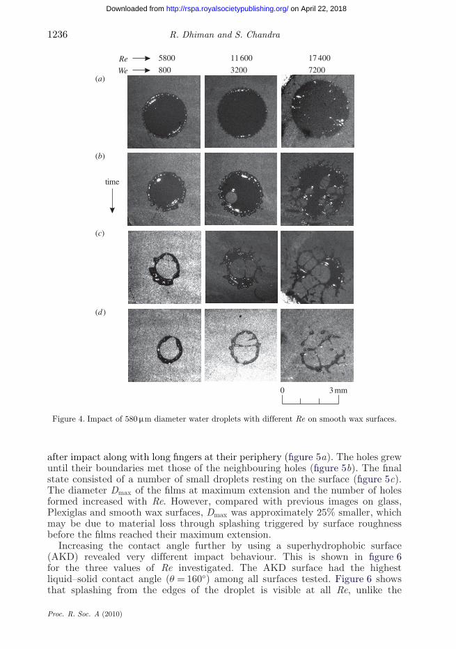
Impact on a smooth wax surface, whose contact angle is even larger than thaton Plexiglas (θ for wax = 105◦), showed rupture at all Re in our experiments,as shown in figure 4. In addition, holes on wax surfaces are much larger, unlikethose on glass and Plexiglas surfaces, because they grow rapidly owing to theirhigh contact angle with the solid. The rate at which holes grow has been shownto be critically dependent on the receding contact angle of the liquid with thesolid (Redon et al. 1991). As a result, the area covered by the liquid after theimpact of water drops on wax surfaces was the least compared with both glassand Plexiglas surfaces.
The dynamics of droplet impact on a wax surface with roughness Ra=1.98 μmwas quite different from that on smooth (Ra = 0.13 μm) wax and is shown infigure 5. A large number of holes appeared in the water film almost immediately
Proc. R. Soc. A (2010)
1236 R. Dhiman and S. Chandra
on April 22, 2018http://rspa.royalsocietypublishing.org/Downloaded from
Re
time
0 3 mm
5800 11 600 17 400
We 800 3200 7200(a)
(b)
(c)
(d )
Figure 4. Impact of 580 μm diameter water droplets with different Re on smooth wax surfaces.
after impact along with long fingers at their periphery (figure 5a). The holes grewuntil their boundaries met those of the neighbouring holes (figure 5b). The finalstate consisted of a number of small droplets resting on the surface (figure 5c).The diameter Dmax of the films at maximum extension and the number of holesformed increased with Re. However, compared with previous images on glass,Plexiglas and smooth wax surfaces, Dmax was approximately 25% smaller, whichmay be due to material loss through splashing triggered by surface roughnessbefore the films reached their maximum extension.
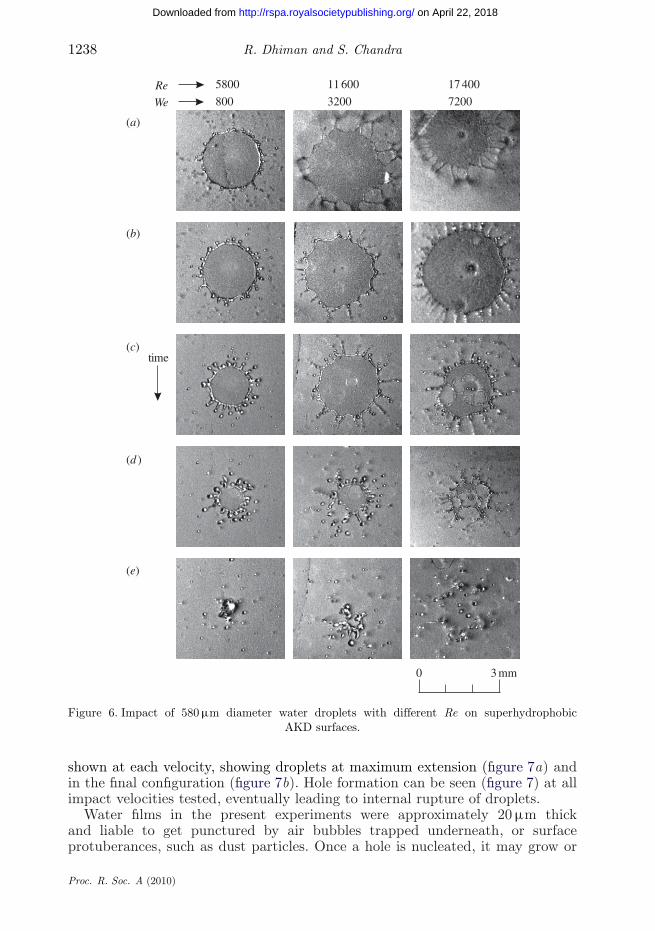
Increasing the contact angle further by using a superhydrophobic surface(AKD) revealed very different impact behaviour. This is shown in figure 6for the three values of Re investigated. The AKD surface had the highestliquid–solid contact angle (θ = 160◦) among all surfaces tested. Figure 6 showsthat splashing from the edges of the droplet is visible at all Re, unlike the
Proc. R. Soc. A (2010)

Rupture of droplet impact films 1237
on April 22, 2018http://rspa.royalsocietypublishing.org/Downloaded from
Re
time
0 3 mm
5800 11 600 17 400
We 800 3200 7200(a)
(b)
(c)
Figure 5. Impact of 580 μm diameter water droplets with different Re on rough wax surfaces.
other surfaces (figures 2–5), which mostly exhibited internal rupture. Longfingers formed around the edges of the drop, which then detached as satellitedroplets, especially as the droplet receded (figure 6c–e), leaving only an arrayof small droplets on the surface. Hole formation on the AKD sample, eventhough it was rough (Ra = 1.25 μm), was minimal at Re = 5800 and 11 600,but occurred at Re = 17 400. In contrast, the rough wax surface, which hadalmost the same roughness, showed extensive hole formation at all Re. Thisbehaviour suggests that hole formation is suppressed on superhydrophobicsurfaces. Films on AKD surfaces become unstable through continuous sheddingof satellite droplets from their edges during retraction (figure 6e), whereas on theother surfaces tested, fragmentation of liquid films commenced with growth ofinternal holes.
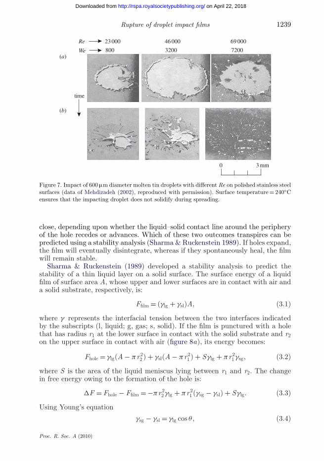
High liquid–solid contact angles are also encountered during the impact ofmolten metal droplets, which have high surface tension. Mehdizadeh (2002)photographed the impact of 600 μm diameter molten tin droplets on a mirror-polished stainless steel surface held at a temperature above that of the dropletmelting point, so that impact was isothermal and droplets did not solidify duringimpact. Aziz & Chandra (2000) measured dynamic liquid–solid contact anglesfor molten tin on stainless steel and found both advancing and receding contactangles to be near 140◦. Droplet impact velocity was varied between 10 and30 m s−1 giving Re values from 2.3 × 10⁴ to 6.9 × 10⁴. Figure 7 shows photographstaken by Mehdizadeh (2002) at three different impact velocities: two images are
Proc. R. Soc. A (2010)
1238 R. Dhiman and S. Chandra
on April 22, 2018http://rspa.royalsocietypublishing.org/Downloaded from
Re
0 3 mm
time
5800 11 600 17 400
We 800 3200 7200
(a)
(b)
(c)
(d )
(e)
Figure 6. Impact of 580 μm diameter water droplets with different Re on superhydrophobicAKD surfaces.
shown at each velocity, showing droplets at maximum extension (figure 7a) andin the final configuration (figure 7b). Hole formation can be seen (figure 7) at allimpact velocities tested, eventually leading to internal rupture of droplets.
Water films in the present experiments were approximately 20 μm thickand liable to get punctured by air bubbles trapped underneath, or surfaceprotuberances, such as dust particles. Once a hole is nucleated, it may grow or
Proc. R. Soc. A (2010)
Rupture of droplet impact films 1239
on April 22, 2018http://rspa.royalsocietypublishing.org/Downloaded from
23 000 69 00046 000Re
time
0 3 mm
We 800 3200 7200(a)
(b)
Figure 7. Impact of 600 μm diameter molten tin droplets with different Re on polished stainless steelsurfaces (data of Mehdizadeh (2002), reproduced with permission). Surface temperature = 240◦Censures that the impacting droplet does not solidify during spreading.
close, depending upon whether the liquid–solid contact line around the peripheryof the hole recedes or advances. Which of these two outcomes transpires can bepredicted using a stability analysis (Sharma & Ruckenstein 1989). If holes expand,the film will eventually disintegrate, whereas if they spontaneously heal, the filmwill remain stable.
Sharma & Ruckenstein (1989) developed a stability analysis to predict thestability of a thin liquid layer on a solid surface. The surface energy of a liquidfilm of surface area A, whose upper and lower surfaces are in contact with air anda solid substrate, respectively, is:
Ffilm = (γlg + γsl)A, (3.1)
where γ represents the interfacial tension between the two interfaces indicatedby the subscripts (l, liquid; g, gas; s, solid). If the film is punctured with a holethat has radius r1 at the lower surface in contact with the solid substrate and r2on the upper surface in contact with air (figure 8a), its energy becomes:
Fhole = γlg(A − πr22 ) + γsl(A − πr2
1 ) + Sγlg + πr21 γsg, (3.2)
where S is the area of the liquid meniscus lying between r1 and r2. The changein free energy owing to the formation of the hole is:
�F = Fhole − Ffilm = −πr22 γlg + πr2
1 (γsg − γsl) + Sγlg. (3.3)
Using Young’s equation
γsg − γsl = γlg cos θ , (3.4)
Proc. R. Soc. A (2010)

1240 R. Dhiman and S. Chandra
on April 22, 2018http://rspa.royalsocietypublishing.org/Downloaded from
h
r2
r1
(a)
q
(b)
q
(c)
S
q
Figure 8. Schematics of hole profile at different contact angles: (a) small θ , large S , film stable;(b) intermediate θ , small S , film unstable and (c) large θ , large S , film stable.
we have an expression for the free energy change:
�F = γlg(S − πr22 + πr2
1 cos θ). (3.5)
The stability of the film depends on the magnitude of �F : if �F < 0, the holereduces the energy of the film and will grow; if �F > 0, the hole will spontaneouslyclose and the film will remain intact. Therefore, for film stability, we requireS to be large enough to outweigh the negative term on the right-hand side ofequation (3.5). Sharma & Ruckenstein (1989) derived the following expression forthe surface area S of the liquid meniscus by solving the Young–Laplace equationof capillarity:
S = 12πr2
1
{(1 + cos2 θ) sinh
(2h/r1
sin θ
)+ 2 cos θ
[cosh
(2h/r1
sin θ
)− 1
]+ 2
hr1
sin θ
}.
(3.6)r2 was given as:
r2 = r1
[cosh
(h/r1
sin θ
)+ sinh
(h/r1
sin θ
)cos θ
]. (3.7)
�F is a function of h/r1 and θ . In general, though, S is large when θ approacheseither 0◦ or 180◦, as shown in figure 8a,c. Both high and low contact anglesproduce a meniscus with large surface area when a hole is created in the liquidfilm. The large surface energy associated with this exposed area will inhibitfurther expansion of the hole, making it close. In contrast, intermediate contactangles (θ ∼ 90◦) produce a meniscus with small surface area (figure 8b), renderingsuch a hole energetically favourable and making it grow.
Proc. R. Soc. A (2010)

Rupture of droplet impact films 1241
on April 22, 2018http://rspa.royalsocietypublishing.org/Downloaded from
The boundary between film stability and instability can be determined bysetting �F = 0 in equation (3.5), combined with equations (3.6) and (3.7), toobtain the critical film thickness, hc, below which the film would be unstablewhen a hole of radius r1 was created
2(
hc
r1
)1
sin θ= 1 + (1 − cos θ)2
sin2 θ
[cosh
(2hc
r1
1sin θ
)− sinh
(2hc
r1
1sin θ
)]. (3.8)
The ratio hc/r1 is an implicit function of the contact angle, θ .To apply this stability criterion to droplet impact, we need a way of estimating
film thickness h formed following impact. An estimate of h may be obtained byusing mass conservation of the droplet before and after impact when it resemblesa thin disc (figure 2b). The mass of the droplet when equated before and afterimpact (at maximum spread) yields:
ρπ
6D3
o = ρπ
4D2
maxh, (3.9)
where ρ is the density of the film liquid, Do is the diameter of droplet beforeimpact and Dmax is the diameter of the film at maximum spread of the droplet.Simplifying equation (3.9) gives:
h = 2Do
3ξ 2max
, (3.10)
where ξmax(= Dmax/Do) is the maximum spread factor of the impacting droplet.To calculate ξmax, an energy balance model developed by Pasandideh-Fard et al.(1996) is used. According to this model, ξmax is given as:
ξmax = Dmax
Do=
√We + 12
3(1 − cos θa) + 4(We/√
Re), (3.11)
where θa is the advancing contact angle formed by droplet liquid with the solidsurface. Pasandideh-Fard et al. (1996) further showed that equation (3.11) maybe simplified as:
ξmax = 0.5 Re0.25, (3.12)
if We � √Re. This condition is satisfied in the present experiments (table 2). The
predictions for ξmax from equation (3.12) were compared with the correspondingvalues measured from the photographs. Once ξmax has been calculated, h can beestimated from equation (3.10). An alternative method of calculating an averagevalue of h directly from experiments was to measure Dmax from photographs andsetting:
hexp = 2Do
3ξ 2max,exp
, (3.13)
where ξmax,exp = Dmax,exp/Do.Table 2 compares predicted (from equations (3.10) and (3.12)) and measured
(equation (3.13)) values of spread factors and film thicknesses and shows thatthey predict film thickness quite well. Film thickness decreases as impact Re isincreased.
Proc. R. Soc. A (2010)

1242 R. Dhiman and S. Chandra
on April 22, 2018http://rspa.royalsocietypublishing.org/Downloaded from
Table 2. Comparison of measured spread factors and film thicknesses with predictions.
maximum spread factor ξmax film thickness h (μm)
Re We model experiment model experiment
5800 800 4.4 3.9 21 2711 600 3200 5.2 4.9 15 1717 400 7200 5.8 5.6 12 13
The calculated film thickness may be used in the criteria for film stability(equation (3.8)), written in the dimensionless form as:
2(
h∗c
r∗1
)1
sin θr= 1 + (1 − cos θr)2
sin2 θr
[cosh
(2h∗
c
r∗1
1sin θr
)− sinh
(2h∗
c
r∗1
1sin θr
)],
(3.14)where h∗
c = hc/Do and r∗1 = r1/Do. Note that the receding contact angle θr is used
in the above equation because holes in thin films have been shown to expand at arate which is critically dependent on θr (Redon et al. 1991). Using equation (3.10),we can write:
h∗ = 23ξ 2
max, (3.15)
where h∗ = h/Do. Substituting ξmax from equation (3.12) into equation (3.15)gives:
h∗ = 8
3√
Re. (3.16)
Setting h∗ = h∗c and substituting equation (3.16) into equation (3.14), the criterion
for film rupture during droplet impact is:(16
3r∗1 sin θr
)1√Rec
= 1 + (1 − cos θr)2
sin2 θr
[cosh
(16
3r∗1 sin θr
1√Rec
)
− sinh(
163r∗
1 sin θr
1√Rec
)], (3.17)
where Rec is the critical Reynolds number of impact at which the film rupturesthrough formation of holes. If Re > Rec, film rupture is likely to occur. Rec is afunction of two variables: receding contact angle, θr, and hole radius, r∗
1 . For agiven liquid, receding contact angle depends on the substrate: measured valuesare listed in table 1. The initial hole radius is more difficult to determine sinceonly rough, order-of-magnitude estimates can be made from photographs. Holesappear to be triggered by air bubbles trapped at the liquid–solid interface andincreasing surface roughness resulted in larger holes, possibly because of more airentrapment in surface crevices.
Figure 9 shows the variation of Rec with θr, for three different values of r∗1 .
Films are always stable for very large or very small contact angle, which resultsin a very large hole surface (figure 8), and are most likely to rupture at θr = 118◦,
Proc. R. Soc. A (2010)

Rupture of droplet impact films 1243
on April 22, 2018http://rspa.royalsocietypublishing.org/Downloaded from
0 20 40 60 80 100 120 140 160 180
108
107
106
105
104
103
102
qr
Recunstable
stable
Figure 9. Critical Reynolds number Rec of impact, above which films would rupture, as a functionof θr for different values of dimensionless hole radius, r∗
1 . Experimental data: square, glass; circle,Plexiglas; inverted triangle, smooth wax and rough wax; diamond, AKD; triangle, molten tin. Boldline, r∗
1 = 0.05; dashed line, r∗1 = 0.1; dotted line, r∗
1 = 0.15.
which corresponds to the minimum on each r∗1 curve. Experimental data for the
four surfaces used in our study, glass, Plexiglas, wax and AKD, are marked onthe figure. Since θr for smooth and rough wax surfaces was approximately thesame, their data points overlap. In addition, the experimental data of Mehdizadeh(2002) obtained from the impact of molten tin droplets on stainless steel surfacesare also shown. Solid symbols in figure 9 represent cases in which liquid filmsruptured, whereas hollow symbols show stable films.
Droplets on glass (θr = 20◦) and Plexiglas (θr = 40◦) surfaces did not becomeunstable until Re = 1.74 × 10⁴ and 1.16 × 10⁴, respectively (figures 2 and 3),whereas those on smooth wax (θr = 84◦) and rough wax (θr = 85◦) were unstableat all Re investigated (figures 4 and 5). This behaviour is best described byusing the line for r∗
1 = 0.1 to separate stable (below the line) and unstable(above the line) regions. Assuming r∗
1 = 0.15 suggests that droplets with even thelowest impact velocity would rupture on the Plexiglas surface, which we did notobserve. This would imply that holes with a diameter of 116 μm (corresponding tor∗1 = 0.1), but not as large as 174 μm (corresponding to r∗
1 = 0.15), formed duringimpact. Experimental observations of the earliest stages when holes were visibleappeared to confirm this observation: holes that were visible were approximately100 μm in diameter. The model is also able to predict hole formation seen in thephotographs taken by Mehdizadeh (2002) of molten tin droplets impacting on
Proc. R. Soc. A (2010)
1244 R. Dhiman and S. Chandra
on April 22, 2018http://rspa.royalsocietypublishing.org/Downloaded from
stainless steel surfaces (θr = 140◦). The holes seen in the films (figure 7) wereapproximately 200 μm in diameter, corresponding to r∗
1 = 0.15, and thereforeRe � Rec in all cases.
Film rupture becomes less likely once θr > 118◦, according to the model. Weobserved that there was much less film rupture (figure 6) on the superhydrophobicAKD surface (θr = 147◦) than on the rough wax (θr = 85◦), even though bothhad surface roughness of the same order of magnitude. The line r∗
1 = 0.05 betterpredicts the behaviour of AKD surfaces in figure 9. However, the model cannotmake predictions that are quantitatively more accurate since it is very sensitiveto the value of contact angle and initial hole diameter. It does predict the trendthat film rupture is suppressed on very hydrophobic surfaces.
4. Conclusions
We investigated the rupture of thin liquid films formed during the impact of580 μm water droplets onto a solid substrate for a range of impact velocities (10–30 m s−1). Four different substrates, of glass, Plexiglas, wax and superhydrophobicAKD, with equilibrium liquid–solid contact angles of 47◦, 71◦, 105◦ and 164◦,respectively, were used. Two different wax surfaces were prepared with differentroughnesses. Photographs of droplet impact showed that films ruptured throughthe formation of holes as they became thinner owing to an increase in impactvelocity. The impact velocity at which rupture occurred was found to dependon the liquid–solid contact angle: films with low (glass) or high (AKD) contactangles ruptured only at the highest impact velocity tested (30 m s−1), whereasfilms with intermediate contact angles (wax) ruptured at all impact velocities.A thermodynamic stability analysis combined with a droplet impact model wasused to explain film break-up behaviour by showing that films remain stable atvery small or very large contact angles, but are unstable in between. Film rupturewas greatly promoted by increasing surface roughness.
The authors gratefully acknowledge the support of the Natural Sciences and Engineering ResearchCouncil of Canada, which provided funding for this project and the assistance of Prof. AlidadAmirfazli of University of Alberta who supplied the superhydrophobic AKD surfaces used inexperiments.
References
Allen, R. F. 1975 The role of surface tension in splashing. J. Colloid Interf. Sci. 51, 350–351.(doi:10.1016/0021-9797(75)90126-5)
Aziz, S. D. & Chandra, S. 2000 Impact, recoil and splashing of molten metal droplets. Int. J. HeatMass Transf. 43, 2841–2857. (doi:10.1016/S0017-9310(99)00350-6)
Cheng, S. & Chandra, S. 2003 A pneumatic droplet-on-demand generator. Exp. Fluids 34, 755–762.(doi:10.1007/s00348-003-0629-6)
Deegan, R. D., Brunet, P. & Eggers, J. 2008 Complexities of splashing. Nonlinearity, 21, C1–C11.(doi:10.1088/0951-7715/21/1/C01)
Dhiman, R. & Chandra, S. 2005 Freezing-induced splashing during impact of molten metaldroplets with high Weber numbers. Int. J. Heat Mass Transf. 48, 5625–5638. (doi:10.1016/j.ijheatmasstransfer.2005.05.044)
Proc. R. Soc. A (2010)

Rupture of droplet impact films 1245
on April 22, 2018http://rspa.royalsocietypublishing.org/Downloaded from
Dhiman, R. & Chandra, S. 2008 Rupture of radially-spreading liquid films. Phys. Fluids 20, 092104.(doi:10.1063/1.2978186)
Johnson, R. E. & Dettre, R. H. 1993 In Wettability (ed. J. C. Berg), pp. 10–13. New York, NY:M. Dekker.
Kheshgi, H. S. & Scriven, L. E. 1991 Dewetting: nucleation and growth of dry regions. Chem. Eng.Sci. 46, 519–526. (doi:10.1016/0009-2509(91)80012-N)
Kim, H. Y., Feng, Z. C. & Chun, J. H. 2000 Instability of a liquid jet emerging from a dropletupon collision with a solid surface. Phys. Fluids 12, 531–541. (doi:10.1063/1.870259)
Lesser, M. B. & Field, J. E. 1983 The impact of compressible liquids. Annu. Rev. Fluid Mech. 15,97–122. (doi:10.1146/annurev.fl.15.010183.000525)
Mehdizadeh, N. Z. 2002 Droplet impact dynamics: effect of varying substrate temperature,roughness and droplet velocity. PhD thesis, University of Toronto, Toronto, Ontario, Canada.
Mehdizadeh, N. Z. & Chandra, S. 2006 Boiling during high velocity impact of water droplets on ahot stainless steel surface. Proc. R. Soc. A 462, 3115–3131. (doi:10.1098/rspa.2006.1722)
Mehdizadeh, N. Z., Raessi, M., Chandra, S. & Mostaghimi, J. 2004a Effect of substrate temperatureon splashing of molten tin droplets. J. Heat Transf. 126, 445–452. (doi:10.1115/1.1737778)
Mehdizadeh, N. Z., Chandra, S. & Mostaghimi, J. 2004b Formation of fingers around theedges of a drop hitting a metal plate with high velocity. J. Fluid Mech. 510, 353–373.(doi:10.1017/S0022112004009310)
Mohammadi, R., Wassink, J. & Amirfazli, A. 2004 Effect of surfactants on wetting of super-hydrophobic surfaces. Langmuir 20, 9657–9662. (doi:10.1021/la049268k)
Padday, J. F. 1970 Cohesive properties of thin films of liquids adhering to a solid surface. Spec.Discuss. Faraday Soc. 1, 64–74. (doi:10.1039/sd9700100064)
Pasandideh-Fard, M., Qaio, Y. M., Chandra, S. & Mostaghimi, J. 1996 Capillary effects duringdroplet impact on a solid surface. Phys. Fluids 8, 650–659. (doi:10.1063/1.868850)
Pepper, R. E., Courbin, L. & Stone, H. A. 2008 Splashing on elastic membranes: the importanceof early-time dynamics. Phys. Fluids 20, 082103. (doi:10.1063/1.2969755)
Redon, C., Brochard-Wyart, F. & Rondelez, F. 1991 Dynamics of dewetting. Phys. Rev. Lett. 66,715–718. (doi:10.1103/PhysRevLett.66.715)
Rein, M. 1993 Phenomena of liquid drop impact on solid and liquid surfaces. Fluid Dyn. Res. 12,61–93. (doi:10.1016/0169-5983(93)90106-K)
Sharma, A. & Ruckenstein, E. 1989 Dewetting of solids by the formation of holes in macroscopicliquid films. J. Colloid Interf. Sci. 133, 358–368. (doi:10.1016/S0021-9797(89)80044-X)
Stow, C. D. & Hadfield, M. G. 1981 An experimental investigation of fluid flow resulting from theimpact of a water drop with an unyielding dry surface. Proc. R. Soc. Lond. A 373, 419–441.(doi:10.1098/rspa.1981.0002)
Taylor, G. I. & Michael, D. H. 1973 On making holes in a sheet of fluid. J. Fluid Mech. 58, 625–639.(doi:10.1017/S0022112073002375)
Xu, L., Zhang, W. W. & Nagel, S. R. 2005 Drop splashing on a dry smooth surface. Phys. Rev.Lett. 94, 184505. (doi:10.1103/PhysRevLett.94.184505)
Xu, L., Barcos, L. & Nagel, S. R. 2007 Splashing of liquids: interplay of surface roughness withsurrounding gas. Phys. Rev. E 76, 066311. (doi:10.1103/PhysRevE.76.066311)
Yarin, A. L. 2006 Drop impact dynamics: splashing, spreading, receding, bouncing…. Annu. Rev.Fluid Mech. 38, 159–192. (doi:10.1146/annurev.fluid.38.050304.092144)
Proc. R. Soc. A (2010)