Runout Controls - San Diego State Universityeon.sdsu.edu/~johnston/ME102_Lecture_Notes/GTOL... ·...
22
Runout Controls • Runout (Circular Runout) • Total Runout
Transcript of Runout Controls - San Diego State Universityeon.sdsu.edu/~johnston/ME102_Lecture_Notes/GTOL... ·...

Runout Controls• Runout (Circular Runout)• Total Runout
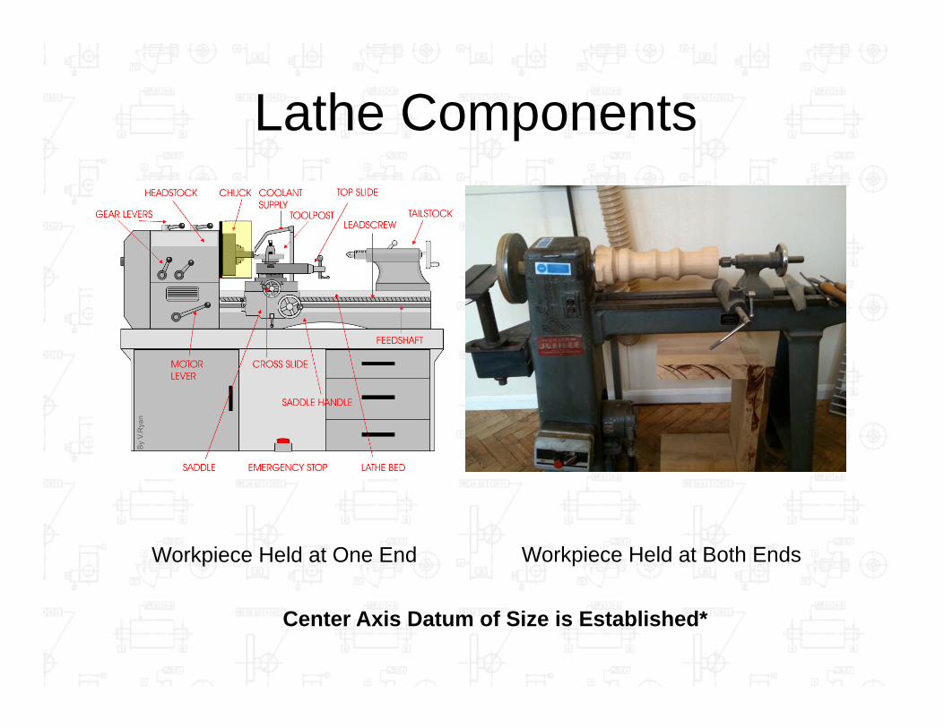
Lathe Components
Workpiece Held at One End Workpiece Held at Both Ends
Center Axis Datum of Size is Established*

Runout Controls– Very common– “Runout” is an error in “Eccentricity” and an
Inspection Method as well– Controls the functional relationship of surface
features referenced to an established datum axis (Cylindrical Datum of Size)*
– Always cylindrically-shaped features• Often for parts that will have to operate at a high RPM*• Eliminate Wobble and Vibration*• Usually created and inspected on a lathe*• Always turned 360°*• Generally Inspected with a Dial Indicator
– Able to control form, orientation and location*– Applied to a feature (not Feature of Size) & are RFS*
• Are not able to make use of the LMC or MMC Modifiers– Always references datum(s). Cylindrical Datum of
Size.*

Runout Indirect/Embedded Controls
(Circular Runout)

Runout Controls
–Can be applied to any surface on the feature
–Two Types

“If it Rotates or Vibrates, you probably want to put a Runout Tolerance on it”
(Circular Runout)
2D Zone, Independent Inspections*

Does Not Control Taper
(Circular Runout)
Because It can control Position

(Circular Runout)
(2D Zone)*
*

(Circular Runout)

*
*
(Datum Axis is Established)*
(Circular Runout)

Circular Runout– Individual/Independent checks
• Dial Indicator is “Reset”– 2-D zone
• Two concentric circles (for cylinders)• Two parallel planes (for flat end of
feature)– Datum of Size A is established in chuck or
collet– Part is rotated 360°– Dial indicator is kept perpendicular to
feature being inspected– FIM should not be greater that the
tolerance value

(Circular Runout)
(Part is Held at Both Ends on the Lathe)

(Circular Runout)

Total Runout3D Zone, Entire Surface is Inspected*
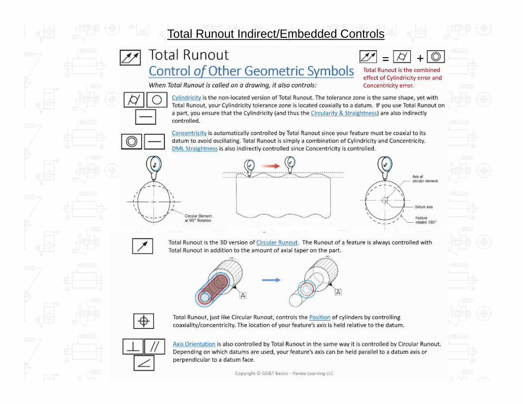
Total Runout Indirect/Embedded Controls
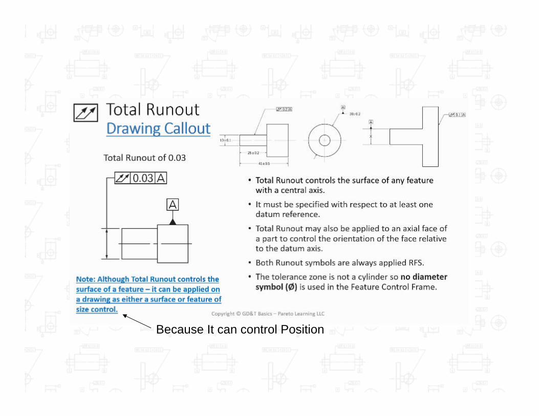
Because It can control Position

(3D Zone)*

Total Runout– Checks entire surface
•Dial indicator is swept from one end of the feature to the other
•Part is being rotated 360°•Virtual Axis Datum A – B is established between two centering pins
– 3-D Zone*•Two concentric cylinders (for cylinders)
•Two parallel planes (for perpendicular flat end of feature)
•FIM should not be greater that the tolerance value
Virtual Axis
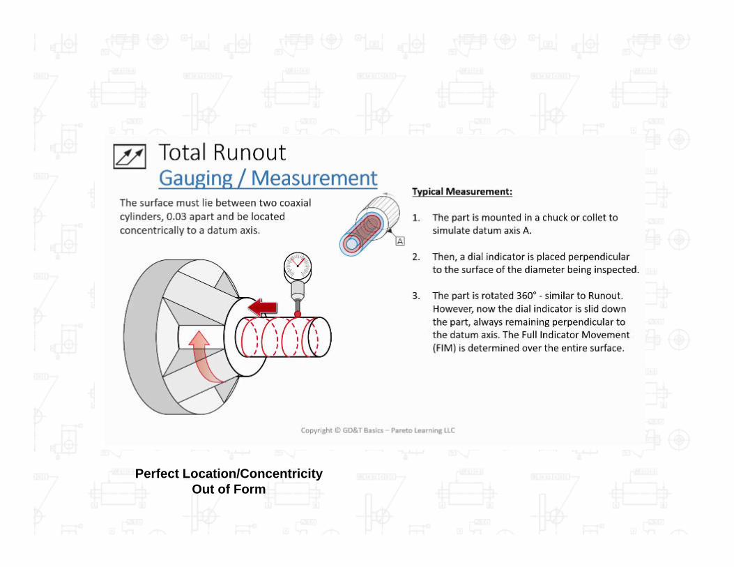
Perfect Location/ConcentricityOut of Form

Total Runout Controlling Perpendicularity
Flat End Surface is Controlled Perpendicular 0.1 to datum Axis AInspects for Perpendicularity and Flatness

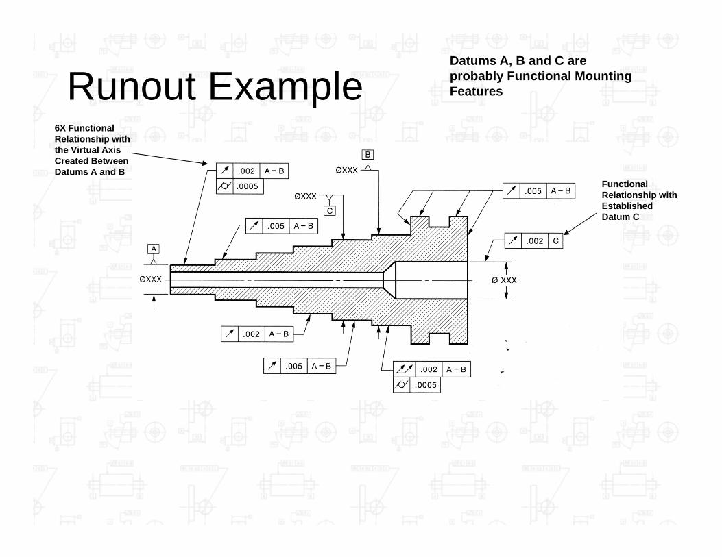
Runout Example6X Functional Relationship with the Virtual Axis Created Between Datums A and B
Datums A, B and C are probably Functional Mounting Features
Functional Relationship with Established Datum C