
Runoff Conveyance
116
Runoff Conveyance 4-117 Check Dam (CD) Practice Description A check dam is a small barrier or dam constructed across a swale, drainage ditch or other area of concentrated flow for the purpose of reducing channel erosion. Channel erosion is reduced because check dams flatten the gradient of the flow channel and slow the velocity of channel flow. Most check dams are constructed of rock, but hay bales, logs and other materials may be acceptable. Contrary to popular opinion, most check dams trap an insignificant volume of sediment. This practice applies in small open channels and drainageways, including temporary and permanent swales. It is not to be used in a live stream. Situations of use include areas in need of protection during establishment of grass and areas that cannot receive a temporary or permanent non-erodible lining for an extended period of time. Planning Considerations Check dams are used in concentrated flow areas to provide temporary channel stabilization during the intense runoff periods associated with construction disturbances. Check dams may be constructed of rock, logs, hay bales or other suitable material, including manufactured products. MDOT Drawing ECD-4 at the end of this practice shows the typical application of check dam structures. Most check dams are constructed of rock. Rock may not be acceptable in some installations because of aesthetics; therefore, alternative types of check dams need to be considered. Rock check dams Rock check dams (Figures CD-1 and CD-2) are usually installed with backhoes or other suitable equipment, but hand labor is likely needed to complete most installations to the quality needed. The rock is usually purchased, and some locations in the state may not have rock readily available. The use of rock should be considered carefully in areas to be
Transcript of Runoff Conveyance

Runoff Conveyance
4-117
Check Dam (CD)
Practice Description A check dam is a small barrier or dam constructed across a swale, drainage ditch or other area of concentrated flow for the purpose of reducing channel erosion. Channel erosion is reduced because check dams flatten the gradient of the flow channel and slow the velocity of channel flow. Most check dams are constructed of rock, but hay bales, logs and other materials may be acceptable. Contrary to popular opinion, most check dams trap an insignificant volume of sediment. This practice applies in small open channels and drainageways, including temporary and permanent swales. It is not to be used in a live stream. Situations of use include areas in need of protection during establishment of grass and areas that cannot receive a temporary or permanent non-erodible lining for an extended period of time.
Planning Considerations Check dams are used in concentrated flow areas to provide temporary channel stabilization during the intense runoff periods associated with construction disturbances. Check dams may be constructed of rock, logs, hay bales or other suitable material, including manufactured products. MDOT Drawing ECD-4 at the end of this practice shows the typical application of check dam structures. Most check dams are constructed of rock. Rock may not be acceptable in some installations because of aesthetics; therefore, alternative types of check dams need to be considered.
Rock check dams Rock check dams (Figures CD-1 and CD-2) are usually installed with backhoes or other suitable equipment, but hand labor is likely needed to complete most installations to the quality needed. The rock is usually purchased, and some locations in the state may not have rock readily available. The use of rock should be considered carefully in areas to be

Runoff Conveyance
4-118
mowed. Some rock may be washed away during heavy rain events and should be removed before each mowing operation. Additional installation drawings are provided at the end of this practice as MDOT Drawings ECD-8 and ECD-9.
Log check dams Log check dams (Figure CD-3) are more economical from a materials cost standpoint since logs can usually be salvaged from clearing operations. The time and labor required would be greater for log check dams. Increased labor costs would offset the reduced material costs. Log check dams would not be permanent but may last long enough to get grass linings established.
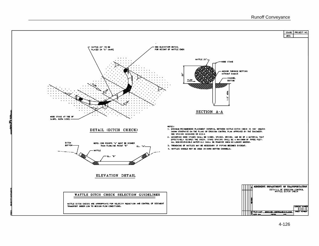
Hay bale check dams Check dams constructed of hay bales (Figure CD-4) have the shortest life of the materials discussed and are only used as a temporary means to help establish a channel to vegetation. MDOT Drawing ECD-5 is provided at the end of this practice and shows more specifics for hay bale check dams. MDOT Drawing ECD-6 shows typical details for a straw wattle ditch check as an alternative to hay bale check dams. Hay bale check dams should not be used where permanent watercourse protection is needed and should be used only in concentrated-flow areas where only minimal runoff occurs. Without proper installation, which is rarely done, hay bale check dams always fail.
Figure CD-1 Profile of Typical Rock Check Dams
Check dams should be planned to be compatible with the other features such as streets, walks, trails, sediment basins and rights-of-way or property lines. Check dams are normally constructed in series, and the dams should be located at a normal interval from other grade controls such as culverts or sediment basins.

Runoff Conveyance
4-119
Figure CD-2 Cross Section of Typical Rock Check Dam
Figure CD-3 Typical Log Check Dam

Runoff Conveyance
4-120
Figure CD-4 Typical Hay Bale Check Dam (NOTE: Without proper installation, which is rarely done, hay bale check dams always fail.)
Design Criteria and Installation Formal design is not required. The following limiting factors should be adhered to when designing check dams.
Drainage Area Ten acres or less (rock or logs).
Maximum Height Two feet when drainage area is less than 5 acres. Three feet when drainage area is 5 to 10 acres.
Depth of Flow Six inches when drainage area is less than 5 acres. Twelve inches when drainage area is 5 to 10 acres. The top of dam, perpendicular to flow, should be parabolic. The center of the dam should be constructed lower than the ends. The elevation of the center of the dam should be lower than the ends by the depth of flow listed above.
Side Slopes 2:1 or flatter.
Spacing Elevation of the toe of the upstream dam is at or below elevation of the crest of the downstream dam.

Runoff Conveyance
4-121
Keyway The rock or log check dam should be keyed into the channel bottom and abutments to a depth of 12 to 24″. The keyway width should be at least 12″. The keyway is to prevent erosion around the end of and beneath the dam. Hay bale check dams should be embedded into the soil at least 3″.
Rock Check Dams Rock check dams should be constructed of durable rock riprap. Rock material diameter should be 2″ to 15″. In soils where failure by piping of soils into the rock is likely, a geotextile will be used as a filter to separate the soils from the rock. Geotextile should conform to the requirements of type I geotextile in Table CD-1.
Table CD-1 Requirements for Nonwoven Geotextile
Property Test method
Class I Class II Class III Class IV 1
Tensile strength (lb) 2 ASTM D 4632
grab test
180 minimum 120 minimum 90 minimum 115 minimum
Elongation at failure (%) 2 ASTM D 4632 ≥ 50 ≥ 50 ≥ 50 ≥ 50
Puncture (pounds) ASTM D 4833 80 minimum 60 minimum 40 minimum 40 minimum
Ultraviolet light
(% residual tensile strength)
ASTM D 4355
150-hr exposure
70 minimum 70 minimum 70 minimum 70 minimum
Apparent opening size
(AOS)
ASTM D 4751 As specified
max. no.40 3
As specified
max. no.40 3
As specified
max. no.40 3
As specified
max. no.403
Permittivity sec–1 ASTM D 4491 0.70 minimum 0.70 minimum 0.70 minimum 0.10 minimum
Table copied from NRCS Material Specification 592.
1 Heat-bonded or resin-bonded geotextile may be used for Classes III and IV. They are particularly well suited to Class IV. Needle-punched geotextile is required for all other classes. 2 Minimum average roll value (weakest principal direction). 3 U.S. standard sieve size.

Runoff Conveyance
4-122
Site Preparation Determine location of any underground utilities. Locate and mark the site for each check dam in strategic locations (to avoid utilities and optimize effectiveness of each structure in flattening channel grade). Remove debris and other unsuitable material that would interfere with proper placement of the check dam materials. Excavate a shallow keyway (12″-24″ deep and at least 12″ wide) across the channel and into each abutment for each check dam.
Materials Installation As specified, install a non-woven geotextile fabric in the keyway in sandy or silty soils. This may not be required in clayey soils. Construct the dam with a minimum 2:1 side slope over the keyway and securely embed the dam into the channel banks. Position rock to form a parabolic top, perpendicular to channel flow, with the center portion at the elevation shown in the design so that the flow goes over the structure and not around the structure.
Erosion and Sediment Control Install vegetation (temporary or permanent seeding) or mulching to stabilize other areas disturbed during the construction activities.
Construction Verification Check finished size, grade and shape for compliance with standard drawings and materials list (check for compliance with specifications if included in contract specifications).
Common Problems Consult with a qualified design professional if any of the following occur:
Variations in topography on site indicate check dam will not function as intended. Change in plan will be needed. Materials specified in the plan are not available.
Maintenance Inspect the check dam for rock displacement and abutments for erosion around the ends of the dam after each significant rainfall event. If the rock appears too small, add additional stone and use a larger size. Inspect the channel after each significant rainfall event. If channel erosion exceeds expectations, consult with the design professional and consider adding another check dam to reduce channel flow grade.
Runoff Conveyance
4-123
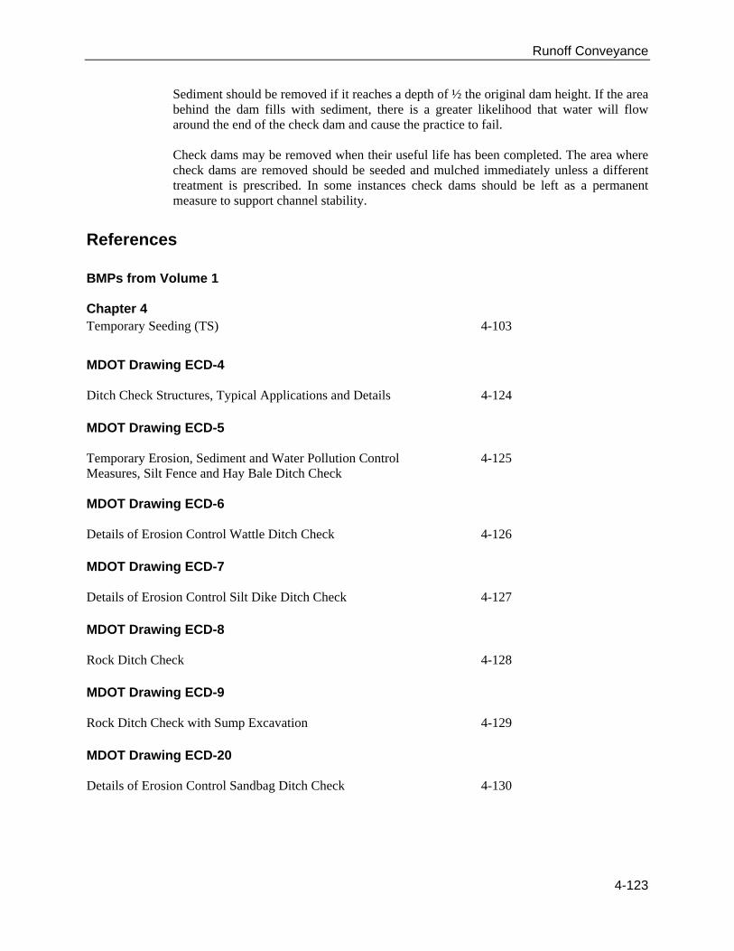
Sediment should be removed if it reaches a depth of ½ the original dam height. If the area behind the dam fills with sediment, there is a greater likelihood that water will flow around the end of the check dam and cause the practice to fail. Check dams may be removed when their useful life has been completed. The area where check dams are removed should be seeded and mulched immediately unless a different treatment is prescribed. In some instances check dams should be left as a permanent measure to support channel stability.
References
BMPs from Volume 1 Chapter 4 Temporary Seeding (TS) 4-103
MDOT Drawing ECD-4 Ditch Check Structures, Typical Applications and Details 4-124
MDOT Drawing ECD-5 Temporary Erosion, Sediment and Water Pollution Control Measures, Silt Fence and Hay Bale Ditch Check
4-125
MDOT Drawing ECD-6 Details of Erosion Control Wattle Ditch Check 4-126
MDOT Drawing ECD-7 Details of Erosion Control Silt Dike Ditch Check 4-127 MDOT Drawing ECD-8 Rock Ditch Check 4-128
MDOT Drawing ECD-9 Rock Ditch Check with Sump Excavation 4-129
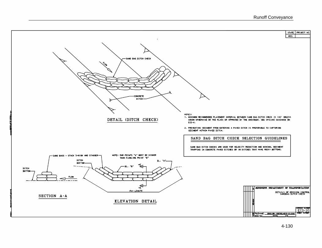
MDOT Drawing ECD-20 Details of Erosion Control Sandbag Ditch Check 4-130

Runoff Conveyance
4-124

Runoff Conveyance
4-125
Runoff Conveyance
4-126

Runoff Conveyance
4-127

Runoff Conveyance
4-128

Runoff Conveyance
4-129
Runoff Conveyance
4-130

Runoff Conveyance
4-131
Diversion (DV)
Practice Description A diversion is a watercourse constructed across a slope consisting of an excavated channel, a compacted ridge, or a combination of both. Most diversions are constructed by excavating a channel and using the excavated material to construct a ridge on the downslope side of the channel. Right-of-way diversions and temporary diversions are sometimes constructed by making a ridge, often called a berm, from fill material. This practice applies to sites where stormwater runoff can be redirected to permanently protect structures or areas downslope from erosion, sediment, and excessive wetness or localized flooding. Diversions may be used to temporarily divert stormwater runoff to protect disturbed areas and slopes or to retain sediment on-site during construction. Perimeter protection is sometimes used to describe both permanent and temporary diversions used at either the upslope or downslope side of a construction area. Right-of-way diversions, sometimes referred to as water bars, are used to shorten the flow length on a sloping right-of-way and reduce the erosion potential of the stormwater runoff.
Water Bar

Runoff Conveyance
4-132
Planning Considerations Diversions are designed to intercept and carry excess water to a stable outlet.
Diversions can be useful tools for managing surface water flows and preventing soil erosion. On moderately sloping areas, they may be placed at intervals to trap and divert sheet flow before it has a chance to concentrate and cause rill and gully erosion. Simple water bars illustrate this concept (Figure DV-1). Diversions may be placed at the top of cut or fill slopes to keep runoff from upgradient drainage areas off the slope. Diversions are also typically built at the base of steeper slopes to protect flatter developed areas that cannot withstand runoff water from outside areas. They can also be used to protect structures, parking lots, adjacent properties, and other special areas from flooding. Diversions are preferable to other types of man-made stormwater conveyance systems because they more closely simulate natural flow patterns and characteristics. Flow velocities are generally kept to a minimum. When properly coordinated into the landscape design of a site, diversions can he visually pleasing as well as functional. As with any earthen structure, it is very important to establish adequate vegetation as soon as possible after installation. It is usually important to stabilize the drainage area above the diversion so that sediment will not enter and accumulate in the diversion channel.
Figure DV-1 Water Bar
Runoff Conveyance
4-133
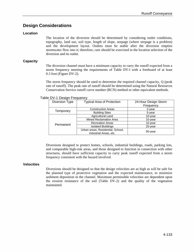
Design Considerations
Location The location of the diversion should be determined by considering outlet conditions, topography, land use, soil type, length of slope, seepage (where seepage is a problem) and the development layout. Outlets must be stable after the diversion empties stormwater flow into it; therefore, care should be exercised in the location selection of the diversion and its outlet.
Capacity The diversion channel must have a minimum capacity to carry the runoff expected from a storm frequency meeting the requirements of Table DV-l with a freeboard of at least 0.3 foot (Figure DV-2). The storm frequency should be used to determine the required channel capacity, Q (peak rate of runoff). The peak rate of runoff should be determined using the Natural Resources Conservation Service runoff curve number (RCN) method or other equivalent methods.
Table DV-1 Design Frequency Diversion Type Typical Area of Protection 24-Hour Design Storm
Frequency
Temporary Construction Areas 2-year
Building Sites 5-year
Permanent
Agricultural Land 10-year Mined Reclamation Area 10-year
Recreation Areas 10-year Isolated Buildings 25-year
Urban areas, Residential, School, Industrial Areas, etc.
50-year
Diversions designed to protect homes, schools, industrial buildings, roads, parking lots, and comparable high-risk areas, and those designed to function in connection with other structures, should have sufficient capacity to carry peak runoff expected from a storm frequency consistent with the hazard involved.
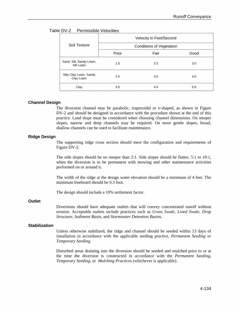
Velocities Diversions should be designed so that the design velocities are as high as will be safe for the planned type of protective vegetation and the expected maintenance, to minimize sediment deposition in the channel. Maximum permissible velocities are dependent upon the erosion resistance of the soil (Table DV-2) and the quality of the vegetation maintained.
Runoff Conveyance
4-134
Table DV-2 Permissible Velocities
Soil Texture
Velocity in Feet/Second
Conditions of Vegetation
Poor Fair Good
Sand, Silt, Sandy Loam, Silt Loam
1.5 2.0 3.0
Silty Clay Loam, Sandy Clay Loam
2.5 3.0 4.0
Clay 3.0 4.0 5.0
Channel Design The diversion channel may be parabolic, trapezoidal or v-shaped, as shown in Figure DV-2 and should be designed in accordance with the procedure shown at the end of this practice. Land slope must be considered when choosing channel dimensions. On steeper slopes, narrow and deep channels may be required. On more gentle slopes, broad, shallow channels can be used to facilitate maintenance.
Ridge Design The supporting ridge cross section should meet the configuration and requirements of Figure DV-2. The side slopes should be no steeper than 2:1. Side slopes should be flatter, 5:1 to 10:1, when the diversion is to be permanent with mowing and other maintenance activities performed on or around it.
The width of the ridge at the design water elevation should be a minimum of 4 feet. The minimum freeboard should be 0.3 foot. The design should include a 10% settlement factor.
Outlet Diversions should have adequate outlets that will convey concentrated runoff without erosion. Acceptable outlets include practices such as Grass Swale, Lined Swale, Drop Structure, Sediment Basin, and Stormwater Detention Basins.
Stabilization Unless otherwise stabilized, the ridge and channel should be seeded within 13 days of installation in accordance with the applicable seeding practice, Permanent Seeding or Temporary Seeding. Disturbed areas draining into the diversion should be seeded and mulched prior to or at the time the diversion is constructed in accordance with the Permanent Seeding, Temporary Seeding, or Mulching Practices (whichever is applicable).

Runoff Conveyance
4-135
Figure DV-2 Typical Diversions Detail

Runoff Conveyance
4-136
Figure DV-3 Water Bar Detail
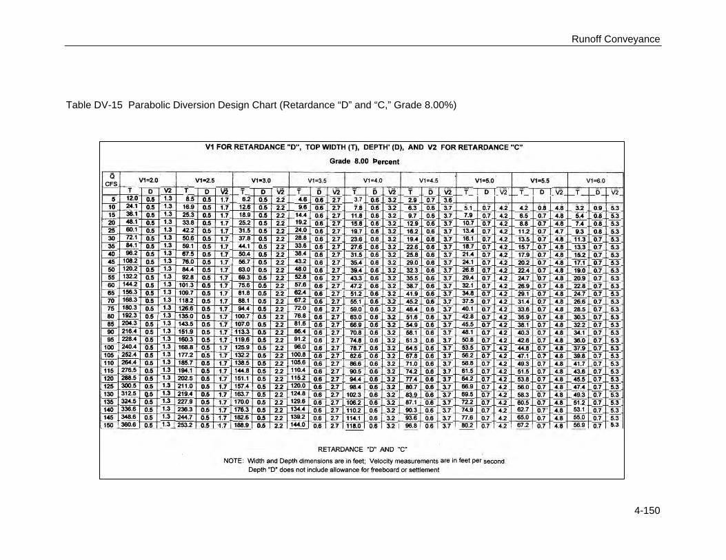
Design Criteria Tables DV-l through DV-16 may be used to facilitate the design of grass-lined diversions with parabolic cross sections. These tables are based on a retardance of “D” (vegetation newly cut) to determine V1 for stability considerations. To determine channel capacity, choose a retardance of “C” when proper maintenance is expected; otherwise, design channel capacity based on retardance “B.” Refer to Table DV-2 for maximum permissible velocities. The permissible velocities guide the selection of V1 and should not be exceeded. It is good practice to use a value for V1 that is significantly less than the maximum allowable when choosing a design cross section. When velocities approach the

Runoff Conveyance
4-137
maximum allowable, flatter grades should be evaluated or a more erosion-resistant liner such as erosion control blanket or riprap should be considered. After the diversion dimensions are selected in the design tables, the top width should be increased by 4 feet and the depth by 0.3 foot for freeboard.
Example Problem
Given Q: 30 cfs Grade: 1% Soil: Sandy clay loam Condition of vegetation expected: fair Maintenance: low; will be cut only twice a year. Site will allow a top width of 26 feet.
Find Diversion top width and depth that will be stable and fit site conditions.
Solution From Table DV-2, use maximum permissible velocity of 3.0 ft/sec. Since maintenance will be low, use “B” retardance for capacity. From Table DV-4, use retardance “D” and “B”; Grade 1.00 Percent Top width = 21.0 feet + 4 feet = 25.0 feet. Depth = 1.6 feet + 0.3 foot = 1.9 feet. V2 = 1.3 ft/sec. Note: V1 < 3.0 ft/sec.; Top width < 26 feet, design O.K.
Note: It is good practice to select a cross section that will give a velocity, V1, well below the maximum allowable whenever site conditions permit. Wide, shallow cross sections are more stable and require less maintenance. It is always prudent to evaluate flatter design grades in order to best fit diversions to the site and keep velocities well below maximum allowable.

Runoff Conveyance
4-138
Table DV-3 Parabolic Diversion Design Chart (Retardance “D” and “B,” Grade 0.50%)

Runoff Conveyance
4-139
Table DV-4 Parabolic Diversion Design Char (Retardance “D” and “B,” Grade 1.00%)

Runoff Conveyance
4-140
Table DV-5 Parabolic Diversion Design Chart (Retardance “D” and “B,” Grade 2.00%)

Runoff Conveyance
4-141
Table DV-6 Parabolic Diversion Design Chart (Retardance “D” and “B,” Grade 4.00%)

Runoff Conveyance
4-142
Table DV-7 Parabolic Diversion Design Chart (Retardance “D” and “B,” Grade 6.00%)

Runoff Conveyance
4-143
Table DV-8 Parabolic Diversion Design Chart (Retardance “D” and “B,” Grade 8.00%)

Runoff Conveyance
4-144
Table DV-9 Parabolic Diversion Design Chart (Retardance “D” and “B,” Grade 10.00%)

Runoff Conveyance
4-145
Table DV-10 Parabolic Diversion Design Chart (Retardance “D” and “C,” Grade .50%)

Runoff Conveyance
4-146
Table DV-11 Parabolic Diversion Design Chart (Retardance “D” and “C,” Grade 1.00%)

Runoff Conveyance
4-147
Table DV-12 Parabolic Diversion Design Chart (Retardance “D” and “C,” Grade 2.00%)

Runoff Conveyance
4-148
Table DV-13 Parabolic Diversion Design Chart (Retardance “D” and “C,” Grade 4.00%)

Runoff Conveyance
4-149
Table DV-14 Parabolic Diversion Design Chart (Retardance “D” and “C,” Grade 6.00%)
Runoff Conveyance
4-150
Table DV-15 Parabolic Diversion Design Chart (Retardance “D” and “C,” Grade 8.00%)

Runoff Conveyance
4-151
Table DV-16 Parabolic Diversion Design Chart (Retardance “D” and “C,” Grade 10.00%)

Runoff Conveyance
4-152
Construction Prior to start of construction, diversions should be designed by a qualified design professional. Plans and specifications should be referred to by field personnel throughout the construction process. A diversion should be built according to planned alignment, grade and cross section. Typically, a diversion is constructed with the following activities.
Site Preparation Determine exact location of any underground utilities (see Appendix C: MS One-Call and 811 Color Coding). Locate and mark the alignment of the diversion as shown on the plans. Minor adjustments to the grade and alignment may be required to meet site conditions. The alignment should maintain a positive grade toward the outlet and end in a stable outlet or an area that can be stabilized. Clear the construction area of trees, stumps, brush, sod and other unsuitable material which would interfere with compaction of the ridge. Disk or scarify the area where the ridge is to be installed before placing the fill. Clean out and refill with compacted earth fill all ditches, swales or gullies to be crossed. Apply gravel or hard surface protection at vehicle crossings to prevent rutting. Install stable outlets prior to construction. Adequate vegetation should be established in the outlet channel. If vegetation cannot be established, use Erosion Control Blankets and/or Rock Outlets or Outlet Protection.
Grading Excavate, fill and shape the diversion to planned alignment, grade and cross section. The channel should have a positive grade toward the outlet to avoid ponding. Where possible, blend diversion into the surrounding landscape. Overfill and compact the ridge, allowing for 10% settlement. Fill should be placed in lifts of no more than 6″ to 8″ in depth. Compaction may be achieved by driving wheeled equipment along the ridge as lifts are added. The settled ridge top must be at or above design elevation at all points. All earth removed and not needed for the practice should be spread or disposed of so that it will not interfere with the functioning of the diversion.
Erosion and Sediment Control Control sediment along grading limits with sediment control measures. Leave sufficient area adjacent to the diversion to permit clean-out and regrading. Immediately after installation, install vegetation treatment or other means to stabilize the diversion in accordance with plans. Install gravel or hard surface protection at vehicle crossings.
Runoff Conveyance
4-153
Stabilize diversion outlets in accordance with plans.
Construction Verification Check finished grades and cross section of diversions to eliminate constrictions to flow. Check all ridges for low spots and stability.
Common Problems Consult with a qualified design professional if any of the following occur:
Variations in topography on site indicate diversion will not function as intended. Changes in plans will be needed. Design specifications for seed variety or seeding cannot be met. Substitutions not approved by the design professional could result in erosion and lead to diversion failure. Seepage is encountered during construction. It may be necessary to install drains.
Maintenance Inspect weekly and following each storm event for erosion until the diversion is vegetated. Remove debris and sediment from the channel, and rebuild the ridge to design elevation where needed. Check diversion outlet for erosion and repair if area becomes unstable. Maintain vegetation with periodic fertilization and mowing to keep vegetation in a vigorous, healthy condition. Mow for weed and brush control during the first year and as needed to prevent brush and tree seedlings from becoming established after the first year of installation. When the work area has been stabilized, remove temporary diversions, sediment barriers and traps, and repair bare or damaged areas in the vegetation by planting and mulching or sodding. Stabilize all eroded, rutted or disturbed areas as soon as possible with vegetation or synthetic erosion control measures as specified in the design.

Runoff Conveyance
4-154
References
BMPs from Volume 1 Chapter 4 Permanent Seeding (PS) 4-53 Temporary Seeding (TS) 4-103 Drop Structure (DS) 4-156 Grass Swale (GS) 4-162 Lined Swale (LS) 4-190 Sediment Basin (SBN) 4-298
MDOT Drawing TEC-2
Typical Temporary Erosion Control Measures (Temporary Shoulder Berm)
4-155

Runoff Conveyance
4-155
Runoff Conveyance
4-156
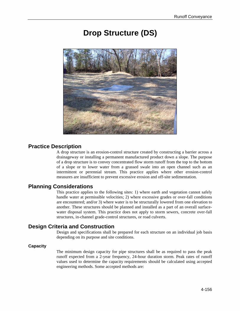
Drop Structure (DS)
Practice Description A drop structure is an erosion-control structure created by constructing a barrier across a drainageway or installing a permanent manufactured product down a slope. The purpose of a drop structure is to convey concentrated flow storm runoff from the top to the bottom of a slope or to lower water from a grassed swale into an open channel such as an intermittent or perennial stream. This practice applies where other erosion-control measures are insufficient to prevent excessive erosion and off-site sedimentation.
Planning Considerations This practice applies to the following sites: 1) where earth and vegetation cannot safely handle water at permissible velocities; 2) where excessive grades or over-fall conditions are encountered; and/or 3) where water is to be structurally lowered from one elevation to another. These structures should be planned and installed as a part of an overall surface-water disposal system. This practice does not apply to storm sewers, concrete over-fall structures, in-channel grade-control structures, or road culverts.
Design Criteria and Construction Design and specifications shall be prepared for each structure on an individual job basis depending on its purpose and site conditions.
Capacity The minimum design capacity for pipe structures shall be as required to pass the peak runoff expected from a 2-year frequency, 24-hour duration storm. Peak rates of runoff values used to determine the capacity requirements should be calculated using accepted engineering methods. Some accepted methods are:

Runoff Conveyance
4-157
Natural Resources Conservation Service, National Engineering Handbook Series, Part 650, Engineering Field Handbook, Chapter 2, Estimating Runoff.
Natural Resources Conservation Service (formerly Soil Conservation Service),
Technical Release 55, Urban Hydrology for Small Watersheds. Other comparable methods – See Appendix A: Erosion and Stormwater Runoff
Calculations found in the Appendices Volume.
Runoff computation will be based upon the most severe soil and cover conditions that will exist in the area draining into the pipe structures during the planned life of the structure. All pipe structures should be designed as island type with an emergency spillway to safely pass storm runoff greater than the structure design storm. The minimum total capacity of the principal and emergency spillways shall be that required to handle the 25-year 24-hour duration storm, or the peak rate of flow from the contributing structure, whichever is greater.
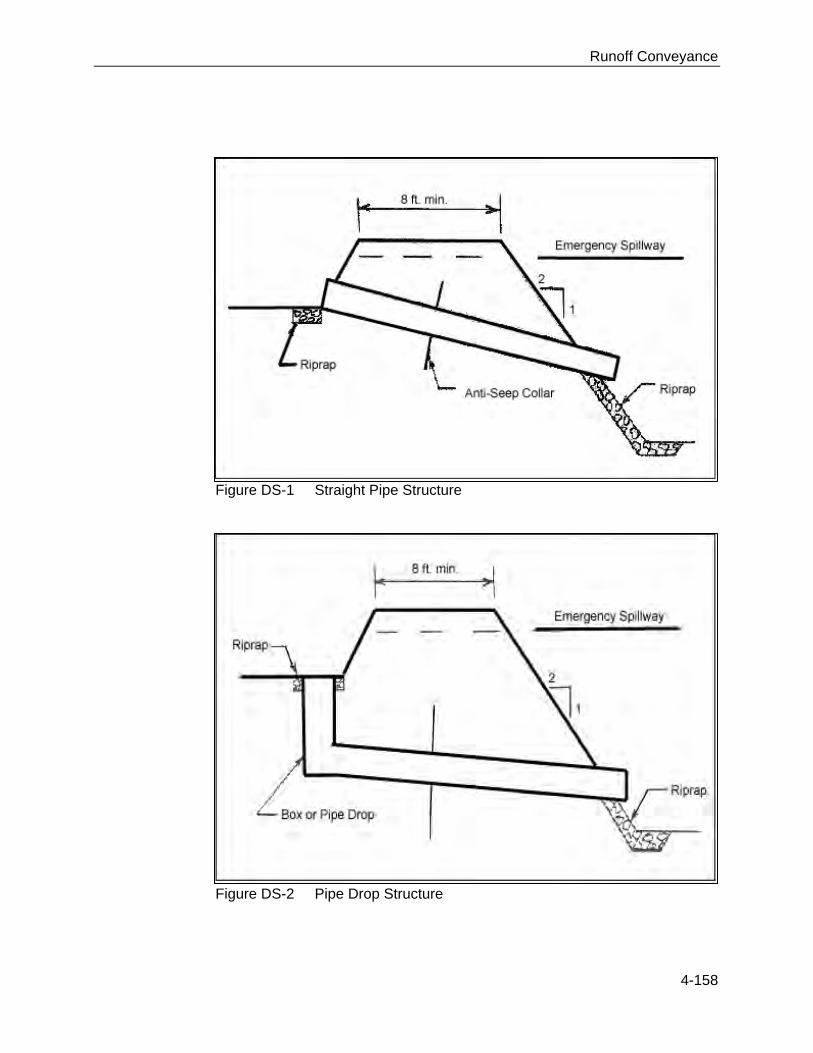
General The planning and design of antivortex devices, trash racks, and anti-seep collars should be in accordance with the requirements for principal spillway pipe design in the Sediment Basin Practice. Outlet protection should be designed according to the Outlet Protection Practice. The crest elevation for the emergency spillway shall be set at the minimum level necessary to ensure full pipe flow of the principal spillway. The top of the settled embankment shall be based on 1 foot of freeboard above the design flow depth in the emergency spillway. Straight pipe structures should be built in accordance with Figure DS-l. Pipe drop structures should be built in accordance with Figure DS-2.
Runoff Conveyance
4-158
Figure DS-1 Straight Pipe Structure
Figure DS-2 Pipe Drop Structure

Runoff Conveyance
4-159
Construction Prior to the start of construction, drop structures should be designed by a qualified design professional. Plans and specifications should be referred to by field personnel throughout the construction process. The drop structure should be built according to planned grades and dimensions. Note: Construction of an embankment with spillways is the only type of drop structure covered in this edition of the manual. Consider the following guidance as construction proceeds:
Site Preparation Locate all utilities at the site to ensure avoidance (See Appendix C: MS One-Call and 811 Color Coding). Clear, grub, and strip the dam foundation and emergency spillway area, removing all woody vegetation, rocks and other objectionable material. Dispose of trees, limbs, logs, and other debris in designated disposal areas. Stockpile surface soil for use later during topsoiling. Clear the sediment pool to facilitate sediment clean-out and dispose of trees, limbs, logs, and other debris in designated disposal areas.
Principal Spillway Prepare the pipe bedding and situate the spillway barrel (pipe) on a firm, even foundation. Install anti-seep collars according to the design plan. Place around the barrel 4″ layers of moist, clayey, workable soil (not pervious material such as sand, gravel or silt), and compact with hand tampers to at least the density of the foundation soil. (Do not raise the pipe from the foundation when compacting under the pipe haunches.) At the pipe inlet, install Inlet Protection according to the design plan. At the pipe outlet, install Outlet Protection according to the design plan (if not specific, use a riprap apron at least 5 feet wide to a stable grade).
Embankment Scarify the foundation of the dam before placing fill. Use fill from predetermined borrow areas. It should be clean, stable soil free of roots, woody vegetation, rocks and other debris, and must be wet enough to form a ball without crumbling, yet not so wet that water can be squeezed out. Place the most permeable soil in the downstream toe and the least permeable in the center portion of the dam.

Runoff Conveyance
4-160
Protect the spillway barrel with 2 feet of fill that has been compacted with hand tampers before traversing over the pipe with equipment. Compact the fill material in 6″ to 8″ continuous layers over the length of the embankment. One way is by routing construction equipment so that each layer is traversed by at least one wheel of the equipment. Construct and compact the embankment to an elevation 10% above the design height to allow for settling. The embankment should have a minimum 8-foot top width and 3:1 (Horizontal: Vertical) side slopes, but the design may specify additional width and gentler side slopes.
Emergency Spillway Construct the spillway at the site located by the qualified design professional according to the plan design (in undisturbed soil around one end of the embankment, and so that any flow will return to the receiving channel without damaging the embankment).
Erosion Control Minimize the size of all disturbed areas. Use temporary diversions to prevent surface water from running onto disturbed areas. Vegetate and stabilize the embankment, the emergency spillway and all disturbed areas immediately after construction.
Construction Verification Check the finished grades and configuration for all earthwork. Check elevations and dimensions of all pipes and structures.
Common Problems Consult with a qualified design professional if any of the following occur:
Variations in topography on site indicate drop structure will not function as intended. Seepage is encountered during construction; it may be necessary to install drains. Design specifications for fill, pipe, seed variety or seeding dates cannot be met; substitutions may be required. Unapproved substitutions could lead to failure.
Maintenance Inspect the drop structure after each storm event until it is completely stabilized with vegetation. Periodically check the embankment, emergency spillway and outlet for erosion damage, piping, settling, seepage or slumping along the toe or around the barrel and repair immediately.

Runoff Conveyance
4-161
References
BMPs from Volume 1 Chapter 4 Outlet Protection (OP) 4-199 Block and Gravel Inlet Protection (BIP) 4-233 Excavated Inlet Protection (EIP) 4-239 Fabric Drop Inlet Protection (FIP) 4-243 Straw Bale Inlet Protection (SBIP) 4-249

Runoff Conveyance
4-162
Grass Swale (GS)
Practice Description A grass swale is a natural or constructed channel that is shaped or graded to required dimensions and established with suitable vegetation for the stable conveyance of runoff without causing damage to the channel by erosion. This practice applies to the following sites: 1) where concentrated runoff will cause erosion damage; 2) a vegetative lining provides sufficient stability for the channel as designed; and/or 3) space is available for a relatively large cross section. Typical situations where concentrated-flow areas are addressed with a grass swale include roadside ditches, channels at property boundaries, outlets for diversions and other concentrated-flow areas subject to channel erosion. Grassed swales are generally considered permanent structures but may be used as a temporary measure. Grassed swales as permanent structures are discussed further in Chapter 4 of Volume 2 - Stormwater Management Manual.
Planning Considerations Grass swales should be carefully built to the design cross section, shape, and dimensions specified. Swales are hydraulic structures and as such depend upon the hydraulic parameters to function satisfactorily. Vegetated swales should be well established before large flows are permitted in the channel. The design of a channel cross section and lining is based primarily upon the volume and velocity of flow expected in the channel. This practice covers grassed swales with low- velocity flows (generally less than 5 ft/sec). Where high velocities are anticipated, lined swales should be used (see Lined Swale Practice or Riprap-lined Swale Practice). Lined swales should also be used where there is continuous flow in the swale, which would prevent establishment of vegetation within the flow area.
Runoff Conveyance
4-163
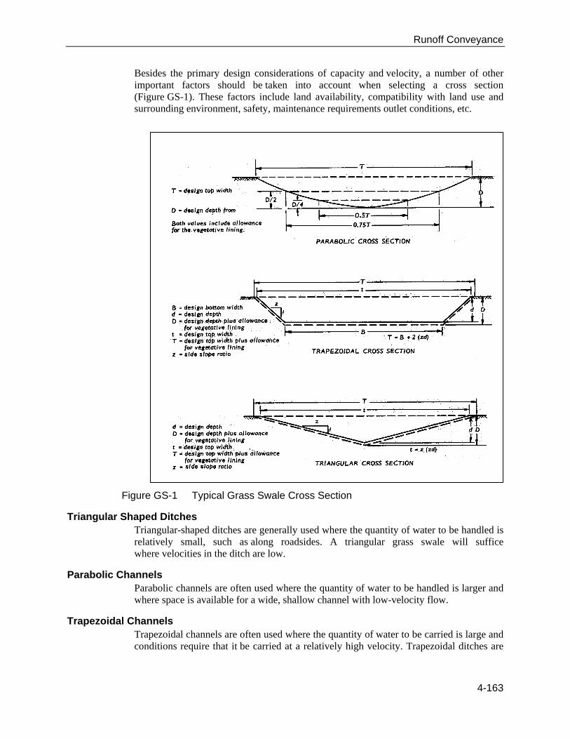
Besides the primary design considerations of capacity and velocity, a number of other important factors should be taken into account when selecting a cross section (Figure GS-1). These factors include land availability, compatibility with land use and surrounding environment, safety, maintenance requirements outlet conditions, etc.
Figure GS-1 Typical Grass Swale Cross Section
Triangular Shaped Ditches Triangular-shaped ditches are generally used where the quantity of water to be handled is relatively small, such as along roadsides. A triangular grass swale will suffice where velocities in the ditch are low.
Parabolic Channels Parabolic channels are often used where the quantity of water to be handled is larger and where space is available for a wide, shallow channel with low-velocity flow.
Trapezoidal Channels Trapezoidal channels are often used where the quantity of water to be carried is large and conditions require that it be carried at a relatively high velocity. Trapezoidal ditches are

Runoff Conveyance
4-164
generally lined with concrete or riprap, but in some cases can be grassed swales, if lined with erosion control blankets (see Erosion Control Blanket Practice).
Other Considerations Outlet conditions for all channels should be considered. Appropriate measures must be taken to dissipate the energy of the flow to prevent scour at the outlet of the swale.
Grass swales should be protected from erosion by concentrated flows. The methods of protecting grass swales would include, but not be limited to, the following:
Vegetation. A combination of biodegradable linings and vegetation.
The type and intensity of the protective linings will determine the design of the grass swale. If velocities exceed stable velocities, for vegetated swales or vegetation with biodegradable linings, then other linings should be used (see Lined Swale or Riprap-lined Swale Practice). The time of the year should be considered when planning grass swales. Grass swales that are seeded to establish vegetation should not be planned for construction during late fall, winter or early spring. Grass swales constructed during mid-summer to early fall may need temporary seeding followed by permanent seeding at the recommended times. The vegetation species should be recommended for the area of the state that it is planned.
Design Criteria
Capacity Grass swales shall be designed to convey the peak rate of runoff as shown in Table GS-1. Adjustments should be made for release rates from structures and other drainage facilities. Grass swales shall also be designed to comply with local stormwater ordinances. Grass swales should be designed for greater capacity whenever there is danger of flooding or out-of-bank flow cannot be tolerated.
Table GS-1 Design Frequency for Grassed Swale
Grass Swale Type
Typical Area of Protection 24-Hour Design Storm Frequency
Temporary Construction Areas 2-year
Building Sites 5-year
Permanent
Agricultural Land 10-year Mined Reclamation Area 10-year
Recreation Areas 10-year Isolated Buildings 10-year
Urban areas, Residential, School, Industrial Areas, etc.
10-year
Peak rates of runoff values used to determine the capacity requirements should be calculated using accepted engineering methods. Some accepted methods are:

Runoff Conveyance
4-165
Natural Resources Conservation Service, National Engineering Handbook Series,
Part 650, Engineering Field Handbook, Chapter 2, Estimating Runoff. Natural Resources Conservation Service (formerly Soil Conservation Service),
Technical Release 55, Urban Hydrology for Small Watersheds. Other comparable methods – See Appendix A: Erosion and Stormwater Runoff
Calculations found in the Appendices Volume.
Grade of Grass Swale After selecting a location for the grassed swale that will minimize the impacts to the site and maximize the intended use, the grade in the grass swales should be determined. The grade in feet per 100 feet of length can be determined from a topographic map of the site or from a detailed survey of the planned grassed swale location.
Retardance The type grass used to vegetate the grassed swale and the degree of maintenance planned for the vegetation determine the retardance of the swale (see Table GS-2). Generally, the retardance used for the design of grassed swales should be “D” and “C” to produce a stable velocity and adequate capacity to carry the design storm.

Runoff Conveyance
4-166
Table GS-2 Retardance for Grassed Swales Retardance Species Cover Condition
A Reed Canarygrass Excellent stand, tall (average 36″)
Yellow Bluestem Ischaemum Excellent stand, tall (average 36″)
B
Smooth Bromegrass Good stand, mowed (average 12 to 15″) Bermuda Grass Good stand, tall (average 12″)
Native Grass Mixture (Little Bluestem, Blue Grama, and other long and short Midwest Grasses)
Good stand, unmowed
Tall Fescue Good stand, unmowed (average 18″) Lespedeza sericea Good stand, not woody, tall (average 19″) Grass-Legume mixture-Timothy, Smooth Bromegrass, or Orchardgrass
Good stand, uncut (average 20″)
Reed Canarygrass Good stand, mowed (average 12 to 15″) Tall Fescue, with Bird’s Foot Trefoil or Ladino Clover
Good stand, uncut (average 18″)
Blue Grama Good stand, uncut (average 13″)
C
Bahiagrass Good stand, uncut (average 6 to 8″) Bermuda Grass Good stand, mowed (average 6″) Redtop Good stand, headed (15 to 20″) Grass-Legume Mixture-Summer (Orchardgrass, Redtop, Italian Ryegrass, and Common Lespedeza)
Good stand, uncut (6 to 8″)
Centipede grass Very dense cover (average 6″) Kentucky Bluegrass Good stand, headed (6 to 12″)
D
Bermuda Grass Good stand, cut to 2.5″ height Red Fescue Good stand, headed (12 to 18″) Buffalo Grass Good stand, uncut (3 to 6″) Grass-Legume Mixture-fall, spring (Orchard Grass, Redtop, Italian Ryegrass, and Common Lespedeza)
Good stand, uncut (4 to 5″)
Lespedeza sericea After cutting to 2″ height. Very good stand before cutting
E Bermuda Grass Good stand, cut to 1.5″ height.
Bermuda Grass Burned stubble
Velocities Classify the soil where the swale is to be constructed into erosion-resistant cohesive (clayey) fine and coarse-grained soils or easily eroded noncohesive silt, clays and sands. Determine the type of vegetative cover to be established in the swale. Use the swale grade, cover, and soil erodibility to determine permissible velocity using Table GS-3.
Swale Dimensions The swale may be triangular shaped, parabolic or trapezoidal, as discussed in the planning considerations of this practice and shown in Figure GS-1.

Runoff Conveyance
4-167
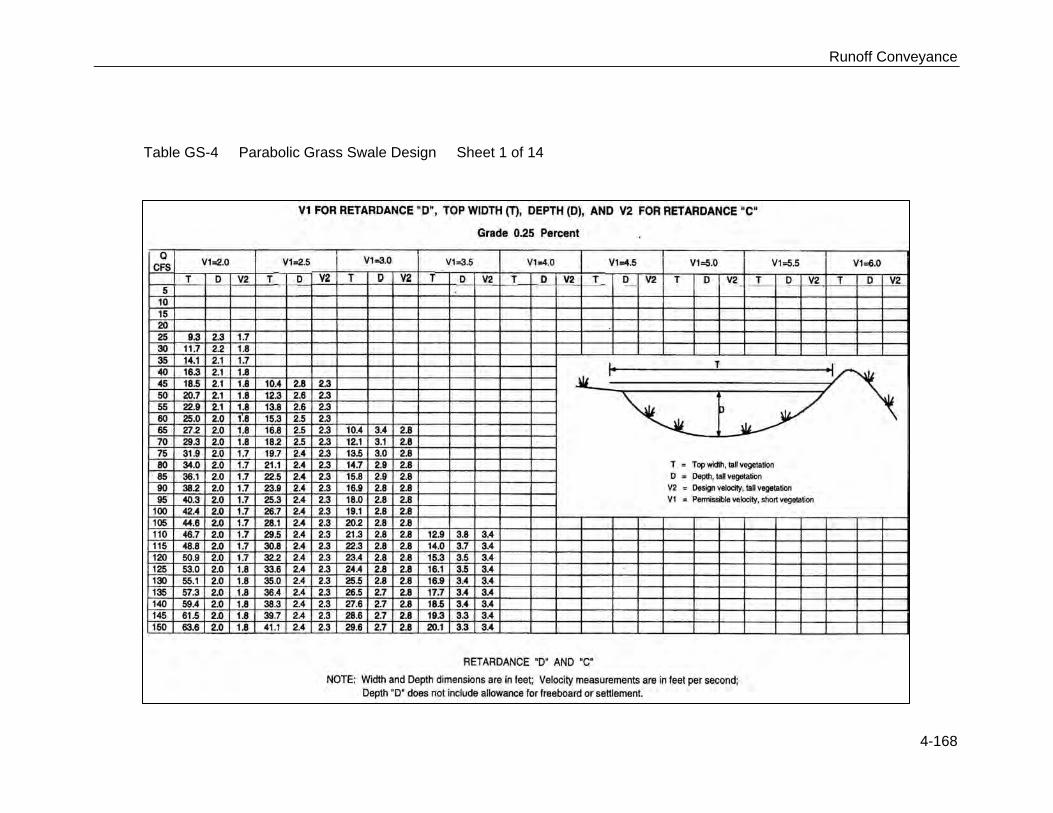
Using the peak discharge, swale grade, permissible velocity and retardance, the parabolic dimensions can be determined using Table GS-4 (Sheets 1 through 14).
Table GS-3 Permissible Velocities in Grassed Swales
Permissible Velocity1
Cover Slope Range2 Erosion-Resistant Soils3 (clayey)
Easily Eroded Soils4 (sandy)
percent ft/sec ft/sec
Bermuda Grass <5
5-10 over 10
8 7 6
6 4 3
Bahiagrass Tall Fescue
<5 5-10
over 10
7 6 5
5 4 3
Sericea lespedeza Weeping Lovegrass
<55
3.5
2.5
1 Use velocities exceeding (5ft/sec) only where good covers and proper maintenance can be obtained. 2 Do not use on slopes steeper than 10 percent except for vegetated side slopes in combination with a stone, concrete, or highly resistant vegetative center section. 3 Cohesive (clayey) fine-grain soils and coarse-grain soils with cohesive fines with a plasticity index of 10 to 40 (CL, CH, SC, and CG). 4 Soils that do not meet requirements for erosion-resistant soils. 5 Do not use on slopes steeper than 5 percent except for vegetated side slopes in combination with a stone, concrete, or highly resistant vegetative center section.
Design dimensions for triangular-shaped and trapezoidal-shaped swales can be determined using Manning’s equation or other accepted engineering designs. (See Appendix A: Channel Geometry.) The design water surface elevation of a channel receiving water from other tributary sources shall be equal to or less than the design water surface elevation of the contributing source. The design water surface elevation of contributing and receiving waters should be the same, whenever practical. A minimum depth may be necessary to provide adequate outlets for subsurface drains and tributary channels.
Drainage Polyethylene drainage tubing, tile, or other suitable subsurface drainage measures shall be provided for sites having high water tables or seepage problems.
Freeboard The minimum freeboard is 0.25 foot in depth. Freeboard is not required on grass swales with less than 1% slope and where out-of-bank flow will not be damaging and can be tolerated in the normal operation at the site.
Runoff Conveyance
4-168
Table GS-4 Parabolic Grass Swale Design Sheet 1 of 14

Runoff Conveyance
4-169
Table GS-4 Parabolic Grass Swale Design Sheet 2 of 14

Runoff Conveyance
4-170
Table GS-4 Parabolic Grass Swale Design Sheet 3 of 14

Runoff Conveyance
4-171
Table GS-4 Parabolic Grass Swale Design Sheet 4 of 14

Runoff Conveyance
4-172
Table GS-4 Parabolic Grass Swale Design Sheet 5 of 14

Runoff Conveyance
4-173
Table GS-4 Parabolic Grass Swale Design Sheet 6 of 14

Runoff Conveyance
4-174
Table GS-4 Parabolic Grass Swale Design Sheet 7 of 14

Runoff Conveyance
4-175
Table GS-4 Parabolic Grass Swale Design Sheet 8 of 14

Runoff Conveyance
4-176
Table GS-4 Parabolic Grass Swale Design Sheet 9 of 14

Runoff Conveyance
4-177
Table GS-4 Parabolic Grass Swale Design Sheet 10 of 14

Runoff Conveyance
4-178
Table GS-4 Parabolic Grass Swale Design Sheet 11 of 14

Runoff Conveyance
4-179
Table GS-4 Parabolic Grass Swale Design Sheet 12 of 14

Runoff Conveyance
4-180
Table GS-4 Parabolic Grass Swale Design Sheet 13 of 14

Runoff Conveyance
4-181
Table GS-4 Parabolic Grass Swale Design Sheet 14 of 14

Runoff Conveyance
4-182
Construction Prior to start of construction, grass swale channels should be designed by a qualified design professional. Plans and specifications should be referred to by field personnel throughout the construction process to ensure that the channel has planned alignment, grade, and cross section.
Scheduling Schedule construction during a period of relatively low rainfall and runoff events if practical. Consider also the establishment period (planting dates) for the planned species that will be used for long-term vegetative cover.
Site Preparation Determine exact location of underground utilities. (See Appendix C: MS One-Call and 811 Color Coding.) Install any structures required to stabilize the swale outlet or to provide drainage along the swale prior to beginning installation of the swale. Refer to design for structures to be installed. Remove brush, trees, and other debris from the construction area and dispose of properly.
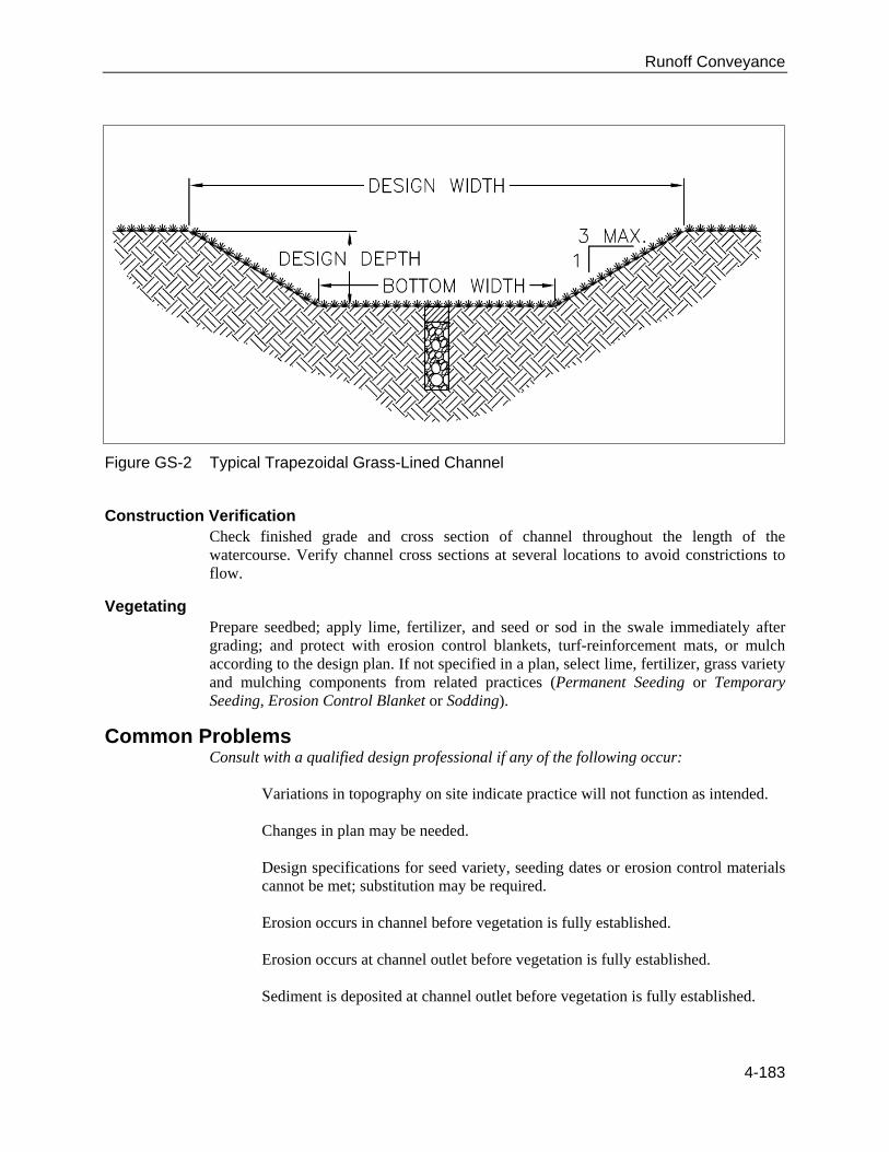
Constructing Excavate and shape the channel to dimensions shown in the design specifications, removing and properly disposing of excess soil so surface water can enter the channel freely. The typical features of a grass swale are shown in Figure GS-2 and listed below, but may be different in the design for a specific site.
Cross Section: trapezoidal or parabolic. Side Slopes: 3:1 (Horizontal: Vertical) or flatter for trapezoidal channels. Outlet: Channel should empty into a stable outlet, sediment traps, or detention/retention basins. Subsurface Drain: Use in areas with seasonally high water tables or seepage problems. Topsoil: Provide topsoil as needed to grow grass on areas disturbed by construction.
Protect all concentrated inflow points along the channel with erosion-resistant linings, such as riprap, sod, mulch, erosion control blankets, turf-reinforcement mats or other appropriate practices as specified in the design plan.
Runoff Conveyance
4-183
Figure GS-2 Typical Trapezoidal Grass-Lined Channel
Construction Verification Check finished grade and cross section of channel throughout the length of the watercourse. Verify channel cross sections at several locations to avoid constrictions to flow.
Vegetating Prepare seedbed; apply lime, fertilizer, and seed or sod in the swale immediately after grading; and protect with erosion control blankets, turf-reinforcement mats, or mulch according to the design plan. If not specified in a plan, select lime, fertilizer, grass variety and mulching components from related practices (Permanent Seeding or Temporary Seeding, Erosion Control Blanket or Sodding).
Common Problems Consult with a qualified design professional if any of the following occur:
Variations in topography on site indicate practice will not function as intended. Changes in plan may be needed. Design specifications for seed variety, seeding dates or erosion control materials cannot be met; substitution may be required. Erosion occurs in channel before vegetation is fully established. Erosion occurs at channel outlet before vegetation is fully established. Sediment is deposited at channel outlet before vegetation is fully established.

Runoff Conveyance
4-184
Maintenance Inspect the channel following storm events both during and after grass cover is established; make needed repairs immediately. Check the channel outlet and road crossings for blockage, ponding, sediment, and bank instability, breaks and eroded areas; remove any blockage; and make repairs immediately to maintain design cross section and grade.
References
BMPs from Volume 1 Chapter 4 Erosion Control Blanket (ECB) 4-33 Permanent Seeding (PS) 4-53 Sodding (SOD) 4-93 Temporary Seeding (TS) 4-103 Lined Swale (LS) 4-190 Riprap-lined Swale (RS) 4-210
MDOT Drawing DT-1 Details of Typical Ditch Treatments 4-185

Runoff Conveyance
4-185

Runoff Conveyance
4-186
Level Spreader (LVS)
Practice Description A level spreader provides a non-erosive outlet for concentrated runoff (diversions) by dispersing flow uniformly across a stable slope. They are relatively low-cost structures designed to release small volumes of water safely.
Planning Considerations Level spreaders are designed to be used where sediment-free storm runoff is intercepted and diverted away from graded areas onto undisturbed stabilized areas. This practice applies only in those situations where the spreader can be constructed on undisturbed soil and the area below the level crest is stabilized by natural or pre-established vegetation. The water should not be allowed to re-concentrate after release. The drainage area for a level spreader should be limited to 5 acres, and the size of the spreader based on design runoff. When the level spreader is used as an outlet for temporary or permanent diversions, runoff containing high sediment loads must be treated in a sediment trapping device before release into a level spreader (see Sediment Basin Practice).
Design Criteria Capacity
The capacity of the spreader crest shall be limited to those drainage areas producing no more than 40 cfs from a 10-year storm.
Length By estimating the flow, the spreader crest length can be determined from the following table.

Runoff Conveyance
4-187
Design Flow (CFS) Minimum Depression Depth
(Feet) Minimum Length (Feet)
0-10 0.5 10 10-20 0.6 20 20-30 0.7 30 30-40 0.8 40
Width
The minimum acceptable width of the depressional area along the level crest shall be 6 feet.
Grade The grade of the channel for the last 20 feet of the dike or diversion entering the level spreader shall be less than or equal to 1%. The grade of the depression along the level spreader shall be 0%.
Outlet The release of the stormwater will be over the level crest onto an undisturbed stabilized area. The level crest should be of uniform height and zero grade over the length of the spreader crest.
Setback Level spreader setbacks should be a minimum of 10 feet from property lines and receiving water features. Sheet flow depth at property lines shall be consistent with pre-development flow.
Construction
Site Preparation
Level spreaders must be constructed on undisturbed soil (not fill material).
Figure LVS-1 Level Spreader, Sectional View (Source: NRCS)

Runoff Conveyance
4-188
Level Spreader Crest The level spreader crest shall be constructed to a uniform height and zero grade over the length of the spreader. For flows of 4 cfs or greater, a rigid crest of non-erodible material shall be used. For flows less than 4 cfs, a vegetated crest may be used. An erosion control blanket should be used with a vegetative crest (see Erosion Control Blanket Practice for blanket requirements). The erosion control blanket should be a minimum of 4 feet wide and extend at least 1 foot downstream. Secure the blanket with heavy duty staples and bury the upstream and downstream edges in a trench at least 6 inches deep.
Erosion control blankets should be used for rigid crest level spreaders as well. The erosion control blanket should be entrenched a minimum of 4 inches below existing ground and securely anchored to prevent displacement. An apron of coarse aggregate should be placed along the rigid crest and extended downslope at least 3 feet.
Vegetation The natural buffer-area vegetation is important to improve infiltration function, protect from rain and wind erosion and enhance aesthetic conditions. The level spreader itself does not need vegetation. The lower buffer area should be protected from disturbance during construction.
Filter Strip Level spreaders used in conjunction with a filter strip should have a capacity designed based on the filter strip specifics (See Filter Strip Practice). The spreader shall run linearly along the entire width of the filter strip to which is discharges. The ends of the spreader should be tied into higher ground to prevent flow around the spreader.
Common Problems Consult with a qualified design professional if any of the following occur:
Variations in topography on site indicate practice will not function as intended; changes in plan may be needed. Design specifications cannot be met; substitution may be required. Unapproved substitutions could result in failure of the practice.
Maintenance Annual inspection is required. Trees and shrubs that have established on the level spreader crest should be removed. Inspection should occur annually for the presence of debris and sediment buildup on the level spreader. Regulation inspection, especially after significant rain events (greater than 3-4 inches in 24-hours), should be done to address possible erosion and gully formation.

Runoff Conveyance
4-189
References BMPs from Volume 1 Chapter 4 Erosion Control Blanket (ECB) 4-33 Permanent Seeding (PS) 4-53 Temporary Seeding (TS) 4-103 Diversion (DV) 4-131 Outlet Protection (OP) 4-199 Sediment Basin (SBN) 4-298

Runoff Conveyance
4-190
Lined Swale (LS)
Practice Description A lined swale is a constructed channel with a permanent lining designed to carry concentrated runoff to a stable outlet. This practice applies to the following sites: 1) where grass swales are unsuitable because of conditions such as steep channel grades, prolonged flow areas, soils that are too erodible or not suitable to support vegetation or insufficient space and/or 2) where riprap-lined swales are not desired. The purpose of a lined swale is to conduct stormwater runoff without causing erosion problems in the area of channel flow. The material that provides the permanent lining may be concrete, a specialized type of erosion control blanket, or manufactured concrete products.
Planning Considerations A lined swale is used to convey concentrated runoff to a stable outlet in situations where a grass swale is inadequate. A lined swale can be lined with concrete, manufactured concrete products, or manufactured erosion-control products. Concrete-lined swales are the only type of lining covered in this practice. The practice Erosion Control Blanket should be referenced for criteria on permanent erosion control blankets. Product manufacturers and qualified design professional should be consulted for design requirements for manufactured concrete linings. Concrete-lined swales are generally used in areas where riprap-lined swales are not desired due to aesthetics, safety, or maintenance concerns. Concrete-lined swales allow easy maintenance of surrounding vegetation with normal lawn care equipment. The concrete generally provides a more

Runoff Conveyance
4-191
visually pleasing structure than the riprap linings. Concrete-lined swales are especially desirable in areas accessed by small children. In areas where stormwater infiltration is a concern, riprap and manufactured products should be considered rather than the concrete lining.
Design Criteria
Capacity Lined swales should be capable of passing the peak flow expected from a 10-year 24-hour duration storm. Adjustments should be made for release rates from structures and other drainage facilities. Swales shall also be designed to comply with local stormwater ordinances, and should be designed for greater capacity whenever there is danger of flooding or when out-of-bank flow cannot be tolerated. Peak rates of runoff values used to determine the capacity requirements should be calculated using accepted engineering methods. Some accepted methods are:
Natural Resources Conservation Service, Engineering Field Manual for
Conservation Practices, Chapter 2, Estimating Runoff.
Natural Resources Conservation Service (formerly Soil Conservation Service), Technical Release 55, Urban Hydrology for Small Watersheds.
Other comparable methods – See Appendix A: Erosion and Stormwater Runoff Calculations found in the Appendices Volume.
Slope This practice applies only to paved flumes that are installed on slopes of 25% or less. Slopes steeper than this should be designed by a qualified design professional. The slope in feet per 100 feet of length can be determined from a topographic map of the site or from a detailed survey of the planned lined swale location.
Cross Section With peak flow (capacity) and slope known, the paved flume cross section can be determined by using Figures LS-l – LS-3.
Concrete Flumes should be constructed of concrete with a minimum 28-day compressive strength of 3,000 psi. Flumes shall have a minimum concrete thickness of 4″.

Runoff Conveyance
4-192
Cutoff Walls Cutoff walls shall be constructed at the beginning and end of every flume except where the flume connects with a catch basin or inlet.
Alignment Keep paved flumes as straight as possible because they often carry supercritical flow velocities.
Inlet Section The inlet section to the paved flume should be at least 6 feet long and have a bottom width equal to twice the bottom width of the flume itself. The bottom width should transition from twice the flume bottom width to the flume bottom width over the 6-foot length.
Outlet Outlets of paved flumes shall be protected from erosion. The standard for Outlet Protection can be used to provide this protection. A method to dissipate the energy of low flows is to bury the last section of the flume in the ground. This will usually force the development of a “scour hole,” which will stabilize and serve as a plunge basin. For the design of large-capacity flumes, it may be necessary to design a larger energy dissipater at the outlet.

Runoff Conveyance
4-193
Figure LS-1 Capacity Graph for Concrete Flumes Depth of Flow = 0.50 Foot

Runoff Conveyance
4-194
Figure LS-2 Capacity Graph for Concrete Flumes Depth of Flow = 0.75 Foot

Runoff Conveyance
4-195
Figure LS-3 Capacity Graph for Concrete Flumes Depth of Flow = 1.00 Foot

Runoff Conveyance
4-196
Construction Prior to start of construction, lined swales should be designed by a qualified design professional, and specifications should be available to field personnel. Plans and specifications should be referred to by field personnel throughout the construction process.
Note: Concrete-lined channel is the only lining method that is covered in this edition of the manual. Numerous permanent erosion control blankets and rock products are available with similar applications, and their unique installation procedures should be obtained from the manufacturer of the product being used. In addition, Riprap-Lined Swale is covered in this manual.
Site Preparation Determine exact location of underground utilities (See Appendix C: MS One-Call and 811 Color Coding). Remove brush, trees, and other debris from the channel and spoil areas, and dispose of properly. Grade or excavate cross section to the lines and grades shown in design for the concrete subgrade. Remove soft sections and unsuitable material and replace with suitable material. The subgrade should be thoroughly compacted and shaped to a smooth, uniform surface.
Material Placement Place forms to meet the specific plan design for the project, and place concrete of the designed mix into the forms according to construction specifications. Construction and expansion joints should be used where swale length exceeds 10 feet. Construction joints should be spaced at 10-foot intervals and expansion points at intervals not to exceed 20 feet. The subgrade should be moist at the time the concrete is placed. Place concrete for the lined channel to the thickness shown on the plans and finish it in a workmanlike manner. Coat the concrete with an approved curing compound as soon as finish work is complete and the free water has disappeared from the surface. Provisions should be made to protect the freshly poured concrete from extreme temperatures to ensure proper curing.
Stabilization Stabilize channel inlet and outlet points according to the design plan.

Runoff Conveyance
4-197
Stabilize adjacent disturbed areas after construction is completed with a vegetation treatment (see Permanent Seeding or Temporary Seeding Practices) and mulching. Provide topsoil, lime, and fertilizer as needed to grow grass on areas disturbed by construction. Many design plans specify a row of sod at the edges of the concrete channel. If not specified in a plan, select lime, fertilizer, variety and mulching components from related practices – Permanent Seeding or Temporary Seeding, Mulching, Erosion Control Blankets, or Sodding.
Construction Verification Check finished grades and cross sections throughout the length of the channel. Verify channel cross-section dimensions at several locations to avoid flow constrictions.
Common Problems Consult with a qualified design professional if any of the following occur:
Variations in topography on site indicate practice will not function as intended; changes in plan may be needed. Design specifications cannot be met; substitution may be required. Unapproved substitutions could result in failure of the practice.
Maintenance Inspect lined channel at regular intervals and after storm events. Check for erosion adjacent to the channel, at inlets and outlets, and underneath the lined channel. Give special attention to the channel inlet and outlet, and repair eroded areas promptly. Inspect for erosion in the entire swale, and repair with appropriate vegetative treatment (permanent or temporary seeding and mulching).
References
BMPs from Volume 1 Chapter 4 Erosion Control Blanket (ECB) 4-33 Permanent Seeding (PS) 4-53 Sodding (SOD) 4-93 Temporary Seeding (TS) 4-103 Outlet Protection (OP) 4-199
MDOT Drawing DT-1 Details of Typical Ditch Treatments 4-198

Runoff Conveyance
4-198

Runoff Conveyance
4-199
Outlet Protection (OP)
Practice Description This practice is designed to prevent erosion at the outlet of a channel or conduit by reducing the velocity of flow and dissipating the energy. Outlet protection measures usually consist of a riprap-lined apron, a reinforced concrete flume with concrete baffles, a reinforced concrete box with chambers or baffles, and possibly pre-manufactured products. This practice applies wherever high-velocity discharge must be released on erodible material.
Planning Considerations The outlets of pipes and structurally lined channels are points of critical erosion potential. Stormwater that is transported through man-made conveyance systems at design capacity generally reaches a velocity that exceeds the ability of the receiving channel or area to resist erosion. To prevent scour at stormwater outlets, a flow transition structure is required, which will absorb the initial impact of the flow and reduce the flow velocity to a level that will not erode the receiving channel or area of discharge. The most commonly used structure for outlet protection is an erosion-resistant lined apron. These aprons are generally lined with loose rock riprap, grouted riprap, or concrete. They are constructed at zero grade for a distance that is related to the outlet flow rate and the tailwater level. Criteria for designing these structures are contained in this practice. Several outlet conditions are shown in Figure OP-1. Example design problems for outlet protection are found at the end of this practice.
Runoff Conveyance
4-200
Where the flow is excessive for the economical use of an apron, excavated stilling basins may be used. Acceptable designs for stilling basins may be found in the following documents available from the U.S. Government Printing Office.
1) Hydraulic Design of Energy Dissipaters for Culverts and Channels, Hydraulics
Engineering Circular No.14, U.S. Department of Transportation, Federal Highway Administration.
2) Hydraulic Design of Stilling Basins and Energy Dissipaters, Engineering Monograph No. 25, U.S. Department of Interior-Bureau of Reclamation.
Design Criteria and Construction Structurally lined aprons at the outlets of pipes and paved channel sections should be designed according to the following criteria:
Pipe Outlets
Capacity The structurally lined apron should have the capacity to carry the peak stormflow from the 25-year 24-hour frequency storm, or the storm specified in state laws or local ordinances, or the design discharge of the water conveyance structure, whichever is greatest.
Tailwater The depth of tailwater immediately below the pipe outlet must be determined for the design capacity of the pipe. Manning’s Equation may be used to determine tailwater depth. Manning’s Equation may be found in Appendix A: Erosion and Stormwater Runoff Calculations (available in the Appendices Volume). If the tailwater depth is less than half the diameter of the outlet pipe, it shall be classified as a Minimum Tailwater Condition. If the tailwater depth is greater than half the pipe diameter, it shall be classified as a Maximum Tailwater Condition. Pipes that outlet to flat areas, with no defined channel, may be assumed to have a Minimum Tailwater Condition.
Apron Length The apron length should be determined from Figure OP-2 or OP-3 according to the tailwater condition.
Apron Thickness The apron thickness should be determined by the maximum stone size (dmax), when the apron is lined with riprap. The maximum stone size shall be 1.5 × d50 (median stone size), as determined from Figure OP-2 or OP-3. The apron thickness shall be 1.5 × dmax. When the apron is lined with concrete, the minimum thickness of the concrete shall be 4″.

Runoff Conveyance
4-201
Figure OP-1 Pipe Outlet Conditions

Runoff Conveyance
4-202
Figure OP-2 Outlet Protection Design for Tailwater <0.5 Diameter
Apron Width If the pipe discharges directly into a well-defined channel, the apron should extend across the channel bottom and up the channel banks to an elevation 1 foot above the maximum tailwater depth or to the top of the bank, whichever is the least. If the pipe discharges onto a flat area with no defined channel, the width of the apron should be determined as follows:
The upstream end of the apron, adjacent to the pipe, should have a width 3 times
the diameter of the outlet pipe. For a Minimum Tailwater Condition, the downstream end of the apron should
have a width equal to the pipe diameter plus the length of the apron obtained from the figures.
For a Maximum Tailwater Condition, the downstream end shall have a width
equal to the pipe diameter plus 0.4 times the length of the apron from Figure OP-2 or OP-3.

Runoff Conveyance
4-203
Bottom Grade The apron should be constructed with no slope along its length (0.0% grade). The invert elevation of the downstream end of the apron shall be equal to the elevation of the invert of the receiving channel. There shall be no overfall at the end of the apron.
Side Slope If the pipe discharges into a well-defined channel, the side slopes of the channel should not be steeper than 2:1 (Horizontal: Vertical).
Alignment The apron should be located so that there are no bends in the horizontal alignment.
Figure OP-3 Outlet Protection Design for Tailwater ≥0.5 Diameter
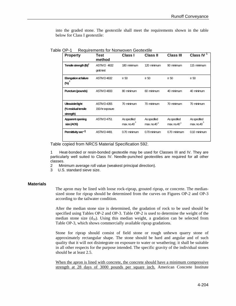
Geotextile When riprap is used to line the apron, geotextile should be used as a separator between the graded stone, the soil subgrade, and the abutments. Geotextile should be placed immediately adjacent to the subgrade without any voids between the fabric and the subgrade. The geotextile will prevent the migration of soil particles from the subgrade
Runoff Conveyance
4-204
into the graded stone. The geotextile shall meet the requirements shown in the table below for Class I geotextile:
Table OP-1 Requirements for Nonwoven Geotextile Property Test
method Class I Class II Class III Class IV 1
Tensile strength (lb)2 ASTM D 4632
grab test
180 minimum 120 minimum 90 minimum 115 minimum
Elongation at failure
(%) 2
ASTM D 4632 ≥ 50 ≥ 50 ≥ 50 ≥ 50
Puncture (pounds) ASTM D 4833 80 minimum 60 minimum 40 minimum 40 minimum
Ultraviolet light
(% residual tensile
strength)
ASTM D 4355
150-hr exposure
70 minimum 70 minimum 70 minimum 70 minimum
Apparent opening
size (AOS)
ASTM D 4751 As specified
max. no.40 3
As specified
max. no.40 3 As specified
max. no.40 3 As specified
max. no.40 3
Permittivity sec–1 ASTM D 4491 0.70 minimum 0.70 minimum 0.70 minimum 0.10 minimum
Table copied from NRCS Material Specification 592.
1 Heat-bonded or resin-bonded geotextile may be used for Classes III and IV. They are particularly well suited to Class IV. Needle-punched geotextiles are required for all other classes. 2 Minimum average roll value (weakest principal direction). 3 U.S. standard sieve size.
Materials The apron may be lined with loose rock-riprap, grouted riprap, or concrete. The median-sized stone for riprap should be determined from the curves on Figures OP-2 and OP-3 according to the tailwater condition. After the median stone size is determined, the gradation of rock to be used should be specified using Tables OP-2 and OP-3. Table OP-2 is used to determine the weight of the median stone size (d50). Using this median weight, a gradation can be selected from Table OP-3, which shows commercially available riprap gradations. Stone for riprap should consist of field stone or rough unhewn quarry stone of approximately rectangular shape. The stone should be hard and angular and of such quality that it will not disintegrate on exposure to water or weathering; it shall be suitable in all other respects for the purpose intended. The specific gravity of the individual stones should be at least 2.5. When the apron is lined with concrete, the concrete should have a minimum compressive strength at 28 days of 3000 pounds per square inch. American Concrete Institute

Runoff Conveyance
4-205
guidelines should be used to design concrete structures and reinforcement. As a minimum, the concrete should be reinforced with steel-welded wire fabric.
Construction Prior to start of construction, the practice should be designed by a qualified design professional. Plans and specifications should be referred to by field personnel throughout the construction process. The structure should conform to the dimensions, grades and alignments shown on the plans and specifications.
Site Preparation Completely remove stumps, roots, and other debris from the construction area. Fill depressions caused by clearing and grubbing operations with clean, non-organic soil. Grade the site to the lines and grades shown on the plans. Compact any fill required in the subgrade to the density of the surrounding undisturbed material. If possible, the alignment should be straight throughout its length. If a curve is required, it should be located in the upstream section of the outlet.
Riprap Structures Ensure that the subgrade for the filter and riprap follows the required lines and grades shown in the plan. Low areas in the subgrade on undisturbed soil may also be filled by increasing the riprap thickness. Geotextile fabric must meet design requirements and be properly protected from puncturing or tearing during installation. Repair any damage by removing the riprap and placing another piece of filter cloth over the damaged area. All connecting joints should overlap a minimum of 1.5 feet with the upstream edge over the downstream edge. If the damage is extensive, replace the entire geotextile fabric. Riprap may be placed by equipment; however, care should be taken to avoid damaging the filter.
Construct the apron on zero grade with no overfall at the end. Make the top of the riprap at the downstream end level with the receiving area or slightly below it.
Concrete Structures Reinforcing steel-welded wire fabric should be placed in strict accordance with the design plans and maintained in the proper position during the pouring of concrete. Concrete should be placed in horizontal layers not exceeding 24″ in thickness, or as specified in the design, and consolidated by mechanical vibrating equipment supplemented by hand-spading, rodding, or tamping. Concrete should be placed in sturdy wood or metal forms, adequately supported to prevent deformation. Forms should be oiled prior to placement to prevent bonding between concrete and forms. If possible, concrete should not be placed during inclement weather or periods of temperature extremes. If temperature extremes cannot be avoided, American Concrete Institute guidelines for placement of concrete during such extremes should be consulted.

Runoff Conveyance
4-206
Concrete should be allowed to cure as required by the plans and specifications. Typically, the surface should be kept wet during curing by covering it with wet burlap sacks or other means. Design strengths should be confirmed by laboratory tests on representative cylinders made during concrete placement. Form work should not be removed prior to the specified time.
Table OP-2 Size of Riprap Stones Rectangular Shape
Weight Mean Spherical Diameter (feet)
Length Width, Height (feet)
50 0.8 1.4 0.5
100 1.1 1.75 0.6
150 1.3 2.0 0.67
300 1.6 2.6 0.9
500 1.9 3.0 1.0
1000 2.2 3.7 1.25
1500 2.6 4.7 1.5
2000 2.75 5.4 1.8
4000 3.6 6.0 2.0
6000 4.0 6.9 2.3
8000 4.5 7.6 2.5
20000 6.1 10.0 3.3
Table OP-3 Graded Riprap
Class Weight (lbs.)
d10 d15 d25 d50 d75 d90 1 10 - - 50 - 100
2 10 - - 80 - 200
3 - 25 - 200 - 500
4 - - 50 500 1000 -
5 - - 200 1000 - 2000

Runoff Conveyance
4-207
Figure OP-4 Paved Channel Outlet
1) The flow velocity at the outlet of paved channels flowing at design capacity should not exceed the velocity, which will cause erosion and instability in the receiving channel.
2) The end of the paved channel should merge smoothly with the receiving channel section. There should be no overfall at the end of the paved section. Where the bottom width of the paved channel is narrower than the bottom width of the receiving channel, a transition section should be provided. The maximum side divergence of the transition shall be 1 in 3F where F = v/gd, and F = Froude no. v = Velocity at beginning of transition (ft/sec.) d = Depth of flow at beginning of transition (feet.) g = 32.2 ft/sec.2
3) Bends or curves in the horizontal alignment of the transition are not allowed unless the Froude no. (F) is 0.8 or less, or the section is specifically designed for turbulent flow.

Runoff Conveyance
4-208
Example Design Problems
Example 1
Given: An 18″ pipe discharges 24 cu. ft/sec at design capacity onto a grassy slope (no defined channel).
Find: The required length, width and median stone size (d50) for a riprap-lined apron.
Solution Since the pipe discharges onto a grassy slope with no defined channel, a Minimum Tailwater Condition may be assumed. From Figure OP-2, an apron length (La) of 20 feet and a median stone size (d50) of 0.8 foot is determined. The upstream apron width equals 3 times the pipe diameter: 3 × 1.5 feet = 4.5 feet. The downstream apron width equals the apron length plus the pipe diameter: 20 feet + 1.5 foot = 21.5 feet.
Example 2
Given: The pipe in example No. 1 discharges into a channel with a triangular cross section, 2 feet deep and 2:1 side slopes. The channel has a 2% slope and an “n” coefficient of 0.045.
Find: The required length, width and the median stone size (d50) for a riprap lining.
Solution Determine the tailwater depth using Manning’s Equation and the Continuity Equation.
Q = 1.49/n R 2/3 S 1/2 A 24 = 1.49/n [2d/4.47]2/3 (0.02)1/2 (2d2)
where, d = depth of tailwater d = 1.74 feet * *Since d is greater than half the pipe diameter, a Maximum Tailwater Condition exists.

Runoff Conveyance
4-209
From Figure OP-3, a median stone size (d50) of 0.5 foot and an apron length (La) of 41 feet is determined. The entire channel cross section should be lined, since the maximum tailwater depth is within 1 foot of the top of the channel.
Construction Verification
Check finished structures for conformance with design specifications.
Common Problems Consult with a qualified design professional if any of the following occur:
Variations in topography on site indicate measure will not function as intended. Design specifications for riprap, filter fabric, concrete, reinforcing steel, or backfill cannot be met; substitutions may be required. Unapproved substitutions could lead to failure. Problems with the structure develop during or after installation.
Maintenance Inspect riprap outlet structures after heavy rains to see if any erosion around or below the riprap has taken place or if stones have been dislodged. Check concrete structures for cracks and movement. Immediately make all needed repairs to prevent further damage.
References
BMPs from Volume 1 Chapter 4 Grass Swale (GS) 4-162

Runoff Conveyance
4-210
Riprap-lined Swale (RS)
Practice Description A riprap-lined swale is a natural or constructed channel with an erosion-resistant rock lining designed to carry concentrated runoff to a stable outlet. This practice applies where grass swales are unsuitable because of conditions such as steep channel grades, prolonged flow areas, or soils that are too erodible or not suitable to support vegetation or insufficient space.
Planning Considerations Swales should be carefully built to the design cross section, shape, and dimensions. Swales are hydraulic structures and as such depend upon the hydraulic parameters to serve satisfactorily. Swales may be used to
Serve as outlets for diversions and sediment control basins and stormwater
detention basins.
Convey water collected by road ditches or discharged through culverts.
Rehabilitate natural draws and gullies carrying concentrations of runoff.
The design of a swale cross section and lining is based primarily upon the volume and velocity of flow expected in the swale. Riprap-lined swales should be used where velocities are in the range of 5 to 10 ft/sec.

Runoff Conveyance
4-211
Besides the primary design considerations of capacity and velocity, a number of other important factors should be taken into account when selecting a cross section. These factors include land availability, compatibility with land use and surrounding environment, safety, maintenance requirements, and outlet conditions, etc.
Riprap-lined swales are trapezoidal in shape. Trapezoidal swales are often used where the quantity of water to be carried is large and conditions require that it be carried at a relatively high velocity. Outlet conditions for all swales should be considered. This is particularly important for the transition from the riprap lining to a vegetative lining. Appropriate measures must be taken to dissipate the energy of the flow to prevent scour of the receiving swale.
Design Criteria
Capacity Lined swales shall be designed to convey the peak rate of runoff from a 10-year 24-hour rainfall event. Adjustments should be made for release rates from structures and other drainage facilities. Swales should also be designed to comply with local stormwater ordinances. Swales should be designed for greater capacity whenever there is danger of flooding or when out-of-bank flow cannot be tolerated. The maximum capacity of the swale flowing at design depth should be 200 cubic ft/sec. Peak rates of runoff values used to determine the capacity requirements should be calculated using accepted engineering methods. Some accepted methods are:
Natural Resources Conservation Service, National Engineering Handbook Series, Part 650, Engineering Field Handbook, Chapter 2, Estimating Runoff.
Natural Resources Conservation Service (formerly Soil Conservation Service), Technical Release 55, Urban Hydrology for Small Watersheds.
Other comparable methods – See Appendix A: Erosion and Stormwater Runoff Calculations found in the Appendices Volume.
Cross section The swale cross section should be trapezoidal in shape. The steepest permissible side slope of the swale should be 2:1 (Horizontal: Vertical). A bottom width should be selected based on area available for installation of the swale and available rock sizes. The bottom width will be used in determining stable rock size and flow depth.
Depth Design flow depth should be determined by the following formula:
z = [n(q )/1.486(S)0.50]3/5
S = Bed slope, (ft/ft) z = Flow depth, (ft) q = Unit discharge, (ft3/s/ft) (Total discharge Bottom width) n = Manning’s coefficient of roughness (see formula under velocities)

Runoff Conveyance
4-212
The design water surface elevation of a swale receiving water from other tributary sources should be equal to or less than the design water surface elevation of the contributing source. The design water surface elevation of contributing and receiving waters should be the same, whenever practical. A minimum depth may be necessary to provide adequate outlets for subsurface drains and tributary swales.
Freeboard The minimum freeboard is 0.25 foot. Freeboard is not required on swales with less than 1% slope and where out-of-bank flow will not be damaging and can be tolerated from an operational point of view.
Stable Rock Size Stable rock sizes, for rock-lined swales having gradients between 2 percent and 40 percent should be determined using the following formulas from Design of Rock Chutes by Robinson, Rice, and Kadavy.
For swale slopes between 2% and 10%: d50 = [q (S)1.5/4.75(10)-3]1/1.89
For swale slopes between 10% and 40%: d50 = [q (S)0.58/3.93(10)-2]1/1.89
d50 = Particle size for which 50 % of the sample is finer, inch S = Bed slope, ft/ft q = Unit discharge, ft3/s/ft (Total discharge Bottom width)
After the stable median stone size is determined, the gradation of rock to be used should be specified using Tables RS-1 and RS-2. Table RS-1 is used to determine the weight of the median stone size (d50). Using this median weight, a gradation can be selected from Table RS-2, which shows commercially available riprap gradations.
Table RS-1 Size of Riprap Stones
Weight (lbs) Mean Spherical Diameter (feet)
Rectangular Shape
Length Width, Height (feet)
50 0.8 1.4 0.5
100 1.1 1.75 0.6
150 1.3 2.0 0.67
300 1.6 2.6 0.9
500 1.9 3.0 1.0
1000 2.2 3.7 1.25
1500 2.6 4.7 1.5
2000 2.75 5.4 1.8
4000 3.6 6.0 2.0
6000 4.0 6.9 2.3
8000 4.5 7.6 2.5
20000 6.1 10.0 3.3

Runoff Conveyance
4-213
Table RS-2 Graded Riprap
Class Weight (lbs.)
d10 d15 d25 d50 d75 d90
1 10 - - 50 - 100
2 10 - - 80 - 200
3 - 25 - 200 - 500
4 - - 50 500 1000 -
5 - - 200 1000 - 2000
Velocities Velocities should be computed by using Manning’s Formula with a coefficient of roughness, “n,” as follows: n = 0.047(d50·S)0.147
Applies on slopes between 2 and 40% with a rock mantle thickness of 2 × d50 where: d50 = median rock diameter (inch), S = lined section slope (ft/ft) (0.02 ≤ S ≤ 0.4)
Velocities exceeding critical velocity should be restricted to straight reaches. Waterways or outlets with velocities exceeding critical velocity should discharge into an outlet protection structure to reduce discharge velocity to less than critical (see Outlet Protection Practice).
Lining Thickness The minimum lining thickness should be equal to the maximum stone size of the specified riprap gradation plus the thickness of any required filter or bedding.
Lining Durability Stone for riprap should consist of field stone or rough unhewn quarry stone of approximately rectangular shape. The stone should be hard and angular and of such quality that it will not disintegrate on exposure to water or weathering, and it should be suitable in all other respects for the purpose intended. The specific gravity of the individual stones should be at least 2.5.
Geotextiles Geotextiles should be used where appropriate as a separator between rock and soil to prevent migration of soil particles from the subgrade, through the lining material. Geotextiles should be Class I material as selected from Table RS-3.
Filters or Bedding Filters or bedding should be used where needed to prevent piping. Filters should be designed according to the requirements contained in the Subsurface Drain Practice. The minimum thickness of a filter or bedding should be 6″.

Runoff Conveyance
4-214
Table RS-3 Requirements for Nonwoven Geotextile Property Test
method Class I Class II Class III Class IV 1
Tensile strength (lb) 2 ASTM D 4632
grab test
180 minimum 120 minimum 90 minimum 115 minimum
Elongation at failure (%) 2 ASTM D 4632 ≥ 50 ≥ 50 ≥ 50 ≥ 50
Puncture (pounds) ASTM D 4833 80 minimum 60 minimum 40 minimum 40 minimum
Ultraviolet light
(% residual tensile
strength)
ASTM D 4355
150-hr exposure
70 minimum 70 minimum 70 minimum 70 minimum
Apparent opening size
(AOS)
ASTM D 4751 As specified
max. no. 40 3
As specified
max. no. 40 3
As specified
max. no. 40 3
As specified
max. no. 40 3
Permittivity sec–1 ASTM D 4491 0.70 minimum 0.70 minimum 0.70 minimum 0.10 minimum
Table copied from NRCS Material Specification 592.
1 Heat-bonded or resin-bonded geotextile may be used for Classes III and IV. They are particularly well suited to Class IV. Needle-punched geotextile are required for all other classes.
2 Minimum average roll value (weakest principal direction). 3 U.S. standard sieve size.
Construction Prior to start of construction, riprap-lined swales should be designed by a qualified design professional. Plans and specifications should be referred to by field personnel throughout the construction process.
Site Preparation Determine exact location of underground utilities (See Appendix C: MS One-Call and 811 Color Coding.) Remove brush, trees, and other debris from the channel and spoil areas, and dispose of properly. Grade or excavate cross section to the lines and grades shown in design. Over-excavate to allow for thickness of riprap and filter material. Foundation excavation not deep enough or wide enough may cause riprap to restrict channel flow and result in overflow and erosion. Side slopes are usually 2:1 (Horizontal: Vertical) or flatter.
Foundation Stabilization Install geotextile fabric or aggregate in the excavated channel as a foundation for the riprap. Anchor fabric in accordance with design specifications. If the fabric is omitted or damaged during stone placement, there may be settlement failure and bank instability.

Runoff Conveyance
4-215
Installation As soon as the foundation is prepared, place the riprap to the thickness, depth, and elevations shown in the design specifications. It should be a dense, uniform, and well-graded mass with few voids. Riprap should consist of a well-graded mixture of stone (size and gradation as shown in design specifications) that is hard, angular, and highly chemical, and weather resistant. Larger stone should predominate, with sufficient smaller sizes to fill the voids between the stones. The diameter of the largest stone size should be not greater than 1.5 times the d50 size. Minimum thickness of riprap liner should be 1.5 times the maximum stone diameter. Blend the finished rock surface with the surrounding land surface so there are no overfalls, channel constrictions, or obstructions to flow.
Outlet Stabilization Stabilize channel inlet and outlet points. Extend riprap as needed. Stabilize adjacent disturbed areas after construction is completed.
Construction Verification Check finished grades and cross sections throughout the length of the channel. Verify channel cross section dimensions at several locations to avoid flow constrictions.
Common Problems Consult with a qualified design professional if any of the following occur:
Variations in topography on site indicate channel will not function as intended; changes in plan may be needed.
Design specifications for riprap sizing, geotextile fabric or aggregate filter cannot be met; substitution may be required. Unapproved substitutions could result in channel erosion.
Maintenance Inspect channels at regular intervals and after storm events. Check for rock stability, sediment accumulation, piping, and scour holes throughout the length of the channel. Look for erosion at inlets and outlets. When stones have been displaced, remove any debris and replace the stones in such a way as to not restrict the flow of water. Give special attention to outlets and points where concentrated flow enters the channel and repair eroded areas promptly by extending the riprap as needed.

Runoff Conveyance
4-216
References BMPs from Volume 1 Chapter 4 Outlet Protection (OP) 4-199 Subsurface Drain (SD) 4-218
Additional Resources
Natural Resources Conservation Service, National Engineering Handbook Series, Part 650, Engineering Field Handbook, Chapter 2, Estimating Runoff.
Natural Resources Conservation Service (formerly Soil Conservation Service), Technical Release 55, Urban Hydrology for Small Watersheds.
Robinson, K.M., Rice, C.E., and Kadavy, K.C., 1998. Design of Rock Chutes. Am. Soc. Agric. Eng. Trans. 41, 621–626.
MDOT Drawing DT-1 Details of Typical Ditch Treatments 4-217

Runoff Conveyance
4-217

Runoff Conveyance
4-218
Subsurface Drain (SD)
Practice Description A subsurface drain is a perforated pipe or continuous layer of porous material installed below the ground surface that intercepts, collects, and carries excessive groundwater to a stable outlet. Subsurface drains by themselves do not provide erosion control. The purpose of a subsurface drain is to improve soil moisture conditions, vegetation growth, and ground stability. Subsurface drains may reduce wet ground from interfering with construction activities. Drains may be constructed using a gravel-filled trench, perforated pipe in gravel bedding, or manufactured drain panel products. This practice applies where groundwater is at or near the ground surface or where adequate drainage cannot be provided for surface runoff.
Planning Considerations To properly design and install this practice, a detailed site investigation will be required. This investigation should include a site survey to determine the location of the area to be drained, the depth of the area to be drained, the topography of the area to be drained, the outlet of the drain system, and the soils at the site. When considering use of this practice, the qualified design professional should consider the intended use of the area to be drained. Base flow and interflow of groundwater may increase with installation of this practice due to excess soil water being removed. Groundwater recharge may also be reduced by this practice. Finally, surface runoff may increase due to this practice reducing deep percolation at the site.

Runoff Conveyance
4-219
All federal, state, and local laws and regulations should be adhered to when planning and installing this practice.
Design Criteria
Layout and Depth In the absence of site-specific information, a depth of 3 feet and a spacing of 50 feet for drains should be adequate. However, it is recommended that site-specific information be obtained. Typical details of subsurface drain construction can be seen in Figures SD-1 and SD-2. The following guidelines should be followed. The depth at which the drain is installed will determine how much the water table is lowered. The minimum depth for the drain is 2 feet under normal conditions. The maximum depth is limited by the depth of the impermeable layer and, if a pipe is used in the drain, by the allowable load on the pipe used.
Spacing The permeability of the soil at the site and the depth of the drain will determine the spacing of the drain.
Multiple Drains In some cases more than one drain will be needed to achieve the desired results. The first drain should be installed, and additional drains should be added only if seepage or high water table problems continue.
Location Drains should be located a minimum of 50 feet from any trees to prevent damage to the trees.
Grade In areas where sedimentation is not likely, the minimum grades should be based on site conditions and a velocity of not less than 0.5 ft/sec. Where a potential for sedimentation exists, a velocity of not less than 1.4 ft/sec should be used to establish the minimum grades if site conditions permit. Otherwise, provisions should be made for prevention of sedimentation by filters or collection and for periodic removal of sediment from installed traps. Steep grades should be avoided.
Gravel Bedding Typically, 3″ or more of gravel is placed completely around the drain and graded to prevent the infiltration of fine-grained soils into the drain.
Filters and Filter Material Filters will be used around conduits, as needed, to prevent movement of the surrounding soil material into the conduit. The need for a filter will be determined by the characteristics of the surrounding soil material (i.e. permeability), site conditions, and the velocity of flow in the conduit. A suitable filter should be specified if
Local experience indicates a need.

Runoff Conveyance
4-220
Soil materials surrounding the conduit are dispersed clay, low-plasticity silts, or fine sands (ML or SM with plasticity index less than 7).
Where deep soil cracking is expected.
Where the method of installation may result in voids between the conduit and backfill material.
The filter can be geotextile filter fabric, sand, gravel, or sand-gravel combination. If a geotextile is used, it should meet the requirements of the material table found in the Outlet Protection Practice. Care should be taken when using geotextile filter fabric since small soil particles can clog the fabric. If a sand-gravel filter is specified, the filter gradation will be based on the gradation of the base material surrounding the conduit within the following limits:
D15 size smaller than 7 times d95 size, but not smaller than 0.6 mm. D15 size larger than 4 times d15 size. Less than 5% passing No. 200 sieve. Maximum size smaller than 1.5″.
D represents the filter material, and d represents the surrounding base material. The number following each letter is the percent of the sample, by weight, that is finer than that size. For example, D15 size means that 15 percent of the filter material is finer than that size. Specified filter material must completely encase the conduit so that all openings are covered with at least 3″ of filter material, except that the top of the conduit and side filter material may be covered by a sheet of plastic or similar impervious material to reduce the quantity of filter material required.
Clean-outs In long sections of drain and in areas where sedimentation is concerned, clean-outs should be installed in the drain to facilitate removal of sediment deposits.
Outlet and Protection The outlet must be protected against erosion and undermining of the conduit, entry of tree roots, damaging periods of submergence, and entry of rodents or other animals into the subsurface drain. A continuous section of rigid pipe without open joints or perforations will be used at the outlet end of the line and must discharge above the normal elevation of low flow in the outlet ditch. Corrugated plastic tubing is not suitable for the outlet section.
Materials Pipe should be perforated, continuous closed-joint pipes of corrugated plastic, concrete, corrugated metal, or bituminous fiber. The pipe should have sufficient strength to withstand the load to be placed on it under the planned installation design.

Runoff Conveyance
4-221
Manufacturer’s recommendations should be followed in designing the pipe to withstand design loads.
Figure SD-1 Details of Typical Subsurface Drain Construction
Figure SD-2 Details of Subsurface Drain Construction

Runoff Conveyance
4-222
Construction Prior to start of construction, subsurface drains should be designed by a qualified design professional. Materials such as sand, gravel, geotextile filter cloth, and pipe must be properly designed in order for the subsurface drain system to function properly. Plans and specifications should be available to field personnel.
Site Preparation Determine exact location of underground utilities. At least 3 days prior to construction, request Mississippi One-Call System (1-800-227-6477) to mark all underground utilities within the project area. See Appendix C for more information about utility marking. Locate and mark the alignment of the drains as shown on the design plans. Clear installation area of debris and obstacles, such as trees and stumps, that might hinder grading and installation of the subsurface drain.
Trench Excavation Excavate the trench to the specified depth and grade shown in the design plan. To accommodate the gravel bedding or filter material, excavate the trench to at least 3″ below the design bottom elevation of the pipe (or as shown on the design plans). Place materials excavated from the trench on the up-gradient side of the trench to prevent water from entering the trench during construction. Grade the trench to prevent siltation into the drain.
Installation of Drain Pipe, Bedding Material and Geotextile Filter Cloth Line trench with filter cloth (if specified), providing enough material to overlap over the top of the finished gravel bedding. This helps prevent movement of soil into the gravel. Spread bedding material specified in the design plan, usually 3″ of gravel, to fill the over-excavated bottom of the trench. Lay pipe on the design grade and elevation, avoiding reverse grade or low spots, after checking to ensure the pipe meets specifications. Cap the upper end of each drain with a standard cap made for this purpose or with concrete or other suitable material to prevent soil from entering the open end. Place bedding material around pipe, on all sides, with the amount shown in the design plan. Fold filter cloth over the top of the gravel bedding.
Backfill Installation Backfill immediately after placement of the pipe and bedding. Ensure that the material does not contain rocks or other sharp objects, and place it in the trench in a manner that will not damage or displace the pipe. Overfill the trench slightly to allow for settlement.

Runoff Conveyance
4-223
Installation of Clean-Out Device Install clean-outs for maintenance of the subsurface drain in the locations shown on design plan.
Outlet Installation Construct the outlet of the subsurface drain at the elevation in the design plan. The outlet section of the drain should be at least 10 feet of non-perforated corrugated metal, cast iron, steel, or heavy-duty plastic pipe. Cover at least half of the pipe length with well-compacted soil. Place a suitable animal guard securely over the pipe outlet to keep out rodents.
Stabilization Keep the settled fill over the pipe outlet slightly higher than the surrounding ground to prevent erosion, rills and gullies. Stabilize all bare areas of the trench with temporary seeding and mulching unless construction will disturb the area within 13 days.
Safety Narrow trenches are subject to collapse and can be a safety hazard to persons in the trench. No person should enter a trench without shoring protection or properly sloping the sides of the trench.
Construction Verification Verify the dimensions during construction with those shown on the plans for location, length, depth, and cross section of trench.
Verify the dimensions and specifications of the aggregate used in the bedding and manufactured materials such as pipe, tile or panel drain.
Common Problems Consult with a qualified design professional if any of the following occur:
Variations in topography on site indicate subsurface drains will not function as intended or originally designed. Design specifications for aggregate or manufactured products cannot be met; substitutions may be required. Unapproved substitutions could result in failure of the drain to function as intended. Pipe is crushed by construction traffic.
Maintenance Check subsurface drains periodically to ensure that they are free-flowing and not clogged with sediment. Keep outlet clean and free of debris. Keep surface inlets open and free of sediment and other debris.

Runoff Conveyance
4-224
Where drains are crossed by heavy vehicles, check the pipe to ensure that it is not crushed.
References
BMPs from Volume 1 Chapter 4 Outlet Protection (OP) 4-199

Runoff Conveyance
4-225
Temporary Slope Drain (TSD)
Practice Description A temporary slope drain is a pipe or other conduit designed to convey concentrated runoff down the face of a cut- or fill-slope without causing erosion. This practice applies wherever concentrated stormwater runoff must be conveyed down a steep slope.
Planning Considerations There is often a significant lag between the time a cut- or fill-slope is completed and the time a permanent runoff-conveyance system can be installed. During this period, the slope is usually not stabilized and is particularly vulnerable to erosion. This situation also occurs on slope construction that is temporarily delayed before final grade is reached. Temporary slope drains, sometimes called “downdrains,” can provide valuable protection of exposed slopes until permanent runoff-conveyance structures can be installed. See Figure TSD-1 for typical details of a temporary slope drain. When used in conjunction with diversions, temporary slope drains can be used to convey stormwater from the entire drainage area above a slope to the base of the slope without erosion. It is very important that these temporary structures be installed properly since their failure will often result in severe gully erosion. The entrance section must be securely entrenched, all connections must be watertight, and the conduit must be securely staked. Prior approval may be required from local regulatory agencies if the downdrain outlet is tied into an existing storm sewer or in areas where municipal stormwater is regulated.

Runoff Conveyance
4-226
Design Criteria
Drainage Area The maximum allowable drainage area per drain is 5 acres.
Flexible Conduit The downdrain should consist of heavy-duty flexible material designed for this purpose. The diameter of the downdrain should be equal over its entire length. Reinforced hold-down grommets should be spaced at 10-foot (or less) intervals, with the outlet end securely fastened in place. The conduit should extend beyond the toe of the slope. Downdrains may be sized according to the table TSD-1. Drains should be designed to convey the peak rate of runoff from a 10-year 24-hour rainfall whenever it is desired to individually design each installation.
Table TSD-1 Flexible Conduit Diameters
Maximum Drainage Area (Acres) Pipe Diameter (D) (Inches)
0.5 12
1.5 18
2.5 21
3.5 24
5.0 30
Entrance Sections The entrance to the downdrain (Figures TSD-2 and TSD-3) should consist of a standard flared end-section for metal pipe culverts. All fittings should be watertight. The toe plate should be a minimum of 8″ deep. Extension collars should consist of 12″ long corrugated metal pipe. Avoid use of helical pipe. Securing straps should be fabric, metal, or other material well suited to providing a watertight connection. The strap should secure at least one corrugation of the extension collar.
Diversion Design An earthen diversion should be used to direct stormwater runoff into the slope drain and should be constructed according to the Diversion Practice. The height of the diversion at the centerline of the inlet should be equal to at least the diameter of the pipe (D) plus 12″. Where the dike height is greater than 18″ at the inlet, it should be level for 3 feet each side of the pipe and be sloped at the rate of 3:1 (Horizontal: Vertical) or flatter to transition with the remainder of the dike.

Runoff Conveyance
4-227
Outlet Protection The outlet of the downdrain should be protected from erosion as detailed in the Outlet Protection Practice.
Figure TSD-1 Typical Temporary Slope Drain Detail

Runoff Conveyance
4-228
Figure TSD-2 Flared End-Section Detail
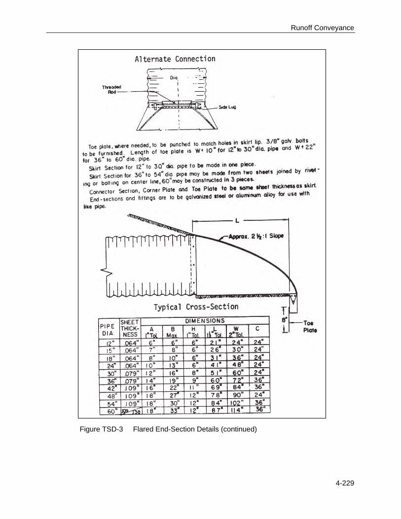
Runoff Conveyance
4-229
Figure TSD-3 Flared End-Section Details (continued)

Runoff Conveyance
4-230
Construction Prior to start of construction, temporary slope drains should be designed by a qualified design professional. Plans and specifications should be referred to by field personnel throughout the construction process.
Site Preparation Determine exact location of underground utilities (see Appendix C: MS One-Call and 811 Color Coding). Place temporary slope drain on undisturbed soil or well-compacted fill at locations and elevations shown on the plans. Grade the diversion channel at the top of the slope toward the temporary slope drain according to the design plan. Provide positive grade in the pipe under the ridge. Hand tamp the soil under and around the pipe in lifts not to exceed 6″. Ensure that the fill over the drain pipe at the top of the slope is placed to the dimensions shown on the design plan. Ensure that all slope drain connections are secure and watertight. Ensure that all fill material is well compacted. Securely anchor the exposed section of the drain according to the design. Extend the drain beyond the toe of the slope and adequately protect the outlet from erosion. Make the settled, compacted diversion ridge no less than 1 foot above the top of the pipe at every point.
Erosion Control Compaction of earthfill around the pipe in the vicinity of the ridge is extremely important to avoid piping failure and blowouts. Immediately stabilize all disturbed areas following construction according to the design plan (with vegetation or other appropriate means of protection).
Construction Verification Verify that materials, elevations, and installation procedures meet design specifications. Joints should be carefully inspected for separations or looseness.
Common Problems Consult with a qualified design professional if any of the following occur:
Variations in topography on site indicate temporary slope drains will not function as intended.

Runoff Conveyance
4-231
Pipe separates or is displaced. Animals are going into the pipe outlet.
Maintenance Inspect slope drains and supporting diversions once a week and after every storm event. Check the inlet for sediment or trash accumulation; clear and restore to proper condition. Check the fill over the pipe for settlement, cracking or piping holes; repair immediately. Check for holes where the pipe emerges from the ridge; repair immediately. Check the conduit for evidence of leaks or inadequate anchoring; repair immediately. Check the outlet for erosion or sedimentation; clean and repair, or extend if necessary. Once slopes have been stabilized, remove the temporary diversions and slope drains so that runoff water no longer concentrates but flows uniformly over the protected slope. Stabilize the diversion and slope drain areas.
References
BMPs from Volume 1 Chapter 4 Permanent Seeding (PS) 4-53 Temporary Seeding (TS) 4-103 Diversion (DV) 4-131 Outlet Protection (OP) 4-199
MDOT Drawing TEC-2 Typical Temporary Erosion Control Measures (Slope Drain and Type A Silt Basin)
4-232

Runoff Conveyance
4-232