RUMFORD 1000 Architectural Handbook - Comfort …€¦ · · 2016-03-11RUMFORD 1000 Architectural...
10
RUMFORD 1000 Architectural Handbook THIS BOOKLET IS NOT TO BE USED AS THE INSTALLATION MANUAL IT IS MERELY A GUIDE TO ASSIST WITH THE DESIGN PROCESS The Product Installation Manual can be downloaded in its entirety at www.renaissancefireplaces.com/en/installation-manuals
Transcript of RUMFORD 1000 Architectural Handbook - Comfort …€¦ · · 2016-03-11RUMFORD 1000 Architectural...

RUMFORD 1000
Architectural Handbook
THIS BOOKLET IS NOT TO BE USED AS THE INSTALLATION MANUAL
IT IS MERELY A GUIDE TO ASSIST WITH THE DESIGN PROCESS
The Product Installation Manual can be downloaded in its entirety at www.renaissancefireplaces.com/en/installation-manuals

TABLE O
F C
ON
TEN
TS
FOR REFERENCE ONLY! REFER TO MANUAL PRIOR TO INSTALLATION Page 2
Dear Customer,
This Booklet is designed to assist with planning for the installation of a
Renaissance Rumford Fireplace. It is NOT a replacement for the installation manual itself. Product installation manuals can be
downloaded at: http://www.renaissancefireplaces.com/en/installation-manuals
The Renaissance Rumford™ 1000 is the world’s first certified clean burning open fireplace. It combines technology with elegance, allowing
you to enjoy an open fire without compromising environmental quality.
We at Renaissance Fireplaces™ want to thank you for considering our fireplaces for your project.
Sincerely,
Renaissance FireplacesTM Team
April, 2010
TABLE OF CONTENTS
DIMENSIONS AND CLEARANCES 3
UNIT DIMENSIONS 3
CLEARANCES 4
PLANNING INSTALLATION 7
LOCATION 7
FINISHING 8
FRAMING 8
FIREPLACE FACING 8
HEARTH EXTENSION 8

DIM
EN
SIO
NS A
ND
CLEARAN
CES
FOR REFERENCE ONLY! REFER TO MANUAL PRIOR TO INSTALLATION
Page 3
DIMENSIONS AND CLEARANCES
UNIT DIMENSIONS
Figure 1 Fireplace Dimensions

DIM
EN
SIO
NS A
ND
CLEARAN
CES
FOR REFERENCE ONLY! REFER TO MANUAL PRIOR TO INSTALLATION Page 4
CLEARANCES
Figure 2 Fireplace Clearances

DIM
EN
SIO
NS A
ND
CLEARAN
CES
FOR REFERENCE ONLY! REFER TO MANUAL PRIOR TO INSTALLATION
Page 5
Table 1 Unit Clearances and Specifications
A Distance to combustible material from side, back and top
standoffs 0" (0.0 mm)
B Minimum distance from side wall to the side of the
fireplace opening 24" (610 mm)
C Minimum ceiling clearance: from the base of the fireplace
to the ceiling 8' (2.44 m)
D Minimum chimney height: minimum total chimney height
from fireplace top to below the chimney rain cap 12' (3.66 m)
E Maximum chimney height: maximum total chimney
height from fireplace top to below the chimney rain cap 60' (18.3 m)
F Maximum chimney height supported by the fireplace 15' (4.6 m)
G
Minimum depth of non-combustible hearth extension:
from the front of the fireplace (refer to the "Installation:
Hearth Extension" section for details)
24" (610 mm)
H
Minimum width of non-combustible hearth extension:
total width, must be centered on the firebox opening
(refer to the "Installation: Hearth Extension" section for
details)
45" (1.14 mm)
I Minimum width of the spark guard 45" (1.14 mm)
J Maximum mantel shelf depth (see Table 2 for other
mantel sizes) 12" (305 mm)
K
Minimum height of a combustible mantel shelf above the
top of the fireplace opening (to the bottom of the
combustible mantel) (refer to the "Installation: Mantel"
section for details)
See Table 2
L Maximum mantel post depth (see Table 3 for other
mantel post sizes) 12" (305 mm)
M
Minimum distance between each combustible mantel post
and the fireplace opening (refer to the "Installation:
Mantel" section for details)
See Table 3

DIM
EN
SIO
NS A
ND
CLEARAN
CES
FOR REFERENCE ONLY! REFER TO MANUAL PRIOR TO INSTALLATION Page 6
Table 2 Various Mantel Shelf Depths and Corresponding Installation Heights
Maximum Mantel Shelf
Depth
Minimum Installation
Height
0" to 6" 6"
12" 12"
No combustible mantel shelf can be installed lower than 6" above the top of the fireplace
opening. A combustible mantel shelf cannot be deeper than 12".
For combustible mantel shelf depths between 6" and 12", simply install the mantel shelf
at a distance above the fireplace opening corresponding to the mantel shelf depth:
• For example, mantel shelf depth to be installed: 9 ¼"
• It is between 6" and 12"
• Minimum installation height of a 9 ¼" mantel: 9 ¼" above the fireplace opening.
If the combustible mantel shelf has a cross-section with variable depth, it has to be
installed so that its widest part is not installed lower than the corresponding minimum
installation height while making sure that the lowest point of the mantel shelf is not
installed lower than the minimum installation height corresponding to its depth.
Refer to the "Installation: Mantel" section for particulars.
Table 3 Various Mantel Post Depths and Corresponding Installation Distance
Maximum Mantel Post
Depth
Minimum Installation
Distance
0" to 3" 6"
12" 10"
No combustible mantel post can be installed closer than 6" from either side of the
fireplace opening. A combustible mantel post cannot be deeper than 12".
For combustible mantel post depths between 6" and 12", you can calculate the minimum
installation distance between the two mantel posts given as follows:
• For example, mantel post depth to be installed: 9 ¼"
• It is between 3" and 12"
• So: (9.25 x 4/9) + 4.676 = 8.778 = 8 13/16"
• Minimum installation distance of a 9 ¼" mantel post: 8 13/16" from either side of
the fireplace opening.
If the combustible mantel post has a cross-section with variable depth, it has to be
installed so that its thickest part is not installed closer than the corresponding minimum
installation distance while making sure that the thinnest point of the mantel post is not
installed closer than the minimum installation distance corresponding to its depth.
Refer to the "Installation: Mantel" section for particulars.

PLAN
NIN
G I
NSTALLATIO
N
FOR REFERENCE ONLY! REFER TO MANUAL PRIOR TO INSTALLATION
Page 7
PLANNING INSTALLATION
Check with your local authority having jurisdiction (such as municipal building
department, fire department, fire prevention bureau, etc.) regarding restrictions and
installation requirements, and the need to obtain a permit.
LOCATION
Your RUMFORD 1000 fireplace may be installed in different ways (see Figure 3) without
any special floor reinforcement.
The framing dimensions are larger than required for ease of installation.
Figure 3 Framing Examples

FIN
ISH
ING
FOR REFERENCE ONLY! REFER TO MANUAL PRIOR TO INSTALLATION Page 8
FINISHING
FRAMING
The enclosure walls can be framed with any suitable materials (2"x4" or 2"x6" studs,
plywood, gypsum board, etc.). Because of the high heat output potential of the
RUMFORD 1000, combustible materials must NOT go closer to the fireplace than the
standoffs, top, back and sides.
FIREPLACE FACING
The RUMFORD 1000 has been provided with its own ½" cement board panels to cover
the front of the fireplace. The James Hardie HardieBacker® quality cement boards allow
you to finish the facing of the fireplace with any non-combustible material you like.
WARNING: DO NO REPLACE THESE CEMENT BOARD PANELS WITH GYPSUM
BOARDS.
COVERING THE FIREPLACE FACING
Facing materials must be NON-COMBUSTIBLE such as metal, brick, slate or ceramic tile.
Gypsum board is NOT an acceptable facing material. The only combustible material
accepted on the facing of the fireplace is for a mantel (shelf and posts).
The smooth surface of the HardieBacker® can be painted, textured or tiled just as you
would over gypsum boards. The lintels provided with the fireplace are appropriate for
thin facing materials. A wider steel lintel may be required for heavy rock. If so, contact
your local sheet metal contractor for a custom steel lintel.
If you need to attach anything to the front of the fireplace make sure to close the
guillotine door and firescreen before attempting to do so. Be sure to only penetrate by
no more than ¾" within 1" of the exterior edges. Any closer to the center will either
prevent the proper operation of the firescreen and/or the guillotine door, or eventually
causing difficulty dismantling the guillotine system.
CAUTION: IF ABSOLUTELY NECESSARY, YOU CAN SCREW INTO THE CEMENT
FACING ELSEWHERE AS LONG AS THE SCREW TIP DOES NOT COMPLETELY
PENETRATE THE ½" CEMENT BOARD PANELS.
Confirm that you have not impeded the normal operation of the firescreen and the
guillotine door by moving them slowly.
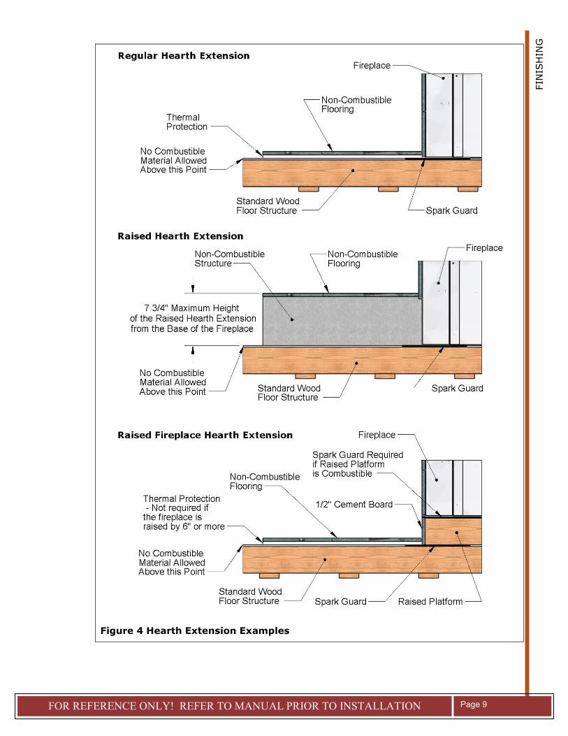
HEARTH EXTENSION
The area immediately in front of the fireplace must be protected. Refer to Table 1 (G-H)
for the depth and width that the hearth protection should extend beyond the front and
both sides of the fireplace opening (see Figure 2). Refer to Figure 4 for various
alternatives of hearth extension installation.
If the RUMFORD 1000 is installed on a non-combustible floor, NO requirements are
necessary.
FIN
ISH
ING
FOR REFERENCE ONLY! REFER TO MANUAL PRIOR TO INSTALLATION
Page 9
Figure 4 Hearth Extension Examples

RR1000 - 2010-04