2014-09-17 (9) 954 del 17...Title 2014-09-17 (9) Created Date 9/17/2014 2:36:09 PM
Upload
nguyenduongCategory
view
217download
1
RULES FORCERTIFICATION OF
FREIGHT CONTAINERS
NOVEMBER 1981
SECTIONS PAGE
1 General Requirements. . . . . . . . . . . . . . . . . . . . . . . . . . . . . . . . . . . . . . . . . 1
2 General Cargo Containers . . . . . . . . . . . . . . . . . . . . . . . . . . . . . . . . . . . . . 4
3 Thermal Containers . . . . . .. 10
4 Tank Containers . . . . . . . . . . . . . . . . . . . . . . . . . . . . . . . . . . . . . . . . . . . . . 15
5 Platforms and Platform-based Containers. . . . . . . . . . . . . . . . . . . . . . . . . 18
6 Repair of Containers after Damage . . . . . . . . . . . . . . . . . . . . . . . . . . . . . . 32
APPENDICES
1 Certificates.................................................. 34
2 Plate for CSC Safety Approval. . . . . . . . . . . . . . . . . . . . . . . . . . . . . . . . . . 39
3 Container Dimensions, Tolerances and Ratings. . . . . . . . . . . . . . . . . . . . . 40
4 Standard Corner Fittings '. . . . . 43
5 Load-transferring Areas in Base Structures of Containers. . . . . . . . . . . . 45
6 Optional Features . . . . . . . . . . . . . . . . . . . . . . . . . . . . . . . . . . . . . . . . . . . . 47
DETNORSKEVERITASVEIEN 1, 1322 H0VIK, NORWAYTELEPHONES: + 472 129900 TELEX: 76192

DECIDED BY THE BOARDAS OF NOVEMBER 1ST 1981
Printed in Norway by Det norske Veritas© Det norske Veritas
NV 11.81.2000

INTRODUCTION
General.
• These Rules were decided by the Board as of November 1st 1981 and supersede the Society's R u/es forthe Construction and Classification ofFreight Containers, 1977.
• The Rules have been completely rearranged for clarification and compliance with the principles nowapplied in the other Rule publications of the Society.
• The Rules are based on the following documents:
International Organization for Standardization (ISO)
International Standards:
ISO 1496/I-1978. 3rd editionSeries I. freight containers. Specification and Testing.Part I: General Cargo Containers.
ISO 1496/ II-1979. 2nd editionSeries I , freight containers. Specification and Testing.Part II: Thermal Containers.
ISO 1496/III-1974, lsteditionSeries I. freight containers. Specification and Testing.Tank containers for liquids and gases.
ISO I496/V-1977. 1st editionSeries I. freight containers. Specification and Testing.Part V: Platform (container).
ISO 1496/VIc-J977.lst editionSeries I. freight containers. Specification and Testing.Part YId: Platform-based containers. open-sided. with complete superstructure.
ISO 668-1979. 3rd editionSeries I , freight containers. Classification, external dimensions and ratings.
ISO 1161-19~O. 3rd editionSeries I. freight containers. Corner fittings. specification.
Draft International Standard:
ISO/DIS I 496/6aJ.3, December 1979Series I. freight containers. Specification and Testing.Part VIa>: Platform-based containers with incomplete superstructure and fixed ends.
Draft proposals:
ISO/OP 1496/I 1979Series I. freight containers. Specification and Testing.General purpose containers.
ISO/OP 1496/6b) 1981Series I. freight containers. Specification and Testing.Part VIb): Platform-based containers with incomplete superstructure and folding ends.
International Convention for Safe Containers (CSC). published by UN/IMCO 1974.
International Association of Classification Societies <rACS). Unified Requirements Nos. 88, 96. 97. 121and 122.
~ Oet norske Veritas cannot be responsible for keeping the holders of its Rules informed on any changesor additions in the above-mentioned documents nor in any other regulations affecting the containerconstruction or certification.
It Extracts from ISO-documents are printed with permission from Norges Standardiseringsforbund(Norwegian Standards Association>.
Major changes in the Rules.
~ Rule requirements for loadable platforms and platform-based containers of various configurations have been added.
() The Rule requirements for thermal containers and tank containers have been supplemented and updated.

CONTENTS
Page:
Sec. I General RequirementsA. Certification..................................................... IB. Documentation.................................................. 2C. Design approval. . . . . . . . . . . . . . . . . . . . . . . . . . . . . . . . . . . . . . . . . . . . . . . . . . 2D. Materials....................................................... 2E. Quality assurance system as basis for production survey ....' . . . . . . . . . . . . . 3
Sec. 2 General Cargo ContainersA. General requirements. . . . . . . . . . . . . . . . . . . . . . . . . . . . . . . . . . . . . . . . . . . . . 4B. Design requirements. . . . . . . . . . . . . . . . . . . . . . . . . . . . . . . . . . . . . . . . . . . . . . 4C. Testing......................................................... 5
Sec. 3 Thermal ContainersA. General requirements . . . . . . . . . . . . . . . . . . . . . . . . . . . . . . . . . . . . . . . . . . . . . 10B. General design and equipment. . . . . . . . . . . . . . . . . . . . . . . . . . . . . . . . . . . . . . 10C. Heating appliances. . . . . . . . . . . . . . . . . . . . . . . . . . . . . . . . . . . . . . . . . . . . . . . . I ID. Refrigerating appliances. . . . . . . . . . . . . . . . . . . . . . . . . . . . . . . . . . . . . . . . . . . 11E. Strength tests. . . . . . . . . . . . . . . . . . . . . . . . . . . . . . . . . . . . . . . . . . . . . . . . . . . . 12F. Weathertightness test. . . . . . . . . . . . . . . . . . . . . . . . . . . . . . . . . . . . . . . . . . . . . . I2G. Airtightness test. . . . . . . . . . . . . . . . . . . . . . . . . . . . . . . . . . . . . . . . . . . . . . . . . . 12H. Heat transfer test. . . . . . . . . . . . . . . . . . . . . . . . . . . . . . . . . . . . . . . . . . . . . . . . . 12I. Performance test of thermal appliances . . . . . . . . . . . . . . . . . . . . . . . . . . . . . . . 14J. Marking........................................................ 14
Sec. 4 Tank ContainersA. General requirements . . . . . . . . . . . . . . . . . . . . . . . . . . . . . . . . . . . . . . . . . . . . . I 5B. General design. . . . . . . . . . . . . . . . . . . . . . . . . . . . . . . . . . . . . . . . . . . . . . . . . . . 15C. Design of framework . . . . . . . . . . . . . . . . . . . . . . . . . . . . . . . . . . . . . . . . . . . . . I5D. Design of tank. . . . . . . . . . . . . . . . . . . . . . . . . . . . . . . . . . . . . . . . . . . . . . . . . . . 16E. Testing......................................................... 16F. Marking........................................................ 17
Sec. 5 Platforms and Platform-based ContainersA. General requirements. . . . . . . . . . . . . . . . . . . . . . . . . . . . . . . . . . . . . . . . . . . . . 18B. Design requirements. . . . . . . . . . . . . . . . . . . . . . . . . . . . . . . . . . . . . . . . . . . . . . 18C. Testing.......................................................... 19
Sec. 6 Repair of Containers after DamageA. General requirements. . . . . . . . . . . . . . . . . . . . . . . . . . . . . . . . . . . . . . . . . . . . . 32B. Approval of repair shops. . . . . . . . . . . . . . . . . . . . . . . . . . . . . . . . . . . . . . . . . . 32C. Approval of containers repaired in shops not approved for this purpose. . . . . 32
Appendix I Certificates.................................................... 34Appendix 2 Plate for CSC Safety Approval. . . . . . . . . . . . . . . . . . . . . . . . . . . . . . . . . . . . 39Appendix 3 External container dimensions, tolerances and ratings. . . . . . . . . . . . . . . . . . 40Appendix 4 Standard corner fittings : . . . 43Appendix 5 Load-transferring areas in base structures of containers. . . . . . . . . . . . . . . . 45Appendix 6 Optional features . . . . . . . . . . . . . . . . . . . . . . . . . . . . . . . . . . . . . . . . . . . . . . . 47

Sec. 1
SECTION 1GENERAL REQUIREMENTS
A 600A 700A 800
Contents.
A. Certification.A 100 Application.A 200 Scope.A 300 The certification concept.A 400 Certification of individually surveyed containers.A 500 Certification based on the manufacturer's quality
assurance system.Definitions.Marking.Nominal lengths of ISO-containers.
B. Documentation.B 100 Plans and calculations.B 200 Material certificates.
C. Design Approval.C 100 Individual approval.C 200 Type approval.
D. Materials.D 100 Metallic materials, general.D 200 Corner fitting materials.D 300 Non-metallic materials.
E. Quality Assurance System as Basis for ProductionSurvey.
E 100 General.
A. Certification.
A 100 Application.
101 These Rules apply to freight containers for repeateduse and which are:
suitable for intercontinental traffic.of closed or open box configuration.of tank configuration.of loadable platform or platform based configuration,designed to be easy to fill and empty,designed to facilitate the carriage of goods byone or more modes of transportation without intermediate reloading.fitted with devices permitting their easy handling, in particular during their transfer from one modeof transportation to another.
102 The term freight container includes neither vehiclesnor conventional packing.
103 The Rules apply to ISO standard containers, but relevant parts of the Rules may be applied also to non-ISOcontainers.
A 200 Scope.
201 The certification covers the freight container structure and any permanent equipment for filling, emptying,refrigerating. heating and safety purposes.
A 300 The certification concept.
30 I Freight containers designed. constructed. tested andmarked in compliance with the following Rules may becertified by Det norske Veritas. The certification of a container implies that a certificate is issued by the Society andthe Society's emblem on which the certificate number isstamped. is fixed to the container. This completes the Society's commission.
302 Containers of other characteristics than specified bythe Rules, may be certified to Owner's specifications,provided the strength is equivalent to that required by theRules. The marking of the containers and the wording oftheir certificates will be accordingly.
303 Note: For some certificates information in additionto that specified in 400 and 500 may be required in orderto satisfy the requirements of an Administration (governmental body).
A 400 Certification of individually surveyed containers.
401 Upon construction under the supervision of theSurveyor, testing in his presence and his final inspectionof the individual container, a Freight Container Certificateis issued by the Surveyor, provided the details of design,materials and construction conform to the approved plansand the prototype container.The certificate form applied by Veritas is shown in Appendix 1.4.If wanted. one certificate may comprise a series of containers.
A 500 Certification based on the manufacturer's qualityassurance system.
501 When approval of the individual containers is basedon the Society's surveillance of the Manufacturer's approved Quality Assurance System, see E, a Freight Container Production Certificate is issued by the Manufacturer and endorsed by the Surveyor.The certificate form to be applied is shown in Appendix1.3.If wanted, one certificate may comprise a series of containers.
A 600 Definitions.
60 I The following terms and symbols are common forall containers dealt with in these Rules.
T = Tare Weight (Mass). It is the weight of the emptycontainer.
R = Rating or Maximum Gross Weight (Mass). It isthe maximum allowable combined weight of thecontainer and its cargo.
P = R - T = Maximum Payload. i.e. Maximum GrossWeight minus Tare Weight.
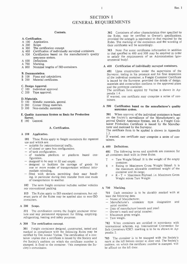
A 700 Marking.
701 Each container is to be durably marked with atleast the following data:
Name of Manufacturer.Manufacturer's container type designation andserial number.Date of manufacture (month and year).Owner's mark and serial number.Maximum gross weight.Tare weight.
702 \Vhen containers are certified in accordance withinternational schemes, e.g. International Convention forSafe Containers (CSC), marking is to be as shown in Appendix 2.
703 The container is to be stamped with the Society'smark at the left bottom corner at door end. The Society'semblem. on which the certificate number is stamped, willbe affixed on the left door.
Sec. 1
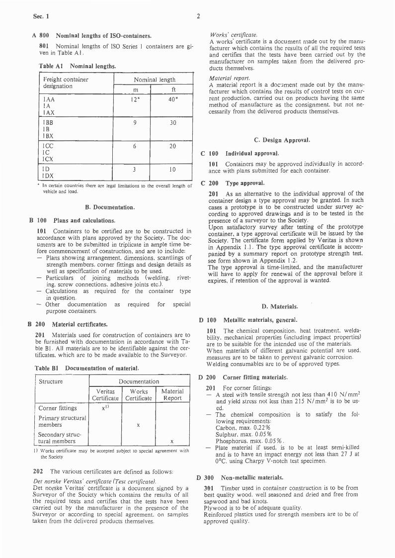
A 800 Nominal lengths of ISO-containers.
801 Nominal lengths of ISO Series I containers are given in Table AI .
Table Al Nominal lengths.
Freight container Nominal lengthdesignation
m ft
IAA 12* 40*lAlAX
IBB 9 30IBIBX
ICC 6 20ICICX
ID 3 10IDX
• In certain countries there are legal limitations to the overall length orvehicle and load.
B. Documentation.
B 100 Plans and calculations.
101 Containers to be certified are to be constructed inaccordance with plans approved by the Society. The documents are to be submitted in triplicate in ample time before commencement of construction. and are to include:
Plans showing arrangement. dimensions. scantlings ofstrength members. corner fittings and design details aswell as specification of materials to be used.Particulars of joining methods (welding. riveting. screw connections. adhesive joints etcJCalculations as required for the container typein question.Other documentation as required for specialpurpose containers.
B 200 Material certificates.
201 Materials used for construction of containers are tobe furnished with documentation in accordance with Table BI. All materials are to be identifiable against the certificates. which are to be made available to the Surveyor.
Table 81 Documentation of material.
Structure Documentation
Veritas Works MaterialCertificate Certificate Report
Corner fittings Xl)
Primary structuralmembers x
Secondary struc-tural members x
I) Works certificate may be accepted subject to special agreement withthe Society
202 The various certificates are defined as follows;
Det norske Veritas' certificate (Test certificate).Det norske Veritas' certificate is a document signed by aSurveyor of the Society which contains the results of allthe required tests and certifies that the tests have beencarried out by the manufacturer in the presence of theSurveyor or according to special agreement. on samplesrnken from the delivered products themselves.
2
Works' certificate.A works' certificate is a document made out by the manufacturer which contains the results of all the required testsand certifies that the tests have been carried out by themanufacturer on samples taken from the delivered products themselves.
Material report.A material report is a doc'lment made out by the manufacturer which contains the results of control tests on current production. carried out on products having the samemethod of manufacture as the consignment. but not necessarily from the delivered products themselves.
C. Design Approval.
C 100 Individual approval.
101 Containers may be approved individually in accordance with plans submitted for each container.
C 200 Type approval.
201 As an alternative to the individual approval of thecontainer design a type approval may be granted. In suchcases a prototype is to be constructed under survey according to approved drawings and is to be tested in thepresence of a surveyor to the Society.Upon satisfactory survey after testing of the prototypecontainer. a type approval certificate will be issued by theSociety. The certificate form applied by Veritas is shownin Appendix I. I. The type approval certificate is accompanied by a summary report on prototype strength test.see form shown in Appendix 1.2.The type approval is time-limited. and the manufacturerwill have to apply for renewal of the approval before itexpires. if retention of the approval is wanted.
D. Materials.
D 100 Metallic materials, general.
101 The chemical composition. heat treatment. weldability. mechanical properties (including impact properties)are to be suitable for the intended use of the materials.When materials of different galvanic potential are used.measures are to be taken to prevent galvanic corrosion.Welding consumables are to be of approved types.
D 200 Corner fitting materials.
201 For corner fittings;A steel with tensile strength not less than 410 N/ mm2
and yield stress not less than 215 N/mm 2 is to be used.The chemical composition is to satisfy the following requirements;Carbon. max. 0.22 %Sulphur. max. 0.05 %Phosphorus. max. 0.05 %.Plate material if used. is to be at least semi-killedand is to have an impact energy not less than 27 J atO°C. using Charpy V-notch test specimen.
D 300 Non-metallic materials.
301 Timber used in container construction is to be frombest quality wood. well seasoned and dried and free fromsapwood and bad knots.Plywood is to be of adequate quality.Reinforced plastics used for strength members are to be ofapproved quality.
E. Quality Assurance System as Basis for ProductionSurvey.
E 100 General.
101 Manufacturers of type approved containers havingin operation a Quality Assurance System approved by t~eSociety, may on certain condiiions use this syst~m as basIsfor a production survey arrangement agreed with the Society.The Society will carry out audits on the Manufacturer'sQuality Assurance System to ensure that the containersconform to the design which has been granted type approval.
102 The basic particulars stated in the production survey arrangement which will be reviewed by the Societywhen an agreement on container certification is to be made, are outlined as follows:
Works' organization.Line of responsibility of the quality control department and the production departments.Arrangements for introducing approved design/production changes and ensuring that they are actedupon at the appropriate production stage.
3 Sec. 1
Arrangements to ensure that supplies and servicesfrom subsuppliers meet with design requirements.Identifiable test data for materials and components areto be available.Jigs suitable for maintaining dimensional accuracyduring repeated use are to be provided at mainframeassembly points. Jig dimensions are to be periodicallyverified.Approved fabrication procedures (welding, rivetingetcJ and qualified personnel are to be engaged in fabricating panels and mainframes.Rejection procedure and rejected component identification arrangements are to be engaged in fabricatingpanels and mainframes.Records of inspection, tests and results of checks andcorrections are to be complete and reliable for eachcontainer. The record of inspection is to contain theManufacturer's identification numbers, dates of delivery and names and addresses of purchasers.
103 The Surveyor will keep the quality assurance system and workmanship under review. The number of containers selected at random by the Surveyor for testing inhis presence will be specially agreed upon, dependent onthe rate of container production.
Sec. 2 4
SECTION 2GENERAL CARGO CONTAINERS
Fig. 1 Roof clearance.
MIN. 6 MM
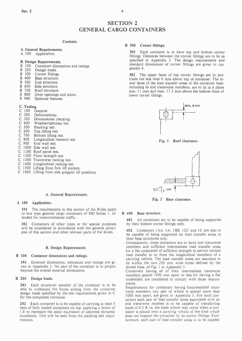
B 300 Corner fittings.
301 Each container is to have top and bottom cornerfittings. Distances between the corner fittings are to be asspecified in Appendix 3. The design requirements andstandard dimensions of corner fittings are given in Appendix 4.
302 The upper faces of top corner fittings are to protrude not less than 6 mm above top of container. The lower faces of the load transfer areas in the container base.including its end transverse members. are to lie in a planemin. 1I mm and max. 17.5 mm above the bottom faces oflower corner fittings.
+ 512,5 _', 5
Contents.
A. General Requirements.A 100 Application.
A. General Requirements.
B. Design Requirements.B J 00 Container dimensions and ratings.B 200 Design loads.B 300 Corner fittings.B 400 Base structure.B 500 End structure.B 600 Side structure.B 700 Roof structure.B 800 Door openings and doors.B 900 Optional features.
C. Testing.C 100 General.C 200 Deformations.C 300 Dimensional checking.C 400 Weathertightness test.C 500 Stacking test.C 600 Top lifting test.C 700 Bottom lifting test.C 800 Longitudinal restraint test.C 900 End wall test.C 1000 Side wall test.C I 100 Roof panel test.C 1200 Floor strength test.C 1300 Transverse racking test.C 1400 Longitudinal racking test.C 1500 Lifting from fork lift pockets.C 1600 Lifting from side grappler lift positions.
A 100 Application.
101 The requirements in this section of the Rules applyto box type general cargo containers of ISO Series I. intended for intercontinental traffic.
102 Containers of other types or for special purposeswill be considered in accordance with the general principles of this section and other relevant parts of the Rules.
B. Design Requirements.
B 100 Container dimensions and ratings.
101 External dimensions. tolerances and ratings are given in Appendix 3. No part of the container is to projectbeyond the overall external dimensions.
B 200 Design loads.
201 Each structural member of the container is to beable to withstand the forces arising from the containerdesign loads specified by the test requirements given in Cfor the completed container.
202 Each container is to be capable of carrying at least 5tiers of fully loaded containers on top. applying a factor of1.8 to represent the static equivalent of assumed dynamicconditions. This will be seen from the stacking test requirements.
Fig. 2 Base clearance.
B 400 Base structure.
401 All containers are to be capable of being supportedby their bottom corner fittings only.
402 Containers IAA. IA. I BB. ICC and IC are also tobe capable of being supported on load transfer areas intheir base structures only.Consequently. these containers are to have end transversemembers and sufficient intermediate load transfer areas(or a Oat underside) of sufficient strength to permit verticalload transfer to or from the longitudinal members of acarrying vehicle. The load transfer areas are assumed tolie within the two 250 mm wide zones defined by thedotted lines. of Fig. I in Appendix 5.Containers having all of their intermediate transversemembers spaced 1000 mm apart or less (or having a Oatunderside). are considered to comply with these requirements.Requirements for containers having (intermediate) transverse members. any pair of which is spaced more thanJ 000 mm apart. are given in Appendix 5. For such containers each pair of load transfer areas associated with anend transverse member is to be capable of transferringloads of 0.5 R i.e. the loads which may occur when a container is placed onto a carrying vehicle of the kind whichdoes not support the container by its corner fittings. Furt·hermore. each pair of load transfer areas is to be capable

5 Sec. 2
of transferring loads of 1.5 Rln where n is the number ofpairs of intermediate load transfer areas. i.e. loads whichmay occur during transport operations.
403 The structural design of all containers is to be suchthat no part of the base structure will deflect more than 6mm below the bottom faces of the bottom corner fittingsunder a load of 1.8 R- T uniformly distributed over thefloor.
B 500 End structure.
501 For containers 1AA. IA. IBB. IB. ICC and ICo thesideway deflection of the top of the container in relationto the bottom. when it is subjected to a transverse rackingforce of 150 kN. is not to cause the sum of the changes inlength of the two diagonals in each end wall to exceed 60mm.
B 600 Side structure.
601 For containers I AA. I A. I BB. 1B. I CC and I Co thelongitudinal deflection of the top of the container in relation to the bottom of the container. when it is subjected toa longitudinal racking force of 75 kN. is not to exceed 25mm.
B 700 Roof structure.
701 The roof panel design is to be such that any accumulation of water is avoided.
702 The structural strength is to be sufficient to withstand the roof panel test specified in Co
B 800 Door openings and doors.
801 Door end openings are. if practicable. to have dimensions corresponding to the free internal cross-sectionof the container cargo space.For containers 1A. lB. 1C and ID the door opening is notto be less than 2134 mm (7 ft 0 in) high and 2286 mm (Jft 6 in) wide.For containers I AA. I BB and ICC the door opening isnot to be less than 2261 mm (7 ft 5 in) high and 2286 mm(7 ft 6 in) wide.
802 Doors are to be equipped with securing devices andsealing for weathertight closing. Devices for clasping ofdoors in open position are to be provided.
B 900 Optional features.
901 Fork lift pockets according to Appendix 6.1 may beprovided on I CC. I Co I CX. I D and I DX containers forhandling in the loaded and unloaded condition. Whereone set of fork lift pockets has been fitted. as stipulated inAppendix 6.1. a second set of fork lift pockets may in addition be provided on 1Cc. I C and I CX containers forhandling in empty condition only.Fork lift pockets are to pass completely through the basestructure of the container. so that lifting devices may beinserted from either side.
902 Containers may be provided with features forhandling at the base by means of grappler arms or similardevices. Such features are to be as shown in Appendix6.2.
903 Containers 1.-\. IAA and IAX may be providedwith gooseneck tunnels as shown in Appendix 6.3.
C. Testing.
C 100 General.
101 The following requirements apply to prototype testing and individual testing of containers. The frequency ofthe Surveyor's attendance to the testing of the completedcontainers will depend on the quality assurance arrangements of the container manufacturer. see Sec. I.The Surveyor will prepare a detailed test report. A summary report on prototype strength is prepared. The form used is shown in Appendix 1.2.
102 For each container the manufacturer is to carry outdimensional checking and weathertightness test. Forstrength tests. the number of containers to be tested willbe specially agreed. depending on the rate of containerproduction.
103 Measuring instruments to be used for tests andchecking are to be duly calibrated to the satisfaction of theSurveyor.
104 The procedures specified for the strength tests maybe modified as appropriate for special purpose containersand special handling arrangements.The required loadings in each test are to be applied in sucha manner as to allow free deflection of the container section under test.The test loads inside the container are to be uniformly dis'tributed. The container is to be measured before the testing. and the dimensions checked after the testing.
C 200 Deformations.
201 For acceptable elastic deformation under test load.reference is made to B 400 (base structure). B 500 (endstructure) and B 600 (side structure).
202 Upon completion of the test. the container is toshow neither permanent deformation which will render itunsuitable for use nor abnormality which will render itunsuitable for use. and the dimensional requirements affecting handling. securing and interchange are to be satisfied.
C 300 Dimensional checking.
301 Each completed container is to be checked to verifythat the overall dimensions of the container and the position of the corner fittings are within the specified tolerances.
C 400 Weathertightness test.
40 I The doors of each completed container are to besubjected to a weathertightness test. Every 10th completedcontainer is to be subjected to a complete weathertightnesstest of all external surfaces. For containers which also arestrength tested. the weathertightness test is to be carriedout after completion of all strength tests.
402 All surfaces of the container are to be subjected to awater test from a 12.5 mm nozzle. with a water pressureof I bar at the nozzle. which is to be traversed at a speedof approximately 100 mm per second at a distance of 1.5m from the surface under test.The interior of the container is to remain dry.
403 Except for the prototype of type approved containers. the hose testing specified in 402 may be substitutedby a light test.Procedure: The Surveyor will enter the container. Thedoors are then closed. and the Surveyor is to accustomhimself to the darkness for at least 3 minutes before powerful light beams surrounding all external surfaces areswitched on.The container is to be free from any observable light penetration.
Sec. 2 6
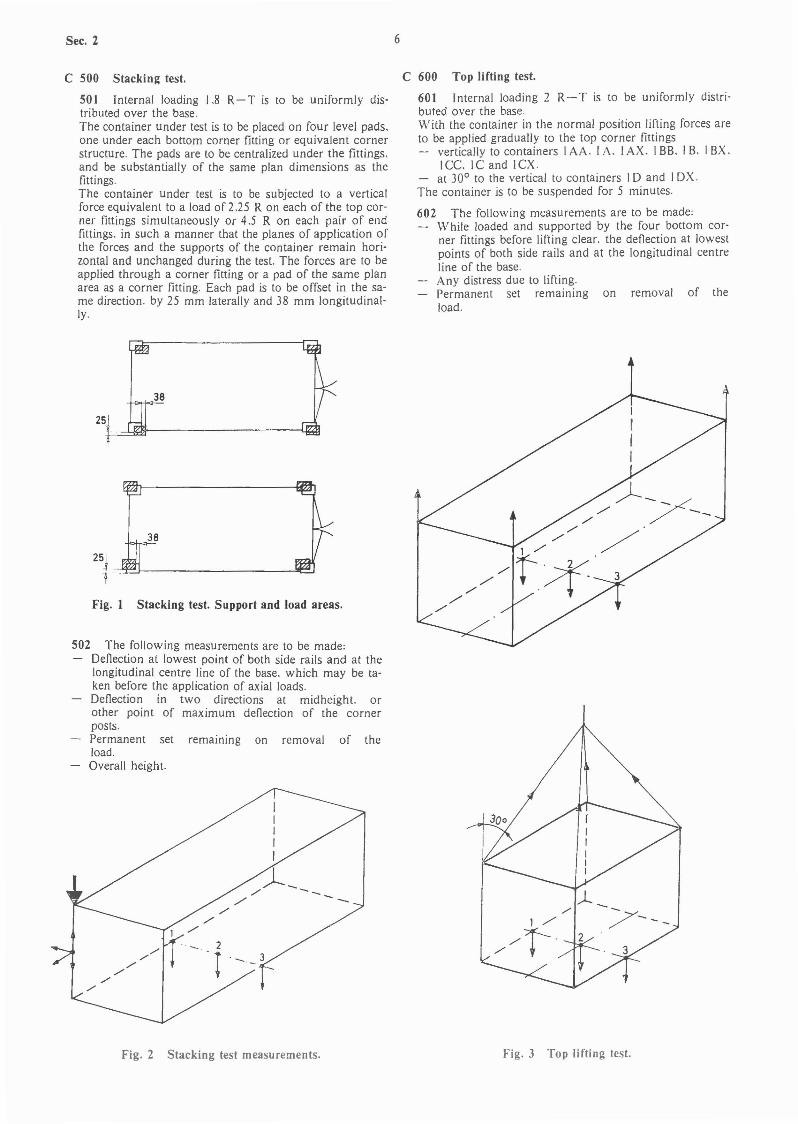
C 500 Stacking test.
SO I Internal loading 1.8 R- T is to be uniformly distributed over the base.The container under test is to be placed on four level pads.one under each bottom corner fitting or equivalent cornerstructure. The pads are to be centralized under the fittings.and be substantially of the same plan dimensions as thefittings.The container under test is to be subjected to a verticalforce equivalent to a load of 2.25 R on each of the top corner fittings simultaneously or 4.5 R on each pair of endfittings. in such a manner that the planes of application ofthe forces and the supports of the container remain horizontal and unchanged during the test. The forces are to beapplied through a corner fitting or a pad of the same planarea as a corner fitting. Each pad is to be offset in the same direction. by 25 mm laterally and 38 mm longitudinally.
C 600 Top lifting test.
60 I Internal loading 2 R- T is to be uniformly distributed over the baseWith the container in the normal position lifting forces areto be applied gradually to the top corner fittings
vertically to containers IAA. I A. I AX. I BB. I B. IBX.ICe. IC and ICX.
- at 30° to the vertical to containers ID and IDX.The container is to be suspended for 5 minutes.
602 The following measurements are to be made:While loaded and supported by the four bottom corner fittings before lifting clear. the deflection at lowestpoints of both side rails and at the longitudinal centreline of the base.Any distress due to lifting.Permanent set remaining on removal of theload.
502 The following measurements are to be made:Deflection at lowest point of both side rails and at thelongitudinal centre line of the base. which may be taken before the application of axial loads.Deflection in two directions at midheight. orother point of maximum deflection of the cornerposts.Permanent set remaining on removal of theload.Overall height.
Fig. 1 Stacking test. Support and load areas.
25
Fig. 2 Stacking test measurements. Fig. 3 Top lifting test.

7 Sec. 2
Fig. 4 Bottom lifting test.
In each case the line of action of the lifting force and theouter face of the corner fitting is to be no further apartthan 38 mm.The container is to be suspended for 5 minutes.
702 Any distress due to lifting is to be recorded.
Fig. 6 End walJ test.
C 900 End walJ test.
901 Internal loading 0,4 P is to be uniformly distributedover the wall (or end doors) under test in such a way as toallow free deflection of the end wall. If one end has doors.both end walls are to be tested.
902 Deflection and permanent set at the centre and atleast two other locations are to be recorded.
C 1000 Side wall test.
1001 Internal loading 0,6 P is to be uniformly distributedover the wall under test is such a way as to allow free deflection of the side wall and its top and bottom side rails.Each side is to be tested separately, but only one side needbe tested when both are similar in construction.
1002 Deflection and permanent set at the centre of theside wall and the centre of the top and bottom side rails orat the weakest section of the side wall are to be recorded.
Direction CL of applied forces
30° to horizontal37° to horizontal45° to horizontal60° to horizontal
Container designation
IAA. lA and lAXIBB. IB and IBXICe. IC and ICXID and IDX
C 700 Bottom lifting test.
70 I Internal loading 2 R- T is to be uniformly distributed over the base.With the container in the normal position. lifting forcesare to be applied gradually through the bottom corner fitting side apertures as follows:
C 800 Longitudinal restraint test.
80 I Internal loading R- T is to be uniformly distributedover the base.With the container in the normal position. anchored bylocking devices through the bottom apertures in the bottom corner fittings at onc end. loads equivalent to R are tobe applied to each side rail through the bottom corner fittings at the other end. first in compression then in tension.
802 The change in length of bottom side rails duringand after the test tin each direction) is to be recorded.
,,1- __./!,f' __
./ --/'
././
Fig. 5 Longitudinal restraint test.
Fig. 7 Side wall test.
C 1100 Roof panel test.
1101 Internal loading is not to be applied. On the roof aloading of 3 kN is to be uniformly distributed over a 600mm x 300 mm area at the weakest section of the roof.
1102 Maximum deflection and permanent set of the section under test are to be recorded.
Sec. 2 8
Fig. 9 Floor strength test.
1302 Difference in diagonals before, during and after testing is to be recorded.
Fig. 11 Longitudinal racking test.
Fig. 10 Transverse racking test.
C 1400 Longitudinal racking test.
1401 Internal loading is not to be applied.The container under test is to be placed on four level pads,one under each bottom corner fitting, an to be anchoredthrough their bottom apertures so that no vertical movement is possible. Longitudinal restraint of a side wall is tobe provided only at the 'bottom corner fitting opposite to,and in the same side frame as, the top corner fitting towhich force is applied.Forces of 75 kN are to be applied either separately or simultaneously to each of the top corner fittings on one endof the container in parallels to both the side wall and tothe base plane. The forces are to be applied first towardsand then away from the top corner fittings.Only one of two identical side walls need be tested. Wherea side wall is essentially asymmetrical about its own vertical centre line, the side wall is to be tested from both ends.
1402 Longitudinal displacement of top side rails is to berecorded.
C 1500 Lifting from fork lift pockets.
1501 ICc. IC and ICX containers equipped with onlyone set of fork lift pockets, and ID and IDX containers:Internal loading 1.25 R-T is to be uniformly distributedover the base.
-
Fig. 8 Roof panel test.
././
,/,,/
,/
,/,/
./,/
./
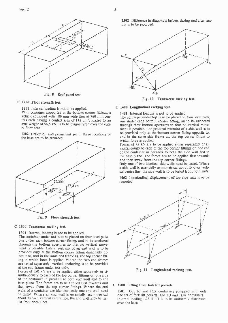
C 1200 Floor strength test.
1201 Internal loading is not to be applied.With container supported at the bottom corner fittings, avehicle equipped with 180 mm wide tires at 760 mm centres each having a contact area of 142 cm2, loaded to anaxle weight of 54.6 kN, is to be manoeuvred over the entire floor area.
1202 Deflection and permanent set in three locations ofthe base are to be recorded.
C 1300 Transverse racking test.
1301 Internal loading is not to be applied.The container under test is to be placed on four level pads,one under each bpttom corner fitting, and to be anchoredthrough the bottom apertures so that no vertical movement is possible. Lateral restraint of an end wall is to beprovided only at the bottom corner fitting diagonally opposite to, and in the same end frame as, the top corner fitting to which force is applied. Where the two end framesare tested separately, vertical anchoring is to be providedat the end frame under test only.Forces of 150 kN are to be applied either separately or simultaneously to each of the top corner fittings on one sideof the container in parallels to both end wall and to thebase plane. The forces are to be applied first towards andthen away from the top corner fittings. Where the endwalls of a container are identical, only one end wall needbe tested. Where an end wall is essentially asymmetricalabout its own vertical centre line, the end wall is to be tested from both sides.
The container is to be supported for 5 minutes by twobars 200 mm wide inserted in the fork pockets to a depthof 1828 ± 3 mm. The bars are to be centred within thepockets.Undue local distortion during the test and any permanentdistortion are to be recorded.
1502 ICC. IC and ICX containers equipped with twosets of fork lift pockets:The procedure stated in 150 I applies to the external forklift pockets. while the internal ones are subject to the following procedure:Internal loading 0.625 R- T is to be uniformly distributedover the base.The container is to be supported on two horizontal bars asspecified in 150 I, placed into the additional internal forklift pockets.The container is to be supported for 5 minutes.Undue local distortion during the test and any permanentdistortion are to be recorded.
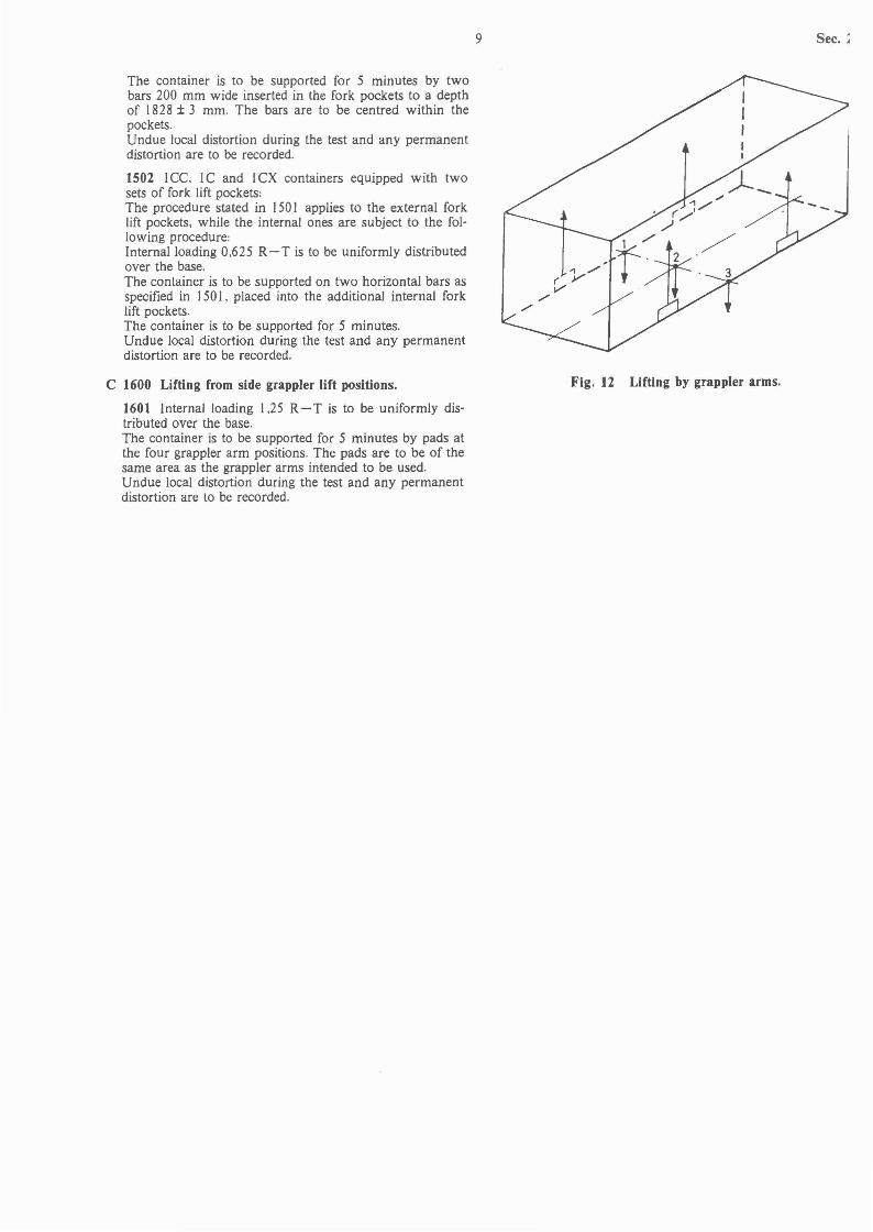
C 1600 Lifting from side grappler lift positions.
1601 Internal loading 1.25 R- T is to be uniformly distributed over the base.The container is to be supported for 5 minutes by pads atthe four grappler arm positions. The pads are to be of thesame area as the grappler arms intended to be used.Undue local distortion during the test and any permanentdistortion are to be recorded.
9 Sec. ;
Fig. 12 Lifting by grappler arms.
Sec. 3 10
SECTION 3THERMAL CONTAINERS
Contents.
A. General Requirements.A 100 Application.A 200 Documentation.
B. General Design and Equipment.B 100 Container dimensions and ratings.B 200 Structural strength.B 300 Airtightness.B 400 Insulation.B 500 Lining.B 600 Drainage.B 700 Temperature monitoring equipment.
C. Heating Appliances.ClOD General.
D. Refrigerating Appliances.D 100 Capacity of refrigerating units.D 200 Design pressures.D 300 Safety devices.D 400 Pressure gauges.D 500 Connections for water-cooling of container.D 600 Connections for air-cooling of container.D 700 Electrical equipment.
E. Strength Tests.E 100 General.
F. Weathertightness test.F 100 General.
G. Airtightness test.G I 00 General.G 200 Procedure.G 300 Measurements.
H. Heat Transfer Test.H 100 General.H 200 Procedure.H 300 Measurements.
I. Performance Test of Thermal Appliances.I 100 General.I 200 Procedure.I 300 Measurements.
J. Marking.1 100 Refrigerated containers.1 200 Heated containers.
A. General Requirements.
A lOO Application.
101 This section of the Rules applies to:insulated containers without refrigerating or heatingappliances.insulated containers with refrigerating appliances (refrigerated containers).insulated containers with heating appliances(heated containers).dual purpose refrigerated! heated containers.
102 The requirements stipulated in the following are additional to relevant requirements of Secs. I and 2.
103 Regarding refrigerating plant. see also the Rules forSteel Ships Pt. 6 Ch. 2, as far as relevant for refrigeratedcontainers.
A 200 Documentation.
20 I In addition to the documentation required in Sec. I.the following documents are to be submitted for approval:
Plans of insulation with design details. material specification and data of heat transmission.Description of corrosion protection.Plan of drainage arrangement.Description of the refrigerating and! or heatingappliances.Arrangement plan for the refrigerating and! orheating appliances.Heat balance calculation.Plan showing cross-section of refrigerant compressor,Plan of compressor crankshaft.Plan of pressure vessels in the plant.Piping diagram for the plant.Plan with particulars of the temperature measuring appliances.Electrical wiring diagram including necessaryconnection data.Description of automatic temperature regula-tion.
B. General Design and Equipment.
B 100 Container dimensions and ratings.
101 External dimensions. tolerances and ratings are given in Appendix 3. Units for refrigerating and! or heatingpurposes may be located partially or totally outside the external dimensional envelope of the container. Such unitswill have to be removable or retractable to facilitate certain modes of transportation.
B 200 Structural strength.
20 I The structural strength of the completed containeris to be sufficient to withstand the test requirements givenin E.
B 300 Airtightness.
301 Insulated containers are to be of airtight construc-tion to comply with the test requirements given in G.
B 400 Insulation.
40 I The coefficient of heat transfer K is not to exceed0.4 \\'! m2 QC for refrigerated and! or heated containers.For containers without refrigerating or heating appliances.the coefficient K will be agreed in each case.
402 The cargo space boundaries are to be diffusiontightagainst watervapour from the side which is warm in normal operation.
403 The insulation material is to have the followingproperties:
It is not to absorb and give off odours which may affect the cargo.It is to have mechanical resistance to vibrationsand deformations at the service temperatures.It is to be resistant to decay and be chemicallyneutral.It is to have high resistance to moistu re transmission and air movement in the material.It is to be durable at the temperatures and temperature variations in service. .\Iaterial placed against

external surfaces is to be able to withstand at least100°e.Plastic foams are to be «self-extinguishing» according to a recognized standard.
B 500 Lining.
50 I The inner surface of the container is to permit thorough cleaning methods. e.g. water cleaning. wet steamcleaning and detergents normally used. wi"thout detrimental effects on the container performance.
502 The materials used in the inner space of the container are not to give off any substances detrimental tofoodstuffs and health.
11 Sec. :
D 200 Design pressures.
201 For the conventional Group I refrigerants R 12 andR 22, the design working pressures are not to exceed thevalues given in Table DJ.
Table Dl Design working pressures.
Air-cooled condensers Water-cooled condensers
Refrigerant max. working Refrigerant max. workingpressure pressure
RI2 17 bar RI2 13 barR 22 28 bar R 22 22 bar
B 600 Drainage.
60 I Provisions are to be made to ensure that water fromcleaning of the interior of the container can be completelydrained. Cargo space drains for this purpose are to haveclosing devices manually operable from the outside of thecontainer.
602 Where drainage of cargo space will be necessary also w hen carrying cargo. such draining equipment is toopen automatically when the acceptable level is exceeded.
B 700 Temperature monitoring equipment.
70 I At least two independent devices are to be providedfor measuring the internal temperature of the container.with independent reading from the outside.Unless otherwise agreed. a maximal total error of ±O.5°C will be acceptable for the indication and measuringaccuracy.
C. Heating Appliances.
C 100 General.
101 Unless otherwise specified by the purchaser of thecontainer. heating appliances are to be designed to be capable of maintaining an inside temperature of 16°<:; at atemperature of - 20°C outside the container. on the basisof a daily service period of 18 hours.
102 Other particulars are as far as relevant to be in compliance with the requirements in D. and as agreed withthe Society.
D. Refrigerating Appliances.
D 100 Capacity of refrigerating units.
101 Each refrigerated container is to be equipped withits own refrigerating system operating independently. except for electric power supply.
102 Unless otherwise specified. the inside design temperature is to be taken as - 18°C at a temperature of 38°Coutside the container.For water-cooled condensers for the refrigerant the designtemperature of the cooling water is not to be taken lessthan 36°e.
103 If only one refrigerating unit is installed. it is to becapable of maintaining the required lowest internal temperature in the container at the conditions specified in 102.on the basis of a daily service period of 18 hours.
104 If two entirely independent refrigerating systems.each with its own evaporator. are installed for one container. they may be considered as a single unit for jointlyto satisfy the requirements given in 103.
D 300 Safety devices.
301 Devices are to be arranged for automatic cut-off ofpower supply to compressor when the maximum allowable working pressure is exceeded.
302 Pressure vessels for liquid refrigerant are to be protected by a safety valve, if the pressure vessel can be isolated from the system. For refrigerants of Group I, a corrosion-resistant safety disc may be substituted for the safety valve.
D 400 Pressure gauges.
401 When Group I refrigerants are used, suction anddelivery pressure gauges will be required only for the performance test. If the gauges are removed after the testing,the connections are, however, to remain accessible for later measurements.
D 500 Connections for water-cooling of container.
501 Water-cooled appliances are to incorporate possibility for draining the unit to prevent freezing of water.The inlet and outlet connections are, unless otherwisespecified, to comply with ISO I496/II -1979.
D 600 Connections for air-cooling of container.
601 If the container is designed for ducted air systemsand for use with externally located removable equipment,the inlet and outlet openings are to have closing devicesattached to the container. The air apertures are, unlessotherwise specified, to comply with ISO 1496/II-1979.
D 700 Electrical equipment.
701 Electrical equipment for 'refrigerated containers is tobe suitable for the ambient conditions aboard ships, and isto be in general compliance with the Rules for Steel Ships,PtA, ChA. Electrical motors are to be of a design suitablefor continuous operation.
702 Unless otherwise specified, the electrical equipmentis to be designed to operate satisfactorily at v()ltage andfrequency variations not less than:
Voltage: ± 2.5 % at steady conditions- 15 % and + 20 % at transient conditions
Frequency: ± 5% at steady conditions± 10% at transient conditions
703 Plug and socket connections are to be in compliance with ISO 1496/II-1979. unless otherwise specified.
Sec. 3 12
E. Strength Tests. Table GlAir flow to maintain internal pressure.
E 100 General.
101 During the strength tests, refrigerating and/ or heating equipment that may contribute to the overall strengthis to be in position. Alternatively, suitable equivalents forthe equipment may be fitted to simulate the service condition. In such cases, the ability of the refrigerating and/ orheating equipment to withstand the cargo loading and/ orthe forces or static equivalents of accelerations representedby the strength tests, is to be verified independently.
102 Thermal containers are to be subjected to the sametests as specified for general cargo containers as stated inSec.2.
103 If the roof is strengthened for hanging cargo, thefollowing additional roof strength test is to be carried out:
With the container in the normal position supported at thebase corner fittings, a load of twice the service load or 30kN per metre of usable inside container length, whicheveris the greater, is to be suspended from the roof support. simulating normal service loading.Maximum deflection and permanent set of the section under test are to be recorded.
F. Weathertlghtness test.
F 100 General.
101 Weathertightness test is to be carried out as specified for general cargo containers. The testing of the container envelope is to be made before the contamer is insulated. Care is, however. to be taken that tests are carriedout on door seals, exterior gasketed joints and other openings fitted with closing devices.
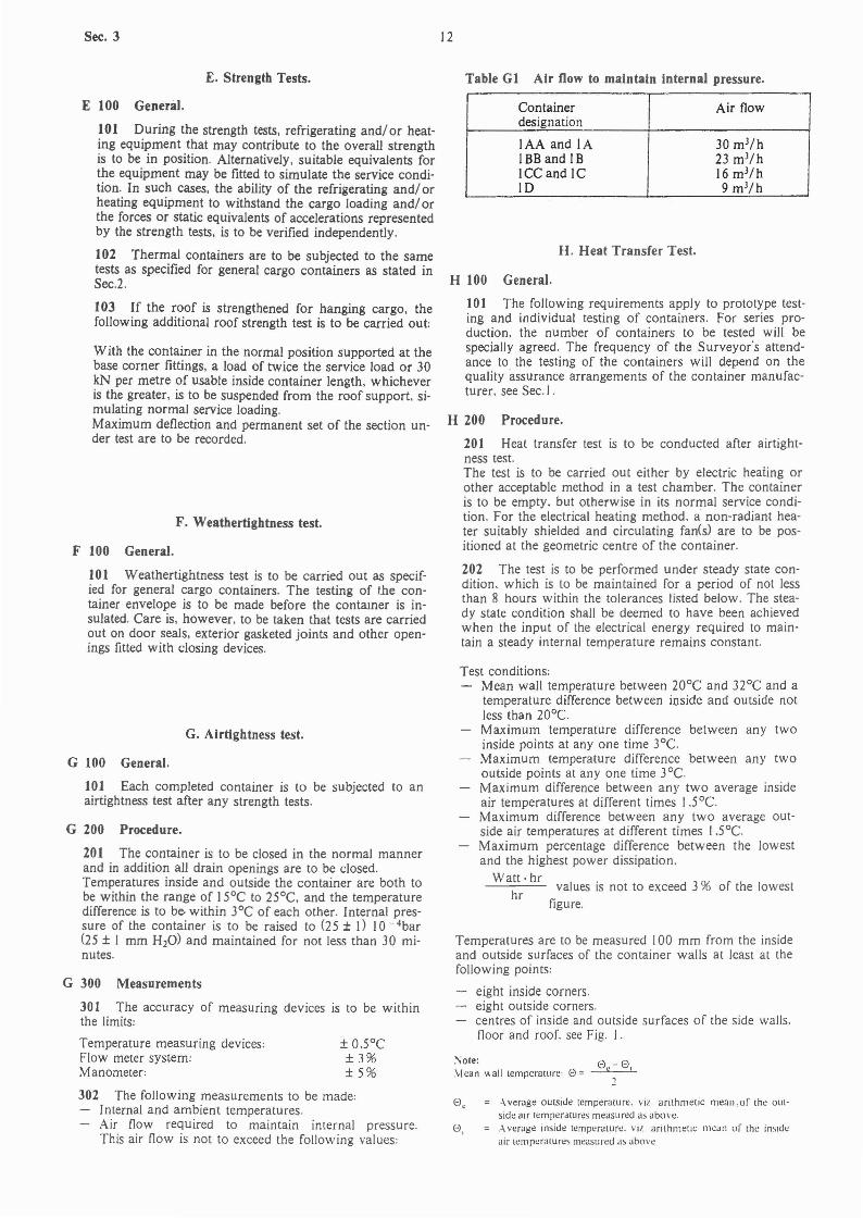
Container Air flowdesignation
IAA and lA 30 mJ/hIBB and IB 23 mJ/hICCand IC 16 mJ/hID 9 mJ/h
H. Heat Transfer Test.
H 100 General.
101 The following requirements apply to prototype testing and individual testing of containers. For series production, the number of containers to be tested will bespecially agreed. The frequency of the Surveyor's attendance to the testing of the containers will depend on thequality assurance arrangements of the container manufacturer. see Sec. I.
H 200 Procedure.
201 Heat transfer test is to be conducted after airtightness test.The test is to be carried out either by electric heating orother acceptable method in a test chamber. The containeris to be empty. but otherwise in its normal service condition. For the electrical heating method. a non-radiant heater suitably shielded and circulating fan(s) are to be positioned at the geometric centre of the container.
202 The test is to be performed under steady state condition. which is to be maintained for a period of not lessthan 8 hours within the tolerances listed below. The steady state condition shall be deemed to have been achievedwhen the input of the electrical energy required to maintain a steady internal temperature remains constant.
G. Airtightness test.
G 300 Measurements
301 The accuracy of measuring devices is to be withinthe limits:
G 100 General.
101 Each completed container is to be subjected to anairtightness test after any strength tests.
302 The following measurements to be made:Internal and ambient temperatures.Air flow required to maintain internal pressure.This air flow is not to exceed the following values:
,.\ verage outside temperature. viz. arithmetic mean.of the out·side air temperatures measured as above...\ verage inside temperature. viz arithmetiC mea'1 of the inSideair lClllperaLUrcs measured ,ts above
<3 I
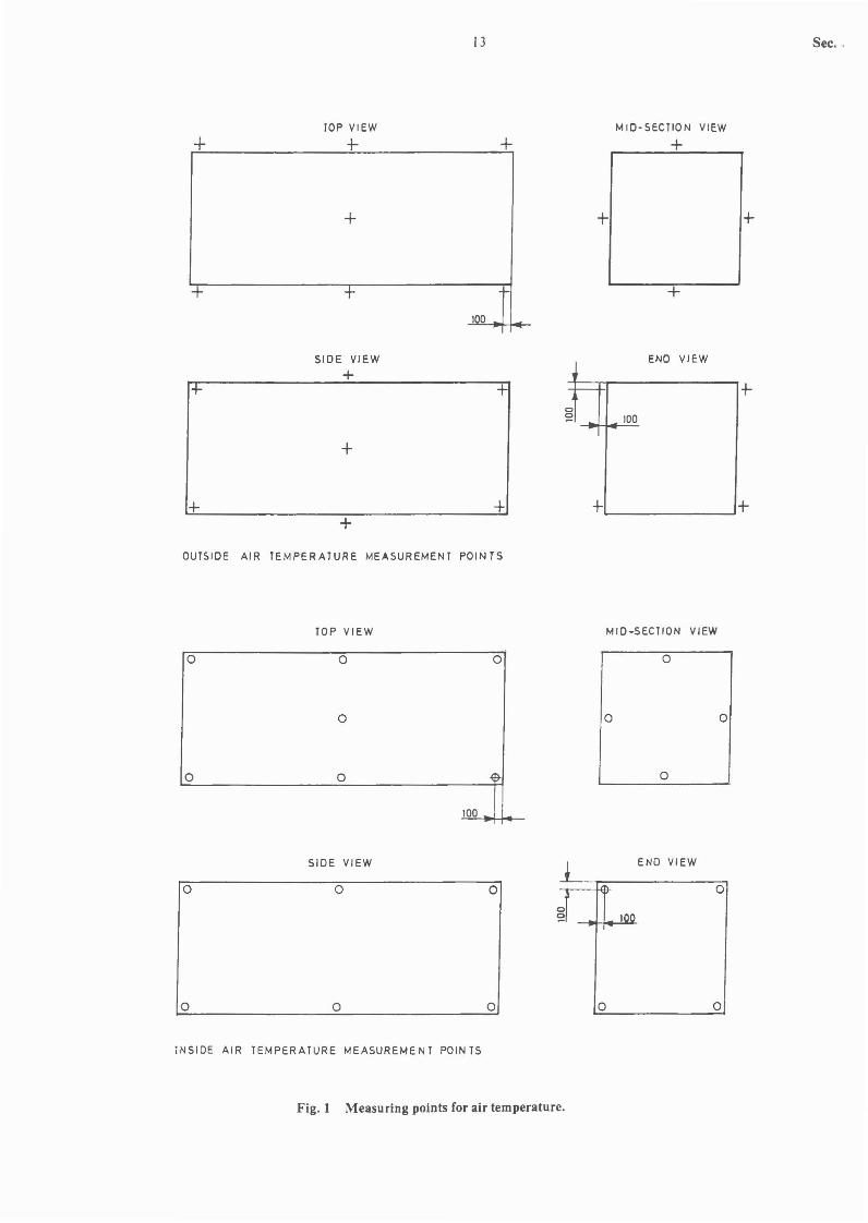
Temperatures are to be measured 100 mm from the insideand outside surfaces of the container walls at least at thefollowing points:
eight inside corners.eight outside corners.centres of inside and outside surfaces of the side walls.floor and roof. see Fig. 1.
:'iole: e - <3\lean wall temperature: e = C I
1
Test conditions:Mean wall temperature between 20°C and 32°C and atemperature difference between inside and outside notless than 20°C.Maximum temperature difference between any twoinside points at anyone time 3°C.Maximum temperature difference between any twooutside points at anyone time 3°C.Maximum difference between any two average insideair temperatures at different times l.scC.Maximum difference between any two average outside air temperatures at different times (.s0C.Maximum percentage difference between the lowestand the highest power dissipation.
Watt·hr .hr values IS not to exceed 3 % of the lowest
figure.
± O.s°C±3%±5%
Temperature measuring devices:Flow meter system:Manometer:
G 200 Procedure.
201 The container is to be closed in the normal mannerand in addition all drain openings are to be closed.Temperatures inside and outside the container are both tobe within the range of 15°C to 25°C. and the temperaturedifference is to be within 3°C of each other. Internal pressure of the container is to be raised to (25 ± I) 10 - 4bar(25 ± I mm H20) and maintained for not less than 30 minutes.
+rop VIEW
+
+
13
+
+
MID-SECTION VIEW
+
+
Sec. ,
+ + +100
SIDE VIEW END VIEW
+1+ + -,.--- +
0
~ 100
+
++
+ +"'----------'+
OUTSIDE AIR TEMPERATURE MEASUREMENT POINTS
TOP VIEW MID-SECTION VIEW
o
o
o
o
o
SIDE VIEW
100
o
o
o
o
END VIEW
o
o
o
o
o
o
o
0
100
0 0
INSIDE AIR TEMPERATURE MEASUREMENT POINTS
Fig. 1 Measuring points for air temperature.

Sec. 3
H 300 Measurements.
301 The accuracy of power measuring systems is to bewithin ± 2 % of the quantity measured.The accuracy of other measuring devices is to be as specified in G 300.
302 Data for determining the heat leakage (total heattransfer rate) of the container are to be taken at intervalsof not more than 30 minutes and for a continuous periodof not less than 8 hours.
Note: QHeat transfer rate U = _---0...._
14
After this time. a non-radiant heater placed in the airstream inside the container is to be turned on. having a capacity of at least 25 % of the total heat transfer rate of thecontainer. established by the heat transfer test. With theheater in operation. the average internal temperature ofthe container is to be maintained at the specified insidetemperature for a period of at least 4 hours.
300 Measurements.
301 The internal and external temperatures and theelectrical input to the heater are to be recorded.
Q
El. - El,
Power dissipated or absorbed by the operation of internal heatersand fanCs) or internal cooling units.
J. Marking.
I. Performance Test of Thermal Appliances.
I 100 General.
101 All containers which have undergone a heat transfer test. are to be subjected to a performance test to verifythe ability of the refrigerating and/ or heating equipmentto maintain the specified internal temperature at a 75 %duty cycle (i.e. daily service period of 18 hours).For the purpose of testing a refrigerating equipment. continuous operation may be accepted. provided the test procedure stated in 200 is applied.
I 200 Procedure.
201 Using the refrigerating unit. the container placed ina test chamber. where the temperature is held constant atthe anticipated maximum ambient temperature. is to becooled down to the design temperature. The temperatureis to be maintained for a period of 8 hours.
J 100 Refrigerated containers.
101 In addition to the marking required in Sec.1 for allcontainers. at least the following particulars are to beclearly and durably indicated on the exterior of refrigerated containers:
Type and date of manufacture of refrigerating unit.Refrigerant.Internal service temperature and ambient airtemperature (when condenser is air-cooled).Motor for refrigerant compressor:output. r.p.m.. rated voltage. frequency and phases.full load current and total starting current.
102 For containers fitted with cargo hanging arrangements. the maximum service load is to be stated on a signboard fitted in an easily visible position in the containercargo space.
J 200 Heated containers.
201 Additional marking of heated containers will beconsidered for each type and make of container.
15
SECTION 4TANK CONTAINERS
Sec. ~
Contents.
A. General Requirements.A 100 Application.A 200 Documentation.
B. General Design.B 100 Container dimensions and ratings.
C. Design of Framework.C I 00 General.C 200 Design loads.C 300 Optional features.
D. Design of Tank.D I 00 General.D 200 Design loads.D 300 Openings for inspection and maintenance.D 400 Tank fittings.D 500 Pressure relief devices.D 600 Vacuum relief devices.D 700 Gauging devices.
E. Testing.E 100 General.E 200 Stacking test.E 300 Top lifting test.E 400 Bottom lifting test.E 500 Longitudinal restraint test (externa]).E 600 Longitudinal inertia test.E 700 Lateral inertia test.E 800 Transverse racking test.E 900 Longitudinal racking test.E 1000 Lifting from side grappler lift positions.E I 100 Walkway test.E 1200 Pressure test of tank.E 1300 Testing of special equipment.
F. Marking.F 100 General.F 200 Tank fittings and pressure relief devices.
A. General Requirements.
A 100 Application.
101 This section of the Rules apply to tank containersintended for carriage of gases or liquids under pressure orfor gravity discharge. and which can be transported andstacked in loaded condition.
102 A tank container is defined as consisting of a tank. aframework and the connecting members between thesetwo structures. as well as any appliances for heating or refrigeration of the tank content.
103 The requirements stipUlated in the follo\ving are additional to relevant requirements of Secs. I and 2. Anyheating or refrigerating appliances. as well as associatedelectrical equipment. will be specially considered.
104 Tank containers for carriage of substances whichan~ regarded as dangerous cargoes according to internationally agreed codes or relevant national codes. will bespecially considered
A 200 Documentation.
20 I In addition to the documentation required in Sec.I.the following documents are to be submitted for approval:
Plans of tank with scantIings and design details ofopenings for inspection and maintenance. as well asdetails of the connection of valves. nozzles and othertank fittings.Specification of cargoes intended to be carriedand proposed operating conditions.Plan of tank supports with details.Specification of materials and weld proceduresfor tank and supports with details of weld connections.Strength calculations for tank and supportingframework.Description of corrosion protection.Plan of tank inSUlation. if any. with design details.Arrangement plan and details of valves. nozzlesand other tank fittings.Documentation of blow-off capacity of safetyequipment.Arrangement plan. system diagram and particulars of any heating or refrigerating appliances.Specification of any electrical equipment fittedon the container.
202 Material certificates for tank structure and supportsand certificates for fittings etc. are to be provided in accordance with relevant chapters of the «Steel Ship Rules».
B. General Design.
B 100 Container dimensions and ratings.
101 External dimensions of framework. tolerances andratings are given in Appendix 3. No part of the tank. itsequipment or fittings is to protrude outside the dimensional envelope of the container.
C. Design of Framework.
C 100 General.
101 The upper faces of the top corner fittings are to protrude above the top of the tank shell with any insulationand its associated piping and fittings by minimum 6 mm.
102 When the tank container is loaded to its rating R.no part of the tank with any insulation and its associatedshell fittings is to project downwards below a plane 25mm above the base plane (bottom faces of the lower corner fittings).
103 When the tank container is loaded uniformly to atotal weight (mass) of 1.8 R (the static equivalent of thedynamic condition). no part is to deflect more than 6 mmbelow the base plane (bottom faces of the lower cornerfittings).

Sec. 4
e 200 Design Loads.
201 The framework and tank supports are to be designed to withstand the following static equivalents of the inertia effects of the tank contents. considered individually:I R longitudinally. I R laterally and 2 R vertically.Vertical loadings are total loadings including gravitationaleffects.
202 Each structural member of the framework is to beable to withstand the forces arising from the design loadsspecified by the test requirements given in E for the completed tank container.
203 Walkways. if fitted. are to be designed to withstanda loading of 3 kN uniformly distributed over an area of600 mm x 300 mm.
204 Ladders. if fitted. are to be designed to withstand aloading of 2 kN on any rung.
e 300 Optional features.
301 Fork lift pockets are not to be provided in tank containers. ISO Series I.
302 Tank containers may be provided with features forhandling at the base by means of grappler arms or similardevices. Such features are to be as shown in Appendix6.2.
30.3 Tank containers IA and IAA may be providedwIth gooseneck tunnels as shown in Appendix 6.3.
16
D 300 Openings for inspection and maintenance.
301 Tanks are to be provided with manholes or otheropenings to allow for complete internal inspection.The size of manholes is to be a minimum of 450 mm diameter and is to be determined by the need for men andmachines to enter the tank to inspect. maintain or repairits interior.
D 400 Tank fittings.
401 All tank openings. except pressure relief devices.are to be provided with adequate closures to prevent accidental escape of the tank content.
402 The design of tank nozzles and outlet fittings. aswell as their attachments to the tank. are to be such thatthe risk of breakage is minimized. Protective covers orhousings are to be provided if considered necessary.
403 All tank openings located below the normal liquidlevel of the tank content and fitted with a valve capable ofbeing operated manually. are to be provided with an additional means of closure on the outlet side of the valve.Such additional means of closure may be a fluid-tight cap.bolted blank flange. or other suitable protection againstaccidental escape of tank content.
404 All valves. whether fitted internally or externally.are to be located as close to the tank shell as practicable.
405 Stop valves with screw spindles are to be closed byclockwise motion of the' handwheel.
D. Design of Tank.
D 100 General.
101 The requirements stipulated in the following are additional to relevant requirements of the «Steel Ship Rules».
102 Regarding basic requirements for the tank shell design. materials. valves and fittings. it is referred to theSteel Ship Rules as follows:
Pt,2 Materials and WeldingPtA, ChJ Boilers and Pressure VesselsPt.5, ChJ Oil CarriersPt.5. ChA Chemical CarriersPt,5. Ch.5 Liquefied Gas Carriers
103 The tank(s) is (are) to be adequately secured to thecontainer framework.
104 Tanks are to be capable of being filled and emptiedwithout removal from the framework.
D 200 Design loads.
201 The tank structure is to be designed to withstandthe following static equivalents of the inertia effects of thetank contents:I R longitudinally. I R laterally and 2 R vertically.The loadings may be considered individually. evenly distributed. and acting through the geometric centre of thetank. The vertical loading 2 R includes gravitational effects. The above loadings are not considered to give rise toany increase in the pressure in the vapour space of thetank.It is also referred to the test requirements specified in E.
202 Tanks or tank compartments without vacuum reliefvalves are to be designed to withstand an external pressure of at least 0.4 bar above the internal pressure. without any permanent deformation.
203 When heating or refrigerating appliances are provided. due consideration is to be given to the avoidance ofthe development of excessive temperatures and stresses inthe tank and its supporting structure.
D 500 Pressure relief devices.
501 Each tank or fluid-tight compartment is to be fittedwith a pressure relief device connected to the vapourspace and located on the top of the tank as near to themidlength of the tank (or compartment) as practicable.
502 The opening pressure and the capacity of the pressure relief devices will be considered for each type anddesign of tank container and its intended use.
D 600 Vacuum relief devices.
601 Tanks not designed to withstand an external overpressure of at least 0.4 bar. are to be fitted with a vacuumrelief device to prevent permanent deformation of tank (ortank compartment) caused by external pressure.
D 700 Gauging devices.
70) The arrangement. design and materials of gaugingdevices are to be compatible with the cargoes intended tobe carried in the tank.
E. Testing.
E 100 General.
101 The following requirements apply to prototype testing and individual testing of tank containers. The frequency of the Surveyor's attendance to the testing of completedcontainers will depend on the quality assurance programme of the container manufacturer. see Sec.l.
)02 For each tank container the manufacturer is to carry out dimensional checking and pressure testing. Forstrength tests of framework. the number of containers tobe tested will be specially agreed. depending on the rate ofcontainer production.

17 Sec.
103 The strength tests stipulated in Sec.2 for generalcargo containers apply to tank containers. with the modifications and additions specified in the following. Alternative test procedures will be accepted if considered to beequivalent.
104 The required loadings and forces in each test are tobe applied in such a manner as to allow free deflection ofthe section under test.
105 The internal test loading is to be obtained by fillingthe tank. and a supplementary external loading may beprovided. when necessary. to achieve the specified testload. The test loading thus applied is to be such as to simulate uniform loading.
E 200 Stacking test.
201 No internal loading in tank.
202 Applied forces and measurements as required forgeneral cargo containers.
E 300 Top lifting test.
301 Internal loading 2 R-T (see 105).
302 Applied forces and measurements as required forgeneral cargo containers.
E 400 Bottom lifting test.
401 Internal loading 2 R-T (see 105).
402 Applied forces and measurements as required forgeneral cargo containers.
E 500 Longitudinal restraint test (externa)).
50 I Internal loading R- T in tank.
502 Applied forces and measurements as required forgeneral cargo containers.
E 600 Longitudinal inertia test.
60 I With R- T internal loading in tank. the container isto be positioned with its longitudinal axis vertical ana supported by its four bottom corner fittings.The container is to be supported for 5 minutes.
602 Any distress due to the test is to be recorded.
E 700 Lateral inertia test.
70 I With R- T internal loading in tank. the container isto be positioned with its transverse axis vertical and supported by its four bottom corner fittings. The container isto be supported for 5 minutes.
702 Any distress due to the test is to be recorded.
E 800 Transverse racking test.
80 I No internal loading in tank.
802 Applied forces and measurements as required forgeneral cargo containers. Any distress due to the test is tobe observed.
E 900 Longitudinal racking test.
90 I No internal loading in tank.
902 Applied forces as required for general cargo containers.
903 Difference in diagonals before. during and after testing is to be recorded. Any distress due to the test is to beobserved.
E 1000 Lifting from side grappler lift positions.
1001 Internal loading I .25 R- T (see 105).
1002 Applied forces and measurements as required fogeneral cargo containers.
E 1I00 Walkway test.
1101 No internal load in tank.
1102 A load of 3 kN is to be uniformly distributed ovean area 600 mm x 300 mm at the weakest section of thewalkway.
1103 Maximum deflection and permanent set of walkway under test are to be recorded.
E 1200 Pressure test of tank.
120 I This test is to be carried out after all mainframEstrength tests have been completed and before any insula·tion is fitted. The tank container together with its associat·ed pipework and fittings is to be hydrostatically tested to ctest pressure not less than 1.5 times the maximum allowa'ble working pressure or design pressure.
1202 Where the tank is provided with fluid-tight compartments. additional pressure test is to be carried out individually for each compartment with the adjacent compartments empty and under atmospheric pressure.
1203 Test procedures other than the above may be accepted by the Society after special consideration. The testpressure is to be measured at the top of the tank in its normal position and is to be maintained to enable a completeexamination of the tank. Relief devices. where fitted. areto be rendered inoperative or removed.
1204 The tank container is to show no leakage. no permanent deformation or abnormality which will render itunsuitable for use.
E 1300 Testing of special equipment.
1301 Testing of heating or refrigerating appliances andother special feature of tank containers will be consideredby the Society for each type and intended service of thecontainer.
F. Marking.
F 100 General.
101 In addition to the marking required in Sec. I for allcontainers. at least the following particulars are to beclearly and durably indicated on the tank container:
Maximum allowable working pressure.Test pressure.Total cubic capacity.Setting of pressure relief device.
F 200 Tank fittings and pressure relief devices.
20 I All tank connections are to be clearly and durablymarked to indicate their appropriate functions.
202 Each pressure relief device is to be marked with thepressure at which it is set to operate.

Sec. 5 18
SECTION 5PLATFORMS AND PLATFORM-BASED CONTAINERS
Contents.
A. General Requirements.A 100 Application.A 200 Cross reference.
B. Design Requirements.B 100 Container dimensions and ratings.B 200 Design loads.B 300 Corner fittings.B 400 Base structure.B 500 Lashing devices for cargo.B 600 Optional features.
C. Testing.
102 For platform-based containers with incomplete suoperstructure. the requirements for the overall top lengths(any folding ends in erected position) given in Appendix 3.may be modified to the extreme limits given in Table B I.
Table B 1 Overall top lengths.,
Container Lma\ (mm) Lmil1 (mm)designation tare cond. loaded to I R
I AA and I A 12202 121721BB and I B 9135 9105ICC and IC 6068 6042ID 3001 2976
C 100C 200C 300C 400C 500
C 600
C 700
General.Deformations.Dimensional checking.Testing of platforms.Testing of platform-based containers with incomplete superstructure and fixed ends.Testing of platform-based containers with incomplete superstructure and folding ends.Testing of platform-based containers. open-sided.with complete superstructure.
103 For platform-based containers with ends in foldedposition. the external length and width are to be as specified in Appendix 3.
104 An interlocked pile of folded containers is to be capable of having the plan dimensions established in ISO 668(see Appendix 3) and a height not exceeding 2591 mm.
105 Any movable part which. if unsecured. could leadto a hazardous situation. is to be provided with an adequate securing system having external indication of the positive securement of that system in the appropriate operating position.
A. General Requirements.
A 100 Application.
101 This section of the Rules applies to platforms andplatform-based containers of the configurations specifiedin 102-105.
102 A platform {container! is a loadable platform havingno superstructure. but having the same length and widthas the base of ISO Series I freight container.
103 A platform-based container (Series I) with incomplete superstructure and fixed ends may have either:- fixed complete end structure (Type 61) or- fixed free-standing posts (Type 62).
104 A platform-based container (Series I) with incomplete structure and folding ends may have either:- folding complete end structure (Type 63) or- folding free-standing posts (Type 64).
105 A platform-based container (Series I), open-sided.with complete superstructure may have either:
roof (Type 65) oropen top (Type 54) or
- open top and open ends (Type 55).
A 200 Cross reference.
201 The requirements stipulated in the following aremodifications of or supplements to relevant requirementsof Secs. I and 2.
B. Design Requirements.
B 100 Container dimensions and ratings.
101 The dimensions and ratings of platforms and platform-based containers of ISO Series I. are generally to beas specified in Appendix 3
B 200 Design loads.
201 Each structural member of a platform or platformbased container is to be able to withstand the forces arising from the design loads specified by the testing requirements for the various container configurations in erectedas well as folded condition. Acceptable denections underthe tests are generally as specified in Sec.2 for general cargo containers.
202 For platform-based containers I AA. I A. I BB. ICCand C the strength of the side structure is to be adequateto prevent that the longitudinal denection of the top of thecontainer in relation to its bottom will exceed 42 mm under full longitudinal rigidity tcst conditions.
B 300 Corner fittings.
301 Platforms and platform-based containers are to beequipped with bottom corner fittings and top corner fittings where appropriate.
B 400 Base structure.
401 The base structure is to be designed to withstand allforces. particularly lateral forces expected induced by thecargo in service. This is particularly important whereprovisions are made for securement of cargo to the basestructure of the container.The design forces are partly given by the specified testloads. and are otherwise taken as specified by the container builders or owners
402 Strengthened load transfer areas are to be providedin the base structure as for general cargo containers.
B 500 Lashing devices for cargo.
50 I Platforms and platform-based containers ,with opensides or open ends are to equipped \\ ith permanent lashing devices for securement of the cargo to the base structure.
19 Sec. :
The securing devices are to be designed and fitted to theplatform containers in such a way that:
the ropes or other means of lashing the loads will notprotrude beyond the overall length and width of thecontainer platform.no part of the lashing devices will protrude above the plane located 6 mm below the upper surfacesof the top corner fittings.
B 600 Optional features.
60 I Fork lift pockets. arrangements for grappler armsand goose neck tunnels may be fitted as for general cargocontainers.
C. Testing.
C 100 General.
101 The required loadings in each test are to be appliedin such a manner as to allow free deflection of the container section under test.
102 The test loads on the platform and platform-basedcontainers are to be uniformly distributed. The containeris to be measured before the testing. and the dimensionschecked after the testing.
103 The requirements for prototype testing and individual testing of platforms and platform-based containersare specified in 400-700.
104 Alternative test procedures will be accepted if considered to be equivalent.
105 As to frequency of the surveyors attendance. quali·ty assurance programme, batch testing etc.. reference i~
made to Sec.2.
106 Platforms and containers are to be tested in the con·dition in which they are designed to operate.
t 07 \\'eathertightness test as specified in Sec.2. is to be;carried out if relevant for the platform container in question.
C 200 Deformations.
20 I For acceptable elastic deformations under test load.see B 400 (base structure) B 500 (end structure) and B 600(side structure) in Sec.2.
202 Upon completion of the test the platform and theplatform-based container is to show neither permanentdeformation. which will render it unsuitable for use norabnormality, which will render it unsuitable for use. andthe dimensional requirements affecting handling. securingand interchange are to be satisfied.
C 300 Dimensional checking.
30 I Each completed platform and platform-based container is to be checked to verify that the overall dimensions of the container and the position of the corner fittingsare within the specified tolerances.

Sec. 5 20
C 400 Testing of platforms.
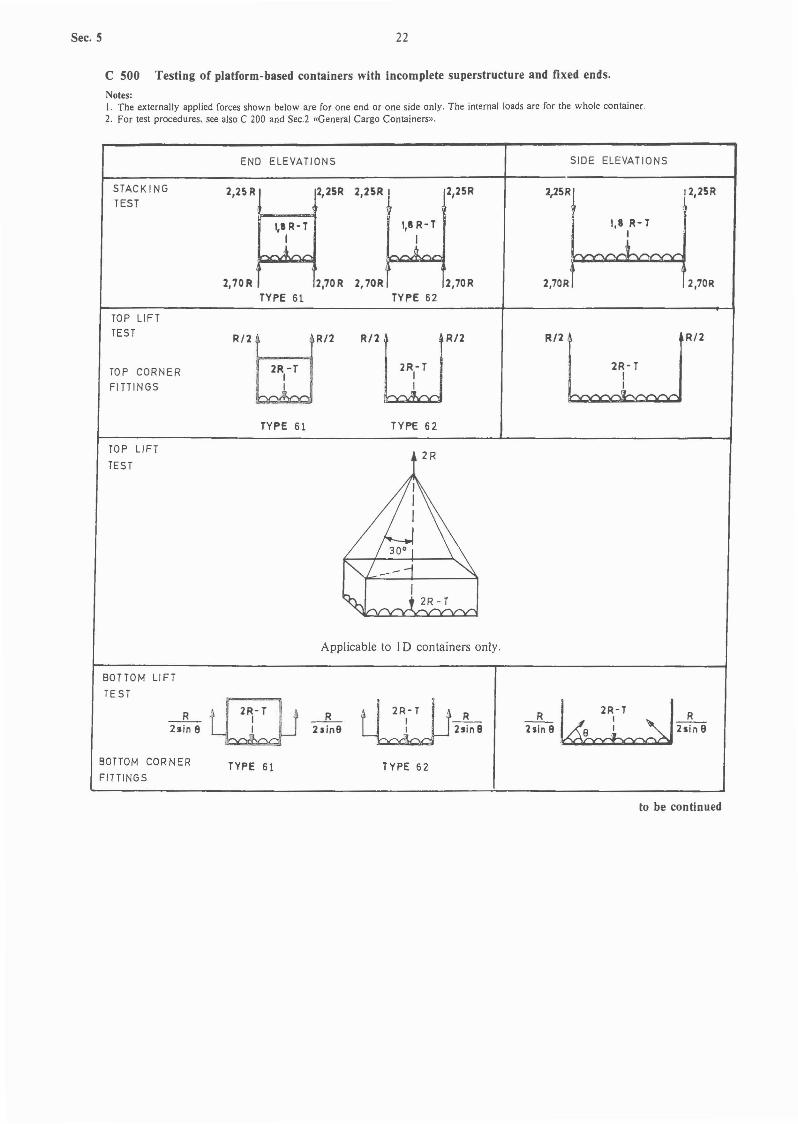
Notes:I. The externally applied forces shown below are for one end or one side only. The internal loads are for the whole container.2. For test procedure. see also Sec.2 «General Cargo Containers».
END ELEVATIONS SIDE ELEVATIONS
STACKING 2,25 R 1 2,25 R 2,25 R1TEST
>-
2,70 R 2,70 R 2,70R
Applicable to all sizes
2,25 R
Test procedure:
The platform container under test in the tare condition is to be placed on four level pads, one under each bottomcorner fitting or equivalent corner structure. The pads are to be centralized under the fittings. and be substantiallyof the same plan dimensions as the fittings.
The platform container under test is to be subjected to a vertical force equivalent to a load of 2,25 R on each ofthe top corner fittings simultaneously. or 4,5 R on each pair of end fittings, in such a manner that the planes ofapplication of the forces and the supports of the container remain horizontal and unchanged during the test. Theforces are to be applied through a corner fitting or a pad of the same plan area as a corner fitting. Each pad is tobe offset in the same direction by 25 mm laterally and 38 mm longitudinally.
TOP LIFT
TEST
2R
30°I
~--t 2R-T~
"'" I
Applicable to ID containers only.
TOP LIFTTEST
_ R_2sin9 L:-T
1I _R_~ 21in9
Applicable to IA, IB and IC containers only.
Test procedure:
The platform container under test is to have a load uniformly distributed over the floor in such a way that thecombineq weight of container and test load is equal to 2 R, and it is to be carefully lifted from the side aperturesof all four top corner fittings in such a way that no significant acceleration or deceleration forces are applied.
Lifting forces are to be applied at:
30° to the horizontal for IA containers.37° to the horizontal for IB containers.45° to the horizontal for IC containers.60° to the horizontal for ID containers.
In each case the line of action of the lifting force and the outer face of the corner fitting is to be no farther apartthan 38 mm. The lifting is to be carried out in such a manner that the lifting devices bear on the top corner fittingsonly.
The platform container is to be suspended for 5 minutes.
to be continued

C 400 continued
END ELEVATIONS
21
SIDE ELEVATIONS
Sec.
RESTRAINT I LONGITUDINAL)
TES T
AT BOTTOM1,00 R 4
per lide~I I
~ 1,00Rper .Ide
R-TI
1APPLICABLE TO ALL SIZES
WHEEL LOADINGS
TEST
1,00 R _'-'-~-~~~~"""'l-- 1,00 Rper side per side
f f
2x27,3kN
f fAPPLICABLE TO ALL SIZES
Fork lift test
Applicable to IC and ID platform containers fittedwith fork lift pockets.
0,615R(total)
-~-
0,625R(total)
,
Grappler lift arm test
Applicable to IA, I B and IC platform containers fitted with grappler arm lift positions.
0,3125Rper Ilde
Sec. 5 22
C 500 Testing of platform-based containers with incomplete superstructure and fixed ends.
Notes:1. The externally applied forces shown below are for one end or one side only. The internal loads are for the whole container.2. For test procedures. see also C 200 and Sec.2 «General Cargo Containers».
STACKING
TEST
END ELEVATIONS
2,2~ R 2,2~R 2,2~R ~ 2,25R
I,' R-T 1,8 R-T
l ~
2,70R 2,70R 2,70R 2,70RTYPE 61 TYPE 62
SIDE ELEVATIONS
2,25R 2,25R
I,' R- T
J2,70R 2,70R
TOP LIFTTEST
TOP CORNER
FITTINGS
R/2tEjR/2
2R -TII
R/2WR12
2R-T,I
R/2
2R-TI~
R/2
TYPE 61 TYPE 62
TOP LiFT
TEST2R
30° ,
Applicable to I D containers only.
R~R__ I __
2sin9~ 2sin9tWJR- TI _R_
. I 2sin8
_R_ t[EJJi- 2Rl,-T I _R_
2sin e LJ 2sin9~
BOTTOM LIFT
TE ST
BOTTOM CORNER
FITTINGSTYPE 61 TYPE 62
to be continued

23 Sec.
C 500 continued
RIGI DITYI TRANSVERSE)
TEST
END ELEVATIONS
r----__---<~ 150 k N
I~ ISOkN
SIDE ELEVATIONS
150 k N~--f---~t 150 kN----+---~
TYPE 61
RIGIDITY
(TRANSVERSE)TEST _IS0kN
TYPE 62
....--150 kN
Applicable to IA, I AA. I B, I BB. ICand ICC containers only.
150 kN ---..{I+--...f
TYPE 61
RIGIDITY(LONGI TUDI NAL)
TEST
ISO k N----I*"---f
TYPE 62
50kN ....--+------~
Applicable to IA, IAA, I B, I BB, ICand ICC containers only.
RESTRAINT(LONGITUDINAL)
TEST
Applicable to all containers.
STRENGTH ON
END LOAD
Applicable only to type 6 J containers.
R-T
.A-1,00 R .....--.E~~~!:::=:::g_ ___i>- 1,00 R
per lid' per 'id'
~I,OOR - l,OORpar side per side
to be continued
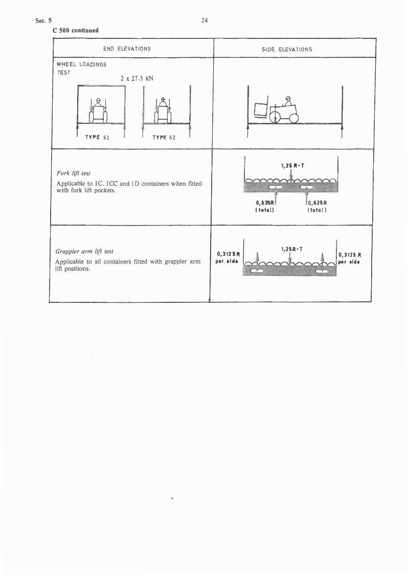
Sec. 5
C 500 continued
END ELEVATIONS
24
SIDE ELEVATIONS
WHEEL LOADINGS
TEST
TYPE 51
2 x 27,3 kN
TYPE 52
d~l
Fork lift test
Applicable to IC. ICC and ID containers when fittedwith fork lift pockets.
Grappler arm lift test
Applicable to all containers fitted with grappler armlift positions.
0,3125"pe' side
1,25 1'-1
1,25R-T
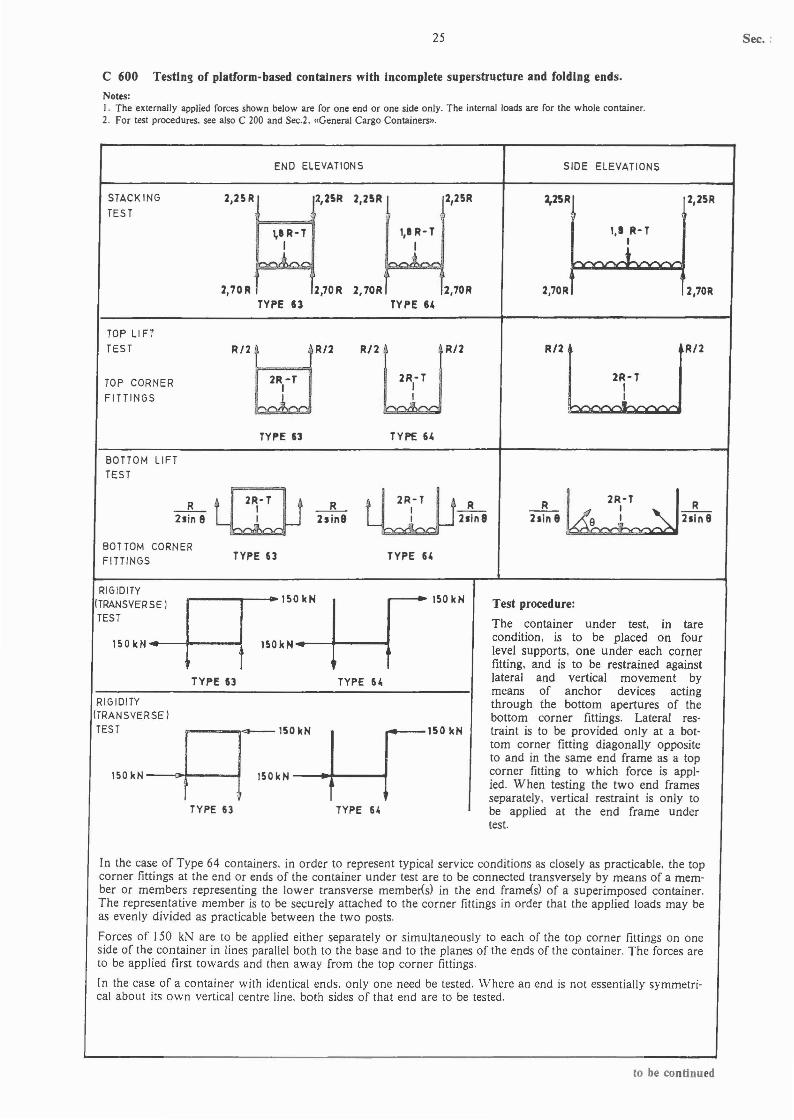
25
C 600 Testin~ of platform-based containers with Incomplete superstructure and folding ends.
Notes:I. The externally applied forces shown below are for one end or one side only. The internal loads are for the whole container.2. For test procedures. see also C 200 and Sec.2. «General Cargo Containers».
Sec. :
END ELEVATIONS
STACK ING
TES T2.25 R 2,25R
1,1 R-T
14
2,70R 2.70RTYPE 13
2,25R ~ t,25R
r 1,erTI
"70.~,.70.TYPE 64
SIDE ELEVATIONS
2,25R 2,25R
I,. R-TI
J -2,70R 2,70R
TOP LI FT
TEST
TOP CORNER
FITTINGS
R/2tJJ,R/2
2R-TI
, .'
RJ2WR/2
2R-TII
R/2
2R-TI
.~.
R/2
TYPE 63
BOTTOM LIFTTEST
_ R_ ID _ R_21in e 21in9
BOTTOM CORNERFITTINGS TYPE 63
TYPE 64
ltJjJR-TI _R_I 21in8
TYPE 64
~--_-.150kN
_-~~_150kN
RIGIDITY(TRANSVERSE)TEST
150 k N----f~-----lt
TYPE U
RIGIDITY(TRANSVERSE)TEST
150 kN ---<+----f
TYPE 63
r--·150kN
150 kN----+---~
~
TYPE 61,
,..--150kN
150 k N---t~---f
TYPE 61,
Test procedure:
The container under test. in tarecondition. is to be placed on fourlevel supports. one under each cornerfitting. and is to be restrained againstlateral and vertical movement bymeans of anchor devices actingthrough the bottom apertures of thebottom corner fittings. Lateral restraint is to be provided only at a bottom corner fitting diagonally oppositeto and in the same end frame as a topcorner fitting to which force is applied. When testing the two end framesseparately. vertical restraint is only tobe applied at the end frame undertest.
In the case of Type 64 containers. in order to represent typical service conditions as closely as practicable. the topcorner fittings at the end or ends of the container under test are to be connected transversely by means of a member or members representing the lower transverse member<s) in the end frame<s} of a superimposed container.The representative member is to be securely attached to the corner fittings in order that the applied loads may beas evenly divided as practicable between the two posts.
Forces of 150 kN are to be applied either separately or simultaneously to each of the top corner fittings on oneside of the container in lines parallel both to the base and to the planes of the ends of the container. The forces areto be applied first towards and then away from the top corner fittings.
In the case of a container with identical ends. only one need be tested. V/here an end is not essentially symmetrical about its own vertical centre line. both sides of that end are to be tested.
to be continued
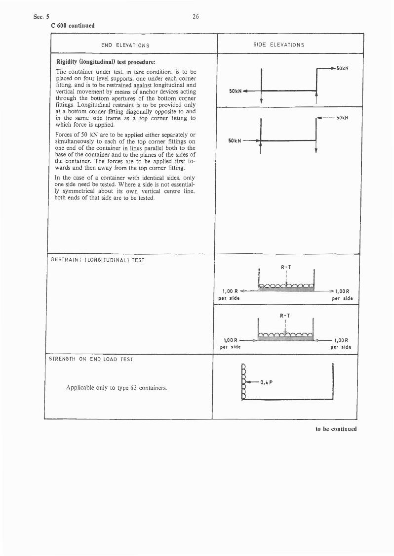
Sec. 5
C 600 continued
END ELEVATION S
26
SIDE ELEVATIONS
Rigidity (longitudinal) test procedure:
The container under test, in tare condition, is to beplaced on four level supports, one under each cornerfitting, and is to be restrained against longitudinal andvertical movement by means of anchor devices actingthrough the bottom apertures of the bottom cornerfittings. Longitudinal restraint is to be provided onlyat a bottom corner fitting diagonally opposite to andin the same side frame as a top corner fitting towhich force is applied.
Forces of 50 kN are to be applied either separately orsimultaneously to each of the top corner fittings onone end of the container in lines parallel both to thebase of the container and to the planes of the sides ofthe container. The forces are to be applied first towards and then away from the top corner fitting.
In the case of a container with identical sides, onlyone side need be tested. Where a side is not essentially symmetrical about its own vertical centre line.both ends of that side are to be tested.
RESTRAINT (LONGITUDINAL) TEST
r-----'~ 50 itN
50kN ....-+------~
1,00 R ..,
per side
R- T
LLJ->l.DDRper side
STRENGTH ON END LOAD TEST
Applicable only to type 63 containers.
R-TI
.l_1,00 R --<>~~~ee:::::::::eL>-- 1,00 R
per side per sid~
t_O,4P_Ito be continued
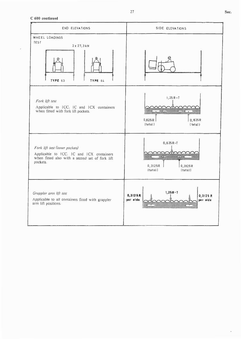
C 600 continued
END ELEVATIONS
WHEEL LOAOINGS
TEST2x27,3kN
27
SIDE ELEVATIONS
Sec.
Ty,.E 63 TY,.! 64
Fork lift test
Applicable to 1Cc. IC and ICX containerswhen fitted with fork lift pockets.
Fork lift test Onner pockets)
Applicable to JCc. IC and 1CX containerswhen fitted also with a second set of fork liftpockets.
Grappler arm I(ft test
Applicable to all containers fitted with grapplerarm lift positions.
1,2S R- T
O,625R(total)
O,625R-T
1,:2U-T0,3125 R
~x:li'ClC~C)lbC~X:::~~~ IM' .Id,
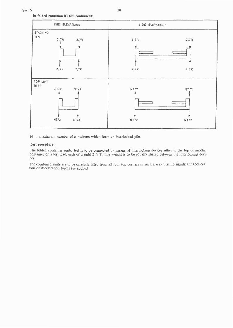
Sec. 5
In folded condition (C 600 continued):
28
END ELEVATIONS SIDE ELEVATIONS
STACK I NG
TEST2,7R 2,7R 2,7R 2,7R
n I...., r
2,7R 2,7R 2,7R 2,7R
TOP LIFTTES T
NT /2 NT/2 NT /2 NT/2
l r h r
NT/2 NT/2 NT/2 HTI2
N = maximum number of containers which form an interlocked pile.
Test procedure:
The folded container under test is to be connected by means of interlocking devices either to the top of anothercontainer or a test load, each of weight 2 N T. The weight is to be equally shared between the interlocking devices.
The combined units are to be carefUlly lifted from all four top corners in such a way that no significant acceleration or deceleration forces are applied.
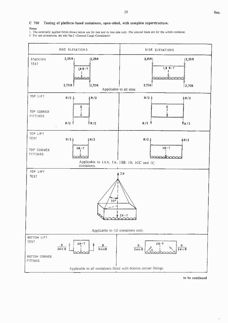
29
C 700 Testin:t of platform-based containers, open-sided, with complete superstructure.
Notes:I. The externally applied forces shown below are for one end or one side only. The internal loads are for the whole container.2. For test procedures. see also Sec.2 «General Cargo Containers».
Sec.
STACKING
TEST
TOP LIFT
TOP CORNER
FITTINGS
END ELEVATION S SIDE ELEVATIONS
2,2~R 2,25R 2,25R
~. R-T I,' R- TI I
lr. Jf
2,70R 2,70R Z,70RApplicable to all sizes
R/2 R/2 R/2
0 0I I
& ~
R/2 R12 R/2
2,25R
2,70R
R/2
R/2
TOP LIFT
TEST
TOP CORNERFITTINGS
TOP LIFT
TEST
R/2tyjR/2
2R-TI,
I
Applicable tocontainers.
R/2
IAA. lA. IBB. lB. ICC and IC
2R
30° I
2R-TI~
R/2
",I ---1I
~ j 2R-T
Applicable to ID containers only.
BOTTOM LIFTTEST
BOTTOM CORNE~
FITTINGS
_R_ 1f ,~2R,,-T i •2sin8~
_R_2sin9
Applicable to all containers fitted with bottom corner fittings.
to be continued
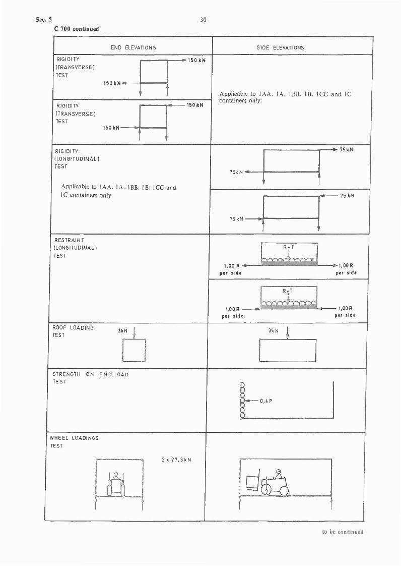
Sec. 5
C 700 continued
30
END ELEVATIONS SlOE ELEVATIONS
RIGIDITY ISO kN(TRANSVERSE)
TEST
ISO kN
Applicable to IAA. IA. IBB. IB. ICC and le
150kNcontainers only.
RIGIDITY
(TRANSVERSE)
TESTISOkN
RIGIDI TY
75kN-l r-75kN
(LONGITUDINAL)
TEST
Applicable to IAA. IA. IBB. I B. ICC andIC containers only.
75kN~ i75kN
RES TRAIN T(LONGITUDINAL) R-T
f
TEST .A1,00 R I,OOR
per side par side
R-T_i
.l!
l,OOR--- r-l,OOR
per side per side
ROOF LOADING
'Pl 3k N !TES T
I J
STRENGTH ON EN D LOADTEST
to," IWHEEL LOADINGS
TEST
2x27,3kN
161 .~r=- --
to be continued
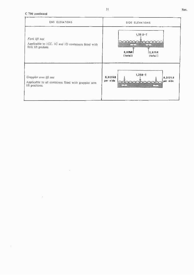
C 700 continued
END ELEVATIONS
31
SIDE ELEVATIONS
Sec.
O,625RItotal)
Fork lift test
Applicable to ICc.fork lift pockets.
IC and ID containers fitted with
1,2 -T
-- ... - !_co " -~g
, r--~~-
O,I2IRItltall
Grappler arm lift test
Applicable to all containers fitted with grappler armlift positions.
0,1121"plr .11IIl,
Sec. 6 32
SECTION 6REPAIR OF CONTAINERS AFTER DAMAGE
Contents.
A General Requirements.A 100 Application.
B. Approval of Repair ShopsB 100 Application for approval.B 200 Approval.B 300 Surveillance of the repair shop.B 400 Withdrawal of approval.
C. Approval of Containers Repaired in Shops not Approvedfor this Purpose.
ClOD General.
A. General Requirements.
A 100 Application.
101 The requirements of this section of the Rules applyto the repair of general cargo containers. platforms andplatform-based containers.
102 Facilities for repair of tank containers. thermal containers and other special purpose containers will be specially considered.
B. Approval of Repair Shops.
B 100 Application for approval.
101 The following information is to be forwarded to theSociety together with application of approval:
names of responsible personnel.layout of the plant.repair capacity.number of employees.type of repair jobs for which approval is desired.container types for which approval is desired.repair equipment.testing facilities.equipment for checking of dimensions.equipment for checking of paintwork.provisions for inspection of all surfaces of acontainer.repairer's standard of workmanship and systemfor inspection.
B 200 Approval.
201 If the information received is considered to coversatisfactorily. all relevant aspects. the Society's Surveyorwill visit the repair shop to verify the particulars given.
202 When the repair shop is found satisfactory. an approval valid for two years will be given.
B 300 Surveillance of the repair shop.
301 The Society's Surveyor is to be given access to therepair shop at any reasonable time for random inspection.The minimum number of visits per validity period will bedetermined in each case.
B 400 Withdrawal of approval.
401 If the facilities and the repairs carried out are foundnot to be up to the standard under which approval wasgranted. and if corrections. as pointed out by the Surveyor. are not dealt with satisfactorilY. the approval maybe withdrawn.
C. Approval of Containers Repaired in Shops not Approvedfor this Purpose.
C 100 General.
101 If a container has been repaired after damage. therepair may be approved by the Society's Surveyor on theOwner's request before the container is taken into service.The Surveyor may require the container to be partly orcompletely tested according to the Rules. A weathertightness test is in any case to be carried out.
33
APPENDICES
Appendix 1 Certificates1.1 Freight Container Type Approval Certificate1.2 Summary Report on Prototype Strength Tests1.3 Freight Container Production Certificate based on Manufacturer's
Quality Assurance System1.4 Freight Container Certificate1.5 The Society's Emblem
Appendix 2 Plate for CSC Safety Approval
Appendix 3 External container Dimensions, Tolerances and Ratings
Appendix 4 Standard Corner Fittings4.1 Top corner fitting4.2 Bottom corner fitting
Appendix 5 Load-Transferring Areas in Base Structures of Containers
Appendix 6 Optional Features6.1 Fork lift pockets6.2 Grappler arm lifting areas6.3 Gooseneck tunnels
Appendice!
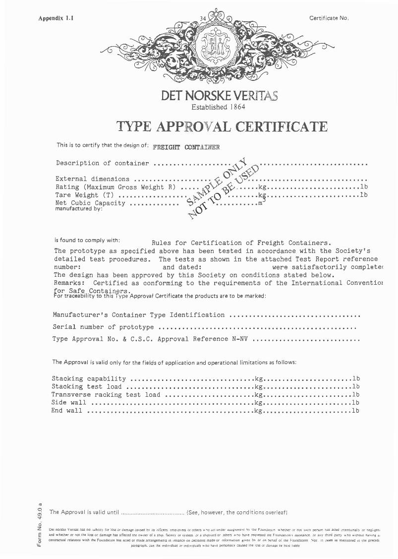
Appendix 1.1 Certificate No.
DEI NORSKE VERITASEstablished 1864
TYPE APP OVAL CERTIFICATE
is found to comply with:
• 11 ••••••• " " " " " " " " " " " " " " " " " " " " " " " " " " " " " " " " " " " " " " " " " "
This is to certify that the design of: FREIGHT CONTAINER
Description of container .•••••.•.•.••••...•~\-J~ :\) .
External dimensions ••....•.•...•....•.• ~0 -0S~ .Rating (Maximum Gross Weight R) •..• :~~\; ~~_ •.•.. kg .•.•.•....•.••.......•.. lbTare Weight (T) .•....••....•.•••. ~r~o k§ ...........••.•..••..••. lbNet Cubic Capaci ty ••••••••••••• SA' mmanufactured by: ~C~
Rules for Certification of Freight Containers.The prototype as specified above has been tested in accordance with the Society'sdetailed test procedures. The tests as shown in the attached Test Report referencenumber: and dated: were satisfactorily completecThe design has been approved by this Society on conditions stated below.Remarks: Certified as conforming to the requirements of the International Conventio!for Safe Containers.For traceability to this Type Approval Certificate the products are to be marked:
Manufacturer's Container Type Identification ...••.........•...•.....•.••.••.••
Serial number of prototype
Type Approval No. & C.S.C. Approval Reference N-NV ...•....•......••.••....••..
The Approval is valid only for the fields of application and operational limitations as follows:
Stacking capability •..•••••.••••••••••••••••••••••• kg •••••.•••.••••••••••••• lbStacking test load •...•.••.••••••••.•••.•..•••.•••. kg •••...•..••••..••.. o ••• lbTransverse racking test load ••.•................... kg ••..•....•.......•.•... lbSide wall •• 11 11 •• "".11 11 11 11 11 11 11 11 11 11 11 11 11 11 11 11 11 11 11 11 11 11 11 11" 11 11 11 11 11 11 11 .kg. 11 11"11 11 11 11 11 11 11 11 11 11 11 11 11 11 11 11 11 11 .IbEnd wall "11 11 11 "11 11 11 11" 11 11 11 " 11 11" 11 11 11 11 11 11 11 11. " 11 " 11 11 11 11 11 11 11 11 11 11 11 " 11 .kg. 11 11 11 11" "11."" 11 ••••••••••• Ib
III
oen The Approval is valid until (See, however, the conditions overleaf)'>t
oZ Det nOfSke Verlw has no llolblJII) (Of :OSS uf dam.aac ..:aused toy IL$ ,Jllieers. ::mDI\l)ee:s. 'Jr others "" 1'\0 a.:t under ~lalnmenl .,,, ~h~ F.lunJJuon lAohethcr O( nOt 'iuen pe(~m nas acted IOtent:..:>nall) Of l"l~lIil~en,E ilnd whether or nC){ me loss or damage has illTected [nc owner of a ship. ra':Jllty or system. Clf a shipyard or Jiners Nno have requested (ne F')UnJallOn'.i .lSSISL1.nCe, .>r Jny thUd PArt)' 'I. no WithOut ha"IOj 041
0' conlnctual reJallons wilh the Foundation has acted or made .urangemenLS ,n Ichance I)n ,JC'Clslons made or ,n;ormJuon jlven b... or .>" ~nalf oi me FoundatJon :"ior. tn .:ues ;u mentioned '" me prC'Cedl
u.. paragraph. :;:an the Ind'\lldual or LOdl\llduals "",ho ha... c ;:Jcrsonatly caused tne loss oJf JJmolli:c toe h~ld hablc

Design approval conditionsThe Approval is based on the following documentation:
35 Appendix 1.1 continued
Det norske Veritas is to be kept informed on changes in design, choice of parts or materials. Such changes, dissatisfactoryexperience or amendments of applied Rules, Codes, Regulations or Standards may at any time lead to withdrawal of theType Approval.The Type Approval is valid only when the installation/application of the product is in accordance with the current Rulesof Det norske Veritas, Codes, Regulations, Standards and Manufacturer's Specifications, as applicable.
Product certification conditionsProduction survey arrangement:
Tests to be carried out for each product before installation/application:
Documents, signboards etc. which are to accompany each product/delivery:
Other conditions:
File No.: .
~~9O~.;5~
~V~<9~ Hiilvik, date; .
:tt\0'? Ot\~ .
Principal Surveyor
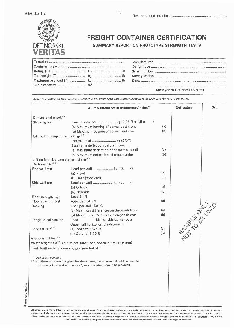
Appendix 1.2
",~~ov..SKE~-P~~ 1$ 0 ~~ ~& 1f~ ~
:..rBlISHt\')~
DETNORSKEVERITAS
36Test report ref. number: .
FREIGHT CONTAINER CERTIFICATIONSUMMARY REPORT ON PROTOTYPE STRENGTH TESTS
Tested at .Container type .Rating (R) kg IbTare weight (T) kg IbMaximum pay load (P) kg IbCubic capacity............................. m3
Manufacturer , .Design type ..Serial number ..Survey station .Date: '
Surveyor to Det norske Veritas
Note: In addition to this Summary Report, a full Prototype Test Report is required in each case for record purposes.
All measurements in millimetres/inches· Deflection Set
Grappler lift test**Weathertightness** (outlet pressure 1 bar, nozzle diam. 12,5 mm)
Tank built under survey and pressure tested**
(a)
(b)
(a)
(b)
(a)
(b)
(a)
(a)(b)
(a)
(b)
(a)
(b)
P)
P)
Load per wall kg. (0,(a) Front(b) Rear (door end)Load per wall kg. (0,(a) Offside(b) NearsideLoad 3 kNAxle load 54 kNLoad per end 150 kN(a) Maximum differences on diagonals front(b) Maximum differences on diagonals rearLoad kN per side/corner postUpper rail horizontal displacement(a) Inner at 0,625 R(b) Outer at 1,25 R
Dimensional check··Stacking test Load per corner kg (0,25 R x 1,8 x
(a) Maximum bowing of corner post front(b) Maximum bowing of corner post rear
Lifting from top corner fittings··Internal load kg (2R·T)Baseframe deflection before lifting(a) Maximum deflection of bottom side rail(b( Maximum deflection of crossmember
Lifting from bottom corner fittings··Restraint test··End wall test
Roof strength testFloor strength testRacking
Side wall test
Longitudinal racking
Fork lift test**
• Delete as necessary•• No dimensions need be given for these items, but a remark should be inserted.
If this remark is "not satisfactory", an explanation should be provided.
'"Ol~
~ozE5u.~ ---' -'-- _
Det norske Ventas has no liability for loss or damage caused by us officers. employees or others who act under assignment by the Foundation. whether or not such person has acted lntentlonall,
negligently and whether or not the loss or damage has affected the owner of a ship. facility or system. or a shipyard or others who have requested the Foundation"s assistance. or any third party.
without having any contractual relations with the Foundation has acted or made arrangements In rehnce on decisions made Of information given by or on behalf of the Foundation. Nor. ,n caSe:
mentioned in the preceding paragraph, can thB individual or IndiV1duals who have personally caused the loss or damage be held liable.

37 Appendix 1.3
Certificate No .
FREIGHT CONTAINER PRODUCTION CERTIFICATE
BASED ON MANUFACTURER'S
QUALITY ASSURANCE SYSTEM
Name and address of manufacturer:
Signature of person responsible
(name also to be typed) .
Survey station: .
Date: .
Surveyor to Det norske Veritas
We hereby certify that the containers specified below have been made according to the Rules of Det norske Veritas andmanufactured under the application of our Quality Assurance System as agreed with Det norske Veritas. Manufacturer's
Quality Assurance System for the Container production is under surveillance of Det norske Veritas. The details of design,
materials and construction conform to the approved plans and to the Prototype Container identified as follows.
Manufacturer's serial number: ..
Tare weight: kg Ib
DnV type approval No. & C.S.C. approval reference: .
Marking:
Manufacturer's Model No: ..
Date of Manufacture: .Type of Container: .
External Dimensions: .Rating: (Maximum gross weight R): kg Ib
Owner's Name & Code Letters: ..
Approval endorsement by Det norske Veritas
Stacking capability: kg IbStacking test load: kg/corner .Transverse racking test load: kg IbEnd wall strength: ..Side wall strength: ..
First examination due date: ..
Number of units covered by this certificate: .
Container Serial NumbersOwner's Manufacturer's
'"<Xlq
~o2§ Remarks: This certificate is valid only when endorsed and signed by the Society's Surveyor.oll.L- -l
Del norske Ventas has no liability 'or loss ()( damage caused by Its orhcers, employees or Olhers who act under aSSignment by the Foundatton, whether or not such person has acted Intentionally or
negligently and whether or nol the ross or damage has affected the owner uf a ShiP, facilHy or syslem or a shipyard or others who have requested the FoundatIOn's assistance. or any thIrd party who
without having any contractual relations with the Foundalton has acted or made arrangements In rehance on deCISions made or Information given by or on behalf of the FoundatIOn. Nor. Ul caSES as
mentioned m the pteCe(hn9 paragraph. can the mdlVldual or mdlvlduals who have personally caused lhe loss or damage be held liable.
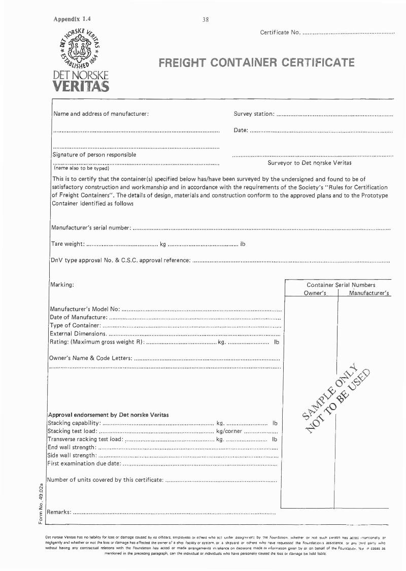
Appendix 1.4
,,~~ov..SKlVt'~?::!i ~o ~-l' {J; If-~ "-J'~ ~
'?blISHt~"
DETNoRSKEVERITAS
Name and address of manufacturer:
Signature of person responsible
38
Certificate No ..
FREIGHT CONTAINER CERTI: ICATE
Survey station: .
Date: .
Surveyor to Det nqrske Veritas·i~·~;.;.;~·~·I·~·t~·b~·ty;;~di····.. ·.. ··· ..· ·· · · ·.. ·· ..
This is to certify that the container(sl specified below has/have been surveyed by the undersigned and found to be ofsatisfactory construction and workmanship and in accordance with the requirements of the Society's "Rules for Certificationof Freight Containers". The details of design, materials and construction conform to the approved plans and to the PrototypeContainer identified as follows
Manufacturer's serial number: .
Tare weight: kg Ib
DnV type approval No. & C.S.C. approval reference: ..
Marking:
Manufacturer's Model No: .Date of Manufacture: ..Type of Container: ..
External Dimensions .Rating: (Maximum gross weight RI: kg. Ib
Owner's Name & Code Letters: ..
Approval endorsement by Det norske Veritas
Stacking capability: kg. IbStacking test load: kg/corner ..Transverse racking test load: , kg IbEnd wall strength: ..Side wa II strength: .First examination due date: ..
Number of units covered by this certificate: .
Container Serial NumbersOwner's Manufacturer's
..NClOl'<t
ozE Remarks: .olJ..L.... _
Det norske Verltas has no liability for losS or damage caused by Its officers, employees or others who act under assignment by the FoundatIon, whether or not SlIch person "as acted Inlt!ntlonally or
negligently and whether or not the loss or damage has affected the owner of a ShIp, faclhty Or system, Or a shipyard or others who have requested the Foundation s assIstance. or an\, third party who
WIthout having any contractual relatIons WIth the FoundatIon has acted or made arrangements In reliance on deCISIons made or information given by Of on behalf of the FOundatIon. Nor ." cases as
menhoned in the preceding paragraph. can the Individual or mdlvtduals who have personally caused the loss or damage be held liable.
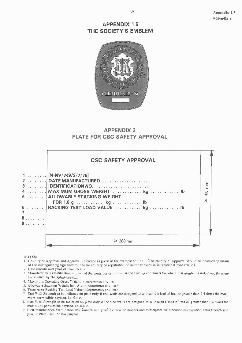
1 .2345
6 .7 .8 .9 .
39
APPENDIX 1.5THE SOCIETY'S EMBLEM
APPENDIX 2PLATE FOR CSC SAFETY APPROVAL
CSC SAFETY APPROVAL
[N-NV/749/2/7/75]DATE MANUFACTURED .IDENTIFICATION NO .MAXIMUM GROSS WEIGHT kg IbALLOWABLE STACKING WEIGHT
FOR 1.8 g kg............ IbRACKING TEST LOAD VALUE kg ., . . . . . . . . .. Ib
> 200 mm-- -
EEoo.....
Appendix 1.5Appendix 2
NOTES:I. Country of Approval and Approval Reference as given in the example on line I. (The country of Approval should be indicated by means
of the distinguishing sign used to indicate country of registration of motor vehicles in international road trafficJ2. Date (month and year) of manufacture.J. Manufacturer's identification number of the container or. in the case of existing containers for which that number is unknown. the num-
ber allotted by the Administration.4. Maximum Operating Gross Weight (kilogrammes and Ibs.l.5. Allowable Stacking Weight for 1.8 g (kilogrammes and lbs.l.6. Transverse Racking Test Load Value (kilogrammes and Ibs.J.7. End Wall Strength to be indicated on plate only if end walls are designed to withstand a load of less or greater than 0.4 times the maxi
mum permissible payload. i.e. 0.4 P.8 Side Wall Strength to be indicated on plate only if the side walls are designed to withstand a load of less or greater than 0,6 times the
maximum permissible payload. i.e. 0.6 P.9. First maintenance examination date (month and year) for new containers and subsequent maintenance examination dates (month and
year) if Plate used for this purpose.

Appendix 3 40
APPENDIX 3EXTERNAL CONTAINER DIMENSIONS, TOLERANCES AND RATINGS
RatingLength (L) Width (\.1\.1 Height (I./J (maximum gross mass)
Freightcontainer mm Tolerances mm Tolerances mm Tolerances kg Ib
designation mm mm mm
IAA 12 192 0 2438 0 2 591· 0 30480 67200-10 -5 -5
lA 12 192 0 24380 2438 0 30480 67200-10 -5 -5
lAX 12192 0 2438 0 < 2438 30480 67200-10 -5
IBB 9 125 0 2438 0 2591· 0 25400 56000-10 -5 -5
18 9 125 0 24380 2438 0
-10 -5 -5 25400 56000
IBX 9 125 0 24380 < 2438 25400 56000-10 -5
ICC 6058 0 2438 0 2591· 0 20320 44800-6 -5 -5
IC 6058 0 24380 2438 0
-6 -5 -5 20320 44800
ICX 6058 0 2438 0 < 2438 20320 44800-6 -5
ID 2991 0 24380 2438 0 10 160 22400
-5 -5 -5
IDX 2991 0 2438 0 < 2 438 10 160 22400-5 -5
• In certain countries there are legal limitations to the overall height of vehicle and load.
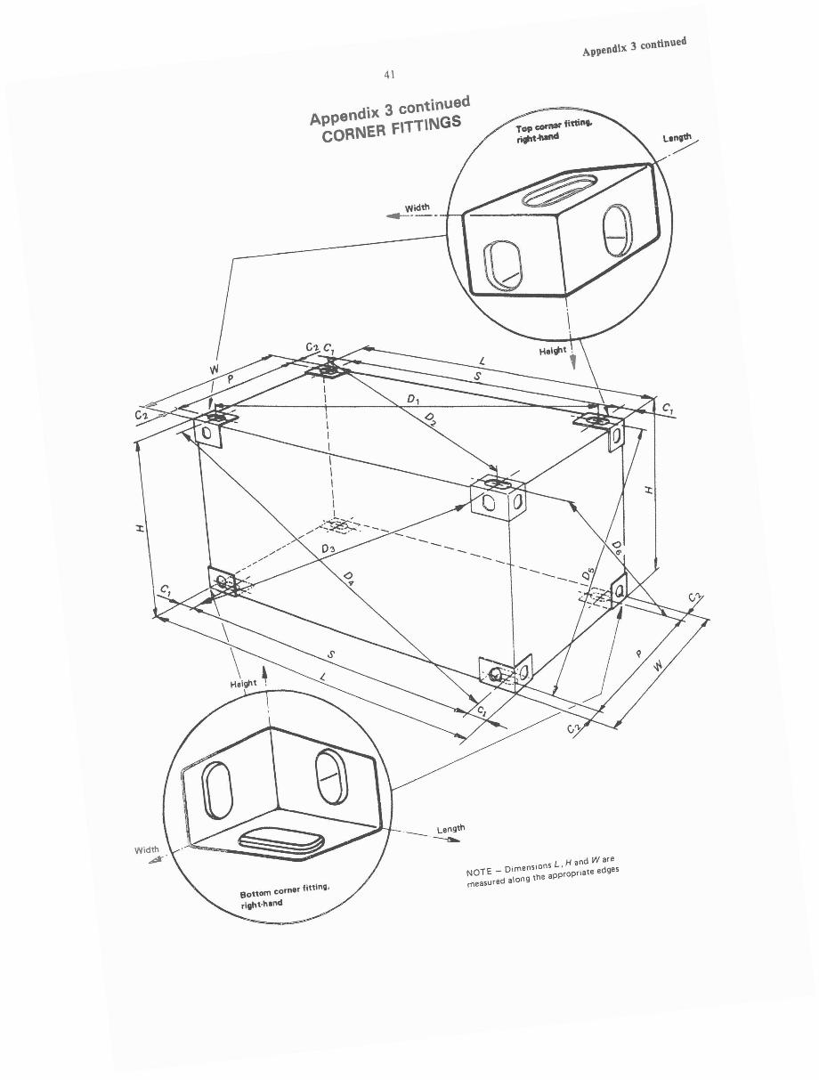
APpendiX 3 continued
4\
_ Length--a.
NOTE _ Dimensions L. Hand Waremeasured along the appropriate edges
L~~..-_------oX'Width
~---,-r----=:::=""'"
APpendix 3 continuedCORNER f\TT\NGS
\
'\Height ~
Width~.
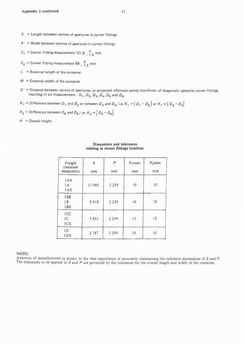
Appendix 3 continued
S = Length between centres of apertures in corner fittings
P = Width between centres of apertures in corner fittings
c, = Cornerfitting measurement 101,5 _ ~ 5 mm
c2 = Corner fitting measurement 89 _ ~ 5 mm
L = External length of the container
W = External width of the container
42
D = Distance between centres of apertures, or projected reference points therefrom, of diagonally opposite corner fittings,resulting in six measurements: D" D2 , D3 , D4 , Ds and D6
K, = Difference between D, and D2 or between D3 and D4 ; i.e. K, = ID, - D2 1 or K, =ID3 - D4 1
K2 = Difference between Os and D6 ; i.e. K2 = IDs - D6 1
H = Overall height
Dimensions and tolerancesrelating to corner fittings locations
Freight S P K, max. K2max.container
designation mm mm mm mm
IAAlA 11 985 2259 19 10lAX
IBBIB 8918 2259 16 10IBX
ICCIC 5853 2259 13 10ICX
ID2787 2259 10 10
IDX
NOTE:Attention of manufacturers is drawn to the vital importance of accurately maintaining the reference dimensions of Sand P.The tolerances to be applied to Sand P are governed by the tolerances for the overall length and width of the container.

43 Appendix 4.1
APPENDIX 4.1TOP CORNER FITTINGDimensions in millimetres
205 0, -1,5 0--
16,0 min. I
20,5 max. 11,0 min. Lt')
0'N
'r ","~ , r,~
~c: I
'E ~J
q ,:-- c:... f 'E... 0x -
i--""~
a;cv vE )'
...Lt') \~ 0-." I ".Y
,
c: ~y~~" .'\~
'E 164,5 min.0CD'... Section B·B
Section A·A
19;0 ± 1,5 III0_-
ILt')
00N
III-0
-f-'-T+----=-..p--::=------lf+----,,-+Lt)
III M-
~====*===~f:-0,- CD.oai00
-~
,JI
I~ "r" 1-
R 14,5 ± 1,5
NOTES
1 Solid and broken lines (- and - -I show surfaces and contours which must be physically duplicated in the fitting.
2 Phantom lines (-----) show optional walls, which may be used to develop a box-shaped fitting.

Appendix 4.2 44
APPENDIX 4.2BOTTOM CORNER FITTING
Dimensions in millimetres
R 14,5 ± 1,5101,5 _ ~,5
tP 124 + 1·,5o
It)
-'0+It)
~.
"_-+--:....-.-__.JJ
- - .... I '/' ....I ~ ...... _.4 _ ~ -.J I. ,I
""_JII
--~,
\ I II II I II I I" I I, - T\..-.L.I
---4
r: r---I J ,
1
'1 II II \
: L -1 1 _
J--
8
,,L __
o101,5_15
+- +--+-+ --r+-'"I I \I I
.L- ~ ~'--"....)
It!,-0+Inai,....
R
51 +1,5o
Section A-A
R 12,5 max.
CEq........ It!,x 0-
"' IE InIn d0' NN
20,5 max. 11 0 ~in .
164,5 min.
c:'Eto
..... "'" - 0LU,O -1,5
NOTESSection 8-B
Solid and broken lines (- and - -) show surfaces and contours which must be physically duplicated in the fitting.
2 Phantom lines (- _. - --) show optional walls, wh ich may be used to develop a box·shaped fitting.
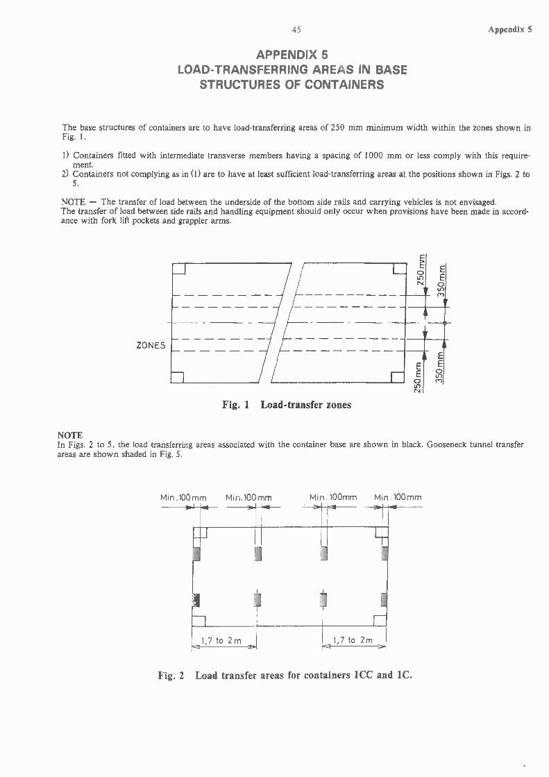
45
APPENDIX 5LOAD-TRANSFERRING AREAS IN BASE
STRUCTURES OF CONTAINERS
Appendix 5
The base structures of containers are to have load-transferring areas of 250 mm minimum width within the zones shown inFig. I.
I) Containers fitted with intermediate transverse members having a spacing of 1000 mm or less comply with this requirement.
2) Containers not complying as in (J) are to have at least sufficient load-transferring areas at the positions shown in Figs. 2 to5.
NOTE - The transfer of load between the underside of the bottom side rails and carrying vehicles is not envisaged.The transfer of load between side rails and handling equipment should only occur when provisions have been made in accordance with fork lift pockets and grappler arms.
ZONES
Fig. I Load-transfer zones
~o10N
EEo10N
EEo10C"')
EE
o10C"')
NOTEIn Figs. 2 to 5, the load transferring areas associated with the container base are shown in black. Gooseneck tunnel transferareas are shown shaded in Fig. 5.
Min.100mm Min.l00mm Min.l00mm Min.l00mm
1,7 to 2 m 1,7 to 2m
Fig. 2 Load transfer areas for containers ICe and IC.

Appendix 5 continued 46
Appendix 5 continued
etMin,lOOmm Min.100mm Min.100mm
Fig. 3 Load transfer areas for containers IBB and IB
Min.1 Omm Min. 100 mmCl
Min.100mm Min.100mm Min.100mm
k-aJ 1,7 to 2 m ~---------JiOIII4IIt----------j
Fig. 4 Load transfer areas for containers IAA and lA without gooseneck tunnels
Min.100mm Min 100mm Min.100mm~
U LI-/ / / /
~ J~
~FOR TUNNEL DETAILS, ISEE APPENDIX 6,3
/ /' j-'
-~ I i I
I !Min. 3156 mm I... 1,7 to 2m'.::::1t,}------_cLt-------~~Fig. 5 Load tr~l1sf~r areas for containers lAA and lA with goosened tunnels
47 Appendix 6.1
APPENDIX 6.1DIMENSIONS OF FORK-LIFT POCKETS
~~~-------,--,---A I
U L
B' I
B I
~J.-V
I I\,J r..J
iCl,
I I I I , cb----, I r-I I ,
I I T L-I v4
IA' -
I
Section y-y Section X-X
Dimensions
Fork pockets for loaded Fork pockets for un-Container and unloaded containers loaded containers only
mm mm
A B C D A' B' C'
lCC 2050 355 115 20 900 305 102le ± 50 min. min. min. ± 50 min. min.
ID900 20
lE305 102
IF± 50 min. min. min.
:'-IOTE; C = Clear opening.
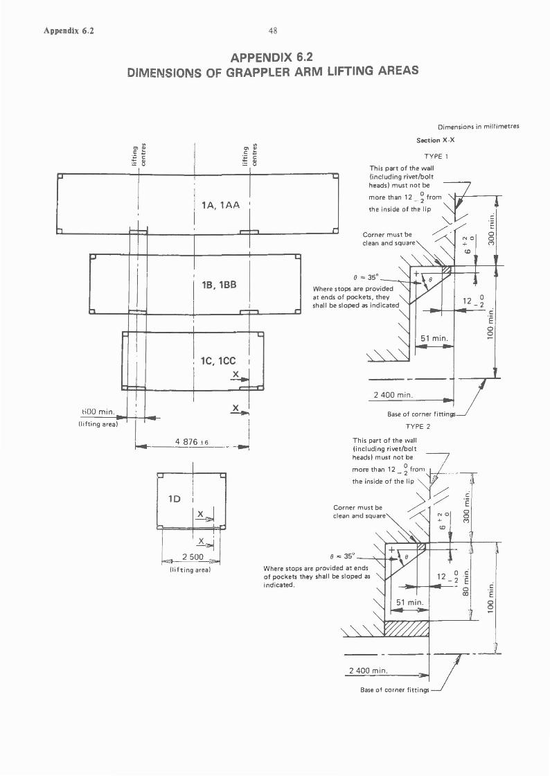
Appendix 6.2 48
APPENDIX 6.2DIMENSIONS OF GRAPPLER ARM LIFTING AREAS
Dimensions in millimetres
c::'EooM
'Eoo
12 0 C-2 E c::
0co 'E
00
12 0-2
~"'-t-ooI'-- c::
51 min.
Section X·X
TYPE 2
Base of corner fittings
2400 min.
TYPE 1
This part of the wall(including rivet/boltheads) must not be
more than 12 _ ~ from
the inside of the lip
Corner must beclean and square
8 '" 35°- ........~,I..."
ops are providedf pockets, theyaped as indicated
This part of the wall(including rivet/bolt
heads) must not beiJmore than 12 _ ~ from
the inside of the lip ",,-'-;::; 'E~'
Corner must be /..clean and square -' NOg
M
8 '" 35° _--->.,...-+....'\.
Where stops are provided at endsof pockets they shall be sloped asindicated.
(lifting area)
~ 1:
1D I
~!
L~
- 2500 ..
k--__4--::.876 ± 6
'" onCl Ql Cl QlC ... C ~.- ...... c .~ c:: fl - ..:.: (J
~ L.
I
IlA,lAA I
:-t I-I- r--f--t,..
~ L:I
I ,
I18,18B Where st
at ends 0
h ~- ...-'...... r'"shall be si
I
L.
I
11C, 1CC I
~I---T
I X ItiOO min. -...(lifting area) I -
I
Base of corner fittings
- 7--2400 min.

49
APPENDIX 6.3DIMENSIONS OF GOOSENECK TUNNELS
Face of front crossmember
A~
D
NOTE - The 8 t tolerance should be measured in the rear part ofthe tunnel, on a length of about 600 mm
Level of transverse members
View A
----+----I
---~-----
Symbols Dimensionsmm
Lt 3 150 min.Length
+ ID 6 _ 2
At I 029+3
Width0
Bt 1200
-3
Height+5
C 12.5 _ I.5
Appendix 6.3
o

![DNVGL-RP-0043 Safety, operation and performance …rules.dnvgl.com/docs/pdf/DNVGL/RP/2017-09/DNVGL-RP-0043.pdfFor safety considerations regarding second life systems, see [7.5.1.7].](https://static.fdocuments.in/doc/165x107/5f9e7843ea8263465129a2ef/dnvgl-rp-0043-safety-operation-and-performance-rulesdnvglcomdocspdfdnvglrp2017-09dnvgl-rp-0043pdf.jpg)