RULES FOR THE CLASSIFICATION OF NAVAL SHIPS · · 2014-12-25RULES FOR THE CLASSIFICATION OF NAVAL...
112
RULES FOR THE CLASSIFICATION OF NAVAL SHIPS PROPULSION PLANTS Part E Chapter 104 - Propulsion Plants 2007
Transcript of RULES FOR THE CLASSIFICATION OF NAVAL SHIPS · · 2014-12-25RULES FOR THE CLASSIFICATION OF NAVAL...
RULES FOR THE CLASSIFICATION
OF NAVAL SHIPS
PROPULSION PLANTS
Part E
Chapter 104 - Propulsion Plants
2007

TÜRK LOYDU HEAD OFFICE
Postane Mah. Tersaneler Cad. No:26 Tuzla 34944 İSTANBUL / TÜRKİYE Tel : (90-216) 446 22 40 (6 hat) Fax : (90-216) 446 22 46 - 446 19 14 - 395 49 95 E-mail : [email protected] http://www.turkloydu.org
BRANCH OFFICES Ankara Atatürk Bulvarı Sefaretler Apt. 199/B D:1 Kavaklıdere 06680 Tandoğan-ANKARA
Tel : (90-312) 468 10 46 Fax : (90-312) 427 49 42 E-mail : [email protected]
İzmir Atatürk Cad. No :378 K.4 D.402 35220 Kavalalılar Apt. Alsancak - İZMİR
Tel : (90-232) 464 29 88 Fax : (90-232) 464 87 51
E-mail : [email protected]
Table of Contents Section 1 General Rules and Instructions
A. General ................................................................................................................................................................. 1- 1
B. Definitions ............................................................................................................................................................. 1- 2
C. Documents for Approval ....................................................................................................................................... 1- 4
D. Ambient Conditions ............................................................................................................................................... 1- 5
E. Materials ............................................................................................................................................................... 1- 11
F. Fuels and Consumables for Operation ................................................................................................................. 1- 12
G. Safety Equipment and Protective Measures ......................................................................................................... 1- 13
H. Survivability ........................................................................................................................................................... 1- 13
Section 2 Design and Construction of the Machinery Installation
A. General ................................................................................................................................................................. 2- 1
B. Dimensions of Components .................................................................................................................................. 2- 1
C. Availability of Machinery ....................................................................................................................................... 2- 2
D. Control and Regulating ......................................................................................................................................... 2- 3
E. Propulsion Plant .................................................................................................................................................... 2- 3
F. Turning Appliances ............................................................................................................................................... 2- 4
G. Operating and Maintenance Instructions .............................................................................................................. 2- 4
H. Markings, Identification ......................................................................................................................................... 2- 4
I. Engine Room Equipment ...................................................................................................................................... 2- 6
J. Communication and Signalling Equipment ........................................................................................................... 2- 7
K. Redundant Systems .............................................................................................................................................. 2- 7
Section 3 Internal Combustion Engines
A. General ................................................................................................................................................................. 3- 1
B. Documents for Approval ....................................................................................................................................... 3- 2 C. Crankshaft Design ................................................................................................................................................ 3- 4
D. Materials ............................................................................................................................................................... 3- 5
E. Tests and Trials .................................................................................................................................................... 3- 7
F. Safety Devices ...................................................................................................................................................... 3- 13
G. Auxiliary Systems .................................................................................................................................................. 3- 17
H. Control Equipment ................................................................................................................................................ 3- 20
I. Alarms ................................................................................................................................................................... 3- 21
J. Engine Alignment/Seating ..................................................................................................................................... 3- 21
Section 4 Thermal Turbomachinery
A. General ................................................................................................................................................................. 4- 1
B. Materials ............................................................................................................................................................... 4- 1

C. Design and Construction Principles ...................................................................................................................... 4- 2
D. Emergency Operation ........................................................................................................................................... 4- 5
E. Control and Safety Equipment .............................................................................................................................. 4- 5
F. Monitoring Equipment ........................................................................................................................................... 4- 6
G. Maintenance ......................................................................................................................................................... 4- 7
H. Tests ................................................................................................................................................................... 4- 7
I. Trials ................................................................................................................................................................... 4- 8
Section 5 Main Shafting
A. General ................................................................................................................................................................. 5- 1
B. Materials ............................................................................................................................................................... 5- 1
C. Shaft Dimensions .................................................................................................................................................. 5- 2
D. Design ................................................................................................................................................................... 5- 4
E. Pressure Tests ...................................................................................................................................................... 5- 9
F. Special Requirements for Fibre Laminate Shafts .................................................................................................. 5- 9
Section 6 Gears, Couplings
A. General ................................................................................................................................................................. 6- 1
B. Materials ............................................................................................................................................................... 6- 1
C. Calculation of the Load-Bearing Capacity of Gear Theeth .................................................................................... 6- 2
D. Gear Shafts ........................................................................................................................................................... 6- 8
E. Equipment ............................................................................................................................................................. 6- 8
F. Balancing and Testing .......................................................................................................................................... 6- 9
G. Design and Construction of Couplings .................................................................................................................. 6- 10
Section 7 Propeller
A. General ................................................................................................................................................................. 7- 1 B. Materials ............................................................................................................................................................... 7- 1
C. Design and Dimensioning of Propellers ................................................................................................................ 7- 2
D. Propeller Mounting ................................................................................................................................................ 7- 7
E. Controllable Pitch Propellers ................................................................................................................................. 7- 8
F. Balancing and Testing .......................................................................................................................................... 7- 10
G. Rudder Propeller Units .......................................................................................................................................... 7- 11
H. Lateral Thrust Units ............................................................................................................................................... 7- 13
I. Water Jet Propulsion Systems .............................................................................................................................. 7- 14
J. Special Forms of Propulsion Systems .................................................................................................................. 7- 15
K. Dynamic Positioning Systems (DP Systems) ........................................................................................................ 7- 16
L. Cavitation Noise of Propellers ............................................................................................................................... 7- 18

Section 8 Torsional Vibrations
A. General ................................................................................................................................................................. 8- 1
B. Calculation of Torsional Vibrations ........................................................................................................................ 8- 1
C. Permissible Torsional Vibration Stresses .............................................................................................................. 8- 2
D. Torsional Vibration Measurements ....................................................................................................................... 8- 6
E. Prohibited Ranges of Operation ............................................................................................................................ 8- 6
F. Auxiliary Machinery ............................................................................................................................................... 8- 6
Section 9 Machinery for Ships with Ice Classes
A. General ................................................................................................................................................................. 9- 1
B. Requirements for Notation E ................................................................................................................................. 9- 1
Section 10 Spare Parts
A. General ................................................................................................................................................................. 10- 1
B. Volume of Spare Parts .......................................................................................................................................... 10- 1

Section 1– General Rules and Instructions 1-1
SECTION 1
GENERAL RULES AND INSTRUCTIONS A. General 1. These Rules apply to the propulsion plant of
seagoing surface ships and craft intended for naval
activities.
The following types of propulsion plants are not in-
cluded in these Rules:
- Nuclear power plants
- Plants with fuel cell technology (1)
- Steam boilers for main propulsion
- Steam turbines
- Low speed diesel engines with crossheads
- Reversible two-stroke diesel engines
- Plants for operation with heavy fuel oil and its
pretreatment
However, on application, plants of a type listed above
may be included in a design review and classification
procedure, where relevant for the overall concept of a
naval project.
2. Apart from machinery and equipment
detailed below, these Rules are also applicable
individually to other machinery and equipment where
this is necessary for the safety of the ship and its crew.
3. Designs which deviate from these Rules may
be approved, provided that such designs have been
recognized as equivalent.
4. Machinery installations which have been
developed on novel principles and/or which have not
yet been sufficiently tested in shipboard service
require special TL approval.
In such cases TL is entitled to require additional
documentation to be submitted and special trials to be
carried out. Such machinery may be marked by the
Notation EXP affixed to the Character of Classification.
5. In addition to these Rules, TL reserve the
right to impose further requirements in respect of all
types of machinery where this is unavoidable due to
new findings or operational experience, or TL may
permit deviations from the Rules where these are
specially warranted.
6. Reference to further regulations and standards
6.1 If the requirements for propulsion plants and
operating agents are not defined in these Rules, the
application of other regulations and standards has to
be defined as far as necessary. 6.2 The regulations of the "International
Convention for the Safety of Life at Sea
1974/1978" (SOLAS), as amended are considered in
these Rules as far as they appear to be applicable to
naval surface combat ships. The definite scope of
application has to be defined in the building
specification by the Naval Authority and the shipyard.
These Rules are also in compliance with the provisions
of the "International Convention for the Prevention of
Pollution from Ships" of 1973 and the relevant Protocol
of 1978 (MARPOL 73/78).
(1) For auxiliary power to be produced with fuel cell
technology see TL Rules Guidelines for the Use of Fuel Cell
Systems on Board of Ships and Boats.
1-2 Section 1 – General Rules and Instructions 6.3 For ships of NATO states the Nato
Agreement for Standardisation (STANAG) has to be
considered. 6.4 Besides of these Rules national regulations,
international standards and special definitions in the
building specification respectively in the mission
statement of the actual ship have to be considered. The
application of such regulations is not affected by the
TL Rules.
7. Design
The design of the propulsion plant has to fulfill the
following conditions:
7.1 The operation of the naval ship and the
habitual conditions foreseen on board as well as the
operation of all systems under the operational
conditions of combat, wartime cruise, peacetime cruise
and peacetime in-port readiness must be ensured at all
times.
7.2 The power distribution network shall be
designed to ensure operability in case of network failure. 7.3 The operation of certain systems and
equipment, which are necessary for safety, is to be
guaranteed under defined emergency conditions.
7.4 The risks for crew and ship from operation of
the propulsion plant shall be minimized.
7.5 High working reliability shall be achieved by
simple and clearly arranged operation processes as
well as by application of type-approved products.
7.6 The requirements concerning design, ar-
rangement, installation and operation which are de-
fined in Chapter 101 - Classification and Surveys and
Chapters 102 - Hull Structures and Ship
Equipment , 105 - Electrical Installations, 106 -
Automation and 107 – Ship Operation Installations
and Auxiliary Systems, must be fulfilled.
7.7 A high degree of survivability of the ship
should be achieved by redundancies in the design and
functioning of essential equipment.
7.8 The principles of ergonomic design of
machinery and equipment have to be considered.
7.9 Where in a class of naval ships, originally
planned to be identical, deviations become necessary,
TL shall be duly informed and changes properly
documented.
B. Definitions
1. Ship speeds
1.1 v0
Expected maximum, continuous ahead speed v0 [kn] of
the ship in calm water at the draught T, when the total
available driving power is acting exclusively on the
propulsion devices.
1.2 vmax
Expected maximum ahead speed vmax [kn] of the ship in
calm water at the draught T, when the total available
maximum driving power is acting exclusively on the
propulsion devices. This speed is related to an
overload condition, permissible only for a defined,
relatively short time period.
1.3 vM
Expected economic, continuous ahead cruising speed
vM [kn] of the ship, which provides the maximum radius
of action.
1.4 vmin
Expected minimum ahead speed vmin [kn] of the ship in
calm water at the draught T, when the total available
driving power is acting at its technically possible
minimum power output.
1.5 Draught T
The draught T is the vertical distance at the middle of
the length L, from base line to the deepest design
water line, as estimated for the lifetime of the ship.

Section 1– General Rules and Instructions 1-3 2. Rated driving power P
The rated driving power [kW] is defined as continuous
power to be delivered by the propulsion machinery
when running at rated speed and with the total available
power acting exclusively on the propulsion devices.
3. Auxiliary electrical power
The auxiliary electrical power [kVA] is defined as the
continuous electrical power at continuous speed v0,
which is not directly used for propulsion of the ship, but
for driving all kinds of auxiliary devices and equipment.
The degree of redundancy shall be defined in the
building specification.
4. Essential equipment 4.1 Principal requirements
Essential equipment is required to ensure continuity of
the following functions:
- Propulsion, manoeuvrability, navigation and
safety of the ship
- Safety of the crew and embarked troops
- Functioning of all equipment, machinery and
appliances needed for flooding control, fire
fighting, NBC defence, degaussing, etc.
- Functioning of all equipment, machinery and
appliances needed to an unrestricted extent
for the primary duty of the naval ship
These requirements apply for the mechanical part of
the equipment and complete equipment units supplied
by subcontractors.
Essential equipment is subdivided into:
- Primary essential equipment according to 4.2
- Secondary essential equipment according to 4.3
4.2 Primary essential equipment
Primary essential equipment is that required to be
operative at all times to maintain the manoeuvrability of
the ship as regards propulsion and steering and that
required directly for the primary duty of the naval ship.
It comprises e.g.:
- Steering gear
- Controllable pitch-propeller installation
- Scavenging air blowers, fuel oil supply pumps,
fuel booster pumps, fuel valve cooling pumps,
lubricating oil pumps, cooling water pumps for
main and auxiliary engines and turbines
necessary for propulsion
- Forced draught fans, feed water pumps, water
circulating pumps, vacuum pumps and
condensate pumps for auxiliary boilers of ships
where steam is used for equipment supplying
primary essential equipment
- Burner equipment for auxiliary steam boilers of
ships where steam is used for equipment
supplying primary essential equipment
- Azimuth thrusters which are the sole means
for propulsion/steering including lubricating oil
pumps, cooling water pumps
- Main propulsion plant with internal combustion
engines and gas turbines, gears, main
shafting, propellers
- Electric generator units and associated power
sources supplying primary essential equipment
- Hydraulic pumps for primary essential equip-
ment
- Weapon systems (effectors)
4.3 Secondary essential equipment
Secondary essential equipment is that required for the
safety of ship and crew, and is such equipment which can
briefly be taken out of service without the propulsion,
steering and equipment needed for the primary duty of
the naval ship, being unacceptably impaired.

1-4 Section 1 – General Rules and Instructions It comprises e.g.:
- Windlasses and capstans
- Azimuth thrusters, if they are auxiliary equipment
- Fuel oil transfer pumps and fuel oil treatment
equipment
- Lubrication oil transfer pumps and lubrication oil
treatment equipment
- Starting air and control air compressors
- Turning device for main engines
- Bilge, ballast and heel-compensating installations
- Fire pumps and other fire fighting installations
- Ventilating fans for engine and boiler rooms
- Equipment considered necessary to maintain
endangered spaces in a safe condition
- Equipment for watertight closing appliances
- Auxiliary and main engine starting installations
- Generator units supplying secondary essential
equipment, if this equipment is not supplied by
generators as described in 4.2
- Hydraulic pumps for secondary essential
equipment
- Parts of the shipboard aircraft installations
- NBC fans and passage heaters
- Decontamination equipment
5. Non-essential equipment
Non-essential equipment is that which temporary
disconnection does not impair the principal
requirements defined in 4.1.
C. Documents for Approval
1. All documents have to be submitted for
approval to TL in Turkish or English language. 2. The survey of the ship's construction will be
carried out on the basis of approved documents. The
drawings must contain all data necessary for approval.
Where necessary, calculations and descriptions of the
ship's elements are to be submitted. Any non-standard
symbols used are to be explained in a key list. All
documents have to indicate the number of the project
and the name of the Naval Authority and/or shipyard.
The drawings and documents have to give sufficient
evidence for proving that the requirements set out in
this Chapter have been complied with.
3. The supporting calculations shall contain all
necessary information concerning reference
documents. Literature used for the calculations has to
be cited, important but not commonly known
sources shall be added in copy.
The choice of computer programs according to the
"State of the Art" is free. The programs may be
checked by TL through comparative calculations with
predefined test examples. A generally valid approval for
a computer program is, however, not given by TL.
The calculations have to be compiled in a way which
allows to identify and check all steps of the calculation in
an easy way. Hand written, easily readable documents
are acceptable.
Comprehensive quantities of output data shall be pre-
sented in graphic form. A written comment to the
main conclusions resulting from the calculations has to
be provided.
4. A summary of the required documents is
contained in Chapter 101 - Classification and
Surveys, Table 4.1. Further details are defined in the
following Sections of this Chapter.
5. TL reserve the right to demand additional
documentation if that submitted is insufficient for an
assessment of the naval ship.

Section 1– General Rules and Instructions 1-5 This may especially be the case for plants and
equipment related to new developments and/or which
are not tested on board to a sufficient extent.
6. The drawings are to be submitted in
triplicate, all calculations and supporting documentation
in one copy for examination at a sufficiently early date to
ensure that they are approved and available to the
Surveyor at the beginning of the manufacture of or
installation on the naval ship.
7. Once the documents submitted have been
approved by TL they are binding for the execution of
the work. Subsequent modifications and extensions
require the approval of TL before being put into effect.
8. At the commissioning of the naval ship or
after considerable changes or extensions of the propul-
sion plant, the documentation for approval as defined in
the different Sections, showing the final condition of the
systems, has to be given on board. All documents have
to indicate the name of the ship, the newbuilding
number of the shipyard and the date of execution.
D. Ambient Conditions
1. General operating conditions
1.1 The selection, layout and arrangement of
the ship's structure and all shipboard machinery shall
be such as to ensure faultless continuous operation
under defined standard ambient conditions.
More stringent requirements must be observed for
Class Notation AC1 (see Chapter 101 - Classification
and Surveys, Section 2, C.).
For the Class Notation ACS variable requirements for
unusual types and/or tasks of naval ships can be
discussed case by case, but shall not be less than the
standard requirements.
Components in the machinery spaces or in other
spaces which comply with the conditions for the
Notations AC1 or ACS must be approved by TL.
1.2 Inclinations and movements of the ship
The design conditions for static and dynamic
inclinations of a naval ship have to be assumed
independently from each other. The standard
requirements and the requirements for Class Notation
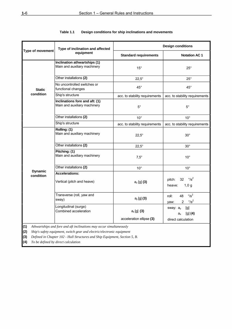
AC1 are defined in Table 1.1.
The effects of elastic deformation of the ship's hull on the
machinery installation have to be considered.
1.3 Environmental conditions
The standard requirements and the requirements for
Class Notation AC 1 are defined in Table 1.2.
2. Vibrations
2.1 General 2.1.1 Machinery, equipment and hull structures are
normally subject to vibration stresses. Design,
construction and installation must in every case take
account of these stresses.
The fault-free long-term service of individual components
shall not be endangered by vibration stresses.
2.1.2 Where a machine or a piece of equipment
generates vibrations when in operation, the intensity
of the vibration shall not exceed defined limits. The
purpose is to protect the vibration generators, the
connected assemblies, peripheral equipment and hull
components from additional, excessive vibration
stresses liable to cause premature failures or
malfunctions.
2.1.3 The following provisions relate to vibrations in
the frequency range from 2 to 300 Hz. The underlying
assumption is that vibrations with oscillation
frequencies below 2 Hz can be regarded as rigid-
body vibrations while vibrations with oscillation
frequentcies above 300 Hz normally occur only
locally and may be interpreted as structure-borne
noise. Where, in special cases, these assumptions
are not valid (e.g. where the vibration is generated by
a gear pump with a tooth meshing frequency in the
range above 300 Hz) the following provisions are to
be applied in analogous manner.
1-6 Section 1 – General Rules and Instructions
Table 1.1 Design conditions for ship inclinations and movements
Type of movement Type of inclination and affected equipment
Design conditions
Standard requirements Notation AC 1
Static condition
Inclination athwartships (1) Main and auxiliary machinery 15° 25°
Other installations (2) 22,5° 25°
No uncontrolled switches or functional changes 45° 45°
Ship's structure acc. to stability requirements acc. to stability requirements
Inclinations fore and aft: (1) Main and auxiliary machinery 5° 5°
Other installations (2) 10° 10°
Ship's structure acc. to stability requirements acc. to stability requirements
Dynamic condition
Rolling: (1) Main and auxiliary machinery 22,5° 30°
Other installations (2) 22,5° 30°
Pitching: (1) Main and auxiliary machinery 7,5° 10°
Other installations (2) 10° 10°
Accelerations: Vertical (pitch and heave) az [g] (3) pitch: 32 °/s2
heave: 1,0 g
Transverse (roll, yaw and sway) ay [g] (3) roll: 48 °/s2
yaw: 2 °/s2 Longitudinal (surge) Combined acceleration ax [g] (3)
acceleration ellipse (3)
sway: ay [g]
ax [g] (4)
direct calculation
(1) Athwartships and fore and aft inclinations may occur simultaneously
(2) Ship's safety equipment, switch gear and electric/electronic equipment
(3) Defined in Chapter 102 - Hull Structures and Ship Equipment, Section 5, B.
(4) To be defined by direct calculation
Section 1– General Rules and Instructions 1-7
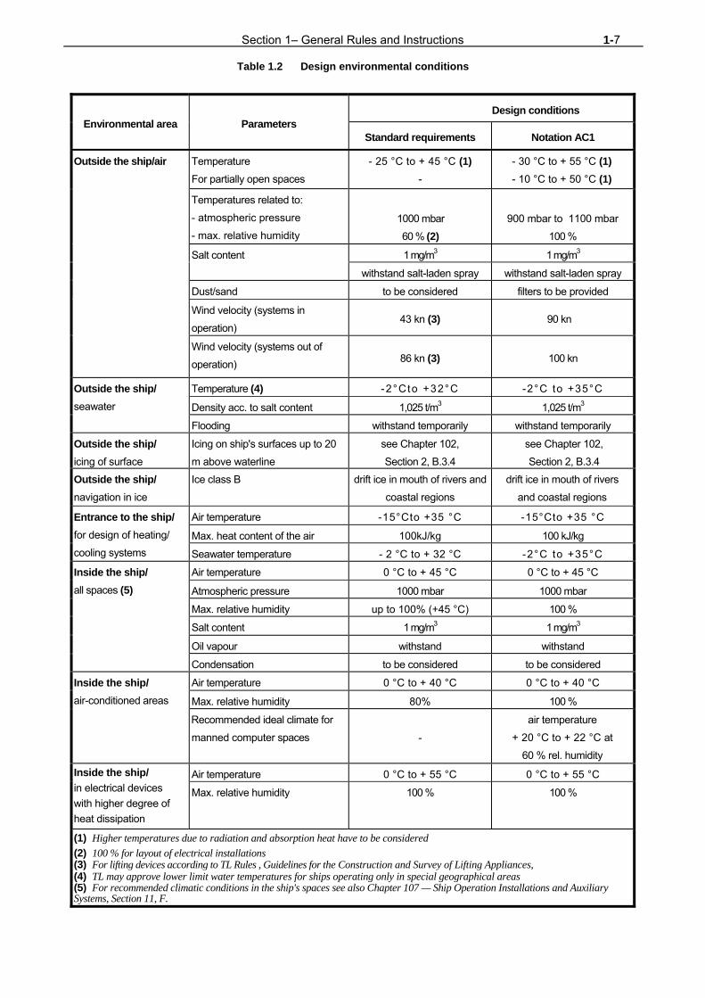
Table 1.2 Design environmental conditions
Environmental area Parameters Design conditions
Standard requirements Notation AC1
Outside the ship/air
Temperature
For partially open spaces
- 25 °C to + 45 °C (1) -
- 30 °C to + 55 °C (1) - 10 °C to + 50 °C (1)
Temperatures related to:
- atmospheric pressure
- max. relative humidity
1000 mbar
60 % (2) 900 mbar to 1100 mbar
100 %
Salt content 1 mg/m3 1 mg/m3
withstand salt-laden spray withstand salt-laden spray
Dust/sand to be considered filters to be provided
Wind velocity (systems in
operation) 43 kn (3) 90 kn
Wind velocity (systems out of
operation) 86 kn (3) 100 kn
Outside the ship/ seawater
Temperature (4) -2°Cto +32°C -2°C to +35°C
Density acc. to salt content 1,025 t/m3 1,025 t/m3
Flooding withstand temporarily withstand temporarily
Outside the ship/ icing of surface
Icing on ship's surfaces up to 20
m above waterline
see Chapter 102,
Section 2, B.3.4
see Chapter 102,
Section 2, B.3.4
Outside the ship/ navigation in ice
Ice class B drift ice in mouth of rivers and
coastal regions
drift ice in mouth of rivers
and coastal regions
Entrance to the ship/ for design of heating/
cooling systems
Air temperature -15°Cto +35 °C -15°Cto +35 °C
Max. heat content of the air 100kJ/kg 100 kJ/kg
Seawater temperature - 2 °C to + 32 °C -2°C to +35°C
Inside the ship/ all spaces (5)
Air temperature 0 °C to + 45 °C 0 °C to + 45 °C
Atmospheric pressure 1000 mbar 1000 mbar
Max. relative humidity up to 100% (+45 °C) 100 %
Salt content 1 mg/m3 1 mg/m3
Oil vapour withstand withstand
Condensation to be considered to be considered
Inside the ship/ air-conditioned areas
Air temperature 0 °C to + 40 °C 0 °C to + 40 °C
Max. relative humidity 80% 100 %
Recommended ideal climate for
manned computer spaces -
air temperature
+ 20 °C to + 22 °C at
60 % rel. humidity
Inside the ship/ in electrical devices
with higher degree of
heat dissipation
Air temperature 0 °C to + 55 °C 0 °C to + 55 °C
Max. relative humidity 100 % 100 %
(1) Higher temperatures due to radiation and absorption heat have to be considered
(2) 100 % for layout of electrical installations (3) For lifting devices according to TL Rules , Guidelines for the Construction and Survey of Lifting Appliances, (4) TL may approve lower limit water temperatures for ships operating only in special geographical areas (5) For recommended climatic conditions in the ship's spaces see also Chapter 107 — Ship Operation Installations and Auxiliary Systems, Section 11, F.

1-8 Section 1 – General Rules and Instructions 2.1.4 Attention has to be paid to vibration stresses
over the whole relevant operating range of the
vibration exciter.
Where the vibration is generated by an engine,
consideration must cover the whole available working
speed range and, where appropriate, to the whole
power range.
2.1.5 The procedure described below is largely
standardized. Basically, a substitution quantity is
formed for the vibration stress or the intensity of the
exciter spectrum (cf. 2.2.1). This quantity is then
compared with permissible or guaranteed values to
check that it is admissible. 2.1.6 The procedure mentioned in 2.1.5 takes the
physical facts into account only incompletely. The aim is
to evaluate the true alternating stresses or alternating
forces. No simple relationship exists between the
actual load and the substitution quantities: vibration
amplitude, vibration velocity and vibration acceleration
at the external parts of the frame. Nevertheless, this
procedure is adopted since at present, it appears to be
the only one which can be implemented in a
reasonable way. For these reasons it is expressly
pointed out that the magnitude of the substitution
quantities applied in relation to the relevant limits
enables no conclusion to be drawn concerning the
reliability or load of components as far as these limits
are not exceeded. It is, in particular, inadmissible to
compare the load of components of different
reciprocating machines by comparing the substitution
quantities measured at the engine frame. 2.1.7 For reciprocating machinery, the following
statements are only applicable for outputs over
100 kW and speeds below 3 000 min-1. 2.1.8 The special rules concerning torsional
vibrations according to Section 8 have to be considered. 2.2 Assessment 2.2.1 In assessing the vibration stresses imposed
on machinery, equipment and hull structures, the
vibration velocity v is generally used as a criterion for
the prevailing vibration stress. The same criterion is
used to evaluate the intensity of the vibration spectrum
produced by a vibration exciter (cf. 2.1.2).
In the case of a purely sinusoidal oscillation, the effective
value of the vibration velocity veff can be calculated by
the formula:
(1)
in which
s = vibration displacement amplitude,
v = vibration velocity amplitude,
veff = effective value of vibration velocity,
â = vibration acceleration amplitude,
ω = angular velocity of vibration.
For any periodic oscillation with individual harmonic
components 1,2,...n, the effective value of the vibration
velocity can be calculated by the formula:
v + ... + v + v = v 2effneff2
2eff1effi
2 (2)
in which veff is the effective value of the vibration
velocity of the i-th harmonic component. Using formula
(1), the individual values of veffi are to be calculated for
each harmonic.
Depending on the prevailing conditions, the effective
value of the vibration velocity is given by formula (1) for
purely sinusoidal oscillations or by formula (2) for any
periodic oscillation.
2.2.2 The assessment of vibration loads is gener-
ally based on areas A, B and C, which are enclosed by
the boundary curves shown in Fig. 1.1. The boundary
curves of areas A, B, and C are indicated in Table 1.3. If
the vibration to be assessed comprises several
harmonic components, the effective value according
to 2.2.1 must be applied. The assessment of this
value shall take account of all important harmonic
components in the range from 2 to 300 Hz.
ω
a
2
1 = v
2
1 = ω s
2
1 = veff
Section 1– General Rules and Instructions 1-9
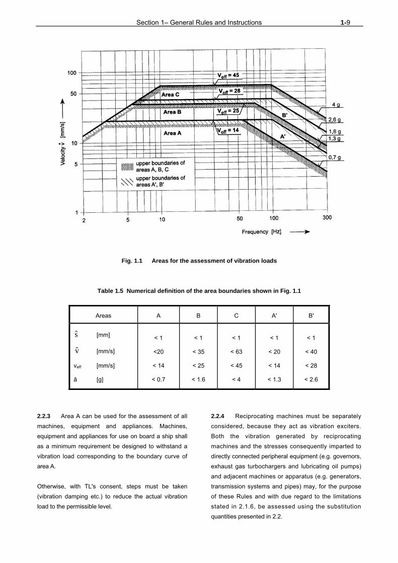
Fig. 1.1 Areas for the assessment of vibration loads
Table 1.5 Numerical definition of the area boundaries shown in Fig. 1.1
Areas
A B C A'
B'
s [mm]
v [mm/s] veff [mm/s] â [g]
< 1
<20
< 14
< 0.7
< 1
< 35
< 25
< 1.6
< 1
< 63
< 45
< 4
< 1
< 20
< 14
< 1.3
< 1
< 40
< 28
< 2.6
2.2.3 Area A can be used for the assessment of all
machines, equipment and appliances. Machines,
equipment and appliances for use on board a ship shall
as a minimum requirement be designed to withstand a
vibration load corresponding to the boundary curve of
area A. Otherwise, with TL's consent, steps must be taken
(vibration damping etc.) to reduce the actual vibration
load to the permissible level.
2.2.4 Reciprocating machines must be separately
considered, because they act as vibration exciters.
Both the vibration generated by reciprocating
machines and the stresses consequently imparted to
directly connected peripheral equipment (e.g. governors,
exhaust gas turbochargers and lubricating oil pumps)
and adjacent machines or apparatus (e.g. generators,
transmission systems and pipes) may, for the purpose
of these Rules and with due regard to the limitations
stated in 2.1.6, be assessed using the substitution
quantities presented in 2.2.
1-10 Section 1 – General Rules and Instructions 2.2.4.1 In every case the manufacturer of reciprocating
machines has to guarantee permissible vibration loads
for the important directly connected peripheral
equipment. The manufacturer of the reciprocating
machine is responsible to TL for proving that the
vibration loads are within the permissible limits in
accordance with 2.3.
2.2.4.2 Where the vibration loads of reciprocating
machines lie within the A' area, separate consideration
or verifications relating to the directly connected
peripheral equipment (cf. 2.2.4) are not required. The
same applies to machines and apparatus located in
close proximity to the vibration exciter (2.2.4).
In these circumstances directly connected peripheral
appliances shall in every case be designed for at least
the limit loads of area B', and machines located nearby
for the limit loads of area B.
If the permissible vibration loads of individual directly
connected peripheral appliances in accordance with
2.2.4.1 lie below the boundary curve of area B,
permissibility must be proved by measurement of the
actually occurring vibration load.
2.2.4.3 If the vibration loads of reciprocating machines
lie outside area A' but are still within area B', it must be
proved by measurement that directly connected
peripheral appliances are not loaded above the limits for
area C.
In these circumstances directly connected peripheral
appliances shall in every case be designed for at least
the limit loads of area C, and machines located nearby
for the limit loads of area B.
Proof is required that machines and appliances located
in close proximity to the main exciter are not subject to
higher loads than those defined by the boundary curve
of area B.
If the permissible vibration loads of individual, directly
connected peripheral appliances or machines in
accordance with 2.2.4.1 lie below the stated values,
permissibility must be proved by measurement of
vibration load which actually occurs.
2.2.4.4 If the vibration loads of reciprocating
machines lie outside area B' but are still within area C,
it is necessary to ensure that the vibration loads on
the directly connected peripheral appliances still
remain within area C. If this condition cannot be
met, the important peripheral appliances must, in
accordance with 2.3, be demonstrably designed for
the higher loads.
Suitable measures (vibration damping etc.) are to be
taken to ensure reliable prevention of excessive vibration
loads on adjacent machines and appliances. The
permissible loads stated in 2.2.4.3 (area B or a lower
value specified by the manufacturer) continue to apply to
these units.
2.2.4.5 For directly connected peripheral appliances,
TL may approve higher values than those specified in
2.2.4.2, 2.2.4.3 and 2.2.4.4, if these are guaranteed by
the manufacturer of the reciprocating machine in
accordance with 2.2.4.1 and are proved in
accordance with 2.3.
Analogously, the same applies to adjacent machines
and appliances, if the relevant manufacturer
guarantees higher values and provides proof of these in
accordance with 2.3.
2.2.5 For appliances, equipment and components
which, because of their installation in steering gear
compartments or bow thruster compartments, are
exposed to higher vibration stresses, the permissibility of
the vibration load may, notwithstanding 2.2.3, be
assessed according to the limits of area B. The design
of such equipment shall allow for the above
mentioned increased loads.
2.3 Proofs
2.3.1 Where in accordance with 2.2.4.1, 2.2.4.4 and
2.2.4.5 TL is asked to approve higher vibration load
values, as a general rule the binding guarantee by the
manufacturer or the supplier of the permissible values is
required. 2.3.2 TL reserve the right to call for detailed
proofs (calculations, design documents, measurements,
etc.) in cases where this is justified.
Section 1– General Rules and Instructions 1-11 2.3.3 Type testing in accordance with the TL Rules -
Test Requirements for Electrical/Electronic
Equipment and Systems, are regarded as proof of
permissibility of the tested vibration load.
2.3.4 TL may recognize long-term trouble free
operation as sufficient proof of the required reliability
and safety in operation.
2.3.5 The manufacturer of the reciprocating
machine is in every case responsible to TL for any
proof which may be required concerning the level of
the vibration spectrum generated by the
reciprocating machine.
2.4 Measurement
2.4.1 Proof based on measurements is normally
required only for reciprocating machines with an output
of more than 100 kW, provided that the other
conditions set out in 2.2.4.2 - 2.2.4.4 are met. Where
circumstances justify this, TL may also require proofs
based on measurements for smaller outputs. 2.4.2 Measurements are to be performed in every
case under realistic service conditions at the installa-
tion location. During verification, the output supplied by
the reciprocating machine shall be not less than 80
% of the rated value. The measurement shall cover the
entire available speed range in order to facilitate the
detection of any resonance phenomena.
2.4.3 TL may accept proofs based on measurements
which have not been performed at the installation
location (e.g. test bed runs), but under different
mounting conditions, provided that the transferability of
the results can be proved.
The results are normally regarded as transferable in
the case of flexibly mounted reciprocating machines of
customary design.
If the reciprocating machine is not flexibly mounted, the
transferability of the results may still be acknowledged if
the essential conditions for this (similar bed
construction, similar installation and pipe routing etc.) are
fulfilled.
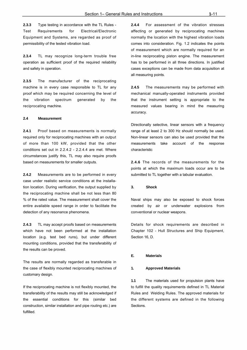
2.4.4 For assessment of the vibration stresses
affecting or generated by reciprocating machines
normally the location with the highest vibration loads
comes into consideration. Fig. 1.2 indicates the points
of measurement which are normally required for an
in-line reciprocating piston engine. The measurement
has to be performed in all three directions. In justified
cases exceptions can be made from data acquisition at
all measuring points.
2.4.5 The measurements may be performed with
mechanical manually-operated instruments provided
that the instrument setting is appropriate to the
measured values bearing in mind the measuring
accuracy.
Directionally selective, linear sensors with a frequency
range of at least 2 to 300 Hz should normally be used.
Non-linear sensors can also be used provided that the
measurements take account of the response
characteristic
2.4.6 The records of the measurements for the
points at which the maximum loads occur are to be
submitted to TL together with a tabular evaluation.
3. Shock
Naval ships may also be exposed to shock forces
created by air or underwater explosions from
conventional or nuclear weapons.
Details for shock requirements are described in
Chapter 102 - Hull Structures and Ship Equipment,
Section 16, D.
E. Materials
1. Approved Materials
1.1 The materials used for propulsion plants have
to fulfill the quality requirements defined in TL Material
Rules and Welding Rules. The approved materials for
the different systems are defined in the following
Sections.

1-12 Section 1 – General Rules and Instructions
Sides for measurement
L left side looking towards coupling flange
R right side looking towards coupling flange
Measuring height
0 bed
1 base
2 crankshaft height
3 frame top
Measuring point over engine length
I coupling side (KS)
II engine center
III opposite side to coupling (KGS)
1.2 Materials deviating from the defined quality
requirements may only be used with special approval of
TL. The suitability of the materials has to be proven.
F. Fuels and Consumables for Operation
1. All fuels and consumables used for the
operation of propulsion plants must be in accordance
with the requirements of the manufacturers. 2. The flash point (2) of liquid fuels for the
operation of boilers and diesel engines may not be
lower than 60°.
(2) Based, up to 60 °C, on determination of the flash
point in a closed crucible (cup test).
For emergency power generating sets, however, use
may be made of fuels with a flash point of ≥ 43 °C. The
fuel must enable a starting of the emergency generating
set at ambient temperatures of - 15 °C and above.
3. In exceptional cases, for ships intended for
operation in limited geographical areas or where
special precautions subject to TL approval are
taken, fuels with flash points between 43 °C and 60 °C
may also be used. This is conditional upon the
requirement that the temperatures of the spaces in
which fuels are stored or used must invariably be 10
°C below the flash point. 4. The fuel must be filterable.
Fig. 1.2 Schematic representation of in-line piston engine
Section 1– General Rules and Instructions 1-13 5. The fresh cooling water for internal combus-
tion engines has to be treated from freshwater and
corrosion protection agent.
Fresh water must comply with the requirements of the
engine manufacturer with respect to:
- water hardness [dGH]
- pH value (at 20 °C)
- chloride content [mg/l]
6. The storage of fuel and consumables for
operation has to follow the requirements of Chapter 107
- Ship Operation Installations and Auxiliary Systems,
Section 7.
G. Safety Equipment and Protective Measures
Machinery is to be installed and safeguarded in such a
way that the risk of accidents is largely ruled out.
Besides of national regulations particular attention is to
be paid to the following:
1. Moving parts, flywheels, chain and belt
drives, linkages and other components which could
constitute an accident hazard for the operating person-
nel are to be fitted with guards to prevent contact.
2. The design and installation of all systems and
equipment has to guarantee that elements, which have
to be used during normal operation of the ship by the
crew and where no thermal insulation is provided, are
kept within the following restrictions concerning
accidental contact of hot surfaces.
2.1 No skin contact is possible with elements
warmed up under operating conditions to surface
temperature above 70 °C.
2.2 Elements, which may be used without body
protection, e.g. protective gloves and with a contact
time up to 5 s, are to have no higher surface
temperature than 60 °C.
2.3 Elements made of materials with high
thermal conductivity, which may be used without
body protection and a contact time of more than 5 s are
not to achieve a surface temperature above 45 °C.
2.4 Therefore exhaust gas lines and other
apparatus and lines transporting hot media have to be
insulated effectively. Insulation material must be
non combustible. Locations where inflammable liquids
or moisture may penetrate into the insulation are to
be protected in a suitable way by coverings, etc.
3. When using hand cranks for starting internal
combustion engines, steps are to be taken to ensure
that the crank disengages automatically when the
engine starts.
Dead-Man's circuits are to be provided for rotating
equipment.
4. Blowdown and drainage facilities are to be
designed in such a way that the discharged medium
can be safely drained off.
5. In operating spaces, anti-skid floorplates and
floor coverings must be used.
6. Service gangways, operating platforms,
stairways and other areas open to access during
operation are to be safeguarded by guard rails. The
outside edges of platforms and floor areas are to be
fitted with coamings unless some other means is
adopted to prevent persons and objects from sliding off.
7. Safety valves and shutoffs must be capable of
safe operation. Fixed steps, stairs or platforms are to
be fitted where necessary.
8. Safety valves are to be installed to prevent
the occurrence of excessive operating pressures.
H. Survivability
1. Definition
Survivability of a naval ship is to be regarded as the
degree of ability to withstand a defined weapon threat
and to maintain at least a basic degree of safety and
operability of the ship.

1-14 Section 1 – General Rules and Instructions Survivability is threatened by:
- Loss of global strength of the hull structure
- Loss of buoyancy and/or stability
- Loss of manoeuvrability
- Fire in the ship and ineffective fire protection
or fire fighting capability
- Direct destruction of machinery, equipment
or control systems
- Direct destruction of weapons and sensors
- Threat to the crew
2. Measures for improved survivability
The design of a ship which is classed as naval ship has
to consider a series of possible measures to improve
survivability. These TL Rules for naval surface ships
offer in the different Chapters various measures and
Class Notations to achieve improved survivability. The
degree of including such measures in an actual project
has to be defined by the Naval Authority.
3. Measures for the propulsion plant
In this Chapter the following main measure to im-
prove survivability is included.
3.1 Redundant propulsion
The requirements for the Class Notations RP1 x% to
RP3 x% concerning redundant propulsion and
manoeuvrability are defined in Section 2, K.

Section 2– Design and Construction of the Machinery Installation 2-1
SECTION 2
DESIGN AND CONSTRUCTION OF THE MACHINERY INSTALLATION
A. General
1. As far as necessary for function and safe
operation, the design of the propulsion plant has to
consider the size and experience of the crew according
to the mission statement of the actual naval ship.
2. Normally it can be assumed, that:
- No personnel is permanently present in
machinery rooms
- In machinery rooms inspection patrols will be
made in regular time intervals
- The machinery control centre (MCC) is
permanently manned
3. The operating and maintenance instructions,
warning signs, etc. have to be prepared in English and
in the user's language.
B. Dimensions of Components
1. General 1.1 All parts must be capable of withstanding the
stresses and loads peculiar to shipboard service, e.g.
those due to movements of the ship, vibrations,
intensified corrosive attack, temperature changes and
wave impact, and must be dimensioned in accordance
with the requirements set out in the present Chapter.
The ambient conditions acc. to Section 1, D. and
Chapter 101 - Classification and Surveys and
Chapters 105 - Electrical Installations, 106 -
Automation and 107 - Ship Operation Installations and
Auxiliary Systems, have to be considered.
In the absence of rules governing the dimensions of
parts, the recognized rules of engineering practice are
to be applied.
1.2 Where connections exist between systems or
plant items which are designed for different forces,
pressures and temperatures (stresses), safety
devices are to be fitted which prevent the over-stressing
of the system or plant item designed for the lower
design parameters. To preclude damage, such
systems are to be fitted with devices affording
protection against excessive pressures and
temperatures and/or against overflow.
2. Materials
All components subject to these Rules must comply
with TL Material Rules.
3. Welding
The fabrication of welded components, the approval of
companies and the testing of welders are subject to TL
Welding Rules.
4. Screw connections
4.1 Screws are to be designed according to
proven and acknowledged principles.
4.2 The design of screw connections between
equipment and foundations has to avoid shear forces
or bending moments in the screws, only tensional
forces in axial direction are allowed. Therefore, the
flanges where the screw forces are acting have to be
stiffened with a suitable number of brackets to avoid
flange bending, which would create bending moments
to the screws.

2-2 Section 2 – Design and Construction of the Machinery Installation 4.3 Only closed holes in flanges shall be
provided for screws, because under shock
influence screws might slip out of a hole in form of a
half open slot. In addition friction connections are not
safe under shock influence.
Note :
If expansion screws are used, the peak stresses at the core of
the thread are reduced, because the maximum stress will
occur at the location of the reduced shaft section. If such
screws are long enough, they will be able to protect the
mounted equipment from shock loads to some extent,
because the elongation of the shaft reduces acceleration
peaks.
It is also recommendable to use cap nuts together with
expansion screws for connections. With this form of nut the
load on the different turns of the thread is nearly the same,
which helps to avoid excessive local stresses.
If a normal screw is fitted into a threaded hole, the breaking
of the screw because of the severe transverse dynamic shock
loads will be evident at the first turn of the thread coming out
of the hole. This is the case because of the adding up of the
bending stress to the maximum axial stress which occurs at
this turn. The problem can be solved by a flat necking of the
shaft above the last turn of the thread or by a special form of
shaft and hole. The bolt is in the latter case provided with a
small collar fitting in the upper part of the hole. Thus the
biggest part of the bending stress will be transmitted at the
collar and is separated from the axial stress at the thread.
5. Tests
5.1 Machinery and its component parts are
subject to constructional and material tests, pressure
and leakage tests, and trials. All the tests prescribed in
the following Sections are to be conducted under
supervision of TL.
In case of parts produced in series, other methods of
testing may be agreed with TL instead of the tests
prescribed, provided that the former are recognized as
equivalent by TL.
5.2 TL reserve the right, where necessary, to
increase the scope of tests and also to subject to
testing those parts which are not expressly required to
be tested according to the Rules.
5.3 Components subject to mandatory testing are
to be replaced by tested parts.
5.4 After installation on board of the main and
auxiliary machinery, operational functioning of the
machinery including associated ancillary equipment is
to be verified. All safety equipment is to be tested,
unless adequate testing has already been performed at
the manufacturer's works in the presence of the TL
Representative.
In addition, the entire machinery installation is to be
tested during sea trials, as far as possible under the
intended service conditions.
6. Corrosion protection
Parts which are exposed to corrosion are to be
safeguarded by being manufactured of corrosion-
resistant materials or provided with effective corrosion
protection.
C. Availability of Machinery
1. Ship's machinery is to be so arranged and
equipped that it can be brought into operation from the
"dead ship" condition with the means available on
board.
The "dead ship" condition means that the entire
machinery installation including the electrical power
supply is out of operation and auxiliary sources of
energy such as starting air, battery-supplied starting
current etc. are not available for restoring the ship's
electrical system, restarting auxiliary operation and
bringing the propulsion installation back into operation.
To overcome the "dead ship" condition use may be made
of an emergency generator set provided that it is ensured
that the electrical power for emergency services is
available at all times. It is assumed that means are
available to start the emergency generator at all times.
2. In case of "dead-ship" condition it must be
ensured that it will be possible for the propulsion
system and all necessary auxiliary machinery to be
Section 2– Design and Construction of the Machinery Installation 2-3 restarted within a period of 30 minutes, see Chapter 105
- Electrical Installations, Section 3, C. 1.5.
D. Control and Regulating
1. Machinery must be so equipped that it can be
controlled in accordance with operating requirements in
such a way that the service conditions prescribed by the
manufacturer can be met.
1.1 For the control equipment of main engines and
systems essential for operation see Chapters 105 -
Electrical Installations, 106 - Automation and 107 - Ship
Operation Installations and Auxiliary Systems.
2. In the event of failure or fluctuations of the
supply of electrical, pneumatic or hydraulic power to
regulating and control systems, or in case of a break in
a regulating or control circuit, steps must be taken to
ensure that:
- the appliances remain at their present
operational setting or, if necessary, are
changed to a setting which will have the
minimum adverse effect on operation (fail-safe
conditions)
- the power output or engine speed of the
machinery being controlled or governed is
not increased
- no unintentional start-up sequences are
initiated
3. Each driving machinery has to be provided
with an emergency stopping device.
4. Manual operation
Every functionally important, automatically or remote
controlled system must also be capable of manual
operation, see also the Rules in Chapter 106 -
Automation, Sections 7 and 8.
A manual emergency stopping device has to be
provided.
E. Propulsion Plant 1. General
1.1 All devices forming a part of the propulsion
plant have to be provided with peripheral components
which ensure a faultless handling as well as a simple
and safe operation and control, even if they are not
specified in detail. 1.2 All auxiliary machinery and the control units
directly needed for the operation of the propulsion
plant are to be located as near as possible to the
driving machinery.
1.3 Manoeuvring equipment
Every engine control stand is to be equipped in such a
way that:
- the propulsion plant can be adjusted to any
setting
- the direction of propulsion can be reversed
- the propulsion unit or the propeller shaft can
be stopped
1.4 The driving machinery has to be designed
and equipped for operation in a sound protection
capsule.
Using sound protection capsules the relative
movement between the driving machinery and the
shipside piping system has to be compensated by
flexible connections. If applicable, the elastic mounting
of the driving machinery has to be taken into account.
1.5 For connected pumps no electrically driven
stand by pumps are to be provided if the propulsion is
ensured by several driving machines.
2. Multiple shaft and multi-engine systems 2.1 Definitions
2.1.1 CODAD
CODAD is the abbreviation for COmbined Diesel

2-4 Section 2 – Design and Construction of the Machinery Installation engine And Diesel engine. In this configuration a
propulsion shaft can be driven alternatively by one
diesel engine or several diesel engines, see Fig. 2.1.
2.1.2 CODAG
CODAG is the abbreviation for COmbined Diesel
engine And Gas turbine. In this configuration a pro-
pulsion shaft can be driven alternatively by a diesel
engine or by a gas turbine or by both, see Fig. 2.2.
2.1.3 CODOG
CODOG is the abbreviation for COmbined Diesel
engine Or Gas turbine. In this configuration a propulsion
shaft can be driven alternatively by a diesel engine or a
gas turbine, see Fig. 2.3.
2.1.4 COGAG
COGAG is the abbreviation for COmbined Gas turbine
And Gas turbine. In this configuration a propulsion shaft
can be driven alternatively by one gas turbine or by
several gas turbines, see Fig. 2.4.
2.1.5 COGOG
COGOG is the abbreviation for COmbined Gas turbine
Or Gas turbine. In this configuration a propulsion shaft
can be driven alternatively by one or the other gas
turbine, see Fig. 2.5.
2.2 If a ship is equipped with several propulsion
machines, it must be possible to disengage the different
propulsion engines from the power transmitting unit. At
manual or automatic emergency stops of an engine, the
relevant clutch must disconnect automatically.
2.3 Steps are to be taken to ensure that in the
event of a failure of a propulsion engine, operation can
be maintained with remaining engines, where
appropriate by a simple change-over system.
2.4 Multiple shaft systems
A space separation between driving engines and driving
gear shall be provided, if possible.
All necessary provisions have to be made, that:
- Only one propulsion shaft can be used and no
overloading occurs
- Starting and operation is possible with every
driving engine intended to drive a propulsion
shaft, independently from the other propulsion
shafts
For Class Notation redundant propulsion (RP) see K.
For multiple-shaft systems, each shaft is to be
provided with a locking device which prevents dragging
of the shaft.
F. Turning Appliances
1. Machinery is to be equipped with the
necessary turning appliances. 2. The turning appliances are to be of self-
locking type. Electric motors are to be fitted with
suitable retaining brakes.
3. An automatic interlocking device is to be
provided to ensure that the propulsion installation
cannot start up while the turning gear is engaged. In
case of manual turning installations warning devices
may be provided alternatively.
G. Operating and Maintenance Instructions
Manufacturers of machinery, boilers and auxiliary
equipment must supply a sufficient number of operating
and maintenance notices and manuals together with
the equipment.
In addition, an easily legible board is to be mounted
on boiler operating platforms giving the most important
operating instructions for boilers and oil-firing
equipment.
H. Markings, Identification
In order to avoid unnecessary operating and switching
errors, all parts of the machinery which function is not
immediately apparent are to be adequately marked and
labelled.

Section 2– Design and Construction of the Machinery Installation 2-5
Figure 2.1 Principle arrangement for CODAD propulsion plants
Figure 2.2 Principle arrangement for CODAG propulsion plants
Figure 2.3 Principle arrangement for CODOG propulsion plants
Figure 2.4 Principle arrangement for COGAG propulsion plants

2-6 Section 2 – Design and Construction of the Machinery Installation
Figure 2.5 Principle arrangement for COGOG propulsion plants
I. Engine Room Equipment 1. Operating and monitoring equipment 1.1 Instruments, warning and indicating systems
and operating appliances are to be clearly displayed
and conveniently sited. Absence of dazzle, particularly
on the bridge, is to be ensured.
Operating and monitoring equipment is to be grouped in
such a way as to facilitate easy supervision and control
of all important parts of the installation.
The following requirements are to be observed when
installing systems and equipment:
- protection against humidity and the effects of dirt
- avoidance of excessive temperature variations
- adequate ventilation
In consoles and cabinets containing electrical or
hydraulic equipment or lines carrying steam or water the
electrical gear is to be protected from damage due to
leakage. Redundant ventilation systems are to be
provided for air-conditioned machinery and control
rooms.
1.2 Pressure gauges
The scales of pressure gauges are to be dimensioned
up to the specified test pressure. The maximum
permitted operating pressures are to be marked on the
pressure gauges for boilers, pressure vessels and in
systems protected by safety valves. Pressure gauges
must be installed in such a way that they can be
isolated.
Lines leading to pressure gauges must be installed in
such a way that the readings cannot be affected by
liquid heads and hydraulic hammering.
2. Accessibility of machinery and boilers
2.1 Machinery and boiler installations,
apparatuses, control and operating devices must be
easily accessible and visible for operation and
maintenance. A minimum aisle width of 600 mm and
a passage height of 2 050 mm have to be provided,
stumbling locations have to be avoided. 2.2 For the layout of machinery spaces (design of
foundation structures, laying of pipelines and cable
conduits, etc.) and for the design of machinery and
equipment (mountings for filters, coolers, etc.) 2.1 is to
be complied with.
For the installation and the dismantling of the propulsion
machinery, openings of sufficient size have to be
provided; for all other parts of the equipment installation
and dismantling routes have to be planned.
Fixtures for transport devices have to be provided.
The installation of components within the installation
routes has to be avoided or the components must be
dismountable.
Section 2– Design and Construction of the Machinery Installation 2-7 3. Machinery control centre
Machinery control centres (MCC) are to be provided
with at least two exits, one of which can also be used
as an escape route.
4. Lighting
All operating spaces must be adequately lit to ensure
that control and monitoring instruments can be easily
read. In this connection see the rules defined in Chapter
105 - Electrical Installation, Section 11.
5. Bilge wells/ bilges
See rules defined in Chapter 107 - Ship Operation Instal-
lations and Auxiliary Systems, Section 8.
6. Ventilation
The design and construction of ventilation systems
are subject to the requirements defined in Chapter 107 -
Ship Operation Installations and Auxiliary Systems,
Section 11.
7. Noise abatement
In compliance with the relevant national regulations,
care is to be taken to ensure that operation of the ship
is not unacceptably impaired by engine noise, e.g. by
means of shielding.
J. Communication and Signalling Equipment 1. Oral communication
Means of oral communication are to be provided
between the ship's manoeuvring station, the engine
room and the steering gear compartment, and these
means shall allow fully satisfactory intercommunication
independent from the shipboard power supply under
all operating conditions (see also Chapter 105 -
Electrical Installations, Section 9).
2. Duty alarm system
From the engine room or the machinery control centre a
duty alarm system for the engineer officers has to be
established for the off-duty period. See also Chapter
106 - Automation, Section 3, C.
3. Engine telegraph
Machinery operated from the engine room must be
equipped with a telegraph.
In the case of multiple-shaft installations, a telegraph
must be provided for each unit.
Local control stations are to be equipped with an
emergency telegraph.
4. Shaft revolution indicator
The speed and direction of rotation of the propeller
shafts are to be indicated on the bridge, in the engine
room respectively in all control stations. In the case of
small propulsion units, the indicator may be dispensed
with.
5. Design of communication and signaling equipment
Reversing, command transmission and operating con-
trols etc. are to be grouped together at a convenient
point on the control platform.
The current status, "Ahead" or "Astern", of the reversing
control is to be clearly indicated on the propulsion plant
control platform.
Signalling devices must be clearly perceptible from all
parts of the engine room when the machinery is in full
operation.
For details of the design of electrically operated
command transmission, signalling and alarm systems,
see Chapter 105 - Electrical Installations and 106 -
Automation.
K. Redundant Systems
1. General
1.1 The Rules relating to redundant propulsion
and steering systems apply to ships, which are

2-8 Section 2 – Design and Construction of the Machinery Installation classified by TL and are to receive the Notation RP1 x%, RP2 x% or RP3 x% affixed to the Character of
Classification. 1.2 The Rules for redundant propulsion and
steering systems stipulate the level of redundancy for
the propulsion and steering systems. It is characterized
by the appropriate Notation to be affixed to the Character
of Classification as defined in Chapter 101 -
Classification and Surveys, Section 2, C.
1.3 The Rules are based on the single-failure
concept.
1.4 Documents for approval 1.4.1 Compliance in accordance with the Notation
applied for must be demonstrated by block diagrams,
schematic drawings, descriptions of system functions
and operation, calculations and arrangement plans.
Model tests or calculations shall be used to show the
speed and manoeuvring qualities that have to be
attained during sea trials in order to demonstrate
compliance with the requirements set out in 2.
1.4.2 A failure mode and effects analysis (FMEA) or
an equivalent analysis must be conducted for the
propulsion and steering systems, and for the auxiliary
systems and control systems needed to operate them.
The analysis must demonstrate that a single failure
cannot lead to any loss in propulsion and/or in steering
ability in accordance with the requirements set out in 2.
The analysis shall further demonstrate that measures
are in place for failure detection and control of possible
effects and that these measures are adequate to
ensure in particular that the propulsion and steering of
the ship can be rapidly restored.
In addition, the analysis must deal with the identification
of possible failure conditions, which have a common
cause. The identification of technical elements and/or
operational procedures, which could undermine the
redundancy concept, must also be accounted for.
For the Notation RP1 x%, the FMEA only has to be
performed for the redundant propulsion machines and
their requisite auxiliary systems. The events of water
ingress or fire in a machinery compartment, and a
failure of any of the common elements of the propulsion
train related to this Notation do not have to be
considered.
For the Notation RP2 x%, the FMEA has to be
performed for the redundant propulsion and steering
systems and their requisite auxiliary systems. The
events of water ingress or fire in a machinery
compartment and water ingress in a steering gear
compartment do not have to be considered.
1.4.3 A programme of tests to be conducted
during sea trials must be submitted for approval. 2. General requirements In accordance with the requirements set out in these Rules, it must be ensured that when a failure in a propulsion or steering system occurs,
2.1 the manoeuvrability of the ship can be
maintained so that even under unfavourable weather
conditions (1) the ship can be manoeuvred into a
position of less resistance to the weather and can be
maintained in this position,
2.2 a minimum speed can be maintained to keep
the ship under control and ensure that it is able to
make speed over the ground in waters where there is a
strong current. The minimum speed under normal
weather conditions (2) must be at least 7 knots or
half the speed v0 (the lower value may be applied),
2.3 the requirements stated in 2.1 and 2.2 can be
met for a minimum period of 72 hours (3) .
(1) Within the context of these Rules, unfavourable
weather conditions are regarded as being a wind speed of up to
and including 21 m/s (8 on the Beaufort scale) and a significant
wave height of 5,4 m with an average wave period of 8,3 s.
(2) Normal weather conditions are regarded as being a
wind speed of up to and including 11 m/s (5 on the Beaufort
scale) and a significant wave height of 2,8 m with an average
wave period of 6,7 s.
(3) For ships, which normally spend less than 72 hours
cruising at sea, the period specified may be limited to the
maximum time of a voyage.

Section 2– Design and Construction of the Machinery Installation 2-9 2.4 the requirements stated in 2.1, 2.2 and 2.3 can
be met irrespective of the ship's loading condition,
2.5 the redundant propulsion systems and
steering systems are ready for operation at any time
and can be activated on demand,
2.6 the redundant propulsion system is capable of
taking up operation from a still standing propulsion
plant.
Compliance with the above requirements must be
demonstrated by calculations and/or model tests and
verified in a suitable manner during sea trials.
3. Requirements for auxiliary systems
3.1 Auxiliary systems for redundant propulsion
systems which function have a direct effect on the
propulsion system, for example fuel, lubrication oil,
cooling water, control air and uninterrupted power
supply systems, must be provided for each propulsion
system independently of each other.
Where standby units are specified for these systems in
accordance with TL Rules, these must be provided for
each of the systems in question.
3.2 Auxiliary systems for redundant propulsion
systems which failure do not have a direct effect on
the propulsion system, such as fuel treatment, starting
air supply systems etc. are to be designed to be sepa-
rate from each other. For these systems no additional
standby units have to be provided if interconnection
lines are provided between the systems and if the units
are designed so that the propulsion systems can be
supplied with power simultaneously without restriction.
In the connection lines shut-off valves are to be
provided which must be kept closed during normal
operation.
On ships with Class Notation RP3 x%, a shut-off
valve must be fitted on either side of the partition
bulkhead between the machinery compartments.
3.3 In fuel oil systems, the heating facilities for
preheating the fuel oil must be designed so that if one
propulsion system fails, the required preheating of the
fuel oil for the redundant propulsion system can be
ensured.
It is not necessary to provide a redundant heating
facility if diesel oil storage tanks are provided which
allow unrestricted operation for the redundant propulsion
system for the period of time specified in 2.3.
3.4 Supply lines from fuel oil service tanks of
redundant propulsion systems must be provided with
an interconnection fitted between service tank and
pump of each system. The interconnection is to be
provided with a shut-off device, which must be kept
closed during normal operation.
On ships with Class Notation RP3 x%, a shut-off
valve must be fitted on either side of the partition
bulkhead between the machinery compartments.
3.5 The seawater supply of redundant propulsion
systems may be achieved via a common sea chest
connection by means of a pump assigned to each
propulsion system. The systems must be capable of
being isolated by means of a shut-off valve in the
connection line.
On ships with Class Notation RP3 x% the sea chests
are to be installed in separate compartments in
accordance with 5.1. The shut-off valve in the
connection line must be fitted to the partition
bulkhead and be capable of being operated either from
both machinery compartments or from a position
outside the machinery compartments.
3.6 On ships with Class Notation RP3 x% it must
be possible to operate the redundant propulsion system
when one of the seawater cooling systems fails, in
accordance with the compartment separation
requirements specified in 5.1.
4. Requirements for steering systems
4.1 Rudders
Every redundant steering system must consist of a
main and an auxiliary steering gear, each with
independent control.
The rudder position must be indicated by means of
electrically independent rudder position indicators.
2-10 Section 2 – Design and Construction of the Machinery Installation The ship's steering capability must be ensured even
when the rudder is blocked at maximum deflection. If
the steering ability is impaired to the extent that the
requirements set out in 2. cannot be met, it must be
possible to move and lock the failed rudder into the
midships position.
4.2 Azimuth propulsion units as steering systems
Where ship steering is exclusively performed by
azimuth propulsion systems, at least two azimuth
propulsion systems must be provided, each with
independent controls.
The position of the individual azimuth propulsion
systems must be indicated by electrically independent
indicators.
If the ship's steering ability is impaired, even when the
propulsion of a defective azimuth propulsion system is
disconnected, to the extent that the requirements stated
in 2. cannot be met, it must be possible to move and to
lock the defective azimuth propulsion unit into the
midships position.
5. Compartment Separation Requirements for RP3 x%
5.1 Bulkheads and partitions
5.1.1 Redundant propulsion systems and steering
systems must be separated from each other by
watertight bulkheads. 5.1.2 Partitions between machinery compartments
containing redundant propulsion systems must comply
with a fire resistance, the level of which depends on
the fire potential of the machinery compartments. The
partitions must keep their structural integrity in case of
fire for at least 60 minutes. Fire insulation shall be
provided if the function of essential machinery and
equipment could be adversely affected.
5.1.3 Partition walls of machinery compartments, which
are isolated from each other by tanks, cofferdams or
other void spaces, must keep their structural integrity in
case of fire for at least 60 minutes. The length or depths
of that spaces shall be at least 500 mm.
5.1.4 Watertight doors may be permitted in
accordance with SOLAS II-1 / Reg. 18 or Reg. 15
respectively. These have to be equipped with an
open/closed status indication and a remote control
facility on the bridge.
Watertight doors must not be regarded as emergency
exits for machinery compartments.
5.2 Ventilation
Machinery compartments are to be fitted with inde-
pendent ventilation systems.
6. Tests
Tests are to be performed during sea trials in
accordance with an approved sea trial program. The
tests are designed to prove that:
- the ship is able to meet the requirements
defined
- the propulsion and steering systems have the
necessary redundancy in line with the Notation
applied for
- the conclusions drawn in the FMEA regarding
the effects of failure conditions and measures
to detect and control these failure conditions
are correct and adequate
7. Further details
Further details concerning redundant systems are
defined in Chapter 105, Electrical Installations and in
the TL Rules for Classification and Construction,
Chapter 23 - Redundant Propulsion and Steering
Systems.

Section 3– Internal Combustion Engines 3-1
SECTION 3
INTERNAL COMBUSTION ENGINES
A. General
1. Scope
The Rules contained in this Section are valid for internal
combustion engines as main and auxiliary drives.
Internal combustion engines in the sense of these
Rules are four-stroke diesel engines with trunk piston.
2. Ambient conditions
For all engines, which are used on ships with
unrestricted range of service, the definition of the
performance has to be based on the ambient conditions
according to Section 1, D.
3. Rated power
3.1 Diesel engines are to be designed such that
their rated power when running at rated speed
according to the definitions of the engine
manufacturer at ambient conditions as defined in
Section 1, D. can be delivered as continuous power.
Diesel engines are to be capable of continuous
operation within power range in Fig. 3.1 and of
short period operation in power range . The extent
of the power ranges are to be stated by the engine
manufacturer.
3.2 Continuous power is understood to mean the
service standard power which an engine is capable of
delivering continuously, provided that the
maintenance prescribed by the engine manufacturer is
carried out, between the maintenance intervals stated
by the engine manufacturer.
3.3 To verify that an engine is rated at its
continuous power, it is to be demonstrated that the
engine can run at an overload power corresponding to
110 % of its rated power at corresponding speed for an
uninterrupted period of 1 hour. Deviations from the
overload power value require the agreement of TL.
3.4 Engines, which have to meet the
requirements of a permanent low-load operation
according to the mission statement of the naval ship,
have to be designed with regard to bad combustion
and low temperatures. Relevant measures and
additional equipment have to be approved by TL.
3.5 After running on the test bed, the fuel delivery
system of main engines is normally to be so adjusted
that overload power cannot be given in service. The
limitation of the fuel delivery system has to be secured
permanently.
3.6 Subject to the prescribed conditions, diesel
engines driving electric generators must be capable of
overload operation even after installation on board.
3.7 Subject to the approval by TL, diesel engines
may be designed for a continuous power (fuel stop
power) which cannot be exceeded.
3.8 For main engines, a power diagram (Fig. 3.1)
is to be prepared showing the power ranges within
which the engine is able to operate continuously and
for short periods under service conditions.
4. Fuels
4.1 The use of liquid fuels is subject to the Rules
contained in Section 1, F.
4.2 For fuel treatment and supply, see Chapter
107 - Ship Operation Installations and Auxiliary Systems,
Section 7, B. and Section 8, G.
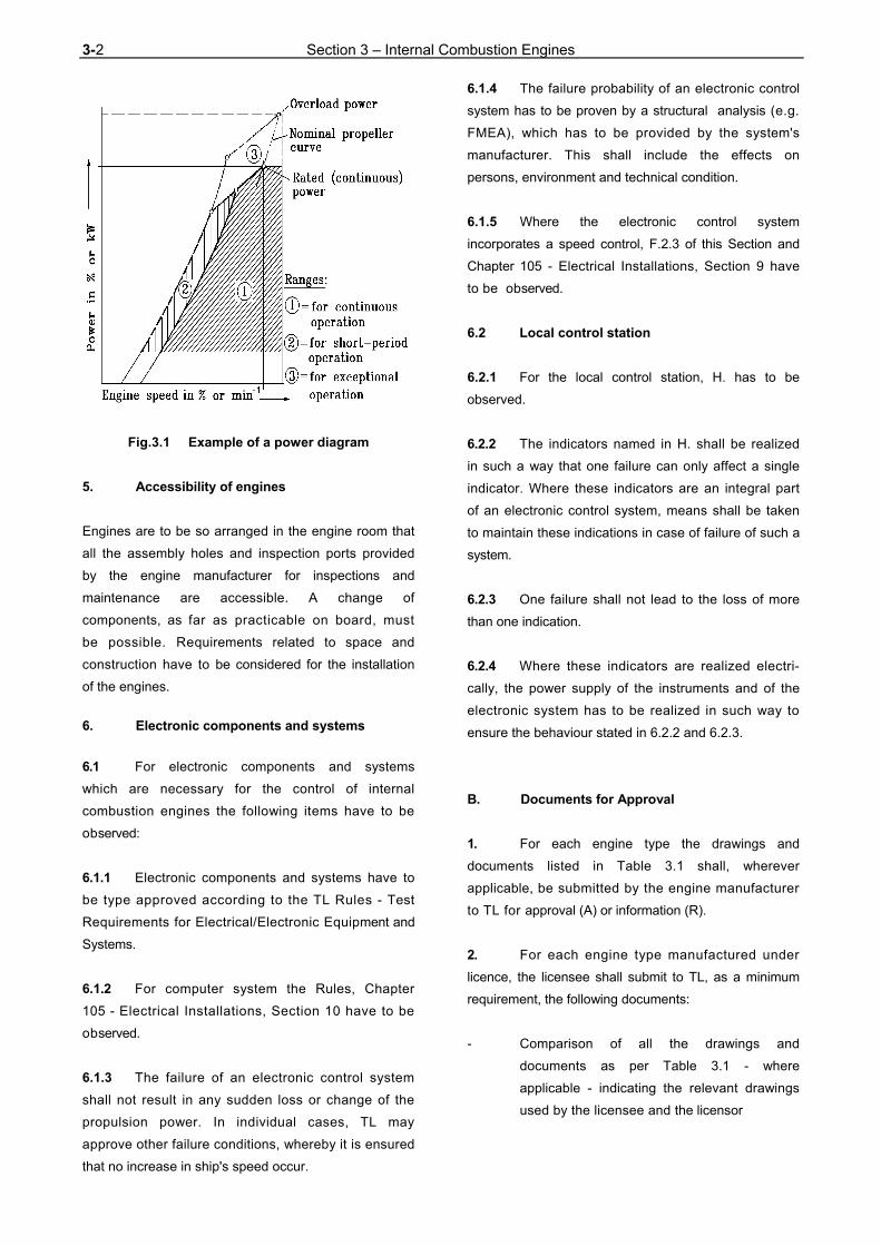
3-2 Section 3 – Internal Combustion Engines
Fig.3.1 Example of a power diagram
5. Accessibility of engines
Engines are to be so arranged in the engine room that
all the assembly holes and inspection ports provided
by the engine manufacturer for inspections and
maintenance are accessible. A change of
components, as far as practicable on board, must
be possible. Requirements related to space and
construction have to be considered for the installation
of the engines.
6. Electronic components and systems
6.1 For electronic components and systems
which are necessary for the control of internal
combustion engines the following items have to be
observed:
6.1.1 Electronic components and systems have to
be type approved according to the TL Rules - Test
Requirements for Electrical/Electronic Equipment and
Systems.
6.1.2 For computer system the Rules, Chapter
105 - Electrical Installations, Section 10 have to be
observed.
6.1.3 The failure of an electronic control system
shall not result in any sudden loss or change of the
propulsion power. In individual cases, TL may
approve other failure conditions, whereby it is ensured
that no increase in ship's speed occur.
6.1.4 The failure probability of an electronic control
system has to be proven by a structural analysis (e.g.
FMEA), which has to be provided by the system's
manufacturer. This shall include the effects on
persons, environment and technical condition.
6.1.5 Where the electronic control system
incorporates a speed control, F.2.3 of this Section and
Chapter 105 - Electrical Installations, Section 9 have
to be observed.
6.2 Local control station
6.2.1 For the local control station, H. has to be
observed.
6.2.2 The indicators named in H. shall be realized
in such a way that one failure can only affect a single
indicator. Where these indicators are an integral part
of an electronic control system, means shall be taken
to maintain these indications in case of failure of such a
system.
6.2.3 One failure shall not lead to the loss of more
than one indication.
6.2.4 Where these indicators are realized electri-
cally, the power supply of the instruments and of the
electronic system has to be realized in such way to
ensure the behaviour stated in 6.2.2 and 6.2.3.
B. Documents for Approval
1. For each engine type the drawings and
documents listed in Table 3.1 shall, wherever
applicable, be submitted by the engine manufacturer
to TL for approval (A) or information (R).
2. For each engine type manufactured under
licence, the licensee shall submit to TL, as a minimum
requirement, the following documents:
- Comparison of all the drawings and
documents as per Table 3.1 - where
applicable - indicating the relevant drawings
used by the licensee and the licensor

Section 3– Internal Combustion Engines 3-3
Table 3.1 Documents for approval
Serial No.
A/R Description Quantity Remarks
(see below)1
R Details required on TL forms F 144 and F 144/1 when applying for approval of an internal combustion engine
3
2 R Engine transverse cross-section 3 3 R Engine longitudinal section 3
4 R A
Bedplate or crankcase - cast - welded, with welding details and instructions
1 3
5 A Thrust bearing assembly 3 (3) 6
R A
Thrust bearing baseplate: - cast - welded, with welding details and instructions
1 3
(3) (3)
7
R A
Frame/column: - cast - welded, with welding details and instructions
1 3
(1) (1)
8 R Tie rod 1 9 R Cylinder cover, assembly 1
10 R Cylinder jacket or engine block 1 (1) (2) 11 R Cylinder liner 1 (2) 12
A Crankshaft for each number of cylinders, with data sheets for calculation of crankshafts
3
13 A Crankshaft assembly, for each number of cylinders 3 14 A Thrust shaft or intermediate shaft (if integral with engine) 3 15 A Coupling bolts 3 16 A Counterweights including fastening bolts 3 17 R Connecting rod, details 3 18 R Connecting rod, assembly 3 (2) 19 R Piston assembly 1 20 R Camshaft drive, assembly 1 21
A Material specifications of main parts with information on non-destructive material tests and pressure tests
3
22 A Arrangement of foundation bolts (for main engines only) 3 23 A Schematic layout or other equivalent documents of starting air system 3 (6) 24 A Schematic layout or other equivalent documents of fuel oil system 3 (6) 25 A Schematic layout or other equivalent documents of lubricating oil system 3 (6) 26 A Schematic layout or other equivalent documents of cooling water system 3 (6) 27 A Schematic diagram of engine control and safety system 3 (6) 28 A Schematic diagram of electronic components and systems 29 R Shielding and insulation of exhaust pipes, assembly 1 30 A Shielding of high-pressure fuel pipes, assembly 3 (4) 31 A Arrangement of crankcase explosion relief valves 3 (5) 32 R Additional equipment for continuous low load operation 33 R Operation and service manuals 1
A for approval R for reference (1) only for one cylinder (2) only necessary if sufficient details are not shown on the transverse cross section and longitudinal section (3) if integral with engine and not integrated in the bedplate (4) for all engines (5) only for engines with a bore > 200 mm, or a crankcase volume ≥ 0,6 m3 (6) and the entire system, if this is part of the goods to be supplied by the engine manufacturer, requirements acc. to
the Rules, see Chapter 107 - Ship Operation Installations and Auxiliary Systems

3-4 Section 3 – Internal Combustion Engines
- All drawings of modified components, if
available, as per Table 3.1 together with the
licensor's declaration of consent to the
modifications
- Documents concerning measures, respectively
additional equipment for low load operation
- A complete set of drawings at the disposal of
the local inspection office of TL as a basis for
the tests and inspections
3. The type specification of an internal
combustion engine is defined by the following data:
- Manufacturer's type designation
- Cylinder bore
- Stroke
- Injection system
- Fuels which can be used
- Working cycle
- Scavenging system (naturally aspirated or
supercharged)
- Rated power per cylinder at rated speed and
maximum continuous brake mean effective
pressure
- Supercharging system (pulsating pressure
system or constant-pressure system)
- Charge air cooling system
- Cylinder arrangement (in-line, vee)
4. Following initial approval of an engine type by
TL, only those documents listed in Table 3.1 require
to be resubmitted for examination which em-body
important design modifications.
5. Where considered necessary, TL may request
further documents to be submitted.
6. The approval of exhaust gas turbochargers,
heat exchangers, engine-driven pumps, etc. is to be
requested from TL by the respective manufacturer.
7. Torsional vibrations, critical speeds
The rules defined in Section 8 are to be applied.
C. Crankshaft Design
1. Design methods
1.1 Crankshafts shall be designed to withstand
the stresses occurring when the engine runs at rated
power. Calculations are to be based on the TL Rules
Guid- elines for the Calculation of Crankshafts for I.C.
Engines, as amended. Other methods of calculation
may be used provided that they do not result in
crankshaft dimensions smaller than those obtained by
applying the aforementioned regulations. The
documentation has to be submitted for approval.
1.2 Outside the end bearings, crankshafts
designed according to the requirements specified in
1.1 may be adapted to the diameter of the adjoining
shaft by a generous fillet (r ≥ 0,06 · d) or a taper.
1.3 Design methods for application to
crankshafts of special construction and to the
crankshafts of engines of special type are to be agreed
with TL.
2. Shrink joints of built-up crankshafts
The shrink joints of built-up crankshafts are to be
designed in accordance with the TL Guidelines as
defined in 1.1
3. Screw joints
3.1 Split crankshafts
Only fitted bolts may be used for assembling split
crankshafts.

Section 3– Internal Combustion Engines 3-5
3.2 Power-end flange couplings
The bolts used to connect power-end flange couplings
are normally to be designed as fitted bolts in
accordance with Section 5, D.4.
If the use of fitted bolts is not feasible, TL may agree to
the use of an equivalent frictional resistance
transmission.
D. Materials
1. Approved materials
1.1 The mechanical characteristics of materials
used for the components of diesel engines must
conform to TL Materials Rules. The materials approved
for the various components are shown in Table 3.3
together with their minimum required characteristics.
1.2 Materials with properties deviating from those
specified may be used only with TL's special
approval. Proof of the suitability of such materials has to
be given.
1.3 If shock loads gain great importance for the
naval ship, cast iron with lamellar graphit (GG) is not
recommended for components exposed to such
loads. It may only be used if it is proven that the shock
loads are sufficiently reduced by adequate mountings.
2. Testing of materials
2.1 In the case of individually produced
engines, the following parts are to be subjected to
material tests in the presence of the TL representative.
1. Crankshaft
2. Crankshaft coupling flange (non-integral) for
main power transmission
3. Crankshaft coupling bolts
4. Pistons or piston crowns made of steel, cast
steel or nodular cast iron
5. Cylinder liners made of steel or cast steel
6. Cylinder covers made of steel or cast steel
7. Welded bedplates:
- plates and bearing transverse girders
made of forged or cast steel
8. Welded frames and crankcases
9. Welded entablatures
10. Tie rods
11. Exhaust gas turbocharger:
- shaft and rotor
12. Bolts and studs for:
- cylinder covers
- main bearings
- connecting rod bearings
13. Camshaft drive gear wheels and chain wheels
made of steel or cast steel.
2.1.1 Materials tests are to be performed in
accordance with Table 3.2.
Table 3.2 Material tests
Cylinder bore
Parts to be tested (numbered according to
the list under D.2.1 above)
≤ 300 mm 1 - 7 - 8 - 9 - 1 0
> 300 ≤ 400 mm 1 - 5 - 6 - 7 - 8 - 9 -
10-12-13
> 400 mm all parts
2.1.2 In addition, material tests are to be carried
out on pipes and parts of the starting air system and
other pressure systems forming part of the engine,
see Chapter 107 - Ship Operation Installations and
Auxiliary Systems, Section 8.
2.2 In the case of individually manufactured
engines, non-destructive material tests are to be
performed on the parts listed below in accordance
with Tables 3.4 and 3.5:
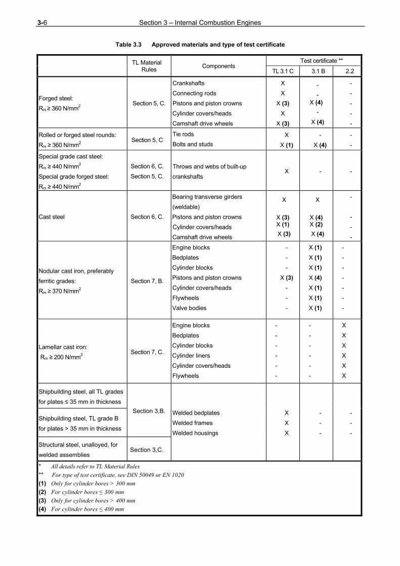
3-6 Section 3 – Internal Combustion Engines
Table 3.3 Approved materials and type of test certificate
TL Material
Rules Components
Test certificate **
TL 3.1 C 3.1 B 2.2
Forged steel:
Rm ≥ 360 N/mm2 Section 5, C.
Crankshafts
Connecting rods
Pistons and piston crowns
Cylinder covers/heads
Camshaft drive wheels
X
X
X (3)
X
X (3)
-
- X (4)
-
X (4)
-
-
-
-
-
Rolled or forged steel rounds:
Rm ≥ 360 N/mm2 Section 5, C
Tie rods
Bolts and studs
X
X (1)
-
X (4)
-
-
Special grade cast steel:
Rm ≥ 440 N/mm2
Special grade forged steel:
Rm ≥ 440 N/mm2
Section 6, C.
Section 5, C.
Throws and webs of built-up
crankshafts X - -
Cast steel Section 6, C.
Bearing transverse girders
(weldable)
Pistons and piston crowns
Cylinder covers/heads
Camshaft drive wheels
X
X (3) X (1)
X (3)
X
X (4) X (2)
X (4)
-
-
-
-
Nodular cast iron, preferably
ferritic grades:
Rm ≥ 370 N/mm2
Section 7, B.
Engine blocks
Bedplates
Cylinder blocks
Pistons and piston crowns
Cylinder covers/heads
Flywheels
Valve bodies
-
-
-
X (3)
-
-
-
X (1)
X (1)
X (1)
X (4)
X (1)
X (1)
X (1)
-
-
-
-
-
-
-
Lamellar cast iron:
Rm ≥ 200 N/mm2 Section 7, C.
Engine blocks
Bedplates
Cylinder blocks
Cylinder liners
Cylinder covers/heads
Flywheels
-
-
-
-
-
-
-
-
-
-
-
-
X
X
X
X
X
X
Shipbuilding steel, all TL grades
for plates ≤ 35 mm in thickness
Section 3,B. Welded bedplates
Welded frames
Welded housings
X
X
X
-
-
-
-
-
-
Shipbuilding steel, TL grade B
for plates > 35 mm in thickness
Structural steel, unalloyed, for
welded assemblies Section 3,C.
* All details refer to TL Material Rules
** For type of test certificate, see DIN 50049 or EN 1020
(1) Only for cylinder bores > 300 mm
(2) For cylinder bores ≤ 300 mm
(3) Only for cylinder bores > 400 mm
(4) For cylinder bores ≤ 400 mm
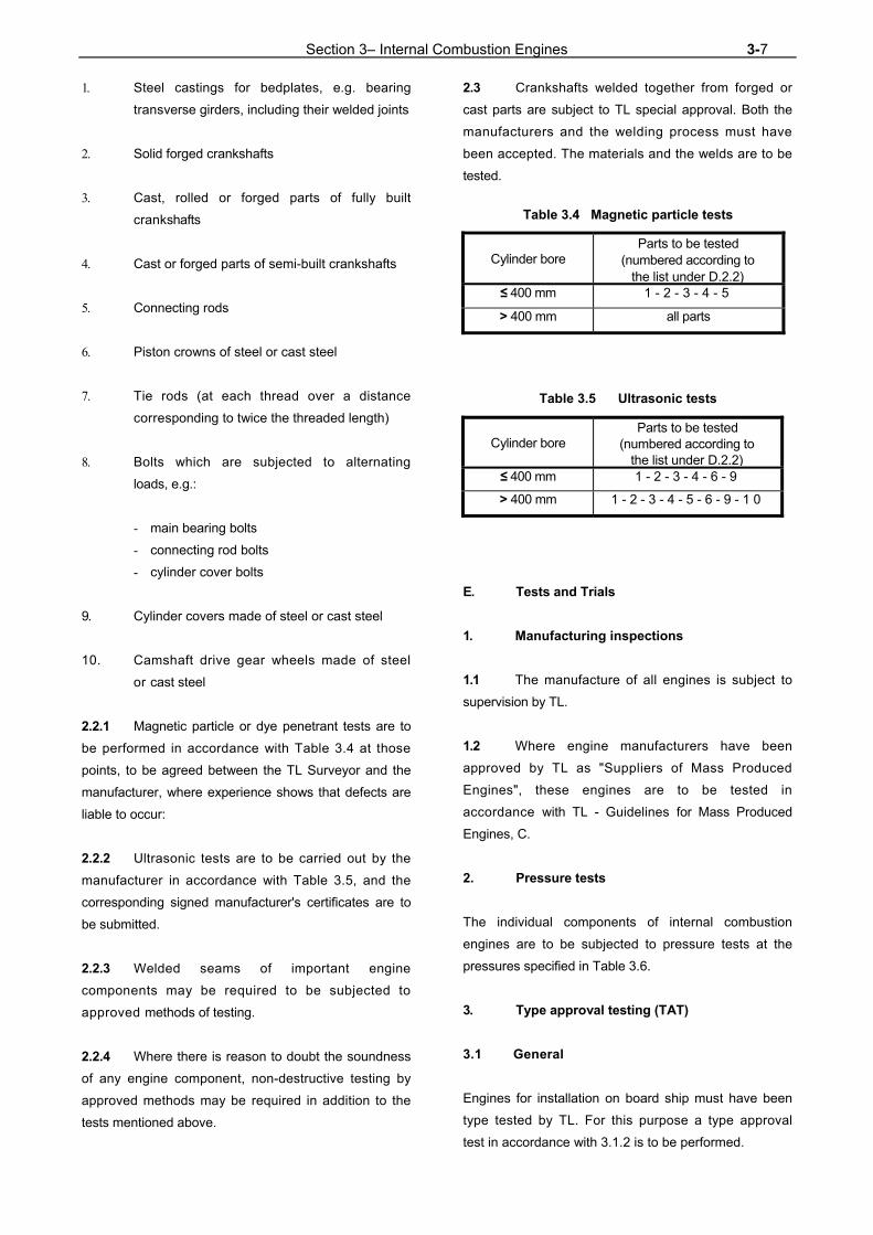
Section 3– Internal Combustion Engines 3-7
1. Steel castings for bedplates, e.g. bearing
transverse girders, including their welded joints
2. Solid forged crankshafts
3. Cast, rolled or forged parts of fully built
crankshafts
4. Cast or forged parts of semi-built crankshafts
5. Connecting rods
6. Piston crowns of steel or cast steel
7. Tie rods (at each thread over a distance
corresponding to twice the threaded length)
8. Bolts which are subjected to alternating
loads, e.g.:
- main bearing bolts
- connecting rod bolts
- cylinder cover bolts
9. Cylinder covers made of steel or cast steel
10. Camshaft drive gear wheels made of steel
or cast steel
2.2.1 Magnetic particle or dye penetrant tests are to
be performed in accordance with Table 3.4 at those
points, to be agreed between the TL Surveyor and the
manufacturer, where experience shows that defects are
liable to occur:
2.2.2 Ultrasonic tests are to be carried out by the
manufacturer in accordance with Table 3.5, and the
corresponding signed manufacturer's certificates are to
be submitted.
2.2.3 Welded seams of important engine
components may be required to be subjected to
approved methods of testing.
2.2.4 Where there is reason to doubt the soundness
of any engine component, non-destructive testing by
approved methods may be required in addition to the
tests mentioned above.
2.3 Crankshafts welded together from forged or
cast parts are subject to TL special approval. Both the
manufacturers and the welding process must have
been accepted. The materials and the welds are to be
tested.
Table 3.4 Magnetic particle tests
Cylinder bore Parts to be tested
(numbered according to the list under D.2.2)
≤ 400 mm 1 - 2 - 3 - 4 - 5
> 400 mm all parts
Table 3.5 Ultrasonic tests
Cylinder bore Parts to be tested
(numbered according to the list under D.2.2)
≤ 400 mm 1 - 2 - 3 - 4 - 6 - 9
> 400 mm 1 - 2 - 3 - 4 - 5 - 6 - 9 - 1 0
E. Tests and Trials
1. Manufacturing inspections
1.1 The manufacture of all engines is subject to
supervision by TL.
1.2 Where engine manufacturers have been
approved by TL as "Suppliers of Mass Produced
Engines", these engines are to be tested in
accordance with TL - Guidelines for Mass Produced
Engines, C.
2. Pressure tests
The individual components of internal combustion
engines are to be subjected to pressure tests at the
pressures specified in Table 3.6.
3. Type approval testing (TAT)
3.1 General
Engines for installation on board ship must have been
type tested by TL. For this purpose a type approval
test in accordance with 3.1.2 is to be performed.

3-8 Section 3 – Internal Combustion Engines
Table 3.6 Pressure tests (1)
Component Test pressure, pp [bar]
Cylinder cover, cooling water space (3) 7
Cylinder liner, over whole length of cooling water space (5) 7
Cylinder jacket, cooling water space 4, at least 1,5 . peperm (2)
Fuel injection system
Pump body, pressure side 1,5 . peperm or peperm + 300 (whichever is less)
Valves 1,5 . peperm or peperm + 300 (whichever is less)
Pipes 1,5 . peperm or peperm + 300 (whichever is less)
Exhaust gas turbocharger, cooling water space 4, at least 1,5 . peperm
Exhaust gas line, cooling water space 4, at least 1,5 . peperm
Coolers, both sides (4) 4, at least 1,5 . peperm
Engine-driven pumps (oil, water, fuel and bilge pumps) 4, at least 1,5 . peperm
Starting and control air system before installation 1,5 . peperm
(1) in general, items are to be tested by hydraulic pressure as indicated in the Table. Where design or testing features may require modification of these test requirements, special consideration will be given
(2) . peperm [bar] = maximum working pressure in the part concerned (3) for forged steel cylinder covers test methods other than pressure testing may be accepted, e.g. suitable non-destructive
examination and dimensional control properly recorded
(4) charge air coolers need only be tested on the water side.
(5) for centrifugally cast cylinder liners, the pressure test can be replaced by a crack test
3.1.1 Preconditions for type approval testing
Preconditions for type approval testing are that:
- The engine to be tested conforms to the
specific requirements for the series and has
been suitably optimized
- The inspections and measurements necessary
for reliable continuous operation have been
performed during works tests carried out by the
engine manufacturer and TL has been informed
of the results of the major inspections
- TL has issued the necessary approval of
drawings on the basis of the documents to be
submitted in accordance with B.
3.1.2 Scope of type approval testing
The type approval test is subdivided into three stages,
namely:
- Stage A - Internal tests
Functional tests and collection of operating
values including test hours during the internal
tests, which are to be presented to TL during
the type test.
- Stage B - Type test
This test is to be performed in the presence
of the TL Surveyor.
3.2 Stage A - Internal tests
Functional tests and the collection of operating data
are to be performed during the internal tests. The
engine is to be operated at the load points important for
the engine manufacturer and the pertaining operating
values are to be recorded. The load points are to be
selected according to the range of application of the
engine.

Section 3– Internal Combustion Engines 3-9
3.2.1 Normal case
The normal case includes the load points 25 %, 50 %,
75 %, 100 % and 110 % of the maximum rated power:
- Along the nominal (theoretical) propeller curve
and/or at constant speed for propulsion
engines
- At rated speed with constant governor setting
for generator drive
- Proving of the limit points of the permissible
operating range defined by the engine
manufacturer
3.2.2 Emergency operation situations
For turbocharged engines the achievable output in
case of turbocharger damage is to be determined as
follows:
- for engines with one turbocharger, when rotor
is blocked or removed
- for engines with two or more turbochargers,
when the damaged turbocharger is shut off
Note
The engine manufacturer is to state whether the achievable
output is continuous. If there is a time limit, the permissible
operating time is to be indicated.
3.3 Stage B - Type test
During the type test all the tests listed under 3.3.1 to
3.3.3 are to be carried out in the presence of the TL
Surveyor. The results achieved are to be recorded and
signed by TL Surveyor. Deviations from this program, if
any, require the agreement of TL.
3.3.1 Load points
Load points at which the engine is to be operated are
to conform to the power/speed diagram in Fig. 3.2.
The data to be measured and recorded when testing
the engine at various load points must include all the
parameters necessary for an assessment.
Figure 3.2 Power/speed diagram
The operating time per load point depends on the
engine size and on the time for collection of the
operating values. The measurements shall in every
case only be performed after achievement of steady-
state condition.
At 100 % output (rated power) in accordance with
3.3.1.1 an operating time of 2 hours is required. At
least two sets of readings are to be taken at an interval
of 1 hour in each case.
If an engine can continue to operate without its
operational safety being affected in the event of a failure
of its independent cylinder lubrication, proof of this shall
be included in the type test.
3.3.1.1 Rated power (continuous power)
The rated power is defined as 100 % output at 100 %
torque and 100 % speed (rated speed) corresponding

3-10 Section 3 – Internal Combustion Engines
to load point 1.
3.3.1.2 100 % power
The operation point 100 % output at maximum
allowable speed corresponding to load point 2 has to be
performed.
3.3.1.3 Maximum permissible torque
The maximum permissible torque normally results at
110% output at 100% speed corresponding to load
point 3 or at maximum permissible power (normally 110
%) at a speed according to the nominal propeller curve
corresponding to load point 3 a.
3.3.1.4 Minimum permissible speed for intermit-
tent operation
The minimum permissible speed for intermittent
operation has to be adjusted:
- at 100 % torque corresponding to load point 4
- at 90 % torque corresponding to load point 5
3.3.1.5 Part-load operation
For part-load operation the operation points 75 %,
50 %, 25 % of the rated power at speeds according to
the nominal propeller curve at load points 6, 7 and 8
and proceeding from the nominal speed at constant
governor setting has to be adjusted corresponding to
load points 9, 10 and 11. Continuous operation at or
below the lower load points (e.g. 50 %, 25 %) has to
be released by the engine manufacturer.
3.3.1.6 Continuous low-load operation
It has to be proven that the requirements of A.3.4 are
fulfilled. The type and the scope of tests as specified
by the manufacturer have to be approved by TL.
3.3.2 Emergency operation
The maximum achievable power when operating in
accordance with 3.2.2 has to be performed:
- at speed conforming to nominal propeller curve
- with constant governor setting for rated speed
3.3.3 Functional tests
Functional tests to be carried out as follows:
- Ascertainment of lowest engine speed
according to the nominal propeller curve
- Starting tests
- Governor test
- Test of the safety system particularly for
over-speed and failure of the lubricating oil
pressure
- Test of electronic components and systems
according to the test program approved by TL.
3.4 Stage C - Component inspection
Immediately after the test run the components of one
cylinder for in-line engines and two cylinders for V-
engines are to be presented for inspection as follows:
- Piston, removed and dismantled
- Crank bearing and main bearing, dismantled
- Cylinder liner in the installed condition
- Cylinder head, valves disassembled
- Control gear, camshaft and crankcase with
opened covers
Note
If deemed necessary by the TL Surveyor, further dismantling
of the engine may be required.
3.5 Test report on stages B and C
The results of the type test are to be incorporated in a
report which is to be handed to TL.

Section 3– Internal Combustion Engines 3-11
3.6 Type test of mass produced engines
3.6.1 For engines with cylinder bores ≤ 300 mm
which are to be manufactured in series the type test
shall be carried out in accordance with Guidelines
for Mass Produced Engines.
3.6.2 For the performance of the type test, the
engine is to be fitted with all the prescribed items of
equipment. If the engine, when on the test bed, cannot
be fully equipped in accordance with the
requirements, the equipment may be demonstrated on
another engine of the same series.
3.7 Renewal of type test
If the rated power (continuous power) of a type tested
and operationally proven engine is increased by more
than 10 %, a new type test is required. Approval of the
power increase includes examination of the relevant
drawings.
4. Works trials
4.1 In general, engines are to be subjected to
trials on the test bed at the manufacturer's works and
under TL supervision. The scope of these trials shall
be as specified below. Exceptions to this require the
agreement of TL.
4.2 Scope of works trials
During the trials the operating values corresponding to
each load point are to be measured and recorded by
the engine manufacturer. All the results are to be
compiled in an acceptance protocol to be issued by the
engine manufacturer.
In each case all measurements conducted at the
various load points shall be carried out under steady
operating conditions. The readings for 100 % power
(rated power at rated speed) are to be taken twice at an
interval of at least 30 minutes.
4.2.1 Main engines for direct propeller drive
The operation points have to be adjusted according to
a - e, functional tests have to be performed according
to d - f. Other points may be agreed in special cases
with TL.
a) 100 % power (rated power):
- at 100 % engine speed (rated engine speed)
no for:
- at least 60 minutes after reaching the
steady-state conditions
b) 110% power:
- at n= 1,032 . no for:
- 45 minutes after reaching the steady-state
conditions
Note
After the test bed trials the output shall normally be limited
to the rated power (100 % power) so that the engine cannot
be overloaded in service (see A.3.5).
c) 90 %, 75 %, 50 % and 25 % power in
accordance with the nominal propeller curve
d) starting and reversing manoeuvres, see
Chapter 107 - Ship Operation Installations
and Auxiliary Systems, Section 6, A.2.4
e) test of governor and independent
overspeed protection device
f) test of engine shutdown devices
4.2.2 Main engines for electrical propeller drive
The test is to be performed at rated speed with a
constant governor setting under conditions of:
a) 100 % power (rated power):
- at least 60 minutes after reaching the steady-
state condition
b) 110% power:
- 45 minutes after reaching the steady-state
condition

3-12 Section 3 – Internal Combustion Engines
Note
After the test bed trials the output of engines driving
generators is to be so adjusted that overload (110 %) power
can be supplied in service after installation on board in such
a way that the governing characteristics and the requirements
of the generator protection devices can be fulfilled at all
times (see A.3.6). Special adjustments may be agreed with TL.
c) 75 %, 50 % and 25 % power and idle run
d) start-up tests, see Chapter 107 - Ship
Operation Installations and Auxiliary
Systems, Section 6, A.2.4
e) test of governor and independent
overspeed protection device
f) test of engine shutdown devices
4.2.3 Auxiliary driving engines and engines
driving electric generators
The tests have to be performed according to 4.2.2.
For testing of diesel generator sets, see also Chapter
105 - Electrical Installations, Section 16, D.3.2.
4.3 Depending on the type of plant concerned,
TL reserve the right to call for a special test schedule.
4.4 In the case of main propulsion engines and
engines driving electric generators the rated power is
to be verified as minimum power.
4.5 Component inspection
After the test run randomly selected components shall
be presented for inspection.
The crankshaft web deflection is to be checked.
5. Shipboard trials (harbour and sea trials)
After the conclusion of the running-in programme
prescribed by the engine manufacturer engines are to
undergo the trials specified below.
5.1 Scope of sea trials
5.1.1 Main propulsion engines driving fixed
propellers
The tests have to be carried out as follows:
a) at rated engine speed no:
- for at least 4 hours and
at engine speed corresponding to normal
cruise power:
- for at least 2 hours
b) at engine speed n = 1,032 . no:
- for at least 30 minutes
where the engine adjustment permits (see
A.3.5)
c) determination of the minimum on-load speed.
d) continuous low load operation, if applicable
e) starting and reversing manoeuvres
f) in reverse direction of propeller rotation during
the dock or sea trials at a minimum speed
of n= 0,7 . no:
- for at least 10 minutes
g) testing of the monitoring and safety systems
5.1.2 Main propulsion engines driving
controllable pitch propellers or reversing gears
5.1.1 applies as appropriate.
Controllable pitch propellers are to be tested with
various propeller pitches. Where provision is made for
combiner operation, the combiner curves are to be
plotted and verified by measurements.

Section 3– Internal Combustion Engines 3-13
5.1.3 Main engines driving generators for pro-
pulsion
The tests are to be performed at rated speed with a
constant governor setting under conditions of
a) 100 % power (rated power):
- for at least 4 hours and
at normal continuous cruise power:
- for at least 2 hours
b) 110% power:
- for at least 30 minutes
c) in reverse direction of propeller rotation during
the sea trials at a minimum speed of 70 % of
the nominal propeller speed:
- for 10 minutes
d) starting manoeuvres, see Chapter 107 - Ship
Operation Installations and Auxiliary Systems,
Section 6, A.2.4.
e) testing of the monitoring and safety systems
Note
Tests are to be based on the rated powers of the driven
generators.
5.1.4 Engines driving auxiliaries and electrical
generators
These engines are to be subjected to an operational
test for at least four hours. During the test the set
concerned is required to operate at its rated power for
an extended period.
It is to be demonstrated that the engine is capable of
supplying 110 % of its rated power, and in the case of
shipboard generating sets account shall be taken of the
times needed to actuate the generator's overload
protection system.
5.2 The suitability of main and auxiliary engines to
burn special fuels is to be demonstrated if the
machinery installation is designed to burn such fuels.
5.3 The scope of the shipboard trials may be
extended in consideration of special operating
conditions such as low-load operation, towing, etc.
5.4 Earthing
It is necessary to ensure that the limits specified for
main engines by the engine manufacturers for the
difference in electrical potential (Voltage) between the
crankshaft/shafting and the hull are not exceeded in
service. Appropriate earthing devices including limit
value monitoring of the permitted voltage potential are to
be provided.
F. Safety Devices
1. General
The Rules of Chapter 105 - Electrical Installations have
to be observed. For automated propulsion plants the
Rules of Chapter 106 - Automation have to be consid-
ered additionally.
2. Speed control and engine protection
against overspeed
2.1 Main and auxiliary engines
2.1.1 Each diesel engine not used to drive an
electric generator must be equipped with a speed
governor or regulator so adjusted that the engine speed
cannot exceed the rated speed by more than 15 %.
2.1.2 In addition to the normal governor, each main
engine with a rated power of 220 kW or over which can
be declutched in service or which drives a variable-
pitch propeller must be fitted with an independent
overspeed protection device so adjusted that the
engine speed cannot exceed the rated speed by more
than 20 %.
Equivalent equipment may be approved by TL.
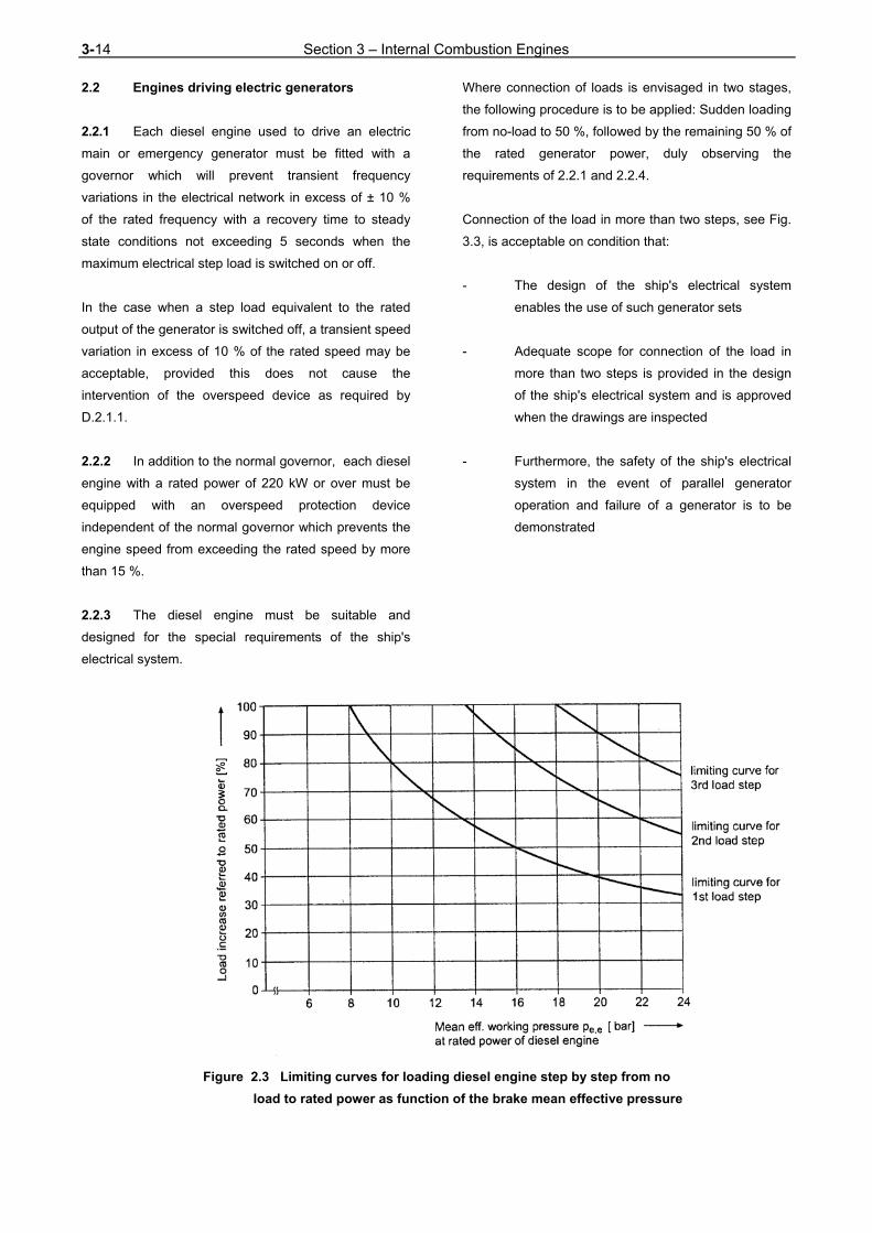
3-14 Section 3 – Internal Combustion Engines
2.2 Engines driving electric generators
2.2.1 Each diesel engine used to drive an electric
main or emergency generator must be fitted with a
governor which will prevent transient frequency
variations in the electrical network in excess of ± 10 %
of the rated frequency with a recovery time to steady
state conditions not exceeding 5 seconds when the
maximum electrical step load is switched on or off.
In the case when a step load equivalent to the rated
output of the generator is switched off, a transient speed
variation in excess of 10 % of the rated speed may be
acceptable, provided this does not cause the
intervention of the overspeed device as required by
D.2.1.1.
2.2.2 In addition to the normal governor, each diesel
engine with a rated power of 220 kW or over must be
equipped with an overspeed protection device
independent of the normal governor which prevents the
engine speed from exceeding the rated speed by more
than 15 %.
2.2.3 The diesel engine must be suitable and
designed for the special requirements of the ship's
electrical system.
Where connection of loads is envisaged in two stages,
the following procedure is to be applied: Sudden loading
from no-load to 50 %, followed by the remaining 50 % of
the rated generator power, duly observing the
requirements of 2.2.1 and 2.2.4.
Connection of the load in more than two steps, see Fig.
3.3, is acceptable on condition that:
- The design of the ship's electrical system
enables the use of such generator sets
- Adequate scope for connection of the load in
more than two steps is provided in the design
of the ship's electrical system and is approved
when the drawings are inspected
- Furthermore, the safety of the ship's electrical
system in the event of parallel generator
operation and failure of a generator is to be
demonstrated
Figure 2.3 Limiting curves for loading diesel engine step by step from no
load to rated power as function of the brake mean effective pressure
Section 3– Internal Combustion Engines 3-15
2.2.4 Speed must be stabilized and in steady-state
condition within five seconds, inside the permissible
range for the permanent speed variation δr.
The steady-state condition is considered to have been
reached when the residual speed variation does not
exceed ± 1 % of the speed associated with the set
power.
2.2.5 The characteristic curves of the governors of
diesel engines of generator sets operating in parallel
must not exhibit deviations larger than those specified in
Chapter 105 - Electrical Installations, Section 1, F.1.
2.2.6 Generator sets which are installed to serve
stand-by circuits must satisfy the stand-by function even
when the engine is cold. The start-up and loading
sequence is to be concluded in about 30 seconds.
2.2.7 Emergency generator sets must satisfy the
above governor conditions also unlimited with the start-
up and loading sequence having to be concluded in
about 45 seconds.
2.2.8 The governors of the engines mentioned in 2.2
must enable the rated speed to be adjusted over the
entire power range with a maximum deviation of 5 %.
2.2.9 The rate of speed variation of the adjusting
mechanisms must permit satisfactory synchronization in
a sufficiently short time. The speed characteristic should
be as linear as possible over the whole power range.
The permanent deviation from the theoretical linearity of
the speed characteristic may, in the case of generating
sets intended for parallel operation, in no range exceed
1 % of the rated speed.
Notes relating to 2.1 and 2.2:
a) The rated power and the corresponding rated speed
relate to the conditions under which the engines are
operated in the system concerned.
b) An independent overspeed protection device
means a system all of whose component parts,
including the drive, work independently of the
normal governor.
2.3 Use of electrical/electronic governors
2.3.1 The governor and the associated actuator must,
for controlling the respective engine, be suitable for the
operating conditions laid down in the Construction Rules
and for the requirements specified by the engine
manufacturer. For single propulsion drives it has to be
ensured that in case of a failure of the governor or
actuator the control of the engine can be taken over by
another control device.
The regulating conditions required for each individual
application as described in 2.1 and 2.2 are to be
satisfied by the governor system.
Electronic governors and the associated actuators are
subject to type testing.
For the power supply, see Chapter 105 - Electrical
Installations.
2.3.2 Requirements applying to main engines
For propulsion installations, to ensure continuous speed
control or immediate resumption of control after a fault,
at least one of the following requirements is to be
satisfied:
- the governor system has an independent back-
up system
- there is a redundant governor assembly for
manual change-over with a separately
protected power supply
- a complete preset governor assembly is
available as a spare
- the engine has a manually operated fuel
admission control system suitable for
manoeuvring
In the event of a fault in the governor system, the
operating condition of the engine must not become
dangerous, that is, the engine speed and power must
not increase.
Alarms to indicate faults in the governor system are to
be fitted.
3-16 Section 3 – Internal Combustion Engines
2.3.3 Requirements applying to auxiliary engines
for driving generators
Each auxiliary engine must be equipped with its own
governor system.
In the event of a fault in the governor system, the fuel
admission in the injection pumps must be set to "0".
Alarms to indicate faults in the governor system are to
be fitted.
2.3.4 The special conditions necessary to start
operation from the dead ship condition are to be
observed, see Chapter 105 - Electrical Installations,
Section 7, D.
3. Cylinder overpressure warning device
3.1 All the cylinders of engines with a cylinder bore
of > 230 mm are to be fitted with cylinder over pressure
control valves. The response threshold of these valves
shall be set at not more than 40 % above the
combustion pressure at the rated power.
3.2 The cylinder overpressure control valves may
be replaced by effective combined visual/acoustic
cylinder overpressure warning devices. These must
have been type-tested by TL.
4. Crankcase airing and venting
4.1 Crankcase airing
The airing of crankcases is not allowed.
4.2 Crankcase venting
4.2.1 Where crankcase venting systems are
provided their clear opening is to be dimensioned as
small as possible.
4.2.2 Where provision has been made for extracting
the lubricating oil vapours, e.g. for monitoring the oil
vapour concentration, the negative pressure in the
crankcase may not exceed 2,5 mbar.
4.2.3 The vent pipes of two or more engines must
not be combined.
5. Crankcase safety devices
5.1 Crankcase safety devices have to be type
approved.
5.2 Safety valves to safeguard against
overpressure in the crankcase are to be fitted to all
engines with a cylinder bore of > 200 mm and/or a
crankcase volume of ≥ 0,6 m3.
All other spaces communicating with the crankcase, e.g.
gear or chain casings for camshafts or similar drives,
are to be equipped with additional safety devices if the
volume of these spaces exceeds 0,6 m3.
5.3 Engines with a cylinder bore of > 200 mm and
≤ 250 mm must be equipped with at least one safety
valve at each end of the crankcase. If the crankshaft
has more than 8 throws, an additional safety valve is to
be fitted near the middle of the crankcase.
Engines with a cylinder bore of > 250 mm and ≤ 300
mm must have at least one safety valve close to every
second crank throw, subject to a minimum number of
two.
Engines with a cylinder bore of > 300 mm must have at
least one safety valve close to each crank throw.
5.4 Each safety valve must have a free cross-
sectional area of at least 45 cm2.
The total free cross-sectional area of the safety valves
fitted to an engine to safeguard against overpressure in
the crankcase may not be less than 115 cm2/m3 of
crankcase volume.
Notes relating to 5.2 and 5.4
a) In estimating the gross volume of the crankcase, the
volume of the fixed parts which it contains may be
deducted.
b) A space communicating with the crankcase via a
total free cross-sectional area of > 115 cm2/m3 of
volume need not be considered as a separate space.
In calculating the total free cross-sectional area,
individual sections of < 45 cm2 are to be
disregarded.
Section 3– Internal Combustion Engines 3-17
c) Each safety valve required may be replaced by not
more than two safety valves of smaller cross-
sectional area provided that the free cross-sectional
area of each safety valve is not less than 45 cm2.
5.5 The safety devices must take the form of flaps
or valves of proven design. In service they must be
oiltight when closed and must prevent air from flowing
into the crankcase. The gas flow caused by the
response of the safety device must be deflected, e. g.
by means of a baffle plate, in such a way as not to
endanger persons standing nearby.
Safety devices shall respond to as low an overpressure
in the crankcase as possible (maximum 0,2 bar).
5.6 Crankcase doors and their fittings must be so
dimensioned as not to suffer permanent deformation
due to the overpressure occurring during the response
of the safety equipment.
5.7 A warning sign is to be mounted on the local
engine control platform or, if appropriate, on both sides
of the engine drawing attention to the fact that the
crankcase doors and/or sight holes may not be opened
immediately following stoppage of the engine, but only
after a sufficient cooling period has elapsed.
6. Safety devices in the lubricating oil system
Each engine with a rated power of 220 kW or over is to
be fitted with devices which automatically shut down the
engine in the event of failure of the lubricating oil supply.
Exceptions to this rule are engines driving emergency
generator sets and emergency fire pumps. For these
engines an alarm has to be provided.
G. Auxiliary Systems
1. General
Peripheral piping systems and filter arrangements see
Chapter 107 - Ship Operation Installations and Auxiliary
Systems, Section 8.
2. Fuel lines
2.1 General
2.1.1 Only pipe connections with metal sealing
surfaces or equivalent pipe connections of approved
design may be used for fuel injection lines.
2.1.2 Feed and return lines are to be designed in
such a way that no unacceptable pressure surges occur
in the fuel supply system. Where necessary, the
engines are to be fitted with surge dampers approved
by TL.
2.1.3 Oil fuel lines are not to be located immediately
above or near units of high temperature steam
pipelines, exhaust manifolds, silencers or other
equipment required to be insulated according to G.7. As
far as practicable, oil fuel lines are to be arranged far
apart from hot surfaces, electrical installations or other
sources of ignition and are to be screened or otherwise
suitably protected to avoid oil spray or oil leakage onto
the sources of ignition. The number of joints in such
piping system are to be kept to a minimum.
2.2 Shielding
2.2.1 Regardless of the intended use and location of
internal combustion engines, all external fuel injection
lines (high pressure lines between injection pumps
and injection valves) are to be shielded by jacket pipes
in such a way that any leaking fuel is:
- Safely collected
- Drained away unpressurized
- Efficiently monitored
2.2.2 If pressure variations of > 20 bar occur in fuel
feed and return lines, these lines are also to be
shielded.
2.2.3 The high pressure fuel pipe and the outer
jacket pipe have to be of permanent assembly.
3-18 Section 3 – Internal Combustion Engines
2.2.4 Where pipe sheaths in the form of hoses are
provided as shielding, the hoses must be demonstrably
suitable for this purpose and approved by TL.
2.3 Fuel leak drainage
Appropriate design measures are to be introduced to
ensure generally that leaking fuel is drained efficiently
and cannot enter into the engine lube oil system.
2.4 Heat tracing, thermal insulation,
re-circulation
Fuel lines, including fuel injection lines, to engines
which are operated with preheated fuel are to be
insulated against heat losses and, as far as necessary,
provided with heat tracing.
Means of fuel circulation are also to be provided.
3. Filter arrangements
3.1 The requirements for the fuel and lubricating oil
filter equipment of motors are defined in Chapter 107 -
Ship Operation Installations and Auxiliary Systems,
Section 8.
3.2 Fuel and lubricating oil filters which are to be
mounted directly on the engine are not to be located
above rotating parts or in the immediate proximity of hot
components.
3.3 Where the arrangement stated in 3.1 is not
feasible, the rotating parts and the hot components are
to be sufficiently shielded.
3.4 Filters have to be so arranged that fluid
residues can be collected by adequate means. The
same applies to lubricating oil filters if oil can escape
when the filter is opened.
3.5 Oil filters fitted parallel for the purpose of
enabling cleaning without disturbing oil supply to
engines (e.g. duplex filters) are to be provided with
arrangements that will minimize the possibility of a filter
under pressure being opened by mistake. Filters/filter
chambers shall be provided with suitable means for:
- Venting when put into operation
- Depressurizing before being opened
Valves or cocks with drain pipes led to a safe location
shall be used for this purpose.
4. Lubricating oil system
4.1 General requirements relating to lubricating oil
systems and to the cleaning, cooling etc. of the
lubricating oil are contained in Chapter 107 - Ship
Operation Installations and Auxiliary Systems, Section
8, І. For piping arrangement 2.1.3 is to be applied.
4.1.1 Engines which sumps serve as oil reservoirs
must be so equipped that the oil level can be
established and, if necessary, topped up during
operation. Means must be provided for completely
draining the oil sump.
4.1.2 The combination of the oil drainage lines from
the crankcases of two or more engines is not allowed.
4.2 The equipment of engines fitted with lubricating
oil pumps is subject to Chapter 107 - Ship Operation
Installations and Auxiliary Systems, Section 8, І.
4.2.1 Main lubricating oil pumps driven by the engine
are to be designed to maintain the supply of lubricating
oil over the entire operating range.
4.2.2 Main engines which drive main lubricating oil
pumps are to be equipped with independently driven
stand-by pumps.
4.2.3 In installations comprising more than one main
engine and with separate lubricating oil systems
approval may be given for the carriage on board of
reserve pumps ready for mounting provided that the
arrangement of the main lubricating oil pumps enables
the change to be made with the means available on
board.
4.2.4 Lubricating oil systems for cylinder lubrication
which are necessary for the operation of the engine and
which are equipped with electronic dosing units have to
be approved by TL.
Section 3– Internal Combustion Engines 3-19
5. Cooling system
5.1 For the equipment of engines with cooling
water pumps and for the design of cooling water
systems, see Chapter 107 - Ship Operation Installations
and Auxiliary Systems, Section 8, J. and K.
5.1.1 Main cooling water pumps driven by the engine
are to be designed to maintain the supply of cooling
water over the entire operating range.
5.1.2 Main engines which drive main cooling water
pumps are to be equipped with independently driven
stand-by pumps or with means for connecting the
cooling water system to independently driven stand-by
pumps.
5.1.3 In installations comprising more than one main
engine and with separate fresh cooling water systems
approval may be given for the carriage on board of
reserve pumps ready for mounting provided that the
arrangement of the main fresh cooling water pumps
enables the change to be made with the means
available on board. Shutoff valves must be provided
enabling the main pumps to be isolated from the fresh
cooling water system.
5.2 If cooling air is drawn from the engine room,
the design of the cooling system is to be based on a
room temperature of at least 45 °C.
The exhaust air of air-cooled engines may not cause
any unacceptable heating of the spaces in which the
plant is installed. The exhaust air is normally to be led to
the open air through special ducts.
5.3 Where engines are installed in spaces in
which oil-firing equipment is operated, Chapter 107 -
Ship Operation Installations and Auxiliary Systems,
Section 17, A.5. is also to be complied with.
6. Charge air system
6.1 Exhaust gas turbochargers
6.1.1 The construction and testing of exhaust gas
turbochargers are subject to Section 4.
6.1.2 Exhaust gas turbochargers may exhibit no
critical speed ranges over the entire operating range of
the engine.
6.1.3 The lubricating oil supply must also be ensured
during start-up and run-down of the exhaust gas
turbochargers.
6.1.4 Even at low engine speeds, main engines must
be supplied with charge air in a manner to ensure
reliable operating.
6.1.5 If, in the lower speed range or when used for
manoeuvring, an engine can be operated only with a
charge air blower driven independently of the engine, a
stand-by charge air blower is to be installed or an
equivalent device of approved design.
6.1.6 With main engines emergency operation must
be possible in the event of a turbocharger failure.
6.2 Charge air cooling
6.2.1 The construction and testing of charge air
coolers are subject to Chapter 107 – Ship Operation
Installations and Auxiliary Systems, Section 16.
6.2.2 Means are to be provided for regulating the
temperature of the charge air within the temperature
range specified by the engine manufacturer.
6.2.3 The charge air lines of engines with charge air
coolers are to be provided with sufficient means of
drainage.
7. Equipment for charge air and exhaust gas
lines
General rules relating to exhaust gas lines are
contained in Chapter 107 - Ship Operation Installations
and Auxiliary Systems, Section 8, M.
8. Starting Equipment
The relevant equipment is defined in Chapter 107 - Ship
Operation Installations and Auxiliary Systems, Section
6.
3-20 Section 3 – Internal Combustion Engines
H. Control Equipment
1. Main engines
1.1 Local control station
To provide emergency operation of the propulsion plant
a local control station is to be installed from which the
plant can be operated and monitored.
1.1.1 Indicators for the following parameters are to be
clearly sited on the local main engine control station:
- Speed/direction of rotation
- Lube oil pressure
- Fuel pressure
- Cylinder cooling water pressure
- Charge air pressure
- Starting air pressure
- Control air pressure
1.1.2 The following temperature indicators are to be
provided on the local control station or directly on the
engine:
- Lube oil inlet
- Cylinder cooling water outlet
- Charge air inlet, charge air cooler
- Charge air outlet, charge air cooler
- Fuel at engine inlet (for engines running on
heavy fuel only)
- Exhaust gas temperature
wherever the dimensions permit, at each
cylinder outlet and at the turbocharger
inlet/outlet
1.1.3 In the case of gear and controllable pitch
propeller systems, the local control indicators and
control equipment required for emergency operation are
to be installed.
1.1.4 Critical speed ranges are to be marked in red
on the tachometers.
1.2 Machinery control centre
If the naval ship has a control station for the propulsion
system with remote operation or control, the control
indicators listed in 1.1.1, 1.1.2 and 1.1.3 are to be
installed in this centre.
1.3 Bridge/navigation centre
1.3.1 The essential operating parameters for the
propulsion system are to be provided in the control
station area.
1.3.2 The following stand-alone control equipment is
to be installed:
- Speed/direction of rotation of main engine
- Speed/direction of rotation of shafting
- Propeller pitch (controllable pitch propeller)
Another scope of control equipment may be agreed
between Naval Authority, shipyard and TL.
1.3.3 In the case of engine installations up to a total
output of 600 kW, simplifications can be agreed with
TL.
2. Auxiliary engines
As a minimum requirement the following controls are to
be clearly located on the engine:
- Lube oil pressure
- Fuel pressure
- Cylinder cooling water pressure

Section 3– Internal Combustion Engines 3-21
- Cylinder cooling water temperature (outlet)
- Fuel temperature at engine inlet (for engines
running on heavy fuel oil only)
A different scope of controls to be agreed between
Naval Authority, shipyard and TL.
I. Alarms
1. General
1.1 The following Rules apply to machinery
installations which have been designed for conven-
tional operation without any degree of automation.
1.2 Within the context of these Rules, the word
alarm is understood to mean the visual and audible
warning of abnormal operating parameters.
2. Scope of alarms
Alarms are to be fitted to signal that the following
limiting values are being exceeded:
2.1 Main engines
2.1.1 Lower limiting value
- Lube oil pressure
- Cylinder cooling water pressure
- Piston coolant pressure
- Starting air pressure
- Control air pressure
2.1.2 Upper temperature limit
- Lube oil inlet
- Cylinder cooling water outlet
- Piston coolant outlet
- Charge air outlet, charge air cooler
- Exhaust gas (exhaust-gas turbocharger outlet)
2.2 Auxiliary engines
Lower limit:
- Lube oil pressure
- Cylinder cooling water pressure or flow
J. Engine Alignment/Seating
1. Engines are to be mounted and secured to
their foundations in conformity with Guidelines for the
Seating of Propulsion Plants.
2. If elastomer bearing elements are used,
engines on elastic mountings may only be aligned after
settling.
Supply equipment, couplings and compensators have to
be adjusted to the respective bearing.
Casting resin bearings have to be built up only in
presence of a TL Surveyor by companies approved for
this type of work. Only approved casting resins are to be
used. The installation guidelines of the resin producer
have to be observed.
3. The crankshaft alignment is to be checked
every time an engine has been aligned on its founda-
tion by measurement of the crank web deflectionand/or
other suitable means.
Note is to be taken of:
- The draught/load condition of the vessel
- The condition of the engine - cold/
preheated/hot
4. Where the engine manufacturer has not
specified values for the permissible crank web
deflection, assessment is to be based on TL's reference
values.
Section 4 – Thermal Turbomachinery 4-1
SECTION 4
THERMAL TURBOMACHINERY
A. General 1. Scope
The following Rules apply to main and auxiliary gas
turbines and, where appropriate, to exhaust gas turbo-
chargers.
TL reserve the right to authorize deviations from the
Rules in the case of low-power turbines and exhaust
gas turbochargers.
2. Documents for approval
For every gas turbine installation, the documents listed
below under a) to f) are to be submitted to TL in
triplicate for approval:
a) Assembly and sectional drawings
b) Detail drawings of rotors, casings, blades,
combustion chambers and heat exchangers
c) Diagrammatic layout of the fuel system,
including control and safety devices, and of
the lubricating oil system
d) Start-up equipment with system description
e) Details of operating conditions, including
the pressure and temperature curves in the
turbine and compressor at the rated power
and corresponding rotational speeds, and
details of permissible temporary operation
beyond the values for the rated power
f) Proof, by calculation or some other method,
e.g. in the form of the results of burst tests
performed on turbine and compressor wheels,
that a sufficient safety margin has been
provided for in the components subject to the
severest loads. In the case of turbine guide
vanes and blades as well as turbine discs,
the service life on which the calculations were
based is to be specified together with the
temperatures occurring in the materials at
the rated power.
g) Details of the welding conditions for
welded components
h) Testing procedure
A set of operating instructions for each turbine type
has to be submitted.
In individual cases, according to the design and
purpose of the equipment, TL reserve the right to call for
additional documentation.
B. Materials
1. Approved materials
Gas turbine materials must fulfill the requirements
imposed by the operating conditions on the individual
engine components. In the choice of materials,
account is to be taken of such effects as, for example,
creep, thermal fatigue, oxidation and corrosion to
which parts are subject when in service. Evidence of
the suitability of the materials used is to be supplied to
TL in the form of details of their chemical and
mechanical properties and of the heat treatment
applied. Where composite materials are used, their
method of manufacture is to be described.
For the combustion air pipes steel or another non-
combustible material has to be used. Elastic

4-2 Section 4 – Thermal Turbomachinery
connections have to be non-flammable.
As material for exhaust gas pipes heat-resistant steel
has to be used. The choice of the steel type has to
consider the operation temperatures and the corrosion
resistance, see also DIN 86009.
Pipes and fittings are to be manufactured from stainless
steel.
2. Testing of materials
The materials of shafts, turbine and compressor
wheels, guide vanes and blades, turbine and
compressor casings, combustion chambers and heat
exchangers are to be tested under TL's supervision or
according to the manufacturer's test specification
accepted by TL in scope of the manufacturer's approval.
For material tests of turbochargers see also the TL
Rules Guidelines for the Testing of Exhaust Gas
Turbochargers.
C. Design and Construction Principles
1. General data
1.1 Standards
For the design of propulsion plants which are
equipped with gas turbines Table 4.1 has to be
considered.
Table 4.1 Standards for gas turbines
Standards Title of standard
DIN 4340 Definitions, designations
DIN 4341 Part 1: Regulations for commissioning of
gas turbines
DIN 4342 Standard reference conditions, standard
performance
1.2 Data concerning operation parameters have to
be defined.
1.3 Operational diagram to be provided.
1.4 The family of gas turbine characteristics has
to be defined, with the rated driving power P shown as a
function of the speeds of gas generator and the effective
power turbine.
1.5 Measures for planned preventive mainte-
nance are to be defined.
1.6 The connection between effective power
shaft of the gas turbine and the gear has to be defined
together with the manufacturer of the gas turbine. The
manufacturer has to provide a guideline for the
alignment with a definition of the permissible tolerances.
Note
The theoretical time between two overhauls should be at least
6 000 operating hours for the gas generator and at least 10
000 operating hours for the performance part of the gas
turbine. Variations for different operating conditions are to
be defined by the manufacturer. Basis of operation is the
relation of performance and operating hours of the naval ship
defined by the Naval Authority.
2. Foundation
The foundations of geared turbine installations are to
be so designed and constructed that only minor relative
movements can occur between the turbine and the
gearing which can be compensated by suitable cou-
plings.
3. Air supply and exhaust gas installations
3.1 General design requirements
The air intake ducting is to be equipped to prevent
extraneous substances from entering the compressor
and turbine. In particular, measures are to be taken to
reduce sufficiently the salinity of the combustion air.
Cleaning equipment is to be provided to remove
deposits from compressors and turbines.
The way of cleaning (dry or humid) and the frequency of
cleaning as well as the substances to be used have to
be agreed with the manufacturer and are to be defined
in the building specification.

Section 4 – Thermal Turbomachinery 4-3
After the cleaning procedure it must be possible to
remove the cleaning substances.
The design and arrangement of the ducts for
combustion air and exhaust gas must be in
accordance with the guidelines of the turbine
manufacturer. These ducts have to be so dimensioned
and shaped that the pressure loss permitted by the
turbine manufacturer is not exceeded. By using elastic
connection pieces the transfer of vibrations and
structure-borne sound from the gas turbine to the pipe
system shall be avoided. The influence of thermal
expansion has to be observed.
Measures are to be taken that the maximum airborne
sound level prescribed by the Naval Authority will not be
exceeded.
Changes of the sections of combustion air and exhaust
gas ducts shall not exceed an angle to the axis of more
than 5°.
3.2 Combustion air ducts
The combustion air has to be sucked in from outside
considering the following requirements:
- For NBC protected ships the requirements
defined by the Naval Authority have to be met.
- If the draught air ducts can be closed, a
control device and a start blockage have to be
provided.
- Each gas turbine must have its own
combustion air duct.
- The openings for sucking in have to be
arranged and protected in a way that foreign
matters as well as spray and swell water
cannot penetrate into the duct system. It has to
be avoided that exhaust gases are sucked in.
The application of jalousies, air filters, water
separators, water traps, etc. is to be defined
in the building specification. The requirements
of the gas turbine manufacturer for the
combustion air have to be met.
- The entrance openings for the combustion air
ducts have to be covered by a coarse mesh
screen.
- The combustion air ducts have to be of such a
stiff design that the pumping of the compressor
does not lead to damages.
- The combustion air ducts have to be equipped
with dampers controlled by low pressure, which
are opening if the air filter devices are blocked,
e.g. by icing, impurities. The permissible
pressure difference to start with the use of the
bypass has to be defined in the building
specification.
3.3 Exhaust gas ducts
The exhaust gas duct of each gas turbine has to be led
to the open. The outlet nozzle has to be arranged in a
way that neither personnel is endangered nor
equipment will be harmed.
Exhaust gas ducts and silencers have to be equipped
with non-combustible insulation material, which is free
of asbestos and with a covering.
Devices for the closing of the exhaust outlet have to
be provided. If the covers are removable, possibilities
for storage and mounting have to be foreseen. If
exhaust gas flaps are remote controlled a control device,
starting blockage and an automatic shut down of the
gas turbine in case of flap closing have to be provided.
The position of the flaps has to be indicated.
If exhaust gas ducts end near the design waterline
measures have to be taken that in no case water gets
into the gas turbine.
The exhaust gas ducts have to be equipped with
drainage and cleaning openings.
4. Combustion chambers
Access to the combustion chambers must be ensured.
It shall be possible to inspect the burner cans without
having to remove the gas generator.

4-4 Section 4 – Thermal Turbomachinery
5. Bearing lubrication
5.1 Bearing lubrication may not be impaired by
hot gases or by adjacent hot components.
General requirements for lubrication oil equipment are
given in Chapter 107 - Ship Operation Installations and
Auxiliary Systems, Section 8, І.
Each gas turbine must be equipped with its own,
independent lubrication system.
5.2 The lubrication equipment of a gas turbine is
to be arranged and protected in a way, that in case of
leakage the lubricating oil cannot reach rotating parts or
surfaces with a temperature above 220 °C.
The lubricating oil system has to be equipped with a
filter device, for which cleaning is possible without
stopping the turbine. An exceeding of the maximum
permissible pressure difference in the filter has to be
indicated. During operation a check of the oil reserves
must be possible. At a location which is good accessible
a device to take oil samples from the oil circuit has to be
provided. Care has to be taken that lubrication oil can
be added during operation of the gas turbine.
5.3 The cooling back of lubrication oil has to be
performed by oil, possibly from the transmission gear.
Otherwise the compatibility of the material of the heat
exchanger with the lubricating oil and the cooling
liquid has to be proven.
6. Start-up equipment 6.1 Gas turbines are to be fitted with start
equipment enabling them to be started up from the
"shut down" condition.
The type of the starting equipment has to be defined in
the building specification. A preheating of the operation
substances (oil, fuel) is permissible.
Up to six subsequent starting procedures must be
possible. A start in the hot condition, e.g. after an
emergency stop, has to be enabled. If a waiting time is
prescribed, the starting blockage must be releasable in
an emergency case.
In case of a wrong starting procedure the injected fuel
must be drained. A new start may not delayed because
of this by more than 60 seconds.
6.2 A starting device with compressed air is to be
designed according to Chapter 107 - Ship
Operation Installations and Auxiliary Systems,
Section 6. For hydraulic starting devices the
requirements of Chapter 107, Section 14 and for
electrical devices the data defined in Chapter 105 -
Electrical Installations apply.
Where, in case of several gas turbines, the possibility
exists to use bleeding compressed air from an already
operating compressor/turbine unit, the connections for
bleeding compressed air are to be linked with the
compressed air starting system.
6.3 For the cleaning of the gas turbine and the
fuel system an operation without ignition must be
possible in several cycles. Number and length of the
cycles as well as the needed speed have to be defined
by the manufacturer.
7. Turning gear
Main propulsion turbines are to be equipped with
turning gear.
The rotors of auxiliary turbines must at least be capable
of being turned by hand.
8. Connections
Pipes are to be connected in such a way that no
unacceptable high forces or moments are transmitted to
the gas turbine.
The fuel equipment of a gas turbine is to be arranged
and protected in a way, that in case of leakage fuel
cannot reach rotating parts or surfaces with a
temperature above 220 °C. The installation and
mounting of the fuel piping has to be executed in a way
that no damage caused by vibrations may occur.
9. Fuel
9.1 TL is to be informed of the fuel grade
authorized by the turbine manufacturer and of the

Section 4 – Thermal Turbomachinery 4-5
equipment needed for treating the fuel. 9.2 The installation of fuel cleaning devices like
filters, separators, water traps, etc. has to be defined in
the building specification. The requirements of the gas
turbine manufacturer concerning the fuel have to be
met. Requirements for the fuel system which are not
directly related to the gas turbine are given in Chap-
ter 107 - Ship Operation Installations and Auxiliary
Systems, Section 8, G.
9.3 Type and scope of the fuel transfer from the
storage tank to the gas turbine have to be arranged
according to the requirements of the gas turbine
manufacturer and shall be defined in the building
specification.
10. Vibrations / acoustic capsule
10.1 The range of service speeds may not give rise
to unacceptable bending vibrations or to vibrations
affecting the entire installation (1). 10.2 If NBC protection of the machinery rooms is
demanded, a pressure which is lower than in the
machinery room by at least 0,5 hPa (0,5 mbar) has to
be established in the sound protection capsule, see
also Chapter 107 - Ship Operation Installations and
Auxiliary Systems, Section 11.
If a separate suction duct is foreseen for the cooling
air of the sound protection capsule, such a duct has to
be equipped with a water separator. The required
degree of cleanliness of the air as well as the needed
cooling volume has to be defined in the building
specification in accordance with the manufacturer. In
case of cooling failure it must be ensured that no
overheating of the gas turbine happens. The necessary
reduction of performance has to be defined in the
building specification.
(1) The assessment of vibrations may be based on ISO
10816-3 "Mechanical vibration - Evaluation of machine
vibration by measurements on non-rotating parts" or an
equivalent standard.
If a cooling after the operation is required, the cooling
system must be able to work independently from the
gas turbine. The time period for the cooling and the
created quantity of heat have to be defined by the
manufacturer of the gas turbine.
10.3 If gas turbines are installed in machinery
rooms without sound protection capsules, measures are
to be taken that the defined room temperature will not
be exceeded. It must be ensured that other aggregates
and devices which are installed in the same machinery
room are not harmed.
11. Inspection openings
It is recommended that inspection openings be
provided which allow the inside of the gas turbine and
compressor to be inspected with special equipment,
e.g. a borescope or similar, without the need for
dismantling.
D. Emergency Operation
1. In multi-shaft installations, the failure of one
shaft must not hinder the continued, independent
operation of the remaining units. 2. In single-shaft installations with two or more
main gas turbines, care is to be taken to ensure that, in
the event of one of the gas turbines failing, the others
are able to continue operation independently.
3. In the case of single-shaft installations with
only one main gas turbine, special agreement is to be
reached with TL concerning the emergency operating
equipment.
E. Control and Safety Equipment 1. Control equipment
1.1 Gas turbines for main propulsion machinery
equipped with controllable pitch propellers, disengaging
couplings or an electrical transmission system are to be
fitted with a speed governor which, in the event of a
sudden loss of load, prevents the revolutions from
increasing to the trip speed.
4-6 Section 4 – Thermal Turbomachinery
1.2 The speed increase of gas turbines driving
electric generators - except those for electrical propeller
drive - resulting from a change from full load to no load
may not exceed 5 % on the resumption of steady
running conditions. The transient speed increase
resulting from a sudden change from full load to no-load
conditions may not exceed 10 % and must be
separated by a sufficient margin from the trip speed.
2. Safety devices
2.1 Gas turbines are to be equipped with a quick-
closing device which automatically shuts off the fuel
supply to the turbine in case of:
- Overspeed of the power turbine. Speeds
exceeding the rated value by more than 15 %
are to be prevented.
- An unacceptable drop in the lubricating oil
pressure
- Loss of flame during operation
- Excess of temperature limits in compartments
2.2 Start-up must take place automatically in the
prescribed sequence. Interlocks must be provided to
ensure that this sequence (attainment of ignition
speed, ignition, flame monitoring) is followed.
2.3 Equipment is to be provided which will actuate
an alarm if:
- The maximum permissible gas temperature at
the gas generator outlet is exceeded
- The lubricating oil temperature in the turbine
bearings rises excessively
- Excess of permissible temperature in
compartments
In case of exceeded gas temperature, the alarm shall
actuate a "Reduce output" signal, unless such a
reduction is effected automatically.
The provision of an alarm system which responds to
excessive vibration velocities is recommended.
2.4 Subject to the agreement of TL the extent of
the quick-closing and alarm equipment of low-power
gas turbines may be reduced.
2.5 Each gas turbine has to be equipped with a
stop mechanism, which shuts off automatically if:
- The maximum speed of gas generator or
effective performance turbine is exceeded - Inadmissible vibrations occur - The minimum oil pressure falls short - The maximum entrance temperature of the
effective performance turbine is exceeded
- The flame is interrupted during the operation
The stopping shall be possible manually and by
remote control. The manual stopping must be possible
directly at the gas turbine. Suitable operating devices
have to be provided at a good accessible position.
F. Monitoring Equipment 1. Arrangement
The necessary control and monitoring equipment for
each main propulsion unit is to be located on the control
platform.
2. Scope of the monitoring equipment 2.1 Monitoring equipment is to be provided for
those data the reading and/or recording of which is
necessary for the reliable control of operations. The
following monitoring equipment is to be provided as a
minimum:
- Air pressure and temperature at compressor
inlet
- Gas pressure and temperature at gas
generator outlet
- Lubricating oil pressure and temperature

Section 4 – Thermal Turbomachinery 4-7
- Gas generator and power turbine rotor speeds
Equipment is to be provided for periodically recording the
temperature at the gas generator outlet.
2.2 For all equipment of control, operating and
watch stands and centres the requirements of
Chapter 106 - Automation, especially Section 1 have
to be applied. The total scope of the operating and
control equipment has to be defined in the building
specification.
2.3 Automation shall be used to simplify
operation and control and exclude operational
mistakes by an automatic initiation of operation
procedures depending inevitably from each other. In
addition automation shall enable a centralised handling
and control of the propulsion plant. The equipment for
local manual handling and control has to exist to a full
extent independently from the degree of automation.
The procedures to prepare the ship for sea shall not be
included in the automation.
In case of failure of the energy supply for the automation
equipment it must be ensured that the devices remain
in the adjusted operational position or, if necessary, are
changing into a position not harming the actual
operation. For this see also the requirements in Chapter
106 - Automation, Section 1.
2.4 The telemetric transfer of parameters of the
machinery plant shall be done only by a separate
transfer system.
The equipment for operating and control must ensure
a safe operation directly at the gas turbine and also by
remote control. All parameters which are important for
a regular operation must be indicated directly at the
turbine. These indicating instruments shall be put
together in an auxiliary control stand, as far as possible.
The safety system must work independently from the
gas turbine control. In the case of activation of a safety
device, the gas turbine must be blocked against a new
start. The devices for deblocking have to be arranged
in a way which enables a quick start of the gas turbine
again.
G. Maintenance
1. Maintenance schedule
A schedule is to be submitted to TL specifying the
maintenance operations to be carried out on gas
turbines together with the intervals between such
operations.
H. Tests
1. Scope of tests
1.1 Non-destructive testing
The scope of the non-destructive tests to be performed
on rotating parts and casings is to be agreed with TL.
1.2 Balancing
Gas turbine and compressor rotors are to be balanced
when in the condition ready for assembly.
1.3 Cold overspeed test
Turbine and compressor wheels are to be tested at a
speed at least 15 % above the rated speed for not less
than three minutes.
Turbine and compressor wheels of exhaust gas turbo-
chargers are to be tested at a speed 20 % above the
maximum working speed for at least three minutes.
TL may accept mathematical proof of the stresses in
the rotating parts at overspeed as a substitute for the
overspeed test itself provided that the design is such
that reliable calculations are possible and the rotating
parts have been subjected to thorough non-destructive
testing to ascertain their freedom from defects.
1.4 Pressure and tightness tests
Finished casing parts and heat exchangers are to be
subjected to hydrostatic testing at 1,5 times the
maximum permissible working pressure peperm. If it is
demonstrated by other means that the strength of
casing parts is sufficient, a tightness test at 1,1 times
the maximum permissible working pressure will suffice.

4-8 Section 4 – Thermal Turbomachinery
Exhaust gas turbocharger spaces containing cooling
water are to be tested at a pressure pp of 4 bar, subject
to a minimum of 1,5 pe,perm
pp = Test pressure [bar]
pe,perm = Maximum permissible working pressure in
the part concerned [bar]
I. Trials
1. Factory trials
1.1 Gas turbines are to be subjected at the factory
to a trial run carried out, wherever possible, at the
service temperature.
The satisfactory operation of the safety and control
equipment is to be demonstrated during the trial run.
1.2 Exhaust gas turbochargers are to be tested for
20 minutes at the maximum working speed and at
working temperature.
2. Shipboard trials
2.1 Main turbines are to be subjected to a dock
trial and thereafter a trial voyage on the basis of test
program agreed by TL containing following tests:
- Endurance test at nominal
- Speed start-up manoeuvres
TL reserve the right to call for additional tests in
individual cases.
2.2 Turbines driving electric generators or
auxiliary machines are to be run for at least 1 hour at
their rated power and for 30 minutes at 110 % rated
power.

Section 5 – Main Shafting 5-1
SECTION 5
MAIN SHAFTING A. General
1. Scope
1.1 The following Rules apply to standard and
proven designs of main shafting. Designs deviating
from standard and proven type require special
approval by TL. 1.2 For difficult or special operating conditions
adequate reinforcements have to be provided.
1.3 TL reserve the right to call for propeller shaft
dimensions in excess of those specified in this Section if
the propeller arrangement results in increased bending
stresses.
1.4 In case of ships with ice classes, the
strengthening factors given in Section 9 are to be
complied with.
2. Documents for approval 2.1 The following drawings are to be
submitted in triplicate, all calculations and supporting
documentation in one copy for approval:
- Arrangement of the complete propulsion plant
- Detailed drawings and material data for all
torque transmitting components, especially
shafts and couplings
- Arrangement of the shaft bearings
- Arrangement and detail drawings of the stern
tube as well as bush bearings including stern
tube sealing and the corresponding lubricating
oil system.
- Calculation of the shaft alignment considering
all static and dynamic external forces acting on
the shaft during operation (e.g. weight of
couplings, propeller weight and propeller
forces, toothing forces of gears, etc.)
- Calculation of torsional vibrations
- In special cases separate bending vibration
calculations may be required
- For cast resin foundation of bearings (thrust,
radial including stern tube): arrangement and
design of the adapting pieces and bolts
The submitted documentation must contain all
required technical data to enable re-calculation of the
involved stresses.
B. Materials
1. Approved materials
1.1 Propeller, intermediate and thrust shafts
together with flange and clamp connections are to be
made of forged steel; as far as applicable, couplings
may be made of cast steel. 1.2 If the main shafting is manufactured of non
magnetic copper based materials, special approval
procedure may be requested.
1.3 For shafts made of fibre reinforced plastics
the TL Material Rules - Fibre Reinforced Plastics and
Bonding, are applicable.

5-2 Section 5 – Main Shafting
2. Testing of materials
2.1 All components of the shafting which are
transmitting and are therefore exposed to the torque
for the ship's propulsion are subject to the TL Mate-
rial Rules, and must be tested. This requirement is also
applicable for metal propeller shaft liners. 2.2 The application technique and the materials
used for protection of plastic coatings for propeller
shafts running in water must be approved by TL.
C. Shaft Dimensions
1. General 1.1 All parts of the shafting are to be
dimensioned in accordance with the following formulae
and in compliance with the requirements relating to
torsional vibrations set out in Section 8. The
dimensioning of the shafting shall be based on the total
rated installed power.
1.2 Materials
In general, the nominal tensile strength of steels Rm
used for shafting shall be between 400 N/mm2 and
800 N/mm2. The value of Rm used for calculation of the
material factor CW, see 3. in accordance with formula (2)
shall not be greater than:
- 600 N/mm2 for carbon and unalloyed steels
- 800 N/mm2 for liquid quenched and tempered
structural steels and stainless
austenitic steels, see TL Rules
Chapter 103 -Special Materials for
Naval Ships, Section 4 or duplex
steels
2. Shaft geometry
Where the geometry of a part is such that it cannot be
dimensioned in accordance with the following formulae,
alternative designs may be approved. For that special
evidence of the mechanical strength of the part or parts
has to be proven by adequate calculation methods
such as to DIN 743 (part 1 - 3): "Shafts and axles,
calculation of load capacity". In such cases complete
calculations based on the applied standard must be
submitted to TL for approval.
3. Minimum diameter
The minimum shaft diameter is to be determined by
applying formula (1).
C
d
d - 1n
P k F dd3
W
a
i4
Wa
(1)
d = Required outside diameter of shaft, [mm]
di = Inner d of shaft [mm], when applicable. If the
bore in the shaft is ≤ 0,4 · d, the expression,
d
d - 1a
i4
may be set to 1,0
da = Actual outer diameter shaft [mm]
Pw = Rated power of driving motor [kW]
n = Shaft speed, [min-1]
F = Factor for the type of propulsion installation [-]
a) Intermediate and thrust shafts
= 95 for turbine installations,
engine installations with
slip/hydraulic couplings and
electric propulsion
installations,
= 100 for all other propulsion
installations,
b) Propeller shafts,
= 100 for all types of installations,
Cw = Material factor, [-]
160 + R
560 =
m
(2)

Section 5 – Main Shafting 5-3
Rm = Tensile strength of the shaft material [N/mm2]
k = Factor for the type of shaft, [-]
k = 1,0 for intermediate shafts with integral
forged flanges or with shrink-fitted
(hydraulic) keyless flangeless or flanged
coupling
k = 1,1 for intermediate shafts with keyed
coupling flanges
At distance of at least 0,2·d from the
end of the keyway, such shafts can be
reduced to a diameter corresponding to
k= 1,0.
k = 1,1 for intermediate shafts with radial holes
with a diameter of no more than 0,3·d.
k = 1,1 for thrust shafts in the next vicinity of
the plain bearings on either side of the
thrust collar, or near the axial bearings
where a roller bearing design is applied
k = 1,15 for intermediate shafts designed as
multi-splined shafts where d is the
outside diameter of the splined shaft.
Outside the splined section, the shafts
can be reduced to a diameter
corresponding to k = 1,0.
k = 1,20 for intermediate shafts with longitudinal
slots where the length and width of the
slot do not exceed 1,17 · d and 0,25 · d
respectively.
k = 1,22 for propeller shafts from in the area of
the aft stern tube or shaft bracket
bearing, from the end of the propeller
cone and up to a least distance 2,5·d,
for keyless, shrink-fitted, propeller as far
as a TL approved method is applied.
The same factor may be used for
propellers or hubs bolted to an integrally
forged flange of the propeller shaft
(typical CPP design)
k = 1,26 for propeller shafts in the area specified
for k = 1,22,
for keyed propeller in connection with
an oil lubricated shaft and
for water lubricated shafts which are
protected by adequate means against
the influence of sea water
k = 1,4 for propeller shafts in the area specified
for k = 1,22,
for grease lubricated stern tube.
k = 1,15 for propeller shafts forward part beyond
the area defined as aft stern tube part
(k=1,22) but still withing the stern tube.
For the part outside the stern tube the
diameter of the propeller shaft may be
smoothly reduced to the diameter of the
adjacent intermediate shaft.
4. Shafts made of pipes
For pipe shafts with relative thick walls the problem of
buckling needs generally not to be investigated. For
thin wall and large diameter shafts buckling behaviour
must be checked additionally. For isotropic materials the
following formula for the critical torque applies:
C = factor for special conditions
= 1,0 generally
E = modulus of elasticity [N/mm2]
= Poisson's ratio
t = thickness of pipe wall
= (da-di) 0,5 [mm]
rm = average radius of the pipe [mm]
= 0,25(da + di)
The design criterion is:
Mt = nominal torque at maximum continuous rating
[Nm]
Nm)ν(1
πtr2E0,272CM
0,752
2,50,5m
tcrit
tcritw
tM
n)/60π(2
/1000P3,5M3,5
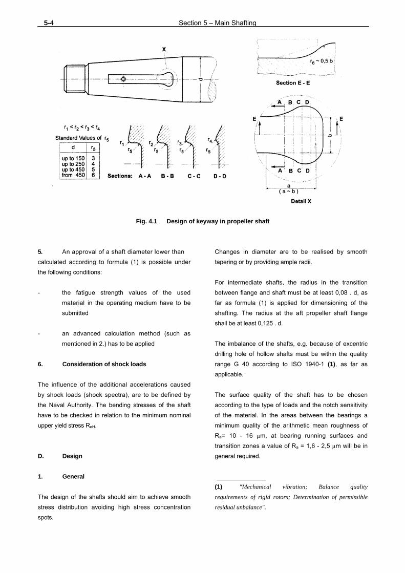
5-4 Section 5 – Main Shafting
Fig. 4.1 Design of keyway in propeller shaft
5. An approval of a shaft diameter lower than
calculated according to formula (1) is possible under
the following conditions:
- the fatigue strength values of the used
material in the operating medium have to be
submitted
- an advanced calculation method (such as
mentioned in 2.) has to be applied
6. Consideration of shock loads
The influence of the additional accelerations caused
by shock loads (shock spectra), are to be defined by
the Naval Authority. The bending stresses of the shaft
have to be checked in relation to the minimum nominal
upper yield stress ReH.
D. Design
1. General
The design of the shafts should aim to achieve smooth
stress distribution avoiding high stress concentration
spots.
Changes in diameter are to be realised by smooth
tapering or by providing ample radii.
For intermediate shafts, the radius in the transition
between flange and shaft must be at least 0,08 . d, as
far as formula (1) is applied for dimensioning of the
shafting. The radius at the aft propeller shaft flange
shall be at least 0,125 . d.
The imbalance of the shafts, e.g. because of excentric
drilling hole of hollow shafts must be within the quality
range G 40 according to ISO 1940-1 (1), as far as
applicable.
The surface quality of the shaft has to be chosen
according to the type of loads and the notch sensitivity
of the material. In the areas between the bearings a
minimum quality of the arithmetic mean roughness of
Ra= 10 - 16 µm, at bearing running surfaces and
transition zones a value of Ra = 1,6 - 2,5 µm will be in
general required.
(1) "Mechanical vibration; Balance quality
requirements of rigid rotors; Determination of permissible
residual unbalance".

Section 5 – Main Shafting 5-5
2. Shaft tapers and propeller nut threads
Shafts are in general connected by means of flanged or
sleeve couplings.
For flanged couplings a tapering of between 1 : 12 and
1 : 20 should be provided. For the taper of the propeller
connection Section 7 applies.
Fixed propellers shall be connected to the propeller
shaft by a pressure connection with pre-defined pull up
way.
The outside diameter of the threaded end of the pro-
peller securing nut should not be less than 60 % of the
calculated bigger taper diameter. The nut has to be
secured against the shaft, see Fig. 5.1.
3. Propeller shaft protection
3.1 Sealing
Propeller shafts with oil or grease lubrication are to be
provided at both ends with seals of proven
effectiveness, approved by TL, see also the
requirements applicable to the external sealing of the
stern tube in the context of the propeller shaft survey
described in Chapter 101 - Classification and Surveys,
Section 3.
For protection of the sealing a rope guard should be
provided.
The propeller boss seating is to be effectively
protected against the ingress of seawater. This seal at
the propeller can be dispensed with if the propeller shaft
is made of corrosion-resistant material.
3.2 Shaft liners
3.2.1 Propeller shafts which are not made of corro-
sion-resistant material and which run in seawater are
to be protected against contact with seawater by sea-
water-resistant metal liners or other liners approved by
TL and by seals of proven effectiveness on the propeller
side.
3.2.2 Metal liners in accordance with 3.2.1, which
run in seawater, must be made in a single piece. Only
with the expressed consent of TL and in exceptional
cases the liner may consist of two or more parts, pro-
vided that the abutting edges of the parts are addition-
ally sealed and protected, after fitting, by a method
approved by TL to guarantee water-tightness. Such
joints will be subject of special tests to prove their
effectiveness.
3.2.3 Minimum wall thickness
The minimum wall thickness s [mm] of metal shaft
liners in accordance with 3.2.1 is to be determined
using the following formula:
s = 0,03 d+ 7,5 (3)
d = shaft diameter under the liner [mm]
In the case of continuous liners, the wall thickness
between the bearings may be reduced to 0,75 s.
4. Couplings
4.1 Definitions
In the formulae (4), (5), (6) and (7), the following
symbols are used:
A = Effective area of shrink-fit seating, [mm2]
cA = Coefficient for shrink-fitted joints, depending on
the kind of driving unit [-]
= 1,0 for geared oil engine and turbine
drives,
= 1,2 for direct oil engine drives,
C = Conicity of shaft ends [-]
d = Shaft diameter in area of clamp-type coupling, [mm]
ds = Diameters of fitted bolts, [mm]
dk = Root diameter of necked-down bolts, [mm]
taperoflength
diametersin taper difference =
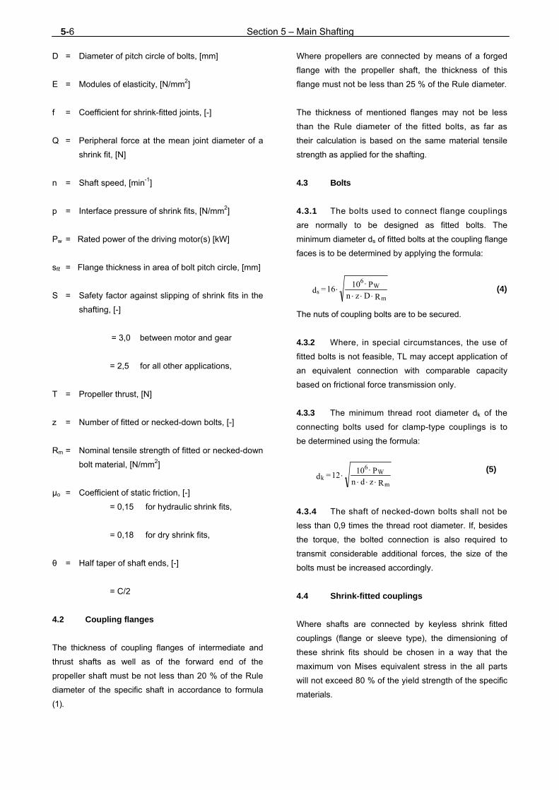
5-6 Section 5 – Main Shafting
D = Diameter of pitch circle of bolts, [mm]
E = Modules of elasticity, [N/mm2]
f = Coefficient for shrink-fitted joints, [-]
Q = Peripheral force at the mean joint diameter of a
shrink fit, [N]
n = Shaft speed, [min-1]
p = Interface pressure of shrink fits, [N/mm2]
Pw = Rated power of the driving motor(s) [kW]
sfℓ = Flange thickness in area of bolt pitch circle, [mm]
S = Safety factor against slipping of shrink fits in the
shafting, [-]
= 3,0 between motor and gear
= 2,5 for all other applications,
T = Propeller thrust, [N]
z = Number of fitted or necked-down bolts, [-]
Rm = Nominal tensile strength of fitted or necked-down
bolt material, [N/mm2]
μo = Coefficient of static friction, [-]
= 0,15 for hydraulic shrink fits,
= 0,18 for dry shrink fits,
θ = Half taper of shaft ends, [-]
= C/2
4.2 Coupling flanges
The thickness of coupling flanges of intermediate and
thrust shafts as well as of the forward end of the
propeller shaft must be not less than 20 % of the Rule
diameter of the specific shaft in accordance to formula
(1).
Where propellers are connected by means of a forged
flange with the propeller shaft, the thickness of this
flange must not be less than 25 % of the Rule diameter.
The thickness of mentioned flanges may not be less
than the Rule diameter of the fitted bolts, as far as
their calculation is based on the same material tensile
strength as applied for the shafting.
4.3 Bolts
4.3.1 The bolts used to connect flange couplings
are normally to be designed as fitted bolts. The
minimum diameter ds of fitted bolts at the coupling flange
faces is to be determined by applying the formula:
R D z n P 1016 = d
m
W6
s
(4)
The nuts of coupling bolts are to be secured.
4.3.2 Where, in special circumstances, the use of
fitted bolts is not feasible, TL may accept application of
an equivalent connection with comparable capacity
based on frictional force transmission only. 4.3.3 The minimum thread root diameter dk of the
connecting bolts used for clamp-type couplings is to
be determined using the formula:
(5)
4.3.4 The shaft of necked-down bolts shall not be
less than 0,9 times the thread root diameter. If, besides
the torque, the bolted connection is also required to
transmit considerable additional forces, the size of the
bolts must be increased accordingly.
4.4 Shrink-fitted couplings
Where shafts are connected by keyless shrink fitted
couplings (flange or sleeve type), the dimensioning of
these shrink fits should be chosen in a way that the
maximum von Mises equivalent stress in the all parts
will not exceed 80 % of the yield strength of the specific
materials.
R z d n P 10 12 = d
m
W6
k

Section 5 – Main Shafting 5-7
For the calculation of the safety margin of the connection
against slippage, the maximal (theoretical) clearance
will be applied, derived as the difference between the
lowest respectively highest still acceptable limit of the
applied nominal tolerance field for the bore and the
shaft. The contact pressure p [N/mm2] in the shrunk-on
joint to achieve the required safety margin may be
determined by applying formulae (6) and (7).
f A
T θ )T + Qc( f + T θ = p
22222
(6)
+ sign following the root applies to conical shrunk
joints without an axial stop to absorb astern
thrust.
- sign following the root if the conical shrunk
joint has an axial stop to absorb astern thrust.
Θ - S
μ = f 2
2o
(7)
5. Shafting bearings
5.1 Arrangement of shaft bearings
The location of shaft bearings both inside and outside
the stern tube should be determined, by means of
suitable alignment calculations, in a way that they are
subjected to positive reaction forces, irrespective of
the condition of the plant (hot/ cold) and the loading
condition of the ship.
By appropriate spacing of the bearings and by the
alignment of the shafting in relation to the flywheel of
the engine or output flange of the gear box, care is to
be taken to ensure that no undue shear forces or
bending moments are introduced to the crankshaft
respectively gear box when the plant is under
operational temperature (warm). The number and
spacing of the applied bearings should be chosen in a
way that the sensitivity of alignment remains low, i.e. no
critical loads occur even for the case of hull's
deflections or small deviations of nominal alignment due
to inaccuracies or wear.
In certain cases it will be recommended to check the
reaction forces of the bearing by appropriate alignment
calculations of the shafting.
Guide values for the maximum permissible distance
between bearings max [mm] can be determined using
formula (8):
(8)
d = Diameter of shaft between bearings, [mm]
K1 = 450 for oil-lubricated white metal
bearings,
= 280 for grey cast iron, grease-
lubricated stern tube bearings,
= 280–350 for water-lubricated rubber
bearings in stern tubes and shaft
brackets (upper values for
special designs only).
Where the shaft speed exceeds 350 min-1 it is
recommended that the maximum bearing spacing in
accordance with formula (9) be observed in order to
avoid excessive loads due to bending vibrations. If the
above guide formulae are not fulfilled special
considerations based on bending vibration analysis will
be applied.
(9)
n = Shaft speed, [min-1]
K2 = 8400 for oil-lubricated white metal
bearings,
= 5200 for grease-lubricated, grey cast
iron bearings and for rubber
bearings inside stern tubes and
tail shaft brackets.
In specific cases a bending (vibration) stress analysis
should be carried out for the shafting system.
5.2 Stern tube bearings
5.2.1 In general two stern tube bearings should be
provided. In short stern tubes the forward bearing may
be dispensed with. In such cases generally a further
free-standing intermediate shaft bearing will be
required.
d K = 1max
n
d K = 2max

5-8 Section 5 – Main Shafting
5.2.2 Where the propeller shaft inside the stern
tube runs in oil-lubricated white metal bearings or in
synthetic rubber or reinforced resin or plastic materials
approved for use in oil-lubricated stern tube bearings,
the lengths of the after and forward stern tube bearings
should be approximately 2 · da and 0,8 · da
respectively.
The length of the after stern tube bearing may be
reduced to 1,5 · da provided that the contact load, which
is calculated from the static load and considering the
weight of the propeller, is less than 0,8 Mpa for white
metal bearings and less than 0,6 Mpa for bearings
made of synthetic materials.
For approved materials higher surface pressure values
may be applied.
5.2.3 Where the propeller shaft inside the stern
tube runs in bearings made of lignum vitae, rubber or
plastic approved for use in water-lubricated stern tube
bearings, the length of the after stern tube bearing
should be approximately 4 · da and that of the forward
stern tube bearing approximately 1,5 da.
A reduction of the bearing length may be accepted,
provided that a superior load capacity of the bearing is
proven by adequate shop tests.
5.2.4 Where the propeller shaft runs in grease-
lubricated, grey cast iron bushes the lengths of the
after and forward stern tube bearings should be
approximately 2,5 . da and 1,0 . da respectively.
The peripheral speed of propeller shafts shall not
exceed
- 2,5 to maximal 3 m/s for grease-lubricated
grey cast iron bearings
- 6 m/s for water-lubricated rubber bearings
- 3 to maximal 4 m/s for water lubricated lignum
vitae bearings
5.2.5 Where propeller shafts are to run in roller
bearings inside the stern tube, preferably cylindrical
roller bearings with cambered rollers or races and with
increased bearing clearance should be used. The cam-
ber should be capable to cope with an inclination of
the shaft relative to the bearing's centre line of at least
0,1 % for continuous operation without adverse
effects.
For application of roller bearings care must be taken
that the minimal load requirements as specified by the
manufacturer are fulfilled (axial adjustment
recommended).
5.3 Bearing lubrication
Roller bearings may be used for the propeller shaft as
self-aligning radial bearings only.
5.3.1 The choice of lubrication as well as of the
materials for the bearings and their compatibility to
each other must take into consideration an anticipated
long-life marine application. 5.3.2 Lubricating oil or grease must be introduced
into the stern tube in such a way as to ensure a reliable
supply of oil or grease to the forward and aft stern
tube bearing.
When grease lubrication is applied, a separate grease
feeding connection must be provided for each forward
and after stern tube bearing.
For oil lubricated stern tube bearings, a header tank is
to be fitted at a sufficient height above the ship's load
line. Facilities are to be provided for checking the
level of oil in the tank at any time.
The temperature of the after stern tube bearing is to be
measured and indicated. Alternatively, with propeller
shafts less than 400 mm in diameter the stern tube oil
temperature may be measured and indicated. In such
cases the temperature sensor is to be located in the
vicinity of the after stern tube bearing.
In the case of ships with automated machinery,
Chapter 106 - Automation has to be complied with.
5.4 Stern tube connections
Oil-lubricated stern tubes are to be fitted with filling,
testing and drainage connections as well as with a vent
pipe.

Section 5 – Main Shafting 5-9
Where the propeller shaft runs in seawater, a flushing
line is to be fitted in front of the forward stern tube
bearing in place of the filling connection.
5.5 Cast resin mounting
The mounting of stern tubes and stern tube bearings
made of cast resin and also the seating of intermediate
shaft bearings on cast resin parts is to be carried out by
TL approved companies in the presence of a TL Sur-
veyor.
Only TL-approved cast resins may be used for stern
tube seatings.
The installation instructions issued by the manufacturer
of the cast resin must be observed.
E. Pressure Tests
1. Shaft liners
Prior to fitting, but as far as possible in the finish-
machined condition, shaft liners are to be subjected to a
hydraulic tightness test at 2 bar pressure.
2. Stern tubes
Prior to fitting but as far as possible in their finish-
worked condition, cast stern tubes are to be subjected
to a hydraulic tightness test at 2 bar pressure. A further
tightness test is to be carried out after fitting.
For stern tubes fabricated of welded steel plates, it is
sufficient to test for tightness during the pressure tests
applied to the hull spaces passed by the stern tube.
F. Special Requirements for Fibre Laminate Shafts
1. Theoretical strength calculation
The strength calculation must at least cover the
following failure modi in conjunction with the given
corresponding load cases:
(2) VOI calculation scheme under preparation.
- statical failure
Dimensioning to be performed against nominal
torque with a safety of 3.
- failure due to fatigue (high cycle)
As far as the shaft is not exposed to bending
stresses fatigue analysis may be carried out
for nominal torque plus 30 % torsional
vibration torque.
- buckling failure mode
Dimensioning may be estimated for a load of 3
times the nominal torque and in accordance
to the formulas in 2.
For the strength analysis the nominal strength of the
material has to be reduced by the factor 0,7 in order to
compensate random influence factors such as
geometrical and production inaccuracies as well as
environmental factors (moisture, temperature).
The calculation of the stress may be performed on the
basis of accepted analytical methods such as CLT
(Classical Laminate Theory) or FEM models. With
these stresses as input a set of failure modi in relation
to fibre and interfibre failure must be checked. This
set of failure modi must be coherent, i.e. a complete
and accepted theory . (2) 2. Buckling failure
For shafts made of anisotropic materials, such as
winded shafts of fibre laminate, buckling strength can be
checked for the critical torque by the following formula:
Cs = Factor depending on boundary conditions of
support
= 0,800 for free ends
= 0,925 ends simply supported
Nmνν1
E
0,5
Etr
6000
πCM
5/8
yzxy
y3/8x
9/45/4m
3
stcrit

5-10 Section 5 – Main Shafting
Ex = Modulus of elasticity in x-direction [N/mm2]
Ey = Modulus of elasticity in transverse
direction [N/mm2]
= unsupported length of shaft [mm]
rm, t = See C.4.
ν xy = Poisson's ratio of the laminate in
longitudinal direction
νyx = Poisson's ratio of the laminate in
peripheral direction
The design criteria is:
3,5 . Mt ≤ Mtcrit
Mt = Nominal torque at maximum continuous
rating [Nm]
3. Experimental strength investigation
Experimental strength investigation has to be provided
on request. Specifically:
- Testing of samples, if necessary for
verification of material data
- Prototype testing/process checking for
verification of the theoretical analysis in
presence of a TL Surveyor
- After a year or 3000 operating hours,
whichever is reached earlier, a visual
examination and optionally a crack or
delamination check of the fibre laminate
components is to be carried out by a TL
Surveyor.
4. Final documentation
After finalising manufacturing of the components an
updated documentation in the form of a list of all
definitive valid analyses and documents is to be sub-
mitted to TL. The documentation must refer to the
status quo and take into account all alterations or
optimisations introduced during designing and
manufacturing process as well as the achieved and
measured properties.
5. If fire protection requirements are relevant
for the composite shafting, specifically in the cases of
penetration of fire protection bulkheads and/or
redundant propulsion, appropriate provisions shall be
taken to ensure the required properties in consent with
TL.

Section 6 – Gear Couplings 6-1
SECTION 6
GEARS, COUPLINGS
A. General
1. Scope
1.1 These Rules apply to spur, planetary and
bevel gears and to all types of couplings for
incorporation in the main propulsion plant or essential
auxiliary machinery as specified in Section 1, B.4.
1.2 Documents for approval
Assembly and sectional drawings together with the
necessary detail drawings and parts lists are to be
submitted to TL in triplicate for approval. They must
contain all the data necessary to enable the load
calculations to be checked.
B. Materials
1. Approved materials
1.1 Shafts, pinions, wheels and wheel rims of
gears in the main propulsion plant should preferably
be made of forged steel. Rolled steel bar may also be
used for plain, flangeless shafts. Gear wheel bodies
may be made of grey cast iron (1) or nodular cast iron or
may be fabricated from welded steel plate with steel or
cast steel hubs.
1.2 Couplings in the main propulsion plant must
be made of steel, cast steel or nodular cast iron with a
mostly ferritic matrix. Grey cast iron or suitable cast
aluminium alloys may also be permitted for lightly
stressed external components of couplings and the
rotors and casings of hydraulic slip couplings.
(1) The peripheral speed of cast iron gear wheels
shall generally not exceed 60 m/s, that of cast iron coupling
clamps or bowls, 40 m/s.
1.3 The gears of essential auxiliary machinery
according to Section 1, B.4. are subject to the same
requirements as those specified in 1.1 as regards the
materials used. For gears intended for auxiliary
machinery other than that mentioned in Section 1,
B.4. other materials may also be permitted.
1.4 Flexible coupling bodies for essential
auxiliary machinery according to Section 1, B.4. may
generally be made of grey cast iron, and for the
outer coupling bodies a suitable aluminium alloy may
also be used. However, for generator sets use should
only be made of coupling bodies preferably made of
nodular cast iron with a mostly ferritic matrix, of steel or
of cast steel, to ensure that the couplings are well able
to withstand the shock torques occasioned by short
circuits. TL reserve the right to impose similar
requirements on the couplings of particular auxiliary
drive units.
2. Testing of materials
All gear and coupling components which are involved in
the transmission of torque and which are intended for
the main propulsion plant must be tested in accordance
with the TL Material Rules. The same applies to the
materials used for gear components with major torque
transmission function and couplings in generator drives.
Suitable documentation is to be submitted for the
materials used for the major components of the
couplings and gears of all other functionally essential
auxiliary machines in accordance with Section 1, B.4.
This documentation may take the form of a TL Material
Test Certificate or an acceptance test certificate issued
by the steelmaker.

6-2 Section 6 – Gear Couplings
C. Calculation of the Load-Bearing Capacity of
Gear Theeth
1. General
1.1 Components of the gearing system are:
- Gear
- Equipment for the gear lubrication and control
oil
- Cooling water equipment and switching
equipment
1.2 Gears have to be designed to meet the sound
level defined in the building specification. The following
design principles for low-noise gears are to be
considered:
- Elastic mounting of the gear directly on the
ship structure
- Fixed mounting of gear and drive unit on an
intermediate framing which is elastically
mounted on the ship structure
- Flexible couplings to the drive unit and to the
propeller shaft
- Use of low-noise types of toothing, such as
double helical gearing
- Installation of low-noise components, e.g.
rotary screw pumps, etc. for the gear
lubrication. Installation of pumps with small
suction height to avoid cavitation noise
2. Calculation of load capacity for spur and
bevel gears
2.1 General
2.1.1 The sufficient load capacity of the gear-tooth
system of main and auxiliary gears in ship propulsion
systems is to be demonstrated by load capacity calcu-
lations according to the international standards ISO
6336, ISO 9083 or DIN 3990 for spur gear tooth
systems respectively ISO 10300 or DIN 3991 for bevel
gears while maintaining the safety margins stated in
Table 6.1 for flank and root load.
Table 6.1 Minimum safety margins for contact
and root bending stress
CaseBoundary
conditions SH SF
1. Modulus mn
≤16 1,3 1,8
2. Modulus mn
>16
0,024 mn +
0,916 0,02 mn+1,48
3.
In the case of
two mutually
independent
main propulsion
systems up to an
input torque of
8 000 Nm
1,2 1,55
2.1.2 For gears in the main propulsion plant
proof of the sufficient mechanical strength of the roots
and flanks of gear teeth in accordance with the
formulae contained in this Section is linked to the
requirement that the accuracy of the teeth should
ensure sufficiently smooth gear operation combined with
satisfactory exploitation of the dynamic loading
capacity of the teeth. For this purpose, the magnitude of
the individual pitch error fp and of the total profile error
Ff should generally conform to at least quality 5 as
defined in DIN 3962 or 4 to ISO 1328, and in the case of
higher peripheral speeds generally to at least quality 4
as defined in DIN 3962 or 3 to ISO 1328. The total
error of the tooth trace fHß should conform at least to
quality 5 to DIN 3962, while the parallelism of axis
should at least meet the requirements of quality 5 or 4
to DIN 3964 or ISO 1328 respectively. The surface
roughness Rz of the tooth flanks of gears should gen-
erally not exceed 4 µm.
The tooth root radius ρao on the tool reference profile
should be at least 0,25 · mn.
TL reserve the right to call for proof of the accuracy of
the gear-cutting machines used and for testing of the
method used to harden the gear teeth.

Section 6 – Gear Couplings 6-3
3. Symbols, terms and summary of input
data
3.1 Indices
1 = pinion
2 = wheel
n = normal plane
t = transverse plane
o = tool
3.2 Parameters
a = Centre distance, [mm]
b = Face width, [mm]
beh = Effective face width (bevel gears), [mm]
BzO = Measure for shift of datum line
d = Standard pitch diameter [mm]
da = Tip diameter, [mm]
df = Root diameter, [mm]
Ft = Circular force at reference circle, [N]
Fβx = Initial equivalent misalignment, [m]
fpe = Normal pitch error, [m]
ff = Profile form error, [m]
ha0* = Addendum coefficient of tool, [-]
hf0* = Dedendum coefficient of tool, [-]
hFfP0*= Utilized dedendum coefficient of tool, [-]
KA = Application factor, [-]
KFα = Transverse load distribution factor (root
stress), [-]
KFβ = Face load distribution factor (root stress), [-]
KHα = Transverse load distribution factor (contact
stress), [-]
KHβ = Face load distribution factor (contact stress),
[-]
KHβ-be = Bearing factor (bevel gears), [-]
Kv = Dynamic factor, [-]
K = Load distribution factor. [-]
mn = Normal modul, [mm]
mnm = Mean normal modul (bevel gear), [mm]
n = Number of revolutions, [min-1]
NL = Number of load cycles, [min-1]
P = Transmitted power, [kW]
pr = Protuberance at tool, [mm]
Q = Toothing quality, acc. to DIN, [-]
q = Machining allowance, [mm]
Ra = Arithmetic mean roughness, [m]
RzF = Mean peak to valley roughness of root [m]
RzH = Mean peak to valley roughness of flank, [m]
SF = Safety factor against tooth breakage, [-]
SFG = Tooth root stress limit, [N/mm2]
SH = Safety factor against pittings, [-]
T = Torque, [Nm]
u = Gear ratio, [-]
x = Addendum modification coefficient, [-]
xhm = Mean addendum modification coefficient, [-]
xsm = Thickness modification coefficient, [-]
YF = Tooth from factor (root), [-]
YNT = Live factor (root), [-]
6-4 Section 6 – Gear Couplings
Yδ rel T = Relative notch sensitivity factor, [-]
YR rel T = Relative surface condition factor, [-]
YS = Stress correction factor, [-]
YST = Stress correction factor for reference test
gears, [-]
YX = Size factor for tooth root stress, [-]
Yβ = Helix angle factor for tooth root stress, [-]
z = Number of teeth, [-]
ZE = Elasticity factor, [-]
ZH = Zone factor (contact stress), [-]
ZL = Lubricant factor, [-]
ZNT = Live factor (contact stress), [-]
Zv = Speed factor, [-]
ZR = Roughness factor, [-]
ZW = Work-hardening factor, [-]
ZX = Size factor (contact stress), [-]
Zβ = Helix angle factor (contact stress), [-]
Zε = Contact ratio factor (contact stress), [-]
αn = Normal pressure angle, [°]
αpr = Protuberance angle, [°]
β = Helix angle, [°]
βm = Mean helix angle (bevel gears), [-]
υoil = Oil temperature, [°C]
40 = Kinematic viscosity of the oil at 40°C
[mm2/s]
ν100 = kinematic viscosity of the oil at 100°C
[mm2/s]
ρa0* = coefficient of tip radius of tool, [-]
Σ = Shaft angle (bevel gears), [°]
σF = Root bending stress, [N/mm2]
σFE = Root stress, [N/mm2]
σFG = Root stress limit, [N/mm2]
σF0 = Nominal root stress, [N/mm2]
σFlim = Endurance limit for bending stress, [N/mm2]
σFP = Permissible root stress, [N/mm2]
σH = Calculated contact stress, [N/mm2]
σHG = Modified contact stress limit, [N/mm2]
σHlim = Endurance limit for contact stress, [N/mm2]
σHP = Permissible contact stress, [N/mm2]
σH0 = Nominal contact stress, [N/mm2]
3.3 The input data required to carry out load-
bearing capacity calculations are summarized in Table
6.2.
4. Influence factors for load calculations
4.1 Rated torque
The calculation of the rated torque has to be based on
the planned maximum continuous rating.
4.2 Application factor KA
The application factor KA takes into account the
increase in rated torque caused by external increases
in dynamic and transient load. KA is determined for main
and auxiliary systems in accordance with Table 6.3.

Section 6 – Gear Couplings 6-5
Table 6.2 List of input data for evaluating load-bearing capacity
Yard./Newb. No. Reg. No.
Manufacturer
Type
Application
Cylindrical gear
Bevel gear (1)
Nominal rated power
P kW Ice class -
No. of revolutions
n1 1/min No. of planets -
Application factor
KA - Dynamic factor Kv
-
Face load distribution factors
KHβ Load distribution factor
K
KHβ-be(1) -
Transversal load distribution factors
KH
KFβ - KF
Geometry Data Pinion Wheel Tool Data Pinion Wheel
Number of teeth
z
-
-
Addendum modification coefficient
x
-
Normal modul
mn
mm Mean addendum modification coeff.
xhm(1)
-
Mean normal modul mnm(1)
mm
Thickness modification coeff.
xsm(1)
-
Normal pres. angle
αn
° Coefficient of tool tip
radius
ρa0*
-
Centre distance
a
mm Addendum coefficient of tool
ha0
*
-
Shaft angle
Σ(1)
° Dedendum
coefficient of tool
hf0*
-
Relative effective face width
beh/b(1)
-
Utiliz. ded. coeff. of tool hFfPO
*
Helix angle β ° Protuberance pr mm
Mean helix angle βm(1) ° Protuberance angle pr ° Face width
b
mm Machining allowance q
mm
Tip diameter
da
mm Measure at tool BzO
mm
Root diameter dfe mm Backlass allowance/tolerance -
Lubrication Data Quality
Kin.viskosity 40°C 40 mm2/s Quality acc. to DIN Q -
Kin.viskosity 100°C 100 mm2/sMean peak to valley roughness of flank RzH μm
Oil temperature Oil °C Mean peak to valley roughness of coot RzF μm
FZG class - Initial equivalent misalignment Fβx μm
Material Data Normal pitch error fpe
μm
Material type Profile form error ff μm
Endurance limit for contact stress σHlim N/mm2
Date : Signature :
Endurance limit for bending stress σFlim N/mm2
Surface hardness HV
Core hardness HV
Heat treatment method -
(1) Declaration for bevel gear.
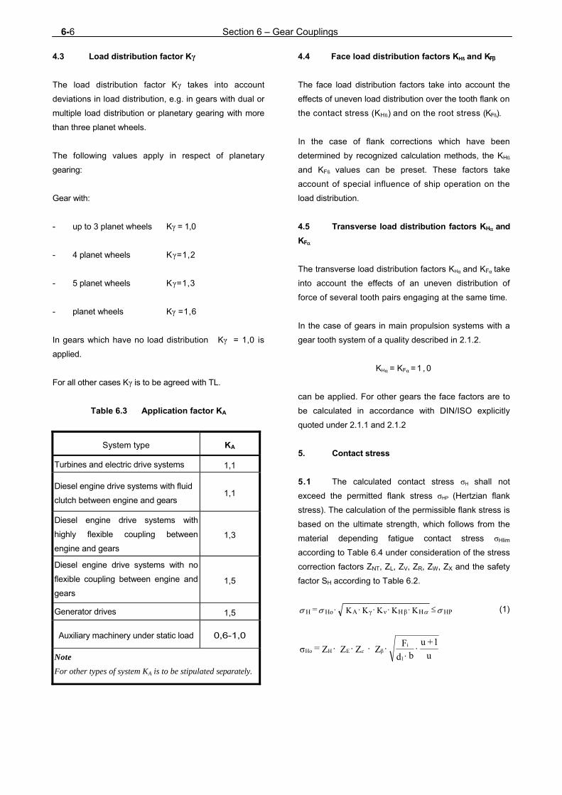
6-6 Section 6 – Gear Couplings
u
1+u
b d
F Z Z Z Z = σ1
iβEHHo
4.3 Load distribution factor Kγ
The load distribution factor Kγ takes into account
deviations in load distribution, e.g. in gears with dual or
multiple load distribution or planetary gearing with more
than three planet wheels.
The following values apply in respect of planetary
gearing:
Gear with:
- up to 3 planet wheels Kγ = 1,0
- 4 planet wheels Kγ=1,2
- 5 planet wheels Kγ=1,3
- planet wheels Kγ =1,6
In gears which have no load distribution Kγ = 1,0 is
applied.
For all other cases Kγ is to be agreed with TL.
Table 6.3 Application factor KA
System type KA
Turbines and electric drive systems 1,1
Diesel engine drive systems with fluid
clutch between engine and gears 1,1
Diesel engine drive systems with
highly flexible coupling between
engine and gears
1,3
Diesel engine drive systems with no
flexible coupling between engine and
gears
1,5
Generator drives 1,5
Auxiliary machinery under static load 0,6-1,0
Note
For other types of system KA is to be stipulated separately.
4.4 Face load distribution factors KHß and KFβ
The face load distribution factors take into account the
effects of uneven load distribution over the tooth flank on
the contact stress (KHß) and on the root stress (KFß).
In the case of flank corrections which have been
determined by recognized calculation methods, the KHß
and KFß values can be preset. These factors take
account of special influence of ship operation on the
load distribution.
4.5 Transverse load distribution factors KH and
KF
The transverse load distribution factors KHα and KFα take
into account the effects of an uneven distribution of
force of several tooth pairs engaging at the same time.
In the case of gears in main propulsion systems with a
gear tooth system of a quality described in 2.1.2.
KHα = KFα = 1 , 0
can be applied. For other gears the face factors are to
be calculated in accordance with DIN/ISO explicitly
quoted under 2.1.1 and 2.1.2
5. Contact stress
5.1 The calculated contact stress σH shall not
exceed the permitted flank stress σHP (Hertzian flank
stress). The calculation of the permissible flank stress is
based on the ultimate strength, which follows from the
material depending fatigue contact stress σHlim
according to Table 6.4 under consideration of the stress
correction factors ZNT, ZL, ZV, ZR, ZW, ZX and the safety
factor SH according to Table 6.2.
HPHβHνγAHoH K K K K K = (1)

Section 6 – Gear Couplings 6-7
5.2 The permissible contact stress σHP shall include
a safety margin SH as given in Table 6.1 against the
contact stress limit σHG which is determined from the
material-dependent fatigue strength σHlim as shown in
Table 6.4 (2) allowing for the stress correction factors
ZNT, ZL, ZV, ZR, ZW, ZX.
H
HGHP S
σ = σ (2)
σHG = σHlim · ZNT · ZL · ZV · ZR · ZW · ZX
Table 6.4 Endurance limits (3) for contact stress
σHlim
Material σH lim [N/mm2]
Case-hardening steels, case-
hardened 1500
Nitriding steels, gas nitrided 1250
Alloyed heat treatable steels,
bath or gas nitrided 850-1000
Alloyed heat treatable steels,
induction hardened 0,7HV10 + 800
Alloyed heat treatable steel 1,3HV10 + 350
Unalloyed heat treatable steel 0,9HV10 + 370
Structural steel 1,0 HB + 200
Cast steel, cast iron and
nodular cast graphite 1,0 HB + 150
(2) With consent of TL for case hardened steel with
proven quality higher endurance limits may be accepted.
(3) With consent of TL for case hardened steel with
or over proven quality application of higher values for fatigue
strength may be accepted.
Table 6.5 Endurance limit for tooth root bending
stress σFE = σFlim · YST, with YST =2
Material σFE=σFlim
* ·YST
[N/mm2]
Case-hardened steels, case-
hardened 860 - 920
Nitriding steels, gas nitrided 850
Alloyed heat treatable steel,
bath or gas nitrided 740
Alloyed heat treatable steel,
induction hardened 700
Alloyed heat treatable steels,
heat treated 0,8HV10 + 400
Unalloyed heat treatable steels 0,6 HV10 + 320
Structural steel 0,8HB+180
Cast steel, cast iron with
nodular graphite 0,8HB+140
Note
For alternating stressed toothing only 70 % of these
values are permissible.
6. Tooth root bending stress
6.1 The calculated maximum root bending
stress σF of the teeth shall not exceed the permissible
root stress σFP of the teeth. The calculation of the
permissible root bending stress is based on the
ultimate strength σFG, which follows from the material
depending fatigue root stress σF lim according to Table
6.5 under consideration of the stress correction
factors YST, YNT, Y δ rel T, YR rel T, YX and the safety factor SF
according to Table 6.1.
The tooth root stress is to be calculated separately for
pinion and wheel.
σF = σF0· KA· KV· K · KFβ· KFα ≤ σFP (3)
Y Y Y m b
F= σ βSF
n
tF0

6-8 Section 6 – Gear Couplings
6.2 The permissible root bending stress σFP
shall have a safety margin SF as indicated in Table
6.1 against the root stress limit σFG which is determined
from the material-dependent fatigue strength σFE or
σFlim accordance with Table 6.5 (2), allowing for the
stress correction factors YST, YNT, Y δ rel T, YR rel T, YX.
S
σ = σF
FGFP (4)
σFG = σF lim · YST · YNT · Yδ rel T · YR rel T · YX
D. Gear Shafts
1. Minimum diameter
The dimensions of shafts of reversing and reduction
gears are to be calculated by applying the following
formula:
(3)
0,4 d
dfor a
i the expression
1,0tosetbemayd
d - 14
a
i
d = Required outside diameter of shaft, [mm]
di = Diameter of shaft bore, if applicable, [mm]
da = Actual shaft diameter, [mm]
P = Driving power of shaft, [kW]
n = Shaft speed, [min-1]
F = Factor for the type of drive, [-]
= 95 for turbine plants, electrical drives and
engines with slip couplings,
= 100 for all other types of drive. TL reserve
the right to specify higher F values if
this appears necessary in view of the
loading of the plant.
CW = material factor
=
Rm = tensile strength of the shaft material
For whell shafts no higher than 800
N/mm2.shall be used. For pinion shafts the
actual tensile strength may be used.
k = 1,10 for gear shafts
= 1,15 in the area of the pinion or wheel
body is this is keyed to the shaft
and for multiple-spline shafts.
Higher values of k may be specified by TL
where increased bending stresses in the
shaft are expected because of the bearing
arrangement, the casing design, the tooth
pressure, etc.
E. Equipment
1. Gear lubrication
1.1 General
The gear system has to be designed to enable a start
with a lubrication oil temperature from 0°C upwards
without restrictions.
For engageable couplings the guidelines according to
G.5. are valid.
Suitable equipment has to be provided, which limits
the water content in the gear lubricant and the humidity
within the gear in a way to exclude corrosion in the gear.
1.2 Oil level indicator
For monitoring the lubricating oil level in main and
auxiliary gears, equipment must be fitted to enable the
oil level to be determined.
160R
500
m
3
W
a
i
4 C
dd - 1 n
P k F d

Section 6 – Gear Couplings 6-9
1.3 Pressure and temperature control
Temperature and pressure gauges are to be fitted to
monitor the lubricating oil pressure and the lubricating oil
temperature at the oil-cooler outlet before it enters the
gears.
Plain journal bearings are also to be fitted with
temperature indicators.
Where gears are fitted with plane bearings, a
temperature indicator is to be mounted at a suitable
point. For gears rated up to 2 000 kW, special
arrangements may be agreed with TL.
Where ships are equipped with automated machinery,
the requirements of Chapter 106 - Automation are to be
complied with.
1.4 Lubricating oil pumps
Lubricating oil pumps driven by the gearing must be
mounted in such a way that they are accessible and
can be replaced easily by using common board
available tools.
The supply of lubricating oil has to be ensured by a
main pump and an independent stand by pump. If a
reduction gear is approved for sufficient self
lubrication at 75 % of the driving torque, the stand by
pump may be abolished up to a performance relation
P/n1 [kW/min-1]≤ 3,0.
2. Equipment for operation, control and safety
Equipment for operation and control has to enable a
safe operation of the gear by remote control as well as
directly at the gear. All parameters which are important
for a regular operation must be indicated directly at the
gear. These indicating instruments shall be put together
in an auxiliary control stand, as far as possible.
3. Gear casings
The casings of gears belonging to the main propulsion
plant and to important auxiliaries must be fitted with
removable inspection covers to enable the gears to be
inspected, the thrust bearing clearance to be measured
and the oil sump to be cleaned.
4. Seating of gears
It has to be taken care that no inadmissible forces
caused by deformation of the foundation as part of the
hull structure are transfered to the toothing.
The seating of gears on steel or cast resin chocks is to
conform to the TL Rules , Guidelines for the Seating of
Propulsion Plants.
For the seating of gears on casting resin chocks the
thrust must be absorbed by stoppers. The same applies
for casting resin foundations of separate thrust
bearings.
F. Balancing and Testing
1. Balancing quality
1.1 Gear wheels, pinions, shafts, gear
couplings and, where applicable, high-speed flexible
couplings must be assembled in a properly balanced
condition.
1.2 The following balancing quality ranges
according to DIN/ISO 1940, Part 1 have to be met:
- 6,3 for gear shafts, pinion and coupling
members for engine gears
- 2,5 for torsion shafts and gear couplings,
pinions and gear wheels belonging to
turbine transmissions
2. Testing
2.1 Testing in the manufacturer's works
When the testing of materials and component tests
have been carried out, gearing systems for the main
propulsion plant are to be presented to TL for final
inspection and operational testing in the
manufacturer's works. The final inspection is to be
combined with a trial run lasting several hours under
part or full-load conditions, on which occasion the tooth
clearance and contact pattern are to be checked. In the
case of a trial at full-load, any necessary running-in of
the gears must have been completed beforehand.

6-10 Section 6 – Gear Couplings
Where no test facilities are available for the operational
and on-load testing of large gear trains, these tests may
also be performed on board ship on the occasion of the
dock trials.
Tightness tests are to be performed on those
components to which such testing is appropriate.
Reductions in the scope of the tests require the consent
of TL.
2.2 Tests during sea trials
2.2.1 Prior to the start of sea trials, the teeth of the
gears belonging to the main propulsion plant are to be
coloured with suitable dye to enable the contact
pattern to be established. During the sea trials, the
gears are to be checked at all forward and reverse
speeds to establish their operational efficiency and
smooth running as well as the bearing temperatures
and the freedom from contamination of the lubricating
oil. At the latest on conclusion of the sea trials, the
gearing is to be examined via the inspection openings
and the contact pattern checked. If possible the contact
pattern has to be checked after conclusion of every
load step. Assessment of the contact pattern is to be
based on the guide values for the proportional area of
contact in the axial and radial directions of the teeth
given in Table 6.6 and shall take account of the
running time and loading of the gears during the sea
trial.
2.2.2 In the case of multistage gear trains and
planetary gears manufactured to a proven high degree
of accuracy and if the check has been satisfying after a
load test of several hours in the workshop of the
manufacturer or if the bearing face of all tooth
meshings has been proven at a type test under full
load, checking of the contact pattern may, with the
consent of TL, be reduced in scope.
2.3 Acoustic properties to be proven in
compliance with Chapter 102 - Hull Structures and Ship
Equipment, Section 16, B.3.
Table 5.6 Percentage area of contact
Material, shaping of teeth
Working depth (without tip
relief)
Width of tooth (without end
relief)
heat-treated, hobbed, formed by generating method
33% average values
70%
surface-hardened, ground, shaved
40% average values
80%
G. Design and Construction of Couplings
1. It must be possible to disengage respectively
to install and dismantle all couplings outside of gears
using the tooling on board without displacing of major
system's components such as gear, thrust bearing,
engine etc.
2. Flange and clamp-type couplings
In the dimensional design of the coupling bodies,
flanges and bolts of flange and clamp-type couplings,
the Rules specified in Section 5 are to be complied
with.
3. Tooth couplings
3.1 Torsionally stiff couplings, such as multi-
tooth couplings may be used to compensate deviations
in radial and axial direction.
3.2 Adequate loading capacity of the tooth flanks
of straight-flanked tooth couplings requires that the
following conditions are satisfied:
p n z d h bK P 10 9,9
= p permA
8
(4)
4,5 d n
10 P2m
3
15
G
(5)
Values close to 4,5 are allowed only with high
manufacturing accuracy and little residual imbalance.
Section 6 – Gears, Couplings 6-11
Where methods of calculation recognized by TL are
used for determining the Hertzian stress on the flanks of
tooth couplings with convex tooth flanks, the
permissible Hertzian stresses are equal to 75 % of the
values of σHP with stress correction factors set to 1.0:
P = Driving power at coupling, [kW]
d = Standard pitch diameter, [mm]
KA = Application factor in accordance with C.4.2,
[-]
z = Number of teeth, [-]
n = Speed in rev/min, [min-1]
h = Working depth of toothing, [mm]
b = Load-bearing tooth width, [mm]
dm = Diameter of gyration, [mm]
G = Mass of coupling sleeve, [kg]
σHP = Permissible Hertzian stress, [N/mm2]
p = Loading capacity of the tooth flanks, [N/mm2]
pperm =400 - 600 N/mm2
for tooth systems of quenched and
tempered steel; the higher values apply
to higher-strength steels, higher quality
toothing and superior surface finishes.
=800 - 1000 N/mm2
for hardened and possibly ground tooth
systems; the higher values apply
primarily to nitrided tooth systems of
superior surface finish manufactured to
close tolerances.
3.3 The coupling teeth are to be effectively
lubricated. For this purpose a permanent oil or grease
lubrication in the coupling may generally be regarded as
adequate where
9
1062
nd [mm/min2] (6)
For higher values of d · n2, couplings in main propulsion
plants are to be provided with a circulating lubrication oil
system.
3.4 For the dimensional design of the sleeves,
flanges and bolts of gear couplings the formulae given
in Section 5 are to be applied.
4. Flexible couplings
4.1 Flexible couplings must be approved for the
loads specified by the manufacturer and for use in main
propulsion plants and essential auxiliary machinery.
It must be ensured that no damage occurs from oil or
fuel on flexible components.
The radial and axial deviations as well as the angle
deviations which have to be compensated by the flexi-
ble coupling are to be defined in the building specifi-
cation, both in the way of peak and steady (operational)
values.
4.2 Flexible couplings in the main drive have to
be so dimensioned that they withstand an operation
with intermittent ignition at an arbitrary cylinder during a
reasonable time. Additional dynamic loads due
to torsional vibration must be considered in this respect.
Reference is made to Section 8.
4.3 With regard to the casings, flanges and bolts
of flexible couplings, the requirements specified in
Section 5, D. are to be complied with.
4.4 The couplings must be able to compensate all
relative displacements occuring during operation
without initiating further inadmissible forces for the
adjacent elements of the plant. If a flexible coupling is
causing - according to its type - during operation
thrust to the coupled elements, care must be taken to
absorb these forces by bearings.
5. Clutches
Clutches have to be designed under consideration of
the defined operation characteristics. It has to be en
sured that in the open condition the driven secondary
parts of the clutch are exposed to residual, negligible

6-12 Section 6 – Gear Couplings
torque only. A limitation of speed and time for the
operation of the disengaged clutch within the opera-
tional speed range is inadmissible. It must be ensured,
that:
- the heat created during clutch in/out procedure
is controlled sufficiently i.e. does not lead to
overheating
- in case of a drop of the control clutch pressure
the stand by pump will be activated
automatically
- for air controlled clutches a redundancy is
established in case of a compressed air failure
- for electrically activated clutches an automatic
switching to a second feeding is provided
- the actual position (in/out) is indicated (for this
see also Section 2)
6. Hydraulic couplings/Torque converters
The torque characteristic of the hydraulic coupling has
to be adjusted to the operating conditions. As hydraulic
oil the lubricating oil required for the diesel engines or
the gears shall be used.
A timely unlimited operation of the drive machines with
empty coupling must be guaranteed for the whole speed
range. The actual operation condition has to be
indicated (for this see also Section 2).
7. Mechanical clutches for multi-engine
synchronization
7.1 Basic description
For propulsion plants driven by multiple power sources
of different type (such as diesel engines and turbines)
generally a switching over to alternative operational
modes without intermediate shut-down or reduction of
the speed of the driving engine may be required. For
such purposes a synchronisation of the speed of the
engines in duty and the idling engine should take place
before introduction of mechanical clutch in procedure.
The synchronisation aims to minimise the clutch in
shock and induced peak torques, but also to enable an
undisturbed and smooth continuous operation while
changing the operational mode. The speed difference
before introduction of clutch in procedure should not be
more than 10%, or depending on the moment of inertias
of the driving and driven parts the transient speed drop
or increase after clutch in should be less than 5%.
7.2 Design requirements
The mechanical part of the clutch may be of multiple
disc or mechanical teeth type. All components must be
designed for the nominal transmitted torque with a
safety factor of 2,5. In case that the speed is not
synchronised in accordance to 7.1 a safety factor of 3,5
must be reckoned with. In case that multiple disc plates
or other frictional devices are applied, they should be
set in a way that the slip point is reached for torque
values between 150 % and 250 % of the nominal
torque, depending on the requirements of the
manufacturer.
Additional functions, like lock-in/lock-out control or
position indication may be required depending on the
overall design of the propulsion plant.
8. Testing
Couplings for ship propulsion plants and couplings for
generator sets and transverse thrusters are to be
presented to TL for final inspection and, where
appropriate, for the performance of functional and
tightness tests.

Section 7 – Propeller 7-1
SECTION 7
PROPELLER A. General 1. Scope
These Rules apply to screw propellers as well as
miscellaneous propulsion systems. See Section 9 for
information on propeller sizes and materials for ships
navigating in ice.
2. Documents for approval 2.1 Design drawings of propellers in main pro-
pulsion systems having an engine output in excess of
300 kW and in transverse thrust systems of over 500
kW, are to be submitted to TL in triplicate for
examination. The drawings are required to contain all
the details necessary to carry out an examination in
accordance with the following requirements. 2.2 In the case of controllable pitch propeller
systems, general drawings and sectional drawings are
to be submitted in triplicate in addition to the design
drawings for blade, boss and pitch control mechanisms.
Control and hydraulic diagrams are to be attached to a
description of the functional characteristics. In the case
of new designs or controllable pitch propeller systems
which are being installed for the first time on a vessel
with TL Class, a description of the controllable pitch
propeller system has also to be provided.
3. Design
3.1 Propellers are to be designed in a way that
their power consumption lies within the family of
characteristics of the driving machinery.
- The propeller of controllable pitch plants shall
absorb the continuous rating of the driving
machinery at nominal speed.
- A fixed pitch propeller shall reach the absorbed
power/speed relation defined in the building
specification at nominal speed.
Note:
The maximum ahead pitch of CPP's should be 8 % greater
than the design pitch.
3.2 The construction of controllable pitch plants
has to be flood safe.
3.3 For determination of the propeller parameters
well known and established methods may be used. The
lay out of the propeller has to consider the noise
requirements in the building specification, e.g. minimum
circumferential speed, etc. Nominal speed ahead and
propeller diameter are to be selected for a maximum
ship speed without cavitation. The limit curve for
cavitation noise in the Sigma n - CTh diagram in L. may
be used. The noise emission from the propeller shall be
estimated already in the concept phase.
4. Designation
Each propeller and the essential components for torque
transmission and for blade adjustment of controllable
pitch propellers respectively have to be definitely
marked with the appropriate steel-stamp. The markings
have to be executed by steel-stamp numbers with
rounded edges to avoid notch effects.
B. Materials
1. Propellers and propeller hubs
The material for the propulsion device has to be
selected according to the actual functional
requirements. Special materials are not prescribed.
7-2 Section 7 – Propeller
Materials and their parameters may be taken from the
TL Material Rules.
Metallic propellers are to be made of sea-water-
resistant copper cast alloys or steel cast alloys with a
minimum tensile strength Rm of 440 N/mm2 and with
sufficient bending fatigue strength.
For the purpose of the following design Rules governing
the thickness of the propeller blades, the requisite
resistance to seawater of a cast copper alloy or cast
steel alloy is considered to be achieved if the alloy can
withstand a fatigue test under alternating bending
stresses comprising 108 load cycles amounting to about
20 % of the minimum tensile strength and carried out in
a 3 % NaCl solution, and if it can be proven that the
fatigue strength under alternating bending stresses in
natural seawater is not less than about 65 % of the
values established in 3 % NaCl solution. Sufficient
fatigue strength under alternating bending stresses
must be proven by a method recognized by TL.
2. Components for controllable pitch propellers and built-up propellers
The materials of the major components of the pitch
control mechanism and also the blade and boss
retaining bolts must comply with the requirement
pertaining to metallic materials.
The blade retaining bolts of assembled propellers or
controllable pitch propellers are to be manufactured of
seawater-resistant materials if they are not protected
against contact with seawater.
3. Material parameters
The material has to be documented according to the TL
Material Rules, Sections 12.
For the definition of the final material the manufacturer
has to deliver the following data:
- Designation of the material (acronym)
- Chemical composition
- Tensile strength, yield stress and elongation of
a material sample (serves especially for the
identification of the material)
- Bending fatigue strength in sea water spray fog
(serves as limit value for the strength calcula-
tions)
- Density of material, modulus of elasticity, ther-
mal expansion coefficient
- Magnetic characteristics, if applicable
- Information concerning repairing ability (weld-
ability, heat treatment)
- Information concerning resistance against
corrosion and erosion
4. Novel materials
Where it is proposed to use propeller materials which
serviceability is not attested by a sufficient period of
practical experience, TL must be provided with special
proof of the suitability of such materials.
5. Material testing
The material of propellers, propeller bosses and all
other major components involved in the transmission of
torque and pitch setting is to be tested in accordance
with the TL Material Rules. This also applies to
components which are used to control the blades and
also to propellers in main propulsion systems smaller
than 300 kW and transverse thrust systems of less than
500 kW.
C. Design and Dimensioning of Propellers
1. Noise behaviour 1.1 Cavitation noise
The propeller has to be designed to develop low noise,
especially at the nominal acoustic operation point.
Cavitation noise has to be avoided.
Note
Guiding values for cavitation avoidance are contained in L.

Section 7 – Propeller 7-3
1.2 Singing behaviour
By calculating the natural frequencies of the propeller
and by a comparison with the hydrodynamic excitation
at the trailing edges the risk of singing of the propeller
has to be estimated and minimized. If singing is
observed during trials, relevant counter measures have
to be applied.
Note:
The singing of a propeller is a strong peak tone in the noise
spectrum. It is created by the excitation of natural frequencies
as a consequence of vortex shedding at the trailing edge.
1.3 Air blow-out device
1.3.1 Blow-out devices for air may be considered for
naval ships for which low-noise operation is required in
velocity ranges with cavitating propeller. If an air blow-
out device is required in the building specification, the
system has to be agreed with the Naval Authority and
TL. The details of the design have to be included in the
building specification. 1.3.2 The exits of the blown-out air have to be
arranged in a way that a compact air veil covers the
blade surface. The feed of the air into the propulsion
system should be done at the front end of the propeller
shaft. The air temperature at the shaft entrance should
not be higher than 40°C. By special measures in the
construction it has to be secured that no air penetrates
into the hydraulic system. On the other hand no oil or
water shall get into the air system. 1.3.3 For the creation of an effective air veil at the
propeller blade the required air volume is depending on
the propeller speed. Therefore speed regulated air
compressors have to be provided. 1.3.4 All components and pipes of the air system
have to be made of stainless steel.
1.3.5 For ships with NBC protection the air should be
sucked from outside of the citadel. Ventilation and
drainage pipes shall be conducted in closed form to the
outside.
1.4 Measurements of water-borne noise
1.4.1 The measurements of water-borne noise have
to be executed in deep and shallow water according to
the building specification. 1.4.2 For the assessment of cavitation noise the
following test criteria will be applied simultaneously:
- Recording audible noise in the frequency range
30 Hz - 20 kHz
- Comparative evaluation of the relevant third
filter analyses. Checking if a clear increase of
noise level in the complete frequency range
above 1 kHz is to be observed or if with
increased speed a transfer of the noise peak to
the range of 100 Hz is happening
- Creation of a DEMON ("Demolition of Envelop
Modulation on Noise") spectrum
- Measurement of the target level with a linear
antenna
1.4.3 The execution of the measurements and the
documentation of results has to be coordinated with TL.
2. Symbols and terms
A = Effective area of a shrink fit, [mm2]
AD = Propeller plane area [m2]
B = Developed blade width of cylindrical
sections at radii 0,25R, 0,35R and 0,6R,
[mm]
cA = Coefficient for shrunk joints, [-]
= 1,0 for engine and turbine gear
transmissions,
= 1,2 for direct drives,
CG = Size factor in accordance with formula (2),
[-]
CDyn = Dynamic load factor in accordance with
formula (3), [-]

7-4 Section 7 – Propeller
Cw = Characteristic value for propeller material
as shown in Table 7.1 (corresponds to the
minimum tensile strength Rm of the
propeller material). [-]
C = Conicity of shaft ends, [-]
taperoflength
diameterin taper difference =
Table 7.1 Characteristic values Cw
Material Description (1) Cw
Cu 1 Cast manganese brass 440
Cu 2 Cast manganese nickel brass 440
Cu 3 Cast nickel aluminium bronze 590
Cu 4 Cast manganese aluminium
bronze
630
Fe 3 Martensitic cast chrome steel
13/1-6
660
Fe 4 Martensitic-austenitic cast steel
17/4
600
Fe 5 Ferritic-austenitic cast steel 600
Fe 6 Austenitic cast steel 17/8-11 500
(1) For the chemical composition of the alloys, see TL
Rules - Materials and Welding
CTh = Thrust load coefficient
=
D2A
Avρ0,5
T
d = Pitch circle diameter of blade or propeller-
fastening bolts, [mm] dk = Root diameter of blade or propeller-
fastening bolts, [mm] D = Diameter of propeller, [mm] = 2 · R dm = Mean taper diameter, [mm] e = Blade rake acc. Fig. 7.1 [mm] = R · tan
ET = Thrust stimulating factor in accordance with formula (5). [-]
f,f1,f2,f3 = Factors in formulae (2), (3), (4) and (7),
[-]
FM = Bolt load, [N]
H = Propeller blade face pitch at radii 0,25R,
0,35R and 0,6R [mm]
Hm = Mean effective propeller pitch on blade
for pitch varying with the radius, [mm]
B) (R
H) B (R =
R, B and H are to be substituted by values
corresponding to the pitch at the various
radii.
k = Coefficient for various profile shapes
for some examples, see Table 7.2, [-]
Table 7.2 Values of k for examples of various profile shapes
Profile shape
k
0,25R
0,35R
0,6R
Segmental profiles with circular arced back, x = 0,12
73 62 44
Segmental profiles with parabolic back, x = 0,11
77 66 47
Blade profiles as for Wageningen B series propellers
x0,25 = 0,10
x0,35 = 0,11
x0,60 = 0,12
80
66
44
LM = 2/3 of the leading-edge component of the
blade width at 0,9R, but at least 1/4 of the
total blade width at 0,9R for propellers with
heavily raked blades. [mm]
L = Pull-up length when mounting propeller on
taper, [mm]
Lmech = Pull-up length at t = 35°C [mm]
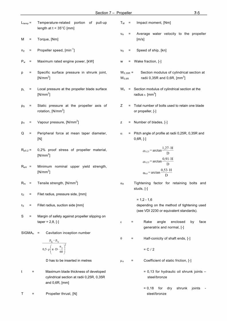
Section 7 – Propeller 7-5
Ltemp = Temperature-related portion of pull-up
length at t < 35°C [mm]
M = Torque, [Nm]
n2 = Propeller speed, [min-1]
Pw = Maximum rated engine power, [kW]
p = Specific surface pressure in shrunk joint,
[N/mm2]
pL = Local pressure at the propeller blade surface
[N/mm2]
pS = Static pressure at the propeller axis of
rotation, [N/mm2]
pV = Vapour pressure, [N/mm2]
Q = Peripheral force at mean taper diameter,
[N]
Rp0,2 = 0,2% proof stress of propeller material,
[N/mm2]
ReH = Minimum nominal upper yield strength,
[N/mm2]
Rm = Tensile strength, [N/mm2]
rD = Filet radius, pressure side, [mm]
rS = Fillet radius, suction side [mm]
S = Margin of safety against propeller slipping on
taper = 2,8, [-]
SIGMAn = Cavitation inception number
D has to be inserted in metres
t = Maximum blade thickness of developed
cylindrical section at radii 0,25R, 0,35R
and 0,6R, [mm]
T = Propeller thrust, [N]
TM = Impact moment, [Nm]
vA = Average water velocity to the propeller
[m/s]
vS = Speed of ship, [kn]
w = Wake fraction, [-]
W0,35R = Section modulus of cylindrical section at
W0,6R radii 0,35R and 0,6R, [mm3]
Wx = Section modulus of cylindrical section at the
radius x [mm3]
Z = Total number of bolts used to retain one blade
or propeller, [-]
z = Number of blades, [-]
= Pitch angle of profile at radii 0,25R, 0,35R and
0,6R, [-]
αA Tightening factor for retaining bolts and
studs, [-]
= 1,2 - 1,6
depending on the method of tightening used
(see VDI 2230 or equivalent standards).
= Rake angle enclosed by face
generatrix and normal, [-]
θ = Half-conicity of shaft ends, [-]
= C / 2
o = Coefficient of static friction, [-]
= 0,13 for hydraulic oil shrunk joints –
steel/bronze
= 0,18 for dry shrunk joints -
steel/bronze
2
2
VS
60
nDπρ0,5
pp
D
H 1,27arctan = 0,25
D
H 0,91arctan = 0,35
D
H 0,53arctan = α0,6
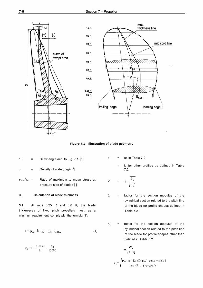
7-6 Section 7 – Propeller
Figure 7.1 Illustration of blade geometry
Ψ = Skew angle acc. to Fig. 7.1, [°]
= Density of water, [kg/m3]
σmax/σm = Ratio of maximum to mean stress at
pressure side of blades [-]
3. Calculation of blade thickness
3.1 At radii 0,25 R and 0,6 R, the blade
thicknesses of fixed pitch propellers must, as a
minimum requirement, comply with the formula (1):
C C K k K =t DynG1o (1)
15000
n +
H
cos e + 1 = Ko
2
k = as in Table 7.2 = k’ for other profiles as defined in Table
7.2.
k’ = 'β
βk
x
x
βx = factor for the section modulus of the
cylindrical section related to the pitch line
of the blade for profile shapes defined in
Table 7.2
βx’ = factor for the section modulus of the
cylindrical section related to the pitch line
of the blade for profile shapes other than
defined in Table 7.2
εcos C z B n
]sin + cos )H(D/ [2 10P = K 2W
m5
W1
2
Bt
W2
x

Section 7 – Propeller 7-7
CG = Size factor, [-]
0,85 12,2
D + f 1,1 1 (2)
D has to be inserted in [m],
f1 = 7,2 for monobloc propellers,
= 6,2 for separately casted blades of
variable-pitch or built-up propellers,
CDyn = Dynamic factor, [-]
1,0 f + 0,5
f1)-/( =
3
3mmax (3)
for 1,5 > m
max
otherwise
= 1,0
σmax/σm can be roughly calculated from the thrust-
stimulating factor ET according to formula (5). For a
more accurate calculation proceed according to 3.5.
1 + E f =
σ
σT2
m
max with (4)
(5)
f2 = 0,4 - 0,6 for single-screw ships, the
lower value applies to stern
shapes with a wide
propeller tip clearance and
no rudder heel, and the
larger value to sterns with
little clearance and with
rudder heel. Intermediate
values are to be selected
accordingly.
= 0,2 for twin-screw ships
f3 = 0,2 for propeller materials
which satisfy the
requirements of B.1.
3.2 The blade thicknesses of controllable pitch
propellers are to be determined at radii 0,35 R and
0,6 R by applying formula (1).
For ships with more than one design point, the lower
diameter/pitch ratio D/Hm applicable to open-water
navigation can be used in formula (1).
3.3 The blade thicknesses calculated by applying
formula (1) are minima for the finish-machined
propellers.
3.4 The fillet radii at the transition from the face
and the back of the blades to the propeller boss should
correspond, in the case of three and four-bladed
propellers, to about 3,5 % of the propeller diameter. For
propellers with a larger number of blades the maximum
fillet radii allowed by the propeller design should be
aimed at, and the radii shall not in any case be made
smaller than 0,4 · t0, 25R.
3.5 For special designs such as propellers with
skew angle ≥ 25°, end plate propellers, tip fin
propellers, special profiles etc, special mechanical
strength calculations are to be submitted to TL.
A geometry data file and details on the measured make
are to be submitted to TL by data carrier or e-mail,
together with the design documents to enable the
evaluation of the blade stress special designs to be
carried out.
D. Propeller Mounting
1. Tapered mountings for fixed propellers
1.1 Where the tapered joint between the shaft and
the propeller is fitted with a key, the propeller is to be
mounted on the tapered shaft in such a way that ap-
proximately the mean torque can be transmitted from
the shaft to the propeller by the frictional bond. The
propeller nut is to be secured in a suitable manner. 1.2 Where the tapered fit is performed by the
hydraulic oil technique without the use of a key, the
necessary pull-up distance on the tapered shaft is given
by the expression
L = Lmech + Ltemp (1) (6)
(1) Where appropriate, allowance is also to be made for
surface smoothing when calculating L.
TD w)-(1n 104,3
E3
2s-9
T

7-8 Section 7 – Propeller
where Lmech is determined according to the formulae of
elasticity theory applied to shrunk joints for a specific
pressure p [N/mm2] at the mean taper diameter found
by applying formula (7) and for an ambient temperature
of 35 °C .
(7)
"+" sign following the root applies to shrunk joints of
tractor propeller
"-" sign following the root applies to shrunk joints of
pusher propeller
θμ 2 - )/S( = f 2o
t)- (35 10-6 6 /C)dm( = Ltemp (8)
t = The temperature at which the propeller is
mounted. [°C]
Ltemp applies only to propellers made of bronze and
austenitic steel.
1.3 The von Mises' equivalent stress based on the
maximum specific pressure p and the tangential stress
in the bore of the propeller hub may not exceed 75 % of
the 0,2 % proof stress or yield strength of the propeller
material. 1.4 The tapers of propellers which are mounted on
the propeller shaft with the aid of the hydraulic oil
technique should not be more than 1 : 15 or less than
1 :25.
1.5 The propeller nut must be strongly secured to
the propeller shaft.
2. Flange connections for controllable pitch propellers
2.1 Flanged propellers and the bosses of
controllable pitch propellers are to be attached using
fitted pins and bolts. 2.2 The diameter of the fitted pins is to be calcu-
lated by applying formula (4) given in Section 5, D.4.3.
3. Blade retaining bolts
3.1 The blade retaining bolts shall be designed in
such a way as to withstand the forces induced in the
event of plastic deformation of the blade at 0,35 R
caused by a force acting on the blade at 0,9 R. The bolt
material shall have a safety margin of 1,5 against its
minimum nominal upper yield stress.
The thread core diameter shall not be less than
(9)
M0,35R = W0,35R · Rp0,2
b = 4,4 propeller fastening bolts
= 2,6 for blade retaining bolts
3.2 The blade retaining bolts are to be tightened in
a controlled manner in such a way that the tension on
the bolts is about 60 - 70 % of their minimum nominal
upper yield stress.
The shank of blade retaining bolts may be designed
with a minimum diameter equal to 0,9 times the root
diameter of the thread.
3.3 Blade retaining bolts must be secured against
unintentional loosening.
E. Controllable Pitch Propellers
1. General
For multi-shaft propulsion plants separated hydraulic
systems have to be provided for each controllable pitch
propeller.
2. Design
For the design of the components, the following aspects
have to be considered.
2.1 The adjustment of the controllable pitch pro-
f A
T θ )T + Qc( f + Tθ = p
222A
22
ReH Z d
αA M0,35Rb = dk
Section 7 – Propeller 7-9
peller has to be done in a way that at a position "zero"
of the operating lever and minimum operation speed,
zero thrust is developed. If deviations because of
adjustment tolerances are occurring, only thrust ahead
shall be created.
Note
The maximum adjustable pitch ahead shall be at least 108 %
of the design pitch [mm], the maximum pitch astern shall be
at least 70 % of the design pitch [mm].
2.2 The installation and the dismantling of the
controllable pitch propellers shall be possible without
axial displacement of the shafts. The leading edge of
the blade shall lead without overhang to the blade root
disc.
2.3 The hub shall be tightened reliably. The space
before the blade gaskets shall stay under constant
pressure to avoid pressure and volume variations at the
gaskets during pitch variation. A device has to be
provided which allows flushing of the hub content at the
floating ship. The blade position for this procedure has
to be marked at a flange of the propeller shaft in the hull
with "P" (purging).
2.4 The following blade positions of each blade
have to be marked permanently at the hub:
- Maximum pitch ahead
- Design pitch
- Zero thrust position
- Maximum pitch ahead and astern
3. Emergency control 3.1 Controllable pitch propeller plants are to be
equipped with means for emergency control to maintain
the function of the controllable pitch propeller in case of
failure of the remote control system. It is recommended
to provide a device enabling the propeller blades to be
locked in the “ahead” setting position.
This pitch has to be selected in a way that a start of the
propulsion system is possible with the weakest driving
machinery and at a standstill of the ship. Afterwards it
shall be possible to operate the system like a fixed pitch
propeller.
3.2 Suitable devices have to prevent that an
alteration of the blade pitch setting can lead to an
overload or stall of the propulsion engine.
It has to be ensured that, in the event of failure of the
control system, the setting of the blades
– does not change, or
– drifts to a final position slowly enough to allow
the emergency control system to be put into
operation
4. Hydraulic control equipment
4.1 Where the pitch-control mechanism is
operated hydraulically, two mutually independent, power
driven pump sets are to be fitted. For propulsion plants
up to 200 kW, one power-driven pump set is sufficient
provided that, in addition, a hand-operated pump is
fitted for controlling the blade pitch and that this enables
the blades to be moved from ahead to the astern
position in a short enough time.
For all operating conditions the adjusting time between
design pitch and maximum astern pitch shall be:
- 22 s maximum for propellers with a diameter
D≤3,0 m
- 30 s maximum for propellers with a diameter
D>3,0 m
4.2 The lay-out of the hydraulic system shall
ensure that the electrically driven pumps are activated
in case that:
- the mechanically driven pump fails
- parallel operation with the mechanically driven
pump in the lower speed range is required
- short adjustment times are necessary, e.g. at
manoeuvring operation
4.3 Each pump for the control oil has to be
designed for an angle velocity for blade adjustment of

7-10 Section 7 – Propeller
2,5° per second. This velocity is valid for:
- operation with the electrically driven pump for
the complete speed range
- operation with the mechanically driven pump at
nominal speed of the propeller
4.4 For hydraulic pipes and pumps Chapter 107 -
Ship Operation Installations and Auxiliary Systems,
Section 8 has to be applied.
5. Pitch control mechanism
For the pitch control mechanism proof is to be furnished
that when subjected to impact moments TM as defined
by formula (10) the individual components still have a
safety factor of 1,5 relative to the minimum nominal
upper yield stress of the materials used.
(10)
W0,6R can be calculated by applying the formula (11).
W0,6R = 0,11 (B · t2)0,6R (11)
The components have to be designed fatigue-resistant
for the maximum pressure.
An indication of the blade position must be connected
mechanically in a form-fitting way with the propeller
blades. The adjustment of the blades shall be realized
with a total accuracy from the adjusting device to the
blades of ± 0,25°.
6. Indicators
Controllable pitch propeller systems are to be provided
with an engine room indicator showing the actual setting
of the blades. Further blade position indicators are to be
mounted on the bridge and in the machinery control
centre (see also Chapter 106 - Automation, Section 4
and Chapter 105 - Electrical Installations, Section 9, B.).
F. Balancing and Testing
1. Balancing
The finished propeller and the blades of controllable
pitch propellers are required to undergo static
balancing. The mass difference between blades of
controllable - or built-up fixed pitch propellers - has to be
not more than 1,5 %.
Note
Wherever dynamic balancing is required or seems to be
appropriate (e.g. n2 > 500 rpm, circumferential tip speed >
60 m/s) the standard ISO DIN 1940-1 could be applied
analogously.
2. Testing
Fixed pitch propellers and controllable pitch propeller
systems are to be presented to TL for final inspection
and verification of the dimensions.
TL reserve the right to require non-destructive tests to
be conducted to detect surface cracks or casting
defects.
With regard to the assessment and removal of
imperfections at propellers the TL Rules Material,
Section 12 shall be observed.
In addition it is required for controllable pitch propeller
systems to undergo pressure, tightness and operational
tests.
3. Quality classes of propellers
3.1 The quality of manufacturing and the accu-
racy of the dimensions of propellers must be adequate
to their use. The classes "S" and "I" have to be
distinguished.
Propellers have to be manufactured within quality class
"S", if requirements concerning water-borne noise are
specified in the building specification or if
v0 > 28 kn.
All other propellers have to be manufactured according
to class "І", if not otherwise specified in the building
specification.
3.2 The requirements for the quality classes used
in 3.1 are given in the international standards
ISO 484/1 and 484/2.
0,75L
D0,15
WR1,5T
2
M
0,60,2PM
R
Section 7 – Propeller 7-11
G. Rudder Propeller Units
The rated power is transmitted to the propeller via a
rotating shaft, vertically to the propeller shaft and a gear
situated in an underwater housing. This housing is
turnable and therefore the steering effect is achieved by
changing the direction of the propeller thrust. 1. General 1.1 Scope
The requirements of G. apply to the rudder propeller as
main drive, the ship's manoeuvring station and all
transmission elements from the manoeuvring station to
the rudder propeller.
1.2 Documents for approval
Assembly and sectional drawings as well as component
drawings of the gears and propellers giving all the data
necessary for the examination are to be submitted in
triplicate to TL for approval.
2. Materials
2.1 Approved materials
The selection of materials is subject, as and where
applicable, to the provisions of B. and to those of
Section 5, B.1. and Section 6, B.1.
2.2 Testing of materials
All important components of the rudder propeller
involved in the transmission of torque and bending
moments must be tested under the supervision of TL in
accordance with the TL Material Rules.
3. Design and equipment 3.1 Number of rudder propellers
For main propulsion duties by means of rudder
propellers at least two units have to be provided. Both
units shall be capable of being operated independently
of the other. For the design of propellers see C.
3.2 Support pipe and locking devices
The dimensional design of the support pipe and its
attachment to the ship's hull shall take account of the
loads due to the propeller and nozzle thrust including
the dynamic components.
Each rudder propeller is to be provided with a locking
device for cases where it is necessary to prevent the
unintentional rotation of the propeller or the turning
mechanism of the unit which is out of service at any
time.
3.3 Control 3.3.1 Both the drive and the turning mechanism of
each rudder propeller must be controlled from a
manoeuvring station on the navigating bridge.
The controls must be mutually independent and so
designed that the rudder propeller cannot be shifted
unintentionally.
An additional combined control for all rudder propellers
is permitted.
3.3.2 The failure of a single element within the
control and hydraulic system of one unit shall not lead to
the failure of the other units. 3.3.3 Where the hydraulic systems of more than one
rudder propeller are combined, it must be possible in
case of a loss of hydraulic oil to isolate the damaged
system in such a way that the other control systems
remain fully operational. 3.4 Position indicators
3.4.1 The position of each rudder propeller must be
displayed on the navigating bridge and at each
manoeuvring station. 3.4.2 The actual position must also be indicated at
the rudder propeller itself. 3.5 Piping, hydraulic control systems
The pipes of hydraulic control systems are subject to
the following provisions:
3.5.1 The pipes are to be made of seamless or

7-12 Section 7 – Propeller
longitudinally welded steel tubes. The use of cold-
drawn, unannealed tubes is not permitted. 3.5.2 High-pressure hose assemblies may be used
for short pipe connections if this is necessary due to
vibrations or flexibly mounted units.
3.5.3 The pipes are to be installed in such a way as
to ensure maximum protection while remaining readily
accessible.
Copper pipes for control lines are to be safeguarded
against hardening due to vibration by the use of suitable
fastenings.
Pipes are to be installed at a sufficient distance from the
ship's shell.
Connections to other hydraulic systems are not
permitted.
3.5.4 For arrangement and design of pipes, valves,
fittings and pressure vessels, see Chapter 107 – Ship
Operation Installations and Auxiliary Systems, Section
16 and Section 8, A., B., C., D., U.
3.6 Oil level indicators, filters
3.6.1 Tanks forming part of the hydraulic system are
to be fitted with oil level indicators. 3.6.2 The lowest permissible oil level is to be
monitored. Audible and visual alarms shall be given on
the navigating bridge and in the machinery space. The
alarms on the navigating bridge shall be individual
alarms.
3.6.3 Filters for cleaning the operating fluid are to be
located in the piping system.
3.7 Lubrication
3.7.1 The lubricating oil supply is to be ensured by a
main pump and an independent standby pump.
3.7.2 In the case of a separate lubricating system in
which the main lubricating oil pumps can be replaced
with the means available on board, complete standby
pumps ready for mounting may be carried on board.
3.8 Gears
For the design of gears see Section 6. The turning
gears are in general to take the form of spur gears or
bevel gears.
4. Tests in the manufacturer's works
4.1 Testing of power units
4.1.1 The power units are required to undergo tests
on a test stand in the manufacturer's works.
For diesel engines see Section 3.
For electric motors see Chapter 105 - Electrical
Installations, Section 14.
4.1.2 For hydraulic pumps and motors, the TL
Guidelines for the Design, Construction and Testing of
Pumps, are to be applied analogously. Where the drive
power is 50 kW or more, this testing is to be carried out
in the presence of a TL Surveyor.
4.2 Pressure and tightness tests
Pressure components are to undergo a pressure test.
The test pressure is
pc = 1,5 · p (13)
p = is the maximum allowable working pressure
[bar] = the pressure at which the relief valves
open. However, for working pressures above
200 bar the test pressure need not exceed
p + 100 bar
For pressure testing of pipes, their valves and fittings,
see Chapter 107 - Ship Operation Installations and
Auxiliary Systems, Section 8.
Tightness tests are to be performed on components to
which this is appropriate.
4.3 Final inspection and operational test
4.3.1 After inspection of the individual components
and completion of assembly, rudder propellers are to
undergo a final inspection and operational test. The final

Section 7 – Propeller 7-13
inspection shall be combined with a trial run lasting
several hours under part or full-load conditions. The
tooth clearance and contact pattern have to be checked.
4.3.2 When no suitable test bed is available for the
operational and load testing of large rudder propellers,
the tests mentioned in 4.3.1 can be carried out on the
occasion of the dock test. 4.3.3 Limitations on the scope of the test require TL's
consent. 5. Shipboard trials
5.1 The faultless operation, smooth running and
bearing temperatures of the gears and control system
are to be checked during the sea trials under all
operating conditions.
After the conclusion of the sea trials, the toothing is to
be examined through the inspection openings and the
contact pattern is to be checked. The tooth contact
pattern is to be assessed on the basis of the reference
values for the percentage area of contact given in
Section 6, Table 6.6.
5.2 The scope of the check on contact pattern
following the sea trials may be limited with the
Surveyor's agreement provided that the checks on
contact pattern called for in 4.3.1 have proved
satisfactory.
H. Lateral Thrust Units
1. General 1.1 Scope
The requirements contained in H. apply to the lateral
thrust unit, the control station and all the transmission
elements from the control station to the lateral thrust
unit.
1.2 Documents for approval
Assembly and sectional drawings for lateral thrust units
with an input power of 100 kW and more together with
detail drawings of the gear mechanism and propellers
containing all the data necessary for checking are each
to be submitted to TL in triplicate for approval. In the
case of propellers, this only applies to propulsive power
levels above 500 kW.
2. Materials
Materials are subject, as appropriate, to the provisions
of Section 6, B. H. applies analogously to the materials
and the material testing of propellers.
3. Dimensioning and design
The dimensional design of the driving mechanisms of
lateral thrust units is governed by Section 6, that of the
propellers by C.
The pipe connections of hydraulic drive systems are
subject to the applicable requirements contained in
G.3.5.
Lateral thrust units must be capable of being operated
independently of other connected systems.
For the electrical equipment of lateral thrust units, see
Chapter 105 - Electrical Installations, Section 7, B.
4. Tests in the manufacturer's works
G.4. is applicable as appropriate.
For hydraulic pumps and motors with a drive power of
100 kW or more, the tests are to be conducted in the
presence of a TL Surveyor.
For lateral thrust units with an input power of less than
100 kW final inspection and function tests may be
carried out by the manufacturer, who will then issue the
relevant test protocol.
5. Shipboard trials
Testing is to be carried out during sea trials during
which the operating times are to be established.
6. Casting defects
Propellers shall be free of cracks. The correction of
defects has to be executed for copper cast alloys ac-

7-14 Section 7 – Propeller
cording to the TL Material Rules, Section 12.
I. Water Jet Propulsion Systems
1. Scope
These requirements apply to all devices producing a
thrust by jet. This includes pump jets as well as water
jets and comparable drives.
2. Design
2.1 The lay-out data have to be coordinated with
the manufacturer of the water jet propulsion aggregate.
At all operating conditions no cavitation shall occur in
the pump which can lead to damage of the components.
To achieve this already in the design phase, the
manufacturer has to indicate the areas of erosive
cavitation danger. 2.2 Requirements for the manoeuvring abilities
have to be specified in the building specification.
2.3 If it is not planned to equip all propulsion units
of a multi-shaft ship with manoeuvring devices, it has to
be ensured in the building specification that all
requirements concerning rudder effect, stopping time,
survivability and redundancy are defined and can be
met.
3. Arrangement
Pump shaft and entrance duct have to be arranged
parallel to the longitudinal midship plane of the ship.
The pump shaft must be parallel to the waterline in the
trimmed condition of the ship. The pump is to be
arranged in a height that a quick start of the system is
ensured for the minimum draught of the ship
4. Construction requirements
4.1 The pump has to be integrated in the hull
structure in a way that the maximum longitudinal and
transverse forces occurring during acceleration or
crash-stop operation and during manoeuvres with the
jet in the maximum steering position are safely
withstood.
Detachable connections to the ship's hull shall enable
an easy installation and dismounting of the pump unit.
4.2 The form of the entrance duct has to be
coordinated with the manufacturer of the water jet unit.
The stream towards the pump has to be continuous and
cavitation shall be avoided in the complete inlet area.
The entrance duct has to be arranged to exclude the
possibility of air ingress.
4.3 To protect the pump from flotsam a protection
grid has to be arranged at a suitable location of the
entrance duct. Before this grid an inspection port has to
be provided. It must be possible to open this port and
have access to it at floating ship. It shall be possible to
clean the intake protection grid by reversing the flow
direction.
5. Manoeuvring facilities
5.1 Steering nozzle
The adjusting angle of the steering nozzle shall reach
30° to each side. If no time for adjusting is defined in the
building specification a value less than 8 s has to be
assumed for the complete range of 60°.
5.2 Thrust reversing device
If no time for adjusting is defined in the building
specification a value of not more than 10 s has to be
assumed for the adjusting from "full ahead" to "full
astern". The neutral position of the thrust reversing
system (zero thrust position) has to be marked at the
control device.
6. Hydraulic system
6.1 In case of multi-shaft propulsion each
propulsion unit has to be equipped with its own,
independently working hydraulic system. 6.2 Control oil pumps
The lay-out of the control oil pumps shall follow E.4.

Section 7 – Propeller 7-15
J. Special Forms of Propulsion Systems
1. General
1.1 The investigation for a propulsion system most
suitable for an actual naval ship should include special
forms of propulsion. Lay-out and arrangement of these
propulsion systems have to be coordinated closely with
the manufacturer of the system. 1.2 Requirements for design and manufacturing
have to be specified in the building specification.
Concerning strength and model tests the rules for
propellers have to be applied accordingly. Model tests
have to be performed in order to proof the reliability and
check special performance characteristics.
1.3 In the following the design characteristics of
several propulsion systems are defined. The scope
does not fulfill the demand for entirety.
2. Cycloidal propellers
2.1 Cycloidal propellers are propulsion devices
with blades rotating around a vertical axis and are able
to change the thrust in size and direction.
2.2 If low noise emission is required, the following
principles should be observed:
- the size of the device with a minimum
circumferential speed of the wheel body at the
nominal acoustic layout point has to be chosen
- an operation mode has to be used where the
adjustment of the thrust is achieved by
adjusting the number of revolutions
- the arrangement in the hull shall enable a
distance to the sonar system which is as big as
possible (stern arrangement)
- for the reduction of the intake speed a low-
noise gear has to be provided
- the connection of the housing to the ship
foundation shall be established by an elastic
mounting. The foundation as part of the hull
structure shall be of appropriate stiffness
- the surface of the wheel body at the same level
as the ship's bottom has to be coated with
antidrumming material
2.3 If a low magnetic signature is required, a high
content of non-magnetizable materials has to be
provided , for reference see Chapter 103 - Special
Materials for Naval Ships.
3. Supercavitating propellers
The blades of supercavitating propellers are to be
designed to achieve a stable cavitation layer over the
complete blade surface at the nominal layout point. Lay-
out and design have to observe the foreseen operation
characteristics and the demanded reversing and
steering ability.
4. Partially submerged propellers
Partially submerged propellers are designed for an
arrangement at the ship where the propeller blades
break through the water surface.
Because of the high transverse forces this type of
propulsion is only applicable for multi-shaft propulsion
systems. The degree of submerging has to be chosen
to achieve a stable ventilation at the suction side.
5. Podded Drives
5.1 Scope
The propulsion power for this type of drive will be
created by an electric motor in the underwater gondola
of the drive and directly transmitted to one or two
propellers at the gondola ends. The underwater part of
the system is turnable in a similar way as foreseen for
rudder propellers and therefore a steering effect with full
propulsion power can be achieved.
5.2 Structural measures
The space where the podded drive is connected to the
ship's hull has to be surrounded by longitudinal and
transverse watertight bulkheads. The thickness of the
shell has to be increased locally.
As podded drives are of novel design direct calculations

7-16 Section 7 – Propeller
of the scantlings have to be submitted to TL.
5.3 Requirements for the components
If the podded drives shall be subject to classification its
components must fulfil the requirements of the already
existing TL Rules, such as:
- Electrical installation: see Chapter 105
Electrical Installations, Section 13
- Gears, couplings: see Section 6
- Shafting: see Section 5
- Propeller: see A., B., C., D.
- Turning mechanism: analogous to rudder
propeller units, see G.
- Hydraulics: see Chapter 107 - Ship
Operation Installations and Auxiliary Systems,
Section 14.
- Sensor and control system, including excess
temperatures, oil levels, leakage indications,
unpermissible vibrations, etc., see Chapter
106 -Automation, Section 11
- Any other relevant requirement
K. Dynamic Positioning Systems (DK Systems) 1 General
1.1 Scope
The complete installation necessary for positioning a
ship dynamically comprises the sub-systems:
- Power system
- Thruster system and
- Control system
1.2 Position keeping
Position keeping means maintaining a desired position
within the normal excursions of the control system and
under the defined environmental conditions.
2. Requirements for Class Notations
2.1 Reliability
A DK system consists of components and systems
acting together to achieve sufficient reliable position
keeping capability. The necessary reliability is
determined by the consequence of a loss of position
keeping capability. The larger the consequence, the
more reliable the DK system shall be.
Consequently the requirements have been grouped into
three Class Notations. For each Class Notation the
associated single failure criteria shall be defined.
The Class Notation of the ship required for a particular
operation is based on a risk analysis of the
consequence of a loss of position.
2.2 Class Notations
2.2.1 For Class Notation DK 1, loss of position may
occur in the event of a single fault. 2.2.2 For Class Notation DK 2, a loss of position
may not occur in the event of a single fault in any active
component or system. Static components will not be
considered to fail where adequate protection from
damage is demonstrated and reliability is to the
satisfaction of TL. Single failure criteria apply to:
- any active component or system, e.g.
generators, thrusters, switchboards, remote
controlled valves, etc.
- any static component, e.g. cables, pipes,
manual valves, etc. which is not properly
documented with respect to protection and
reliability
2.2.3 For Class Notation DK 3, a single failure
applies to:

Section 7 – Propeller 7-17
- items listed above for Class Notation DK 2,
additionally any normally static component is
assumed to fail
- all components in any one watertight
compartment, caused by fire or flooding
- all components in any one fire sub-division,
caused by fire or flooding
2.2.4 For Class Notations DK 2 and DK 3, a single
inadvertent action shall be considered as a single fault,
if such an action is reasonably probable. 2.2.5 The requirements for the DK system
arrangement for the different Class Notations are shown
in Table 7.3.
2.3 Worst case failure
Based on the single failure definitions the worst case
failure shall be determined and used as criterion for the
consequence analysis.
2.4 Documents for approval
The documents and drawings specified below are to be
submitted for approval at least in triplicate. Operation
and maintenance manuals may be submitted in a single
set:
- General description of the system
- Documentation for control, safety and alarm
systems including test program
- Thruster documentation
- Electric power system documentation
2.5 Failure Mode and Effect Analysis (FMEA) / Redundancy test
Documentation concerning reliability and availability of
the DK system shall be provided for the Class Notations
DK 2 and DK 3 by means of a Failure Mode and Effect
Analysis (FMEA). As an alternative to a FMEA the
redundancy may be documented in a redundancy test
procedure which is to be verified during sea trials.
3. Functional requirements
3.1 All components in a DK system shall be
designed, constructed and tested in accordance with TL
accepted rules and standards. 3.2 In order to meet the single failure criteria
redundancy of components will normally be necessary
as follows:
- for Class Notation DK 2, redundancy of all
active components
- for Class Notation DK 3, redundancy of all
components and physical separation of the
components
3.3 For Class Notation DK 3, full redundancy may
not always be possible (e.g., there may be a need for a
single change-over system from the main computer
system to the back-up computer system). Non-
redundant connections between usually redundant and
separated systems may be accepted, provided that it is
shown to give clear safety advantages, and that their
reliability can be demonstrated and documented to the
satisfaction of TL. Such connections shall be kept to a
minimum and made to fail to the safest condition.
Failure in one system shall in no case be transferred to
the other redundant system.
3.4 Redundant components and systems shall be
immediately available and with such capacity that the
DK operation can be continued for such a period that
the work in progress can be terminated safely. The
transfer to the redundant component or system shall be
automatic as far as possible, and operator intervention
shall be kept to a minimum. The transfer shall be
smooth and within acceptable limitations of the
operation.
4. Tests
4.1 Factory acceptance test (FAT)
Before a new installation is surveyed and tested as
specified in B. factory acceptance tests shall be carried
out at the manufacturer's work. These tests are to be
based on the approved program.

7-18 Section 7 – Propeller
DA2Avρ0,5
T
ThC
4.2 Initial survey
The initial survey shall include a complete survey of the
DK system to ensure full compliance with the applicable
parts of the Rules:
- verification of redundancy and independence
(Class Notations DK 2 and DK 3)
- testing of the alarm system and switching logic
of the measuring system (sensor, peripheral
equipment and reference system)
- functional tests of control and alarm systems of
each thruster
- tests of the electrical installations according to
the requirements of Rules
- tests of the remote thrust control
- tests of the complete DK system (all
operational modes, back-up system, alarm
system and manual override)
The initial survey includes a complete test of all systems
and components and of the ability of the ship to keep
position after single failures associated with the
assigned Class Notation.
5. Further details
Further details concerning dynamic positioning are
defined in the TL Rules for Classification and
Construction, Chapter 22 - Dynamic Positioning
Systems.
L. Cavitation Noise of Propellers
Fig. 7.2 shows the probable and unprobable ranges for
cavitation depending on the thrust load coefficient.
Cavitation inception number:
D has to be inserted in metres
Thrust load coefficient:
2/60)2nD(πρ0,5
VpSpnSIGMA

Section 7 – Propeller 7-19
Table 7.3 DK system arrangement
Subsystem or component Minimum requirements for Class Notation
DK1 DK 2 DK 3
Power system
Generators and prime mover non-redundant redundant redundant, separate
compartments
Main switchboard 1 1
2 with normally open bus-ties in separate
compartments
Bus-tie breaker 0 1 2
Distribution system non-redundant redundant redundant, through
separate compartments
Power management No if installed, adequate
redundancy
if installed, adequate redundancy
Thruster system
Arrangement of thrusters non-redundant redundant redundant
DK-Control system
Auto control; no. of computer systems
1 2 2+1
in separate compartments
Manual control; joystick with auto heading
yes yes yes
UPS 1 2 2 + 1
in separate compartments
Sensors
Position reference systems 1 3 3
whereof 1 connected to back-up control system
Vessel's sensors
Wind 1 2 2 one of each connected to
back-up control system
VRS 1 2 2
Gyro 1 2 or 3 3
Cables and piping system non-redundant non-redundant redundant,
separate compartments
Essential non-DK systems non-redundant redundant redundant
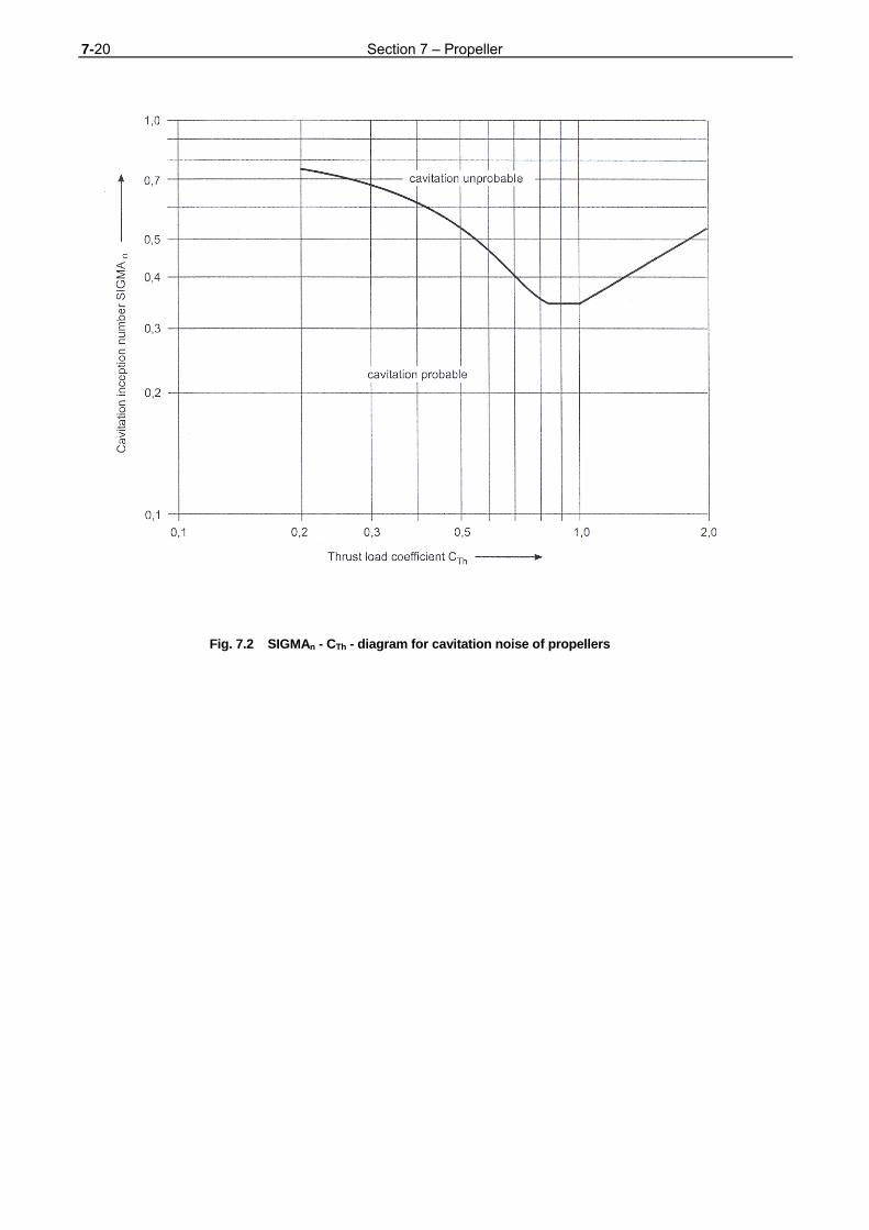
7-20 Section 7 – Propeller
Fig. 7.2 SIGMAn - CTh - diagram for cavitation noise of propellers
Section 8 – Torsional Vibrations 8-1
SECTION 8
TORSIONAL VIBRATIONS
A. General 1. Scope
The requirements of this Section apply to the
components of the main shafting system and to
essential equipment, compare Section 1, B.4.
2. Definitions
2.1 For the purposes of these Rules, torsional
vibration stresses are additional loads due to torsional
vibrations. They result from the alternating torque which
is superimposed on the mean torque.
2.2 The speed range in which the plant can be
operated continuously is the service speed range. It
covers the range between nmin (minimum speed) and
1,05 nN (nominal speed).
B. Calculation of Torsional Vibrations
1. A torsional vibration analysis covering the
torsional vibration stresses is to be submitted to TL for
examination. The following data shall be included in the
analysis:
- Equivalent dynamic system comprising individ-
ual masses and inertialess torsional elasticities
- Prime mover
engine design (in line, V-type, etc.)
rated power, rated speed
number of cylinders, firing order
cylinder diameter, stroke
stroke to connecting rod ratio
oscillating weight of one crank gear
- Vibration dampers, damping data
- Coupling, dynamic characteristics and damping
data
- Gearing data
- Shaft diameter of crankshafts, intermediate
shafts, gear shafts, thrust shafts and propeller
shafts
- Propellers
diameter, number of blades
pitch and expanded area ratio
- Natural frequencies with their relevant vibration
forms and the vector sums for the harmonics of
the engine excitation
- Estimated torsional vibration stresses in all
important elements of the system within the
service speed range
2. The calculations are to be performed both for
normal operation and for deviations from normal
operation due to irregularities in ignition. In this respect,
the calculations are to assume operation with one
cylinder without ignition.
3. Where the arrangement of the installation
allows various operation modes, the torsional vibration
characteristics are to be investigated for all possible
modes, e.g. in installations fitted with controllable pitch
propellers for zero and full pitch, with power take off for
loaded and idling condition of the generator unit, with
clutches for engaged and disengaged branches.
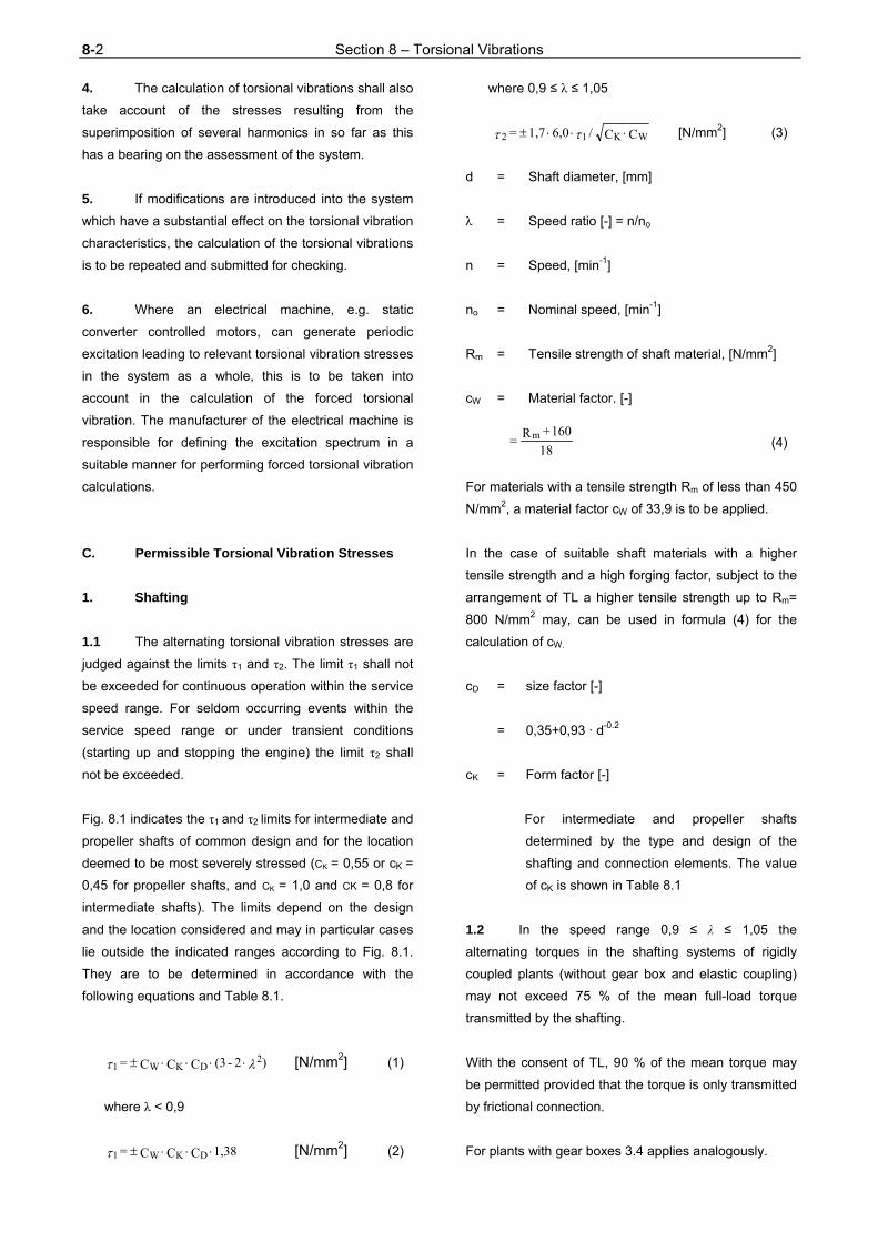
8-2 Section 8 – Torsional Vibrations
4. The calculation of torsional vibrations shall also
take account of the stresses resulting from the
superimposition of several harmonics in so far as this
has a bearing on the assessment of the system.
5. If modifications are introduced into the system
which have a substantial effect on the torsional vibration
characteristics, the calculation of the torsional vibrations
is to be repeated and submitted for checking.
6. Where an electrical machine, e.g. static
converter controlled motors, can generate periodic
excitation leading to relevant torsional vibration stresses
in the system as a whole, this is to be taken into
account in the calculation of the forced torsional
vibration. The manufacturer of the electrical machine is
responsible for defining the excitation spectrum in a
suitable manner for performing forced torsional vibration
calculations.
C. Permissible Torsional Vibration Stresses
1. Shafting
1.1 The alternating torsional vibration stresses are
judged against the limits τ1 and τ2. The limit τ1 shall not
be exceeded for continuous operation within the service
speed range. For seldom occurring events within the
service speed range or under transient conditions
(starting up and stopping the engine) the limit τ2 shall
not be exceeded.
Fig. 8.1 indicates the τ1 and τ2 limits for intermediate and
propeller shafts of common design and for the location
deemed to be most severely stressed (CK = 0,55 or cK =
0,45 for propeller shafts, and CK = 1,0 and CK = 0,8 for
intermediate shafts). The limits depend on the design
and the location considered and may in particular cases
lie outside the indicated ranges according to Fig. 8.1.
They are to be determined in accordance with the
following equations and Table 8.1.
) 2 - (3 C C C = 2DKW1 [N/mm2] (1)
where λ < 0,9
1,38 C C C = DKW1 [N/mm2] (2)
where 0,9 ≤ λ ≤ 1,05
C C / 6,0 1,7 = WK12 [N/mm2] (3)
d = Shaft diameter, [mm]
λ = Speed ratio [-] = n/no
n = Speed, [min-1]
no = Nominal speed, [min-1]
Rm = Tensile strength of shaft material, [N/mm2]
cW = Material factor. [-]
(4)
For materials with a tensile strength Rm of less than 450
N/mm2, a material factor cW of 33,9 is to be applied.
In the case of suitable shaft materials with a higher
tensile strength and a high forging factor, subject to the
arrangement of TL a higher tensile strength up to Rm=
800 N/mm2 may, can be used in formula (4) for the
calculation of cW.
cD = size factor [-]
= 0,35+0,93 · d-0.2
cK = Form factor [-]
For intermediate and propeller shafts
determined by the type and design of the
shafting and connection elements. The value
of cK is shown in Table 8.1
1.2 In the speed range 0,9 ≤ λ ≤ 1,05 the
alternating torques in the shafting systems of rigidly
coupled plants (without gear box and elastic coupling)
may not exceed 75 % of the mean full-load torque
transmitted by the shafting.
With the consent of TL, 90 % of the mean torque may
be permitted provided that the torque is only transmitted
by frictional connection.
For plants with gear boxes 3.4 applies analogously.
18
160 +Rm

Section 8 – Torsional Vibrations 8-3
Table 8.1 Form factors cK for intermediate and propeller shafts
cK Shaft type
1,00 Intermediate shafts
with integrally forged flanges and/or oil-press-mounted couplings
0,80
Intermediate shafts
with keyed mountings
Propeller shafts
in the forward (1) propeller shaft area
0,50 Intermediate shafts
with transverse holes
0,40 Intermediate shafts
with through slots
0,55 Propeller shafts
with integrally forged flanges in the after (2) propeller shaft area
0,55 Propeller shafts
with a propeller mounted by a method approved by TL in the aft (2) propeller shaft area
0,45
Propeller shafts
with tapered and keyed mountings and oil lubrication in the stern tube in the aft (2) propeller
shaft area
0,40 Propeller shafts
with grease lubrication in the stern tube in the aft (2) propeller shaft area
The part of propeller shafts outside the stern tube (the engine room area) is subject to the same cK factors as the intermediate
shaft.
(1) The forward propeller shaft area is the area inside the stern tube adjoining and lying forward of the after bearing
position. In constructions with shaft bossings, the forward are is that adjoining and lying forward of the position of the
after bossing bearing.
(2) The aft propeller area is the area inside the stern tube extending from the after stern tube bearing to the forward
supporting edge of the propeller hub. In constructions with shafts bossings, it is the area between the after bossing
bearing and the forward supporting edge of the propeller hub. The aft propeller shaft area shall have an axial extent of
at least 2,5 · d.
2. Crankshafts
2.1 Crankshafts have to be designed according to
TL Rules - Guidelines for the Calculation of
Crankshafts for I.C. Engines. The maximum alternating
torsional load on which this calculation is based shall
not be exceeded in any operating state within the
service speed range. 2.2 Torsional vibration dampers used to reduce the
stresses in the crankshaft must be suitable for use with
diesel engines. TL reserve the right to call for proof of
this.
Torsional vibration dampers shall be capable of being
checked for serviceability in the assembled condition or
shall be capable of being dismantled with reasonable
ease for checking.
3. Gears
3.1 In the service speed range 0,9 ≤ λ ≤ 1,05, no
alternating torque higher than 30 % of the mean torque
at nominal speed should normally occur in any gear
stage. The mean nominal torque is the value of the
maximum mean torque transmitted by the gear stage.
If the gearing is demonstrably designed for a higher
power, then, in agreement with TL, 30 % of the design
torque of the gear stage concerned may be taken as the
limit. Otherwise, the reference values for the permissible
bending stresses at the tooth root and for the tooth flank
(Hertzian) pressures are to be reduced accordingly.
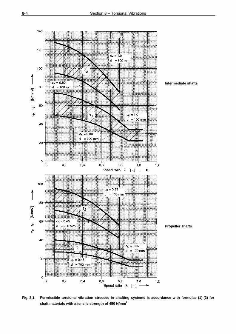
8-4 Section 8 – Torsional Vibrations
Intermediate shafts
Propeller shafts Fig. 8.1 Permissible torsional vibration stresses in shafting systems is accordance with formulas (1)-(3) for
shaft materials with a tensile strength of 450 N/mm2
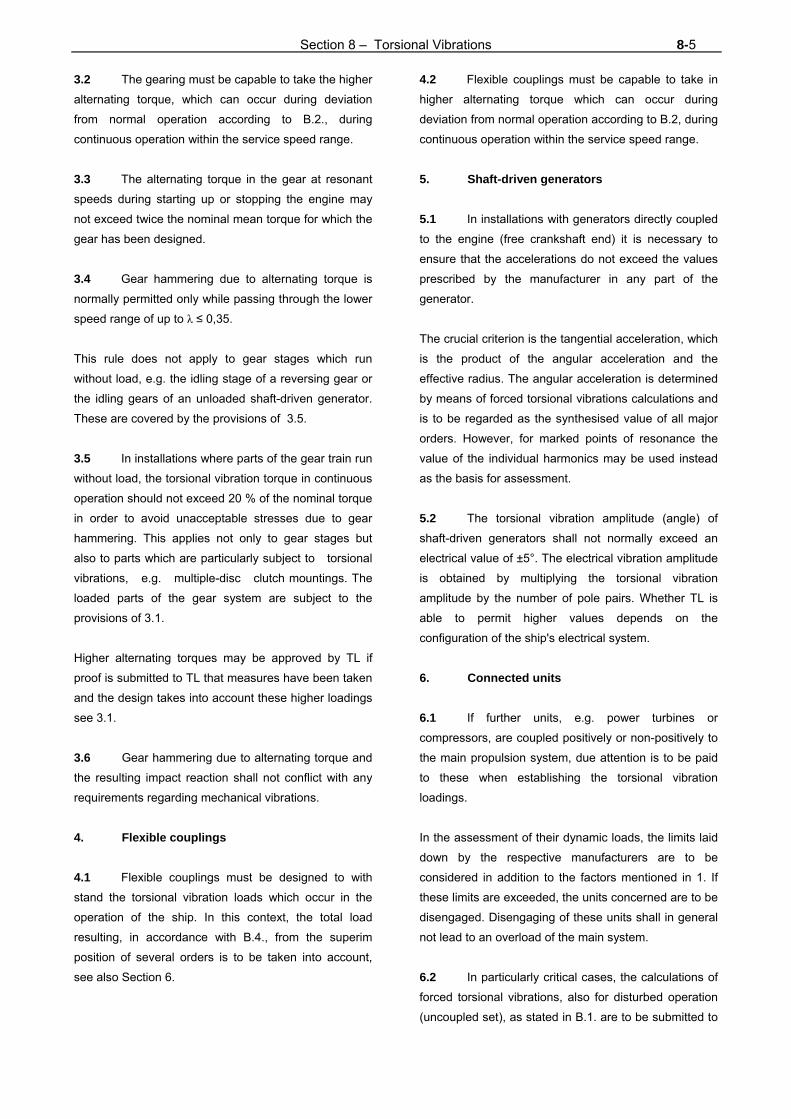
Section 8 – Torsional Vibrations 8-5
3.2 The gearing must be capable to take the higher
alternating torque, which can occur during deviation
from normal operation according to B.2., during
continuous operation within the service speed range.
3.3 The alternating torque in the gear at resonant
speeds during starting up or stopping the engine may
not exceed twice the nominal mean torque for which the
gear has been designed.
3.4 Gear hammering due to alternating torque is
normally permitted only while passing through the lower
speed range of up to λ ≤ 0,35.
This rule does not apply to gear stages which run
without load, e.g. the idling stage of a reversing gear or
the idling gears of an unloaded shaft-driven generator.
These are covered by the provisions of 3.5.
3.5 In installations where parts of the gear train run
without load, the torsional vibration torque in continuous
operation should not exceed 20 % of the nominal torque
in order to avoid unacceptable stresses due to gear
hammering. This applies not only to gear stages but
also to parts which are particularly subject to torsional
vibrations, e.g. multiple-disc clutch mountings. The
loaded parts of the gear system are subject to the
provisions of 3.1.
Higher alternating torques may be approved by TL if
proof is submitted to TL that measures have been taken
and the design takes into account these higher loadings
see 3.1.
3.6 Gear hammering due to alternating torque and
the resulting impact reaction shall not conflict with any
requirements regarding mechanical vibrations.
4. Flexible couplings
4.1 Flexible couplings must be designed to with
stand the torsional vibration loads which occur in the
operation of the ship. In this context, the total load
resulting, in accordance with B.4., from the superim
position of several orders is to be taken into account,
see also Section 6.
4.2 Flexible couplings must be capable to take in
higher alternating torque which can occur during
deviation from normal operation according to B.2, during
continuous operation within the service speed range.
5. Shaft-driven generators
5.1 In installations with generators directly coupled
to the engine (free crankshaft end) it is necessary to
ensure that the accelerations do not exceed the values
prescribed by the manufacturer in any part of the
generator.
The crucial criterion is the tangential acceleration, which
is the product of the angular acceleration and the
effective radius. The angular acceleration is determined
by means of forced torsional vibrations calculations and
is to be regarded as the synthesised value of all major
orders. However, for marked points of resonance the
value of the individual harmonics may be used instead
as the basis for assessment.
5.2 The torsional vibration amplitude (angle) of
shaft-driven generators shall not normally exceed an
electrical value of ±5°. The electrical vibration amplitude
is obtained by multiplying the torsional vibration
amplitude by the number of pole pairs. Whether TL is
able to permit higher values depends on the
configuration of the ship's electrical system.
6. Connected units
6.1 If further units, e.g. power turbines or
compressors, are coupled positively or non-positively to
the main propulsion system, due attention is to be paid
to these when establishing the torsional vibration
loadings.
In the assessment of their dynamic loads, the limits laid
down by the respective manufacturers are to be
considered in addition to the factors mentioned in 1. If
these limits are exceeded, the units concerned are to be
disengaged. Disengaging of these units shall in general
not lead to an overload of the main system.
6.2 In particularly critical cases, the calculations of
forced torsional vibrations, also for disturbed operation
(uncoupled set), as stated in B.1. are to be submitted to

8-6 Section 8 – Torsional Vibrations
TL. In such cases TL reserve the right to stipulate the
performance of confirmatory measurements, see D.,
also for disturbed operation.
D. Torsional Vibration Measurements
1. During the ship's sea trials, the torsional
vibrations of the propulsion plant are to be measured
over the whole operating range. Where measurements
of identical propulsion plants are available, subject to TL
agreement, further torsional vibration measurements
may be dispensed with. 2. Where existing propulsion plants are modified,
TL reserve the right to require a renewed investigation
of the torsional vibration characteristics.
E. Prohibited Ranges of Operation
1. In general, no operational restrictions are
allowed within the service speed range.
2. For special operational conditions, e.g. ignition
irregularities, restrictions from the engine manufacturer
are to be observed and to be displayed on instruction
plates, which are to be affixed to all engine control
stations.
F. Auxiliary Machinery
1. Essential auxiliary machinery must be
designed in a way that the service speed range is free
of unacceptable stresses due to torsional vibrations in
accordance with C.
2. Generators
2.1 For diesel generator sets with a mechanical
output of more than 150 kW torsional vibration
calculations must be submitted to TL for approval. They
must contain natural frequencies as well as forced
vibration calculations. The speed range 90 % to 105 %
of the nominal speed must be investigated under full
load conditions (nominal excitation). 2.2 For rigidly coupled generators (without elastic
coupling) the alternating torque in the input part of the
generator's shaft must not exceed 250 % of the nominal
torque.
It has to be proved that this limit can be kept within the
speed range 90 % to 105 % of the nominal speed.
Exceeding the limit of 250 % may be considered in
exceptional cases, provided that the generator's
manufacturer has designed the generator for a higher
dynamical torque.
3. Bow thruster
3.1 For bow thrusters as well as for other essential
auxiliary machinery driven by diesel engines with a
mechanical output higher than 150 kW, natural as well
as forced torsional vibration calculations must be
submitted to TL for approval. The torsional vibration
calculation must focus on the real load profile of the set. 3.2 For bow thrusters as well as for other essantial
auxiliary machinery driven by electrical motors the
manufacturer must ensure that relevant excitation
forces, e.g. propeller blade frequency, may not lead to
unacceptable torsional vibration stresses within the set.
In special cases TL may require the submission of
relevant calculations.

Section 9 – Machinery for Ships with Ice Classes 9-1
SECTION 9
MACHINERY FOR SHIPS WITH ICE CLASSES A. General
1. Notation B affixed to the Character of Classification
The machinery of naval ships strengthened for navi-
gation in drift ice in the mouth of rivers and in coastal
regions is designated after the Character of
Classification by the additional Notation B, provided that
the rules in B. are satisfied.
2. Measures for other conditions of navigation in ice
Measures for conditions of navigation in ice, different
from the conditions relevant for 1. will be defined by TL
case by case.
If other Class Notations are required by the Naval
Authority see TL Rules Chapter 4 - Machinery
Installations, Section 13.
B. Requirements for Notation B
1. Necessary Propulsion Power
The rated output of the main engines in accordance with
Section 3, A.3. must be such to cover the power
demand of the propulsion plant for the ice class
contitions under consideration and for continuous
service.
2. Necessary reinforcements
2.1 Propeller shafts, intermediate shafts, thrust shafts
2.1.1 General
The necessary propeller shaft reinforcements in
accordance with formula (1), in conjunction with the
formulae and factors specified in Section 5, C.3., apply
to the area of the aft stern tube bearing or shaft bracket
bearing from the forward end of the propeller cone or
the aft propeller shaft flange and up to a minimum axial
distance of 2,5 · d.
The diameter of the adjoining part of the propeller shaft
(beyond 2,5 d) but still within the stern tube may be
designed by applying an ice class reinforcement factor
reduced by 15 % as calculated by formula (2).
2.1.2 Reinforcements
dE = CEW · d (1)
= increased diameter of propeller, intermediate
or thrust shaft [mm]
d = Shaft diameter according to Section 5, C.3.
[mm]
CEW = Ice class strengthening factor, [-]
(2)
PW = Main engine power, [kW]
n2 = Propeller shaft speed in rev/min, [min-1]
m = Ice class factor, [-]
= 8
c = 0,7 for shrink fits in gears, [-]
= 0,71 for the propeller shafts of fixed-pitch
propellers,
1,0 n P
m 85 + 1 c = C 3
0,22
0,6W
EW

9-2 Section 9 – Machinery for Ships with Ice Classes
= 0,78 for the propeller shafts of
controllable pitch propellers
= 0,6 for intermediate and thrust
shafts
In the case of ducted propellers, the values of c can be
reduced by 10 %.
2.2 Coupling bolts, shrunk joints
When designing shrink fits in the shafting system and in
gearboxes, the necessary pressure per unit area pE
[N/mm2] is to be calculated in accordance with the
following formula (3).
(3)
+ sign following the root applies to conical shrink
joint without an axial stop to absorb astern
thrust.
- sign following the root if the conical shrink joint
has an axial stop to absorb astern trust.
cA = see Section 5
ce = 0,89 · CEW≥ 1,0 (4)
CEW, ce = ice class reinforcement factors in accordance
with formula (2) or (4) as applicable [-]
Other symbols in accordance with Section 5, D.4.
2.3 Propellers
2.3.1 General
The propellers of ships with ice class B must be made
of the cast copper alloys or cast steel alloys specified in
Section 7.
2.3.2 Strengthening
2.3.2.1 Blade sections
t = blade section thickness in accordance with
Section 7, C.3 [mm]
tE = Increased thickness of blade section, [mm]
= t if CEP ≤ CDyn
=
CEP = Ice class strengthening factor, [-]
(6)
= 0,62 for solid propellers
= 0,72 for controllable pitch propellers
z = Number of blades, [-]
CDyn = Dynamic factor [-] in accordance with
Section 7, formula (3).
Other terms in the formula same as for formula (2).
2.3.2.2 Blade tips
(7)
t1,0E = Strengthened blade tip, [mm]
t' = Increase in thickness, [mm]
= 10 for ice class B
D = Propeller diameter, [mm]
Cw = Material factor [N/mm2] in accordance with
Section 7, C.2, Table 7.1.
f A
T θ )T + Q c c( f + T θ = p
226e
2A
22
E
1,0 n P
m z 21 + 1 f = C 0,2
20,6w
EP
DynEPDyn
EP CCiftC
C
)t + D (0,002 Cw
500 =
1,0Et
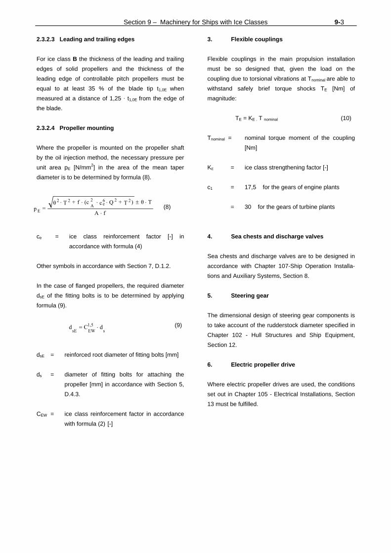
Section 9 – Machinery for Ships with Ice Classes 9-3
f A
T θ )T + Q c (c f + T θ = p
226e
2A
22
E
2.3.2.3 Leading and trailing edges
For ice class B the thickness of the leading and trailing
edges of solid propellers and the thickness of the
leading edge of controllable pitch propellers must be
equal to at least 35 % of the blade tip t1,0E when
measured at a distance of 1,25 · t1,0E from the edge of
the blade.
2.3.2.4 Propeller mounting
Where the propeller is mounted on the propeller shaft
by the oil injection method, the necessary pressure per
unit area pE [N/mm2] in the area of the mean taper
diameter is to be determined by formula (8).
(8)
ce = ice class reinforcement factor [-] in
accordance with formula (4)
Other symbols in accordance with Section 7, D.1.2.
In the case of flanged propellers, the required diameter
dsE of the fitting bolts is to be determined by applying
formula (9).
(9)
dsE = reinforced root diameter of fitting bolts [mm]
ds = diameter of fitting bolts for attaching the
propeller [mm] in accordance with Section 5,
D.4.3.
CEW = ice class reinforcement factor in accordance
with formula (2) [-]
3. Flexible couplings
Flexible couplings in the main propulsion installation
must be so designed that, given the load on the
coupling due to torsional vibrations at Tnominal are able to
withstand safely brief torque shocks TE [Nm] of
magnitude:
TE = KE . T nominal (10)
Tnominal = nominal torque moment of the coupling
[Nm]
KE = ice class strengthening factor [-]
c1 = 17,5 for the gears of engine plants
= 30 for the gears of turbine plants
4. Sea chests and discharge valves
Sea chests and discharge valves are to be designed in
accordance with Chapter 107-Ship Operation Installa-
tions and Auxiliary Systems, Section 8.
5. Steering gear
The dimensional design of steering gear components is
to take account of the rudderstock diameter specified in
Chapter 102 - Hull Structures and Ship Equipment,
Section 12.
6. Electric propeller drive
Where electric propeller drives are used, the conditions
set out in Chapter 105 - Electrical Installations, Section
13 must be fulfilled.
s1,5EWsE
dCd

Section 10 – Spare Parts 10-1
SECTION 10
SPARE PARTS
A. General 1. In order to be able to restore engine operation and manoeuvring capacity to the ship in the event of damage at sea spare parts for the main drive and the essential equipment (see Section 1, B.4.) are to be carried on board every ship, together with the necessary tools. These requirements are considered to be complied with if the range of spare parts corresponds to the following Tables considering the extent of the actually installed systems and components at the time of commissioning. 2. Depending on the design and arrangement of the engine plant, the intended service and operation of the ship, and also the manufacturer's recommendations, a different volume of spare parts may be agreed between the Naval Authority and TL. Where the volume of spare parts is based on special arrangements between the Naval Authority and TL, technical documentation is to be provided. A list of the relevant spare parts is to be carried on board. 3. In the case of propulsion systems and essential equipment which are not included in the following tables, the requisite range of spare parts is to be established in each individual case between Naval Authority, shipyard and TL. B. Volume of Spare Parts The volume of spare parts has to be in accordance with the following Tables. A = Unlimited range of service and Y B = All other ranges of service Explanations: Restricted International Service – Y This range of service is limited, in general, to operate along the coast, provided that the distance to the
nearest port of refuge and the offshore distance do not exceed 200 nautical miles. This applies also to operation in the North Sea and within enclosed seas, such as the Mediterranean Sea, the Black Sea, the Caspian Sea and waters with similar seaway conditions. Coastal Service - K50/K20 This range of service is limited, in general, to operate along the coasts, provided that the distance to the nearest port of refuge and the offshore distance do not exceed 50/20 nautical miles. This applies also to operation within enclosed seas, such as the Baltic Sea, Marmara Sea and gulfs with similar seaway conditions. Coastal Service – K6 This range of service is limited to operate along the coasts, provided that the distance to the nearest port of refuge and the offshore distance do not exceed 6 nautical miles. This area of service is restricted to operate in shoals, bays, haffs and firths or similar waters, where heavy seas do not occur. 1. Internal combustion engines For internal combustion engines, see Section 3, the volume of spare parts is defined in Tables 10.1 to 10.3. 2. Gears and thrust bearings For gears and thrust bearings, see Section 6, the vol-ume of spare parts is defined in Table 10.4. 3. Other spare parts For other spare parts for main and auxiliary engines the volume is defined in Table 10.5.

2-2 Section 2 - Class Designation C
Table 10.1 Spare parts for main engines (1), (4), (5)
Range of spare parts A B
Main bearings Main bearings or shells for one bearing of each size and type fitted, complete with shims, bolts and nuts
1
Main thrust block (integral)
Pads for "ahead" face of Michell type thrust block, or complete white metal thrust shoe of solid ring type
1 set 1 set
1 1
Connecting rod bearings
Bottom end bearings or shells of each size and type fitted, complete with shims, bolts and nuts, for one cylinders 1 set -
Trunk piston type: Gudgeon pin complete with bush/bearing shells and securing rings for one cyl-inder
1 set -
Cylinder liner Cylinder liner, complete with joint rings and gaskets 1 -
Cylinder cover Cylinder cover with full equipment and ready for installation, including gaskets 1 - Cylinder cover bolts and nuts, for one cylinder ¼ set -
Valves
Exhaust valves, with full equipment and ready for installation, for one cylinder 1 set 1 set Inlet valves, with full equipment and ready for installation, for one cylinder 1 set 1 set Starting air valve, with full equipment and ready for installation 1 1 Overpressure control valve, complete 1 1 Fuel injection valves of each type, ready for installation, for one engine (2) 1 set ¼ set
Hydraulic valve drive
High-pressure pipe/hose of each type 1 -
Piston: Trunk piston type
Piston of each type, ready for fitting, with piston rings, gudgeon pin, connecting rod, bolts and nuts
1 -
Piston rings Piston rings for one cylinder 1 set - Piston cooling Telescopic cooling pipes and fittings or their equivalent for one cylinder unit 1 set - Cylinder lubricator Complete lubricator, largest type, with drive 1 -
Fuel injection pumps
Fuel injection pump complete or, when replacement of individual components at sea is practicable, complete pump element with associated valves, seals, springs, etc.
1 -
Fuel injection pipes High pressure fuel pipe of each size and shape fitted, complete with couplings 1 -
Charge air system (3)
Auxiliary blower, complete including drive 1 - Exhaust-gas turbocharger: rotor complete with bearings, nozzle rings and
attached lube oil pump 1 set -
Suction and pressure valves of each type for one cylinder 1 set - Gaskets and packings
Special gaskets and packings of each type for cylinder covers and cylinder liners, for one cylinder - 1 set
Exhaust gas system (engine-related) Compensator of each type 1 -
(1) in the case of multi-engine installations, the minimum required spares are only necessary for one engine (2) a) engines with one or two fuel-injection valves per cylinder: one set of fuel valves, complete b) engines with more than two fuel injection valves per cylinder: two valves complete per cylinder plus a corresponding number of
valve parts (excluding the valve bodies) which make it possible to form a complete spare set by re-using the operational parts of the dismantled valves
(3) spare parts for exhaust-gas turbocharger and auxiliary blower may be omitted if emergency operation of the main engine after failure is demonstrably possible.
The requisite blanking and blocking arrangements for the emergency operation of the main engine are to be available on board.
(4) the necessary tools and equipment for fitting the required spare parts must be available on board (5) spare parts are to be replaced immediately as soon as they are "used-up"
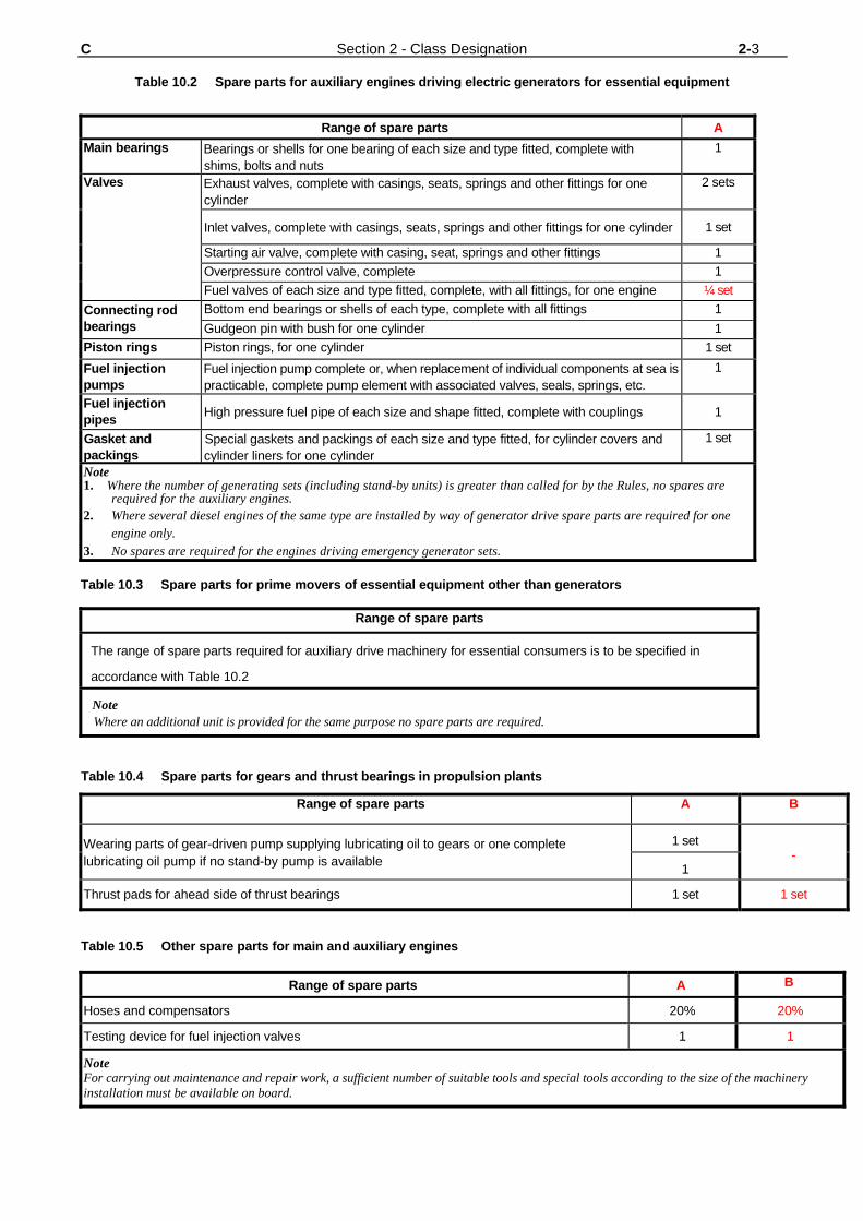
C Section 2 - Class Designation 2-3
Table 10.2 Spare parts for auxiliary engines driving electric generators for essential equipment
Range of spare parts A Main bearings Bearings or shells for one bearing of each size and type fitted, complete with
shims, bolts and nuts 1
Valves Exhaust valves, complete with casings, seats, springs and other fittings for one cylinder
2 sets
Inlet valves, complete with casings, seats, springs and other fittings for one cylinder 1 set
Starting air valve, complete with casing, seat, springs and other fittings 1 Overpressure control valve, complete 1 Fuel valves of each size and type fitted, complete, with all fittings, for one engine ¼ set
Connecting rod bearings
Bottom end bearings or shells of each type, complete with all fittings 1 Gudgeon pin with bush for one cylinder 1
Piston rings Piston rings, for one cylinder 1 set Fuel injection pumps
Fuel injection pump complete or, when replacement of individual components at sea is practicable, complete pump element with associated valves, seals, springs, etc.
1
Fuel injection pipes High pressure fuel pipe of each size and shape fitted, complete with couplings 1
Gasket and packings
Special gaskets and packings of each size and type fitted, for cylinder covers and cylinder liners for one cylinder
1 set
Note 1. Where the number of generating sets (including stand-by units) is greater than called for by the Rules, no spares are
required for the auxiliary engines. 2. Where several diesel engines of the same type are installed by way of generator drive spare parts are required for one
engine only. 3. No spares are required for the engines driving emergency generator sets. Table 10.3 Spare parts for prime movers of essential equipment other than generators
Range of spare parts
The range of spare parts required for auxiliary drive machinery for essential consumers is to be specified in
accordance with Table 10.2
Note Where an additional unit is provided for the same purpose no spare parts are required.
Table 10.4 Spare parts for gears and thrust bearings in propulsion plants
Range of spare parts A B
Wearing parts of gear-driven pump supplying lubricating oil to gears or one complete lubricating oil pump if no stand-by pump is available
1 set -
1
Thrust pads for ahead side of thrust bearings 1 set 1 set
Table 10.5 Other spare parts for main and auxiliary engines
Range of spare parts A B
Hoses and compensators 20% 20%
Testing device for fuel injection valves 1 1
Note For carrying out maintenance and repair work, a sufficient number of suitable tools and special tools according to the size of the machinery installation must be available on board.