
Rules for Classification and Construction VI...
42
Rules for Classification and Construction VI Additional Rules and Guidelines 10 Corrosion Protection 2 Guidelines for Corrosion Protection and Coating Systems Edition 2010
-
Upload
nguyencong -
Category
Documents
-
view
229 -
download
1
Transcript of Rules for Classification and Construction VI...

Rules for Classification and Construction VI Additional Rules and Guidelines
10 Corrosion Protection
2 Guidelines for Corrosion Protection and Coating Systems
Edition 2010

The following Guidelines come into force on 1 August 2010.
Alterations to the preceding Edition are marked by beams at the text margin.
Germanischer Lloyd AG
Head Office Brooktorkai 18, 20457 Hamburg, Germany
Phone: +49 40 36149-0 Fax: +49 40 36149-200
www.gl-group.com
"General Terms and Conditions" of the respective latest edition will be applicable (see Rules for Classification and Construction, I - Ship Technology, Part 0 - Classification and Surveys).
Reproduction by printing or photostatic means is only permissible with the consent of Germanischer Lloyd AG.
Published by: Germanischer Lloyd AG, Hamburg

Table of Contents
Section 1 General Fundamentals
A. Scope of Application .................................................................................................................. 1- 1 B. Limitations ................................................................................................................................. 1- 1 C. Definitions .................................................................................................................................. 1- 1 D. Symbols and Abbreviations Used .............................................................................................. 1- 1
Section 2 Structural Design
A. General ....................................................................................................................................... 2- 1
Section 3 Materials
A. General ....................................................................................................................................... 3- 1 B. Unalloyed and Low-Alloy Steels and Steel Castings ................................................................. 3- 1 C. Cast Iron ..................................................................................................................................... 3- 1 D. Stainless Steels and Stainless Steel Castings ............................................................................. 3- 2 E. Copper and Copper Alloys ......................................................................................................... 3- 3 F. Aluminium Alloys ...................................................................................................................... 3- 4 G. Contact Corrosion ...................................................................................................................... 3- 4
Section 4 Coatings
A. General ....................................................................................................................................... 4- 1 B. Preparation of the Surface .......................................................................................................... 4- 1 C. Selection of the Coating Materials ............................................................................................. 4- 5 D. Application of Coating Systems ................................................................................................. 4- 9 E. Competent Repair of Damage and Defects in Coating Systems during the Construction
Period ......................................................................................................................................... 4- 9 F. Testing, Acceptance and Documentation of the Coating Systems .............................................. 4- 10
Section 5 Metallic Coatings on Steel
A. Hot Galvanizing ......................................................................................................................... 5- 1 B. Thermal Spraying ....................................................................................................................... 5- 1
Section 6 Certification of Coating Work
A. General ....................................................................................................................................... 6- 1 B. Elements of the Certification ...................................................................................................... 6- 1 C. Certification ............................................................................................................................... 6- 2
VI - Part 10 GL 2010
Table of Contents Chapter 2Page 3

Section 7 Cathodic Corrosion Protection
A. General ........................................................................................................................................ 7- 1 B. External Protection through Sacrificial Anodes .......................................................................... 7- 2 C. Internal Protection through Sacrificial Anodes ........................................................................... 7- 5 D. External Protection through Impressed Current .......................................................................... 7- 6 E. Maintenance of the Cathodic Protection System ........................................................................ 7- 9 F. Documentation of the Cathodic Protection System ..................................................................... 7- 9
Section 8 Standards
A. Normative References ................................................................................................................. 8- 1 B. Guidelines of the Society of Naval Architects and Marine Engineers (STG) ............................. 8- 1 C. DVS Merkblätter (Work Sheets) ................................................................................................ 8- 2
Chapter 2 Page 4
Table of Contents VI - Part 10GL 2010

Section 1
General Fundamentals
A. Scope of Application
These Guidelines contain technical fundamentals on corrosion and the rules applying to corrosion protec-tion on ships, structural parts, components and struc-tures under maritime environmental and application conditions.
Under the condition that the corresponding boundary conditions are observed, they can also be applied to other systems, structural parts and components.
These Guidelines are intended to supplement the GL Rules for Hull Structures (I-1-1), Section 35 and the GL Rules for Coating of Ballast Water Tanks (VI-10-1) and for Corrosion Protection of Crude Oil Cargo Tanks (VI-10-3) which are limited to only those as-pects which are imperative from the classificatory point of view and which shall always be complied with for the construction of ships with GL Class.
National or international provisions and rules are to be observed in addition.
B. Limitations
Corrosion as a mechanism cannot be prevented en-tirely as such; it is merely possible to minimize the corrosion rates and the effects of the corrosion.
The aim should be to reduce the corrosion rate to an acceptable level for a certain system by means of corrosion protection measures, e.g. an appropriate selection of materials, application of the correspond-ing design principles, suitable coating systems or through cathodic protection. The result is that, with a high degree of probability, the specified lifetime of the structure is ensured and no corrosion damage will occur.
The corrosion and the corrosion rate depend on many different parameters. Application and environmental conditions, material properties, stress and strain states, as well as the effectiveness and efficiency of protec-tive measures all have an influence on corrosion.
Damage by corrosion can certainly be prevented. The principles and information given in these Guidelines are based on normative standards and values from experience which, applied correctly, will guarantee an adequate degree of corrosion protection for ships and components subjected to seawater and a marine at-mosphere.
However, this does not release the operators and de-signers from the obligation to assess properly the special features of each particular system, structural part or component and to consider the relevant corro-sion hazard. In particular, the corrosion protection measures which are applied, their maintenance and the servicing activities shall be coordinated to suit the component or the structure and also the specified lifetime.
In designing the corrosion protection, the specific contractual conditions and agreements between the purchaser and the manufacturer shall always be taken into account.
For the design of the corrosion protection, the relevant normative references shall also be considered. Upon request, GL can act in an advisory capacity.
C. Definitions
Terms and their explanations in respect of corrosion and corrosion protection are defined in ISO 8044, EN ISO 4618, ISO 12944, EN 12473 and DIN 81249.
For the terms "seawater" and "sea atmosphere", the terms "salt water" and "marine atmosphere" are also in common use.
D. Symbols and Abbreviations Used
AG = total area to be protected
AKSZ = area of a cathodic protection zone
AY = acrylic resin
DTZ = immersed zone
EP = epoxy resin
FB = shop primer
fB = loading factor
FVK (FRP) = fibre-reinforced plastic
IG = total protective current
IK (IC) = intercrystalline corrosion
VI - Part 10 GL 2010
Section 1 General Fundamentals Chapter 2Page 1–1
D
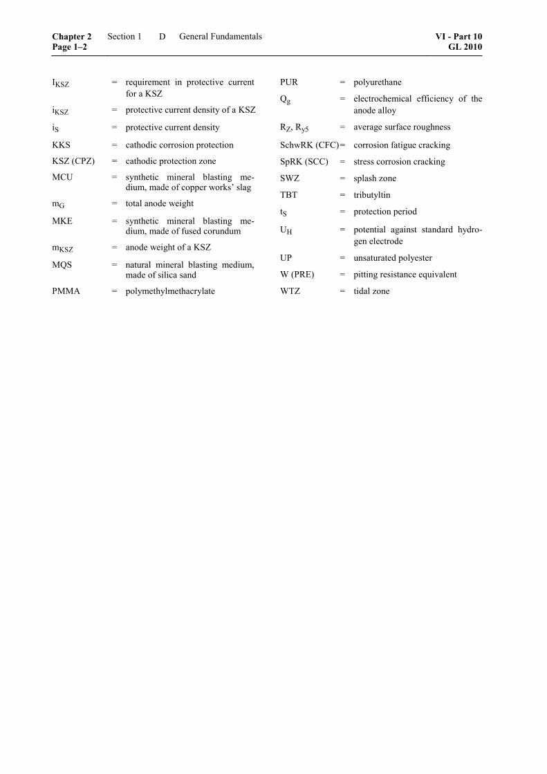
IKSZ = requirement in protective current for a KSZ
iKSZ = protective current density of a KSZ
iS = protective current density
KKS = cathodic corrosion protection
KSZ (CPZ) = cathodic protection zone
MCU = synthetic mineral blasting me-dium, made of copper works’ slag
mG = total anode weight
MKE = synthetic mineral blasting me-dium, made of fused corundum
mKSZ = anode weight of a KSZ
MQS = natural mineral blasting medium, made of silica sand
PMMA = polymethylmethacrylate
PUR = polyurethane
Qg = electrochemical efficiency of the anode alloy
RZ, Ry5 = average surface roughness
SchwRK (CFC) = corrosion fatigue cracking
SpRK (SCC) = stress corrosion cracking
SWZ = splash zone
TBT = tributyltin
tS = protection period
UH = potential against standard hydro-gen electrode
UP = unsaturated polyester
W (PRE) = pitting resistance equivalent
WTZ = tidal zone
Chapter 2 Page 1–2
Section 1 General Fundamentals VI - Part 10GL 2010
D

Section 2
Structural Design
A. General
Ships, systems and components should be designed with the aim of ensuring optimum corrosion protection through the application of suitable structural measures.
Amongst others, the following measures have proven their worth in practice:
– Points at which moisture tends to collect, thus facilitating the origination and propagation of corrosion, e. g. gaps and sumps, shall be avoided as far as possible.
– The structural design should be such that subsequent activities for the passive and active corrosion protection, such as surface pre-treatments, coating work, inspections and maintenance, can be performed in an optimum manner, e. g. by ensuring good accessibility.
– So-called "shadow effects", which impede the coating work (such as open, deep gaps) shall be avoided.
– Accumulations of condensed water in steel structural elements can be avoided by providing sufficient venting possibilities.
– The surfaces shall be designed to be as flat as possible. Any stiffeners, internal parts and
piping, etc. should, wherever possible, be arranged in areas less at risk from corrosion.
– The possibility of performing a proper cleaning and pickling, especially in the case of passivatable materials, e. g. austenitic steels, shall be provided after the welding process.
– Corrosion by impingement of drops can be avoided by using baffle plates.
– Interrupted welds, such as "chain intermittent welds", are only permissible in zones which are heat-insulated and free of condensed water (see also the GL Rules for Hull Structures (I-1-1), Section 19).
– Burrs and sharp edges should be rounded off, in order to facilitate the coating work and to increase the durability of the coating. The minimum radius should be 2 mm.
– Hollow components which are not accessible shall be sealed off completely and permanently, e. g. by welding them closed; in doing so, any applicable safety measures shall be taken into consideration.
– Mixed construction using different materials should, if possible, be avoided; otherwise suitable insulating measures shall be applied.
VI - Part 10 GL 2010
Section 2 Structural Design Chapter 2Page 2–1
A


Section 3
Materials
A. General
1. Field of application
The statements in this section shall be considered for the selection of materials and in the design of ship components and units, if the corrosion behaviour of the material in seawater or sea atmosphere represents a major criterion.
2. Material selection
The material shall be selected both according to de-sign-related aspects and under consideration of the expected corrosive stress. The number of different materials within one structure shall, in consideration of the statements given in this chapter, be limited as far as possible and the materials shall be matched accordingly.
3. Residues and contamination
Cinders, annealing colour, welding spatter, rust, rem-nants from machining, residues of coatings and dirt shall be removed if their presence is likely to impair the corrosion resistance or the corrosion protection.
4. Welded joints
The welding consumables shall be selected so that the free corrosion potential of the weld material is the same or a little positive in relation to the free corro-sion potential of the materials to be joined. The weld-ing rules issued by GL shall be observed.
5. Maintenance
During cleaning, it shall be ensured that the Metallic coatings or covering layers are not damaged or de-stroyed.
B. Unalloyed and Low-Alloy Steels and Steel Castings
1. Scope of application
These Guidelines apply for unalloyed and low-alloy steels and steel castings, as mentioned in the GL Rules for Steel and Iron Materials (II-1-2), Section 1 to 4.
2. Protective measures
2.1 Corrosion allowance
If only uniform surface corrosion is to be expected, or for sea atmospheres also shallow pit formation, a corrosion allowance can be provided in the component design. According to the literature, the corrosion al-lowance per year of planned service time should be:
– 0,21 mm for wetted surfaces
– 0,10 mm for components and structures which are exposed only to the sea atmos-phere.
For ships and equipment with GL Class, the corrosion allowances according to the GL Rules for Hull Struc-tures (I-1-1), Section 3, K., shall always be observed.
A prerequisite for uniform surface corrosion is a uni-formly descaled and cleaned surface without fouling. Furthermore, no erosion corrosion shall occur as a result of local flow conditions.
2.2 Passive or active corrosion protection
This refers to coatings and Metallic coatings (passive) as well as a KKS (active) in the sense of these Guide-lines. Such additional protective measures shall be used wherever selective corrosion can be expected, e. g. because of structural details.
C. Cast Iron
1. Scope of application
These Guidelines apply for cast iron types with spher-oidal graphite and laminated graphite, as mentioned in the GL Rules for Steel and Iron Materials (II-1-2), Section 5.
2. Protective measures
2.1 Corrosion allowance
If only uniform surface corrosion is to be expected, or at sea atmospheres also shallow pit formation, a corro-sion allowance can be used in the calculations for the component design. According to the literature, the corrosion allowance per year of planned service time should be:
VI - Part 10 GL 2010
Section 3 Materials Chapter 2Page 3–1
C

– 0,12 mm for wetted surfaces
– 0,06 mm for components and structures which are only exposed to the sea atmos-phere.
For ships and equipment with GL Class, the corrosion allowances according to the Rules for Classification and Construction shall be observed in all cases.
A prerequisite for uniform area corrosion is a uniform, cleaned surface with an intact and undamaged casting skin without fouling. Furthermore, no erosion corro-sion shall occur as a result of local flow conditions.
2.2 Passive or active corrosion protection
This refers to coatings and linings (passive) as well as a KKS (active) in the sense of these Guidelines. Such additional protective measures should be used wher-ever selective corrosion can be expected, e. g. because of structural details or irregularities in the casting surface.
D. Stainless Steels and Stainless Steel Castings
1. Scope of application
These Guidelines apply for stainless steels and stain-less steel castings of the types mentioned in the GL Rules for Steel and Iron Materials (II-1-2), Section 1, G., Section 2, E. and Section 4, F. as well as in the Rules for Special Materials for Naval Ships (II-1-6).
2. Protective measures
Stainless steels and stainless steel castings exhibit a passive surface state in seawater, as is the case in all media which are not too acidic. Accordingly, coating these types of steel is only recommended under spe-cial conditions. Depending on the composition and grain structure, stainless steels are sensitive to local corrosion, such as pitting and crevice corrosion.
2.1 Pitting and crevice corrosion
2.1.1 Alloy composition
Depending on the temperatures to be expected, steels with the following Pitting resistance equivalent in seawater are regarded as being resistant to pitting and crevice corrosion.
Table 3.1 Required pitting resistance equivalent for seawater impingement
Limiting temperature for pitting resistance
in seawater [°C]
Pitting resistance equivalent
W (min.)
40 35 25 30
10 25
The Pitting resistance equivalent (W) is calculated as follows:
a) For austenitic stainless steels alloy with more than 3 % molybdenum as well as nickel base al-loys:
W %Cr 3,3 %Mo 30 %N= + ⋅ + ⋅
b) For the austenitic-ferritic stainless steels X2CrNiMoN22-5-3 (1.4462):
W %Cr 3,3 %Mo 16 %N= + ⋅ + ⋅
c) For austenitic stainless steels alloy with less than 3 % molybdenum as well as for the austen-itic-ferritic steel X3CrNiMoN27-5-2 (1.4460):
W %Cr 3,3 %Mo= + ⋅
2.1.2 Cathodic corrosion protection
Through cathodic corrosion protection, pitting and crevice corrosion can be prevented, whereby in the case of crevice corrosion, the effect of the KKS is limited, depending on the crevice geometry. For the case of pitting corrosion, a reduction in potential to UH = – 0,1 V is sufficient for the austenitic and aus-tenitic-ferritic steels, and UH = – 0,3 V for the marten-sitic or nickel-martensitic CrNi, CrMo and CrNiMo steels.
Note
Uncoated stainless steels are not protected cathodi-cally if they are suitable for withstanding the corro-sion stress. Coated stainless steels shall be cathodi-cally protected in the submerged zone.
2.1.3 Design and workmanship
The following fundamental principles shall be ob-served:
– Crevices shall be avoided as far as possible. If this is not feasible, the crevice should be made as large as possible, i.e. the gap should be wider than it is deep and the width should be larger than 1 mm.
– Flanges shall, if applicable, be made of materi-als with a greater corrosion resistance.
Chapter 2 Page 3–2
Section 3 Materials VI - Part 10GL 2010
D

– Heat transmission paths should be avoided.
– Welds shall be executed in a technically compe-tent manner, e. g. root imperfections and a mate-rial sensitivization through incorrect temperature control shall be avoided.
– Weld joints shall be post-treated in a technically competent manner, e. g. through the removal of annealing colours, scale layers etc.
– Coarse mechanical grinding is not permissible.
– The surface should be as smooth as possible.
– Only suitable processing tools should be used (e. g. "stainless steel brush").
2.2 Intercrystalline corrosion (IC)
Steels that are not resistant to IC shall only be used in the solution-annealed state. Steels with a reduced carbon content (C = 0,03 %) as well as steels stabi-lized with titanium or niobium exhibit sufficient resis-tance against IC.
2.3 Stress corrosion cracking (SCC)
In seawater at temperatures above about 50 °C, chlo-rine-induced stress corrosion cracking can occur at austenitic stainless steels. At higher temperatures, steels with high contents of molybdenum and espe-cially nickel shall be selected; their suitability shall be checked in each individual case. A high corrosion resistance is exhibited by austenitic-ferritic steels, e. g. the material X2CrNiMoN22-5-3 (1.4462), because of their grain structure.
Martensitic steels tempered for high tenacity require a KKS. However, the protective potential should lie below – 0,5 V(UH) for hardness increases above 350 HV (e. g. through welding) or tenacities above 1 000 MPa, otherwise there is a risk of hydrogen em-brittlement.
2.4 Corrosion fatigue cracking (CFC)
In the case of a vibration stress, steps shall be taken to exclude local corrosion attack. On the one hand, molybdenum-containing steels shall be selected by preference and, on the other, a KKS should be in-stalled. Here too, the protective potential should not lie below – 0,5 V (UH) in the case of the higher-strength martensitic steels (Rm > 1 000 MPa).
E. Copper and Copper Alloys
1. Scope of application
These Guidelines apply for copper, for wrought cop-per alloys and for cast copper alloys, as mentioned in the GL Rules for Non-Ferrous Metals (II-1-3), Section 2. Oxygenic and oxygen-free types of copper as well as copper-zinc wrought and cast alloys with and with-out further alloying elements (except for CuZn20Al2 (2.0460)) are generally unsuitable for direct use in seawater.
2. Protective measures
The following aspects should be observed:
– There shall be a uniform surface condition with-out e. g. edges of cuts, surface damages or local fouling.
– For the formation of a favourable protective coating, commissioning with clean and well-aerated water is necessary.
– Care shall be taken to ensure that the protective layers cannot dry out and become brittle, e. g. during plant outages.
– In the area of application, there should be suffi-cient convection with flow rates exceeding 0,1 m/s.
– Regarding structural design Section 2 is to be observed.
– In the vicinity of the tidal zone, red bronze and tin bronze should not be used if possible, since there is a risk of pitting corrosion.
– The use of copper-aluminium alloys at tempera-tures above 60 °C is unfavourable. However, this does not apply, for alloys with a nickel ad-mixture, if an Al content > (8,5 + Ni/2)% is ob-served.
– Pipework should be designed for a flow rate of at least 0,8 m/s. The upper limit for the flow rate depends on the material and piping diameter. The following values shall not be exceeded, see Table 3.2.
VI - Part 10 GL 2010
Section 3 Materials Chapter 2Page 3–3
E

Table 3.2 Maximum flow rates for pipes made of seawater-resistant copper alloys
Material- Max. calculated flow rate [m/s]
Brief designation Number DN ≤ 40 DN > 40
CuZn20Al2 2.0460 2,8 3,0
CuNi10Fe1,6Mn CuNi10Fe1Mn
2.1972 2.0872
2,5 3,5
CuNi30Mn1Fe 2.0882 3,1 4,5
CuNi30Fe2Mn2 2.0883 4,5 6,0
F. Aluminium Alloys
1. Scope of application
These Guidelines apply for wrought and cast alumin-ium alloys, as mentioned in the GL Rules for Non-Ferrous Metals (II-1-3), Section 1.
2. Protective measures
For hull structures or components of zinc-free alumin-ium materials which are continuously submerged in seawater, cathodic protection with a protective poten-tial of less than – 0,55 V (UH) by sacrificial anodes is required. For zinc-containing aluminium materials, the necessary protective potential shall be determined in each individual case.
Cathodic protection is also recommended for materials which are subjected to the corrosion stress of the tidal zone.
For aluminium materials which are only exposed to spray water, corrosion protection is not necessary. As a possible corrosion protection measure, the electro-lytic anodizing of the aluminium surface has proven its worth for this area.
With aluminium materials, the danger of contact cor-rosion should always be considered.
In many cases, a coating is selected for aesthetic rea-sons or possibly as the basis for an antifouling system. The requirements for corrosion protection shall be observed with such applications.
For the underwater parts of ships and other structures made of aluminium alloys, anti-foulings based on copper oxide as the effective constituent shall not be used, since this can lead to corrosion damage of the substrate metal.
G. Contact Corrosion
The Table 3.3 provides information on the hazard of contact corrosion for various metallic materials with the same kind or different counterpart materials in seawater. Using the information given therein, it is possible e. g. to estimate the suitability or corrosion behaviour of bolted or riveted connections, whereby the area of the material to be assessed, in this case the bolt for example, shall be viewed as small in relation to that of the base material.
Chapter 2 Page 3–4
Section 3 Materials VI - Part 10GL 2010
G

Table 3.3 Influence of contact corrosion, based on DIN 81249
< 0 0 0 0 0 0
= 0 0 0 0 0 0
Tita
nium
and
T
itani
um A
lloys
> 0 0 0 0 0 0
< 0 0 0 + 0 0
= 0 0 0 + 0 0
Nic
kel
Allo
ys
> 0 0 0 + 0 0
< X
X
XX
0 XX
XX
= X
X
XX
0 X
X
Alu
min
ium
A
lloys
> X 0 X
X
0 X
X
< + X 0 ++
X
XX
= + 0 0 + 0 X
Cop
per
and
Cop
per
Allo
ys
> + 0 0 + 0 0
< ++
0 0 + 0 0
= + 0 0 0 0 0
Stai
nles
s Ste
els a
nd
Stai
nles
s Ste
el
Cas
tings
> + 0 + 0 0 0
< 0 XX
XX
+ XX
XX
= 0 X
XX
+ X
X
Mat
eria
l to
be a
sses
sed,
subg
roup
Una
lloye
d an
d Lo
w-
Allo
y St
eel a
nd S
teel
C
astin
gs a
nd C
ast I
ron
> 0 X
X + X 0
In c
onta
ct w
ith m
ater
ial
of th
e su
bgro
up
Una
lloye
d an
d Lo
w-A
lloy
Stee
ls a
nd
Stee
l Cas
tings
and
Cas
t Iro
n
Stai
nles
s Ste
els a
nd S
tain
less
Ste
el
Cas
tings
Cop
per a
nd C
oppe
r Allo
ys
Alu
min
ium
Allo
ys
Nic
kel A
lloys
Tita
nium
and
Tita
nium
Allo
ys
> Th
e ex
pose
d su
rfac
e ar
ea o
f the
mat
eria
l to
be a
sses
sed
is la
rge
in c
ompa
rison
to th
at o
f the
mat
eria
l with
whi
ch it
is p
aire
d.
= Th
e ex
pose
d su
rfac
e ar
ea o
f the
mat
eria
l to
be a
sses
sed
is a
bout
the
sam
e as
that
of t
he m
ater
ial w
ith w
hich
it is
pai
red.
< Th
e ex
pose
d su
rface
are
a of
the
mat
eria
l to
be a
sses
sed
is sm
all i
n co
mpa
rison
to th
at o
f the
mat
eria
l with
whi
ch it
is p
aire
d.
++
The
corr
osio
n of
the
mat
eria
l to
be a
sses
sed
is re
duce
d st
rong
ly.
+ Th
e co
rros
ion
of th
e m
ater
ial t
o be
ass
esse
d is
redu
ced.
0 Th
e co
rros
ion
of th
e m
ater
ial t
o be
ass
esse
d is
influ
ence
d to
a n
eglig
ible
ext
ent.
X
The
corr
osio
n of
the
mat
eria
l to
be a
sses
sed
is in
crea
sed.
XX
Th
e co
rros
ion
of th
e m
ater
ial t
o be
ass
esse
d is
incr
ease
d to
an
appr
ecia
ble
exte
nt.
VI - Part 10 GL 2010
Section 3 Materials Chapter 2Page 3–5
G


Section 4
Coatings
A. General
The coatings shall be suitable for the corresponding application, according to the specifications of the manufacturer. For the maritime sector, this necessi-tates a resistance against seawater, brackish water and harbour water and against the impurities they contain. The properties, structure and application of a coating system shall be documented and specified by the coating manufacturer. Information on the coating material, its processing and its suitability within the coating system shall be included in the product data-sheets. The selection, surface pre-treatment and ap-plication shall be carried out in accordance with the specifications and the instructions of the coating manufacturer.
In case, that not more stringent requirements are specified by the coating manufacturer, the following provisions shall be used as minimum standard, if not otherwise agreed separately.
B. Preparation of the Surface
In the following, the essential requirements for the surface pre-treatment of – unalloyed and low-alloy steels – cast iron – stainless steels – aluminium alloys – copper alloys – materials with metallic coatings of zinc or alu-
minium – wood – fibre-reinforced plastics (FRP)
are stated.
Before abrasive-blasting or mechanical grinding and before coating takes place, all oil and grease residues shall be removed from surfaces contaminated in this way. All other surfaces for which no abrasive -blasting or mechanical grinding is necessary should always be freed from oil, grease, dirt and other con-taminants by means of a high-pressure cleaning unit or through dry-ice blasting.
Solid blasting media shall conform with the require-ments set out in ISO 11124 or ISO 11126, respec-tively.
1. Surface preparation of unalloyed and low-alloy steels
For the surface preparation of ballast water tanks the GL Rules for Hull Structures (I-1-1), Section 35 are to be observed.
1.1 Abrasive-blasting
1.1.1 Purity
Within the scope of application of these Guidelines, all steel surfaces shall always be descaled in the pre-production phase (through blasting to surface quality grade "Sa 2½" or, for smaller areas, mechanical grinding) and provided with a suitable shop primer, unless otherwise agreed by contract.
Prior to further coating works, renewed surface preparation is needed. The surface quality grades specified in the corresponding coating mate-rial/system documentation of the manufacturer shall be complied with. If not otherwise specified shall the blasting area extend at least 25 mm into the adjacent coated surfaces.
A dry blasting process should be used.
1.1.2 Blasting agent
As the blasting agents, copper works' slag (MCU), fused corundum (MKE) as well as iron or steel blast-ing agents can be considered. The use of silica sand (MQS) shall be avoided.
The blasting agents shall be free of dust, salts or other impurities.
1.1.3 Roughness
The surface roughness Rz should have the roughness grade "medium" according to ISO 8503-1.
1.1.4 Repairing of surface defects
Welding spatter, rough-rolled ends, laminations, rolling flaws etc. which have only become apparent immediately before or during the blasting work shall be remedied. Edges and welding seams shall be treated according to Table 4.1 and 4.2 and transitions shall be gradual. Further specifications are given in the Shipbuilding and Repair Quality Standard of the IACS.
At points at which extensive repair work shall be carried out after blasting, the blasting shall be re-peated after the repair. At components or structural units which concern the classification sector, the Rules for Materials of GL shall be observed in addi-tion.
VI - Part 10 GL 2010
Section 4 Coatings Chapter 2Page 4–1
B

Table 4.1 Preparation of edges following the German Shipbuilding Standard ch
amfe
r
edge
s
(top
and
belo
w)
X
flash
re
mov
al
(f
rom
bel
ow)
X X X
X
SAW
CU
T O
R S
HE
AR
CU
T E
DG
ES
no
dres
sing
X X
X X X
X
X
X X
X
X
smoo
th fa
ce
of m
anua
l cut
X 1
X 1
X 1
X 1
X
X
X
cham
fer
ed
ges
(to
p an
d be
low
)
X 3 X
burr
re
mov
al
(f
rom
bel
ow)
X X X
X
TH
ER
MA
L C
UT
TIN
G E
DG
ES
slag
r
emov
al
X
X
X
X
X
X
X
X
X
X
X
X
X
X
X
X
X
WO
RK
CO
MPL
ET
ION
D
ESI
GN
AT
ED
AR
EA
Shel
l
Expo
sed
deck
s inc
l. de
ck o
utfit
s, su
pers
truct
ure
outs
ide
Vis
ible
are
as w
ithin
eng
ine-
, sto
re-,
serv
ice-
and
livi
ng-r
oom
s
Beh
ind
ceili
ngs,
unde
rnea
th in
sula
tion
and
clad
ding
With
in se
rvic
e ro
utes
, e.g
. alle
yway
s, pi
pe tu
nnel
s
Car
go h
olds
(dry
)
Car
go h
olds
(wet
/dry
)
Voi
ds, c
offe
rdam
s
Bal
last
wat
er ta
nks 4
Cru
de o
il ta
nks 2
Cha
ngea
ble,
slop
and
dirt
wat
er ta
nks
Che
mic
al ta
nks
Tank
s for
fres
h w
ater
, drin
king
wat
er
Boi
ler w
ater
tank
s, di
still
ate
tank
s
Tank
s for
fuel
oil,
hea
vy o
il
Tank
s for
lubr
icat
ing
oil,
hydr
aulic
oil
incl
. ser
vice
tank
s
Circ
ulat
ion
oil t
anks
1 Pr
ovid
ed th
e sc
ore
dept
h ex
ceed
ed 0
,5 m
m fo
r stre
ngth
rele
vant
par
ts o
r 1,0
mm
for o
ther
par
ts.
2 In
cas
e th
e C
lass
Not
atio
n C
TC
is re
ques
ted
the
Rul
es a
ccor
ding
to C
hapt
er 7
– C
orro
sion
Pro
tect
ion
of C
rude
Oil
Car
go T
anks
hav
e to
be
obse
rved
. 3
Dep
artu
res h
ave
to b
e ag
reed
bet
wee
n ow
ner a
nd y
ard.
4
Bal
last
wat
er ta
nks o
n ve
ssel
s bui
lt ac
cord
ing
to IM
O R
esol
utio
n M
SC.2
15(8
2) h
as to
be
prep
ared
acc
ordi
ng to
the
GL
Rul
es fo
r Hul
l Stru
ctur
es (I
-1-1
), Se
ctio
n 35
.
Chapter 2 Page 4–2
Section 4 Coatings VI - Part 10GL 2010
B

Table 4.2 Preparation of welding seams following the German Shipbuilding Standard
grin
ding
pl
ane
smoo
thin
g of
seam
su
rfac
es
rem
oval
of
all
spat
ters
X
X
X 2 X
X X
X
rem
oval
of
loos
e sp
atte
rs
X
X
X
X
X
X
X
X
X X
X
rem
oval
of
visi
ble
slag
in
clus
ion
X
X X
X
rem
oval
of
unde
rcut
1
X
X X
X
rem
oval
of
visi
ble
pore
s
X
X X
X
X
WE
LD
ING
SE
AM
S
slag
re
mov
al
X
X
X
X
X
X
X
X
X
X
X
X
X
X
X
X
X
Shel
l
Expo
sed
deck
s inc
l. de
ck o
utfit
s, su
pers
truct
ure
outs
ide
Vis
ible
are
as w
ithin
eng
ine-
, sto
re-,
serv
ice-
and
livi
ng-r
oom
s
Beh
ind
ceili
ngs,
unde
rnea
th in
sula
tion
and
clad
ding
With
in se
rvic
e ro
utes
, e.g
. alle
yway
, pip
e tu
nnel
s
Car
go h
olds
(dry
)
Car
go h
olds
(wet
/dry
)
Voi
ds, c
offe
rdam
s
Bal
last
wat
er ta
nks 4
Cru
de o
il ta
nks 3
Cha
ngea
ble,
slop
and
dirt
wat
er ta
nks
Che
mic
al ta
nks
Tank
s for
fres
hwat
er, d
rinki
ng w
ater
Boi
ler w
ater
tank
s, di
still
ate
tank
s
Tank
s for
fuel
oil,
hea
vy o
il
Tank
s for
lubr
icat
ing
oil,
hydr
aulic
oil,
incl
. ser
vice
tank
s
Circ
ulat
ion
oil t
anks
WO
RK
CO
MPL
ET
ION
D
ESI
GN
AT
ED
AR
EA
A
B
C
D
E F G
H I K
L
M
N
O
P Q
R
1 R
efer
als
o to
ISO
581
7 2
Dep
artu
res h
ave
to b
e ag
reed
bet
wee
n ow
ner a
nd y
ard.
3
In c
ase
the
Cla
ss N
otat
ion
CT
C is
requ
este
d th
e R
ules
acc
ordi
ng to
Cha
pter
7 –
Cor
rosi
on P
rote
ctio
n of
Cru
de O
il C
argo
Tan
ks h
ave
to b
e ob
serv
ed.
4
B
alla
st w
ater
tank
s on
vess
els b
uilt
acco
rdin
g to
IMO
Res
olut
ion
MSC
.215
(82)
shal
l be
prep
ared
acc
ordi
ng to
the
GL
Rul
es fo
r Hul
l Stru
ctur
es (I
-1-1
), Se
ctio
n 35
.
VI - Part 10 GL 2010
Section 4 Coatings Chapter 2Page 4–3
B

1.1.5 Environmental conditions
For blasting purposes, the surface temperature shall lie at least 3 °C above the dewpoint and the relative at-mospheric humidity should be a maximum of 90 %. To prevent impairments by dust or blasting agents, the blasting activities should not be performed at places near which coating work is being done or near which coatings have not yet dried properly.
1.2 Mechanical grinding
Mechanical grinding is limited to smaller areas on which coating damages have to be repaired or where, because of the local conditions, no blasting can be performed. A surface condition as per "St3", "Sa2½" or one that is in accordance with the specifications of the coating manufacturer shall be achieved.
The mechanical treatment shall not cause any exces-sive polishing or roughening of the surface. The grind-ing shall extend at least 25 mm into the adjacent coated surfaces if not otherwise specified.
1.3 Pressurized water blasting with solid blasting agents
Pressurized water blasting with solid blasting agents should be limited to the areas that cannot be processed according to 1.1. This work shall be performed ac-cording to an approved specification, which shall be matched to the coating system by the coating manu-facturer.
2. Surface preparation of cast iron
For cast iron as a coating substrate, the same prerequi-sites as for steel apply in principle. However, in con-trast to rolling scale, the relatively thin casting skin need not be removed. The surface roughness is greater than for steel.
3. Surface preparation of stainless steels
3.1 Cleaning
Blasting shall be performed with ferrite-free blasting agents (proportion of metallic iron: max. 0,1 %). The blasting agents shall not have been used on ferritic materials beforehand. All adherent welding spatter, welding beads and welding cinders shall be removed. Brushes, pick hammers, spatulas and scrapers shall be made of stainless austenitic steel. Non-metallic brushes are permissible.
Abrasive media shall be ferrite-free and shall not con-tain an insert of steel wire.
Abrasive disks or belts shall not have been used on ferritic components beforehand. For the purity not achieved by blasting, a metallic smooth surface on the basis of surface quality grade "St3" or "P St3" is re-quired.
Annealing colours shall generally be removed by pickling or blasting. Grinding is permissible in excep-tional cases. The pickling solution shall not contain any hydrochloric acid. After pickling, the surface shall be neutralized by thorough washing with fresh water, especially in crevices. As a matter of principle, it shall be ensured that components that are no longer to be subjected to surface treatment are protected against ferritic abrasion, e.g. during storage: rust films, sparks from flame-cutting, welding or grinding.
If foreign contamination cannot be removed by the above-mentioned procedures and agents, suitable measures shall be taken after agreement has been reached.
3.2 Roughness
For the primer, the average surface roughness Rz shall be 30 – 45 μm. In confined spaces for which this sur-face roughness can only be achieved with difficulty, owing to the polishing effect of the blasting agent, metal sheets with a defined surface roughness of 50 μm can also be used. This parts shall be cleaned thoroughly before the coating is applied, e.g. by dry-ice blasting.
For surface which are to remain uncoated, the rough-ness should be as low as possible.
The blasting agent grain size and shape shall be se-lected so that sharp-edged surface is attained for the components to be coated, and a smooth, fine surface for components which are to remain uncoated.
4. Surface preparation of copper alloys and of materials with metallic coatings of zinc or aluminium materials
The components shall be thoroughly cleaned and degreased. The cleaning procedure shall be coordi-nated with the coating manufacturer.
The following procedures are permissible:
– cleaning with cold detergent and subsequent washing with fresh water
– steam jet cleaning with dosing of chemicals
– high-pressure cleaning with dosing of chemicals
– light blasting
– dry-ice blasting
Immediately after cleaning/degreasing and drying, the components shall be treated with a wash primer or with a suitable coating material which acts as an adhe-sion promoter and finish coat at the same time.
Chapter 2 Page 4–4
Section 4 Coatings VI - Part 10GL 2010
B

5. Surface preparation of aluminium alloys
5.1 Degreasing
All surfaces shall be thoroughly degreased. For this purpose, chlorine-containing detergents shall be avoided, as they can lead to corrosion problems.
5.2 Cleaning
The cleaning procedure shall be compatible with the corresponding coating material.
5.2.1 Pickling
An acidic pickling solution shall be applied uniformly to all surfaces to be treated. After application, the detergent shall be left to act on the material surface for the reaction time specified by the manufacturer, which is usually 20 – 30 minutes. Then the surface shall be washed thoroughly with fresh water, until the pH value of the washing water corresponds to that of the fresh water.
5.2.2 Grit-blasting
Only ferrite-free special fused alumina shall be used as the blasting agent. Blasting agents which have already been used for metals other than aluminium shall be avoided, owing to the risk of pitting corrosion. The surface roughness Rz should lie between 25 and 50 μm. The prepared surfaces should be thoroughly freed from dust and coated as soon as possible, since the newly formed oxide layer tends to generate a po-rous hydrous covering layer under the influence of the weather.
5.2.3 Mechanical grinding
Mechanical grinding is limited to smaller areas at which coating damage has to be remedied or where, because of the local conditions, no blasting or pickling can be performed. A coarse-grained grinding disc should be used, in order to achieve a suitable surface condition in accordance with the specifications of the coating manufacturer. The blasting should extend at least 25 mm into the adjacent coated surfaces.
6. Surface preparation of wood
The surfaces of wooden parts shall be freed from all contaminants and, if applicable, from foreign layers, e.g. through:
– sanding
– vacuum-cleaning
– brushing off
The surfaces shall be treated with a suitable sealing primer. When applying the sealing primer and subse-quent coatings, the moisture content of the solid wood shall not amount to more than 15 %.
7. Surface preparation of fibre-reinforced plastics (FRP)
The following requirements apply only for surfaces which are to be treated with a coating after the com-ponent has been fully fabricated.
The surfaces shall be freed from all contaminants, especially release agents. The surface shall not be etched. Brief high-pressure washing with hot water and with/without dosing of chemicals is permissible to remove grease. The water temperature shall not ex-ceed 80 °C.
Prior to application of a coating, the surface shall be roughened by sanding (with sandpaper of grain 100 or finer). The gelcoat shall not be sanded off.
It is possible that the sanding dust adheres to the sur-faces, for instance through electrostatic forces, and so it shall be removed by suitable means (e.g. blowing it off with ionized air). If necessary, a wash primer shall be applied after the roughening. The instructions in the GL Rules for Non-metallic Materials (II-2) shall also be observed.
C. Selection of the Coating Materials
1. Shop primers
The requirements for shop primers in respect of corro-sion protection are set out in the GL Rules for Hull Structures (I-1-1), Section 35.
The shop primers used particularly in shipbuilding (for GL Class) shall be approved by GL. For these shop primers, the requirements set out in the GL Rules for General Requirements, Proof of Qualifications, Ap-provals (II-3-1), Section 6, shall apply in addition.
If a shop primer shall be used in combination with a corrosion protection coating for sea water ballast tanks the GL Rules for Coating of Ballast Water Tanks (VI-10-1) are to be observed.
2. Corrosion protection systems
Coating materials and coating systems shall be se-lected and applied according to the effective interna-tional rules as well as environmental and application-related conditions. Suitable coating systems for the use in cargo tanks on bulk carriers and for the outer shell of steel ships are set out in Table 4.3. Their suit-ability shall in each case be guaranteed by the coating manufacturer, and evidence thereof shall be provided on request. The most important data of a coating mate-rial shall be documented according to STG Guideline No. 22161. For the selection, the applicable statutory
–––––––––––––– 1 In case of documentation of data of coatings for ballast water
tanks the GL Rules for Hull Structures (I-1-1), Section 35 apply.
VI - Part 10 GL 2010
Section 4 Coatings Chapter 2Page 4–5
C

conditions and technical rules concerning work, fire and environmental protection shall be observed by the user.
The selection of a coating system for a certain case should preferably be based on practical experience with similar cases. Coating systems which are subject to strong dynamic or elongation stresses, as can occur particularly on ships of higher-strength fine-grained structural steels, or which have to withstand high temperature stresses, shall be especially suitable for withstanding such stresses.
In addition to the necessary practical tests, the corro-sion protection effectiveness of coatings can be as-sessed on the basis of laboratory tests (see GL Rules for Hull Structures (I-1-1), Section 35). Moreover, in the case of underwater coatings, the compatibility with the cathodic corrosion protection procedure as per STG Guideline No. 2220 or an equivalent procedure should be verified.
Fig. 4.1 shows two typical coating systems for alumin-ium structures.
3. Special coatings
3.1 General
The coatings and coating materials mentioned in this section go beyond the scope of normal coating sys-tems for corrosion protection. With regard to applica-tion method, application case or suitability, they can only be used in a very specialized manner or only for certain areas.
3.2 Soft coatings
These solvent-free coating materials are based on wool fats, greases, mineral oils and/or waxes. They are used for corrosion protection coatings, for example in water ballast tanks2, by spraying in film thicknesses up to 2 mm. Because in such areas it is often only possible to remove the loose rust, these types are es-pecially suitable for cases of repair. However, where strong water movements can be expected other coat-ings should be given preference.
Since they do not contain any solvents, these coatings can be exposed to water immediately after their appli-cation. The disadvantage of these products is that the coatings remain relatively soft. To permit a proper walk-in inspection, all the necessary measures and safety precautions shall be taken. When flooding and freeing the tanks, it shall be ensured that no constitu-ents of the soft coating pass out of the ship into the sea. Soft coatings are not approved for ballast water tanks in ship newbuildings, and in the case of repair they are not considered when determining the survey intervals.
–––––––––––––– 2 Use of soft coatings in ballast water tanks may be restricted.
Reference is made to the GL Rules for Hull Structures (I-1-1), Section 35.
3.3 Repair coatings
Repair coatings are understood as being coatings which are preferred for the repair/renewal of the inter-nal protection, e.g. of seawater ballast tanks on older ships. They are semi-hard coatings with a strong in-hibiting effect. It should be possible to achieve a sur-face preparation which suffices for the application e.g. through pressurized water blasting based on STG Guideline No. 2222 or by mechanical surface prepara-tion with cleaning.
Such coatings can be examined by GL with regard to their special suitability for the case in question. Fol-lowing a successful practical test of such a system, a product approval is issued. When repair coatings with a product approval are used in areas of interest for the class, e.g. in the ballast water tanks, the GL Rules for Classification and Surveys (I-0-0), shall be observed in addition.
3.4 Fibre-reinforced plastics (FRP)
Solvent-free plastics which are reinforced with glass flakes, fibres, mats, fabrics and fleeces and made on the basis of unsaturated polyester (UP), epoxy resin (EP) and polyurethane (PUR) provide very abrasion-resistant high-build coatings of high density. Applica-tion is by spraying or using a spatula and inserting glass mats, fabrics or fleeces. Depending on the stress to be withstood, the number and thickness of insert layers can vary. The film thickness of the coatings can range up to several millimetres.
For the surface preparation, grit-blasting with the surface quality grade "Sa2½" is required. Shop prim-ers are not suitable as the substrate.
The special areas which are coated with these systems include e.g. the alternating submersion zones of off-shore structures as well as the protective shields of electrical corrosion protection equipment or hull parts of ice-going ships.
3.5 Deck coverings
Deck coverings in the sense of these Guidelines are coatings which are distinguished by very good corro-sion protection as well as a high abrasion resistance and anti-skid effect. They are mainly applied to the strongly frequented work surfaces in outside areas. The coatings have a total dry film thickness of 2 – 20 mm. The binding agent is based on solvent-free polyurethane (PUR), epoxy resin (EP), acrylic resin (AY) or polymethylmethacrylate (PMMA).
The surface preparation shall be undertaken by grit-blasting to surface quality grade "Sa2½". To protect the grit-blasted steel and to improve the adhesion of the coatings, a primer shall be applied. The heavily loaded coating material is applied in one or more layers, mainly by using a spatula. The anti-skid effect of the coating is achieved by scattering or working mineral materials of varying grain sizes and shapes into the wet layer.
Chapter 2 Page 4–6
Section 4 Coatings VI - Part 10GL 2010
C

At a concluding step, the surface is sealed.
To a certain degree, specially modified as-phalt/bitumen combinations are also used as deck coverings. In film thicknesses ranging between 25 and 50 mm, the coverings are armoured with expanded metal or gratings to improve the load-bearing capac-ity. Such coverings offer good corrosion protection, but exhibit the disadvantages of having thermoplastic properties and excessive weight.
3.6 Linings
Organic linings for cargo tank systems of product carriers shall be in accordance with DIN EN 14879-4.
The constructive design of metallic structural elements shall be in accordance with DIN EN 14879-1 or DIN 2874, respectively.
Linings with laminates of hard or soft rubber are used for the cargo tanks of product tankers for special car-goes, such as phosphoric acid. The surface shall be prepared by abrasive-blasting to surface quality grade "Sa 2½". This is followed by the application of a spe-cial primer for the temporary protection of the steel surface. After the preparation work in the tank has been completed, the lining is applied under a con-
trolled climate by bonding and welding the laminate strips. The self-vulcanization of the linings occurs, depending on the type of rubber, within a few weeks or months at temperatures of 20 – 250 °C.
The fittings, valves and piping belonging to the cargo loading/unloading system are vulcanized at the work-shop in closed autoclaves under pressure and at in-creased temperatures.
Furthermore, there are also solvent-free rubber-modified urethane coatings which are applied with special high-pressure spraying equipment in thick-nesses of 1 – 5 mm.
4. Approval of coatings
For all coating systems, it is possible to apply to GL for an approval. Here it is necessary to provide suffi-cient evidence to GL that the coating material is suit-able for the intended purpose. A written application shall be submitted to GL. After successful examina-tion of the product datasheets, coating specifications and suitability documentation appended to the applica-tion, e.g. references and relevant test results etc., a certificate is issued by GL. Coating materials for sea-water ballast tanks as per the GL Rules for Hull Struc-tures (I-1-1), Section 35, shall be approved.
��������������� ���������������������������������
�������������������������� ����!����
�� "#�������$�����
%������&��'(���
�� "#��������������
%��������� ������������
��������������������������������������)��
�� "#������� �������$�����
%������&��������#
�� "#�������*������
%��������� ������������
Fig. 4.1 Typical coating systems for aluminium structures
VI - Part 10 GL 2010
Section 4 Coatings Chapter 2Page 4–7
C
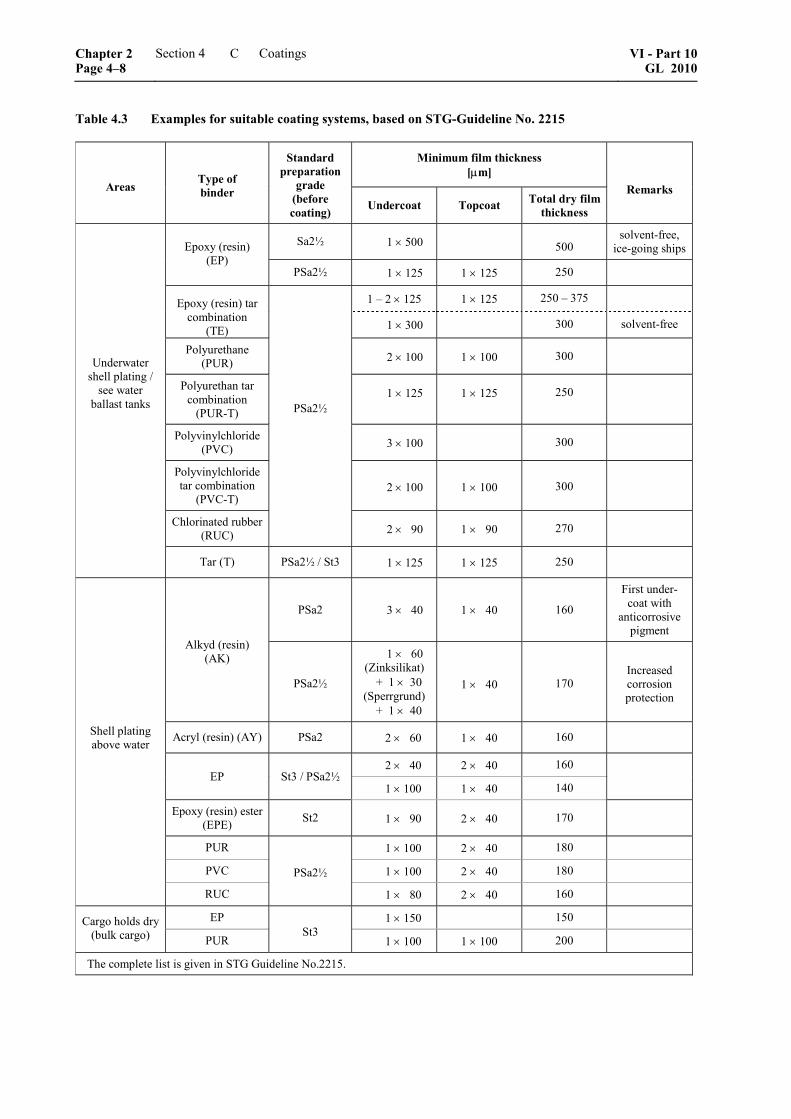
Table 4.3 Examples for suitable coating systems, based on STG-Guideline No. 2215
Minimum film thickness [μm]
Areas Type of binder
Standard preparation
grade (before coating) Undercoat Topcoat Total dry film
thickness
Remarks
Sa2½ 1 × 500 500 solvent-free,
ice-going ships Epoxy (resin) (EP)
PSa2½ 1 × 125 1 × 125 250
1 – 2 × 125 1 × 125 250 – 375 Epoxy (resin) tar combination
(TE) 1 × 300 300 solvent-free
Polyurethane (PUR) 2 × 100 1 × 100 300
Polyurethan tar combination
(PUR-T)
1 × 125 1 × 125 250
Polyvinylchloride(PVC) 3 × 100 300
Polyvinylchloride tar combination
(PVC-T) 2 × 100 1 × 100 300
Chlorinated rubber (RUC)
PSa2½
2 × 90 1 × 90 270
Underwater shell plating /
see water ballast tanks
Tar (T) PSa2½ / St3 1 × 125 1 × 125 250
PSa2 3 × 40 1 × 40 160
First under- coat with
anticorrosive pigment
Alkyd (resin) (AK)
PSa2½
1 × 60 (Zinksilikat) + 1 × 30
(Sperrgrund) + 1 × 40
1 × 40 170 Increased corrosion protection
Acryl (resin) (AY) PSa2 2 × 60 1 × 40 160
2 × 40 2 × 40 160 EP St3 / PSa2½
1 × 100 1 × 40 140
Epoxy (resin) ester (EPE) St2 1 × 90 2 × 40 170
PUR 1 × 100 2 × 40 180
PVC 1 × 100 2 × 40 180
Shell plating above water
RUC
PSa2½
1 × 80 2 × 40 160
EP 1 × 150 150 Cargo holds dry (bulk cargo) PUR
St3 1 × 100 1 × 100 200
The complete list is given in STG Guideline No.2215.
Chapter 2 Page 4–8
Section 4 Coatings VI - Part 10GL 2010
C

D. Application of Coating Systems
Special attention has to be paid if application shall be carried out for ballast water tanks. The relevant re-quirements are set out in the GL Rules for Hull Struc-tures (I-1-1), Section 35.
1. General requirements
– Before coating work commences, all surfaces shall be kept dust-free.
– Any scaffolding or stages which may be neces-sary shall, as far as possible, be arranged so that the surfaces to be coated can be processed con-tinuously (e.g. free-standing scaffold). If heating units are used, the exhaust fumes of the power generators shall be vented to the outside air; they shall not be allowed to mix with the heating air and precipitate on the surfaces to be coated.
– Unless otherwise agreed, the coating work shall commence on the prepared surfaces within four hours of the abrasive-blasting or mechanical grinding.
– The corresponding drying or curing times be-tween the individual layers shall comply with the manufacturer’s instructions, with due con-sideration of the environmental conditions.
– During the application of the various layers, all critical areas – such as edges, corners, welds, brackets, bolts and nuts – shall be stripe-coated, in order to ensure compliance with the minimum film thickness and a proper sequence of layers.
– The maximum thickness should, if not otherwise stated by the paint manufacturer, not be higher than three times the nominal thickness.
– The surface temperature should be less than 30 °C, but at least 3 °C above dewpoint, and the air temperature should, unless otherwise permit-ted by the coating manufacturer, be higher than 5 °C.
– The relative atmospheric humidity shall attain a maximum of 90 % for systems on epoxy resin basis and a maximum of 95 % for moisture-curing polyurethane systems. In practice, the following rule has proven its worth:
– If surface temperature and dewpoint are not measured at prescribed intervals, application shall only take place up to a relative atmos-pheric humidity of max. 85 %; if both pa-rameters are measured at intervals to be laid down, application may also take place at a higher relative atmospheric humidity.
– The first measurement shall be carried out before application commences. The intervals for further measurements shall be varied de-pending on the climatic conditions and their changes.
– No coating should be applied if a change of weather is to be expected such that the specified environmental parameters cannot be complied with over the next 2 hours after completion of the coating work.
As a matter of principle, the requirements as per ISO 12944-7 should also be observed for this area.
2. Spraying
Each layer shall be applied to the entire surface so that a uniform and closed coating is achieved. Defects in the coating which impair the corrosion protection effect shall be repaired before the next layer is ap-plied.
3. Painting with brush or roller
At points where, because of the local conditions, no spraying is possible, the coating shall be applied by painting with a brush or roller. The tool and the coat-ing material (for roller application) shall be suitable for the intended purpose.
4. Storage of coating materials
If no other requirements are stipulated by the manu-facturer of the coating materials, storage temperatures between 5 and 30 °C shall be observed for the materi-als. The materials shall not be stored for longer than permissible; the manufacturer’s instructions shall be observed.
5. Approval of coating shops
Coating shops can receive GL approval. As a prereq-uisite, the coating shop shall ensure, through personnel with suitable training and equipment that is in good working condition, that the demands set for the proc-essing of the coating materials are satisfied. An exist-ing quality management system with defined working sequences and the envisaged company-internal quality checks shall be verified. The examination of the con-ditions existing on site, with a positive result, shall be viewed as a fundamental requirement. This examina-tion shall be carried out before work starts; spot checks should also be made during the application process, to confirm the initial conditions. If all re-quirements are met and if the examinations yield a positive result, a certificate is issued by GL.
E. Competent Repair of Damage and Defects in Coating Systems during the Construc-tion Period
1. General
A classification of coating damage can take place according to STG-Guideline No. 2221, for example. The repair work shall always be suitable for the coat-ing system intended for the corresponding area, in-cluding the surface preparation.
VI - Part 10 GL 2010
Section 4 Coatings Chapter 2Page 4–9
E

2. Insufficient film thickness
Surfaces at which the film thickness is insufficient shall be cleaned thoroughly and, if necessary, sanded down. Then a compatible coating shall be applied until the required film thickness is attained. The transitions to the original coating shall be gradual.
3. Contaminated surfaces
Contaminated surfaces which are to be coated further, should be prepared anew as per B.
4. Coating damage without exposed metal surface
The affected areas of the surface shall first be cleaned and degreased as per B. In addition, it is necessary to attain smooth transitions by sanding the edge zones, in order to achieve as uniform a surface as possible. Many two-component coatings have a retouching interval; for this reason, if this interval has elapsed, additional edge zones shall be sanded or roughened in the intact area, to achieve perfect adhesion in the tran-sition zone.
5. Coating damage with exposed metal sur-face
The conditions of the material or the systems in re-spect of surface preparation, the application data for each individual layer, etc. shall be observed as per specification. For the adjacent coating areas, the re-quired procedure is set out in 4.
6. Repair of defective areas in sea water bal-last tanks according to IMO Resolution MSC.215(82)
If defective areas in sea water ballast tanks occur, special measures are to be observed as set out in the GL Rules for Hull Structures (I-1-1), Section 35.
F. Testing, Acceptance and Documentation of the Coating Systems
For Coating Systems applied according to IMO Reso-lution MSC.215(82) special measures for the testing, inspection and documentation apply as set out in the GL Rules for Hull Structures (I-1-1), Section 35.
1. Testing
The surface preparation of a component or a structure should be checked as follows before the coating work commences:
– Check of the required roughness profile (visual inspection or contact stylus method)
– Testing for soluble salts and other non-visible impurities (see ISO 8502) for high-quality coat-ing systems, e.g. for cargo tanks and seawater ballast tanks
Within the scope of the application process, each indi-vidual coating that is applied, and subsequently the entire coating system, shall be tested as follows:
– Visual inspection for uniformity, colour, cover-ing power, curing and possible defects (e.g. cracks, flaking, craters, etc.)
– Coating thickness measurement for compliance with the required target film thickness or mini-mum film thickness
– Coating systems for cargo tanks of chemical and product tankers shall be tested additionally with low-voltage or high-voltage units to ensure that they are free of pores.
– In special cases, a test of adhesive strength (see ISO 2409 or ISO 4624) is also possible.
There is the possibility, that control areas as per ISO 12944-7 will be provided at the object in ques-tion.
The scope, number and position of these control areas shall be agreed upon by the parties involved before the coating work commences.
2. Acceptance and documentation
For the acceptance (see STG Acceptance Protocol) of prepared surfaces and coating systems in all outside areas, water-containing tanks and cargo spaces, the applicator shall invite representatives of not only the shipyard but also of the coating material supplier and the ship owner to attend. In case of seawater ballast tanks, and for IW ships also the underwater part of the ship's outer shell, an acceptance inspection has to be carried out by the GL Surveyor.
The applicator shall compile the documentation and shall deliver this to the yard and, if applicable, to the other participants. The documentation shall provide evidence of the checks and acceptance tests as well as the conditions prevailing during the processing, in-cluding data on the coating materials which were used.
Chapter 2 Page 4–10
Section 4 Coatings VI - Part 10GL 2010
F

STG-Abnahme-Protokoll für den Verarbeiter STG-Acceptance-Protocol for Applicator
Firma: Company
Inspektor: Inspector
Datum: Date
Objekt: Object
Werft: Yard
Bereich: Area
Oberflächenvorbereitung gemäß Beschichtungsplan: Surface preparation acc. to coating plan
IST: act.
Abnahme: Acceptance
ja yes
nein no
Beschichtungs-System gemäß Beschichtungsplan: Coating system acc. to coating plan
Schichtdicken: Film thickness
von μm from micr.
bis μm to micr.
mittel μm average micr.
Oberflächenbeschaffenheit: Surface condition
Abnahme: Acceptance
ja yes
nein no
Bemerkungen: Remarks
Unterschriften der Teilnehmer Signatures of participants
Verarbeiter / Applicator Werft / Yard Reederei / Owner Beschichtungsstoff-Lieferant / Coating material supplier
Verteiler: Distribution
Werft / Beschichtungsstoff-Lieferant / Reederei Yard / Coating material supplier / Owner
VI - Part 10 GL 2010
Section 4 Coatings Chapter 2Page 4–11
F


Section 5
Metallic Coatings on Steel
A. Hot Galvanizing
Metallic coatings by hot galvanizing shall comply with the requirements set out in ISO 1461. Hot-galvanized components should always be protected additionally by a coating (duplex coating).
B. Thermal Spraying
1. Surface preparation and application conditions
The surface preparation of the steel surfaces shall comply with the requirements set out in Section 4, B.1. Further notes and recommendations are given in EN 13507 "Pretreatment of surfaces for thermal spraying".
With regard to the application conditions, the following points shall be observed:
– The interval between preparation and spraying shall be selected so that the surface to be coated remains clean and dry and does not visibly oxidize. This interval should be less than 4 hours.
– The steel temperature shall lie at least 3 °C above dewpoint.
2. Materials for metallic coatings
As suitable materials for metal spraying,
– aluminium: Al99,5 and
– Al-Mg alloy: AlMg5
as per ISO 14919 or an equivalent quality grade can be considered.
The following information shall be available with regard to the filler metal that is used:
– material datasheet
– material test certificate
– manufacturer's designation
– standard used
– production or batch number
– chemical analysis
– wire diameter
– net weight
– production date
3. Spraying technique
– Each layer shall be applied uniformly to the entire surface. The metallic coatings shall be applied in several crossed layers.
– Equipment and units for thermal spraying shall comply with the requirements set out in EN 1395.
– For parts which are to be welded after spraying, an area 5 – 10 cm around the welding groove shall remain uncoated.
– The protective film shall adhere properly. Spraying layers shall exhibit a uniform surface appearance that is not too coarse. They shall be free from bubbles, voids, loosely adherent spray metal, discolourations, damages and uncoated spots.
– Before a subsequent layer is applied, any damage that may have occurred to the previous layer shall first be repaired.
– Sealing can be achieved either by a chemical transformation (through phosphatizing, reactive compacting agents, etc.) or through the use of a suitable painting system which covers up the pores.
4. Minimum film thickness
The minimum thickness of the metallic coatings shall not be less than the values as given in Table 5.1:
Table 5.1 Minimum thicknesses of sprayed metallic coatings
Minimum film thickness [μm]
Spraying material without painting
with painting
Aluminium Al99,5 200 150
AlMg alloy AlMg5 250 200
VI - Part 10 GL 2010
Section 5 Metallic Coatings on Steel Chapter 2Page 5–1
B

5. Quality assurance for spraying
The testing of thermal spraying layers should be performed on the basis of DVS Work Sheet 2301 and 2304.
The responsible personnel should be checked accord-ing to ISO 14918.
Spraying shops in the sense of these Guidelines can apply for approval by GL. Through personnel with suitable training and equipment that is in good working condition, the shop shall ensure that the requirements for the processing of the thermal spray materials are met. An existing quality management system with defined working sequences and the envisaged company-internal quality checks shall be
verified. The examination of the conditions existing on site, with a positive result, shall be viewed as a fundamental requirement. This examination shall be carried out before work starts; spot checks should also be made during the application process, to confirm the initial conditions. If all requirements are met and if the examinations yield a positive result, a certificate is issued by GL.
Spraying shops which produce thermally sprayed layers for improving the workpiece properties (for example, in respect of wear, corrosion, heat trans-mission, electrical conductivity or similar) or for reinstating the operational readiness of components as per the Rules for Classification and Construction of GL shall have been approved in accordance with the welding rules issued by GL.
Chapter 2 Page 5–2
Section 5 Metallic Coatings on Steel VI - Part 10GL 2010
B

Section 6
Certification of Coating Work
A. General
1. The application process of coating systems may be certified by GL. The application area here is primarily the coating of cargo tanks. However, the scope can also be extended to other areas, such as ballast tanks, outer shell, superstructures, etc.
2. Certification procedure
2.1 Written application of the client (ship-owner, shipyard, coating manufacturer, applicator, etc.) to GL Head Office
The scope of the certification has to be defined by stating the areas to be coated and monitored. The technical basis shall be provided by the coating specifi-cation. On the basis of this information, an offer will be made to the client by GL.
B. Elements of the Certification
1. Comparison with the coating specification
The items described in the coating specification determine all the resulting requirements and measures.
– The completeness of the requirement catalogue and the fulfilment of the requirements shall be checked.
– Elements of the coating specification, such as instructions of the coating material supplier as well as of other subcontractors of the yard, shall be coordinated and harmonized.
2. Quality assurance of the coating manufacturer
An examination/analysis of the quality assurance system at the coating manufacturer shall be carried out. Perusal of the relevant documents regarding the manufacturing processes and their monitoring, as well as the subsequent quality tests at the manufacturer, shall be made possible. A field appointment may be necessary for this.
3. Acceptances of the steel structure and surface preparation
The correct structural execution shall be verified.
– Welding seams shall be examined to make sure that weld reinforcements, weld toes, surface condition and welding spatter conform to the specification.
– The surface preparation shall be performed in accordance with the specification and the standard contained therein and is checked by the surveyor for compliance with the instructions.
– The decisive parameters for surface preparation – for instance, the initial and continuously monitored blasting-medium quality, blasting pressure, and environmental conditions when blasting (steel and air temperature, air humidity, dewpoint, etc.) – shall comply with the specifications, and the actual conditions encountered shall be documented.
– In addition, the surface preparation grade achieved shall be documented for all relevant surfaces (and accepted by the parties involved).
4. Quality assurance of the coating applicator (persons, equipment, procedure)
– The applicator shall ensure, through personnel with suitable training and equipment that is in good working condition, that the demands set for the processing of the coating materials are satisfied.
– An existing quality management system with defined working sequences and the envisaged company-internal quality checks shall be verified.
– The examination of the conditions existing on site, with a positive result, shall be viewed as a fundamental requirement. This examination shall be carried out before work starts; spot checks should also be made during the application process, to confirm the initial conditions.
– If necessary, unsuitable personnel or equipment shall be changed, even when production is already under way.
5. Application conditions
– The environmental conditions (such as air and steel temperature, air humidity, dewpoint, retouching intervals, coating thicknesses achieved, intermediate inspections, etc.) shall be continuously recorded and documented.
VI - Part 10 GL 2010
Section 6 Certification of Coating Work Chapter 2Page 6–1
B

– The protocol and assessment of the essential data and results is performed by the responsible GL surveyor.
– Suitable measurement and documentation equipment shall be available.
6. Trials, repair
The specified post-treatment, such as "hot curing" of the tank coating as well as the relevant final tests, e.g.
the seawater test, are also documented and accepted by the GL surveyor, as are any retouching activities.
C. Certification
All documents concerning the "Elements of the Certification" mentioned in B. shall be submitted to GL. Based on the documentation which is compiled, the certification is undertaken after examination with a positive result and the relevant certificate is issued.
Chapter 2 Page 6–2
Section 6 Certification of Coating Work VI - Part 10GL 2010
C

Section 7
Cathodic Corrosion Protection
A. General
The design and arrangement of the cathodic protection systems shall take into account the specific require-ments of the structure or the component. These protec-tion systems shall ensure the corrosion protection for the specified protection duration.
To be able to guarantee sufficient protection, the struc-ture shall be adequately polarized. The protective potentials specified in Table 7.1 shall be observed.
The cathodic protection systems shall be compatible with the coating that is applied, i.e. their use shall not lead to an impairment of the quality and functionality of the coating. Evidence of the durability should be provided in accordance with the requirements of STG Guideline No. 2220 or an equivalent standard.
The ship or the structure to be protected shall be sub-divided into a suitable and expedient number of ca-thodic protection zones (KSZs). These are surfaces of
varying corrosive stress or different areas of action as a result of geometric conditions. The areas of the cor-responding KSZs shall be determined or estimated as precisely as possible. The necessary protective current density for a KSZ should be chosen in accordance with the recommendations of Table 7.2, and those of the corresponding protective potential in accordance with Table 7.1.
The required consumption of protective current for a KSZ (IKSZ) is obtained from the product of the KSZ area (AKSZ) and the corresponding protective current density (iKSZ):
Equation I: KSZ KSZ KSZI A i= ⋅
For the outer shell of ships with the Class Notation IW and for seawater ballast tanks, the GL Rules for Hull Structures (I-1-1), Section 35 shall be observed.
Table 7.1 Protective potentials for the KKS of various metals in seawater
Range of the protective potential (Ag/AgCI/seawater) Material of the structure to be protected
Negative minimum potential Negative maximum potential
AlMg and AlMgSi alloys – 0,80 V – 1,10 V 1
Steel / cast iron
– Aerobic conditions – Anaerobic conditions
– 0,80 V – 0,90 V
– 1,10 V – 1,10 V
High-tensile steels (Rp0,2 ≥ 700MPa) 2 – 0,80 V – 0,95 V
Stainless steels 2, 3
– Pitting resistance equivalent ≥ Wmin. 4 – Pitting resistance equivalent < Wmin. 4
– 0,30 V
– 0,60 V
– 1,05 V
– 1,05 V
1 A possible cancellation through over-protection and also the risk of hydrogen embrittlement with higher-strength alloys shall be considered.
2 With steel types that are sensitive to hydrogen embrittlement and crack initiation and with duplex steels which exhibit an unfavourable grain structure (e.g. because of incorrect application of heat), a protective potential of no less than – 0,83 V shall be maintained.
3 Martensitic steels tempered for high strength (Rm > 1 000 MPa) should have a protective potential between – 0,50 and – 0,70 V. 4 See Section 3.4.2.1.1
VI - Part 10 GL 2010
Section 7 Cathodic Corrosion Protection Chapter 2Page 7–1
A

Table 7.2 Protective current densities for various cathodic protection zones
Typical KSZ
Protective current density (iS) (minimum value)
[mA/m2]
up to 20 kn 15
20 – 25 kn 30 Coated out shell 1
of steel ships with speeds
over 25 kn 40
Coated outer shell of steel ships used for voyages in ice 60 2
Coated 4 Outer shell of ships made of aluminium alloys Uncoated 20
Coated 2 Outer shell of ships made of stainless steel Uncoated 20
Other uncoated underwater surfaces 200
Propeller surfaces ≥ 500
Coated surfaces 10 Trim, ballast water, slop and sludge tanks or similar Uncoated surfaces 120
Tank tops (inner bottoms), bilges or similar 20 – 100 (depending on loading, coating and accessibility)
DTZ 80 – 130
Uncoated WTZ Current density of the uncoated sustained
submersion zone + 20 %
DTZ 1 – 2 % of the uncoated sustained submersion zone + 1 – 1,5 % per year
Underwater zone of
stationary steel structures
(depending on the environmental conditions)
Coated WTZ 2 – 5 % of the uncoated sustained submersion
zone + 1 – 1,5 % per year
B. External Protection through Sacrificial
Anodes
1. Field of application This section applies for the cathodic corrosion protec-tion of the underwater surfaces of ships and floating units through sacrificial (galvanic) anodes (also termed "anodes" in the following) in seawater and brackish water.
2. Design fundamentals
The protection period should be designed for one drydocking interval, but at least for 2 years (17 520 h).
2.1 Protective current density Reference values for the required protective current densities are given in Table 7.2. Protective current
densities for non-specific areas or for CPZs which represent special areas from a corrosion protection viewpoint (bow thrusters, water-jet drives, etc.) shall be determined individually in each case.
The calculated underwater area applies only for the hull; for the determination of the overall area AG to be protected, the additional cathodic protection zones (such as the appendages, propeller and shafts) are calculated separately according to drawings and then added.
The protection of openings, e.g. sea cheats, and other KSZs lying outside the region of action shall be calcu-lated in addition.
2.2 Calculation of the protective current
The required total protective current is:
Chapter 2 Page 7–2
Section 7 Cathodic Corrosion Protection VI - Part 10GL 2010
B

Equation II: G G SI A i= ⋅
where:
IG = total protective current
AG = total area to be protected
iS = protective current density
The protective current for cathodic protection zones to be handled separately shall be determined by
Equation I: KSZ KSZ KSZI A i= ⋅
2.3 Calculation of the required anode weight
The required total anode weight is:
Equation III: G SG
g
I tm
Q⋅
=
where:
mG = required total anode weight
IG = total protective current
tS = protective period
Qg = electrochemical efficiency of the anode alloy
The required anode weight of a KSZ to be handled separately is:
Equation IV: KSZ SKSZ
g
I tm
Q⋅
=
If an area which has to be considered separately, such as a bow thruster, consists of several cathodic protec-tion zones (impeller, bracket, tunnel), the required total mass shall be calculated by addition of the indi-vidual values.
3. Anode selection
3.1 Anode materials
Concerning the materials for galvanic anodes, alumin-ium or zinc alloys as per the requirements set out in Table 7.3 or 7.4 or as per VG 81255, equivalent stan-dards or specifications approved by GL shall be ap-plied.
Table 7.3 Sacrificial anodes of zinc alloys for applications in seawater
Element GL-Zn1 GL-Zn2
Al 0,10 – 0,50 ≤ 0,10
Cd 0,025–0,07 ≤ 0,004
Cu ≤ 0,005 ≤ 0,005
Fe ≤ 0,005 ≤ 0,0014
Pb ≤ 0,006 ≤ 0,006
Zn ≥ 99,22 ≥ 99,88
Potential (T = 20 °C)
– 1,03 V Ag/AgCl/See
– 1,03 V Ag/AgCl/See
Qg (T = 20 °C) 780 Ah/kg 780 Ah/kg
Efficieny (T = 20 °C) 95 %
Table 7.4 Sacrificial anodes of aluminium alloys for applications in seawater
Element GL-Al1 GL-Al2 GL-Al3
Si ≤ 0,10 ≤ 0,10 Si + Fe
Fe ≤ 0,10 ≤ 0,13 ≤ 0,10
Cu ≤ 0,005 ≤ 0,005 ≤ 0,02
Mn N/A N/A 0,15 – 0,50
Zn 2,0 – 6,0 4,0 – 6,0 2,0 – 5,0
Ti –– –– 0,01 – 0,05
In 0,01 – 0,03 –– 0,01 – 0,05
Sn –– 0,05 – 0,15 ––
Other El. ≤ 0,10 ≤ 0,10 ≤ 0,15
Al Residue Residue Residue
Potential (T = 20 °C)
– 1,05 V Ag/AgCl/See
– 1,05 V Ag/AgCl/See
– 1,05 V Ag/AgCl/See
Qg (T = 20 °C) 2000 Ah/kg 2000 Ah/kg 2700 Ah/kg
Efficiency(T = 20 °C) 95 %
Other material combinations, as specified in Table 7.3 and 7.4: Sacrificial anodes of aluminium alloys for applications in seawater, are only permissible for sacrificial anodes if their suitability and protective effect can be verified, either through successful and documented service over many years or through suit-able testing methods.
Anodes of magnesium alloys are not permissible in ship and offshore technology, neither for cargo tanks and ballast water tanks nor for the protection of the ship’s outer shell nor as a temporary protection. An
VI - Part 10 GL 2010
Section 7 Cathodic Corrosion Protection Chapter 2Page 7–3
B

exception here is presented by applications solely in fresh water.
In the case of ambient temperatures exceeding 25 °C, the reduced capacity and effectiveness of the sacrifi-cial anodes shall be taken into account for the design and arrangement. This is especially applicable to hot transverse bulkheads (e.g. walls adjoining fuel tanks). Conventional sacrificial anodes of zinc shall only be used up to an ambient temperature of 50 °C for the protection of steel. If special alloys are to be used at temperatures exceeding 50 °C, their electrochemical characteristic and protective effect shall be verified separately. The capacity of aluminium anodes is also reduced. In the case of high temperatures, it can be calculated as an approximation within the temperature range from T = 20 to 80 °C using the following equa-tion:
Equation V: ( ) [ ]gQ (t) 2000 27 T 20 C Ah kg= − ⋅ − °
Experience shows that there are also special alloys for aluminium anodes which possess greater current ca-pacities at high temperatures than the values calcu-lated according to equation V. The manufacturer shall then verify and guarantee these values.
3.2 Shape and mounting
The shape and size of the anodes shall be suitable for the intended purpose. For the ship's outer shell, flat anodes shall be specified, to keep the flow resistance to a minimum. Applicable instructions are given in VG 81257.
Here it shall be ensured that the selected anodes pro-vide the required protective currents and the calculated anode weight through their number and shapes.
Depending on the material to which the anodes are affixed, mountings of hull structural steel (H), stain-less steel (SS), non-magnetic austenitic steel (NM) or aluminium (Al) shall be used.
H = GL–B or equivalent type of steel with regard to strength and weldability
NR = X6CrNiMoTi17-12-2 (1.4571) according to DIN EN 10088-2 or equivalent type of steel with regard to strength, weldability and cor-rosion resistance.
NM = X2CrNiMoN18-14-3 (1.3952.9) according to WL 1.3952-1 or at least equivalent type of steel with regard to strength, weldability, cor-rosion resistance and non-magnetic properties
Al = AlMg4,5Mn (3.3547) or other type according to EN 573 that can be agreed upon when the order is placed
The mounting bracket of ship structural steel, zinc-plated with a thickness >25 μm, shall be free of cracks and impurities. Zinc coatings are not suitable for alu-minium anodes.
The mounting of stainless steel or non-magnetic steel shall be pickled.
Mountings of aluminium shall be free of impurities.
4. Arrangement of the anodes
4.1 Fastening the anodes
The connection between the anode and the area to be protected shall be metallically conductive. For this reason, the anodes shall be welded on.
In the case of low shell thicknesses, sensitive materials or platforms, mounted plates (doubling) of sufficient thickness shall be welded on, with an extra border of 20 mm on all sides around the welding points of the anode.
If bolted connections cannot be avoided in exceptional cases – which shall be agreed upon with the client – a metallically conducting connection, e.g. through weld-ing points, must be provided.
4.2 Shadow effect and openings
The anodes shall be arranged so that a shadow effect is largely avoided.
Openings in the outer shell, e.g. for sea cheats, lateral thrust propellers or similar, shall be protected in addi-tion. It shall be taken into account that openings are protected by externally placed anodes only up to a depth of one to two times the opening diameter.
4.3 Anode-free areas
In order not to impair the inflow of water to the pro-peller, an area depending on the diameter of the pro-peller, according to Fig. 7.1, should be kept free of anodes.
The dimensions given are reference values which depend on the shape of the hull and the speed.
Areas in which the flow conditions shall not be im-paired (e.g. in the vicinity of sonar domes or openings for pitot heads) shall be kept free of anodes according to the corresponding instructions of the manufacturer.
In the tunnel of bow thrusters, the anodes should be arranged by agreement with the manufacturer of the thruster unit.
�
������������
����
�����
��������������������������������������
Fig. 7.1 Anode-free zone in way of the propeller (example) as per VG 81256-2
Chapter 2 Page 7–4
Section 7 Cathodic Corrosion Protection VI - Part 10GL 2010
B

4.4 Complete protection
The anodes required according to B. serve to protect the entire ship and shall be distributed over the entire underwater area of the vessel. For the stern area, about 25 % of the total anode weight shall be used for sin-gle-propeller ships, and about 30 % for multi-propeller ships; for the arrangement, see 4.6.
The remaining anode weight shall be distributed over the midbody and the forebody.
In way of the bilge, the anodes shall be arranged so that they cannot be damaged when the ship is berthed. In the case of bilge keels, the anodes shall be arranged in alternation on their upper and lower sides; if the bilge keel height is not sufficient for this, the anodes shall be arranged on the hull near the bilge keel in alternation above and below the bilge keel.
The anodes near the bows shall be arranged in the direction of water flow and placed so that they cannot be damaged by the anchor chain.
4.5 Part protection (stern protection)
For ships where only the aftship is protected, about 25 % or 30 % of the total anode weight shall be ap-plied within the scope of the complete protection ac-cording to 4.4. With this partial protection of the ship, at least 2 anodes of the same shape, or 10 % of the actual stern protection shall be applied in addition. These additional anodes shall be fixed 3 to 8 m in front of the front anode of the actual stern protection. In case of the Class Notation IW the complete under-water hull has to be protected in any case.
4.6 Arrangement at the stern
When determining the anode arrangement in the stern area, the local flow conditions shall be considered and the following points shall be taken into account:
– Above the propeller well and the heel piece just before the propeller well, at least one anode just be mounted on each side.
– In way of the stern tube exit, the necessary an-odes shall be arranged (at least one on each side), whereby special attention shall be paid to the anode-free area according to 4.3 and Fig. 7.1.
– To protect the shaft brackets, anodes shall be applied near their mountings on both sides of the hull; size and material of the shaft brackets shall be taken into account for the number of anodes.
– As a rule, propellers and shafts should be in-cluded in the cathodic corrosion protection of the outer shell. These parts shall be connected conductively with the hull by means of sliprings on the propeller shafts and brushes. To achieve a low-impedance connection, the split bronze or copper ring shall have a rolled-in silver layer, on which the brushes of metallic graphite run. The transfer voltages should lie under 40 mV. For monitoring purposes, a measuring instrument
shall be installed permanently via a separate car-bon brush.
– It is possible to cathodically protect the propeller and shaft solely through a zinc ring mounted on the propeller hub or on the shaft.
– The rudders of fast ships (speeds over 30 knot) should as a rule only be protected by anodes adapted to the rudder profile, e.g. shape RA ac-cording to VG 81257. If this is not possible, the rudder shall be included in the complete protec-tion scheme by cable or copper-band connec-tions to the hull.
– Rudder heels shall be given one anode on either side. The width of the anode should be smaller than the height of the rudder heel.
4.7 Special aspects
4.7.1 Metal ships with special features
For ships with special propulsion systems (e.g. Voith-Schneider drive) and for ships with special rudder shapes (e.g. Kort nozzle or rudder propellers), certain measures that shall be agreed upon with the corre-sponding manufacturer and GL are necessary.
For special hull types (e.g. hydrofoils, ships with wa-ter-jet drives, catamarans), the structural design and the flow rate shall be considered for the arrangement of the external protection.
4.7.2 Ships with a non-metallic hull
For the protection of the metallic appendages, anodes applied to the hull shall be conductively connected (using either welding straps or cables) with the parts to be protected, whereby in each case care shall be taken to ensure a metallically conducting connection.
If there is no central cathodic protection system, rud-ders shall be cathodically protected by anodes, and propellers and shafts by zinc rings affixed to the pro-peller hubs or shafts.
C. Internal Protection through Sacrificial Anodes
1. Field of application
This section applies for the cathodic corrosion protec-tion of the internal areas of ships and floating units by means of sacrificial anodes.
The specification applies only for surfaces which have been exposed to an electrolytic solution of sufficient conductivity – at least brackish water – for a sufficient length of time – at least 50 % of the service time. The effect of the anodes is limited in fresh water and river water.
VI - Part 10 GL 2010
Section 7 Cathodic Corrosion Protection Chapter 2Page 7–5
C

2. Design fundamentals
2.1 Protective current requirement
2.1.1 Protective current density
Reference values for the required protective current densities are given in Table 7.2.
2.1.2 Protective duration
The protective duration should be set to 5 years (43 800 h) or defined by agreement with the client.
2.1.3 Loading factor
The size of the loading factor (fB) depends on the period in which the surface is covered with the elec-trolytic solution.
In the case of constant loading (filled tanks/cells), the factor shall be set to 1.
2.1.4 Total area to be protected
The maximum surface area covered by the electrolytic solution is used for the calculation.
2.2 Anode weight
The required anode weight per KSZ is obtained by
Equation VI: KSZ S BKSZ
g
I t fm
Q⋅ ⋅
=
fB = loading factor
3. Anode selection
With regard to the anode materials, the notes under item B.3. shall be observed.
4. Arrangement of the anodes
4.1 General
The anodes shall be arranged so that a shadow effect is avoided to a large degree, even in areas with a com-plex structure.
Because of the unknown filling level, the anodes shall be assigned primarily to the lower parts, i.e. the areas most likely to be wetted.
It shall be noted that several smaller anodes provide a better current distribution than one large anode of the same weight.
In addition to the notes given in B., it shall be noted that there may be a necessity to increase the number of anodes assigned to the internal spaces, for the follow-ing reasons:
– The effective zone of the anodes may be limited due to low water levels.
– Internal structures can cause a shadow effect.
– The effect of noble materials (formation of gal-vanic cells) shall be compensated locally.
In extreme cases, it may even be necessary to apply extra anodes in addition to the total anode weight calculated according to 2.2, in order to achieve the required number of anodes needed for a uniform dis-tribution of the protective current.
4.2 Fastening the anodes
The connection between the anode and the area to be protected shall be metallically conductive. For this reason, the anodes shall be welded on.
In the case of low material thicknesses, sensitive mate-rials or platforms, mounted plates (doubling) of suffi-cient thickness shall be welded on, with an extra bor-der of 20 mm on all sides around the welding points of the anode.
If bolted connections cannot be avoided in exceptional cases – which shall be agreed upon with the client – a metallically conducting connection shall be provided, e.g. through welding points.
4.3 Aluminium anodes
Aluminium anodes shall only be affixed so that they do not exceed a drop energy of 275 J, i.e. to take an example, an aluminium anode with a weight of 10 kg shall not be mounted any higher than 2,75 m over the bottom.
This limitation does not apply for ballast water tanks.
D. External Protection through Impressed Current
1. Field of application
This section applies for the cathodic corrosion protec-tion of the underwater surfaces of ships and floating units through impressed current in seawater and brack-ish water.
2. Design fundamentals
The same design fundamentals apply as set out in B.2.
Openings in the outer shell – e.g. sea chests, over-board discharges, stabilizer boxes, thrusters, scoops, parts not conductively linked, Voith-Schneider propel-lers, shaft penetrations, and other cathodic protection zones which lie outside of the zone of action – shall be protected additionally with sacrificial anodes.
3. Arrangement of anodes and reference electrodes
The impressed-current cathodic protection system is designed for a specific ship or structure. In general, the following design criteria shall be observed:
Chapter 2 Page 7–6
Section 7 Cathodic Corrosion Protection VI - Part 10GL 2010
D
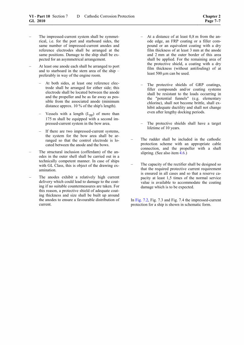
– The impressed-current system shall be symmet-rical, i.e. for the port and starboard sides, the same number of impressed-current anodes and reference electrodes shall be arranged at the same positions. Damage to the ship shall be ex-pected for an asymmetrical arrangement.
– At least one anode each shall be arranged to port and to starboard in the stern area of the ship – preferably in way of the engine room.
– At both sides, at least one reference elec-trode shall be arranged for either side; this electrode shall be located between the anode and the propeller and be as far away as pos-sible from the associated anode (minimum distance approx. 10 % of the ship's length).
– Vessels with a length (Lpp) of more than 175 m shall be equipped with a second im-pressed-current system in the bow area.
– If there are two impressed-current systems, the system for the bow area shall be ar-ranged so that the control electrode is lo-cated between the anode and the bows.
– The structural inclusion (cofferdam) of the an-odes in the outer shell shall be carried out in a technically competent manner. In case of ships with GL Class, this is object of the drawing ex-amination.
– The anodes exhibit a relatively high current delivery which could lead to damage to the coat-ing if no suitable countermeasures are taken. For this reason, a protective shield of adequate coat-ing thickness and size shall be built up around the anodes to ensure a favourable distribution of current.
– At a distance of at least 0,8 m from the an-ode edge, an FRP coating or a filler com-pound or an equivalent coating with a dry film thickness of at least 3 mm at the anode and 2 mm at the outer border of this area shall be applied. For the remaining area of the protective shield, a coating with a dry film thickness (without antifouling) of at least 500 μm can be used.
– The protective shields of GRP coatings, filler compounds and/or coating systems shall be resistant to the loads occurring in the "potential funnels" (e.g. elementary chlorine), shall not become brittle, shall ex-hibit adequate ductility and shall not change even after lengthy docking periods.
– The protective shields shall have a target lifetime of 10 years.
– The rudder shall be included in the cathodic protection scheme with an appropriate cable connection, and the propeller with a shaft slipring. (See also item 4.6.)
– The capacity of the rectifier shall be designed so that the required protective current requirement is ensured in all cases and so that a reserve ca-pacity at least 1,5 times of the normal service value is available to accommodate the coating damage which is to be expected.
In Fig. 7.2, Fig. 7.3 and Fig. 7.4 the impressed-current protection for a ship is shown in schematic form.
VI - Part 10 GL 2010
Section 7 Cathodic Corrosion Protection Chapter 2Page 7–7
D

�
�
�
������������ ����������
�� ������!"���������"��#���������$����%�
�� ������!"�������������&��������'����'���&(()*������������*
+��"����������������"�����
,�� ������"����"�����$������#����� ���%
-������"����"�����$���"����
Fig. 7.2 Schematic arrangement of an impressed-current system
-������"����"����
���#����� ���% +�����������������"�����
(()./�������
�����"���"� ����"��$��������
Fig. 7.3 Schematic arrangement of an impressed-current system (stern area)
Chapter 2 Page 7–8
Section 7 Cathodic Corrosion Protection VI - Part 10GL 2010
D

"�����������
-�"��#���
���� ����"��$� ��������
�0!�� ��
�����
0������
0������#��������
(������� ��������
+�!���������������"�����
/�!�����
�����"���"� ����"��$�������
��������&���"�������*
Fig. 7.4 Schematic circuit diagram for an im-pressed-current system
4. Monitoring and control
4.1 Impressed-current protection systems shall be fitted with voltage-controlling power supply units which may exhibit a slow control characteristic. It shall be possible to read the control electrodes indi-vidually, so that the protective current can be adjusted independent for port- and starboard side.
4.2 The possibility of switching over from auto-matic to manual operation shall be provided.
4.3 The following indicators shall be provided as a minimum: – Indicator light "On" – Indicator light "Manual Operation" – Common indicator light "Malfunction" – Indicator "Anode failure or anode group failure" – Measurement units for "Anode current", "Anode
voltage" and "Potential" (input impedance of the measurement circuit: ≥ 1 MΩ)
4.4 The target-value transmitter for setting the required potential shall be fitted with a locking ar-rangement.
4.5 Automatic limiters for anode current and anode voltage shall be provided.
4.6 In the event of wire break or short circuit at the control electrodes, the protective current shall be switched off automatically or regulated down to zero when in automatic mode.
4.7 For alerting purposes, each group alarm shall be routed via a potential-free contact (change-over) to the terminal strip of the power supply unit.
4.8 The control precision of the set voltage for the control electrodes (target value) shall be within ± 10 mV during automatic operation.
4.9 The measurement units shall be arranged so that it is easy to read off the measurement values regu-larly.
4.10 The potential values, the voltage difference at the shaft slipring and, if applicable, the anode current and anode voltage shall be recorded at regular inter-vals.
E. Maintenance of the Cathodic Protection System
During docking periods, the sacrificial anodes shall be checked for excessive metal loss, damage and for possible passivation, and also for uniformity of the metal loss. Furthermore, the mountings of the sacrifi-cial anodes shall be checked for proper electrical con-tact.
In the case of impressed-current systems, the condi-tion of the reference electrodes, the impressed-current anodes and the anodic protective shield shall be checked for damage.
During abrasive-blasting and high-pressure washing work at the outer shell, the reference electrodes, the impressed-current anodes and the anodic protective shields shall be protected against damage.
The voltage difference between the slipring of the propeller shaft and the brushes shall not exceed 40 mV, in order to prevent damage to the propeller bearings and the propeller shaft. Any instructions issued by the manufacturer shall be observed.
F. Documentation of the Cathodic Protection System
The installed cathodic corrosion protection system shall be described by appropriate documentation and can be presented to GL for examination. In the case of ships with GL Class that are to bear the Class Notation IW, the following documents shall be submitted, see GL Rules for Hull Structures (I-1-1), Section 35. The documentation shall, insofar applicable, cover the following points:
– Design data of the system (selected protective current densities and potential ranges for spe-cific areas for the ship, for each KSZ)
– Arrangement of the sacrificial anodes on the ship
– Specification of the sacrificial anodes, i.e. type or chemical composition, mass, capacity, manu-facturer, acceptance certificate
VI - Part 10 GL 2010
Section 7 Cathodic Corrosion Protection Chapter 2Page 7–9
F

– Type and arrangement of the reference elec-trodes and the impressed-current anodes as well as the rudder and propeller connections
– Type and design data of the rectifier
– Specification of the anodic protective shield
– Specification of the control unit
– Design of the cofferdams
Chapter 2 Page 7–10
Section 7 Cathodic Corrosion Protection VI - Part 10GL 2010
F

Section 8
Standards
A. Normative References
ISO 1461 Hot dip galvanized coatings on fabri-cated iron and steel articles - Speci-fications and test methods
ISO 8501 Preparation of steel substrates before application of paints and related pro-ducts - Visual assessment of surface cleanliness
ISO 11124 Preparation of steel substrates before application of paints and related prod-ucts - Specifications for metallic blast-cleaning abrasives
ISO 11126 Preparation of steel substrates before application of paints and related prod-ucts - Specifications for non-metallic blast-cleaning abrasives
ISO 12944 Paints and varnishes-Corrosion protec-tion of steel structures by protective paint systems
ISO 14918 Thermal spraying - Approval testing of thermal sprayers
ISO 14919 Thermal spraying - Wires, rods and cords for flame and arc spraying
EN 1395 Thermal spraying - Acceptance inspec-tion of thermal spraying equipment
EN 4618 Paints and varnishes - Terms and defini-tions
EN 12473 General principles of cathodic protec-tion in seawater
EN 12474 Cathodic protection for submarine pipe-lines
EN 12495 Cathodic protection for fixed steel off-shore structures
EN 13173 Cathodic protection for steel offshore floating structures
EN 13174 Cathodic protection for harbour installa-tions
EN 13507 Thermal spraying - Pre-treatment of surfaces of metallic parts and compo-nents for thermal spraying
EN 13509 Cathodic protection measurement tech-niques
EN 14879 Organic coating systems and linings for protection of industrial apparatus and
plants against corrosion caused by ag-gressive media
EN 22063 Metallic and other inorganic coatings - Thermal spraying - Zinc, aluminium and their alloys
VG 81255 Cathodic protection, materials for gal-vanic anodes
VG 81256 Cathodic protection of ships, external protection by galvanic anodes
VG 81258 Cathodic protection of ships, internal protection by galvanic anodes
VG 81259 Cathodic protection of ships, external protection by impressed current
DIN 50900 Corrosion of metals - Terms
DIN 50927 Planning and application of the electro-chemical corrosion protection... (inter-nal protection)
DIN 50929 Probability of corrosion of metallic materials when subject to corrosion from the outside
DIN 50930 Corrosion of metallic materials under corrosion load by water inside of tubes, tanks and apparatus
DIN 81249 Corrosion of metals in seawater and sea atmosphere
NORSOK Standard M-CR-503 – Cathodic protection
NORSOK Standard M-501 – Surface prepara-tion and protective coatings
IACS – Shipbuilding and Repair Quality Standard
SEW 390 – Non-magnetisable steels
SEW 395 – Non-magnetisable steel castings
B. Guidelines of the Society of Naval Archi-tects and Marine Engineers (STG)
STG 2215 Corrosion protection for ships and off-shore structures, Part 1 "...newbuildings"
STG 2216 STG-Data sheet for coating materials
VI - Part 10 GL 2010
Section 8 Standards Chapter 2Page 8–1
B

STG 2220 Testing and assessment of the suitability of coatings for immersed service for ships and offshore structures with ca-thodic protection systems
STG 2221 Corrosion protection for ships and off-shore structures, Part 1 "...maintenance"
STG 2222 Preparation grades for high-pressure water cleaning
C. DVS Merkblätter (Work Sheets)
DVS 2301 Guideline for thermal spraying of metal-lic and non-metallic materials
DVS 2304 Quality ensurance during thermal spray-ing
Chapter 2 Page 8–2
Section 8 Standards VI - Part 10GL 2010
C