Rules and Regs Pertaining to Extensions of Existing ...basapa.org/pdf/Microsoft Word - Rules and...
50
BUTLER AREA SEWER AUTHORITY BUTLER COUNTY, PENNSYLVANIA ________________________________________________________________________ RULES AND REGULATIONS PERTAINING TO EXTENSIONS OF EXISTING SANITARY SEWERS ________________________________________________________________________ DATED: APRIL 18, 1995 AS AMENDED: JANUARY 28, 2009 BUTLER AREA SEWER AUTHORITY 100 LITMAN ROAD BUTLER, PENNSYLVANIA 16001-3256 (724) 282-1978 www.basapa.org
Transcript of Rules and Regs Pertaining to Extensions of Existing ...basapa.org/pdf/Microsoft Word - Rules and...

BUTLER AREA SEWER AUTHORITY
BUTLER COUNTY, PENNSYLVANIA
________________________________________________________________________
RULES AND REGULATIONS
PERTAINING TO EXTENSIONS OF EXISTING
SANITARY SEWERS
________________________________________________________________________
DATED: APRIL 18, 1995
AS AMENDED: JANUARY 28, 2009
BUTLER AREA SEWER AUTHORITY
100 LITMAN ROAD
BUTLER, PENNSYLVANIA 16001-3256
(724) 282-1978
www.basapa.org
B.A.S.A. RULES AND REGULATIONS PERTAINING TO DATED: APRIL 18, 1995
EXTENSIONS OF EXISTING SANITARY SEWERS 2 AS AMENDED: JANUARY 28, 2009
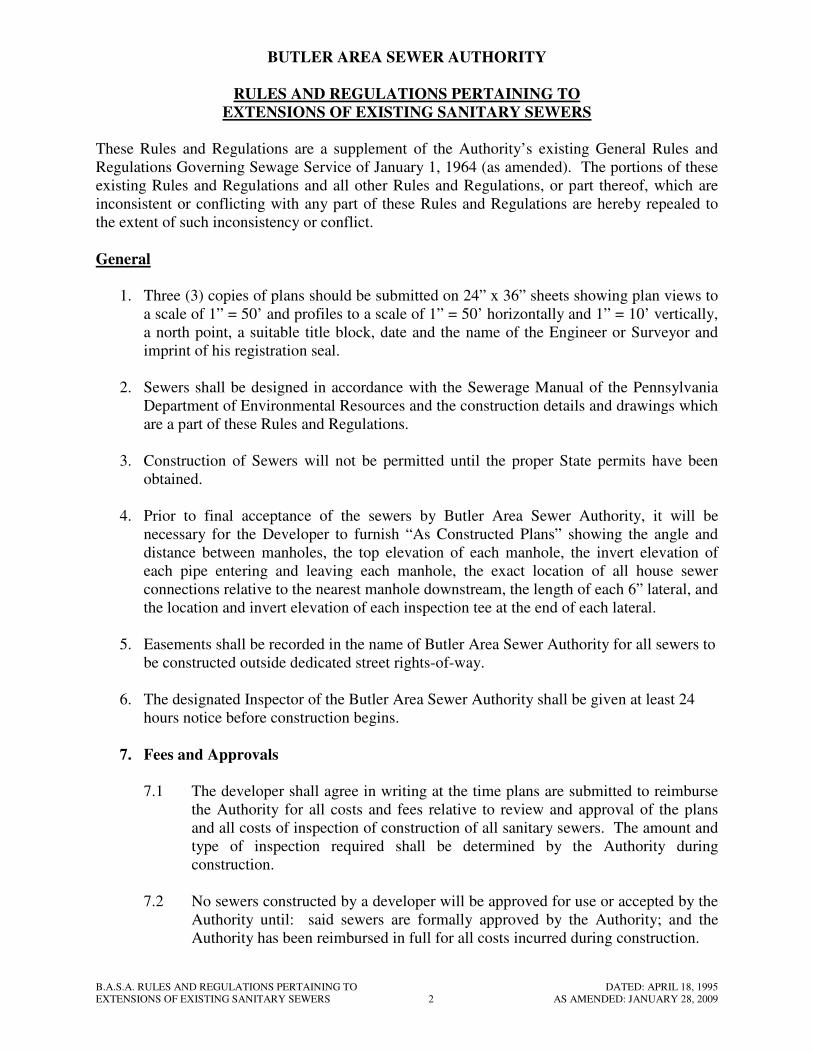
BUTLER AREA SEWER AUTHORITY
RULES AND REGULATIONS PERTAINING TO
EXTENSIONS OF EXISTING SANITARY SEWERS
These Rules and Regulations are a supplement of the Authority’s existing General Rules and
Regulations Governing Sewage Service of January 1, 1964 (as amended). The portions of these
existing Rules and Regulations and all other Rules and Regulations, or part thereof, which are
inconsistent or conflicting with any part of these Rules and Regulations are hereby repealed to
the extent of such inconsistency or conflict.
General
1. Three (3) copies of plans should be submitted on 24” x 36” sheets showing plan views to
a scale of 1” = 50’ and profiles to a scale of 1” = 50’ horizontally and 1” = 10’ vertically,
a north point, a suitable title block, date and the name of the Engineer or Surveyor and
imprint of his registration seal.
2. Sewers shall be designed in accordance with the Sewerage Manual of the Pennsylvania
Department of Environmental Resources and the construction details and drawings which
are a part of these Rules and Regulations.
3. Construction of Sewers will not be permitted until the proper State permits have been
obtained.
4. Prior to final acceptance of the sewers by Butler Area Sewer Authority, it will be
necessary for the Developer to furnish “As Constructed Plans” showing the angle and
distance between manholes, the top elevation of each manhole, the invert elevation of
each pipe entering and leaving each manhole, the exact location of all house sewer
connections relative to the nearest manhole downstream, the length of each 6” lateral, and
the location and invert elevation of each inspection tee at the end of each lateral.
5. Easements shall be recorded in the name of Butler Area Sewer Authority for all sewers to
be constructed outside dedicated street rights-of-way.
6. The designated Inspector of the Butler Area Sewer Authority shall be given at least 24
hours notice before construction begins.
7. Fees and Approvals
7.1 The developer shall agree in writing at the time plans are submitted to reimburse
the Authority for all costs and fees relative to review and approval of the plans
and all costs of inspection of construction of all sanitary sewers. The amount and
type of inspection required shall be determined by the Authority during
construction.
7.2 No sewers constructed by a developer will be approved for use or accepted by the
Authority until: said sewers are formally approved by the Authority; and the
Authority has been reimbursed in full for all costs incurred during construction.
B.A.S.A. RULES AND REGULATIONS PERTAINING TO DATED: APRIL 18, 1995
EXTENSIONS OF EXISTING SANITARY SEWERS 3 AS AMENDED: JANUARY 28, 2009
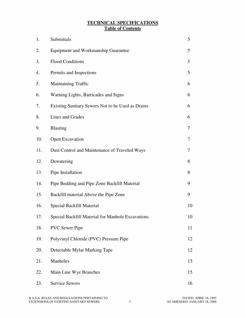
TECHNICAL SPECIFICATIONS
Table of Contents
1. Submittals 5
2. Equipment and Workmanship Guarantee 5
3. Flood Conditions 5
4. Permits and Inspections 5
5. Maintaining Traffic 6
6. Warning Lights, Barricades and Signs 6
7. Existing Sanitary Sewers Not to be Used as Drains 6
8. Lines and Grades 6
9. Blasting 7
10. Open Excavation 7
11. Dust Control and Maintenance of Traveled Ways 7
12. Dewatering 8
13. Pipe Installation 8
14. Pipe Bedding and Pipe Zone Backfill Material 9
15. Backfill material Above the Pipe Zone 9
16. Special Backfill Material 10
17. Special Backfill Material for Manhole Excavations 10
18. PVC Sewer Pipe 11
19. Polyvinyl Chloride (PVC) Pressure Pipe 12
20. Detectable Mylar Marking Tape 12
21. Manholes 13
22. Main Line Wye Branches 15
23. Service Sewers 16

B.A.S.A. RULES AND REGULATIONS PERTAINING TO DATED: APRIL 18, 1995
EXTENSIONS OF EXISTING SANITARY SEWERS 4 AS AMENDED: JANUARY 28, 2009
24. Concrete Work 16
25. Nonshrink Grout 17
26. Testing Sanitary Sewers 17
27. Pressure and Leakage Tests 19
28. Water Supply for Pressure Testing 20
29. [This Section Intentionally Left Blank] 20
30. Concrete Cradle and Encasement 20
31. Concrete Anchors 20
32. Grinder Pump Assemblies 21
33. Individual Grinder Pump Installation 24
34. Grinder Pump Pressure Sewer Systems 25
Standard Drawings 27
B.A.S.A. RULES AND REGULATIONS PERTAINING TO DATED: APRIL 18, 1995
EXTENSIONS OF EXISTING SANITARY SEWERS 5 AS AMENDED: JANUARY 28, 2009
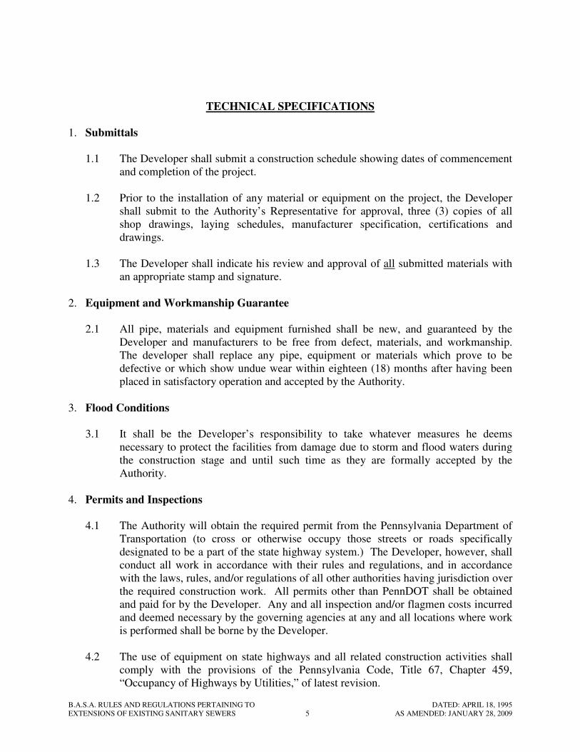
TECHNICAL SPECIFICATIONS
1. Submittals
1.1 The Developer shall submit a construction schedule showing dates of commencement
and completion of the project.
1.2 Prior to the installation of any material or equipment on the project, the Developer
shall submit to the Authority’s Representative for approval, three (3) copies of all
shop drawings, laying schedules, manufacturer specification, certifications and
drawings.
1.3 The Developer shall indicate his review and approval of all submitted materials with
an appropriate stamp and signature.
2. Equipment and Workmanship Guarantee
2.1 All pipe, materials and equipment furnished shall be new, and guaranteed by the
Developer and manufacturers to be free from defect, materials, and workmanship.
The developer shall replace any pipe, equipment or materials which prove to be
defective or which show undue wear within eighteen (18) months after having been
placed in satisfactory operation and accepted by the Authority.
3. Flood Conditions
3.1 It shall be the Developer’s responsibility to take whatever measures he deems
necessary to protect the facilities from damage due to storm and flood waters during
the construction stage and until such time as they are formally accepted by the
Authority.
4. Permits and Inspections
4.1 The Authority will obtain the required permit from the Pennsylvania Department of
Transportation (to cross or otherwise occupy those streets or roads specifically
designated to be a part of the state highway system.) The Developer, however, shall
conduct all work in accordance with their rules and regulations, and in accordance
with the laws, rules, and/or regulations of all other authorities having jurisdiction over
the required construction work. All permits other than PennDOT shall be obtained
and paid for by the Developer. Any and all inspection and/or flagmen costs incurred
and deemed necessary by the governing agencies at any and all locations where work
is performed shall be borne by the Developer.
4.2 The use of equipment on state highways and all related construction activities shall
comply with the provisions of the Pennsylvania Code, Title 67, Chapter 459,
“Occupancy of Highways by Utilities,” of latest revision.
B.A.S.A. RULES AND REGULATIONS PERTAINING TO DATED: APRIL 18, 1995
EXTENSIONS OF EXISTING SANITARY SEWERS 6 AS AMENDED: JANUARY 28, 2009
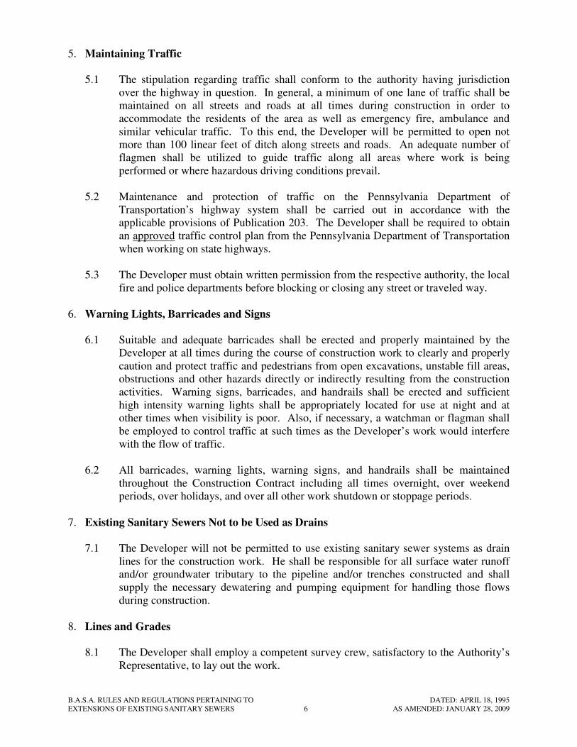
5. Maintaining Traffic
5.1 The stipulation regarding traffic shall conform to the authority having jurisdiction
over the highway in question. In general, a minimum of one lane of traffic shall be
maintained on all streets and roads at all times during construction in order to
accommodate the residents of the area as well as emergency fire, ambulance and
similar vehicular traffic. To this end, the Developer will be permitted to open not
more than 100 linear feet of ditch along streets and roads. An adequate number of
flagmen shall be utilized to guide traffic along all areas where work is being
performed or where hazardous driving conditions prevail.
5.2 Maintenance and protection of traffic on the Pennsylvania Department of
Transportation’s highway system shall be carried out in accordance with the
applicable provisions of Publication 203. The Developer shall be required to obtain
an approved traffic control plan from the Pennsylvania Department of Transportation
when working on state highways.
5.3 The Developer must obtain written permission from the respective authority, the local
fire and police departments before blocking or closing any street or traveled way.
6. Warning Lights, Barricades and Signs
6.1 Suitable and adequate barricades shall be erected and properly maintained by the
Developer at all times during the course of construction work to clearly and properly
caution and protect traffic and pedestrians from open excavations, unstable fill areas,
obstructions and other hazards directly or indirectly resulting from the construction
activities. Warning signs, barricades, and handrails shall be erected and sufficient
high intensity warning lights shall be appropriately located for use at night and at
other times when visibility is poor. Also, if necessary, a watchman or flagman shall
be employed to control traffic at such times as the Developer’s work would interfere
with the flow of traffic.
6.2 All barricades, warning lights, warning signs, and handrails shall be maintained
throughout the Construction Contract including all times overnight, over weekend
periods, over holidays, and over all other work shutdown or stoppage periods.
7. Existing Sanitary Sewers Not to be Used as Drains
7.1 The Developer will not be permitted to use existing sanitary sewer systems as drain
lines for the construction work. He shall be responsible for all surface water runoff
and/or groundwater tributary to the pipeline and/or trenches constructed and shall
supply the necessary dewatering and pumping equipment for handling those flows
during construction.
8. Lines and Grades
8.1 The Developer shall employ a competent survey crew, satisfactory to the Authority’s
Representative, to lay out the work.
B.A.S.A. RULES AND REGULATIONS PERTAINING TO DATED: APRIL 18, 1995
EXTENSIONS OF EXISTING SANITARY SEWERS 7 AS AMENDED: JANUARY 28, 2009
9. Blasting
9.1 All blasting shall be done by licensed blasters and the Developer shall conform to all
federal, state and local laws and regulations regarding transportation, storage and use
of explosives.
10. Open Excavation
10.1 The depth of trenches shall be such that the location of the proposed pipes will
conform with the lines and grades shown on the plans or as approved by the
Authority’s Representative in the field during construction. The shape of all trenches
above and within the pipe zone, the construction methods employed, the general
excavation requirements, the general trenching requirements, and the minimum
regulations for trench shoring, shall conform with the regulations set forth under
Subpart P, “Excavation, Trenching and Shoring” published as part of the Safety and
Health Regulations for Construction by the U.S. Department of Labor, as amended.
No trenching excavation work shall be performed which is not in accordance with
those regulations.
10.2 The shape of the trenches in the “pipe zone” (which shall be construed to be that
portion of the trench between the trench bottom and an elevation 1 ft. above the top of
the pipe), shall conform to the configuration identified as “Typical Bedding” on
Standard Drawing No. 1. The Developer is herein advised that if trench widths in the
pipe zone exceed the outside diameter of the pipe plus 2 ft., and if the Authority’s
Representative determines that such excessive widths will result in structural loadings
for which the pipe is not designed, he shall be required to bed the pipe on concrete
cradle as directed by the Authority’s Representative.
10.3 The bottom of all trenches shall be excavated to a depth of 0.5 ft. below the bottom of
the proposed lines to accommodate the bedding hereinafter specified.
10.4 The depth of trench for pipeline shall be such that pipe in its installed position, will
comply with the lines and grades shown on the plans, or as approved by the
Authority’s Representative in the field during construction. The minimum cover for
pipelines conveying liquid shall be 4 ft. unless otherwise indicated on the plans.
10.5 All open excavation in the construction area shall be adequately barricaded and
posted with battery operated warning lights, signs, etc., as required by any Local,
State or Federal regulations.
10.6 All inlets and discharge piping within the area of the manhole excavation shall be
properly supported or installed in concrete cradle and the cradle shall extend a
minimum of 3 ft. and as far into the pipe trench as necessary to protect the pipe to
where standard trench conditions are reached.
11. Dust Control and Maintenance of Traveled Ways
11.1 The Developer shall furnish and apply a commercial grade of calcium chloride,
(meeting the requirements of ASTM D-98), and/or water for laying dust caused from
B.A.S.A. RULES AND REGULATIONS PERTAINING TO DATED: APRIL 18, 1995
EXTENSIONS OF EXISTING SANITARY SEWERS 8 AS AMENDED: JANUARY 28, 2009
excavation or grading operations during construction. Method and rates of
application shall be approved by the Authority’s Representative. He shall also flush
streets and highways and mechanically, manually, or otherwise continually maintain
those traveled roadways where dust, mud, frozen material, debris, unstabilized fills,
stockpiles, or other results of construction of the project are hazardous to traffic both
during and after working hours throughout the construction.
11.2 Open trenches located along or across traveled ways shall be made safe for vehicular
traffic as soon as possible.
12. Dewatering
12.1 The Developer shall provide and maintain in operation suitable and adequate
pumping and/or well point equipment for completely dewatering any and all trench
excavations in such as manner as to permit the successful installation of the proposed
improvements.
12.2 The Developer shall take all necessary precautions to protect all construction against
flooding and/or floatation from hydrostatic uplift.
12.3 All water pumped or drained from the construction site shall be properly disposed of
by the Developer in accordance with all regulations and requirements of all governing
authorities, including erosion and sedimentation control activities. No storm or
surface water shall be disposed of in new or existing sanitary sewer facilities.
13. Pipe Installation
13.1 Before any pipe is installed in trenches, it shall be inspected for damage and the
inside of the pipe shall be swabbed to remove loose dirt and foreign objects. No
damaged pipe will be permitted to be installed.
13.2 All pipe shall be installed to the lines and grades shown on the drawings or as
approved by the Authority’s Representative in the field. No pipes shall be
constructed in trenches in which water flows or is pooled, and all pipes shall be
carefully handled in the ditch to keep the jointing ends and materials free from dirt
during installation. During shut down periods and at the end of each day, all open
ends of pipes shall be suitably plugged to prevent the inflow of water, dirt, foreign
objects, etc.
13.3 Sewers shall show, substantially, a full circle of light between manholes.
13.4 Each pipe manufacturer shall furnish a pipe installation manual for the Developer and
the Authority’s Representative for each different type of pipe supplied. Each pipe
manufacturer shall also furnish a representative to remain on the job site for a
sufficient period of time at the start of the job to instruct the Developer’s personnel
and to insure proper installation of the pipe.
13.5 Flexible couplings furnished under this Contract shall be non-shear, and designed to
resist uneven ground loading shear stress. Flexible couplings shall be fabricated of
elastomeric polyvinyl chloride (PVC). All clamps, including the band and housing,
B.A.S.A. RULES AND REGULATIONS PERTAINING TO DATED: APRIL 18, 1995
EXTENSIONS OF EXISTING SANITARY SEWERS 9 AS AMENDED: JANUARY 28, 2009
shall be stainless steel series 300. Couplings shall be designed to connect any two
pipes of dissimilar materials to form a positive seal against inflow and infiltration.
Couplings shall be Non-Shear Coupling as manufactured by DFW/HPI Plastics, Inc.,
or Authority approved equal.
14. Pipe Bedding and Pipe Zone Backfill Material
14.1 All proposed pipeline shall be supported on a crushed limestone material such as
(A.A.S.H.T.O.) No. 57, No. 67 stone, (see PennDOT Publication 408, Section
703.2(c), Table C) or similar angular graded material, not to exceed 1-1/2”, approved
by the Authority’s Representative. Smooth or rounded gravel will not be acceptable.
The material shall be placed to a minimum depth of 0.5 feet below the bottom of the
pipe and installed to the springline of the pipe for the full width of the trench. For all
types of pipe, said material shall further be required to be placed in the entire pipe
zone, defined as all that portion of the trench between the trench bottom and an
elevation one (1) foot above the top of the pipe in its installed position. The bedding
and backfill material shall then be choked as required by the Authority’s
Representative with approved material in sufficient quantities to prevent migrations
of the surrounding soils into the bedding and backfill. The material shall be placed in
the pipe zone in such a manner as to not disturb, displace, or otherwise misalign the
installed pipelines.
15. Backfill Material Above the Pipe Zone
15.1 In general, the material excavated during trenching and other construction operations
shall be used as backfill between the top of the pipe zone and the bottom of the
topsoil or other unimproved surface treatments. Said material shall be used for full
depth of trench to the finished ground surface where the ground is unimproved.
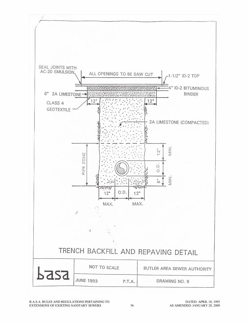
Where open cuts are located in state roads, streets, driveways, shoulders, alleys,
parking lots or under any paved cartway or improved surface area subject to vehicular
traffic, the material used above the pipe zone shall be PennDOT No. 2A crushed
limestone aggregate (see PennDOT Publication 408, Section 703.2(c) Table C) or
similar material as approved by the Authority’s Representative. The material shall be
used for the full depth of trench above the pipe zone to the bottom of the road, street,
driveway or shoulder subbase. The entire depth within the backfilled area shall be
compacted to provide the depth within the backfilled area shall be compacted to
provide the minimum percentage of density specified for each area of classification:
a. Percentage of maximum Density and Optimum Water Content Requirements:
Compact soil to not less than the following percentages of maximum dry density
for soils which exhibit a well-defined moisture density relationship, determined in
accordance with ASTM D 1557, and not less than the following percentages of
relative density, determined in accordance with ANSI/ASTM D2049, for soils
which will not exhibit a well-defined moisture-density relationship.
(1) Structures: Compact top 12 in. of subgrade and each layer of backfill or
fill at 95% maximum dry density at a moisture content that lies within
3% of the optimum moisture content or 80% relative density.
B.A.S.A. RULES AND REGULATIONS PERTAINING TO DATED: APRIL 18, 1995
EXTENSIONS OF EXISTING SANITARY SEWERS 10 AS AMENDED: JANUARY 28, 2009
(2) Building Slabs and Steps: Compact top 12 in. of subgrade and each
layer of backfill or fill material at 95% maximum dry density at a
moisture content that lies within 3% of the optimum moisture content or
80% relative density.
(3) Lawn or Unpaved Areas: Compact top 6 in. of subgrade and each
layer of backfill or fill material at 90% maximum dry density at a
moisture content that lies within 3% of the optimum moisture content.
(4) Walkways: Compact top 6 in. of subgrade and each layer of backfill or
fill material at 95% maximum dry density at a moisture content that lies
within 3% of the optimum moisture content or 80% relative density.
(5) Pavements: Compact top 12 in. of subgrade and each layer of backfill or
fill material at 95% maximum dry density at a moisture content that lies
within 3% of the optimum moisture content or 80% relative density for
cohesionless granular materials.
15.2 In the event that the Developer desires to employ the use of special vibratory and/or
heavy-duty machinery for that purpose, such methods will be approved by the
Authority’s Representative, subject to demonstration by the Developer that
satisfactory end results can be attained. Flooding of trenches will similarly be
considered. In any event, restoration of trench settlements occurring within eighteen
(18) months after completion of the work shall be the responsibility of the Developer
at no extra cost to the Authority. Particular care shall be exercised by the Developer
in backfilling trenches located along or crossing streets, street berms, roadways,
parking areas, and other traveled ways, such that the resumption of normal traffic
patterns will occur reasonably soon after the pipe in those areas has been installed.
16. Special Backfill Material
16.1 Where, because of local, county, state, or other regulations special backfill material is
required to be installed in unimproved cut areas, the Authority and/or his
Representative in the field will specify to the Developer the type of said special
backfill material and the same shall be obtained, placed, and thoroughly compacted
by the Developer.
16.2 Where muck, quicksand, soft clay, swampy or other material is encountered in the
trench bottom, which in the opinion of the Authority’s Representative, is unsuitable
for pipe foundation subgrade or backfill, such material shall be removed to a depth
satisfactory to the Authority’s Representative. The trench shall then be backfilled to
grade with acceptable Authority approved material, mechanically compacted in
successive layers.
17. Special Backfill Material for Manhole Excavations
17.1 For all new manholes installed in streets, roads, or other improved surface areas, the
entire excavated area around the new manhole shall be backfilled with crushed
limestone material such as A.A.S.H.T.O. No. 57 or No. 67 stone (see PennDOT,
publication 408, Section 703.2(c), Table C), or similar material approved by the
B.A.S.A. RULES AND REGULATIONS PERTAINING TO DATED: APRIL 18, 1995
EXTENSIONS OF EXISTING SANITARY SEWERS 11 AS AMENDED: JANUARY 28, 2009
Authority’s Representative. The backfill material shall be installed completely
around the manhole from its bottom base up to the bottom of the improved surface
area. The stone shall further be required to be placed in the inlet and outlet pipe
trench area of the manhole so that its surface forms an approximate 45 degree angle
with the top of the manhole.
17.2 For all new manholes installed in unimproved surface areas the entire excavated area
around the new manhole shall be backfilled with crushed limestone material such as
A.A.S.H.T.O. No. 57 or 67 stone (see PennDOT Publication 408, Section 703.2(c),
Table C) or similar material approved by the Authority’s Representative. The
backfill material shall be installed completely around the manhole from its bottom
base up to a point 12 in. above the top of the highest pipe entering the manhole.
18. PVC Sewer Pipe
18.1 Polyvinyl chloride (PVC) sewer pipe and fittings furnished under this Contract shall
conform to ASTM Specifications D-3034, of latest revision SDR 35 (with a cell
classification of 12454B). PVC sewer pipe shall be supplied in minimum 12.5 ft.
lengths except where connections to manholes or main line wye branches are to be
made in which case a shorter length will be permitted to be installed. Joints shall be
elastomeric gasket type.
18.2 Prior to delivery to the job site, the pipe manufacturer shall submit three (3) notarized
copies of certifications to the Authority’s Representative that the pipe has been
manufactured, inspected, and tested according to these specifications and meets all
requirements thereof and all pipe delivered shall be so marked. All PVC pipe
furnished shall be tested for stiffness and deflection. Not less than one length of pipe
out of each 200 lengths furnished, or less that two lengths of each size and strength of
pipe furnished, shall be tested. Three (3) notarized copies of all test reports shall also
be submitted to the Authority’s Representative.
18.3 PVC sewer pipe shall be transported, unloaded, handled, and installed in strict
accordance with the manufacturer’s recommendations by personnel experienced in
laying such pipe. The manufacturer shall furnish a representative to remain on the
job site for a sufficient period of time at the start of the job to instruct the Developer’s
personnel and to insure proper construction of the sewer lines.
18.4 After the PVC pipe has been installed for a period of at least sixty (60) days, the
trench backfilled and tamped to original ground, the pipe tested for water tightness,
the Contractor, at his own expense, may be required to perform a field test to
demonstrate that the PVC pipe has not deflected beyond five percent (5%) of the
diameter of the pipe. The test and results will be approved by the Authority’s
Representative.
18.5 An approved manhole coupling or flexible waterstop shall be installed around the
pipe when it enters and leaves each manhole, concrete encasement, concrete
waterstop or anchor, or concrete structure.
B.A.S.A. RULES AND REGULATIONS PERTAINING TO DATED: APRIL 18, 1995
EXTENSIONS OF EXISTING SANITARY SEWERS 12 AS AMENDED: JANUARY 28, 2009
19. Polyvinyl Chloride (PVC) Pressure Pipe (ASTM D-2241)
19.1 Polyvinyl chloride pipe (PVC) shall be designed, manufactured, and tested in strict
accordance with ASTM D-2241. Three (3) notarized copies of all test reports shall be
submitted to the Authority’s Representative. The pipe shall be designed for
installation in trenches with an average depth of 5 ft. and be pressure rated at 200 psi
minimum with minimum standard dimension ratio (SDR) of 21 for both barrel and
bell dimensions. Pipe greater than 20 ft. in length will not be accepted. Pipe shall
bear the National Sanitation Foundation seal of approval and will comply with the
requirements for Type 1, Grade 1, (PVC 1120) of ASTM D-1874. The joint shall be
the push-on type with a rubber o-ring gasket conforming to ASTM D-1869.
19.2 Prior to delivery to the job site, the pipe manufacturer shall submit three (3) notarized
copies of certification that the pipe has been manufactured, inspected, and tested
according to these Specifications and meets all requirements thereof and all pipe
delivered shall be so marked.
19.3 All pipe supplied shall be made by one manufacturer.
19.4 The weight of any fittings, valve, or various appurtenance required in the control,
operation, or maintenance of the system shall not be carried by the PVC pipe. The
valve, fitting, etc., must be supported by a concrete cradle.
19.5 All fittings for PVC pressure pipe shall conform in all respects to ANSI Specification
A21.10, “Cast Iron and Ductile Iron Fittings, 2 in. through 48 in. for water and Other
Liquids,” and shall be at least 250 psi pressure classification. Fittings with wall
thickness not conforming to ANSI A21.10 will not be permitted. Joints shall be push-
on or mechanical joint, rubber gasket type, in general accord with ANSI Specification
A21.11. Fittings shall be double cement lined and coated with a standard thickness
bituminous material.
19.6 PVC pressure pipe shall be transported, unloaded, handled, and installed in strict
accordance with the manufacture’s recommendations by personnel experienced in
laying such pipe. The manufacturer shall furnish a representative to remain on the
job site for a sufficient period of time at the start of the job, to instruct the
Developer’s personnel and to insure proper construction of the lines.
20. Detectable Mylar Marking Tape
20.1 A detectable mylar marking tape shall be installed over all nonmetallic pressure lines
by the Developer. It shall be inductively locatable and conductively traceable using
standard pipe and/or cable locating devices. Care will be taken to insure that the
buried marking tape is mylar encased aluminum foil. The detectable marking tape
will bear the words “CAUTION—FORCE MAIN BURIED BELOW”. The printing
will be under mylar so as to be readable through the clear mylar. Maximum spacing
between the continuous warning message shall be 16 in.-36 in. The tape will be a
highly visible color and will be minimum 3 in. in width. The detectable marking tape
will be buried 4 to 6 in. below finish grade or as close to grade as is practical for
optimum detectability. The tape should be placed into backfill and allowed to settle
into place in the backfill.

B.A.S.A. RULES AND REGULATIONS PERTAINING TO DATED: APRIL 18, 1995
EXTENSIONS OF EXISTING SANITARY SEWERS 13 AS AMENDED: JANUARY 28, 2009
21. Manholes
21.1 All manholes shall consist of either pre-cast concrete base section manholes or cast-
in-place concrete base section manholes.
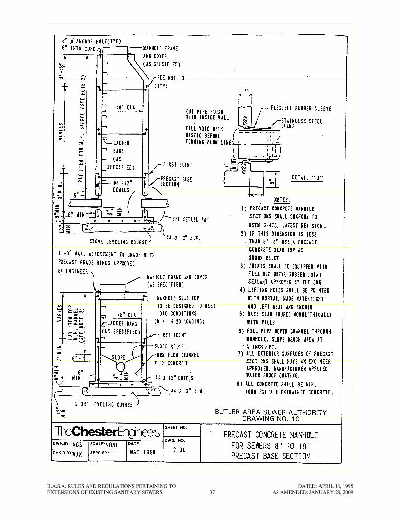
21.2 All pre-cast concrete base section manholes shall conform to the details shown on
Standard Drawing No. 10 (For Sewer 8 in. through 18 in.)
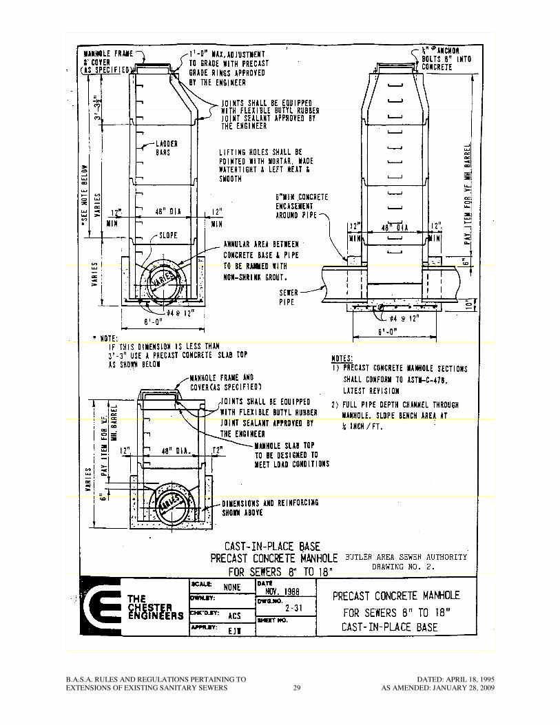
21.3 All cast-in-place concrete base section manholes shall conform to the details shown
on Standard Drawing No. 2 (For Sewers 8 in. through 18 in.).
Precast Concrete Base Sections:
21.4 The precast concrete base slab and precast concrete base riser sections shall be poured
monolithically with the base riser section having a minimum height of 2 ft. above the
top of the base and the base slab extending a minimum of 6 in. beyond the outside
diameter of the precast base riser section. The base slab section shall be installed on a
12 in. thick (minimum) subbase of (A.A.S.H.T.O.) No. 57 or No. 67 (see PennDOT
Publication 408, Section 703.2(c), Table C) compacted crushed stone. Prior to
installing the subbase stone, the excavated subbase area below the manhole shall be
thoroughly and evenly compacted.
21.5 An Authority approved flexible manhole sleeve shall be installed in the precast base
or riser section by the manhole manufacturer for a watertight installation. The
flexible watertight sleeve shall be a set a minimum of 4 in. above the manhole floor.
The influent and effluent flexible sleeves shall be set at elevations which will
maintain a minimum uniform grade through the manhole equal to the grade of the
sewers upstream or downstream of the respective manholes. Manholes shall not be
ordered by the Developer from the manufacturer, until complete field layout of the
proposed pipe line is established, staked, and approved by the Authority’s
Representative. This field layout will establish the proper horizontal and vertical
alignments on influent and effluent lines of the manholes. No manholes shall be
delivered to the site unless and until receipt by the Authority’s Representative of
notarized certification that the manhole base slab is monolithically poured with the
vertical base riser section, that the required and specified air entrained concrete is
being used, and that all manhole sections and materials meet the appropriate
specifications.
21.6 All manholes shall be installed in accordance with the details outlined herein and as
may be directed in the field by the Authority’s Representative. All manholes are
subject to final field acceptance by the Authority’s Representative.
Cast-in-Place Concrete Base Sections:
21.7 The cast-in-place concrete base sections shall be as detailed on the respective
drawings including base reinforcement.
21.8 Joints at the bottom of the pre-cast manhole barrel where connection is made with the
pre-cast or cast-in-place concrete base shall be made to produce a watertight

B.A.S.A. RULES AND REGULATIONS PERTAINING TO DATED: APRIL 18, 1995
EXTENSIONS OF EXISTING SANITARY SEWERS 14 AS AMENDED: JANUARY 28, 2009
installation. The joints in the precast concrete manhole barrels (and between all
precast concrete grade rings) shall be filled with two (2) complete rings of a 1 in.
diameter approved flexible butyl rubber manhole joint sealant.
21.9 All manholes shall have poured-in-place inverts. No pre-cast or pre-poured inverts
will be permitted.
21.10 The Developer shall carefully form all full pipe depth channels and bench areas in
manhole bottoms such that the least amount of turbulence will be caused in the
sewage flow. All channels shall be steel trowel finished.
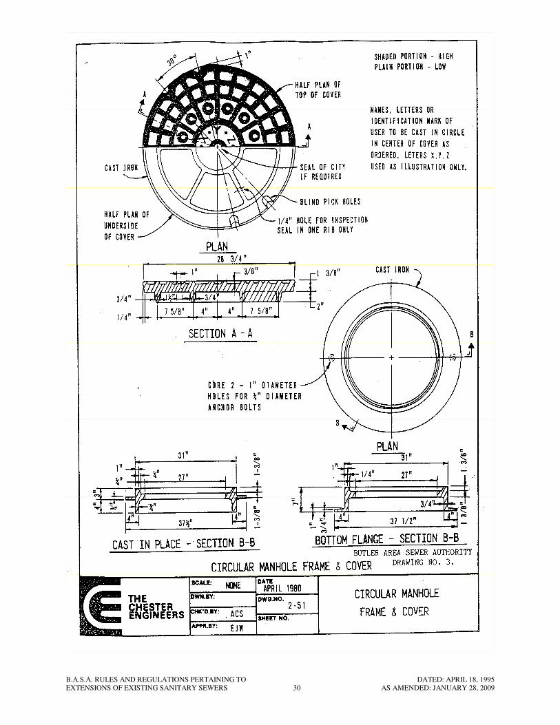
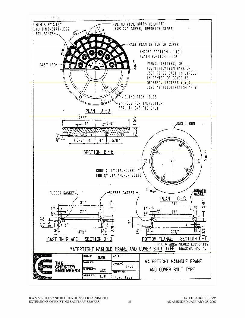
21.11 Frames and covers for all standard manholes shall be fabricated of cast iron and be of
uniform quality, free from blowholes, porosity, hard spots, blisters, shrinkage
distortion or other defects. They shall be smooth and well cleaned by shotblasting.
Materials used in the manufacture of castings shall conform to ASTM A48 of latest
revision, Class 30 or better. All castings shall be manufactured true to pattern and
component parts shall fit together in satisfactory manner. All frames and covers shall
have machined bearing surfaces to prevent rocking and rattling. All frames and
covers shall receive a factory painting of a manufacturer recommended black
asphaltum or bitumastic coating which shall be smooth and durable with no tendency
to scale or chip off. The standard manhole frame and cover shall conform to the
details as shown on Standard Drawing No. 3 for a minimum 27 in. frame size. The
final setting of manhole castings shall be such that they conform with the existing
ground slopes and/or final design elevations and shall be set to exclude surface water.
Where manholes are located along creeks or low areas subject to flooding and in
areas where they are subject to being covered, the top elevation shall be set above-
ground and landscaped as indicated on the contract drawings and/or as directed by the
Authority’s Representative. On each manhole two (2) complete rings of a 1/2 in.
diameter approved flexible butyl rubber joint sealant shall be installed between the
bottom of the frame and the top of the concrete of the manhole. Two 3/4 in. anchor
bolts shall be provided for all frames. All outer covers shall be furnished with the
lettering “Sanitary Sewer”.
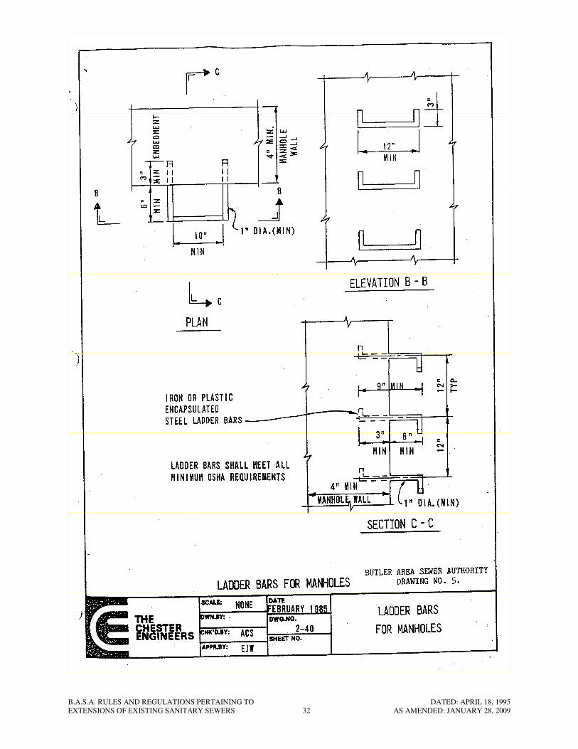
21.12 Ladder bars, furnished for manholes and concrete chambers, shall be designed in
accordance with the latest requirements of ASTM C-478 and shall generally conform
to the configuration and dimensions indicated on Standard Drawing No. 5. Ladder
bars to be embedded in cast-in-place concrete structures shall be cast in place at the
time of pour.
21.13 Ladder bars shall be fabricated of gray iron construction (minimum tensile strength
40,000 psi) or as alternate a minimum 3/8 in. round (minimum) steel step
encapsulated with copolymer polypropylene plastics. The steps shall be capable of
withstanding the design loading required in ASTM C-478 specifications at a
temperature of 0 deg. F with no structural failure.
21.14 An approved manhole coupling or flexible waterstop shall be installed around all pipe
where it enters and leaves each manhole.
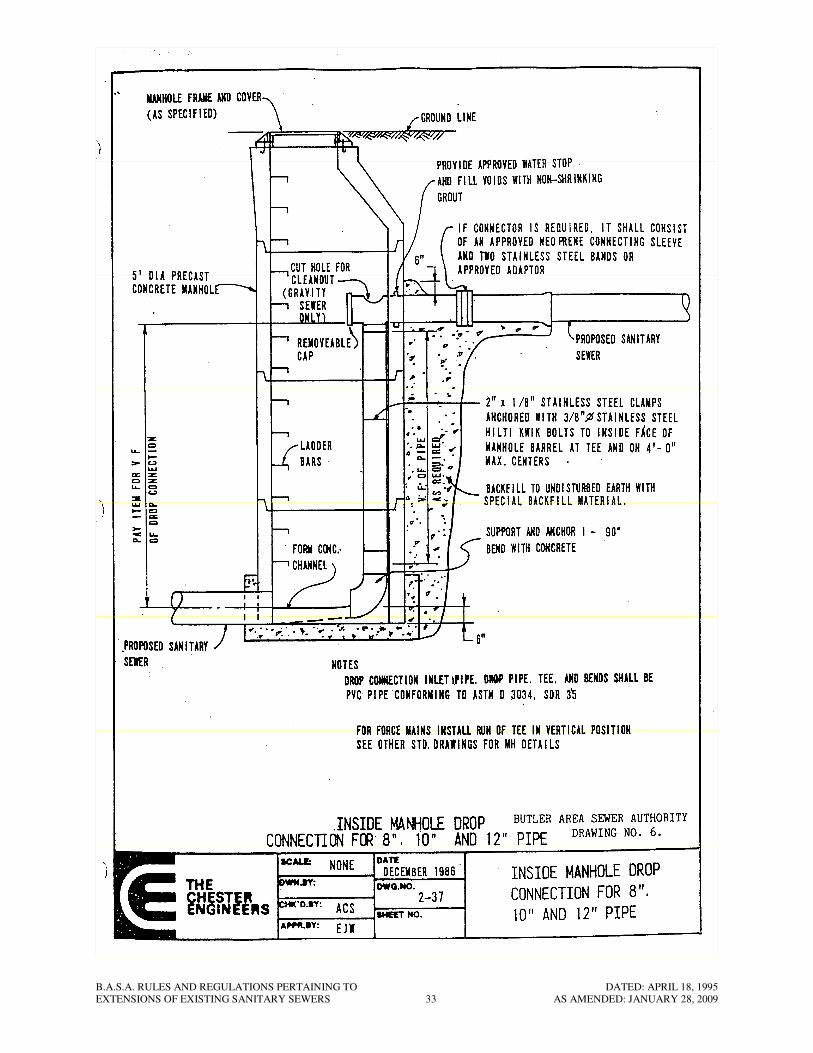
21.15 Wherever sewers enter manholes such that the influent inverts are in excess of 2 ft.
above the main invert of the manhole, drop connections shall be constructed in
B.A.S.A. RULES AND REGULATIONS PERTAINING TO DATED: APRIL 18, 1995
EXTENSIONS OF EXISTING SANITARY SEWERS 15 AS AMENDED: JANUARY 28, 2009
conformance with the details on Standard Drawings No. 6. Wherever sewers enter
manholes such that the influent invert of the sewer is above, but less than 2 ft. above,
the manhole bottom, a channeled concrete fillet shall be constructed to prevent the
flow from splashing into the manhole. The channeled concrete fillet shall be steel
trowel finished. All manhole flow channels shall be steel trowel finished.
21.16 Manhole eccentric cone sections, precast base sections, flat top sections, and barrel
sections shall not have more than two lifting holes per section for handling and
installation purposes. After installation, the holes shall be sealed (both inside and
outside) and made completely watertight. All sections shall also receive a factory
applied waterproof coating on all exterior surfaces. Materials shall be as
recommended by the manhole manufacturer. Developer shall provide final touch-up
coating to maintain complete integrity or repair damaged coated areas.
21.17 All of the above manhole sections shall be handled according to the manufacturer’s
recommendations so as to avoid chipping, cracking, or breaking. Any section
damaged in transporting, handling, or installation shall be replaced.
21.18 Each manhole section supplied shall be plainly marked on the inside of the manhole
section to indicate the date of manufacture and the name and/or trademark of the
manufacturer.
21.19 Prior to delivery to the jobsite, the manufacturer shall submit to the Authority’s
Representative three (3) notarized copies of certifications that all manholes sections
and materials were manufactured, inspected and tested in accordance with these
specifications and meet all of the requirements hereof.
21.20 Prior to delivery to the jobsite, shop drawing details of all manhole appurtenances
shall be submitted to the Authority’s Representative for approval including frame and
cover, steps, joint sealant, barrel and eccentric cone sections, and precast base
sections.
21.21 All concrete utilized for manholes (precast and cast-in-place) shall be in conformance
with the concrete section of these specifications, including air entrainment
requirements.
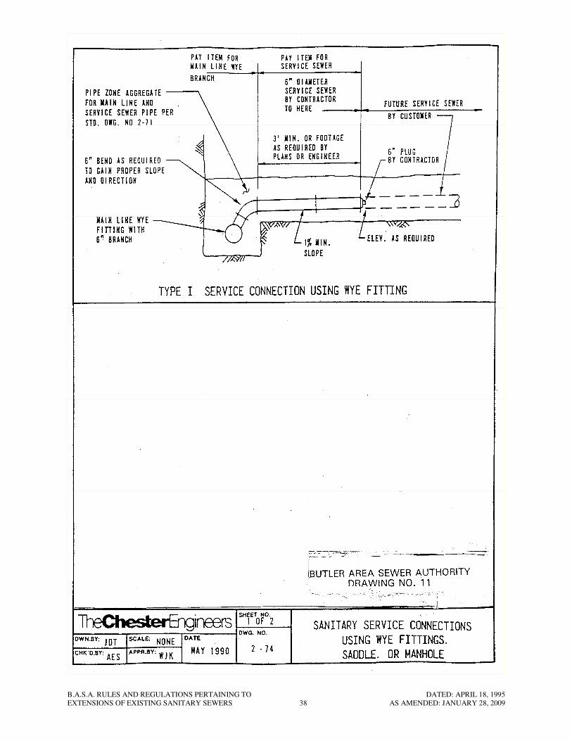
22. Main Line Wye Branches
22.1 Main line wye branches shall be the prefabricated wye branch type with a 6 in.
diameter branch size. Connection fitting shall be utilized as shown on Standard
Drawing No. 11. Other construction details shall conform with those shown on that
drawing.
22.2 All main line wye branches shall be installed so as to direct the flow from the service
sewer downstream. The angle between the upstream main line and the service sewer
shall not be greater than sixty (60) degrees, and in no case will ninety (90) degrees
main line wye branch tee connections be permitted.
B.A.S.A. RULES AND REGULATIONS PERTAINING TO DATED: APRIL 18, 1995
EXTENSIONS OF EXISTING SANITARY SEWERS 16 AS AMENDED: JANUARY 28, 2009
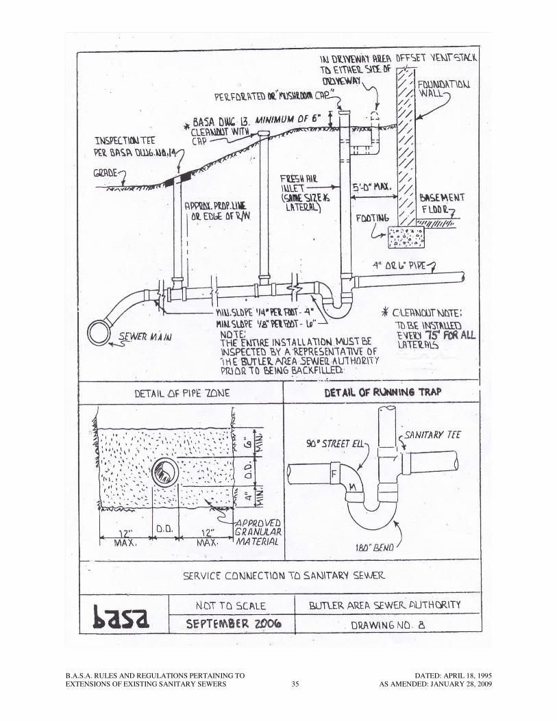
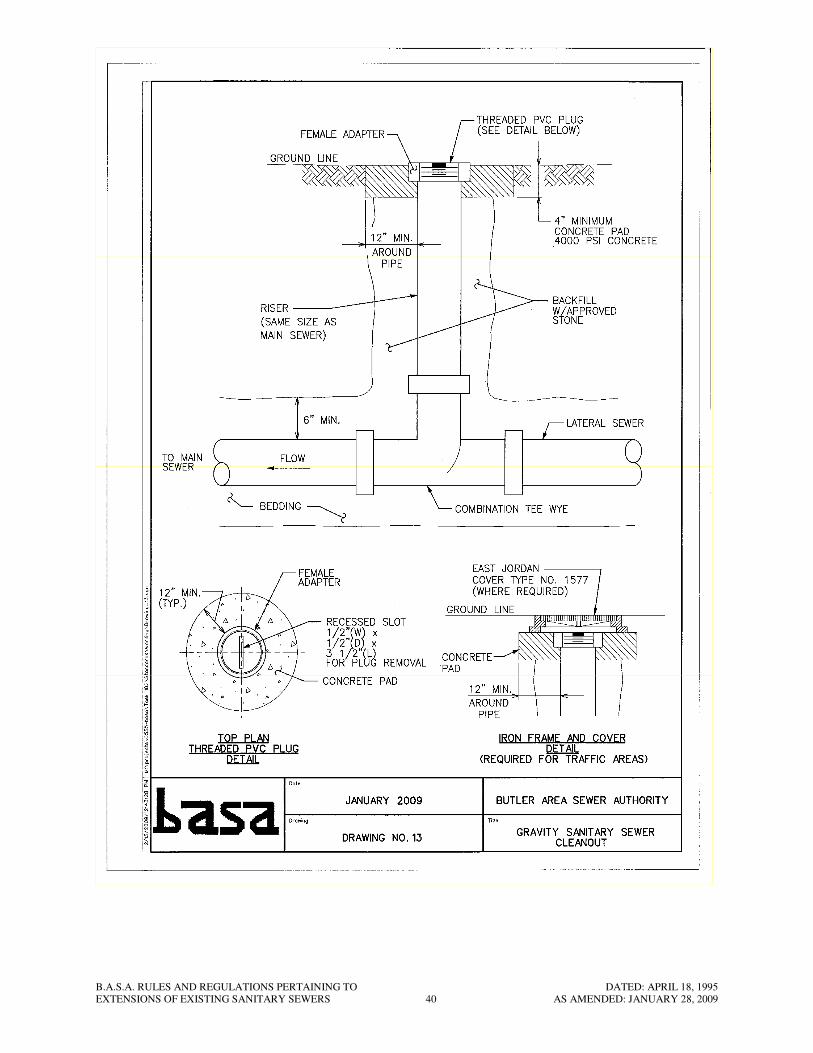
23. Service Sewers
23.1 All service sewers shall be 6 in. diameter pipe.
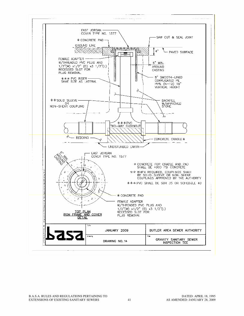
23.2 All 6 in. diameter service sewers shall be laid to a uniform grade no less than 1/8 in.
per ft. and to a straight line. The service sewer shall be terminated with an inspection
tee constructed in conformance with the details on Standard Drawings No. 14
23.3 The service sewers shall be 6 in. diameter pipe and of the same material as the main
line sewer. Class of pipe shall be:
PVC – SDR 35 ASTM D-3034
23.4 The Developer shall furnish to the Authority a separate “Wye Sheet” for each service
line or lot (see enclosed Drawing No. 12). Each Wye Sheet shall include all the
information as specified on the drawing, as well as a sketch showing the installation
and reference measurements as outlined on the SAMPLE. Blank forms of the Wye
Sheet will be supplied by the Authority prior to the start of construction.
24. Concrete Work
24.1 The Developer shall furnish all material, equipment, labor, and services to completely
install all of the concrete work as hereinafter specified and as indicated on the
drawings.
24.2 All concrete, grout and all ingredients thereof, including water, shall be subject to the
approval of the Authority’s Representative. The Developer shall notify the
Authority’s Representative at least 24 hours in advance of each concrete pour and no
concrete shall be poured until the excavations and reinforcement have been approved
by the Authority’s Representative. No concrete shall be deposited upon frozen, loose,
or otherwise unstable ground. All concrete to be used in this work shall be ready-mix
concrete conforming to the requirements of ASTM-C94 (latest revision.
24.3 The component materials of the concrete shall meet the following requirements;
a. Cement – Portland cement shall conform to the Standard Specifications for
Portland Cement of the American Society for Testing Materials, Serial
Designation C-150, Type II.
b. Aggregates – Concrete aggregates shall conform to the “Tentative Specifications
for Concrete Aggregate” ASTM Designation C33 except 10b and 10c will not
apply.
24.4 The minimum allowable compressive strength on samples taken from the
transportation unit at the point of discharge shall be 4,000 psi in 28 days. The
maximum allowable slump shall be 4 in. and the coarse aggregate shall be ASTM No.
467 or 57 (ASTM C33). The concrete mix shall be proportioned in accordance with
ANSI/ACI Standard No. 304 and ASTM Specification C94, Paragraph 4, Alternate
No. 2.
B.A.S.A. RULES AND REGULATIONS PERTAINING TO DATED: APRIL 18, 1995
EXTENSIONS OF EXISTING SANITARY SEWERS 17 AS AMENDED: JANUARY 28, 2009
24.5 Placing of concrete shall be done in accordance with ACI Standard 304, of latest
revision, Recommended Practice for Measuring, Mixing, and Placing Concrete,
Sections V and VI, and all applicable portions of said standards shall apply. No
concrete shall be poured in spaces where debris, oil, or water are present. Approval
of forms and reinforcement by the Authority’s Representative shall be obtained
before the concrete is placed. All concrete use in manhole bottoms, pavement
replacement, pipe cradle or encasement and for similar purposes shall b thoroughly
vibrated with approved mechanical vibrating equipment.
24.6 The Developer shall take all necessary precautions to insure that concrete placed
during hot or cold weather is not damaged by the extremities of temperature. To this
end, he shall place the concrete in accordance with the applicable portions of ACI
Standards 305 and 306. No concrete will be accepted which is frozen or damaged
due to extremes in weather.
24.7 The Developer shall make provision for the installation and casting into the concrete
of all sleeves, hatchway or grating frames, pipe, sewers, or other appurtenances
indicated on the drawing or described herein.
24.8 An air-entraining admixture shall be added to all concrete. (Precast and poured-in-
place). Admixture shall be added to the concrete to produce a 5% air content. Air
content shall not vary more than 1% from the specified amount. All admixtures shall
be added to the concrete in strict accordance with the recommendation of the
manufacturer.
25. Nonshrink Grout
25.1 All grout utilized shall be durable, nonstaining, nonshrink, nonmetallic grout. The
grout shall show no shrinkage in accordance with ASTM C-827 prior to initial setting
and shall show no shrinkage in the hardened state under ASTM C-157, Corps of
Engineers Specification CRD-C 588 and the field cylinder test. The grout shall
conform to ASTM C-191 concerning time of initial set. All grouting operations shall
be completed in accordance with the recommendations of ACI, CSI, and the
manufacturer’s published specifications for mixing and placing.
25.2 All grout utilized shall be “Five Star Grouts” as manufactured by U.S. Grout
Corporation, Greenwich, Connecticut; “Masterflow 713 Grout” as manufactured by
Master Builders, Cleveland, Ohio; or equal. Where nonmetallic grout is nonessential,
grout shall be a nonshrink, noncatalyzed, metallic grout such as Embecco 636 Grout,
as manufactured by Master Builders, Cleveland, Ohio or equal.
26. Testing Sanitary Sewers
Special Notice Regarding Testing
26.1 The Developer is hereby informed that construction of sewers beyond an initial 1,000
ft. of pipe will not be permitted until satisfactory test results are obtained.
26.2 Should the Developer desire to test before completion of service connections, he may
do so, but will be required to retest the same line with the completed service
B.A.S.A. RULES AND REGULATIONS PERTAINING TO DATED: APRIL 18, 1995
EXTENSIONS OF EXISTING SANITARY SEWERS 18 AS AMENDED: JANUARY 28, 2009
connections before final acceptance by the Authority. Subject to unsatisfactory initial
test results and at the Authority’s option, testing at 1,000 ft. maximum increments be
required throughout the project.
26.3 Each section of sewer between manholes, or for longer distances if the Authority’s
Representative shall so direct, shall be cleaned, tested and inspected. All repairs
shown to be necessary by the tests are to be made promptly. Broken or cracked pipe
shall be replaced and all deposits removed and the sewer left true to line and grade
and entirely clean. Each length of sewer is to show a full circle of light from manhole
to manhole.
26.4 All sewers shall be tested for leakage and any section of sewer showing leakage in
excess of the amount hereinafter set forth shall be rejected.
26.5 The air test shall be conducted by the Developer under the supervision of the
Authority’s Representative and shall be performed with AIR-LOC equipment
manufactured by Cherne Industrial, Inc., Hopkins, MN or approved equal.
26.6 The Developer may desire to perform an air test for his own purposes prior to
backfilling; however, the “acceptable air test” shall be performed after backfilling has
been completed.
26.7 Each section of sewer being tested shall be temporarily sealed off by means of
suitable plugs. In addition, all wyes, tees, or ends of lateral stubs shall be sealed with
suitable removable caps securely fastened to withstand internal test pressures.
26.8 The procedure and criteria to be used for air testing shall conform to that described by
the manufacturer of the respective pipe used and shall be in general conformance with
ASTM C-828.
26.9 All gauge pressures in the test shall be increased by the amount of groundwater
pressure at the crown of the pipe.
26.10 It is essential that the plugs be properly secured and care be exercised in their
removal. All plugs shall be blocked and carefully braced to prevent sudden release of
compressed air, slippage, or blowout due to internal pressure.
26.11 To protect against injury due to the above-mentioned hazards, no one shall be
permitted in the manhole or at the end of the pipe test section during testing.
26.12 The pressurizing equipment shall have a safety gauge which shall limit the loading on
the sewer line to 10 psi. In addition, the calibrations on all pressure gauges shall be
no greater than 0.10 psi.
26.13 If the pipe installation fails to meet these requirements, the Developer shall determine
the source of sources of leakage, and he shall repair or replace all defective materials
and workmanship including re-backfilling, compaction, and all surface restoration.
26.14 Immediately following the testing, an amount of not less than 500 gallons of fresh
water shall be flushed through the system from the upstream end of each separate
B.A.S.A. RULES AND REGULATIONS PERTAINING TO DATED: APRIL 18, 1995
EXTENSIONS OF EXISTING SANITARY SEWERS 19 AS AMENDED: JANUARY 28, 2009
branch. After the fresh water has flowed through, the newly constructed pipe shall be
internally inspected by the developer using closed-circuit television equipment. A
color 1/2” VHS video tape shall be supplied to the Authority, and shall be complete
with audio description, on-screen titling showing manhole numbers, direction of flow,
size and type of pipe, date of the inspection, and on-screen footage display accurate to
tenths of one foot. In the event any defects are found, they shall be properly repaired
by the developer, regardless of the outcome of the air pressure testing done
previously. The video tape shall become the property of the Authority. Under no
circumstances shall infiltration in any section of pipe between two adjacent manholes
exceed 50 gal/mile/in.-diameter/day.
27. Pressure and Leakage Tests
27.1 All pressure pipelines shall be tested by the Developer in a manner satisfactory to and
witnessed by the Authority’s Representative. The Developer shall furnish all
equipment, apparatus, temporary blocking, pumps, taps and gages to conduct the
following tests:
a. The section under test shall be filled with water and all air expelled from the line
and maintained full of water for a period of not less than 24 hours.
b. The pressure and leakage tests shall be conducted concurrently, and consist of
raising the water pressure (based on the elevation of the lowest point of the
section under test and corrected to the gage elevation) to a pressure in pounds per
square inch numerically equal to 1.5 times the normal working pressure or, 50 lb.
greater than the normal working pressure of the pipe, whichever is greater, and
maintaining such pressure for a period of 2 hours.
c. For all piping at the end of the test period, the section test will be accepted if the
total leakage is not greater than 10 gals/inch-dia./mile/24 hrs. Leakage shall be
defined as the quantity of water that must be supplied into the newly laid pipe, or
any valve section thereof, to maintain pressure within 5 psi of the specified test
pressure after the pipe has been filled with water and the air in the pipeline has
been expelled.
d. If the section fails to pass the pressure and leakage tests, the Developer shall do
everything necessary to locate, uncover and repair or replace the defective pipe,
fittings or joints. Additional test and repairs shall be made until the section passes
the specified test.
e. All visible leaks are to be repaired regardless of whether or not the pipe meets the
test requirements.
f. All testing shall be made from valve to valve (maximum) throughout the system
to insure the proper operation of each valve.
27.2 Manholes shall be tested separately and independently from sewer lines. Leakage
tests at manholes shall be made by the Contractor and observed by the Authority
Representative periodically during construction. The test shall be a manhole vacuum
test as described herein. Testing shall be in accordance with ASTM C 1244, of the
B.A.S.A. RULES AND REGULATIONS PERTAINING TO DATED: APRIL 18, 1995
EXTENSIONS OF EXISTING SANITARY SEWERS 20 AS AMENDED: JANUARY 28, 2009
latest edition, “Standard Test Method for Concrete Sewer Manholes by Negative Air
Pressure (Vacuum) Test”.
a. All lifting holes and exterior joints shall be filled and pointed with an approved
non-shrinking mortar grout.
b. Manholes are to be tested immediately after assembly and after backfilling. No
standing water shall be allowed in the manhole excavation which may affect the
accuracy of the test.
c. All incoming and outgoing piping shall be plugged through the use of suitably
sized pneumatic plugs in such a manner as to prevent displacement of the plugs
while the vacuum is on.
d. The vacuum head tester assembly shall be installed on the top of the secured
frame so that the frame-cone joint is also tested. The manhole tester head
assembly shall be circular in shape, properly sized to accommodate the manhole
opening diameter.
e. The testing shall be accomplished by starting the vacuum pump engine and
stabilizing the rpm’s. The manhole shall then be tested to 10 inches mercury
vacuum. The maximum allowable drop will be 1 inch mercury during 60
seconds.
f. If the manhole fails the test, necessary repairs shall be made by the Contractor by
a method and in a manner approved by the Authority, and the vacuum test
repeated until the manhole passes the test.
g. If the manhole joint mastic is displaced during the vacuum test, the manhole shall
be disassembled, the seal replaced, and the manhole retested.
28. Water Supply for Pressure Testing
28.1 The Developer shall be responsible for providing the quantity and quality of water
necessary for proper pressure testing of pipe and/or manholes.
28.2 Water supply for gravity sanitary sewer lines, force mains, or other non-potable water
lines, shall be free of sand, mud solids, oil, acids, and any other deleterious materials.
29. [This Section Intentionally Left Blank]
30. Concrete Cradle and Encasement
30.1 Concrete Cradle and Encasement, if required, shall be furnished and installed in
accordance with Drawing No. 1.
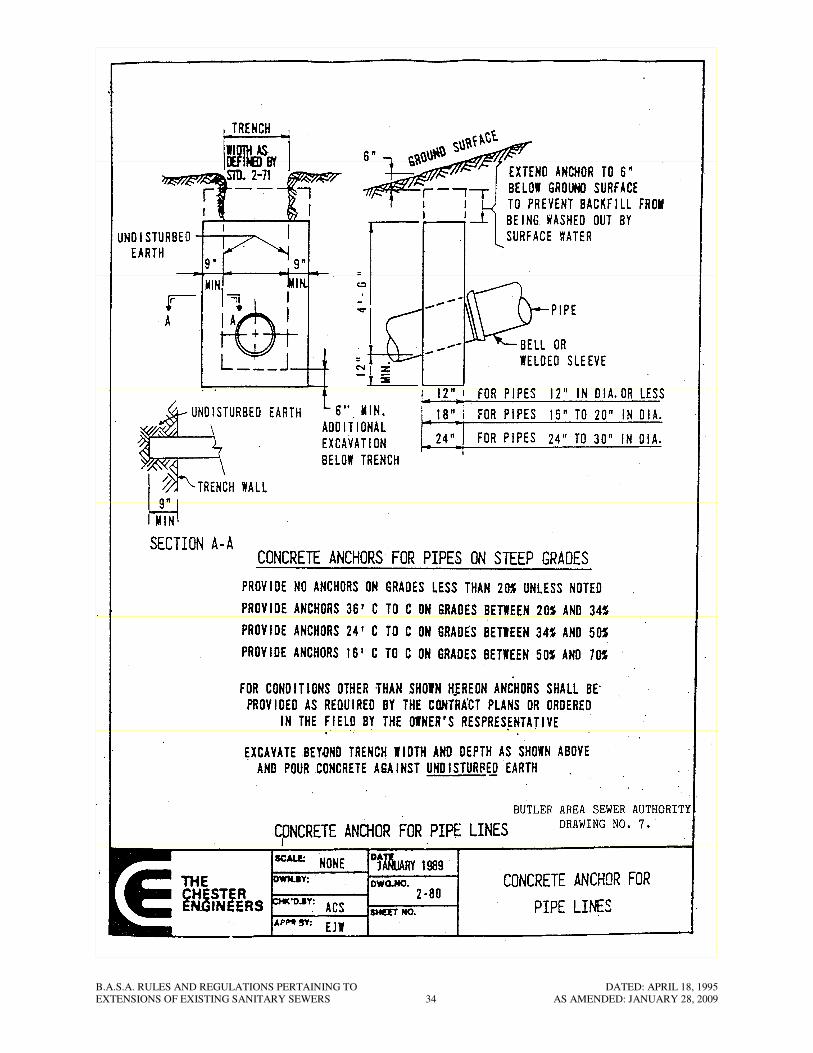
31. Concrete Anchors
31.1 Concrete Anchors, if required, shall be installed in accordance with Drawing No. 7.

B.A.S.A. RULES AND REGULATIONS PERTAINING TO DATED: APRIL 18, 1995
EXTENSIONS OF EXISTING SANITARY SEWERS 21 AS AMENDED: JANUARY 28, 2009
32. Grinder Pump Assemblies
32.1 General
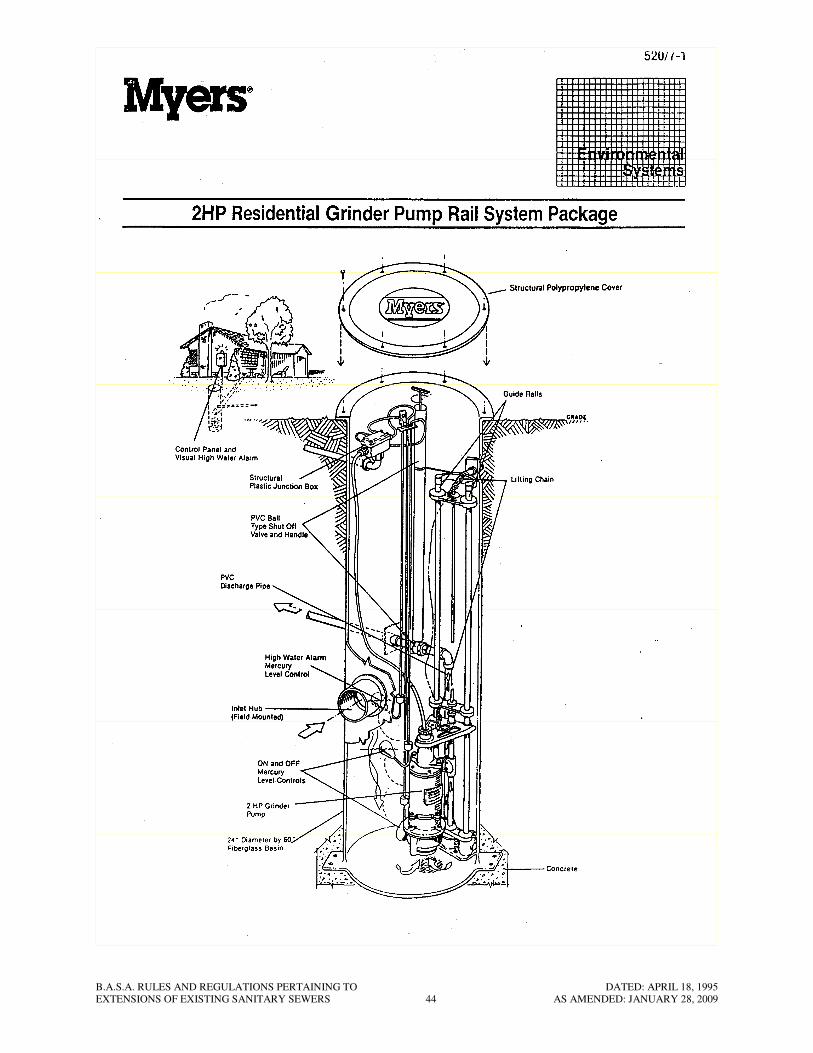
a. The grinder pump assemblies shall be Model WGL-20-21, a product of F.E.
Myers Company, Ashland, OH, as per Myers Specifications 520 pages 7-1
through 7-11 attached hereto subject to the following additions and/or
Modifications.
b. Contractor shall furnish and install a 6 in. leveling course of AASHTO No. 57
stone for each basin.
c. Contractor shall furnish and install a 12 in. thick precast reinforced concrete pad
for each basin and shall anchor each basin to the concrete pad.
d. Contractor shall backfill each basin excavation with clean sand to a depth of 12
in. below finished grade. The remaining excavation shall be backfilled with clean
topsoil.
e. Basin size shall be 24 in. diameter minimum with an overall depth of 8 ft.
f. The basins shall be certified by the manufacturer as structurally sound for the
intended service. Any basin whose walls have cracked, buckled or otherwise
shown any sign of damage or disfiguration at any time after backfilling operations
have been completed and within the specified warranty period shall immediately
be replaced with a completely new base assembly.
g. The basin shall be anchored to the precast reinforced concrete pad using 3/4 in.
diameter stainless steel bolts.
32.2 Basin Piping and Valves
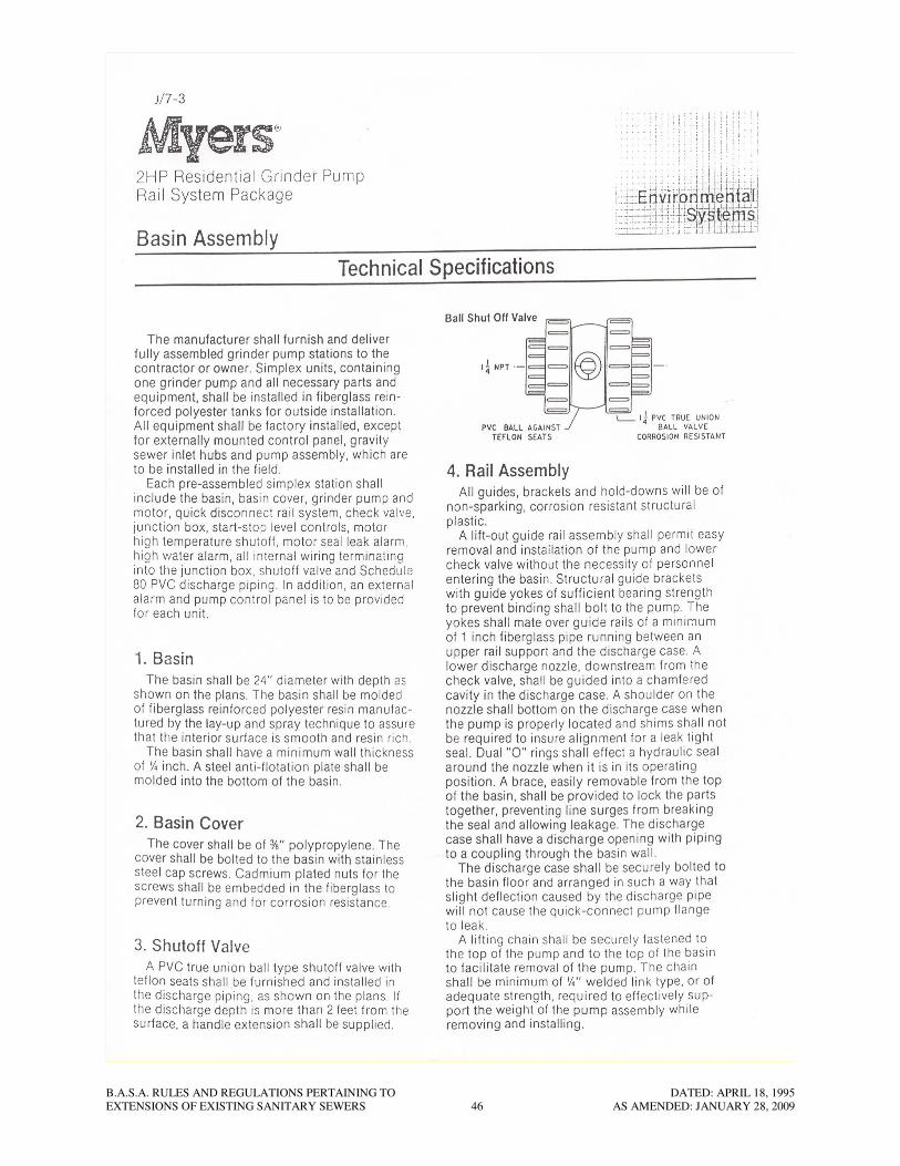
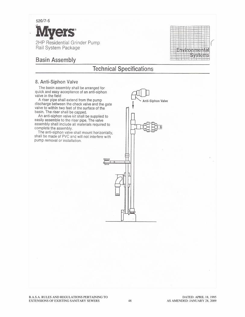
a. Each basin assembly shall include a PVC anti-siphon check valve. The anti-
siphon valve shall mount horizontally and shall not interfere with pump removal
or installation.
b. A basin inlet hub shall be included but not mounted on the basin. It shall be of
such a diameter that the bell end of a 6 in. Class 50 ductile iron mechanical joint
pipe can fit tightly onto the hub. The Contractor shall mount the hub in the field.
The Contractor shall install a section of 6 in. Class 50 ductile iron pipe at the
basin inlet hub. The length of the 6 in. ductile iron pipe shall be such that it
extends not less than 1 ft. past the excavation line and onto undisturbed earth but
in no event shall it be less than 10 ft. long. The manufacture shall provide, and
the Contractor shall install a 1/4 in. thick epoxy painted steel backing plate
conforming to the curvature of the basin. The backing plate shall be bolted to the
inlet hub from the inside of the basin with 4 sets of stainless steel bolts, nuts and
rubber washers.
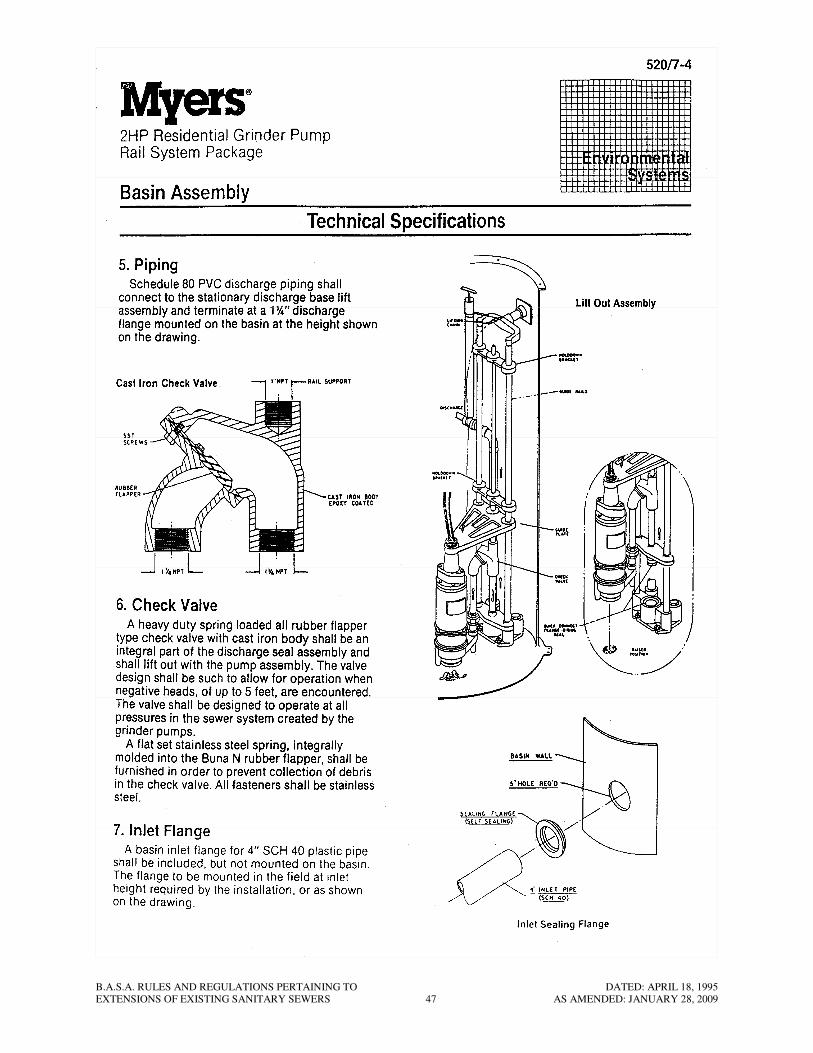
c. The manufacturer shall furnish a factory installed outlet hub suitable for the bell
end of a 4 in. Class 50 ductile iron casing pipe. In addition a 1/4 in. steel plate
B.A.S.A. RULES AND REGULATIONS PERTAINING TO DATED: APRIL 18, 1995
EXTENSIONS OF EXISTING SANITARY SEWERS 22 AS AMENDED: JANUARY 28, 2009
shall be molded in the basin wall at the discharge location. The outlet hub shall
be bolted to the steel plate with 4 sets of stainless steel bolts, nuts and rubber
washers. The Contractor shall install an adequate length of the 4 in. casing pipe
such that it extends not less than 1 ft. past the excavation line and onto
undisturbed earth, but in no event shall it be less than 10 ft. long. The Contractor
shall furnish and install rubber bushings to center the 1-1/2 in. discharge pipe
inside the 4 in. casing pipe.
32.3 Control Panel
a. There shall be a 106 db buzzer in the panel which shall also activate on high water
conditions. The buzzer shall sound for three minutes and then automatically
silence. The light shall remain on until the alarm condition is satisfied. A
screened opening shall be provided in the bottom of the panel so that the alarm
can be heard from the outside.
32.4 Level Control and Alarm Switches
a. Pump on and off levels shall be controlled by two mercury tube float type
switches. The mercury switch shall be sealed in a solid polyurethane float ball.
The support wire shall be 16-2SJOW (neoprene jacket) and a weight shall be
attached to the cord above the float to hold the switch in place in the basin.
b. The high water alarm switch shall be the same as the level control switches,
except that it shall be a different color than the pump level control switches.
c. The level controls shall be supported in the basin by a bracket and cord snubber
which will give positive support to the controls and allow flexibility in the set
levels.
d. All level controls shall be field checked by the Contractor to assure they are set at
the proper elevations.
32.5 Manufacturer’s Services and Testing
a. The grinder pump basins shall be installed in strict accordance with the
manufacturer’s recommendations. The Contractor shall provide the services of a
qualified manufacture’s representative to supervise the installation of basins as
deemed necessary by the Authority’s Representative.
b. Before being placed in operation each basin assembly shall be inspected and
approved by a qualified representative of the manufacturer in the presence of the
Authority’s Representative.
32.6 Supplies and Spare Parts
a. For each 10 grinder pumps, or fraction thereof, to be furnished on any Sewer
Extension, the following supplies and spare parts, properly packaged and labeled,
shall be furnished:
B.A.S.A. RULES AND REGULATIONS PERTAINING TO DATED: APRIL 18, 1995
EXTENSIONS OF EXISTING SANITARY SEWERS 23 AS AMENDED: JANUARY 28, 2009
(1) Two complete grinder pumps ready to slide into basin, including
discharge check valves, guide brackets, related piping, etc. or cash
equivalent at the option of Butler Area Sewer Authority.
(2) One fiberglass in-basin junction box.
(3) One basin cover.
(4) One discharge ball valve.
(5) Twelve O-rings for pump discharge nozzle.
(6) One amber lexan globe
(7) One upper pump seal and one lower pump seal.
(8) One complete control panel
(9) Twelve stainless steel bolts and washers for basin covers.
(10) Six of each of the following electrical components
fuses-each size
bulbs-each size
toggle switches-each type
(11) One manufacturer’s complete operation and maintenance manual.
32.7 Modifications to Residential Service
a. At each home which is to receive a grinder pump assembly, the Contractor shall
furnish and install an outside grinder pump service switch and alarm panel.
b. Electrically, the service switch and alarm panel shall be located on the load side
of the residential service meter box.
c. Underground power and control cables from the stand to the grinder pump basin
shall be 600 volt, multi-conductor, Class “B” stranded insulated copper
conductors. Conductor insulation shall be Type XHHW (Cross-linked
polyethylene) containing a continuous, impervious metallic sheath with outer
PVC jacket. The complete cable shall be suitable for direct burial.
d. Conduit Raceways – Conduit shall be rigid galvanized steel or intermediate metal
conduit (IMC). Conduit installed below grade shall be given a heavy coating of
bitumastic No. 50 coating compound prior to burial.
e. The Contractor shall install an indicator warning tape which shall be buried 12 in.
below grade above all electrical cable runs. The warning tape shall be yellow
plastic marker tape as manufactured by Pollard Co., Long Island, NY, or equal.
Tape shall read “Caution – Buried Electrical Cable Below”.
B.A.S.A. RULES AND REGULATIONS PERTAINING TO DATED: APRIL 18, 1995
EXTENSIONS OF EXISTING SANITARY SEWERS 24 AS AMENDED: JANUARY 28, 2009
f. The complete grinder pump service and alarm electrical systems shall be installed
and equipment and material shall be furnished in accordance with the latest
edition of the National Electric Code and State and local municipal codes and
ordinance.
33. INDIVIDUAL GRINDER PUMP INSTALLATIONS (Applicable to all installations and
systems approved after September 6, 2005).
33.1 If, and only if, gravity sewer service (basement or first floor only) is not available, the
Authority may permit the use of individual grinder pump and associated facilities for
sanitary sewage service on the gravity sewer system provided the title owner of the
lot on which the grinder pump is to be installed and used complies with the following
requirements:
a. The titled owner of the lot shall be responsible for all costs associated with the
design, administration, permitting, installation, operation, maintenance, repair and
replacement of the grinder pump unit, the private pressurized force main, and all
associated appurtenances. The private force main shall consist of the portion of
the discharge line from the grinder pump to the connection to the pressure sewer
system at the public sewer easement or public street right-of-way.
b. The grinder pump unit shall be equipped with an audible and visual alarm system
that will notify the owner/resident when the pump is not operating properly.
c. The force main connection to the Authority’s gravity sewer shall be made directly
into an Authority manhole by a cored drilling method with a flexible watertight
coupling approved by the Authority. In no case shall the line be installed in a
parallel occupancy along a public road or public right-of-way to avoid obtaining a
private right-of-way from neighboring properties.
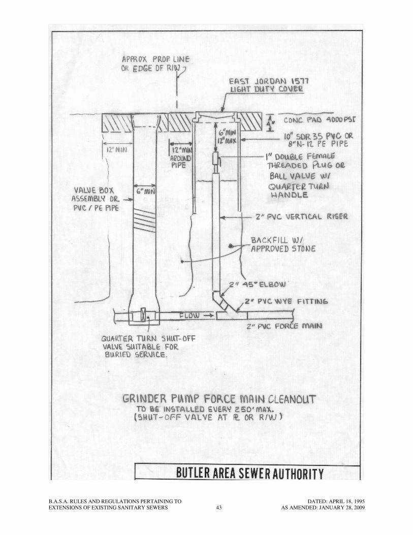
d. A shut-off valve and clean-out shall be installed at the property line or edge of
sanitary sewer easement in accordance with the attached Standard Drawing.
e. The Authority and its duly authorized agent shall have the right of access at all
reasonable hours to all parts of any premises connected with the sewer system for
the purpose of examining and inspecting the connections and fixtures, or for
disconnecting service for proper cause.
f. The Authority shall have no obligation at any time to own, operate, repair, replace
or maintain the private grinder pump and/or private force main. In the event the
titled owner fails to properly operate, maintain, repair, or replace the grinder
pump and/or private force main, the local Municipality shall be responsible for
enforcing its local Ordinances and using whatever means legally possible to
ensure proper operation, maintenance, and repair of the private grinder pump
and/or force main.
g. The titled owner shall record an easement over and through all properties, which
permits the local Municipality or its duly authorized agent to enter the property
and to perform emergency service to the grinder pump and/or force main.
B.A.S.A. RULES AND REGULATIONS PERTAINING TO DATED: APRIL 18, 1995
EXTENSIONS OF EXISTING SANITARY SEWERS 25 AS AMENDED: JANUARY 28, 2009
h. The titled owner shall comply with all other Authority Rules and Regulations and
other municipal ordinances as may be amended from time to time.
i. The titled owner shall enter an agreement with the Authority agreeing to the
conditions and requirements cited above. The Authority shall record this
agreement in the Butler County Recorder of Deeds Office.
j. The titled owner shall disclose the requirements of this agreement to any
prospective buyers and provide written notice to the Authority prior to any change
in ownership of any property served by a grinder pump.
34. GRINDER PUMP PRESSURE SEWER SYSTEMS (Applicable for all subdivisions or
land development plans approved after September 6, 2005)
34.1 If, and only if, gravity sewer service (basement or first floor only) is not available, the
Authority may permit the use of a pressure sewer system consisting of a common
force main and grinder pump units with discharge lines (private force mains) to
provide sanitary sewage service for a proposed subdivision or land development. The
developer/contractor, shall comply with all requirements of Part III, Chapter 29 (titled
Alternative Sewer Systems) of the “DOMESTIC WASTEWATER FACILITIES
MANUAL” as published by the Commonwealth of Pennsylvania, Department of
Environmental Protection, as well as the following requirements:
a. Each individual lot within the subdivision or land development shall be served by
an individual grinder pump unit.
b. No force mains shall be installed within any public street right-of-way without the
prior written consent and approval of the local municipality or the Pennsylvania
Department of Transportation. All force mains shall be installed within private
dedicated sanitary sewer or utility easements. The common force main
connection to the Authority’s gravity sewer shall be made directly into an
Authority manhole by core drilling method with a flexible, watertight coupling,
approved by the Authority.
c. The pressure sewer system shall be furnished and installed in full accordance with
all applicable Authority Rules and Regulations. Pressure sewer system must be
designed around a standard grinder pump unit specified by the Authority’s Rules
and Regulations, and the design of the proposed pressure sewer system must be
certified by a registered professional engineer and the manufacturer of the
specified grinder pump units.
d. The titled owner of each lot within the subdivision or land development shall be
responsible for the installation of the individual grinder pump units in accordance
with all of the requirements specified in Section 33, Subsections a through j,
except that connection to the common force main shall be made at the service
lateral provided by the Developer for each individual lot.
e. The Authority covenants to service and maintain the portion of the pressure sewer
system installed within the public sewer easement or public street right-of-way.
B.A.S.A. RULES AND REGULATIONS PERTAINING TO DATED: APRIL 18, 1995
EXTENSIONS OF EXISTING SANITARY SEWERS 26 AS AMENDED: JANUARY 28, 2009
f. The grinder pump units, including the wet well, valves, control panel, electrical
system and all appurtenances, and the private force main (as defined in section
33) shall be a totally privately owned, operated, and maintained by the titled
owner of the lots.
g. The Authority shall have no obligation at any time to own, operate, repair, replace
or maintain any grinder pump units or the private force mains located outside of
the public sewer easement or the public street right of way.
h. The Developer shall enter a developer’s agreement with the Authority agreeing to
the conditions and requirement cited above.
i. The Developer shall obtain all required state, county and municipal permits
applicable to the sanitary sewer system. The Pennsylvania Department of
Environmental Protection (DEP) may require that the Authority sign as the
applicant on the Water Quality Management Part II Sewer Extension and
Pumping Station Permit Application (hereinafter the “Permit”). Such request is
subject to Authority Board approval. Notwithstanding the Authority’s
designation as the applicant on the Permit, the Developer acknowledges and
understands that the Developer will be responsible for all obligations required
under the terms of the Permit.
j. The Developer shall agree that should the developer fail to design or construct the
pressure system in accordance with this Agreement, and/or should such
improvements fail to pass Authority’s testing and inspection, the Authority may
prohibit connection to its sanitary sewer system and will not be obligated to
accept sewage from the development. In addition, the Developer shall agree that
the Authority at is sole discretion, may request in writing to the DEP, that the
DEP cancel the Water Quality Management Permit.
B.A.S.A. RULES AND REGULATIONS PERTAINING TO DATED: APRIL 18, 1995
EXTENSIONS OF EXISTING SANITARY SEWERS 27 AS AMENDED: JANUARY 28, 2009
Butler Area Sewer Authority
Standard Drawings

B.A.S.A. RULES AND REGULATIONS PERTAINING TO DATED: APRIL 18, 1995
EXTENSIONS OF EXISTING SANITARY SEWERS 28 AS AMENDED: JANUARY 28, 2009
B.A.S.A. RULES AND REGULATIONS PERTAINING TO DATED: APRIL 18, 1995
EXTENSIONS OF EXISTING SANITARY SEWERS 29 AS AMENDED: JANUARY 28, 2009
B.A.S.A. RULES AND REGULATIONS PERTAINING TO DATED: APRIL 18, 1995
EXTENSIONS OF EXISTING SANITARY SEWERS 30 AS AMENDED: JANUARY 28, 2009
B.A.S.A. RULES AND REGULATIONS PERTAINING TO DATED: APRIL 18, 1995
EXTENSIONS OF EXISTING SANITARY SEWERS 31 AS AMENDED: JANUARY 28, 2009
B.A.S.A. RULES AND REGULATIONS PERTAINING TO DATED: APRIL 18, 1995
EXTENSIONS OF EXISTING SANITARY SEWERS 32 AS AMENDED: JANUARY 28, 2009
B.A.S.A. RULES AND REGULATIONS PERTAINING TO DATED: APRIL 18, 1995
EXTENSIONS OF EXISTING SANITARY SEWERS 33 AS AMENDED: JANUARY 28, 2009
B.A.S.A. RULES AND REGULATIONS PERTAINING TO DATED: APRIL 18, 1995
EXTENSIONS OF EXISTING SANITARY SEWERS 34 AS AMENDED: JANUARY 28, 2009
B.A.S.A. RULES AND REGULATIONS PERTAINING TO DATED: APRIL 18, 1995
EXTENSIONS OF EXISTING SANITARY SEWERS 35 AS AMENDED: JANUARY 28, 2009
B.A.S.A. RULES AND REGULATIONS PERTAINING TO DATED: APRIL 18, 1995
EXTENSIONS OF EXISTING SANITARY SEWERS 36 AS AMENDED: JANUARY 28, 2009
B.A.S.A. RULES AND REGULATIONS PERTAINING TO DATED: APRIL 18, 1995
EXTENSIONS OF EXISTING SANITARY SEWERS 37 AS AMENDED: JANUARY 28, 2009
B.A.S.A. RULES AND REGULATIONS PERTAINING TO DATED: APRIL 18, 1995
EXTENSIONS OF EXISTING SANITARY SEWERS 38 AS AMENDED: JANUARY 28, 2009

B.A.S.A. RULES AND REGULATIONS PERTAINING TO DATED: APRIL 18, 1995
EXTENSIONS OF EXISTING SANITARY SEWERS 39 AS AMENDED: JANUARY 28, 2009
B.A.S.A. RULES AND REGULATIONS PERTAINING TO DATED: APRIL 18, 1995
EXTENSIONS OF EXISTING SANITARY SEWERS 40 AS AMENDED: JANUARY 28, 2009
B.A.S.A. RULES AND REGULATIONS PERTAINING TO DATED: APRIL 18, 1995
EXTENSIONS OF EXISTING SANITARY SEWERS 41 AS AMENDED: JANUARY 28, 2009

B.A.S.A. RULES AND REGULATIONS PERTAINING TO DATED: APRIL 18, 1995
EXTENSIONS OF EXISTING SANITARY SEWERS 42 AS AMENDED: JANUARY 28, 2009
B.A.S.A. RULES AND REGULATIONS PERTAINING TO DATED: APRIL 18, 1995
EXTENSIONS OF EXISTING SANITARY SEWERS 43 AS AMENDED: JANUARY 28, 2009
B.A.S.A. RULES AND REGULATIONS PERTAINING TO DATED: APRIL 18, 1995
EXTENSIONS OF EXISTING SANITARY SEWERS 44 AS AMENDED: JANUARY 28, 2009

B.A.S.A. RULES AND REGULATIONS PERTAINING TO DATED: APRIL 18, 1995
EXTENSIONS OF EXISTING SANITARY SEWERS 45 AS AMENDED: JANUARY 28, 2009
B.A.S.A. RULES AND REGULATIONS PERTAINING TO DATED: APRIL 18, 1995
EXTENSIONS OF EXISTING SANITARY SEWERS 46 AS AMENDED: JANUARY 28, 2009
B.A.S.A. RULES AND REGULATIONS PERTAINING TO DATED: APRIL 18, 1995
EXTENSIONS OF EXISTING SANITARY SEWERS 47 AS AMENDED: JANUARY 28, 2009
B.A.S.A. RULES AND REGULATIONS PERTAINING TO DATED: APRIL 18, 1995
EXTENSIONS OF EXISTING SANITARY SEWERS 48 AS AMENDED: JANUARY 28, 2009

B.A.S.A. RULES AND REGULATIONS PERTAINING TO DATED: APRIL 18, 1995
EXTENSIONS OF EXISTING SANITARY SEWERS 49 AS AMENDED: JANUARY 28, 2009
B.A.S.A. RULES AND REGULATIONS PERTAINING TO DATED: APRIL 18, 1995
EXTENSIONS OF EXISTING SANITARY SEWERS 50 AS AMENDED: JANUARY 28, 2009