adidas - tokyu-sports.com · adidas - tokyu-sports.com ... adidas

15
RULE 1
Construction of FacilitiesThe facilities specifications listed in this rule represent the minimums necessary to host intercollegiate track and field. Technical information on construction, layout and marking is contained in the American Sports Builders Association Construction and Maintenance Manual and the International Association of Athletics Federations’ (IAAF) Track and Field Facilities Manual. The tolerances listed in those manuals are acceptable.
Track calculations and measurements, to verify compliance with NCAA rules, must be metric. Imperial distances, used within these rules for con-venience, are conversions from, approximations of, and less accurate than the stated metric values.Note: Figures are not drawn to scale.
SECTION 1. The TrackThe AreaARTICLE 1. With respect to grade or slope:a. The maximum lateral inclination permitted for the track across the full
width of the track, preferably toward the inside lane, and across all runways, shall not exceed 1:100, one percent (1%).
b. The maximum overall downward inclination permitted in the running direction for the track, the running direction for all runways and the throwing direction for all landing sectors, measured over the full length of any straight track distance, the last 20 meters of the javelin runway, the last 40 meters of other runways and the full length of landing sectors, shall not exceed 1:1,000, one-tenth of one percent (0.1%).
c. In the high jump, the maximum inclination of the last 15 meters of the approach and takeoff area shall not exceed 1:250, four-tenths of one percent (0.4%), in the running direction toward the center of the crossbar.

16 rule 1 / ConstruCtIon of faCIlItIes
d. The surface of a throwing circle shall be level.ARTICLE 2. The standard outdoor running track shall be 400 meters in length and not less than 6.40 meters in width. It shall normally consist of two parallel straights and two semicircular curves of equal design. Lanes shall be marked on both sides by white lines 5 centimeters wide. The lanes shall be numbered with lane one on the left when facing the finish line. Whenever possible, it is recommended that there be an obstacle-free zone on the inside and on the outside of the track at least 1 meter in width.
The track may be bordered on the inside by a curb of suitable material approximately 5 centimeters in height and a minimum of 5 centimeters in width. The edges of the curb shall be rounded. See Figure 1.
If a section of the curb must be temporarily removed for any reason, its place shall be marked by a white line 5 centimeters in width and by cones at least 15 centimeters in height. The cones shall be placed on the track so that the outward face of the cone coincides with the edge of the white line closest to the track. The cones shall be placed at distances not exceeding 4 meters.Note: For larger meets, nine lanes of 1.067 meters each are desirable.Track SurveyingARTICLE 3. Tracks shall be surveyed and all measurements certified after initial construction and after resurfacing. This certification shall be maintained and made available upon request.
A surveyor’s written certification shall list the exact measurements for the following:a. Levels of the track, runways, approaches and landing surfaces;b. Permanent track measurements;c. Start and finish lines;d. Track lanes;e. Baton-passing zones;f. Steeplechase water-jump pit;g. Hurdle placements; andh. Throwing surfaces — the shot put, hammer and discus circles, and the
javelin runway — and all sectors.Track MarkingsARTICLE 4. It is recommended that the following international color code be used when marking an indoor or outdoor track:

rule 1 / ConstruCtIon of faCIlItIes 17
a. Starting line (white)—55/60 meters, 55-/60-meter hurdles, 100 meters, 100-/110-meter hurdles, 200 meters, 300 meters, 400 meters, 1,500 meters, mile, 3,000 meters, steeplechase, 5,000 meters, 10,000 meters;
b. Starting line (white with green insert) — 800 meters, one-turn stagger;c. Starting line (white with red insert) — 800-meter relay, four-turn
stagger;d. Starting line (white with blue insert) — 1,600-meter relay, three-turn
stagger;e. Multiple waterfall starting lines (white);f. Finish line (white) — all;g. Relay exchange zones — 400-meter relay (yellow), 800-meter relay
(red), 1,600-meter relay (blue);h. Hurdle locations — 100 (yellow), 110 (blue), 400 (green), steeplechase
(black); andi. Break line (green).Measuring DistancesARTICLE 5. The distance to be run in any race shall be measured from start to finish between two theoretical hairlines. Lane one, and all distances not run in lanes, shall be measured 30 centimeters outward from the inner edge of the track if a regulation curb is in place. If a curb is not used, lane one shall be measured 20 centimeters from the left-hand lane line. For world, American and NCAA meet records, and championships qualifying, a regulation curb or cones must be in place. In races run on straightaway courses, the distance shall be measured in a straight line from the starting line to the finish line.
For all races in lanes around one or more curves, the distance to be run in each lane, except lane one, shall be measured 20 centimeters from the outer edge of the lane line that is on the runner’s left. Lane one is to be measured as stated above.Note: The measurement of lane staggers should be determined by a competent surveyor since they are not the same for races run entirely in lanes and races that use a break line. Additional variation occurs as the actual length of the straightaway varies. Tables for in-lane race staggers and break line race staggers with varying straightaways are available on the NCAA Web site.

18 rule 1 / ConstruCtIon of faCIlItIes
Figure 1—Track Measurements
DIRECTION OF RUNNING
— CURB —
MEASUREMENT LINEFIRST LANE
MEASUREMENT LINEALL OTHER LANES
— LANE LINE —
TRUE STARTING LINE TRUE FINISH LINE
5cm
30 cm
5cm
20 cm
1.06
7m
— LANE LINE —
Visible Starting LineARTICLE 6. A visible starting line, 5 centimeters wide, shall be marked on the track just within the measured distance so that its near edge is identical with the exactly measured and true starting line. See Figure 1.
The visible starting line for all races not run in lanes (including the 800 meters, when alleys are used) shall be curved so that all competitors run the same distance going into the curve. See Figure 2.Visible Finish LineARTICLE 7. A visible finish line, 5 centimeters wide, shall be marked on the track just outside the measured distance so that its edge nearer the start is identical with the exactly measured and true finish line. See Figure 1.
Lane numbers of reasonable size shall be placed at least 15 centimeters from the common finish line.
The intersection of each lane line and the finish line shall be painted black in a pattern to assist photo-finish lane identification. Figure 3 is an example.Note: A common finish line is recommended for all races. Lines in the finish area should be kept to a minimum. If additional lines are necessary, they should be of a less conspicuous color than the finish line, so as not to cause confusion.

rule 1 / ConstruCtIon of faCIlItIes 19
A
B
C
0.3m
The curved starting line may be established by driving a row ofpins 3.05 meters apart, 0.3 meters from the curb—the first pin tobe 0.3 meters from the curb at the start. For a 9.75-meter track,10 pins are sufficient.
Using a steel tape 30.48 meters or longer, and with the pin fur-thest from the start as a center, scribe an arc from pole to outercurb of track.
This will not be an arc of a circle as the radius will change asthe tape loses contact with each successive pin.
The distance for spacing of the pins—3.05 meters—is an arbi-trary and sufficiently accurate interval.
AB—Curved starting lineAC—Finish lineA—Juncture of straightaway and curve
Figure 2—Curved Starting Line
1 2 3 FINISH LINE
Figure 3—Finish-Line Intersections
Except where their use may interfere with fully automatic timing devices, two white posts may denote the finish line and be placed at least 30 centimeters from the edge of the track. The finish posts shall be of rigid construction, approximately 1.4 meters high and 5 to 8 centimeters in diameter.Running LanesARTICLE 8. a. In all races up to and including 400 meters, each contestant
shall have a separate lane to be marked by white lines of paint or suitable
20 rule 1 / ConstruCtIon of faCIlItIes
substance 5 centimeters in width. Lanes shall have the same width, with a recommended minimum of 1.067 (±0.01) meters (42 in.) and a maximum of 1.22 (±0.01) meters (48 in.), including the white line to the right. See Figure 1.
b. Hurdle lanes shall be at least 1.067 meters in width. If hurdle lanes are not marked on the track, they shall be judged as equivalent to 2 centimeters wider than the total width of the hurdles.
Break LineARTICLE 9. A visible break line 5 centimeters wide shall be an arc across the track at the entry of the back straight, showing the position at which competitors in the 800 meters and the second leg of the 1,600-meter relay are permitted to leave their respective lanes.
The arc of the break line should reflect an adjustment in each lane so that competitors in outside lanes travel the same distance to reach an inside position as competitors in the inside lanes. To assist competitors in identifying the break line, small cones shall be placed at the intersection of the lane lines and the break line.Relay ZonesARTICLE 10. In all relays around the track, the baton exchange must be made within a 20-meter zone, formed by lines drawn 10 meters on each side of the measured centerline. If designated by lines, the zone is between the edges of the lines closest to the start. All boxes or triangles denoting the limits of the zone shall be within the zone.International ZonesARTICLE 11. A distinctive short mark 10 meters before the passing zone shall be placed within, and indicate the beginning of, the international zone.In races which allow an international zone, outgoing runners, while waiting to receive the baton, may take a position and begin running anywhere within the zone. See Rule 5-8.4.

rule 1 / ConstruCtIon of faCIlItIes 21
SECTION 2. The HurdlesThe placement of hurdles shall be in accordance with the following
table:PLACEMENT OF HURDLES
No. of Hurdles
Distance Start to
1st Hurdle
Distance Between Hurdles
Distance Last Hurdle to
Finish55-Meter Hurdles (men) 5 13.72m 9.14m 4.72m55-Meter Hurdles (women) 5 13m 8.5m 8m60-Meter Hurdles (men) 5 13.72m 9.14m 9.72m60-Meter Hurdles (women) 5 13m 8.5m 13m100-Meter Hurdles 10 13m 8.5m 10.5m110-Meter Hurdles 10 13.72m 9.14m 14.02m400-Meter Hurdles 10 45m 35m 40m
SECTION 3. The SteeplechaseDistanceARTICLE 1. The standard distance for the steeplechase shall be 3,000 meters.JumpsARTICLE 2. There shall be 28 hurdle jumps and seven water jumps in cluded in the 3,000-meter event. The distance from the starting point to the finish line on the first lap shall not include any jumps. The water jump shall be the fourth jump in each lap. If necessary, the finish line shall be moved to accommodate this rule.Measuring CourseARTICLE 3. The following measurements are given as a guide, and any adjustments necessary shall be made by lengthening or shortening the distance at the starting point of the race. In this chart, it is assumed that a lap of 400 meters has been shortened 10 meters by constructing the water jump inside the track. It is recommended that the approach to and exit from the water-jump hurdle be straight for approximately 7 meters.

22 rule 1 / ConstruCtIon of faCIlItIes
POSSIBLE STEEPLECHASE MEASUREMENTSLap of 390 meters
Distance from starting point to commencement of 1st lap, to be run without jumps ................................................................................. 270m
Distance from start of 1st full lap to 1st hurdle .................................................. 10mFrom 1st to 2nd hurdle ....................................................................................... 78mFrom 2nd to 3rd hurdle ....................................................................................... 78mFrom 3rd hurdle to water jump ........................................................................... 78mFrom water jump to 4th hurdle ........................................................................... 78mFrom 4th hurdle to finish line ............................................................................. 68m 390m x 7 laps = 2,730m 3,000mNote: Since the water jump may be constructed on the area inside or outside the track, thereby lessening or lengthening the normal distance of the laps, it is not possible to prescribe any rule specifying the exact length of the laps or to state precisely the position of the water jump. It should be kept in mind that there must be enough distance from the starting line to the first hurdle to prevent the competitors from overcrowding, and there should be approximately 68 meters from the last hurdle to the finish line.Placement of Hurdles on TrackARTICLE 4. The hurdles shall be placed on the track so that 30 centimeters of the top bar, measured from the inside edge of the track, will extend inside the inner edge of the track. See Figure 4.Note: For hurdle specifications, see Rule 2-3.Water-Jump ConstructionARTICLE 5. It is recommended that the water jump be placed on the inside of the track. The water jump, including the hurdle, shall be 3.66 (±0.02) meters in length and 3.66 (±0.02) meters in width. The water shall be a minimum of 70 centimeters in depth immediately after the hurdle, and the pit shall have a constant upward slope from a point 30 centimeters past the water-jump hurdle to the level of the track at the far end. The landing surface inside the water jump should be composed of a nonskid, shock-absorbent material. A suitable material between the vertical uprights of the water-jump hurdle is recommended to aid the competitor with depth perception. See Figure 4.
The hurdle at the water jump shall be firmly fixed in front of the water and be of the same height as the other hurdles in the competition.

rule 1 / ConstruCtIon of faCIlItIes 23
For construction or resurfacing after January 1, 2008, the approach to and run-out from the water jump shall be of the same material as the track surface.
3.96m minimu m
Hurdl e
CONCRETE
CONCRETE
CO
NC
RE
TE
OUTLET TO DRAI N
3.66m
3.66m
MA TTING
1 .2-1. 4m
3.66m
Wa ter jump hurdle
.7 6 2
m (
±3m
m )
.9 1 4
m (
±3 m
m)
70cm
30cm
12.7cm
C O N C R E T E
M A T T IN G
(W OMEN ) (MEN )
Hurdle
30 cm 30 cm
Figure 4—W ater-Jump and Hurdle Measurements
SECTION 4. The High JumpApproachARTICLE 1. It is recommended that the approach be an octagon or square with a surface of at least 21 meters. The minimum length provided shall be 15 meters. The length of the approach run is unlimited.

24 rule 1 / ConstruCtIon of faCIlItIes
Takeoff AreaARTICLE 2. The takeoff area is the semicircle enclosed by a 3-meter radius whose center point is directly under the center of the crossbar. For a record to be approved, any point within this area may not exceed the tolerances. See Rule 1-1.1.
SECTION 5. The Pole VaultVaulting BoxARTICLE 1. The vaulting box in which the vaulting pole is planted shall be constructed of suitable rigid materials. Its dimensions and shape shall be those shown in the accompanying diagram.
The box shall be of a contrasting color from the runway and shall be immovably fixed in the ground so that all of its upper edges are flush with the takeoff area. The angle between the bottom of the box and the back of the box shall be 105 degrees. See Figure 5.RunwayARTICLE 2. For new construction after January 2006, the vaulting runway shall have a minimum length of 40 meters. It is recommended that the width of the runway be 1.22 (±0.01) meters. See Rule 1-1.1.Runway MarkingsARTICLE 3. The center of the runway, when marked after January 1, 2006, shall be marked with seven permanent lines in the pattern shown in Figure 6. Each line is 5 centimeters in width and 30 centimeters from an adjacent line. Each short line is 30 centimeters in length. The long line is 90 centimeters in length. The distance from the edge of the long line furthest from the landing pit to the point where the back of the vaulting box meets the runway is 3.70 meters.Runway MarkersARTICLE 4. The full length of the runway may be permanently marked with lines on or touching the edge that are not more than 2 centimeters wide by 5 centimeters long to indicate the distance from the back of the vaulting box.

rule 1 / ConstruCtIon of faCIlItIes 25
108.4cm6
0cm 120˚
15
cm
40
.8cm80cm
108cm20cm
30˚
100cm105˚
GROUNDLEVEL
22.4cm 20
cm
PLAN VIEW
VERTICAL SECTION
Figure 5—Pole-Vault Box
Figure 6—Pole-Vault Runway Markings
SECTION 6. The Long Jump and Triple JumpRunwayARTICLE 1. For new construction after January 2006, the minimum length of the runway for the long jump and triple jump shall be 40 meters from the edge nearest the pit of each event’s takeoff board. It is recommended that the width of the runway be 1.22 (±0.01) meters. The construction and material

26 rule 1 / ConstruCtIon of faCIlItIes
of the runway shall be extended beyond the takeoff board to the nearer edge of the landing pit. See Rule 1-1.1.
When the runway is not distinguishable from the adjacent surface, it is recommended that it be bordered by lines 5 centimeters in width from the start of the nearer edge of the landing pit.
The full length of the runway may be permanently marked with lines on or touching the edge that are not more than 2 centimeters wide and 5 centimeters long to indicate the distance from the foul line.Landing AreaARTICLE 2. The landing area in new construction after January 2006 shall be not less than 2.75 or more than 3 meters in width, and shall be filled with damp sand to an elevation identical in elevation with the takeoff board. Figure 7 shows an appropriate device for ensuring proper sand level.a. In the long jump, the distance between the takeoff board and the nearer
edge of the landing area shall be not less than 1 meter or greater than 3 meters. The distance between the foul line and the farther edge of the landing area shall be at least 10 meters.
b. In the triple jump, the nearer edge of the landing area shall be at least 11 meters from the foul line for men and 8.5 meters for women. Distances of 12.5 meters and 11 meters, respectively, are recommended.
SCRAPER BOARD
METAL FACE
FOUL LINE
TAKEOFFBOARD
LANDINGAREA
SAND LEVEL
TOP OF SIDE WALL
20cm
2.75-3.0m
Figure 7—Control of Sand Level in Long Jump and Triple Jump

rule 1 / ConstruCtIon of faCIlItIes 27
10 (±0.2) cm 20 (±0.2) cm
10cm MAX
DIRECTION OF RUN UP
13.75m m
1.22m FO UL M A RKE R
T AKEO F F B O AR D
Figure 8—Long-Jump and Triple-Jump Takeoff Board and Foul Marker
TakeoffARTICLE 3. The takeoff shall be a board made of wood or other suitable rigid material approximately 20 centimeters wide, at least 1.22 meters long and not more than 10 centimeters thick. The upper surface of the board must be level with the runway surface. This board shall be painted white and be firmly fixed in the runway.
In the absence of a takeoff board, the triple-jump takeoff area shall be approximately 20 centimeters wide and at least 1.22 meters long, and shall be painted white or firmly affixed (e.g., tape) on the all-weather runway.Foul LineARTICLE 4. The edge of the takeoff board nearest the landing pit shall be the foul line.Foul-Indicator AidARTICLE 5. For the purpose of aiding the calling of fouls:a. The area immediately beyond the foul line may be prepared as shown in
Figure 8. b. The foul may be detected by an electronic foul-line indicator with
validation by an image capturing system.
SECTION 7. The Throwing CirclesMaterialsARTICLE 1. The circles in throwing events shall be made of a band of metal or suitable rigid material, the top of which shall be flush with the concrete outside the circle. See Figures 10, 11 and 14. The interior surface should be
28 rule 1 / ConstruCtIon of faCIlItIes
of concrete or similar material and shall be 19 (±6) millimeters lower than the surface outside the circle.SectorARTICLE 2. Radial lines 5 centimeters wide shall form a 34.92-degree angle extended from the center of the circle. The inside edges of these lines shall mark the sector. For the discus and the hammer, sector flags should mark the ends of the lines and the sector shall be centered within the enclosure.
The level of the surface within the landing area shall be the same as the level of the surface of the throwing circle. See Rule 1-1.1.
The 34.92-degree sector may be laid out accurately by using the chart in Figure 9.DiametersARTICLE 3. The inside diameters of the shot-put, weight, and hammer-throw circles shall be 2.135 (±0.005) meters, and the diameter of the discus circle shall be 2.500 (±0.005) meters.CircleARTICLE 4. The circle shall be made of metal or suitable rigid material 6 millimeters in thickness and 19 (±6) millimeters in height, and be firmly secured flush with the throwing surface.Note: The IAAF stipulates a flanged circle 76 millimeters in height, imbedded below the throwing surface, to provide rigidity.InsertARTICLE 5. An insert may be used to convert a throwing circle from a 2.5-meter diameter to a 2.135-meter diameter. The insert shall be made of metal or suitable rigid material (rubber is not suitable) and be flush with the throwing surface. The height of the insert shall be 19 (±6) millimeters.Dividing LineARTICLE 6. All circles shall be divided in half by a 5-centimeter line extending not less than 75 centimeters from the outer edge of the circle to the end of the throwing pad and measured at right angles to the imaginary center of the throwing sector. Lines shall not be painted within any throwing circle.

rule 1 / ConstruCtIon of faCIlItIes 29
a a
b
34.92°
5
10
15
20
25
50
75
3
6
9
12
15
30
45
a (meters) b (meters)
Figure 9—Establishing the Sector
SECTION 8. The Shot-Put AreaCircleARTICLE 1. The circle shall be constructed in accordance with Figure 10. See Rule 1-7.StopboardARTICLE 2. The stopboard shall be an arc of wood, or other suitable materials, painted white and firmly fixed so that its inner edge coincides with the inner edge of the shot-put circle. It shall measure 1.21 (±0.01) meters in length along the chord between its endpoints, 112 millimeters and increasing to 300 millimeters in width, and 100 (±2) millimeters in height. See Figure 10.SectorARTICLE 3. See Rule 1-7.2.
SECTION 9. The Discus/Hammer AreaEnclosure
ARTICLE 1. All hammer and discus throws shall be made from an enclosure or cage that shall be centered on the circle and with the sector centered on the nonmovable cage opening, designed in such a way to provide adequate control of the implement landing and a fair venue for the throwers. Cage design is acknowledged to provide limited protection for spectators, officials and competitors. It does not ensure their safety. Exact

30 rule 1 / ConstruCtIon of faCIlItIes
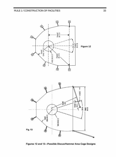
measurements and pole placements may vary based on local conditions and cage design, but must provide for the minimum distances specified. The following specifications are for the hammer or discus when thrown outside the stadium while spectators are present, or inside the stadium while other events are in progress, and should be considered a minimum configuration. All possible efforts shall be made to achieve the minimum configuration in the construction of new facilities after January 2006. Figures 12 and 13 provide illustrations of possible cage designs.a. The throwing circle shall be surrounded by a cage made with suitable
material, hung from and between rigid posts, sufficient to withstand and absorb an impact from the implement so that the implement will not escape over or through, and to reduce the possibility of the implement ricocheting or rebounding back toward the competitor. The purpose of the cage is to contain, but not interfere with, the flight path of the implement.
b. Rigid posts, approximately six in number, positioned in line with and to the rear of the front edge of the throwing circle, shall be approximately 4 meters from the center of the circle and allow for panels of suitable material between 2.74 and 2.90 meters in width that are at least 3.50 meters from the center of the circle. The height of these panels for the discus shall be at least 4 meters. The height of these panels for the hammer shall be at least 5 meters.
c. Panels of suitable material between 2.74 and 2.90 meters in width and at least 6.15 meters in height, shall be hung between each of the two rigid posts in line with the front edge of the throwing circle and each of two additional rigid posts toward the throwing sector that are not less than 2.85 meters away from the sector line. The location of these posts will be approximately 6 meters from the center of the throwing circle and provide a total fixed cage opening of between 8 and 9 meters.
d. When used for throwing the hammer, movable panels of suitable material not less than 4.20 meters in length and not less than 6.15 meters in height, shall be affixed to the rigid posts furthest from the circle toward the landing area. For a right-handed thrower (counter-clockwise rotation), the right movable panel is to be open so that it is parallel to the sector line on the right side and maintains the minimum 2.85-meter distance from the sector line. For a right-handed thrower, the left movable panel is placed in a position so that its non-pivot end is as perpendicular to the sector line as possible and is not greater than 1.5 meters into the sector
rule 1 / ConstruCtIon of faCIlItIes 31
and not less than 6 meters away from the center of the circle. For a left-handed thrower (clockwise rotation), the movable panel configuration is reversed.
e. Any area of flagging shall identify an implement landing danger zone of at least 55 degrees from the center of the throwing circle.
f. Cage configurations that are more restrictive than the minimums set forth in this rule may only be used with the consent of each participating institution.
Note 1: Whenever possible, the height of the panels of suitable material described in paragraphs c and d shall be increased. The recommended minimum height is 8 meters. Cages may have additional panels or designs to increase control of the implement landing area. Cages may be designed with an entry point at the rear of the cage.Note 2: The movable panel that is normally parallel to the sector line should be positioned closer to the sector line in cases in which the facility has the throwing area in close proximity to other event venues, so that greater control of the implement landing is achieved.Note 3: Cage design to allow for throwing both hammer and discus from the same cage is permitted. Circle placement, suitable material height and movable panel size and location, must achieve the overall goals indicated above, but these panels or designs may not create a restricted area for the thrower that is less than specified in this rule.Note 4: The height of the discus cage shall be at least 4 meters.

32 rule 1 / ConstruCtIon of faCIlItIes
2.135m ( ±5mm )
34.92˚
5cm PAINT OR
CHALK
76mm
SURFACE OF CIRCLE
GR OUND LEVEL
RING
6m m 19( ±6)mm
Figure 11—Hammer/Weight-Throw CircleNote: Lines shall not be inside the circle.
3.05m square
2.135m ( ±5mm )
34.92˚
5cm PAINT OR CHALK
METAL RING
SURFACE OF CIRCLE
GR OUND LEVEL
CONCRETE BLOCK LEVEL 19 ( ±6) mm
100 (±2) mm
112 ( ±2) mm
STOP BO ARD
75 cm min.
1.21
(±.
01)
m
R 1. 0675
112 (±2) mm
300 (±2) mm
Figure 10—Shot-Put CircleNote: Lines shall not be inside the circle.
3.05m square
rule 1 / ConstruCtIon of faCIlItIes 33
4.2 M(M
IN)
6.0 M(M
IN)
2.5 M D
IA
3.5 M R
AD
(MIN
)
8.0 M(M
IN)
34.92 Figure 12

34 rule 1 / ConstruCtIon of faCIlItIes
CircleARTICLE 2. The circle for the hammer shall be constructed in accordance with Figure 11. The circle for the discus shall be constructed in accordance with Figure 14. See Rule 1-7.SectorARTICLE 3. See Rule 1-7.2.
2.50m ( ± 5mm)
34.9 2 ̊
5cm
76mm
SURF ACE OF CIRCLE
19 ( ± 6) mm
GROUND LEVE L
RING
6m m
3.05m square
P AINT OR CHALK
Figure 14—Discus CircleHammer requires an insert in the circle (see Figure 11 and Rule 1-7.5).
Note: Lines shall not be inside the circle.
SECTION 10. The Weight-Throw AreaThe weight throw is an indoor event. It may be contested outdoors. For
construction of facilities, see Figure 11 and Rule 10-8.

rule 1 / ConstruCtIon of faCIlItIes 35
SECTION 11. The Javelin AreaRunwayARTICLE 1. The runway shall be marked by two parallel lines 5 centimeters in width. The minimum length shall be 33.5 meters and the width shall be 4 meters between the inside edges of the marked parallel lines. It is recommended that the runway be constructed of an artificial surface for its entire length. If an artificial surface is used, it is recommended that the runway be extended 1 meter beyond the foul line for safety reasons.
The full length of the runway may be permanently marked with lines on or touching the edge that are not more than 2 centimeters wide and 5 centimeters long to indicate the distance from the foul line.Foul LineARTICLE 2. The foul line shall be 7 centimeters wide, painted white, and shall be made in the shape of an arc with a radius of 8 meters. The distance between its extremities shall be 4 meters, measured straight across from end to end. Lines shall be drawn from the extremities of the arc at right angles to the parallel lines marking the runway. These lines should be 75 centimeters in length and 7 centimeters wide.SectorARTICLE 3. Radial lines 5 centimeters wide shall be extended from the center of the circle of which the arc of the foul line is a part through the extremities of the arc. The inside edges of these lines shall mark the sector. The surface within the landing area shall be on the same level as the throwing surface. See Rule 1-1.1. Sector flags should mark the ends of the lines. See Figure 15.
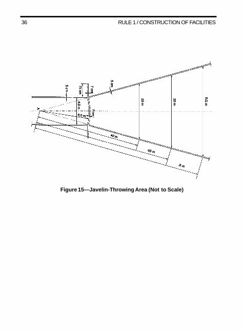
36 rule 1 / ConstruCtIon of faCIlItIes
Figure 15—Javelin-Throwing Area (Not to Scale)