RUGGEDCOM WIN5151 Technical Specifications 3 4 5 · Technical Specifications 3 ... Technical...
36
RUGGEDCOM WIN5151 Installation Guide 08/2015 Preface Introduction 1 Installing the Device 2 Technical Specifications 3 Dimension Drawings 4 Certification 5 RC1189-EN-02
Transcript of RUGGEDCOM WIN5151 Technical Specifications 3 4 5 · Technical Specifications 3 ... Technical...
RUGGEDCOM WIN5151
Installation Guide
08/2015
Preface
Introduction 1
Installing the Device 2
Technical Specifications 3
Dimension Drawings 4
Certification 5
RC1189-EN-02
RUGGEDCOM WIN5151Installation Guide
ii
Copyright © 2015 Siemens Canada Ltd.
All rights reserved. Dissemination or reproduction of this document, or evaluation and communication of its contents, is not authorizedexcept where expressly permitted. Violations are liable for damages. All rights reserved, particularly for the purposes of patent application ortrademark registration.
This document contains proprietary information, which is protected by copyright. All rights are reserved. No part of this document may bephotocopied, reproduced or translated to another language without the prior written consent of Siemens Canada Ltd..
Disclaimer Of LiabilitySiemens has verified the contents of this manual against the hardware and/or software described. However, deviations between the productand the documentation may exist.
Siemens shall not be liable for any errors or omissions contained herein or for consequential damages in connection with the furnishing,performance, or use of this material.
The information given in this document is reviewed regularly and any necessary corrections will be included in subsequent editions. Weappreciate any suggested improvements. We reserve the right to make technical improvements without notice.
Registered TrademarksROX™, Rugged Operating System On Linux™, CrossBow™ and ELAN™ are trademarks of Siemens Canada Ltd. ROS® is a registeredtrademark of Siemens Canada Ltd.
Other designations in this manual might be trademarks whose use by third parties for their own purposes would infringe the rights of theowner.
Security InformationSiemens provides products and solutions with industrial security functions that support the secure operation of plants, machines, equipmentand/or networks. They are important components in a holistic industrial security concept. With this in mind, Siemens' products and solutionsundergo continuous development. Siemens recommends strongly that you regularly check for product updates.
For the secure operation of Siemens products and solutions, it is necessary to take suitable preventive action (e.g. cell protection concept)and integrate each component into a holistic, state-of-the-art industrial security concept. Third-party products that may be in use should alsobe considered. For more information about industrial security, visit http://www.siemens.com/industrialsecurity.
To stay informed about product updates as they occur, sign up for a product-specific newsletter. For more information, visit http://support.automation.siemens.com.
WarrantySiemens warrants this product for a period of five (5) years from the date of purchase, conditional upon the return to factory for maintenanceduring the warranty term. This product contains no user-serviceable parts. Attempted service by unauthorized personnel shall render allwarranties null and void. The warranties set forth in this article are exclusive and are in lieu of all other warranties, performance guaranteesand conditions whether written or oral, statutory, express or implied (including all warranties and conditions of merchantability and fitness fora particular purpose, and all warranties and conditions arising from course of dealing or usage or trade). Correction of nonconformities in themanner and for the period of time provided above shall constitute the Seller’s sole liability and the Customer’s exclusive remedy for defectiveor nonconforming goods or services whether claims of the Customer are based in contract (including fundamental breach), in tort (includingnegligence and strict liability) or otherwise.
For warranty details, visit www.siemens.com/ruggedcom or contact a Siemens customer service representative.
Contacting SiemensAddressSiemens Canada Ltd.Industry Sector300 Applewood CrescentConcord, OntarioCanada, L4K 5C7
TelephoneToll-free: 1 888 264 0006Tel: +1 905 856 5288Fax: +1 905 856 1995
Webwww.siemens.com/ruggedcom
RUGGEDCOM WIN5151Installation Guide
Table of Contents
iii
Table of ContentsPreface ................................................................................................................ v
Alerts .................................................................................................................................................. vRelated Documents ............................................................................................................................. vAccessing Documentation ................................................................................................................... viTraining .............................................................................................................................................. viCustomer Support .............................................................................................................................. vi
Chapter 1
Introduction .......................................................................................................... 1
1.1 Feature Highlights ........................................................................................................................ 11.2 Configuration Ports and Indicator LEDs ......................................................................................... 21.3 Antennas ..................................................................................................................................... 3
Chapter 2
Installing the Device ............................................................................................ 5
2.1 Mounting the Device .................................................................................................................... 62.1.1 Mounting the Device to a Pole ........................................................................................... 72.1.2 Mounting the Device to a Wall or Tower .............................................................................. 8
2.2 Installing the Antenna ................................................................................................................... 82.3 Assembling the PoE Cable ......................................................................................................... 102.4 Connecting the WIN1010 Data Adapter ....................................................................................... 132.5 Connecting to a RUGGEDCOM RP100 or RP110 ........................................................................ 152.6 Installing the Device in Hazardous Locations ............................................................................... 162.7 Grounding the Device ................................................................................................................. 172.8 Weatherproofing the Device ........................................................................................................ 172.9 Configuring the CPE .................................................................................................................. 19
Chapter 3
Technical Specifications ..................................................................................... 21
3.1 Power Consumption ................................................................................................................... 213.2 Operating Environment ............................................................................................................... 213.3 Mechanical Specifications ........................................................................................................... 213.4 IDU to ODU Cable Specifications ................................................................................................ 22
Table of Contents
RUGGEDCOM WIN5151Installation Guide
iv
Chapter 4
Dimension Drawings .......................................................................................... 25
Chapter 5
Certification ........................................................................................................ 27
5.1 Standards Compliance ............................................................................................................... 275.2 Agency Approvals ...................................................................................................................... 275.3 MIL-STD Ratings ........................................................................................................................ 285.4 IEEE 802.16e Mobile WiMAX Compliance ................................................................................... 285.5 Environmental Type Tests ........................................................................................................... 28
RUGGEDCOM WIN5151Installation Guide
Preface
Alerts v
PrefaceThis guide describes the RUGGEDCOM WIN5151. It describes the major features of the device, installation,commissioning and important technical specifications.
It is intended for use by base station installers and operators, and assumes readers have a working knowledgeof WiMAX technologies and procedures. While some safety precautions are reviewed here, it is assumed thatinstallers are trained in safe installation practices. Users unfamiliar with safe installation procedures, WiMAXtechnologies, and service procedures should not rely on this manual for comprehensive guidance.
AlertsThe following types of alerts are used when necessary to highlight important information.
DANGER!DANGER alerts describe imminently hazardous situations that, if not avoided, will result in death orserious injury.
WARNING!WARNING alerts describe hazardous situations that, if not avoided, may result in serious injury and/orequipment damage.
CAUTION!CAUTION alerts describe hazardous situations that, if not avoided, may result in equipment damage.
IMPORTANT!IMPORTANT alerts provide important information that should be known before performing a procedureor step, or using a feature.
NOTENOTE alerts provide additional information, such as facts, tips and details.
Related DocumentsOther documents that may be of interest include:
• RUGGEDCOM CPE User Guide
• RUGGEDCOM RP100 Installation Guide
• RUGGEDCOM RP110 Installation Guide

Preface
RUGGEDCOM WIN5151Installation Guide
vi Accessing Documentation
Accessing DocumentationThe latest Hardware Installation Guides and Software User Guides for most RUGGEDCOM products areavailable online at www.siemens.com/ruggedcom.
For any questions about the documentation or for assistance finding a specific document, contact a Siemenssales representative.
TrainingSiemens offers a wide range of educational services ranging from in-house training of standard courses onnetworking, Ethernet switches and routers, to on-site customized courses tailored to the customer's needs,experience and application.
Siemens' Educational Services team thrives on providing our customers with the essential practical skills to makesure users have the right knowledge and expertise to understand the various technologies associated with criticalcommunications network infrastructure technologies.
Siemens' unique mix of IT/Telecommunications expertise combined with domain knowledge in the utility,transportation and industrial markets, allows Siemens to provide training specific to the customer's application.
For more information about training services and course availability, visit www.siemens.com/ruggedcom orcontact a Siemens sales representative.
Customer SupportCustomer support is available 24 hours, 7 days a week for all Siemens customers. For technical support orgeneral information, contact Siemens Customer Support through any of the following methods:
OnlineVisit http://www.siemens.com/automation/support-request to submit a Support Request (SR) orcheck on the status of an existing SR.
TelephoneCall a local hotline center to submit a Support Request (SR). To locate a local hotline center, visithttp://www.automation.siemens.com/mcms/aspa-db/en/automation-technology/Pages/default.aspx.
Mobile AppInstall the Industry Online Support app by Siemens AG on any Android, Apple iOS or Windowsmobile device and be able to:
• Access Siemens' extensive library of support documentation, including FAQs and manuals• Submit SRs or check on the status of an existing SR• Contact a local Siemens representative from Sales, Technical Support, Training, etc.• Ask questions or share knowledge with fellow Siemens customers and the support community
RUGGEDCOM WIN5151Installation Guide
Chapter 1Introduction
Feature Highlights 1
IntroductionThe RUGGEDCOM WIN5151 Outdoor Unit (ODU) Customer Premises Equipment (CPE) device is part of theRUGGEDCOM WIN family, a line of mobile WiMAX broadband wireless access systems based on the IEEE802.16e mobile WiMAX standard.
The RUGGEDCOM WIN5151 is a high-performance, self-learning subscriber. It automatically detects the basestation on the best signal available allowing for plug and play installation and maintenance free operation. Theautomatic switching and monitoring features guarantee on-going operation in changing conditions, which resultsin low maintenance and considerable operating expense savings.
The device is compliant to the IEEE 802.16e standards to effectively meet the unique requirements of thewireless Metropolitan Area Network (MAN) environment and to deliver broadband access services to a widerange of customers. Specifically designed for point-to-multipoint broadband wireless access applications,the RUGGEDCOM WIN5151 provides efficient use of the wireless spectrum, supporting a range of userenvironments.
The RUGGEDCOM WIN5151 Outdoor Unit (ODU) Customer Premises Equipment (CPE) device also complieswith the IEEE 802.16-2005 standard for the deployment of point-to-multipoint (PMP) and point-to-point (PTP)network architectures.
The device is a WiMAX Forum IEEE 802.16e Wave 2 (MIMO) certified subscriber. Each subscriber registers andestablishes a bi-directional data link with the base station.
The following sections provide more information about the device:
• Section 1.1, “Feature Highlights”
• Section 1.2, “Configuration Ports and Indicator LEDs”
• Section 1.3, “Antennas”
Section 1.1
Feature HighlightsLong RangeThe device has multiple built-in receivers to improve range and Non-Line-of-Sight (NLoS) performance. Thesystem has the ability to leverage sub-channelization technology to balance links with high-power base stations.
Robust DesignThe device is designed for mission critical applications in harsh environments with very high Mean Time BeforeFailure.
Quality of ServiceThe device gives the user the ability to separate traffic types over the air, and guarantee latency, minimumbandwidth and jitter according to application needs.
FlexibilityThe device supports both IP convergence sublayer for wireless Internet service providers or EthernetConvergence Sublayer, ideal for mission critical private networks.
Chapter 1Introduction
RUGGEDCOM WIN5151Installation Guide
2 Configuration Ports and Indicator LEDs
Radio and Modem Features• Supported Frequency Bands: 5251, 5151, 7251
• Radio Access Method: IEEE802.16-2005 (16e OFDMA)
• Operation Mode: TDD
• Compatibility: Wave 2 Profile (MIMO)
• Frequency Resolution: 0.25 MHz
• Antenna Diversity Support: STC/MRC/MIMO
• FFT/Modulation: 1024/512 FFT points; QPSK, 16 QAM, 64 QAM
• FEC: Convolutional Turbo Code
• Dynamic Range:
RX: -100 dBm: -20 dBm
TX: -30 dBm: +24 dBm
Section 1.2
Configuration Ports and Indicator LEDsConnectors and LED indicators are found on the bottom of the device casing.
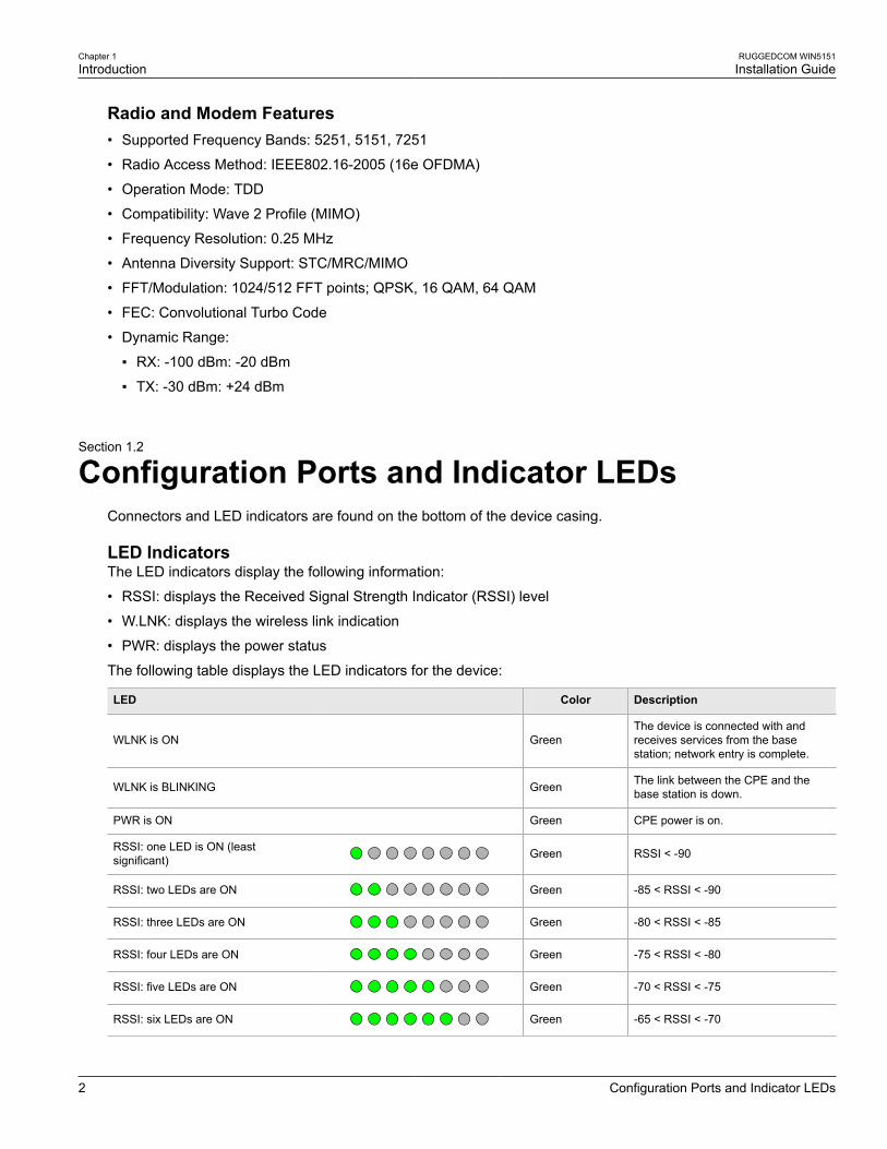
LED IndicatorsThe LED indicators display the following information:
• RSSI: displays the Received Signal Strength Indicator (RSSI) level
• W.LNK: displays the wireless link indication
• PWR: displays the power status
The following table displays the LED indicators for the device:
LED Color Description
WLNK is ON GreenThe device is connected with andreceives services from the basestation; network entry is complete.
WLNK is BLINKING Green The link between the CPE and thebase station is down.
PWR is ON Green CPE power is on.
RSSI: one LED is ON (leastsignificant) Green RSSI < -90
RSSI: two LEDs are ON Green -85 < RSSI < -90
RSSI: three LEDs are ON Green -80 < RSSI < -85
RSSI: four LEDs are ON Green -75 < RSSI < -80
RSSI: five LEDs are ON Green -70 < RSSI < -75
RSSI: six LEDs are ON Green -65 < RSSI < -70
RUGGEDCOM WIN5151Installation Guide
Chapter 1Introduction
Antennas 3
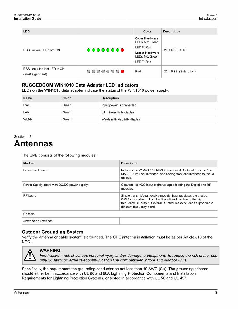
LED Color Description
RSSI: seven LEDs are ON
Older HardwareLEDs 1-7: Green
LED 8: Red
Latest HardwareLEDs 1-6: Green
LED 7: Red
-20 < RSSI < -60
RSSI: only the last LED is ON
(most significant)Red -20 < RSSI (Saturation)
RUGGEDCOM WIN1010 Data Adapter LED IndicatorsLEDs on the WIN1010 data adapter indicate the status of the WIN1010 power supply.
Name Color Description
PWR Green Input power is connected
LAN Green LAN link/activity display
WLNK Green Wireless link/activity display
Section 1.3
AntennasThe CPE consists of the following modules:
Module Description
Base-Band board: Includes the WiMAX 16e MIMO Base-Band SoC and runs the 16eMAC + PHY, user interface, and analog front end interface to the RFmodule.
Power Supply board with DC/DC power supply: Converts 48 VDC input to the voltages feeding the Digital and RFmodules.
RF board: Single transmit/dual receive module that modulates the analogWiMAX signal input from the Base-Band modem to the highfrequency RF output. Several RF modules exist, each supporting adifferent frequency band.
Chassis
Antenna or Antennas:
Outdoor Grounding SystemVerify the antenna or cable system is grounded. The CPE antenna installation must be as per Article 810 of theNEC.
WARNING!Fire hazard – risk of serious personal injury and/or damage to equipment. To reduce the risk of fire, useonly 26 AWG or larger telecommunication line cord between indoor and outdoor units.
Specifically, the requirement the grounding conductor be not less than 10 AWG (Cu). The grounding schemeshould either be in accordance with UL 96 and 96A Lightning Protection Components and InstallationRequirements for Lightning Protection Systems, or tested in accordance with UL 50 and UL 497.

RUGGEDCOM WIN5151Installation Guide
Chapter 1Introduction
Antennas 4
RUGGEDCOM WIN5151Installation Guide
Chapter 2Installing the Device
5
Installing the DeviceThis chapter describes how to install the device, including mounting the device, connecting power, connecting theantenna, and connecting the device to the network.
DANGER!Electrocution hazard – risk of serious personal injury and/or damage to equipment. Before performingany maintenance tasks, make sure all power to the device has been disconnected and waitapproximately two minutes for any remaining energy to dissipate.
DANGER!Electrocution hazard – risk of death or serious injury. When the base station is installed in an outdoorlocation, all indoor components (e.g. Ethernet and power supply) should be connected through alightning protector.
Lightning protection protects people and equipment located indoors from lightning that may strike thebase station or its outdoor cables. Therefore, install the lightning protector base station indoors, asclose as possible to the point where the cables enter the building. The lightning protector can also beinstalled outdoors as long as the cables that lead indoors are well protected from lightning between theprotector and the building entrance.
WARNING!Safety hazard – risk of serious personal injury and/or damage to equipment. Installing theRUGGEDCOM WIN5151 can pose a serious safety hazard. Be sure to take precautions to avoid thefollowing:
• Exposure to high voltage lines during installation
• Falling when working at heights or with ladders
• Injuries from dropping tools
• Contact with AC wiring (power system connection)
IMPORTANT!Only certified personnel should be permitted to install equipment.
IMPORTANT!This product contains no user-serviceable parts. Attempted service by unauthorized personnel shallrender all warranties null and void.
Changes or modifications not expressly approved by Siemens Canada Ltd. could invalidatespecifications, test results, and agency approvals, and void the user's authority to operate theequipment.
IMPORTANT!This product should be installed in a restricted access location where access can only be gained byauthorized personnel who have been informed of the restrictions and any precautions that must betaken. Access must only be possible through the use of a tool, lock and key, or other means of security,and controlled by the authority responsible for the location.
Chapter 2Installing the Device
RUGGEDCOM WIN5151Installation Guide
6 Mounting the Device
IMPORTANT!Install equipment in accordance with the electrical code relevant to the country of installation, such as:
• the National Electrical Code (NEC), ANSI/NFPA 70
• the Canadian Electrical Code (CEC), Part 1, CSA C22.1
• the National Electrical Safety Code IEEE C2 (when applicable)
Unless marked or otherwise identified, the Standard for the Protection of Electronic Computer/DataProcessing Equipment, ANSI/NFPA 75, also applies.
IMPORTANT!Outdoor exposed communication lines longer than 40 m (140 ft) must be considered as TNV-1 circuits.The installer must make sure the power supply and network ports are designed for full compliance withthe standards for TNV-1 telecommunication networks.
The general procedure for installing the device is as follows:
1. Mount the device to a pole or wall.
2. Install and connect the antenna.
3. Assemble the PoE cable.
4. Connect a RUGGEDCOM WIN1010 adapter.
5. Connect a RUGGEDCOM RP100/RP110.
6. If the device is to be installed in a hazardous location, install the Class I, Division II kit.
7. Make sure the device is grounded.
8. Weatherproof the ends of all cables.
9. Configure the device.
These steps, and other related information, are described in the following sections:
• Section 2.1, “Mounting the Device”
• Section 2.2, “Installing the Antenna”
• Section 2.4, “Connecting the WIN1010 Data Adapter ”
• Section 2.5, “Connecting to a RUGGEDCOM RP100 or RP110 ”
• Section 2.6, “Installing the Device in Hazardous Locations”
• Section 2.7, “Grounding the Device”
• Section 2.3, “Assembling the PoE Cable”
• Section 2.8, “Weatherproofing the Device”
• Section 2.9, “Configuring the CPE”
Section 2.1
Mounting the DeviceThe RUGGEDCOM WIN5151 is designed for maximum mounting and display flexibility. It can be secured to abracket and then mounted to a pole or to a wall or tower.
RUGGEDCOM WIN5151Installation Guide
Chapter 2Installing the Device
Mounting the Device to a Pole 7
NOTEFor detailed dimensions of the device, refer to Chapter 4, Dimension Drawings.
The following sections describe the various methods of mounting the device, and how to install the mountingbracket:
• Section 2.1.1, “Mounting the Device to a Pole”
• Section 2.1.2, “Mounting the Device to a Wall or Tower”
The RUGGEDCOM WIN5151 ODU CPE mounting kit allows for pole or wall mounting.
When choosing the mounting location for the unit, consider the available mounting structures and antennaclearance.
Site SurveyMost wireless networks include many CPEs and BSTs installed in various locations in an overlapping radio-cell pattern. It is important to position each CPE at an optimal location considering the assignment of its radiochannels. Therefore, a site survey becomes an essential first step before physically deploying the RUGGEDCOMWIN5151 solution.
The site survey should include details important to the planning of the CPE deployment in each specific site,including potential mounting points for CPE and antennas, as well as the routing options for data, power andantenna cables.
Recommended Site RequirementsIt is highly recommended the RUGGEDCOM WIN5151 be mounted with as few obstructions as possible betweenthe CPE and the base station. The CPE should be pointed in the direction of the designated server base station.When choosing the ideal location, it is also important to take into consideration the overall area topology.
Section 2.1.1
Mounting the Device to a PoleThe device can be attached to any pipe or pole with a diameter of 44.5 to 254 mm (1.75 to 10 in).
To mount the device to a pole, do the following:
1. Select a mounting location on the pole.
2. Position the mounting bracket against the pole.
3. Secure the clamping bracket to the mounting bracket using screws, spring washers and nuts. Make sure thescrews are hand tightened.
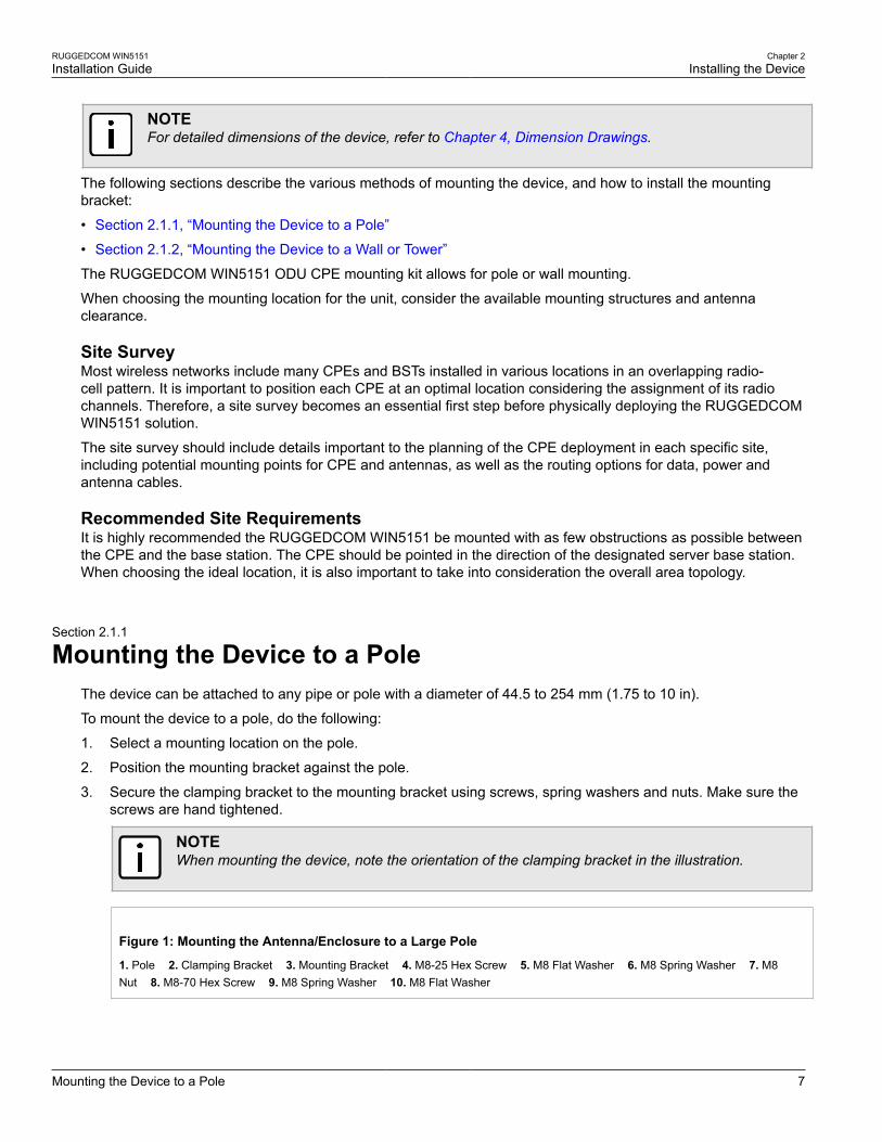
NOTEWhen mounting the device, note the orientation of the clamping bracket in the illustration.
Figure 1: Mounting the Antenna/Enclosure to a Large Pole
1. Pole 2. Clamping Bracket 3. Mounting Bracket 4. M8-25 Hex Screw 5. M8 Flat Washer 6. M8 Spring Washer 7. M8Nut 8. M8-70 Hex Screw 9. M8 Spring Washer 10. M8 Flat Washer
Chapter 2Installing the Device
RUGGEDCOM WIN5151Installation Guide
8 Mounting the Device to a Wall or Tower
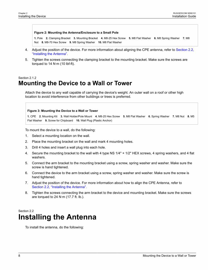
Figure 2: Mounting the Antenna/Enclosure to a Small Pole
1. Pole 2. Clamping Bracket 3. Mounting Bracket 4. M8-25 Hex Screw 5. M8 Flat Washer 6. M8 Spring Washer 7. M8Nut 8. M8-70 Hex Screw 9. M8 Spring Washer 10. M8 Flat Washer
4. Adjust the position of the device. For more information about aligning the CPE antenna, refer to Section 2.2,“Installing the Antenna”.
5. Tighten the screws connecting the clamping bracket to the mounting bracket. Make sure the screws aretorqued to 14 N·m (10 lbf-ft).
Section 2.1.2
Mounting the Device to a Wall or TowerAttach the device to any wall capable of carrying the device's weight. An outer wall on a roof or other highlocation to avoid interference from other buildings or trees is preferred.
Figure 3: Mounting the Device to a Wall or Tower
1. CPE 2. Mounting Kit 3. Wall Holder/Pole Mount 4. M8-25 Hex Screw 5. M8 Flat Washer 6. Spring Washer 7. M8 Nut 8. M5Flat Washer 9. Screw for Chipboard 10. Wall Plug (Plastic Anchor)
To mount the device to a wall, do the following:
1. Select a mounting location on the wall.
2. Place the mounting bracket on the wall and mark 4 mounting holes.
3. Drill 4 holes and insert a wall plug into each hole.
4. Secure the mounting bracket to the wall with 4 type NS 1/4" × 1/2" HEX screws, 4 spring washers, and 4 flatwashers.
5. Connect the arm bracket to the mounting bracket using a screw, spring washer and washer. Make sure thescrew is hand tightened.
6. Connect the device to the arm bracket using a screw, spring washer and washer. Make sure the screw ishand tightened.
7. Adjust the position of the device. For more information about how to align the CPE Antenna, refer toSection 2.2, “Installing the Antenna”.
8. Tighten the screws connecting the arm bracket to the device and mounting bracket. Make sure the screwsare torqued to 24 N·m (17.7 ft. lb.).
Section 2.2
Installing the AntennaTo install the antenna, do the following:

RUGGEDCOM WIN5151Installation Guide
Chapter 2Installing the Device
Installing the Antenna 9
WARNING!Radiation hazard – risk of Radio Frequency (RF) exposure. This base station is compliant withthe requirements set forth in CFR 47, section 1.1307, addressing Radio Frequency (RF) exposurefrom radio frequency base stations, as defined in FCC OET Bulletin 65 FCC OET Bulletin 65 [http://transition.fcc.gov/Bureaus/Engineering_Technology/Documents/bulletins/oet65/oet65.pdf]. The emittedradiation should be as little as possible. To achieve minimum RF exposure, install the base stationwhen it is configured not to transmit and set it to operational mode remotely, rather than having atechnician enable transmission on-site. For maintenance of the base station, or other operations whichrequire RF exposure, the exposure should be minimized in time and according to the regulations set bythe FCC or the regulations relevant to the country of installation.
IMPORTANT!During antenna installation, observe the following:
• Antenna must be in a fixed position.
• After it is installed, do not change the antenna position.
NOTEThe device is compliant with the requirements set forth in CFR 47, section 1.1307, addressing RadioFrequency (RF) exposure from radio frequency devices as defined in OET Bulletin 65. The emittedradiation should be as little as possible. To achieve minimum RF exposure, install the device when itis configured not to transmit and set it to operational mode remotely, rather than enabling transmissionby the installer on-site. For maintenance of the device, or other operations which require RF exposure,minimize the exposure time according to the regulations set by the FCC or the regulations relevant tothe country of installation.
IMPORTANT!Make sure the front of the is always facing the base station. In some conditions, such as when the lineof sight to the base station is impeded, better reception may be achieved using a reflected signal. Inthis case, direct the towards the reflecting object, rather than towards the base station.
In some cases, the may need to be tilted to make sure the level at which the device receivestransmissions from the base station (and vice versa) is not too high. When only the last RSSI LED ison, this indicates saturation and the received signal level is too high. This must be avoided, preferablyby tilting the upwards. As a rule of thumb, if the device is located at a distance of less than 300 metersfrom the base station, it is recommended to tilt the upwards by approximately 10° to 15°.
1. Verify that power is applied to the device. The PWR LED should be ON.
2. Position the device until the maximum RSSI link quality reading is achieved. A single RSSI LED indicatesthe device is at minimum synchronized with the base station. For information about the RSSI LED indicators,refer to Section 1.2, “Configuration Ports and Indicator LEDs”.
If the device is not synchronized with the base station, make sure all parameters are configured properly.
If the expected link quality still cannot be achieved, try to improve the reception quality by placing the deviceat a higher point or in an alternate location.
3. Make sure the antenna is properly grounded according to local standards.
Chapter 2Installing the Device
RUGGEDCOM WIN5151Installation Guide
10 Assembling the PoE Cable
Section 2.3
Assembling the PoE CableThe following describes how to assemble the PoE cable using the supplied connector kit. The ODU CPE uses ashielded male RJ45 connector to provide the data and Power-over-Ethernet (PoE) connection to the device.
The following components and tools are required:
• CPE RJ45 Connector Kit (supplied with the device). Contains an RJ45 connector and loading bar.
• CAT-5e cable of suitable length for your application. For information on cable specifications, refer toSection 3.4, “IDU to ODU Cable Specifications”.
• Standard cable splicing tools, including a standard crimp tool.
To assemble the RJ45 connector, do the following:
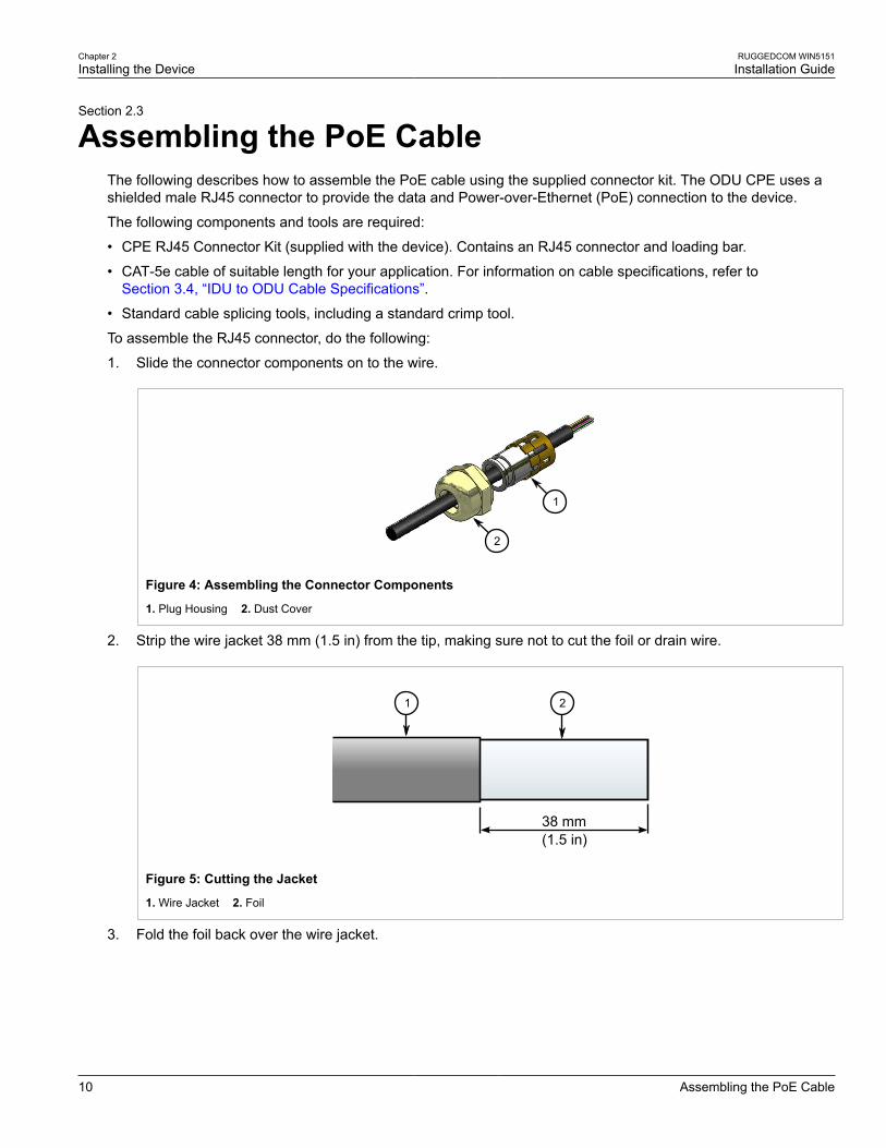
1. Slide the connector components on to the wire.
1
2
Figure 4: Assembling the Connector Components
1. Plug Housing 2. Dust Cover
2. Strip the wire jacket 38 mm (1.5 in) from the tip, making sure not to cut the foil or drain wire.
38 mm(1.5 in)
1 2
Figure 5: Cutting the Jacket
1. Wire Jacket 2. Foil
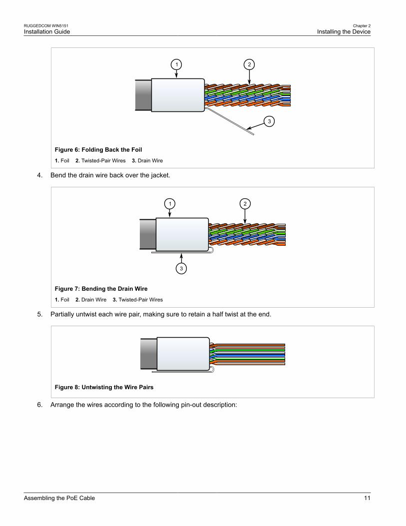
3. Fold the foil back over the wire jacket.
RUGGEDCOM WIN5151Installation Guide
Chapter 2Installing the Device
Assembling the PoE Cable 11
1 2
3
Figure 6: Folding Back the Foil
1. Foil 2. Twisted-Pair Wires 3. Drain Wire
4. Bend the drain wire back over the jacket.
3
1 2
Figure 7: Bending the Drain Wire
1. Foil 2. Drain Wire 3. Twisted-Pair Wires
5. Partially untwist each wire pair, making sure to retain a half twist at the end.
Figure 8: Untwisting the Wire Pairs
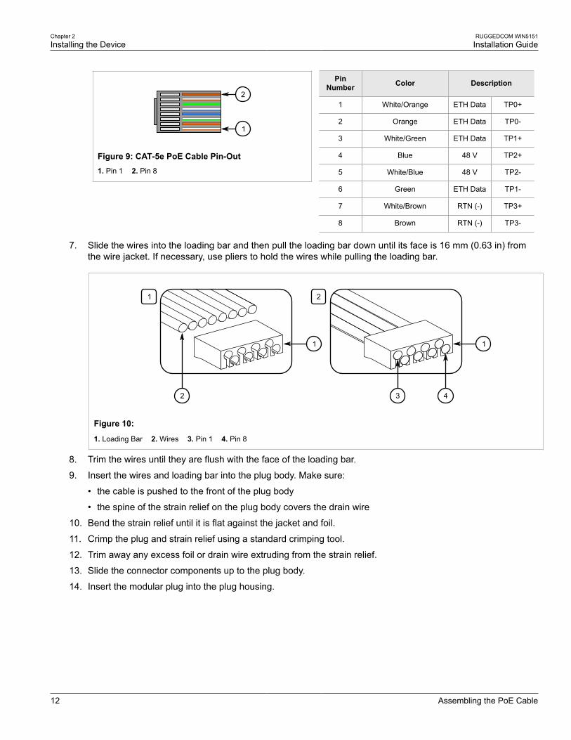
6. Arrange the wires according to the following pin-out description:
Chapter 2Installing the Device
RUGGEDCOM WIN5151Installation Guide
12 Assembling the PoE Cable
1
2
Figure 9: CAT-5e PoE Cable Pin-Out1. Pin 1 2. Pin 8
PinNumber Color Description
1 White/Orange ETH Data TP0+
2 Orange ETH Data TP0-
3 White/Green ETH Data TP1+
4 Blue 48 V TP2+
5 White/Blue 48 V TP2-
6 Green ETH Data TP1-
7 White/Brown RTN (-) TP3+
8 Brown RTN (-) TP3-
7. Slide the wires into the loading bar and then pull the loading bar down until its face is 16 mm (0.63 in) fromthe wire jacket. If necessary, use pliers to hold the wires while pulling the loading bar.
1 2
2
1 1
3 4
Figure 10:
1. Loading Bar 2. Wires 3. Pin 1 4. Pin 8
8. Trim the wires until they are flush with the face of the loading bar.
9. Insert the wires and loading bar into the plug body. Make sure:
• the cable is pushed to the front of the plug body
• the spine of the strain relief on the plug body covers the drain wire
10. Bend the strain relief until it is flat against the jacket and foil.
11. Crimp the plug and strain relief using a standard crimping tool.
12. Trim away any excess foil or drain wire extruding from the strain relief.
13. Slide the connector components up to the plug body.
14. Insert the modular plug into the plug housing.
RUGGEDCOM WIN5151Installation Guide
Chapter 2Installing the Device
Connecting the WIN1010 Data Adapter 13
2
3
1
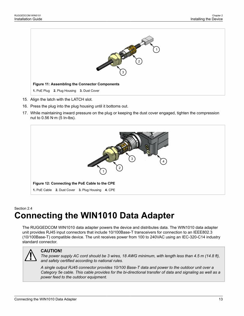
Figure 11: Assembling the Connector Components
1. PoE Plug 2. Plug Housing 3. Dust Cover
15. Align the latch with the LATCH slot.
16. Press the plug into the plug housing until it bottoms out.
17. While maintaining inward pressure on the plug or keeping the dust cover engaged, tighten the compressionnut to 0.56 N·m (5 In-lbs).
4
2
3
1
Figure 12: Connecting the PoE Cable to the CPE
1. PoE Cable 2. Dust Cover 3. Plug Housing 4. CPE
Section 2.4
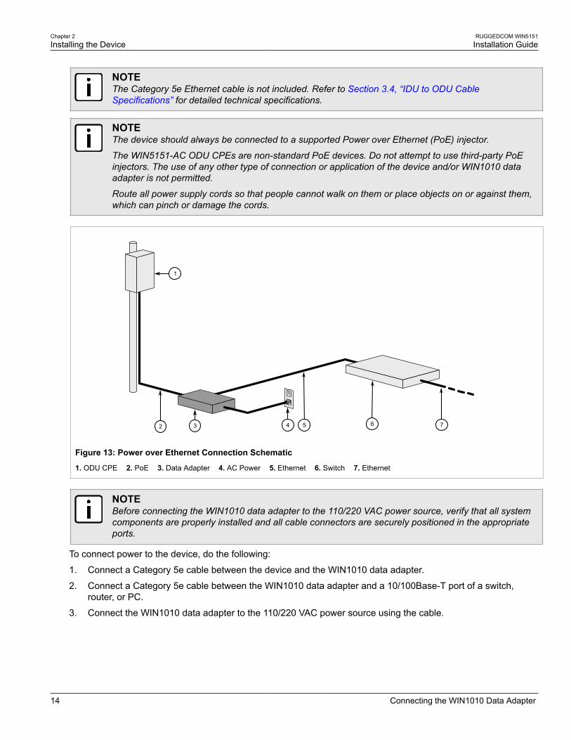
Connecting the WIN1010 Data AdapterThe RUGGEDCOM WIN1010 data adapter powers the device and distributes data. The WIN1010 data adapterunit provides RJ45 input connectors that include 10/100Base-T transceivers for connection to an IEEE802.3(10/100Base-T) compatible device. The unit receives power from 100 to 240VAC using an IEC-320-C14 industrystandard connector.
CAUTION!The power supply AC cord should be 3 wires, 18 AWG minimum, with length less than 4.5 m (14.8 ft),and safety certified according to national rules.
A single output RJ45 connector provides 10/100 Base-T data and power to the outdoor unit over aCategory 5e cable. This cable provides for the bi-directional transfer of data and signaling as well as apower feed to the outdoor equipment.
Chapter 2Installing the Device
RUGGEDCOM WIN5151Installation Guide
14 Connecting the WIN1010 Data Adapter
NOTEThe Category 5e Ethernet cable is not included. Refer to Section 3.4, “IDU to ODU CableSpecifications” for detailed technical specifications.
NOTEThe device should always be connected to a supported Power over Ethernet (PoE) injector.
The WIN5151-AC ODU CPEs are non-standard PoE devices. Do not attempt to use third-party PoEinjectors. The use of any other type of connection or application of the device and/or WIN1010 dataadapter is not permitted.
Route all power supply cords so that people cannot walk on them or place objects on or against them,which can pinch or damage the cords.
32 64 7
1
5
Figure 13: Power over Ethernet Connection Schematic
1. ODU CPE 2. PoE 3. Data Adapter 4. AC Power 5. Ethernet 6. Switch 7. Ethernet
NOTEBefore connecting the WIN1010 data adapter to the 110/220 VAC power source, verify that all systemcomponents are properly installed and all cable connectors are securely positioned in the appropriateports.
To connect power to the device, do the following:
1. Connect a Category 5e cable between the device and the WIN1010 data adapter.
2. Connect a Category 5e cable between the WIN1010 data adapter and a 10/100Base-T port of a switch,router, or PC.
3. Connect the WIN1010 data adapter to the 110/220 VAC power source using the cable.
RUGGEDCOM WIN5151Installation Guide
Chapter 2Installing the Device
Connecting to a RUGGEDCOM RP100 or RP110 15
Section 2.5
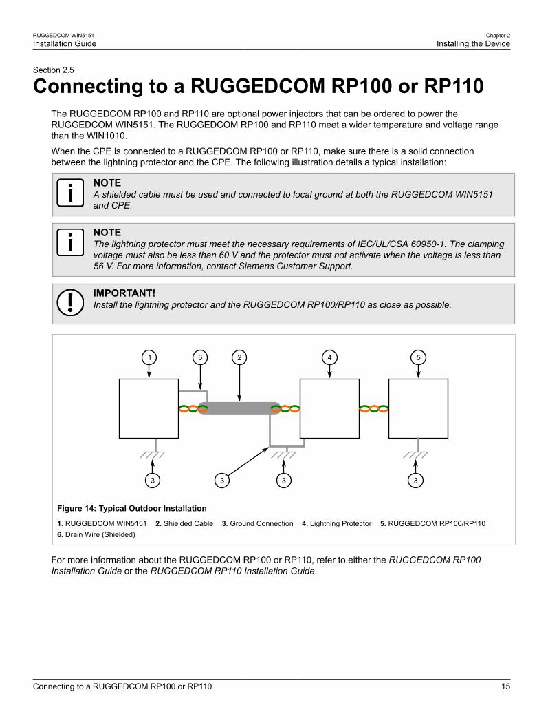
Connecting to a RUGGEDCOM RP100 or RP110The RUGGEDCOM RP100 and RP110 are optional power injectors that can be ordered to power theRUGGEDCOM WIN5151. The RUGGEDCOM RP100 and RP110 meet a wider temperature and voltage rangethan the WIN1010.
When the CPE is connected to a RUGGEDCOM RP100 or RP110, make sure there is a solid connectionbetween the lightning protector and the CPE. The following illustration details a typical installation:
NOTEA shielded cable must be used and connected to local ground at both the RUGGEDCOM WIN5151and CPE.
NOTEThe lightning protector must meet the necessary requirements of IEC/UL/CSA 60950-1. The clampingvoltage must also be less than 60 V and the protector must not activate when the voltage is less than56 V. For more information, contact Siemens Customer Support.
IMPORTANT!Install the lightning protector and the RUGGEDCOM RP100/RP110 as close as possible.
1
3 3 3
4 526
3
Figure 14: Typical Outdoor Installation
1. RUGGEDCOM WIN5151 2. Shielded Cable 3. Ground Connection 4. Lightning Protector 5. RUGGEDCOM RP100/RP110 6. Drain Wire (Shielded)
For more information about the RUGGEDCOM RP100 or RP110, refer to either the RUGGEDCOM RP100Installation Guide or the RUGGEDCOM RP110 Installation Guide.
Chapter 2Installing the Device
RUGGEDCOM WIN5151Installation Guide
16 Installing the Device in Hazardous Locations
Section 2.6
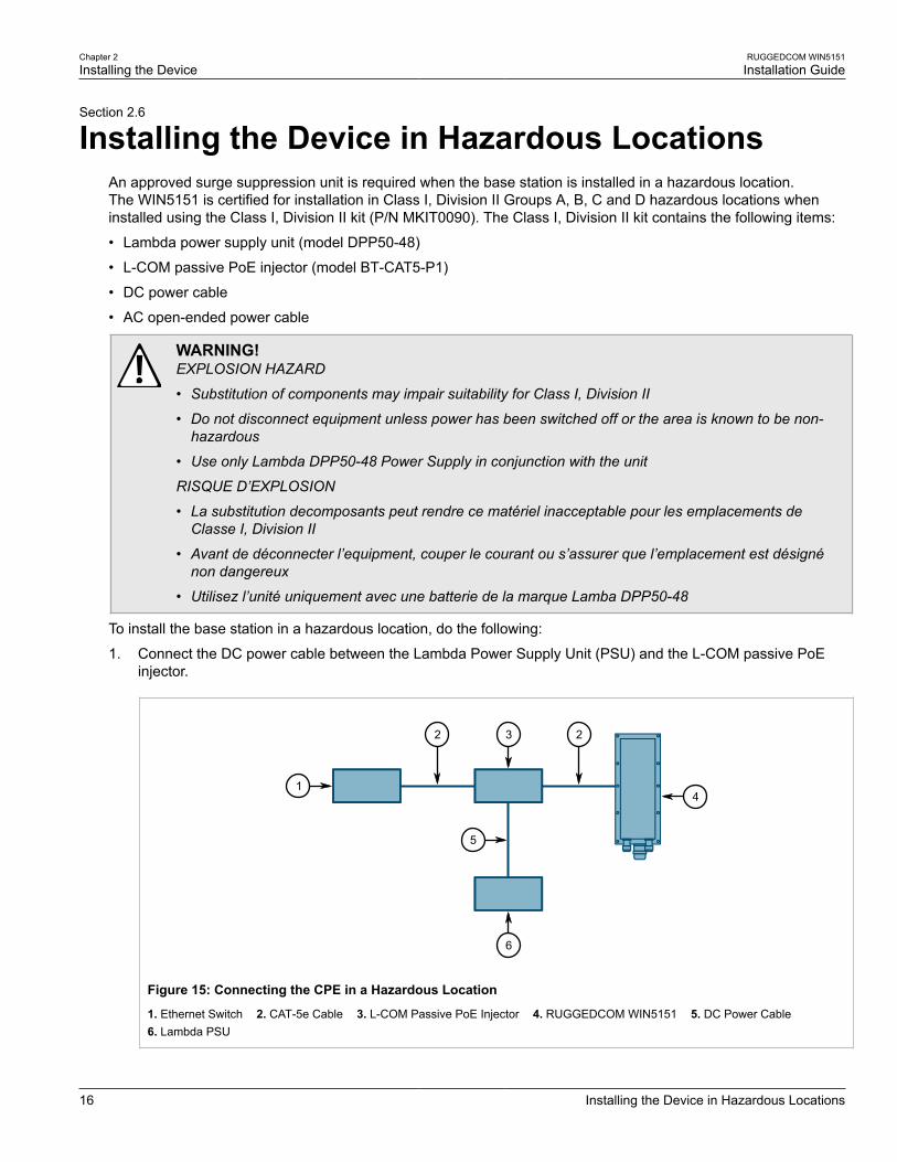
Installing the Device in Hazardous LocationsAn approved surge suppression unit is required when the base station is installed in a hazardous location.The WIN5151 is certified for installation in Class I, Division II Groups A, B, C and D hazardous locations wheninstalled using the Class I, Division II kit (P/N MKIT0090). The Class I, Division II kit contains the following items:
• Lambda power supply unit (model DPP50-48)
• L-COM passive PoE injector (model BT-CAT5-P1)
• DC power cable
• AC open-ended power cable
WARNING!EXPLOSION HAZARD
• Substitution of components may impair suitability for Class I, Division II
• Do not disconnect equipment unless power has been switched off or the area is known to be non-hazardous
• Use only Lambda DPP50-48 Power Supply in conjunction with the unit
RISQUE D’EXPLOSION
• La substitution decomposants peut rendre ce matériel inacceptable pour les emplacements deClasse I, Division II
• Avant de déconnecter l’equipment, couper le courant ou s’assurer que l’emplacement est désignénon dangereux
• Utilisez l’unité uniquement avec une batterie de la marque Lamba DPP50-48
To install the base station in a hazardous location, do the following:
1. Connect the DC power cable between the Lambda Power Supply Unit (PSU) and the L-COM passive PoEinjector.
41
6
2 23
5
Figure 15: Connecting the CPE in a Hazardous Location
1. Ethernet Switch 2. CAT-5e Cable 3. L-COM Passive PoE Injector 4. RUGGEDCOM WIN5151 5. DC Power Cable 6. Lambda PSU
RUGGEDCOM WIN5151Installation Guide
Chapter 2Installing the Device
Grounding the Device 17
2. Using a CAT-5e cable, connect the PoE injector to the CPE.
3. Using a CAT-5e cable, connect the Ethernet switch to the PoE injector.
CAUTION!The AC power cable must consist of 3 wires, be minimum 18 AWG, be less than 4.5 m (14.7 ft)long, and be safety certified according to national rules.
4. Connect the AC open-ended power cable to the Lambda PSU.
Section 2.7
Grounding the DeviceWhen connecting the ground cable to the device, make sure to use a 10 AWG grounding cable and torque thescrew to 15 N·m (11 ft. lb.).
DANGER!Electrocution hazard – risk of death or serious injury. The system must be properly grounded to protectagainst power surges and accumulated static electricity. It is the installer’s responsibility to install thisbase station in accordance with the local electrical codes.
Section 2.8
Weatherproofing the DeviceMost outdoor CPE, antenna or cable problems are caused by coaxial cable connections loosened by vibration,allowing moisture to penetrate the connector interface. Siemens strongly recommends weatherproofing alloutdoor cable connections to prevent the ingress of water and help secure connections.
Since PoE cables also carry DC current, the need for proper weatherproofing cannot be overstated.
Use electrical tape and a heavy-duty weather, abrasion and UV-resistant rubber splicing or self-amalgamatingtape to seal connections.
IMPORTANT!The warranty is void if the base station is assembled without waterproof sealing or if the sealing isremoved from the connections.
IMPORTANT!PVC tape, silicon seal and glue are not recommended for weatherproofing, as these materials aredifficult to apply accurately and are difficult to remove.
IMPORTANT!This method of weatherproofing must be completed on all external connections. If surge arrestors areused, all associated connections and arrestors must be completely wrapped with splicing tape or self-amalgamating tape.
Rubber mastic or duct sealing putty must also be used to complete the weatherproofing where needed.
To weatherproof an outdoor cable connection, do the following for both ends of the cable:
1. Make sure the connector and cable are free of any foreign substances, such as oil, grease or dirt.
Chapter 2Installing the Device
RUGGEDCOM WIN5151Installation Guide
18 Weatherproofing the Device
2. Make sure the connection is secure and the cable extends below the connector to provide a path for water toflow away from the base station.
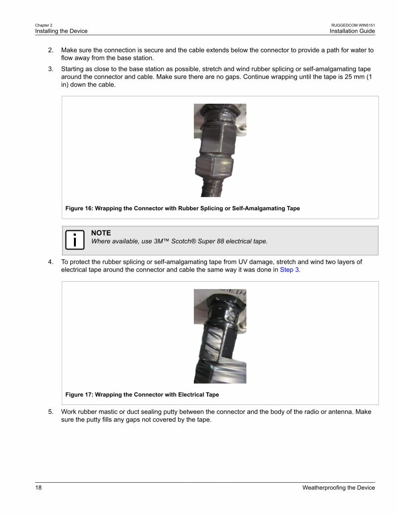
3. Starting as close to the base station as possible, stretch and wind rubber splicing or self-amalgamating tapearound the connector and cable. Make sure there are no gaps. Continue wrapping until the tape is 25 mm (1in) down the cable.
Figure 16: Wrapping the Connector with Rubber Splicing or Self-Amalgamating Tape
NOTEWhere available, use 3M™ Scotch® Super 88 electrical tape.
4. To protect the rubber splicing or self-amalgamating tape from UV damage, stretch and wind two layers ofelectrical tape around the connector and cable the same way it was done in Step 3.
Figure 17: Wrapping the Connector with Electrical Tape
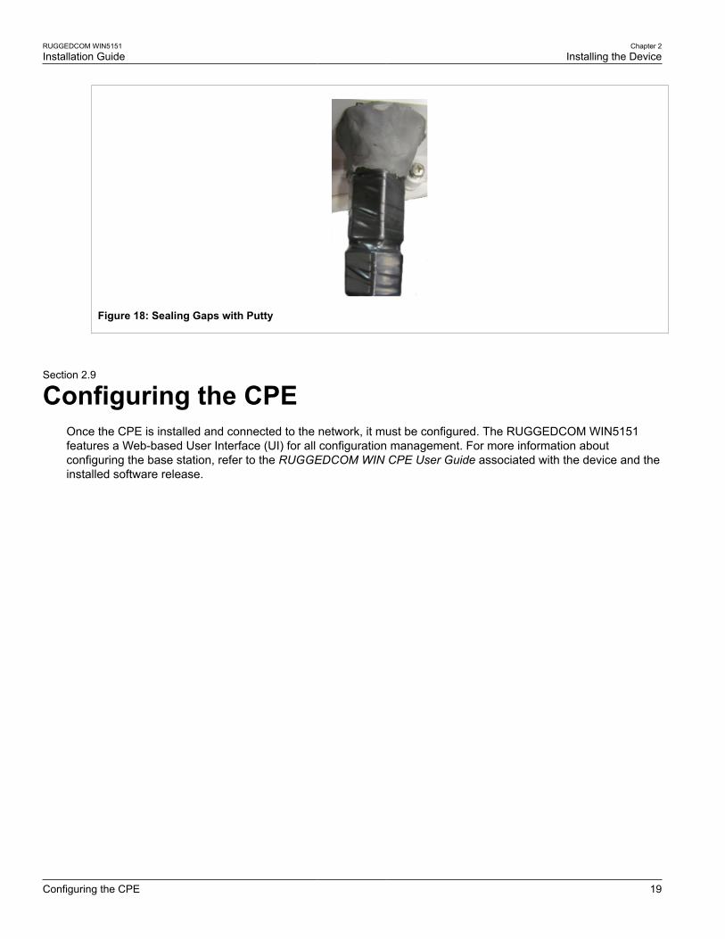
5. Work rubber mastic or duct sealing putty between the connector and the body of the radio or antenna. Makesure the putty fills any gaps not covered by the tape.
RUGGEDCOM WIN5151Installation Guide
Chapter 2Installing the Device
Configuring the CPE 19
Figure 18: Sealing Gaps with Putty
Section 2.9
Configuring the CPEOnce the CPE is installed and connected to the network, it must be configured. The RUGGEDCOM WIN5151features a Web-based User Interface (UI) for all configuration management. For more information aboutconfiguring the base station, refer to the RUGGEDCOM WIN CPE User Guide associated with the device and theinstalled software release.

RUGGEDCOM WIN5151Installation Guide
Chapter 2Installing the Device
Configuring the CPE 20

RUGGEDCOM WIN5151Installation Guide
Chapter 3Technical Specifications
Power Consumption 21
Technical SpecificationsThe following sections provide important technical specifications related to the device:
• Section 3.1, “Power Consumption”
• Section 3.2, “Operating Environment”
• Section 3.3, “Mechanical Specifications”
• Section 3.4, “IDU to ODU Cable Specifications”
Section 3.1
Power ConsumptionTypical power consumption: 12 W
Section 3.2
Operating EnvironmentParameter Range Comments
Ambient Operating Temperature -40 to 75 °C(-40 to 167 °F)
Ambient Relative Humidity 5% to 95% Non-condensing
Ambient Storage Temperature -40 to 75 °C(-40 to 167 °F)
Section 3.3
Mechanical SpecificationsParameter Value
Dimensions Refer to Chapter 4, Dimension Drawings
Weight 1.5 kg (3.3 lb)
Enclosure Aluminum
Ingress Protection IP67
Chapter 3Technical Specifications
RUGGEDCOM WIN5151Installation Guide
22 IDU to ODU Cable Specifications
Section 3.4
IDU to ODU Cable SpecificationsSpecial 4×2×24 AWG FTP Cat. 5e Outdoor Double Jacket Data Cable UL (1581 VW 1)
IDU to ODU CableApplications: Outdoor installations, fixed or portable installations, digital distribution frames in
transmission stations, outdoor installations in harsh environments.
General Construction: Custom made cable designed specially for wireless systems, meeting the requirements ofCat. 5e per ANSI/TIA/EIA-568-B.2 and IEC 61156-5. The cable contains 4 twisted pairs,cabled, foil-tape shielded and jacketed with two special black UV resistant, flame retardantPVC compounds for direct outdoor use in harsh electrical environments. The diameter of theinner core complies with RJ45 connecting hardware allowing direct connection to equipmentwithout patch cords.
Conductor Size: 0.52 mm
Outer Jacket Material: UV resistant FR-PVC
Outer Diameter: 7.9 mm nominal
Weight: 68.0 kg/km
IDU to ODU Cable Design and MaterialsConductor Material: Bare copper
Conductor Size: 24 AWG
Insulation Material: Solid PO
Insulation O.D.: 1.07 mm
Color Code: Per TIA/EIA 568-B
Overall Foil Shield: Yes
Overall Shield Material: Aluminum/Polyester Foil
Overall Foil Design: 100% Coverage
Overall Drain-wire Material: Tinned Copper
Overall Drain-wire Size: 24 AWG
Overall Drain-wire Construction: Stranded
Inner Jacket Material: UV resistant FR-PVC
Inner Jacket Diameter: 6.1 mm
Total Number of Wires: 8
IDU to ODU Cable StandardsFlammability Rating: IEC 60332, UL1581 VW-1
Standards: IEC 61156, TIA/EIA-568
IDU to ODU Cable PerformanceFrequency Range: 1-100 MHz

RUGGEDCOM WIN5151Installation Guide
Chapter 3Technical Specifications
IDU to ODU Cable Specifications 23
Impedance: 100 Ω
DC Resistance: 93 Ω/km nominal
Max. DC Resistance 95 Ω/km @ 20 °C
Capacitance Unbalance: 1.6 pF/m maximum
Velocity of Propagation: 68% nominal
Propagation Delay Skew: 35 ns/100 m maximum
Dielectric Strength: 700 V/minute
Dielectric Strength to Shield: 700 V/minute
Minimum Bend Radius: 70 mm
Operating Temperature Range: -40 to 70 °C

RUGGEDCOM WIN5151Installation Guide
Chapter 3Technical Specifications
IDU to ODU Cable Specifications 24

RUGGEDCOM WIN5151Installation Guide
Chapter 4Dimension Drawings
25
Dimension DrawingsNOTEAll dimensions are in millimeters, unless otherwise stated.

RUGGEDCOM WIN5151Installation Guide
Chapter 4Dimension Drawings
26

RUGGEDCOM WIN5151Installation Guide
Chapter 5Certification
Standards Compliance 27
CertificationThe RUGGEDCOM WIN5151 ODU CPE has been thoroughly tested to guarantee its conformance withrecognized standards and has received approval from recognized regulatory agencies.
• Section 5.1, “Standards Compliance”
• Section 5.2, “Agency Approvals”
• Section 5.3, “MIL-STD Ratings”
• Section 5.4, “IEEE 802.16e Mobile WiMAX Compliance”
• Section 5.5, “Environmental Type Tests”
Section 5.1
Standards ComplianceThe RUGGEDCOM WIN5151 complies with the following standards:
• FCC ComplianceThis equipment has been tested and found to comply with the limits for a Class A digital device pursuantto Part 15 of the FCC Rules. These limits are designed to provide reasonable protection against harmfulinterference when the equipment is operated in a commercial environment.
This equipment generates, uses and can radiate radio frequency energy and, if not installed and used inaccordance with the instruction manual, may cause harmful interference to radio communications. Operationof this equipment in a residential area is likely to cause harmful interference in which case the user will berequired to correct the interference on his own expense.
• Industry Canada ComplianceCAN ICES-3 (A) / NMB-3 (A)
• OtherEN 50155 (Railway)
Section 5.2
Agency ApprovalsThe RUGGEDCOM WIN5151 has received approval from various agencies.
Agency Standards Comments
CSA CSA C22 Approved
CE EN 60950-1 Approved
TUV UL 60950-1 Approved
CE ETSI EN 301489-1/4,ETSI EN 302 326-1/2/3
Approved
Chapter 5Certification
RUGGEDCOM WIN5151Installation Guide
28 MIL-STD Ratings
Agency Standards Comments
ETSI ETS 300 019 Approved
UL/CSA Class I Div II, UL 1604,CSA 22.2 No213-M1987
Approved
ATEX Zone 2 EN60079-0, EN60079-15 Approved
Section 5.3
MIL-STD RatingsTest Description Test Levels
IEC 60068-2-11
MIL-STD-810E
SALT FOG 5% NaCI 35° 48h
Section 5.4
IEEE 802.16e Mobile WiMAX ComplianceThe IEEE802.16-2005 specifications describe a Point-to-Multipoint (PMP) broadband wireless access standardfor systems. This standard includes descriptions for both the Media Access Control (MAC) and the physical(PHY) layers.
The device is compliant to the IEEE802.16-2005 WiMAX forum Wave 2 profile.
NOTEThe RUGGEDCOM WIN1010 WIN product family is designed to comply with a specific revision of theIEEE 802.16e standards, which are subject to amendment.
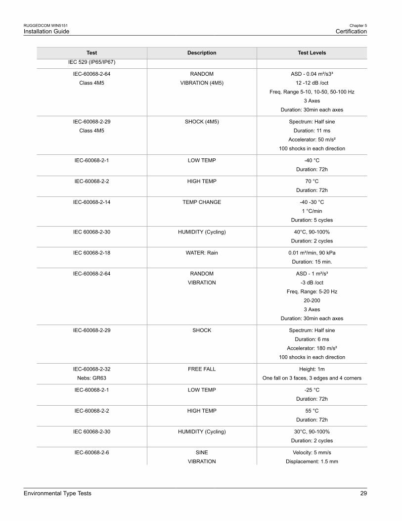
Section 5.5
Environmental Type TestsTest Description Test Levels
IEC-60068-2-1 LOW TEMP -40 °C
Duration: 16h
IEC-60068-2-2 HIGH TEMP 60 °C
Duration: 16h
IEC-60068-2-14 TEMP CHANGE -10 to 45 °C
0.5 °C/min
Duration: 2 cycles
IEC 60068-2-30 HUMIDITY (Cycling) 30°C 90-100%
Duration: 2 cycles
IEC 60068-2-18 WATER: Rain (intensity) 0.01m3/min, 90kPa, 30min
RUGGEDCOM WIN5151Installation Guide
Chapter 5Certification
Environmental Type Tests 29
Test Description Test Levels
IEC 529 (IP65/IP67)
IEC-60068-2-64
Class 4M5
RANDOM
VIBRATION (4M5)
ASD - 0.04 m²/s3³
12 -12 dB /oct
Freq. Range 5-10, 10-50, 50-100 Hz
3 Axes
Duration: 30min each axes
IEC-60068-2-29
Class 4M5
SHOCK (4M5) Spectrum: Half sine
Duration: 11 ms
Accelerator: 50 m/s²
100 shocks in each direction
IEC-60068-2-1 LOW TEMP -40 °C
Duration: 72h
IEC-60068-2-2 HIGH TEMP 70 °C
Duration: 72h
IEC-60068-2-14 TEMP CHANGE -40 -30 °C
1 °C/min
Duration: 5 cycles
IEC 60068-2-30 HUMIDITY (Cycling) 40°C, 90-100%
Duration: 2 cycles
IEC 60068-2-18 WATER: Rain 0.01 m³/min, 90 kPa
Duration: 15 min.
IEC-60068-2-64 RANDOM
VIBRATION
ASD - 1 m²/s³
-3 dB /oct
Freq. Range: 5-20 Hz
20-200
3 Axes
Duration: 30min each axes
IEC-60068-2-29 SHOCK Spectrum: Half sine
Duration: 6 ms
Accelerator: 180 m/s²
100 shocks in each direction
IEC-60068-2-32
Nebs: GR63
FREE FALL Height: 1m
One fall on 3 faces, 3 edges and 4 corners
IEC-60068-2-1 LOW TEMP -25 °C
Duration: 72h
IEC-60068-2-2 HIGH TEMP 55 °C
Duration: 72h
IEC 60068-2-30 HUMIDITY (Cycling) 30°C, 90-100%
Duration: 2 cycles
IEC-60068-2-6 SINE
VIBRATION
Velocity: 5 mm/s
Displacement: 1.5 mm

Chapter 5Certification
RUGGEDCOM WIN5151Installation Guide
30 Environmental Type Tests
Test Description Test Levels
Acceleration: 2 m/s²
Frequency Range: 5-62, 62-200 Hz
3 Axes
Duration: 3x5 sweep