RUCKER LANDING SUBDIVISIONrcsharepoint.rutherfordcountytn.gov/sites/Commission...2018/05/29 ·...
16
RUCKER LANDING SUBDIVISION REGULATING PATTERN BOOK DEVELOPER LandQuestor, LLC Attn: Larry Gilliland P.O.Box 463 Murfreesboro, TN 37133 ENGINEER ATTN: LINDA SULLIVAN, PE 307 HICKERSON DRIVE MUFREESBORO, TN 37129 (615) 663-7678 www.cia-engineers.com A PROPERTY REZONING REQUEST FROM R.M. TO P.U.D. Rucker Landing is a P.U.D. concept plan of all residential single family dwellings located on lots of at least 7200 square feet. The plan consists of 7 Estate lots and 230 Standard lots. The plan hosts an overall density of 2.41 units/acre. This project lies within the Suburban Belt Character. The Rucker Landing Concept supports this density. All of the homes in the Approved P.U.D. will have provided for 3 or more bedrooms. Each dwelling unit will be for purchase. The plan also incorporates an amenities program, which includes a playground and large usable open space, which will be included in a professionally managed Home Owners’ Association (HOA).
Transcript of RUCKER LANDING SUBDIVISIONrcsharepoint.rutherfordcountytn.gov/sites/Commission...2018/05/29 ·...

RUCKER LANDING SUBDIVISIONREGULATING PATTERN BOOK
DEVELOPER
LandQuestor, LLCAttn: Larry GillilandP.O.Box 463Murfreesboro, TN 37133
ENGINEER
ATTN: LINDA SULLIVAN, PE307 HICKERSON DRIVEMUFREESBORO, TN 37129(615) 663-7678www.cia-engineers.com
A PROPERTY REZONING REQUEST FROM R.M. TO P.U.D.
Rucker Landing is a P.U.D. concept plan of all residential single family dwellings located on lots of at least 7200 square feet.
The plan consists of 7 Estate lots and 230 Standard lots.
The plan hosts an overall density of 2.41 units/acre.
This project lies within the Suburban Belt Character. The Rucker Landing Concept supports this density.
All of the homes in the Approved P.U.D. will have provided for 3 or more bedrooms.
Each dwelling unit will be for purchase.
The plan also incorporates an amenities program, which includes a playground and large usable open space, which will be included in a professionally managed Home Owners’ Association (HOA).

TABLE OF CONTENTS
PROJECT OVERVIEWAERIAL / ZONING
TOPOGRAPHY AND DRAINAGE
SOILS
ON-SITE PHOTOS
PROJECT PLANP.U.D. CONCEPT
RIGHT-OF-WAY CONNECTIONS
PHASING PLAN
UTILITY CONNECTIONS
DECENTRALIZED ON-SITE SANITARY SEWAGE SYSTEM
PROPOSED HOME OPTIONS
AMENITIES
. . . . . . . . . . . . . . . . . . . . . . . . .. . . . . . . . . . . . . . . . . . . .. . . . . . . . . . . . . . . . . . . . . . . . . . . . . . . . . . . . . . . . . 3
. . . . . . . . . . . . . . . . . . . . . . . . .. . . . . . . . . . . . . . . . . . . .. . . . . . . . . . . . . . . . . . . . . . . . . . . . . . . . . . . . . . . . . 4
. . . . . . . . . . . . . . . . . . . . . . . . .. . . . . . . . . . . . . . . . . . . .. . . . . . . . . . . . . . . . . . . . . . . . . . . . . . . . . . . . . . . . . 6
. . . . . . . . . . . . . . . . . . . . . . . . . . . . . . . . . . . . . . . . . . . . . . . . . . . . . . . . . . . . . . . . . . . . . . . . . . . . . . . . . . . . . 7
. . . . . . . . . . . . . . . . . . . . . . . . . . . . . . . . . . . . . . . . . . . . . . . . . . . . . . . . . . . .. . . . . . . . . . . . . . . . . . . . . . . . . .8
. . . . . . . . . . . . . . . . . . . . . . . . . . . . . . . . . . . . . . . . . . . . . . . . . . . . . . . . . . . . . . . . . .. . . . . . . . . . . . . . . . . . . 9
. . . . . . . . . . . . . . . . . . . . . . . . . . . . . . . . . . . . . . . . . . . . . . . . . . . . . . . . . . . . . . . . . . . . . . . . . . . . . . . . . . . .11
. . . . . . . . . . . . . . . . . . . . . . . . . . . . . . . . . . . . . . . . . . . . . . . . . . . . . . . . . . . .. . . . . . . . . . . . . . . . . . . . . . . . 12
. . . . . . . . . . . . . . . . . . . . . . . . . . . . . . . . . . . . . . . . . . . . . . . . . . . . . . . . . . . . . . . . . . .13
. . . . . . . . . . . . . . . . . . . . . . . . . . . . . . . . . . . . . . . . . . . . . . . . . . . . . . . . . . . . . . . . . . . . . . . . . . . . . . . . . . . . 14
. . . . . . . . . . . . . . . . . . . . . . . . . . . . . . . . . . . . . . . . . . . . . . . . . . . . . . . . . . . . . . . . . . . . . . . . . . . . . . . . . . . . 17
PAGE | 2

PROJECT OVERVIEW
Party respectively requests to rezone the Rucker Road property from R.M. to P.U.D.
The area to be rezoned is approximately 99 acres and is shown as a portion of parcel 008.01 on Rutherford County Tax Map 149.
Current zoning for the subject parcel is RM (Residential Medium Density).
All surrounding properties are zoned RM –Rutherford County Zoning Map
AERIAL / ZONING / UTILITIES
EXHIBIT
AERIAL / ZONING
RM
RM
RM
RMRM
RM
RM
RM
RM
PAGE | 3

The existing topography of the site shows storm water drainage is approximately Southwest to Northeast and in general, flows West to East.
Storm water runoff from the entire site feeds into a 24” R.C.P. under the CSX Railroad and enters Long Creek (TDEC TN0513023021_0300) from the Northeast corner of the property.
Preliminary drainage area = 124.6 Acres± or 5,428,352.03 S.F.±
TOPOGRAPHY AND DRAINAGE
PROJECT OVERVIEW
PAGE | 4

TOPOGRAPHY AND DRAINAGE (cont’d)
PROJECT OVERVIEW
PAGE | 5
Curb, gutter, inlet, and pipe system to detention pond.
System consists of pretreatment, dry detention, and wet pond,all to achieve 80% TSS removal.
Due to the extremely flat nature of the site, the pretreatmentsystem will require detailed design.
The site requires a wet extended detention pond.
The wet pond storage will have the required access bench,aquatic bench, liner, and landscaping.
Permanent vehicle access to all components of the pondsystem will be included in the design and will be included in adrainage easement.
The outlet structure will require detailed design related toaccommodating the entire drainage area and the limitedcapacity of the existing 24 inch concrete pipe under the CSXRailroad. An emergency spillway will also be provided.
It has also been noted that some of the finished floorelevations will be required to be 1 foot above the lowest basinoutlet on the site.
Downstream impacts will be considered for the 2 through 100year storm events.
The emergency spillway will be designed for the 100 yearstorm event and for instances of clogging of the primary outletstructure (24 inch railroad culvert).
All county requirements will be followed regarding easements,as-builts, and operation and maintenance agreements.
Collection:
Detention:
Outlet:
Operation and Maintenance:
STORMWATER MANAGEMENT SYSTEM
NOTE: A temporary access road for vehicle traffic will beinstalled and maintained between phases until the permanentaccess is complete.

The existing soils shown were derived from USDA NCRA Soils Classification Map.
The suitable soils for the Decentralized On-Site Sanitary Sewage Treatment System are Lomond Silt (LoA) and Harpeth Silt Loam (HcA). The majority soils are concentrated on the West side of the property. This was taken into consideration for the proposed plan.
A current field study and soils grid has been performed by the Soils Group and the results are reflected in the Preliminary Drainage Study and the soils area to be reserved for the Decentralized On-Site Sanitary Sewage Treatment System.
SOILS
PROJECT OVERVIEW
PAGE | 6

ON-SITE PHOTOS
PROJECT OVERVIEW
From future Drema Court at the South boundary line looking North.
At the East boundary line, looking East at the 24” R.C.P. under the CSX Railroad.
At the dead end of Jonathan Way looking East.
At the Northwest property corner looking East down Rucker Road.
At the Northern property line on Rucker Road looking Southeast.
Just South of Rucker Road looking North across Rucker Road.
PAGE | 7

Land Use Data:
Approximate Total Land Area:
Total Number of Lots: Gross Density:
Minimum Typical Interior Lot Size:
Typical Lot Width at Setback:.
Approximate Total Open Space:
Required Open Space (10%):Required Usable Open Space (5%):Storm Water (Not Usable):
Provided Usable Open Space:
Decentralized Sanitary SewerTreatment System Area:
Total Soils Provided:Primary Soil Area:Reserve Soil Area:
P.U.D. CONCEPT
PROJECT PLAN
PAGE | 8
Minimum Interior Lot
Minimum Corner Lot
98.33 Acres
237 Lots
237 lots / 98.33 Acres = 2.41 Units/ Acre
60 ft. x 120 ft. (7200 S.F.)
60 ft.
12.97 Acres
8.00 Acres4.00 Acres0.61 Acres
11.76 Acres
18.32 Acres
12.14 Acres9.62 Acres2.52 Acres

All streets will be public right-of-way.
The Main Entrance off of Rucker Road will have an entrance sign constructed of masonry materials surrounded by landscaping.
All streets have been designed to comply with the Rutherford County’s Subdivision Regulations.
There will be no connection to Jonathan Way in Applewood Section 2.
An internal street connection to Drema Court will tie into Colonial Estates Section 12 Phase 3B.
A future internal street connector is planned West of Drema Court on the South line of Rucker Landing.
The developer is committed to the recommendations listed in the traffic study for the improvement of the intersection at US HWY 231 and Rucker Road (Traffic Impact Study, Rucker Landing Rucker Road Rutherford County, TN, prepared March 2018 by Fischbach Transportation Group, LLC). Rucker Landing is working directly with developers of Davenport Station to coordinate the improvements.
RIGHT-OF-WAY CONNECTIONS
PROJECT PLAN
PAGE | 9
RUCKER ROAD CONNECTIONS
DREMA COURT AND FUTURE INTERNAL STREET CONNECTIONS
NO CONNECTION TO JONATHAN WAY
EXAMPLE OF PROPOSED SUBDIVISION SIGNAGE AT THE MAIN ENTRANCE

Davenport Station developer is currently mandated to install intersection improvements at the intersection of Rucker Road and US Hwy 231 to include a traffic signal as identified in the April 2017 Traffic Study for Davenport Station. The Rucker Landing developer is committed to installing their side of the intersection and traffic light improvements as per the 4 (four) recommendations of the Fischbach Transportation Group, LLC traffic study page 37.
1. A separate right turn lane should be provided on Rucker Road at the intersection with US Hwy 231. Should include at least 150 feet of storage and designed according to AASHTO standards.
2. The existing traffic volumes at the intersection of Rucker Road and US Hwy 231 warrant the installation of a traffic signal by the 50th
Certificate of Occupancy issued.3. Each of the project accesses should be
constructed to include one southbound entering lane and one northbound exiting lane, striped as a shard left and right turn lane. (See Rucker Road Connections illustration on Page 8 for access)
4. A four-foot shoulder should be provided on Rucker Road along the frontage of the project site (the South margin of Rucker Road).
RIGHT-OF-WAY CONNECTIONS (cont’d)
PROJECT PLAN
PAGE | 10

Rucker Landing is anticipated to be built in 6 phases.
Construction of Phase 1 is anticipated to start 90 days after rezoning is approved and the process is completed.
Remaining sections construction schedule will be market driven and dependent upon the absorption of the lots in the previous construction phase.
In general, following phases construction will begin after the previous phase is 60% sold.
Phase 1: Primary entrance and signage on Rucker Road, 7 Estate Lots, 41 Standard Lots, and the Decentralized On-Site Sanitary Sewer Treatment System
Phase 2: 38 Standard Lots
Phase 3: 43 Standard Lots
Phase 4: 42 Standard Lots and Playground
Phase 5: 39 Standard Lots
Phase 6: 27 Standard Lots and Secondary entrance on Rucker Road.
PHASING PLAN
PROJECT PLAN
PAGE | 11

PROJECT PLAN
UTILITY CONNECTIONS
Roads: Rutherford County
Power: Middle Tennessee Electric Membership Corporation
Natural Gas: Atmos Energy
Sanitary Sewer: Consolidated Utility Distrcit of Rutherford County
Water:Consolidated Utility DistrictATTN: Bryant Bradley
Project Manager709 New Salem Hwy., P.O. BOX 249Murfreesboro, TN 37133-0249
The Subject Development is proposing connections to the existing waterlines on the North and South of the Development.
One connection is required at the Rucker Landing entrance to the Existing 6 inch P.V.C./SDR 21 that follows the South margin of Rucker Road. Two possible locations exist for this connection at either entrance to Rucker Landing.
An additional waterline connection will be to the 8 inch D.I.P. waterline at the Drema Court Street Connection at the common line of Rucker Landing and Colonial Estates Section 12 Ph. 3b.
THERE WILL BE NO CONNECTION TO THE 6” P.V.C./SDR 21 WATERLINE ON JONATHAN WAY.
UTILITY CONNECTIONS
PAGE | 12

The Decentralized On-Site Sanitary Sewage Treatment System consists of an individual septic tank and effluent pump per dwelling connected to a force main pipe flowing to a recirculated sand filtration and drip field (drip fields annotated as hatched area shown in exhibit to the left).
DECENTRALIZED ON-SITE SANITARY SEWAGE TREATMENT SYSTEM
PROJECT PLAN
TYPICAL RESIDENTIAL SERVICE CONNECTION
DETAIL
PAGE | 13

All home areas will range in size from 2400 + square feet.
All homes will have a 2-car garage.
The homes can be 1,1 ½, or 2 story buildings.
For all of the Estate Lots on Rucker Road, the entire home will be constructed with 70% brick or masonry finish, allowing Hardie-type siding on gable ends and dormers.
All homes will have at least 3 bedrooms.
Estate Lots and the Common Areas will be part of a professionally managed Home Owners Association (HOA).
PROPOSED HOME OPTIONS FOR LOTS FRONTING RUCKER ROAD
PROJECT PLAN
THE ALEXANDRIA THE MADISON II
THE MAGNOLIA
PAGE | 14
ESTATE LOTS

All home areas will range in size from 1600+ square feet.
All homes will have a 2-car garage.
The homes can be 1,1 ½, or 2 story buildings.
Exterior walls facing the Right-of-Way will be constructed with 70% brick & masonry, allowing Hardie-board type materials on gable ends and dormers.
Rear and side elevations will allow 100% siding, brick, masonry, or a combination.
All homes will have at least 3 bedrooms.
Standard Lots and the Common Areas will be part of a professionally managed HOA.
PROJECT PLAN
THE CATHERINE THE EMILY
THE GABRIELLE THE LINDSAY
PAGE | 15
PROPOSED HOME OPTIONS FOR STANDARD LOTS
RUCKER LANDING STANDARD LOTS
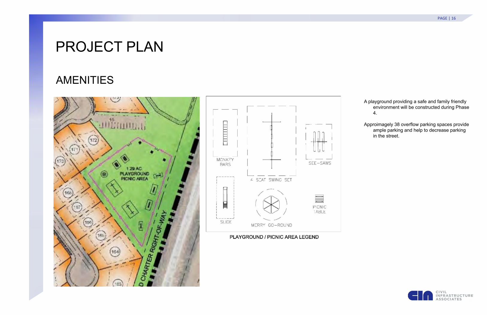
A playground providing a safe and family friendly environment will be constructed during Phase 4.
Approimagely 38 overflow parking spaces provide ample parking and help to decrease parking in the street.
AMENITIES
PROJECT PLAN
PAGE | 16