RTMOTION LCS MK3 - Cloud Object Storage | Store ... ndoln andia balter bilecahalW o.heuvrin pohewte...
40
RTMOTION LCS MK3.1 &LATITUDEMDR LCS(Lens Control System) &Accessory Ecosystem User Guide REVISION: 2016-06-22 (#21) rtmotion.com/knowledge
-
Upload
nguyennhan -
Category
Documents
-
view
217 -
download
2
Transcript of RTMOTION LCS MK3 - Cloud Object Storage | Store ... ndoln andia balter bilecahalW o.heuvrin pohewte...

RTMOTION LCS MK3.1
& LATITUDE MDR
LCS (Lens Control System)& Accessory Ecosystem
User Guide
REVISION: 2016-06-22 (#21)rtmotion.com/knowledge
Lens Control System
1Lens Control SystemTable of Contents1. Lens Control System..........................................................................................................................22. Quick Start Guide – Receiver MK3.1........................................................................................33. Quick Start Guide – LATITUDE...................................................................................................44. System Overview.................................................................................................................................5Theory of Operation................................................................................................................................5Usage Chart – MK3.1..............................................................................................................................7
5. Controller MK3.1...................................................................................................................................86. Receiver MK3.1....................................................................................................................................127. LATITUDE Devices...........................................................................................................................15Standalone LATITUDE-MDR operating modes...............................................................17
8. MK3.1 Motor..........................................................................................................................................209. Slave Controller – Thumbwheel.............................................................................................2210. Smart Knob.........................................................................................................................................2311. Updating Firmwares......................................................................................................................2412. Menu Tree (via Controller)........................................................................................................2813. Technical Reference....................................................................................................................32Compatibility Guidance.....................................................................................................................32Pin-Outs........................................................................................................................................................33Sizes & Weights......................................................................................................................................35
14. Quick Troubleshooting...............................................................................................................3615. Usage and Care...............................................................................................................................38Usage & Environment........................................................................................................................38Accidental Damage.............................................................................................................................38
16. Warranty and Servicing.............................................................................................................3912/24 Month WARRANTY...............................................................................................................39Info & Troubleshooting......................................................................................................................40
2

Quick Start Guide – Receiver MK3.1
2Quick Start Guide – Receiver MK3.1
Initial Setup
1.Plug 12-17V into the RECEIVER's “PWR” port.
The ideal source is a ~14.8V battery (i.e. 4S Lithium cells).
If the voltage is over ~17.5V or polarity is reversed, the RECEIVER will block thedangerous voltage and not start.
2.A=x one or more MOTORS to the rods/lens.
Each motor is factory-set to a certain class (Focus, Iris, Zoom) and labelled accordingly.You can re-assign motor classes via the menu.
3.Plug the MOTOR(s) into the RECEIVER unit.
Plug the Motor(s) into any motor port, the Motors will begin calibrating.
4.Put a Canon LP-E6 battery in the CONTROLLER and hold down thePWR button.
Camera Run/Stop
1.Connect the appropriate Run/Stop cable from the CAM port on theReceiver to your Camera.
2.Enter the Controller’s MENU, Select CAMERA, then select whichcamera you have connected.
3.You can now Run/Stop the camera with the REC button.
3

Quick Start Guide – LATITUDE
3Quick Start Guide – LATITUDE
Initial Setup
1.Plug 12-17V into the “PWR” port.
The ideal source is a ~14.8V battery, such as 4S Lithium cells.
2.A=x MOTOR(s) to the rods/lens.
Each motor is factory-set to a certain class (Focus, Iris, Zoom) and labelled accordingly. You canre-assign motor classes via the menu.
3.Plug the MOTOR(s) into the LATITUDE unit.
Plug the Motor into any motor port, the Motor(s) will begin calibrating.
4.Put a Canon LP-E6 battery in the CONTROLLER and hold down thePWR button.
Camera Run/Stop & EF Lens Control (RED)
1.Connect a CTRL cable between the Camera and Latitude CTRLsockets.
2.Enter the Controller’s MENU, Select CAMERA then RED CTRL.
Camera Run/Stop (non-RED)
1.Connect the appropriate Run/Stop cable from the CTRL port onthe LATITUDE to your Camera.
2.Enter the Controller’s MENU, Select CAMERA, then select whichcamera you have connected.
3.You can now Run/Stop the camera with the REC button.
4
System Overview
4System Overview
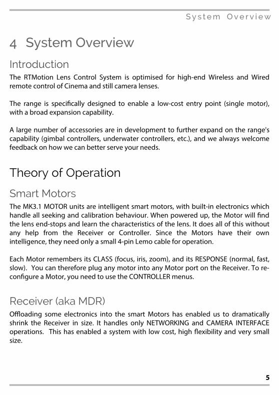
IntroductionThe RTMotion Lens Control System is optimised for high-end Wireless and Wired
remote control of Cinema and still camera lenses.
The range is speci⌧cally designed to enable a low-cost entry point (single motor),
with a broad expansion capability.
A large number of accessories are in development to further expand on the range's
capability (gimbal controllers, underwater controllers, etc.), and we always welcome
feedback on how we can better serve your needs.
Theory of Operation
Smart MotorsThe MK3.1 MOTOR units are intelligent smart motors, with built-in electronics which
handle all seeking and calibration behaviour. When powered up, the Motor will ⌧nd
the lens end-stops and learn the characteristics of the lens. It does all of this without
any help from the Receiver or Controller. Since the Motors have their own
intelligence, they need only a small 4-pin Lemo cable for operation.
Each Motor remembers its CLASS (focus, iris, zoom), and its RESPONSE (normal, fast,
slow). You can therefore plug any motor into any Motor port on the Receiver. To re-
con⌧gure a Motor, you need to use the CONTROLLER menus.
Receiver (aka MDR)O3oading some electronics into the smart Motors has enabled us to dramatically
shrink the Receiver in size. It handles only NETWORKING and CAMERA INTERFACE
operations. This has enabled a system with low cost, high 6exibility and very small
size.
5

System Overview
Controller (Hand Unit)The Controller is the main brain of the unit. Via its OLED screen it also handles the
remote-con⌧guration of the Receiver/MDR and Motors.
LATITUDE MDRThe new LATITUDE range of MDRs (aka receivers) take the heart of the MK3.1 Receiver
and add extensive networking and camera interoperability. Initially the platform will
provide deep integration with RED's o;cial 3rd party programme, including the ability
to drive EF & Nikon lenses via their internal motors, and access to internal RED
parameters. The LATITUDE platform has the power and potential to integrate deeply
with other cameras, systems, motion control platforms, etc. for years to come.
WirelessFrom MK3.1 onwards, devices include our latest RF3-Generation wireless modules.
We strive to stay at the forefront of performance, and are proud to o=er the longest
range, most interference-immune wireless solution on the market. FCC and CE
certi⌧cation is of course retained, and we are now right up to the legal limit.
Slave ControllersSlave Controllers are simple (a=ordable) devices–such as joysticks, thumbwheels,
record buttons–which rely on the electronics inside the Receiver/MDR to function.
To use a Slave Controller, you need to attach it to the AUX or IN-1/ IN-2 port of a
compatible RECEIVER or LATITUDE MDR.
Smart ControllersSmart Controllers contain electronics, and therefore do not require a Controller or
Receiver to function. The ⌧rst Smart Controller in the RTMotion range is the Smart
Knob (see page 23).
6

System Overview
Usage Chart – MK3.1
7

Controller MK3.1
5Controller MK3.1The Controller MK3.1 gives from 4 to 6 axis control.
Note: Picture shows MK3.1/Z variant (with Force-Zoom Joystick).
Variants
MK3.1/S, “Slider”. 4 AXIS CONTROLLarge Focus Knob + Slider + 2x Side Knobs (A/B).
MK3.1/Z, “Force-Zoom”. 6 AXIS CONTROLLarge Focus Knob + Slider + 2x Side Knobs (A/B) + Force Joystick (X/Y).
8

Controller MK3.1
Con>gurationsAny INPUT (Large knob, Side Knob A, etc.) can be assigned to any LENS AXIS.
For example, an MK3.1/S Controller can be con⌧gured so that the MAIN KNOB
controls Focus, SLIDER controls Iris, and SIDE KNOB A controls Zoom.
All variants are capable of simultaneously controlling at least 4 axis, so are e=ectively
“FIZ” and “3D” capable.
There are however signi⌧cant ergonomic advantages to industry standard controls,
so for ⌧ne control it is recommended that the Force Joystick is used for Zoom, and
the Slider is used for IRIS.
Operation
Power OnHold down the POWER button for 2 seconds to turn the unit ON/OFF.
SyncingIf the Controller is new or has never paired to a Receiver/LATITUDE, then press;
MENU... WIRELESS / FIND RECV (this will scan for active Receivers and automatically pair.)
Camera Run/StopPress the REC button to start recording. Press REC again to stop recording.
Note: you must use the correct Run/Stop cable for your camera and select the correct option inMENU/CAMERA.
Status LED
OFF Unit is powered o= ORANGE PC / Bootloader mode
PURPLE Con⌧guring RF module
(please wait)
WHITE Checking RF module status
(please wait)
YELLOW No wireless connection GREEN Wireless is synched.
RED Camera is RUNNING BLUE Wired-mode connection.
9
Controller MK3.1
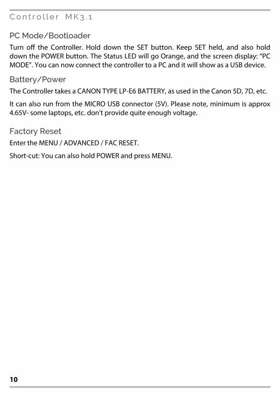
PC Mode/BootloaderTurn o= the Controller. Hold down the SET button. Keep SET held, and also hold
down the POWER button. The Status LED will go Orange, and the screen display: “PC
MODE”. You can now connect the controller to a PC and it will show as a USB device.
Battery/PowerThe Controller takes a CANON TYPE LP-E6 BATTERY, as used in the Canon 5D, 7D, etc.
It can also run from the MICRO USB connector (5V). Please note, minimum is approx
4.65V- some laptops, etc. don't provide quite enough voltage.
Factory ResetEnter the MENU / ADVANCED / FAC RESET.
Short-cut: You can also hold POWER and press MENU.
10
Controller MK3.1
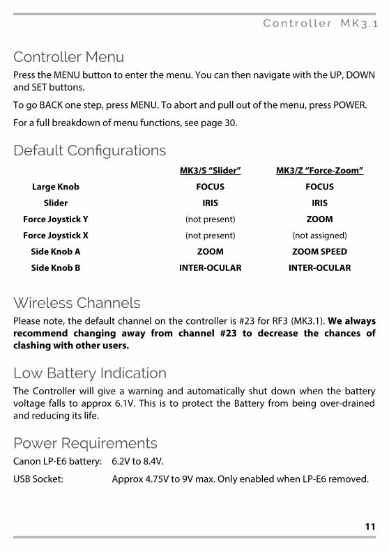
Controller Menu Press the MENU button to enter the menu. You can then navigate with the UP, DOWN
and SET buttons.
To go BACK one step, press MENU. To abort and pull out of the menu, press POWER.
For a full breakdown of menu functions, see page 30.
Default Con>gurationsMK3/S “Slider” MK3/Z “Force-Zoom”
Large Knob O FOCUS FOCUS
Slider O IRIS IRIS
Force Joystick Y O (not present) ZOOM
Force Joystick X O (not present) (not assigned)
Side Knob A O ZOOM ZOOM SPEED
Side Knob B O INTER-OCULAR INTER-OCULAR
Wireless ChannelsPlease note, the default channel on the controller is #23 for RF3 (MK3.1).We alwaysrecommend changing away from channel #23 to decrease the chances ofclashing with other users.
Low Battery IndicationThe Controller will give a warning and automatically shut down when the battery
voltage falls to approx 6.1V. This is to protect the Battery from being over-drained
and reducing its life.
Power RequirementsCanon LP-E6 battery: 6.2V to 8.4V.
USB Socket: Approx 4.75V to 9V max. Only enabled when LP-E6 removed.
11

Receiver MK3.1
6Receiver MK3.1The MK3.1 Receiver is a unique, ultra-compact design, featuring an integral antenna.
Supported Motors3x RTMotion Motors are supported.
The Receiver does not natively support motors from other manufacturers.
Camera SupportAttach the corresponding cable between the CAM port and your camera. There are
cables available for all major cameras (EPIC, ARRI, etc.). You must also select your
camera-type from the Controller Menu, see page 29.
12
Receiver MK3.1
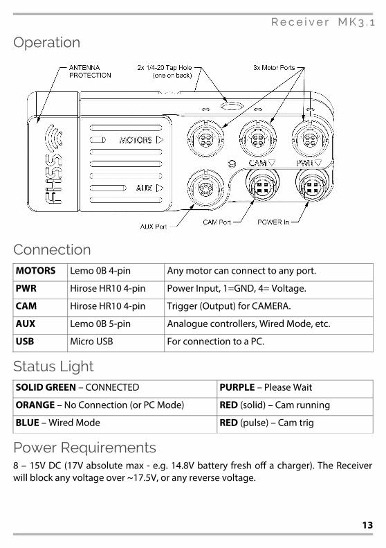
Operation
ConnectionMOTORS Lemo 0B 4-pin Any motor can connect to any port.
PWR Hirose HR10 4-pin Power Input, 1=GND, 4= Voltage.
CAM Hirose HR10 4-pin Trigger (Output) for CAMERA.
AUX Lemo 0B 5-pin Analogue controllers, Wired Mode, etc.
USB Micro USB For connection to a PC.
Status LightSOLID GREEN – CONNECTED PURPLE – Please Wait
ORANGE – No Connection (or PC Mode) RED (solid) – Cam running
BLUE – Wired Mode RED (pulse) – Cam trig
Power Requirements8 – 15V DC (17V absolute max - e.g. 14.8V battery fresh o= a charger). The Receiver
will block any voltage over ~17.5V, or any reverse voltage.
13
Receiver MK3.1
AUX Port The AUX port is a multi-use port, supporting the use of Analogue controllers
(Knob/pot, Rocker, Force Joystick), Wired-Mode operation (connect the Controller to
the Receiver directly, to bypass the wireless), as well as TTL-level serial
communication.
Available Modes of Operation The following functions are supported by the AUX port.The AUX port must be
con⌧gured in the appropriate mode (see page30) – it does NOT automatically detect
which of the following modes you wish to enable.
Slave Controllers (aka, Analogue Controllers)Slave controllers (thumbwheel, rocker, etc.) directly connect to the AUX port, and can
be con⌧gured to control any available axis (Focus, Iris, etc.). Run/Stop triggering is
also supported, provided that you have an appropriate cable connected to your
camera from a CAM port.
Wired Mode (bypass Wireless)Devices which have a 5-pin WIRED MODE socket (such as a Controller MK3.1) can
connect to the AUX port via a suitable wired-mode cable. The Status LED on both
devices will go BLUE to indicate that a connection has been made, and that Wireless
transmission is disabled.
Setting the AUX PORT's ModeThe AUX port must be in the correct mode. The setting is remembered after power-
cycling.
To con⌧gure the AUX PORT, use the CONTROLLER. Enter the MENU, then select AUX.
14
LATITUDE Devices
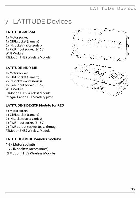
7LATITUDE DevicesLATITUDE-MDR-M
1x Motor socket
1x CTRL socket (camera)
2x IN sockets (accessories)
1x PWR input socket (8-15V)
WIFI Module
RTMotion FHSS Wireless Module
LATITUDE-MDR-MB
1x Motor socket
1x CTRL socket (camera)
2x IN sockets (accessories)
1x PWR input socket (8-15V)
WIFI Module
RTMotion FHSS Wireless Module
Integral Canon LP-E6 battery plate
LATITUDE-SIDEKICK Module for RED
3x Motor socket
1x CTRL socket (camera)
2x IN sockets (accessories)
1x PWR input socket (8-15V)
2x PWR output sockets (pass-through)
RTMotion FHSS Wireless Module
LATITUDE-OMOD (various models)
1-3x Motor socket(s)
1-2x IN sockets (accessories)
RTMotion FHSS Wireless Module
15
LATITUDE Devices
FunctionalityLatitude MDRs are con⌧gured via the CONTROLLER, once a wireless connection is
established.
Camera SocketConnect the appropriate cable between the LATITUDE's CTRL socket and the camera.
Select MENU / Camera / <camera type> to enable run-stop.
IN-1 SocketSupports a SLAVE CONTROLLER, a SMART CONTROLLER and ⌧rmware updating (via
cable RTM-8551). Con⌧gure function via CONTROLLER MENU / AUX.
By default, the Slave Controller button (when attached to IN-1) does the following;
[Button Press] => Camera Run/Stop.
[Hold Button, 3 seconds] => Limit rotation range. Release button to apply.
[Hold Button, 6 seconds] => Clear rotation range limit.
IN-2 SocketSupports a SLAVE CONTROLLER. Con⌧gure function via CONTROLLER MENU / AUX.
By default, the Slave Controller button (when attached to IN-1) does the following;
[Button Press] => Recalibrate Lens.
[Hold Button, 3 seconds] => Limit rotation range. Release button to apply.
[Hold Button, 6 seconds] => Clear rotation range limit.
PWR SocketPower in, recommended supply is a 14.8V battery. Absolute max 17V.
MOTOR SocketSupports 1x RTMotion Motor, or 2x via a Y splitter cable.
16

LATITUDE Devices
CTRL SocketContains sophisticated circuitry to support a wide range of cameras, from RED CTRL
(serial), ARRI (gnd-gnd low pulse), RED EPIC (3v3), Sony, Canon and Blackmagic
(LANC).
For full control of RED cameras, you must use a CTRL-CTRL cable. For run/stop
triggering of other cameras, use an appropriate cable for the camera type.
Note: You must con:gure LATITUDE for camera-type in... CONTROLLER MENU / Camera.
Standalone LATITUDE-MDR operating modesStandalone Latitude variants (i.e. not the Sidekick or OMOD integrated versions) have
the ability to switch into multiple operating modes:-
Standard Mode (Receiver/MDR) – GREEN LIGHT
This is the normal operating mode. The LATITUDE box will accept thumbwheel
and/or Controller (wireless) signals, and forward the commands to the Motor(s) and
Camera.
The WiFi Access Point(page19)
is also enabled, adding full WIFI / FoolControl capability
to DSMC and DSMC2 cameras.
Transmitter Mode – PINK LIGHT 1
In Transmitter Mode, the LATITUDE will route the input signals (i.e. plugged into IN-1,
IN-2) over the RF link to the LATITUDE (or Receiver MK3.1) on camera.
This enables many unique con⌧gurations, including using two thumbwheels (plus
LATITUDE) on a Directors' Monitor to control Focus/Iris and run/stop.
Long Range FoolControl 2 – If you connect your iPhone to the WIFI hotspot of aLATITUDE in Transmitter mode, the LATITUDE will re-transmit the FoolControl comms
over the long-range RF link to a LATITUDE on-camera. This massively increases the
usable range of FoolControl, and is particularly suited for Drone work.
Note: initially there will be some tra<c-shaping used to ensure that the FoolControl datadoesn't interfere with the core FIZ transmission. This will be re:ned in due course.
1 Transmitter Mode will be enabled in Firmware Version 1.2
2 Long-Range FoolControl is expected to be included in Firmware Version 1.3
17
LATITUDE Devices
Note: The “Transmitter” LATITUDE must be set to the same RF Channel as theStandard/Receiver LATITUDE. Currently you must do this manually (by connecting theCONTROLLER to each LATITUDE and ensuring they are on the same RF Channel. In a future:rmware update, it will be possible to connect the two LATITUDEs together via a 5-pin lemocable (IN-1 to IN-1) and have them automatically sync.
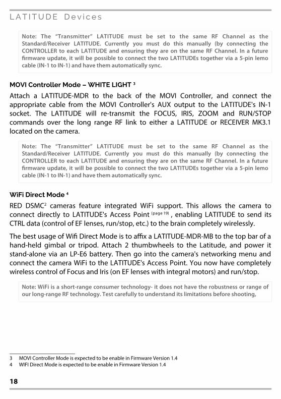
MOVI Controller Mode – WHITE LIGHT 3
Attach a LATITUDE-MDR to the back of the MOVI Controller, and connect the
appropriate cable from the MOVI Controller's AUX output to the LATITUDE's IN-1
socket. The LATITUDE will re-transmit the FOCUS, IRIS, ZOOM and RUN/STOP
commands over the long range RF link to either a LATITUDE or RECEIVER MK3.1
located on the camera.
Note: The “Transmitter” LATITUDE must be set to the same RF Channel as theStandard/Receiver LATITUDE. Currently you must do this manually (by connecting theCONTROLLER to each LATITUDE and ensuring they are on the same RF Channel. In a future:rmware update, it will be possible to connect the two LATITUDEs together via a 5-pin lemocable (IN-1 to IN-1) and have them automatically sync.
WiFi Direct Mode 4
RED DSMC2 cameras feature integrated WiFi support. This allows the camera to
connect directly to LATITUDE's Access Point(page19)
, enabling LATITUDE to send its
CTRL data (control of EF lenses, run/stop, etc.) to the brain completely wirelessly.
The best usage of Wi⌧ Direct Mode is to a;x a LATITUDE-MDR-MB to the top bar of a
hand-held gimbal or tripod. Attach 2 thumbwheels to the Latitude, and power it
stand-alone via an LP-E6 battery. Then go into the camera's networking menu and
connect the camera WiFi to the LATITUDE's Access Point. You now have completely
wireless control of Focus and Iris (on EF lenses with integral motors) and run/stop.
Note: WiFi is a short-range consumer technology- it does not have the robustness or range ofour long-range RF technology. Test carefully to understand its limitations before shooting,
3 MOVI Controller Mode is expected to be enable in Firmware Version 1.4
4 WIFI Direct Mode is expected to be enable in Firmware Version 1.4
18
LATITUDE Devices
Changing LATITUDE operating modeWhile fully powered on, press the LEFT recessed button. With each press, it will cycle
between available operating modes. Please note: additional operating modes will be
added in future, check for an updated Operating Manual.
CTRL Integration for RED DSMC and DSMC2When connected to a RED DSMC or DSMC2 camera via CTRL cable, LATITUDE has
deep integration and control of the camera brain via RED's 3rd party integration
programme.
Initial features include;
– Control of Focus/ Iris via internal motors for EF and Nikon lenses with
integrated motors.
– Mapping Shutter and ISO to Controller input knobs.
Additional capabilities will be added via ⌧rmware updates soon.
WiFi Access PointLATITUDE versions with a WiFi module o=er a Hotspot/ Access Point capability,
enabling full support for the FoolControl app for iOS and Mac.
Default SSID LATITUDE-#### (last 4 digits of the device serial no.)
Default Password latitude (all lower case)
Admin URL http://192.168.0.1 (available once connected)
Admin Username admin
Admin Password PASSWORD
19

MK3.1 Motor
8MK3.1 MotorA powerful and quiet lens motor with smooth performance. The brush-less vector-
drive gives unparalleled smoothness during high-torque/ slow-speed moves.
WarningsThe motor is a powerful device which is capable
of causing injury or damage.
• Never touch the drive gear when the
device is powered on.
• The motor is not to be used on extremely
sti= or damaged lenses.
• The motor requires no user maintenance.
Opening the motor can a=ect its internal
calibration and voids the warranty.
• The motor body is used as a heat-sink for
the brushless windings, therefore it will
get warmer than a brush-type motor.
Attaching to a camera rigA;x the motor to the rods, but don't yet mesh the drive gear to the lens gear. Rotate
the focus ring so that it is not too close to either end stop. Now mesh the gears, and
plug the Digital Motor into the Receiver. The Digital Motor will begin its Auto-
Calibration Routine.
Accuracy & Electronic Backlash CompThe MK3.x motor features a high-precision encoder that will never lose steps. If you
see evidence of backlash a=ecting accuracy, please make sure that your mount, rails
and camera are extremely rigid, as mounting 6ex is the main cause of inaccuracy.
Unique electronic backlash compensation is calibrated at the factory.
20

MK3.1 Motor
Focus/Iris/Zoom AssignmentThe Digital Motor is internally assigned a “Motor Class”, which is saved to non-volatile
memory. The motor will identify itself to the CONTROLLER via its SERIAL NUMBER
(lasered onto the motor back, example: 0500). To change the class of a Digital Motor,
or other performance parameters (performance mode, direction of rotation, etc.)
please refer to the manual for the Controller.
Speci>cationsMax Allowable Torque: 2.2Nm
Standard Gear: 0.8 mod, 50 Teeth
Nominal Current: Approx 0.4-1.1A loaded
Power Requirements: 6.5 - 17V
21

Slave Controller – Thumbwheel
9Slave Controller – Thumbwheel
Features• Strong, lightweight Alu construction.
Knurled thumb/⌧nger wheel.
• Bracket. Sized for common
professional stabiliser gimbals.
• Hard stops.
• Record trigger button.
• Adjustable mounting angle via ARRI-
style rosette.
Usage & Con>guration
Receiver MK3.1
Connect to the AUX socket.
LATITUDE
Connect to the IN-1 or IN-2 socket. Be default, IN-1 is FOCUS and IN-2 is IRIS.
Con5guration
The input must be enabled and con⌧gured correctly. Go to;
CONTROLLER MENU … AUX
Con⌧gure the appropriate input, it should be con⌧gured as type “KNOB”.
22
Smart Knob
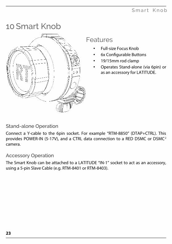
10Smart Knob
Features• Full-size Focus Knob
• 6x Con⌧gurable Buttons
• 19/15mm rod clamp
• Operates Stand-alone (via 6pin) or
as an accessory for LATITUDE.
Stand-alone OperationConnect a Y-cable to the 6pin socket. For example “RTM-8850” (DTAP+CTRL). This
provides POWER-IN (5-17V), and a CTRL data connection to a RED DSMC or DSMC2
camera.
Accessory OperationThe Smart Knob can be attached to a LATITUDE “IN-1” socket to act as an accessory,
using a 5-pin Slave Cable (e.g. RTM-8401 or RTM-8403).
23

Updating Firmwares
11Updating Firmwares
IntroductionUpdating the device ⌧rmware is required take advantage of new features, bug ⌧xes,
and general usability improvements based on feedback.
CautionAlthough the ⌧rmware updating process usually goes smoothly, very occasionally
users may need additional support. For that reasonwe do not recommend
performing an update immediately before a shoot, as it does not leave enough time
for troubleshooting and support. See page 28 for ⌧rmware update troubleshooting.
RequirementsA PC running WinXP or newer, or a Mac running a recent version of OSX.
Note: On Windows, the :rst time you connect your device your operating system may installHID “Human interface device” drivers and require you to restart your computer. This is normal.
Download the Latest FirmwaresVisit: rtmotion.com/knowledge
Download and install the latest version for your platform. The package includes the
Firmware Updater application itself, plus the latest Device Firmwares.
Follow @rtmotion on Twitter to be alerted to new features and important updates.
24
Updating Firmwares
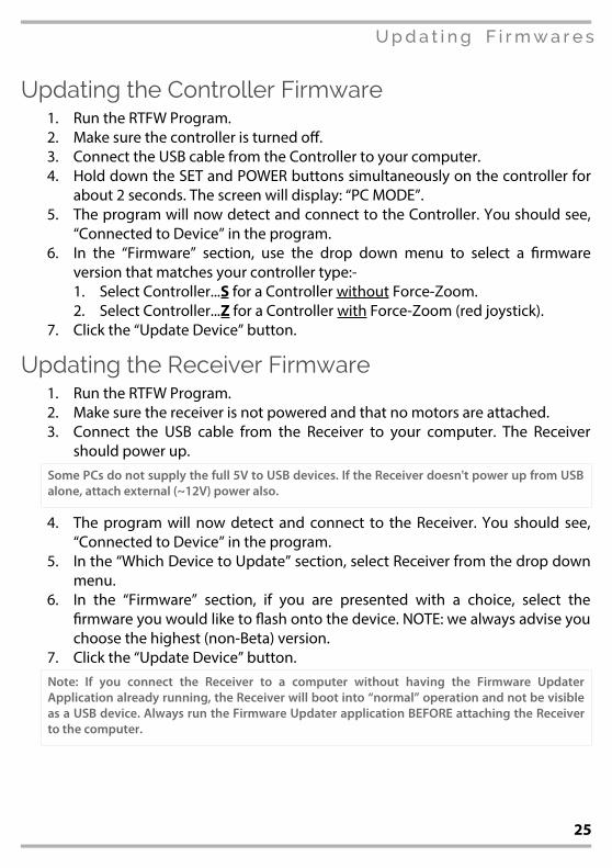
Updating the Controller Firmware1.Run the RTFW Program.
2.Make sure the controller is turned o=.
3.Connect the USB cable from the Controller to your computer.
4.Hold down the SET and POWER buttons simultaneously on the controller for
about 2 seconds. The screen will display: “PC MODE”.
5.The program will now detect and connect to the Controller. You should see,
“Connected to Device” in the program.
6.In the “Firmware” section, use the drop down menu to select a ⌧rmware
version that matches your controller type:-
1.Select Controller...S for a Controller without Force-Zoom.2.Select Controller...Z for a Controller with Force-Zoom (red joystick).
7.Click the “Update Device” button.
Updating the Receiver Firmware1.Run the RTFW Program.
2.Make sure the receiver is not powered and that no motors are attached.
3.Connect the USB cable from the Receiver to your computer. The Receiver
should power up.
Some PCs do not supply the full 5V to USB devices. If the Receiver doesn't power up from USBalone, attach external (~12V) power also.
4.The program will now detect and connect to the Receiver. You should see,
“Connected to Device” in the program.
5.In the “Which Device to Update” section, select Receiver from the drop down
menu.
6.In the “Firmware” section, if you are presented with a choice, select the
⌧rmware you would like to 6ash onto the device. NOTE: we always advise you
choose the highest (non-Beta) version.
7.Click the “Update Device” button.
Note: If you connect the Receiver to a computer without having the Firmware UpdaterApplication already running, the Receiver will boot into “normal” operation and not be visibleas a USB device. Always run the Firmware Updater application BEFORE attaching the Receiverto the computer.
25

Updating Firmwares
Updating a Motor1.Run the RTFW Program.
2.Make sure the Receiver is not powered and that no motors are attached.
3.Connect the USB cable from the Receiver to your computer. The Receiver
should power up.
4.The program will now detect and connect to the Receiver. You should see,
“Connected to Device” in the program.
5.Attach 12-17V power to the Receiver.
6.In the “Which Device to Update” section, select Motor from the drop down
menu.
7.In the “Firmware” section, if you are presented with a choice, select the
⌧rmware you would like to 6ash onto the device. NOTE: we always advise you
choose the highest (non-Beta) version.
8.Click the “Update Device” button.
9.Attach ONE motor to the Receiver. The update process should begin
automatically once the motor is detected.
10.When the motor begins moving, detach it from the Receiver. The process is
complete.
11.If you need to update another motor, go to step 8.
Note: You can only update one motor at a time. Do not attach more than one motor or theupdate will fail.
26

Updating Firmwares
Updating a LATITUDE-MDR or LATITUDE-SIDEKICK1.Run the RTFW Program.
Note: Always run the Firmware Updater application BEFORE attaching the LATITUDE to thecomputer.
2.Make sure the LATITUDE device is not powered and that no motors are
attached.
3.Connect the USB cable from the LATITUDE to your computer. The LATITUDE
should power up.
Some PCs do not supply the full 5V to USB devices. If the LATITUDE doesn't power up from USBalone, attach external (~12V) power also.
4.The program will now detect and connect to the LATITUDE. You should see,
“Connected to Device” in the program.
5.In the “Which Device to Update” section, select LATITUDE from the drop
down menu.
6.In the “Firmware” section, if you are presented with a choice, select the
⌧rmware you would like to 6ash onto the device. NOTE: we always advise you
choose the highest (non-Beta) version.
7.Click the “Update Device” button.
Updating a LATITUDE-OMOD1.Run the RTFW Program.
2.Turn the Camera/OMOD o= completely.
3.Attach the USB=>5pin-Lemo cable (RTM-8551) between the IN-1 socket and
the PC/Mac.
4.Power on the Camera/OMOD.
5.The program will now detect and connect to the LATITUDE. You should see,
“Connected to Device” in the program.
6.In the “Which Device to Update” section, select LATITUDE from the drop
down menu.
7.In the “Firmware” section, if you are presented with a choice, select the
⌧rmware you would like to 6ash onto the device. NOTE: we always advise you
choose the highest (non-Beta) version.
8.Click the “Update Device” button.
27
Updating Firmwares
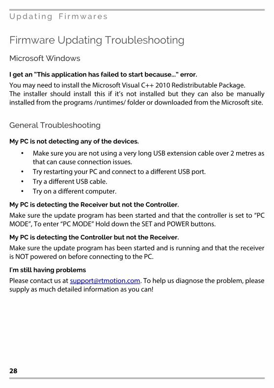
Firmware Updating Troubleshooting
Microsoft Windows
I get an “This application has failed to start because...” error.
You may need to install the Microsoft Visual C++ 2010 Redistributable Package.
The installer should install this if it’s not installed but they can also be manually
installed from the programs /runtimes/ folder or downloaded from the Microsoft site.
General Troubleshooting
My PC is not detecting any of the devices.
• Make sure you are not using a very long USB extension cable over 2 metres as
that can cause connection issues.
• Try restarting your PC and connect to a di=erent USB port.
• Try a di=erent USB cable.
• Try on a di=erent computer.
My PC is detecting the Receiver but not the Controller.
Make sure the update program has been started and that the controller is set to “PC
MODE”, To enter “PC MODE” Hold down the SET and POWER buttons.
My PC is detecting the Controller but not the Receiver.
Make sure the update program has been started and is running and that the receiver
is NOT powered on before connecting to the PC.
I'm still having problems
Please contact us [email protected]. To help us diagnose the problem, please
supply as much detailed information as you can!
28
Menu Tree (via Controller)
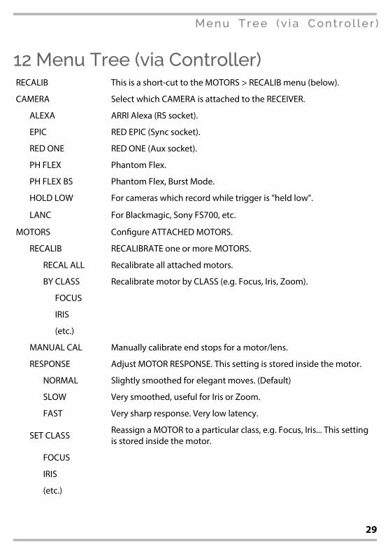
12Menu Tree (via Controller)RECALIB This is a short-cut to the MOTORS > RECALIB menu (below).
CAMERA Select which CAMERA is attached to the RECEIVER.
ALEXA ARRI Alexa (RS socket).
EPIC RED EPIC (Sync socket).
RED ONE RED ONE (Aux socket).
PH FLEX Phantom Flex.
PH FLEX BS Phantom Flex, Burst Mode.
HOLD LOW For cameras which record while trigger is "held low".
LANC For Blackmagic, Sony FS700, etc.
MOTORS Con⌧gure ATTACHED MOTORS.
RECALIB RECALIBRATE one or more MOTORS.
RECAL ALL Recalibrate all attached motors.
BY CLASS Recalibrate motor by CLASS (e.g. Focus, Iris, Zoom).
FOCUS
IRIS
(etc.)
MANUAL CAL Manually calibrate end stops for a motor/lens.
RESPONSE Adjust MOTOR RESPONSE. This setting is stored inside the motor.
NORMAL Slightly smoothed for elegant moves. (Default)
SLOW Very smoothed, useful for Iris or Zoom.
FAST Very sharp response. Very low latency.
SET CLASSReassign a MOTOR to a particular class, e.g. Focus, Iris... This setting
is stored inside the motor.
FOCUS
IRIS
(etc.)
29

Menu Tree (via Controller)
SET SERIALChange the internal serial number of a motor. This setting is stored.
inside the motor.
ACCURACY
Alter motor’s factory calibrated backlash compensation. Attach the
motor to a lens and then run this routine. Adjust the number until
the motor reaches the same point from both directions. This usually
around 10. Please note that your mount should be very rigid.
SCREEN Change OLED settings
HIGH Full brightness for daytime. Status LED also bright.
LOW Low brightness for night/indoor. Status LED dim.
OFF OLED disabled (menu is still active). Status LED dim.
FLIP KNOB Short cut which 6ips (reverses) the MAIN KNOB rotation.
WIRELESS Wireless settings. The RECEIVER (if powered on) will copy.
RANGE Select Controller transmission power.
USA MAX Maximum Range legal in USA.
EU MAX Maximum Range legal in EU and most of the world.
MED Medium Range (best balance of range and battery life).
LOW Required when very close to camera. (Default)
RESET Force the wireless module to reboot. Debug feature, to be removed.
INPUTS Con⌧gure the physical knobs/ slider on the controller.
AXIS Which INPUT (Knob, Slider) should control which AXIS (Focus, Iris) ?
FOCUS O KNB The FOCUS axis is controlled by KNB, i.e. main knob.
IRIS O SLI The IRIS axis is controlled by SLI, i.e. the slider.
etc.
FLIP Flip the direction of INPUTS. i.e. make the lens rotate in REVERSE.
KNOB = Y The main knob is set to FLIP mode (reverse).
SLIDER = N The slider is NOT set to 6ip.
etc.
RECAL KNOBRecon⌧gure the physical stops for the MAIN KNOB. If you are unable
to reach the end of the lens travel, run this function.
AUX Con⌧gure the auxiliary port on the RECEIVER.
30

Menu Tree (via Controller)
MODE What function to assign to the AUX PORT?
OFF Disable the AUX port. Recommended if port not in use.
WIREDCon⌧gure AUX port for WIRED MODE (i.e. wire from Controller ->
Receiver to bypass radio).
KNOB You have a KNOB or THUMBWHEEL attached to the AUX PORT.
ROCKER You have a ROCKER attached to the AUX PORT.
FORCE You have a FORCE SENSOR attached to the AUX PORT.
AXISWhich axis to control with the attached AUX input device? N.B. This
does not apply if you are in WIRED MODE.
FOCUS
IRIS
(etc.)
MODE B As “Mode” above, but for input axis B (for use with splitter).
AXIS B As “Axis” above, but for input axis B (for use with splitter).
BUTTONS
BT 1 Assign a function to the physical UP button.
BT 2 Assign a function to the physical DOWN button.
BT 3 Assign a function to the physical SET button.
BT 4 Assign a function to the physical POWER+UP button combination.
BT 5Assign a function to the physical POWER+DOWN button
combination.
BT 6 Assign a function to the physical POWER+SET button combination.
ADVANCED Advanced functions for debugging and technician use only.
SERIAL Change the Serial # of the handset (not recommended).
FAC RESETTake the CONTROLLER back to factory default settings. This DOES NOT roll back the 'rmware version. It also does not change the settings stored inside the motors (class, response, etc.)
DEBUGGING Raw read-outs to use for diagnosing issues.
RADIO Enable/Disable the radio. (Radio is automatically disabled when wired mode is used).
31

Technical Reference
13Technical Reference
Compatibility Guidance
MotorsAll MK3.x generation motors will work with any MK3.x generation Controller/Receiver
sets.
Controller / Receiver Sets – RF3Controllers and Receivers must be of the same “RF” generation.
• MK3.0 Controller/Receiver sets have RF2 generation wireless modules and
have been obsoleted. Heavily discounted upgrade routes are available.
• MK3.1 Controller/Receiver sets and LATITUDE units have RF3 generation
wireless modules.
MK1 and MK2 generation systems.These systems are now “end-of-life”. We will strive to support them as long as
possible, but we recommend that these systems are upgraded to the present
generation to ensure the best support.
32
Technical Reference
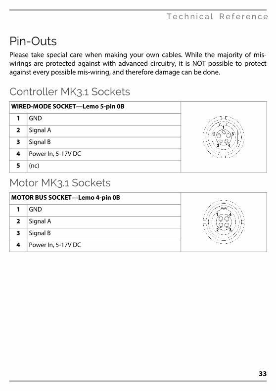
Pin-OutsPlease take special care when making your own cables. While the majority of mis-
wirings are protected against with advanced circuitry, it is NOT possible to protect
against every possible mis-wiring, and therefore damage can be done.
Controller MK3.1 SocketsWIRED-MODE SOCKET–Lemo 5-pin 0B
1 GND
2 Signal A
3 Signal B
4 Power In, 5-17V DC
5 (nc)
Motor MK3.1 SocketsMOTOR BUS SOCKET–Lemo 4-pin 0B
1 GND
2 Signal A
3 Signal B
4 Power In, 5-17V DC
33

Technical Reference
Receiver MK3.1 Sockets3x MOTOR SOCKETS–Lemo 4-pin 0B
1 GND
2 Signal A
3 Signal B
4 Power OUT
POWER SOCKET–Hirose HR10 4-pin
1 GND
2 CAM TRIG (Output) – DO NOT expose to 12V
3 (currently not used) – DO NOT expose to 12V
4 Power IN, 5-17V DC (17.5V absolute max)
CAMERA SOCKET–Hirose HR10 4-pin
1 GND
2 CAM TRIG (Output)
3 (currently not used)
4 (nc)
AUX SOCKET–Lemo 5-pin 0B
1 GND
2 Analogue-in X (/Signal A)
3 Analogue-in Y (/Signal B)
4 3V3 out (0.2A max)
5 /CAM TRIG (Input, momentary GND to trigger)
34

Technical Reference
LATITUDE SocketsPWR-IN Socket – Lemo 2-pin 0B
1 GND
2 Power In, 7-17V DC
MOTOR Socket – Lemo 4-pin 0B
1 GND
2 Signal A
3 Signal B
4 Power In, 5-17V DC
CTRL Socket – Lemo 4-pin 00B
1 GND
2 RS232-TX
3 Camera Trigger (non-DSMC2)
4 RX232-RX
IN-1/IN-2 Sockets – Lemo 5-pin 0B
1 GND
2 A / UART-RX
3 X / UART-TX
4 3V3 Ref
5 GPIO
PWR-OUT Socket – Lemo 2-pin 0B
1 GND
2 Power Out – Pass-through directly from PWR-IN.
35
Technical Reference
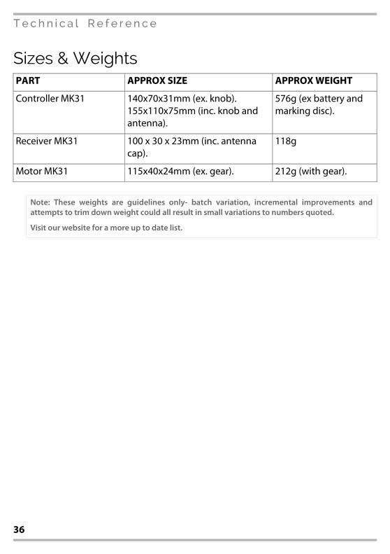
Sizes & WeightsPART APPROX SIZE APPROX WEIGHT
Controller MK31 140x70x31mm (ex. knob).
155x110x75mm (inc. knob and
antenna).
576g (ex battery and
marking disc).
Receiver MK31 100 x 30 x 23mm (inc. antenna
cap).
118g
Motor MK31 115x40x24mm (ex. gear). 212g (with gear).
Note: These weights are guidelines only- batch variation, incremental improvements andattempts to trim down weight could all result in small variations to numbers quoted.
Visit our website for a more up to date list.
36

Quick Troubleshooting
14Quick TroubleshootingFor the latest troubleshooting information, visit our Knowledgebase on your
computer, tablet or phone:-
rtmotion.com/knowledge
Table of Contents14. Quick Troubleshooting...............................................................................................................37
. The Wireless won’t connect .........................................................................................37
. My Motor calibrates but then won’t move..............................................................37
. The Motor rotates in the wrong direction...............................................................37
. The Motor is in a strange mode, it is slow (or jittery fast)...................................38
. The Zoom Motor calibrates but then doesn’t respond.......................................38
. When very close to camera, the wireless cuts out................................................38
The Wireless won’t connect Your Controller/Receiver may not be in the correct channel.
Try from the Controller menu:- MENU / Wireless / Find Receiver.
If that doesn't help- What is the STATUS LED colour? The boot sequence should be:-
• ORANGE (pc mode)
• PURPLE (wireless module setting reset - only happens after a factory reset or
⌧rmware update)
• WHITE (wireless module is initialising)
• YELLOW (booted OK, waiting for wireless pairing)
• GREEN (wireless has paired correctly)
If your device does not boot past WHITE, try power cycling or updating its ⌧rmware.
My Motor calibrates but then won’t movePerhaps the motor is not set to the correct CLASS. Go to MENU... MOTORS... CHANGE
CLASS
The Motor rotates in the wrong directionRotation Flip is set by the CONTROLLER. To 6ip the Focus knob, select MENU / FLIP
37
Quick Troubleshooting
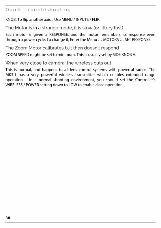
KNOB. To 6ip another axis... Use MENU / INPUTS / FLIP.
The Motor is in a strange mode, it is slow (or jittery fast)Each motor is given a RESPONSE, and the motor remembers its response even
through a power cycle. To change it, Enter the Menu … MOTORS … SET RESPONSE.
The Zoom Motor calibrates but then doesn’t respondZOOM SPEED might be set to minimum. This is usually set by SIDE KNOB A.
When very close to camera, the wireless cuts outThis is normal, and happens to all lens control systems with powerful radios. The
MK3.1 has a very powerful wireless transmitter which enables extended range
operation – in a normal shooting environment, you should set the Controller’s
WIRELESS / POWER setting down to LOW to enable close operation.
38

Usage and Care
15Usage and Care
Usage & EnvironmentEnclosures should not be opened, doing so can cause damage, and voids the
warranty. The MK3.1 system is not water proof- do not expose the system to any type
of water, or condensation-prone situations.
Accidental DamageThe MK3.1 is a complex electro-mechanical system and should be treated with the
care you would a camera or lens. Accidental damage is not covered by warranty.
16Warranty and Servicing
12/24 Month WARRANTYRT Motion Systems products are guaranteed for a period of 12 months with e=ect
from the date of delivery (or date-of-purchase, if purchased from a 3rd party) and
applies to defects arising from defective materials and or faulty workmanship that
become evident during the guarantee period only and does not include consumable
items.This guarantee is extended to 24 months if purchased direct from the
manufacturer, or registered with the manufacturer within 3 months of purchase from
a 3rd party. When purchased from a Reseller, the customer's contract and Warranty is
wholly with the reseller.The manufacturer will repair or replace the product at their
discretion subject to the following. That the product has been used in accordance
with the guidelines as detailed in the product manual and that it has not been
subjected to misuse, abuse or used for a purpose for which it was not intended. That
is has not been tampered with or has been serviced by unauthorised persons. It shall
be the customer's responsibility to return the product at their cost ensuring that the
product is adequately packed to prevent transit damage. If the product was
purchased from a 3rd party such as a distributor, you must ⌧rst contact the reseller for
return/repair instructions. The manufacturer shall not be liable for any consequential
loss or damage arising from faults that occur either within, or outwith the guarantee
period. This guarantee is in addition to and does not a=ect any rights which the
consumer may have by virtue of UK or EU law.
39

Info & Troubleshooting
From a computer, phone or tablet:
rtmotion.com/knowledge
RTMotion9 Lansdown, Stroud, Glos, GL5 1BB, UK
(By appointment only)
Tel: +44 2030 210 803
Email: [email protected]
Note: Do not return any goods without contacting us for Return Instructions.