RTI Light Probe
32
RTI article number: 9630507-00 RTI Light Probe RTI Light Probe User’s Manual – English – Version 2019.12B For Measurements Of: Luminance Illuminance (cd/m²) (lux)
Transcript of RTI Light Probe

RTI article number: 9630507-00
RTI Light Probe
RTI Light Probe User’s Manual – English – Version 2019.12B
For Measurements Of:
Luminance Illuminance (cd/m²) (lux)


NOTICE
RTI Light Probe Manual 2019.12B I-1
NOTICE RTI Group AB reserves all rights to make changes in the detector and the information in this document without notice. RTI Group AB assumes no responsibility for any errors or consequential damages that may result from the use or misinterpretation of any information contained in this document.
Copyright © 1999-2019 by RTI Group AB. All rights reserved. Contents of this document may not be reproduced in any form without permission from RTI. RTI Group AB Phone: Int +46 31 746 36 00 Flöjelbergsgatan 8 C SE-431 37 MÖLNDAL E-mail: info@ rtigroup.com Sweden Web: www.rtigroup.com

PREFACE
I-2 2019.12B RTI Light Probe Manual
PREFACE Chapter 1 Gives an introduction to the RTI Light Probe. Chapter 2 Shortly describes the theory of light. Chapter 3 Explains the different parts of the detector system. Chapter 4 Explains how you measure luminance. Chapter 5 Explains how you measure illuminance. Chapter 6 Discussion of cleaning the optic parts. Chapter 7 Specifications Chapter 8 References Index Contains an index register for this manual. It is advisable to read the manual at least once to gain familiarity with the terms used and the capabilities of the RTI Light Probe.
Note! The RTI Light Probe is intended for service and quality control of light sources. It is not intended for use during or together with diagnostic examinations of patients.

Table of Contents
RTI Light Probe Manual 2019.12B 1
Table of Contents
1. INTRODUCTION .......................................................................... 3
2. BASIC LIGHT KNOWLEDGE ...................................................... 4
2.1 What Do We Mean by Light.................................................................. 4
2.2 CIE ......................................................................................................... 4
2.3 The Basic Quantities and Units of Light ............................................. 5 2.3.1 Luminous Flux (lumen, lm) ............................................................. 6 2.3.2 Luminous Intensity (candela, cd) ................................................... 7 2.3.3 Illuminance (lux, lx) ........................................................................ 8 2.3.4 Luminance (cd/m²) ......................................................................... 9
2.4 How Do You Measure Light Compared to Dose Rate ...................... 10
3. THE LIGHT DETECTOR AND ADAPTERS ............................... 12
3.1 RTI Light Probe ................................................................................... 12
3.2 Monitor Adapter .................................................................................. 12
3.3 Lux Adapter......................................................................................... 13
3.4 The Calibration Factor ....................................................................... 15
4. MEASUREMENT OF LUMINANCE (CD/M²) .............................. 16
4.1 Preparing the Detector for Monitor Measurements ......................... 16
4.2 Reset .................................................................................................... 16
4.3 Measurements on Monitors and Film Viewing Boxes ..................... 18
4.4 SMPTE Test Pattern ........................................................................... 18
4.5 Quality Control of a Complete Image Intensifier System ................ 20
4.6 Ambient Light and Other Sources of Error ...................................... 20
5. MEASUREMENT OF ILLUMINANCE (LX) ................................ 22
5.1 Preparing the Detector for Ambient Light (Lux) Measurements .... 22
5.2 Reset .................................................................................................... 22
6. CLEANING PROCEDURES ...................................................... 24
6.1 Cleanliness Observations .................................................................. 24
6.2 Following the Calibration Plan .......................................................... 24
6.3 Cleaning the RTI Light Probe ............................................................ 24 6.3.1 Light Detector ............................................................................... 25 6.3.2 Monitor Adapter ........................................................................... 25

Table of Contents
2 2019.12B RTI Light Probe Manual
6.3.3 Lux Adapter ................................................................................. 25
7. SPECIFICATIONS ..................................................................... 26
8. REFERENCES .......................................................................... 27
9. INDEX ........................................................................................ 28

Chapter 1 Introduction
RTI Light Probe Manual 2019.12B 3
1. INTRODUCTION
The L100 detector was an older light detector for PMX-III, Solidose 300/400, and Barracuda, from RTI Electronics AB. The Piranha Light Probe and now RTI Light Probe (RTI-LP) is based on the L100 but with a newer connector for use with newer multimeters, like Piranha and Cobia. The light detector is intended to be used with different adapters to measure the quantities luminance and illuminance. There is also an adapter for visual definition measurements of the collimator light field of an X-ray unit. The most common applications for the light detector are luminance measurements on monitors and film viewing boxes, and illuminance measurements of ambient light in a room or in front of a monitor. This manual will try to give examples of practical measuring methods and explain the theory behind the units and quantities of light. It is not necessary to completely understand the theory part but it will help you perform more accurate measurements. For those who want to get started right away please read the chapters 4. Measurement of Luminance (cd/m²) and 5. Measurement of Illuminance (lx). It is however recommended that you read the entire manual at least once.

Basic Light Knowledge Chapter 2
4 2019.12B RTI Light Probe Manual
2. BASIC LIGHT KNOWLEDGE
2.1 What Do We Mean by Light We are constantly surrounded by electromagnetic radiation with various wavelengths. This electromagnetic radiation is produced by different sources like e.g. radio transmitters, radar stations, the sun and so on. By light we simply mean that part of this electromagnetic radiation that the human eye can detect, i.e. wavelengths from approximately 380 nm to 760 nm.
2.2 CIE The first to more scientifically examine what wavelengths the human eye can apprehend and the first to define the response of the human eye were the Commission Internationale de l’Eclairage, CIE, in 1924. They discovered that people apprehend the colour green as “stronger” than the colours violet and red. This investigation led to the definition of the CIE photopic response curve where the coefficient Vλ defines the relative “strength” between different wavelengths, as the human eye apprehend it. This curve is shown in figure 1 below.

Chapter 2 Basic Light Knowledge
RTI Light Probe Manual 2019.12B 5
CIE Photopic Response Curve
0,00,10,20,30,40,50,60,70,80,91,0
380 415 450 485 520 555 590 625 660 695 730 765Wavelength (nm)
V-la
mbd
a
Figure 1 The curve illustrates how the human eye apprehend different wavelengths (colours) normalised to 555 nm (the colour green).
In addition to the photopic response curve, which refer to the eye’s daytime adapted state, there also exists a scotopic response curve. This curve refers to how the eye apprehends different colours when it is dark-adapted. The major difference compared to the photopic response is that the eye’s sensitivity is transferred to shorter wavelengths, with peak sensitivity around 510 nm. There is also a notable decrease in sensitivity for the longer wavelengths, i.e. for the colours red, orange, and yellow.
2.3 The Basic Quantities and Units of Light Since light is electromagnetic radiation, although in a certain wavelength range, one would think that it would not be necessary to define certain quantities and units for it. Why not simply use the quantity power and the unit Watt? Well, the fact that light has got a specific wavelength range and the fact that we often use light sources that radiates in a certain direction, are reasons enough for special light quantities and units.

Basic Light Knowledge Chapter 2
6 2019.12B RTI Light Probe Manual
The list of quantities and units below is not to be considered as a complete guide over all possible light quantities and units. There are still many quantities to define and units to derive, not to mention all the non-metric units. The list will however try to explain the basic ones.
2.3.1 Luminous Flux (lumen, lm) Just like a radio antenna can radiate a certain amount of electro-magnetic power a light source can radiate a certain amount of light. But what is a certain amount of light? Think of a light source as an object that radiates photons (this is in fact exactly what it is). Each photon has a certain amount of energy. By, so to speak, counting how many photons that radiates in all direction from the light source per second, we have a measure of the light source’s optical power. The quantity is called luminous flux and the unit is called lumen, abbreviated lm. The relation between lumen and watt is defined by equation 1 below.
1 W = 683 lm at 555 nm (Equation 1) The relation at other wavelengths can be calculated by use of the Vλ-function from the CIE photopic response curve. With the Vλ-function we can se that luminous flux simply is not defined outside the visible spectra. Using the Vλ function and the relation in formula 1 above we can tabulate the conversion factors for different wavelengths as shown in table 1 below.

Chapter 2 Basic Light Knowledge
RTI Light Probe Manual 2019.12B 7
Table 1 Conversion of radiant flux (W) to luminous flux.
wavelength (nm)
radiant flux (W)
luminous flux (lm)
400 450 500 550 555 600 650 700 750
1 1 1 1 1 1 1 1 1
0,3 26
220 679 683 430 73 2,8 0,8
To fully measure the luminous flux from a light source you will need an integrating sphere that collects all light emitted from the source. Note that luminous flux is a property of a specific light source and that it does not matter at what distance you measure or in what direction you look at the source, since you have to collect all emitted light from the specific source.
2.3.2 Luminous Intensity (candela, cd) In most case we are not so interested in a light source’s luminous flux, since that quantity describes how much light that is being radiated in all directions. Often we are more interested in how much light a particular light source radiates in a certain direction, measured at a certain distance. For this purpose, the quantity luminous intensity was defined. The corresponding unit is called candela, abbreviated cd. What we mean with luminous intensity is simply luminous flux per solid angle. By this we can se that the unit candela is the same as lm / sr, where sr is an abbreviation for steradian, the unit for a solid angle. The quantity solid angle and the unit steradian may need further explanation. Imagine a sphere with radius 1 m. Then imagine a cone with its vertex in the centre of that sphere. This cone will occupy a solid angle of 1 sr if it cuts of an area of 1 m² of the surface of the

Basic Light Knowledge Chapter 2
8 2019.12B RTI Light Probe Manual
sphere. By this we can see that the whole hemisphere occupies 4×π (= 12,57) steradians.
By the definition of luminous intensity it is clear that this is a quantity for a specific (point) source, measured at a certain angle, at a certain distance. The latter is due to the inverse square law. The inverse square law states that the intensity per unit area, that a point source radiates, varies in inverse proportion to the square of the distance to the source. Figure 2 tries to explain this. Imagine that a certain amount of photons passes through an area of 1 m², at 3 m distance from the source. When these photons have travelled an additional 3 m they will pass through an area of 4 m². This is due to the laws of geometry.
6 m
1 m
1 m
3 m
2 m
2 m
Figure 2 Illustration of the inverse square law.
This means that a detector (e.g. a human eye) that doubles its distance from a point source will occupy only one quarter of the previous solid angle. Hence the luminous intensity will decrease by a factor of four.
2.3.3 Illuminance (lux, lx) Illuminance is a quantity that describes how much light that falls onto a certain area. The unit for illuminance is called lux, abbreviated lx. In a popular way one could say that measuring illuminance is the same as counting how many photons per second that hit a certain area,

Chapter 2 Basic Light Knowledge
RTI Light Probe Manual 2019.12B 9
e.g. a desk. The official definition of illuminance is luminous flux per unit area. By this we can se that the unit lux is the same as lm / m². Measuring illuminance is useful when we want to know if e.g. our desk is sufficiently lit. In that situation we probably do not care about the number of light sources or at what distances they are positioned. All we care about is how well all the present light sources manage to light up a spot on the desk. There is although nothing that prevents us from examine the contribution from a particular source. If we do so we will notice that the inverse square law is applicable. If we double the distance to the source, the illuminance value will decrease by a factor of four. Illuminance can be measured with the light detector by use of the lux adapter.
2.3.4 Luminance (cd/m²) Luminous intensity is a quantity suitable for a point light source. But what if we want to have a quantity suitable for a relatively flat and uniform light source, like a flat panel monitor, CRT or a film viewing box? The quantity we are looking for is called luminance and it is measured in candela per square meter, abbreviated cd/m². This unit is sometimes also called nit (nt). As the unit implies the official definition is luminous intensity per unit area. The source in this case must not be active like a CRT or a film viewing box. For instance, a wall that reflects light can be considered to be a flat, uniform light source. The important thing is that the source is uniform. This is because of the fact that when you measure luminance you measure at a sample of the surface. This sample must then of course be representative for the whole surface, hence the necessity of uniformity. Otherwise you will have to scan the whole surface and calculate the mean value of your measurements. Since the detector must measure at sample of the surface it is important that it has got a limited field of view. It is also important

Basic Light Knowledge Chapter 2
10 2019.12B RTI Light Probe Manual
that the measuring area is well defined. Some luminance detectors have got optics that allows the user to look at the area that the detector is currently measuring on. A notable thing with a luminance detector is that the measured value is independent of the distance to the surface. Although the inverse square law states that the intensity decreases as the square of the distance, the area seen by the detector increases with the same factor. Thus leaving the same amount of photons to be measured by the detector. The human eye can be thought of as a detector quite similar to a luminance meter. The difference is that the eye perceives brightness and does not measure luminance. Brightness is a subjective attribute of light that humans try to quantify as e.g. dim or bright.
Luminance can be measured with the light detector by use of the monitor adapter. The monitor adapter is however intended to be used by pressing it onto the surface to be measured, not to measure at a distance.
2.4 How Do You Measure Light Compared to Dose Rate
In principle a dose detector and a light detector from RTI Electronics AB work in the same way. Electromagnetic radiation (X-ray and light respectively) is converted to an electric current via a solid state detector and measured by an electrometer. The difference is obviously that the silicon chip in the dose detector must be held in complete darkness while the silicon chip in the light detector must be allowed to be irradiated by light. The latter is however not enough. No matter what light quantity you want to measure, the light detector must have the same spectral response as the human eye. A solid state detector is by nature more sensitive to longer wavelengths than the eye. To compensate for this a glass filter is placed in front of the silicon chip. This filter is called a CIE filter and attenuates the non-wanted wavelengths. Since a light detector should have its largest sensitivity for the green colour the CIE filter usually looks green to a human eye. The CIE filter that RTI Electronics AB use is specially
Chapter 2 Basic Light Knowledge
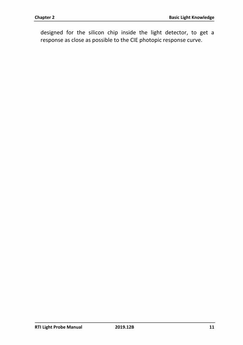
RTI Light Probe Manual 2019.12B 11
designed for the silicon chip inside the light detector, to get a response as close as possible to the CIE photopic response curve.
The Light Detector and Adapters Chapter 3
12 2019.12B RTI Light Probe Manual
3. THE LIGHT DETECTOR AND ADAPTERS
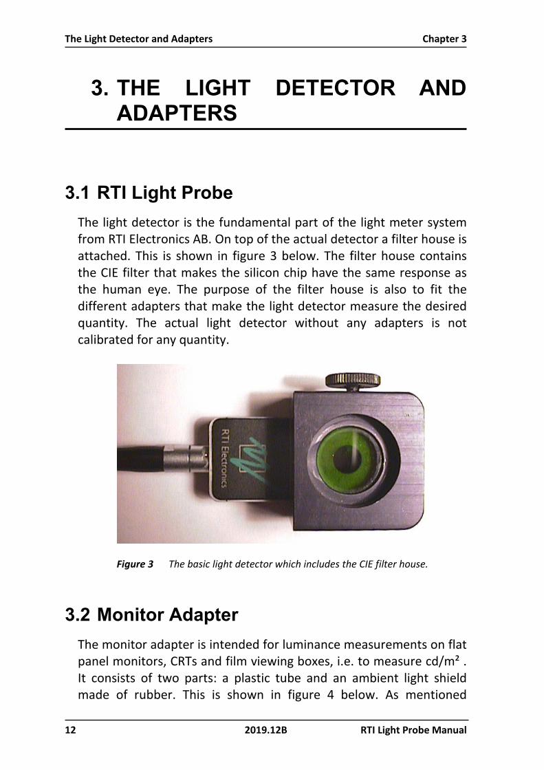
3.1 RTI Light Probe The light detector is the fundamental part of the light meter system from RTI Electronics AB. On top of the actual detector a filter house is attached. This is shown in figure 3 below. The filter house contains the CIE filter that makes the silicon chip have the same response as the human eye. The purpose of the filter house is also to fit the different adapters that make the light detector measure the desired quantity. The actual light detector without any adapters is not calibrated for any quantity.
Figure 3 The basic light detector which includes the CIE filter house.
3.2 Monitor Adapter The monitor adapter is intended for luminance measurements on flat panel monitors, CRTs and film viewing boxes, i.e. to measure cd/m² . It consists of two parts: a plastic tube and an ambient light shield made of rubber. This is shown in figure 4 below. As mentioned

Chapter 3 The Light Detector and Adapters
RTI Light Probe Manual 2019.12B 13
previous a luminance meter must have a limited field of view. In the case of the luminance adapter this is accomplished by pressing the tube against the surface to be measured. The purpose of the ambient light shield is to prevent non-wanted light to interfere with the measurements. This could otherwise be a problem when measuring on not so bright sources like e.g. a CRT. Without the ambient light shield non-wanted light, e.g. from the room, would be reflected via the glass surface of the CRT and would be added to the measured light. A smaller shield is also included to make the easier to position the monitor when the ambient light level is not a major error source. This is also a part of the reason why RTI Electronics AB has chosen not to design a traditional luminance meter, with optics that let you measure at a distance. Such a measurement would obviously be a measurement of not only the source itself but also of the ambient light reflected by e.g. the glass surface of the CRT. The monitor adapter is referenced to as RTI-LP-M.
Figure 4 The monitor adapter with light shutter and ambient light shield.
3.3 Lux Adapter To measure illuminance the detector must be able to collect light from every direction in a half sphere. The contribution from an incidence light beam must follow the cosine function. This is quite natural if we consider how we apprehend the surface of a spot on e.g. a desk. Seen from above at an incidence angle of 0° the projected area of the spot is the same as the real one. When we

The Light Detector and Adapters Chapter 3
14 2019.12B RTI Light Probe Manual
increase the angle of incidence to 60° the projected area decreases by a factor of 0,5, just like cosine 60° equals 0,5. When we have increased the angle of incidence to 90° we of course cannot see the spot, just as cosine 90° equals 0. In theory this sounds easy but in practice there are a few things to consider when designing a lux detector. • First: The surface of the silicon chip will always be shiny. This
means that light that hits the detector from a very large angle of incidence will be reflected by the surface of the silicon chip, thus neglecting the cosine function.
• Second: The actual silicon chip can in most cases not be placed at the surface of the detector. An example of this is the light detector with its CIE filter.
The solution to these problems is the lux adapter, see figure 5. The white plastic inside the aluminium is called a cosine diffuser. The surface of the cosine diffuser is, as the name implies, diffuse. Thus preventing light with a large angle of incidence from being reflected by the surface. The cosine diffuser also leads the light down to the silicon chip, more or less in the same way as an optical fibre can lead light. The lux adapter is referenced to as RTI-LP-L.
Figure 5 The lux adapter with its cosine diffuser. The right picture shows the complete lux adapter set.

Chapter 3 The Light Detector and Adapters
RTI Light Probe Manual 2019.12B 15
3.4 The Calibration Factor Each combination of an adapter and the light detector will get a certain calibration factor at the time of calibration. This calibration factor states the relationship between the quantity that the detector is measuring and the current it produces. To keep track of which calibration factor to use with a certain combination of a light detector and an adapter, the calibration factor is stored inside the RTI light detector connector. Once the calibration factor is known it is stored in the RTI light detector connector. The calibration factor is then read by the instrument when it is connected to the detector.

Measurement of Luminance (cd/m²) Chapter 4
16 2019.12B RTI Light Probe Manual
4. MEASUREMENT OF LUMINANCE (CD/M²)
4.1 Preparing the Detector for Monitor Measurements
Follow these steps to prepare a measurement.
1. If it is not already done, attach the monitor adapter tube to the detector housing. It is important that the monitor adapter is pressed all way down in the detector housing when the screw fixate the tube.
2. Connect the light detector to the EXT input on the Piranha or
Cobia. 3. If not already on, now power on the meter.
4.2 Reset When you are using the Piranha you have to perform a reset before you can start to measure. It is VERY IMPORTANT that no light reaches the detector during the reset procedure. With the monitor

Chapter 4 Measurement of Luminance (cd/m²)
RTI Light Probe Manual 2019.12B 17
adapter with light shutter this is an easy task since the monitor adapter signal is zero until the shutter knob is pressed down. For the Cobia the reset is done automatically. Now you can move the light detector to the measuring point and open the shutter by pressing the knob to stop, hold to collect a light value. After you have released the knob, the meter shows the value in its display until next measurement.

Measurement of Luminance (cd/m²) Chapter 4
18 2019.12B RTI Light Probe Manual
4.3 Measurements on Monitors and Film Viewing Boxes
Attach the ambient light shield to the monitor adapter. You can select between a small and big shield. Place the light detector on the monitor, CRT, or the film viewing box. Make sure the ambient light shield is held flat on to the surface to prevent ambient light from reaching the detector. Press and hold the shutter knob. Read the value on the display of the instrument. Two sample measurements are shown in figure 6 below. If you want to measure on a more precise point of the monitor you should first place the light shield (without the light detector) on the screen by aiming through the centre hole. By holding the light shield with one hand you can attach the light detector with the other hand.
Figure 6 Checking the luminance of a monitor, in this case different grey-level areas. To the right a luminance check of a viewing box is shown.
4.4 SMPTE Test Pattern A common test pattern used when testing CRT is the test pattern specified by the Society of Motion Picture and Television Engineers, SMPTE. This test pattern has, among other features, 11 different

Chapter 4 Measurement of Luminance (cd/m²)
RTI Light Probe Manual 2019.12B 19
areas of grey-scale intensity, ranging from 0 % to 100 %. This test pattern is shown in figure 7.
Figure 7 A SMPTE test pattern with different grey areas and black/white resolution patterns. [Ref. 4]
When measuring on these different grey-scale areas you should have in mind that the luminance of an area NOT is proportional to its grey-scale value. Instead the luminance (L) is related to the grey-scale level (G) by:
L ∝ Gγ (Equation 2) Equation 2 is equivalent to:
log(L) = γ log(G) + C (Equation 3)
In equation 3, C is a constant and γ is the gamma value of the monitor that characterises the relationship between luminance and grey-scale value.
Measurement of Luminance (cd/m²) Chapter 4
20 2019.12B RTI Light Probe Manual
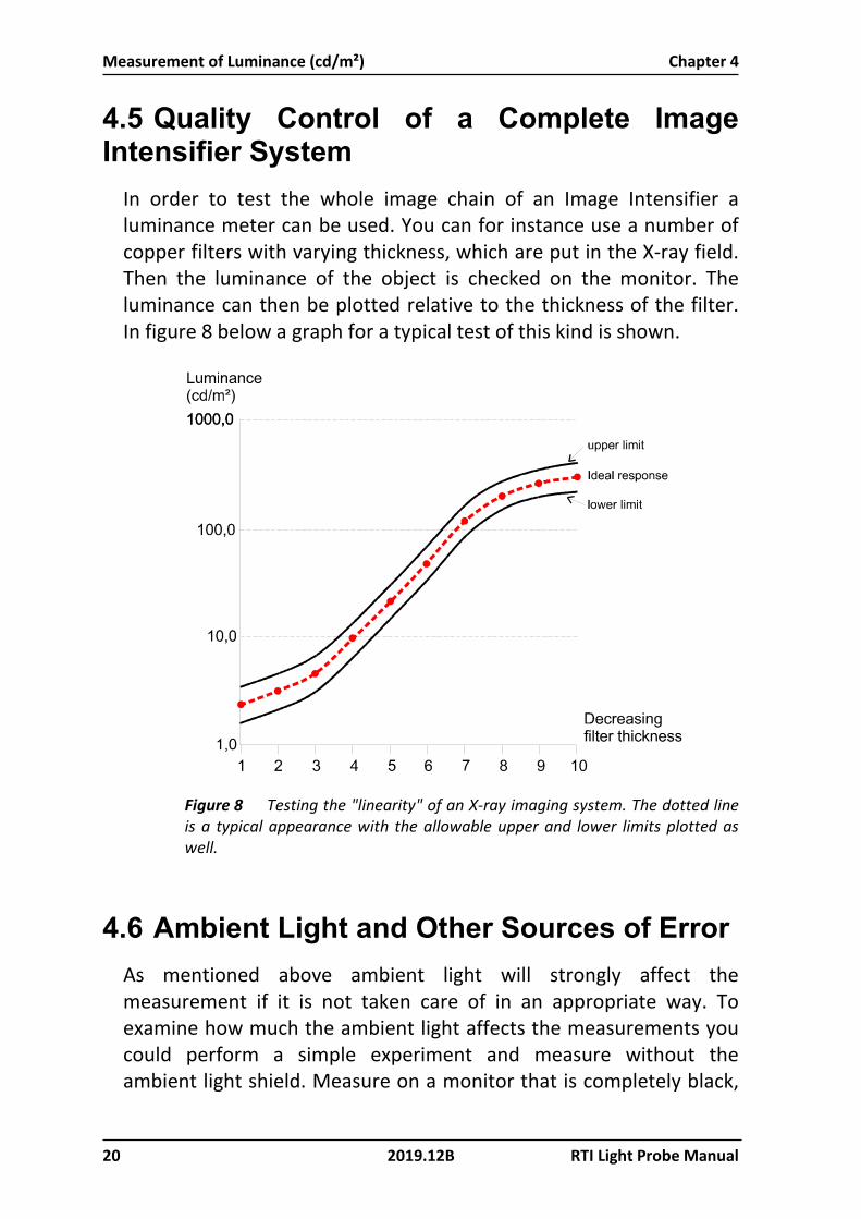
4.5 Quality Control of a Complete Image Intensifier System
In order to test the whole image chain of an Image Intensifier a luminance meter can be used. You can for instance use a number of copper filters with varying thickness, which are put in the X-ray field. Then the luminance of the object is checked on the monitor. The luminance can then be plotted relative to the thickness of the filter. In figure 8 below a graph for a typical test of this kind is shown.
Figure 8 Testing the "linearity" of an X-ray imaging system. The dotted line is a typical appearance with the allowable upper and lower limits plotted as well.
4.6 Ambient Light and Other Sources of Error As mentioned above ambient light will strongly affect the measurement if it is not taken care of in an appropriate way. To examine how much the ambient light affects the measurements you could perform a simple experiment and measure without the ambient light shield. Measure on a monitor that is completely black,

Chapter 4 Measurement of Luminance (cd/m²)
RTI Light Probe Manual 2019.12B 21
i.e. not powered on, and compare the result with measurements performed with the ambient light shield attached. Also measure with and without reduced room illumination. You will notice that the values achieved without the ambient light shield and with normal room illumination differ considerably from the ideal value. Imagine the percentage error you would achieve if you were to measure in this way on the 10 % grey-scale area! Other sources of error are fingerprints and dust on a CRT. Investigations have shown that these smudges can decrease the luminance by as much as 10 % [Ref. 2]. If a CRT is not sufficiently warmed up the luminance can vary during the measurements. Some monitors need several hours to stabilise. Even if the monitor has stabilised its output luminance will vary over different areas of the surface. To exclude this error source from your grey-scale measurements you can perform the measurements from the same location on the screen. Zoom the test pattern as large as possible and pan the selected grey-scale area to the centre of the screen. If necessary, you can mark the place to put the ambient light shield with a piece of adhesive tape. The tape must of course be placed in such a way that it does not affect the measurements.

Measurement of Illuminance (lx) Chapter 5
22 2019.12B RTI Light Probe Manual
5. MEASUREMENT OF ILLUMI-NANCE (LX)
5.1 Preparing the Detector for Ambient Light (Lux) Measurements
Follow these steps to prepare a measurement.
1. If it is not already done, attach the lux adapter tube to the detector housing. It is important that the lux adapter is pressed all way down in the detector housing when the screw fixate the lux adapter. Also, try to avoid touching the white part (cosine diffuser).
2. Connect the light detector to the EXT input on the Piranha or
Cobia.
4. If not already on, now power on the meter.
5.2 Reset When you are using the Piranha you have to perform a reset before you can start to measure. It is VERY IMPORTANT that no light reaches the detector during the reset procedure. To ensure that the instrument is reset while the detector is held in complete darkness you must press the light detector to a completely black surface while pressing the reset key on the instrument. For the Cobia the reset is done automatically, but if you want to measure very low levels, you can increase the accuracy by following the procedure above.
Now you can remove the light detector from the black surface and watch the value on the display increase as you aim the light detector at a bright surface.

Chapter 5 Measurement of Illuminance (lx)
RTI Light Probe Manual 2019.12B 23

Measurement of Illuminance (lx) Chapter 6
24 2019.12B RTI Light Probe Manual
6. CLEANING PROCEDURES
Dirt, dust, and fingerprints may have a significant effect on light attenuation and reflection. Therefore, it is important to protect and clean the optical parts of a light probe. Uncleaned optical parts may influence the measurement accuracy when using a light probe. Regular calibration and constancy check procedures help to ensure the accuracy and stability of the light probe.
6.1 Cleanliness Observations In the RTI ISO 17025 calibration laboratories, there are times when light probes that come for calibration do not pass the manufacturer specification of 5 %, due to uncleaned optical parts. Generally speaking, light probes that are calibrated bi-annually and cleaned regularly stay within tolerances. On the other hand, light probes that have not been following the calibration recommendation, and have not been cleaned for a while, may deviate as much as 10-15 %( though this is not very common).
6.2 Following the Calibration Plan By handling the RTI Light Probe with care, keeping it well protected in the case, and following the recommendation for calibration, it should not be necessary to clean the optics between calibrations. At the RTI ISO 17025 calibration laboratory an ‘As Found’ check is always performed on the Light Probe (without cleaning it). After this check, the Light Probe is cleaned and a new calibration factor is derived. The cleaning at the RTI ISO 17025 laboratory is performed as described below.
6.3 Cleaning the RTI Light Probe When cleaning the RTI Light probe attention must be given not to damage or scratch any of the optical parts. If possible use isopropyl alcohol/IPA (50 %), cotton swabs, compressed air, and all-purpose microfiber cleaning cloths as described below for the different parts.

Chapter 6 Measurement of Illuminance (lx)
RTI Light Probe Manual 2019.12B 25
6.3.1 Light Detector The light detector (without any adapters) is cleaned with an all-purpose microfiber cleaning cloth. The important detecting part is the green glass surface. Once cleaned, compressed air is used to blow away any remaining dust particles.
6.3.2 Monitor Adapter The Monitor adapter tube is cleaned using isopropyl alcohol and cotton swab. Once the adapter is cleaned, compressed air is used to dry and remove any remaining dust particles.
6.3.3 Lux Adapter The Lux adapter (both top and bottom area) is cleaned using an all-purpose microfiber cleaning cloth. Finally, compressed air is used to blow away any remaining dust particles.

Specifications Chapter 7
26 2019.12B RTI Light Probe Manual
7. SPECIFICATIONS
RTI Light Probe
RTI-LP-M Light detector with monitor adapter, for luminance measurements from monitors and film viewing boxes.
Ranges monitor
(cd/m²) viewing box
(cd/m²)
Piranha 0,04 – 120 000 ±5 %
0,03 – 72 000 ±5 %
Cobia 0,2 – 180 000 ±5 %
0,2 – 180 000 ±5 %
Spectral response
CIE Photopic CIE Photopic
Aperture
Ø 7 mm Ø 7 mm
RTI-LP-L Light detector with lux-adapter, for illuminance measurements.
Ranges ambient light
(lx) Piranha 0,014 – 48 000
Cobia 0,08 – 70 000 lx
Spectral response
CIE Photopic
Acceptance angle
180° (Cosine)
Specifications can be changed without notice. For general use of the Piranha and Cobia, see respective manual and application notes. For calibration description, see the calibration record.

Chapter 8 References
RTI Light Probe Manual 2019.12B 27
8. REFERENCES
This section contains references and other information suitable for reading if you are interested in light measurements.
1. American College of Radiology (ACR) - Committee on Quality Assurance in
Mammography, Mammography Quality Control Manual; Appendix 2: Viewbox Luminance, pp. 185-196, revised edition, ISBN 1-55903-136-0 (ACR, Reston, 1994)
2. Parsons D., Kim Y, and Haynor D., "Quality Control of Cathode-Ray Tube Monitors
for Medical Imaging Using a Simple Photometer", Journal of Digital Imaging, Vol 8, No 1, pp. 10-20 (1995)
3. Deutsches Institut für Normung (DIN): DIN 6856, Betrachtungsgeräte und
-bedingungen (Beuth Verlag GmbH, Berlin, 1995) (German standard concerning film viewing boxes and viewing conditions)
4. SMPTE Recommended Practice, Specifications for Medical Diagnostic Imaging
Test Pattern for Television Monitors and Hard-Copy Recording Cameras, RP133-1986, SMPTE Journal, June 1986, pp693-695 (1986)

Index
28 2019.12B RTI Light Probe Manual
9. INDEX
A Acceptance angle, 26 Adapter
Lux, 13 Ambient Light and Other Sources
of Error, 20 Aperture, 26
B Basic Light Knowledge, 4 Basic Quantities and Units of
Light, 5
C Calibration factor, 15 candela, 7, 9 cd. See candela cd/m². See Luminance CIE, 4, 6, 11, 12, 14, 26 CIE filter, 11, 12, 14 Cleaning the RTI Light Probe, 25 Cleanliness Observations, 24 Cobia, 3, 16, 26, 27 Connecting the RTI-LP-L to the
instrument, 22 CRT, 9, 13, 18, 21
E Error sources, 21
F Flat panel monitor, 9
H How Do You Measure Light
Compared to Dose Rate, 11
I Illuminance, 3, 9, 22 Image Intensifier, 20 Introduction, 3 Inverse square law, 8
L L100, 3 Light, 4
Ambient, 20 Knowledge, 4 Meaning, 4 Units, 5
Light Detector, 25 lm. See lumen lumen, 6 Luminance, 3, 9, 10, 16, 28 Luminous Flux, 6 Luminous Intensity, 7 lux, 9, 14, 15 Lux adapter, 9, 22 Lux Adapter, 13, 25 Lux Measurements, 22 lx. See lux
M Measurement of Luminance, 3,
16 Measurements on Monitors and
Film Viewing Boxes, 18 monitor, 3 Monitor adapter, 10, 16 Monitor Adapter, 12, 25 Monitor Measurements, 16
N nit, 9
P Photopic, 4, 26 Piranha, 3, 16, 26, 27 Piranha Light Probe, 3 Preparing the Detector for
Ambient Light Measurements, 22
Preparing the Detector for Monitor Measurements, 16
Q Quality Control of a Complete
Image Intensifier System, 20
R References, 28 Reset, 17, 22 RTI Light Probe, 3, 26 RTI Light Probe, 12 RTI-LP-L, 14, 26 RTI-LP-M, 10, 12, 13, 26
S Scotopic, 5 SMPTE Test Pattern, 18 Specifications, 26, 27, 28 Spectral response, 26 sr. See steradian steradian, 7
V,W
Vλ, 6 What Do We Mean by Light, 4