
RTD and Thermocouple Temperature Sensing using Delta...
49
RTD and Thermocouple Temperature Sensing using Delta Sigma Converters (ADS1248, ADS1118) Joachim Würker Texas Instruments System Engineer - Precision Analog
Transcript of RTD and Thermocouple Temperature Sensing using Delta...

RTD and Thermocouple Temperature Sensing using Delta Sigma Converters
(ADS1248, ADS1118)
Joachim Würker
Texas Instruments
System Engineer - Precision Analog
Agenda
Introduction of the various temperature sensors
Thermistor
RTD
Thermocouple
Cold Junction Compensation
RTD Measurement Implementations
ADS1248 – A universal temperature sensing ADC
ADS1118 – Thermocouple measurement
ADS1118 - Evaluationmodule

Types of Temperature Sensors
Thermocouple
Thermistor
RTD Resistance
Temperature
Device
Temp. Sensor
IC
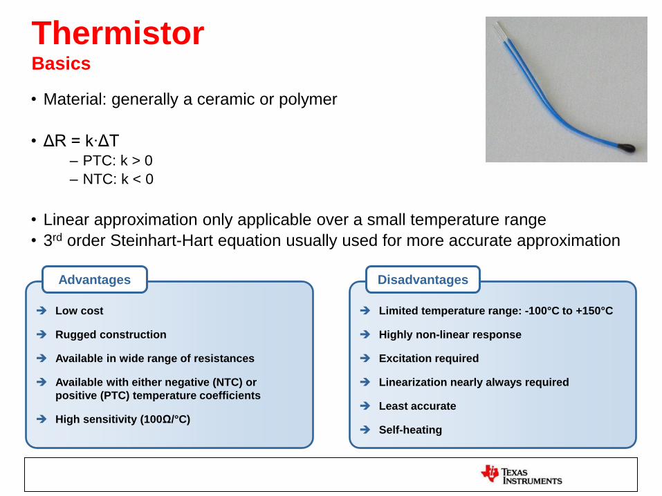
Thermistor Basics
• Material: generally a ceramic or polymer
• ΔR = k∙ΔT – PTC: k > 0
– NTC: k < 0
• Linear approximation only applicable over a small temperature range
• 3rd order Steinhart-Hart equation usually used for more accurate approximation
Low cost
Rugged construction
Available in wide range of resistances
Available with either negative (NTC) or
positive (PTC) temperature coefficients
High sensitivity (100Ω/°C)
Advantages
Limited temperature range: -100°C to +150°C
Highly non-linear response
Excitation required
Linearization nearly always required
Least accurate
Self-heating
Disadvantages

Thermistor Resistance vs. Temperature
Example of Glass Encapsulated Thermistor
R=10kΩ @ 25°C; Tolerance +/-0.2C from 0°C to 70°C
10kΩ @ 25°C
Graph obtained using Steinhart-Hart Equation: 1/T= A + B [Ln(R)] + C [Ln(R)]3
Omega Thermistor Model 55016: A=1.275x10⁻³; B=2.3441x10⁻⁴; C=8.6482x10⁻⁸
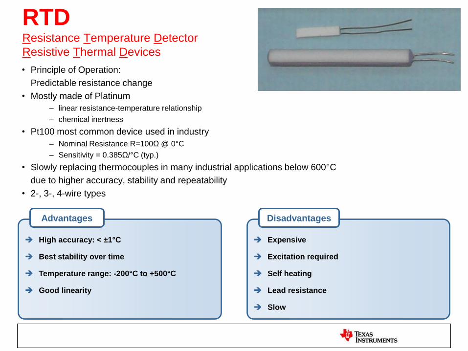
RTD Resistance Temperature Detector
Resistive Thermal Devices
• Principle of Operation:
Predictable resistance change
• Mostly made of Platinum
– linear resistance-temperature relationship
– chemical inertness
• Pt100 most common device used in industry
– Nominal Resistance R=100Ω @ 0°C
– Sensitivity = 0.385Ω/°C (typ.)
• Slowly replacing thermocouples in many industrial applications below 600°C
due to higher accuracy, stability and repeatability
• 2-, 3-, 4-wire types
High accuracy: < ±1°C
Best stability over time
Temperature range: -200°C to +500°C
Good linearity
Advantages
Expensive
Excitation required
Self heating
Lead resistance
Slow
Disadvantages

RTD/Thermistor Sensor Excitation
Current Source
Voltage Reference
REF200
Bridge Configuration
Shunt
REF5050 VDD
VShunt=IEX x RShunt RShunt

Thermocouple Basics
• Principle of Operation:
Thermoelectric / Seeback Effect
„Any conductor that is subjected to a thermal gradient
will generate a voltage between its ends”
• Consists of two dissimilar metal alloys.
Most common types:
– Chromel-Alumel (Type K)
– Iron-Constantan (Type J)
– Copper-Constantan (Type T)
Source: Omega Engineering

Thermocouple Basics
Wide temperature range (-200oC to +2000
oC)
Only contact temperature measurement
device for T >600oC
Self-powered
Very fast response, fractions of sec
Simple and durable in construction
Inexpensive
Wide variety of physical forms
Advantages
Thermocouple voltage non-linear with
temperature
Low measurement voltages (mV)
Lowest accuracy: ±2°C
Least stable and sensitive
Requires a known junction temperature
Disadvantages

Thermocouple Types
Type Type E Type K Type J Type R Type S Type T
Junction
Material
Nickel -10%
Chromium Vs
Constantan
Nickel -10%
Chromium Vs
Nickel -5%
Aluminum
Silicon
Iron Vs
Constantan
Platinum -
13%,
Rhodium Vs
Platinum (-)
Platinum -
10%,
Rhodium Vs
Platinum (-)
Copper Vs
Constantan
Seebeck
Coefficient
@20°C
62uV/°C 40uV/°C 62uV/°C 7uV/°C
7uV/°C 40uV/°C
Temperature
Range
-100 °C to
1000°C
0 °C to
1370°C
0 °C to
760°C
0 °C to
1450°C
0 °C to
1750°C
-160 °C to
400°C
General
Application
Cryogenic
use; non-
magnetic use
General
purpose
Higher
Sensitivity
High
Resistance to
oxidation and
corrosion,
calibration
purposes
Standard for
calibration for
the melting
point of gold
Often used in
differential
measurements
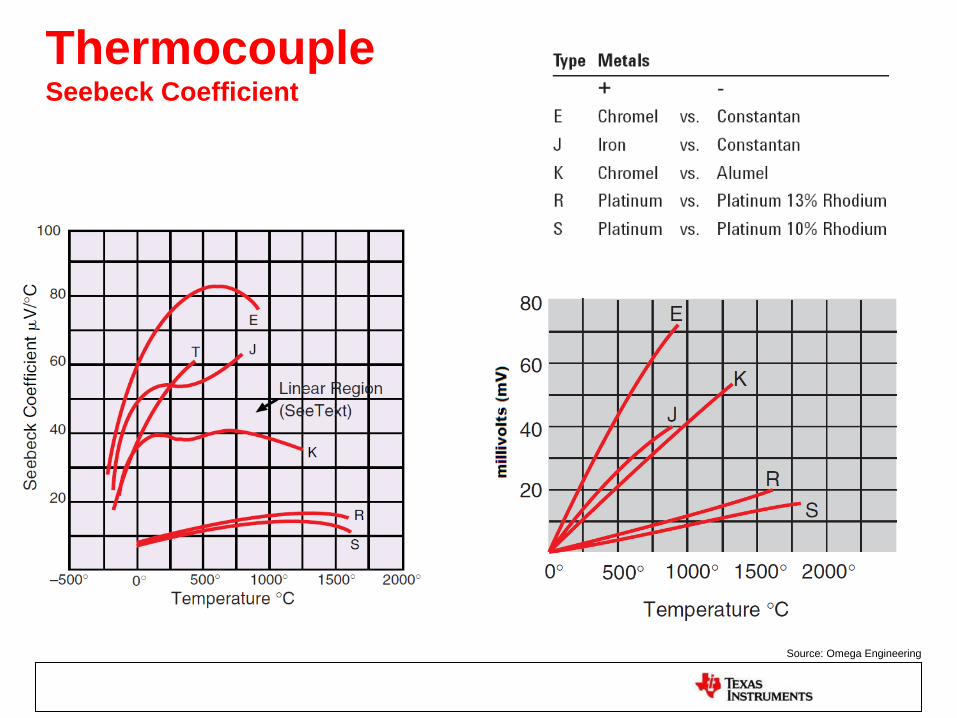
Thermocouple Seebeck Coefficient
Source: Omega Engineering

Thermocouple Cold Junction Compensation (CJC)


Thermocouple Temperature to Voltage Conversion
Source: Omega Engineering
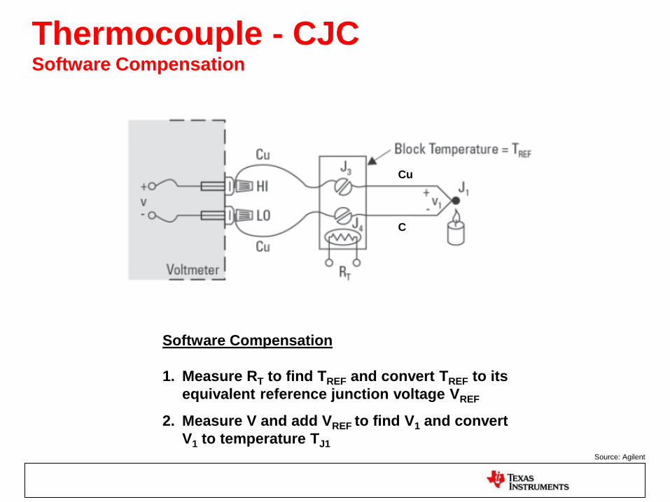
Thermocouple - CJC Software Compensation
Software Compensation
1. Measure RT to find TREF and convert TREF to its
equivalent reference junction voltage VREF
2. Measure V and add VREF to find V1 and convert
V1 to temperature TJ1 Source: Agilent
Cu
C

Thermocouples - CJC Example
• V = V1 - VREF
• Measure TREF using Temp Sensor:
TREF = 26°C
• Convert TREF to equivalent junction voltage
using look up table:
VREF = 1.329mV @ 26°C
• Measure V = 3.961mV with external meter
• Solve for V1:
V1 = V + VREF
V1= 3.961mV + 1.329mV = 5.269mV
• Convert V1 to TJ1 from table:
5.269mV corresponds to
TJ1 = 100°C

Summary
Source: Agilent

RTD Measurement
How to cope with lead resistance RLEAD
– 2-, 3-, 4-Wire RTD measurement
Absolute vs. ratiometric RTD measurement

Absolute 2-Wire Operation Using internal Reference
Main ADC
IDAC1
RTD
Int Ref Reference Mux
Input
Mux
RLEAD
RLEAD
AIN1
COM
IDAC2
Level Shift
Advantages:
+ Simplest implementation
+ Only one current source required
Disadvantages/Error Sources:
- Drift matching IDAC1 and int. Ref
- 2x RLEAD

Ratiometric 2-Wire Operation
Main ADC
IDAC1
RTD
RREF
Int Ref Reference Mux
Input
Mux
RLEAD
RLEAD
REFP
REFN
AIN1
COM
Advantages:
+ No drift mismatch between references
+ Drift and noise of reference cancel out
Disadvantages/Error Sources:
- 2x RLEAD
- Precision RREF required

Ratiometric 2-Wire Operation
Third order
ΔΣ modulatorPGA
- 1mV +
1 Ω
Line 1
1mA
+ 1mV -
+102mV
- Line 2
1 Ω
PT100R= 100Ω @ 0ºC
R= 139Ω @ 100ºC
+100mV
-
Input
MUX
ADS1248
1mA
Current
DAC
1mA
+ 1V -
REFP1 REFN1AVSS
Printed circuit
boardLines 1 & 2: model
250 ft. of 16 AWG
copper wire
RBIAS
1 KΩ
Vin 102mV
VRT D 100mV
Vin_span 139 100( ) 1 mA 0.039V
ErrorVin VRT D
Vin_span
100 5.128 %

Ratiometric 3-Wire Operation
Main ADC
IDAC1 IDAC2
RTD
RREF
Int Ref Reference Mux
Input
Mux
RLEAD
RLEAD
RLEAD
REFP
REFN
AIN1
COM
Advantages:
+ RLEAD compensation
Disadvantages/Error Sources:
- Drift matching IDAC1 and IDAC2
- Precision RREF required
- RLEAD need to match
AIN1 = IDAC1 (RLEAD + RTD + RLEAD + RREF)
COM = IDAC2 (RLEAD + RLEAD + RREF)
AIN1 – COM = IDAC1 ∙ RTD

Ratiometric 4-Wire Operation
Main ADC
IDAC1
RTD
RREF
Int Ref Reference Mux
Input
Mux
RLEAD
RLEAD
RLEAD
RLEAD
REFP
REFN
AIN2
AIN1
COM
Advantages:
+ Most accurate implementation
+ RLEAD compensation
+ RLEAD do not need to match
+ No drift mismatch between references
Disadvantages/Error Sources:
- Precision RREF required

ADS1248
A complete temperature sensing solution

Why use a ΔΣ- instead of SAR-Converter
• 50/60Hz line suppression
• Better noise performance for DC applications
• High resolution (up to 31Bit)
• No active anti-aliasing filter required
• Good for „slow“ signals
• Lower cost
• Lower power
• Small size
• Integration:
– PGA
– Current sources
– Sensor burn out detection
– Temp sensor

ADS1247, ADS1248 24-Bit, Complete Temperature Measurement ADC
EVM
• Ultimate Temperature Sensor Measurement Solution
• Most Flexible Front End for a Wide Range of Industrial Sensors
• High Integration Without Compromising Performance
• Scalable Solutions
Device Features:
• 2/4 Differential or 3/7 Single-Ended
• True Bipolar ±2.5V or Unipolar 5V
• Max Data Rate – 2kSPS
• Low Noise PGA: 40nV @ G = 128
• 50/60Hz Simultaneous Rejection Mode (20SPS)
On-Chip Integration:
• Low Drift Internal Reference (10 ppm/℃ Max)
• Dual Matched Current DACs (50 – 1500 μA)
• Oscillator, Temp Sensor, Burnout Detect
• 4/8 GPIO’s
• Temperature Management
• RTDs, Thermocouples, Thermistors
• Flow/Pressure Measurement
• Industrial Process Control
ADS1248EVM
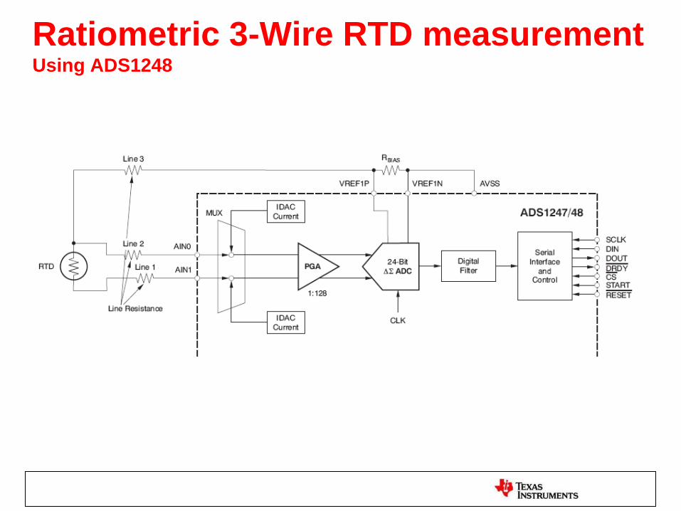
Ratiometric 3-Wire RTD measurement Using ADS1248

Ratiometric 3-Wire RTD measurement Hardware Compensation
RCOMP is chosen such that it is equal to the RTD resistance
at the middle of the temperature measurement range
Smaller input voltage range
Higher PGA Gain can be used
to make use of entire full sale range
Higher effective resolution
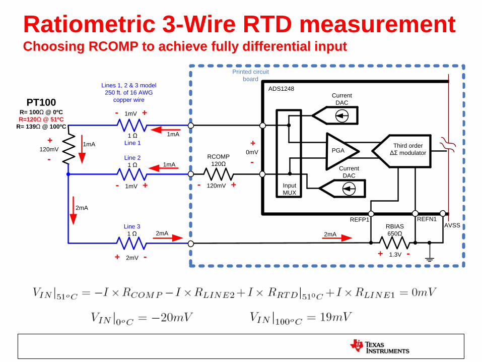
Ratiometric 3-Wire RTD measurement Choosing RCOMP to achieve fully differential input
Third order
ΔΣ modulatorPGA
- 1mV +
1 Ω
Line 1
1mA
+0mV
- Line 2
1 Ω
PT100R= 100Ω @ 0ºC
R=120Ω @ 51ºC
R= 139Ω @ 100ºC
+120mV
-
Input
MUX
ADS1248
1mA
Current
DAC
2mA
+ 1.3V -
REFP1 REFN1AVSS
Printed circuit
boardLines 1, 2 & 3 model
250 ft. of 16 AWG
copper wire
RBIAS
650Ω
Current
DAC
+ 2mV -
Line 3
1 Ω 2mA
2mA
- 1mV +
1mA
- 120mV +
RCOMP
120Ω

Eliminating IDAC mismatches Sample 1
Internal
Reference
Oscillator
Interface
and
Digital Filter
GPIO
CSn
DIN
SCLK
DRDYn
CLK DGND
AVDD VREFOUT VREFCOM
24 bit
ΔΣ
Modulator
1st order
PGA 24/16 bit
ΔΣ
Modulator
Vref Mux
REFP1 REFN1
Bias
Generator
System
Monitor
Self
Calibration
AVSS
DOUT/DRDYn
AVDD
START
RESETn
IEXC1 IEXC2 DVDD
RTD
• ADS1248 allows any configuration of IDAC on any channel
• IDACs can be used to implement a correlated double sampling of the inputs
• Kind of “chopping”

Eliminating IDAC mismatches Sample 2
Internal
Reference
Oscillator
Interface
and
Digital Filter
GPIO
CSn
DIN
SCLK
DRDYn
CLK DGND
AVDD VREFOUT VREFCOM
24 bit
ΔΣ
Modulator
1st order
24/16 bit
ΔΣ
Modulator
Vref Mux
REFP1 REFN1
Bias
Generator
System
Monitor
Self
Calibration
AVSS
DOUT/DRDYn
AVDD
START
RESETn
IEXC1 IEXC2 DVDD
RTD
PGA
0.5 x (Sample 1 + Sample 2)
mismatch-corrected result

Thermocouple Measurement

A common and important use of
thermocouples by engineers!

Thermocouple configuration 3-wire RTD used for CJC
Third order
ΔΣ modulatorPGA
Line 3
Line 4PT100
Input
MUX
ADS1248
Current
DACs
+ 1V -
REFP1 REFN1AVSS
Printed circuit
board
RBIAS
500ΩLine 5
VBIASLine 1
Line 2
Isothermal
block
K-typeRef. Junct. @ 0ºC
ΔV= 0mV @ 0ºC
ΔV= 4.096mV @ 100ºC
10μF
1μF
1μF1kΩ
1kΩ
15.9
Hz

ADS1118
Low Power Solution for Thermocouple
Measurements with CJC

ADS1118 World’s Smallest 16-bit ADC, 0.5°C (max) Accurate Temp Sensor
• Complete set of integrated functions:
• Four multiplexed analog inputs
• PGA (Gain: x0.33, x0.5, x1, x2, x4 or x8)
• Precision ADC with data rates from 8 to 860 SPS
• Internal temperature sensor (0.5°C max)
• Serial SPI Interface
• Small and versatile
• Low supply current: 150uA typ
• QFN 2.05mm x 1.55mm x 0.4mm
• Supply 2.0V – 5.5V
• Temperature Measurement
• Battery Pack
• Portable Instrumentation
• Industrial Process Control
• Gas Monitoring
• Embedded ADC Upgrade
CSn
DOUT/DRDYn
VDD
GND
SCLK
16-bit
ADC PGA
Oscillator
Internal Reference
M
U
X
Gains:
2/3,1,2,4,8,16
DIN
Temp Sensor
AINP1
AINP0
AINP3
AINP2
SPI
Interface
Tiny QFN(RUG) or MSOP(DGS) Package
• A single ADS1118 can perform data acquisition of
multiple signals from a wide variety of sensors.
• Small package that readily senses ambient
temperature to perform cold junction compensation
in thermocouple applications.
• Its size and low power consumption makes the
ADS1118 a great device for portable applications
where extended battery life is critical
ADS1118 EVM

Temperature Sensing IC Solutions
TMP102 TMP112 ADS1018 ADS1118
Resolution 0.0625 0.0625 0.125 0.03125
Max Error 2°C 0.5°C 1°C 0.5°C
Speed 40SPS 40SPS 3300SPS 860SPS
Size SOT-DRL
1.6x1.6x0.5
SOT-DRL
1.6x1.6x0.5
QFN-RUG
2x1.5x0.4mm
QFN-RUG
2x1.5x0.4mm
Power 23uW 23uW 500uW 500uW
uW/Conv 0.575uW/Conv 0.575uW/Conv
0.15uW/Conv 0.581uW/Conv
Interface I2C I2C SPI SPI
1k Price
$0.75 $0.85 $0.99 $2.25

ADS1118 Application Example with Thermocouples
- ADS1118 ideal low power solution for Thermocouples with reference junction
compensation
- Internal Temperature Sensor absolute accuracy is 0.5°C at 25°C
- Programmable Gain Amplifier (PGA) improves resolution
Temp Sensor for CJC
Cold (Reference) Junction Isothermal Block

ADS1118 Thermocouple measurement Input Impedance - Low Pass filter considerations
• Consider device input impedance
effect in measurement accuracy
• Keep resistor values of RC low
pass filters smaller than <5kΩ for
direct thermistor measurements
to prevent Linearity/Gain Errors
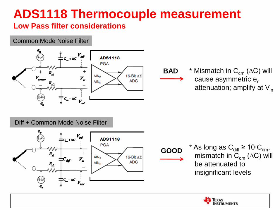
Common Mode Noise Filter
Diff + Common Mode Noise Filter
BAD * Mismatch in Ccm (∆C) will
cause asymmetric en
attenuation; amplify at Vin
GOOD * As long as Cdiff ≥ 10∙Ccm,
mismatch in Ccm (∆C) will
be attenuated to
insignificant levels
ADS1118 Thermocouple measurement Low Pass filter considerations

ADS1118 Thermocouple measurement Estimation of Accuracy/Resolution
Accuracy of
Thermocouple Accuracy of Reference Junction
Temperature Sensor
Accuracy/Resolution of ADC

ADS1118 Thermocouple measurement Estimation of Accuracy
• Example using K-type TC at 150°C Using FS ±0.256V;
LSB = (0.256V*2) / 216 = 7.81uV
Thermocouple Voltage at 150°C = 6.138mV
• Estimation of ADC voltage conversion absolute accuracy at 150°C:
Total Error = [(offset)2 + (gain error)2 + (INL)2 + (Noise)2]1/2
– Offset Error = ±3 LSB = ±23.43uV
– Gain Error = ±0.03%*6.138mV = ±1.84uV
– INL Error = ±1 LSB = ±7.81uV
– Noise @128SPS = 7.81uVp-p
– Gain Error due to RC Resistors = ±0.0037% * 6.138mV = ±0.227uV
• This yields an accuracy error = ±25.97uV or ±(25.97uV / 40uV/°C) = ±0.649°C
• Total Accuracy Error= [(IC Temp Sensor)2 + (ADC Error)2 +(Thermocouple Error)2]1/2
• Total Accuracy Error= [(0.5 °C)2 + (0.649°C)2 +(2.2°C)2]1/2
• Total Accuracy Error = ±2.34878°C @ 150°C

ADS1118 Thermocouple measurement Estimation of Resolution (°C/bit)
• Example using K-type TC
Using FS ±0.256V
• Calculation of ADC Resolution:
– Noise = ~8uVp-p @ ±0.256 FS, 128SPS
– SNR (dB) = 20*log10(Full-Scale / Noise)
– SNR (dB) = 20*log10((0.256*2 V) / 8uV) = 96.12dB
– SNR (dB) = 6.02 N + 1.76 where N = Noise Free Bits
– Noise Free Bits N = (96.12 – 1.76)/6.02 = 15.67
– Resolution (Volts) = 0.256 V *2 / 215.67 = 24.35uV
• Assuming Seebeck Coefficient of 40uV/°C for K-type
• Resolution = 24.35uV / 40 uV/°C = 0.244°C/bit (Noise Free)
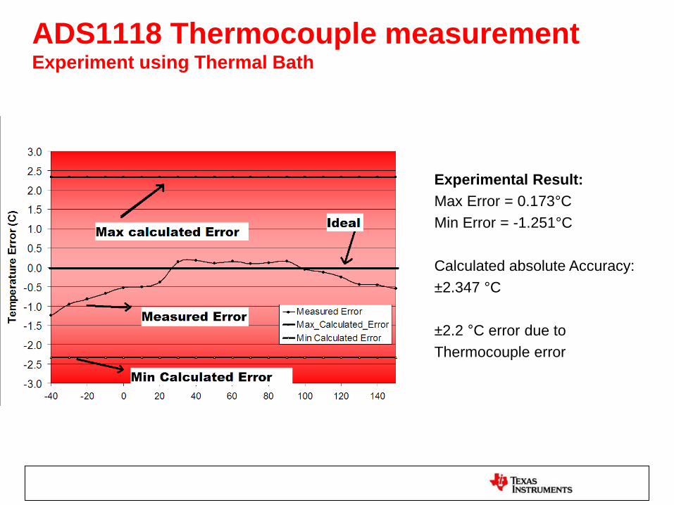
ADS1118 Thermocouple measurement Experiment using Thermal Bath
Experimental Result:
Max Error = 0.173°C
Min Error = -1.251°C
Calculated absolute Accuracy:
±2.347 °C
±2.2 °C error due to
Thermocouple error

ADS1115 and ADS1118 Power Savings Using Single-Shot Mode
Using single-shot mode results in great power savings on applications that
require only periodic conversions. Device automatically enters a low power
shut down after a conversion.
Continuous Mode
Single Shot Mode

ADS1115 and ADS1118 Power Savings Using Single-Shot Mode
Sampling
Rate
Mode Duty
Cycle
Power
Consumption
Total Samples
per Second
8 SPS Continuous Mode 100 % 300uW @ 2V Supply 8
32 SPS Single-Shot Mode 25 % 75uW @ 2V Supply 8
860 SPS Single-Shot Mode 1 % ~3uW @ 2V Supply
~8
128 SPS Continuous Mode 100 % 300uW @ 2V Supply 128
860 SPS
Single-Shot Mode 15 % 46uW @ 2V Supply 128
Using single-shot mode results in great power savings on applications that
require only periodic conversions. Device automatically enters a low power
shut down after a conversion.

ADS1118
Evaluationboard

ADS1118 EVM Demo Thermocouple Temperature Measurement
K-Type Temperature Measurement with
Reference Junction Compensation
K-Type Temperature Measurement
without Junction Compensation
Detected Cold Junction Temperature
with On-Board Temp Sensor
K-Type Temperature Measurement Constant at 25°C

Links
• Product Folders:
– ADS1248
http://www.ti.com/product/ads1248
– ADS1118
http://www.ti.com/product/ads1118
• Order samples and EVM’s:
– http://focus.ti.com/general/docs/buy.tsp?DCMP=TIHead
erTracking&HQS=Other+OT+hdr_b_buy