RTC-8070 - cranered.com · RTC– 8070 Upper Structure Boom Patented Design Boom side plates have...
19
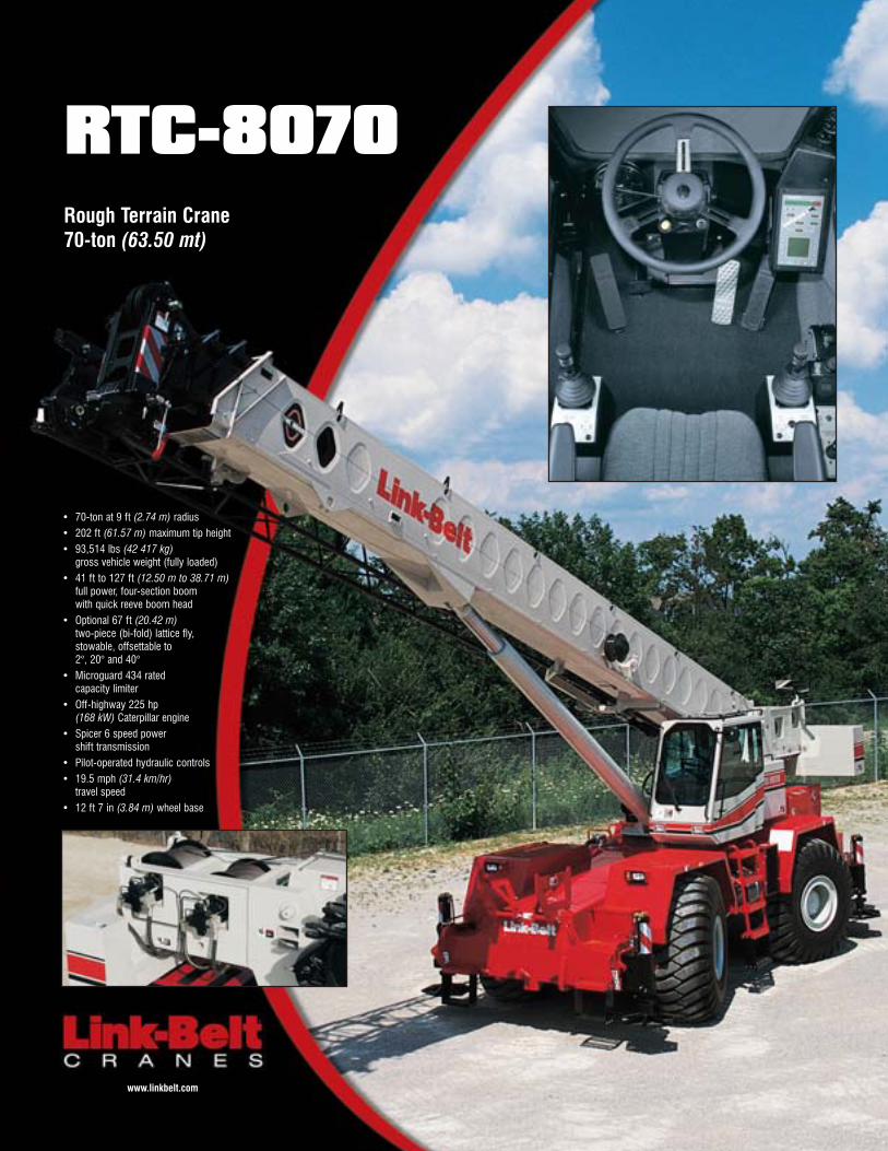
• 70-ton at 9 ft (2.74 m) radius • 202 ft (61.57 m) maximum tip height • 93,514 lbs (42 417 kg) gross vehicle weight (fully loaded) • 41 ft to 127 ft (12.50 m to 38.71 m) full power, four-section boom with quick reeve boom head • Optional 67 ft (20.42 m) two-piece (bi-fold) lattice fly, stowable, offsettable to 2°, 20° and 40° • Microguard 434 rated capacity limiter • Off-highway 225 hp (168 kW) Caterpillar engine • Spicer 6 speed power shift transmission • Pilot-operated hydraulic controls • 19.5 mph (31.4 km/hr) travel speed • 12 ft 7 in (3.84 m) wheel base RTC-8070 Rough Terrain Crane 70-ton (63.50 mt) www.linkbelt.com
-
Upload
truongkhue -
Category
Documents
-
view
216 -
download
0
Transcript of RTC-8070 - cranered.com · RTC– 8070 Upper Structure Boom Patented Design Boom side plates have...
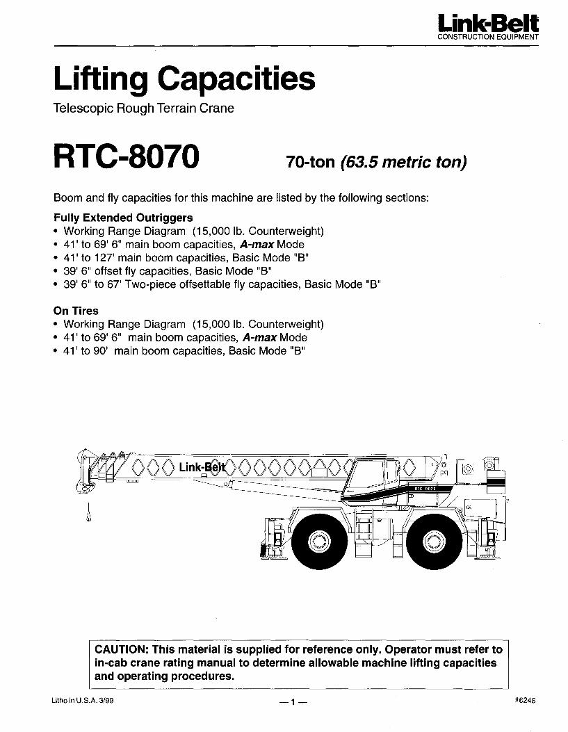
• 70-ton at 9 ft (2.74 m) radius• 202 ft (61.57 m) maximum tip height• 93,514 lbs (42 417 kg)
gross vehicle weight (fully loaded)• 41 ft to 127 ft (12.50 m to 38.71 m)
full power, four-section boomwith quick reeve boom head
• Optional 67 ft (20.42 m)two-piece (bi-fold) lattice fly,stowable, offsettable to2°, 20° and 40°
• Microguard 434 ratedcapacity limiter
• Off-highway 225 hp(168 kW) Caterpillar engine
• Spicer 6 speed powershift transmission
• Pilot-operated hydraulic controls• 19.5 mph (31.4 km/hr)
travel speed • 12 ft 7 in (3.84 m) wheel base
RTC-8070Rough Terrain Crane70-ton (63.50 mt)
www.linkbelt.com
Operator cab features• Large front window for excellent visibility• Tinted glass• Sliding right side and rear windows and
swing-up top window provide excellentventilation
• Integral rated capacity limiter aids theoperator in safe and efficient operation bycontinuously monitoring boom length, boomangle, head height, radius of load, machineconfiguration, allowed load and percent ofallowed load.
Powerful hydraulics• For greater productivity and control, the six-
pump hydraulic circuit allowssimultaneous function of boom hoist, winchand swing.
• Piston motor hydraulic hoist system deliverssuperior hoisting. Matched sizesof main and auxiliary winches provide equalmaximum available line pulls of 16,506 lbs(7 487 kg) and maximum line speeds of 454fpm (138 m/min) on 16" (.41 m) root diam-eter drums.
Job site maneuverability• Steering modes are chosen and performed
with the steering wheel and include inde-pendent front steer, four wheel steer, and"crab" steering.
• CALC — Outrigger beams have three liftingstages (retracted, intermediate and fullyextended) providing lifting capacities inconfined areas.
Invest in a legacyof outstandingcustomer support• Distributor support
personnel - Factory-trained technicians arespecifically tested toestablish proficiency inall aspects of cranediagnostics and repair.
• Factory product supportteam - Supporting yourtrained distributor per-sonnel are experiencedfactory advisors withcomprehensive records and technicallibraries that stand ready to resolve anycrane service issue.
• Parts Distribution Center - 72,000 sq. ft.Parts Distribution Center averages an over-90% parts availability rate.
• eParts - Link-Belt’s online computer systemlinks our distributors worldwide so cus-tomers can order genuine Link-Belt parts 24hours a day, 7 days a week.
• Link-Belt Preferred - Link-Belt’s customerweb site provides instant access to a com-prehensive library of all parts, service andoperator manuals plus other technical andsales information.
RTC-8070Rough Terrain Crane
Superiorperformance,control andreliability
The RTC-8070 isjam-packed with power,control & reliability !• Caterpillar 3126B electronic engine
with 225 hp (168 kW) provides 646 lb-ft(876 Nm) of torque
• Remote-mounted, thermostaticallycontrolled oil cooler provides maximumtransmission cooling under the mostextreme job site conditions
• Electronic throttle for improved throttleresponse
• Three automotive-style batteries linked inparallel and provide 700 cold cranking ampsfor cold weather starting
• Rugged, lightweight steel pontoons• Hydraulic disc brakes for both service
brakes and parking brake• Metri-Pak wire harnesses have sealed
relays and connectors throughout foroutstanding long-term reliability. All wireshave flame retardant polyethylene insulation,resulting in a higher heat resistant wiringsystem.
4-section full power boomwith attachment flexibility• Full power 41 ft to 127 ft (12.50 m to
38.71 m) four-section boom with twoextend modes: A-max and fullysynchronized
• Features the "Boss,"Link-Belt’s patentedboom design of highstrength angle cords andhigh formability sidewallembossments.
• Maximum tip height is 202 ft (61.57 m)with the attachment and main boom usedin combination
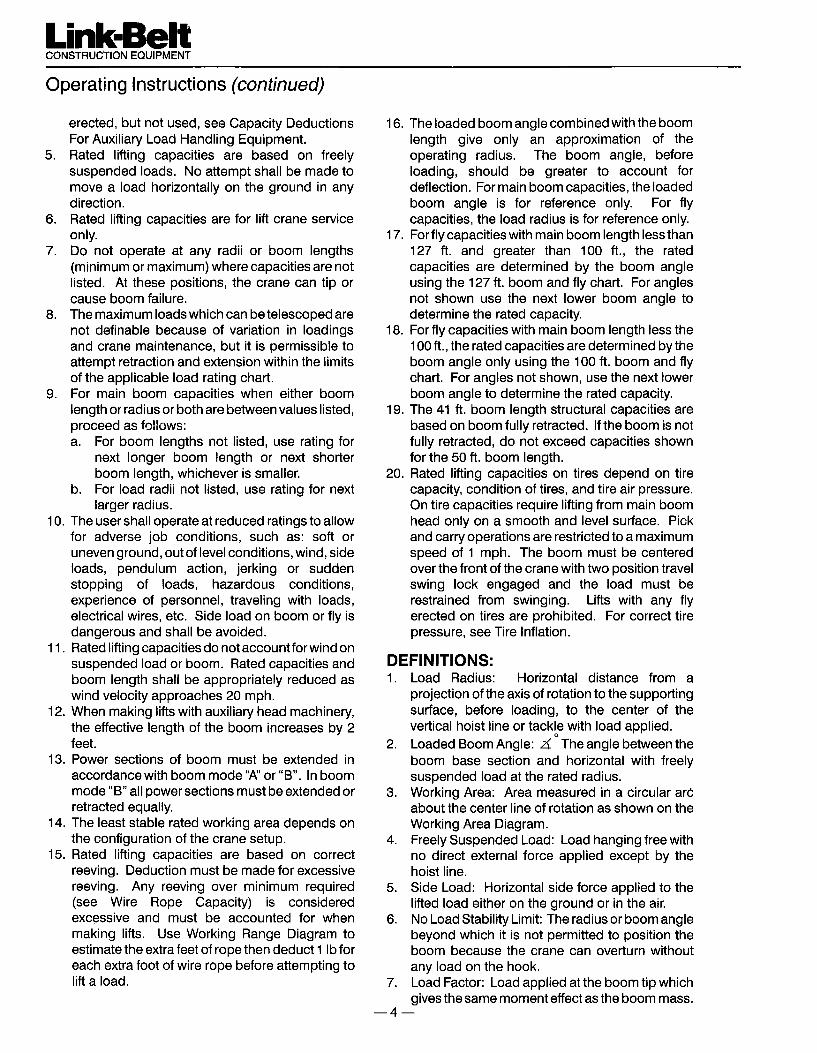
• Optional 39 ft 6 in (12.04 m) one-piecelattice fly and optional 39 ft 6 in to 67 ft(12.04 m to 20.42 m) two-piece bi-foldlattice fly are offsettable to 2°, 20° and 40°.
® Link-Belt is a registered trademark. Copyright 2003.All rights reserved. We are constantly improving ourproducts and therefore reserve the right to changedesigns and specifications.Litho in U.S.A. 12/03 #4284
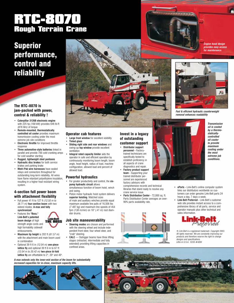
Engine hood designprovides easy accessfor maintenance.
Transmissionoil is cooledby a thermo-statically-controlledoil coolerto providemaximumcooling underthe mostextreme jobconditions.
Fast & efficient hydraulic counterweightremoval enhances roadability
A-max extends only the inner-mid section of the boom for substantiallyincreased capacities for in-close, maximum capacity lifts.
Litho in USA 10/03 #5398 Supersedes #5373
SpecificationsTelescopic Boom Rough Terrain Crane
RTC–8070 70–ton (63.50 metric tons)
C
3’ 3”(0.99 m)
FE
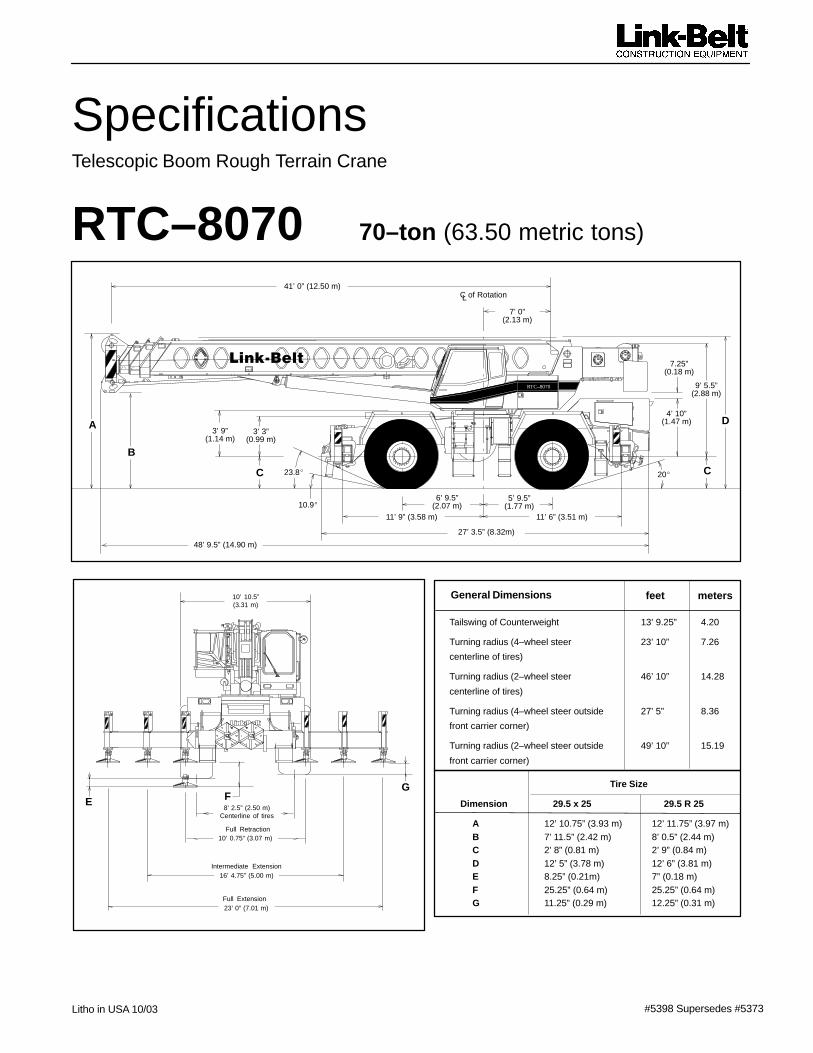
Tailswing of Counterweight 13’ 9.25” 4.20
Turning radius (4–wheel steer 23’ 10” 7.26
centerline of tires)
Turning radius (2–wheel steer 46’ 10” 14.28
centerline of tires)
Turning radius (4–wheel steer outside 27’ 5” 8.36
front carrier corner)
Turning radius (2–wheel steer outside 49’ 10” 15.19
front carrier corner)
C of RotationL
General Dimensions feet meters
41’ 0” (12.50 m)
7’ 0”(2.13 m)
23.8�
10.9�
20�
6’ 9.5”(2.07 m)
11’ 9” (3.58 m)
5’ 9.5”(1.77 m)
11’ 6” (3.51 m)
27’ 3.5” (8.32m)
4’ 10”(1.47 m)
10’ 0.75” (3.07 m)
8’ 2.5” (2.50 m)Centerline of tires
16’ 4.75” (5.00 m)
23’ 0” (7.01 m)
Tire Size
Dimension 29.5 x 25 29.5 R 25
A 12’ 10.75” (3.93 m) 12’ 11.75” (3.97 m)B 7’ 11.5” (2.42 m) 8’ 0.5” (2.44 m)C 2’ 8” (0.81 m) 2’ 9” (0.84 m)D 12’ 5” (3.78 m) 12’ 6” (3.81 m)E 8.25” (0.21m) 7” (0.18 m)F 25.25” (0.64 m) 25.25” (0.64 m)G 11.25” (0.29 m) 12.25” (0.31 m)
10’ 10.5”(3.31 m)
A
B
C
9’ 5.5”(2.88 m)
3’ 9”(1.14 m)
7.25”(0.18 m)
G
Full Retraction
Full Extension
Intermediate Extension
48’ 9.5” (14.90 m)
D
RTC–8070
��������
���RTC–8070
Upper Structure� BoomPatented Design� Boom side plates have diamond shaped
impressions for superior strength to weightratio and 100,000 psi (689.5 mPa) steelangle chords for lateral stiffness.
� Boom telescope sections are supported bytop, bottom, and adjustable side wearshoes to prevent metal to metal contact.
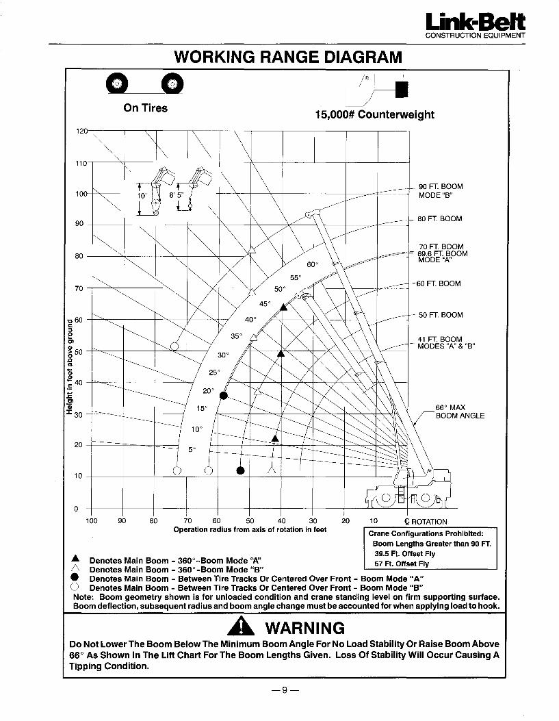
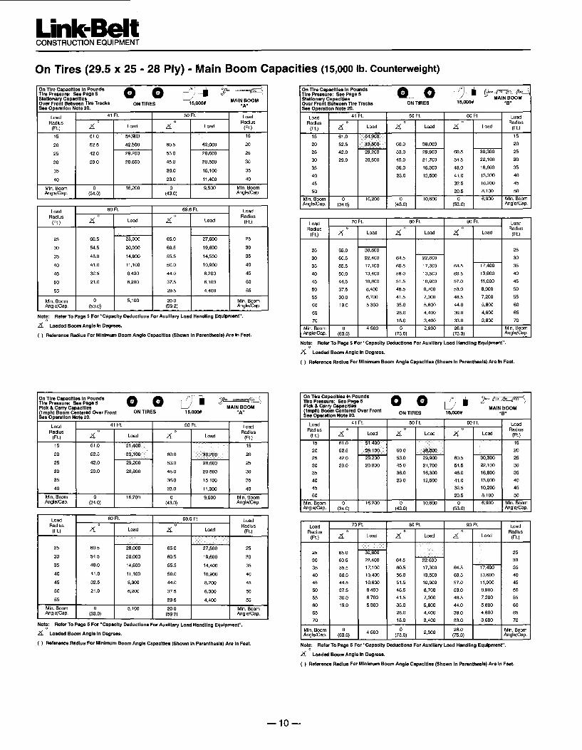
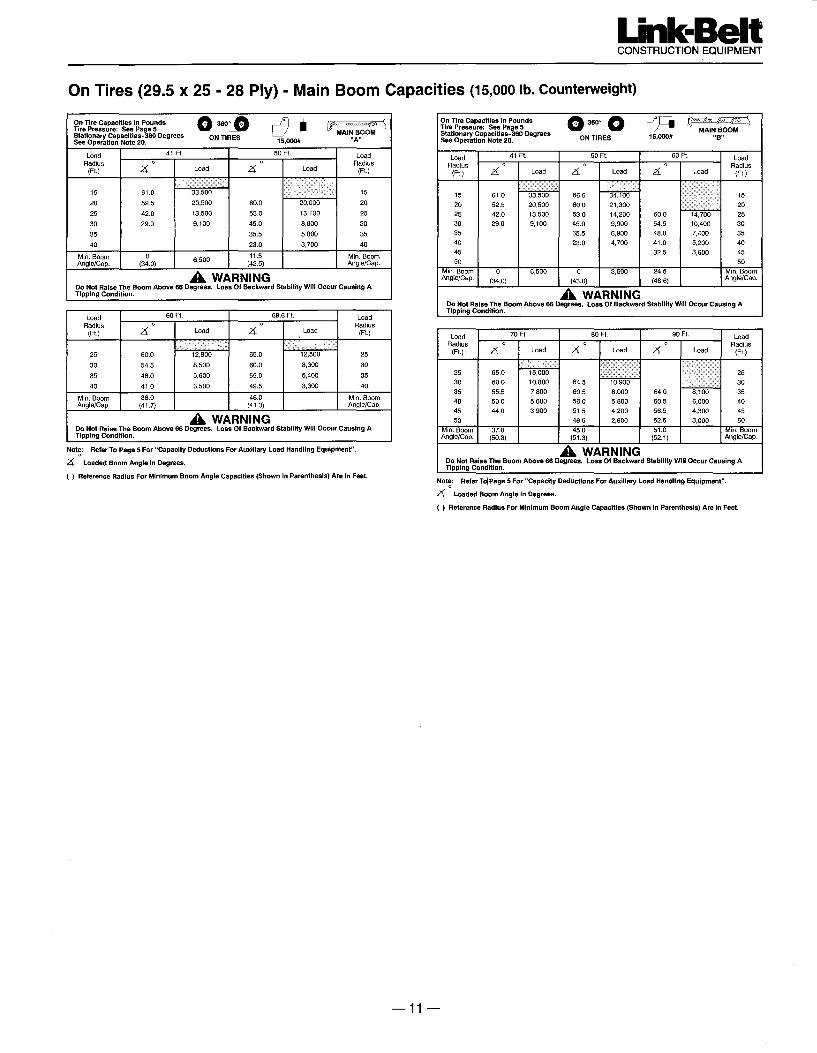
Standard Boom� 41’ – 127’ (12.50 – 38.71 m) four–section
full power boom.� Basic mode (or mode “B”) is the full
power, synchronized mode of telescop-ing all sections proportionally to 127’(38.71 m).
� The exclusive A–max mode (or mode“A”) extends only the inner mid–sectionto 69.5’ (21.18 m) offering increased ca-pacities for in–close, maximum capacitypicks.
� Mechanical Boom Angle IndicatorBoom Head� Five 16.5” (0.42 m) root diameter steel nylon
sheaves handle up to ten parts of wire rope.� Quick reeve design� Boom head designed for quick reeve of
hook block� Rope dead end lugs provided on each side
of boom head� Easily removable wire rope guards� Fly pinning alignment tool
Boom Elevation� Hydraulic cylinder with holding valves and
bushing in each end� Hand control for controlling boom
elevation from –3 to +78�Optional Auxiliary Lifting Sheave� Single 16.5” (0.42 m) root diameter steel
sheave with removable wire rope guardmounted on boom.
� Use with one or two parts of line.� Does not affect erection of fly or use of
main head sheaves for multiple reeving.Optional� 70–ton (63.5 mt) 5–sheave, quick reeve
hook block� 60–ton (54.43 mt) 4–sheave, quick reeve
hook block� 40–ton (36.28 mt) 4–sheave, quick reeve
hook block� 8.5–ton (7.7 mt) hook ball� Boom floodlight
� FlyOptional� 39.5’ (12.04 m) offsettable, stowable one–
piece lattice type with lugs to allow forsecond section. Can be offset 2�, 20�� or40��
� 39.5’ – 67’ (12.04 – 20.42 m) offsettable,stowable two–piece lattice type. Can beoffset 2�, 20�� or 40��
� Cab and ControlsEnvironmental Cab� LFC–2000 construction process featuring
laminated fibrous composite material.� Isolated from sound and vibration by a
neoprene seal� Six–way adjustable operator’s seat with
retractable seat belt� Four–way adjustable tilting and locking
steering wheel.� All windows are tinted and tempered
safety glass.� Slide by door opens to 3’ (0.91 m) width.� Sliding rear and right side windows and
swing up roof windows for maximum visibility and ventilation.
� Engine dependent warm–water heater withdefroster.
� Outrigger controls and sight level bubblealso provided in upper cab.
� Audible swing alarm. � Hand throttle� Backup alarm � Travel lights� Cab mounted work lights � Sun visor� Electric windshield wiper � Mirrors� Top hatch window wiper � Cup holder� Fire extinguisher � Circulating fan� Dome light � Warning horn
Optional� Amber strobe light and rotating beacon.� Emergency steering system� Air conditioning
ControlsHydraulic controls (joystick type) for:� Main winch � Boom hoist� Drum rotation indicators � Swing� Optional auxiliary winch.� Optional single–axis controls.
Foot controls for:� Boom telescope� Swing brake� Engine throttle with throttle lock
Cab InstrumentationCorner post mounted gauges for:� Hydraulic oil temperature� Convertor temperature� Audio/Visual warning system� Water temperature � ����� Tachometer � Voltmeter� Oil pressure
� Rated Capacity Limiter� Microguard 434 Graphic audio–visual
warning system built into dash with anti–two block and function limiters.
Operating data available includes:� Crane configuration� Boom length � Boom angle� Head height � Radius of load� Allowed load � Actual load� % of allowed load
Presettable alarms include:� Maximum and minimum boom angles.� Maximum tip height.� Maximum boom length.� Swing left/right positions.� Operator defined area alarm is standard.� Anti–two block weight designed for quick
reeve of hookblock.
Optional� Internal RCL light bar: Visually informs
operator when crane is approaching maxi-mum load capacity with a series of lights;green, yellow, and red.
� External RCL light bar: Visually informsground crew when crane is approachingmaximum load capacity kickouts and pre-settable alarms with a series of lights;green, yellow, and red.
� Swing� Bi–directional hydraulic swing motor
mounted to a planetary reducer for 360�continuous smooth swing at 2 r.p.m.
� Swing park brake – 360� electric overhydraulic (spring applied, hydraulic re-leased) multi–disc brake mounted on thespeed reducer. Operated by toggle switchin overhead control console.
� Swing brake – 360�, foot operated, hy-draulic applied disc brake mounted on thespeed reducer.
� Travel swing lock – Standard; two posi-tion travel lock (pin device) operated fromthe operator’s cab.
� Counterweight – Pinned to upper struc-ture frame. 15,000 lb (6 804 kg). Optional hydraulically controlled counter-weight removal.
Optional� 360� (pawl–in–gear) swing lock (meets
New York City requirements).
� Hydraulic SystemMain Pump� Four–section gear–type pump.� Combined pump capacity 132 gpm
(500 Lpm).� Mounted on torque converter, powered by
engine through a pump disconnect.� Pump disconnect is a spline type clutch
engaged/disengaged from carrier.� Pump operates at 3,500 psi (24.1 mPa)
maximum system pressure.� O–Ring Face Seal (ORFS) technology
throughout with hydraulic oil cooler.Pilot Pressure / Brake / CounterweightRemoval� Pressure compensated piston pump pow-
ered by carrier engine. Operates at 2,650psi (18.3 mPa) maximum.
Telescope/Outrigger/Steering Pump� Single gear–type pump, 24 gpm (91 Lpm)
maximum. Mounted on torque converter,powered by engine through a direct me-chanical drive.
� Pump operates at 3,000 psi (20.7 mPa)maximum system pressure.
Reservoir� 170 gal (643.5 L) capacity. Diffuser for
deaeration.Filtration� One, 10–micron filter located inside hy-
draulic reservoir. Accessible for easy re-placement.
RTC–8070–3–
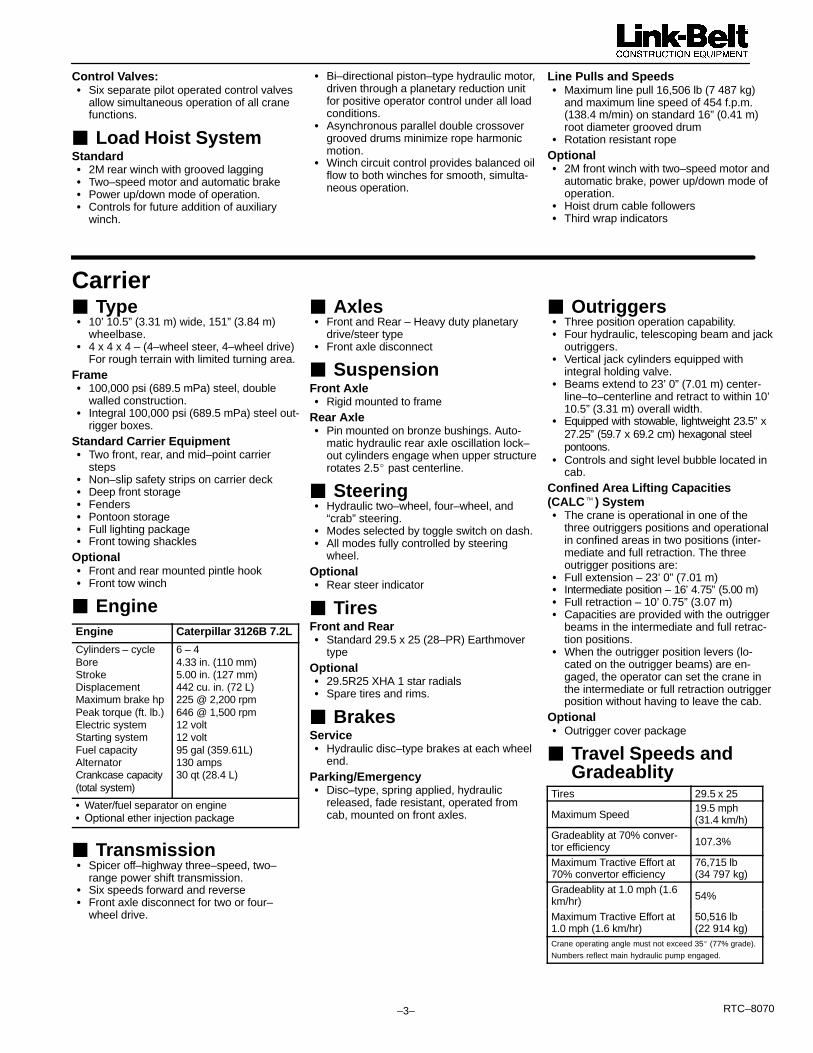
Control Valves:� Six separate pilot operated control valves
allow simultaneous operation of all cranefunctions.
� Load Hoist SystemStandard� 2M rear winch with grooved lagging� Two–speed motor and automatic brake� Power up/down mode of operation.� Controls for future addition of auxiliary
winch.
� Bi–directional piston–type hydraulic motor,driven through a planetary reduction unitfor positive operator control under all loadconditions.
� Asynchronous parallel double crossovergrooved drums minimize rope harmonic motion.
� Winch circuit control provides balanced oilflow to both winches for smooth, simulta-neous operation.
Line Pulls and Speeds� Maximum line pull 16,506 lb (7 487 kg)
and maximum line speed of 454 f.p.m.(138.4 m/min) on standard 16” (0.41 m)root diameter grooved drum
� Rotation resistant ropeOptional� 2M front winch with two–speed motor and
automatic brake, power up/down mode of operation.
� Hoist drum cable followers� Third wrap indicators
Carrier� Type� 10’ 10.5” (3.31 m) wide, 151” (3.84 m)
wheelbase.� 4 x 4 x 4 – (4–wheel steer, 4–wheel drive)
For rough terrain with limited turning area.Frame� 100,000 psi (689.5 mPa) steel, double
walled construction.� Integral 100,000 psi (689.5 mPa) steel out-
rigger boxes.Standard Carrier Equipment� Two front, rear, and mid–point carrier
steps� Non–slip safety strips on carrier deck� Deep front storage� Fenders� Pontoon storage� Full lighting package� Front towing shackles
Optional� Front and rear mounted pintle hook� Front tow winch
� EngineEngine Caterpillar 3126B 7.2L
Cylinders – cycleBoreStrokeDisplacementMaximum brake hpPeak torque (ft. lb.)Electric systemStarting systemFuel capacityAlternatorCrankcase capacity(total system)
6 – 44.33 in. (110 mm)5.00 in. (127 mm)442 cu. in. (72 L)225 @ 2,200 rpm646 @ 1,500 rpm12 volt12 volt95 gal (359.61L)130 amps30 qt (28.4 L)
� Water/fuel separator on engine� �� �����ther injection package
� Transmission� Spicer off–highway three–speed, two–
range power shift transmission.� Six speeds forward and reverse� Front axle disconnect for two or four–
wheel drive.
� Axles� Front and Rear – Heavy duty planetary
drive/steer type� Front axle disconnect
� SuspensionFront Axle� Rigid mounted to frame
Rear Axle� Pin mounted on bronze bushings. Auto-
matic hydraulic rear axle oscillation lock–out cylinders engage when upper structurerotates 2.5� past centerline.
� Steering� Hydraulic two–wheel, four–wheel, and
“crab” steering.� Modes selected by toggle switch on dash.� All modes fully controlled by steering
wheel.Optional� Rear steer indicator
� TiresFront and Rear� Standard 29.5 x 25 (28–PR) Earthmover
typeOptional� 29.5R25 XHA 1 star radials� Spare tires and rims.
� BrakesService� Hydraulic disc–type brakes at each wheel
end.Parking/Emergency� Disc–type, spring applied, hydraulic
released, fade resistant, operated fromcab, mounted on front axles.
� Outriggers� Three position operation capability.� Four hydraulic, telescoping beam and jack
outriggers.� Vertical jack cylinders equipped with
integral holding valve.� Beams extend to 23’ 0” (7.01 m) center-
line–to–centerline and retract to within 10’10.5” (3.31 m) overall width.
� Equipped with stowable, lightweight 23.5” x27.25” (59.7 x 69.2 cm) hexagonal steel pontoons.
� Controls and sight level bubble located incab.
Confined Area Lifting Capacities(CALC�) System� The crane is operational in one of the
three outriggers positions and operationalin confined areas in two positions (inter-mediate and full retraction. The three outrigger positions are:
� Full extension – 23’ 0” (7.01 m)� Intermediate position – 16’ 4.75” (5.00 m)� Full retraction – 10’ 0.75” (3.07 m)� Capacities are provided with the outrigger
beams in the intermediate and full retrac-tion positions.
� When the outrigger position levers (lo-cated on the outrigger beams) are en-gaged, the operator can set the crane inthe intermediate or full retraction outriggerposition without having to leave the cab.
Optional� Outrigger cover package
� Travel Speeds and Gradeablity
Tires 29.5 x 25
Maximum Speed19.5 mph (31.4 km/h)
Gradeablity at 70% conver-tor efficiency 107.3%
Maximum Tractive Effort at70% convertor efficiency
76,715 lb (34 797 kg)
Gradeablity at 1.0 mph (1.6km/hr) 54%
Maximum Tractive Effort at1.0 mph (1.6 km/hr)
50,516 lb (22 914 kg)
Crane operating angle must not exceed 35� (77% grade).
Numbers reflect main hydraulic pump engaged.
���RTC–8070
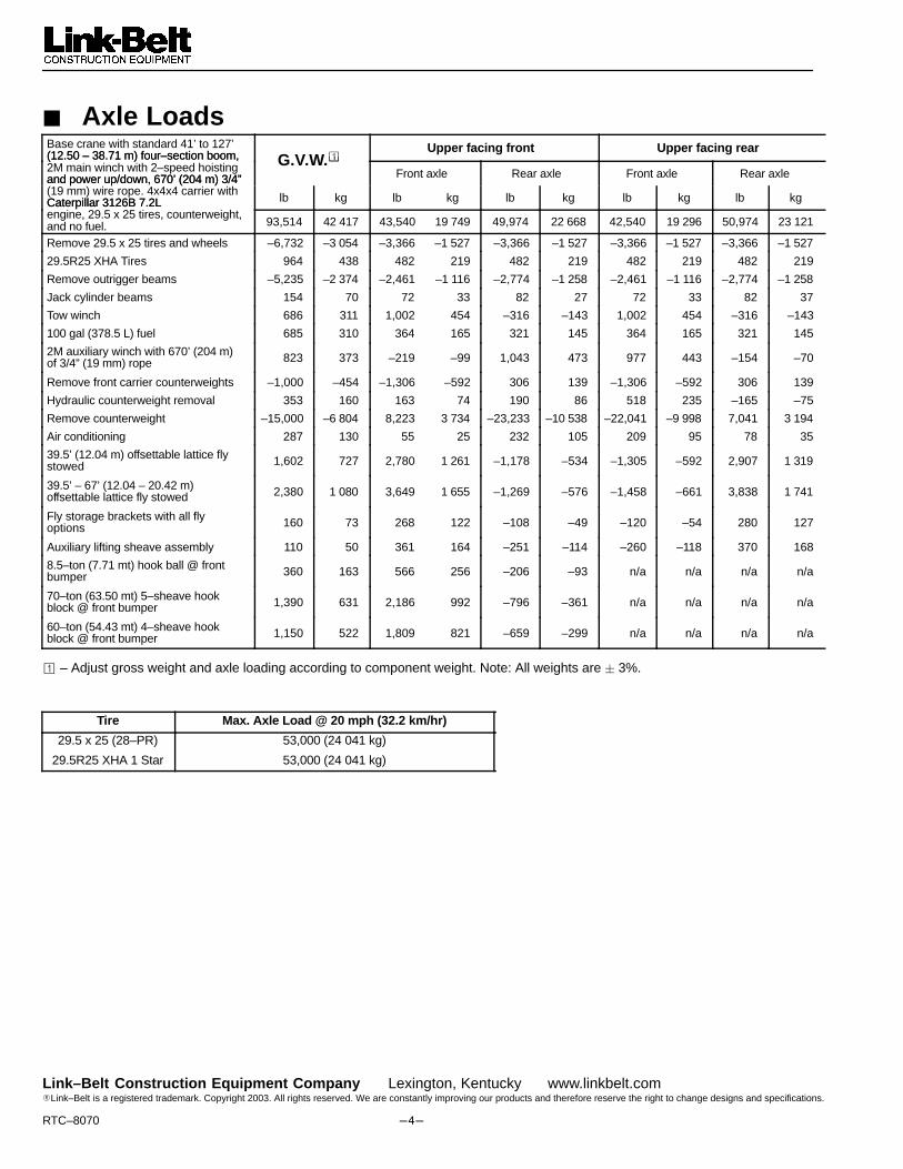
� Axle LoadsBase crane with standard 41’ to 127’(12.50 – 38.71 m) four–section boom, �
Upper facing front Upper facing rear(12.50 – 38.71 m) four–section boom,2M main winch with 2–speed hoistingand power up/down, 670’ (204 m) 3/4”
G.V.W.�Front axle Rear axle Front axle Rear axleand power up/down, 670’ (204 m) 3/4”
(19 mm) wire rope. 4x4x4 carrier withCaterpillar 3126B 7.2L lb kg lb kg lb kg lb kg lb kgCaterpillar 3126B 7.2L engine, 29.5 x 25 tires, counterweight,and no fuel. 93,514 42 417 43,540 19 749 49,974 22 668 42,540 19 296 50,974 23 121
Remove 29.5 x 25 tires and wheels –6,732 –3 054 –3,366 –1 527 –3,366 –1 527 –3,366 –1 527 –3,366 –1 527
29.5R25 XHA Tires 964 438 482 219 482 219 482 219 482 219
Remove outrigger beams –5,235 –2 374 –2,461 –1 116 –2,774 –1 258 –2,461 –1 116 –2,774 –1 258
Jack cylinder beams 154 70 72 33 82 27 72 33 82 37
Tow winch 686 311 1,002 454 –316 –143 1,002 454 –316 –143
100 gal (378.5 L) fuel 685 310 364 165 321 145 364 165 321 145
2M auxiliary winch with 670’ (204 m)of 3/4” (19 mm) rope 823 373 –219 –99 1,043 473 977 443 –154 –70
Remove front carrier counterweights –1,000 –454 –1,306 –592 306 139 –1,306 –592 306 139
Hydraulic counterweight removal 353 160 163 74 190 86 518 235 –165 –75
Remove counterweight –15,000 –6 804 8,223 3 734 –23,233 –10 538 –22,041 –9 998 7,041 3 194
Air conditioning 287 130 55 25 232 105 209 95 78 35
39.5’ (12.04 m) offsettable lattice flystowed 1,602 727 2,780 1 261 –1,178 –534 –1,305 –592 2,907 1 319
39.5’ – 67’ (12.04 – 20.42 m) offsettable lattice fly stowed 2,380 1 080 3,649 1 655 –1,269 –576 –1,458 –661 3,838 1 741
Fly storage brackets with all fly options 160 73 268 122 –108 –49 –120 –54 280 127
Auxiliary lifting sheave assembly 110 50 361 164 –251 –114 –260 –118 370 168
8.5–ton (7.71 mt) hook ball @ frontbumper 360 163 566 256 –206 –93 n/a n/a n/a n/a
70–ton (63.50 mt) 5–sheave hookblock @ front bumper 1,390 631 2,186 992 –796 –361 n/a n/a n/a n/a
60–ton (54.43 mt) 4–sheave hookblock @ front bumper 1,150 522 1,809 821 –659 –299 n/a n/a n/a n/a
� – Adjust gross weight and axle loading according to component weight. Note: All weights are � 3%.
Tire Max. Axle Load @ 20 mph (32.2 km/hr)
29.5 x 25 (28–PR)
29.5R25 XHA 1 Star
53,000 (24 041 kg)
53,000 (24 041 kg)
Link–Belt Construction Equipment Company Lexington, Kentucky www.linkbelt.com�Link–Belt is a registered trademark. Copyright 2003. All rights reserved. We are constantly improving our products and therefore reserve the right to change designs and specifications.


���RTC–8070
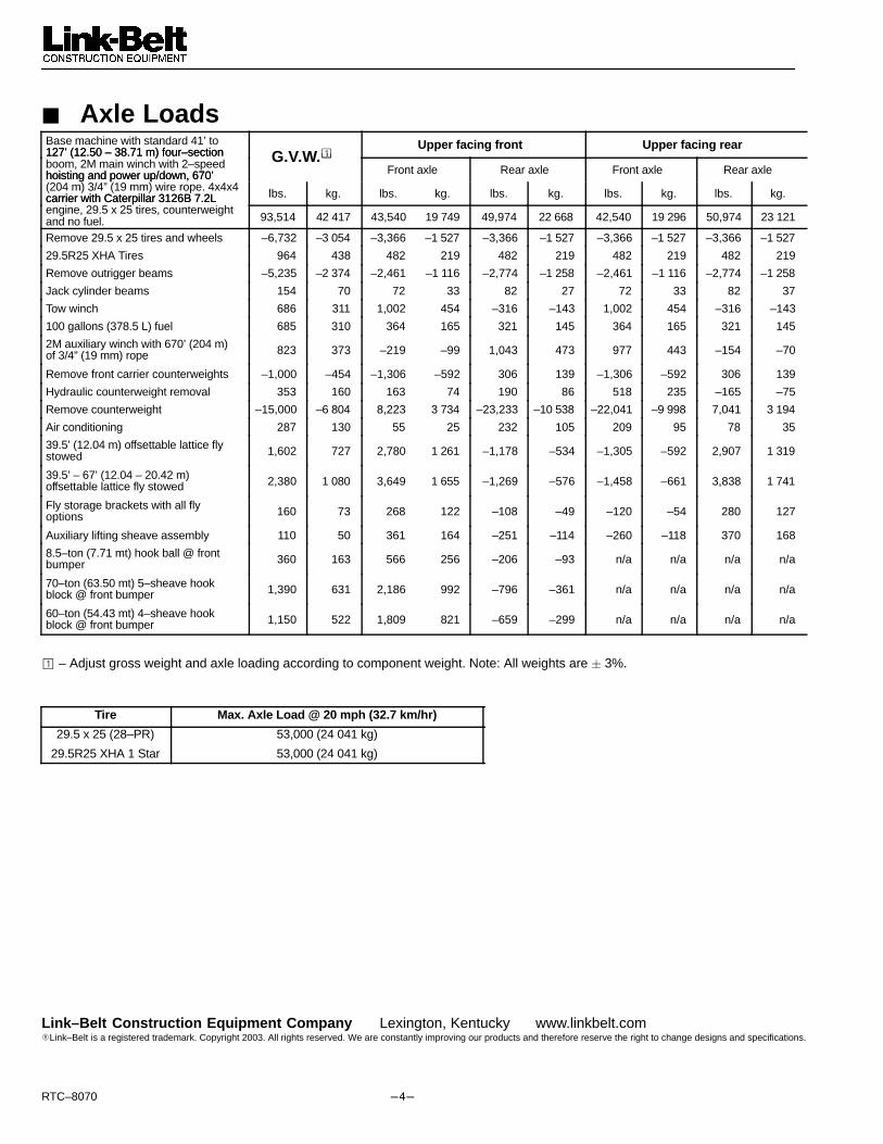
� Axle LoadsBase machine with standard 41’ to127’ (12.50 – 38.71 m) four–section �
Upper facing front Upper facing rear127’ (12.50 – 38.71 m) four–sectionboom, 2M main winch with 2–speedhoisting and power up/down, 670’
G.V.W.�Front axle Rear axle Front axle Rear axlehoisting and power up/down, 670’
(204 m) 3/4” (19 mm) wire rope. 4x4x4carrier with Caterpillar 3126B 7.2L lbs. kg. lbs. kg. lbs. kg. lbs. kg. lbs. kg.carrier with Caterpillar 3126B 7.2L engine, 29.5 x 25 tires, counterweightand no fuel. 93,514 42 417 43,540 19 749 49,974 22 668 42,540 19 296 50,974 23 121
Remove 29.5 x 25 tires and wheels –6,732 –3 054 –3,366 –1 527 –3,366 –1 527 –3,366 –1 527 –3,366 –1 527
29.5R25 XHA Tires 964 438 482 219 482 219 482 219 482 219
Remove outrigger beams –5,235 –2 374 –2,461 –1 116 –2,774 –1 258 –2,461 –1 116 –2,774 –1 258
Jack cylinder beams 154 70 72 33 82 27 72 33 82 37
Tow winch 686 311 1,002 454 –316 –143 1,002 454 –316 –143
100 gallons (378.5 L) fuel 685 310 364 165 321 145 364 165 321 145
2M auxiliary winch with 670’ (204 m)of 3/4” (19 mm) rope 823 373 –219 –99 1,043 473 977 443 –154 –70
Remove front carrier counterweights –1,000 –454 –1,306 –592 306 139 –1,306 –592 306 139
Hydraulic counterweight removal 353 160 163 74 190 86 518 235 –165 –75
Remove counterweight –15,000 –6 804 8,223 3 734 –23,233 –10 538 –22,041 –9 998 7,041 3 194
Air conditioning 287 130 55 25 232 105 209 95 78 35
39.5’ (12.04 m) offsettable lattice flystowed 1,602 727 2,780 1 261 –1,178 –534 –1,305 –592 2,907 1 319
39.5’ – 67’ (12.04 – 20.42 m) offsettable lattice fly stowed 2,380 1 080 3,649 1 655 –1,269 –576 –1,458 –661 3,838 1 741
Fly storage brackets with all fly options 160 73 268 122 –108 –49 –120 –54 280 127
Auxiliary lifting sheave assembly 110 50 361 164 –251 –114 –260 –118 370 168
8.5–ton (7.71 mt) hook ball @ frontbumper 360 163 566 256 –206 –93 n/a n/a n/a n/a
70–ton (63.50 mt) 5–sheave hookblock @ front bumper 1,390 631 2,186 992 –796 –361 n/a n/a n/a n/a
60–ton (54.43 mt) 4–sheave hookblock @ front bumper 1,150 522 1,809 821 –659 –299 n/a n/a n/a n/a
� – Adjust gross weight and axle loading according to component weight. Note: All weights are � 3%.
Tire Max. Axle Load @ 20 mph (32.7 km/hr)
29.5 x 25 (28–PR)
29.5R25 XHA 1 Star
53,000 (24 041 kg)
53,000 (24 041 kg)
Link–Belt Construction Equipment Company Lexington, Kentucky www.linkbelt.com�Link–Belt is a registered trademark. Copyright 2003. All rights reserved. We are constantly improving our products and therefore reserve the right to change designs and specifications.