Rt40 Danfoss radiator thermostats are manufactured in factories, assessed and certified by BSI...
6
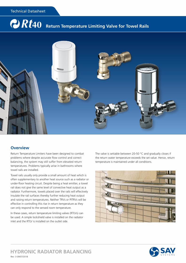
Technical Datasheet HYDRONIC RADIATOR BALANCING Rt 40 Rev: 3 09/07/2018 Overview Return Temperature Limiters have been designed to combat problems where despite accurate flow control and correct balancing, the system may still suffer from elevated return temperatures. Problems typically arise in bathrooms where towel rails are installed. Towel rails usually only provide a small amount of heat which is often supplementary to another heat source such as a radiator or under-floor heating circuit. Despite being a heat emitter, a towel rail does not give the same level of convective heat output as a radiator. Furthermore, towels placed over the rails will effectively insulate the rail surfaces thereby further reducing heat output and raising return temperatures. Neither TRVs or PITRVs will be effective in controlling this rise in return temperature as they can only respond to the sensed room temperature. In these cases, return temperature limiting valves (RTLVs) can be used. A simple lockshield valve is installed on the radiator inlet and the RTLV is installed on the outlet side. The valve is settable between 20-50 °C and gradually closes if the return water temperature exceeds the set value. Hence, return temperature is maintained under all conditions. Return Temperature Limiting Valve for Towel Rails
Transcript of Rt40 Danfoss radiator thermostats are manufactured in factories, assessed and certified by BSI...
Technical Datasheet
HYDRONIC RADIATOR BALANCING
Rt40
Rev: 3 09/07/2018
OverviewReturn Temperature Limiters have been designed to combat
problems where despite accurate flow control and correct
balancing, the system may still suffer from elevated return
temperatures. Problems typically arise in bathrooms where
towel rails are installed.
Towel rails usually only provide a small amount of heat which is
often supplementary to another heat source such as a radiator or
under-floor heating circuit. Despite being a heat emitter, a towel
rail does not give the same level of convective heat output as a
radiator. Furthermore, towels placed over the rails will effectively
insulate the rail surfaces thereby further reducing heat output
and raising return temperatures. Neither TRVs or PITRVs will be
effective in controlling this rise in return temperature as they
can only respond to the sensed room temperature.
In these cases, return temperature limiting valves (RTLVs) can
be used. A simple lockshield valve is installed on the radiator
inlet and the RTLV is installed on the outlet side.
The valve is settable between 20-50 °C and gradually closes if
the return water temperature exceeds the set value. Hence, return
temperature is maintained under all conditions.
Return Temperature Limiting Valve for Towel Rails

HYDRONIC RADIATOR BALANCING
Technical DatasheetTechnical Datasheet Rt40
OrderingReturn Temperature Limiting Valve for Towel Rails. Available in chrome or nickel finish.
Type Finish DescriptionTemp. range °C Xp = 2K
Rt40 AngleChrome 15 mm flow selectable angle valve body and thermostatic sensor.
15 mm fittings. Allen key for fixing sensor10 - 60
Nickel
Rt40 StraightChrome 15 mm flow selectable straight valve body, lockshield valve, thermostatic sensor.
15 mm fittings. Allen key for fixing sensor10 - 60
Nickel
Principle
Flow
Return
Flow
Return
All Danfoss radiator thermostats are manufactured in factories, assessed and certified by BSI (British Standard Institution)
against ISO 9000 and ISO 14001, and are approved to the European standard EN 215.
Quality
Technical Data
Thermostatic Sensor FinishMax Working Pressure (Bar)
Max Differential Pressure (Bar)
Test Pressure (Bar)
Max Water Temperature (ºC)
Return temperature limiter sensorAll white
10 0.6 16 120All chrome
Valve Body FinishKV Range at
XP = 0.5 - 2.0 KMax Working Pressure (Bar)
Max Differential Pressure (Bar)
Test Pressure (Bar)
Max Water Temperature (ºC)
Rt40 AngleChrome
0.55 10 0.6 16 120Nickel
Rt40 StraightChrome
0.55 10 0.6 16 120Nickel
Rt40 Angle Rt40 Straight
027

HYDRONIC RADIATOR BALANCING
Technical DatasheetTechnical Datasheet Rt40Valve Setting
Commissioning the valve
The Rt40 valve is unidirectional with a flow direction
selection feature.
• The Rt40 should be placed on the outlet (return) and the
lockshield valve should be installed on the inlet (flow).
• Establish the flow direction through the valve using these
diagrams, turning the setting ring as necessary to ensure
that water flow through the valve is always in the correct
direction and the risk of water hammer is eliminated.
SettingRt40 Lockshield Valve
Setting of max. water flow:
• Close the valve by means of a 6 mm Allen key
• Regulate the water flow by opening the valve
6 mm

HYDRONIC RADIATOR BALANCING
Technical DatasheetTechnical Datasheet Rt40Fitting the Sensor
1. Remove cap from valve and turn sensor to
2. Press the sensor firmly onto the valve.
Sensor horizontal: ensuring that the scale pointer is at top.
Sensor vertical: ensuring that the scale pointer is at the front.
3. Whilst holding the sensor firmly on the valve secure
connection by tightening the Allen screw using the
enclosed key.
4. Set desired room temperature.
Removing the Sensor Loosen the Allen screw (3). The sensor can now be separated
from the valve.
Sensor
Pressure pin
Gland seal
Revolver setting knob
Spindle
Bi-directional valve cone
Revolver
Valve body
Design - Rt40Valve bodies are manufactured from brass with chrome
or nickel plating. The spindle in the gland seal is of
chrominium steel and works in a lifetime lubricated
o-ring. The complete gland assembly can be replaced
without draining down the system.
Materials in contact with water
Valve body and other metal parts Brass
Valve body surface Nickel/Chrome plated
Flow-limiter PPS
O-ring EPDM
Valve cone NBR
Pressure pin and spring Chrome steel
Regulator Brass/EPDM
HYDRONIC RADIATOR BALANCING
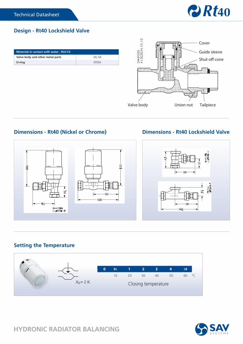
Technical DatasheetTechnical Datasheet Rt40Design - Rt40 Lockshield Valve
Materials in contact with water - RLV-CX
Valve body and other metal parts Ms 58
O-ring EPDM
Rt401. Gland seal2. O-Ring3. Pressure pin4. Seal5. Regulation spring6. Setting dial7. Valve body8. kv-nozzle
Cover
Guide sleeve
Shut-o� cone
Valve body Union nut Tailpiece
Dimensions - Rt40 (Nickel or Chrome) Dimensions - Rt40 Lockshield Valve
10 20 30 40 50 60 °C
0 I< 1 2 3 4 >I
Closing temperature
Setting the Temperature
SAV (UK) Limited, Scandia House, Boundary Road, Woking, Surrey GU21 5BX
Phone: 01483 771910 Email: [email protected]
Web: www.sav-systems.com LinkedIn: www.linkedin.com/company/sav-systems
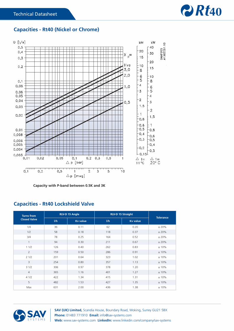
Technical DatasheetTechnical Datasheet Rt40Capacities - Rt40 (Nickel or Chrome)
Capacities - Rt40 Lockshield Valve
Capacity with P-band between 0.5K and 3K
Turns from Closed Valve
RLV-D 15 Angle RLV-D 15 Straight Tolerance
l/h Kv value l/h Kv value
1/4 36 0.11 62 0.20 ± 20%
1/2 58 0.18 118 0.37 ± 20%
3/4 78 0.25 164 0.52 ± 20%
1 94 0.30 211 0.67 ± 20%
1 1/2 126 0.40 262 0.83 ± 10%
2 159 0.50 286 0.91 ± 10%
2 1/2 201 0.64 323 1.02 ± 10%
3 254 0.80 357 1.13 ± 10%
3 1/2 306 0.97 378 1.20 ± 10%
4 365 1.16 401 1.27 ± 10%
4 1/2 422 1.34 415 1.31 ± 10%
5 482 1.53 427 1.35 ± 10%
Max 631 2.00 436 1.38 ± 10%