RT Space Elevator Space Debris 22June 10...Space Elevator Survivability – Space Debris Mitigation...
45
DRAFT i Space Elevator Survivability – Space Debris Mitigation Draft 22 June 2010 International Space Elevator Consortium Fall 2010 Notice: This is a draft version of the document for use as a starting place for discussion. All aspects of the study report are open to suggested changes and will incorporate inputs from study team members as appropriate. When finished, the Board of Directors will approve or disapprove the document as an International Space Elevator Consortium position paper called, Red Team Study. Red Team Study Peter Swan Robert “Skip” Penny Cathy Swan A Pamphlet for Progress in Space Elevator Technology Draft Schedule: Draft to website key ISEC players 1 June 2010 Public release on Conference website 15 June 2010 Comments to Dr. Swan [[email protected] ] thru 14 Aug 2010 Comment Consolidation by 15 Aug Final Draft Version to ISEC Leadership 1 Sept 2010 Publishing book 15 Nov 2010
Transcript of RT Space Elevator Space Debris 22June 10...Space Elevator Survivability – Space Debris Mitigation...
DRAFT
i
Space Elevator Survivability –
Space Debris Mitigation
Draft 22 June 2010
International Space Elevator Consortium Fall 2010
Notice: This is a draft version of the document for use as a starting place for discussion. All aspects of the study report are open to suggested changes and will incorporate inputs from study team members as appropriate. When finished, the Board of Directors will approve or
disapprove the document as an International Space Elevator Consortium position paper called, Red Team Study.
Red Team Study
Peter Swan Robert “Skip” Penny
Cathy Swan
A Pamphlet for Progress in Space Elevator Technology
Draft Schedule: Draft to website key ISEC players 1 June 2010 Public release on Conference website 15 June 2010 Comments to Dr. Swan [[email protected] ] thru 14 Aug 2010 Comment Consolidation by 15 Aug Final Draft Version to ISEC Leadership 1 Sept 2010 Publishing book 15 Nov 2010
DRAFT
ii
International Space Elevator Consortium Mission Statement: "... ISEC promotes the development, construction and operation of a space elevator as a revolutionary and efficient way to space for all humanity ..." Mr. Ted Semons (United States), is president of the International Space Elevator Consortium. The organization of the ISEC is based upon four pillars: Technology, Law, Business, and Outreach. Each of the pillars is headed by a pillar lead, who functions much like a university's department head. Their job is to start initiatives (projects), pursue collaborations, guide project leads and prospective project leads in pursuing their individual projects, and generally increase the activity level of their pillar. Four Pillars: · Technical: Investigates the technical aspects of the space elevator and its development, from the material development, to the ribbon riders design and the power approach for the system. This pillar leads all efforts to understand, encourage development of necessary technologies, facility designs and “real world” testing of key elements of the system of systems. · Business: Currently developing a business-case study, justifying the cost of a Space Elevator. With the baseline of the GEO satellite market, the future funding flows must be shown as larger than the cost of the system. · Legal: International Space Law will dominant the legal side of the project and is being investigated in multiple ways at the present time. · Public Relations: A new Press Kit should be available soon. Please visit the ISEC website: www.isec.info
Notice: This Red Team Study, or position paper, is intended to be approved by the Board of Directors of the International Space Elevator Consortium (ISEC). Any opinion, findings and conclusions or recommendations expressed in this report are those of the ISEC and do not necessarily reflect the views of the sponsoring or funding organizations. For more information about the International Space Elevator Consortium, visit the home pages at www.isec.info. Copyright 2010 by the International Space Elevator Consortium. All rights reserved.

DRAFT
iii
Executive Summary
DRAFT
iv
Space Elevator Survivability – Space Debris Mitigation Detailed Outline: Page # Executive Summary Preface Introduction What is a Space Elevator Survivability Areas Definition of the Problem: Space Debris, now and the future History of Space Debris December Conference Space Debris Characterization Regional characterization Probability of Impact Calculation Approach Probability Analysis GEO MEO LEO Beyond GEO Summation of Space Debris Problem
Mitigation Techniques Policy Design Movement Removal
Conclusions: Recommendations For the Space Community For the Space Elevator Community Projections into the Future Appendix References Document to be placed on the ISEC website in final draft mode and invite comments to be presente by “experts” who attend the conference in august.

DRAFT
v
Preface Written by Ted Semons – President of ISEC [don’t worry Ted, I’ll help draft after we write it]

DRAFT
vi
DRAFT
1
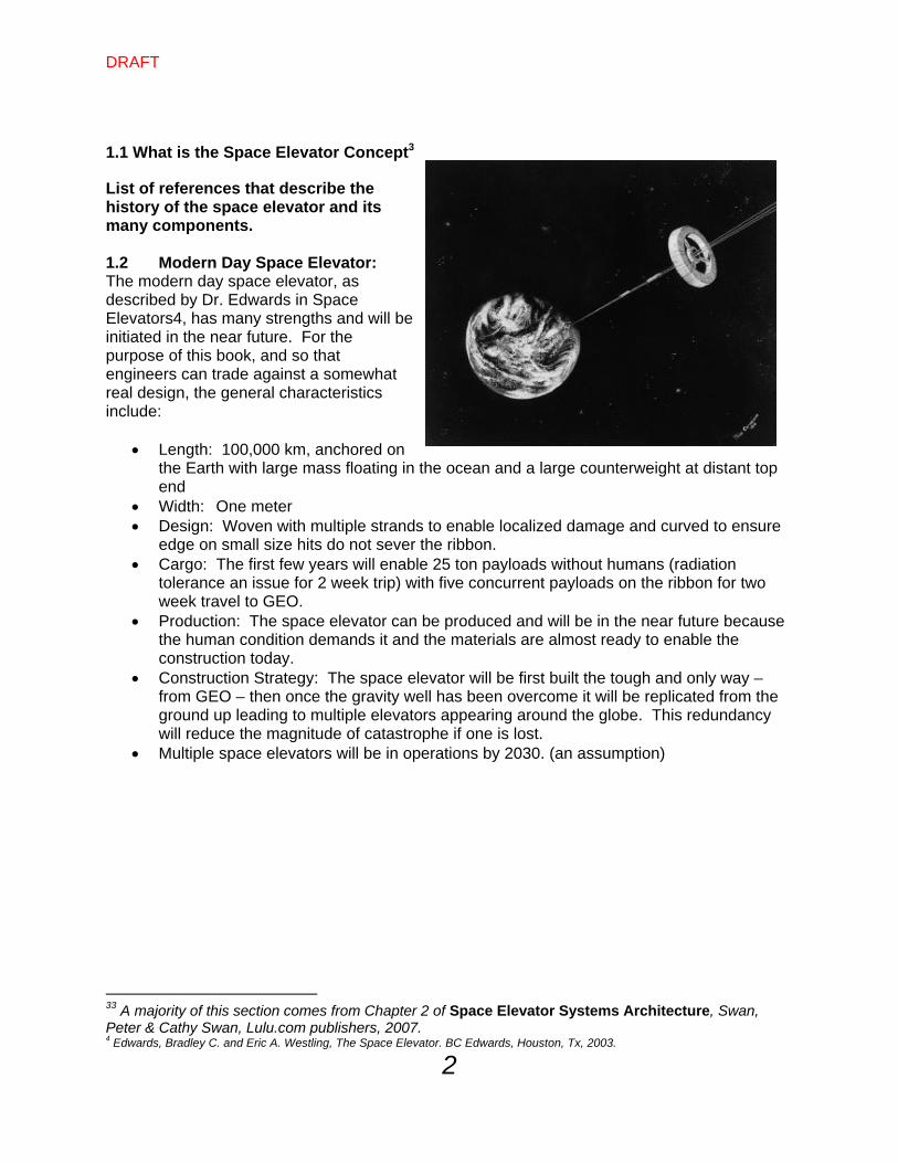
Chapter 1 – Introduction 1.0 General Background: Space debris will pose a hazard to a 100,000 km long, one meter wide space elevator. To establish a space elevator program, the issue of space debris must be addressed through the establishment of requirements for the knowledge of the debris location and the propagation of that knowledge into the future. Derivative requirements such as space elevator segment location, response time, and anchor platform maneuverability must also be addressed. This pamphlet will address the risk of debris to a space elevator, present potential mitigation measures, and make recommendations with respect to the space elevator and the space debris environment. The modern day space elevator, as described by Dr. Edwards in Space Elevators1, has many strengths and will be accomplished in the near future; however, the understanding of the environment in which it will live is paramount to a successful operation. As outlined in Space Elevator Systems Architecture2, there are many threats to the space elevator; however, for each threat there are many engineering mitigation techniques. This pamphlet will address one such threat, describe the magnitude of concern, and then suggest mitigation techniques. When considering space debris and its threat to the Space Elevators, some questions that have to be asked are:
How precisely does one need to know the location of the space elevator ribbon segments?
How precisely does one have to know the location, and propagated location of large space debris?
What are the projected levels of concern and what needs to be accomplished prior to operations?
How do we mitigate the risk of orbiting debris and satellites colliding with the space elevator?
What is the probability of puncture from impacts of small items? What is the probability of sever by large orbiting objects? How should the space elevator community plan to mitigate these threats?
This effort will discuss multiple altitude regions, ranging from LEO, where the greatest
hazards exists, to beyond GEO, where micrometeoroids are the primary threat. Research should address three debris threat categories: (a) small [less than 10 cm) which are numerous with random direction, (b) tracked and inert (10 cm and larger) with known numbers and orbital characteristics, and (c) large and controllable (active satellites are about 6% of tracked objects).
1 Edwards, Bradley C. and Eric A. Westling, The Space Elevator. BC Edwards, Houston, Tx, 2003. 2 Swan, Peter A. and Cathy W. Swan, Space Elevator Systems Architecture, Lulu.com, 2007.
DRAFT
2
1.1 What is the Space Elevator Concept3
List of references that describe the history of the space elevator and its many components. 1.2 Modern Day Space Elevator: The modern day space elevator, as described by Dr. Edwards in Space Elevators4, has many strengths and will be initiated in the near future. For the purpose of this book, and so that engineers can trade against a somewhat real design, the general characteristics include:
Length: 100,000 km, anchored on the Earth with large mass floating in the ocean and a large counterweight at distant top end
Width: One meter Design: Woven with multiple strands to enable localized damage and curved to ensure
edge on small size hits do not sever the ribbon. Cargo: The first few years will enable 25 ton payloads without humans (radiation
tolerance an issue for 2 week trip) with five concurrent payloads on the ribbon for two week travel to GEO.
Production: The space elevator can be produced and will be in the near future because the human condition demands it and the materials are almost ready to enable the construction today.
Construction Strategy: The space elevator will be first built the tough and only way – from GEO – then once the gravity well has been overcome it will be replicated from the ground up leading to multiple elevators appearing around the globe. This redundancy will reduce the magnitude of catastrophe if one is lost.
Multiple space elevators will be in operations by 2030. (an assumption)
33 A majority of this section comes from Chapter 2 of Space Elevator Systems Architecture, Swan, Peter & Cathy Swan, Lulu.com publishers, 2007. 4 Edwards, Bradley C. and Eric A. Westling, The Space Elevator. BC Edwards, Houston, Tx, 2003.
DRAFT
3
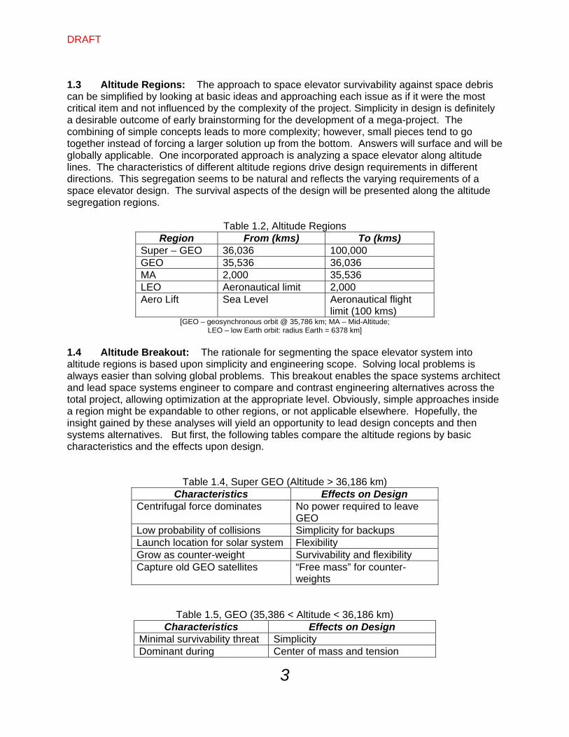
1.3 Altitude Regions: The approach to space elevator survivability against space debris can be simplified by looking at basic ideas and approaching each issue as if it were the most critical item and not influenced by the complexity of the project. Simplicity in design is definitely a desirable outcome of early brainstorming for the development of a mega-project. The combining of simple concepts leads to more complexity; however, small pieces tend to go together instead of forcing a larger solution up from the bottom. Answers will surface and will be globally applicable. One incorporated approach is analyzing a space elevator along altitude lines. The characteristics of different altitude regions drive design requirements in different directions. This segregation seems to be natural and reflects the varying requirements of a space elevator design. The survival aspects of the design will be presented along the altitude segregation regions.
Table 1.2, Altitude Regions Region From (kms) To (kms)
Super – GEO 36,036 100,000 GEO 35,536 36,036 MA 2,000 35,536 LEO Aeronautical limit 2,000 Aero Lift Sea Level Aeronautical flight
limit (100 kms) [GEO – geosynchronous orbit @ 35,786 km; MA – Mid-Altitude;
LEO – low Earth orbit: radius Earth = 6378 km]
1.4 Altitude Breakout: The rationale for segmenting the space elevator system into altitude regions is based upon simplicity and engineering scope. Solving local problems is always easier than solving global problems. This breakout enables the space systems architect and lead space systems engineer to compare and contrast engineering alternatives across the total project, allowing optimization at the appropriate level. Obviously, simple approaches inside a region might be expandable to other regions, or not applicable elsewhere. Hopefully, the insight gained by these analyses will yield an opportunity to lead design concepts and then systems alternatives. But first, the following tables compare the altitude regions by basic characteristics and the effects upon design.
Table 1.4, Super GEO (Altitude > 36,186 km) Characteristics Effects on Design
Centrifugal force dominates No power required to leave GEO
Low probability of collisions Simplicity for backups Launch location for solar system Flexibility Grow as counter-weight Survivability and flexibility Capture old GEO satellites “Free mass” for counter-
weights
Table 1.5, GEO (35,386 < Altitude < 36,186 km) Characteristics Effects on Design
Minimal survivability threat Simplicity Dominant during Center of mass and tension
DRAFT
4
developmental phase measurements Critical transportation node Work station (with or without
people) GEO node attach-detach as climbers pass altitude
Understanding of local dynamics and robotic grappling
Maybe GEO node not attached to space elevator – just floats along side
Creative design option needs to be traded
Table 1.6, Mid-Altitude (2,000 < Altitude < 35,386 km) Characteristics Effects on Design
Self deploy Minimum design LEO/MEO satellite nodes Launch and inclination issues Real debris issues (Molniya, GEO Transfer Orbit, Navigation orbits)
Survivability and redundancy
Electric propulsion probable Simplicity Radiation belts - lower region Dump radiation Tension monitoring – GPS location
Equipment and communications
Table 1.7, LEO (aero limits < Altitude < 2,000 km) Characteristics Effects on Design
Robust ribbons Survivability and multiple tracks Traffic control (up to 2,500 km)
Simplicity
Survivability of space elevator at greatest risk
Safety, security, move ribbon, curved surface, wide ribbon
Large radiation environment Proper coating to materials Potential lowering of radiation inside electron and proton belts
Hotel for tourists at 100 km Early revenue and work space Laser energy efficient Simplicity
Table 1.8, Aero Lift (sea level to aero lift limit)
Characteristics Effects on Design Minimum tension at connection
Simplicity and less stress
Multiple up and down paths Redundancy and traffic management Redundancy against terrestrial threats
Survivability
Base anchors distributed over large radius
Redundancy and flexibility
Traffic control in Command and Control Center
Local knowledge and flexibility
DRAFT
5
1.5 General Threat Breakout: A systems approach to space elevator survival must address all threats from the expected environments. As such, a quick discussion on the other threats puts space debris in perspective. The threats logically separate into five altitude regions and encompass all basic issues that must be evaluated. This ranges across many arenas, to include:
Meteors and micrometeorites Space debris (expired spacecraft and/or fragments) Operational spacecraft Space environment (x-rays, gamma rays, atomic oxygen, cold/heat) Atmospheric environment (winds aloft, hurricanes, tornados, lightening, etc.) Human environment (aircraft, ships, terrorists, etc.)
Super GEO: This region has very little human-created debris, so the major threat consists of meteors and micro-meteorites. GEO Region: This region has the micrometeorite issue and human hardware intersection. The advantage is that debris are mostly large and moving slowly when at, or close to, the “Geo Belt.” The relative velocities are usually less than 10s of meters per second. MA Region: This region is huge and mostly resembles the GEO region in that only a few man-made objects reside at this altitude. This includes a small number of objects right above the lower limit of 2,000 km altitude and around the 12 hour orbit populated by navigation constellations (GPS with more than 36 satellites; GLONAS with more than 20 satellites; and the future Galileo with more than 24 satellites). In addition, the Geosynchronous Transfer Orbit (12 hour, highly elliptical) leaves rocket bodies after payloads are “kicked” into GEO orbit. The velocity differences between a space elevator and orbiting objects for the 12-hour region debris presents a serious threat for a space elevator. In addition, the lower portion of this region contains the radiation belts.
Lightning mitigation (laser illumination)
Survivability
Deploy prior to connection Ease of space elevator deployment Execute when ribbon deployed
Simplicity
Boat horizontal motion drive climbers vertical
Unique propulsion idea
DRAFT
6
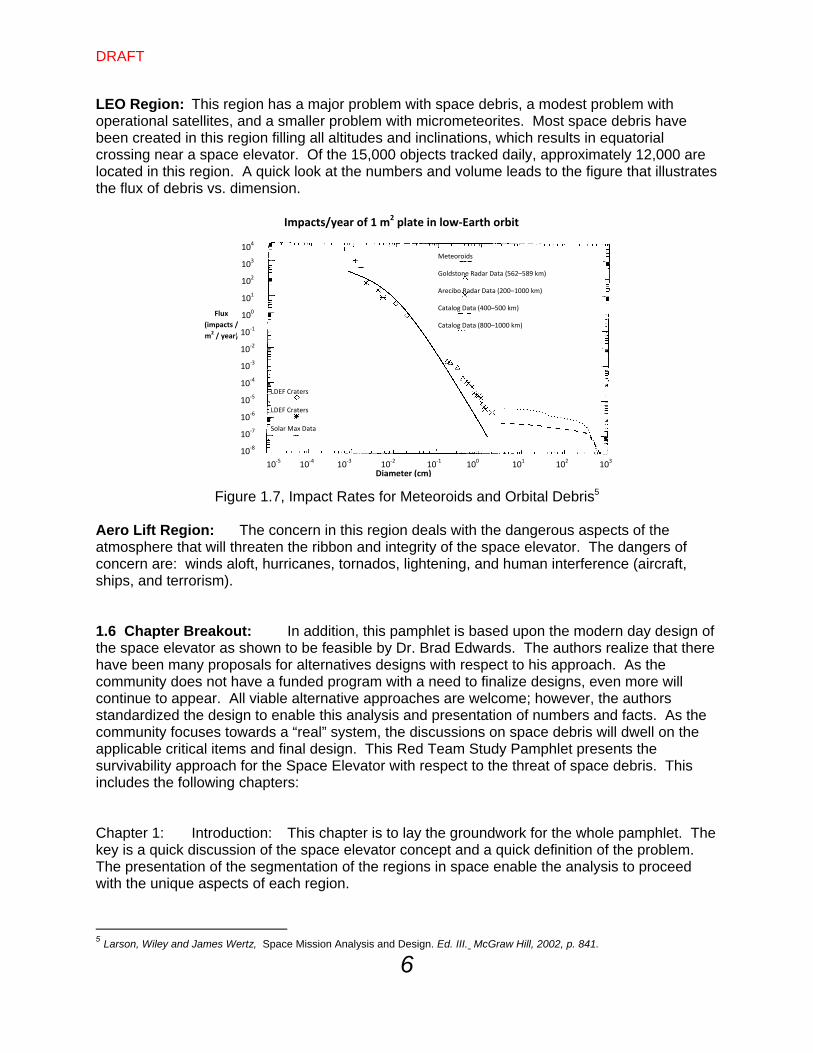
LEO Region: This region has a major problem with space debris, a modest problem with operational satellites, and a smaller problem with micrometeorites. Most space debris have been created in this region filling all altitudes and inclinations, which results in equatorial crossing near a space elevator. Of the 15,000 objects tracked daily, approximately 12,000 are located in this region. A quick look at the numbers and volume leads to the figure that illustrates the flux of debris vs. dimension.
Figure 1.7, Impact Rates for Meteoroids and Orbital Debris5
Aero Lift Region: The concern in this region deals with the dangerous aspects of the atmosphere that will threaten the ribbon and integrity of the space elevator. The dangers of concern are: winds aloft, hurricanes, tornados, lightening, and human interference (aircraft, ships, and terrorism). 1.6 Chapter Breakout: In addition, this pamphlet is based upon the modern day design of the space elevator as shown to be feasible by Dr. Brad Edwards. The authors realize that there have been many proposals for alternatives designs with respect to his approach. As the community does not have a funded program with a need to finalize designs, even more will continue to appear. All viable alternative approaches are welcome; however, the authors standardized the design to enable this analysis and presentation of numbers and facts. As the community focuses towards a “real” system, the discussions on space debris will dwell on the applicable critical items and final design. This Red Team Study Pamphlet presents the survivability approach for the Space Elevator with respect to the threat of space debris. This includes the following chapters: Chapter 1: Introduction: This chapter is to lay the groundwork for the whole pamphlet. The key is a quick discussion of the space elevator concept and a quick definition of the problem. The presentation of the segmentation of the regions in space enable the analysis to proceed with the unique aspects of each region.
5 Larson, Wiley and James Wertz, Space Mission Analysis and Design. Ed. III. McGraw Hill, 2002, p. 841.
Impacts/year of 1 m2 plate in low‐Earth orbit
Diameter (cm)
Flux
(impacts /
m2 / year)
10‐5 10‐4 10‐3 10‐2 10‐1 100 101 102 103
10‐8
10‐5
10‐2
100
102
104
10‐6
10‐7
10‐4
10‐3
10‐1
103
101
LDEF Craters
LDEF Craters
Solar Max Data
Meteoroids
Goldstone Radar Data (562–589 km)
Arecibo Radar Data (200–1000 km)
Catalog Data (400–500 km)
Catalog Data (800–1000 km)
DRAFT
7
Chapter 2: Definition of the Problem: Space Debris, now and into the future: This is a straightforward presentation of the numbers of man-made objects in the appropriate altitude region. A quick discussion of sizes and orbits enables the analysis to proceed and the understanding of the problem be presented. Chapter 3: Probability of Impact: This chapter has the need to present the approach to the calculation and then shows the numbers of importance. Each region has a different set of issues and presents a slightly different set of numbers. The collision probability for each region is then calculated which leads to an understanding of the criticality of space debris against the space elevator. Chapter 4: Mitigation Techniques: The space elevator must be designed and operated to have a “safe” environment. The space elevator must not be severed which would lead to a catastrophe in two areas: Day to day operations and equipment losses, and the realization that the gravity well won the day and we have to start over at GEO. Therefore, the mitigation techniques to ensure that the space elevator does not sever are important to understand and then lead to proposal of implementation techniques for the program. Chapter 5: Conclusions: This chapter will summarize the various regional threats and propose mitigation techniques that will lower the risk to the space elevator. Chapter 6: Recommendations: This pamphlet will present recommendations that should lead to actions within a program office developing the space elevator transportation infrastructure and for the space debris community who need to understand the needs of the space elevator arena. Chapter 7: Projections into the Future: This chapter is to look at the needs of the future and layout a plan to ensure that the space elevator is safe.
DRAFT
8
Chapter 2 – Definition of the Problem: Space Debris, now and the future
2.1 History of Space Debris Problem: There have been four phases to the arena called Space Debris: o Big Sky Theory 1957-1970 No concern because there is so much volume o What is up There? 1970-1989 Scientists/Military wonder what is up there? o Collision Concern 1989-2009 Scientists/mathematicians worry small collision #’s o IRIDIUM-Cosmos 2009- Collision is watershed event – Kessler syndrome 2.1.1 Big Sky Theory (1957-1970) From the beginning, space debris was a constant thorn in the side of space operations. Exploding rocket bodies, batteries exploding inside spacecraft, cameras floating away from astronauts, and old used dead satellites or rocket bodies all created worthless parts in orbit going at orbital velocities. Of course, the volume of space was huge so no one worried. During this time period curious astronomers and interested military officers wanted to know what was up there and who was doing what. As a result, research led to routine systems tracking operational satellites, and by the way, also everything else up there bigger than 10 centimeters. Catalogs were established and predictions for rendezvous (oops collisions) were determined to be very small. 2.1.2 What is up There? (1970-1989) The next phase was one of lets determine what is really up there and who does it belong to. This phase essentially worried about opponents in space versus our own fratricide. This phase had a few people initiating research into residual junk left up there and where would it go. The research concentrated on counting and predicting collisions with low probabilities. Initial efforts were being formed to lower future debris by issuing design guidelines. In addition, the permanent presence of humans with space stations and space shuttles heightened concerns of safety of flight. At the same time, the US and USSR conducted ASAT testing to a limited degree in orbit. 2.1.3 Collision Concern (1989-2009) This phase had many scientists and operators projecting major concerns about the future. However, very little progress was made in active measures to reduce debris in orbit. Much was accomplished in the guidelines for design of spacecraft and rocket bodies culminating on a document expressing the desire for “zero debris creation” as a goal. Most space faring nations incorporated these rules, but did not have any real enforcement approaches. Great strides were being made in calculations of future debris
DRAFT
9
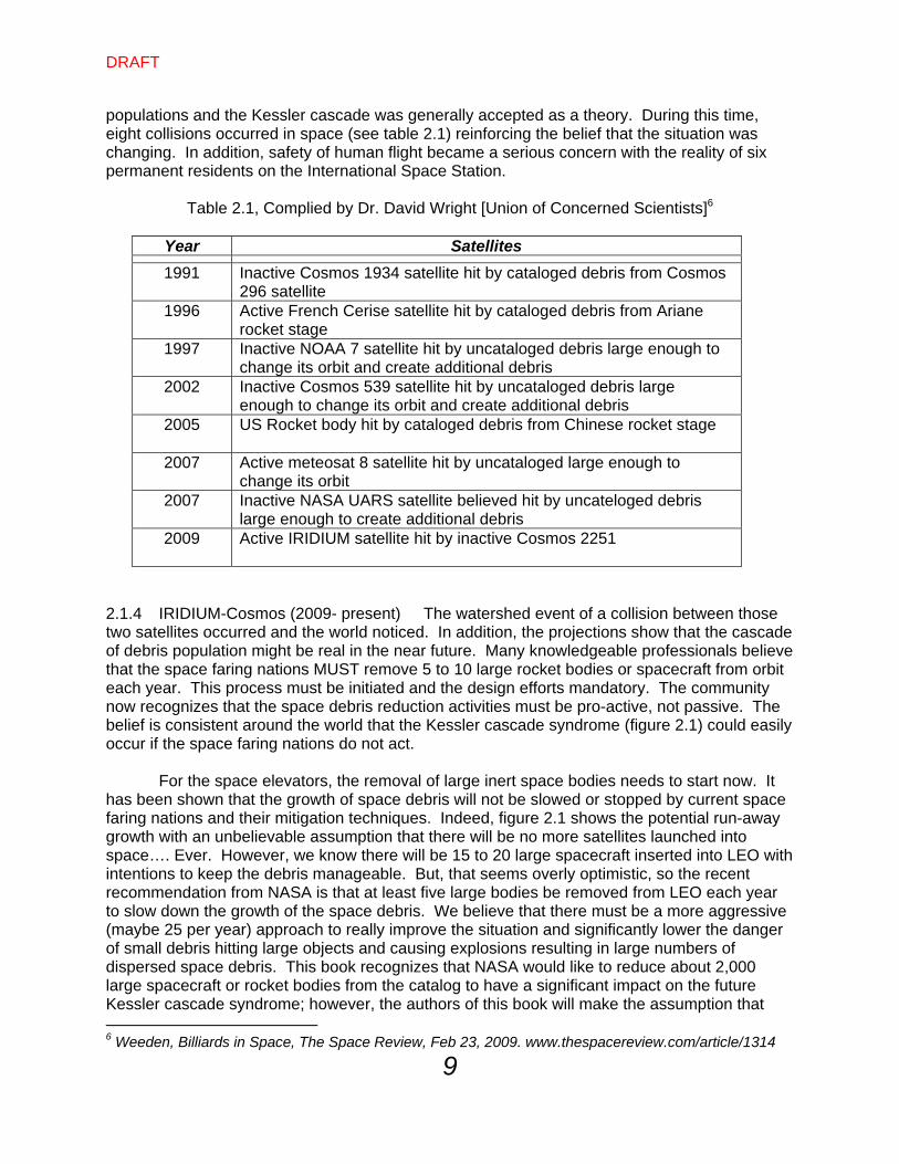
populations and the Kessler cascade was generally accepted as a theory. During this time, eight collisions occurred in space (see table 2.1) reinforcing the belief that the situation was changing. In addition, safety of human flight became a serious concern with the reality of six permanent residents on the International Space Station.
Table 2.1, Complied by Dr. David Wright [Union of Concerned Scientists]6
Year Satellites
1991 Inactive Cosmos 1934 satellite hit by cataloged debris from Cosmos 296 satellite
1996 Active French Cerise satellite hit by cataloged debris from Ariane rocket stage
1997 Inactive NOAA 7 satellite hit by uncataloged debris large enough to change its orbit and create additional debris
2002 Inactive Cosmos 539 satellite hit by uncataloged debris large enough to change its orbit and create additional debris
2005 US Rocket body hit by cataloged debris from Chinese rocket stage
2007 Active meteosat 8 satellite hit by uncataloged large enough to change its orbit
2007 Inactive NASA UARS satellite believed hit by uncateloged debris large enough to create additional debris
2009 Active IRIDIUM satellite hit by inactive Cosmos 2251
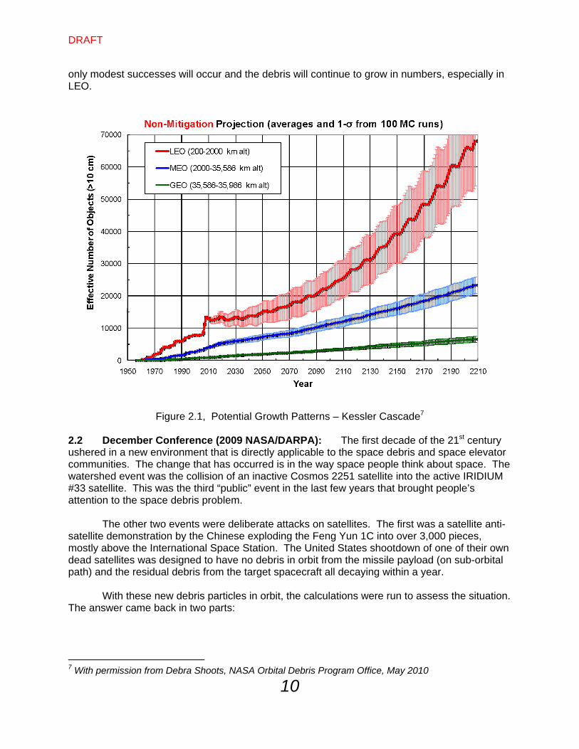
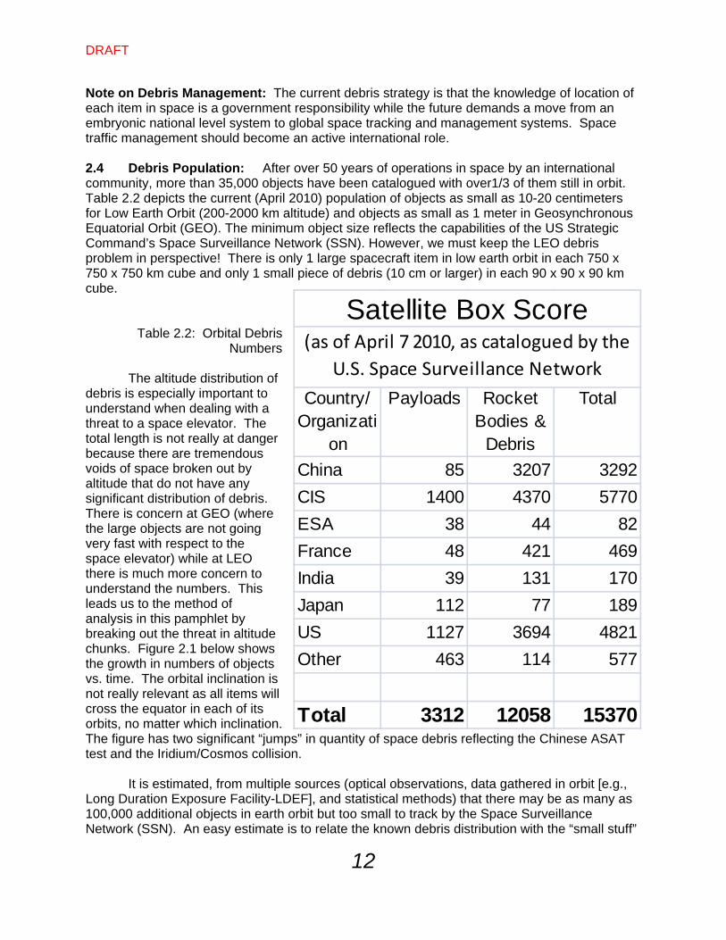
2.1.4 IRIDIUM-Cosmos (2009- present) The watershed event of a collision between those two satellites occurred and the world noticed. In addition, the projections show that the cascade of debris population might be real in the near future. Many knowledgeable professionals believe that the space faring nations MUST remove 5 to 10 large rocket bodies or spacecraft from orbit each year. This process must be initiated and the design efforts mandatory. The community now recognizes that the space debris reduction activities must be pro-active, not passive. The belief is consistent around the world that the Kessler cascade syndrome (figure 2.1) could easily occur if the space faring nations do not act. For the space elevators, the removal of large inert space bodies needs to start now. It has been shown that the growth of space debris will not be slowed or stopped by current space faring nations and their mitigation techniques. Indeed, figure 2.1 shows the potential run-away growth with an unbelievable assumption that there will be no more satellites launched into space…. Ever. However, we know there will be 15 to 20 large spacecraft inserted into LEO with intentions to keep the debris manageable. But, that seems overly optimistic, so the recent recommendation from NASA is that at least five large bodies be removed from LEO each year to slow down the growth of the space debris. We believe that there must be a more aggressive (maybe 25 per year) approach to really improve the situation and significantly lower the danger of small debris hitting large objects and causing explosions resulting in large numbers of dispersed space debris. This book recognizes that NASA would like to reduce about 2,000 large spacecraft or rocket bodies from the catalog to have a significant impact on the future Kessler cascade syndrome; however, the authors of this book will make the assumption that 6 Weeden, Billiards in Space, The Space Review, Feb 23, 2009. www.thespacereview.com/article/1314
DRAFT
10
only modest successes will occur and the debris will continue to grow in numbers, especially in LEO.
Figure 2.1, Potential Growth Patterns – Kessler Cascade7
2.2 December Conference (2009 NASA/DARPA): The first decade of the 21st century ushered in a new environment that is directly applicable to the space debris and space elevator communities. The change that has occurred is in the way space people think about space. The watershed event was the collision of an inactive Cosmos 2251 satellite into the active IRIDIUM #33 satellite. This was the third “public” event in the last few years that brought people’s attention to the space debris problem. The other two events were deliberate attacks on satellites. The first was a satellite anti-satellite demonstration by the Chinese exploding the Feng Yun 1C into over 3,000 pieces, mostly above the International Space Station. The United States shootdown of one of their own dead satellites was designed to have no debris in orbit from the missile payload (on sub-orbital path) and the residual debris from the target spacecraft all decaying within a year. With these new debris particles in orbit, the calculations were run to assess the situation. The answer came back in two parts:
7 With permission from Debra Shoots, NASA Orbital Debris Program Office, May 2010
DRAFT
11
Answer 1: We have crossed over from the position where doing nothing works – the Big Sky theory no longer is applicable as a policy. The space faring nations MUST act in more than a passive manner if LEO is to be of use to us in the future. Answer 2: Calculations showed that the environment is fragile and actions must be initiated. The estimate shows that five large bodies must be removed per year to alter the growing problem we have. Although a big rocket body only counts as a single piece of debris, it has the potential of exploding into thousands when hit by the expected future collisions with small debris. There are over 2,000 large pieces that should be removed to ensure that the cascade effect does not dominate the future environment. These two conclusions were discussed at the 2009 December conference. The papers were very good at describing the problem and explaining the physics of collisions; however, very few papers actually showed “how-to” remove debris from orbit. The papers and discussions showed that there must be an early approach to space debris removal as well as tracking and conjunction analysis. 2.3 Problem Description: What is the probability of puncture from impacts of small items? What is the probability of sever by large orbiting objects? How should the space elevator community plan to mitigate these threats? This pamphlet breaks out the problem within altitude regions to show that the LEO environment is where the greatest hazards exist; where the Medium Altitude (MA) region has a low threat environment [along with Super GEO]; where GEO has slowly drifting space debris, and how the atmospheric region does not worry a lot about debris as space systems do not spend significant operational time below 200 kms. This pamphlet will address three debris threat categories: (a) small [less than 10 cm) which are numerous (10 times the tracked numbers) with random direction, (b) tracked and inert (10 cm and larger) with known numbers and orbital characteristics, and (c) large and controllable (active satellites are about 6% of tracked). During this discussion, the basic assumptions are:
Knowledge of the space elevator incremental segment locations will be estimated from known measurements (GPS, radar, ribbon riders, predictions, retro reflectors).
Knowledge of the debris environment will be known to at least today’s knowledge base [cm’s for exceptional satellites, meters for many large satellites with GPS, 100’s of meters for most and 10’s of kilometers for some].
Only six percent of tracked orbital items are under control with predictable movement, enabling them to maneuver around the space elevator.
Current and future space faring nations will improve their debris mitigation programs over the next ten years.
Some type of active removal will be initiated in the next ten years to ensure the problem to the space elevator does not double in numbers.
DRAFT
12
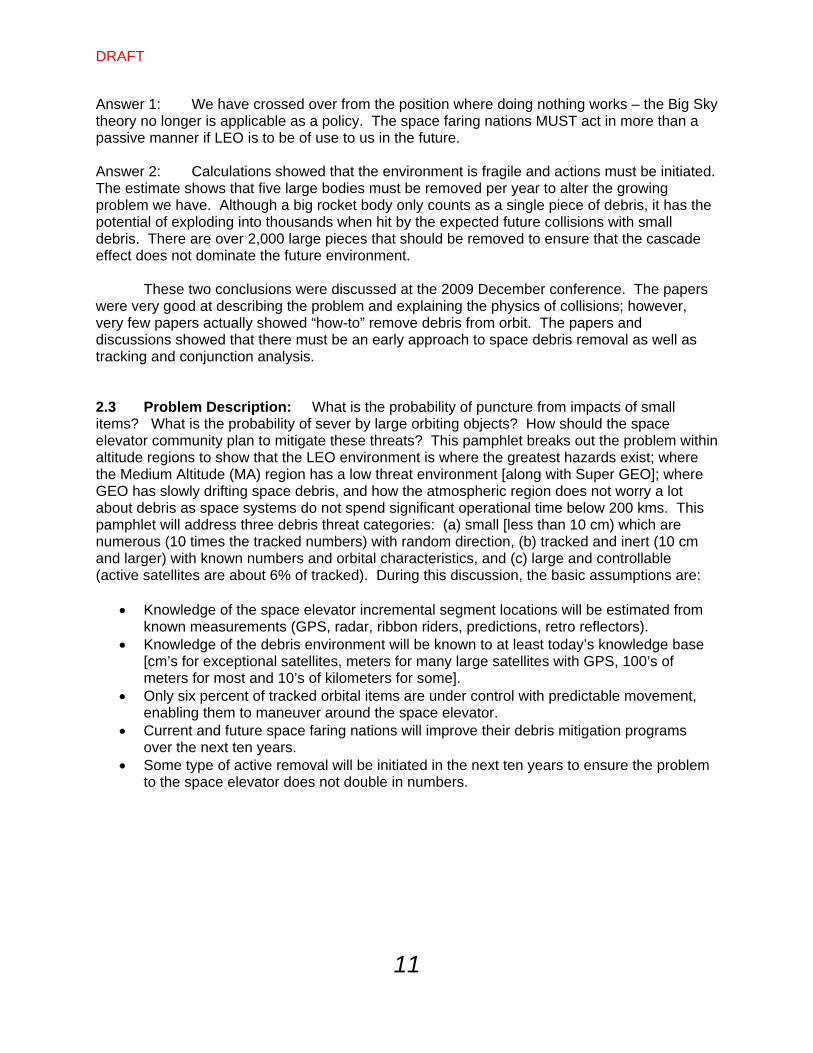
Note on Debris Management: The current debris strategy is that the knowledge of location of each item in space is a government responsibility while the future demands a move from an embryonic national level system to global space tracking and management systems. Space traffic management should become an active international role. 2.4 Debris Population: After over 50 years of operations in space by an international community, more than 35,000 objects have been catalogued with over1/3 of them still in orbit. Table 2.2 depicts the current (April 2010) population of objects as small as 10-20 centimeters for Low Earth Orbit (200-2000 km altitude) and objects as small as 1 meter in Geosynchronous Equatorial Orbit (GEO). The minimum object size reflects the capabilities of the US Strategic Command’s Space Surveillance Network (SSN). However, we must keep the LEO debris problem in perspective! There is only 1 large spacecraft item in low earth orbit in each 750 x 750 x 750 km cube and only 1 small piece of debris (10 cm or larger) in each 90 x 90 x 90 km cube.
Table 2.2: Orbital Debris
Numbers
The altitude distribution of debris is especially important to understand when dealing with a threat to a space elevator. The total length is not really at danger because there are tremendous voids of space broken out by altitude that do not have any significant distribution of debris. There is concern at GEO (where the large objects are not going very fast with respect to the space elevator) while at LEO there is much more concern to understand the numbers. This leads us to the method of analysis in this pamphlet by breaking out the threat in altitude chunks. Figure 2.1 below shows the growth in numbers of objects vs. time. The orbital inclination is not really relevant as all items will cross the equator in each of its orbits, no matter which inclination. The figure has two significant “jumps” in quantity of space debris reflecting the Chinese ASAT test and the Iridium/Cosmos collision.
It is estimated, from multiple sources (optical observations, data gathered in orbit [e.g., Long Duration Exposure Facility-LDEF], and statistical methods) that there may be as many as 100,000 additional objects in earth orbit but too small to track by the Space Surveillance Network (SSN). An easy estimate is to relate the known debris distribution with the “small stuff”
Country/ Organizati
on
Payloads Rocket Bodies &
Debris
Total
China 85 3207 3292
CIS 1400 4370 5770
ESA 38 44 82
France 48 421 469
India 39 131 170
Japan 112 77 189
US 1127 3694 4821
Other 463 114 577
Total 3312 12058 15370
Satellite Box Score(as of April 7 2010, as catalogued by the
U.S. Space Surveillance Network
DRAFT
13
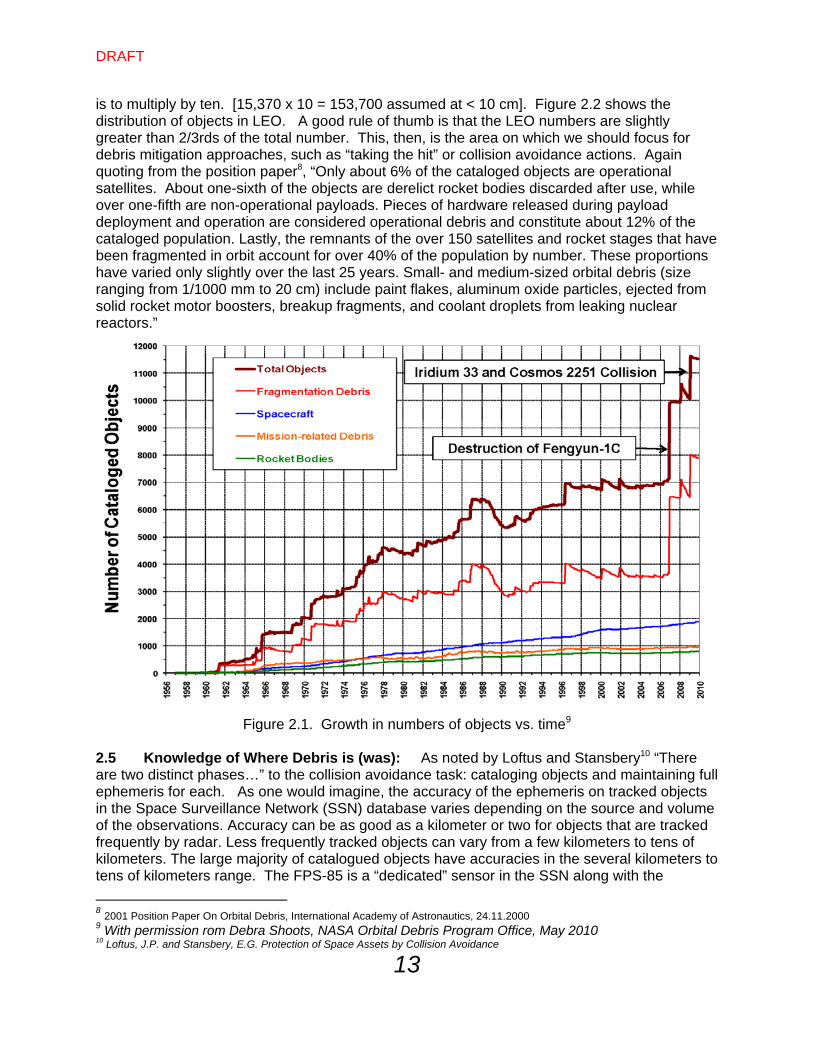
is to multiply by ten. [15,370 x 10 = 153,700 assumed at < 10 cm]. Figure 2.2 shows the distribution of objects in LEO. A good rule of thumb is that the LEO numbers are slightly greater than 2/3rds of the total number. This, then, is the area on which we should focus for debris mitigation approaches, such as “taking the hit” or collision avoidance actions. Again quoting from the position paper8, “Only about 6% of the cataloged objects are operational satellites. About one-sixth of the objects are derelict rocket bodies discarded after use, while over one-fifth are non-operational payloads. Pieces of hardware released during payload deployment and operation are considered operational debris and constitute about 12% of the cataloged population. Lastly, the remnants of the over 150 satellites and rocket stages that have been fragmented in orbit account for over 40% of the population by number. These proportions have varied only slightly over the last 25 years. Small- and medium-sized orbital debris (size ranging from 1/1000 mm to 20 cm) include paint flakes, aluminum oxide particles, ejected from solid rocket motor boosters, breakup fragments, and coolant droplets from leaking nuclear reactors.”
Figure 2.1. Growth in numbers of objects vs. time9
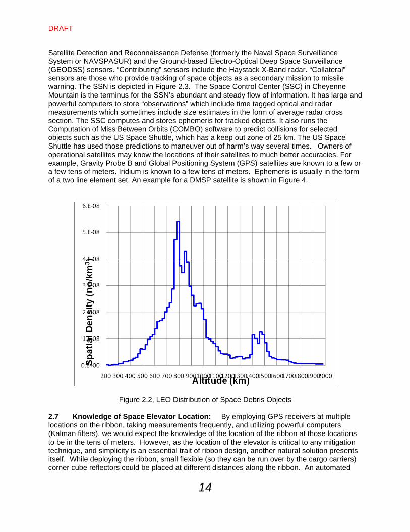
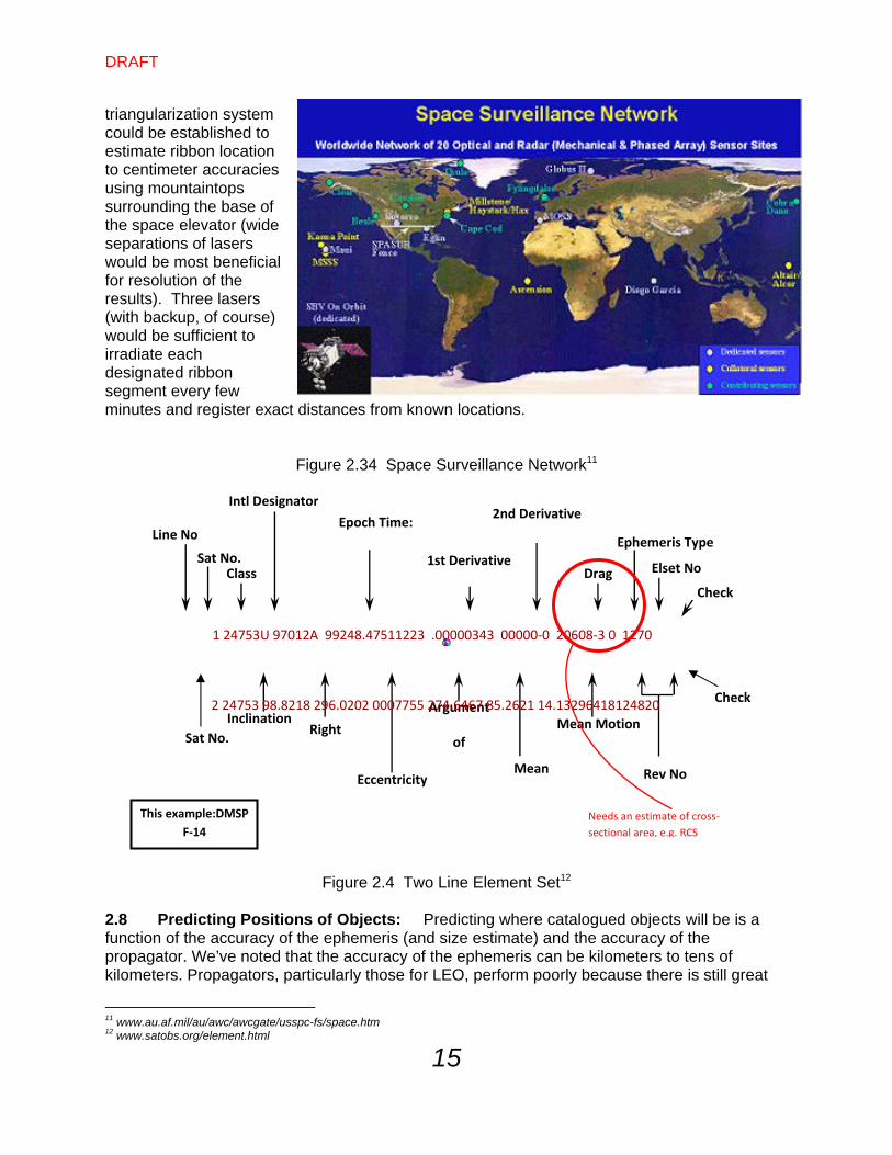
2.5 Knowledge of Where Debris is (was): As noted by Loftus and Stansbery10 “There are two distinct phases…” to the collision avoidance task: cataloging objects and maintaining full ephemeris for each. As one would imagine, the accuracy of the ephemeris on tracked objects in the Space Surveillance Network (SSN) database varies depending on the source and volume of the observations. Accuracy can be as good as a kilometer or two for objects that are tracked frequently by radar. Less frequently tracked objects can vary from a few kilometers to tens of kilometers. The large majority of catalogued objects have accuracies in the several kilometers to tens of kilometers range. The FPS-85 is a “dedicated” sensor in the SSN along with the
8 2001 Position Paper On Orbital Debris, International Academy of Astronautics, 24.11.2000 9 With permission rom Debra Shoots, NASA Orbital Debris Program Office, May 2010 10 Loftus, J.P. and Stansbery, E.G. Protection of Space Assets by Collision Avoidance
DRAFT
14
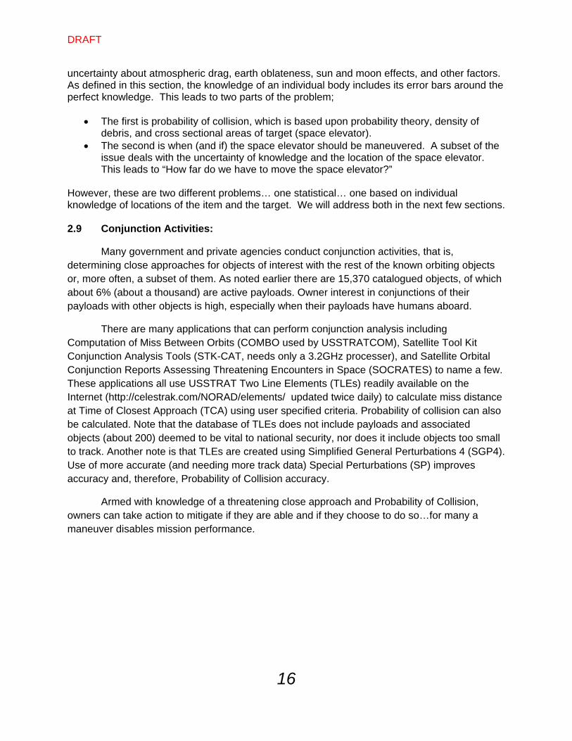
Satellite Detection and Reconnaissance Defense (formerly the Naval Space Surveillance System or NAVSPASUR) and the Ground-based Electro-Optical Deep Space Surveillance (GEODSS) sensors. “Contributing” sensors include the Haystack X-Band radar. “Collateral” sensors are those who provide tracking of space objects as a secondary mission to missile warning. The SSN is depicted in Figure 2.3. The Space Control Center (SSC) in Cheyenne Mountain is the terminus for the SSN’s abundant and steady flow of information. It has large and powerful computers to store “observations” which include time tagged optical and radar measurements which sometimes include size estimates in the form of average radar cross section. The SSC computes and stores ephemeris for tracked objects. It also runs the Computation of Miss Between Orbits (COMBO) software to predict collisions for selected objects such as the US Space Shuttle, which has a keep out zone of 25 km. The US Space Shuttle has used those predictions to maneuver out of harm’s way several times. Owners of operational satellites may know the locations of their satellites to much better accuracies. For example, Gravity Probe B and Global Positioning System (GPS) satellites are known to a few or a few tens of meters. Iridium is known to a few tens of meters. Ephemeris is usually in the form of a two line element set. An example for a DMSP satellite is shown in Figure 4.
Figure 2.2, LEO Distribution of Space Debris Objects 2.7 Knowledge of Space Elevator Location: By employing GPS receivers at multiple locations on the ribbon, taking measurements frequently, and utilizing powerful computers (Kalman filters), we would expect the knowledge of the location of the ribbon at those locations to be in the tens of meters. However, as the location of the elevator is critical to any mitigation technique, and simplicity is an essential trait of ribbon design, another natural solution presents itself. While deploying the ribbon, small flexible (so they can be run over by the cargo carriers) corner cube reflectors could be placed at different distances along the ribbon. An automated
DRAFT
15
triangularization system could be established to estimate ribbon location to centimeter accuracies using mountaintops surrounding the base of the space elevator (wide separations of lasers would be most beneficial for resolution of the results). Three lasers (with backup, of course) would be sufficient to irradiate each designated ribbon segment every few minutes and register exact distances from known locations.
Figure 2.34 Space Surveillance Network11
Figure 2.4 Two Line Element Set12
2.8 Predicting Positions of Objects: Predicting where catalogued objects will be is a function of the accuracy of the ephemeris (and size estimate) and the accuracy of the propagator. We’ve noted that the accuracy of the ephemeris can be kilometers to tens of kilometers. Propagators, particularly those for LEO, perform poorly because there is still great
11 www.au.af.mil/au/awc/awcgate/usspc-fs/space.htm 12 www.satobs.org/element.html
Line No
Sat No. Class
Epoch Time:2nd Derivative
Drag Elset No
Check
Inclination Right
Eccentricity
Argument
of
Mean
Mean Motion
Rev No
This example:DMSP
F‐14
Intl Designator
Ephemeris Type
Sat No.
Check
1st Derivative
1 24753U 97012A 99248.47511223 .00000343 00000‐0 20608‐3 0 1270
2 24753 98.8218 296.0202 0007755 274.6467 85.2621 14.13296418124820
Needs an estimate of cross‐
sectional area, e.g. RCS
DRAFT
16
uncertainty about atmospheric drag, earth oblateness, sun and moon effects, and other factors. As defined in this section, the knowledge of an individual body includes its error bars around the perfect knowledge. This leads to two parts of the problem;
The first is probability of collision, which is based upon probability theory, density of debris, and cross sectional areas of target (space elevator).
The second is when (and if) the space elevator should be maneuvered. A subset of the issue deals with the uncertainty of knowledge and the location of the space elevator. This leads to “How far do we have to move the space elevator?”
However, these are two different problems… one statistical… one based on individual knowledge of locations of the item and the target. We will address both in the next few sections. 2.9 Conjunction Activities:
Many government and private agencies conduct conjunction activities, that is, determining close approaches for objects of interest with the rest of the known orbiting objects or, more often, a subset of them. As noted earlier there are 15,370 catalogued objects, of which about 6% (about a thousand) are active payloads. Owner interest in conjunctions of their payloads with other objects is high, especially when their payloads have humans aboard.
There are many applications that can perform conjunction analysis including Computation of Miss Between Orbits (COMBO used by USSTRATCOM), Satellite Tool Kit Conjunction Analysis Tools (STK-CAT, needs only a 3.2GHz processer), and Satellite Orbital Conjunction Reports Assessing Threatening Encounters in Space (SOCRATES) to name a few. These applications all use USSTRAT Two Line Elements (TLEs) readily available on the Internet (http://celestrak.com/NORAD/elements/ updated twice daily) to calculate miss distance at Time of Closest Approach (TCA) using user specified criteria. Probability of collision can also be calculated. Note that the database of TLEs does not include payloads and associated objects (about 200) deemed to be vital to national security, nor does it include objects too small to track. Another note is that TLEs are created using Simplified General Perturbations 4 (SGP4). Use of more accurate (and needing more track data) Special Perturbations (SP) improves accuracy and, therefore, Probability of Collision accuracy.
Armed with knowledge of a threatening close approach and Probability of Collision, owners can take action to mitigate if they are able and if they choose to do so…for many a maneuver disables mission performance.
DRAFT
17
Chapter 3 – Probability of Impact 3.1 Risk of Debris to Space Elevator: Quoting from the 2001 IAA Position Paper On Orbital Debris13, “The probability (PC) that two items will collide in orbit is a function of the spatial density (SPD) of orbiting objects in a region, the average relative velocity (VR) between the objects in that region, the collision cross section (XC) of the scenario being considered, and the time (T) the object at risk is in the given region.
PC = 1 – e(-VR x SPD x XC x T)
The relationship is derived from the kinetic energy theory of gases by assuming that the relative motion of objects in the region being considered is random. This methodology was introduced in 1983, by Penny/Jones in their Masters thesis “A Model for Evaluation of Satellite Population Management Alternatives.14” Note, that the PC equation may be approximated by the product of the four terms as long as the value is very small (less than 1/100). As the cataloged population, lifetime, and satellite size increase, the PC will also increase. We do not use the product method since we anticipate PC being larger than 1/100. An example of area is as if we just consider the LEO area [200 to 2,000 km altitude] of the ribbon, the cross sectional area is 1,800,000 meters times 1 meter or 1,800,000 square meters, or 1.8 square kilometers. The relative velocity is the average velocity for objects in LEO since the ribbon is essentially stationary and direction of debris is random. The potential colliders would number in the tens of thousands in the LEO region.”
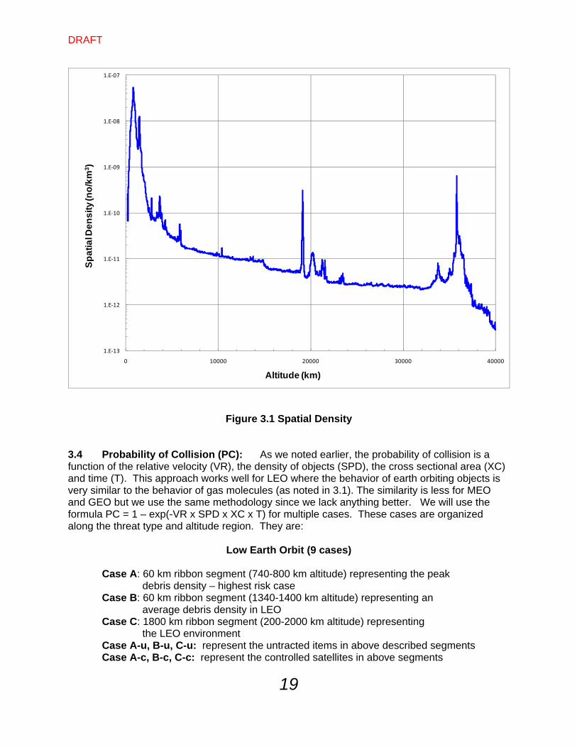
3.2 Relational Velocities: To calculate the probabilities of collision, relational velocities must be estimated for each region. The following two charts look at the definition of relational velocities in different manners: by altitude breakout, and by specific altitude breakouts. 3.3 Altitude Densities: Figure 3.1 shows the breakout of numbers of tracked debris vs. altitude. This chart is used to calculate densities of space debris into the altitude bins used to calculate the probability of collision. The data was provided in 20 km “shells” of altitude densities by the NASA Orbital Debris Program Office in Houston.
13 2001 Position Paper On Orbital Debris, International Academy of Astronautics, 24.11.2000 14 Penny, Robert and Charles Jones, “A Model for Evaluation of Satellite Population Management Alternatives,” AFIT Masters Thesis, 1983.
DRAFT
18
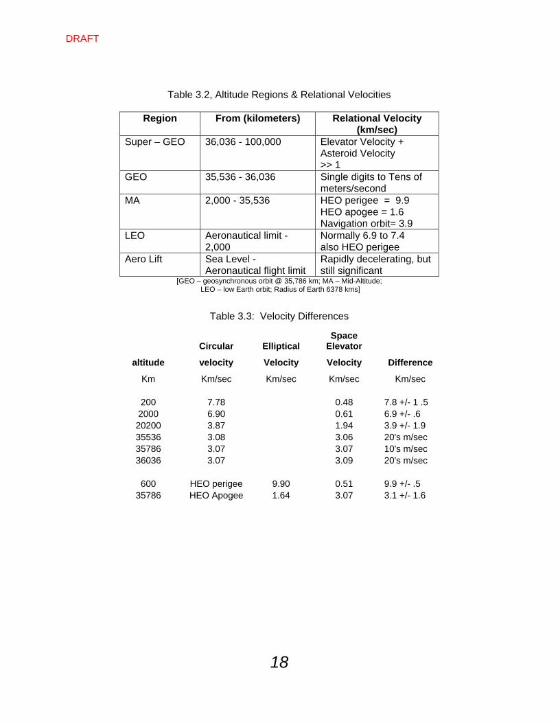
Table 3.2, Altitude Regions & Relational Velocities
Region From (kilometers) Relational Velocity (km/sec)
Super – GEO 36,036 - 100,000 Elevator Velocity + Asteroid Velocity >> 1
GEO 35,536 - 36,036 Single digits to Tens of meters/second
MA 2,000 - 35,536 HEO perigee = 9.9 HEO apogee = 1.6 Navigation orbit= 3.9
LEO Aeronautical limit - 2,000
Normally 6.9 to 7.4 also HEO perigee
Aero Lift Sea Level - Aeronautical flight limit
Rapidly decelerating, but still significant
[GEO – geosynchronous orbit @ 35,786 km; MA – Mid-Altitude; LEO – low Earth orbit; Radius of Earth 6378 kms]
Table 3.3: Velocity Differences
Circular Elliptical Space
Elevator
altitude velocity Velocity Velocity Difference
Km Km/sec Km/sec Km/sec Km/sec
200 7.78 0.48 7.8 +/- 1 .5 2000 6.90 0.61 6.9 +/- .6 20200 3.87 1.94 3.9 +/- 1.9 35536 3.08 3.06 20's m/sec 35786 3.07 3.07 10's m/sec 36036 3.07 3.09 20's m/sec
600 HEO perigee 9.90 0.51 9.9 +/- .5 35786 HEO Apogee 1.64 3.07 3.1 +/- 1.6
DRAFT
19
1.E‐13
1.E‐12
1.E‐11
1.E‐10
1.E‐09
1.E‐08
1.E‐07
0 10000 20000 30000 40000
Sp
ati
al D
en
sit
y (n
o/k
m3)
Altitude (km)
Figure 3.1 Spatial Density 3.4 Probability of Collision (PC): As we noted earlier, the probability of collision is a function of the relative velocity (VR), the density of objects (SPD), the cross sectional area (XC) and time (T). This approach works well for LEO where the behavior of earth orbiting objects is very similar to the behavior of gas molecules (as noted in 3.1). The similarity is less for MEO and GEO but we use the same methodology since we lack anything better. We will use the formula PC = 1 – exp(-VR x SPD x XC x T) for multiple cases. These cases are organized along the threat type and altitude region. They are:
Low Earth Orbit (9 cases)
Case A: 60 km ribbon segment (740-800 km altitude) representing the peak debris density – highest risk case Case B: 60 km ribbon segment (1340-1400 km altitude) representing an average debris density in LEO Case C: 1800 km ribbon segment (200-2000 km altitude) representing the LEO environment Case A-u, B-u, C-u: represent the untracted items in above described segments Case A-c, B-c, C-c: represent the controlled satellites in above segments
DRAFT
20
Medium Earth Orbit
Case D: 200 km ribbon segment (around 20,200 km altitude) representing the Navigation orbit environment [only tracked items are calculated]
GEO Orbit
Case E: 200 km ribbon segment (35,680 - 36,880 km altitude) representing the GEO environment [only tracked items are calculated]
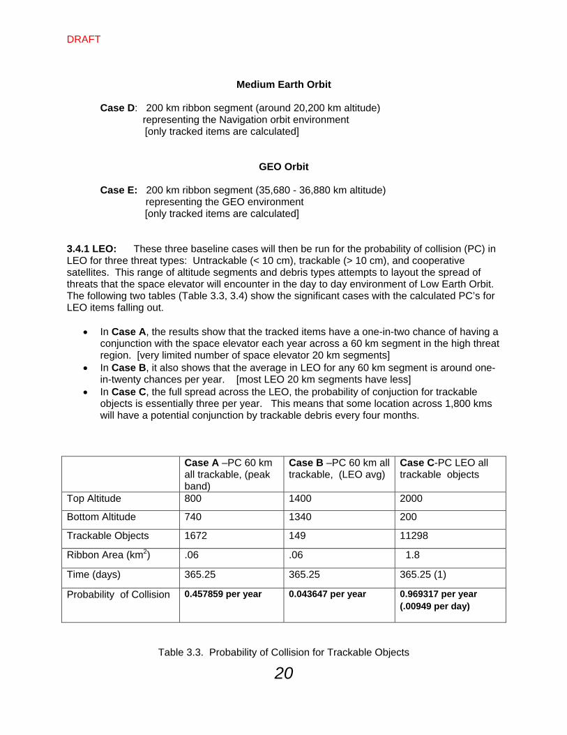
3.4.1 LEO: These three baseline cases will then be run for the probability of collision (PC) in LEO for three threat types: Untrackable (< 10 cm), trackable (> 10 cm), and cooperative satellites. This range of altitude segments and debris types attempts to layout the spread of threats that the space elevator will encounter in the day to day environment of Low Earth Orbit. The following two tables (Table 3.3, 3.4) show the significant cases with the calculated PC’s for LEO items falling out.
In Case A, the results show that the tracked items have a one-in-two chance of having a conjunction with the space elevator each year across a 60 km segment in the high threat region. [very limited number of space elevator 20 km segments]
In Case B, it also shows that the average in LEO for any 60 km segment is around one-in-twenty chances per year. [most LEO 20 km segments have less]
In Case C, the full spread across the LEO, the probability of conjuction for trackable objects is essentially three per year. This means that some location across 1,800 kms will have a potential conjunction by trackable debris every four months.
Case A –PC 60 km
all trackable, (peak band)
Case B –PC 60 km all trackable, (LEO avg)
Case C-PC LEO all trackable objects
Top Altitude 800 1400 2000
Bottom Altitude 740 1340 200
Trackable Objects 1672 149 11298
Ribbon Area (km2) .06 .06 1.8
Time (days) 365.25 365.25 365.25 (1)
Probability of Collision 0.457859 per year 0.043647 per year 0.969317 per year (.00949 per day)
Table 3.3. Probability of Collision for Trackable Objects
DRAFT
21
One must remember that, when dealing with tracked objects, we know where the debris
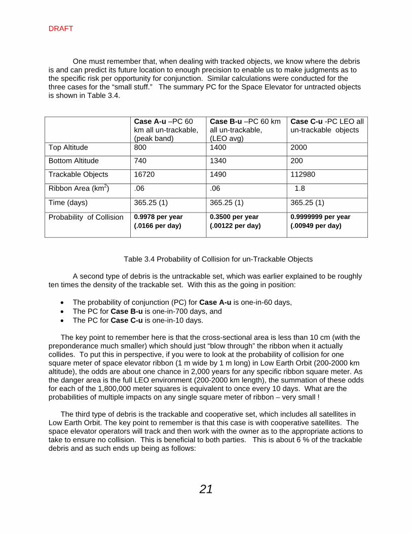
is and can predict its future location to enough precision to enable us to make judgments as to the specific risk per opportunity for conjunction. Similar calculations were conducted for the three cases for the “small stuff.” The summary PC for the Space Elevator for untracted objects is shown in Table 3.4.
Case A-u –PC 60 km all un-trackable, (peak band)
Case B-u –PC 60 km all un-trackable, (LEO avg)
Case C-u -PC LEO all un-trackable objects
Top Altitude 800 1400 2000
Bottom Altitude 740 1340 200
Trackable Objects 16720 1490 112980
Ribbon Area (km2) .06 .06 1.8
Time (days) 365.25 (1) 365.25 (1) 365.25 (1)
Probability of Collision 0.9978 per year (.0166 per day)
0.3500 per year (.00122 per day)
0.9999999 per year (.00949 per day)
Table 3.4 Probability of Collision for un-Trackable Objects A second type of debris is the untrackable set, which was earlier explained to be roughly
ten times the density of the trackable set. With this as the going in position:
The probability of conjunction (PC) for Case A-u is one-in-60 days, The PC for Case B-u is one-in-700 days, and The PC for Case C-u is one-in-10 days.
The key point to remember here is that the cross-sectional area is less than 10 cm (with the
preponderance much smaller) which should just “blow through” the ribbon when it actually collides. To put this in perspective, if you were to look at the probability of collision for one square meter of space elevator ribbon (1 m wide by 1 m long) in Low Earth Orbit (200-2000 km altitude), the odds are about one chance in 2,000 years for any specific ribbon square meter. As the danger area is the full LEO environment (200-2000 km length), the summation of these odds for each of the 1,800,000 meter squares is equivalent to once every 10 days. What are the probabilities of multiple impacts on any single square meter of ribbon – very small !
The third type of debris is the trackable and cooperative set, which includes all satellites in Low Earth Orbit. The key point to remember is that this case is with cooperative satellites. The space elevator operators will track and then work with the owner as to the appropriate actions to take to ensure no collision. This is beneficial to both parties. This is about 6 % of the trackable debris and as such ends up being as follows:
DRAFT
22
Case A-c yields a collision every 30 years Case B-c yields a collision every 400 years Case C-c yields a collision every 5 years
Table 3.5 Probability of Collision LEO Summary 3.3.2 Medium Orbit:
Case D: 200 km ribbon segment (20,200 km altitude) representing the Navigation orbit environment
3.3.3 GEO:
Case E: 200 km ribbon segment (35,680 - 36,880 km altitude) representing the GEO environment
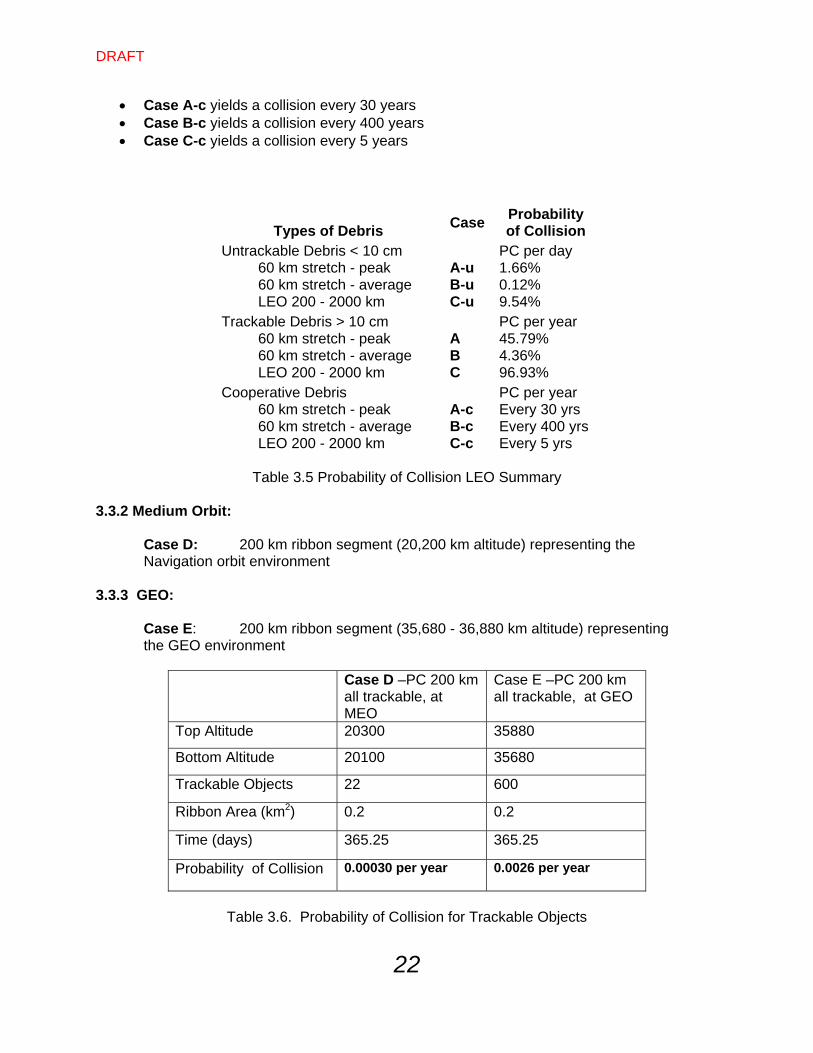
Case D –PC 200 km
all trackable, at MEO
Case E –PC 200 km all trackable, at GEO
Top Altitude 20300 35880
Bottom Altitude 20100 35680
Trackable Objects 22 600
Ribbon Area (km2) 0.2 0.2
Time (days) 365.25 365.25
Probability of Collision 0.00030 per year 0.0026 per year
Table 3.6. Probability of Collision for Trackable Objects
Types of Debris
Case
Probability of Collision
Untrackable Debris < 10 cm PC per day 60 km stretch - peak A-u 1.66% 60 km stretch - average B-u 0.12% LEO 200 - 2000 km C-u 9.54% Trackable Debris > 10 cm PC per year 60 km stretch - peak A 45.79% 60 km stretch - average B 4.36% LEO 200 - 2000 km C 96.93% Cooperative Debris PC per year 60 km stretch - peak A-c Every 30 yrs 60 km stretch - average B-c Every 400 yrs LEO 200 - 2000 km C-c Every 5 yrs
DRAFT
23
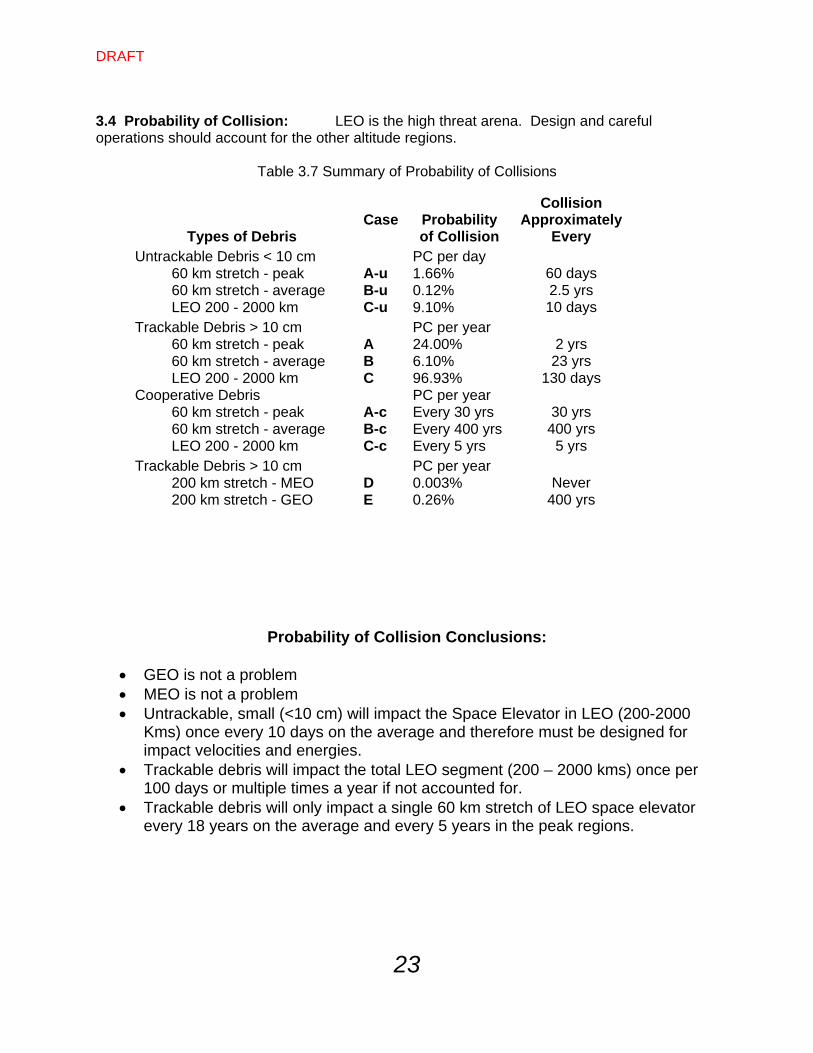
3.4 Probability of Collision: LEO is the high threat arena. Design and careful operations should account for the other altitude regions.
Table 3.7 Summary of Probability of Collisions
Probability of Collision Conclusions:
GEO is not a problem MEO is not a problem Untrackable, small (<10 cm) will impact the Space Elevator in LEO (200-2000
Kms) once every 10 days on the average and therefore must be designed for impact velocities and energies.
Trackable debris will impact the total LEO segment (200 – 2000 kms) once per 100 days or multiple times a year if not accounted for.
Trackable debris will only impact a single 60 km stretch of LEO space elevator every 18 years on the average and every 5 years in the peak regions.
Types of Debris
Case Probability
of Collision
Collision Approximately
Every
Untrackable Debris < 10 cm PC per day 60 km stretch - peak A-u 1.66% 60 days 60 km stretch - average B-u 0.12% 2.5 yrs LEO 200 - 2000 km C-u 9.10% 10 days Trackable Debris > 10 cm PC per year 60 km stretch - peak A 24.00% 2 yrs 60 km stretch - average B 6.10% 23 yrs LEO 200 - 2000 km C 96.93% 130 days Cooperative Debris PC per year 60 km stretch - peak A-c Every 30 yrs 30 yrs 60 km stretch - average B-c Every 400 yrs 400 yrs LEO 200 - 2000 km C-c Every 5 yrs 5 yrs Trackable Debris > 10 cm PC per year 200 km stretch - MEO D 0.003% Never 200 km stretch - GEO E 0.26% 400 yrs
DRAFT
24
Chapter 4 – Mitigation Techniques 4.1 User Needs – System Objectives: The space elevator will be designed with many factors included in the trade space. Some anticipated desires of the customers and users for survivability of the architecture vs. space debris are:
Zero Sever Infrastructure (the space elevator, once established will never lead to a vacuum of transportation infrastructure “beating the gravity well.”
Robust Ribbon (the ribbon must be able to take punishment and keep on operating) Robust Situational Awareness (knowledge of the environment must be as complete as
possible – better tracking of space objects and location of space elevator segments) Multiple ribbons ensuring the continuation of “winning the gravity well wars.”
These objectives lead to a basic expectation, or goal, of a space elevator infrastructure:
“Safe Operations”
4.2 User Requirements: The following user requirements cover many issues within the Space Elevator Safe Operations Concept. A quick summary (table 5) is shown below with many of the items directly related to the problem of space debris. 4.3 Potential Solutions to Debris Threats: Within the above requirements leading to safe operations is the problem of understanding the space debris and its impact on space elevators. However, the recognition of the characteristics of space debris and the understanding of the dynamics of the space elevator lead to potential solutions mitigating the threat. The following approaches reach across the diverse characteristics and offer engineering solutions toward safe operations. The following are described in general terms and may be applied along the total ribbon length or just where a certain threat is most significant.
DRAFT
25
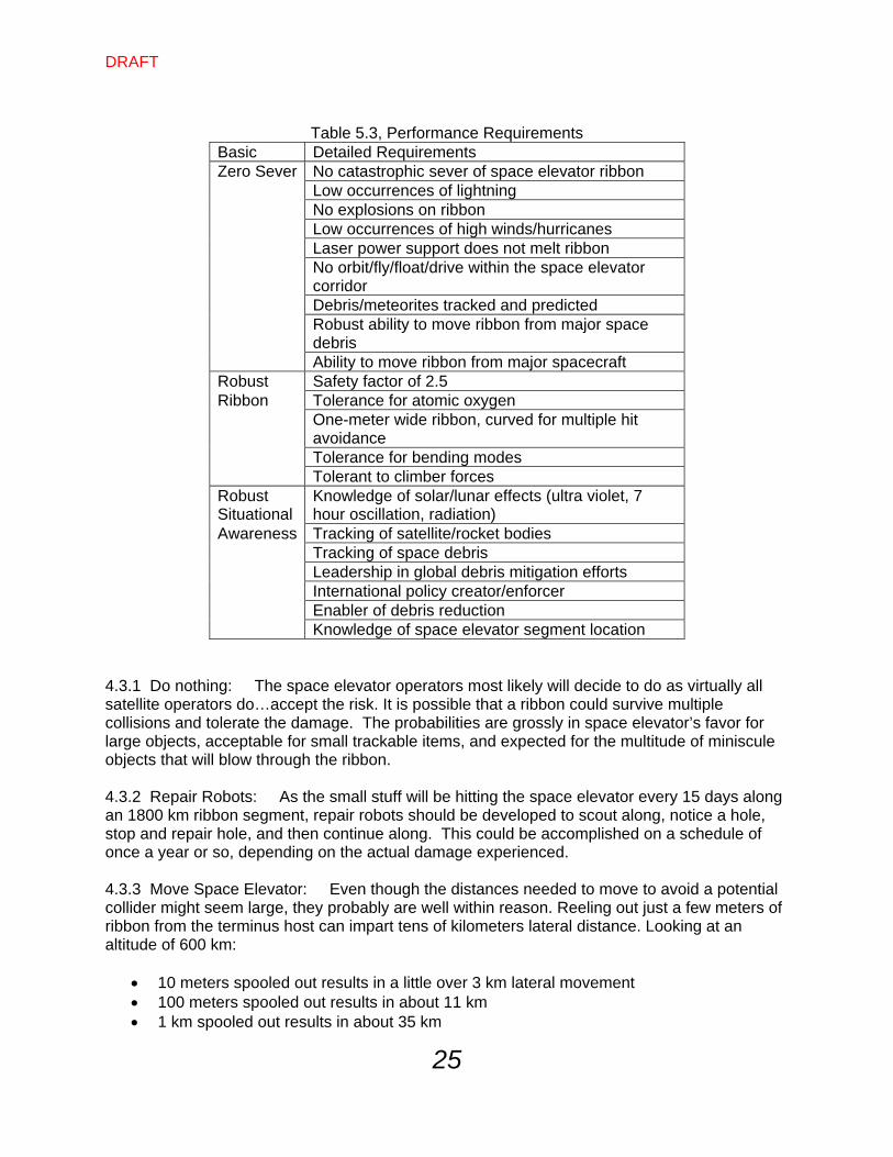
Table 5.3, Performance Requirements
Basic Detailed Requirements Zero Sever No catastrophic sever of space elevator ribbon Low occurrences of lightning No explosions on ribbon Low occurrences of high winds/hurricanes Laser power support does not melt ribbon No orbit/fly/float/drive within the space elevator
corridor Debris/meteorites tracked and predicted Robust ability to move ribbon from major space
debris Ability to move ribbon from major spacecraft Robust Safety factor of 2.5 Ribbon Tolerance for atomic oxygen One-meter wide ribbon, curved for multiple hit
avoidance Tolerance for bending modes Tolerant to climber forces Robust Situational
Knowledge of solar/lunar effects (ultra violet, 7 hour oscillation, radiation)
Awareness Tracking of satellite/rocket bodies Tracking of space debris Leadership in global debris mitigation efforts International policy creator/enforcer Enabler of debris reduction Knowledge of space elevator segment location
4.3.1 Do nothing: The space elevator operators most likely will decide to do as virtually all satellite operators do…accept the risk. It is possible that a ribbon could survive multiple collisions and tolerate the damage. The probabilities are grossly in space elevator’s favor for large objects, acceptable for small trackable items, and expected for the multitude of miniscule objects that will blow through the ribbon. 4.3.2 Repair Robots: As the small stuff will be hitting the space elevator every 15 days along an 1800 km ribbon segment, repair robots should be developed to scout along, notice a hole, stop and repair hole, and then continue along. This could be accomplished on a schedule of once a year or so, depending on the actual damage experienced. 4.3.3 Move Space Elevator: Even though the distances needed to move to avoid a potential collider might seem large, they probably are well within reason. Reeling out just a few meters of ribbon from the terminus host can impart tens of kilometers lateral distance. Looking at an altitude of 600 km:
10 meters spooled out results in a little over 3 km lateral movement 100 meters spooled out results in about 11 km 1 km spooled out results in about 35 km
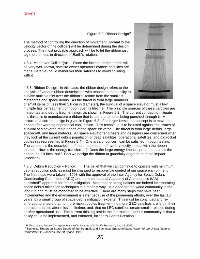
DRAFT
26
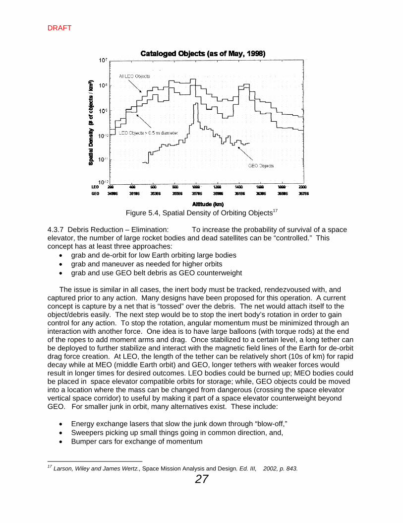
Figure 5.3, Ribbon Design15 The method of controlling the direction of movement (normal to the velocity vector of the collider) will be determined during the design process. The most probable approach will be to let the ribbon just lag more or less in direction of Earth’s rotation. 4.3.4 Maneuver Collider(s): Since the location of the ribbon will be very well known, satellite owner operators (whose satellites are maneuverable) could maneuver their satellites to avoid colliding with it. 4.3.5 Ribbon Design: In this case, the ribbon design refers to the analysis of various ribbon descriptions with respect to their ability to survive multiple hits over the ribbon’s lifetime from the smallest meteorites and space debris. As the threat is from large numbers of small items of (less than 1.0 cm in diameter), the survival of a space elevator must allow multiple hits per segment of ribbon over its lifetime. The principle sources of these particles are meteorites and debris fragmentation, as shown in Figure 5.2. The current concept to mitigate this threat is to manufacture a ribbon that is tolerant to holes being punched through it. A picture of a current design is given in Figure 5.3. For larger items, the concept is to move the ribbon after warning of potential conjunction. This technique is to be used against the issues of survival of a severed main ribbon of the space elevator. The threat is from large debris, large spacecraft, and large meteors. All space elevator engineers and designers are concerned when they look at the current debris population of dead satellites, operational satellites, and old rocket bodies (as represented in Figure 5.4). One area of concern can be satisfied through testing. The concern is the description of the phenomenon of hyper-velocity impact with the ribbon strands. How is the energy transferred? Does the large energy impact spread out across the ribbon, or is it localized? Can we design the ribbon to gracefully degrade at those impact velocities? 4.3.6 Debris Reduction – Policy: The belief that we can continue to operate with minimum debris reduction policies must be changed to responsible control of our space environment. The first steps were taken in 1998 with the approval of the Inter-Agency for Space Debris Coordinating Committee (IADC) and the International Academy of Astronautics (IAA) published16 approach for debris mitigation. Major space faring nations are indeed incorporating space debris mitigation techniques in a modest way. It is good for the world community in the long run and must be mandated to be effective. There are many steps that have been implemented and the environment is safer because of the pioneering efforts, over the last 10 years, by a small group of space debris mitigation experts. This must be continued and re-enforced to ensure that no more rocket bodies fragment; no more GEO satellites are left in their operational orbits after mission lifetime; and, that no LEO satellites create smaller pieces during or after operational use. The current thinking inside the international debris community is that a policy could be implemented, and enforced, for “Zero Debris Creation.”
15 Pullum, Laura, Private Correspondence within Institute of Scientific Research, Aug 24, 2005. 16 Technical Report on Space Debris of the Scientific and Technical Subcommittee, Report of the United Nations Committee On Peaceful Use Of Space. 1999.
DRAFT
27
Figure 5.4, Spatial Density of Orbiting Objects17
4.3.7 Debris Reduction – Elimination: To increase the probability of survival of a space elevator, the number of large rocket bodies and dead satellites can be “controlled.” This concept has at least three approaches:
grab and de-orbit for low Earth orbiting large bodies grab and maneuver as needed for higher orbits grab and use GEO belt debris as GEO counterweight
The issue is similar in all cases, the inert body must be tracked, rendezvoused with, and
captured prior to any action. Many designs have been proposed for this operation. A current concept is capture by a net that is “tossed” over the debris. The net would attach itself to the object/debris easily. The next step would be to stop the inert body’s rotation in order to gain control for any action. To stop the rotation, angular momentum must be minimized through an interaction with another force. One idea is to have large balloons (with torque rods) at the end of the ropes to add moment arms and drag. Once stabilized to a certain level, a long tether can be deployed to further stabilize and interact with the magnetic field lines of the Earth for de-orbit drag force creation. At LEO, the length of the tether can be relatively short (10s of km) for rapid decay while at MEO (middle Earth orbit) and GEO, longer tethers with weaker forces would result in longer times for desired outcomes. LEO bodies could be burned up; MEO bodies could be placed in space elevator compatible orbits for storage; while, GEO objects could be moved into a location where the mass can be changed from dangerous (crossing the space elevator vertical space corridor) to useful by making it part of a space elevator counterweight beyond GEO. For smaller junk in orbit, many alternatives exist. These include:
Energy exchange lasers that slow the junk down through “blow-off,” Sweepers picking up small things going in common direction, and, Bumper cars for exchange of momentum
17 Larson, Wiley and James Wertz., Space Mission Analysis and Design. Ed. III, 2002, p. 843.
DRAFT
28
To accomplish this task of elimination of junk in space, space nations could fund the clean-up similar to an environmental spill. If a space elevator is going to cost in the range of $10-40 billion, maybe a billion dollars could be put forth to clear-up space. How many entrepreneurs will surface when you explain that they can make $100 per kilogram for inert spacecraft or rocket body de-orbit, or movement to a stabilized orbit. This would be roughly 11,000 pieces for $1 billion. Two recent papers18&19 discussed the concept of attaching to space objects and moving them.
4.3.8 Satellite Control – Knowledge: The current technology of radar and optical trackers (combined with older computers and software) leads to a situation where lack of knowledge of space debris is worrisome for space elevator designers. To apply techniques that could greatly enhance the safety of a space elevator, precise knowledge of the orbiting particles must be routine and continuous. New emphasis must be applied to better tracking (maybe even from platforms on a space elevator), computing, understanding, and prediction. 4.3.9 Satellite Control – Maneuver: As a space elevator is developed, new spacecraft should have non-threatening orbits, or, if necessary, maneuver around the vertical space corridor holding a space elevator. This would require a more robust propulsion system with the controls necessary to avoid the vertical space corridor. 4.3.10 Rules of the Road, Nodal Control: In addition to knowledge of where active spacecraft are, there should be a policy at the international level that mandates repetitive orbits well clear of a space elevator vertical space corridor. These are also called harmonic orbits because the periods of the orbits are divisible by an even number and have repeating equatorial node crossing. Most satellites have orbits near 90 minutes or 120 minutes or multiples of those numbers. With proper planning and execution, orbits can be arranged to have precise segments of the sidereal day. This would mean that these orbits would be able to repeat equatorial crossing and avoid the vertical corridor of a space elevator. This is the current policy at GEO (International Telecommunications Union (ITU) allocated slots) and could very easily be mandated for other orbits. One key is that most missions in space have multiple requirements that lead to orbital selection. By making equatorial crossings repetitive, to avoid a space elevator, an additional requirement in the design trade space, most missions would not be significantly effected. 4.3.11 Ribbon Motion: A space elevator can be moved from its natural position to avoid collisions. The risk of collision is real and, therefore, requires this capability as not all maneuvering can be mandated for debris. This motion could be modeled during the design phase to ensure that the dynamic stresses were included in the material selection and architecture. 4.4 Systems Approach for Survival: A systems approach for the evaluation of the survival of a space elevator enables the designers and backers to confidentially proceed with the research and development phase of the program. Even though the threat for space elevators is complex and multi-dimensional, designs are flexible across the spectrum of engineering and operations. This systems approach has the objective of minimizing the risk to the space elevator from meteors, meteorites and space debris. As such, the rest of the chapter
18 Pearson, Jerome, Eugene Levin, John Oldson, Joseph Carrol, “The ElectroDynamic Delivery Experiment (EDDE).” Private Technical Paper. 2001. 19 Ishige, Yuuki & Satorni Kawamoto. “Study on Electrodynamic Tether System for Space Debris Removal.” (IAF-02-A.7.04.) 53rd International Astronautical Congress, 2002.
DRAFT
29
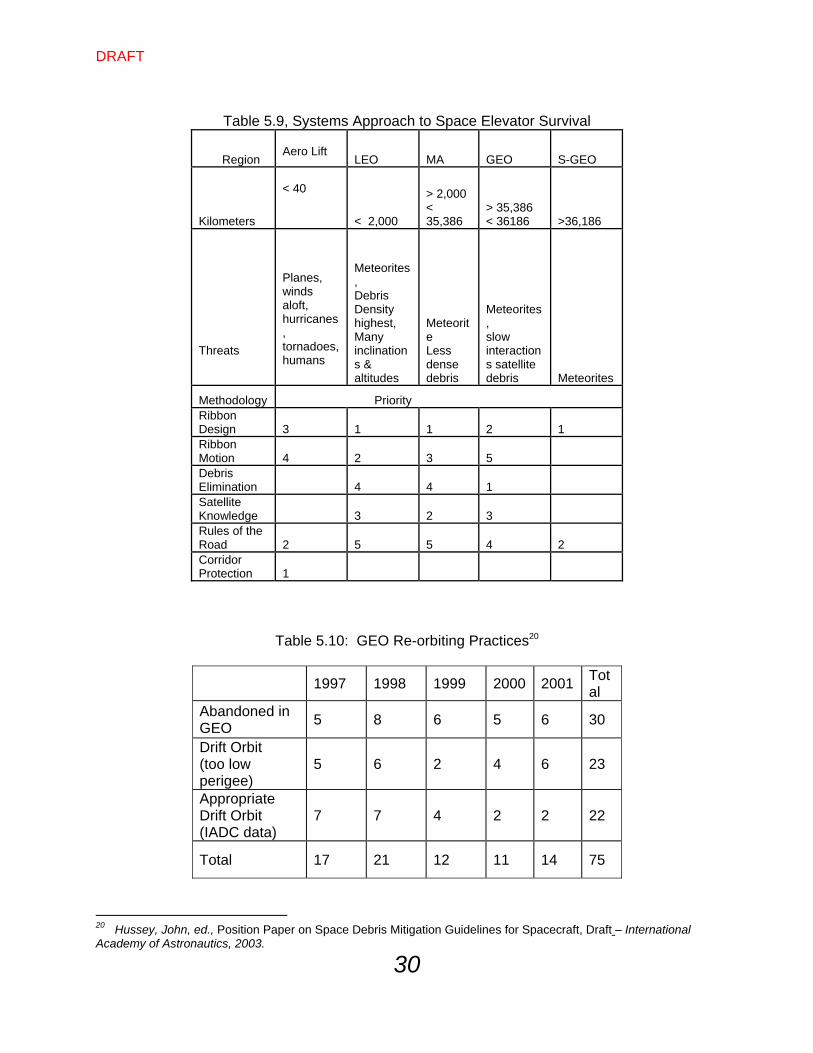
shows a proposed prioritization of mitigation approaches for each altitude region. Table 5.9 shows various approaches and sets a prioritization for a systems solution against debris, operational spacecraft, and meteors/meteorites. The order for the solution set is different for each altitude region because of the resultant system trades between region vs. threat vs. mitigation approach. Super GEO Priority # 1 Ribbon Design – The principle threat is micrometeorites. As such, a robust ribbon design solves most of the threat, ensuring survival through multiple hits per section per year enabling mission operation success. Priority # 2 Rules of the Road – The future of Super GEO satellites is going to be significantly different with easy and cheap access to that altitude. As such, the movement of old satellites to graveyard orbits will change to one of capturing old satellites (and, perhaps, using their mass as counterweight). GEO Priority # 1 Debris Elimination – The largest threat is collision with a large spacecraft or rocket body and a space elevator. Collection of GEO satellites not under operational control could help significantly reduce the probability of collision. In addition, this collection of mass could aid in counter weighting for a space elevator. Priority # 2 Ribbon Design – The meteorite threat is still significant and must be accounted for with ribbon design. Expectation of multiple hits per year will require a design robust enough to survive. Priority # 3 Satellite Knowledge – The GEO arc is not very well tracked because of marginal optical resolution to 37,000 km and needs improvements to see if there are threats from smaller components of older satellites. Perhaps, an in orbit sensor could enhance our knowledge; and/or, a sensor located on a space elevator. Priority # 4 Rules of the Road – Strengthen the GEO ITU rules to ensure no lost satellites or out of control inert bodies. Table 5.10 shows current orbital practices from 1997-2002, with only partial success at ensuring that satellites end up in this graveyard orbit. Only 22 satellites were in the appropriate drift orbits according to the International Agencies Debris Committee (IADC) report.
Priority # 5 Ribbon Motion – Dormant GEO satellites and high velocity GEO transfer orbit rocket bodies are large enough to sever the ribbon, but can be tracked, predicted, and avoided.
DRAFT
30
Table 5.9, Systems Approach to Space Elevator Survival
Region
Aero Lift
LEO MA GEO S-GEO
Kilometers
< 40
< 2,000
> 2,000 < 35,386
> 35,386 < 36186 >36,186
Threats
Planes, winds aloft, hurricanes, tornadoes, humans
Meteorites, Debris Density highest, Many inclinations & altitudes
Meteorite Less dense debris
Meteorites, slow interactions satellite debris Meteorites
Methodology
Priority Ribbon Design
3 1 1 2 1
Ribbon Motion
4 2 3 5
Debris Elimination
4 4 1
Satellite Knowledge
3 2 3
Rules of the Road
2 5 5 4 2
Corridor Protection
1
Table 5.10: GEO Re-orbiting Practices20
1997 1998 1999 2000 2001 Total
Abandoned in GEO
5 8 6 5 6 30
Drift Orbit (too low perigee)
5 6 2 4 6 23
Appropriate Drift Orbit (IADC data)
7 7 4 2 2 22
Total 17 21 12 11 14 75
20 Hussey, John, ed., Position Paper on Space Debris Mitigation Guidelines for Spacecraft, Draft – International Academy of Astronautics, 2003.
DRAFT
31
MA Priority # 1 Ribbon Design – As the MEO region starts just above LEO, and also has a large set of human made debris in the 12 hour orbit, the ability to survive space debris off rocket bodies and spacecraft must be considered. Priority # 2 Satellite Knowledge – As in the total area of space debris, better understanding of threats is important and can lead to better operational approaches to mitigate them. Priority # 3 Ribbon Motion – Dormant navigation satellites and high velocity GEO transfer orbit rocket bodies are large enough to sever the ribbon, but can be tracked, predicted, and avoided. Priority # 4 Debris Elimination – Larger pieces of debris in highly elliptical orbits, such as the GEO transfer orbit, are indeed a threat and can be de-orbited relatively easily by using atmospheric drag at perigee. Priority # 5 Rules of the Road – The MEO orbit is very important for today’s navigation systems. As such, there will be multiple constellations at the “half way to GEO” location and large satellites must be controlled as harmonic orbits so they do not cross the equator at the precise location of the space elevator. LEO Priority # 1 Ribbon Design – Space engineers must assume that a ribbon will be impacted by small space debris and meteorites. As such, the design of a ribbon must be flexible enough to accept monthly (or weekly) hits and still be robust enough to function for its estimated lifetime of 50 years. The design of a ribbon can provide this capability through multiple strands of nanotubes, weave patterns, etc., maximizing longevity under these conditions. Priority # 2 Ribbon Motion – This combines with situational awareness to enable operational success. One key element in the concept is multiple base legs that can move the bottom of a single strand elevator by simply changing the length of each leg. The dynamics of space elevator motion can be predicted and incorporated with satellite location knowledge to assist in moving out of the way of large space debris items. Priority # 3 Satellite Knowledge – Operational approaches must be implemented for a set of debris mitigation techniques. By knowing the orbits of large space debris, a space elevator can be moved as required. To accomplish this, the precise orbital characteristics of space objects must be known. Priority # 4 Debris Elimination – This concept is an idea whose time has come. We must not only stop polluting our environment, but we must ensure a healthy one. This could very well be construed as a “environmental cleanup” activity. Priority # 5 Rules of the Road – The reality is that LEO satellites will be a staple of nations’ missions and will be circling the globe every 100 minutes or so. An extra requirement in the systems design set should lead to orbits that are periodic. As such, they could avoid the space elevator nodal location. An international Rules of the Road agreement can ensure that mission essential orbits can still be utilized, while maintaining a safe space elevator corridor. Aero Lift Priority # 1 Corridor Protection – Rules of the Road for flights, boating, and driving will ensure that the corridor does not suffer from accidental collisions. Priority #2 Rules of the Road – This is an extension of priority #1, but applied to the international arena similar to maritime law or aeronautical treaties. Priority #3 Ribbon Design – The ribbon must be designed for this unique transition from vacuum to sea level pressure. This transition through the various levels of atmospheric

DRAFT
32
pressure will be dynamic and stressful on the ribbon. However, the ribbon must be manufactured with the stated objective of “no failures” in whatever environment it is in. Priority #4 Ribbon Motion – This mitigation technique will be utilized when there is a predictable hazard that can be defeated by moving the ribbon legs across the surface of the Earth.
DRAFT
33
Chapter 5 – Conclusions Major work to be done here at the Space Elevator Conference Aug 2010 5.1 Summary: The From chapter 2 With these new debris particles in orbit, the calculations were run to assess the situation. The answer came back in two parts: Answer 1: We have crossed over from the position where doing nothing works – the Big Sky theory no longer is applicable as a policy. The space faring nations MUST act in more than a passive manner if LEO is to be of use to us in the future. Answer 2: Calculations showed that the environment is fragile and actions must be initiated. The estimate shows that five large bodies must be removed per year to alter the growing problem we have. Although a big rocket body only counts as a single piece of debris, it has the potential of exploding into thousands when hit by the expected future collisions with small debris. There are over 2,000 large pieces that should be removed to ensure that the cascade effect does not dominate the future environment. From Chapter 3 Probability of Collision Conclusions:
GEO is not a problem MEO is not a problem Untrackable, small (<10 cm) will impact the Space Elevator in (LEO 200-2000
Kms) once every 10 days on the average and therefore must be designed for impact velocities and energies.
Trackable debris will impact the total LEO segment (200 – 2000 kms) once per 100 days or multiple times a year if not accounted for.

DRAFT
34
Trackable debris will only impact a single 60 km stretch of LEO space elevator every 18 years on the average and every 5 years in the peak regions.
DRAFT
35
Major work to be done here at the Space Elevator Conference Aug 2010
Chapter 6 – Recommendations 6.1 Recommendations: The space elevator recommendations will be broken into the areas where the impact can be successful and significantly improve the survivability of the Space Elevator vs. Space Debris. 6.1.1 Space Elevator Community Determine best way to geolocate ribbon elements Design for small debris impacts (robust design, inspector, repair) Determine strategy for large debris avoidance Mitigate loss of single ribbon sever through multiple backup space elevators 6.1.2 Space Debris Community Establish more precision in tracking [Mature Loftus/Stansbery study on improving SSN tracking capabilities] Improve ephemeris propagation technology Establish excellent space situational awareness for all Mandate GPS on all future satellites Publicly announce debris/satellite and ribbon location(s) daily Establish “rules of the road” for the future Plan for debris removal made possible by space elevator and related technologies 6.1.3 Satellite Launcher and Operator Develop robust human transportation Continue debris minimization efforts Plan for use of ribbon for transport to orbit and removal from orbit at EOL 6.2 Concluding Thoughts The risk of collision of a tracked object with the space elevator is low but the consequence is high so it must be addressed. The primary mitigation technique is multiple ribbons. Once we overcome the gravity well we must ensure we always have a ribbon available to build another ribbon. The risk of collision with an untracked object is high but the
DRAFT
36
consequence is low. Periodic “inspect and repair as necessary” by a repair robot should preserve the capability of individual ribbons. 6.3 Another Perspective – Steps Fowards When it comes to international spectrum, the general rule is that new owner/operators must not interfere with the systems already in place (grandfathered). From a debris mitigation standpoint, it should be expected that the space elevator owner/operators must not interfere with existing systems, i.e., the space elevator shouldn’t pose a threat to current orbiting satellite systems. If we consider Iridium (66 satellites in the 774-784 km band) and use the aforementioned formula, Iridium would have a .055 PC with a single space elevator for a year. Since a maneuver of a couple kilometers would almost certainly disable the use of their crosslinks, Iridium would likely rather not perform such maneuvers. This probably means that the space elevator community needs to ensure their planned operation includes collision avoidance activities that do not include requiring existing systems to perform collision avoidance maneuvers. 6.3.1 Select a Baseline As a space elevator concept is strengthened by solid engineering and discussions are initiated over who will build what portions of the project, serious consideration and important engineering steps could be started. Selection of an open element baseline should include the previous analysis and robustly incorporate all the risk mitigation techniques. However, three timely initiatives are required for this systems approach:
Initiate “rules of the road” discussions Initiate a de-orbit capability Enhance “zero debris” position
Initiate “Rules of the Road” Discussions: As a space elevator project goes forward, space nations must recognize that it will not remain under regulated in space. Rules must be initiated that would enable a space elevator vertical corridor to exist. Control of nodal passing must be implemented around the world with a mature set of rules ensuring that a space elevator becomes reality. Initiate a De-Orbit Capability: Many papers and engineering concepts have surfaced that deal with elimination of current and future orbital debris. However, cost has always limited the activities to studies without follow-on engineering orbital tests. As a space elevator is funded and goes forward, investment in environmental cleanup should be included in all planning and funding requirements. An idea to initiate action could be to create a prize for the first organization to de-orbit a rocket body with a current estimated lifetime of ten years or more. The prize could be called the “Space Debris Enterprise Award.” In addition, follow-up action must be stimulated with rewards for de-orbiting debris that is hazardous to the future of space elevators. New debris must become at least as socially, and perhaps legally, unacceptable as is terrestrial pollution. Enhance a “Zero Debris” Position: Currently (2005) the International Academy of Astronautics is publishing a position paper on space debris.21 In that paper the Academy takes the position that it is the goal of all space faring nations to create zero space debris within the three important regions. The LEO, navigation constellation ring, and GEO belt are identified. To ensure a healthy space elevator, the concept must be broadened to include all orbits. The
21 Hussey, John ed., Paper on Space Debris Mitigation Guidelines for Spacecraft, Draft – International Academy of Astronautics, 2003.
DRAFT
37
mandatory implementation of Zero Debris Requirements would be early in a space systems design for programs with Preliminary Design Reviews after 2007. However, the positive impact on a space elevator and other future initiatives would be tremendous. 6.3.2 Initiatives: The final conclusion of a systems analysis for a space elevator that will survive debris, operational spacecraft, meteors and meteorites is:
Start the Initiatives NOW !
DRAFT
38
Major work to be done here at the Space Elevator Conference Aug 2010
Chapter 7 – Projections into the Future

DRAFT
39
whomever
Appendix References