RT 560 RT 820 - Wacker Neusonproducts.wackerneuson.com/manuals/Repair/88433_002Rep.pdf · rt 560 rt...
96
www.wackergroup.com Roller RT 560 RT 820 REPAIR MANUAL 0088433 002 0699 en 0 0 8 8 4 3 3
Transcript of RT 560 RT 820 - Wacker Neusonproducts.wackerneuson.com/manuals/Repair/88433_002Rep.pdf · rt 560 rt...
www.wackergroup.com
Roller
RT 560RT 820
REPAIR MANUAL
0088433 002
0699 en
0 0 8 8 4 3 3


1
RT 560/820
THE INFORMATION CONTAINED IN THIS MANUAL WAS BASED ON MACHINES IN PRODUCTION AT THE TIME OF PUBLICATION.WACKER CORPORATION RESERVES THE RIGHT TO CHANGE ANY PORTION OF THIS INFORMATION WITHOUT NOTICE.
Safety Messages
The procedures described in this manual containNOTES, CAUTIONS, and WARNINGS which must befollowed to prevent the possibility of improper service,damage to the equipment, or personal injury.
Notes: Notes appear in italics and contain additionalinformation important to a procedure.
CAUTION: Cautions provide information important toprevent errors which could damage machine or com-ponents.
Warnings inform of conditions or practices whichcould lead to personal injury or death!
WARNING
6594, 6784, 7166, 7167, 7506 - RT 5606595, 6785, 7172, 7173, 7507, 8047 - RT 820
This Manual covers machines withSerial Numbers beginning:
Operating Information
You must be familiar with the operation of this machinebefore you attempt to troubleshoot or make any repairsto it. Basic operating and maintenance procedures aredescribed in the owner's manual supplied with themachine. The owner's manual should be kept with themachine. If it becomes lost, please contact WACKERCorporation to order a replacement.
Damage caused by misuse or neglect of the unitshould be brought to the attention of the operator, toprevent similar occurrences from happening in thefuture.
Engine Repair Information
Service information for the engine is available in theengine manufacturer's owner and repair manuals. Theowner's manual was included with the machine at thetime of its shipment from the factory. The repair manu-al can be obtained from the engine manufacturer, or itcan be ordered through WACKER Corporation usingthe part number and description:
Lombardini Model 12LD Repair ManualWACKER P/N 85095
Engine manuals are dependent on the manufacturer'ssupply and prices in effect at time of order. Informationcontained in these manuals is the sole responsibility ofthe engine manufacturer, unless otherwise specified.
Parts Information
A Parts Manual was supplied with the machine at thetime of its shipment from the factory. Replacementcopies are available by contacting WACKER Corpora-tion. Please supply machine serial number when or-dering manuals.
INTRODUCTION
2
RT 560/820
80809 MÜNCHEN DEUTSCHLAND
MADE IN USA
MENOMONEE FALLS WI USA 53052
kW
hp
kg
dB(A)/7m
lbs
88223
Serial Number
Production Sequence
Model Identification
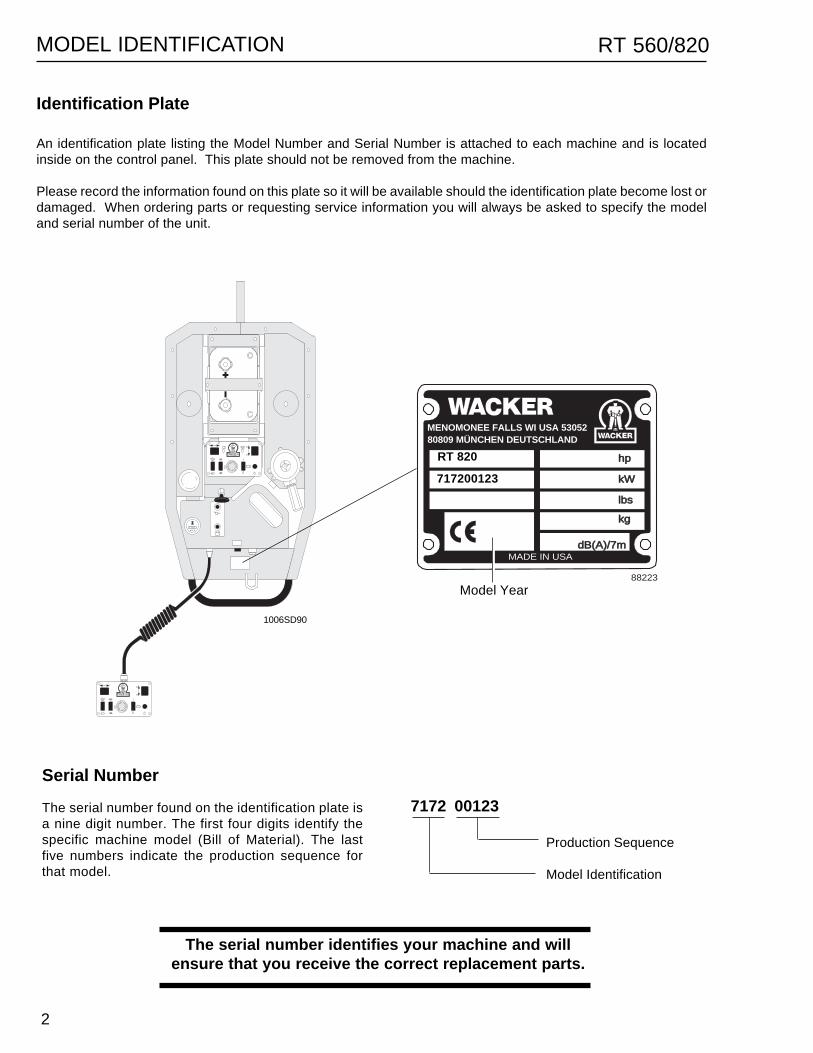
7172 00123The serial number found on the identification plate isa nine digit number. The first four digits identify thespecific machine model (Bill of Material). The lastfive numbers indicate the production sequence forthat model.
An identification plate listing the Model Number and Serial Number is attached to each machine and is locatedinside on the control panel. This plate should not be removed from the machine.
Please record the information found on this plate so it will be available should the identification plate become lost ordamaged. When ordering parts or requesting service information you will always be asked to specify the modeland serial number of the unit.
1006SD90
Identification Plate
MODEL IDENTIFICATION
RT 820
717200123
Model Year
The serial number identifies your machine and willensure that you receive the correct replacement parts.

3
RT 560/820 TABLE OF CONTENTS
UNIT 1 - SAFETY1.1 General Precautions ......................................................................................... 1-11.2 Operating Safety .............................................................................................. 1-21.3 Engine Safety ................................................................................................... 1-21.4 Service & Repair Safety ................................................................................... 1-31.5 Lifting Machine ................................................................................................. 1-3
UNIT 2 - GENERAL2.1 Engine Specifications ....................................................................................... 2-12.2 Roller Specifications ......................................................................................... 2-22.3 Lubrication Specifications ................................................................................. 2-22.4 Hydraulic Pressures ......................................................................................... 2-22.5 Operating Systems .......................................................................................... 2-32.6 Reference Numbers ( ) .................................................................................... 2-32.7 Replacement Parts ........................................................................................... 2-32.8 Controls & Service Locations ........................................................................... 2-42.9 General Operation ............................................................................................ 2-62.10 Exciter Operation .............................................................................................. 2-72.11 Engine Speed & Machine Performance ............................................................ 2-8
UNIT 3 - HYDRAULIC SYSTEM3.1 Hydraulic System Cleanliness .......................................................................... 3-13.2 Hydraulic Oil Requirements .............................................................................. 3-13.3 Hydraulic Flow Diagram.................................................................................... 3-23.4 Hydraulic System ............................................................................................. 3-33.5 Control Valve Block .......................................................................................... 3-43.6 Hydraulic Schematic ......................................................................................... 3-53.7 High Speed Travel Circuit ................................................................................. 3-63.8 Low Speed Travel Circuit ................................................................................. 3-83.9 Exciter Circuit ................................................................................................. 3-103.10 Steering Circuit ............................................................................................... 3-123.11 Checking Hydraulic Pressures........................................................................ 3-143.12 Checking Drive Circuit .................................................................................... 3-143.13 Checking Vibration Circuit .............................................................................. 3-153.14 Checking Steering Circuit ............................................................................... 3-163.15 Testing Drive & Exciter Circuit Relief Valves .................................................. 3-163.16 System Pressures .......................................................................................... 3-163.17 Hydraulic Hose Routing and Location ............................................................ 3-18
UNIT 4 - DRUM4.1 Introduction ....................................................................................................... 4-14.2 Changing Oil ..................................................................................................... 4-14.3 Drum Assembly - Exploded View ..................................................................... 4-24.4 Drums ............................................................................................................... 4-34.5 Drum Support Cover ........................................................................................ 4-44.6 Drive Bearings & Seals ..................................................................................... 4-54.7 Drivecase ......................................................................................................... 4-64.8 Drivecase - Exploded View ............................................................................... 4-74.9 Brake (S/N 7100 00000 & Above) .................................................................... 4-84.10 Servicing Brake ................................................................................................ 4-94.11 Drive Motor ..................................................................................................... 4-104.12 Drivecase Components .................................................................................. 4-11
4
RT 560/820
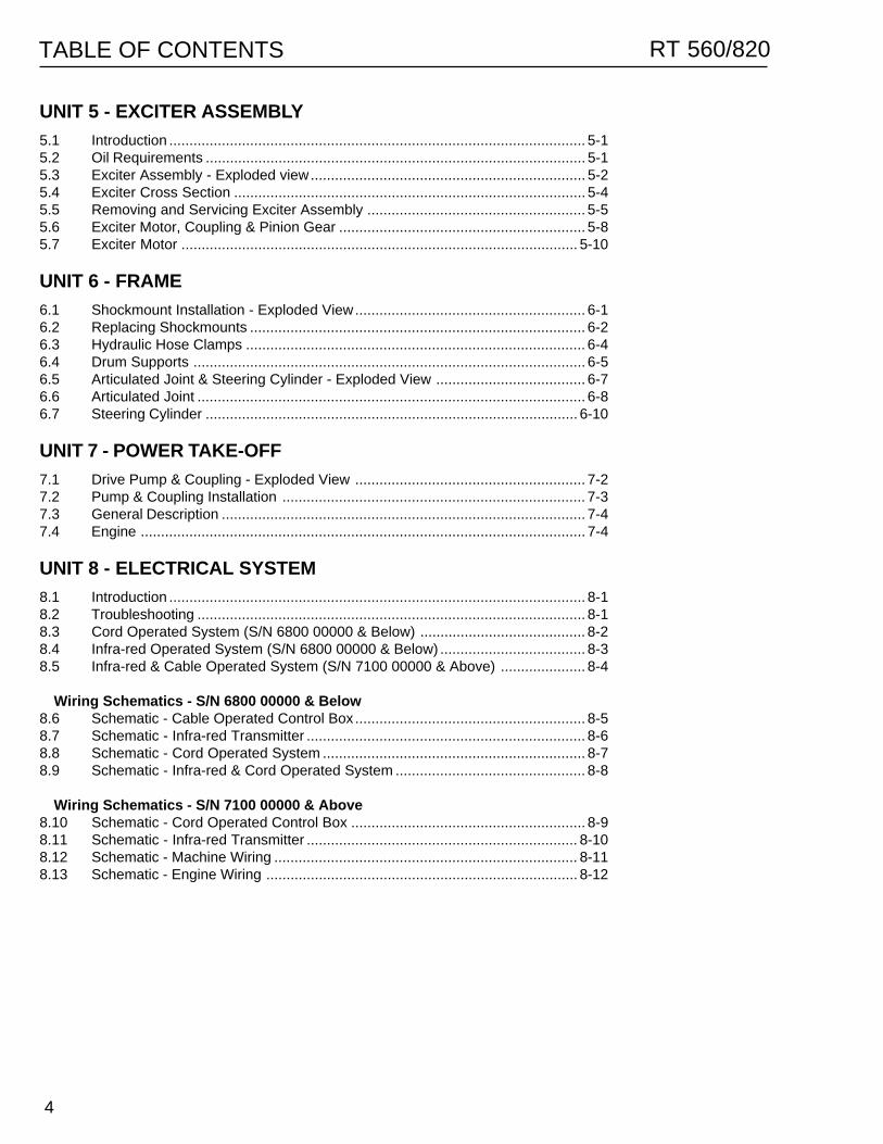
UNIT 5 - EXCITER ASSEMBLY5.1 Introduction ....................................................................................................... 5-15.2 Oil Requirements .............................................................................................. 5-15.3 Exciter Assembly - Exploded view.................................................................... 5-25.4 Exciter Cross Section ....................................................................................... 5-45.5 Removing and Servicing Exciter Assembly ...................................................... 5-55.6 Exciter Motor, Coupling & Pinion Gear ............................................................. 5-85.7 Exciter Motor .................................................................................................. 5-10
UNIT 6 - FRAME6.1 Shockmount Installation - Exploded View......................................................... 6-16.2 Replacing Shockmounts ................................................................................... 6-26.3 Hydraulic Hose Clamps .................................................................................... 6-46.4 Drum Supports ................................................................................................. 6-56.5 Articulated Joint & Steering Cylinder - Exploded View ..................................... 6-76.6 Articulated Joint ................................................................................................ 6-86.7 Steering Cylinder ............................................................................................ 6-10
UNIT 7 - POWER TAKE-OFF7.1 Drive Pump & Coupling - Exploded View ......................................................... 7-27.2 Pump & Coupling Installation ........................................................................... 7-37.3 General Description .......................................................................................... 7-47.4 Engine .............................................................................................................. 7-4
UNIT 8 - ELECTRICAL SYSTEM8.1 Introduction ....................................................................................................... 8-18.2 Troubleshooting ................................................................................................ 8-18.3 Cord Operated System (S/N 6800 00000 & Below) ......................................... 8-28.4 Infra-red Operated System (S/N 6800 00000 & Below) .................................... 8-38.5 Infra-red & Cable Operated System (S/N 7100 00000 & Above) ..................... 8-4
Wiring Schematics - S/N 6800 00000 & Below8.6 Schematic - Cable Operated Control Box ......................................................... 8-58.7 Schematic - Infra-red Transmitter ..................................................................... 8-68.8 Schematic - Cord Operated System ................................................................. 8-78.9 Schematic - Infra-red & Cord Operated System ............................................... 8-8
Wiring Schematics - S/N 7100 00000 & Above8.10 Schematic - Cord Operated Control Box .......................................................... 8-98.11 Schematic - Infra-red Transmitter ................................................................... 8-108.12 Schematic - Machine Wiring ........................................................................... 8-118.13 Schematic - Engine Wiring ............................................................................. 8-12
TABLE OF CONTENTS
1- 1
SAFETY 1RT 560/820
1.1 General Precautions
For your protection, the protection of others, and to prevent damage to the unit, read, understand, and follow allsafety instructions. Failure to follow the safety notes listed below could cause damage to the equipment or resultin personal injury.
ALWAYS dress appropriately for job conditions andwear specified safety devices such as a hard hat,goggles, and ear protection where required.
ALWAYS keep hands, feet, and clothing away frommoving parts when operating or servicing equipment.
ALWAYS turn engine off when leaving machine unat-tended.
ALWAYS drain fuel tank when transporting machinelong distances.
ALWAYS replace all missing and hard-to-read decals.
ALWAYS check and tighten all external fasteners atregular intervals.
NEVER allow unfamiliar or inexperienced personnelto operate the machine.
NEVER operate a unit in need of service or repairexcept for service testing.
NEVER operate a unit with a safety device or guardremoved.
NEVER operate with fuel cap loose or missing.
NEVER leave machine running unattended.
NEVER modify the equipment without express writtenapproval of the manufacturer.
NEVER run machine indoors or in areas with limitedventilation unless sufficient ventilation or exhausthoses can be provided.
UNIT 1
SAFETY
1.1 General Precautions .............................................................................. 1-11.2 Operating Safety ................................................................................... 1-21.3 Engine Safety ........................................................................................ 1-21.4 Service & Repair Safety ........................................................................ 1-31.5 Lifting Machine ...................................................................................... 1-3
1- 2
1 SAFETY RT 560/820
1.2 Operating Safety
WARNING
Familiarity and proper training are required for the safe operation of mechanical equipment !
Equipment operated improperly or by untrained personnel can be dangerous! Read the operating instructionsand familiarize yourself with the location and use of all controls before attempting to operate or repair thisequipment. An inexperienced operator should receive instruction from someone familiar with the equipmentbefore being allowed to operate it.
Before starting and while operating machine:
1. Make sure all safety devices and guards are inplace before starting machine! Do not operatemachine with safety devices or guards missingor inoperative.
2. Immediately after start-up, check that all con-trols are functioning properly! Do not operatemachine unless all controls operate correctly.
3. Check that articulated joint lock is released andproperly stored before operating machine! Ma-chine cannot be steered when lock is set.
4. If machine must be parked on an incline, blockdrums to prevent rolling.
5. Look behind you when operating roller in reverse!Never assume it is clear behind you.
6. Remain aware of the changing positions andmovement of other equipment and personnel onthe jobsite!
1.3 Engine Safety
Internal combustion engines present special hazards during operation and fueling. Failure to follow the safetypractices described below could result in severe injury or death.
WARNING
DO NOT operate engine in an enclosed area or anarea with limited ventilation. Exhaust fumes containcarbon monoxide, a deadly gas!
DO NOT fill tank near open flame or while smoking!
DO NOT fill fuel tank if engine is hot or while engineis running!
DO NOT spill fuel while filling tank or run engine if anodor of fuel is present! If fuel is spilled, wait until ithas evaporated or move the machine away from thespill before running engine!
DO NOT touch or lean against hot exhaust pipes orengine cylinder!
1- 3
SAFETY 1RT 560/820
WARNING
BEFORE attempting to lift or jack up this ma-chine, engage the locking device at the articu-lated joint! This will prevent the front and rearmachine halves from swinging together. Failureto lock joint could result in a serious crushinginjury! See Section 1.5.
DO NOT open hydraulic lines or loosen hy-draulic connections while engine is running!Hydraulic fluid under pressure can penetrate theskin, cause burns, blind you, or create otherpotentially dangerous hazards. Set all controls inneutral and turn engine off before loosening hy-draulic fittings or attaching test gauges.
1.4 Service & Repair Safety
The service procedures contained in this manual are intended for use by an individual equipped with the propertools and equipment, and familiar with safe shop practices.
Should questions arise during the service or repair of this equipment, please contact your area WACKERCorporation Service Department for assistance! WACKER Corporation maintains a staff of trained servicespecialists to answer your questions and provide assistance and training.
WARNING
1.5 Lifting Machine
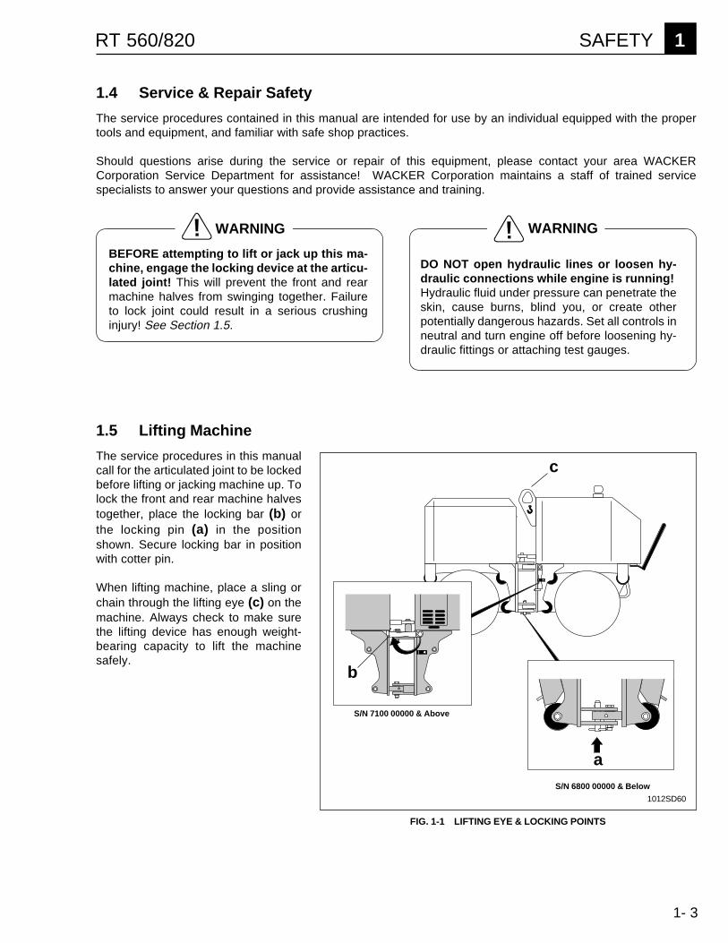
The service procedures in this manualcall for the articulated joint to be lockedbefore lifting or jacking machine up. Tolock the front and rear machine halvestogether, place the locking bar (b) orthe locking pin (a) in the positionshown. Secure locking bar in positionwith cotter pin.
When lifting machine, place a sling orchain through the lifting eye (c) on themachine. Always check to make surethe lifting device has enough weight-bearing capacity to lift the machinesafely.
S/N 6800 00000 & Below
S/N 7100 00000 & Above
a
b
c
1012SD60
FIG. 1-1 LIFTING EYE & LOCKING POINTS

1- 4
1 SAFETY RT 560/820
NOTES
2-1
GENERAL 2RT 560/820
UNIT 2
General2.1 Engine Specifications ............................................................................ 2-12.2 Roller Specifications .............................................................................. 2-22.3 Lubrication Specifications ...................................................................... 2-22.4 Hydraulic Pressures .............................................................................. 2-22.5 Operating Systems ............................................................................... 2-32.6 Reference Numbers ( ) ......................................................................... 2-32.7 Replacement Parts ................................................................................ 2-32.8 Controls & Service Locations ................................................................ 2-42.9 General Operation ................................................................................. 2-62.10 Exciter Operation ................................................................................... 2-72.11 Engine Speed & Machine Performance................................................. 2-8
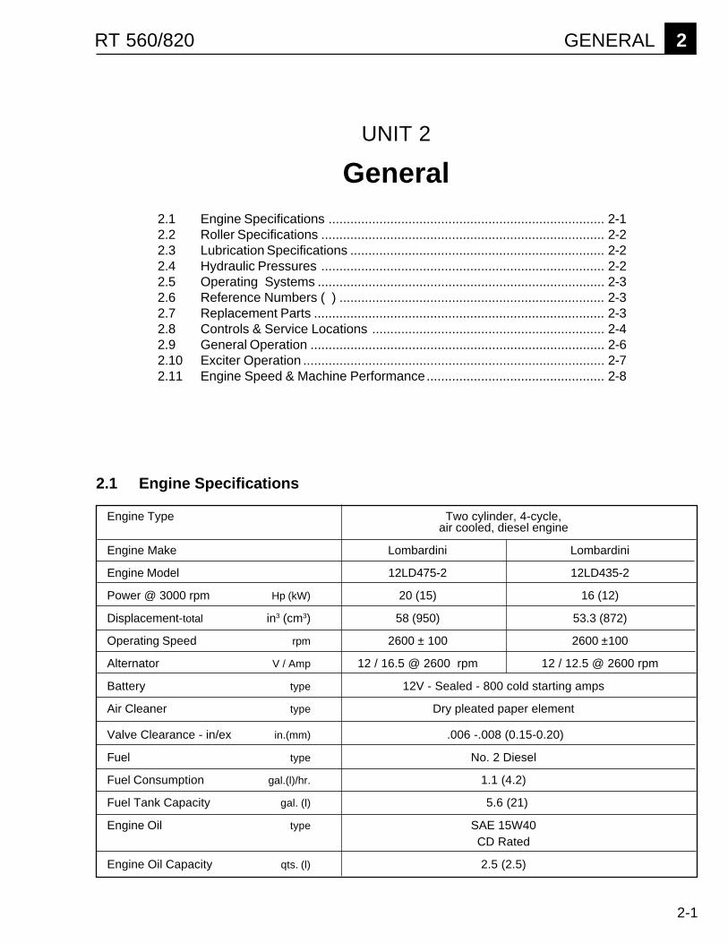
Engine Type Two cylinder, 4-cycle,air cooled, diesel engine
Engine Make Lombardini Lombardini
Engine Model 12LD475-2 12LD435-2
Power @ 3000 rpm Hp (kW) 20 (15) 16 (12)
Displacement-total in3 (cm3) 58 (950) 53.3 (872)
Operating Speed rpm 2600 ± 100 2600 ±100
Alternator V / Amp 12 / 16.5 @ 2600 rpm 12 / 12.5 @ 2600 rpm
Battery type 12V - Sealed - 800 cold starting amps
Air Cleaner type Dry pleated paper element
Valve Clearance - in/ex in.(mm) .006 -.008 (0.15-0.20)
Fuel type No. 2 Diesel
Fuel Consumption gal.(l)/hr. 1.1 (4.2)
Fuel Tank Capacity gal. (l) 5.6 (21)
Engine Oil type SAE 15W40CD Rated
Engine Oil Capacity qts. (l) 2.5 (2.5)
2.1 Engine Specifications

2-2
2 GENERAL RT 560/820
Normal Operating Relief Valve TestPressure @ 2600 RPM Pressure Port
PSI (mPa) 1 PSI (mPa) Location
Forward or Reverse 180 - 600 (1.2 - 4.2) 3000 (21) Rear Pumpin LOW Speed
Forward or Reverse 300 - 800 (2.1 - 5.6) 3000 (21) Front Pumpin HIGH Speed
Exciter in 1050 - 1250 (7.3 - 8.7) 3000 (21) Front PumpLOW Vibration
Exciter in 1200 - 1600 (8.4 - 11.2) 3000 (21) Front PumpHIGH Vibration
Steering 300 - 800 (2.1 - 5.6) 1000 (7) Rear Pump300 - 1200 (2.1 - 8.4) Front Pump
1 Refer to Unit 3 - Hydraulic System. Pressure readings will be higher when operating in loose soil or when on an incline. Pressure readingswill be ower when operating on a flat, hard surface.
2.2 Roller SpecificationsRT 560 RT 820
Overall Dimensions (l x w x h) in. 80 x 22 x 48 80 x 32 x 48(mm) (2030 x 560 x 1220) (2030 x 820 x 1220)
Operating Weight lb.(kg) 2830 (1283 ) 3020 (1370)
Area Capacity ft2 (m2) / hr. 7500 (690) 10900 (1016)
Inside Turning Radius in. (m) 63 (1.6) 58 (1.5)
Low Speed ft. (m)/min. 68 (21)
High Speed ft. (m)/min. 136 (41)
Vibration Frequency vpm (Hz) 2400 (40)
Gradeability with vibration % 50
Gradeability without vibration % 55
2.4 Hydraulic Pressures
Type Quantity
Hydraulic System SAE 10W30 - Hydraulic Fluid 10.5 gal. (40 litres)
Exciter SAE 10W30 32 oz. (950 ml)
Drum Drive Gearcase SAE 10W30 8 oz. (240 ml)
Articulated Joint Shell Alvania No. 2 As required
Steering Cylinder Shell Alvania No. 2 As required
2.3 Lubrication Specifications

2-3
GENERAL 2RT 560/820
2.5 Operating Controls
There are two types of operating controls in use on theRT Roller.
1. Serial numbers beginning 6594, 6595, 6784, 6785use a Joystick Control. This system uses a singlejoystick controller (a) to control machine move-ment.
2. Serial numbers beginning 7166, 7167, 7172, 7173,7506, 7507 use a Dual Lever Control. This systemfeatures two separate switches (b) to control ma-chine movement and includes an emergency stopbutton (c). Additional features provided on theseunits include an oil cooler and hydraulic parkingbrake.
Machine versions can be identified by the type ofcontrol box being used, as well as by the serial numberof the unit. When following repair instructions or callingfor information know the serial number of the unit.
See Section 2.8 - Controls and Service Locations formore detailed machine identification.
2.7 Replacement Parts
The repair procedures contained in this manual do notinclude part numbers. For parts replacement informa-tion, refer to the Parts Manual included with the ma-chine. When ordering replacement parts, please listmodel and serial number of machine.
a
S/N 6800 00000& Below
FIG. 2-1 IDENTIFYING OPERATING SYSTEMS2.6 Reference Numbers ( )
Repair procedures may contain reference numbersenclosed in parentheses ( ). These numbers refer tothe item numbers shown on the assembly drawingslocated within that repair section. They are included toaid the mechanic in identifying parts and assemblingcomponents.
�������
��
���
������
��
�
S/N 7100 00000& Abovec
b
1012SD61
2-4
2 GENERAL RT 560/820
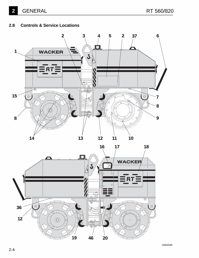
2.8 Controls & Service Locations
8
9
1
2 3
10111314 12
16 17
15
25
1006SD89
8
20
4 37 6
18
36
12
19 46
7
2-5
GENERAL 2RT 560/820
���
���
45
42
4140
39
35
26
25
24
23
38
22
21
28
29
30
31
34 33 32
27
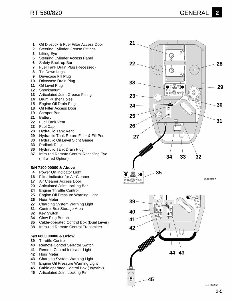
1 Oil Dipstick & Fuel Filter Access Door2 Steering Cylinder Grease Fittings3 Lifting Eye5 Steering Cylinder Access Panel6 Safety Back-up Bar7 Fuel Tank Drain Plug (Recessed)8 Tie Down Lugs9 Drivecase Fill Plug
10 Drivecase Drain Plug11 Oil Level Plug12 Shockmount13 Articulated Joint Grease Fitting14 Drum Pusher Holes15 Engine Oil Drain Plug18 Oil Filter Access Door19 Scraper Bar21 Battery22 Fuel Tank Vent23 Fuel Cap28 Hydraulic Tank Vent29 Hydraulic Tank Return Filter & Fill Port30 Hydraulic Oil Level Sight Gauge33 Padlock Ring36 Hydraulic Tank Drain Plug37 Infra-red Remote Control Receiving Eye
(Infra-red Option)
S/N 7100 00000 & Above4 Power On Indicator Light
16 Filter Indicator for Air Cleaner17 Air Cleaner Access Door20 Articulated Joint Locking Bar24 Engine Throttle Control25 Engine Oil Pressure Warning Light26 Hour Meter27 Charging System Warning Light31 Control Box Storage Area32 Key Switch34 Glow Plug Button35 Cable-operated Control Box (Dual Lever)38 Infra-red Remote Control Transmitter
S/N 6800 00000 & Below39 Throttle Control40 Remote Control Selector Switch41 Remote Control Indicator Light42 Hour Meter43 Charging System Warning Light44 Engine Oil Pressure Warning Light45 Cable operated Control Box (Joystick)46 Articulated Joint Locking Pin
1009SD92
1012SD62
44 43
2-6
2 GENERAL RT 560/820
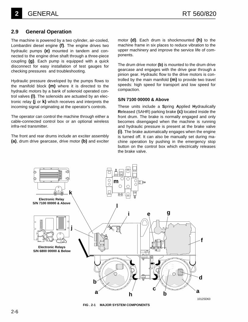
2.9 General Operation
The machine is powered by a two cylinder, air-cooled,Lombardini diesel engine (f). The engine drives twohydraulic pumps (e) mounted in tandem and con-nected to the engine drive shaft through a three-piececoupling (g). Each pump is equipped with a quickdisconnect for easy installation of test gauges forchecking pressures and troubleshooting.
Hydraulic pressure developed by the pumps flows tothe manifold block (m) where it is directed to thehydraulic motors by a bank of solenoid operated con-trol valves (l). The solenoids are actuated by an elec-tronic relay (j or k) which receives and interprets theincoming signal originating at the operator's controls.
The operator can control the machine through either acable-connected control box or an optional wirelessinfra-red transmitter.
The front and rear drums include an exciter assembly(a), drum drive gearcase, drive motor (b) and exciter
FIG . 2-1 MAJOR SYSTEM COMPONENTS
a
d
e
f
a
bc
bh
j
k
i
Electronic RelayS/N 7100 00000 & Above
Electronic RelaysS/N 6800 00000 & Below
1012SD63
motor (d). Each drum is shockmounted (h) to themachine frame in six places to reduce vibration to theupper machinery and improve the service life of com-ponents.
The drum drive motor (b) is mounted to the drum drivegearcase and engages with the drive gear through apinion gear. Hydraulic flow to the drive motors is con-trolled by the main manifold (m) to provide two travelspeeds: high speed for transport and low speed forcompaction.
S/N 7100 00000 & Above
These units include a Spring Applied HydraulicallyReleased (SAHR) parking brake (c) located inside thefront drum. The brake is normally engaged and onlybecomes disengaged when the machine is runningand hydraulic pressure is present at the brake valve(i). The brake automatically engages when the engineis turned off. It can also be manually set during ma-chine operation by pushing in the emergency stopbutton on the control box which electrically releasesthe brake valve.
m
gl
2-7
GENERAL 2RT 560/820
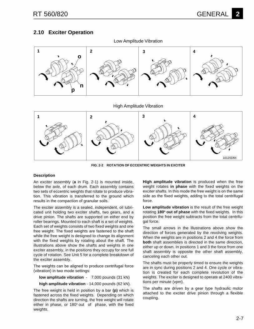
2.10 Exciter Operation
1 2 3 4
1 2 3 4
np
Low Amplitude Vibration
High Amplitude Vibration
FIG. 2-2 ROTATION OF ECCENTRIC WEIGHTS IN EXCITER
o
1012SD64
High amplitude vibration is produced when the freeweight rotates in phase with the fixed weights on theexciter shafts. In this mode the free weight is on the sameside as the fixed weights, adding to the total centrifugalforce.
Low amplitude vibration is the result of the free weightrotating 180o out of phase with the fixed weights. In thisposition the free weight subtracts from the total centrifu-gal force.
The small arrows in the illustrations above show thedirection of forces generated by the revolving weights.When the weights are in positions 2 and 4 the force fromboth shaft assemblies is directed in the same direction,either up or down. In positions 1 and 3 the force from oneshaft assembly is opposite the other shaft assembly,canceling each other out.
The shafts must be properly timed to ensure the weightsare in sync during positions 2 and 4. One cycle or vibra-tion is created for each complete revolution of theweights. The exciter is designed to operate at 2400 vibra-tions per minute (vpm).
The shafts are driven by a gear type hydraulic motorattached to the exciter drive pinion through a flexiblecoupling.
Description
An exciter assembly (a in Fig. 2-1) is mounted inside,below the axle, of each drum. Each assembly containstwo sets of eccentric weights that rotate to produce vibra-tion. This vibration is transferred to the ground whichresults in the compaction of granular soils.
The exciter assembly is a sealed, independent, oil lubri-cated unit holding two exciter shafts, two gears, and adrive pinion. The shafts are supported on either end byroller bearings. Mounted to each shaft is a set of weights.Each set of weights consists of two fixed weights and onefree weight. The fixed weights are fastened to the shaftwhile the free weight is designed to change its alignmentwith the fixed weights by rotating about the shaft. Theillustrations above show the shafts and weights in oneexciter assembly, in the positions they occupy for one fullcycle of rotation. See Unit 5 for a complete breakdown ofthe exciter assembly.
The weights can be aligned to produce centrifugal force(vibration) in two mode settings:
low amplitude vibration - 7,000 pounds (31 kN)
high amplitude vibration - 14,000 pounds (62 kN).
The free weight is held in position by a bar (p) which isfastened across the fixed weights. Depending on whichdirection the shafts are turning, the free weight will rotateeither in phase, or 180o out of phase, with the fixedweights.
2-8
2 GENERAL RT 560/820
2.11 Engine Speed & Machine Performance
Engine speed directly affects machine performance.The machine is designed to run at an engine speed of2600 rpm to produce the best results.
These machines use fixed displacement pumps andmotors. This means that as engine speed rises or falls,hydraulic flow through the pumps and to the motorsincreases or decreases.
Exciter speed (vpm) is determined by the amount offlow through the motors. If flow increases, exciterspeed rises. If flow decreases, exciter speed falls.
Even a small rise or fall in speed has a large affect onthe centrifugal force generated by the exciter. If theengine overspeeds even slightly, centrifugal force inthe exciter will increase significantly and can overloadthe exciter bearings. If the engine runs underspeed,the centrifugal force will drop dramatically, causingpoor compaction.
Low engine speed will also limit flow to the drivemotors, reducing travel speeds.
For optimum machine performance maintain enginespeed at 2600 rpm. Check engine speed accurately,using a tachometer, at regular intervals.

HYDRAULIC SYSTEM 3RT 560/820
3-1
UNIT 3
HYDRAULIC SYSTEM3.1 Hydraulic System Cleanliness .......................................................................... 3-13.2 Hydraulic Oil Requirements .............................................................................. 3-13.3 Hydraulic Flow Diagram.................................................................................... 3-23.4 Hydraulic System ............................................................................................. 3-33.5 Control Valve Block .......................................................................................... 3-43.6 Hydraulic Schematic ......................................................................................... 3-53.7 High Speed Travel Circuit ................................................................................. 3-63.8 Low Speed Travel Circuit ................................................................................. 3-83.9 Exciter Circuit ................................................................................................. 3-103.10 Steering Circuit ............................................................................................... 3-123.11 Checking Hydraulic Pressures........................................................................ 3-143.12 Checking Drive Circuit .................................................................................... 3-143.13 Checking Vibration Circuit .............................................................................. 3-153.14 Checking Steering Circuit ............................................................................... 3-163.15 Testing Drive & Exciter Circuit Relief Valves .................................................. 3-163.16 System Pressures .......................................................................................... 3-163.17 Hydraulic Hose Routing and Location ............................................................ 3-18
3.1 Hydraulic System Cleanliness
Keeping the hydraulic fluid clean is a vital factor affect-ing the service life of hydraulic components. Oil inhydraulic systems is used not only to transfer power,but also to lubricate the hydraulic components used inthe system. Keeping the hydraulic system clean willhelp avoid costly downtime and repairs.
Major sources of hydraulic system contaminationinclude:
1. Particles of dirt introduced when the hydraulic sys-tem is opened for maintenance or repair.
2. Contaminants generated by the mechanical com-ponents of the system during operation.
3. Improper storage and handling of hydraulic fluid.
4. Use of the wrong type of hydraulic fluid.
5. Leakage in lines and fittings.
To minimize hydraulic fluid contamination:
CLEAN hydraulic connections before opening lines.When adding oil, clean hydraulic tank filler cap andsurrounding area before removing.
AVOID opening pumps, motors or hose connectionsunless absolutely necessary.
PLUG or cap all open hydraulic connections whileservicing system.
CHANGE hydraulic filters and fluids at the recom-mended service intervals.
3.2 Hydraulic Oil Requirements
WACKER recommends the use of a good petroleum-based, anti-wear hydraulic oil in the hydraulic systemof this equipment. Good anti-wear hydraulic oils con-tain special additives to reduce oxidation, preventfoaming and provide for good water separation.
Most hydraulic oils are available in different viscosi-ties. The SAE number for an oil is used strictly toidentify viscosity—it does not indicate the type of oil(engine, hydraulic, gear, etc.).
Premium grade, Anti-wear hydraulic fluid Viscosity Rating - 10W30
See Section 2.3, Lubrication Specs., for Quantity

3 HYDRAULIC SYSTEM RT 560/820
3-2
3.3 Hydraulic Flow Diagram
* Used only on machines with serial numbers above 7100 00000.
P1
P2
E
F
Motor Case DrainsHigh Pressure LinesSupply Line
Return Lines
c
d
f
o
a b
e
g
h
i
j k
l
m
np
q
r
1012SD65
a SUCTION STRAINERb RETURN LINE FILTERc HYDRAULIC TANKd FRONT PUMPe REAR PUMPf OIL COOLER
g STEERING CYLINDERh BRAKE VALVEi VIBRATION VALVEj MAIN MANIFOLDk TRAVEL VALVEl STEERING VALVE
m CHECK VALVEn FRONT EXCITER MOTORo FRONT DRIVE MOTORp BRAKE ASSEMBLYq REAR DRIVE MOTORr REAR EXCITER MOTOR*
**
*

HYDRAULIC SYSTEM 3RT 560/820
3-3
3.4 Hydraulic System
Description
Refer to Hydraulic Flow Diagram on opposite page.
Pressure in the hydraulic system is generated by twogear pumps mounted in tandem to the back of theengine. The pumps are driven by a common shaftwhich is connected to the engine crankshaft through athree piece coupling. Capacity of the front pump (d) isapproximately 8 gpm (32 l/m) and is used to operatevibration or high speed travel. Rear pump (e) capacityis about 4 gpm (16 l/m) and is used for low speedtravel.
A control valve block directs oil flow from the pumps tothe motors and steering cylinder. The control valveblock is mounted beneath the control panel at the rearof the machine. It consists of the manifold (j), vibration(i), travel (k) and steering (l) valves. These valves aresolenoid operated. During operation the solenoids re-spond to the electrical signals being transmitted by theoperator from the control box. Two reliefs, located onthe main manifold, limit exciter and drive pressures to3000 PSI (21 mPa). The steering circuit relief ismounted on the steering valve and is set at 1000 PSI(7 mPa). See Section 3.5, Control Valve Block, forcontrol valve components.
Oil from the hydraulic tank (c) flows through a suctionstrainer (a) before it is drawn into the pump suctionport. The suction strainer is mounted in the tank and ismagnetic for removing metal particles. Hoses connectthe output ports of the pumps to the main manifold (j)on the control block. The main manifold directs oil flowinto the vibration (i) and travel (k) valves. Thesevalves in turn supply hydraulic pressure to operate theexciter and drive motors.
When operating in low speed travel, the larger frontpump is used to operate the exciter motors (n, r), thesmaller rear pump is used to operate the drive motors(o, q). When operating in high speed travel, the mainmanifold redirects front pump oil flow away from theexciter motors to the drive motors. Flow from the rearpump is directed back to the tank. In high speed travelthe exciter motors do not operate. See later sections inthis unit for a detailed description of the exciter anddrive circuits.
Return oil from the drive circuit flows to the steeringvalve (l) which directs it to the steering cylinder (g).
The hydraulic system is protected by a return line filter(b). The return line filter removes particles down to 10microns and includes a by-pass for cold weather start-up.
Brake & Oil Cooler
An oil cooler (f) and brake (p) were added to machineswith serial numbers above 7100 00000. On these unitsreturn flow from the steering valve is directed through acheck valve (m) to the oil cooler (f) before returning tothe hydraulic tank.
These units also utilize a hydraulic brake (p) on thefront drum. The brake is connected to the hydraulicsystem through the main manifold (j) and brake valve(h). The brake is spring loaded and normally set whenthe machine is off. When the hydraulic system is pres-surized the brake is automatically released. The brakecan be set manually by pressing the emergency stopbutton on the control box. This activates the solenoidon the brake valve (h) and releases the hydraulicpressure to the brake.
3 HYDRAULIC SYSTEM RT 560/820
3-4
��
��
�
�
� �����������������������
���������������������������
��������������������������
�����������������
������������������������
�����������������
�����������������
�������������������
�����������������
����������������
�� ��������������������������
���������������������������
����������������
��������������������������������
�� ��������������
��������������������
����������
����
����������
����������
���������
����������
�����������
��� ��� ���������
�����������������������������
��������!����������"�#$�%&'�
�����������������
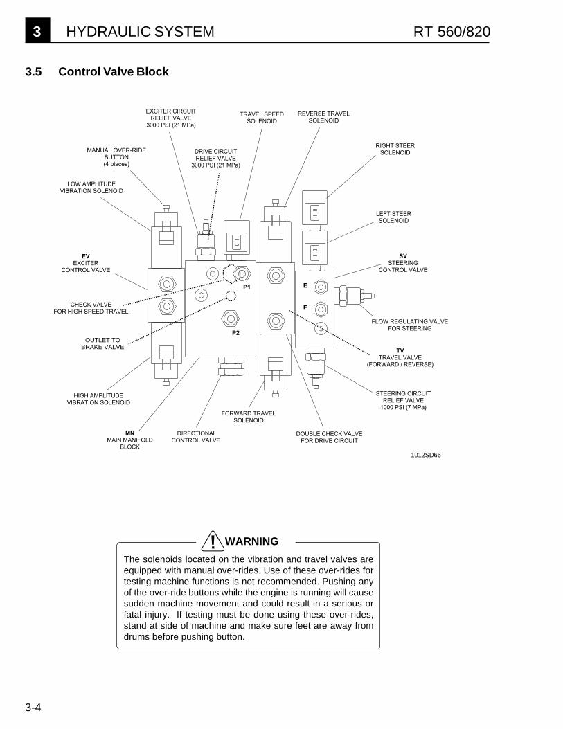
3.5 Control Valve Block
The solenoids located on the vibration and travel valves areequipped with manual over-rides. Use of these over-rides fortesting machine functions is not recommended. Pushing anyof the over-ride buttons while the engine is running will causesudden machine movement and could result in a serious orfatal injury. If testing must be done using these over-rides,stand at side of machine and make sure feet are away fromdrums before pushing button.
WARNING
1012SD66
HYDRAULIC SYSTEM 3RT 560/820
3-5
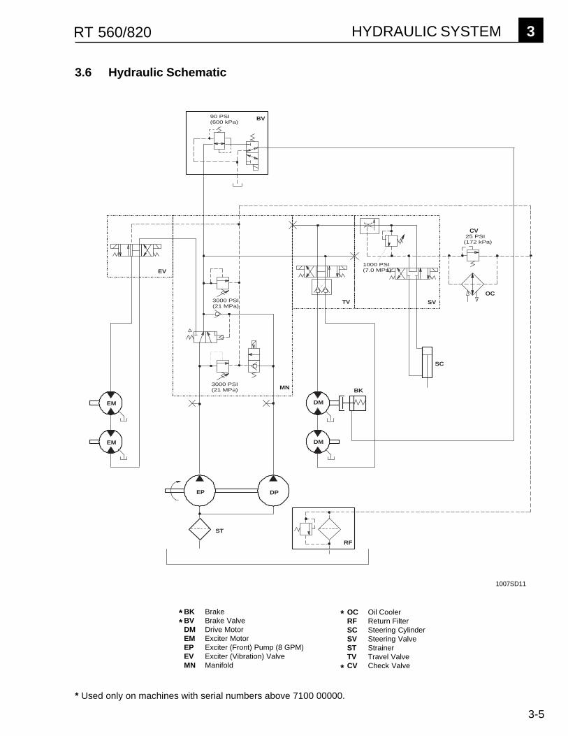
3.6 Hydraulic Schematic
EV
MN
TV SV
EP DP
3000 PSI(21 MPa)
3000 PSI(21 MPa)
1000 PSI (7.0 MPa)
SC
RF
ST
DM
DM
EM
EM
25 PSI(172 kPa)
BK
OC
BV90 PSI(600 kPa)
CV
1007SD11
* Used only on machines with serial numbers above 7100 00000.
OC Oil CoolerRF Return FilterSC Steering CylinderSV Steering ValveST StrainerTV Travel ValveCV Check Valve
BK BrakeBV Brake ValveDM Drive MotorEM Exciter MotorEP Exciter (Front) Pump (8 GPM)EV Exciter (Vibration) ValveMN Manifold
** *
*

3 HYDRAULIC SYSTEM RT 560/820
3-6
3.7 High Speed Travel Circuit
3000 PSI(21 MPa)
P1P2
3000 PSI(21 MPa)
RETURN LINETO HYDRAULIC TANK
TO STEERING VALVE
TO EXCITER(VIBRATION)
VALVE
HIGH PRESSURE FLOW
RETURN FLOW
PILOT PRESSURE
INACTIVE LINE (NO PRESSURE)
TO BRAKE VALVE
FROM EXCITERMOTOR
CASE DRAIN
b
j
a
d
e
fg
c
h
iSpring pressureshifts valve (h)and directs flowfrom front pump(g) into drivecircuit.
Valve (c) opensand directs flowfrom rear pump(f) into return line.
a TRAVEL VALVEb DOUBLE CHECK VALVEc TRAVEL SPEED VALVEd FRONT DRIVE MOTORe REAR DRIVE MOTORf REAR PUMPg FRONT PUMPh DIRECTIONAL CONTROL VALVEi CHECK VALVEj DRIVE CIRCUIT RELIEF VALVE
1012SD67
* Used only on machines with serial numbers above 7100 00000.
*
HYDRAULIC SYSTEM 3RT 560/820
3-7
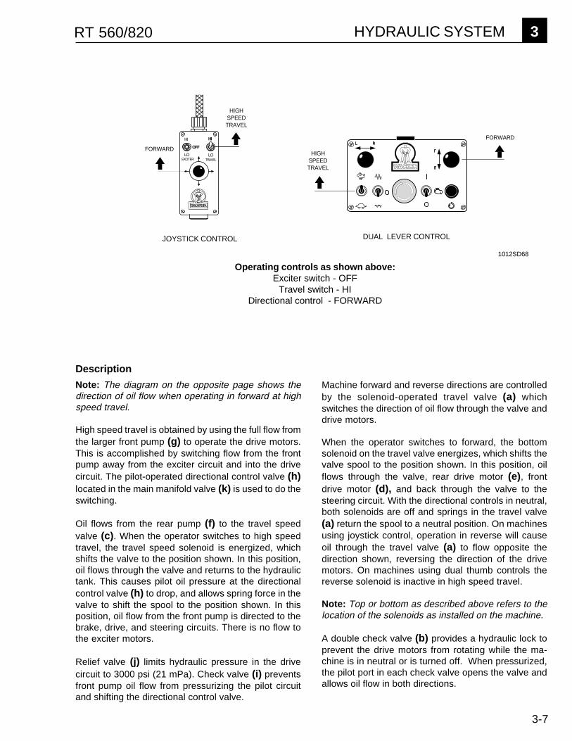
HIGH SPEEDTRAVEL
FORWARD
�������
��
���
������
��
�
FORWARD
HIGH SPEEDTRAVEL
JOYSTICK CONTROL
Operating controls as shown above:Exciter switch - OFF
Travel switch - HIDirectional control - FORWARD
DUAL LEVER CONTROL
1012SD68
Machine forward and reverse directions are controlledby the solenoid-operated travel valve (a) whichswitches the direction of oil flow through the valve anddrive motors.
When the operator switches to forward, the bottomsolenoid on the travel valve energizes, which shifts thevalve spool to the position shown. In this position, oilflows through the valve, rear drive motor (e), frontdrive motor (d), and back through the valve to thesteering circuit. With the directional controls in neutral,both solenoids are off and springs in the travel valve(a) return the spool to a neutral position. On machinesusing joystick control, operation in reverse will causeoil through the travel valve (a) to flow opposite thedirection shown, reversing the direction of the drivemotors. On machines using dual thumb controls thereverse solenoid is inactive in high speed travel.
Note: Top or bottom as described above refers to thelocation of the solenoids as installed on the machine.
A double check valve (b) provides a hydraulic lock toprevent the drive motors from rotating while the ma-chine is in neutral or is turned off. When pressurized,the pilot port in each check valve opens the valve andallows oil flow in both directions.
Description
Note: The diagram on the opposite page shows thedirection of oil flow when operating in forward at highspeed travel.
High speed travel is obtained by using the full flow fromthe larger front pump (g) to operate the drive motors.This is accomplished by switching flow from the frontpump away from the exciter circuit and into the drivecircuit. The pilot-operated directional control valve (h)located in the main manifold valve (k) is used to do theswitching.
Oil flows from the rear pump (f) to the travel speedvalve (c). When the operator switches to high speedtravel, the travel speed solenoid is energized, whichshifts the valve to the position shown. In this position,oil flows through the valve and returns to the hydraulictank. This causes pilot oil pressure at the directionalcontrol valve (h) to drop, and allows spring force in thevalve to shift the spool to the position shown. In thisposition, oil flow from the front pump is directed to thebrake, drive, and steering circuits. There is no flow tothe exciter motors.
Relief valve (j) limits hydraulic pressure in the drivecircuit to 3000 psi (21 mPa). Check valve (i) preventsfront pump oil flow from pressurizing the pilot circuitand shifting the directional control valve.
3 HYDRAULIC SYSTEM RT 560/820
3-8
3000 PSI(21 MPa)
P1P2
3000 PSI(21 MPa)
TO EXCITER(VIBRATION)
VALVE
HIGH PRESSURE FLOW
RETURN FLOW
PILOT PRESSURE
INACTIVE LINE (NO PRESSURE)
TO BRAKE VALVE
Pilot pressure
RETURN LINETO HYDRAULIC TANK
TO STEERING VALVE
FROM HYDRAULIC
TANK
FROM EXCITERMOTOR CASE
DRAIN
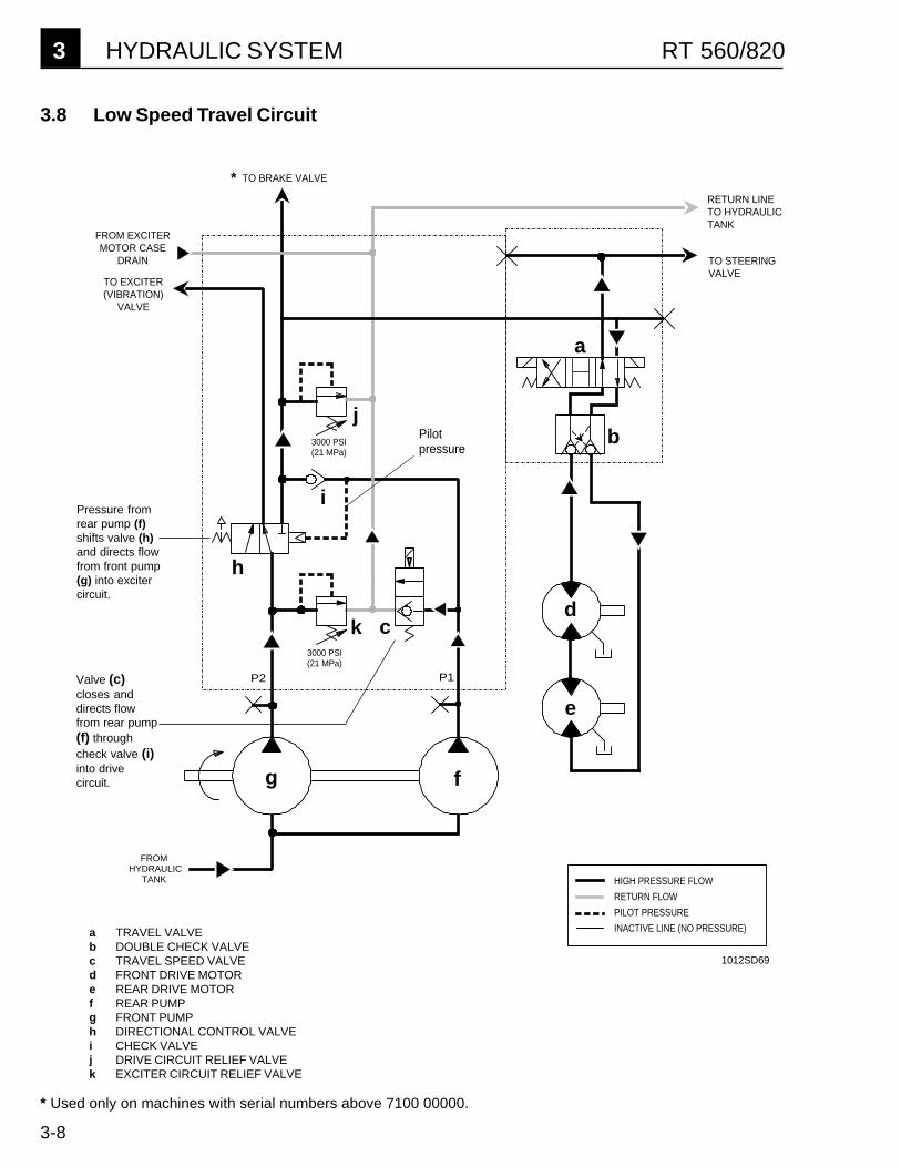
3.8 Low Speed Travel Circuit
a
b
cd
e
fg
h
i
k
j
Pressure fromrear pump (f)shifts valve (h)and directs flowfrom front pump(g) into excitercircuit.
Valve (c)closes anddirects flowfrom rear pump(f) throughcheck valve (i)into drivecircuit.
1012SD69
a TRAVEL VALVEb DOUBLE CHECK VALVEc TRAVEL SPEED VALVEd FRONT DRIVE MOTORe REAR DRIVE MOTORf REAR PUMPg FRONT PUMPh DIRECTIONAL CONTROL VALVEi CHECK VALVEj DRIVE CIRCUIT RELIEF VALVEk EXCITER CIRCUIT RELIEF VALVE
* Used only on machines with serial numbers above 7100 00000.
*
HYDRAULIC SYSTEM 3RT 560/820
3-9
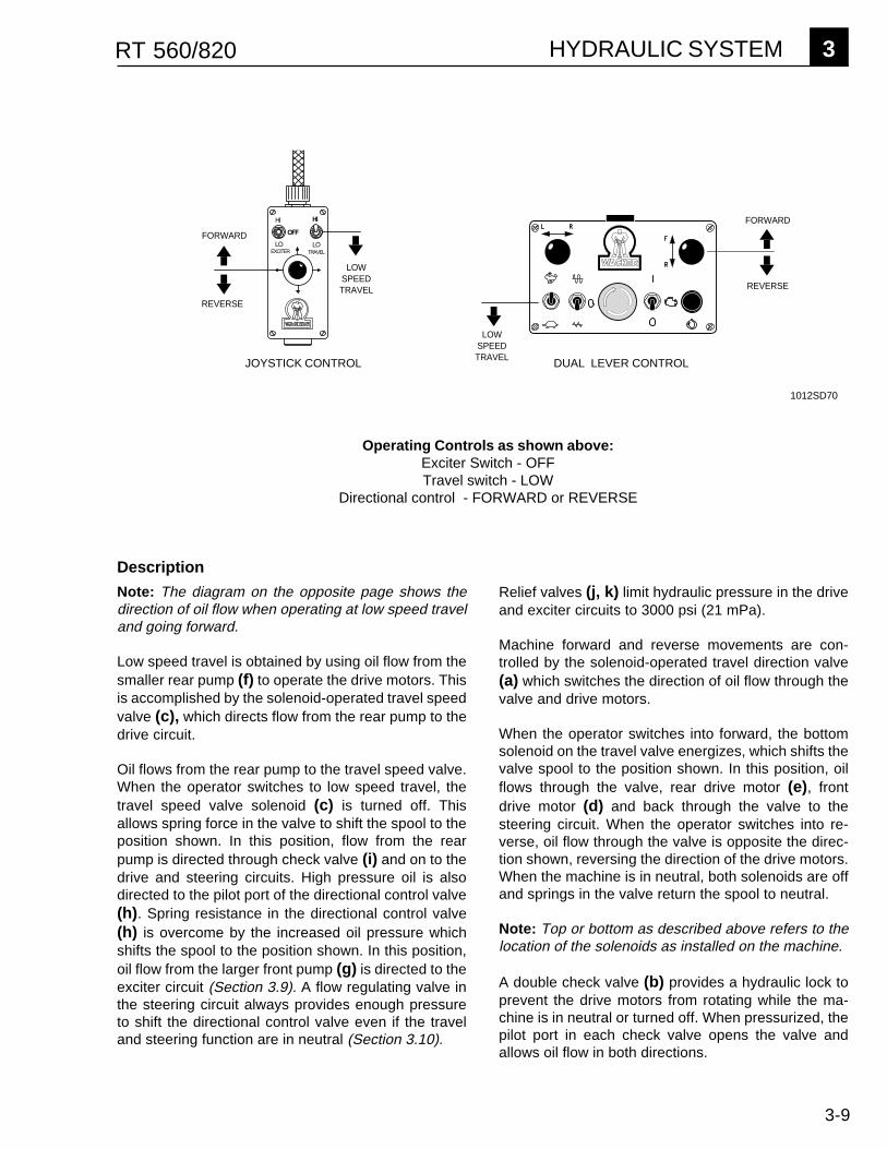
Operating Controls as shown above:Exciter Switch - OFFTravel switch - LOW
Directional control - FORWARD or REVERSE
�������
��
���
������
��
�FORWARD
LOWSPEEDTRAVEL
LOW SPEEDTRAVEL
FORWARD
REVERSE
REVERSE
JOYSTICK CONTROL DUAL LEVER CONTROL
1012SD70
Relief valves (j, k) limit hydraulic pressure in the driveand exciter circuits to 3000 psi (21 mPa).
Machine forward and reverse movements are con-trolled by the solenoid-operated travel direction valve(a) which switches the direction of oil flow through thevalve and drive motors.
When the operator switches into forward, the bottomsolenoid on the travel valve energizes, which shifts thevalve spool to the position shown. In this position, oilflows through the valve, rear drive motor (e), frontdrive motor (d) and back through the valve to thesteering circuit. When the operator switches into re-verse, oil flow through the valve is opposite the direc-tion shown, reversing the direction of the drive motors.When the machine is in neutral, both solenoids are offand springs in the valve return the spool to neutral.
Note: Top or bottom as described above refers to thelocation of the solenoids as installed on the machine.
A double check valve (b) provides a hydraulic lock toprevent the drive motors from rotating while the ma-chine is in neutral or turned off. When pressurized, thepilot port in each check valve opens the valve andallows oil flow in both directions.
Description
Note: The diagram on the opposite page shows thedirection of oil flow when operating at low speed traveland going forward.
Low speed travel is obtained by using oil flow from thesmaller rear pump (f) to operate the drive motors. Thisis accomplished by the solenoid-operated travel speedvalve (c), which directs flow from the rear pump to thedrive circuit.
Oil flows from the rear pump to the travel speed valve.When the operator switches to low speed travel, thetravel speed valve solenoid (c) is turned off. Thisallows spring force in the valve to shift the spool to theposition shown. In this position, flow from the rearpump is directed through check valve (i) and on to thedrive and steering circuits. High pressure oil is alsodirected to the pilot port of the directional control valve(h). Spring resistance in the directional control valve(h) is overcome by the increased oil pressure whichshifts the spool to the position shown. In this position,oil flow from the larger front pump (g) is directed to theexciter circuit (Section 3.9). A flow regulating valve inthe steering circuit always provides enough pressureto shift the directional control valve even if the traveland steering function are in neutral (Section 3.10).
3 HYDRAULIC SYSTEM RT 560/820
3-10
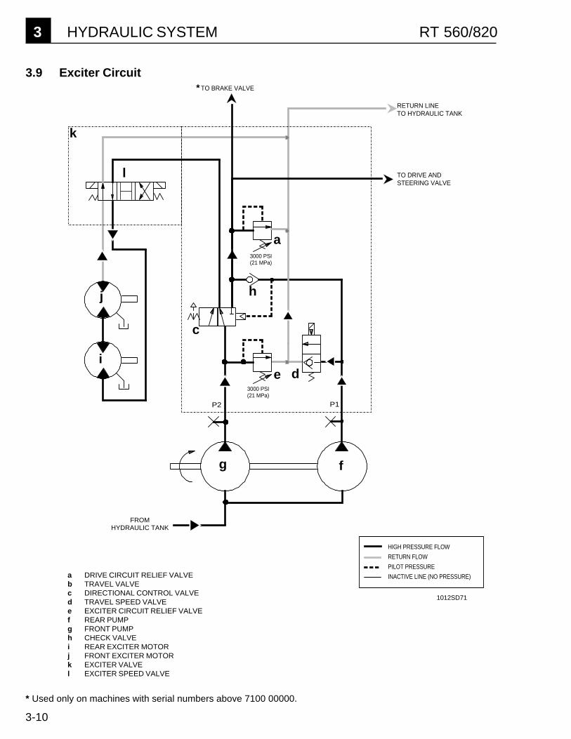
3.9 Exciter Circuit
* Used only on machines with serial numbers above 7100 00000.
a DRIVE CIRCUIT RELIEF VALVEb TRAVEL VALVEc DIRECTIONAL CONTROL VALVEd TRAVEL SPEED VALVEe EXCITER CIRCUIT RELIEF VALVEf REAR PUMPg FRONT PUMPh CHECK VALVEi REAR EXCITER MOTORj FRONT EXCITER MOTORk EXCITER VALVEl EXCITER SPEED VALVE
*
1012SD71
a
c
de
fg
i
j
k
l
h
HIGH PRESSURE FLOW
RETURN FLOW
PILOT PRESSURE
INACTIVE LINE (NO PRESSURE)
3000 PSI(21 MPa)
P1P2
3000 PSI(21 MPa)
RETURN LINETO HYDRAULIC TANK
TO DRIVE ANDSTEERING VALVE
TO BRAKE VALVE
FROM HYDRAULIC TANK
HYDRAULIC SYSTEM 3RT 560/820
3-11
JOYSTICK CONTROL DUAL LEVER CONTROL
EXCITER
HI
OFF
LOTRAVEL
HI
LO
LOWSPEEDTRAVEL
LOW SPEEDTRAVEL
VIBRATION HI
VIBRATION LO
VIBRATION HI
VIBRATION LO
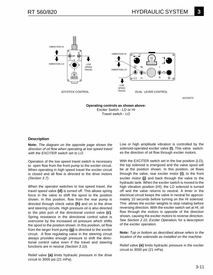
Operating controls as shown above:Exciter Switch - LO or HI
Travel switch - LO
1012SD72
Description
Note: The diagram on the opposite page shows thedirection of oil flow when operating at low speed travelwith the EXCITER switch set to LO.
Operation of the low speed travel switch is necessaryto open flow from the front pump to the exciter circuit.When operating in high speed travel the exciter circuitis closed and all flow is directed to the drive motors(Section 3.7).
When the operator switches to low speed travel, thetravel speed valve (d) is turned off. This allows springforce in the valve to shift the spool to the positionshown. In this position, flow from the rear pump isdirected through check valve (h) and on to the driveand steering circuits. High pressure oil is also directedto the pilot port of the directional control valve (c).Spring resistance in the directional control valve isovercome by the increased oil pressure which shiftsthe spool to the position shown. In this position, oil flowfrom the larger front pump (g) is directed to the excitercircuit. A flow regulating valve in the steering circuitalways provides enough pressure to shift the direc-tional control valve even if the travel and steeringfunctions are in neutral (Section 3.10).
Relief valve (a) limits hydraulic pressure in the drivecircuit to 3000 psi (21 mPa).
Low or high amplitude vibration is controlled by thesolenoid-operated exciter valve (l). This valve switch-es the direction of oil flow through exciter motors.
With the EXCITER switch set in the low position (LO),the top solenoid is energized and the valve spool willbe at the position shown. In this position, oil flowsthrough the valve, rear exciter motor (i), to the frontexciter motor (j) and back through the valve to thehydraulic tank. When the exciter switch is moved to thehigh vibration position (HI), the LO solenoid is turnedoff and the valve returns to neutral. A timer in theelectrical circuit keeps the valve in neutral for approxi-mately 10 seconds before turning on the HI solenoid.This allows the exciter weights to stop rotating beforereversing direction. With the exciter switch set at HI, oilflow through the motors is opposite of the directionshown, causing the exciter motors to reverse direction.See Section 2.10, Exciter Operation, for a descriptionof the exciter operation.
Note: Top or bottom as described above refers to thelocation of the solenoids as installed on the machine.
Relief valve (e) limits hydraulic pressure in the excitercircuit to 3000 psi (21 mPa).

3 HYDRAULIC SYSTEM RT 560/820
3-12
3.10 Steering Circuit
T
E F
FROM MAIN MANIFOLD
TO HYDRAULIC TANK
1000 PSI(7 MPa)
HIGH PRESSURE FLOW
RETURN FLOW
PILOT PRESSURE
INACTIVE LINE (NO PRESSURE)
a TRAVEL VALVEb DOUBLE CHECK VALVEc FLOW REGULATING VALVEd FRONT DRIVE MOTORe REAR DRIVE MOTORf STEERING CIRCUIT RELIEF VALVEg STEERING CONTROL VALVEh STEERING CYLINDER
fa
b
c
g
h
1012SD73
d
e

HYDRAULIC SYSTEM 3RT 560/820
3-13
EXCITER
HI
LOTRAVEL
HI
LO
STEERLEFT
STEERRIGHT
STEERLEFT
STEERRIGHT
OFF
JOYSTICK CONTROL DUAL LEVER CONTROL
Operating controls as shown above:Directional control - LEFT or RIGHT
When the operator steers left, the top solenoid on thesteering valve (g) is energized and the valve spoolshifts to the position shown. In this position, oil flowsout port "E" of the valve, to the rod end of the steeringcylinder (h). At the same time, oil from the head end ofthe cylinder returns through port "F" and back to thehydraulic tank. This causes the cylinder rod to retract,turning the machine left. When the operator steersright, oil flows in the opposite direction causing thecylinder rod to extend and turn the machine to theright. With steering in neutral, both solenoids areturned off. Springs in the valve return the spool tocenter which allows oil to pass through the valve, outport "T", and back to tank.
Note: Top or bottom as described above refers to thelocation of the solenoids as installed on the machine.
Relief valve (e) limits hydraulic pressure in the steeringcircuit to 1000 psi (7 mPa).
1012SD74
Description
Note: The diagram on the opposite page shows thedirection of oil flow when steering left.
The steering circuit consists of a flow regulating valve(c), pressure relief valve (f), solenoid-operated controlvalve (g), and steering cylinder (h).
Return oil from the drive circuit flows into the steeringcircuit and through the flow regulating valve (c) beforeentering the solenoid-operated steering control valve(g). The flow regulating valve maintains a constant 1gpm flow rate in the steering circuit. This is necessaryto provide the same degree of steering control whetheroperating in low or high speed travel. It also createssufficient back pressure in the system to shift thedirectional control valve in the main manifold. Thiskeeps the exciter circuit open when the steering andtravel valves are in neutral.
3 HYDRAULIC SYSTEM RT 560/820
3-14
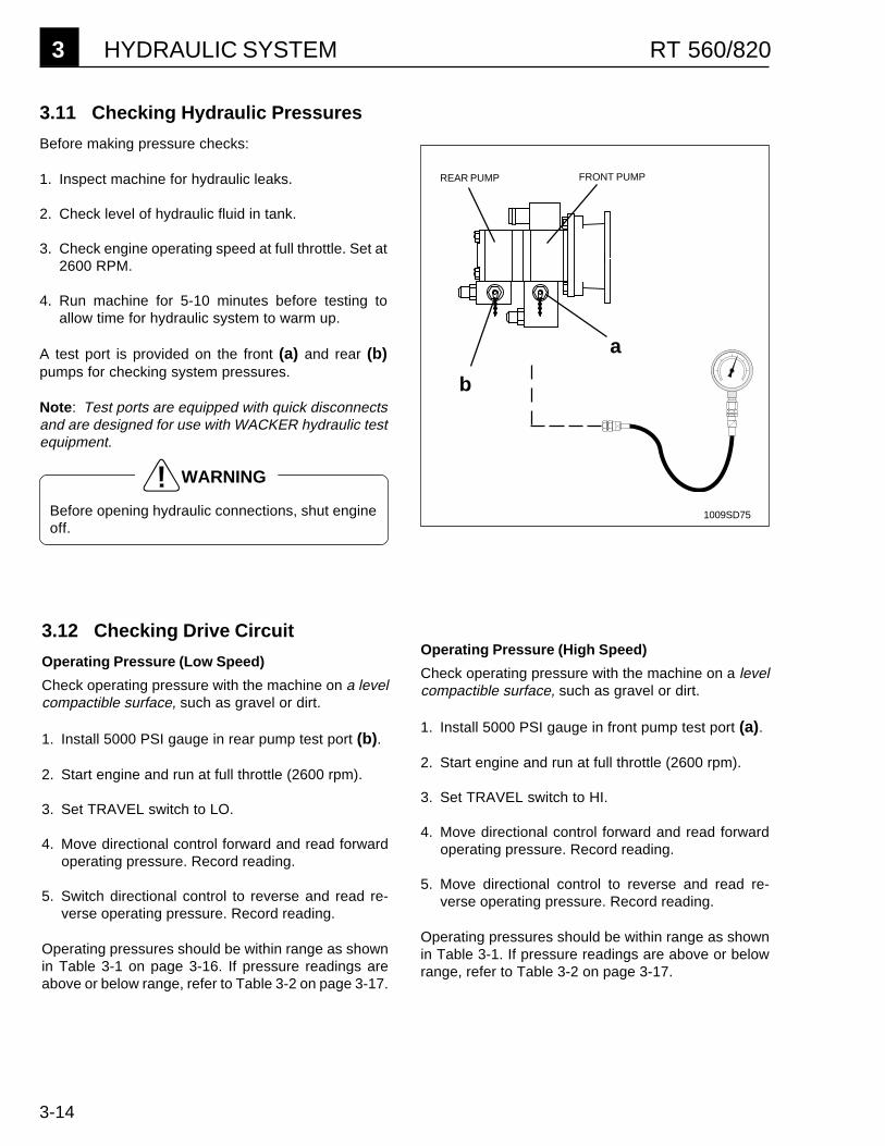
3.11 Checking Hydraulic Pressures
Before making pressure checks:
1. Inspect machine for hydraulic leaks.
2. Check level of hydraulic fluid in tank.
3. Check engine operating speed at full throttle. Set at2600 RPM.
4. Run machine for 5-10 minutes before testing toallow time for hydraulic system to warm up.
A test port is provided on the front (a) and rear (b)pumps for checking system pressures.
Note: Test ports are equipped with quick disconnectsand are designed for use with WACKER hydraulic testequipment.
1009SD75
b
a
REAR PUMP FRONT PUMP
Before opening hydraulic connections, shut engineoff.
WARNING
Operating Pressure (High Speed)
Check operating pressure with the machine on a levelcompactible surface, such as gravel or dirt.
1. Install 5000 PSI gauge in front pump test port (a).
2. Start engine and run at full throttle (2600 rpm).
3. Set TRAVEL switch to HI.
4. Move directional control forward and read forwardoperating pressure. Record reading.
5. Move directional control to reverse and read re-verse operating pressure. Record reading.
Operating pressures should be within range as shownin Table 3-1. If pressure readings are above or belowrange, refer to Table 3-2 on page 3-17.
3.12 Checking Drive Circuit
Operating Pressure (Low Speed)
Check operating pressure with the machine on a levelcompactible surface, such as gravel or dirt.
1. Install 5000 PSI gauge in rear pump test port (b).
2. Start engine and run at full throttle (2600 rpm).
3. Set TRAVEL switch to LO.
4. Move directional control forward and read forwardoperating pressure. Record reading.
5. Switch directional control to reverse and read re-verse operating pressure. Record reading.
Operating pressures should be within range as shownin Table 3-1 on page 3-16. If pressure readings areabove or below range, refer to Table 3-2 on page 3-17.
HYDRAULIC SYSTEM 3RT 560/820
3-15
Checking Drive Circuit, cont'd
Relief Pressure
1. Block in front of and behind both drums to preventmachine from moving, or deadhead machineagainst a solid concrete abutment.
2. Install a 5000 PSI gauge in front pump test port (a).
3. Set TRAVEL switch to HI.
4. Start engine and run machine at full throttle. Pushdirectional control forward until pressure on gaugetops out. This is the high speed relief valve pres-sure. Make sure drums do not spin. Record reading.
5. Stop engine. Set TRAVEL switch to LO.
6. Install gauge in rear pump test port (b) and repeatstep 4. This is the low speed relief valve pressure.Record reading.
Relief valve pressures should be within range asshown in Table 3-1. If pressure readings are above orbelow range, refer to Table 3-2 on page 3-17.
3.13 Checking Vibration Circuit
Test vibration with drums on soil or gravel. If testing isdone inside, position drum on rubber tire or heavy matto absorb vibration. Do not run vibration on concrete.
Operating Pressure (High Amplitude)
1. Install 5000 PSI gauge in front pump test port (a).
2. Start engine and run machine at full throttle (2600rpm) with directional controls in neutral andTRAVEL switch in LO.
3. Switch vibration to HI. Gauge will show relief pres-sure momentarily as exciter starts and then fall tonormal operating pressure as exciter reaches fullspeed. Record reading.
Operating pressures should be within range as shownin Table 3-1. If pressure readings are above or belowrange, refer to Table 3-2 on page 3-17.
Operating Pressure (Low Amplitude)
1. Install 5000 PSI gauge in front pump test port (a).
2. Start engine and run machine at full throttle (2600rpm) with directional control in neutral and TRAVELswitch in LO.
3. Switch vibration to LO. Gauge will show relief pres-sure momentarily as exciter starts and then fall tonormal operating pressure as exciter reaches fullspeed. Record reading.
Operating pressures should be within range as shownin Table 3-1. If pressure readings are above or belowrange, refer to Table 3-2 on page 3-17.
WARNING
Make sure blocks are large enough so machinewill not climb over them during testing.

3 HYDRAULIC SYSTEM RT 560/820
3-16
3.14 Checking Steering Circuit
1. Install 2000 PSI gauge in rear pump test port (b).
2. Start engine and run machine at full throttle (2600rpm).
3. Set travel speed to LO.Note: Running in high speed travel will cause thesteering circuit to run off the front pump.
4. Move directional control right or left. Gauge willshow operating pressure until cylinder gets to endof stroke and then show relief pressure. Recordreadings.
Operating and relief pressures should be within rangeas shown in Table 3-1. If pressure readings are aboveor below range, refer to Table 3-2 on page 3-17.
3.16 System pressures
Table 3-1 below lists normal operating pressures based on the machine running over a level compactible surface.These pressures are approximate and will vary for different operating conditions. Operating pressure readings forthe drive and steering circuits may be higher when operating in extremely loose soils or on an incline. Operatingpressure readings will be lower when operating on flat, hard surfaces where there is less surface resistance.
Table 3-1. Hydraulic System Pressures
Normal Operating Relief Valve TestPressure @ 2600 RPM Pressure Port
PSI (mPa) PSI (mPa) Location
Forward or 180 - 600 (1.2 - 4.2) 3000 (21) Rear PumpReverse inLOW Speed
Forward or 300 - 800 (2.1 - 5.6) 3000 (21) Front PumpReverse inHIGH Speed
Exciter in 1050 - 1250 (7.3 - 8.7) 3000 (21) Front PumpLOW Vibration
Exciter in 1200 - 1600 (8.4 - 11.2) 3000 (21) Front PumpHIGH Vibration
Steering 300 - 800 (2.1 - 5.6) 1000 (7) Rear Pump(Low speed travel)
3.15 Testing Drive & ExciterCircuit Relief Valves
Drive and exciter circuit relief valves are identical andset at the same pressures. They can be tested forcorrect operation by simply swapping positions withone another. Swap the one in question with the otherand test for correct pressure (see table 3-1). If pres-sure is correct with the second valve installed, theoriginal valve is malfunctioning and will require re-placement.

HYDRAULIC SYSTEM 3RT 560/820
3-17
Table 3-2. Hydraulic System Troubleshooting
Problem Possible Cause Remedy
Drive Circuit Operating Pressuresare too Low (Below 180 psi)
Testing surface is too hard orsmooth.
Engine operating below 2600 rpm.
Suction hose or fittings leaking,allowing air into pump inlet.
Oil level is too low in tank.
Worn pump or pump coupling.
Malfunctioning relief valve.
Check readings while machine is oncompactible soil. If pressurereadings still are low, continue.
Set throttle to deliver 2600 rpm.
Tighten hose fittings as necessary.
Make sure oil is at proper level.
Remove pump and coupling andrepair as necessary.
Test relief valve for proper operation(see Section 3.15).
Drive Circuit Operating Pressuresare too High (Above 800 psi)
Wrong weight oil in drive gearcase(viscosity too high).
Engine operating above 2600 rpm.
Drum binding due to dirt build-upbetween drums and drum supports.
Drive assembly binding due to wornor improperly assembled parts.
Hoses routed incorrectly.
Drain and fill with proper weight oilfor operating conditions. If pressurereadings still are high, continue.
Set throttle to deliver 2600 rpm.
Remove dirt build-up.
Remove, inspect, repair andproperly assemble drive assembly.
Make sure hoses are routedproperly. See Hydraulic FlowDiagram on page 3-2.
Exciter Circuit OperatingPressure is too Low (Below 800psi) - Drive Circuit PressuresOkay
Sticky spool in exciter or directionalcontrol valve, allowing partialpressure loss.
Hoses leaking.
Worn exciter motor(s).
Malfunctioning relief valve.
Check electrical circuits to makesure solenoids are functioningproperly. If okay, continue.
Remove control valve and repair orreplace as necessary.
Tighten fittings.
Repair exciter motor(s).
Test relief valve for proper operation(see Section 3.15).
Exciter Circuit OperatingPressure is too High (Above 1800psi) - Drive Circuit PressuresOkay
Wrong weight oil in exciterassembly (viscosity too high).
Exciter assembly oil level too high.
Binding in exciter assembly(bearings worn or damaged).
Drain and fill with proper weight oilfor operating conditions.
Remove, inspect and repair exciterassembly, as necessary. Fill with oilto proper level.
Remove, inspect and repair exciterassembly, as necessary.
Relief Pressure too Low Relief valve adjustment wrong.
Worn pump or motor.
Adjust or replace valve asnecessary.
Repair as necessary.

3 HYDRAULIC SYSTEM RT 560/820
3-18
TA
NK
H1
H2
H3
H4
H3
H4
H5
H6
H7
H8
H9
H1
H10
H4
H9
SE
E R
IGH
T S
IDE
VIE
W F
OR
H3,
H8,
& H
10
RE
AR
DR
UM
LE
FT
SID
E V
IEW
H7
H1
SE
E R
IGH
T S
IDE
VIE
W F
OR
H2,
H5,
& H
9 H2
H2
H5
TO
TA
NK
SE
E V
IEW
"A
"
H11 FR
ON
T D
RU
M
SE
E V
IEW
"A
" -
TA
NK
F
OR
H1
& H
2
HO
SE
R
OU
TIN
G
H1
F
RO
M F
RO
NT
DR
UM
DR
IVE
MO
TO
R C
AS
E D
RA
IN T
O T
AN
KH
2
FR
OM
FR
ON
T D
RU
M E
XC
ITE
R D
RIV
E M
OT
OR
CA
SE
DR
AIN
TO
TA
NK
H3
F
RO
M R
EA
R D
RU
M D
RIV
E M
OT
OR
CA
SE
DR
AIN
TO
TA
NK
H4
F
RO
M R
EA
R D
RU
M E
XC
ITE
R D
RIV
E M
OT
OR
CA
SE
DR
AIN
TO
TA
NK
H5
F
RO
M M
AN
IFO
LD L
OW
VIB
RA
TIO
N P
OR
T (
A)
TO
FR
ON
T D
RU
M E
XC
ITE
R D
RIV
E M
OT
OR
H6
F
RO
M M
AN
IFO
LD R
EV
ER
SE
TR
AV
EL
PO
RT
TO
FR
ON
T D
RU
M D
RIV
E M
OT
OR
H7
F
RO
M M
AN
IFO
LD H
IGH
VIB
RA
TIO
N P
OR
T (
B)
TO
RE
AR
DR
UM
EX
CIT
ER
MO
TO
RH
8
FR
OM
MA
NIF
OLD
FO
RW
AR
D T
RA
VE
L P
OR
T T
O R
EA
R D
RU
M D
RIV
E M
OT
OR
H9
F
RO
M F
RO
NT
DR
UM
EX
CIT
ER
MO
TO
R T
O R
EA
R D
RU
M E
XC
ITE
R M
OT
OR
H10
FR
OM
FR
ON
T D
RU
M D
RIV
E M
OT
OR
TO
RE
AR
DR
UM
DR
IVE
MO
TO
RH
11 F
RO
M B
RA
KE
TO
FIT
TIN
G IN
FR
ON
T D
RU
M S
UP
PO
RT
TO
BR
AK
E V
ALV
E IN
RE
AR
OF
MA
CH
INE
VIE
W "
A"
- T
AN
K
3.17 Hydraulic Hose Routing and Location
1014SD10

HYDRAULIC SYSTEM 3RT 560/820
3-19
1014SD11
RE
AR
DR
UM
FR
ON
T D
RU
M
TO
TA
NK
S
EE
VIE
W "
A"
- T
AN
KLE
FT
SID
E V
IEW
TO
TA
NK
S
EE
VIE
W "
A"
- T
AN
KLE
FT
SID
E V
IEW
SE
E L
EF
T S
IDE
VIE
WF
OR
H4,
H7,
& H
9S
EE
LE
FT
SID
E V
IEW
FO
R H
1, H
6, H
10
RIG
HT
SID
E V
IEWH1
H2
H3
H4
H5
H6
H7
H8
H9
H10
H2
H5
H4

3 HYDRAULIC SYSTEM RT 560/820
3-20
NOTES
4-1
DRUM 4RT 560/820
UNIT 4
DRUM
4.1 Introduction ............................................................................................ 4-14.2 Changing Oil .......................................................................................... 4-14.3 Drum Assembly - Exploded View .......................................................... 4-24.4 Drums .................................................................................................... 4-34.5 Drum Support Cover .............................................................................. 4-44.6 Drive Bearings & Seals ......................................................................... 4-54.7 Drivecase .............................................................................................. 4-64.8 Drivecase - Exploded View.................................................................... 4-74.9 Brake (S/N 7100 00000 & Above) ......................................................... 4-84.10 Servicing Brake ..................................................................................... 4-94.11 Drive Motor .......................................................................................... 4-104.12 Drivecase Components ....................................................................... 4-11
4.1 Introduction
This section covers complete disassembly and assembly of the front and rear drum support assemblies includingreplacement of bearings, seals, and drive motor.
Note: On machines with serial numbers 7100 00000 & above, the front drum also includes a brake assembly.
4.2 Changing Oil
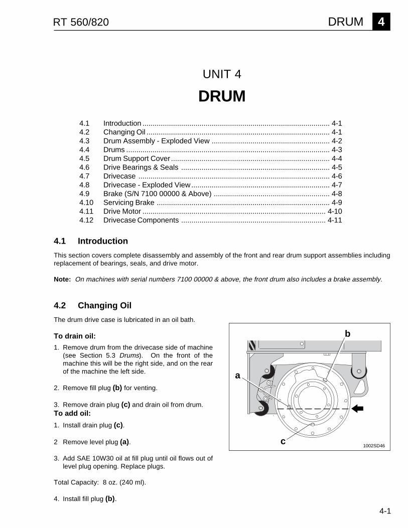
The drum drive case is lubricated in an oil bath.
To drain oil:
1. Remove drum from the drivecase side of machine(see Section 5.3 Drums). On the front of themachine this will be the right side, and on the rearof the machine the left side.
2. Remove fill plug (b) for venting.
3. Remove drain plug (c) and drain oil from drum.To add oil:
1. Install drain plug (c).
2 Remove level plug (a).
3. Add SAE 10W30 oil at fill plug until oil flows out oflevel plug opening. Replace plugs.
Total Capacity: 8 oz. (240 ml).
4. Install fill plug (b).
b
a
c1002SD46
4-2
4 DRUM RT 560/820
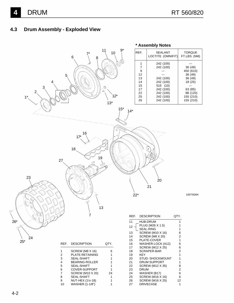
4.3 Drum Assembly - Exploded View
REF. DESCRIPTION QTY.
1 SCREW (M8 X 16) 62 PLATE-RETAINING 13 SEAL-SHAFT 14 BEARING-ROLLER 15 SEAL-SHAFT 16 COVER-SUPPORT 17 SCREW (M10 X 20) 248 SEAL-SHAFT 19 NUT-HEX (1¼-18) 110 WASHER (1-1/8") 1
1007SD64
20
2425*
23
27
18
1617*
14*
21
22*
23
1*
5
67*
8
1110
9*
13*
12*
15*
26*
7
13
19
4
11 HUB-DRUM 1PLUG (M26 X 1.5) 1SEAL-RING 1
13 SCREW (M10 X 16) 614 SCREW (M8 X 20) 215 PLATE-COVER 116 WASHER-LOCK (A12) 617 SCREW (M12 X 25) 618 SCRAPER-BAR 219 KEY 120 STUD- SHOCKMOUNT 121 DRUM SUPPORT 122 SCREW (M12 X 35) 823 DRUM 224 WASHER (B17) 625 SCREW (M16 X 16) 626 SCREW (M16 X 25) 1227 DRIVECASE 1
REF. DESCRIPTION QTY.
12
* Assembly Notes
REF. SEALANT TORQUELOCTITE (OMNIFIT) FT.LBS. (NM)
1 242 (100) ---7 242 (100) 36 (49)
9 --- 450 (610)12 --- 36 (49)13 242 (100) 36 (49)14 242 (100) 18 (25)15 515 (10) ---17 242 (100) 63 (85)22 242 (100) 88 (120)25 242 (100) 155 (210)26 242 (100) 155 (210)

4-3
DRUM 4RT 560/820
4.4 Drums
Removal:
1. Lock articulated joint (Section 1.5).
2. Lift machine by the lifting eye (a) using an appro-priate crane or hoist. Also use jack stands tosupport machine from underneath (b) machineframe.
3. Loosen the three M12 screws (17) and removescraper bar (18).
4. Remove the six M16 (26) screws holding the drum(23) to the drivecase.
5. Remove the three M16 (25) screws and insertthree M16 x 55 screws into the holes. Turn screwsin to push drum off hub.
Installation:
1. Install drum (23) to drivecase (27) with M12screws (26). Use Loctite 242, or an equivalentthreadlocking compound, on screws, and torqueto 155 ft.lbs. (210 Nm).
2. Install the three M16 x 16 screws (25) and wash-ers (24) into pusher holes to plug holes and pro-tect threads. Secure screws with Loctite 242, orequivalent.
3. Install scraper bar. Secure screws with Loctite242, or equivalent, and torque to 63 ft. lbs. (85Nm).
Recommended Tools
Socket - 1-7/8", 19 mm, 24 mmAllen Wrench - 6 mm, 8 mm, 10 mm, 14 mmOpen End Wrench - 19 mmTorque WrenchLoctite 242, 545 (or Equivalents)Three M16 x 55 ScrewsThree M10 x 55 ScrewsThree M12 x 90 Hardened Screws (P/N 11411)SiliconeArbor PressPropane TorchGrease - Shell Alvania No. 2
25
FIG. 4-2 REMOVING DRUMS
a
26
b
17
18
231012SD75

4-4
4 DRUM RT 560/820
4.5 Drum Support Cover
See Section 4.3 for Drum Assembly Drawing
Removal:
1. Remove drums and scrapers bars (Section 4.4).
2. Using a large breaker bar remove the 1-1/4" hexnut (9) and washer (10) which holds the drum onthe axle.
3. Insert three M16 x 55 screws into alternatingholes on hub in which drum was mounted. Turnscrews (c) in to push drum hub (11) off supportcover (6).
4. Remove wiper seal (8) from support cover (6).
5. Remove the twelve M10 screws (7) holding thesupport cover (6) to the drum support (21).
6. Remove the three M10 (13) screws in the supportcover. Into these holes insert three M10 x 55screws. Turn screws in to push cover from drum
6
7
13
c
8
9
10
11
450 ft.lbs.(610 Nm)
FIG. 4-3 SUPPORT COVER CROSS-SECTION
1012SD76
support.
Installation:
Drum drivecase must be in place before assemblingdrum support cover (Section 4.7).
1. Install support cover on drum support using twelveM10 screws (7). Secure screws using Loctite 242and torque to 36 ft. lbs. (49 Nm). Install the threeM10 screws (13) back into pusher holes to protectthe threads.
2. Apply a bead of silicone to cover in area (d) wherewiper seal (8) will seat. This will help hold seal inplace and prevent it from spinning. Attach seal tosupport cover.
3. Install drum hub into drum support assembly andsecure with washer (10) and nut (9). Use Loctite242 on axle shaft threads and torque nut to 450 ft.lbs. (610 Nm).
4. Install drums and scraper bars.
d
4-5
DRUM 4RT 560/820
1
2
3
4a
5
11
4b
4.6 Drive Bearings & Seals
Disassembly:
1. Remove drum support cover (Section 4.5).
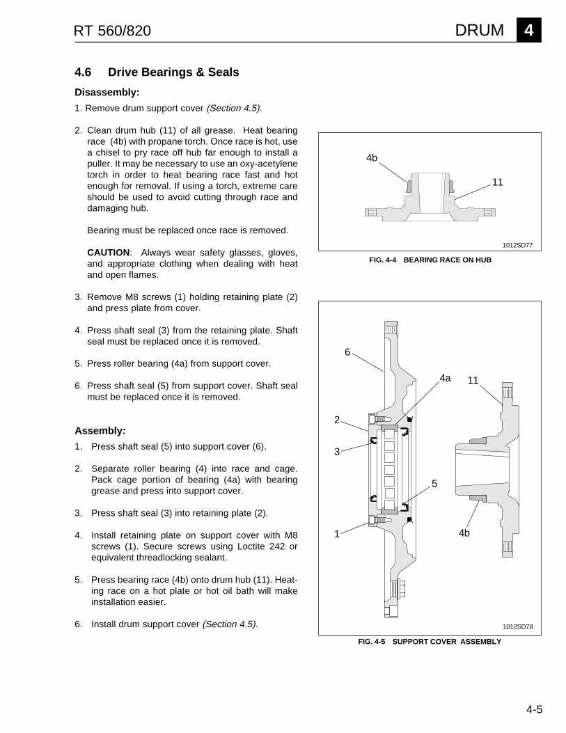
2. Clean drum hub (11) of all grease. Heat bearingrace (4b) with propane torch. Once race is hot, usea chisel to pry race off hub far enough to install apuller. It may be necessary to use an oxy-acetylenetorch in order to heat bearing race fast and hotenough for removal. If using a torch, extreme careshould be used to avoid cutting through race anddamaging hub.
Bearing must be replaced once race is removed.
CAUTION: Always wear safety glasses, gloves,and appropriate clothing when dealing with heatand open flames.
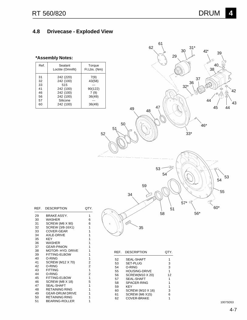
3. Remove M8 screws (1) holding retaining plate (2)and press plate from cover.
4. Press shaft seal (3) from the retaining plate. Shaftseal must be replaced once it is removed.
5. Press roller bearing (4a) from support cover.
6. Press shaft seal (5) from support cover. Shaft sealmust be replaced once it is removed.
Assembly:
1. Press shaft seal (5) into support cover (6).
2. Separate roller bearing (4) into race and cage.Pack cage portion of bearing (4a) with bearinggrease and press into support cover.
3. Press shaft seal (3) into retaining plate (2).
4. Install retaining plate on support cover with M8screws (1). Secure screws using Loctite 242 orequivalent threadlocking sealant.
5. Press bearing race (4b) onto drum hub (11). Heat-ing race on a hot plate or hot oil bath will makeinstallation easier.
6. Install drum support cover (Section 4.5).
4b
FIG. 4-5 SUPPORT COVER ASSEMBLY
11
FIG. 4-4 BEARING RACE ON HUB
6
1012SD77
1012SD78

4-6
4 DRUM RT 560/820
4.7 Drivecase
See Section 4.3 for Drum Assembly Drawing
Removal:
1. Remove drums and scrapers bars (Section 4.4).
2. Remove support cover (Section 4.5).
3. Disconnect hydraulic hoses from drive motor. Ma-chines with S/N 7100 00000 & above include abrake assembly on the front drum. On these ma-chines it will also be necessary to disconnect thehydraulic line that engages the brake.
4. Remove the twelve M10 screws (7) holding thedrivecase (27) to the drum support (21).
5. Note: Before removing the drivecase, add refer-ence marks to the drum support and the drivecase.This will help align the two pieces later on andmake installation easier.
Remove the three M10 screw plugs (13) in thedrive assembly flange and insert three M10 x 55screws (a) in their place. Turn screws in to pushdrivecase from drum support. Pull completedrivecase from the drum support.
7
10 9
11
1012SD79FIG. 4-6 DRIVECASE INSTALLATION
a21
27
Installation:
Both the drive motor and brake assembly must bemounted to the drivecase before installing it in drumsupport. Make sure hydraulic fittings on drive motorand brake are installed and positioned correctly. Fail-ure to position fittings properly could make it difficult toconnect hydraulic lines after drivecase is installed (Re-fer to Sections 4.9 & 4.11).
1. Install Drivecase in drum support using twelve M10screws (7). Secure screws using Loctite 242 orequivalent, and torque to 36 ft. lbs. (49 Nm).
2. Install the three M10 x 16 screws (13) into pusherholes. Secure using Loctite 242 or equivalent.
3. Apply Loctite 545 pipe sealant, or equivalent, tohydraulic fittings and connect hydraulic lines to drivemotor and brake.
4. Clean inside of drum hub and tapered end of axle.Install drum hub (11) to axle when clean and dry.Install washer (10) and axle nut (9). Torque axle nutto 450 ft. lbs. (610 Nm).
5. Check oil level in drivecase.
4-7
DRUM 4RT 560/820
4.8 Drivecase - Exploded View
29 BRAKE ASS'Y. 130 WASHER 631 SCREW (M6 X 90) 632 SCREW (3/8-16X1) 133 COVER-GEAR 134 AXLE-DRIVE 135 KEY 136 WASHER 137 GEAR-PINION 138 MOTOR- HYD. DRIVE 139 FITTING-ELBOW 140 O-RING 141 SCREW (M12 X 70) 242 O-RING 243 FITTING 144 O-RING 245 FITTING-ELBOW 146 SCREW (M8 X 18) 547 SEAL-SHAFT 148 RETAINING RING 149 GEAR-DRUM DRIVE 150 RETAINING RING 151 BEARING-ROLLER 1
REF. DESCRIPTION QTY.
52 SEAL-SHAFT 153 SET-PLUG 354 O-RING 355 HOUSING-DRIVE 156 SCREW(M10 X 20) 1257 SEAL-SHAFT 158 SPACER-RING 159 KEY 160 SCREW (M10 X 16) 361 SCREW (M6 X15) 662 COVER-BRAKE 1
REF. DESCRIPTION QTY.
1007SD53
*Assembly Notes:
Ref. Sealant TorqueLoctite (Omnifit) Ft.Lbs. (Nm)
31 242 (220) 7(9)32 242 (100) 43(58)33 515 ---41 242 (100) 90(122)46 242 (100) 7 (9)56 242 (100) 36(49)57 Silicone ---60 242 (100) 36(49)
5251
2930
32*
44
59
5851
57*
56*
5453
50
49 4748
46*
5354
34
45
4443
42
41*31*
6162
3637
3840
39
35
55
33*
60*
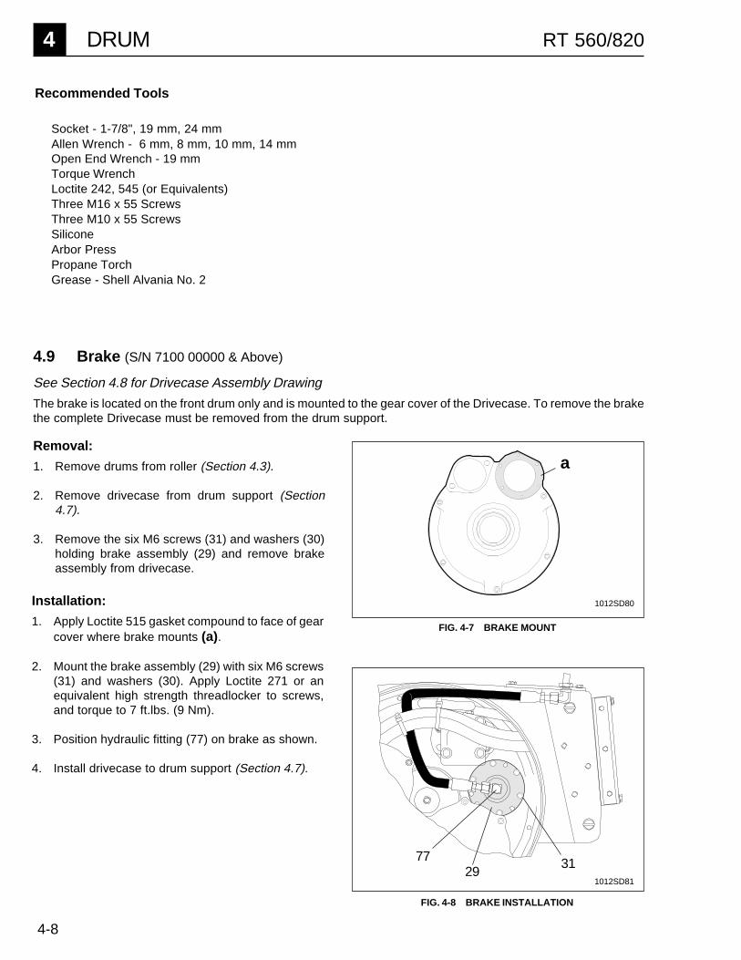
4-8
4 DRUM RT 560/820
Installation:
1. Apply Loctite 515 gasket compound to face of gearcover where brake mounts (a).
2. Mount the brake assembly (29) with six M6 screws(31) and washers (30). Apply Loctite 271 or anequivalent high strength threadlocker to screws,and torque to 7 ft.lbs. (9 Nm).
3. Position hydraulic fitting (77) on brake as shown.
4. Install drivecase to drum support (Section 4.7).
31
FIG. 4-8 BRAKE INSTALLATION
2977
FIG. 4-7 BRAKE MOUNT
Recommended Tools
Socket - 1-7/8", 19 mm, 24 mmAllen Wrench - 6 mm, 8 mm, 10 mm, 14 mmOpen End Wrench - 19 mmTorque WrenchLoctite 242, 545 (or Equivalents)Three M16 x 55 ScrewsThree M10 x 55 ScrewsSiliconeArbor PressPropane TorchGrease - Shell Alvania No. 2
1012SD81
a
1012SD80
4.9 Brake (S/N 7100 00000 & Above)
See Section 4.8 for Drivecase Assembly Drawing
The brake is located on the front drum only and is mounted to the gear cover of the Drivecase. To remove the brakethe complete Drivecase must be removed from the drum support.
Removal:
1. Remove drums from roller (Section 4.3).
2. Remove drivecase from drum support (Section4.7).
3. Remove the six M6 screws (31) and washers (30)holding brake assembly (29) and remove brakeassembly from drivecase.
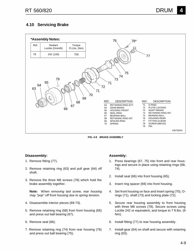
4-9
DRUM 4RT 560/820
4.10 Servicing Brake
6768
6970
7172
7173
7475
76 78*
77
Disassembly:
1. Remove fitting (77).
2. Remove retaining ring (63) and pull gear (64) offshaft.
3. Remove the three M6 screws (78) which hold thebrake assembly together.
Note: When removing last screw, rear housingmay "pop" off front housing due to spring tension.
4. Disassemble interior pieces (69-73).
5. Remove retaining ring (68) from front housing (65)and press out ball bearing (67).
6. Remove seal (66).
7. Remove retaining ring (74) from rear housing (76)and press out ball bearing (75).
FIG. 4-9 BRAKE ASSEMBLY
63 RETAINING RING-EXT.64 GEAR-BRAKE65 HOUSING-FRONT66 SEAL-RING67 BEARING-BALL68 RETAINING RING-INT.69 SPACER-RING70 SPRING
71 O-RING72 PLATE-LOCKING73 SHAFT-BRAKE74 RETAINING RING-INT.75 BEARING-BALL76 HOUSING-REAR77 FITTING-ELBOW78 SCREW (M6X25)79 PIN
Assembly:
1. Press bearings (67, 75) into front and rear hous-ings and secure in place using retaining rings (68,74).
2. Install seal (66) into front housing (65).
3. Insert ring spacer (69) into front housing.
4. Set front housing on face and insert spring (70), O-rings (71), shaft (73) and locking plate (72).
5. Secure rear housing assembly to front housingwith three M6 screws (78). Secure screws usingLoctite 242 or equivalent, and torque to 7 ft.lbs. (9Nm).
6. Install fitting (77) to rear housing assembly.
7. Install gear (64) on shaft and secure with retainingring (63).
*Assembly Notes:
Ref. Sealant TorqueLoctite (Omnifit) Ft.Lbs. (Nm)
78 242 (100) 7(9)
REF. DESCRIPTION REF. DESCRIPTION
6564
63
66
1007SD54
79
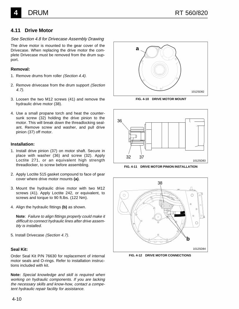
4-10
4 DRUM RT 560/820
4.11 Drive Motor
See Section 4.8 for Drivecase Assembly Drawing
The drive motor is mounted to the gear cover of theDrivecase. When replacing the drive motor the com-plete Drivecase must be removed from the drum sup-port.
Removal:
1. Remove drums from roller (Section 4.4).
2. Remove drivecase from the drum support (Section4.7).
3. Loosen the two M12 screws (41) and remove thehydraulic drive motor (38).
4. Use a small propane torch and heat the counter-sunk screw (32) holding the drive pinion to themotor. This will break down the threadlocking seal-ant. Remove screw and washer, and pull drivepinion (37) off motor.
a
3732
36
FIG. 4-11 DRIVE MOTOR PINION INSTALLATION
FIG. 4-10 DRIVE MOTOR MOUNT
b
38
FIG. 4-12 DRIVE MOTOR CONNECTIONS
1012SD82
1012SD83
1012SD84
Installation:
1. Install drive pinion (37) on motor shaft. Secure inplace with washer (36) and screw (32). ApplyLoctite 271, or an equivalent high strengththreadlocker, to screw before assembling.
2. Apply Loctite 515 gasket compound to face of gearcover where drive motor mounts (a).
3. Mount the hydraulic drive motor with two M12screws (41). Apply Loctite 242, or equivalent, toscrews and torque to 90 ft.lbs. (122 Nm).
4. Align the hydraulic fittings (b) as shown.
Note: Failure to align fittings properly could make itdifficult to connect hydraulic lines after drive assem-bly is installed.
5. Install Drivecase (Section 4.7).
Seal Kit:
Order Seal Kit P/N 76630 for replacement of internalmotor seals and O-rings. Refer to installation instruc-tions included with kit.
Note: Special knowledge and skill is required whenworking on hydraulic components. If you are lackingthe necessary skills and know-how, contact a compe-tent hydraulic repair facility for assistance.
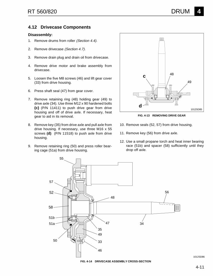
4-11
DRUM 4RT 560/820
4.12 Drivecase Components
Disassembly:
1. Remove drums from roller (Section 4.4).
2. Remove drivecase (Section 4.7).
3. Remove drain plug and drain oil from drivecase.
4. Remove drive motor and brake assembly fromdrivecase.
5. Loosen the five M8 screws (46) and lift gear cover(33) from drive housing.
6. Press shaft seal (47) from gear cover.
7. Remove retaining ring (48) holding gear (49) todrive axle (34). Use three M12 x 90 hardened bolts(c) (P/N 11411) to push drive gear from drivehousing and off of drive axle. If necessary, heatgear to aid in its removal.
8. Remove key (35) from drive axle and pull axle fromdrive housing. If necessary, use three M16 x 55screws (d) (P/N 11518) to push axle from drivehousing.
9. Remove retaining ring (50) and press roller bear-ing cage (51a) from drive housing.
FIG. 4-14 DRIVECASE ASSEMBLY CROSS-SECTION
56
55
46
33
35
52
57
50
47
48
34
58
1012SD86
49
51a
51b
1012SD85
c 48
49
d
10. Remove seals (52, 57) from drive housing.
11. Remove key (56) from drive axle.
12. Use a small propane torch and heat inner bearingrace (51b) and spacer (58) sufficiently until theydrop off axle.
FIG. 4-13 REMOVING DRIVE GEAR
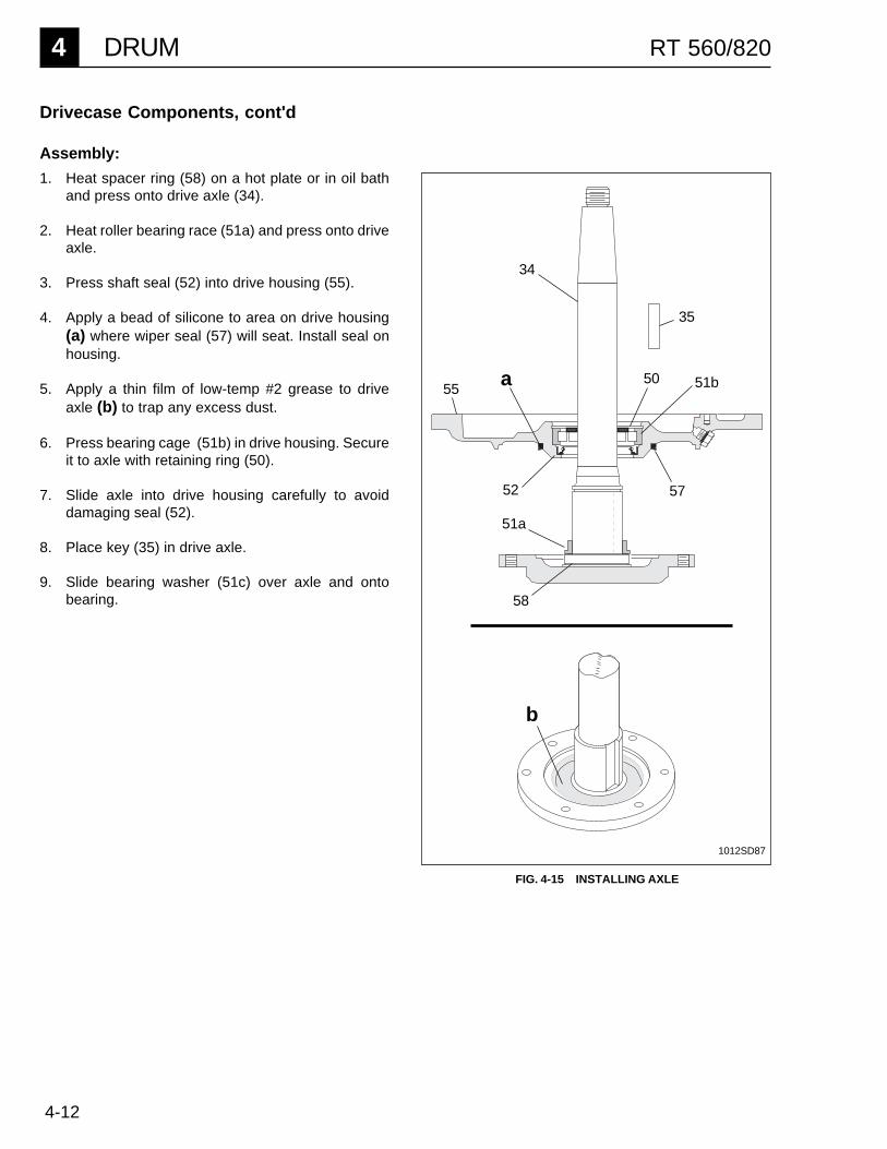
4-12
4 DRUM RT 560/820
Drivecase Components, cont'd
Assembly:
1. Heat spacer ring (58) on a hot plate or in oil bathand press onto drive axle (34).
2. Heat roller bearing race (51a) and press onto driveaxle.
3. Press shaft seal (52) into drive housing (55).
4. Apply a bead of silicone to area on drive housing(a) where wiper seal (57) will seat. Install seal onhousing.
5. Apply a thin film of low-temp #2 grease to driveaxle (b) to trap any excess dust.
6. Press bearing cage (51b) in drive housing. Secureit to axle with retaining ring (50).
7. Slide axle into drive housing carefully to avoiddamaging seal (52).
8. Place key (35) in drive axle.
9. Slide bearing washer (51c) over axle and ontobearing.
a
51a
51b
52 57
FIG. 4-15 INSTALLING AXLE
b
1012SD87
50
35
58
34
55
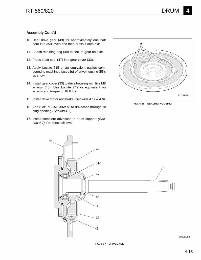
4-13
DRUM 4RT 560/820
FIG. 4-16 SEALING HOUSING
1012SD88
c
Assembly Cont'd
51c
48
47
46
49
33
35
10. Heat drive gear (49) for approximately one halfhour in a 350o oven and then press it onto axle.
11. Attach retaining ring (48) to secure gear on axle.
12. Press shaft seal (47) into gear cover (33).
13. Apply Loctite 515 or an equivalent gasket com-pound to machined faces (c) of drive housing (55),as shown.
14. Install gear cover (33) to drive housing with five M8screws (46). Use Loctite 242 or equivalent onscrews and torque to 18 ft.lbs.
15. Install drive motor and brake (Sections 4.11 & 4.9).
16. Add 8 oz. of SAE 30W oil to drivecase through fillplug opening (Section 4.7).
17. Install complete drivecase in drum support (Sec-tion 4.7). Re-check oil level.
55
1012SD89
FIG. 4-17 DRIVECASE
56

4-14
4 DRUM RT 560/820
NOTES
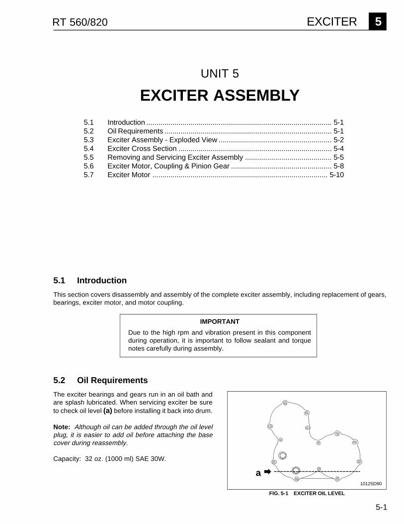
5-1
EXCITER 5RT 560/820
FIG. 5-1 EXCITER OIL LEVEL
5.1 Introduction
This section covers disassembly and assembly of the complete exciter assembly, including replacement of gears,bearings, exciter motor, and motor coupling.
UNIT 5
EXCITER ASSEMBLY
5.1 Introduction ............................................................................................ 5-15.2 Oil Requirements ................................................................................... 5-15.3 Exciter Assembly - Exploded View ........................................................ 5-25.4 Exciter Cross Section ............................................................................ 5-45.5 Removing and Servicing Exciter Assembly ........................................... 5-55.6 Exciter Motor, Coupling & Pinion Gear .................................................. 5-85.7 Exciter Motor ....................................................................................... 5-10
1012SD90
Due to the high rpm and vibration present in this componentduring operation, it is important to follow sealant and torquenotes carefully during assembly.
IMPORTANT
5.2 Oil Requirements
The exciter bearings and gears run in an oil bath andare splash lubricated. When servicing exciter be sureto check oil level (a) before installing it back into drum.
Note: Although oil can be added through the oil levelplug, it is easier to add oil before attaching the basecover during reassembly.
Capacity: 32 oz. (1000 ml) SAE 30W.
a

5-2
5 EXCITER RT 560/820
5.3 Exciter Assembly - Exploded view
7
5
1213
1112
1415
15
1617
16
4025*
39*
27
27
28*2930
3122
24*23*22
20*21*
4
3
2
9*10
6*
7
34
33
37
32
35*36*
36*
19
26*
26*
18
11
8
6*
1007SD80
1*
38*

5-3
EXCITER 5RT 560/820
Exciter Components
1 Fitting-elbow 12 O-Ring 13 O-Ring 14 Motor-hyd. gear 15 Key-Woodruff 16 Fitting-elbow 27 O-Ring 28 O-Ring 29 Screw (M10x25) 2
10 Washer-lock 211 Coupling-flexshaft 112 Setscrew (5/16"x5/8) 213 Sleeve-coupler 114 Retaining ring-ext. 115 Bearing-roller 216 Retaining ring-int. 217 Spacer-bearing 118 Key-Woodruff (¼x1) 119 Gear-pinion 120 Screw (M8x18) 1221 Cover 222 Bearing-roller 423 Cover-exciter base 124 Screw (M6x10) 1025 Screw (M8x16) 1326 Plug (M26x1.5) 227 Seal-ring 228 Cover-exciter gear 129 Retaining ring 230 Gear-exciter 231 Retaining ring-int. 232 Weight-variable 233 Shaft-exciter 234 Key 235 Screw (M10x30) 436 Mount-weight 237 Weight-exciter 438 Screw (M16x70) 439 Screw (M10x12) 140 Seal-ring 1
Ref. Description Qty. *Assembly Notes
Ref. Sealant TorqueLoctite (Omnifit) Ft.Lbs. (Nm)
1 545 (50) --6 545 (50) --9 242 (100) 36 (49)20 242 (100) 18 (24)21 515 (10) --23 515 (10) --24 242 (100) 7 (10)25 242 (100) 18 (24)26 222 (50) 36 (49)28 515 --35 271 (220) 36 (49)38 271 (220) 155 (210)39 515 36 (49)
36 Mounts must be installed on weightsas shown on page 5-7.
Recommended Tools
Socket - 17 mm, 19 mm, 24 mmAllen Wrench - 4 mm, 6 mm, 8 mm, 10 mm, 14 mmOpen End Wrench - 19 mmTorque WrenchLoctite 242, 271, 427, 545, 515 (or Equivalents)Three M16 x 55 ScrewsSnap Ring PliersArbor PressRubber MalletGear Puller

5-4
5 EXCITER RT 560/820
5.4 Exciter Cross Section
Note: Refer to Exciter Components on previous page for item numbers.
30
34
29
31
22
25 24 23 32 38 37
3635
131114 11
19
15
16
25 151617 12 10 9 4
1812 5
33
22
20
21
1012SD91
28
26
26
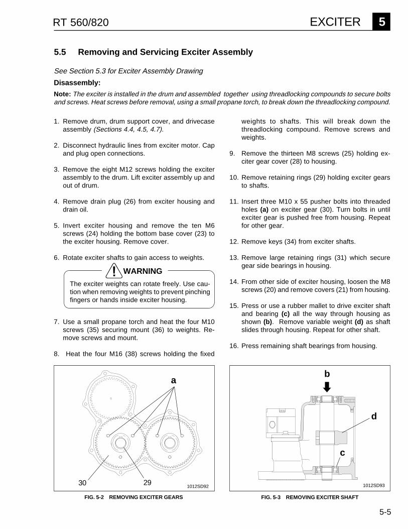
5-5
EXCITER 5RT 560/820
5.5 Removing and Servicing Exciter Assembly
1012SD92 1012SD93
FIG. 5-2 REMOVING EXCITER GEARS FIG. 5-3 REMOVING EXCITER SHAFT
See Section 5.3 for Exciter Assembly Drawing
Disassembly:
Note: The exciter is installed in the drum and assembled together using threadlocking compounds to secure boltsand screws. Heat screws before removal, using a small propane torch, to break down the threadlocking compound.
a
30 29
b
c
d
1. Remove drum, drum support cover, and drivecaseassembly (Sections 4.4, 4.5, 4.7).
2. Disconnect hydraulic lines from exciter motor. Capand plug open connections.
3. Remove the eight M12 screws holding the exciterassembly to the drum. Lift exciter assembly up andout of drum.
4. Remove drain plug (26) from exciter housing anddrain oil.
5. Invert exciter housing and remove the ten M6screws (24) holding the bottom base cover (23) tothe exciter housing. Remove cover.
6. Rotate exciter shafts to gain access to weights.
7. Use a small propane torch and heat the four M10screws (35) securing mount (36) to weights. Re-move screws and mount.
8. Heat the four M16 (38) screws holding the fixed
weights to shafts. This will break down thethreadlocking compound. Remove screws andweights.
9. Remove the thirteen M8 screws (25) holding ex-citer gear cover (28) to housing.
10. Remove retaining rings (29) holding exciter gearsto shafts.
11. Insert three M10 x 55 pusher bolts into threadedholes (a) on exciter gear (30). Turn bolts in untilexciter gear is pushed free from housing. Repeatfor other gear.
12. Remove keys (34) from exciter shafts.
13. Remove large retaining rings (31) which securegear side bearings in housing.
14. From other side of exciter housing, loosen the M8screws (20) and remove covers (21) from housing.
15. Press or use a rubber mallet to drive exciter shaftand bearing (c) all the way through housing asshown (b). Remove variable weight (d) as shaftslides through housing. Repeat for other shaft.
16. Press remaining shaft bearings from housing.
WARNING
The exciter weights can rotate freely. Use cau-tion when removing weights to prevent pinchingfingers or hands inside exciter housing.
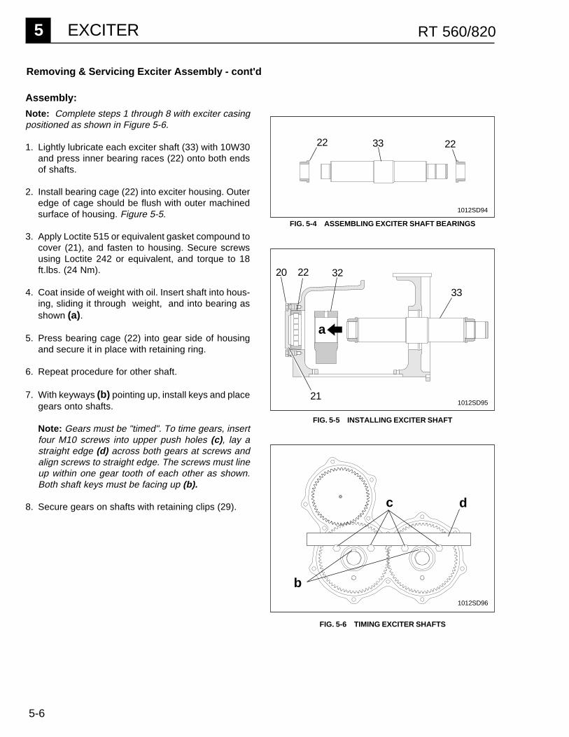
5-6
5 EXCITER RT 560/820
Removing & Servicing Exciter Assembly - cont'd
c d
32
33
a
20 22
21
FIG. 5-4 ASSEMBLING EXCITER SHAFT BEARINGS
FIG. 5-5 INSTALLING EXCITER SHAFT
FIG. 5-6 TIMING EXCITER SHAFTS
Assembly:
Note: Complete steps 1 through 8 with exciter casingpositioned as shown in Figure 5-6.
1. Lightly lubricate each exciter shaft (33) with 10W30and press inner bearing races (22) onto both endsof shafts.
2. Install bearing cage (22) into exciter housing. Outeredge of cage should be flush with outer machinedsurface of housing. Figure 5-5.
3. Apply Loctite 515 or equivalent gasket compound tocover (21), and fasten to housing. Secure screwsusing Loctite 242 or equivalent, and torque to 18ft.lbs. (24 Nm).
4. Coat inside of weight with oil. Insert shaft into hous-ing, sliding it through weight, and into bearing asshown (a).
5. Press bearing cage (22) into gear side of housingand secure it in place with retaining ring.
6. Repeat procedure for other shaft.
7. With keyways (b) pointing up, install keys and placegears onto shafts.
Note: Gears must be "timed". To time gears, insertfour M10 screws into upper push holes (c), lay astraight edge (d) across both gears at screws andalign screws to straight edge. The screws must lineup within one gear tooth of each other as shown.Both shaft keys must be facing up (b).
8. Secure gears on shafts with retaining clips (29).
33 2222
1012SD94
1012SD95
1012SD96
b
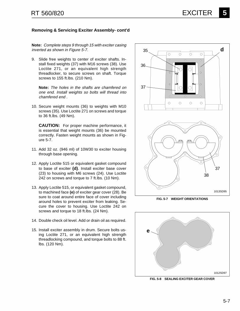
5-7
EXCITER 5RT 560/820
Removing & Servicing Exciter Assembly- cont'd
1013SD95
35
36
37
38
d
FIG. 5-7 WEIGHT ORIENTATIONS
e
1012SD97
FIG. 5-8 SEALING EXCITER GEAR COVER
37
Note: Complete steps 9 through 15 with exciter casinginverted as shown in Figure 5-7.
9. Slide free weights to center of exciter shafts. In-stall fixed weights (37) with M16 screws (38). UseLoctite 271, or an equivalent high strengththreadlocker, to secure screws on shaft. Torquescrews to 155 ft.lbs. (210 Nm).
Note: The holes in the shafts are chamfered onone end. Install weights so bolts will thread intochamfered end .
10. Secure weight mounts (36) to weights with M10screws (35). Use Loctite 271 on screws and torqueto 36 ft.lbs. (49 Nm).
CAUTION: For proper machine performance, itis essential that weight mounts (36) be mountedcorrectly. Fasten weight mounts as shown in Fig-ure 5-7.
11. Add 32 oz. (946 ml) of 10W30 to exciter housingthrough base opening.
12. Apply Loctite 515 or equivalent gasket compoundto base of exciter (d). Install exciter base cover(23) to housing with M6 screws (24). Use Loctite242 on screws and torque to 7 ft.lbs. (10 Nm).
13. Apply Loctite 515, or equivalent gasket compound,to machined face (e) of exciter gear cover (28). Besure to coat around entire face of cover includingaround holes to prevent exciter from leaking. Se-cure the cover to housing. Use Loctite 242 onscrews and torque to 18 ft.lbs. (24 Nm).
14. Double check oil level. Add or drain oil as required.
15. Install exciter assembly in drum. Secure bolts us-ing Loctite 271, or an equivalent high strengththreadlocking compound, and torque bolts to 88 ft.lbs. (120 Nm).
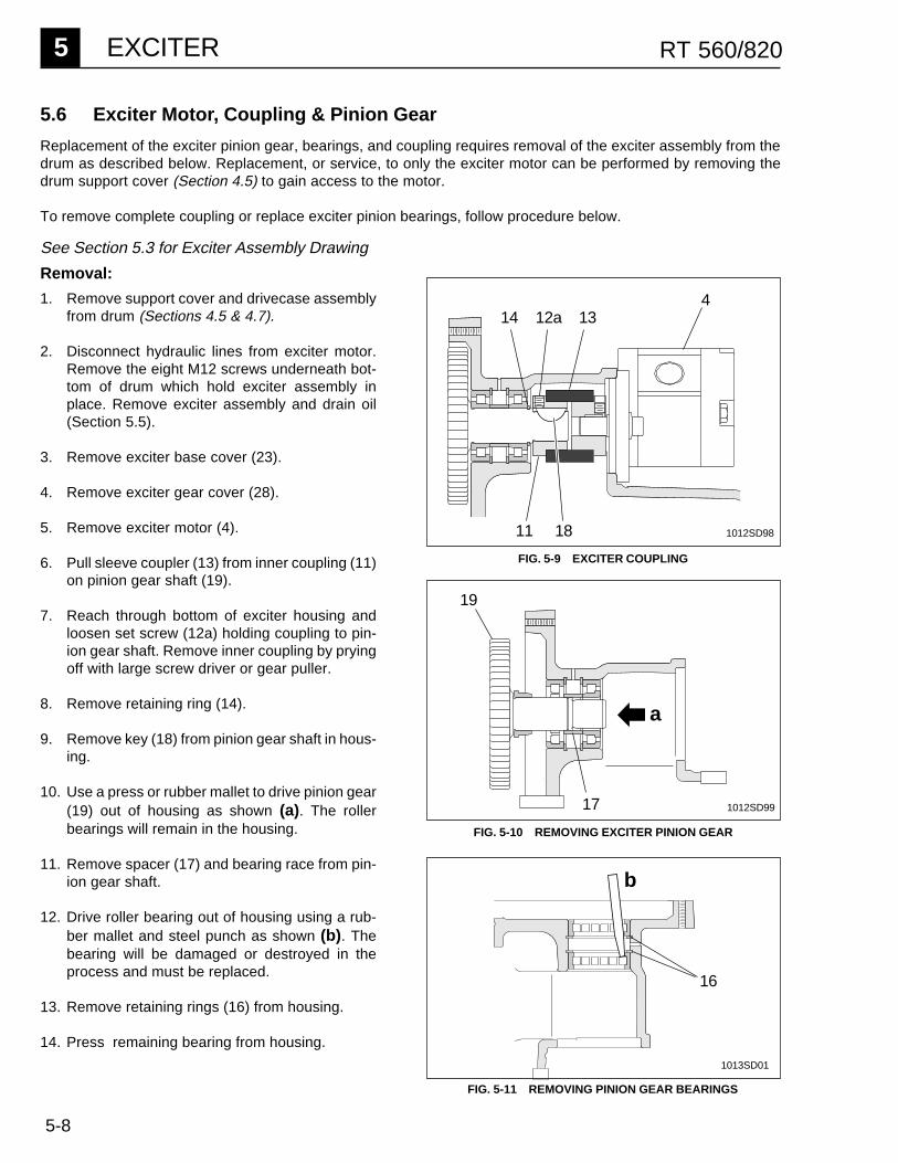
5-8
5 EXCITER RT 560/820
See Section 5.3 for Exciter Assembly Drawing
Removal:
1. Remove support cover and drivecase assemblyfrom drum (Sections 4.5 & 4.7).
2. Disconnect hydraulic lines from exciter motor.Remove the eight M12 screws underneath bot-tom of drum which hold exciter assembly inplace. Remove exciter assembly and drain oil(Section 5.5).
3. Remove exciter base cover (23).
4. Remove exciter gear cover (28).
5. Remove exciter motor (4).
6. Pull sleeve coupler (13) from inner coupling (11)on pinion gear shaft (19).
7. Reach through bottom of exciter housing andloosen set screw (12a) holding coupling to pin-ion gear shaft. Remove inner coupling by pryingoff with large screw driver or gear puller.
8. Remove retaining ring (14).
9. Remove key (18) from pinion gear shaft in hous-ing.
10. Use a press or rubber mallet to drive pinion gear(19) out of housing as shown (a). The rollerbearings will remain in the housing.
11. Remove spacer (17) and bearing race from pin-ion gear shaft.
12. Drive roller bearing out of housing using a rub-ber mallet and steel punch as shown (b). Thebearing will be damaged or destroyed in theprocess and must be replaced.
13. Remove retaining rings (16) from housing.
14. Press remaining bearing from housing.
5.6 Exciter Motor, Coupling & Pinion Gear
Replacement of the exciter pinion gear, bearings, and coupling requires removal of the exciter assembly from thedrum as described below. Replacement, or service, to only the exciter motor can be performed by removing thedrum support cover (Section 4.5) to gain access to the motor.
To remove complete coupling or replace exciter pinion bearings, follow procedure below.
17
19
41312a14
11 18
16
a
b
FIG. 5-9 EXCITER COUPLING
FIG. 5-10 REMOVING EXCITER PINION GEAR
FIG. 5-11 REMOVING PINION GEAR BEARINGS
1012SD98
1012SD99
1013SD01
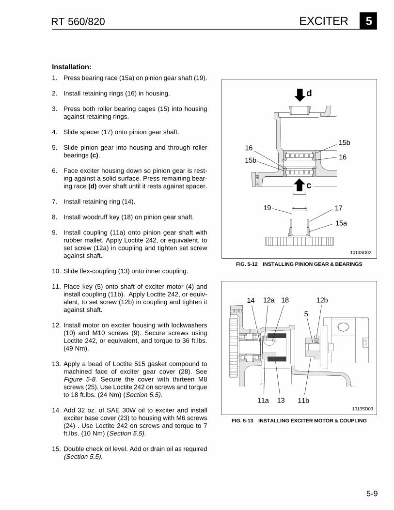
5-9
EXCITER 5RT 560/820
Installation:
1. Press bearing race (15a) on pinion gear shaft (19).
2. Install retaining rings (16) in housing.
3. Press both roller bearing cages (15) into housingagainst retaining rings.
4. Slide spacer (17) onto pinion gear shaft.
5. Slide pinion gear into housing and through rollerbearings (c).
6. Face exciter housing down so pinion gear is rest-ing against a solid surface. Press remaining bear-ing race (d) over shaft until it rests against spacer.
7. Install retaining ring (14).
8. Install woodruff key (18) on pinion gear shaft.
9. Install coupling (11a) onto pinion gear shaft withrubber mallet. Apply Loctite 242, or equivalent, toset screw (12a) in coupling and tighten set screwagainst shaft.
10. Slide flex-coupling (13) onto inner coupling.
11. Place key (5) onto shaft of exciter motor (4) andinstall coupling (11b). Apply Loctite 242, or equiv-alent, to set screw (12b) in coupling and tighten itagainst shaft.
12. Install motor on exciter housing with lockwashers(10) and M10 screws (9). Secure screws usingLoctite 242, or equivalent, and torque to 36 ft.lbs.(49 Nm).
13. Apply a bead of Loctite 515 gasket compound tomachined face of exciter gear cover (28). SeeFigure 5-8. Secure the cover with thirteen M8screws (25). Use Loctite 242 on screws and torqueto 18 ft.lbs. (24 Nm) (Section 5.5).
14. Add 32 oz. of SAE 30W oil to exciter and installexciter base cover (23) to housing with M6 screws(24) . Use Loctite 242 on screws and torque to 7ft.lbs. (10 Nm) (Section 5.5).
15. Double check oil level. Add or drain oil as required(Section 5.5).
c
d
15a
19 17
15b
1615b
16
14 1812a 12b
5
11b11a 13
FIG. 5-13 INSTALLING EXCITER MOTOR & COUPLING
FIG. 5-12 INSTALLING PINION GEAR & BEARINGS
1013SD02
1013SD03
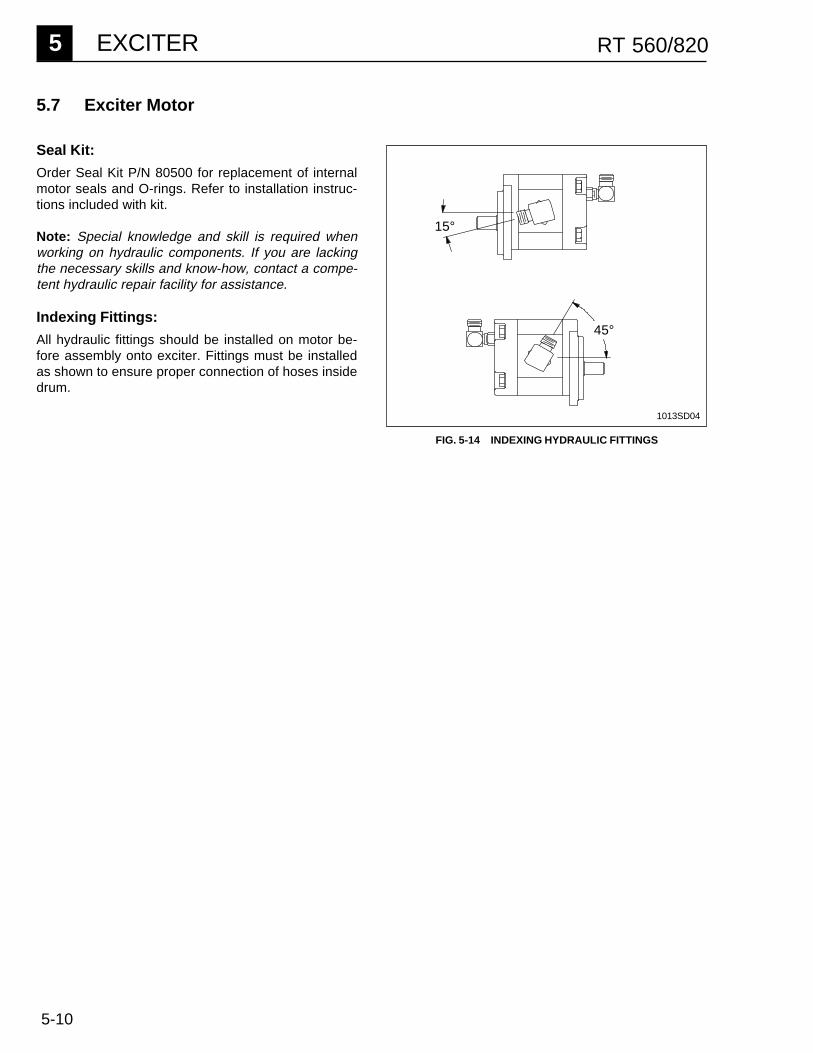
5-10
5 EXCITER RT 560/820
5.7 Exciter Motor
Seal Kit:
Order Seal Kit P/N 80500 for replacement of internalmotor seals and O-rings. Refer to installation instruc-tions included with kit.
Note: Special knowledge and skill is required whenworking on hydraulic components. If you are lackingthe necessary skills and know-how, contact a compe-tent hydraulic repair facility for assistance.
Indexing Fittings:
All hydraulic fittings should be installed on motor be-fore assembly onto exciter. Fittings must be installedas shown to ensure proper connection of hoses insidedrum.
FIG. 5-14 INDEXING HYDRAULIC FITTINGS
15°
45°
1013SD04

6-1
FRAME 6RT 560/820
6.1 Shockmount Installation Exploded View ................................................ 6-16.2 Replacing Shockmounts ........................................................................ 6-26.3 Hydraulic Hose Clamps ......................................................................... 6-46.4 Drum Supports ...................................................................................... 6-56.5 Articulated Joint & Steering Cylinder - Exploded View .......................... 6-76.6 Articulated Joint ..................................................................................... 6-86.7 Steering Cylinder ................................................................................. 6-10
UNIT 6
FRAME
REF. DESCRIPTION QTY.
1 FRAME-REAR 12 DRUM SUPPORT 13 SPACER 64 SHOCKMOUNT 65 WASHER-LOCK 246 SCREW (M12X25) 247 BRACKET-SHOCKMOUNT 48 SETSCREW (M12X30) 129 STUD-SHOCKMOUNT 6
Shockmount Components
*Assembly Notes
Ref. Sealant TorqueLoctite (Omnifit) Ft.Lbs. (Nm)
3 242 (100) ---5 242 (100) 63 (85)6 242 (100) 36 (49)8 242 (100) ---9 242 (100) ---
1
43*
5*
78* 2
4
8*3*
9*6
5*
6*
6.1 Shockmount Installation - Exploded View
1013SD05
6*5*
5*
6*
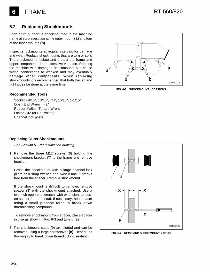
6-2
6 FRAME RT 560/820
6.2 Replacing Shockmounts
Each drum support is shockmounted to the machineframe at six places, two at the outer mount (a) and fourat the inner mounts (b).
Inspect shockmounts at regular intervals for damageand wear. Replace shockmounts that are torn or split.The shockmounts isolate and protect the frame andupper components from excessive vibration. Runningthe machine with damaged shockmounts can causewiring connections to weaken and may eventuallydamage other components. When replacingshockmounts it is recommended that both the left andright sides be done at the same time.
Recommended Tools
Socket - 9/16", 13/16", 7/8", 15/16", 1-1/16"Open End Wrench - 2"Rubber Mallet , Torque WrenchLoctite 242 (or Equivalent)Channel lock pliers
a
b
a
b
Replacing Outer Shockmounts:
See Section 6.1 for installation drawing.
1. Remove the three M12 screws (6) holding theshockmount bracket (7) to the frame and removebracket.
2. Grasp the shockmount with a large channel-lockpliers or a strap wrench and twist it until it breaksfree from the spacer. Remove shockmount.
If the shockmount is difficult to remove, removespacer (3) with the shockmount attached. Use atwo-inch open end wrench, with extension, to loos-en spacer from the stud. If necessary, heat spacerusing a small propane torch to break downthreadlocking compound.
To remove shockmount from spacer, place spacerin vise as shown in Fig. 6-3 and turn it free.
3. The shockmount studs (9) are slotted and can beremoved using a large screwdriver (c). Heat studsthoroughly to break down threadlocking sealant.
FIG. 6-1 SHOCKMOUNT LOCATIONS
1007SD22
c9
4 3
FIG. 6-2 REMOVING SHOCKMOUNT & STUD
1013SD06
x x

6-3
FRAME 6RT 560/820
Replacing Inner Shockmounts:
See Section 6.1 installation drawing.
1. Lock articulated joint (Section 1.5).
2. Support machine with appropriate crane or hoist bythe lifting eye (e).
3. Loosen (do not remove) the M12 screws (6) holdingouter shockmount (g) to the shockmount bracket.
4. Remove the M12 (6) screws holding the innershockmounts (f) to the frame.
5. Slowly raise machine and allow drum support topivot down as shown in illustration. Position ma-chine and drum support as needed to access innershockmounts and spacers.
CAUTION: Avoid straining hydraulic hoses. Liftmachine only high enough to remove shockmounts.
Remove and install shockmounts and spacers in samemanner as described on page 6-2, steps two andthree.
After shockmounts have been installed:
1. Lower machine and position support drum to alignshockmounts with holes in frame.
2. Mount washer (5) to M12 screw (6) and applyLoctite 242 to screw. Insert screw through frameand into shockmount. Torque screws to 36 ft.lbs.(49 Nm).
3. Tighten outer bracket.
e
g
FIG. 6-3 USING VISE TO REMOVE SHOCKMOUNT
FIG. 6-4 REMOVING INNER SHOCKMOUNTS
1013SD08
f1013SD09
When installing shockmounts, apply Loctite 242, or anequivalent threadlocking compound, to shockmountfasteners during assembly.
If replacing shockmount stud (9), apply Loctite 242, oran equivalent threadlocking compound, to threads onstud. Screw stud into frame until it protrudes equally oneither side (x).
Torque fasteners following assembly notes on page 6-1.

6-4
6 FRAME RT 560/820
6.3 Hydraulic Hose Clamps
10* 11* 24
17
23 13 12*
17
2314
12* 13
2022
14
19*
21
18
17
15
16
14
15
13
1009SD72
Hydraulic Hose Clamp Components
REF. DESCRIPTION QTY.
10 SCREW M8 X 202 211 PLATE, COVER 112 SCREW M8 X 60 613 WASHER 614 NUT-LOCK M6 715 PLATE-CLAMPING 216 CLAMP-HOSE 117 SCREW M6 X 50 7
13
*Assembly Notes
Ref. SealantLoctite (Omnifit)
10 242 (100)11 515 (10)12 242 (100)19 242 (100)
REF. DESCRIPTION QTY.
18 GUARD, HOSE 119 SCREW M8 X 20 120 CLAMP-HOSE 121 ADAPTER-CLAMP 122 PLATE-CLAMPING 223 PLATE-CLAMPING 224 CLAMP-HOSE 1
12*
12*
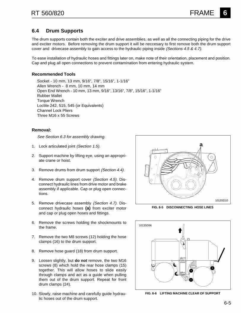
6-5
FRAME 6RT 560/820
Recommended Tools
Socket - 10 mm, 13 mm, 9/16", 7/8", 15/16", 1-1/16"Allen Wrench - 8 mm, 10 mm, 14 mmOpen End Wrench - 10 mm, 13 mm, 9/16", 13/16", 7/8", 15/16", 1-1/16"Rubber MalletTorque WrenchLoctite 242, 515, 545 (or Equivalents)Channel Lock PliersThree M16 x 55 Screws
6.4 Drum Supports
The drum supports contain both the exciter and drive assemblies, as well as all the connecting piping for the driveand exciter motors. Before removing the drum support it will be neccesary to first remove both the drum supportcover and drivecase assembly to gain access to the hydraulic piping inside (Sections 4.5 & 4.7).
To ease installation of hydraulic hoses and fittings later on, make note of their orientation, placement and position.Cap and plug all open connections to prevent contamination from entering hydraulic system.
Removal:
See Section 6.3 for assembly drawing.
1. Lock articulated joint (Section 1.5).
2. Support machine by lifting eye, using an appropri-ate crane or hoist.
3. Remove drums from drum support (Section 4.4).
4. Remove drum support cover (Section 4.5). Dis-connect hydraulic lines from drive motor and brakeassembly if applicable. Cap or plug open connec-tions.
5. Remove drivecase assembly (Section 4.7). Dis-connect hydraulic hoses (a) from exciter motorand cap or plug open hoses and fittings.
6. Remove the screws holding the shockmounts tothe frame.
7. Remove the two M8 screws (12) holding the hoseclamps (16) to the drum support.
8. Remove hose guard (18) from drum support.
9. Loosen slightly, but do not remove, the two M16screws (8) which hold the rear hose clamps (15)together. This will allow hoses to slide easilythrough clamps and act as a guide when pullingthem out of the drum support. Repeat for frontdrum clamps (24).
10. Slowly, raise machine and carefully guide hydrau-lic hoses out of the drum support.
a
FIG. 6-5 DISCONNECTING HOSE LINES
1013SD10
FIG. 6-6 LIFTING MACHINE CLEAR OF SUPPORT
1013SD96

6-6
6 FRAME RT 560/820
Drum Supports, Cont'd
Installation:
See Section 6.3 for assembly drawing.
1. Install shockmounts on drum support (Section6.2).
2. Place drum support under raised machine. Inserthydraulic lines through openings and lower ma-chine over drum support.
3. Secure machine frame to shockmounts.
4. Apply Loctite 545 hydraulic sealant, or equivalent,to fittings on exciter drive motor and attach hydrau-lic hoses.
5. Install drive housing assembly and connect hy-draulic lines to drive motor (Section 4.7).
6. With all hydraulic hoses connected, tighten hoseclamps (15, 24) around hoses. Install hose clampsto drum supports and attach hose guard (18).Secure all fasteners using Loctite 242 , or equiva-lent.
7. Install drum support cover and drums (Sections4.4 & 4.5).

6-7
FRAME 6RT 560/820
6.5 Articulated Joint & Steering Cylinder - Exploded View
REF. DESCRIPTION QTY.
28 NUT-LOCK (M16) 229 WASHER 230 BEARING-BALL 231 FITTING-GREASE 632 BRACKET-PIVOT 233 PIN-PIVOT 234 SCREW (M16X90) 235 SCREW (M12X40) 836 ACCESS COVER 137 SCREW (M8 X 16) 4
Sealant TorqueRef. Loctite (Omnifit) Ft.Lbs. (Nm)
28 --- 15535 271 (220) 94 (128)
*Assembly Notes
28*
37
36
30
31
32
29
33
3441
42
44
39
38
43
28*
29
30
31
32
34
33
1013SD13
REF. DESCRIPTION QTY.
38 SCREW (M12X20) 239 WASHER 2
FITTING-HYD. 240 O-RING 2
O-RING 241 HOSE ASSY. 142 HOSE ASSY 143 BEARING 244 CYLINDER-HYD. 1
31
4040
39
38
Joint & Steering Components
35*
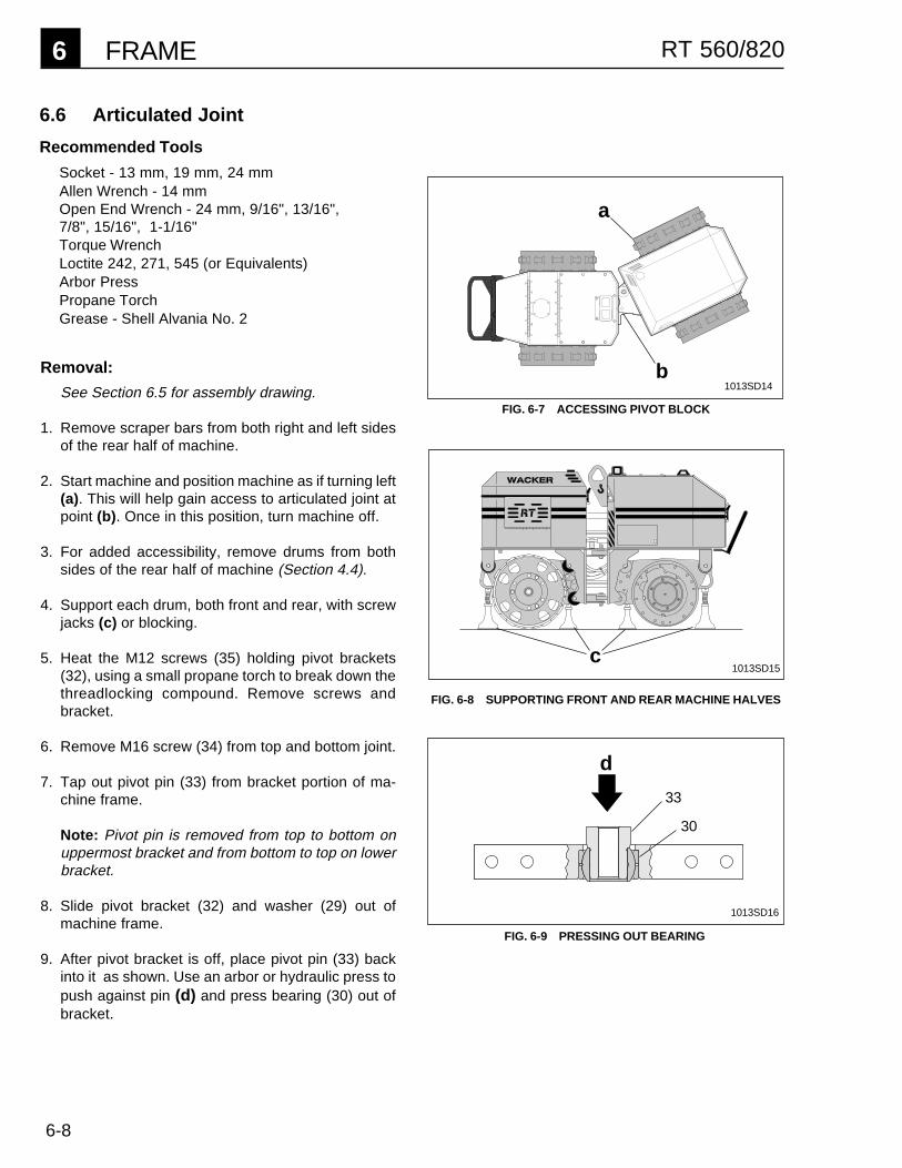
6-8
6 FRAME RT 560/820
Removal:
See Section 6.5 for assembly drawing.
1. Remove scraper bars from both right and left sidesof the rear half of machine.
2. Start machine and position machine as if turning left(a). This will help gain access to articulated joint atpoint (b). Once in this position, turn machine off.
3. For added accessibility, remove drums from bothsides of the rear half of machine (Section 4.4).
4. Support each drum, both front and rear, with screwjacks (c) or blocking.
5. Heat the M12 screws (35) holding pivot brackets(32), using a small propane torch to break down thethreadlocking compound. Remove screws andbracket.
6. Remove M16 screw (34) from top and bottom joint.
7. Tap out pivot pin (33) from bracket portion of ma-chine frame.
Note: Pivot pin is removed from top to bottom onuppermost bracket and from bottom to top on lowerbracket.
8. Slide pivot bracket (32) and washer (29) out ofmachine frame.
9. After pivot bracket is off, place pivot pin (33) backinto it as shown. Use an arbor or hydraulic press topush against pin (d) and press bearing (30) out ofbracket.
6.6 Articulated Joint
Recommended Tools
Socket - 13 mm, 19 mm, 24 mmAllen Wrench - 14 mmOpen End Wrench - 24 mm, 9/16", 13/16",7/8", 15/16", 1-1/16"Torque WrenchLoctite 242, 271, 545 (or Equivalents)Arbor PressPropane TorchGrease - Shell Alvania No. 2
b
a
FIG. 6-7 ACCESSING PIVOT BLOCK
c
FIG. 6-8 SUPPORTING FRONT AND REAR MACHINE HALVES
d
33
30
1013SD14
FIG. 6-9 PRESSING OUT BEARING
1013SD15
1013SD16

6-9
FRAME 6RT 560/820
30
29 28
33
34
34
33
30 28 29
32
Assembly:
1. To prevent rust, repaint any areas of the pivotbracket damaged by heating during disassembly.
2. Press bearings (30) into pivot brackets (32).
3. Place washer (29) into machine frame.
4. Slide (e) pivot bracket (32) over washer and intomachine frame.
5. Tap pivot pin (f) into bracket portion of machineframe and through pivot bracket.
Note: Pivot pin is installed from bottom to top onuppermost bracket and from top to bottom on lowerbracket.
6. Install M16 x 90 screw (34) and secure with locknut(28). Torque to 155 ft. lbs. (210 Nm).
1013SD18
FIG. 6-11 INSTALLING PIVOT BLOCKS
e
f29
7. Secure pivot bracket to rear half of machine framewith M12 x 40 screws (35). Use Loctite 271, or anequivalent high strength threadlocking compound,on screws and torque screws to 94 ft. lbs. (128Nm).
8. Attach drums and scraper bars (Section 4.4).
9. Grease bearing with Shell Alvania #2 grease.
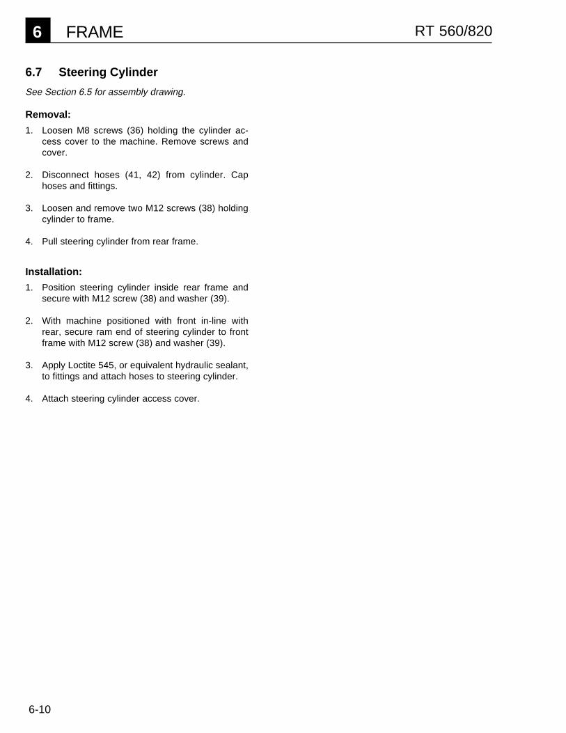
6-10
6 FRAME RT 560/820
6.7 Steering Cylinder
See Section 6.5 for assembly drawing.
Removal:
1. Loosen M8 screws (36) holding the cylinder ac-cess cover to the machine. Remove screws andcover.
2. Disconnect hoses (41, 42) from cylinder. Caphoses and fittings.
3. Loosen and remove two M12 screws (38) holdingcylinder to frame.
4. Pull steering cylinder from rear frame.
Installation:
1. Position steering cylinder inside rear frame andsecure with M12 screw (38) and washer (39).
2. With machine positioned with front in-line withrear, secure ram end of steering cylinder to frontframe with M12 screw (38) and washer (39).
3. Apply Loctite 545, or equivalent hydraulic sealant,to fittings and attach hoses to steering cylinder.
4. Attach steering cylinder access cover.

7-1
POWER TAKE-OFF 7RT 560/820
UNIT 7
POWER TAKE-OFF
7.1 Drive Pump & Coupling - Exploded View .............................................. 7-27.2 Pump & Coupling Installation ................................................................ 7-37.3 General Description ............................................................................... 7-47.4 Engine ................................................................................................... 7-4

7-2
7 POWER TAKE-OFF RT 560/820
7.1 Drive Pump & Coupling - Exploded View
REF. DESCRIPTION QTY.
1 STUD 62 WASHER-LOCK 63 NUT (M8) 64 BOLT 65 PLUG 16 MANIFOLD-SUCTION 17 SCREW (M6X50) 48 O-RING 19 PUMP-HYDRAULIC 110 FITTING-ADAPTER 211 O-RING 2
12 SCREW (M6X80) 413 BLOCK-HYDRAULIC 114 O-RING 215 SCREW (M6X40) 416 BLOCK-HYDRAULIC 117 SCREW (M10X30) 418 ADAPTER-PUMP 119 ADAPTER-INTERNAL 120 ADAPTER-ENGINE 121 SUPPORT-PUMP 1
REF. DESCRIPTION QTY.
10
1417*
1*
23
45
67*
8
13
14
16
1819
20
21
11
15*
TO PORT P2ON MAINMANIFOLD
TO PORT P1ON MAINMANIFOLD
REF. SEALANT TORQUELOCTITE (OMNIFIT) FT.LBS. (NM)
1 242 (100) ---7 271 (220) 7 (10)
12 271 (220) 7 (10)15 271 (220) 7 (10)17 271 (220) 36 (49)
1013SD19
9
12*
*Assembly Notes
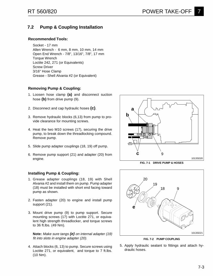
7-3
POWER TAKE-OFF 7RT 560/820
7.2 Pump & Coupling Installation
Removing Pump & Coupling:
1. Loosen hose clamp (a) and disconnect suctionhose (b) from drive pump (9).
2. Disconnect and cap hydraulic hoses (c).
3. Remove hydraulic blocks (6,13) from pump to pro-vide clearance for mounting screws.
4. Heat the two M10 screws (17), securing the drivepump, to break down the threadlocking compound.Remove pump.
5. Slide pump adapter couplings (18, 19) off pump.
6. Remove pump support (21) and adapter (20) fromengine.
Recommended Tools:
Socket - 17 mmAllen Wrench - 6 mm, 8 mm, 10 mm, 14 mmOpen End Wrench - 7/8", 13/16", 7/8", 17 mmTorque WrenchLoctite 242, 271 (or Equivalents)Screw Driver3/16" Hose ClampGrease - Shell Alvania #2 (or Equivalent)
b
FIG. 7-1 DRIVE PUMP & HOSES
9
a
c1013SD20
Installing Pump & Coupling:
1. Grease adapter couplings (18, 19) with ShellAlvania #2 and install them on pump. Pump adapter(18) must be installed with short end facing towardpump as shown.
2. Fasten adapter (20) to engine and install pumpsupport (21).
3. Mount drive pump (9) to pump support. Securemounting screws (17) with Loctite 271, or equiva-lent high strength threadlocker, and torque screwsto 36 ft.lbs. (49 Nm).
Note: Make sure tangs (e) on internal adapter (19)fit into slots in engine adapter (20).
4. Attach blocks (6, 13) to pump. Secure screws usingLoctite 271, or equivalent, and torque to 7 ft.lbs.(10 Nm).
5. Apply hydraulic sealant to fittings and attach hy-draulic hoses.
e
9
2019
18
FIG. 7-2 PUMP COUPLING
1013SD21
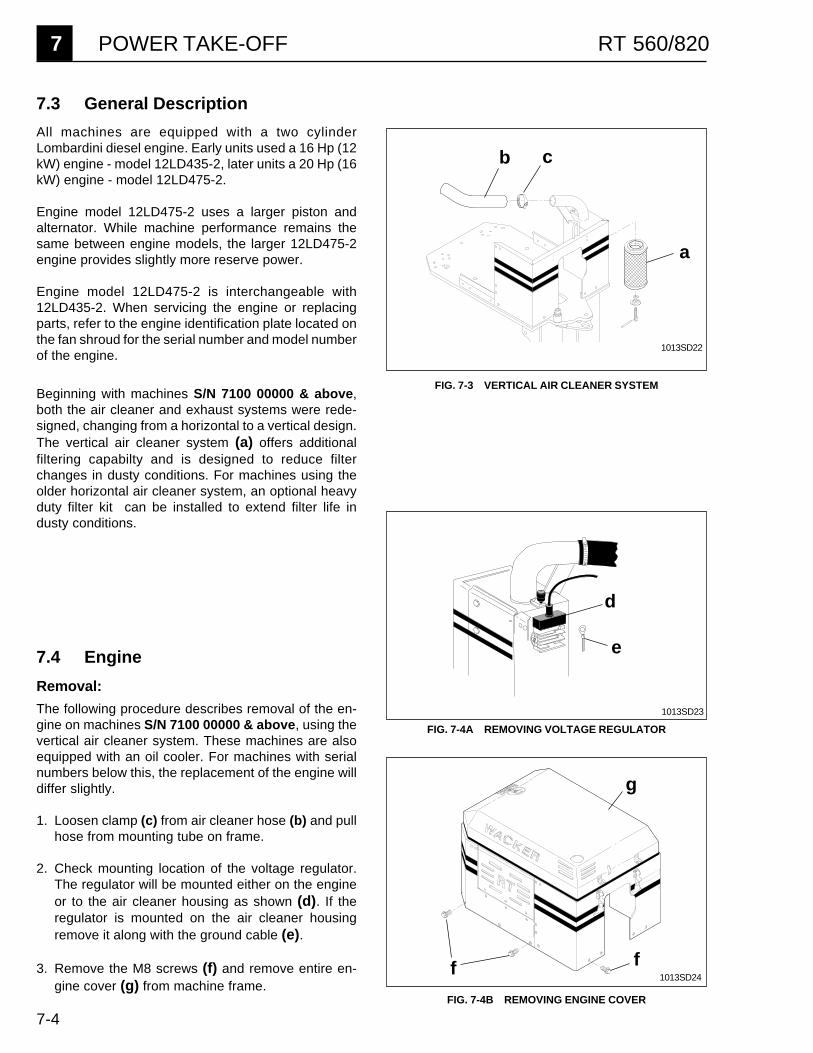
7-4
7 POWER TAKE-OFF RT 560/820
FIG. 7-4B REMOVING ENGINE COVER
f
g
f
FIG. 7-4A REMOVING VOLTAGE REGULATOR
a
b c
7.3 General Description
All machines are equipped with a two cylinderLombardini diesel engine. Early units used a 16 Hp (12kW) engine - model 12LD435-2, later units a 20 Hp (16kW) engine - model 12LD475-2.
Engine model 12LD475-2 uses a larger piston andalternator. While machine performance remains thesame between engine models, the larger 12LD475-2engine provides slightly more reserve power.
Engine model 12LD475-2 is interchangeable with12LD435-2. When servicing the engine or replacingparts, refer to the engine identification plate located onthe fan shroud for the serial number and model numberof the engine.
Beginning with machines S/N 7100 00000 & above,both the air cleaner and exhaust systems were rede-signed, changing from a horizontal to a vertical design.The vertical air cleaner system (a) offers additionalfiltering capabilty and is designed to reduce filterchanges in dusty conditions. For machines using theolder horizontal air cleaner system, an optional heavyduty filter kit can be installed to extend filter life industy conditions.
FIG. 7-3 VERTICAL AIR CLEANER SYSTEM
7.4 Engine
Removal:
The following procedure describes removal of the en-gine on machines S/N 7100 00000 & above, using thevertical air cleaner system. These machines are alsoequipped with an oil cooler. For machines with serialnumbers below this, the replacement of the engine willdiffer slightly.
1. Loosen clamp (c) from air cleaner hose (b) and pullhose from mounting tube on frame.
2. Check mounting location of the voltage regulator.The regulator will be mounted either on the engineor to the air cleaner housing as shown (d). If theregulator is mounted on the air cleaner housingremove it along with the ground cable (e).
3. Remove the M8 screws (f) and remove entire en-gine cover (g) from machine frame.
1013SD22
1013SD23
1013SD24
d
e
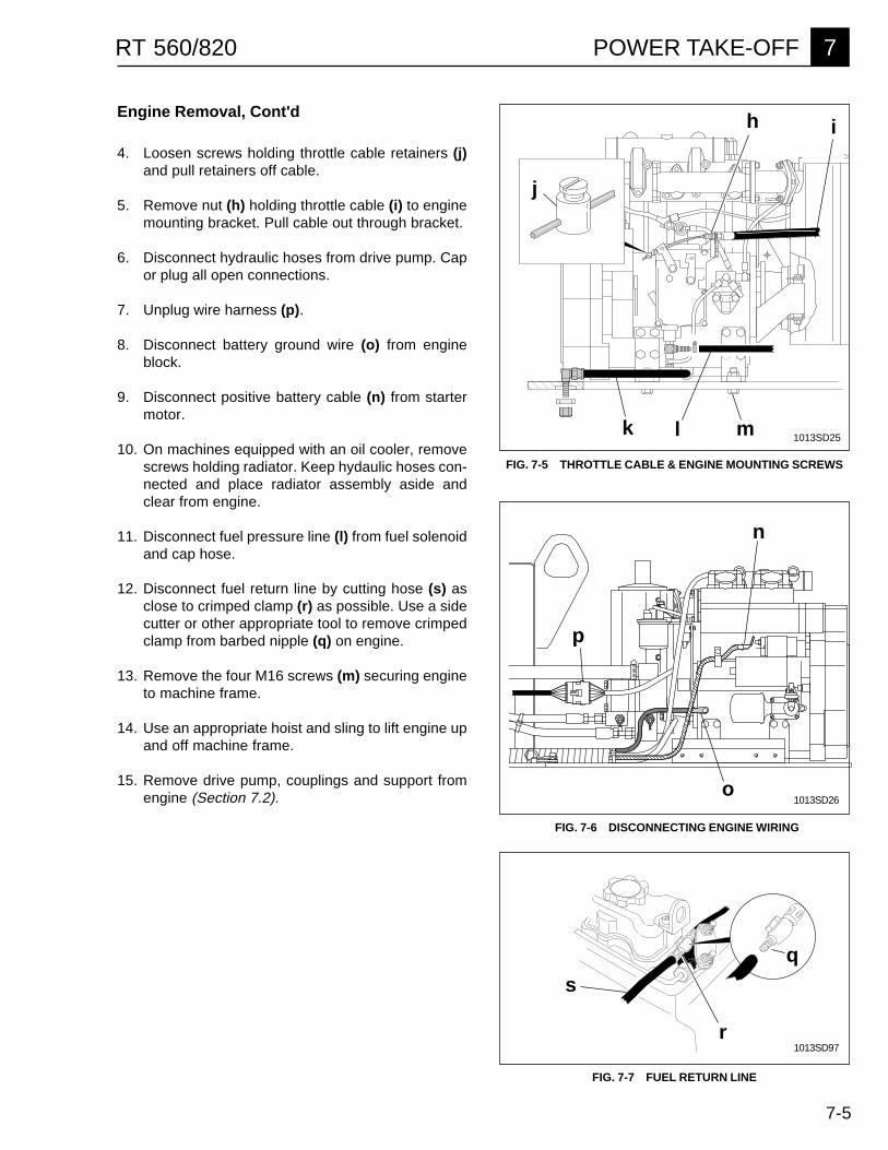
7-5
POWER TAKE-OFF 7RT 560/820
FIG. 7-5 THROTTLE CABLE & ENGINE MOUNTING SCREWS
FIG. 7-7 FUEL RETURN LINE
ih
r
sq
k l m
FIG. 7-6 DISCONNECTING ENGINE WIRING
p
Engine Removal, Cont'd
4. Loosen screws holding throttle cable retainers (j)and pull retainers off cable.
5. Remove nut (h) holding throttle cable (i) to enginemounting bracket. Pull cable out through bracket.
6. Disconnect hydraulic hoses from drive pump. Capor plug all open connections.
7. Unplug wire harness (p).
8. Disconnect battery ground wire (o) from engineblock.
9. Disconnect positive battery cable (n) from startermotor.
10. On machines equipped with an oil cooler, removescrews holding radiator. Keep hydaulic hoses con-nected and place radiator assembly aside andclear from engine.
11. Disconnect fuel pressure line (l) from fuel solenoidand cap hose.
12. Disconnect fuel return line by cutting hose (s) asclose to crimped clamp (r) as possible. Use a sidecutter or other appropriate tool to remove crimpedclamp from barbed nipple (q) on engine.
13. Remove the four M16 screws (m) securing engineto machine frame.
14. Use an appropriate hoist and sling to lift engine upand off machine frame.
15. Remove drive pump, couplings and support fromengine (Section 7.2).
1013SD25
o1013SD26
1013SD97
n
j

7-6
7 POWER TAKE-OFF RT 560/820
Installation:
Replacement engines come equipped with a new volt-age regulator and pump coupling. They do not includethe exhaust system, wiring harness or engine relays.Remove these items from existing engine assembly foruse on new engine.
1. If new engine comes equipped with a wiring har-ness, this harness should be removed.
2. Fasten engine restart module (a), glow plug relay(b) and starter relay (c) on mounting plate andinstall assembly to engine.
3. Remove end cover from exhaust manifold and in-stall exhaust system.
4. The engine comes supplied with one of two voltageregulators (d or e). See Figure 7-9. Spade connec-tions are different between regulators.
If the wiring harness from the old engine is beingused on the new engine, check that the spadeconnections on new regulator fit connector on har-ness. If they don't, pull wires from connector andinstall them in the new connector supplied with theregulator. It will be necessary to remove some ofthe existing terminals from the wires and crimp onones that will connect to the regulator.
To install a new engine harness, crimp terminals onthe three open wires for the voltage regulator. Alsoslide rubber boot for oil pressure switch over whitewire and crimp terminal on.
Connect harness following diagram in Fig. 7-9.
5. Install engine assembly on frame.
6. Install throttle cable. Make sure cable is pushed allthe way in at handle . Insert cable through bracketand secure with nut. Adjust retainers on cable endso machine runs at specified RPM at full throttlecontrol. See section 2.1 engine specification table.
7. Attach low pressure fuel hose to hose fitting oninjector using a hose clamp.
8. Install pump coupling and pump (Section 7.2).
ab
c
FIG. 7-8 ENGINE RELAYS
1013SD35
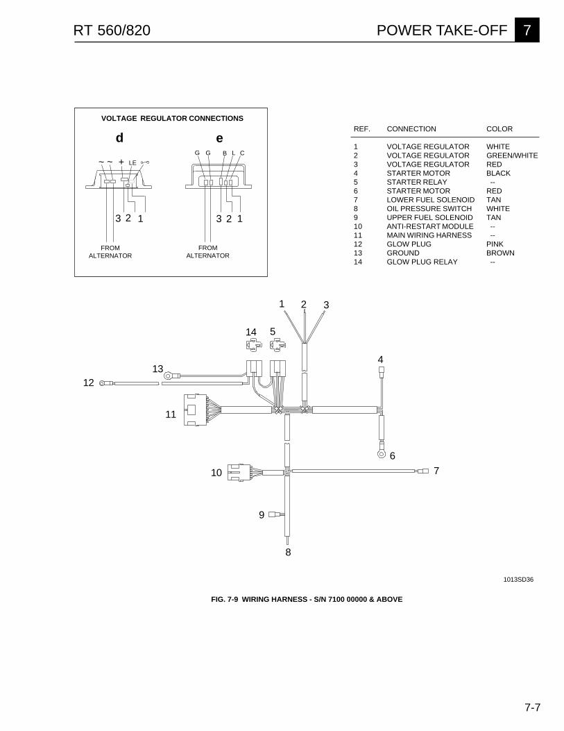
7-7
POWER TAKE-OFF 7RT 560/820
11
123 123
REF. CONNECTION COLOR
1 VOLTAGE REGULATOR WHITE2 VOLTAGE REGULATOR GREEN/WHITE3 VOLTAGE REGULATOR RED4 STARTER MOTOR BLACK5 STARTER RELAY --6 STARTER MOTOR RED7 LOWER FUEL SOLENOID TAN8 OIL PRESSURE SWITCH WHITE9 UPPER FUEL SOLENOID TAN10 ANTI-RESTART MODULE --11 MAIN WIRING HARNESS --12 GLOW PLUG PINK13 GROUND BROWN14 GLOW PLUG RELAY --
FIG. 7-9 WIRING HARNESS - S/N 7100 00000 & ABOVE
1013SD36
CLBGG
LE+~ ~
4
10 7
6
FROMALTERNATOR
ed
VOLTAGE REGULATOR CONNECTIONS
14 5
1213
8
9
2 31
FROMALTERNATOR

7-8
7 POWER TAKE-OFF RT 560/820
NOTES

8-1
RT 560/820 ELECTRICAL SYSTEM 8
UNIT 8
Electrical System
8.1 Introduction ............................................................................................ 8-18.2 Troubleshooting ..................................................................................... 8-18.3 Cord Operated System (S/N 6800 00000 & Below) ..................................... 8-28.4 Infra-red Operated System (S/N 6800 00000 & Below) ............................... 8-38.5 Infra-red & Cord Operated System (S/N 7100 00000 & Above) ................. 8-4
Wiring Schematics - S/N 6800 00000 & Below8.6 Cord Operated Control Box ................................................................... 8-58.7 Infra-red Transmitter .............................................................................. 8-68.8 Cord Operated System .......................................................................... 8-78.9 Infra-red & Cord Operated System ........................................................ 8-8
Wiring Schematics - S/N 7100 00000 & Above8.10 Cord Operated Control Box ................................................................... 8-98.11 Infra-red Transmitter ............................................................................ 8-108.12 Machine Wiring .................................................................................... 8-118.13 Engine Wiring ...................................................................................... 8-12
8.1 Introduction
This unit provides a basic overview of the electricalsystems used on the RT Rollers and does not offerdetailed troubleshooting procedures. Schematics andwiring diagrams are included in this unit for individualsalready familiar with the operation of the electricalsystem and its components. Three basic electricalsystems are in use and differ somewhat in their meth-od of operation and components used. They are de-scribed in Sections 8.3, 8.4 & 8.5.
Two systems utilize digital electronics to receive andinterpret signals from the operator's control box andtransmitter. The third system uses conventional DCcircuitry.
When troubleshooting the electrical system check forthe most common causes of problems first, whichinclude:
1. Loose or broken connections.2. Low battery charge.3. Water damage or excessive moisture.4. Poor ground connection.5. Faulty switches and solenoids.6. Wrong channel selected.
8.2 Troubleshooting
For machines S/N 6800 00000 & below refer toWACKER manual:
Electrical Systems Troubleshooting - P/N 83294
This manual identifies the location and function of allelectrical system components. It provides detailedtroubleshooting procedures for both the cord operatedand infra-red operated systems used on these ma-chines.
For machines S/N 7100 00000 & above consultWACKER Corporation Service Department for assis-tance.
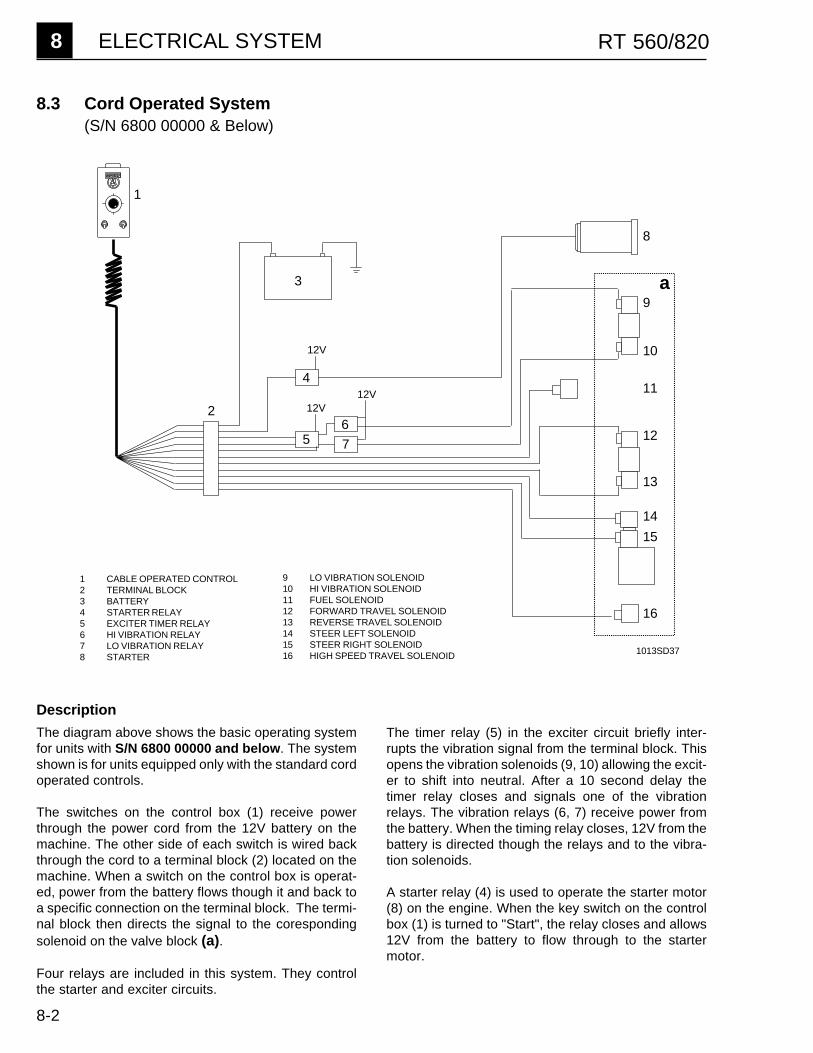
8 ELECTRICAL SYSTEM RT 560/820
8-2
8.3 Cord Operated System(S/N 6800 00000 & Below)
1
1 CABLE OPERATED CONTROL2 TERMINAL BLOCK3 BATTERY4 STARTER RELAY5 EXCITER TIMER RELAY6 HI VIBRATION RELAY7 LO VIBRATION RELAY8 STARTER
9 LO VIBRATION SOLENOID10 HI VIBRATION SOLENOID11 FUEL SOLENOID12 FORWARD TRAVEL SOLENOID13 REVERSE TRAVEL SOLENOID14 STEER LEFT SOLENOID15 STEER RIGHT SOLENOID16 HIGH SPEED TRAVEL SOLENOID
7
62
9
10
11
12
13
14
15
16
8
4
5
3
12V12V
12V
a
Description
The diagram above shows the basic operating systemfor units with S/N 6800 00000 and below. The systemshown is for units equipped only with the standard cordoperated controls.
The switches on the control box (1) receive powerthrough the power cord from the 12V battery on themachine. The other side of each switch is wired backthrough the cord to a terminal block (2) located on themachine. When a switch on the control box is operat-ed, power from the battery flows though it and back toa specific connection on the terminal block. The termi-nal block then directs the signal to the corespondingsolenoid on the valve block (a).
Four relays are included in this system. They controlthe starter and exciter circuits.
1013SD37
The timer relay (5) in the exciter circuit briefly inter-rupts the vibration signal from the terminal block. Thisopens the vibration solenoids (9, 10) allowing the excit-er to shift into neutral. After a 10 second delay thetimer relay closes and signals one of the vibrationrelays. The vibration relays (6, 7) receive power fromthe battery. When the timing relay closes, 12V from thebattery is directed though the relays and to the vibra-tion solenoids.
A starter relay (4) is used to operate the starter motor(8) on the engine. When the key switch on the controlbox (1) is turned to "Start", the relay closes and allows12V from the battery to flow through to the startermotor.

8-3
RT 560/820 ELECTRICAL SYSTEM 8
15 STEER RIGHT SOLENOID16 HIGH SPEED TRAVEL SOLENOID17 CHARGING ADAPTER18 BATTERY PACK19 CHANNEL SWITCH20 INFRA-RED TRANSMITTER21 RECEIVING EYE22 CHANNEL SWITCH23 AMPLIFIER/RECEIVER24 REMOTE CONTROL SWITCH25 ELECTRONIC RELAY26 REMOTE INTERFACE27 REMOTE CONTROL LIGHT
8.4 Infra-red Operated System(S/N 6800 00000 & Below)
Description
The addition of the optional infra-red operating systemto the standard cord operated system on machinesS/N 6800 00000 & below allows machines to operatethrough either the cord connected control box or theinfra-red transmitter. A control switch (24) allows theoperator to select between either system.
Basic operation remains the same as the cord controlsystem described on the previous page except for theaddition of the infra-red interface (26) and other infra-red system components.
In the infra-red system a transmitter (20) is used tosend infra-red signals to a receiving eye (21) on the
21
1
17
18 1920
1 CABLE OPERATED CONTROL2 TERMINAL BLOCK3 BATTERY4 STARTER RELAY5 EXCITER TIMER RELAY6 HI VIBRATION RELAY7 LO VIBRATION RELAY8 STARTER9 LO VIBRATION SOLENOID10 HI VIBRATION SOLENOID11 FUEL SOLENOID12 FORWARD TRAVEL SOLENOID13 REVERSE TRAVEL SOLENOID14 STEER LEFT SOLENOID
1013SD38
2
24
4
5 67
25 26
8
9
10
11
12
13
1415
27
16
3
22
23
machine. The receiving eye transforms the signal to adigital code which is then sent to the receiver module(23). The receiver amplifies and decodes the signalsending it to an electronic relay (25) which is connect-ed to the machine battery. If the receiver signals therelay to close, power from the battery is directed to thecorresponding output and to the remote interface (26)where it is directed to the solenoids. The timer (5) andvibration relays (6, 7) are not used when operating theinfra-red control system. The timing circuit is integrat-ed with the electronic relay.
The remote interface (26) acts as a junction box forboth the cable operated and infra-red systems.

8 ELECTRICAL SYSTEM RT 560/820
8-4
12V
8.5 Infra-red & Cord Operated System(S/N 7100 00000 & Above)
1 CABLE OPERATED CONTROL2 CHANNEL SWITCH3 CONNECTOR4 CHARGING ADAPTER5 BATTERY PACK6 INFRA-RED TRANSMITTER7 RECEIVING EYE8 ELECTRONIC CONTROL
MODULE9 SYSTEM ON SWITCH10 INDICATOR LIGHT11 BRAKE SOLENOID12 STARTER RELAY13 STARTER14 LO VIBRATION SOLENOID15 HI VIBRATION SOLENOID16 HIGH SPEEDSOLENOID17 FORWARD TRAVEL SOLENOID18 REVERSE TRAVEL SOLENOID19 STEER LEFT SOLENOID20 STEER RIGHT SOLENOID21 FUEL SOLENOID22 BATTERY
1013SD39
21
3
13
2
4
2561
7
8 2
11
10
14
15
16
17
18
229
1920
a
12
Description
The electrical system used on machines S/N7100 00000 & above uses a common electronic con-trol module (8) for both the cord and infra-red operatingsystems.This differs from the two previous versions(Sections 8.3 & 8.4) which used electronic modules foronly the infra-red system. Because of this commonelectronic interface the infra-red interface used on ear-lier machines (Section 8.4) is no longer used.
The electronic control module combines the functionsof the amplifier/receiver and relay modules used on theearlier systems. A "system on" switch (9) suppliespower from the machine battery (22) to the module (8).The module then transmits power to both the cableoperated control box (1) and the receiving eye (7). Theinfra-red transmitter is powered by a rechargeable ni-cad battery (5).
Both the cable operated and infra-red operated sys-tems plug in to a common connector and transmit adigitally coded signal to the electronic control module(8). The module amplifies and decodes the signal andsupplies 12V to the corresponding solenoids on thevalve block (a).
The 10 second time delay, when switching vibrationmodes, is built in as part of the control module. As aresult, the timer and vibration relays used on the previ-ous electrical systems are no longer required.
A starter relay (12) is used to operate the starter motor.The starter relay opens or closes in response to thesignal from the electronic control module.

8-5
RT 560/820 ELECTRICAL SYSTEM 8
8.6 Schematic - Cord Operated Control Box(S/N 6800 00000 & Below)
1
2
3
4
5
6
7
8
9
10
11
12
HITVL
ST
RUN
LOVIB
HIVIB
FWD
REV
RT
LT
15 AMP
30
50
15
1
2
3
1
3
12
3
1 3
1 3
1 3
IGN
VIB
JSK
TR
TB
RR
R
R
R
R
W
B
T
Y
Pr
Gr
YOr
Or
L
P
P
Y
TOTERMINAL BLOCK
ON MACHINE(SECTIONS 8.8 & 8.9)
Wire Colors
B - BlackG - GreenL - BlueP - PinkR - RedT - Tan
IGN Ignition SwitchJSK JoystickTB Terminal BlockVIB Vibration SwitchTR Travel Switch
W- WhiteY - YellowBr - BrownGr - GrayOr - OrangePr - Purple
1002SD57

8 ELECTRICAL SYSTEM RT 560/820
8-6
1022SD52
8.7 Schematic - Infra-red Transmitter(S/N 6800 00000 & Below)
��
�
�
�
A
BC
REV.
FWDRT LT
30
1550
RED
RED
RED
RED
POS
NEG
TOP BOTTOM
1 2 3
4
5
8
7
6
1 EXCITER SWITCH2 JOYSTICK3 TRANSMITTER COVER4 BATTERY PACK5 POWER ADAPTER PACKS6 KEY SWITCH7 GREEN LED8 RED LED
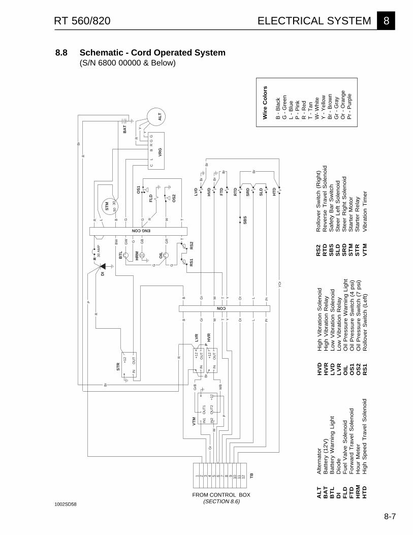
8-7
RT 560/820 ELECTRICAL SYSTEM 8
8.8 Schematic - Cord Operated System(S/N 6800 00000 & Below)
Wir
e C
olo
rs
B -
Bla
ckG
- G
reen
L -
Blu
eP
- P
ink
R -
Red
T -
Tan
W-
Whi
teY
- Y
ello
wB
r -
Bro
wn
Gr
- G
ray
Or
- O
rang
eP
r -
Pur
ple
FROM CONTROL BOX(SECTION 8.6)
ST
R
HV
R
LV
RV
TM
DI
BT
L
HR
M
OIL
RS
1R
S2
OS
2
OS
1
SB
S
FL
D
ST
M
VR
GA
LT
HV
D
LV
D
FT
D
RT
D
SR
D
SL
D
HT
D
BA
T
IN1
IN2
OU
T1
OU
T2
+12
INO
UT
+12
INO
UT
+12
INO
UT
+12
CL
BR
GG
30 A
MP
5030
TB
1 2 3 4 5 6 7 8 9 10 11 12
ENG CON
CON
P
PrB Gr
Gr
W T Y Or L
LOrYTW
G G
GR
GB
GW
BW G
T
R L W TRGGB
R
Gr
W
PW
B
GrB
Br
Br
Br
Br
RY
Y
Pr
R
Br
YO
r
P
Br
Br
B
RB
r
R
RS
2R
ollo
ver
Sw
itch
(R
igh
t)R
TD
Re
vers
e T
rave
l S
ole
no
idS
BS
Sa
fety
Ba
r S
witc
hS
LD
Ste
er
Le
ft S
ole
no
idS
RD
Ste
er
Rig
ht
So
len
oid
ST
MS
tart
er
Mo
tor
ST
RS
tart
er
Re
lay
VT
MV
ibra
tion
Tim
er
HV
DH
igh
Vib
ratio
n S
ole
no
idH
VR
Hig
h V
ibra
tion
Re
lay
LV
DL
ow
Vib
ratio
n S
ole
no
idL
VR
Lo
w V
ibra
tion
Re
lay
OIL
Oil
Pre
ssu
re W
arn
ing
Lig
ht
OS
1O
il P
ress
ure
Sw
itch
(4
psi
)O
S2
Oil
Pre
ssu
re S
witc
h (
7 p
si)
RS
1R
ollo
ver
Sw
itch
(L
eft
)
AL
TA
ltern
ato
rB
AT
Ba
tte
ry (
12
V)
BT
LB
att
ery
Wa
rnin
g L
igh
tD
ID
iod
eF
LD
Fu
el
Va
lve
So
len
oid
FT
DF
orw
ard
Tra
vel
So
len
oid
HR
MH
ou
r M
ete
rH
TD
Hig
h S
pe
ed
Tra
vel
So
len
oid
1002SD58

8 ELECTRICAL SYSTEM RT 560/820
8-8
8.9 Schematic - Infra-red & Cord Operated System(S/N 6800 00000 & Below)
AL
TA
ltern
ator
AM
PA
mpl
ifier
BA
TB
atte
ry (
12V
)B
TL
Bat
tery
War
ning
Lig
htC
ON
Con
nect
orD
ID
iode
EY
EIn
fra-
red
Sen
sing
Eye
FL
DF
uel V
alve
Sol
enoi
dF
TD
For
war
d T
rave
l Sol
enoi
dH
RM
Hou
r M
eter
HT
DH
igh
Spe
ed T
rave
l Sol
enoi
dH
VD
Hig
h V
ibra
tion
Sol
enoi
dH
VR
Hig
h V
ibra
tion
Rel
ayIR
IIn
fra-
red
Inte
rfac
eIR
LIn
fra-
red
Indi
cato
r Li
ght
IRS
Infr
a-R
ed S
witc
h
Br
Br
R
30 A
MP
ST
R
HV
R
LV
RV
TM
DI
RS
1R
S2
OS
2
OS
1
SB
S
FL
D
ST
M
VR
GA
LT
HV
D
LV
D
FT
D
RT
D
SR
D
SL
D
HT
D
BA
T
IN1
IN2
OU
T1
OU
T2
+12
INO
UT
+12
INO
UT
+12
INO
UT
+12
CL
BR
GG
5030
TB
1 2 3 4 5 6 7 8 9 10 11 12
CON
R
W
Pr
P
B Gr
W
TY
Or
L
LOrYW
TTTGB
R
Gr
W
P
WB
GrB
RY
Y
Pr
R
R
BT
L
HR
M
OIL
ENG CON
GR
GB
BW GGW
Br
Br
Br
Br
Br
P
RR
L G Br
Pr
LO
rY
TW
Gr
B
Pr
LO
rY
TW
Gr
B
BG
rW
TY
Or
LP
r
Br
WR
Br
G
Gr
YO
r
WR
L
IRI
EY
EA
MP
IRL
IRS
LEFT
RIGHT
REV
FWD
FUEL
HI VIB
LO VIB
START
- GND
D0 CORD
+ IR
D1 START
D2 LO VIB
D3 HI VIB
D4 FUEL
D5 FWD
D6 REV
D7 RIGHT
D8 LEFT
D9 LIGHT
G G
FROM CONTROL BOX(SECTION 8.6) 1002SD66
LV
DLo
w V
ibra
tion
Sol
enoi
dL
VR
Low
Vib
ratio
n R
elay
OIL
Oil
Pre
ssur
e W
arni
ng L
ight
OS
1O
il P
ress
ure
Sw
itch
(4 p
si)
OS
2O
il P
ress
ure
Sw
itch
(7 p
si)
RS
1R
ollo
ver
Sw
itch
(Lef
t)R
S2
Rol
love
r S
witc
h (R
ight
)R
TD
Rev
erse
Tra
vel S
olen
oid
SB
SS
afet
y B
ar S
witc
hS
LD
Ste
er L
eft S
olen
oid
SR
DS
teer
Rig
ht S
olen
oid
ST
MS
tart
er M
otor
ST
RS
tart
er R
elay
VR
GV
olta
ge R
egul
ator
VT
MV
ibra
tion
Tim
er
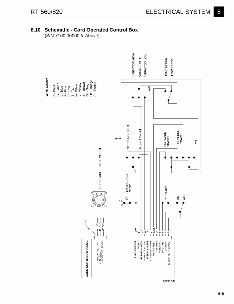
8-9
RT 560/820 ELECTRICAL SYSTEM 8
8.10 Schematic - Cord Operated Control Box(S/N 7100 00000 & Above)
Wir
e C
olo
rs
B -
Bla
ckG
- G
reen
L -
Blu
eP
- P
ink
R -
Red
T -
Tan
W-
Whi
teY
- Y
ello
wB
r -
Bro
wn
Gr
- G
ray
Or
- O
rang
eP
r -
Pur
ple
1013SD40
TT
HIG
H S
PE
ED
LOW
SP
EE
D
VIB
RA
TIO
N H
IGH
VIB
RA
TIO
N O
FF
VIB
RA
TIO
N L
OW
W/B
ST
EE
RIN
G R
IGH
T
ST
EE
RIN
G L
EF
T
T/B
FO
RW
AR
DT
RA
VE
L
RE
VE
RS
ET
RA
VE
L
RE
CE
PT
AC
LE-P
AN
EL
MO
UN
T
NE
GA
TIV
E, G
ND
S
IGN
AL
+ P
OS
ITIV
E, 1
2VD
C
EM
ER
GE
NC
YS
TO
P
ST
AR
T
OF
F
ON
CO
RD
CO
NT
RO
L M
OD
UL
E
5 V
DC
OU
TP
UT
BR
AK
EV
IBR
AT
ION
HIG
HV
IBR
AT
ION
LO
WS
TE
ER
ING
LE
FT
ST
EE
RIN
G R
IGH
TH
IGH
SP
EE
DR
EV
ER
SE
FO
RW
AR
D50
(ST
AR
T)
15 (
RU
N)
30 (
BA
TT
ER
Y 1
2VD
C)
G
"A"
R/W
T Gr
W Pr
L Y/O
rO
rY B P R
G
"A"
B
"B"
W "
C"
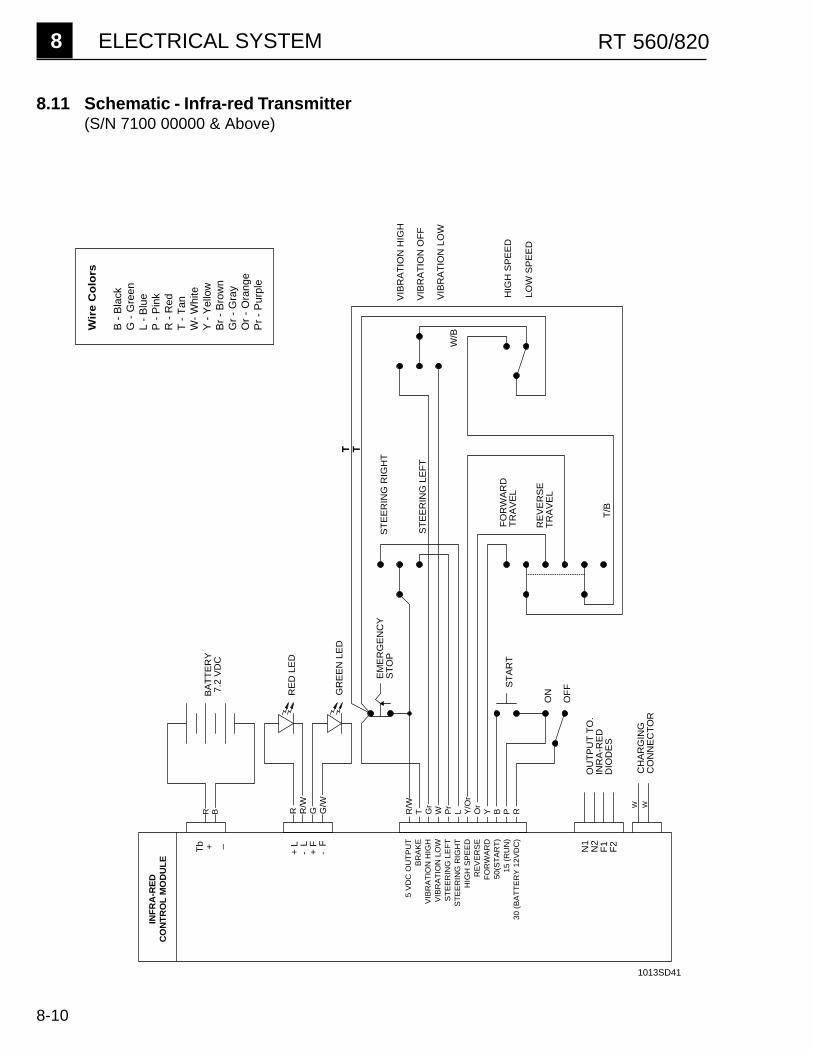
8 ELECTRICAL SYSTEM RT 560/820
8-10
8.11 Schematic - Infra-red Transmitter(S/N 7100 00000 & Above)
HIG
H S
PE
ED
LOW
SP
EE
D
VIB
RA
TIO
N H
IGH
VIB
RA
TIO
N O
FF
VIB
RA
TIO
N L
OW
ST
EE
RIN
G R
IGH
T
ST
EE
RIN
G L
EF
T
RE
D L
ED
GR
EE
N L
ED
ST
AR
T
OF
F
ONB
AT
TE
RY
7.2
VD
C
T/B
WW
T T
W/B
5 V
DC
OU
TP
UT
BR
AK
EV
IBR
AT
ION
HIG
HV
IBR
AT
ION
LO
WS
TE
ER
ING
LE
FT
ST
EE
RIN
G R
IGH
TH
IGH
SP
EE
DR
EV
ER
SE
FO
RW
AR
D50
(ST
AR
T)
15 (
RU
N)
30 (
BA
TT
ER
Y 1
2VD
C)
EM
ER
GE
NC
YS
TO
P
OU
TP
UT
TO
.IN
RA
-RE
DD
IOD
ES
+ L
- L
+ F
- F N1
N2
F1
F2
CH
AR
GIN
GC
ON
NE
CT
OR
FO
RW
AR
DT
RA
VE
L
RE
VE
RS
ET
RA
VE
L
Tb + _
INF
RA
-RE
D
CO
NT
RO
L M
OD
UL
E
R R/W
G G/W
R B R/W
T Gr
W Pr
L Y/O
rO
rY B P R
Wir
e C
olo
rs
B -
Bla
ckG
- G
reen
L -
Blu
eP
- P
ink
R -
Red
T -
Tan
W-
Whi
teY
- Y
ello
wB
r -
Bro
wn
Gr
- G
ray
Or
- O
rang
eP
r -
Pur
ple
1013SD41
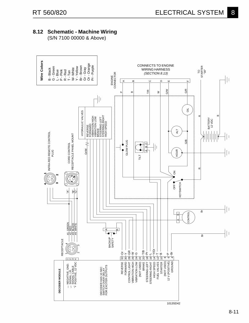
8-11
RT 560/820 ELECTRICAL SYSTEM 8
EN
GIN
EC
ON
NE
CT
OR
DE
CO
DE
R M
OD
UL
E
GLO
W P
LUG
OF
FO
N
G/B
R
TIL
T
CO
NT
RO
L
HO
UR
ALT
OIL
CO
RD
CO
NT
RO
L
HY
DR
AU
LIC
VA
LVE
S
KE
YS
WIT
CH
B
G/R
RB
r
AB
Br
RE
VE
RS
E
32F
OR
WA
RD
30
CO
NT
RO
L LI
GH
T
28V
IBR
AT
ION
-HIG
H
26V
IBR
AT
ION
-LO
W
24(N
OT
US
ED
) 2
2B
RA
KE
20
ST
EE
RIN
G-L
EF
T
18S
TE
ER
ING
-RIG
HT
16
HIG
H S
PE
ED
14
FU
EL
VA
LVE
S
12S
TA
RT
ER
10
(NO
T U
SE
D)
8
12 V
(P
OS
ITIV
E)
6
GR
OU
ND
4
DE
CO
DE
R H
AS
10
SE
CS
WIT
CH
OV
ER
DE
LAY
FO
R E
XC
ITE
R O
UT
PU
TS
N
EG
AT
IVE
, GN
D.
S
IGN
AL,
I.R
.
SIG
NA
L C
AB
LE+
PO
SIT
IVE
, 12
VD
C
RE
CE
PT
AC
LE
PLU
GIN
FR
A-R
ED
RE
MO
TE
CO
NT
RO
L.
RE
CE
PT
AC
LE P
AN
EL
MO
UN
T
RE
VE
RS
EF
OR
WA
RD
VIB
RA
TIO
N H
IGH
VIB
RA
TIO
N L
OW
BR
AK
ES
TE
ER
ING
LE
FT
ST
EE
RIN
G R
IGH
TH
IGH
SP
EE
D
Or/
W
A B C D E F
P B T/R W G/W
A
B C
BA
CK
UP
SA
FE
TY
BA
TT
ER
Y12
VD
C
TO
ST
AR
TE
R"3
0"
1 23
1
34
ABC
1 2 3 4
#1 G
RE
EN
#2 R
ED
#3 B
LAC
K#4
WH
ITE
4"A
"
"B"
"C"
2
A B
Or
Y GR
W G T/B
Pr
L Y/O
rT B P B
r
8.12 Schematic - Machine Wiring(S/N 7100 00000 & Above)
CONNECTS TO ENGINEWIRING HARNESS
(SECTION 8.13)
Wir
e C
olo
rs
B -
Bla
ckG
- G
reen
L -
Blu
eP
- P
ink
R -
Red
T -
Tan
W-
Whi
teY
- Y
ello
wB
r -
Bro
wn
Gr
- G
ray
Or
- O
rang
eP
r -
Pur
ple
1013SD42
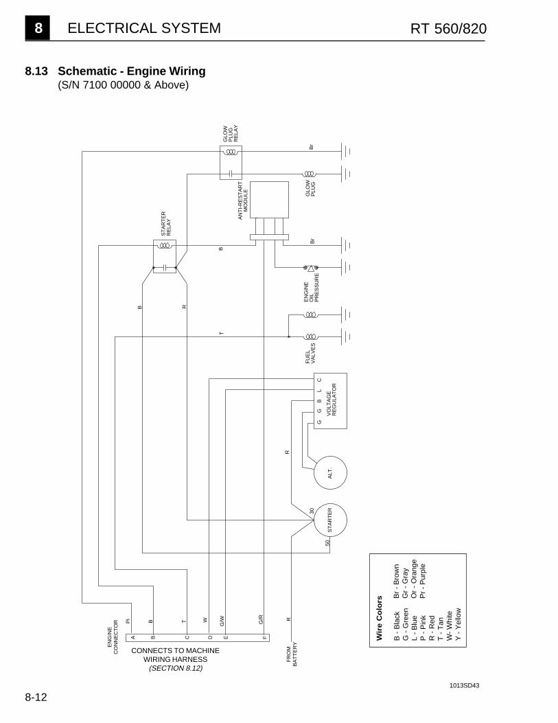
8 ELECTRICAL SYSTEM RT 560/820
8-12
8.13 Schematic - Engine Wiring(S/N 7100 00000 & Above)
CONNECTS TO MACHINEWIRING HARNESS
(SECTION 8.12)
1013SD43
Wir
e C
olo
rs
B -
Bla
ckG
- G
reen
L -
Blu
eP
- P
ink
R -
Red
T -
Tan
W-
Whi
teY
- Y
ello
w
Br
- B
row
nG
r -
Gra
yO
r -
Ora
nge
Pr
- P
urpl
e
Pi
B T W
G/W G/R R
ST
AR
TE
RA
LT.
G
G
B
L
C30
50
R
B
T
R
B
Br
Br
EN
GIN
EO
ILP
RE
SS
UR
E
GLO
WP
LUG
RE
LAY
ST
AR
TE
RR
ELA
Y AN
TI-
RE
ST
AR
TM
OD
ULE
VO
LTA
GE
RE
GU
LAT
OR
FU
EL
VA
LVE
S
A B C D E F
GLO
WP
LUG
EN
GIN
EC
ON
NE
CT
OR
FR
OM
B
AT
TE
RY
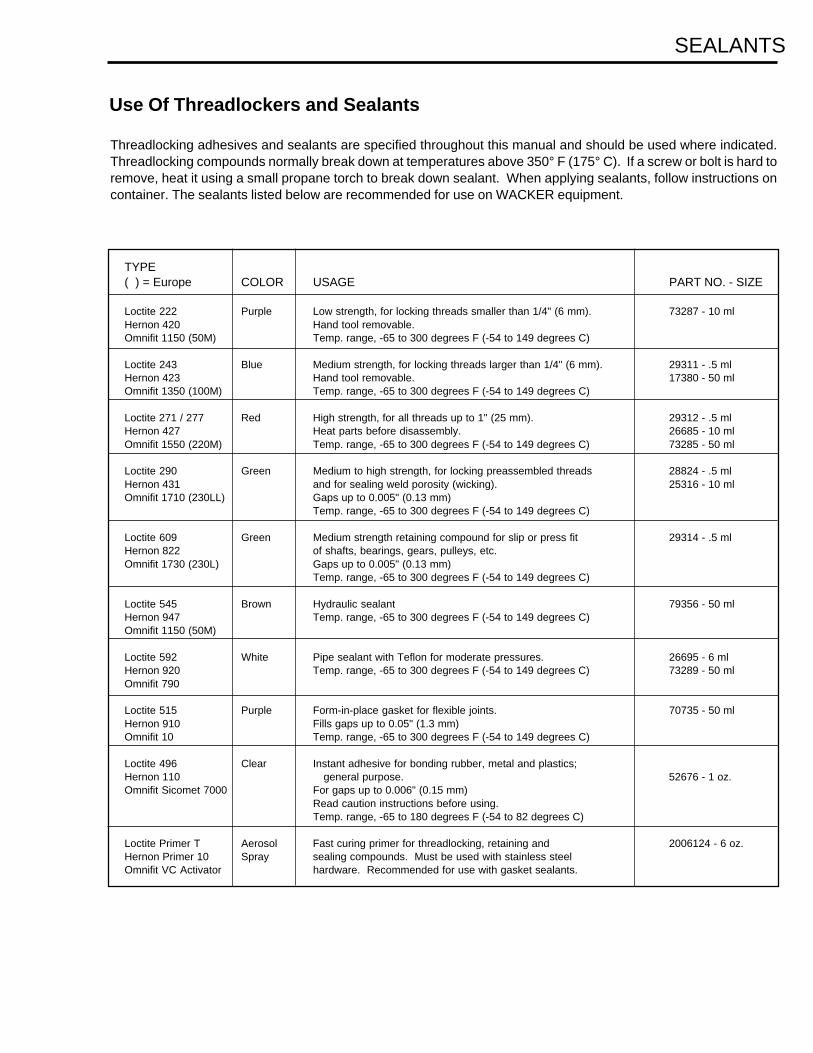
Use Of Threadlockers and Sealants
Threadlocking adhesives and sealants are specified throughout this manual and should be used where indicated.Threadlocking compounds normally break down at temperatures above 350° F (175° C). If a screw or bolt is hard toremove, heat it using a small propane torch to break down sealant. When applying sealants, follow instructions oncontainer. The sealants listed below are recommended for use on WACKER equipment.
SEALANTS
TYPE( ) = Europe COLOR USAGE PART NO. - SIZE
Loctite 222 Purple Low strength, for locking threads smaller than 1/4" (6 mm). 73287 - 10 mlHernon 420 Hand tool removable.Omnifit 1150 (50M) Temp. range, -65 to 300 degrees F (-54 to 149 degrees C)
Loctite 243 Blue Medium strength, for locking threads larger than 1/4" (6 mm). 29311 - .5 mlHernon 423 Hand tool removable. 17380 - 50 mlOmnifit 1350 (100M) Temp. range, -65 to 300 degrees F (-54 to 149 degrees C)
Loctite 271 / 277 Red High strength, for all threads up to 1" (25 mm). 29312 - .5 mlHernon 427 Heat parts before disassembly. 26685 - 10 mlOmnifit 1550 (220M) Temp. range, -65 to 300 degrees F (-54 to 149 degrees C) 73285 - 50 ml
Loctite 290 Green Medium to high strength, for locking preassembled threads 28824 - .5 mlHernon 431 and for sealing weld porosity (wicking). 25316 - 10 mlOmnifit 1710 (230LL) Gaps up to 0.005" (0.13 mm)
Temp. range, -65 to 300 degrees F (-54 to 149 degrees C)
Loctite 609 Green Medium strength retaining compound for slip or press fit 29314 - .5 mlHernon 822 of shafts, bearings, gears, pulleys, etc.Omnifit 1730 (230L) Gaps up to 0.005" (0.13 mm)
Temp. range, -65 to 300 degrees F (-54 to 149 degrees C)
Loctite 545 Brown Hydraulic sealant 79356 - 50 mlHernon 947 Temp. range, -65 to 300 degrees F (-54 to 149 degrees C)Omnifit 1150 (50M)
Loctite 592 White Pipe sealant with Teflon for moderate pressures. 26695 - 6 mlHernon 920 Temp. range, -65 to 300 degrees F (-54 to 149 degrees C) 73289 - 50 mlOmnifit 790
Loctite 515 Purple Form-in-place gasket for flexible joints. 70735 - 50 mlHernon 910 Fills gaps up to 0.05" (1.3 mm)Omnifit 10 Temp. range, -65 to 300 degrees F (-54 to 149 degrees C)
Loctite 496 Clear Instant adhesive for bonding rubber, metal and plastics;Hernon 110 general purpose. 52676 - 1 oz.Omnifit Sicomet 7000 For gaps up to 0.006" (0.15 mm)
Read caution instructions before using.Temp. range, -65 to 180 degrees F (-54 to 82 degrees C)
Loctite Primer T Aerosol Fast curing primer for threadlocking, retaining and 2006124 - 6 oz.Hernon Primer 10 Spray sealing compounds. Must be used with stainless steelOmnifit VC Activator hardware. Recommended for use with gasket sealants.

Size Ft.Lb. Nm Ft.Lb. Nm Ft.Lbs. Nm Inch Metric Inch Metric
No.4 *6 0.7 *14 1.0 *12 1.4 1/4 5.5 3/32 -
No.6 *12 1.4 *17 1.9 *21 2.4 5/16 8 7/64 -
No.8 *22 2.5 *31 3.5 *42 4.7 11/32 9 9/64 -
No.10 *32 3.6 *45 5.1 *60 6.8 3/8 - 5/32 -
1/4 6 8.1 9 12 12 16 7/16 - 3/32 -
5/16 13 18 19 26 24 33 1/2 13 1/4 -
3/8 23 31 33 45 43 58 9/16 - 5/16 -
7/16 37 50 52 71 69 94 5/8 16 3/8 -
1/2 57 77 80 109 105 142 3/4 19 3/8 -
9/16 82 111 115 156 158 214 13/16 - - -
5/8 112 152 159 216 195 265 15/16 24 1/2 -
3/4 200 271 282 383 353 479 1-1/8 - 5/8 -
1 Ft.Lb. = 1.357 Nm 1 Inch = 25.4 mm* = In.Lb.
Metric Fasteners (DIN)
Inch Fasteners (SAE)
Size Ft.Lb. Nm Ft.Lb. Nm Ft.Lbs. Nm Inch Metric Inch Metric
M3 *11 1.2 *14 1.6 *19 2.1 7/32 5.5 - 2.5
M4 *26 2.9 *36 4.1 *43 4.9 9/32 7 - 3
M5 *53 6.0 6 8.5 7 10 5/16 8 - 4
M6 7 10 10 14 13 17 - 10 - 5
M8 18 25 26 35 30 41 1/2 13 - 6
M10 36 49 51 69 61 83 11/16 17 - 8
M12 63 86 88 120 107 145 3/4 19 - 10
M14 99 135 140 190 169 230 7/8 22 - 12
M16 155 210 217 295 262 355 15/16 24 - 14
M18 214 290 298 405 357 485 1-1/16 27 - 14
M20 302 410 427 580 508 690 1-1/4 30 - 17
8.8 10.9
TORQUE VALUES (Based on Bolt Size and Hardness) WRENCH SIZE
12.9 12.910.98.8
TORQUE VALUES
SAE 5 SAE 8


Wacker Construction Equipment AG · Preußenstraße 41 · D-80809 München · Tel.: +49-(0)89-354 02 - 0 · Fax: +49 - (0)89-354 02-390Wacker Corporation · P.O. Box 9007 · Menomonee Falls, WI 53052-9007 · Tel. : +1-(1)(262) 255-0500 · Fax: +1-(1)(262) 255-0550 · Tel. : (800) 770-0957Wacker Asia Pacific Operations · Sunley Center, Unit 912, 9/F · 9 Wing Qin Street, Kwai Chung, N.T. · Hong Kong · Tel. + 852 2406 60 32 · Fax: + 852 2406 60 21