RSSI/DoA Based Positioning Systems for Wireless Sensor Network
24
RSSI/DoA Based Positioning Systems for Wireless Sensor Network Stefano Maddio, Alessandro Cidronali and Gianfranco Manes Additional information is available at the end of the chapter http://dx.doi.org/10.5772/50380 1. Introduction The problem of localization of a mobile device has interested researchers since the beginning of XX century, as testified by the experiments of Bellini and Tosi [20]. This challenging research topic has gained even more momentum in recent years, particularly with the introduction of modern ICT technologies such as Wireless Sensor Network (WSN). A Wireless Sensor Network is an infrastructure comprised of a set independent nodes able to sense (measure), process and communicate among themselves and toward a remote sink node which operates as data aggregator and forwards the information to the final user. WSN are already actively employed in unattended and non-invasive activities like prevention of art deterioration [1, 23], agricultural monitoring [18], environment monitoring [17, 22], surveillance application [2, 10]. In most cases, if not in all cases, it is necessary to report the measured data to the position of the observed phenomenon, otherwise the measurement would be meaningless. This means that the sensor nodes have to be aware of their position, and if this information is not known, a localization service must be implemented. The position awareness that comes from this service can boost specific routing operations (adaptability, latency, throughput) with the nodes able to independently determine the best modality to cooperate and communicate the data to the end user by means of a continuous exchange of messages. The objective of a localization system is to assign a positional information to each node of the network, either in the form of a relative position to a known anchor reference of within a coordinate system [7]. A localization procedure can be described as the series of three steps: • Signal observation • Extract of position-related signal parameters • Estimation of location coordinates ©2012 Maddio et al., licensee InTech. This is an open access chapter distributed under the terms of the Creative Commons Attribution License (http://creativecommons.org/licenses/by/3.0), which permits unrestricted use, distribution, and reproduction in any medium, provided the original work is properly cited. Chapter 7
Transcript of RSSI/DoA Based Positioning Systems for Wireless Sensor Network

Chapter 0
RSSI/DoA Based Positioning Systemsfor Wireless Sensor Network
Stefano Maddio, Alessandro Cidronali and Gianfranco Manes
Additional information is available at the end of the chapter
http://dx.doi.org/10.5772/50380
1. Introduction
The problem of localization of a mobile device has interested researchers since the beginningof XX century, as testified by the experiments of Bellini and Tosi [20]. This challenging researchtopic has gained even more momentum in recent years, particularly with the introduction ofmodern ICT technologies such as Wireless Sensor Network (WSN).
A Wireless Sensor Network is an infrastructure comprised of a set independent nodes ableto sense (measure), process and communicate among themselves and toward a remote sinknode which operates as data aggregator and forwards the information to the final user.WSN are already actively employed in unattended and non-invasive activities like preventionof art deterioration [1, 23], agricultural monitoring [18], environment monitoring [17, 22],surveillance application [2, 10]. In most cases, if not in all cases, it is necessary to reportthe measured data to the position of the observed phenomenon, otherwise the measurementwould be meaningless. This means that the sensor nodes have to be aware of their position,and if this information is not known, a localization service must be implemented. The positionawareness that comes from this service can boost specific routing operations (adaptability,latency, throughput) with the nodes able to independently determine the best modality tocooperate and communicate the data to the end user by means of a continuous exchange ofmessages.
The objective of a localization system is to assign a positional information to each node ofthe network, either in the form of a relative position to a known anchor reference of within acoordinate system [7]. A localization procedure can be described as the series of three steps:
• Signal observation
• Extract of position-related signal parameters
• Estimation of location coordinates
©2012 Maddio et al., licensee InTech. This is an open access chapter distributed under the terms of theCreative Commons Attribution License (http://creativecommons.org/licenses/by/3.0), which permitsunrestricted use, distribution, and reproduction in any medium, provided the original work is properlycited.
Chapter 7
2 Will-be-set-by-IN-TECH
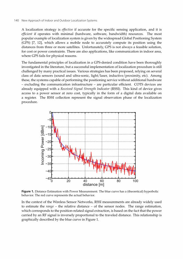
A localization strategy is effective if accurate for the specific sensing application, and it isefficient if operates with minimal (hardware, software, bandwidth) resources. The mostpopular example of localization system is given by the widespread Global Positioning System(GPS) [7, 12], which allows a mobile node to accurately compute its position using thedistances from three or more satellites. Unfortunately, GPS is not always a feasible solution,for cost or power constraints. There are also applications, like communication in indoor area,where GPS fails for physical reasons.
The fundamental principles of localization in a GPS-denied condition have been thoroughlyinvestigated in the literature, but a successful implementation of localization procedure is stillchallenged by many practical issues. Various strategies has been proposed, relying on severalclass of data sensors (sound and ultra-sonic, light/laser, inductive/proximity, etc). Amongthese, the systems capable of performing the positioning service without additional hardware– excluding the communication infrastructure – are particular efficient. COTS devices arealready equipped with a Received Signal Strength Indicator (RSSI). This kind of device givesaccess to a power sensor at zero cost, typically in the form of a digital data available ona register. The RSSI collection represent the signal observation phase of the localizationprocedure.
0 20 40 60 80 100−45
−40
−35
−30
−25
−20
−15
−10
−5
0
distance [m]
Inco
min
g P
ower
[dB
m]
Figure 1. Distance Estimation with Power Measurement. The blue curve has a (theoretical) hyperbolicbehavior. The red curve represents the actual behavior.
In the context of the Wireless Sensor Networks, RSSI measurements are already widely usedto estimate the range – the relative distance – of the sensor nodes. The range estimation,which corresponds to the position-related signal extraction, is based on the fact that the powercarried by an RF signal is inversely proportional to the traveled distance. This relationship isgraphically described by the blue curve in Figure 1.
140 New Approach of Indoor and Outdoor Localization Systems

RSSI/DoA Based Positioning Systems for Wireless Sensor Network 3
When at least three range measurements respect to three reference – non collinear – nodesare available, the estimation of location coordinates is obtained on the basis of trilaterationalgorithms, graphically described in Figure 2(a). The intersection of three circles, eventuallyin the mean square error sense, corresponds to the solution of a non-linear system, a trivialnumeric elaboration.
Unfortunately, traveling radio signals are influenced by the indoor environment, beingstrongly affected by the reflected, refracted and scattered waves (multi-path) and disturbedby other devices communications (interferences). The actual power/distance relationship ismore similar to the red noisy curve of Figure 1. Because of this noisy behavior, the powerestimation is affected by a low accuracy, ultimately leading to a coarse position estimation,as depicted in Figure 2(b). This bad condition can be mitigated if more than three ranges areavailable, which leads to an overdetermined system (multilateration).
(a) Ideal case (b) Real case
Figure 2. Target localization by trilateration algorithm. The position of a node is determined with threerange estimations respect to three reference nodes.
Figure 3. Direction of Arrival estimation with a multi-beam antenna system.
RSSI measurements can also be employed for Direction of Arrival (DoA) estimation. Apositioning system based on DoA information does not rely on actual range measurements,i.e. it is range-free algorithm. The extraction of the signal DoA parameter is based on the
141RSSI/DoA Based Positioning Systems for Wireless Sensor Network

4 Will-be-set-by-IN-TECH
antenna reception with a multi beam system, an antenna capable to radiate N directional beampatterns arranged in a sectorialised manner. The logic is to sense a power vector fromdifferent direction, as explained by Figure 3. Intuitively, if each beam is narrow enough,the antenna operates as a spatial filter, isolating a specific angular region. This estimationprocedure is tolerant to noisy power measurements, because it has a range-free nature, thus itis particularly suitable for the a coarse power meter like RSSI. The critical condition for is theneed of a fast scanning of the available beam, to ensure the same channel condition throughthe N antenna beams. For a DoA based algorithm, the estimation of position coordinatesrelies on the collaboration of at least two nodes operating as beacons, as explained in Figure 4.Each anchor estimates the DoA of the target respect to its relative reference, identifying aline of bearing. The intersection of two lines uniquely identify the target position. As forthe multilateration, the collaboration of three or more anchors can enhance the estimationeffectiveness.
Figure 4. Target localization by DoA intersection. The estimated position does not rely on rangemeasurement.
2. Node design
This section describes a brief summary of the typical hardware of a a sensor node suitable forthe described RSSI/DoA-based localization system. The idea is to use two class of nodes. Themaster node, designed with a system consisting of a transceiver and a micro-controller as thecore intelligence and equipped with the complex radiative system. The slave node, based onanalogous but simplified design and equipped with a simple antenna. The master (anchor)node can be thought as the sink/coordinator, a specialized node, eventually placed by hand,serving as an access point. The slave (target) node, is the independent node, eventually freeto move in the area within the communication range of at least one master node.
Recent advances in RFIC design opened the door to low-cost commercial transceivertechnology. The CC2430 from Texas Instruments is a true System-on-Chip (SoC), an highlyintegrated RF chip built in 0.18 μm CMOS standard technology, with a compact 7×7 mmQLP48 package. CC2430 comes with an excellent transceiver, boosted with 2.4GHz DSSS
142 New Approach of Indoor and Outdoor Localization Systems
RSSI/DoA Based Positioning Systems for Wireless Sensor Network 5
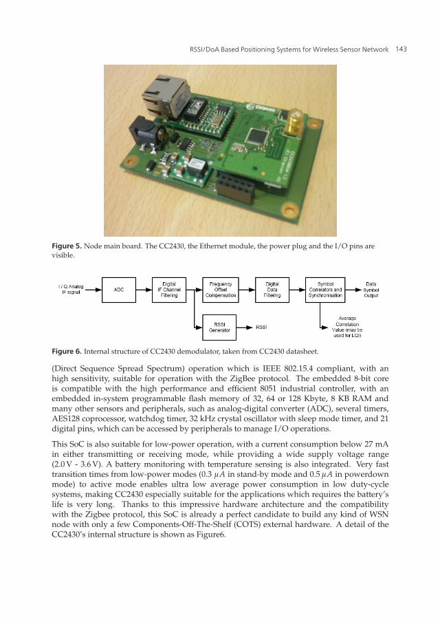
Figure 5. Node main board. The CC2430, the Ethernet module, the power plug and the I/O pins arevisible.
Figure 6. Internal structure of CC2430 demodulator, taken from CC2430 datasheet.
(Direct Sequence Spread Spectrum) operation which is IEEE 802.15.4 compliant, with anhigh sensitivity, suitable for operation with the ZigBee protocol. The embedded 8-bit coreis compatible with the high performance and efficient 8051 industrial controller, with anembedded in-system programmable flash memory of 32, 64 or 128 Kbyte, 8 KB RAM andmany other sensors and peripherals, such as analog-digital converter (ADC), several timers,AES128 coprocessor, watchdog timer, 32 kHz crystal oscillator with sleep mode timer, and 21digital pins, which can be accessed by peripherals to manage I/O operations.
This SoC is also suitable for low-power operation, with a current consumption below 27 mAin either transmitting or receiving mode, while providing a wide supply voltage range(2.0 V - 3.6 V). A battery monitoring with temperature sensing is also integrated. Very fasttransition times from low-power modes (0.3 μA in stand-by mode and 0.5 μA in powerdownmode) to active mode enables ultra low average power consumption in low duty-cyclesystems, making CC2430 especially suitable for the applications which requires the battery’slife is very long. Thanks to this impressive hardware architecture and the compatibilitywith the Zigbee protocol, this SoC is already a perfect candidate to build any kind of WSNnode with only a few Components-Off-The-Shelf (COTS) external hardware. A detail of theCC2430’s internal structure is shown as Figure6.
143RSSI/DoA Based Positioning Systems for Wireless Sensor Network

6 Will-be-set-by-IN-TECH
-60
-40
-20
0
20
40
60
-100 -80 -60 -40 -20 0
RF Level [dBm]
RS
SI R
eg
iste
r V
alu
e
Figure 7. Typical RSSI behaviour, taken from CC2430 datasheet. RSSIREG vs actual received power onthe RF pin.
2.1. Received Signal Strength Indicator
Among the other interesting features of this module there is the independent setting of theoutput power in accord with the external needs (through the action of the micro), and thebuilt-in RSSI (Received Signal Strength Indicator) and LQI (Link Quality Indicator) indexes,always available to the micro, and so to the user via I/O ports. The built-in RSSI moduleoperate averaging the received signal energy over an 8 symbol periods (128 μs) and returnthis value in the form of a formatted data register, in accord with the IEEE protocol. This8-bit data is related to the effective incoming power through an equation provided by themanufacturer. The actual impinging power at the RF pin is expressed by (in dBm):
Pin = RSSIREG + RSSIOFFSET (1)
that is, a linear combination of a constant bias value, and the sensed RSSI available on theregister. Unfortunately this simple expression is a fitting where the RSSIOFFSET is foundempirically around -45 dBm, but experiments reveals a variance of 2 or 3 dB. Even the linearbehavior is a fitting, since experiment shows deviation even in cabled link. Nevertheless, theadoption of a built-in RSSI module permits hardware simplification and development timereduction, relaxing the hardware costs.
3. Switched beam antennas
The use of smart antennas improves the performance of wireless sensor network inseveral ways. Smart antennas technology has been introduced in the world of wirelesscommunication system for two main reasons: alleviate the problems of limited performanceof omni-directional radiators and gain the ability to perform operation otherwise impossiblefor canonical antenna.
The problem of limited resource in term of available power can be brilliantly solved withthe aid of a spatial diversity system, an antenna system able to radiate power only whereis needed, avoiding waste of power. Directional antenna allows a better efficiency for thepower utilization, since the same received power is obtained with less transmission power,
144 New Approach of Indoor and Outdoor Localization Systems

RSSI/DoA Based Positioning Systems for Wireless Sensor Network 7
or, alternatively, greater transmission range with the same available power. The ability toreach longer range, focusing the available power only in the specific direction of the listener,is another great benefit paired with the reduced energy consumption. Another benefit of thespatial filtering nature of directive links, is the reduction of co-channel interference, since twotransmitter in the same area can perform a communication task in two different directions onthe same frequency band avoiding influence. This feature can solve the problem of clash andconsequently idle time even in a dense transmission area. Another consequence of the latteris the spatial re-usability which can be exploited to increase network capacity and throughput[17].
In the general case, when the relative positions of transmitter and receiver are not known, asingle directive antenna responsible for only a specific directional beam, is not enough. Tocover the entire angular domain without losing the advantages of directive beams, a morecomplex structure is required, made of more elementary antennas appropriately arranged.The disadvantage is that this structure could become cumbersome if the size of the antennais large. However, operating at a center frequency of 2.45 GHz, the need to compensate forthe severe path loss multiple directional antenna makes the system a reasonable compromise.In addition, the radiative structure can be possibly be used shelter of the node itself. Theintrinsically efficient power management have made directive antenna already suitable forcellular towers and base stations, where the benefits justify the costs (mobile phone tracking),but the use in WSNs is not equally widespread, mainly because of the need to design specificdirectional protocols. Nevertheless, directive antennas permits low-cost localization with noadditional hardware, moving the balance of costs and benefits.
A Switched beam antennas consists of an antenna array fed by a beamforming network andit is capable of a predetermined set of beams which can be selected with an appropriatedigital control [6]. This technology is complementary of the adaptive beamformer, which is anantenna array combined with a phase-shifting device, able to adaptively generate the requiredradiation pattern pointing in arbitrary direction. Nevertheless the SBA enables a low-cost,low-complexity solution for WSN based localization system. To ensure adequate reliabilityand accurate DoA estimation a SBA must fulfill two conditions:
• Each antenna element has to be in its maximum receiving condition when the other arein a null zone in order to have angularly uncorrelated signals at the input of the variouselements,
• The opportune domain coverage has to be guaranteed in a cumulative sense.
Typically, the cumulative of the SBA radiation patterns has to be almost isotropic, for reasonwhich will be clarified in the following sections.
3.1. Elementary antenna
The suitable elementary radiator of a SBA is the printed antenna, a planar radiator realized inthe same technology of Printed Circuit Board, and based on the same inexpensive supports.Printed antennas have several attractive properties: they are lightweight, low-profile,compact, cheap, easy to fabricate and that they can be made conformal to the host surface.Patches can assume any arbitrary shapes, making them versatile in terms of resonantfrequency, polarization and pattern shaping. Printed antennas operating in their fundamental
145RSSI/DoA Based Positioning Systems for Wireless Sensor Network

8 Will-be-set-by-IN-TECH
resonant mode exhibit a directive pattern, behaving as a broadside radiator, with a gainranging from 3 to 5 dB, and an half beam angle θHP ranging from 60 to 90 degrees. Otherpattern configuration in term of directivity and θHB are possible by exploiting the higherresonant modes with the opportune feeding mechanism, or combining more than one in a(sub)array.
It is possible to demonstrate that the variance of the DoA estimation is proportional toRSSI variance [24], hence reducing σRSSI will directly reduce σθ , and therefore the DoAuncertainty. The radio channel dispersion, responsible of the measurement variance, is causedby time-varying multi-path propagation, which can be reduced by a proper choice of antennapolarization. It has been demonstrated that antennas operating in Circular polarization (CP) areeffective in reducing this kind of variance and have been already exploited in wireless systemoperating indoors, and in radio-positioning applications.
(a) element photograph (b) element design with quotes
Figure 8. An elementary patch radiator suitable for the Switched Beam Antenna.
A smart strategy to design compact CP antennas without an external splitting device is themodal degeneration. A quasi-symmetrical shaped patch antenna potentially support circularradiation with a single feed [4, 8]. The proposes radiative system is based on the EllipticalSlitted Disk Antenna (ESDA) a disc-based patch antenna working in the fundamental TM11mode and exhibiting a boresight directional radiation pattern [16]. The elliptical slit at thecenter of the patch serves as the modal degeneration segment. Because of this perturbation,the antenna can sustain two orthogonal detuned modes which exhibit almost the same linearlypolarized radiative behavior of a canonic disc working in the fundamental mode. CP radiationis achieved when these two modes, which are orthogonal, combine in phase quadraturewith the same magnitude. This type of antenna has been already successfully employed inlocalization application [5, 6].
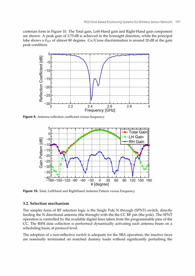
The antenna elements are printed over a common cheap FR4 substrate (εr = 4.4, h = 1.6 mm,17 μm metalization thickness) shaped in a square geometry. Figure 8(a) shows a photographof the antenna prototypes. Figure 9 shows the antenna reflection coefficient versus frequency.The 10 dB return loss bandwidth cover the entire ISM band. The antenna pattern is depicted in
146 New Approach of Indoor and Outdoor Localization Systems
RSSI/DoA Based Positioning Systems for Wireless Sensor Network 9
cartesian form in Figure 10. The Total gain, Left-Hand gain and Right-Hand gain componentare shown. A peak gain of 3.75 dB is achieved in the boresight direction, while the principallobe shows a θHP of almost 80 degrees. Co/Cross discrimination is around 20 dB at the gainpeak condition.
2 2.2 2.4 2.6 2.8 3−30
−25
−20
−15
−10
−5
0
Frequency [GHz]
Ref
lect
ion
Coe
ffici
ent [
dB]
Figure 9. Antenna reflection coefficient versus frequency.
−180−150−120 −90 −60 −30 0 30 60 90 120 150 180−40−35−30−25−20−15−10−5
05
θ [degree]
Gai
n P
atte
rn [d
B]
Total GainLH GainRH Gain
Figure 10. Total, LeftHand and RightHand Antenna Pattern versus Frequency.
3.2. Selection mechanism
The simpler form of RF selection logic is the Single Pole N through (SPNT) switch, directlyfeeding the N directional antenna (the through) with the the CC RF pin (the pole). The SPNToperation is controlled by the available digital lines taken from the programmable pins of theCC. The RSSI data collection is performed dynamically activating each antenna beam on ascheduling basis, at protocol level.
The adoption of a non-reflective switch is adequate for the SBA operation; the inactive facesare nominally terminated on matched dummy loads without significantly perturbing the
147RSSI/DoA Based Positioning Systems for Wireless Sensor Network

10 Will-be-set-by-IN-TECH
0−3
−6−9
−12−15
0 1530
45
60
75
90
105
120
135
150165180195
210
225
240
255
270
285
300
315
330345
(a) N = 4, θHB = 60
0−3
−6−9
−12−15
0 1530
45
60
75
90
105
120
135
150165180195
210
225
240
255
270
285
300
315
330345
(b) N = 4, θHB = 90
0−3
−6−9
−12−15
0 1530
45
60
75
90
105
120
135
150165180195
210
225
240
255
270
285
300
315
330345
(c) N = 6, θHB = 60
0−3
−6−9
−12−15
0 1530
45
60
75
90
105
120
135
150165180195
210
225
240
255
270
285
300
315
330345
(d) N = 6, θHB = 90
Figure 11. Regular arrangement of 4 and 6 antenna beams. Each pattern is modeled after Eq. 8, withθn = 2πn/N.
radiation pattern of the active element. The drawback of this selection mechanism is the RFloss, which is proportional on N, i.e. on the antenna number. This fact poses a limit to thesensibility of the node. Another problem, is the low isolation of the channels, which couldlead to coupling between the antennas, thus affecting the pattern generation, and corruptingthe antenna polarization.
A suitable commercial SPNT family is provided by hittite [11]. The HMC family is composedby non-reflective SPNT which exhibits moderate insertion loss and adequate isolation for theapplication in exam. For example the HMC252QS24 SP4T, exhibits moderate insertion loss of1 dB (over the channels) and an isolation in excess of than 35 dB, is adequate for the applicationof interest.
4. Localization algorithm
This section describes the algorithmic approach suitable for the proposed localization system.The performances of the localization are based on the SBA characteristics and on the radiochannel conditions.
148 New Approach of Indoor and Outdoor Localization Systems
RSSI/DoA Based Positioning Systems for Wireless Sensor Network 11
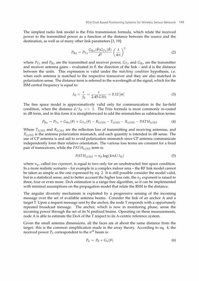
The simplest radio link model is the Friis transmission formula, which relate the receivedpower to the transmitted power as a function of the distance between the source and thedestination, as well as of many other link parameters [3, 19]:
PRx = PTxGRx(θ)GTx(θ)
d2
(λ
4π
)2(2)
where PTx and PRx are the transmitted and receiver power, GTx and GRx are the transmitterand receiver antenna gains – evaluated in θ, the direction of the link – and d is the distancebetween the units. This expression is valid under the matching condition hypothesis, i.e.when each antenna is matched to the respective transceiver and they are also matched inpolarization sense. The distance term is referred to the wavelength of the signal, which for theISM central frequency is equal to:
λ0 =cf0
=c
2.45 GHz= 0.12 [m] (3)
The free space model is approximatively valid only for communication in the far-fieldcondition, when the distance d/λ0 >> 1. The Friis formula is most commonly re-castedin dB form, and in this form it is straightforward to add the mismatches as subtraction terms:
PRx = PTx + GRx(θ) + GTx(θ)− RLOSS − TLOSS − XLOSS − PATHLOSS (4)
Where TLOSS and RLOSS are the reflection loss of transmitting and receiving antennas, andXLOSS is the antenna polarization mismatch, and each quantity is intended in dB sense. Theuse of CP antenna is and aid to avoid polarization mismatch since CP antenna communicateindependently form their relative orientation. The various loss terms are constant for a fixedpair of transceivers, while the PATHLOSS term is:
PATHLOSS = np log(4πd/λ0) (5)
where np, called loss exponent, is equal to two only for an unobstructed free space condition.In a more realistic scenario – for example in a complex indoor area – the RF link model cannotbe taken as simple as the one expressed by eq. 2. It is still possible consider the model valid,but in a statistical sense, and to better account the higher loss rate, the np exponent is raised tothree, four or even more. DoA estimation is a range-free algorithm, so it can be implementedwith minimal assumptions on the propagation model that relate the RSSI to the distance.
The angular diversity mechanism is exploited by a progressive sensing of the incomingmessage over the set of available antenna beams. Consider the link of an anchor A and atarget T. Upon a request message sent by the anchor, the node T responds with a opportunelyrepeated broadcast message. The anchor, which is now in monitoring phase, sense theincoming power through the set of its N prefixed beams. Operating on these measurements,node A is able to estimate the DoA of the T respect to its A-centric reference system.
Given the small antenna dimensions, all the faces are at about the same distance from thetarget: this is the common simplification made in the array theory. According to eq. 4, thereceived power Pn correspondent to the nth beam is:
Pn = P0 + Gn(θ) (6)
149RSSI/DoA Based Positioning Systems for Wireless Sensor Network

12 Will-be-set-by-IN-TECH
where P0 is the power of the target’s message impinging on the SBA – comprehensive of allthe loss terms – while Gn(θ) is the gain of the nth beam evaluated in the transmission angle,specified to a reference fixed to the anchor node.
Considering Figure 10, an analytical model suitable for the description of the antenna beamis the regular cardioid. A cardioid pattern is identified by its maximum gain, the half-powerradiation angle, and the nominal pointing direction specified by θ0:
G(θ) = Gmax
(12(1 + cos(θ − θ0))
)m(7)
Where the exponent m is inversely related to the aperture of the beam. This model, whilesimple, is not unrealistic and it is suitable for numerical implementation [14]. Supposinga regular known arrangement, the nominal pointing direction θn0 of each SBA element isknown, and so that the gain pattern of the set of N elements, expressed in dB form:
Gn(θ) = Gmax + 10mn log (0.5 + 0.5 cos (θ − θn0)) (8)
The radiation pattern of the T node is supposed to be omni-directional, thus it adds the samecontribute for each reaching antenna.
Figure 12. 3D plot of the analytical cardioid model expressed by Eq. 7.
The available data for the algorithm is ultimately a vector of RSSI samples, which can beconsidered a function of the incoming data, as expressed in 2.1:
RSSIn = f (Gn(θ) + P0 + Wn) n = {1, . . . , N} (9)
where Wn is the unavoidable noise term. In a realistic scenario, the noise term accounts alsofor the RSSI BIAS, with a constant but unknown term, characteristic of the specific device –i.e. < Wn >= RSSIBIAS, < W2
n >= σ2W . Typically, the RSSI register is given as an integer. A
simple but not unrealistic model for the RSSI is:
RSSIn = �Gn(θ) + P0 + Wn� n = {1, . . . , N} (10)
150 New Approach of Indoor and Outdoor Localization Systems
RSSI/DoA Based Positioning Systems for Wireless Sensor Network 13
where �·� is the floor function. Finaly, the RSSI vector are collected in sampled form, with adiscretization step ΔT:
RSSIn[k] = RSSIn(T0 + kΔT) (11)
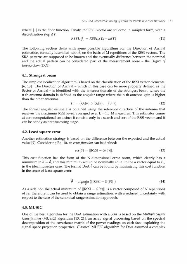
The following section deals with some possible algorithms for the Direction of Arrivalestimation, formally identified with θ, on the basis of M repetitions of the RSSI vectors. TheSBA patterns are supposed to be known and the eventually difference between the nominaland the actual pattern can be considered part of the measurement noise – the Degree ofImperfection (DOI).
4.1. Strongest beam
The simplest localization algorithm is based on the classification of the RSSI vector elements.[6, 13]. The Direction of Arrival – which in this case can be more properly defined as theSector of Arrival – is identified with the antenna domain of the strongest beam, where then-th antenna domain is defined as the angular range where the n-th antenna gain is higherthan the other antennas:
Di = {Gj(θ) > Gi(θ), j �= i} (12)
The formal angular estimate is obtained using the reference direction of the antenna thatreceives the maximum RSSI level, averaged over k = 1. . . M measures. This estimator comesat zero computational cost, since it consists only in a search and sort of the RSSI vector, and itcan be handy as preprocessing stage.
4.2. Least square error
Another estimation strategy is based on the difference between the expected and the actualvalue [9]. Considering Eq. 10, an error function can be defined:
err(θ) = ||RSSI − G(θ)||. (13)
This cost function has the form of the N-dimensional error norm, which clearly has aminimum in θ = θ, and this minimum would be nominally equal to the a vector equal to P0,in the ideal noiseless case. The formal DoA θ can be found by minimizing this cost functionin the sense of least square error:
θ = argminθ
(||RSSI − G(θ)||) (14)
As a side not, the actual minimum of ||RSSI − G(θ)|| is a vector composed of N repetitionsof P0, therefore it can be used to obtain a range estimation, with a reduced uncertainty withrespect to the case of the canonical range estimation approach.
4.3. MUSIC
One of the best algorithm for the DoA estimation with a SBA is based on the Multiple SignalClassification (MUSIC) algorithm [13, 21], an array signal processing based on the spectraldecomposition of the covariance matrix of the power readings on each face, exploiting thesignal space projection properties. Classical MUSIC algorithm for DoA assumed a complex
151RSSI/DoA Based Positioning Systems for Wireless Sensor Network
14 Will-be-set-by-IN-TECH
signal – i.e. module and phase – but a variant where no phase information is required ispossible, which means an algorithm based on RSSI only [14, 15, 24].
The MUSIC assumes readings expressed by the following linear model:⎡⎢⎣
y1[k]...
yN [k]
⎤⎥⎦ =
⎡⎢⎣
G1(θ)...
GN(θ)
⎤⎥⎦ x[k] +
⎡⎢⎣
w1[k]...
wN [k]
⎤⎥⎦ (15)
where yn(m) is the power in linear form estimated on face n upon reception of the mth message– yn = 10(RSSIn/10) –, while x(m) is the impinging signal affected by a N-dimensional W(k)noise vector.
The data correlation matrix – Ryy– estimated on based of K repetitions, is given by:
Ryy = E[y[k]y[k]�
]=
1K
K
∑k=1
y[k]y[k]� (16)
It is possible to demonstrate that:
Ryy =M
∑m=i
σ2x G(θ) + σ2
w I (17)
where σ2x = E|x2
n[k]| is the power of the nth signal and σ2w = E|w2
w[m]| is the noise power.Thus, applying the single value decomposition, the set of the following matrices is obtained:
Ryy = USU∗ (18)
Considering only an incoming signal, a partition of the space spanned by the columns ofU = [Ux, Uw] is obtained: We refer to Ux as the signal subspace. Similarly, Un is the noisesubspace. Since U is a unitary matrix the signal and noise subspaces are orthogonal, so thatUxUn = 0. Thus we define a pseudo-spectrum:
PMUSIC(θ) =1
G(θ)Un(19)
that exhibits a sharp maximum for angle supposedly close to the true DoA, formally identifiedwith:
θ = argmaxθ
PMUSIC (θ) . (20)
5. Simulated experimentIn this section, a set of simulated localization experiments is presented. Each communicationprocess involved in the simulation is modeled after eq. 10, considering also the case of theincoming power lower than receiver sensitivity. The geometrical quantities are analyticallydetermined, and the communication noise is generated as a random number with a Gaussianstatistic. Each simulation is parametrized by a set of geometrical, physical and statisticalparameters. For the sake of simplicity, the only algorithm considered in the following sectionsis MUSIC, since it has the best performance/cost trade-off.
152 New Approach of Indoor and Outdoor Localization Systems
RSSI/DoA Based Positioning Systems for Wireless Sensor Network 15
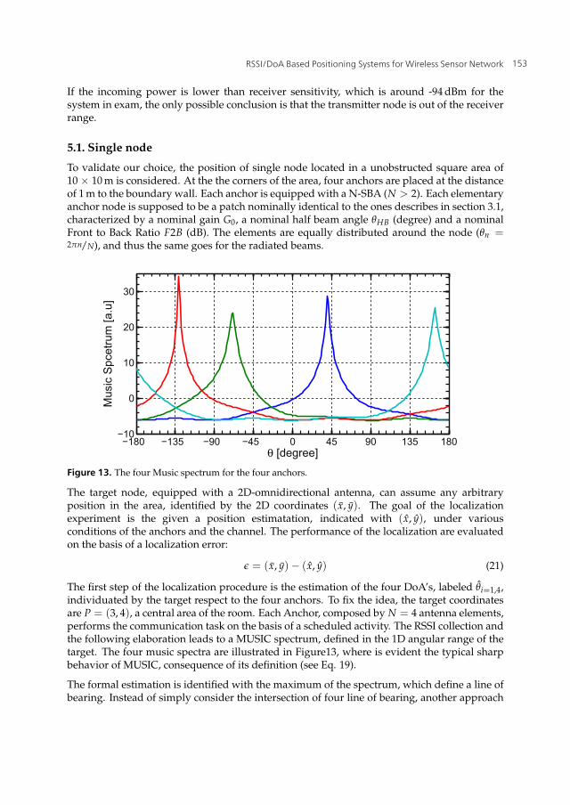
If the incoming power is lower than receiver sensitivity, which is around -94 dBm for thesystem in exam, the only possible conclusion is that the transmitter node is out of the receiverrange.
5.1. Single node
To validate our choice, the position of single node located in a unobstructed square area of10 × 10 m is considered. At the the corners of the area, four anchors are placed at the distanceof 1 m to the boundary wall. Each anchor is equipped with a N-SBA (N > 2). Each elementaryanchor node is supposed to be a patch nominally identical to the ones describes in section 3.1,characterized by a nominal gain G0, a nominal half beam angle θHB (degree) and a nominalFront to Back Ratio F2B (dB). The elements are equally distributed around the node (θn =2πn/N), and thus the same goes for the radiated beams.
−180 −135 −90 −45 0 45 90 135 180−10
0
10
20
30
θ [degree]
Mus
ic S
pcet
rum
[a.u
]
Figure 13. The four Music spectrum for the four anchors.
The target node, equipped with a 2D-omnidirectional antenna, can assume any arbitraryposition in the area, identified by the 2D coordinates (x, y). The goal of the localizationexperiment is the given a position estimatation, indicated with (x, y), under variousconditions of the anchors and the channel. The performance of the localization are evaluatedon the basis of a localization error:
ε = (x, y)− (x, y) (21)
The first step of the localization procedure is the estimation of the four DoA’s, labeled θi=1,4,individuated by the target respect to the four anchors. To fix the idea, the target coordinatesare P = (3, 4), a central area of the room. Each Anchor, composed by N = 4 antenna elements,performs the communication task on the basis of a scheduled activity. The RSSI collection andthe following elaboration leads to a MUSIC spectrum, defined in the 1D angular range of thetarget. The four music spectra are illustrated in Figure13, where is evident the typical sharpbehavior of MUSIC, consequence of its definition (see Eq. 19).
The formal estimation is identified with the maximum of the spectrum, which define a line ofbearing. Instead of simply consider the intersection of four line of bearing, another approach
153RSSI/DoA Based Positioning Systems for Wireless Sensor Network

16 Will-be-set-by-IN-TECH
is proposed. A modified spectrum is derived after the music estimation. The analyticalexpression of this auxiliary spectrum is:
MAPi(x, y) = exp
⎛⎝−
(θi(x, y)− θ
σθ
)2⎞⎠ (22)
Where θi(x, y) is a function, defined respect to the i-th anchor, which map each point of thearea to the azimuth angle θ seen by the anchor. This map is a function of the area and theanchor position, which are defined before the experiment, thus the map is build in a off-linepreprocessing phase. The term σθ is taken proportional to the standard deviation of the RSSImessage, in order to take account of the intrinsic uncertainty of the link model. This spectrumredefinition leads to the four music maps, plotted in Figure14. Each map has a radial behavior,with a linear region of high probability around the line of bearing, and a decreasing behaviordeparting from this straight line. The product of the four spectra generate a global musicspectrum, which synthesize the information of the four anchors. The peak of the spectrumidentifies the estimated position of the target, as depicted in Figure15. The advantage of thisapproach is that a single unreliable DoA estimation is filtered out by the product, while theintersection of two reliable estimation is exalted.
5.2. Sensor network
In typical wireless sensor network application, the localization involves computing theposition of the set of numerous nodes in a 2D space. The nodes are supposed to be noninteragent, i.e. they not collaborate for the localization service, but they neither interfere.According to the previous analysis we will use the same approach based on the music map.The procedure was evaluated by generating a 13 × 13 nodes network, regularly spaced in agrid of 8m × 8 m centered in the same 10 × 10 m area.
A first simulation is depicted in Figure16. The pathloss exponent is np = 2 and the σRSSIis 3 dB. The SBA anchors are made of N = 4 antenna elements are characterized by a gainGn = 3 dB and a θHB = 50, while the target is equipped with an regular 2D-omnidirectionalantenna (GT = 0 dB). For each node of the network, a local error is computed as the euclideannorm of the distance between actual and estimated position. In Figure17 an histogram ofthe global computed errors is depicted. To summarize, with the described condition, a meanabsolute error of 0.75 m (meanx = 0.51 m, meany = 0.50 m) and a max absolute error of 1.80 m(maxx = 1.5 m, maxy = 1.3 m) is evaluated. As expected, the minimal error condition isaround the center of the area, where the four anchors show the best collaboration effect. Thenodes located too close to one of four anchors suffers for a biased estimation, as testified bythe error arrows. This was expected, since the combination of the four map is unbalanced.Nevertheless, the error seems systematic, thus eventually resolvable.
To pursue a deeper investigation, a set of experiment was taken with a statistical variation ofσRSSI. The localization performance are expected to aggravate as the standard deviation – andso the noise level – increases. In Figure18(a), the mean and max errors are computed as σRSSIincreases from 0 to 15 dB. From a simple inspection is clear that both of them grow with aregular monotonic behavior, maintaining almost the same ratio of the max error ranging from2 to 3 times the level of the mean error.
154 New Approach of Indoor and Outdoor Localization Systems
RSSI/DoA Based Positioning Systems for Wireless Sensor Network 17
0 1 2 3 4 5 6 7 8 9 100123456789
10
x side [m]
y si
de [m
]
(a) Anchor #1
0 1 2 3 4 5 6 7 8 9 100123456789
10
x side [m]
y si
de [m
](b) Anchor #2
0 1 2 3 4 5 6 7 8 9 100123456789
10
x side [m]
y si
de [m
]
(c) Anchor #3
0 1 2 3 4 5 6 7 8 9 100123456789
10
x side [m]
y si
de [m
]
(d) Anchor #4
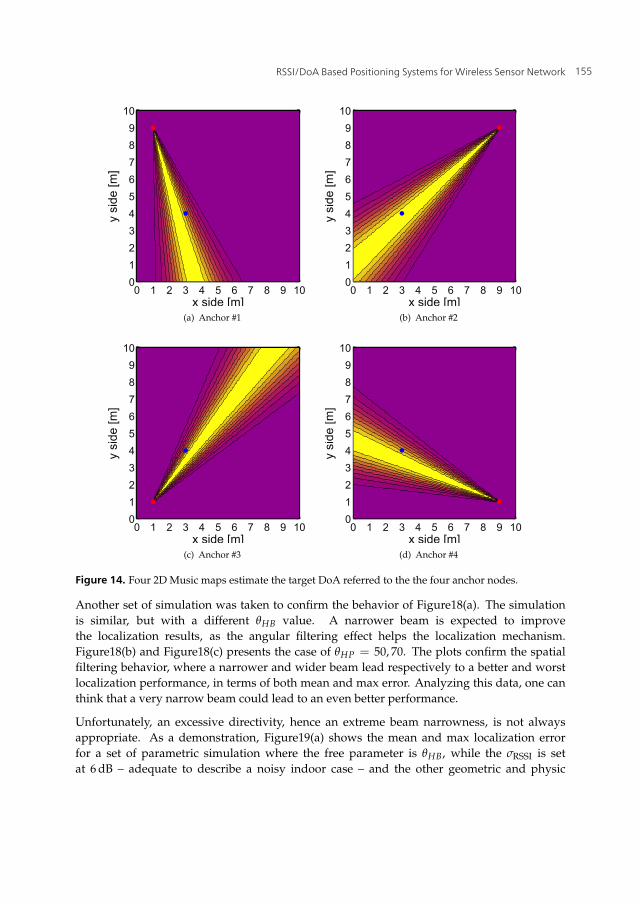
Figure 14. Four 2D Music maps estimate the target DoA referred to the the four anchor nodes.
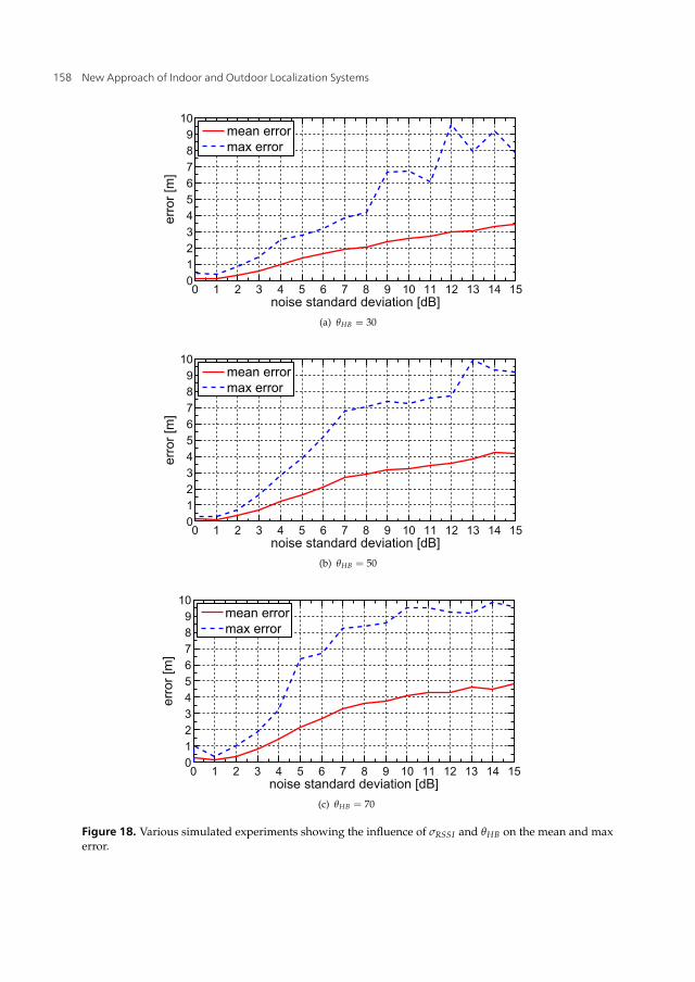
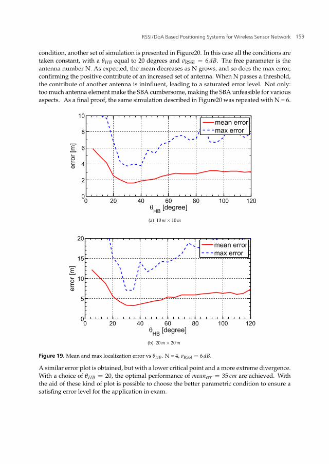
Another set of simulation was taken to confirm the behavior of Figure18(a). The simulationis similar, but with a different θHB value. A narrower beam is expected to improvethe localization results, as the angular filtering effect helps the localization mechanism.Figure18(b) and Figure18(c) presents the case of θHP = 50, 70. The plots confirm the spatialfiltering behavior, where a narrower and wider beam lead respectively to a better and worstlocalization performance, in terms of both mean and max error. Analyzing this data, one canthink that a very narrow beam could lead to an even better performance.
Unfortunately, an excessive directivity, hence an extreme beam narrowness, is not alwaysappropriate. As a demonstration, Figure19(a) shows the mean and max localization errorfor a set of parametric simulation where the free parameter is θHB, while the σRSSI is setat 6 dB – adequate to describe a noisy indoor case – and the other geometric and physic
155RSSI/DoA Based Positioning Systems for Wireless Sensor Network

18 Will-be-set-by-IN-TECH
0 1 2 3 4 5 6 7 8 9 100123456789
10
x side [m]
y si
de [m
]
Figure 15. Localization based on the global music map with the four lines of bearing identifying theestimated position.
parameters are the same of the previous simulation. The localization error increases withθHB, confirming increasing error as the antenna beams enlarge, as expected for this class ofDoA estimator. Paradoxically, when the beam is excessively narrow, the error cross a criticalpoint where it experiments a absolute minimum, and then grows abruptly reaching an evenhigher peak. The physical reason lies in the fact that with extremely directive antenna, theangular range between two adjacent narrow beam peaks is low in absolute value, leaving anuncover area, where the signal became too weak, leading to an RSSI vector with a very lowmagnitude – ||RSSI|| – and thus heavily corrupted by the random noise. For the positioningalgorithms this is an unbearable condition, where the estimation is affected by a very lowaccuracy. Figure11(b) and 11(c) depict an optimal situation, where the cumulative patterncovers the entire 2π domain with a maximum small ripple of 3 dB. The case of Figure11(a),while still satisfying, begins to show the problem of excessive directivity. As a further proof ofthis behavior, the same simulated experiment described by Figure19(a) is repeated in a biggerarea of 20 × 20 m. The results of the simulation are depicted in Figure19(b), where the meanand max error are almost doubled.
To avoid this issue, the directivity by itself is not a solution. A better condition is achieved ifeach antenna element is directive, but at the same time the cumulative pattern of the entireantenna set should show an isotropic coverture, as expressed in section 3. This ensure an RSSIvector whose norm ||RSSI|| is always meaningful, stronger than the noise. To demonstrate this
156 New Approach of Indoor and Outdoor Localization Systems

RSSI/DoA Based Positioning Systems for Wireless Sensor Network 19
0 1 2 3 4 5 6 7 8 9 100123456789
10
x side [m]
y si
de [m
]
Figure 16. Localization of wireless senor network in a indoor area. The dots represent the actualposition, while the square are the estimated positions.
0 0.5 1 1.50
5
10
15
20
localization error
coun
t
Figure 17. Localization error histogram for the simulation results of Figure16.
157RSSI/DoA Based Positioning Systems for Wireless Sensor Network
20 Will-be-set-by-IN-TECH
0 1 2 3 4 5 6 7 8 9 10 11 12 13 14 150123456789
10
noise standard deviation [dB]
erro
r [m
]
mean errormax error
(a) θHB = 30
0 1 2 3 4 5 6 7 8 9 10 11 12 13 14 150123456789
10
noise standard deviation [dB]
erro
r [m
]
mean errormax error
(b) θHB = 50
0 1 2 3 4 5 6 7 8 9 10 11 12 13 14 150123456789
10
noise standard deviation [dB]
erro
r [m
]
mean errormax error
(c) θHB = 70
Figure 18. Various simulated experiments showing the influence of σRSSI and θHB on the mean and maxerror.
158 New Approach of Indoor and Outdoor Localization Systems
RSSI/DoA Based Positioning Systems for Wireless Sensor Network 21
condition, another set of simulation is presented in Figure20. In this case all the conditions aretaken constant, with a θHB equal to 20 degrees and σRSSI = 6 dB. The free parameter is theantenna number N. As expected, the mean decreases as N grows, and so does the max error,confirming the positive contribute of an increased set of antenna. When N passes a threshold,the contribute of another antenna is ininfluent, leading to a saturated error level. Not only:too much antenna element make the SBA cumbersome, making the SBA unfeasible for variousaspects. As a final proof, the same simulation described in Figure20 was repeated with N = 6.
0 20 40 60 80 100 1200
2
4
6
8
10
θHB [degree]
erro
r [m
]
mean errormax error
(a) 10 m × 10 m
0 20 40 60 80 100 1200
5
10
15
20
θHB [degree]
erro
r [m
]
mean errormax error
(b) 20 m × 20 m
Figure 19. Mean and max localization error vs θHB. N = 4, σRSSI = 6 dB.
A similar error plot is obtained, but with a lower critical point and a more extreme divergence.With a choice of θHB = 20, the optimal performance of meanerr = 35 cm are achieved. Withthe aid of these kind of plot is possible to choose the better parametric condition to ensure asatisfing error level for the application in exam.
159RSSI/DoA Based Positioning Systems for Wireless Sensor Network

22 Will-be-set-by-IN-TECH
2 3 4 5 6 7 8 9 100123456789
10
antenna number
erro
r [m
]mean errormax error
Figure 20. Mean and max localization error vs N. θHB = 20 degrees, σRSSI = 6 dB.
0 20 40 60 80 100 1200
2
4
6
8
10
θHB [degree]
erro
r [m
]
mean errormax error
Figure 21. Mean and max localization error vs θHB. N = 6, σRSSI = 6 dB.
6. Conclusions
In this paper, the concepts for an indoor localization system suitable for a Wireless SensorNetwork in a GPS-denied scenario was presented. The localization of sensor nodes in anecessary tasks to give position-awareness to the nodes, a physical information leading toa vast range of impacting applications. The problem was addressed in terms of systemicapproach, suitable hardware, consequent algorithm and estimated performance.
The proposed localization system is based on the Direction of Arrival approach, implementedmanipulating Radio Signals. The position of a generic sensor node in the network is estimatedon the basis of its RF communication with a master node, without the need of other spatialsensors. Equipped with a complex switched beam antenna, The master node serves as anchor.The localization algorithm relies on the collaboration of a set of anchor nodes, responsible ofindependent DoA estimations. The proposed algorithm operates on the RSSI-meter, the coarsepower meter embedded in almost all the modern commercial wireless devices. In particular,
160 New Approach of Indoor and Outdoor Localization Systems

RSSI/DoA Based Positioning Systems for Wireless Sensor Network 23
the CC2430 System-on-a-Chip was individuated as the best hardware for the master and thesensor nodes.
Range measurement are extremely inaccurate in indoor area, making traditional range-basedalgorithm like trilateration fail in hostile area like complex indoor environments. The RSSIdata, while affected by numerous noise sources, are suitable for the Direction of Arrivalalgorithm, which is a range-free algorithm, an approach which does not rely on rangeestimation. The results showed in this paper have demonstrated that a WSN system madeof COTS-based nodes is suitable for in-door positioning service. A wide dynamic of cases,with a punctual correlation to the physic and statistical parameters, gives a exemplary designprinciple for the structure of the nodes, with particular emphasis on sub-antenna system.
Author details
Stefano Maddio, Alessandro Cidronali, Gianfranco ManesDepartment of Electronics and Telecommunication - University of Florence, Via S. Marta 3, 50139Florence, Italy
7. References
[1] Akyildiz, I., Su, W., Sankarasubramaniam, Y. & Cayirci, E. [2002]. A survey on sensornetworks, Communications magazine, IEEE 40(8): 102–114.
[2] Arora, A., Dutta, P., Bapat, S., Kulathumani, V., Zhang, H., Naik, V., Mittal, V., Cao, H.,Demirbas, M., Gouda, M. et al. [2004]. A line in the sand: a wireless sensor network fortarget detection, classification, and tracking, Computer Networks 46(5): 605–634.
[3] Ash, J. & Potter, L. [2004]. Sensor network localization via received signal strengthmeasurements with directional antennas, Proceedings of the 2004 Allerton Conference onCommunication, Control, and Computing, pp. 1861–1870.
[4] Carver, K. & Mink, J. [1981]. Microstrip antenna technology, Antennas and Propagation,IEEE Transactions on [legacy, pre-1988] 29(1): 2–24.
[5] Cidronali, A., Maddio, S., Giorgetti, G., Magrini, I., Gupta, S. & Manes, G. [2009]. A2.45 ghz smart antenna for location-aware single-anchor indoor applications, MicrowaveSymposium Digest, 2009. MTT’09. IEEE MTT-S International, IEEE, pp. 1553–1556.
[6] Cidronali, A., Maddio, S., Giorgetti, G. & Manes, G. [2010]. Analysis and performanceof a smart antenna for 2.45-ghz single-anchor indoor positioning, Microwave Theory andTechniques, IEEE Transactions on 58(1): 21–31.
[7] Djuknic, G. & Richton, R. [2001]. Geolocation and assisted gps, Computer 34(2): 123–125.[8] Garg, Bahl, I. [2001]. Microstrip Antenna Design Handbook, Artech House.[9] Giorgetti, G. [2007]. Resource-Constrained Localization in Sensor Networks, PhD thesis,
Universita’ Degli Studi di Firenze, Italy.[10] He, T., Krishnamurthy, S., Stankovic, J., Abdelzaher, T., Luo, L., Stoleru, R., Yan, T., Gu,
L., Hui, J. & Krogh, B. [2004]. Energy-efficient surveillance system using wireless sensornetworks, Proceedings of the 2nd international conference on Mobile systems, applications, andservices, ACM, pp. 270–283.
[11] Hittite [2012]. http://www.hittite.com/.[12] Hofmann-Wellenhof, B., Lichtenegger, H. & Collins, J. [1993]. Global positioning system.
theory and practice., Global Positioning System. Theory and practice., by Hofmann-Wellenhof,
161RSSI/DoA Based Positioning Systems for Wireless Sensor Network
24 Will-be-set-by-IN-TECH
B.; Lichtenegger, H.; Collins, J.. Springer, Wien (Austria), 1993, 347 p., ISBN 3-211-82477-4,Price DM 79.00. ISBN 0-387-82477-4 (USA). 1.
[13] Krim, H. & Viberg, M. [1996]. Two decades of array signal processing research: theparametric approach, Signal Processing Magazine, IEEE 13(4): 67–94.
[14] Maddio, S., Cidronali, A., Giorgetti, G. & Manes, G. [2010]. Calibration of a 2.45 ghzindoor direction of arrival system based on unknown antenna gain, Radar Conference(EuRAD), 2010 European, IEEE, pp. 77–80.
[15] Maddio, S., Cidronali, A. & Manes, G. [2010]. An azimuth of arrival detector based ona compact complementary antenna system, Wireless Technology Conference (EuWIT), 2010European, IEEE, pp. 249–252.
[16] Maddio, S., Cidronali, A. & Manes, G. [2011]. A new design method for single-feedcircular polarization microstrip antenna with an arbitrary impedance matchingcondition, IEEE Transactions on Antennas and Propagation 59(2): 379–389.
[17] Malhotra, N., Krasniewski, M., Yang, C., Bagchi, S. & Chappell, W. [2005]. Locationestimation in ad hoc networks with directional antennas, Distributed Computing Systems,2005. ICDCS 2005. Proceedings. 25th IEEE International Conference on, IEEE, pp. 633–642.
[18] Mukhopadhyay, S. [2012]. Smart Sensing Technology for Agriculture and EnvironmentalMonitoring, Vol. 146, Springer Verlag.
[19] Patwari, N., Ash, J., Kyperountas, S., Hero III, A., Moses, R. & Correal, N. [2005]. Locatingthe nodes: cooperative localization in wireless sensor networks, Signal ProcessingMagazine, IEEE 22(4): 54–69.
[20] Schantz, H. [2011]. On the origins of rf-based location, Wireless Sensors and SensorNetworks (WiSNet), 2011 IEEE Topical Conference on, IEEE, pp. 21–24.
[21] Schmidt, R. [1986]. Multiple emitter location and signal parameter estimation, Antennasand Propagation, IEEE Transactions on 34(3): 276–280.
[22] Werner-Allen, G., Lorincz, K., Ruiz, M., Marcillo, O., Johnson, J., Lees, J. & Welsh, M.[2006]. Deploying a wireless sensor network on an active volcano, Internet Computing,IEEE 10(2): 18–25.
[23] Yick, J., Mukherjee, B. & Ghosal, D. [2008]. Wireless sensor network survey, Computernetworks 52(12): 2292–2330.
[24] Zekavat, R. & Buehrer, R. [2011]. Handbook of Position Location: Theory, Practice andAdvances, Vol. 27, Wiley-IEEE Press.
162 New Approach of Indoor and Outdoor Localization Systems