R&S®NRP USB and LAN Power Sensors - Rohde & … R&S®NRP USB and LAN Power Sensors At a glance The...
20
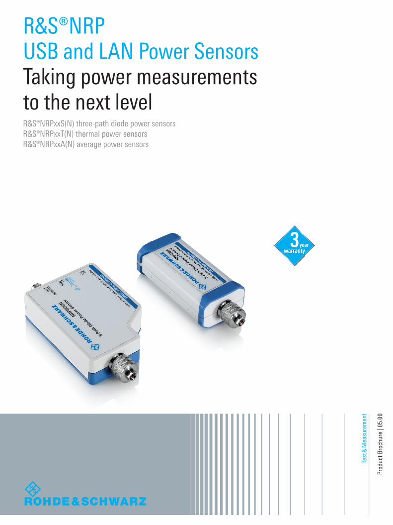
Test & Measurement Product Brochure | 05.00 R&S®NRP USB and LAN Power Sensors Taking power measurements to the next level R&S®NRPxxS(N) three-path diode power sensors R&S®NRPxxT(N) thermal power sensors R&S®NRPxxA(N) average power sensors year
Transcript of R&S®NRP USB and LAN Power Sensors - Rohde & … R&S®NRP USB and LAN Power Sensors At a glance The...
Test
& M
easu
rem
ent
Prod
uct B
roch
ure
| 05.
00
R&S®NRPUSB and LAN Power Sensors Taking power measurements to the next levelR&S®NRPxxS(N) three-path diode power sensorsR&S®NRPxxT(N) thermal power sensorsR&S®NRPxxA(N) average power sensors
year
NRP-Family_bro_en_3607-0852-12_v0500.indd 1 31.10.2016 12:28:03

2
R&S®NRP USB and LAN Power SensorsAt a glanceThe R&S®NRP power sensors have long been recognized for delivering supreme precision and speed. The R&S®NRPxxS(N), R&S®NRPxxT(N)and R&S®NRPxxA(N) power sensors take power measurements to the next level. They offer USB capability and can be additionally controlled via LAN. This makes the R&S®NRP power meter portfolio unique in the industry.
The R&S®NRPxxS(N) three-path diode power sensors, R&S®NRPxxT(N) thermal power sensors and R&S®NRPxxA(N) average power sensors are self- contained, fully characterized instruments. They can be operated with the R&S®NRP2 base unit, with a laptop/PC via USB, and with many Rohde & Schwarz instruments (e.g. signal gen-erators, signal and spectrum analyzers, network analyzers). The R&S®NRPxxSN, R&S®NRPxxTN and R&S®NRPxxAN power sensors additionally offer LAN capability, allowing remote control over large distances.
Key facts ❙ Maximum dynamic range: –70 dBm to +45 dBm ❙ Frequency range: DC to 110 GHz ❙ More than 50 000 readings/s ❙ Flexible operation with R&S®NRP2 base unit, laptop/PC and many Rohde & Schwarz instruments
❙ Control and monitoring via LAN and USB ❙ Easy LAN operation from a web browser ❙ R&S®NRPxxS(N) for widest dynamic range ❙ R&S®NRPxxT(N) for highest accuracy ❙ R&S®NRPxxA(N) for EMC applications
NRP-Family_bro_en_3607-0852-12_v0500.indd 2 31.10.2016 12:28:06
Rohde & Schwarz R&S®NRP USB and LAN Power Sensors 3
R&S®NRP USB and LAN Power SensorsBenefits and key features
Functions and performance features ❙ Fully characterized power sensors ❙ Minimizing measurement uncertainty ❙ Intelligent averaging function minimizes measurement time
❙ Versatile measurement functions ❙ USBTMC for easy system integration ❙ Built-in trigger I/O port ❙ Sensor status at a glance with status LED ❙ Detachable cables for flexible operation ▷ page 4
Intelligent, LAN enabled power measurements ❙ Almost every sensor available as LAN model ❙ Remote monitoring via LAN over any distance ❙ Power supply via Power over Ethernet (PoE) ❙ Built-in web GUI with full power measurement support ▷ page 7
R&S®NRPxxS(N) three-path diode power sensors ❙ Ideal for universal applications ❙ 93 dB dynamic range thanks to improved three-path concept
❙ Unprecedented measurement speed and accuracy even at low levels
❙ More than 50 000 readings/s ❙ 10 000 triggered measurements/s ❙ Sensors for high-power applications ▷ page 9
R&S®NRP33SN-V TVAC-compliant three-path diode power sensor ❙ Specially designed for use in thermal vacuum (TVAC) chambers
❙ Outgassing reduced to a minimum ▷ page 12
R&S®NRPxxT(N) thermal power sensors ❙ Outstanding performance for reference applications ❙ Excellent impedance matching ❙ Sophisticated connector concept ❙ Internal calibration test ▷ page 13
R&S®NRPxxA(N) EMC average power sensors ❙ Specially designed for EMC applications ▷ page 15
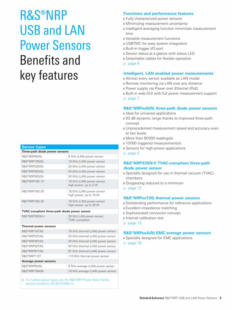
Sensor typesThree-path diode power sensors
R&S®NRP8S(N) 8 GHz (LAN) power sensor
R&S®NRP18S(N) 18 GHz (LAN) power sensor
R&S®NRP33S(N) 33 GHz (LAN) power sensor
R&S®NRP40S(N) 40 GHz (LAN) power sensor
R&S®NRP50S(N) 50 GHz (LAN) power sensor
R&S®NRP18S-10 18 GHz (LAN) power sensor,high power, up to 2 W
R&S®NRP18S-20 18 GHz (LAN) power sensorhigh power, up to 15 W
R&S®NRP18S-25 18 GHz (LAN) power sensorhigh power, up to 30 W
TVAC-compliant three-path diode power sensor
R&S®NRP33SN-V 33 GHz LAN power sensor, TVAC-compliant
Thermal power sensors
R&S®NRP18T(N) 18 GHz thermal (LAN) power sensor
R&S®NRP33T(N) 33 GHz thermal (LAN) power sensor
R&S®NRP40T(N) 40 GHz thermal (LAN) power sensor
R&S®NRP50T(N) 50 GHz thermal (LAN) power sensor
R&S®NRP67T(N) 67 GHz thermal (LAN) power sensor
R&S®NRP110T 110 GHz thermal power sensor
Average power sensors
R&S®NRP6A(N) 6 GHz average (LAN) power sensor
R&S®NRP18A(N) 18 GHz average (LAN) power sensor
▷ For further sensor types, see the R&S®NRP Power Meter Family product brochure, PD 5213.5539.12
NRP-Family_bro_en_3607-0852-12_v0500.indd 3 31.10.2016 12:28:07

S-parameter correction
S-parameters stored in sensorMeasured S-parameters
s11 s12
s21 s22
Prior to S-parameter correction
Source Plane 2 Plane 1
PMeas. ≠ PDUT
Couplers,attenuators,cables, etc.
Source Plane 2 Plane 1
PMeas. = PDUTDUT
After S-parameter correction
( )
PDUT
PDUTDUT
PMeas.
Couplers,attenuators,cables, etc.
Couplers,attenuators,cables, etc.
PMeas.
4
plane to the device under test (DUT) by taking into ac-count the S-parameters for any components connected upstream of the sensor. Γ correction compensates for the effects of impedance mismatch between the source and the power sensor.
Intelligent averaging function minimizes measurement timeWith fixed noise averaging (an enhanced auto averaging function), any measurement can be optimized with re-spect to measurement time and accuracy. The averaging filter is dynamically set to the optimum averaging value to achieve a user-defined maximum noise content. This helps to minimize measurement time and maximize production throughput for a user-specified accuracy, and to sim-plify programming of remotely controlled measurement sequences.
Versatile measurement functions ❙ Continuous average mode: reliable average power measurements on CW and modulated signals
❙ Burst average mode: burst average power measurements; sensors automatically detect start and end of a burst
❙ Trace mode: display of envelope power versus time ❙ Timeslot mode: timeslot average power measurements on TDMA signals (e.g. GSM/EDGE)
❙ Time gate mode: average power measurements in up to four independent time gates with user-defined position and length
Functions and performance features
Shifting the measurement plane from 1 to 2 by using S‑parameter correction; the influence of upstream components is compensated
Fully characterized power sensorsThe R&S®NRPxxS(N), R&S®NRPxxT(N) and R&S®NRPxxA(N) power sensors are immediately ready for use. In contrast to conventional power sensors, no cali-bration is required prior to making measurements since the sensors are fully characterized over frequency, level and temperature and feature long-term stability. All cali-bration data is stored in the sensors, so they function as independent measuring instruments. Usually, no zeroing is required. Users can plug in a sensor and simply start measuring.
Minimizing measurement uncertaintyEven complex test setups represent no challenge for the R&S®NRPxxS(N), R&S®NRPxxT(N) and R&S®NRPxxA(N) power sensors. Unwanted effects such as cable losses and reflections can be compensated using offset, S- parameter and Γ correction. Offset correction is used to take into ac-count frequency-independent attenuation. S-parameter correction is used to mathematically shift the reference
NRP-Family_bro_en_3607-0852-12_v0500.indd 4 31.10.2016 12:28:08

Rohde & Schwarz R&S®NRP USB and LAN Power Sensors 5
USBTMC for easy system integrationThe R&S®NRPxxS(N), R&S®NRPxxT(N) and R&S®NRPxxA(N) power sensors are USBTMC devices and can be easily integrated into automated test setups with-out having to install additional drivers.
R&S®NRPxxS(N), R&S®NRPxxT(N) and R&S®NRPxxA(N) power sensors can be used to replace R&S®NRP-Zxx legacy power sensors with 100 % code compatibility for remote operation.
Built-in trigger I/O portThe R&S®NRPxxS(N) power sensors have integrated trig-ger capability. To measure power levels below the mini-mum trigger threshold, an external trigger signal is re-quired. Such signals can be conveniently supplied via the built-in trigger port, which can also be used as a trigger source. In the trigger master mode, a trigger signal is derived from the measured signal inside the power sen-sor and output via the trigger port. This feature can be used to determine the input and output power levels of a power amplifier when the level at the amplifier input is too low for an internally triggered measurement but the level at the amplifier output is sufficiently high. In this case, the R&S®NRPxxS(N) used for measuring the output level acts as the trigger master to trigger the input level measurement.
Sensor status at a glance with status LEDA status LED on the sensors allows the sensor status to be viewed from different angles. This is especially advanta-geous in the case of production racks with many sensors. The LED lights green to indicate error-free measurements. System-related errors, e.g. the absence of a trigger signal, are also indicated by dedicated colors. This allows users to immediately see the operating status of all sensors and quickly respond to problems.
By assigning the same color (RGB value) to a measured trace and the LED of the associated sensor, users can more easily attribute a trace to a specific sensor. This is beneficial when using multiple sensors at the same time.
Timeslot measurement of a GSM signal with exclude times at the edges of
the timeslot.
Determination of power of an EDGE burst using an R&S®NRPxxS(N) three-
path diode power sensor and the gate function; exclusion of training se-
quence in the center of the signal.
Numerical display of two continuous average measurements and their
ratio.
NRP-Family_bro_en_3607-0852-12_v0500.indd 5 31.10.2016 12:28:08
Power meterR&S®NRP2
Signal generatorse.g. R&S®SMW200A
PC/laptop
R&S®NRPxxS(N)/R&S®NRPxxT(N)/R&S®NRPxxA(N)
Supported Rohde & Schwarz instruments
Network analyzerse.g. R&S®ZVA
Signal and spectrum analyzerse.g. R&S®FSW
R&S®NRPxxS/T/A: R&S®NRP-ZK6R&S®NRPxxSN/TN/AN: R&S®NRP-ZK6
R&S®NRPxxS/T/A: R&S®NRP-ZKUR&S®NRPxxSN/TN/AN: R&S®NRP-ZKU or LAN
R&S®NRPxxS/T/A: R&S®NRP-ZK6 or R&S®NRP-ZKUR&S®NRPxxSN/TN/AN: R&S®NRP-ZK6 or R&S®NRP-ZKU
6
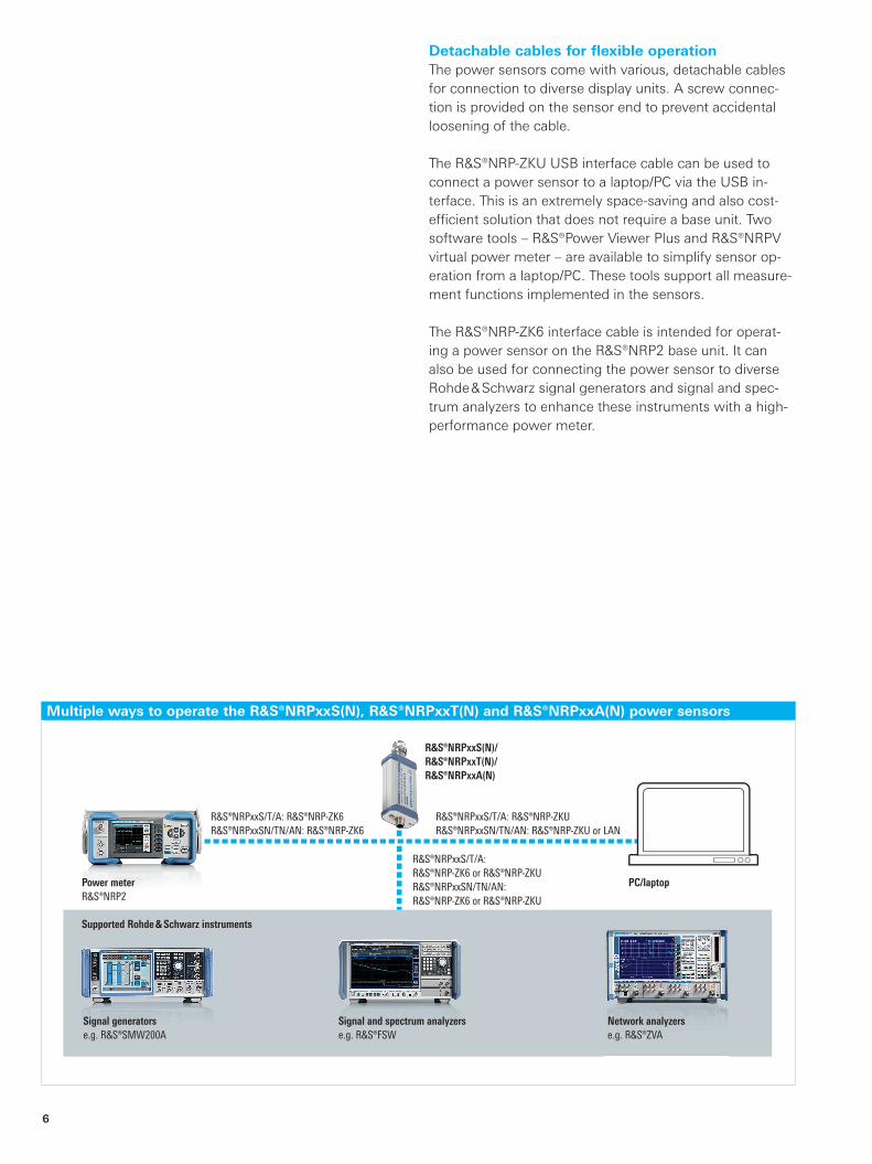
Detachable cables for flexible operationThe power sensors come with various, detachable cables for connection to diverse display units. A screw connec-tion is provided on the sensor end to prevent accidental loosening of the cable.
The R&S®NRP-ZKU USB interface cable can be used to connect a power sensor to a laptop/PC via the USB in-terface. This is an extremely space-saving and also cost-efficient solution that does not require a base unit. Two software tools – R&S®Power Viewer Plus and R&S®NRPV virtual power meter – are available to simplify sensor op-eration from a laptop/PC. These tools support all measure-ment functions implemented in the sensors.
The R&S®NRP-ZK6 interface cable is intended for operat-ing a power sensor on the R&S®NRP2 base unit. It can also be used for connecting the power sensor to diverse Rohde & Schwarz signal generators and signal and spec-trum analyzers to enhance these instruments with a high-performance power meter.
Multiple ways to operate the R&S®NRPxxS(N), R&S®NRPxxT(N) and R&S®NRPxxA(N) power sensors
NRP-Family_bro_en_3607-0852-12_v0500.indd 6 31.10.2016 12:28:08

Rohde & Schwarz R&S®NRP USB and LAN Power Sensors 7
Almost every sensor available as LAN modelEach R&S®NRPxxS three-path diode, each R&S®NRPxxA average and almost every R&S®NRPxxT thermal sensor from the R&S®NRP product range is available as a LAN model (R&S®NRPxxSN, R&S®NRPxxAN, R&S®NRPxxTN). LAN models are equipped with an additional LAN interface without compromising sensor features and performance.
Remote monitoring via LAN over any distanceThe R&S®NRPxxSN, R&S®NRPxxTN and R&S®NRPxxAN LAN power sensors are ideal for remote monitoring appli-cations, e.g. for satellite systems or particle accelerators, where sensors need to be placed at different points in the system. The LAN interface makes it easy to overcome large distances between the various test points and the control center.
Intelligent, LAN enabled power measurements
LAN interface, trigger I/O port and detachable cable for the R&S®NRPxxSN
sensors.
Operation of R&S®NRPxxSN power sensor via a web browser.
NRP-Family_bro_en_3607-0852-12_v0500.indd 7 31.10.2016 12:28:12

WLAN
LANWLAN
PoE switch R&S®NRPxxSN/TN/AN
DUT
MobileInternet
R&S®NRPxxSN/TN/AN
DUT
Internet
PoE switch
8
Power supply via Power over Ethernet (PoE)In LAN operation, the sensors are powered via a PoE- capable LAN interface on the power sensor. The LAN used must support the PoE standard, or the sensors are con-nected to the LAN via a PoE switch (e.g. R&S®NRP-ZAP1).
Built‑in web GUI with full power measurement supportThe R&S®NRPxxSN, R&S®NRPxxTN and R&S®NRPxxAN can be operated via a web interface. Using a PC connect-ed to the Internet, the power sensors can be conveniently controlled via a web browser – no additional software needs to be installed.
Simultaneous, location-independent remote monitoring of multiple R&S®NRPxxSN/TN/AN power sensors using a web browser
NRP-Family_bro_en_3607-0852-12_v0500.indd 8 31.10.2016 12:28:12
Rohde & Schwarz R&S®NRP USB and LAN Power Sensors 9
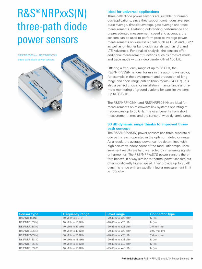
Ideal for universal applicationsThree-path diode power sensors are suitable for numer-ous applications, since they support continuous average, burst average, timeslot average, gate average and trace measurements. Featuring outstanding performance and unprecedented measurement speed and accuracy, the sensors can be used to perform precise average power measurements on wireless signals such as GSM and 3GPP as well as on higher bandwidth signals such as LTE and LTE-Advanced. For detailed analysis, the sensors offer additional measurement functions such as timeslot mode and trace mode with a video bandwidth of 100 kHz.
Offering a frequency range of up to 33 GHz, the R&S®NRP33S(N) is ideal for use in the automotive sector, for example in the development and production of long-range and short-range anti-collision radars (24 GHz). It is also a perfect choice for installation, maintenance and re-mote monitoring of ground stations for satellite systems (up to 33 GHz).
The R&S®NRP40S(N) and R&S®NRP50S(N) are ideal for measurements on microwave link systems operating at frequencies up to 50 GHz. The user benefits from short measurement times and the sensors’ wide dynamic range.
93 dB dynamic range thanks to improved three‑path conceptThe R&S®NRPxxS(N) power sensors use three separate di-ode paths, each operated in the optimum detector range. As a result, the average power can be determined with high accuracy independent of the modulation type. Mea-surement results are hardly affected by interfering signals or harmonics. The R&S®NRPxxS(N) power sensors there-fore behave in a way similar to thermal power sensors but offer significantly higher speed. They provide up to 93 dB dynamic range with an excellent lower measurement limit of –70 dBm.
R&S®NRPxxS(N) three-path diode power sensors
Sensor type Frequency range Level range Connector typeR&S®NRP8S(N) 10 MHz to 8 GHz –70 dBm to +23 dBm N (m)
R&S®NRP18S(N) 10 MHz to 18 GHz –70 dBm to +23 dBm N (m)
R&S®NRP33S(N) 10 MHz to 33 GHz –70 dBm to +23 dBm 3.5 mm (m)
R&S®NRP40S(N) 50 MHz to 40 GHz –70 dBm to +20 dBm 2.92 mm (m)
R&S®NRP50S(N) 50 MHz to 50 GHz –70 dBm to +20 dBm 2.4 mm (m)
R&S®NRP18S-10 10 MHz to 18 GHz –60 dBm to +33 dBm N (m)
R&S®NRP18S-20 10 MHz to 18 GHz –50 dBm to +42 dBm N (m)
R&S®NRP18S-25 10 MHz to 18 GHz –45 dBm to +45 dBm N (m)
R&S®NRP50S and R&S®NRP50SN
three-path diode power sensors.
NRP-Family_bro_en_3607-0852-12_v0500.indd 9 31.10.2016 12:28:14

AD
+
AD
AD
–20 dBmto +6 dBm
Pi
–70 dBmto –14 dBm
0 dBmto +23 dBm
Pm
External trigger
Chopper
Error correction
Weighting
34 dB
14 dB
10
In contrast to conventional multipath technology, adjacent diode paths in the R&S®NRPxxS(N) power sensors overlap by 6 dB. All paths are continuously and simultaneously measured. The final measurement result is achieved by ap-propriately weighting the measurement results of all paths. This innovative approach ensures a smooth transition be-tween measurement paths. Problems due to hard switch-ing between the measurement paths, such as hysteresis effects, additional measurement delays and differential nonlinearity, are eliminated. The patented sensor architec-ture also improves the signal-to-noise ratio and increases measurement speed in the transition region.
Unprecedented measurement speed and accuracy even at low levelsThe measurement speed is not only a function of the sam-pling rate. It depends to a substantial degree on the level to be measured and the desired measurement accuracy. To increase measurement accuracy, especially at low lev-els, it is necessary to average multiple measured values. While averaging reduces the noise component and thus increases measurement accuracy, it slows down the mea-surement at the same time. The R&S®NRPxxS(N) power sensors have therefore been designed with an extremely low measurement noise in mind.
As a basic rule, it can be said that a 50 % reduction in the measurement noise will reduce the measurement time by a factor of four while maintaining the same accuracy.
With a typical measurement noise of 20 pW, the R&S®NRPxxS(N) power sensors can perform measure-ments down to a lower limit of –70 dBm with the highest speed and accuracy currently available on the market.
More than 50 000 readings/sWith more than 50 000 readings/s in fast continuous aver-age mode, the R&S®NRPxxS(N) power sensors are cur-rently the fastest sensors on the market. In buffered mode, they can transmit up to 8192 measured values per block with a minimum aperture of 10 µs. This corresponds to a continuous acquisition time of 81.92 ms. Any sporadic in-terference will be reliably detected.
Innovative three-path concept
NRP-Family_bro_en_3607-0852-12_v0500.indd 10 31.10.2016 12:28:14
Variable triggered measurement points
Trigger signal (variable trigger repetition)
Minimum trigger repetition time: 100 μs
Time
Rohde & Schwarz R&S®NRP USB and LAN Power Sensors 11
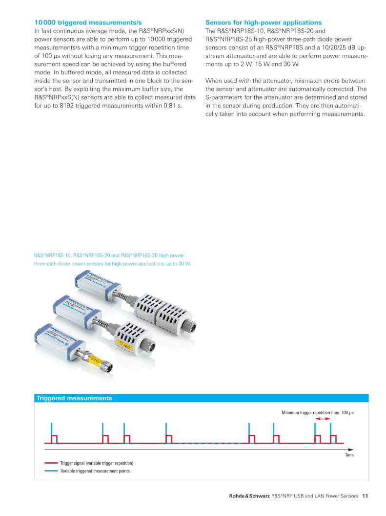
10 000 triggered measurements/sIn fast continuous average mode, the R&S®NRPxxS(N) power sensors are able to perform up to 10 000 triggered measurements/s with a minimum trigger repetition time of 100 µs without losing any measurement. This mea-surement speed can be achieved by using the buffered mode. In buffered mode, all measured data is collected inside the sensor and transmitted in one block to the sen-sor’s host. By exploiting the maximum buffer size, the R&S®NRPxxS(N) sensors are able to collect measured data for up to 8192 triggered measurements within 0.81 s.
Sensors for high-power applicationsThe R&S®NRP18S-10, R&S®NRP18S-20 and R&S®NRP18S-25 high-power three-path diode power sensors consist of an R&S®NRP18S and a 10/20/25 dB up-stream attenuator and are able to perform power measure-ments up to 2 W, 15 W and 30 W.
When used with the attenuator, mismatch errors between the sensor and attenuator are automatically corrected. The S-parameters for the attenuator are determined and stored in the sensor during production. They are then automati-cally taken into account when performing measurements.
Triggered measurements
R&S®NRP18S-10, R&S®NRP18S-20 and R&S®NRP18S-25 high-power
three-path diode power sensors for high-power applications up to 30 W.
NRP-Family_bro_en_3607-0852-12_v0500.indd 11 31.10.2016 12:28:15

12
Specially designed for use in thermal vacuum (TVAC) chambersIn the satellite sector, components, subsystems and entire satellites must be qualified in a thermal vacuum (TVAC) before they can be used in space. This increasingly re-quires highly accurate, reliable power measurements di-rectly on the DUT, i.e. in a TVAC chamber. Power sensors must therefore not only function in a high vacuum but also be able to withstand certain temperature fluctuations.
The R&S®NRP33SN-V TVAC-compliant power sensor is specially designed for these requirements. All components are baked in a vacuum chamber during the production process, so outgassing is reduced to a minimum. Venting holes in the housing ensure pressure equalization between the inside of the sensor and the environment.
The R&S®NRP33SN-V TVAC-compliant power sensor cov-ers the satellite communications frequency range up to 33 GHz and allows fast, highly accurate power measure-ments over a dynamic range of 93 dB, independent of sig-nal bandwidth and modulation type. Thanks to their LAN capability, the power sensors can be easily controlled and monitored from outside the chamber.
R&S®NRP33SN-V TVAC-compliant three-path diode power sensor
Sensor type Frequency range Level range Connector typeR&S®NRP33SN-V 10 MHz to 33 GHz –70 dBm to +23 dBm 3.5 mm (m)
R&S®NRP33SN-V
TVAC-compliant
power sensor.
NRP-Family_bro_en_3607-0852-12_v0500.indd 12 31.10.2016 12:28:17

Rohde & Schwarz R&S®NRP USB and LAN Power Sensors 13
Outstanding performance for reference applicationsThermal power sensors are especially used for complex measurement tasks where highest accuracy counts. They tolerate any type of modulation. To improve measurement accuracy, the hardware of the R&S®NRPxxT(N) thermal power sensors is designed to reduce measurement noise to a minimum and to make the sensor immune to thermal environmental effects. To achieve stable measurement re-sults, the temperature in the thermal test cell must corre-spond to the applied power. When the power is increased, the sophisticated measurement cell of the R&S®NRPxxT(N) thermal power sensors quickly attains a stable tempera-ture. When the power level is decreased, the excess heat is dissipated extremely quickly. Thus, thermal power sen-sors from Rohde & Schwarz are able to measure three times faster than comparable solutions on the market with triggered measurements and > 500 measurements/s in buffered mode – with top accuracy.
The R&S®NRPxxT(N) thermal power sensors feature an unparalleled linearity of 0.007 dB (0.16 %) up to 67 GHz and 0.010 dB (0.23 %) between 67 GHz and 110 GHz, making them the ideal choice for performing relative measurements.
These sensor characteristics are particularly beneficial in reference applications and calibration labs.
Excellent impedance matchingTo a large extent, measurement uncertainty results from multiple reflections at the source and power sensor caused by mismatch. To minimize these reflections, all thermal power sensors in the R&S®NRP family are excel-lently matched up to high frequencies, reducing measure-ment uncertainty.
R&S®NRPxxT(N) thermal power sensors
Sensor type Frequency range Level range Connector typeR&S®NRP18T(N) DC to 18 GHz –35 dBm to +20 dBm N (m)
R&S®NRP33T(N) DC to 33 GHz –35 dBm to +20 dBm 3.5 mm (m)
R&S®NRP40T(N) DC to 40 GHz –35 dBm to +20 dBm 2.92 mm (m)
R&S®NRP50T(N) DC to 50 GHz –35 dBm to +20 dBm 2.4 mm (m)
R&S®NRP67T(N) DC to 67 GHz –35 dBm to +20 dBm 1.85 mm (m)
R&S®NRP110T DC to 110 GHz –35 dBm to +20 dBm 1 mm (m)
R&S®NRP67T and R&S®NRP67TN
thermal power sensor.
NRP-Family_bro_en_3607-0852-12_v0500.indd 13 31.10.2016 12:28:18
14
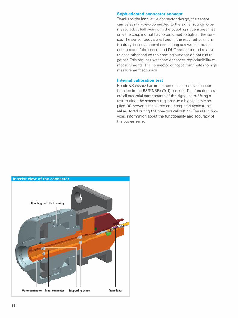
Sophisticated connector conceptThanks to the innovative connector design, the sensor can be easily screw-connected to the signal source to be measured. A ball bearing in the coupling nut ensures that only the coupling nut has to be turned to tighten the sen-sor. The sensor body stays fixed in the required position. Contrary to conventional connecting screws, the outer conductors of the sensor and DUT are not turned relative to each other and so their mating surfaces do not rub to-gether. This reduces wear and enhances reproducibility of measurements. The connector concept contributes to high measurement accuracy.
Internal calibration testRohde & Schwarz has implemented a special verification function in the R&S®NRPxxT(N) sensors. This function cov-ers all essential components of the signal path. Using a test routine, the sensor’s response to a highly stable ap-plied DC power is measured and compared against the value stored during the previous calibration. The result pro-vides information about the functionality and accuracy of the power sensor.
Interior view of the connector
Coupling nut
Outer connector Supporting beadsInner connector Transducer
Ball bearing
NRP-Family_bro_en_3607-0852-12_v0500.indd 14 31.10.2016 12:28:18

Rohde & Schwarz R&S®NRP USB and LAN Power Sensors 15
R&S®NRPxxA(N) EMC average power sensors
Specially designed for EMC applicationsIn EMC applications, usually only the average power is of interest. This is where the R&S®NRPxxA(N) average power sensors are the perfect fit. They cover measurement ranges that are used in radio telecommunications as well as the important lower frequency bands down to 8 kHz. Users benefit from the excellent properties of the three-path diode power sensors, including a dynamic range of up to 93 dB, very low influence of the modulation on the measurement and outstanding impedance matching.
Sensor type Frequency range Level range Connector typeR&S®NRP6A(N) 8 kHz to 6 GHz –70 dBm to +23 dBm N (m)
R&S®NRP18A(N) 8 kHz to 18 GHz –70 dBm to +23 dBm N (m)
R&S®NRP18A and R&S®NRP18AN
EMC average power sensor.
NRP-Family_bro_en_3607-0852-12_v0500.indd 15 31.10.2016 12:28:20
16
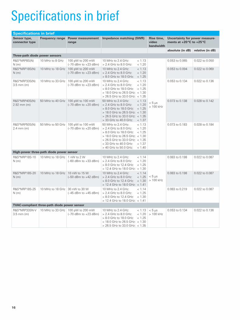
Specifications in briefSpecifications in briefSensor type, connector type
Frequency range Power measurement range
Impedance matching (SWR) Rise time, video bandwidth
Uncertainty for power measure-ments at +20 °C to +25 °C
absolute (in dB) relative (in dB)
Three-path diode power sensors
R&S®NRP8S(N)N (m)
10 MHz to 8 GHz 100 pW to 200 mW(–70 dBm to +23 dBm)
10 MHz to 2.4 GHz: < 1.13> 2.4 GHz to 8.0 GHz: < 1.20
< 5 µs> 100 kHz
0.053 to 0.065 0.022 to 0.050
R&S®NRP18S(N)N (m)
10 MHz to 18 GHz 100 pW to 200 mW(–70 dBm to +23 dBm)
10 MHz to 2.4 GHz: < 1.13> 2.4 GHz to 8.0 GHz: < 1.20> 8.0 GHz to 18.0 GHz: < 1.25
0.053 to 0.094 0.022 to 0.069
R&S®NRP33S(N)3.5 mm (m)
10 MHz to 33 GHz 100 pW to 200 mW(–70 dBm to +23 dBm)
10 MHz to 2.4 GHz: < 1.13> 2.4 GHz to 8.0 GHz: < 1.20> 8.0 GHz to 18.0 GHz: < 1.25> 18.0 GHz to 26.5 GHz: < 1.30> 26.5 GHz to 33.0 GHz: < 1.35
0.053 to 0.134 0.022 to 0.136
R&S®NRP40S(N)2.92 mm (m)
50 MHz to 40 GHz 100 pW to 100 mW(–70 dBm to +20 dBm)
50 MHz to 2.4 GHz: < 1.13> 2.4 GHz to 8.0 GHz: < 1.20> 8.0 GHz to 18.0 GHz: < 1.25> 18.0 GHz to 26.5 GHz: < 1.30> 26.5 GHz to 33.0 GHz: < 1.35> 33 GHz to 40.0 GHz: < 1.37
0.073 to 0.138 0.028 to 0.142
R&S®NRP50S(N)2.4 mm (m)
50 MHz to 50 GHz 100 pW to 100 mW(–70 dBm to +20 dBm)
50 MHz to 2.4 GHz: < 1.13> 2.4 GHz to 8.0 GHz: < 1.20> 8.0 GHz to 18.0 GHz: < 1.25> 18.0 GHz to 26.5 GHz: < 1.30> 26.5 GHz to 33.0 GHz: < 1.35> 33 GHz to 40.0 GHz: < 1.37> 40 GHz to 50.0 GHz: < 1.40
0.073 to 0.183 0.028 to 0.184
High-power three-path diode power sensor
R&S®NRP18S-10N (m)
10 MHz to 18 GHz 1 nW to 2 W(–60 dBm to +33 dBm)
10 MHz to 2.4 GHz: < 1.14> 2.4 GHz to 8.0 GHz: < 1.20> 8.0 GHz to 12.4 GHz: < 1.25> 12.4 GHz to 18.0 GHz: < 1.30
< 5 µs> 100 kHz
0.083 to 0.198 0.022 to 0.087
R&S®NRP18S-20N (m)
10 MHz to 18 GHz 10 nW to 15 W(–50 dBm to +42 dBm)
10 MHz to 2.4 GHz: < 1.14> 2.4 GHz to 8.0 GHz: < 1.25> 8.0 GHz to 12.4 GHz: < 1.30> 12.4 GHz to 18.0 GHz: < 1.41
0.083 to 0.198 0.022 to 0.087
R&S®NRP18S-25N (m)
10 MHz to 18 GHz 30 nW to 30 W(–45 dBm to +45 dBm)
10 MHz to 2.4 GHz: < 1.14> 2.4 GHz to 8.0 GHz: < 1.25> 8.0 GHz to 12.4 GHz: < 1.30> 12.4 GHz to 18.0 GHz: < 1.41
0.083 to 0.219 0.022 to 0.087
TVAC-compliant three-path diode power sensor
R&S®NRP33SN-V3.5 mm (m)
10 MHz to 33 GHz 100 pW to 200 mW(–70 dBm to +23 dBm)
10 MHz to 2.4 GHz: < 1.13> 2.4 GHz to 8.0 GHz: < 1.20> 8.0 GHz to 18.0 GHz: < 1.25> 18.0 GHz to 26.5 GHz: < 1.30> 26.5 GHz to 33.0 GHz: < 1.35
< 5 µs> 100 kHz
0.053 to 0.134 0.022 to 0.136
NRP-Family_bro_en_3607-0852-12_v0500.indd 16 31.10.2016 12:28:20

Rohde & Schwarz R&S®NRP USB and LAN Power Sensors 17
Specifications in briefSensor type, connector type
Frequency range Power measurement range
Impedance matching (SWR) Rise time, video bandwidth
Uncertainty for power measure-ments at +20 °C to +25 °C
absolute (in dB) relative (in dB)
Thermal power sensors
R&S®NRP18T(N)N (m)
DC to 18 GHz 300 nW to 100 mW (–35 dBm to +20 dBm)
DC to 100 MHz: < 1.03> 100 MHz to 2.4 GHz: < 1.06> 2.4 GHz to 12.4 GHz: < 1.13> 12.4 GHz to 18.0 GHz: < 1.16
–
0.040 to 0.082 0.010
R&S®NRP33T(N)3.5 mm (m)
DC to 33 GHz 300 nW to 100 mW (–35 dBm to +20 dBm)
DC to 100 MHz: < 1.03> 100 MHz to 2.4 GHz: < 1.06> 2.4 GHz to 12.4 GHz: < 1.13> 12.4 GHz to 18.0 GHz: < 1.16> 18.0 GHz to 26.5 GHz: < 1.22> 26.5 GHz to 33.0 GHz: < 1.28
0.040 to 0.101 0.010
R&S®NRP40T(N)2.92 mm (m)
DC to 40 GHz 300 nW to 100 mW (–35 dBm to +20 dBm)
DC to 100 MHz: < 1.03> 100 MHz to 2.4 GHz: < 1.06> 2.4 GHz to 12.4 GHz: < 1.13> 12.4 GHz to 18.0 GHz: < 1.16> 18.0 GHz to 26.5 GHz: < 1.22> 26.5 GHz to 40.0 GHz: < 1.28
0.040 to 0.108 0.010
R&S®NRP50T(N)2.4 mm (m)
DC to 50 GHz 300 nW to 100 mW (–35 dBm to +20 dBm)
DC to 100 MHz: < 1.03> 100 MHz to 2.4 GHz: < 1.06> 2.4 GHz to 12.4 GHz: < 1.13> 12.4 GHz to 18.0 GHz: < 1.16> 18.0 GHz to 26.5 GHz: < 1.22> 26.5 GHz to 40.0 GHz: < 1.28> 40.0 GHz to 50.0 GHz: < 1.30
0.040 to 0.143 0.010
R&S®NRP67T(N)1.85 mm (m)
DC to 67 GHz 300 nW to 100 mW (–35 dBm to +20 dBm)
DC to 100 MHz: < 1.03> 100 MHz to 2.4 GHz: < 1.06> 2.4 GHz to 12.4 GHz: < 1.13> 12.4 GHz to 18.0 GHz: < 1.16> 18.0 GHz to 26.5 GHz: < 1.22> 26.5 GHz to 40.0 GHz: < 1.28> 40.0 GHz to 50.0 GHz: < 1.30> 50.0 GHz to 67.0 GHz: < 1.35
0.040 to 0.248 0.010
R&S®NRP110T1 mm (m)
DC to 110 GHz 300 nW to 100 mW (–35 dBm to +20 dBm)
DC to 100 MHz: < 1.05> 100 MHz to 2.4 GHz: < 1.08> 2.4 GHz to 12.4 GHz: < 1.18> 12.4 GHz to 18.0 GHz: < 1.23> 18.0 GHz to 26.5 GHz: < 1.28> 26.5 GHz to 40.0 GHz: < 1.38> 40.0 GHz to 50.0 GHz: < 1.46> 50.0 GHz to 67.0 GHz: < 1.56> 67.0 GHz to 80.0 GHz: < 1.60> 80.0 GHz to 95.0 GHz: < 1.66> 95.0 GHz to 110 GHz: < 1.70
0.040 to 0.318 0.014
Average power sensors
R&S®NRP6A(N)N (m)
8 kHz to 6 GHz 100 pW to 200 mW(–70 dBm to +23 dBm)
8 kHz to < 20 kHz: < 1.2520 kHz to 2.4 GHz: < 1.13> 2.4 GHz to 6 GHz: < 1.20
–
0.051 to 0.056 0.022 to 0.050
R&S®NRP18A(N)N (m)
8 kHz to 18 GHz 100 pW to 200 mW(–70 dBm to +23 dBm)
8 kHz to < 20 kHz: < 1.2520 kHz to 2.4 GHz: < 1.13> 2.4 GHz to 6 GHz: < 1.20> 8 GHz to 18 GHz: < 1.25
0.051 to 0.094 0.022 to 0.069
NRP-Family_bro_en_3607-0852-12_v0500.indd 17 31.10.2016 12:28:20

18
Ordering informationDesignation Type Order No.Three-Path Diode Power Sensor
100 pW to 200 mW, 10 MHz to 8 GHz R&S®NRP8S 1419.0006.02
100 pW to 200 mW, 10 MHz to 8 GHz, LAN version R&S®NRP8SN 1419.0012.02
100 pW to 200 mW, 10 MHz to 18 GHz R&S®NRP18S 1419.0029.02
100 pW to 200 mW, 10 MHz to 18 GHz, LAN version R&S®NRP18SN 1419.0035.02
100 pW to 200 mW, 10 MHz to 33 GHz R&S®NRP33S 1419.0064.02
100 pW to 200 mW, 10 MHz to 33 GHz, LAN version R&S®NRP33SN 1419.0070.02
100 pW to 100 mW, 50 MHz to 40 GHz R&S®NRP40S 1419.0041.02
100 pW to 100 mW, 50 MHz to 40 GHz, LAN version R&S®NRP40SN 1419.0058.02
100 pW to 100 mW, 50 MHz to 50 GHz R&S®NRP50S 1419.0087.02
100 pW to 100 mW, 50 MHz to 50 GHz, LAN version R&S®NRP50SN 1419.0093.02
High-Power Three-Path Diode Power Sensor
1 nW to 2 W, 10 MHz to 18 GHz R&S®NRP18S-10 1424.6721.02
10 nW to 15 W, 10 MHz to 18 GHz R&S®NRP18S-20 1424.6738.02
30 nW to 30 W, 10 MHz to 18 GHz R&S®NRP18S-25 1424.6744.02
TVAC-Compliant Three-Path Diode Power Sensor
100 pW to 200 mW, 10 MHz to 33 GHz, LAN version, TVAC-compliant R&S®NRP33SN-V 1419.0129.02
Thermal Power Sensors
300 nW to 100 mW, DC to 18 GHz R&S®NRP18T 1424.6115.02
300 nW to 100 mW, DC to 18 GHz, LAN version R&S®NRP18TN 1424.6121.02
300 nW to 100 mW, DC to 33 GHz R&S®NRP33T 1424.6138.02
300 nW to 100 mW, DC to 33 GHz, LAN version R&S®NRP33TN 1424.6144.02
300 nW to 100 mW, DC to 40 GHz R&S®NRP40T 1424.6150.02
300 nW to 100 mW, DC to 40 GHz, LAN version R&S®NRP40TN 1424.6167.02
300 nW to 100 mW, DC to 50 GHz R&S®NRP50T 1424.6173.02
300 nW to 100 mW, DC to 50 GHz, LAN version R&S®NRP50TN 1424.6180.02
300 nW to 100 mW, DC to 67 GHz R&S®NRP67T 1424.6196.02
300 nW to 100 mW, DC to 67 GHz, LAN version R&S®NRP67TN 1424.6209.02
300 nW to 100 mW, DC to 110 GHz R&S®NRP110T 1424.6215.02
Average Power Sensors
100 pW to 200 mW, 8 kHz to 6 GHz R&S®NRP6A 1424.6796.02
100 pW to 200 mW, 8 kHz to 6 GHz, LAN version R&S®NRP6AN 1424.6809.02
100 pW to 200 mW, 8 kHz to 18 GHz R&S®NRP18A 1424.6815.02
100 pW to 200 mW, 8 kHz to 18 GHz, LAN version R&S®NRP18AN 1424.6821.02
Accessories (cables, additional equipment, etc.)
USB Interface Cable, length: 0.75 m R&S®NRP-ZKU 1419.0658.02
USB Interface Cable, length: 1.5 m R&S®NRP-ZKU 1419.0658.03
USB Interface Cable, length: 3 m R&S®NRP-ZKU 1419.0658.04
USB Interface Cable, length: 5 m R&S®NRP-ZKU 1419.0658.05
Six-Pole Interface Cable, length: 1.5 m R&S®NRP-ZK6 1419.0664.02
Six-Pole Interface Cable, length: 3 m R&S®NRP-ZK6 1419.0664.03
Six-Pole Interface Cable, length: 5 m R&S®NRP-ZK6 1419.0664.04
Sensor Hub R&S®NRP-Z5 1146.7740.02
Power over Ethernet (PoE) Switch R&S®NRP-ZAP1 1419.0829.00
Documentation
Documentation of Calibration Values R&S®DCV-1 0240.2187.06
Printout of DCV (in combination with DCV only) R&S®DCV-ZP 1173.6506.02
Accredited Calibration, for R&S®NRPxxS(N), R&S®NRPxxT(N) and R&S®NRPxxA(N) power sensors
R&S®NRP-ACA 1419.0812.00
NRP-Family_bro_en_3607-0852-12_v0500.indd 18 31.10.2016 12:28:20

Rohde & Schwarz R&S®NRP USB and LAN Power Sensors 19
WarrantyPower sensors and R&S®NRP-Z5 3 years
All other items 1 year
Options
Extended Warranty, one year R&S®WE1 Please contact your local Rohde & Schwarz sales office.Extended Warranty, two years R&S®WE2
Extended Warranty with Calibration Coverage, one year R&S®CW1
Extended Warranty with Calibration Coverage, two years R&S®CW2
For data sheet, see PD 3607.0852.22 and www.rohde-schwarz.com
Your local Rohde & Schwarz expert will help you determine the optimum solution for your requirements.To find your nearest Rohde & Schwarz representative, visit www.sales.rohde-schwarz.com
NRP-Family_bro_en_3607-0852-12_v0500.indd 19 31.10.2016 12:28:20

R&S® is a registered trademark of Rohde & Schwarz GmbH & Co. KG
Trade names are trademarks of the owners
PD 3607.0852.12 | Version 05.00 | October 2016 (sk)
R&S®NRP USB and LAN Power Sensors
Data without tolerance limits is not binding | Subject to change
© 2016 Rohde & Schwarz GmbH & Co. KG | 81671 Munich, Germany
Service that adds value❙ Worldwide ❙ Local and personalized❙ Customized and flexible❙ Uncompromising quality ❙ Long-term dependability
3607
.085
2.12
05.
00 P
DP
1 e
n
About Rohde & SchwarzThe Rohde & Schwarz electronics group offers innovative solutions in the following business fields: test and mea-surement, broadcast and media, secure communications, cybersecurity, radiomonitoring and radiolocation. Founded more than 80 years ago, the independent company which is headquartered in Munich, Germany, has an extensive sales and service network with locations in more than 70 countries.
Sustainable product design ❙ Environmental compatibility and eco-footprint ❙ Energy efficiency and low emissions ❙ Longevity and optimized total cost of ownership
Certified Environmental Management
ISO 14001Certified Quality Management
ISO 9001
Regional contact ❙ Europe, Africa, Middle East | +49 89 4129 12345 [email protected]
❙ North America | 1 888 TEST RSA (1 888 837 87 72) [email protected]
❙ Latin America | +1 410 910 79 88 [email protected]
❙ Asia Pacific | +65 65 13 04 88 [email protected]
❙ China | +86 800 810 82 28 | +86 400 650 58 96 [email protected]
Rohde & Schwarz GmbH & Co. KGwww.rohde-schwarz.com
Rohde & Schwarz trainingwww.training.rohde-schwarz.com
3607085212
NRP-Family_bro_en_3607-0852-12_v0500.indd 20 31.10.2016 12:28:20